
Centum VP 4 ENG Reg Control_Global
36
CENTUM VP REGULATORY AND CALCULATION FUNCTIONS LESSON 4 CENTUM VP Engineering TE 33M80N10-10EN-A 1 OBJECTIVES OF THIS LESSON In this lesson you will be learning how to: 1. Show the different types of regulatory control and calculation function blocks. 2. Define the different parts of the input and output signal processing functions. 3. Show and define the different types of signal wiring for connecting instruments and I/O connections created on the control drawings. 4. Show how a calculation block (CALCU) is created and a calculation is made in this block.
-
Upload
nikhilesh-muraleedharan -
Category
Documents
-
view
996 -
download
169
description
Centum VP 4 ENG Reg Control_Global
Transcript of Centum VP 4 ENG Reg Control_Global

CENTUM VP REGULATORY AND CALCULATION FUNCTIONS LESSON 4
CENTUM VP Engineering TE 33M80N10-10EN-A
1
OBJECTIVES OF THIS LESSON
In this lesson you will be learning how to:
1. Show the different types of regulatory control and calculation function blocks.
2. Define the different parts of the input and output signal processing functions.
3. Show and define the different types of signal wiring for connecting instruments and I/O connections created on the control drawings.
4. Show how a calculation block (CALCU) is created and a calculation is made in this block.
CENTUM VP REGULATORY AND CALCULATION FUNCTIONS LESSON 4
CENTUM VP Engineering TE 33M80N10-10EN-A
2
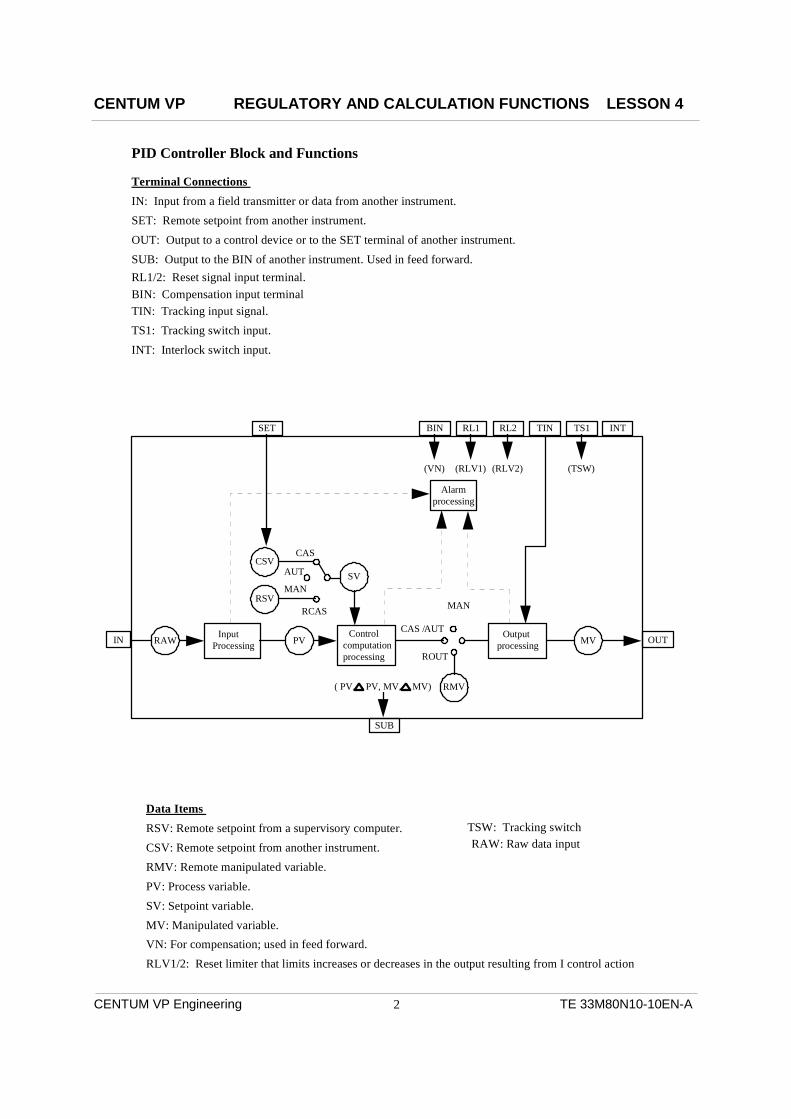
PID Controller Block and Functions
Data Items RSV: Remote setpoint from a supervisory computer.CSV: Remote setpoint from another instrument.RMV: Remote manipulated variable.PV: Process variable.SV: Setpoint variable. MV: Manipulated variable.
Terminal Connections IN: Input from a field transmitter or data from another instrument.SET: Remote setpoint from another instrument.OUT: Output to a control device or to the SET terminal of another instrument.SUB: Output to the BIN of another instrument. Used in feed forward.
VN: For compensation; used in feed forward.RLV1/2: Reset limiter that limits increases or decreases in the output resulting from I control action
IN OUT
SUB
CSV
RSV
SV
RMVPV, PV, MV, MV)
CAS
AUT
MAN
RCAS
(
MAN
CAS /AUT
(VN) (RLV1) (RLV2) (TSW)
Alarmprocessing
MVInputProcessing
Output processing
Controlcomputationprocessing
RAW PV
ROUT
SET TIN TS1 INTBIN RL1 RL2
TSW: Tracking switchRAW: Raw data input
RL1/2: Reset signal input terminal.
TIN: Tracking input signal.TS1: Tracking switch input.INT: Interlock switch input.
BIN: Compensation input terminal
CENTUM VP REGULATORY AND CALCULATION FUNCTIONS LESSON 4
CENTUM VP Engineering TE 33M80N10-10EN-A
3
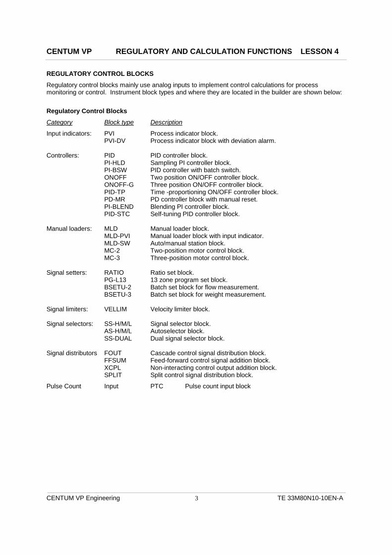
REGULATORY CONTROL BLOCKS
Regulatory control blocks mainly use analog inputs to implement control calculations for process monitoring or control. Instrument block types and where they are located in the builder are shown below:
Regulatory Control Blocks
Category Block type Description
Input indicators: PVI Process indicator block. PVI-DV Process indicator block with deviation alarm. Controllers: PID PID controller block. PI-HLD Sampling PI controller block. PI-BSW PID controller with batch switch. ONOFF Two position ON/OFF controller block. ONOFF-G Three position ON/OFF controller block. PID-TP Time -proportioning ON/OFF controller block. PD-MR PD controller block with manual reset. PI-BLEND Blending PI controller block. PID-STC Self-tuning PID controller block. Manual loaders: MLD Manual loader block. MLD-PVI Manual loader block with input indicator. MLD-SW Auto/manual station block. MC-2 Two-position motor control block. MC-3 Three-position motor control block. Signal setters: RATIO Ratio set block. PG-L13 13 zone program set block. BSETU-2 Batch set block for flow measurement. BSETU-3 Batch set block for weight measurement. Signal limiters: VELLIM Velocity limiter block. Signal selectors: SS-H/M/L Signal selector block. AS-H/M/L Autoselector block. SS-DUAL Dual signal selector block. Signal distributors FOUT Cascade control signal distribution block. FFSUM Feed-forward control signal addition block. XCPL Non-interacting control output addition block. SPLIT Split control signal distribution block.
Pulse Count Input PTC Pulse count input block

CENTUM VP REGULATORY AND CALCULATION FUNCTIONS LESSON 4
CENTUM VP Engineering TE 33M80N10-10EN-A
4
PVBAD
CAL
SUM
PVovershootfunction
CAL
CAL
BAD
Analog input SquareRoot Extraction
PulseInput Conversion
DigitalfilterInput
module
Input signal processing
Alarmprocessing
AUT
(
IN OUT
SUB
CSV
RSV
SV
RMVPV,
PV,
MV, MV)
CAS
MAN
RCAS MAN
CAS /AUT
(VN) (RLV1) (RLV2) (TSW)
MVInput
ProcessingOutput
processingControl
computationprocessing
RAW PVROUT
SET TIN TS1 INTBIN RL1 RL2
CommunicationInput Conversion
No Conversion
Integration

CENTUM VP REGULATORY AND CALCULATION FUNCTIONS LESSON 4
CENTUM VP Engineering TE 33M80N10-10EN-A
5
INPUT SIGNAL PROCESSING
On a regulatory control function block the input signal is brought into the instrument (from the field or from another instrument) and then manipulated to fit the specific requirements of the loop. The common input processing functions are: Input Signal Conversion Linear: No conversion. Square root: 0.5% cutoff. Pulse input: 0-10,000Hz. Digital Filtering Auto filtering or 3 selectable filter types (.5, .75, and .875). Totalizer Time units of: Second, Minute, Hour, or Day (based upon the engineering units), 8 digits maximum. PV Overshoot Function If the input goes bad the PV displays either the last good input or the Hi or Low range limits. Calibration Manually set the PV in case of transmitter failure or calibration.
CENTUM VP REGULATORY AND CALCULATION FUNCTIONS LESSON 4
CENTUM VP Engineering TE 33M80N10-10EN-A
6
Alarmprocessing
AUT
(
IN OUT
SUB
CSV
RSV
SV
RMVPV, PV, MV, MV)
CAS
MAN
RCAS MAN
CAS /AUT
(VN) (RLV1) (RLV2) (TSW)
MVInput
ProcessingOutput
processingControl
computationprocessing
RAW PVROUT
SET TIN TS1 INTBIN RL1 RL2
SV
Output signal processing
AUT/CAS/RCAS/PRD
MH ML
TRK
ROUT
MAN/TRK
MVrb
OUT
SUB
TIN
Preset manipulated output
RMV
Controlcomputation
Outputvelocitylimiter
Outputsignal
conversion
Auxiliaryoutput
TRK
MAN
Outputlimiter
Readback value fromoutput destination
Outputmodule
AUT/CAS/RCAS/ROUT/PRD
MV
+
+
+
-
PV

CENTUM VP REGULATORY AND CALCULATION FUNCTIONS LESSON 4
CENTUM VP Engineering TE 33M80N10-10EN-A
7
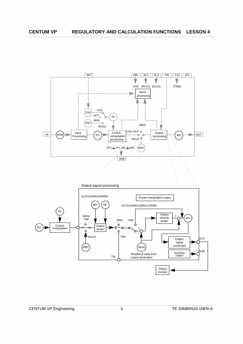
OUTPUT SIGNAL PROCESSING
The previous page shows the signal flow through the output-processing portion of regulatory control function blocks. After the signal has gone through the input processing and the control calculations (PID) then it is ready for the output processing. The control calculation is limited by the output limiter and by the velocity limiter before the signal is displayed as the MV of the instrument on the faceplate. From that point the signal goes through a signal conversion, then to the output module, and then finally to the control element. Functions in the “Output Signal Processing Block” are:
Output Limiter: Limits the function block’s output to the output module; this is displayed as the MH and ML on the tuning panel. Output Velocity Limiter: This function limits the rate of change in the output to avoid output bumps. Output Clamp: Refers to the inability to move the MV above or below the preset output limits. It displays on the instrument faceplate as CLP+ or CLP-. Preset Manipulated Variable: A preset MV (PMV) value can be specified for a function block then be activated by a sequence table based upon predefined set of conditions in the process. The loop will be forced to MAN when this function is used. The output can also be forced to 0% or 100% by a sequence table. Output Tracking: Output tracking function forces the MV of the control block to equal the value of the tracking input signal (TIN) that is coming from an external source or the value of the output’s destination (Cascade connection). Output Signal Conversion: Change the signal from analog to digital for ON/OFF control (depends upon the type of PID function block created). Analog Output: The MV signal to the analog output module generates the 4-20 mA (or 1-5 Vdc) to the control device in the field. The output has a function that makes the signal to the control device go to 106.25% on a full open and -17.19% on a full close. The output of the loop can be reversed (20-4 mA or 5-1 Vdc).
-17.19% 0.00% 100.00% 106.25%
1.25 mA 4.00 mA 20.00 mA 21.00 mA
CENTUM VP REGULATORY AND CALCULATION FUNCTIONS LESSON 4
CENTUM VP Engineering TE 33M80N10-10EN-A
8
IN OUT
BSET
PV
SW
MVInputProcessing
Output processing
MAN
AUT
SUM
Batchset pattern
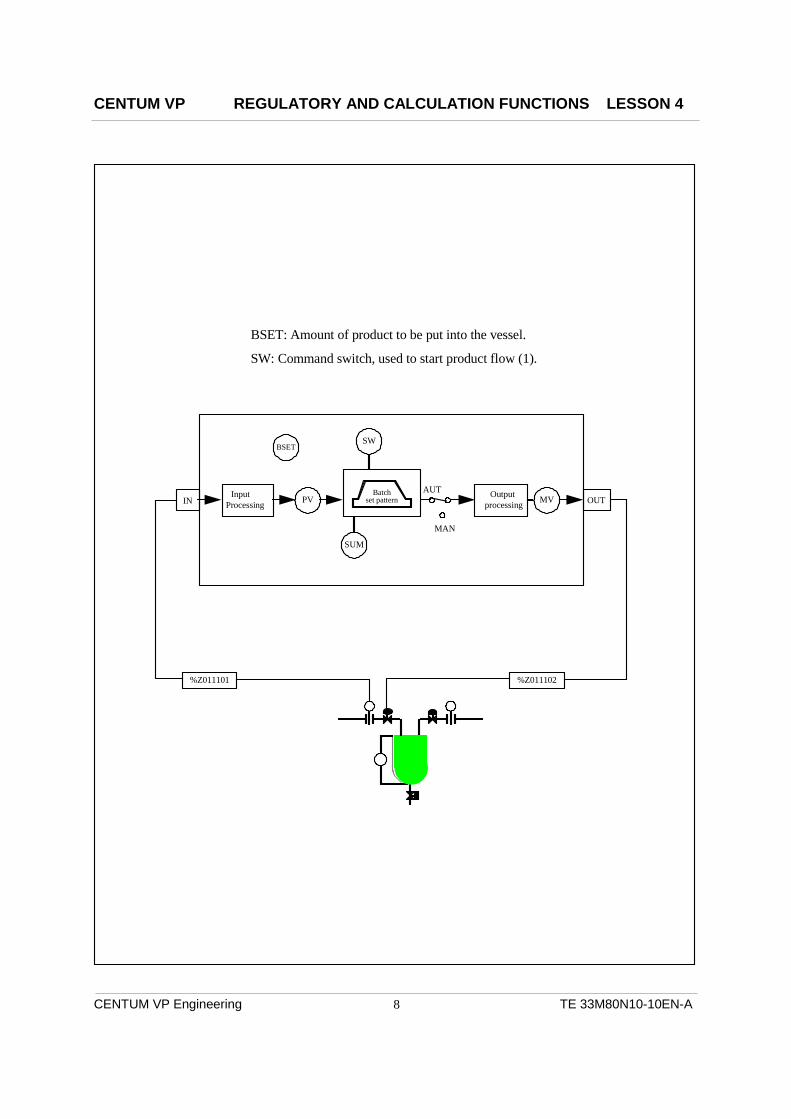
BSET: Amount of product to be put into the vessel.
SW: Command switch, used to start product flow (1).
%Z011101 %Z011102

CENTUM VP REGULATORY AND CALCULATION FUNCTIONS LESSON 4
CENTUM VP Engineering TE 33M80N10-10EN-A
9
BATCH SET BLOCK (BSETU-2)
Another example of a regulatory control type instrument (Signal Setters) is the BSETU-2. This instrument is used in batch control applications such as filling reactors; the fill rate and the shutoff rate can be specified.
This instrument’s flow rate is setup by defining its scaling (shown as the “Scale high”).
• The bar on the faceplate shows the amount of product put into the vessel.
Some of the definable items on the Tuning Panel are:
• The “BSET” register shows amount of product to be put into the vessel. This also defines the scaling on the faceplate.
• The time to open (TU) or close (TD) the control valve in seconds
• The point when the closing of the control valve should start is the “PLST” register. This number is the amount subtracted from the BSET which determines the trigger point.
BSET = 2500
PLST = 200
Closing starts at “2300” (BSET-PLST) at the “TD” rate.
To start a BSETU-2
• The mode must be AUT.
• Command switch SW=1.

CENTUM VP REGULATORY AND CALCULATION FUNCTIONS LESSON 4
CENTUM VP Engineering TE 33M80N10-10EN-A
10
SET BIN RL1 RL2 TIN TS1 INT
IN OUT
SUB
CSV RSV
PV
SV
MV RMV
Input Processing Control
Calculations
(VN) (RLV1) (RLV2) (TSW)
Output Processing
PV, PV, MV, MV)
CAS AUT MAN
RCAS
(
MAN CAS / AUT
Data item Connection Terminal Processing function
Data item
Connection Terminal
PID function block
IN Data Referencing
OUT
SET
IN
OUT IN
MV
OUT IN
VN SUB
%Z011107 %Z011109 %Z011108
Connection Terminal Connection Terminal
Process Connection
Process Connection
Data Setting
J01 P
S10
S11 S12 SV
J02 BDSET-1 SETUP
PID TIC100
PVI TI100
PID TIC200
PID FIC100
SW-33 OUT-SW
MV
TI200.PV
J03
Link Blocks
I
CENTUM VP REGULATORY AND CALCULATION FUNCTIONS LESSON 4
CENTUM VP Engineering TE 33M80N10-10EN-A
11
SIGNAL WIRING
Wiring on a Control Drawing is based upon the data type and the instrument type involved. There are several different wiring types available for connecting instruments and the process. These different types of wiring are: Process Connection: Wiring to or from an I/O connection box. This tells which I/O point will be used for the specific tag. Terminal Connection: Connection between two connection terminals. As an example; from the “OUT” of a PID instrument to “SET” of a secondary instrument in a cascade configuration. Check the FCS configuration manual for all of the allowable terminal connections. Data Referencing: A data item can be taken from one instrument and used in another function block. To do this, the required data item will be named on the output of one block and connected to the IN (as an example) of another block. Data Setting: CS 3000 has software instruments that can be used to change certain data items or gather data from within another function block. As an example of what can be changed: P, I, D, HH, HI, LO, LL, MH, and ML.
• The specific tag number and data type to be changed is defined on the detail panel.
• The actual data to load is defined on the “Tuning Panel”.
Shown below is a reference chart to showing examples of some allowable connections. This does not cover all possible combinations; please refer to the IM’s for specific detail.
Terminal Connectable Items
IN Input modules (%Z), Data types (PV, SV, MV, etc), Switches (SW-33, SW-91).
OUT Output modules (%Z), SET terminal (cascade), Switches (SW-33, SW-91).
SET OUT terminal of “Primary” instrument (cascade), Switches (SW-33, SW-91).
SUB Connect to the VN register (feed forward).

CENTUM VP REGULATORY AND CALCULATION FUNCTIONS LESSON 4
CENTUM VP Engineering TE 33M80N10-10EN-A
12
Link Block
Wiring
Link Block
Wiring

CENTUM VP REGULATORY AND CALCULATION FUNCTIONS LESSON 4
CENTUM VP Engineering TE 33M80N10-10EN-A
13
DEFINING REGULATORY FUNCTION BLOCKS
Select “Function Block” under an FCS and builder “drawings” will appear under “Opened Folder”. Double-click on a drawing number to open its builder panel.
• There are 200 drawings available per FCS on CS3000.
Click on the “Function Block” icon to open the “Select Function Block” window. From here the user will select the category and sub-category to find a desired function block type.
Process Data I/O Connections Connections to the I/O modules is completed through the "Link Block" on the control drawing. The address of the module (%Zxxxxxx) or "User Defined Label" is entered into the box.
Inter/Intra FCS Process Data Process data can be brought from one function block to another by using the "AREAIN" and "AREAOUT" link blocks.
The "AREAIN" is used to bring process data from a function block in the same FCS to the "IN" (or "SET" of a cascade loop). The "AREAOUT" is used to bring process data from a function block in a different FCS to the "IN" (or "SET" of a cascade loop).
OUT
SET
IN
OUT
SET
IN
%Z011101 %Z011102 %Z011109
“Input Connection” “Output Connection”
“Output Connection” To secondary instrument “SET” terminal. FIC100.SET
“Set Value Input Connection” Tag where the “Set Point” gets its data. TIC100.OUT
“Input Connection”
TIC100
PID
FIC100
PID
EFFECTIVE CONNECTIONS
CASCADE

CENTUM VP REGULATORY AND CALCULATION FUNCTIONS LESSON 4
CENTUM VP Engineering TE 33M80N10-10EN-A
14
" Display/Hide Detailed Setting Item"
• Right Mouse Button • “Properties”

CENTUM VP REGULATORY AND CALCULATION FUNCTIONS LESSON 4
CENTUM VP Engineering TE 33M80N10-10EN-A
15
DETAIL SPECIFICATION PANEL
Selecting the “Edit Function Block Detail” icon opens this panel.
• Selecting the right-hand mouse button displays a menu, select “Properties” to see a window where the most commonly changed data items, for the function block, are displayed.
• To see all of the detail items available, select the “Show/Hide Detailed Setting Item” icon.
Items found on the “Show/Hide Detailed Setting Item” panel will vary, depending upon the function block created. The example used here is for a PID type instrument.
The detail specification panel is where the user will define:
• The loop’s input signal range.
• If “Measure Tracking” is to be used.
• Alarms.
• Control algorithm (if it is a control instrument).
• Pre-define detail items (P, I, HH, PH, etc) on the “Fixed Constant”.

CENTUM VP REGULATORY AND CALCULATION FUNCTIONS LESSON 4
CENTUM VP Engineering TE 33M80N10-10EN-A
16
Logic Operation OUT
IN
Q01
General Structure of Arithmetic Calculation Blocks
R User defined
OUT
Q07
IN
Q01
J03
J01
SUB
CPV CPV) (
InpuProcessing Arithmetic/logic
Operation
RV1
RV7
CP
CPV1
CPV3
Output Processing
General purpose Calculation Block
Some Auxiliary Calculation Blocks
S11
S12
S13
S14
S15
S16
S17
S18
S19
S10
1
2
3
4
5
6
7
8
9
0 OF
S
S
Batch data
Batch data 2
Batch data 3
Batch data 4
Batch data 16 J16
J01
J02
J03
J04 Command switch
BDSET-1L SW-91
RV
RV1 Gain RV1 Bias
RInput Processing
CPGain
Bias
Command switch
CPV2 J02
P01 P08

CENTUM VP REGULATORY AND CALCULATION FUNCTIONS LESSON 4
CENTUM VP Engineering TE 33M80N10-10EN-A
17
CALCULATION FUNCTIONS
Calculation function blocks are used to support regulatory control and sequence control functions, and provide general-purpose calculation functions for analog and contact signals. Calculation blocks are divided into six types depending upon the kind of calculations they perform:
1. Arithmetic Calculation Blocks: Each arithmetic calculation has a fixed number of I/O points and fixed calculation algorithm; it performs the basic arithmetic calculations for analog signals. Examples of these are:
ADD MUL DIV AVE
2. Analog Calculation Blocks: Each analog calculation block has a fixed number of I/O points and fixed calculation algorithm: it performs arithmetic calculation for analog signals. Examples of these are: SQRT Square root EXP Exponential block LAG First order lag INTEG Integration block RAMP Ramp block LD Derivative block LDLAG Lead/lag block FUNC-VAR Variable line-segment function block DLAY Dead time block TPCFL Temperature and pressure correction AVE-M Moving average block AVE-C Cumulative average block ASTM1 ASTM (Old JIS) ASTM-2 (New JIS) 3. Calculation Auxiliary 1 Blocks: These blocks have the various functions to assist the control computation. Examples of these are: SW-33 Three pole, 3-position switch. DSW-16 Selector switch for 16 constant (numerical). SW-91 One pole, 9 position switch. DSW-16C Selector switch for 16 constant (character string). DSET Data set block. DSET-PVI Data set block with PVI. 4. Batch Data Blocks: These blocks have functions to assist the setting or gathering of batch data. Examples of these are: BDSET-1L One batch data set block. BDSET-1C One batch data set block (character string). BDSET-2L Two batch data set block. BDSET-2C Two batch data set block (character string). BDA-L Batch data acquisition BDA-C Batch data acquisition (character string). 5. General Purpose Calculation Blocks: Each general-purpose calculation block has a fixed number of I/O points and but allows the user to define the calculation algorithm. Examples of these are: CALCU General Purpose calculation block CALCU-C General Purpose calculation block with string I/O
CENTUM VP REGULATORY AND CALCULATION FUNCTIONS LESSON 4
CENTUM VP Engineering TE 33M80N10-10EN-A
18
CENTUM VP REGULATORY AND CALCULATION FUNCTIONS LESSON 4
CENTUM VP Engineering TE 33M80N10-10EN-A
19
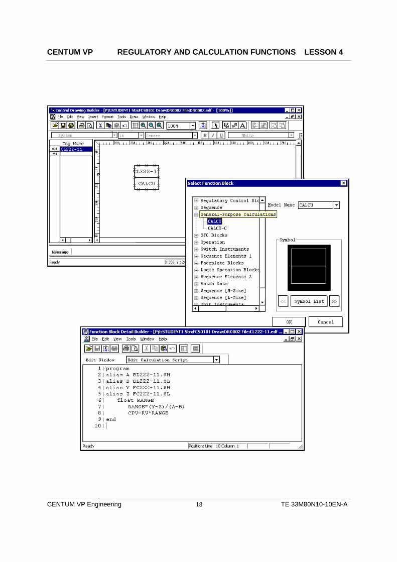
”CALCU” FUNCTION BLOCK
The “CALCU” function block allows the user to create custom calculation to meet specific process needs.
The previous page shows this calculation: 1 program 2 alias A BL222-11.SH 3 alias B BL222-11.SL 4 alias Y FC222-11.SH 5 alias Z FC222-11.SL 6 float RANGE 7 RANGE = (Y-Z) / (A-B) 8 CPV = RV * RANGE 9 end “Alias” allows a tag’s data item to be known by another name (i.e.: BL222-11.SH becomes “A”) “Float” tells RANGE it will be floating-point data. “CPV” is the calculated process variable to be output by this instrument (CL222-11). “RV” is the data coming in through the “IN” terminal block after any input processing.
ON-LINE MANUAL
For more definition of the “CALCU” block, use the “On-line Manual”.
• Create the CALCU Block and, with it selected, click on the “Edit Function Block Detail” icon.
• When the calculation window appears, select “Help”, then “Builder Definition Items”.
• Maximize the on-line manual. On the left-hand side of the on-line manual page, select “Edit Calculation Script” icon just beneath the “General-Purpose Calculations”.
• The menu at the right-hand side changes to display the different calculation data categories.

CENTUM VP REGULATORY AND CALCULATION FUNCTIONS LESSON 4
CENTUM VP Engineering TE 33M80N10-10EN-A
20

CENTUM VP REGULATORY AND CALCULATION FUNCTIONS LESSON 4
CENTUM VP Engineering TE 33M80N10-10EN-A
21
BATCH DATA SET BLOCK (BDSET-1L)
The batch data set block is used primarily in batch processes for adjusting parameters of control loops based upon a product recipe. The BDSET has 16 registers that are accessible from the tuning panel of the instrument. Batch Data Set blocks can be used for changing the values of:
• Setpoint (SV)
• Manipulated variable (MV)
• Alarm trip points (HH, PH, PL, LL, etc.)
• P, I, or D
• Batch settings for BSETU (BSET)
From a sequence table, the BDSET-1L can download either individual registers or all registers at once. An operator can download all registers at the same time.
J01 J02 J03 J04 . . . J16
OUT
SET
IN TIC100 PID
SET
OUT IN RAW-MILK BSETU-2
SV P
BSET
SETUP-1 FCS HIS
DT01 = 150 DT02 = 250 DT03 = 5000 DT04 = 1 . . . DT16
SETUP-1 Tuning Panel
SW
CENTUM VP REGULATORY AND CALCULATION FUNCTIONS LESSON 4
CENTUM VP Engineering TE 33M80N10-10EN-A
22

CENTUM VP REGULATORY AND CALCULATION FUNCTIONS LESSON 4
CENTUM VP Engineering TE 33M80N10-10EN-A
23
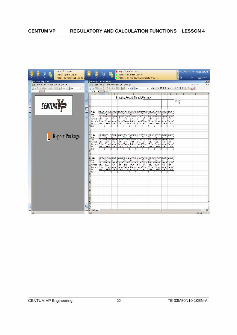
REPORT PACKAGE
A report package option is provided that has pre-defined reports built in that run on Excel spreadsheets. When the report package is opened the user can select from a list of pre-defined reports that fits a specific need from “snap shots”, to shift and hourly reports, and reports that display trend data.
When a report type is selected, data will be entered in to the block fields for:
• Tag name.
• Tag data item.
• Computer name (or operator station) to get data from.
The report is then assigned a unique name and loaded into the report database.
Running a Report
The newly created report can be run from a programmable function key or by the operator station scheduler function, if data is required at a specific time.

CENTUM VP REGULATORY AND CALCULATION FUNCTIONS LESSON 4
CENTUM VP Engineering TE 33M80N10-10EN-A
24
REGULATORY CONTROL EXERCISE 1
This exercise will allow the user to create a cascade PID control and connect the function blocks to the appropriate I/O modules. The loops will then be tested in the “Test Mode”. You may have to refer to previous chapters for more information!
Be aware that the amount of “step by step” direction will gradually decrease as you progress through these exercises.
CREATING FUNCTION BLOCKS FOR EXERCISE 1
1. Bring up “System View” and go to project “STUDENTV”.
2. Click on “Function_Block” under FCS0101 and double click on “DR0001”, at the right hand side of the builder, to open the drawing panel.
3. Select the “Function Block” icon and then click on the ”+” in front of “Regulatory Control Block”. Next open “Controllers” from the expanded list and select “PID” from the next list that appears. Select “OK” and then click on the Control Drawing Builder page to place the PID function block.
4. Define the function block #1 as:
• Tag name: TC222A
5. With the function block selected (green), click the right mouse button and select “Properties”. Change the following items.
• Tag Comment: TEMP CONTROL
• Range: 50.0-300.0
• Engineering unit symbol: DEGF
• Lvl : 3
6. Click again on the panel to create another PID block, define the block as:
• Tag Name: FC222A
• Tag Comment: FLOW CONTROL
• Range: 0-500
• Engineering unit symbol: LB/H
• Totalizer Time Unit: “HOUR”
• Lvl: 3
CENTUM VP REGULATORY AND CALCULATION FUNCTIONS LESSON 4
CENTUM VP Engineering TE 33M80N10-10EN-A
25
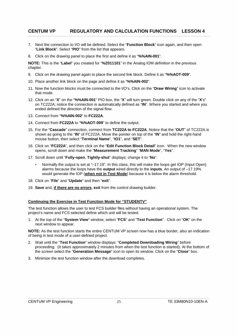
7. Next the connection to I/O will be defined. Select the “Function Block” icon again, and then open “Link Block”. Select “PIO” from the list that appears.
8. Click on the drawing panel to place the first and define it as “%%AIN-001”.
NOTE: This is the “Label” you created for “%Z011101” in the Analog IOM definition in the previous chapter.
9. Click on the drawing panel again to place the second link block. Define it as “%%AOT-009”.
10. Place another link block on the page and define it as “%%AIN-002”.
11. Now the function blocks must be connected to the I/O’s. Click on the “Draw Wiring” icon to activate that mode.
12. Click on an “X” on the “%%AIN-001” PIO box, the “X” will turn green. Double click on any of the “X’s” on TC222A; notice the connection is automatically defined as “IN”. Where you started and where you ended defined the direction of the signal flow.
13. Connect from “%%AIN-002” to FC222A.
14. Connect from FC222A to “%%AOT-009” to define the output.
15. For the “Cascade” connection, connect from TC222A to FC222A. Notice that the “OUT” of TC222A is shown as going to the “IN” of FC222A. Move the pointer on top of the “IN” and hold the right-hand mouse button, then select “Terminal Name”, “IO1”, and “SET”.
16. Click on “FC222A”, and then click on the “Edit Function Block Detail” icon. When the new window opens, scroll down and make the “Measurement Tracking” “MAN Mode”, “Yes”.
17. Scroll down until “Fully-open, Tightly-shut” displays; change it to “No”.
• Normally the output is set at “–17.19”. In this class, this will make the loops get IOP (Input Open) alarms because the loops have the output wired directly to the inputs. An output of –17.19% would generate the IOP (when not in Test Mode) because it is below the alarm threshold.
18. Click on “File” and “Update” and then “exit”.
19. Save and, if there are no errors, exit from the control drawing builder.
Continuing the Exercise in Test Function Mode for “STUDENTV”
The test function allows the user to test FCS builder files without having an operational system. The project’s name and FCS selected define which unit will be tested.
1. At the top of the “System View” window, select “FCS” and “Test Function”. Click on “OK” on the next window to appear.
NOTE: As the test function starts the entire CENTUM VP screen now has a blue border, also an indication of being in test mode of a user-defined project.
2. Wait until the “Test Function” window displays: “Completed Downloading Wiring” before proceeding. (It takes approximately 2 minutes from when the test function is started). At the bottom of the screen select the “Generation Message” icon to open its window. Click on the “Close” box.
3. Minimize the test function window after the download completes.

CENTUM VP REGULATORY AND CALCULATION FUNCTIONS LESSON 4
CENTUM VP Engineering TE 33M80N10-10EN-A
26
Open the “Test Function” window at the bottom of the screen, then select “Tools”, and then “Wiring Editor”.
Now, select “File” and “Open”. When the new window appears, select the new drawing’s number and “Open”.
Use the scroll bar to find “Lag” and enter “10” for both loops. Also make sure that “Bias” is 0.
Click on “File” and “Save”. Make sure your drawing is selected on the next window to open and click on “OK”. NOTE: The “Wiring Editor” is only used for control drawings that are simulating process connections. Using the “Lag” or “Delay”, as an example, you can simulate the process response for you loops.
Displaying the Graphic Blocks
1. Under the STUDENTV Project, expand “HIS0164” and then highlight “Window”. Click on your right-hand mouse button and select “Create New” and “Window” from the menus that appear. The “Create New Window” builder window appears.
2. Select “Control (8 loop)” for the “Window Type” and change the “Window Name” to “TEMP-CTL”. Now, click on “OK”.
3. “TEMP-CTL” now appears in the list of files under “Window”, double click on it to display the graphic builder panel.
4. Click on the faceplate at the left-hand side to select it, now click your right-hand mouse button. When the new menu appears, click on “Properties”.
5. Under Winforms Control, click on Property Page. Define the tag name as “TC222A” and click “OK”.
6. Now, click on the faceplate in position 2 and define its tag name as “FC222A”, and then “OK”.
7. Save and exit from this builder.
8. Minimize the “System View” window, and then click on “NAME” in the system message area. Enter “TEMP-CTL”.
9. Click on TC222A, an arrow displays on its faceplate to show it is selected and open its “Tuning Window”.
10. When the tuning panel appears, scroll over to display “P” and “I”. Select and change P=150 and I=5. Now close this window. Make the same change to FC222A and then close its tuning panel.
11. On the window “TEMP-CTL”, put FC222A into “CAS”, and TC222A into “AUT”. Click on the box beneath TC222A and set the “SV” to 125.
12. Change TC222A’s setpoint by clicking on the SV arrow, and use the ramping arrows in the box that appears.
13. Put FC222A to “MAN” and ramp its MV up and down. What happened? ___Why?
14. Click on the “Clear All” icon in the “System Message Area”, and close the “Tool Box”.
CENTUM VP REGULATORY AND CALCULATION FUNCTIONS LESSON 4
CENTUM VP Engineering TE 33M80N10-10EN-A
27
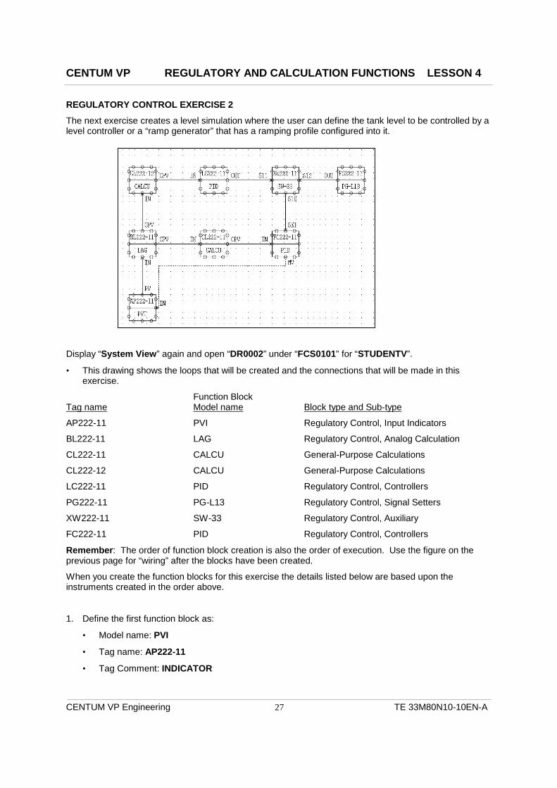
REGULATORY CONTROL EXERCISE 2
The next exercise creates a level simulation where the user can define the tank level to be controlled by a level controller or a “ramp generator” that has a ramping profile configured into it.
Display “System View” again and open “DR0002” under “FCS0101” for “STUDENTV”.
• This drawing shows the loops that will be created and the connections that will be made in this exercise.
Function Block Tag name Model name Block type and Sub-type
AP222-11 PVI Regulatory Control, Input Indicators
BL222-11 LAG Regulatory Control, Analog Calculation
CL222-11 CALCU General-Purpose Calculations
CL222-12 CALCU General-Purpose Calculations
LC222-11 PID Regulatory Control, Controllers
PG222-11 PG-L13 Regulatory Control, Signal Setters
XW222-11 SW-33 Regulatory Control, Auxiliary
FC222-11 PID Regulatory Control, Controllers
Remember: The order of function block creation is also the order of execution. Use the figure on the previous page for “wiring” after the blocks have been created.
When you create the function blocks for this exercise the details listed below are based upon the instruments created in the order above.
1. Define the first function block as:
• Model name: PVI
• Tag name: AP222-11
• Tag Comment: INDICATOR

CENTUM VP REGULATORY AND CALCULATION FUNCTIONS LESSON 4
CENTUM VP Engineering TE 33M80N10-10EN-A
28
2. Define the next function block as:
• Model name: LAG
• Tag Name: BL222-11
• Tag Comment: LAG
3. Define the function block #3 as:
• Model name: CALCU
• Tag name: CL222-11
• Tag Comment: SCALE RANGE CONVERT 1
• High Range: 50.0
• Engineering unit symbol: M3/H
CREATING THE CALCULATION
Using the On-Line Manuals for CALCU Function Block information
4. With the calculation block selected, click on the “Edit Function Block Detail” icon to open up the calculation builder. Now, do the following:
• Click on “Help”, and then “Builder Definition Item”. When “Adobe” opens the on-line manual, maximize the screen by clicking on the single box in the upper right-hand corner of this new window.
• Open up Function Block Detail Builder (on the left under Builder Items).
• In the left-hand column click on “Edit Calculation Script” book icon and then select “Basics of Arithmetic Calculation Description”, in the right-hand window to take you to the beginning of its chapter.
• Using the “Find” icon, enter “Alias Definition”. Double click on the 1st one found at the bottom of the page.
• What does an “Alias” do?
• Close the Adobe reader.
5. Go to the “Edit Function Block Detail” icon and enter the following calculation in CL222-11:
program alias A BL222-11.SH alias B BL222-11.SL alias Y FC222-11.SH alias Z FC222-11.SL float RANGE RANGE=(Y-Z)/(A-B) CPV=RV*RANGE end
• “Update” and exit from the calculation builder.
6. Define the next function block as:
CENTUM VP REGULATORY AND CALCULATION FUNCTIONS LESSON 4
CENTUM VP Engineering TE 33M80N10-10EN-A
29
• Model name: CALCU
• Tag name: CL222-12
• Tag Comment: SCALE RANGE CONVERT 2
7. Now you will create the calculation to run inside of the CALCU block.
• Select “Edit Function Block Detail” and enter the following calculation:
program alias A BL222-11.SH alias B BL222-11.SL alias Y LC222-11.SH alias Z LC222-11.SL float RANGE RANGE=(Y-Z)/(A-B) CPV=RV*RANGE end
• “Update” and exit from the calculation.
8. Define the next function block as:
• Model name: PID
• Tag name: LC222-11
• Tag Comment: LEVEL CONTROL
• Lvl: 3
• Select “Edit Function Block Detail ” icon, then click on the “Show/Hide Detailed Setting Item” icon enter the following:
• Under “Basic”, find “Measurement Tracking” set “MAN Mode”: Yes
• Under “Output”, find “MV Display style”: Self
• Under “Output”, “MV Display style” find “MV Range High Limit”: 50.0
• Under “Output”, “MV Display style” find “MV Engineering Unit Symbol”: M3/H
NOTE: This defines the output of this function block (MV) to be scaled the same as the function block it will control.
• “Update” and exit from the detail window.

CENTUM VP REGULATORY AND CALCULATION FUNCTIONS LESSON 4
CENTUM VP Engineering TE 33M80N10-10EN-A
30
9. Define the function block #6 as:
• Model name: PG-L13
• Tag Name: PG222-11
• Tag Comment: PROGRAM CONTROL
• Lvl: 3
• Select “Edit Function Block Detail” icon, then click on the “Show/Hide Detailed Setting Item” icon enter the following:
• Under “Basic”, find “Total Elapsed Time”: 500
• Under “Control Calculation”, find “When Program Exit”: Quick Return.
• Refer to the “PG-L13” in the “On-line Manual” to answer this next question:
Using the On-Line Manuals for PG-L13 Function Block Details
10. Click on “Help”, and then “Builder Definition Item”. When “Adobe” opens the on-line manual, maximize the screen.
11. Click on “Edit” in the upper left-hand corner of the Adobe page and then on “Find”, enter “D1.19” and enter.
12. Double click on the D1.19 section under the search result. This will take you to the top of the section on PG-L13.
13. Using the “Find” icon, enter “Quick Return”. Double click on “Quick Return Type” at the bottom.
• What does “Quick Return” do?
• You will use this function again in a later exercise!
14. Close the Adobe reader.
15. Back on the PG-L13’s detail definition window define:
• Under “Output”, find “MV Display style”: Self
• Under “Output”, “MV Display style” find “Range High Limit”: 50.0
• Under “Output”, “MV Display style” find “Engineering Unit Symbol”: M3/H
• “Update” and exit from the detail window.
16. Define the function block #7 as:
• Model name: SW-33
• Tag name: XW222-11
• Tag Comment: SWITCH
• Lvl: 3

CENTUM VP REGULATORY AND CALCULATION FUNCTIONS LESSON 4
CENTUM VP Engineering TE 33M80N10-10EN-A
31
17. Define the function block #8 as:
• Model name: PID
• Tag name: FC222-11
• Tag Comment: FLOW CONTROL
• High Range: 50.0
• Engineering unit symbol: M3/H
• Totalizer Time Unit: HOUR
• Lvl: 3
• Select “Edit Function Block Detail” icon.
• Under “Basic”, find “Totalizer Low-Input Cut Value”: .5%
• “Measure Tracking” for “MAN Mode”: Yes
• “Update” and exit from the detail window.
Now the function blocks must be wired together, using the On-Line Manuals let’s look for more details.
• On the control drawing, click on “Help”, and then “Builder Definition Item”. When “Adobe” opens the on-line manual, maximize the screen. Under Control Drawing scroll down and click on “Wiring”. The on-line manual now displays information on wiring; use the scroll arrow to view this information.
• Close the Adobe reader.
18. Use the figure below as the guide for wiring the function blocks together.
• NOTE: When you are connecting the XW222-11 to FC222-11, the “S10” terminal name does not show up on the right mouse button menu. You will have to type in “S10”.
19. Now, go to “File” on “DR0002” and select “Save”. If there are no errors, exit this drawing.
20. Close the window.
CENTUM VP REGULATORY AND CALCULATION FUNCTIONS LESSON 4
CENTUM VP Engineering TE 33M80N10-10EN-A
32
CREATING OPERATION DISPLAYS
Creating a Control Window
1. Click on “Window” under “HIS0164”. Now, on “System View” window click on “File”, followed by “Create New” and “Window” from the menus that appear. The “Create New Window” builder window appears.
2. Select “Control (8 loop)” for the “Window Type” and change the “Window Name” to “TANK5-CG”. Now, click on “OK”.
3. “TANK5-CG” now appears in the list of files under “Window”, double click on “TANK5-CG” to display its builder panel.
4. Click on the faceplate at the left-hand side to select it, now click your right-hand mouse button. When the new menu appears, click on “Properties”.
5. Under “Winforms Control” in the “Property Page”, the “Instrument Diagram” window appears, define the tag name as “XW222-11” and “Apply”.
6. Now, click on the faceplate in position 2 and define its tag name as “LC222-11”, then “Apply”.
• Define position #3 as “FC222-11”.
• Define position #4 as “PG222-11”.
• Define position #5 as “AP222-11”.
• Define position #6 as “BL222-11”.
• Define position #7 as “CL222-11”.
• Define position #8 as “CL222-12”.
7. Save and Exit from this builder.
Creating an Overview Window
1. Highlight “Window” under HIS0164, right click and choose “Create New” and “Window”.
2. When “Create New Window” appears, change:
• “Window Type” to “Overview”
• “Window Name” to “TANK5-OV”
• “Window Comment” to “TANK 5 CONTROLS”
• Now click on “OK”
3. When the “TANK5-OV” window appears open the graphic builder panel.
4. Select the box in the upper left-hand corner, then click the right-hand button and select “Properties”
5. Click on the “Overview” tab. Make the “Type” as “Comment”, and change the “Comment” box to say “TANK 5 CONTROLS”. “First Line” = “Comment”.
• This defines what will appear in this box when the builder is loaded.
6. Under the Function Tab, change “Function Type” to “Call Window”, make “Window Name” = “Graphic”. Change “Parameter” to be “TANK5-OV”, and close.
• The window name defines the panel type to display when the operator selects this box, and the parameter defines which window (if necessary).

CENTUM VP REGULATORY AND CALCULATION FUNCTIONS LESSON 4
CENTUM VP Engineering TE 33M80N10-10EN-A
33
7. Select the second box down on the left-hand side under “Function Tab”, make the “Function Type” a “Call Window”, make the “Window Name” be “Graphic”, and “Parameter” to be “TANK5-CG”. Click on “Overview” on this builder window and change the “Type” to “View Name”. Change “View Name” to “TANK5-CG” and “First Line Display Type” to “View Name”. Check box on “Use HIS Display Font”. Now close window.
8. Select the third box down on the left-hand side under over view, change the “Type” to “Tag Name”, and “Tag Name” to “FC222-11”. Select “Function” and “Function Type” = Call Window, “Window Name” to “Tuning”, and “Parameter” to “FC222-11”. Click on close.
9. Now, define the 4th and 5th boxes to display, and go to, the tuning panels for “LC222-11”, and “PG222-11”. “Save” and Exit from the overview’s graphic builder.
NOTE: WARNINGS WILL APPEAR FOR THE UNDEFINED BOXES.
10. On “HIS0164” open the “CONFIGURATION” folder.
11. Select “TR0001”, and define the “properties” as “Continuous and Rotary Type” and “1 Second” sampling.
12. Now, display “TR0001”, “Group01” and define the “Acquisition Data” for pens:
• #1: “PG222-11.SV”,
• #2: “PG222-11.MV”,
• #3: “FC222-11.PV”,
• #5 “FC222-11.SUM”, with the limits of 0 to 30000, and defined as “Totalizer Value”.
13. "Save" and exit from this trend.
14. Define “TR0002” sampling period for “Continuous and Rotary” and 10 seconds. Also define the “Acquisition Data” using the tags and data items in the previous step. This trend group would be called up with the name of "TG0201".
15. "Save" and Exit from this trend.
Trend Point Closing
1. Assign these new tags to TR0003, Group 1 on “HIS0164”. In chapter 2 we defined the trend block to sample all assigned data at a 1-minute rate.
2. Define the actual closing process, select “View” at the top of the window followed by “Closing definition” from the menu that appears. New boxes will appear to the right hand side of the screen. Use the scroll bar to bring these boxes into the window.
3. Click on “Monthly” for all of the pens being used (“Hourly” and “Daily” are selected by default), and then "Save" and Exit. This will save all of the settings defined in the previous steps.
NOTE: Remember we previously set up the “Closing Process” for “HIS0164” in chapter 2, page 20.
CENTUM VP REGULATORY AND CALCULATION FUNCTIONS LESSON 4
CENTUM VP Engineering TE 33M80N10-10EN-A
34
Manipulating the Function Blocks
1. Click on “NAME” in the “System Message Area”, and enter “TANK5-OV”. When the window appears try selecting the boxes and see where you go.
2. Display “TANK5-CG”, click on the box beneath XW222-11 to display its data entry window. Enter “1” to connect LC222-11’s OUT to FC222-11’s SET.
3. Select FC222-11 and change its mode to “AUT”. Select the box beneath its faceplate and change the SV data to “30.0”.
4. Click on BL222-11, and then select “Tuning” from the “Window Call Menu”.
5. Click on “I” (first order lag time) and enter “10.0” in the data entry window, then close the tuning panel and return to “TANK5-CG”.
6. Click on FC222-11, then, display its ”Tuning Window”.
• Change the mode to “CAS”.
• Click on “Operation Mark” icon and assign one of the operation marks.
7. Close “FC222-11” tuning window.
8. Display PG222-11’s “Tuning Window” and change the following data items:
• X02=30, X03=60, X04=90, X05=120, X06=150, X07=180, X08=210, X09=240
• Y01=5, Y02=15, Y03=15, Y04=35, Y05=35, Y06=25, Y07=25, Y08=10
Reminder: The “X” registers define time for “ZONES”. A zone is the time the output goes from the Y register setting at the beginning of the zone to the Y register setting at the end of the zone.
• EXAMPLE: Zone #1 starts at X01 (time 0) and ends at X02. The output will ramp from 5 (Y01) to 15 (Y02) during that period.
9. Change PG222-11’s mode to “CAS” then close the tuning panel and return to “TANK5-CG”.
• NOTE: The PG-L13 uses the mode of “CAS” to continually run through its profile. When it is put into the mode of “AUT” then it will run 1 time and then go to “MAN”.
10. Change XW222-11 switch position to “2” and watch the operation of FC222-11.
11. Change PG222-11’s mode to “MAN”, and then display its Tuning panel. What happened to the output?
12. Change PG222-11’s mode back to “CAS” then display “TG0101” and watch the trend data change.
Saving the Tuning Parameters under “Test Function”
The tuning parameters, for a tag, are all of the changeable items on a tuning window at an engineering level. When a project’s FCS is downloaded the last saved tuning parameters are the ones that are used.
1. Make sure all “Control Drawings” are closed.
2. On the “System View” window “Tools” and “Tuning Parameter Saving”.
3. When the “Tuning parameter save continuously” window, select the “Tuning Parameter Save” button.
4. Click “OK” on the next window that appears.
5. Close the both tuning parameter saving windows after the save has completed.

CENTUM VP REGULATORY AND CALCULATION FUNCTIONS LESSON 4
CENTUM VP Engineering TE 33M80N10-10EN-A
35
REPORT PACKAGE
Opening the “Report Package” and creating a “Snap shot” report.
1. On the left- side menu, click on the “Tool Button Tool Box” and under the “Call View” tab select “Logging Report Package”. Excel will open then select “Enable Macros” and the Report opens.
2. Select “Report Tab” from the top menu, under “File”, chose “Open report”. A menu now appears listing the predefined report templates. Now, open the template for “01 SnapshotReport”.
Modifying the report.
1. When the report opens, click on the cell displaying “@TAG001”. Now, under “Menu Commands”, under “Report”, choose “Data Assignment” on the next menu and a new window will open.
2. To set the first report cell up, enter “PG222-11” in the “Tag” box. Next put “MV” in the “Item” box.
3. At the top of the assignment window is a scroll bar with 1/36 displayed at its right-hand side. Click on the right-hand arrow to display cell 2/36.
4. Assign the PV for FC222-11 and LC222-11 to the next two cells. Remember to “Read Datainf” as you assign each cell.
5. Select “OK” when you have finished capturing these settings.
6. To name this report, select “File” and “Save As”. Enter a name for your report (make the name all one word!) in the window that opens.
7. After the report has been saved, click on “File” again and the “Close Report”. This will take you back to the main report page.
Loading the Report
1. To make this new report available, click on “File” and “Load” on the “Report Package” page. When the new window appears, scroll down and click on your report’s name.
2. To make this an active report, click on the “>>” icon to place the report’s name into the “Master” list and then “Exit”.
• Reminder: If you modify a report, you MUST reload the report into the master list to over-write the old report.
3. Minimize the report display; the report is now ready to be run.
CENTUM VP REGULATORY AND CALCULATION FUNCTIONS LESSON 4
CENTUM VP Engineering TE 33M80N10-10EN-A
36
Assigning the Report to the “Preset Menu”
Reports can also be assigned to the programmable Function Keys, Preset Menu or Scheduler. The format is the same for all.
1. Bring up the “System Status Overview” window and click on “HIS Setup” icon. Select the “Preset Menu” tab.
2. Select an un-used line;
• Function Type: “Execute the Program by File Name”
• Program Name: BKHRPT
• Parameter: –nREPORTNAME –f
• -n is followed immediately (no space) by the report’s name.
• Put in a “space” and then -f to dump the report to a file (a “-p” would put the report to a printer).
3. Select “Set” and then “OK”.
4. Open the “Preset Menu” icon and select the report you just assigned to run it.
Displaying the Report
Since we defined the report to be written to a file the following steps show how to display the report.
1. Select the report builder icon at the bottom of the display to open it up (this was previously minimized).
2. When the window opens, select “Report” in its upper left-hand corner and then “History”. Select your report name from the new window and click on “Open”.
• NOTE: The report opens displaying the data captured when the function key was selected. Notice that the unused cells reported errors for their data, since the report could not find the default tag names.
3. To close this report and return to the main report panel, select “File” and “Back to CS3000” and then close the report builder.


