Centrimaster GT1 Technical Catalogue 2002 11 ENG
62
Centrimaster GT-1 Direct driven, single inlet centrifugal fans Technical Data
-
Upload
carlos-pinto -
Category
Documents
-
view
108 -
download
4
Transcript of Centrimaster GT1 Technical Catalogue 2002 11 ENG
Centrimaster GT-1Direct driven, single inlet centrifugal fans
Technical Data

Fläkt Woods Oy FIFLO 4469 GB 02.12 3 Specifications are subject to alteration without notice
Centrimaster GT-1 CATALOGUE
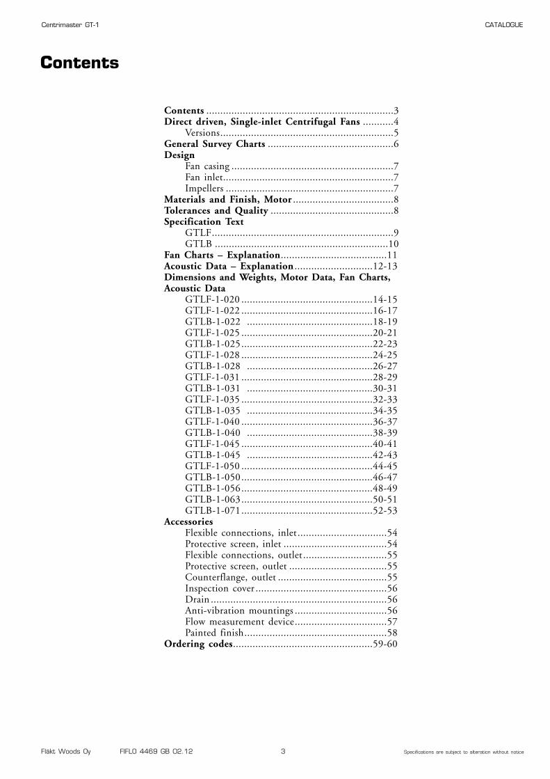
Contents
Contents ...................................................................3Direct driven, Single-inlet Centrifugal Fans ...........4
Versions..............................................................5General Survey Charts .............................................6Design
Fan casing ..........................................................7Fan inlet.............................................................7Impellers ............................................................7
Materials and Finish, Motor ....................................8Tolerances and Quality ............................................8Specification Text
GTLF.................................................................9GTLB ..............................................................10
Fan Charts – Explanation......................................11Acoustic Data – Explanation ............................12-13Dimensions and Weights, Motor Data, Fan Charts,Acoustic Data
GTLF-1-020 ...............................................14-15GTLF-1-022 ...............................................16-17GTLB-1-022 .............................................18-19GTLF-1-025 ...............................................20-21GTLB-1-025...............................................22-23GTLF-1-028 ...............................................24-25GTLB-1-028 .............................................26-27GTLF-1-031 ...............................................28-29GTLB-1-031 .............................................30-31GTLF-1-035 ...............................................32-33GTLB-1-035 .............................................34-35GTLF-1-040 ...............................................36-37GTLB-1-040 .............................................38-39GTLF-1-045 ...............................................40-41GTLB-1-045 .............................................42-43GTLF-1-050 ...............................................44-45GTLB-1-050...............................................46-47GTLB-1-056...............................................48-49GTLB-1-063...............................................50-51GTLB-1-071...............................................52-53
AccessoriesFlexible connections, inlet ................................54Protective screen, inlet .....................................54Flexible connections, outlet ..............................55Protective screen, outlet ...................................55Counterflange, outlet .......................................55Inspection cover ...............................................56Drain ...............................................................56Anti-vibration mountings .................................56Flow measurement device.................................57Painted finish...................................................58
Ordering codes..................................................59-60
Fläkt Woods Oy FIFLO 4469 GB 02.12 4 Specifications are subject to alteration without notice
Centrimaster GT-1 CATALOGUE
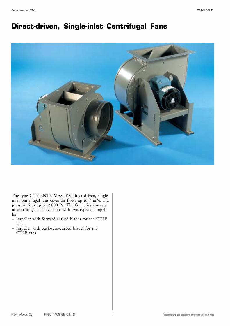
Direct-driven, Single-inlet Centrifugal Fans
The type GT CENTRIMASTER direct driven, single-inlet centrifugal fans cover air flows up to 7 m3/s andpressure rises up to 2.000 Pa. The fan series consistsof centrifugal fans available with two types of impel-ler:– Impeller with forward-curved blades for the GTLF
fans.– Impeller with backward-curved blades for the
GTLB fans.
Fläkt Woods Oy FIFLO 4469 GB 02.12 5 Specifications are subject to alteration without notice
Centrimaster GT-1 CATALOGUE
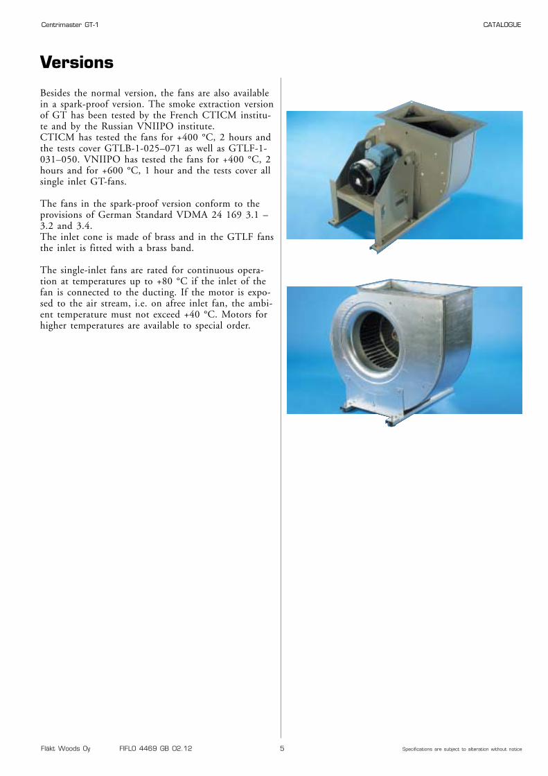
Versions
Besides the normal version, the fans are also availablein a spark-proof version. The smoke extraction versionof GT has been tested by the French CTICM institu-te and by the Russian VNIIPO institute.CTICM has tested the fans for +400 °C, 2 hours andthe tests cover GTLB-1-025–071 as well as GTLF-1-031–050. VNIIPO has tested the fans for +400 °C, 2hours and for +600 °C, 1 hour and the tests cover allsingle inlet GT-fans.
The fans in the spark-proof version conform to theprovisions of German Standard VDMA 24 169 3.1 –3.2 and 3.4.The inlet cone is made of brass and in the GTLF fansthe inlet is fitted with a brass band.
The single-inlet fans are rated for continuous opera-tion at temperatures up to +80 °C if the inlet of thefan is connected to the ducting. If the motor is expo-sed to the air stream, i.e. on afree inlet fan, the ambi-ent temperature must not exceed +40 °C. Motors forhigher temperatures are available to special order.
Fläkt Woods Oy FIFLO 4469 GB 02.12 6 Specifications are subject to alteration without notice
Centrimaster GT-1 CATALOGUE
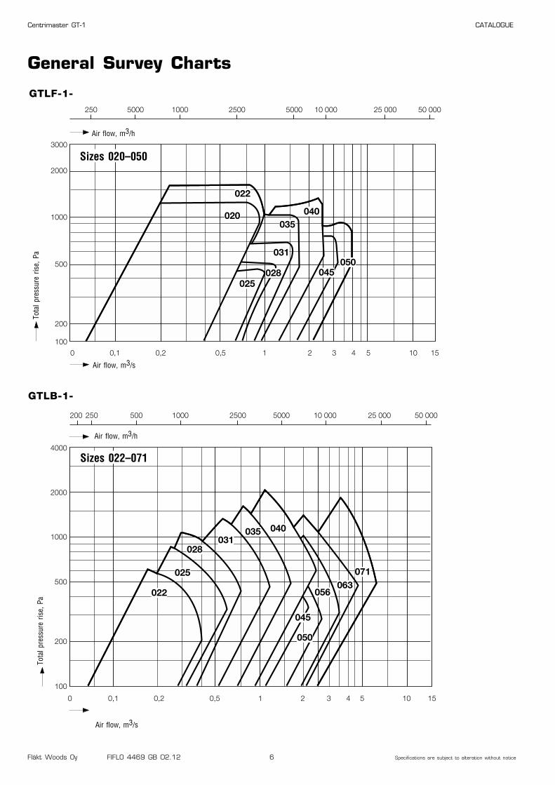
General Survey Charts
GTLF-1-250 5000 1000 2500 5000 10 000 25 000 50 000
0,10 0,2 0,5 1 2 3 4 5 10 15
3000
2000
1000
500
100
200
020
022
028
031
035040
045050
025
Air flow, m3/s
Tota
l pre
ssur
e ris
e, P
a
Sizes 020–050
Air flow, m3/h
0 0,1 0,2 0,5 1 2 3 4 5 10 15
4000
2000
1000
500
200
100
200 250 500 1000 2500 5000 10 000 25 000 50 000
022
025
028031
035 040
045
050
056063
071
Air flow, m3/s
Tota
l pre
ssur
e ris
e, P
a
Sizes 022–071
Air flow, m3/h
GTLB-1-
Fläkt Woods Oy FIFLO 4469 GB 02.12 7 Specifications are subject to alteration without notice
Centrimaster GT-1 CATALOGUE
DesignFan Casing
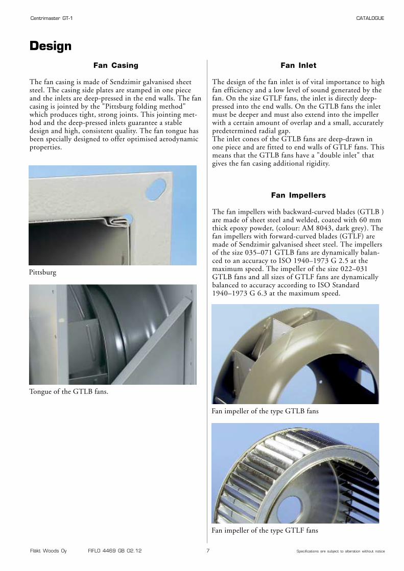
The fan casing is made of Sendzimir galvanised sheetsteel. The casing side plates are stamped in one pieceand the inlets are deep-pressed in the end walls. The fancasing is jointed by the "Pittsburg folding method"which produces tight, strong joints. This jointing met-hod and the deep-pressed inlets guarantee a stabledesign and high, consistent quality. The fan tongue hasbeen specially designed to offer optimised aerodynamicproperties.
Fan Inlet
The design of the fan inlet is of vital importance to highfan efficiency and a low level of sound generated by thefan. On the size GTLF fans, the inlet is directly deep-pressed into the end walls. On the GTLB fans the inletmust be deeper and must also extend into the impellerwith a certain amount of overlap and a small, accuratelypredetermined radial gap.The inlet cones of the GTLB fans are deep-drawn inone piece and are fitted to end walls of GTLF fans. Thismeans that the GTLB fans have a "double inlet" thatgives the fan casing additional rigidity.
Tongue of the GTLB fans.
Pittsburg
Fan Impellers
The fan impellers with backward-curved blades (GTLB )are made of sheet steel and welded, coated with 60 mmthick epoxy powder, (colour: AM 8043, dark grey). Thefan impellers with forward-curved blades (GTLF) aremade of Sendzimir galvanised sheet steel. The impellersof the size 035–071 GTLB fans are dynamically balan-ced to an accuracy to ISO 1940–1973 G 2.5 at themaximum speed. The impeller of the size 022–031GTLB fans and all sizes of GTLF fans are dynamicallybalanced to accuracy according to ISO Standard1940–1973 G 6.3 at the maximum speed.
Fan impeller of the type GTLB fans
Fan impeller of the type GTLF fans
Fläkt Woods Oy FIFLO 4469 GB 02.12 8 Specifications are subject to alteration without notice
Centrimaster GT-1 CATALOGUE
Tolerance Class
DIN 24166 1 2 3
Air flow qv: ±2.5% ±5.0% ±10.0%
Pressure rise, ∆pt: ±2.5% ±5.0% ±10,0%
Shaft power demand*, P: +3.0% +5.0% +16.0%
Efficiency**, h: –2.0% –5.0% –
A-weighted sound power level*, LWA: +3 dB +4 dB +6 dB
* Negative tolerance permissible
** Positive tolerance permissible
Motor
The GT fans are normally supplied with the motormounted. This enables the fan to be trial run prior todispatch and ABB can assume undivided warranty liabi-lity.
Detailed motor data is tabulated in separate tables. Seeunder Motor Data.
Materials and Finish
The GX fans in the standard version meet the provi-sions of Environmental Class M2.
Fan casing: Sendzimir galvanised sheet steel, (275 g/ m2 thick zinc)
Inlet cone: Sendzimir galvanised sheet steel in the normal version. Brass in the spark-proofversion.
Shaft: Centreless-ground steel with anti-corro-sion protection.
Fan impeller: GTLB: Sheet steel, welded, coated with60 mm epoxy powder and baked, colour: AM8043, dark grey.GTLF: Sendzimir galvanised steel.
Materials and Finish, Motor – Tolerances and Quality
Tolerances
The particulars in the charts are given with the toleran-ce specified in the DIN 24 166 Standard, Class 2.
ISO 9001 and ISO 14001 Quality
ABB Fans has received quality management certifi-cation in accordance with ISO 9001. We documentour quality management responsibility at everystage of our business activities from the productdevelopment to production, procurement and mar-keting. We have received environmental management cer-tification in accordance with ISO 14001. We aim tominimise the impact of our business activities andour products on the environment.
Fläkt Woods Oy FIFLO 4469 GB 02.12 9 Specifications are subject to alteration without notice
Centrimaster GT-1 CATALOGUE
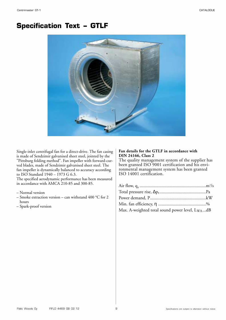
Specification Text – GTLF
Single-inlet centrifugal fan for a direct-drive. The fan casingis made of Sendzimir galvanised sheet steel, jointed by the"Pittsburg folding method". Fan impeller with forward-cur-ved blades, made of Sendzimir galvanised sheet steel. Thefan impeller is dynamically balanced to accuracy accordingto ISO Standard 1940 – 1973 G 6.3.The specified aerodynamic performance has been measuredin accordance with AMCA 210-85 and 300-85.
– Normal version– Smoke extraction version – can withstand 400 °C for 2
hours– Spark-proof version
GXLF
GTLF
Fan details for the GTLF in accordance with DIN 24166, Class 2The quality management system of the supplier hasbeen granted ISO 9001 certification and his envi-ronmental management system has been grantedISO 14001 certification.
Air flow, qv .........................................................m3/sTotal pressure rise, ∆pt........................................PaPower demand, P................................................kWMin. fan efficiency, η .........................................%Max. A-weighted total sound power level, LWA...dB
Fläkt Woods Oy FIFLO 4469 GB 02.12 10 Specifications are subject to alteration without notice
Centrimaster GT-1 CATALOGUE
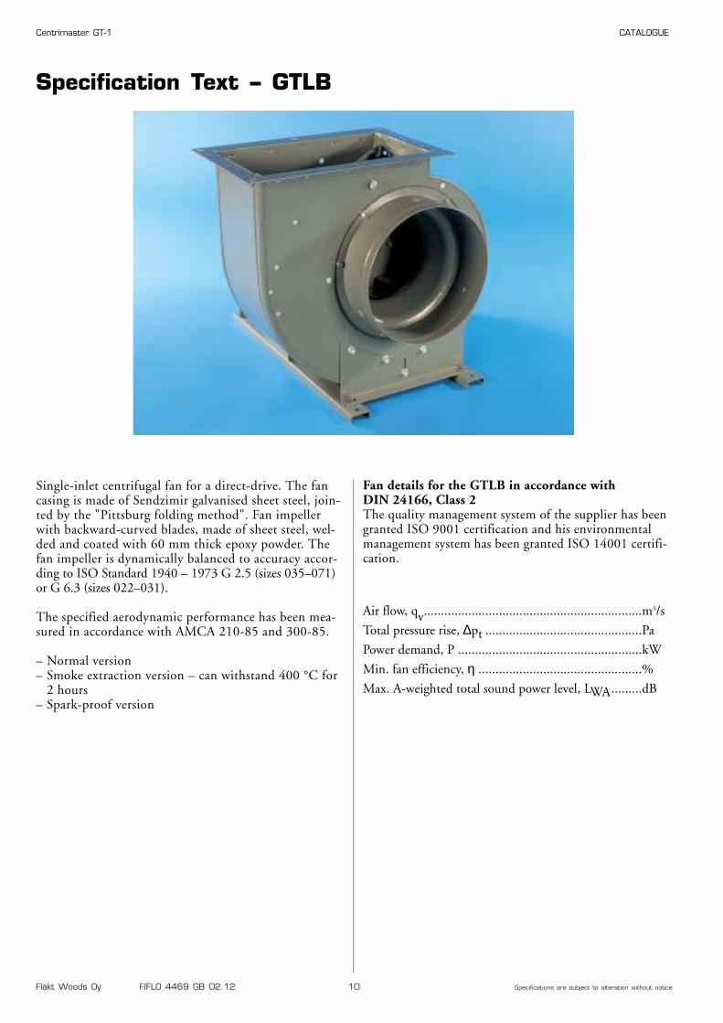
Specification Text – GTLB
Single-inlet centrifugal fan for a direct-drive. The fancasing is made of Sendzimir galvanised sheet steel, join-ted by the "Pittsburg folding method". Fan impellerwith backward-curved blades, made of sheet steel, wel-ded and coated with 60 mm thick epoxy powder. Thefan impeller is dynamically balanced to accuracy accor-ding to ISO Standard 1940 – 1973 G 2.5 (sizes 035–071)or G 6.3 (sizes 022–031).
The specified aerodynamic performance has been mea-sured in accordance with AMCA 210-85 and 300-85.
– Normal version– Smoke extraction version – can withstand 400 °C for
2 hours– Spark-proof version
Fan details for the GTLB in accordance with DIN 24166, Class 2 The quality management system of the supplier has beengranted ISO 9001 certification and his environmentalmanagement system has been granted ISO 14001 certifi-cation.
Air flow, qv................................................................m3/s
Total pressure rise, ∆pt ..............................................Pa
Power demand, P ......................................................kW
Min. fan efficiency, η ................................................%
Max. A-weighted total sound power level, LWA.........dB
GTLB
Fläkt Woods Oy FIFLO 4469 GB 02.12 11 Specifications are subject to alteration without notice
Centrimaster GT-1 CATALOGUE
Fan Charts – Explanation
0 0.4 0.8 1.2 1.6 2 2.4 2.6
50
100
200
500
1000
2000
2500
0.02
0.1
0.4
0.81
2
4
1000 2000 3000 4000 5000 6000 7000 8000 9000
10 20 60 80 100 120 160 200p d Pa
40 100 200 300∆p2+ pd Pa
10 20 40∆p 3 Pa
5 10 20 30 40 50 60∆p 1 Pa
10 20 40∆p 4 Pa
40
60
7075
80 81
8075
η%
4-pole
2-pole
4/6-pole(6)
4/8-pole(8)
qvm3/h
m3/s
J = 0.24 kgm2
∆pt
,Pa
P,k
W
4-pole
2-pole
4/6-pole(6)4/8-pole(8)
,dB 75 80 85 90 95LwA
GTLB-1-0401
2
3
6
9
8
7
5
4
11
10
12
13
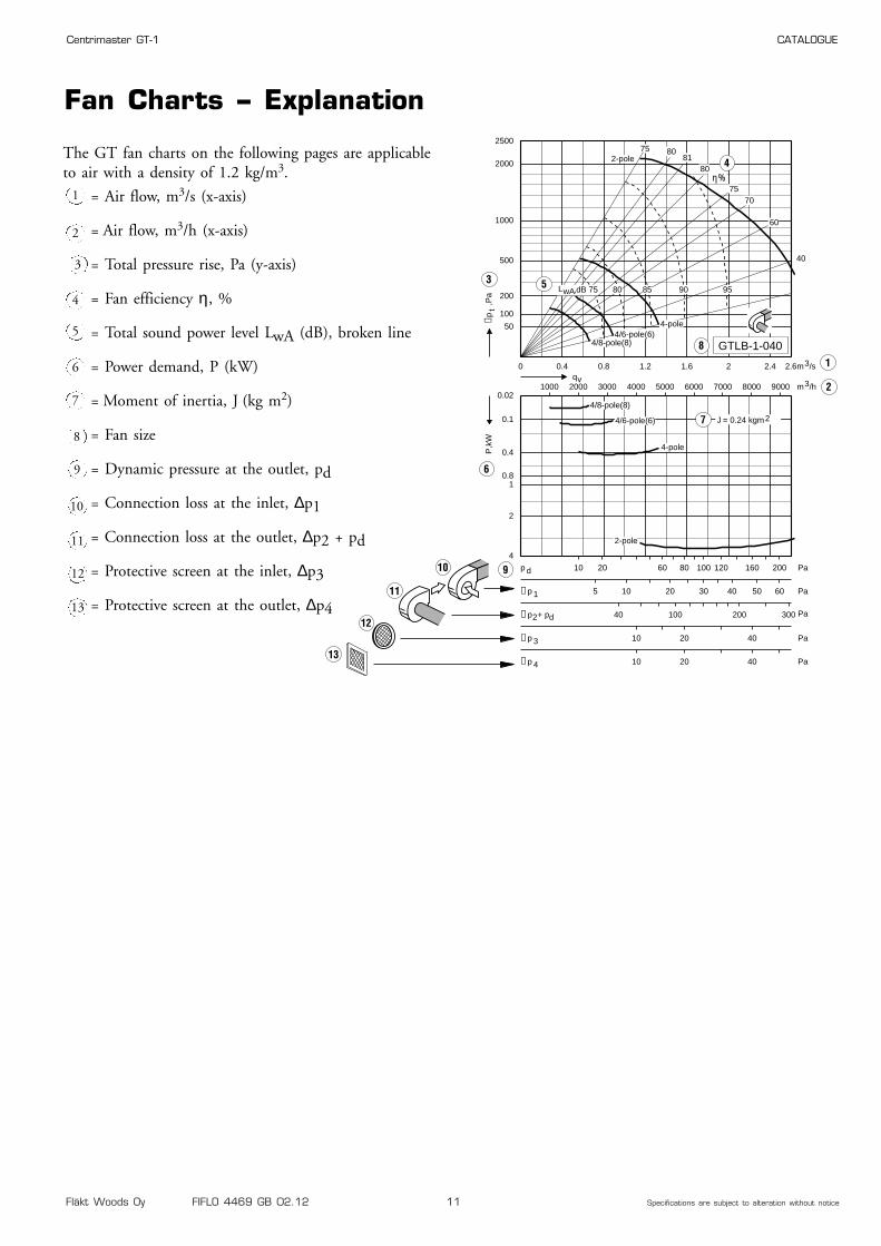
The GT fan charts on the following pages are applicableto air with a density of 1.2 kg/m3.
1 = Air flow, m3/s (x-axis)
= Air flow, m3/h (x-axis)
= Total pressure rise, Pa (y-axis)
= Fan efficiency η, %
= Total sound power level LwA (dB), broken line
= Power demand, P (kW)
= Moment of inertia, J (kg m2)
= Fan size
= Dynamic pressure at the outlet, pd
= Connection loss at the inlet, ∆p1
= Connection loss at the outlet, ∆p2 + pd
= Protective screen at the inlet, ∆p3
= Protective screen at the outlet, ∆p4
2
3
4
5
6
7
8
9
10
11
12
13
Fläkt Woods Oy FIFLO 4469 GB 02.12 12 Specifications are subject to alteration without notice
Centrimaster GT-1 CATALOGUE
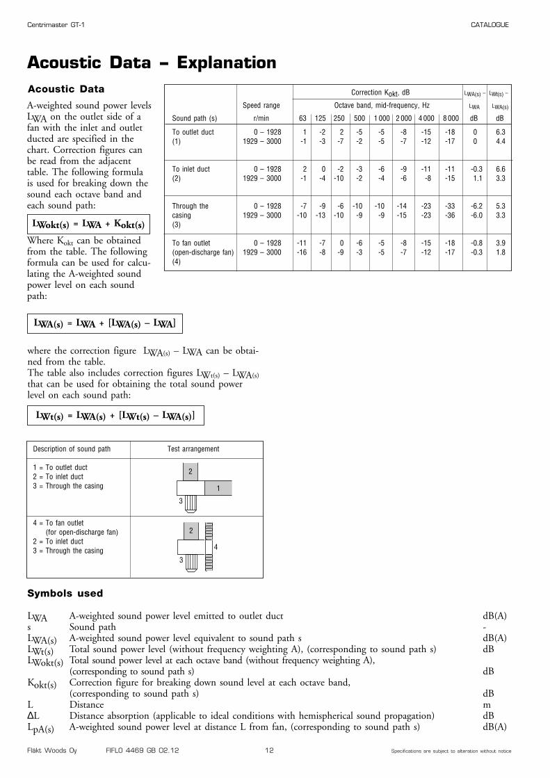
where the correction figure LWA(s) – LWA can be obtai-ned from the table.The table also includes correction figures LWt(s) – LWA(s)that can be used for obtaining the total sound powerlevel on each sound path:
Acoustic Data – Explanation
A-weighted sound power levelsLWA on the outlet side of afan with the inlet and outletducted are specified in thechart. Correction figures canbe read from the adjacenttable. The following formulais used for breaking down thesound each octave band andeach sound path:
Where Kokt can be obtainedfrom the table. The followingformula can be used for calcu-lating the A-weighted soundpower level on each soundpath:
LWokt(s) = LWA + Kokt(s)
Acoustic Data
LWA(s) = LWA + [LWA(s) – LWA]
LWt(s) = LWA(s) + [LWt(s) – LWA(s)]
Description of sound path Test arrangement
1 = To outlet duct2 = To inlet duct3 = Through the casing
4 = To fan outlet(for open-discharge fan)
2 = To inlet duct3 = Through the casing
Symbols used
LWA A-weighted sound power level emitted to outlet duct dB(A)s Sound path -LWA(s) A-weighted sound power level equivalent to sound path s dB(A)LWt(s) Total sound power level (without frequency weighting A), (corresponding to sound path s) dBLWokt(s) Total sound power level at each octave band (without frequency weighting A),
(corresponding to sound path s) dBKokt(s) Correction figure for breaking down sound level at each octave band,
(corresponding to sound path s) dBL Distance m∆L Distance absorption (applicable to ideal conditions with hemispherical sound propagation) dBLpA(s) A-weighted sound power level at distance L from fan, (corresponding to sound path s) dB(A)
2
1
3
2
4
3
Correction Kokt, dB LWA(s) – LWt(s) –
Speed range Octave band, mid-frequency, Hz LWA LWA(s)
Sound path (s) r/min 63 125 250 500 1 000 2 000 4 000 8 000 dB dB
To outlet duct 0 – 1928 1 -2 2 -5 -5 -8 -15 -18 0 6.3(1) 1929 – 3000 -1 -3 -7 -2 -5 -7 -12 -17 0 4.4
To inlet duct 0 – 1928 2 0 -2 -3 -6 -9 -11 -11 -0.3 6.6(2) 1929 – 3000 -1 -4 -10 -2 -4 -6 -8 -15 1.1 3.3
Through the 0 – 1928 -7 -9 -6 -10 -10 -14 -23 -33 -6.2 5.3casing 1929 – 3000 -10 -13 -10 -9 -9 -15 -23 -36 -6.0 3.3(3)
To fan outlet 0 – 1928 -11 -7 0 -6 -5 -8 -15 -18 -0.8 3.9(open-discharge fan) 1929 – 3000 -16 -8 -9 -3 -5 -7 -12 -17 -0.3 1.8(4)
Fläkt Woods Oy FIFLO 4469 GB 02.12 13 Specifications are subject to alteration without notice
Centrimaster GT-1 CATALOGUE
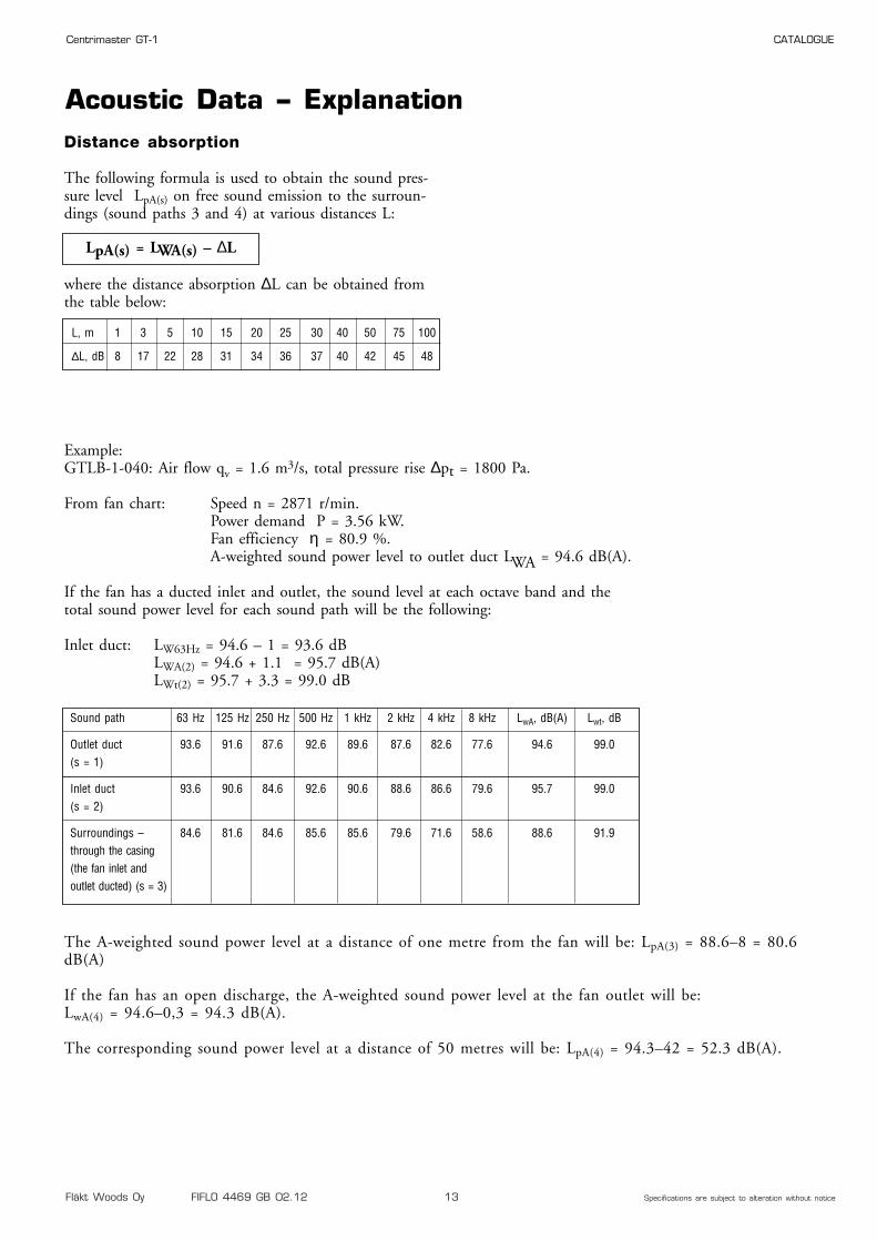
Sound path 63 Hz 125 Hz 250 Hz 500 Hz 1 kHz 2 kHz 4 kHz 8 kHz LwA, dB(A) Lwt, dB
Outlet duct 93.6 91.6 87.6 92.6 89.6 87.6 82.6 77.6 94.6 99.0(s = 1)
Inlet duct 93.6 90.6 84.6 92.6 90.6 88.6 86.6 79.6 95.7 99.0(s = 2)
Surroundings – 84.6 81.6 84.6 85.6 85.6 79.6 71.6 58.6 88.6 91.9through the casing(the fan inlet and outlet ducted) (s = 3)
Acoustic Data – Explanation
The A-weighted sound power level at a distance of one metre from the fan will be: LpA(3) = 88.6–8 = 80.6dB(A)
If the fan has an open discharge, the A-weighted sound power level at the fan outlet will be:LwA(4) = 94.6–0,3 = 94.3 dB(A).
The corresponding sound power level at a distance of 50 metres will be: LpA(4) = 94.3–42 = 52.3 dB(A).
Distance absorption
The following formula is used to obtain the sound pres-sure level LpA(s) on free sound emission to the surroun-dings (sound paths 3 and 4) at various distances L:
where the distance absorption ∆L can be obtained fromthe table below:
LpA(s) = LWA(s) – ∆L
L, m 1 3 5 10 15 20 25 30 40 50 75 100
∆L, dB 8 17 22 28 31 34 36 37 40 42 45 48
Example:GTLB-1-040: Air flow qv = 1.6 m3/s, total pressure rise ∆pt = 1800 Pa.
From fan chart: Speed n = 2871 r/min.Power demand P = 3.56 kW.Fan efficiency η = 80.9 %.A-weighted sound power level to outlet duct LWA = 94.6 dB(A).
If the fan has a ducted inlet and outlet, the sound level at each octave band and thetotal sound power level for each sound path will be the following:
Inlet duct: LW63Hz = 94.6 – 1 = 93.6 dBLWA(2) = 94.6 + 1.1 = 95.7 dB(A)LWt(2) = 95.7 + 3.3 = 99.0 dB
Fläkt Woods Oy FIFLO 4469 GB 02.12 14 Specifications are subject to alteration without notice
Centrimaster GT-1 CATALOGUE
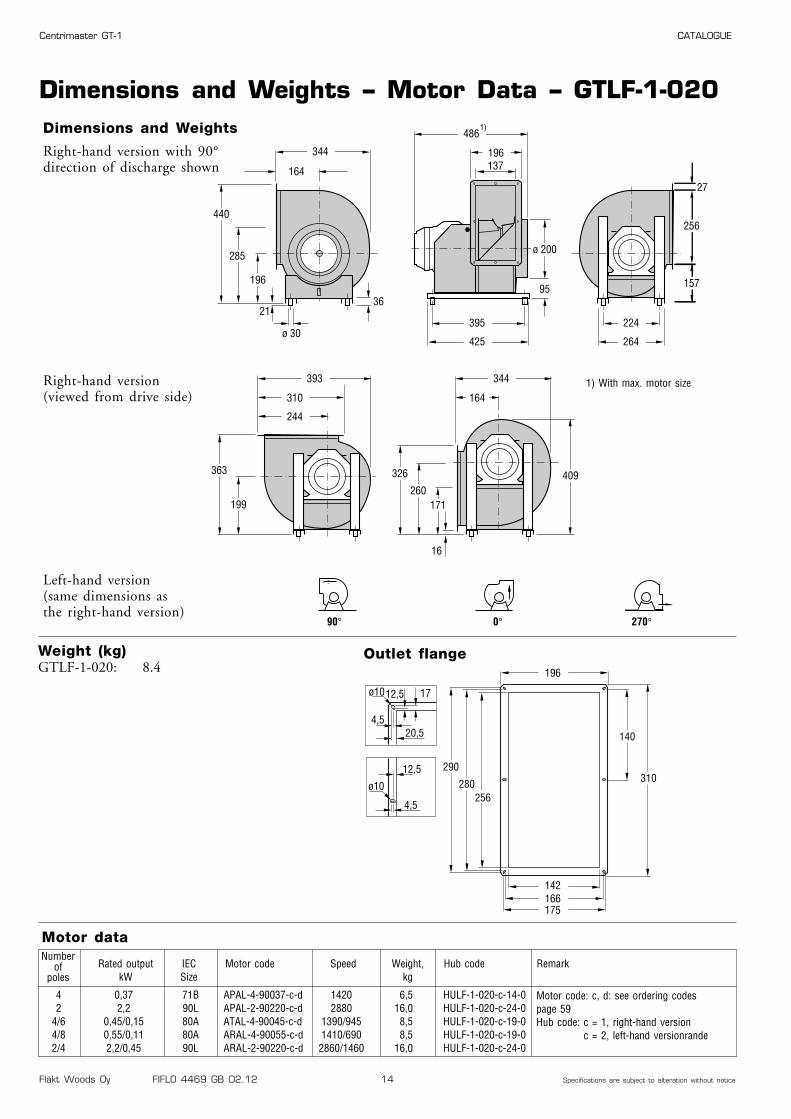
4 0,37 71B APAL-4-90037-c-d 1420 6,5 HULF-1-020-c-14-02 2,2 90L APAL-2-90220-c-d 2880 16,0 HULF-1-020-c-24-0
4/6 0,45/0,15 80A ATAL-4-90045-c-d 1390/945 8,5 HULF-1-020-c-19-04/8 0,55/0,11 80A ARAL-4-90055-c-d 1410/690 8,5 HULF-1-020-c-19-02/4 2,2/0,45 90L ARAL-2-90220-c-d 2860/1460 16,0 HULF-1-020-c-24-0
Dimensions and Weights – Motor Data – GTLF-1-020Dimensions and Weights
Motor data
Right-hand version with 90°direction of discharge shown
Right-hand version (viewed from drive side)
Left-hand version (same dimensions as the right-hand version)
196
142166
290
280256
175
310
140
ø10
ø10
4,5
12,5
12,5
20,5
4,5
17
Outlet flange
344
164 137
ø 30
2136
16
27
486
196
ø 200
256
15795
395
425
224
264
440
285
196
393 344
409
310 164
244
363
199
326
260171
90° 0° 270°
1)
Numberof
polesRated output
kWIECSize
Motor code Speed Weight,kg
Weight (kg) GTLF-1-020: 8.4
Hub code
Motor code: c, d: see ordering codespage 59Hub code: c = 1, right-hand version
c = 2, left-hand versionrande
Remark
1) With max. motor size
Fläkt Woods Oy FIFLO 4469 GB 02.12 15 Specifications are subject to alteration without notice
Centrimaster GT-1 CATALOGUE
15
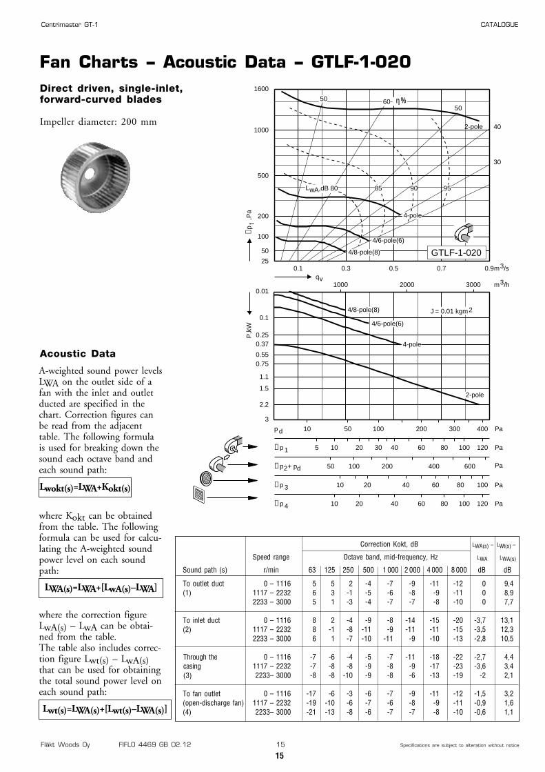
Direct driven, single-inlet,forward-curved blades
Impeller diameter: 200 mm
Fan Charts – Acoustic Data – GTLF-1-020
0.1 0.3 0.5 0.7 0.925
50
100
200
500
1000
1600
0.01
0.1
0.250.37
0.550.75
1.1
1.5
2.2
3
1000 2000 3000
10 50 100 200 300 400p d Pa
50 100 200 400 600∆p2+ pd Pa
10 20 40 60 80 100∆p 3 Pa
5 10 20 30 40 60 80 100 120∆p 1 Pa
10 20 40 60 80 100 120∆p 4 Pa
30
40
506050
4/8-pole(8)
4/6-pole(6)
4/8-pole(8)
qvm3/h
m3/s
J = 0.01 kgm2
∆pt
,Pa
P,k
W
9085 95
2-pole
4-pole
2-pole
4/6-pole(6)
4-pole
,dB 80LwA
GTLF-1-020
η%
Correction Kokt, dB LWA(s) – LWt(s) –
Speed range Octave band, mid-frequency, Hz LWA LWA(s)
Sound path (s) r/min 63 125 250 500 1 000 2 000 4 000 8 000 dB dB
To outlet duct 0 – 1116 5 5 2 -4 -7 -9 -11 -12 0 9,4(1) 1117 – 2232 6 3 -1 -5 -6 -8 -9 -11 0 8,9
2233 – 3000 5 1 -3 -4 -7 -7 -8 -10 0 7,7
To inlet duct 0 – 1116 8 2 -4 -9 -8 -14 -15 -20 -3,7 13,1(2) 1117 – 2232 8 -1 -8 -11 -9 -11 -11 -15 -3,5 12,3
2233 – 3000 6 1 -7 -10 -11 -9 -10 -13 -2,8 10,5
Through the vid 0 – 1116 -7 -6 -4 -5 -7 -11 -18 -22 -2,7 4,4kanalansluten fläkt 1117 – 2232 -7 -8 -8 -9 -8 -9 -17 -23 -3,6 3,4(3) 2233– 3000 -8 -8 -10 -9 -8 -6 -13 -19 -2 2,1
To fan outlet 0 – 1116 -17 -6 -3 -6 -7 -9 -11 -12 -1,5 3,2(open-discharge fan) 1117 – 2232 -19 -10 -6 -7 -6 -8 -9 -11 -0,9 1,6(4) 2233– 3000 -21 -13 -8 -6 -7 -7 -8 -10 -0,6 1,1
Through thecasing(3)
A-weighted sound power levelsLWA on the outlet side of afan with the inlet and outletducted are specified in thechart. Correction figures canbe read from the adjacenttable. The following formulais used for breaking down thesound each octave band andeach sound path:
where Kokt can be obtainedfrom the table. The followingformula can be used for calcu-lating the A-weighted soundpower level on each soundpath:
where the correction figureLwA(s) – LwA can be obtai-ned from the table.The table also includes correc-tion figure Lwt(s) – LwA(s)that can be used for obtainingthe total sound power level oneach sound path:
Lwokt(s)=LWA+Kokt(s)
Acoustic Data
LWA(s)=LWA+[LwA(s)–LWA]
Lwt(s)=LWA(s)+[Lwt(s)–LWA(s)]

Fläkt Woods Oy FIFLO 4469 GB 02.12 16 Specifications are subject to alteration without notice
Centrimaster GT-1 CATALOGUE
Dimensions and Weights – Motor Data – GTLF-1-022
4 0,55 80A APAL-4-90055-c-d 1390 9,0 HULF-1-022-c-19-02 2,2 90L APAL-2-90220-c-d 2880 16,0 HULF-1-022-c-24-0
4/6 0,75/0,22 80B ATAL-4-90075-c-d 1400/955 10,5 HULF-1-022-c-19-04/8 0,55/0,11 80A ARAL-4-90055-c-d 1410/690 9,0 HULF-1-022-c-19-0
Dimensions and Weights
Motor data
Right-hand version with 90°direction of discharge shown
Right-hand version (viewed from drive side)
Left-hand version (same dimensions as the right-hand version)
219
159189
328
318288
198
348
159
ø10
ø10
5
15
10
15
5
20
Outlet flange
382
180 154
ø 30
36
15
30
505
219
ø 220
288
168101
417
447
224
264
486
312
212
441 382
456
348 180
274
399
219
363
289189
90° 0° 270°
21
1)
Numberof
polesRated output
kWIECSize
Motor code Speed Weight,kg
Weight (kg) GTLF-1-022: 9,8
Hub code
Motor code: c, d: see ordering codespage 59Hub code: c = 1, right-hand version
c = 2, left-hand versionrande
Remark
1) With max. motor size
Fläkt Woods Oy FIFLO 4469 GB 02.12 17 Specifications are subject to alteration without notice
Centrimaster GT-1 CATALOGUE
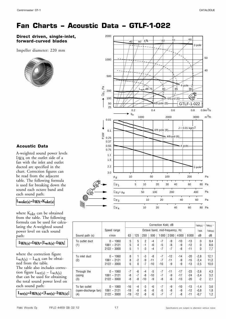
Fan Charts – Acoustic Data – GTLF-1-022Direct driven, single-inlet,forward-curved blades
Impeller diameter: 220 mm
0.2 0.4 0.6 0.8 0.92550
100
200
500
1000
2000
0.01
0.1
0.250.37
0.550.75
1.1
1.5
2.2
3.0
1000 2000 3000
10 50 100 200p d Pa
50 100 200 400∆p2+ pd Pa
10 20 40 60∆p 3 Pa
5 10 20 30 40 60 80∆p 1 Pa
10 20 40 60 80∆p 4 Pa
40
50
6061605040
2-pole
qvm3/h
m3/s
J = 0.01 kgm2
∆pt
,Pa
P,k
W
8580 904-pole
2-pole
,dB 75LwA
4/8-pole (8)
4/8-pole (8)
4/6-pol (6)
4/6-pol (6)
4-pole
GTLF-1-022
η%
Correction Kokt, dB LWA(s) – LWt(s) –
Speed range Octave band, mid-frequency, Hz LWA LWA(s)
Sound path (s) r/min 63 125 250 500 1 000 2 000 4 000 8 000 dB dB
To outlet duct 0 – 1060 5 5 2 -4 -7 -9 -10 -13 0 9,4(1) 1061 – 2121 5 4 -1 -6 -5 -8 -9 -12 0 8,6
2122 – 3000 5 1 -3 -4 -7 -7 -8 -11 0 7,7
To inlet duct 0 – 1060 8 1 -3 -8 -7 -12 -14 -20 -2,8 12,1(2) 1061 – 2121 8 -2 -9 -11 -7 -11 -9 -15 -2,4 11,2
2122 – 3000 6 0 -7 -10 -10 -9 -9 -13 -2,5 10,0
Through the 0 – 1060 -7 -6 -4 -5 -7 -11 -17 -23 -2,6 4,3casing 1061 – 2121 -8 -7 -8 -10 -7 -9 -17 -24 -3,4 3,2(3) 2122 – 3000 -8 -8 -10 -9 -8 -6 -13 -20 -2 2,1
To fan outlet 0 – 1060 -16 -4 -3 -6 -7 -9 -10 -13 -1,4 3,6(open-discharge fan) 1061 – 2121 -18 -8 -6 -8 -5 -8 -9 -12 -0,8 1,8(4) 2122 – 3000 -19 -12 -8 -6 -7 -7 -8 -11 -0,7 1,2
A-weighted sound power levelsLWA on the outlet side of afan with the inlet and outletducted are specified in thechart. Correction figures canbe read from the adjacenttable. The following formulais used for breaking down thesound each octave band andeach sound path:
where Kokt can be obtainedfrom the table. The followingformula can be used for calcu-lating the A-weighted soundpower level on each soundpath:
where the correction figureLwA(s) – LwA can be obtai-ned from the table.The table also includes correc-tion figure Lwt(s) – LwA(s)that can be used for obtainingthe total sound power level oneach sound path:
Lwokt(s)=LWA+Kokt(s)
Acoustic Data
LWA(s)=LWA+[LwA(s)–LWA]
Lwt(s)=LWA(s)+[Lwt(s)–LWA(s)]

Fläkt Woods Oy FIFLO 4469 GB 02.12 18 Specifications are subject to alteration without notice
Centrimaster GT-1 CATALOGUE
Dimensions and Weights – Motor Data – GTLB-1-022
4 0,25 71A APAL-4-90025-c-d 1410 5,5 HULB-1-022-c-14-02 0,37 71A APAL-2-90037-c-d 2840 5,5 HULB-1-022-c-14-0
4/6 0,3/0,1 71B ATAL-4-90030-c-d 1350/900 6,5 HULB-1-022-c-14-04/8 0,37/0,09 71B ARAL-4-90037-c-d 1360/700 6,5 HULB-1-022-c-14-02/4 0,55/0,12 71B ARAL-2-90055-c-d 2700/1470 6,5 HULB-1-022-c-14-0
Dimensions and Weights
Motor data
Right-hand version with 90°direction of discharge shown
Right-hand version (viewed from drive side)
Left-hand version (same dimensions as the right-hand version)
219
159189
328
318288
198
348
159
ø10
ø10
5
15
10
15
5
20
Outlet flange
382
180 154
ø 30
36
15
30
505
219
ø 220
288
168101
417
447
224
264
486
312
212
441 382
456
348 180
274
399
219
363
289189
90° 0° 270°
21
1)
Numberof
polesRated output
kWIECSize
Motor code Speed Weight,kg
Weight (kg) GTLB-1-022: 10,7
Hub code
Motor code: c, d: see ordering codespage 59Hub code: c = 1, right-hand version
c = 2, left-hand versionrande
Remark
1) With max. motor size

Fläkt Woods Oy FIFLO 4469 GB 02.12 19 Specifications are subject to alteration without notice
Centrimaster GT-1 CATALOGUE
Fan Charts – Acoustic Data – GTLB-1-022Direct driven, single-inlet,backward-curved blades
Impeller diameter: 220 mm
Enbart GTLB finns i brandgas-utförande
0.02
0.04
0.060.08
0 0.1 0.2 0.3 0.4 0.450
50
100
200
500
700
0
0.1
0.15
0.2
500 1000 1500
10 20 60p d Pa
40∆p2+ pd Pa
10∆p 3 Pa
5 10 15 20∆p 1 Pa
10∆p 4 Pa
50
60
70
75
787570
η%
2-pole
4-pole
4/8-pole(8)
4/6-pole(6)
qvm3/h
m3/s
J = 0.03 kgm2
∆pt
,Pa
P,k
W
2-pole
4-pole
4/8-pole(8)4/6-pole(6)
67
7570 80,dB 65LwA
0.01
GTLB-1-022
Correction Kokt, dB LWA(s) – LWt(s) –
Speed range Octave band, mid-frequency, Hz LWA LWA(s)
Sound path (s) r/min 63 125 250 500 1 000 2 000 4 000 8 000 dB dB
To outlet duct 0 – 1928 2 2 3 -4 -6 -9 -12 -16 0 7,8(1) 1929 – 3000 2 -1 -5 -1 -6 -8 -12 -16 0 5,9
To inlet duct 0 – 1928 4 1 2 -4 -6 -9 -12 -16 -0,2 8,1(2) 1929 – 3000 1 -2 -6 0 -4 -9 -11 -16 0,9 4,9
Through the 0 – 1928 -6 -5 -3 -9 -11 -15 -20 -31 -5,7 6,9casing 1929 – 3000 -6 -8 -9 -7 -12 -15 -23 -35 -6,4 5,6(3)
To fan outlet 0 – 1928 -15 -7 -2 -6 -6 -9 -12 -16 -1,4 3,4(open-discharge fan) 1929 – 3000 -19 -11 -10 -3 -6 -8 -12 -16 -0,9 1,7(4)
A-weighted sound power levelsLWA on the outlet side of afan with the inlet and outletducted are specified in thechart. Correction figures canbe read from the adjacenttable. The following formulais used for breaking down thesound each octave band andeach sound path:
where Kokt can be obtainedfrom the table. The followingformula can be used for calcu-lating the A-weighted soundpower level on each soundpath:
where the correction figureLwA(s) – LwA can be obtai-ned from the table.The table also includes correc-tion figure Lwt(s) – LwA(s)that can be used for obtainingthe total sound power level oneach sound path:
Lwokt(s)=LWA+Kokt(s)
Acoustic Data
LWA(s)=LWA+[LwA(s)–LWA]
Lwt(s)=LWA(s)+[Lwt(s)–LWA(s)]

Fläkt Woods Oy FIFLO 4469 GB 02.12 20 Specifications are subject to alteration without notice
Centrimaster GT-1 CATALOGUE
Dimensions and Weights – Motor Data – GTLF-1-025
4 1,1 90S APAL-4-90110-c-d 1410 13,0 HULF-1-025-c-24-06 0,37 80A APAL-6-90037-c-d 915 9,0 HULF-1-025-c-19-0
4/6 1,5/0,45 90L ATAL-4-90150-c-d 1400/930 16,0 HULF-1-025-c-24-04/8 1,1/0,26 90S ARAL-4-90110-c-d 1410/700 13,0 HULF-1-025-c-24-0
Dimensions and Weights
Motor data
Right-hand version with 90°direction of discharge shown
Right-hand version (viewed from drive side)
Left-hand version (same dimensions as the right-hand version)
239
179209
362
352322
219
382
2 x 176
ø10
ø10
15
15
15
19,5
4,5
19,5
Outlet flange
419
195 174
ø 30
36
13
30
549
239
ø 244
322
174102
463
493
244
284
526
335
225
486 419
499
380 195
301
437
242
395
314204
90° 0° 270°
21
1)
Numberof
polesRated output
kWIECSize
Motor code Speed Weight,kg
Weight (kg) GTLF-1-025: 12,9
Hub code
Motor code: c, d: see ordering codespage 59Hub code: c = 1, right-hand version
c = 2, left-hand versionrande
Remark
1) With max. motor size
Fläkt Woods Oy FIFLO 4469 GB 02.12 21 Specifications are subject to alteration without notice
Centrimaster GT-1 CATALOGUE
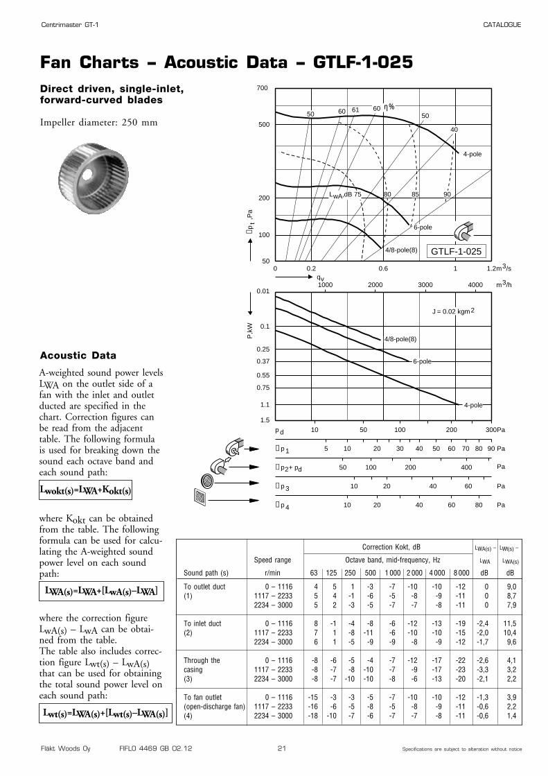
Fan Charts – Acoustic Data – GTLF-1-025Direct driven, single-inlet,forward-curved blades
Impeller diameter: 250 mm
0 0.2 0.6 1 1.250
100
200
500
700
0.01
0.1
0.25
0.37
0.55
0.75
1.1
1.5
1000 2000 3000 4000
10 50 100 200 300p d Pa
50 100 200 400∆p2+ pd Pa
10 20 40 60∆p 3 Pa
5 10 20 30 40 50 60 70 80 90∆p 1 Pa
10 20 40 60 80∆p 4 Pa
40
5060616050
6-pole
4-pole
4/8-pole(8)
6-pole
4-pole
4/8-pole(8)
qvm3/h
m3/s
J = 0.02 kgm2
∆pt
,Pa
P,k
W
8580 90,dB 75LwA
GTLF-1-025
η%
Correction Kokt, dB LWA(s) – LWt(s) –
Speed range Octave band, mid-frequency, Hz LWA LWA(s)
Sound path (s) r/min 63 125 250 500 1 000 2 000 4 000 8 000 dB dB
To outlet duct 0 – 1116 4 5 1 -3 -7 -10 -10 -12 0 9,0(1) 1117 – 2233 5 4 -1 -6 -5 -8 -9 -11 0 8,7
2234 – 3000 5 2 -3 -5 -7 -7 -8 -11 0 7,9
To inlet duct 0 – 1116 8 -1 -4 -8 -6 -12 -13 -19 -2,4 11,5(2) 1117 – 2233 7 1 -8 -11 -6 -10 -10 -15 -2,0 10,4
2234 – 3000 6 1 -5 -9 -9 -8 -9 -12 -1,7 9,6
Through the 0 – 1116 -8 -6 -5 -4 -7 -12 -17 -22 -2,6 4,1casing 1117 – 2233 -8 -7 -8 -10 -7 -9 -17 -23 -3,3 3,2(3) 2234 – 3000 -8 -7 -10 -10 -8 -6 -13 -20 -2,1 2,2
To fan outlet 0 – 1116 -15 -3 -3 -5 -7 -10 -10 -12 -1,3 3,9(open-discharge fan) 1117 – 2233 -16 -6 -5 -8 -5 -8 -9 -11 -0,6 2,2(4) 2234 – 3000 -18 -10 -7 -6 -7 -7 -8 -11 -0,6 1,4
A-weighted sound power levelsLWA on the outlet side of afan with the inlet and outletducted are specified in thechart. Correction figures canbe read from the adjacenttable. The following formulais used for breaking down thesound each octave band andeach sound path:
where Kokt can be obtainedfrom the table. The followingformula can be used for calcu-lating the A-weighted soundpower level on each soundpath:
where the correction figureLwA(s) – LwA can be obtai-ned from the table.The table also includes correc-tion figure Lwt(s) – LwA(s)that can be used for obtainingthe total sound power level oneach sound path:
Lwokt(s)=LWA+Kokt(s)
Acoustic Data
LWA(s)=LWA+[LwA(s)–LWA]
Lwt(s)=LWA(s)+[Lwt(s)–LWA(s)]

Fläkt Woods Oy FIFLO 4469 GB 02.12 22 Specifications are subject to alteration without notice
Centrimaster GT-1 CATALOGUE
Dimensions and Weights – Motor Data – GTLB-1-025
4 0,25 71A APAL-4-90025-c-d 1410 5,5 HULB-1-025-c-14-02 0,55 71B APAL-2-90055-c-d 2830 5,5 HULB-1-025-c-14-0
4/6 0,3/0,1 71B ATAL-4-90030-c-d 1350/900 6,5 HULB-1-025-c-14-04/8 0,37/0,09 71B ARAL-4-90037-c-d 1360/700 6,5 HULB-1-025-c-14-02/4 0,55/0,12 71B ARAL-2-90055-c-d 2700/1470 6,5 HULB-1-025-c-14-0
Dimensions and Weights
Motor data
Right-hand version with 90°direction of discharge shown
Right-hand version (viewed from drive side)
Left-hand version (same dimensions as the right-hand version)
239
179209
362
352322
219
382
2 x 176
ø10
ø10
15
15
15
19,5
4,5
19,5
Outlet flange
419
195 174
ø 30
36
13
30
549
239
ø 244
322
174102
463
493
244
284
526
335
225
486 419
499
380 195
301
437
242
395
314204
90° 0° 270°
21
1)
Numberof
polesRated output
kWIECSize
Motor code Speed Weight,kg
Weight (kg) GTLB-1-025: 13,4
Hub code
Motor code: c, d: see ordering codespage 59Hub code: c = 1, right-hand version
c = 2, left-hand versionrande
Remark
1) With max. motor size

Fläkt Woods Oy FIFLO 4469 GB 02.12 23 Specifications are subject to alteration without notice
Centrimaster GT-1 CATALOGUE
Fan Charts – Acoustic Data – GTLB-1-025Direct driven, single-inlet,backward-curved blades
Impeller diameter: 250 mm
Only the GTLB is available inthe smoke extraction version.
0.01
0.02
0.06
0 0.2 0.4 0.6 0.7
50
100
200
500
1000
0
0.1
0.2
0.3
0.4
500 1000 1500 2000 2500
10 20 60 80 100p d Pa
40 100∆p2+ pd Pa
10 20∆p 3 Pa
5 10 15 20 25 30∆p 1 Pa
10 20∆p 4 Pa
40
60
70
75
78757067
η%
4-pole
2-pole
4/6-pole(6(4/8-pole(8)
qvm3/h
m3/s
J = 0.03 kgm2
∆pt
,Pa
P,k
W
4-pole
2-pole
4/6-pole(6)4/8-pole(8)
,dB 70 75 80 85LwA
GTLB-1-025
Correction Kokt, dB LWA(s) – LWt(s) –
Speed range Octave band, mid-frequency, Hz LWA LWA(s)
Sound path (s) r/min 63 125 250 500 1 000 2 000 4 000 8 000 dB dB
To outlet duct 0 – 1928 1 2 3 -4 -7 -8 -13 -16 0 7,5(1) 1929 – 3000 -2 0 -7 0 -7 -10 -12 -15 0 5,1
To inlet duct 0 – 1928 1 2 3 -4 -5 -10 -13 -18 0 7,6(2) 1929 – 3000 -1 0 -8 0 -5 -11 -12 -17 0,3 5,1
Through the 0 – 1928 -7 -5 -4 -9 -12 -14 -21 -31 -6,1 6,7casing 1929 – 3000 -11 -10 -10 -8 -11 -18 -23 -34 -7 4,3(3)
To fan outlet 0 – 1928 -16 -6 -1 -5 -7 -8 -13 -16 -1,3 3,9(open-discharge fan) 1929 – 3000 -21 -9 -11 -1 -7 -10 -12 -15 -0,8 2,3(4)
A-weighted sound power levelsLWA on the outlet side of afan with the inlet and outletducted are specified in thechart. Correction figures canbe read from the adjacenttable. The following formulais used for breaking down thesound each octave band andeach sound path:
where Kokt can be obtainedfrom the table. The followingformula can be used for calcu-lating the A-weighted soundpower level on each soundpath:
where the correction figureLwA(s) – LwA can be obtai-ned from the table.The table also includes correc-tion figure Lwt(s) – LwA(s)that can be used for obtainingthe total sound power level oneach sound path:
Lwokt(s)=LWA+Kokt(s)
Acoustic Data
LWA(s)=LWA+[LwA(s)–LWA]
Lwt(s)=LWA(s)+[Lwt(s)–LWA(s)]

Fläkt Woods Oy FIFLO 4469 GB 02.12 24 Specifications are subject to alteration without notice
Centrimaster GT-1 CATALOGUE
Dimensions and Weights – Motor Data – GTLF-1-028
4 1,5 90L APAL-4-90150-c-d 1420 16,0 HULF-1-028-c-24-06 0,55 80B APAL-6-90055-c-d 900 10,0 HULF-1-028-c-19-0
4/6 1,5/0,45 90L ATAL-4-90150-c-d 1400/930 16,0 HULF-1-028-c-24-04/8 1,7/0,35 90L ARAL-4-90170-c-d 1390/700 16,0 HULF-1-028-c-24-0
Dimensions and Weights
Motor data
Right-hand version with 90°direction of discharge shown
Right-hand version (viewed from drive side)
Left-hand version (same dimensions as the right-hand version)
257
197227
400
391361
236
421
200,5
ø10
ø10
4,5
15
10,5
15
4,5
10,5
Outlet flange
466
215 192
ø 30
36
10
30
567
257
ø 275
361
190110
484
514
244
284
581
371
248
541 466
551
421 215
333
482
267
431
343221
90° 0° 270°
21
1)
Numberof
polesRated output
kWIECSize
Motor code Speed Weight,kg
Weight (kg) GTLF-1-028: 15,2
Hub code
Motor code: c, d: see ordering codespage 59Hub code: c = 1, right-hand version
c = 2, left-hand versionrande
Remark
1) With max. motor size
Fläkt Woods Oy FIFLO 4469 GB 02.12 25 Specifications are subject to alteration without notice
Centrimaster GT-1 CATALOGUE
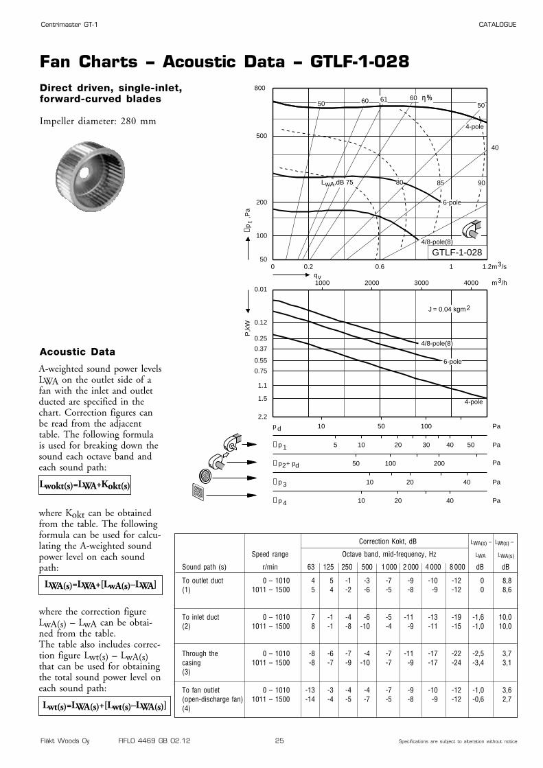
Fan Charts – Acoustic Data – GTLF-1-028Direct driven, single-inlet,forward-curved blades
Impeller diameter: 280 mm
0 0.2 0.6 1 1.250
100
200
500
800
0.01
0.12
0.25
0.37
0.55
0.75
1.1
1.5
2.2
1000 2000 3000 4000
10 50 100p d Pa
50 100 200∆p2+ pd Pa
10 20 40∆p 3 Pa
5 10 20 30 40 50∆p 1 Pa
10 20 40∆p 4 Pa
40
5060616050
4/8-pole(8)
qvm3/h
m3/s
J = 0.04 kgm2
∆pt
,Pa
P,k
W
,dB 75 80 85 90
6-pole
4-pole
6-pole
4-pole
4/8-pole(8)
LwA
GTLF-1-028
η%
Correction Kokt, dB LWA(s) – LWt(s) –
Speed range Octave band, mid-frequency, Hz LWA LWA(s)
Sound path (s) r/min 63 125 250 500 1 000 2 000 4 000 8 000 dB dB
To outlet duct 0 – 1010 4 5 -1 -3 -7 -9 -10 -12 0 8,8(1) 1011 – 1500 5 4 -2 -6 -5 -8 -9 -12 0 8,6
To inlet duct 0 – 1010 7 -1 -4 -6 -5 -11 -13 -19 -1,6 10,0(2) 1011 – 1500 8 -1 -8 -10 -4 -9 -11 -15 -1,0 10,0
Through the 0 – 1010 -8 -6 -7 -4 -7 -11 -17 -22 -2,5 3,7casing 1011 – 1500 -8 -7 -9 -10 -7 -9 -17 -24 -3,4 3,1(3)
To fan outlet 0 – 1010 -13 -3 -4 -4 -7 -9 -10 -12 -1,0 3,6(open-discharge fan) 1011 – 1500 -14 -4 -5 -7 -5 -8 -9 -12 -0,6 2,7(4)
A-weighted sound power levelsLWA on the outlet side of afan with the inlet and outletducted are specified in thechart. Correction figures canbe read from the adjacenttable. The following formulais used for breaking down thesound each octave band andeach sound path:
where Kokt can be obtainedfrom the table. The followingformula can be used for calcu-lating the A-weighted soundpower level on each soundpath:
where the correction figureLwA(s) – LwA can be obtai-ned from the table.The table also includes correc-tion figure Lwt(s) – LwA(s)that can be used for obtainingthe total sound power level oneach sound path:
Lwokt(s)=LWA+Kokt(s)
Acoustic Data
LWA(s)=LWA+[LwA(s)–LWA]
Lwt(s)=LWA(s)+[Lwt(s)–LWA(s)]

Fläkt Woods Oy FIFLO 4469 GB 02.12 26 Specifications are subject to alteration without notice
Centrimaster GT-1 CATALOGUE
Dimensions and Weights – Motor Data – GTLB-1-028
4 0,25 71A APAL-4-90025-c-d 1410 5,5 HULB-1-028-c-14-02 0,75 80A APAL-2-90075-c-d 2870 9,0 HULB-1-028-c-19-0
4/6 0,3/0,1 71B ATAL-4-90030-c-d 1350/900 6,5 HULB-1-028-c-14-04/8 0,37/0,09 71B ARAL-4-90037-c-d 1360/700 6,5 HULB-1-028-c-14-02/4 0,75/0,15 80A ARAL-2-90075-c-d 2850/1430 9,0 HULB-1-028-c-19-0
Dimensions and Weights
Motor data
Right-hand version with 90°direction of discharge shown
Right-hand version (viewed from drive side)
Left-hand version (same dimensions as the right-hand version)
257
197227
400
391361
236
421
200,5
ø10
ø10
4,5
15
10,5
15
4,5
10,5
Outlet flange
466
215 192
ø 30
36
10
30
567
257
ø 275
361
190110
484
514
244
284
581
371
248
541 466
551
421 215
333
482
267
431
343221
90° 0° 270°
21
1)
Numberof
polesRated output
kWIECSize
Motor code Speed Weight,kg
Weight (kg) GTLB-1-028: 14,9
Hub code
Motor code: c, d: see ordering codespage 59Hub code: c = 1, right-hand version
c = 2, left-hand versionrande
Remark
1) With max. motor size

Fläkt Woods Oy FIFLO 4469 GB 02.12 27 Specifications are subject to alteration without notice
Centrimaster GT-1 CATALOGUE
Fan Charts – Acoustic Data – GTLB-1-028Direct driven, single-inlet,backward-curved blades
Impeller diameter: 280 mm
Only the GTLB is available inthe smoke extraction version.
0.010.02
0.06
0 0.2 0.4 0.6 0.8 1
50
100
200
500
1000
0
0.1
0.2
0.4
0.6
0.8
500 1000 1500 2000 2500 3000 3500
10 20 60 80 100 120p d Pa
40 100∆p2+ pd Pa
10 20∆p 3 Pa
5 10 15 20 25 30 35∆p 1 Pa
10 20 30∆p 4 Pa
40
60
70
75
797570
η%
2-pole
4-pole
4/6-pole(6)4/8-pole(8)
qvm3/h
m3/s
J = 0.06 kgm2
∆pt
,Pa
P,k
W
2-pole
4-pole4/6-pole(6)
4/8-pole(8)
75 80 85
66
,dB 70LwA
GTLB-1-028
Correction Kokt, dB LWA(s) – LWt(s) –
Speed range Octave band, mid-frequency, Hz LWA LWA(s)
Sound path (s) r/min 63 125 250 500 1 000 2 000 4 000 8 000 dB dB
To outlet duct 0 – 1928 1 2 3 -4 -7 -8 -13 -16 0 7,6(1) 1929 – 3000 -1 -1 -7 -1 -6 -8 -12 -16 0 4,9
To inlet duct 0 – 1928 1 1 3 -2 -5 -10 -12 -17 0,6 6,9(2) 1929 – 3000 -2 -2 -8 0 -4 -10 -11 -17 0,7 4,1
Through the 0 – 1928 -7 -5 -4 -9 -12 -14 -21 -31 -6,1 6,7casing 1929 – 3000 -9 -8 -10 -8 -12 -15 -23 -35 -6,9 5,0(3)
To fan outlet 0 – 1928 -14 -5 0 -5 -7 -8 -13 -16 -1,1 4,3(open-discharge fan) 1929 – 3000 -20 -9 -10 -2 -6 -8 -12 -16 -0,5 1,9(4)
A-weighted sound power levelsLWA on the outlet side of afan with the inlet and outletducted are specified in thechart. Correction figures canbe read from the adjacenttable. The following formulais used for breaking down thesound each octave band andeach sound path:
where Kokt can be obtainedfrom the table. The followingformula can be used for calcu-lating the A-weighted soundpower level on each soundpath:
where the correction figureLwA(s) – LwA can be obtai-ned from the table.The table also includes correc-tion figure Lwt(s) – LwA(s)that can be used for obtainingthe total sound power level oneach sound path:
Lwokt(s)=LWA+Kokt(s)
Acoustic Data
LWA(s)=LWA+[LwA(s)–LWA]
Lwt(s)=LWA(s)+[Lwt(s)–LWA(s)]

Fläkt Woods Oy FIFLO 4469 GB 02.12 28 Specifications are subject to alteration without notice
Centrimaster GT-1 CATALOGUE
Dimensions and Weights – Motor Data – GTLF-1-031
4 3 100LB APAL-4-90300-c-d 1430 24,0 HULF-1-031-c-28-06 1,1 90L APAL-6-90110-c-d 930 16,0 HULF-1-031-c-24-08 0,55 90L APAL-8-90055-c-d 690 16,0 HULF-1-031-c-24-0
4/6 3/1 112M ATAL-4-00300-c-d 1445/975 33,0 HULF-1-031-c-28-04/8 2,8/0,6 100LB ARAL-4-90280-c-d 1430/720 23,0 HULF-1-031-c-28-0
Dimensions and Weights
Motor data
Right-hand version with 90°direction of discharge shown
Right-hand version (viewed from drive side)
Left-hand version (same dimensions as the right-hand version)
277
217247
444
434404
257
464
2 x 217
ø10
ø10
15
15
15
19,5
4,5
19,5
Outlet flange
518
236 212
ø 30
36
13
30
591
277
ø 310
404
212119
507
537
280
320
646
414
275
604 518
617
464 236
371
533
297
477
384245
90° 0° 270°
21
1)
Numberof
polesRated output
kWIECSize
Motor code Speed Weight,kg
Weight (kg) GTLF-1-031: 17,7
Hub code
Motor code: c, d: see ordering codespage 59Hub code: c = 1, right-hand version
c = 2, left-hand versionrande
Remark
1) With max. motor size

Fläkt Woods Oy FIFLO 4469 GB 02.12 29 Specifications are subject to alteration without notice
Centrimaster GT-1 CATALOGUE
Fan Charts – Acoustic Data – GTLF-1-031Direct driven, single-inlet,forward-curved blades
Impeller diameter: 310 mm95
0 0.2 0.6 1 1.4 1.8 250
100
200
500
1000
50 100 200 400∆p2+ pd Pa
10 20 40 60 80∆p 3 Pa
5 10 20 30 40 50 60 80 100∆p 1 Pa
10 20 40 60 80 100∆p 4 Pa
40
5060 6460
qv
m3/s
∆pt
,Pa
,dB 75
85
90
LwA
80
0.05
0.12
0.250.37
0.550.75
1.1
1.5
2.2
3
4
2000 3000 4000 5000 6000 7000
10 50 100 200 300p d Pa
m3/h
J = 0.05 kgm2
P,k
W
4-pole
4-pole
6-pole
8-pole
8-pole
6-pole
GTLF-1-031
η%
Correction Kokt, dB LWA(s) – LWt(s) –
Speed range Octave band, mid-frequency, Hz LWA LWA(s)
Sound path (s) r/min 63 125 250 500 1 000 2 000 4 000 8 000 dB dB
To outlet duct 0 – 1010 3 4 -2 -2 -7 -9 -10 -11 0 8,0(1) 1011 – 1500 5 4 -2 -6 -5 -8 -9 -13 0 8,6
To inlet duct 0 – 1010 7 -3 -6 -5 -4 -10 -12 -19 -0,8 9,0(2) 1011 – 1500 7 -1 -7 -9 -3 -8 -10 -15 -0,1 8,5
Through the 0 – 1010 -9 -6 -4 -3 -7 -11 -17 -21 -1,9 3,9casing 1011 – 1500 -8 -7 -6 -10 -7 -9 -17 -25 -3,3 3,5(3)
To fan outlet 0 – 1010 -13 -3 -5 -3 -7 -9 -10 -11 -0,7 3,4(open-discharge fan) 1011 – 1500 -12 -4 -5 -7 -5 -8 -9 -13 -0,6 2,7(4)
A-weighted sound power levelsLWA on the outlet side of afan with the inlet and outletducted are specified in thechart. Correction figures canbe read from the adjacenttable. The following formulais used for breaking down thesound each octave band andeach sound path:
where Kokt can be obtainedfrom the table. The followingformula can be used for calcu-lating the A-weighted soundpower level on each soundpath:
where the correction figureLwA(s) – LwA can be obtai-ned from the table.The table also includes correc-tion figure Lwt(s) – LwA(s)that can be used for obtainingthe total sound power level oneach sound path:
Lwokt(s)=LWA+Kokt(s)
Acoustic Data
LWA(s)=LWA+[LwA(s)–LWA]
Lwt(s)=LWA(s)+[Lwt(s)–LWA(s)]

Fläkt Woods Oy FIFLO 4469 GB 02.12 30 Specifications are subject to alteration without notice
Centrimaster GT-1 CATALOGUE
Dimensions and Weights – Motor Data – GTLB-1-031
4 0,25 71A APAL-4-90025-c-d 1410 5,5 HULB-1-031-c-14-02 1,5 90S APAL-2-90150-c-d 2870 13,0 HULB-1-031-c-24-0
4/6 0,3/0,1 71B ATAL-4-90030-c-d 1350/900 6,5 HULB-1-031-c-14-04/8 0,37/0,09 71B ARAL-4-90037-c-d 1360/700 6,5 HULB-1-031-c-14-02/4 1,5/0,33 90S ARAL-2-90150-c-d 2860/1460 13,0 HULB-1-031-c-24-0
Dimensions and Weights
Motor data
Right-hand version with 90°direction of discharge shown
Right-hand version (viewed from drive side)
Left-hand version (same dimensions as the right-hand version)
277
217247
444
434404
257
464
2 x 217
ø10
ø10
15
15
15
19,5
4,5
19,5
Outlet flange
518
236 212
ø 30
36
13
30
591
277
ø 310
404
212119
507
537
280
320
646
414
275
604 518
617
464 236
371
533
297
477
384245
90° 0° 270°
21
1)
Numberof
polesRated output
kWIECSize
Motor code Speed Weight,kg
Weight (kg) GTLB-1-031: 18,0
Hub code
Motor code: c, d: see ordering codespage 59Hub code: c = 1, right-hand version
c = 2, left-hand versionrande
Remark
1) With max. motor size
Fläkt Woods Oy FIFLO 4469 GB 02.12 31 Specifications are subject to alteration without notice
Centrimaster GT-1 CATALOGUE
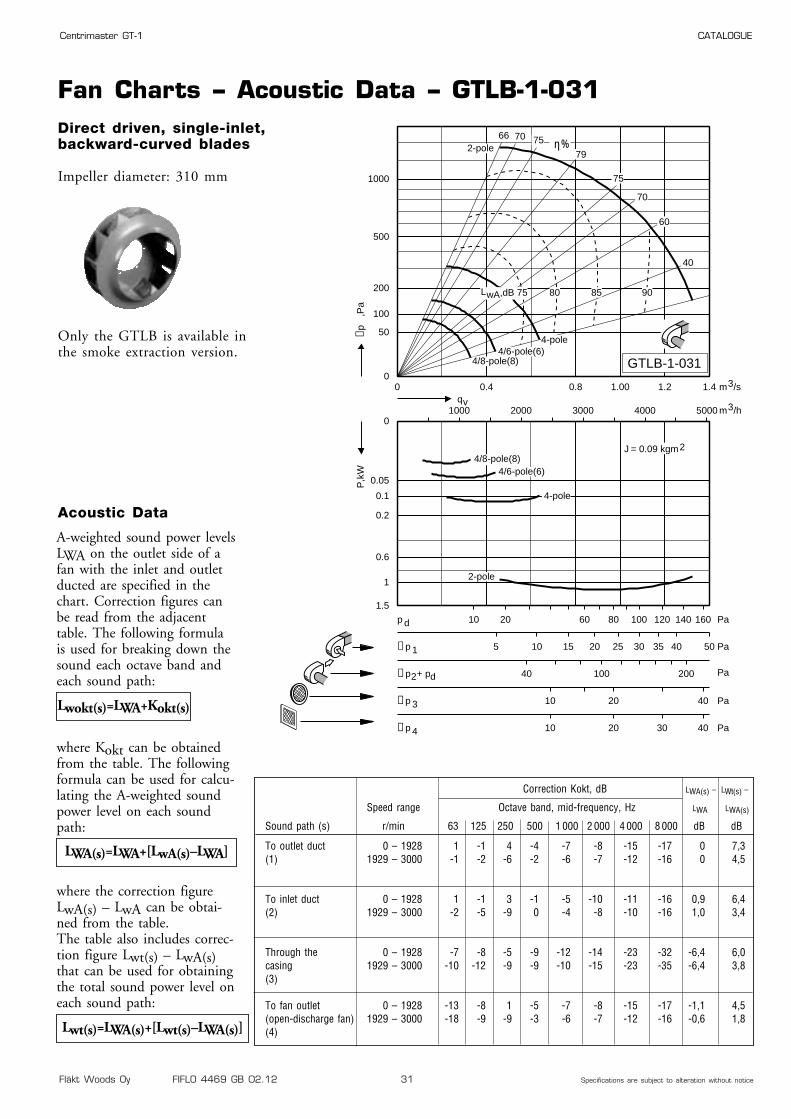
Fan Charts – Acoustic Data – GTLB-1-031Direct driven, single-inlet,backward-curved blades
Impeller diameter: 310 mm
Only the GTLB is available inthe smoke extraction version.
0 0.4 0.8 1.00 1.2 1.40
50
100
200
500
1000
0
0.05
0.1
0.2
0.6
1
1.5
1000 2000 3000 4000 5000
10 20 60 80 100 120 140 160p d Pa
40 100 200∆p2+ pd Pa
10 20 40∆p 3 Pa
5 10 15 20 25 30 35 40 50∆p 1 Pa
10 20 30 40∆p 4 Pa
40
60
70
75
79
757066 η%
4-pole
2-pole
4/6-pole(6)4/8-pole(8)
qvm3/h
m3/s
J = 0.09 kgm2
∆p,P
aP
,kW
4-pole
2-pole
4/6-pole(6)4/8-pole(8)
80 85 90,dB 75LwA
GTLB-1-031
Correction Kokt, dB LWA(s) – LWt(s) –
Speed range Octave band, mid-frequency, Hz LWA LWA(s)
Sound path (s) r/min 63 125 250 500 1 000 2 000 4 000 8 000 dB dB
To outlet duct 0 – 1928 1 -1 4 -4 -7 -8 -15 -17 0 7,3(1) 1929 – 3000 -1 -2 -6 -2 -6 -7 -12 -16 0 4,5
To inlet duct 0 – 1928 1 -1 3 -1 -5 -10 -11 -16 0,9 6,4(2) 1929 – 3000 -2 -5 -9 0 -4 -8 -10 -16 1,0 3,4
Through the 0 – 1928 -7 -8 -5 -9 -12 -14 -23 -32 -6,4 6,0casing 1929 – 3000 -10 -12 -9 -9 -10 -15 -23 -35 -6,4 3,8(3)
To fan outlet 0 – 1928 -13 -8 1 -5 -7 -8 -15 -17 -1,1 4,5(open-discharge fan) 1929 – 3000 -18 -9 -9 -3 -6 -7 -12 -16 -0,6 1,8(4)
A-weighted sound power levelsLWA on the outlet side of afan with the inlet and outletducted are specified in thechart. Correction figures canbe read from the adjacenttable. The following formulais used for breaking down thesound each octave band andeach sound path:
where Kokt can be obtainedfrom the table. The followingformula can be used for calcu-lating the A-weighted soundpower level on each soundpath:
where the correction figureLwA(s) – LwA can be obtai-ned from the table.The table also includes correc-tion figure Lwt(s) – LwA(s)that can be used for obtainingthe total sound power level oneach sound path:
Lwokt(s)=LWA+Kokt(s)
Acoustic Data
LWA(s)=LWA+[LwA(s)–LWA]
Lwt(s)=LWA(s)+[Lwt(s)–LWA(s)]

Fläkt Woods Oy FIFLO 4469 GB 02.12 32 Specifications are subject to alteration without notice
Centrimaster GT-1 CATALOGUE
Dimensions and Weights – Motor Data – GTLF-1-035
4 3 100LB APAL-4-90300-c-d 1430 24,0 HULF-1-035-c-28-06 1,5 100L APAL-6-90150-c-d 950 23,0 HULF-1-035-c-28-0
4/6 3/1 112M ATAL-4-00300-c-d 1445/975 33,0 HULF-1-035-c-28-04/8 2,8/0,6 100LB ARAL-4-90280-c-d 1430/720 23,0 HULF-1-035-c-28-0
Dimensions and Weights
Motor data
Right-hand version with 90°direction of discharge shown
Right-hand version (viewed from drive side)
Left-hand version (same dimensions as the right-hand version)
302
242272
492
483453
281
513
241,5
ø10
ø10
4,5
15
10,5
15
4,5
10,5
Outlet flange
579
261 236
ø 30
36
21
30
685
302
ø 342
453
231127
564
617
335
395
714
458
299
678 579
699
513 261
415
606
345
534
436278
90° 0° 270°
11
1)
Numberof
polesRated output
kWIECSize
Motor code Speed Weight,kg
Weight (kg) GTLF-1-035: 27,6
Hub code
Motor code: c, d: see ordering codespage 59Hub code: c = 1, right-hand version
c = 2, left-hand versionrande
Remark
1) With max. motor size
Fläkt Woods Oy FIFLO 4469 GB 02.12 33 Specifications are subject to alteration without notice
Centrimaster GT-1 CATALOGUE
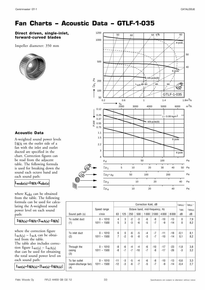
Fan Charts – Acoustic Data – GTLF-1-035Direct driven, single-inlet,forward-curved blades
Impeller diameter: 350 mm
0.2 0.6 1 1.4 1.850
100
200
500
1000
1200
0.12
0.25
0.37
0.55
0.75
1.1
1.5
2.2
3
4
2000 3000 4000 5000 6000
50 100p d Pa
50 100 200∆p2+ pd Pa
10 20 40∆p 3 Pa
5 10 20 30 40 50∆p 1 Pa
10 20 40∆p 4 Pa
40
50
60 646050
4/8-pole(8)
qvm3/h
m3/s
J = 0.08 kgm2
∆pt
,Pa
P,k
W
,dB 80 85 90
4-pole
6-pole
4/8-pole(8)
4-pole
6-pole
LwA
GTLF-1-035
η%
Correction Kokt, dB LWA(s) – LWt(s) –
Speed range Octave band, mid-frequency, Hz LWA LWA(s)
Sound path (s) r/min 63 125 250 500 1 000 2 000 4 000 8 000 dB dB
To outlet duct 0 – 1010 4 3 -2 -3 -6 -8 -10 -13 0 7,9(1) 1011 – 1500 5 3 -3 -6 -5 -7 -9 -14 0 8,2
To inlet duct 0 – 1010 6 0 -6 -5 -4 -7 -11 -18 -0,1 8,1(2) 1011 – 1500 7 -2 -9 -8 -3 -7 -10 -14 0,1 8,2
Through the 0 – 1010 -8 -6 -4 -4 -6 -10 -17 -23 -1,8 3,8casing 1011 – 1500 -8 -7 -7 -10 -7 -8 -17 -26 -3 3,2(3)
To fan outlet 0 – 1010 -11 -3 -5 -4 -6 -8 -10 -13 -0,6 3,3(open-discharge fan) 1011 – 1500 -12 -3 -6 -7 -5 -7 -9 -14 -0,4 2,7(4)
A-weighted sound power levelsLWA on the outlet side of afan with the inlet and outletducted are specified in thechart. Correction figures canbe read from the adjacenttable. The following formulais used for breaking down thesound each octave band andeach sound path:
where Kokt can be obtainedfrom the table. The followingformula can be used for calcu-lating the A-weighted soundpower level on each soundpath:
where the correction figureLwA(s) – LwA can be obtai-ned from the table.The table also includes correc-tion figure Lwt(s) – LwA(s)that can be used for obtainingthe total sound power level oneach sound path:
Lwokt(s)=LWA+Kokt(s)
Acoustic Data
LWA(s)=LWA+[LwA(s)–LWA]
Lwt(s)=LWA(s)+[Lwt(s)–LWA(s)]
Fläkt Woods Oy FIFLO 4469 GB 02.12 34 Specifications are subject to alteration without notice
Centrimaster GT-1 CATALOGUE
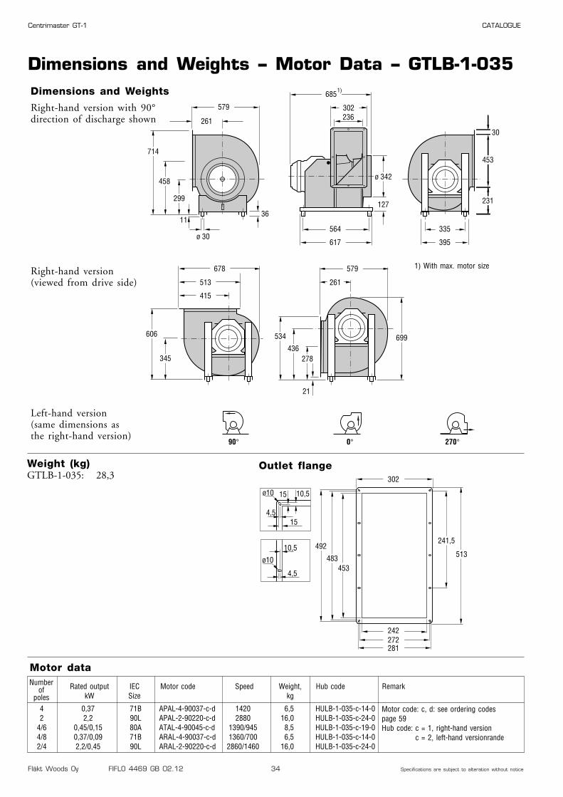
Dimensions and Weights – Motor Data – GTLB-1-035
4 0,37 71B APAL-4-90037-c-d 1420 6,5 HULB-1-035-c-14-02 2,2 90L APAL-2-90220-c-d 2880 16,0 HULB-1-035-c-24-0
4/6 0,45/0,15 80A ATAL-4-90045-c-d 1390/945 8,5 HULB-1-035-c-19-04/8 0,37/0,09 71B ARAL-4-90037-c-d 1360/700 6,5 HULB-1-035-c-14-02/4 2,2/0,45 90L ARAL-2-90220-c-d 2860/1460 16,0 HULB-1-035-c-24-0
Dimensions and Weights
Motor data
Right-hand version with 90°direction of discharge shown
Right-hand version (viewed from drive side)
Left-hand version (same dimensions as the right-hand version)
302
242272
492
483453
281
513
241,5
ø10
ø10
4,5
15
10,5
15
4,5
10,5
Outlet flange
579
261 236
ø 30
36
21
30
685
302
ø 342
453
231127
564
617
335
395
714
458
299
678 579
699
513 261
415
606
345
534
436278
90° 0° 270°
11
1)
Numberof
polesRated output
kWIECSize
Motor code Speed Weight,kg
Weight (kg) GTLB-1-035: 28,3
Hub code
Motor code: c, d: see ordering codespage 59Hub code: c = 1, right-hand version
c = 2, left-hand versionrande
Remark
1) With max. motor size
Fläkt Woods Oy FIFLO 4469 GB 02.12 35 Specifications are subject to alteration without notice
Centrimaster GT-1 CATALOGUE
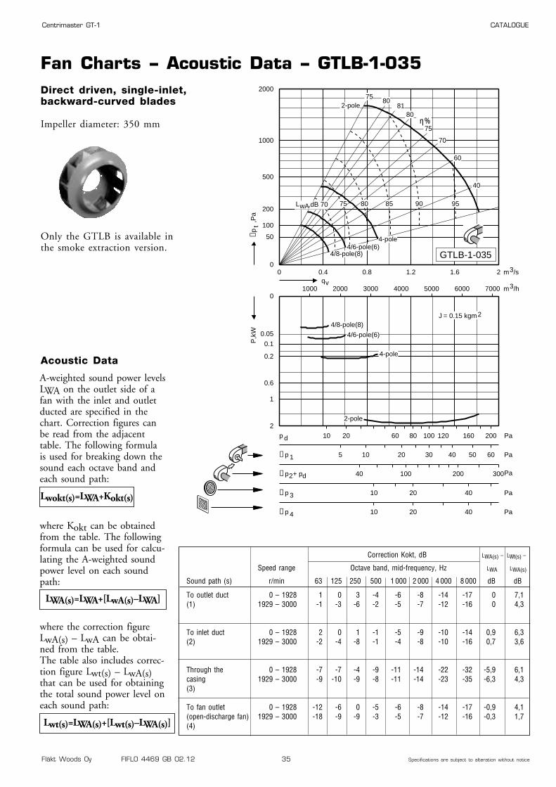
Fan Charts – Acoustic Data – GTLB-1-035Direct driven, single-inlet,backward-curved blades
Impeller diameter: 350 mm
Only the GTLB is available inthe smoke extraction version.
0 0.4 0.8 1.2 1.6 20
50
100
200
500
1000
2000
0
0.1
0.05
0.2
0.6
1
2
1000 2000 3000 4000 5000 6000 7000
10 20 60 80 100 120 160 200p d Pa
40 100 200 300∆p2+ pd Pa
10 20 40∆p 3 Pa
5 10 20 30 40 50 60∆p 1 Pa
10 20 40∆p 4 Pa
40
60
70
75
80 81
8075
η%
4-pole
2-pole
4/6-pole(6)
4/8-pole(8)
qvm3/h
m3/s
J = 0.15 kgm2
∆pt
,Pa
P,k
W
4-pole
2-pole
4/6-pole(6)4/8-pole(8)
75 80 85 90 95,dB 70LwA
GTLB-1-035
Correction Kokt, dB LWA(s) – LWt(s) –
Speed range Octave band, mid-frequency, Hz LWA LWA(s)
Sound path (s) r/min 63 125 250 500 1 000 2 000 4 000 8 000 dB dB
To outlet duct 0 – 1928 1 0 3 -4 -6 -8 -14 -17 0 7,1(1) 1929 – 3000 -1 -3 -6 -2 -5 -7 -12 -16 0 4,3
To inlet duct 0 – 1928 2 0 1 -1 -5 -9 -10 -14 0,9 6,3(2) 1929 – 3000 -2 -4 -8 -1 -4 -8 -10 -16 0,7 3,6
Through the 0 – 1928 -7 -7 -4 -9 -11 -14 -22 -32 -5,9 6,1casing 1929 – 3000 -9 -10 -9 -8 -11 -14 -23 -35 -6,3 4,3(3)
To fan outlet 0 – 1928 -12 -6 0 -5 -6 -8 -14 -17 -0,9 4,1(open-discharge fan) 1929 – 3000 -18 -9 -9 -3 -5 -7 -12 -16 -0,3 1,7(4)
A-weighted sound power levelsLWA on the outlet side of afan with the inlet and outletducted are specified in thechart. Correction figures canbe read from the adjacenttable. The following formulais used for breaking down thesound each octave band andeach sound path:
where Kokt can be obtainedfrom the table. The followingformula can be used for calcu-lating the A-weighted soundpower level on each soundpath:
where the correction figureLwA(s) – LwA can be obtai-ned from the table.The table also includes correc-tion figure Lwt(s) – LwA(s)that can be used for obtainingthe total sound power level oneach sound path:
Lwokt(s)=LWA+Kokt(s)
Acoustic Data
LWA(s)=LWA+[LwA(s)–LWA]
Lwt(s)=LWA(s)+[Lwt(s)–LWA(s)]

Fläkt Woods Oy FIFLO 4469 GB 02.12 36 Specifications are subject to alteration without notice
Centrimaster GT-1 CATALOGUE
Dimensions and Weights – Motor Data – GTLF-1-040
4 5,5 132S APAL-4-00550-c-d 1450 40,0 HULF-1-040-c-38-06 2,2 112M APAL-6-00220-c-d 940 27,0 HULF-1-040-c-28-08 1,1 100LB APAL-8-90110-c-d 700 23,0 HULF-1-040-c-28-0
4/6 6/2 132M ATAL-4-00600-c-d 1460/980 59,0 HULF-1-040-c-38-04/8 5,0/1,0 132S ARAL-4-00500-c-d 1450/725 48,0 HULF-1-040-c-38-0
Dimensions and Weights
Motor data
Right-hand version with 90°direction of discharge shown
Right-hand version (viewed from drive side)
Left-hand version (same dimensions as the right-hand version)
329
269299
546
537507
308
4 x134,3
-149,5ø10
ø10
15
15
15
19,5
4,5
19,5
567
Outlet flange
648
290 263
ø 30
36
25
30
750
329
ø 388
507
256134
589
639
355
415
793
510
329
759 648
784
567 290
464
678
386
593
489310
90° 0° 270°
11
1)
Numberof
polesRated output
kWIECSize
Motor code Speed Weight,kg
Weight (kg) GTLF-1-040: 32,5
Hub code
Motor code: c, d: see ordering codespage 59Hub code: c = 1, right-hand version
c = 2, left-hand versionrande
Remark
1) With max. motor size
Fläkt Woods Oy FIFLO 4469 GB 02.12 37 Specifications are subject to alteration without notice
Centrimaster GT-1 CATALOGUE
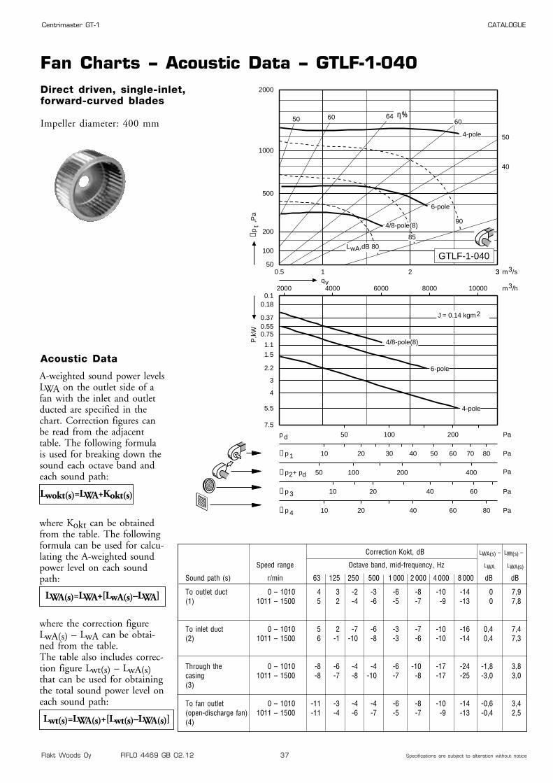
Fan Charts – Acoustic Data – GTLF-1-040Direct driven, single-inlet,forward-curved blades
Impeller diameter: 400 mm
0.5 1 2 350
100
200
500
1000
2000
40
50
60646050
0.10.18
0.370.550.75
1.1
1.5
2.2
3
4
5.5
7.5
2000 4000 6000 8000 10000
50 100 200p d Pa
50 100 200 400∆p2+ pd Pa
10 20 40 60∆p 3 Pa
10 20 30 40 50 60 70 80∆p 1 Pa
10 20 40 60 80∆p 4 Pa
∆pt
,Pa
P,k
W
qv
3
m3/h
m3/s
J = 0.14 kgm2
90
85,dB 80LwA
4-pole
6-pole
4/8-pole(8)
4-pole
6-pole
4/8-pole(8)
GTLF-1-040
η%
Correction Kokt, dB LWA(s) – LWt(s) –
Speed range Octave band, mid-frequency, Hz LWA LWA(s)
Sound path (s) r/min 63 125 250 500 1 000 2 000 4 000 8 000 dB dB
To outlet duct 0 – 1010 4 3 -2 -3 -6 -8 -10 -14 0 7,9(1) 1011 – 1500 5 2 -4 -6 -5 -7 -9 -13 0 7,8
To inlet duct 0 – 1010 5 2 -7 -6 -3 -7 -10 -16 0,4 7,4(2) 1011 – 1500 6 -1 -10 -8 -3 -6 -10 -14 0,4 7,3
Through the 0 – 1010 -8 -6 -4 -4 -6 -10 -17 -24 -1,8 3,8casing 1011 – 1500 -8 -7 -8 -10 -7 -8 -17 -25 -3,0 3,0(3)
To fan outlet 0 – 1010 -11 -3 -4 -4 -6 -8 -10 -14 -0,6 3,4(open-discharge fan) 1011 – 1500 -11 -4 -6 -7 -5 -7 -9 -13 -0,4 2,5(4)
A-weighted sound power levelsLWA on the outlet side of afan with the inlet and outletducted are specified in thechart. Correction figures canbe read from the adjacenttable. The following formulais used for breaking down thesound each octave band andeach sound path:
where Kokt can be obtainedfrom the table. The followingformula can be used for calcu-lating the A-weighted soundpower level on each soundpath:
where the correction figureLwA(s) – LwA can be obtai-ned from the table.The table also includes correc-tion figure Lwt(s) – LwA(s)that can be used for obtainingthe total sound power level oneach sound path:
Lwokt(s)=LWA+Kokt(s)
Acoustic Data
LWA(s)=LWA+[LwA(s)–LWA]
Lwt(s)=LWA(s)+[Lwt(s)–LWA(s)]

Fläkt Woods Oy FIFLO 4469 GB 02.12 38 Specifications are subject to alteration without notice
Centrimaster GT-1 CATALOGUE
Dimensions and Weights – Motor Data – GTLB-1-040
4 0,55 80A APAL-4-90055-c-d 1350 9,0 HULB-1-040-c-19-02 4 112M APAL-2-00400-c-d 2850 25,0 HULB-1-040-c-28-0
4/6 0,75/0,22 80B ATAL-4-90075-c-d 1400/955 10,5 HULB-1-040-c-19-04/8 0,55/0,11 80A ARAL-4-90055-c-d 1410/690 8,5 HULB-1-040-c-19-02/4 4,5/1 112M ARAL-2-00450-c-d 2875/1450 32,0 HULB-1-040-c-28-0
Dimensions and Weights
Motor data
Right-hand version with 90°direction of discharge shown
Right-hand version (viewed from drive side)
Left-hand version (same dimensions as the right-hand version)
329
269299
546
537507
308
4 x134,3
-149,5ø10
ø10
15
15
15
19,5
4,5
19,5
567
Outlet flange
648
290 263
ø 30
36
25
30
750
329
ø 388
507
256134
589
639
355
415
793
510
329
759 648
784
567 290
464
678
386
593
489310
90° 0° 270°
11
1)
Numberof
polesRated output
kWIECSize
Motor code Speed Weight,kg
Weight (kg) GTLB-1-040: 34,2
Hub code
Motor code: c, d: see ordering codespage 59Hub code: c = 1, right-hand version
c = 2, left-hand versionrande
Remark
1) With max. motor size
Fläkt Woods Oy FIFLO 4469 GB 02.12 39 Specifications are subject to alteration without notice
Centrimaster GT-1 CATALOGUE
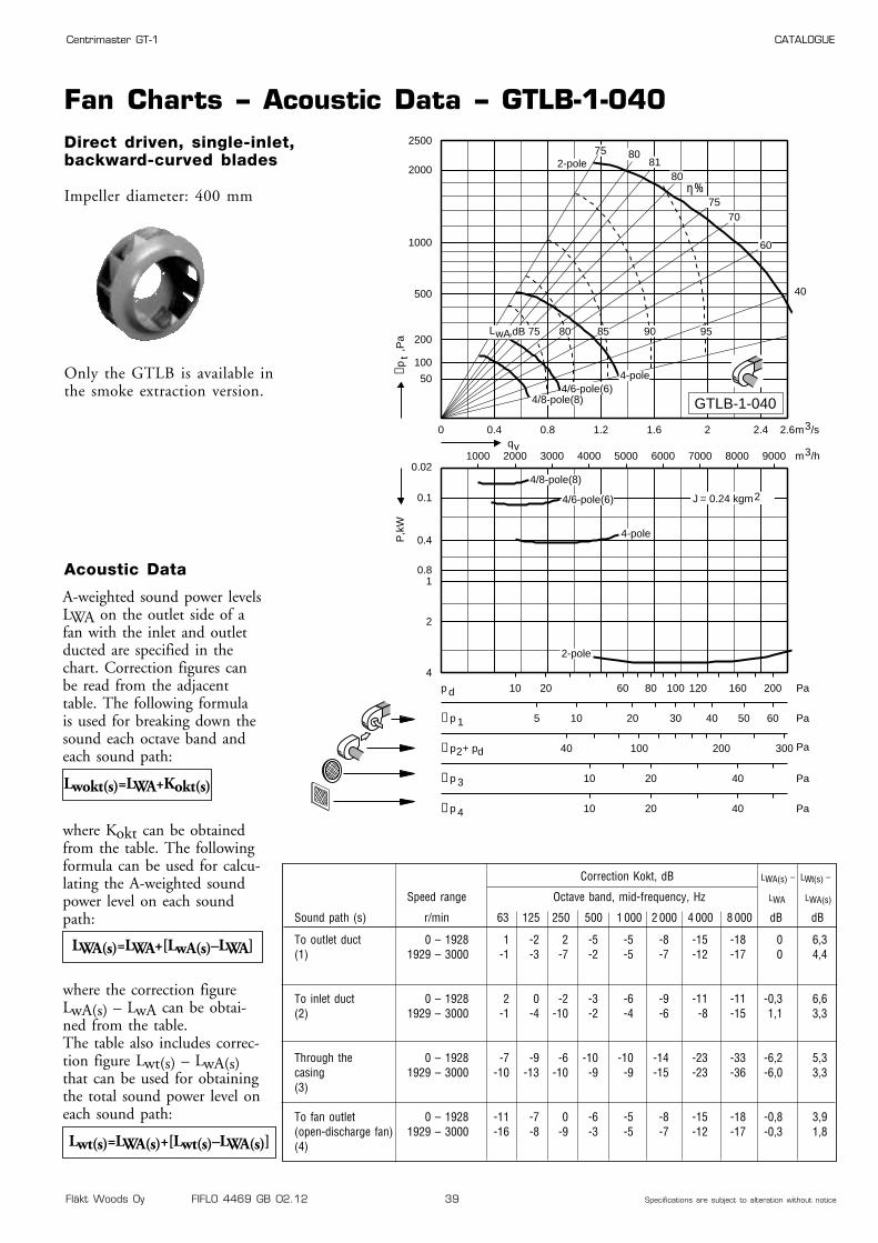
Fan Charts – Acoustic Data – GTLB-1-040Direct driven, single-inlet,backward-curved blades
Impeller diameter: 400 mm
Only the GTLB is available inthe smoke extraction version.
0 0.4 0.8 1.2 1.6 2 2.4 2.6
50
100
200
500
1000
2000
2500
0.02
0.1
0.4
0.81
2
4
1000 2000 3000 4000 5000 6000 7000 8000 9000
10 20 60 80 100 120 160 200p d Pa
40 100 200 300∆p2+ pd Pa
10 20 40∆p 3 Pa
5 10 20 30 40 50 60∆p 1 Pa
10 20 40∆p 4 Pa
40
60
7075
80 81
8075
η%
4-pole
2-pole
4/6-pole(6)
4/8-pole(8)
qvm3/h
m3/s
J = 0.24 kgm2
∆pt
,Pa
P,k
W
4-pole
2-pole
4/6-pole(6)4/8-pole(8)
,dB 75 80 85 90 95LwA
GTLB-1-040
Correction Kokt, dB LWA(s) – LWt(s) –
Speed range Octave band, mid-frequency, Hz LWA LWA(s)
Sound path (s) r/min 63 125 250 500 1 000 2 000 4 000 8 000 dB dB
To outlet duct 0 – 1928 1 -2 2 -5 -5 -8 -15 -18 0 6,3(1) 1929 – 3000 -1 -3 -7 -2 -5 -7 -12 -17 0 4,4
To inlet duct 0 – 1928 2 0 -2 -3 -6 -9 -11 -11 -0,3 6,6(2) 1929 – 3000 -1 -4 -10 -2 -4 -6 -8 -15 1,1 3,3
Through the 0 – 1928 -7 -9 -6 -10 -10 -14 -23 -33 -6,2 5,3casing 1929 – 3000 -10 -13 -10 -9 -9 -15 -23 -36 -6,0 3,3(3)
To fan outlet 0 – 1928 -11 -7 0 -6 -5 -8 -15 -18 -0,8 3,9(open-discharge fan) 1929 – 3000 -16 -8 -9 -3 -5 -7 -12 -17 -0,3 1,8(4)
A-weighted sound power levelsLWA on the outlet side of afan with the inlet and outletducted are specified in thechart. Correction figures canbe read from the adjacenttable. The following formulais used for breaking down thesound each octave band andeach sound path:
where Kokt can be obtainedfrom the table. The followingformula can be used for calcu-lating the A-weighted soundpower level on each soundpath:
where the correction figureLwA(s) – LwA can be obtai-ned from the table.The table also includes correc-tion figure Lwt(s) – LwA(s)that can be used for obtainingthe total sound power level oneach sound path:
Lwokt(s)=LWA+Kokt(s)
Acoustic Data
LWA(s)=LWA+[LwA(s)–LWA]
Lwt(s)=LWA(s)+[Lwt(s)–LWA(s)]

Fläkt Woods Oy FIFLO 4469 GB 02.12 40 Specifications are subject to alteration without notice
Centrimaster GT-1 CATALOGUE
Dimensions and Weights – Motor Data – GTLF-1-045
6 4 132MA APAL-6-00400-c-d 955 46,0 HULF-1-045-c-38-08 1,5 112M APAL-8-00150-c-d 695 4,5 HULF-1-045-c-28-0
Dimensions and Weights
Motor data
Right-hand version with 90°direction of discharge shown
Right-hand version (viewed from drive side)
Left-hand version (same dimensions as the right-hand version)
359
299329
608
599569
338
629
4 x149,8
-
ø10
ø10
15
15164,5
15
19,5
4,5
19,5
Outlet flange
725
322 293
ø 30
36
26
30
777
359
ø 445
569
279139
615
665
370
430
878
563
361
851 725
876
632 322
517
786
464
655
543341
90° 0° 270°
11
1)
Numberof
polesRated output
kWIECSize
Motor code Speed Weight,kg
Weight (kg) GTLF-1-045: 38,3
Hub code
Motor code: c, d: see ordering codespage 59Hub code: c = 1, right-hand version
c = 2, left-hand versionrande
Remark
1) With max. motor size
Fläkt Woods Oy FIFLO 4469 GB 02.12 41 Specifications are subject to alteration without notice
Centrimaster GT-1 CATALOGUE
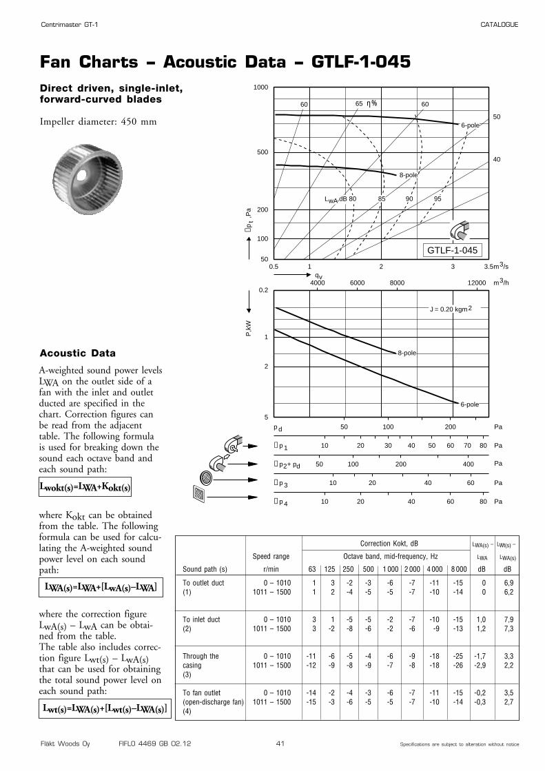
Fan Charts – Acoustic Data – GTLF-1-045Direct driven, single-inlet,forward-curved blades
Impeller diameter: 450 mm
0.5 1 2 3 3.550
100
200
500
1000
0.2
1
2
5
4000 6000 8000 12000
50 100 200p d Pa
50 100 200 400∆p2+ pd Pa
10 20 40 60∆p 3 Pa
10 20 30 40 50 60 70 80∆p 1 Pa
10 20 40 60 80∆p 4 Pa
40
50
606560
6-pole
8-pole
qvm3/h
m3/s
J = 0.20 kgm2
∆pt
,Pa
P,k
W
,dB 80 85 90 95LwA
8-pole
6-pole
GTLF-1-045
η%
Correction Kokt, dB LWA(s) – LWt(s) –
Speed range Octave band, mid-frequency, Hz LWA LWA(s)
Sound path (s) r/min 63 125 250 500 1 000 2 000 4 000 8 000 dB dB
To outlet duct 0 – 1010 1 3 -2 -3 -6 -7 -11 -15 0 6,9(1) 1011 – 1500 1 2 -4 -5 -5 -7 -10 -14 0 6,2
To inlet duct 0 – 1010 3 1 -5 -5 -2 -7 -10 -15 1,0 7,9(2) 1011 – 1500 3 -2 -8 -6 -2 -6 -9 -13 1,2 7,3
Through the 0 – 1010 -11 -6 -5 -4 -6 -9 -18 -25 -1,7 3,3casing 1011 – 1500 -12 -9 -8 -9 -7 -8 -18 -26 -2,9 2,2(3)
To fan outlet 0 – 1010 -14 -2 -4 -3 -6 -7 -11 -15 -0,2 3,5(open-discharge fan) 1011 – 1500 -15 -3 -6 -5 -5 -7 -10 -14 -0,3 2,7(4)
A-weighted sound power levelsLWA on the outlet side of afan with the inlet and outletducted are specified in thechart. Correction figures canbe read from the adjacenttable. The following formulais used for breaking down thesound each octave band andeach sound path:
where Kokt can be obtainedfrom the table. The followingformula can be used for calcu-lating the A-weighted soundpower level on each soundpath:
where the correction figureLwA(s) – LwA can be obtai-ned from the table.The table also includes correc-tion figure Lwt(s) – LwA(s)that can be used for obtainingthe total sound power level oneach sound path:
Lwokt(s)=LWA+Kokt(s)
Acoustic Data
LWA(s)=LWA+[LwA(s)–LWA]
Lwt(s)=LWA(s)+[Lwt(s)–LWA(s)]

Fläkt Woods Oy FIFLO 4469 GB 02.12 42 Specifications are subject to alteration without notice
Centrimaster GT-1 CATALOGUE
Dimensions and Weights – Motor Data – GTLB-1-045
4 1,1 90S APAL-4-90110-c-d 1410 13,0 HULB-1-045-c-24-06 0,37 80A APAL-6-90037-c-d 915 9,0 HULB-1-045-c-19-0
4/6 1/0,3 90S ATAL-4-90100-c-d 1400/940 13,0 HULB-1-045-c-24-04/8 1,1/0,26 90S ARAL-4-90110-c-d 1410/700 13,0 HULB-1-045-c-24-0
Dimensions and Weights
Motor data
Right-hand version with 90°direction of discharge shown
Right-hand version (viewed from drive side)
Left-hand version (same dimensions as the right-hand version)
359
299329
608
599569
338
629
4 x149,8
-
ø10
ø10
15
15164,5
15
19,5
4,5
19,5
Outlet flange
725
322 293
ø 30
36
26
30
777
359
ø 445
569
279139
615
665
370
430
878
563
361
851 725
876
632 322
517
786
464
655
543341
90° 0° 270°
11
1)
Numberof
polesRated output
kWIECSize
Motor code Speed Weight,kg
Weight (kg) GTLB-1-045: 41,2
Hub code
Motor code: c, d: see ordering codespage 59Hub code: c = 1, right-hand version
c = 2, left-hand versionrande
Remark
1) With max. motor size
Fläkt Woods Oy FIFLO 4469 GB 02.12 43 Specifications are subject to alteration without notice
Centrimaster GT-1 CATALOGUE
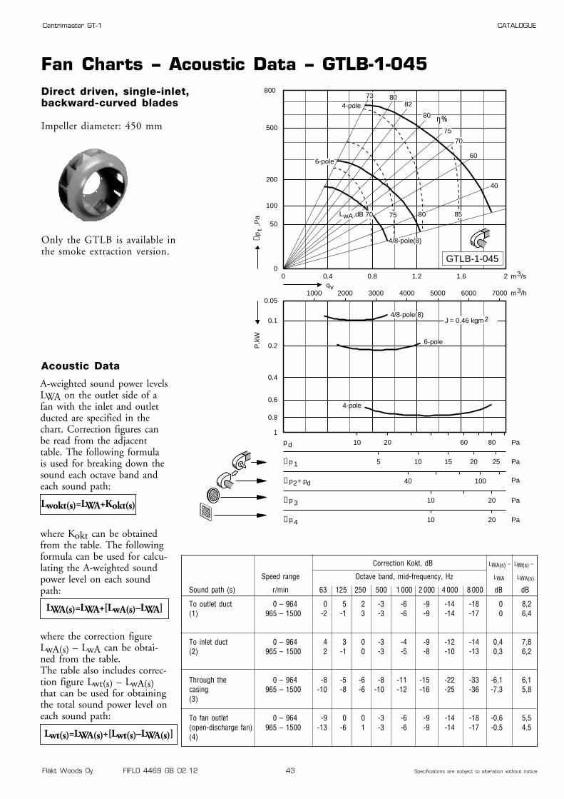
Fan Charts – Acoustic Data – GTLB-1-045Direct driven, single-inlet,backward-curved blades
Impeller diameter: 450 mm
Only the GTLB is available inthe smoke extraction version.
0 0.4 0.8 1.2 1.6 20
50
100
200
500
800
0.05
0.1
0.2
0.4
0.6
0.8
1
1000 2000 3000 4000 5000 6000 7000
10 20 60 80p d Pa
40 100∆p2+ pd Pa
10 20∆p 3 Pa
5 10 15 20 25∆p 1 Pa
10 20∆p 4 Pa
40
60
70
75
80
828073
η%
4-pole
6-pole
4/8-pole(8)
qvm3/h
m3/s
J = 0.46 kgm2
∆pt
,Pa
P,k
W
4-pole
6-pole
4/8-pole(8)
,dB 70 75 80 85LwA
GTLB-1-045
Correction Kokt, dB LWA(s) – LWt(s) –
Speed range Octave band, mid-frequency, Hz LWA LWA(s)
Sound path (s) r/min 63 125 250 500 1 000 2 000 4 000 8 000 dB dB
To outlet duct 0 – 964 0 5 2 -3 -6 -9 -14 -18 0 8,2(1) 965 – 1500 -2 -1 3 -3 -6 -9 -14 -17 0 6,4
To inlet duct 0 – 964 4 3 0 -3 -4 -9 -12 -14 0,4 7,8(2) 965 – 1500 2 -1 0 -3 -5 -8 -10 -13 0,3 6,2
Through the 0 – 964 -8 -5 -6 -8 -11 -15 -22 -33 -6,1 6,1casing 965 – 1500 -10 -8 -6 -10 -12 -16 -25 -36 -7,3 5,8(3)
To fan outlet 0 – 964 -9 0 0 -3 -6 -9 -14 -18 -0,6 5,5(open-discharge fan) 965 – 1500 -13 -6 1 -3 -6 -9 -14 -17 -0,5 4,5(4)
A-weighted sound power levelsLWA on the outlet side of afan with the inlet and outletducted are specified in thechart. Correction figures canbe read from the adjacenttable. The following formulais used for breaking down thesound each octave band andeach sound path:
where Kokt can be obtainedfrom the table. The followingformula can be used for calcu-lating the A-weighted soundpower level on each soundpath:
where the correction figureLwA(s) – LwA can be obtai-ned from the table.The table also includes correc-tion figure Lwt(s) – LwA(s)that can be used for obtainingthe total sound power level oneach sound path:
Lwokt(s)=LWA+Kokt(s)
Acoustic Data
LWA(s)=LWA+[LwA(s)–LWA]
Lwt(s)=LWA(s)+[Lwt(s)–LWA(s)]
Fläkt Woods Oy FIFLO 4469 GB 02.12 44 Specifications are subject to alteration without notice
Centrimaster GT-1 CATALOGUE
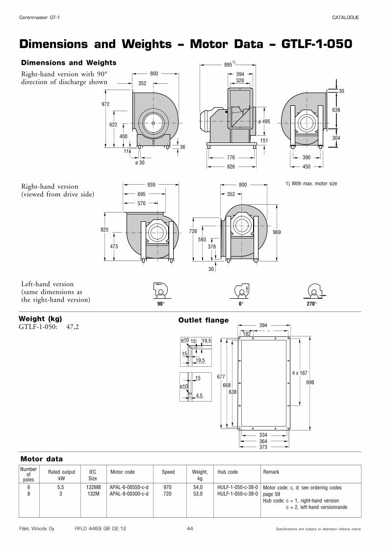
Dimensions and Weights – Motor Data – GTLF-1-050
6 5,5 132MB APAL-6-00550-c-d 970 54,0 HULF-1-050-c-38-08 3 132M APAL-8-00300-c-d 720 53,0 HULF-1-050-c-38-0
Dimensions and Weights
Motor data
Right-hand version with 90°direction of discharge shown
Right-hand version (viewed from drive side)
Left-hand version (same dimensions as the right-hand version)
394
334364
677
668638
373
698
4 x 167
-182
ø10
ø10
15
15
15
19,5
4,5
19,5
Outlet flange
800
352 328
ø 30
36
30
30
895
394
ø 495
638
304151
776
826
390
450
972
622
400
939 800
969
695 352
570
825
473
726
593378
90° 0° 270°
11
1)
Numberof
polesRated output
kWIECSize
Motor code Speed Weight,kg
Weight (kg) GTLF-1-050: 47,2
Hub code
Motor code: c, d: see ordering codespage 59Hub code: c = 1, right-hand version
c = 2, left-hand versionrande
Remark
1) With max. motor size
Fläkt Woods Oy FIFLO 4469 GB 02.12 45 Specifications are subject to alteration without notice
Centrimaster GT-1 CATALOGUE
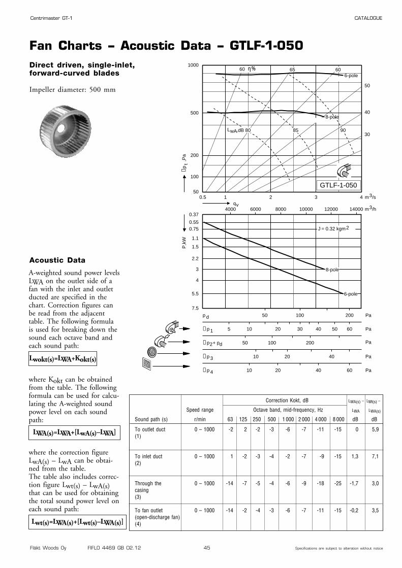
Fan Charts – Acoustic Data – GTLF-1-050Direct driven, single-inlet,forward-curved blades
Impeller diameter: 500 mm
0.5 1 2 3 450
100
200
500
1000
0.37
0.550.75
1.1
1.5
2.2
3
4
5.5
7.5
4000 6000 8000 10000 12000 14000
50 100 200p d Pa
50 100 200∆p2+ pd Pa
10 20 40∆p 3 Pa
5 10 20 30 40 50 60∆p 1 Pa
10 20 40 60∆p 4 Pa
30
40
50
606560
qvm3/h
m3/s
J = 0.32 kgm2
∆pt
,Pa
P,k
W
85 90
6-pole
8-pole
,dB 80LwA
6-pole
8-pole
GTLF-1-050
η%
Correction Kokt, dB LWA(s) – LWt(s) –
Speed range Octave band, mid-frequency, Hz LWA LWA(s)
Sound path (s) r/min 63 125 250 500 1 000 2 000 4 000 8 000 dB dB
To outlet duct 0 – 1000 -2 2 -2 -3 -6 -7 -11 -15 0 5,9(1)
To inlet duct 0 – 1000 1 -2 -3 -4 -2 -7 -9 -15 1,3 7,1(2)
Through the 0 – 1000 -14 -7 -5 -4 -6 -9 -18 -25 -1,7 3,0casing (3)
To fan outlet 0 – 1000 -14 -2 -4 -3 -6 -7 -11 -15 -0,2 3,5(open-discharge fan)(4)
A-weighted sound power levelsLWA on the outlet side of afan with the inlet and outletducted are specified in thechart. Correction figures canbe read from the adjacenttable. The following formulais used for breaking down thesound each octave band andeach sound path:
where Kokt can be obtainedfrom the table. The followingformula can be used for calcu-lating the A-weighted soundpower level on each soundpath:
where the correction figureLwA(s) – LwA can be obtai-ned from the table.The table also includes correc-tion figure Lwt(s) – LwA(s)that can be used for obtainingthe total sound power level oneach sound path:
Lwokt(s)=LWA+Kokt(s)
Acoustic Data
LWA(s)=LWA+[LwA(s)–LWA]
Lwt(s)=LWA(s)+[Lwt(s)–LWA(s)]

Fläkt Woods Oy FIFLO 4469 GB 02.12 46 Specifications are subject to alteration without notice
Centrimaster GT-1 CATALOGUE
Dimensions and Weights – Motor Data – GTLB-1-050
4 1,5 90L APAL-4-90150-c-d 1420 16,0 HULB-1-050-c-24-06 0,55 80B APAL-6-90055-c-d 900 10,0 HULB-1-050-c-19-0
4/6 1,5/0,45 90L ATAL-4-90150-c-d 1400/930 16,0 HULB-1-050-c-24-04/8 1,7/0,35 90L ARAL-4-90170-c-d 1390/700 16,0 HULB-1-050-c-24-0
Dimensions and Weights
Motor data
Right-hand version with 90°direction of discharge shown
Right-hand version (viewed from drive side)
Left-hand version (same dimensions as the right-hand version)
394
334364
677
668638
373
698
4 x 167
-182
ø10
ø10
15
15
15
19,5
4,5
19,5
Outlet flange
800
352 328
ø 30
36
30
30
895
394
ø 495
638
304151
776
826
390
450
972
622
400
939 800
969
695 352
570
825
473
726
593378
90° 0° 270°
11
1)
Numberof
polesRated output
kWIECSize
Motor code Speed Weight,kg
Weight (kg) GTLB-1-050: 50,7
Hub code
Motor code: c, d: see ordering codespage 59Hub code: c = 1, right-hand version
c = 2, left-hand versionrande
Remark
1) With max. motor size
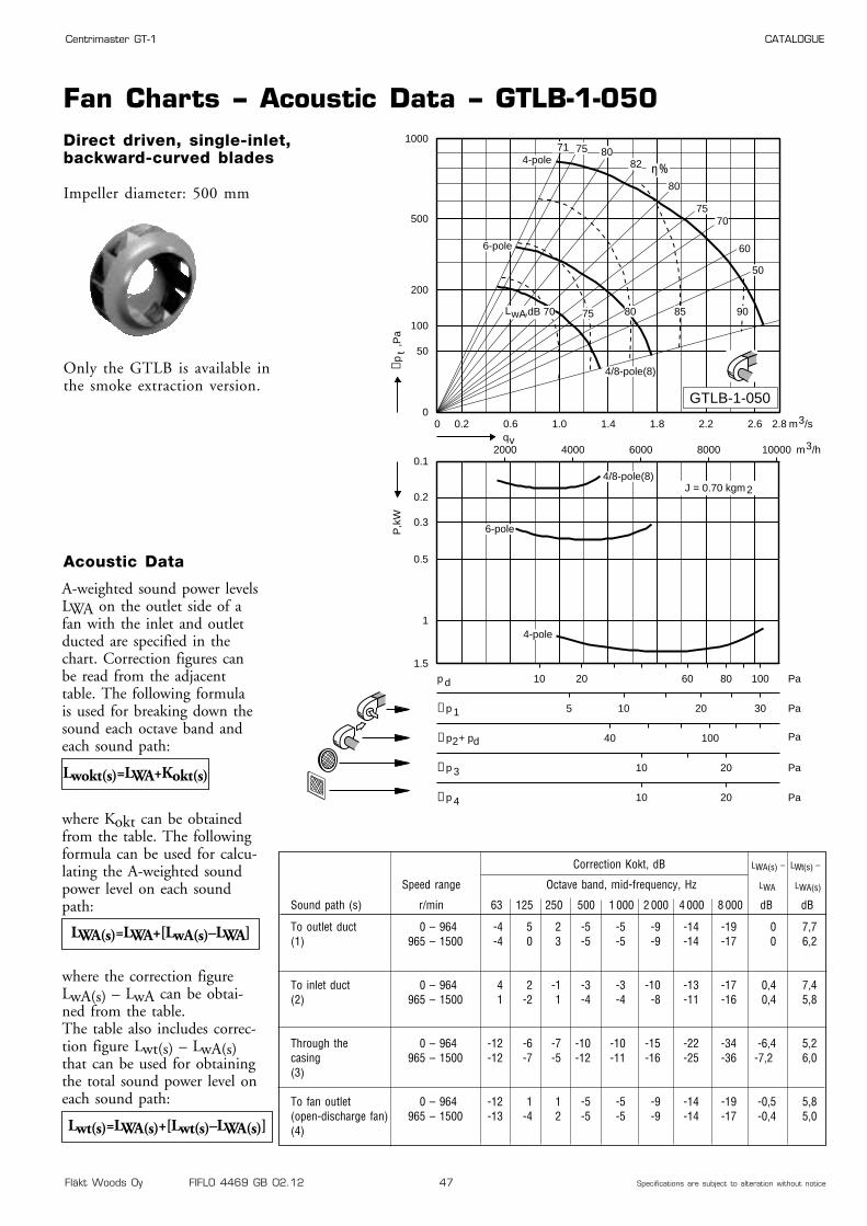
Fläkt Woods Oy FIFLO 4469 GB 02.12 47 Specifications are subject to alteration without notice
Centrimaster GT-1 CATALOGUE
Fan Charts – Acoustic Data – GTLB-1-050Direct driven, single-inlet,backward-curved blades
Impeller diameter: 500 mm
Only the GTLB is available inthe smoke extraction version.
0 0.2 0.6 1.0 1.4 1.8 2.2 2.6 2.80
50
100
200
500
1000
0.1
0.2
0.3
0.5
1
1.5
2000 4000 6000 8000 10000
10 20 60 80 100p d Pa
40 100∆p2+ pd Pa
10 20∆p 3 Pa
5 10 20 30∆p 1 Pa
10 20∆p 4 Pa
50
60
7075
80
82807571
η%
4-pole
6-pole
4/8-pole(8)
qvm3/h
m3/s
= 0.70 kgm2
∆pt
,Pa
P,k
W
4-pole
6-pole
4/8-pole(8)
,dB 70 75 80 85 90LwA
J
GTLB-1-050
Correction Kokt, dB LWA(s) – LWt(s) –
Speed range Octave band, mid-frequency, Hz LWA LWA(s)
Sound path (s) r/min 63 125 250 500 1 000 2 000 4 000 8 000 dB dB
To outlet duct 0 – 964 -4 5 2 -5 -5 -9 -14 -19 0 7,7(1) 965 – 1500 -4 0 3 -5 -5 -9 -14 -17 0 6,2
To inlet duct 0 – 964 4 2 -1 -3 -3 -10 -13 -17 0,4 7,4(2) 965 – 1500 1 -2 1 -4 -4 -8 -11 -16 0,4 5,8
Through the 0 – 964 -12 -6 -7 -10 -10 -15 -22 -34 -6,4 5,2casing 965 – 1500 -12 -7 -5 -12 -11 -16 -25 -36 -7,2 6,0(3)
To fan outlet 0 – 964 -12 1 1 -5 -5 -9 -14 -19 -0,5 5,8(open-discharge fan) 965 – 1500 -13 -4 2 -5 -5 -9 -14 -17 -0,4 5,0(4)
A-weighted sound power levelsLWA on the outlet side of afan with the inlet and outletducted are specified in thechart. Correction figures canbe read from the adjacenttable. The following formulais used for breaking down thesound each octave band andeach sound path:
where Kokt can be obtainedfrom the table. The followingformula can be used for calcu-lating the A-weighted soundpower level on each soundpath:
where the correction figureLwA(s) – LwA can be obtai-ned from the table.The table also includes correc-tion figure Lwt(s) – LwA(s)that can be used for obtainingthe total sound power level oneach sound path:
Lwokt(s)=LWA+Kokt(s)
Acoustic Data
LWA(s)=LWA+[LwA(s)–LWA]
Lwt(s)=LWA(s)+[Lwt(s)–LWA(s)]
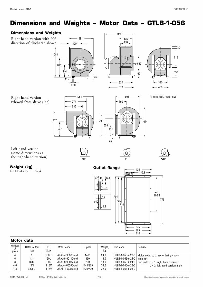
Fläkt Woods Oy FIFLO 4469 GB 02.12 48 Specifications are subject to alteration without notice
Centrimaster GT-1 CATALOGUE
Dimensions and Weights – Motor Data – GTLB-1-056
4 3 100LB APAL-4-90300-c-d 1430 24,0 HULB-1-056-c-28-06 1,1 90L APAL-6-90110-c-d 930 16,0 HULB-1-056-c-24-08 0,37 90S APAL-8-90037-c-d 700 13,0 HULB-1-056-c-24-0
4/6 3/1 112M ATAL-4-00300-c-d 1445/975 33,0 HULB-1-056-c-28-04/8 3,5/0,7 112M ARAL-4-00350-c-d 1430/720 32,0 HULB-1-056-c-28-0
Dimensions and Weights
Motor data
Right-hand version with 90°direction of discharge shown
Right-hand version (viewed from drive side)
Left-hand version (same dimensions as the right-hand version)
435
375405
754
745715
414
775
4 x186,3
186,3109,3
ø10
ø10
15
15
15
19,5
4,5
19,5
Outlet flange
891
390 368
ø 30
36
25
30
975
435
ø 562
715
336162
820
870
390
450
1081
693
444
1051 891
1074
774 390
636
917
527
799
659411
90° 0° 270°
11
1)
Numberof
polesRated output
kWIECSize
Motor code Speed Weight,kg
Weight (kg) GTLB-1-056: 67,4
Hub code
Motor code: c, d: see ordering codespage 59Hub code: c = 1, right-hand version
c = 2, left-hand versionrande
Remark
1) With max. motor size
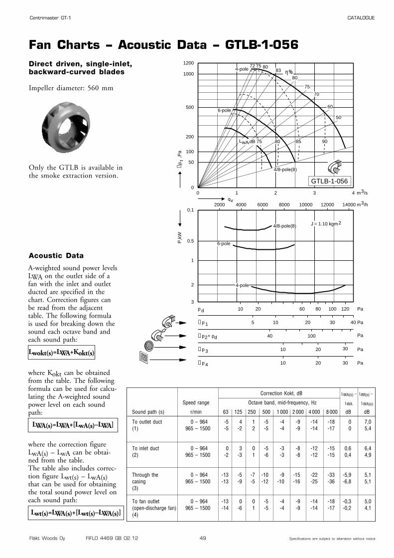
Fläkt Woods Oy FIFLO 4469 GB 02.12 49 Specifications are subject to alteration without notice
Centrimaster GT-1 CATALOGUE
Fan Charts – Acoustic Data – GTLB-1-056Direct driven, single-inlet,backward-curved blades
Impeller diameter: 560 mm
Only the GTLB is available inthe smoke extraction version.
0 1 2 3 40
50
100
200
500
1000
1200
0.1
0.5
1
2
3
2000 4000 6000 8000 10000 12000 14000
10 20 60 80 100 120p d Pa
40 100∆p2+ pd Pa
10 20∆p 3 Pa
5 10 20 30 40∆p 1 Pa
10 20 30
30
∆p 4 Pa
50
60
70
75
80
83807572
η%
4-pole
6-pole
4/8-pole(8)
qvm3/h
m3/s
J = 1.10 kgm2
∆pt
,Pa
P,k
W
4-pole
6-pole
4/8-pole(8)
8580 90,dB 75LwA
GTLB-1-056
Correction Kokt, dB LWA(s) – LWt(s) –
Speed range Octave band, mid-frequency, Hz LWA LWA(s)
Sound path (s) r/min 63 125 250 500 1 000 2 000 4 000 8 000 dB dB
To outlet duct 0 – 964 -5 4 1 -5 -4 -9 -14 -18 0 7,0(1) 965 – 1500 -5 -2 2 -5 -4 -9 -14 -17 0 5,4
To inlet duct 0 – 964 0 3 0 -5 -3 -8 -12 -15 0,6 6,4(2) 965 – 1500 -2 -3 1 -6 -3 -8 -12 -15 0,4 4,9
Through the 0 – 964 -13 -5 -7 -10 -9 -15 -22 -33 -5,9 5,1casing 965 – 1500 -13 -9 -5 -12 -10 -16 -25 -36 -6,8 5,1(3)
To fan outlet 0 – 964 -13 0 0 -5 -4 -9 -14 -18 -0,3 5,0(open-discharge fan) 965 – 1500 -14 -6 1 -5 -4 -9 -14 -17 -0,2 4,1(4)
A-weighted sound power levelsLWA on the outlet side of afan with the inlet and outletducted are specified in thechart. Correction figures canbe read from the adjacenttable. The following formulais used for breaking down thesound each octave band andeach sound path:
where Kokt can be obtainedfrom the table. The followingformula can be used for calcu-lating the A-weighted soundpower level on each soundpath:
where the correction figureLwA(s) – LwA can be obtai-ned from the table.The table also includes correc-tion figure Lwt(s) – LwA(s)that can be used for obtainingthe total sound power level oneach sound path:
Lwokt(s)=LWA+Kokt(s)
Acoustic Data
LWA(s)=LWA+[LwA(s)–LWA]
Lwt(s)=LWA(s)+[Lwt(s)–LWA(s)]

Fläkt Woods Oy FIFLO 4469 GB 02.12 50 Specifications are subject to alteration without notice
Centrimaster GT-1 CATALOGUE
Dimensions and Weights – Motor Data – GTLB-1-063
4 5,5 132S APAL-4-00550-c-d 1450 40,0 HULB-1-063-c-38-06 2,2 112M APAL-6-00220-c-d 940 27,0 HULB-1-063-c-28-08 0,75 100LA APAL-8-90075-c-d 700 20,0 HULB-1-063-c-28-0
4/6 6/2 132M ATAL-4-00600-c-d 1460/980 59,0 HULB-1-063-c-38-04/8 6,8/1,4 132M ARAL-4-00680-c-d 1460/730 59,0 HULB-1-063-c-38-0
Dimensions and Weights
Motor data
Right-hand version with 90°direction of discharge shown
Right-hand version (viewed from drive side)
Left-hand version (same dimensions as the right-hand version)
477
417447
840
831801
456
861
4 x207,8
207,8119,6
ø10
ø10
15
15
15
19,5
4,5
19,5
Outlet flange
998
434 409
ø 30
36
21
30
1018
477
ø 620
801
345182
864
914
447
508
1204
774
493
1174 998
1198
859 434
711
1028
596
880
732452
90° 0° 270°
11
1)
Numberof
polesRated output
kWIECSize
Motor code Speed Weight,kg
Weight (kg) GTLB-1-063: 91,9
Hub code
Motor code: c, d: see ordering codespage 59Hub code: c = 1, right-hand version
c = 2, left-hand versionrande
Remark
1) With max. motor size
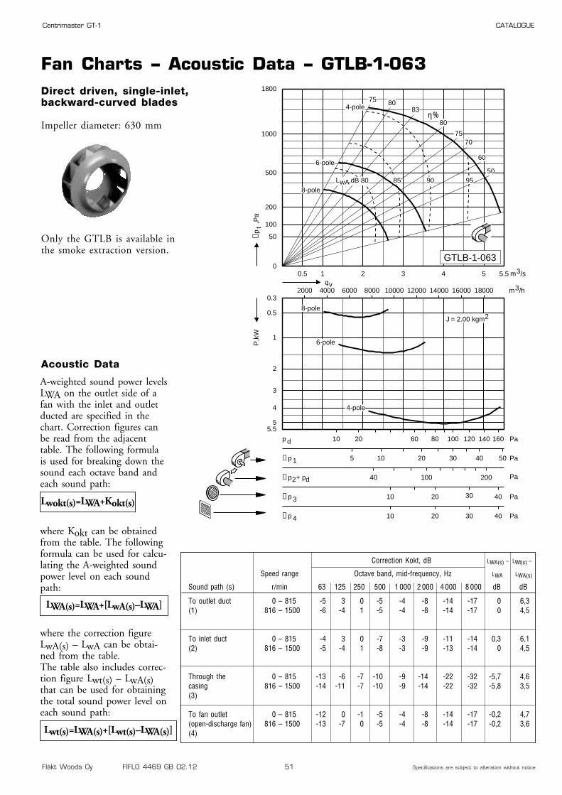
Fläkt Woods Oy FIFLO 4469 GB 02.12 51 Specifications are subject to alteration without notice
Centrimaster GT-1 CATALOGUE
Fan Charts – Acoustic Data – GTLB-1-063Direct driven, single-inlet,backward-curved blades
Impeller diameter: 630 mm
Only the GTLB is available inthe smoke extraction version.
0.5 1 2 3 4 5 5.50
50
100
200
500
1000
1800
0.3
0.5
1
2
3
4
55.5
2000 4000 6000 8000 10000 12000 14000 16000 18000
10 20 60 80 100 120 140 160p d Pa
40 100 200∆p2+ pd Pa
10 20 40∆p 3 Pa
5 10 20 30 40 50∆p 1 Pa
10 20 30
30
40∆p 4 Pa
50
60
7075
80
838075
η%
4-pole
6-pole
8-pole
qvm3/h
m3/s
= 2.00 kgm2
∆pt
,Pa
P,k
W
4-pole
6-pole
8-pole,dB 80 85 90 95LwA
J
GTLB-1-063
Correction Kokt, dB LWA(s) – LWt(s) –
Speed range Octave band, mid-frequency, Hz LWA LWA(s)
Sound path (s) r/min 63 125 250 500 1 000 2 000 4 000 8 000 dB dB
To outlet duct 0 – 815 -5 3 0 -5 -4 -8 -14 -17 0 6,3(1) 816 – 1500 -6 -4 1 -5 -4 -8 -14 -17 0 4,5
To inlet duct 0 – 815 -4 3 0 -7 -3 -9 -11 -14 0,3 6,1(2) 816 – 1500 -5 -4 1 -8 -3 -9 -13 -14 0 4,5
Through the 0 – 815 -13 -6 -7 -10 -9 -14 -22 -32 -5,7 4,6casing 816 – 1500 -14 -11 -7 -10 -9 -14 -22 -32 -5,8 3,5(3)
To fan outlet 0 – 815 -12 0 -1 -5 -4 -8 -14 -17 -0,2 4,7(open-discharge fan) 816 – 1500 -13 -7 0 -5 -4 -8 -14 -17 -0,2 3,6(4)
A-weighted sound power levelsLWA on the outlet side of afan with the inlet and outletducted are specified in thechart. Correction figures canbe read from the adjacenttable. The following formulais used for breaking down thesound each octave band andeach sound path:
where Kokt can be obtainedfrom the table. The followingformula can be used for calcu-lating the A-weighted soundpower level on each soundpath:
where the correction figureLwA(s) – LwA can be obtai-ned from the table.The table also includes correc-tion figure Lwt(s) – LwA(s)that can be used for obtainingthe total sound power level oneach sound path:
Lwokt(s)=LWA+Kokt(s)
Acoustic Data
LWA(s)=LWA+[LwA(s)–LWA]
Lwt(s)=LWA(s)+[Lwt(s)–LWA(s)]

Fläkt Woods Oy FIFLO 4469 GB 02.12 52 Specifications are subject to alteration without notice
Centrimaster GT-1 CATALOGUE
Dimensions and Weights – Motor Data – GTLB-1-071
4 11 160M APAL-4-01100-c-d 1460 75,0 HULB-1-071-c-42-06 3 132S APAL-6-00300-c-d 960 39,0 HULB-1-071-c-38-08 1,1 100 LB APAL-8-90110-c-d 700 23,0 HULB-1-071-c-28-0
Dimensions and Weights
Motor data
Right-hand version with 90°direction of discharge shown
Right-hand version (viewed from drive side)
Left-hand version (same dimensions as the right-hand version)
526
466496
937
928898
505
958
4 x 232
232132
ø10
ø10
15
15
15
19,5
4,5
19,5
Outlet flange
1119
485 458
ø 30
36
57
30
1067
526
ø 710
898
426202
923
973
518
579
1354
875
557
1322 1119
1348
956 485
797
1147
662
981
823504
90° 0° 270°
11
1)
Numberof
polesRated output
kWIECSize
Motor code Speed Weight,kg
Weight (kg) GTLB-1-071: 120,5
Hub code
Motor code: c, d: see ordering codespage 59Hub code: c = 1, right-hand version
c = 2, left-hand versionrande
Remark
1) With max. motor size

Fläkt Woods Oy FIFLO 4469 GB 02.12 53 Specifications are subject to alteration without notice
Centrimaster GT-1 CATALOGUE
Fan Charts – Acoustic Data – GTLB-1-071Direct driven, single-inlet,backward-curved blades
Impeller diameter: 710 mm
Only the GTLB is available inthe smoke extraction version.
0.5 1 2 3 4 5 6 7 7.550
100
200
500
1000
2000
0.550.75
1.1
1.5
2.2
3
4
5.5
7.5
11
2000 4000 6000 10000 14000 18000 22000 26000
10 20 60 80 100 140 180p d Pa
40 100 200∆p2+ pd Pa
10 20 40∆p 3 Pa
5 10 20 30 40 50∆p 1 Pa
10 20 40∆p 4 Pa
50
60
75
80
838075
η%
4-pole
6-pole
8-pole
qvm3/h
m3/s
J = 4.50 kgm2
∆pt
,Pa
P,k
W
4-pole
6-pole
8-pole
,dB 80 85 90 95LwA
GTLB-1-071
Correction Kokt, dB LWA(s) – LWt(s) –
Speed range Octave band, mid-frequency, Hz LWA LWA(s)
Sound path (s) r/min 63 125 250 500 1 000 2 000 4 000 8 000 dB dB
To outlet duct 0 – 815 -5 2 -1 -4 -4 -9 -14 -20 0 5,6(1) 816 – 1500 -5 -6 -1 -4 -3 -9 -15 -20 0 3,9
To inlet duct 0 – 815 -3 2 -1 -6 -5 -9 -14 -19 -1,0 6,6(2) 816 – 1500 -3 -5 0 -7 -5 -10 -14 -19 -1,3 5,3
Through the 0 – 815 -13 -6 -7 -9 -9 -15 -22 -35 -5,7 4,7casing 816 – 1500 -13 -13 -7 -9 -8 -15 -23 -35 -5,3 3,2(3)
To fan outlet 0 – 815 -11 -1 -2 -4 -4 -9 -14 -20 -0,4 4,3(open-discharge fan) 816 – 1500 -11 -9 -2 -4 -3 -9 -15 -20 0 2,8(4)
A-weighted sound power levelsLWA on the outlet side of afan with the inlet and outletducted are specified in thechart. Correction figures canbe read from the adjacenttable. The following formulais used for breaking down thesound each octave band andeach sound path:
where Kokt can be obtainedfrom the table. The followingformula can be used for calcu-lating the A-weighted soundpower level on each soundpath:
where the correction figureLwA(s) – LwA can be obtai-ned from the table.The table also includes correc-tion figure Lwt(s) – LwA(s)that can be used for obtainingthe total sound power level oneach sound path:
Lwokt(s)=LWA+Kokt(s)
Acoustic Data
LWA(s)=LWA+[LwA(s)–LWA]
Lwt(s)=LWA(s)+[Lwt(s)–LWA(s)]
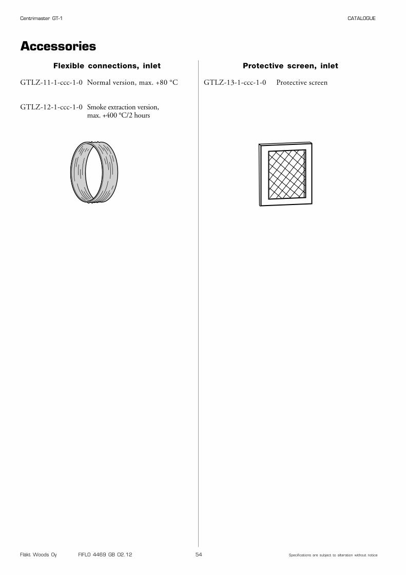
Fläkt Woods Oy FIFLO 4469 GB 02.12 54 Specifications are subject to alteration without notice
Centrimaster GT-1 CATALOGUE
AccessoriesProtective screen, inlet
GTLZ-13-1-ccc-1-0 Protective screen
Flexible connections, inlet
GTLZ-11-1-ccc-1-0 Normal version, max. +80 °C
GTLZ-12-1-ccc-1-0 Smoke extraction version,max. +400 °C/2 hours
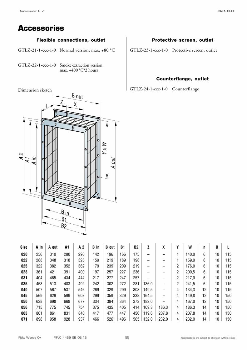
Fläkt Woods Oy FIFLO 4469 GB 02.12 55 Specifications are subject to alteration without notice
Centrimaster GT-1 CATALOGUE
AccessoriesFlexible connections, outlet
GTLZ-21-1-ccc-1-0 Normal version, max. +80 °C
GTLZ-22-1-ccc-1-0 Smoke extraction version,max. +400 °C/2 hours
Dimension sketch
Z X
B out
L
A 2
A1 A in
A ou
t
Y x
W
B inB1B2
Protective screen, outlet
GTLZ-23-1-ccc-1-0 Protective screen, outlet
Counterflange, outlet
GTLZ-24-1-ccc-1-0 Counterflange
Size A in A out A1 A 2 B in B out B1 B2 Z X Y W n D L
020 256 310 280 290 142 196 166 175 – – 1 140,0 6 10 115022 288 348 318 328 159 219 189 198 – – 1 159,0 6 10 115025 322 382 352 362 179 239 209 219 – – 2 176,0 6 10 115028 361 421 391 400 197 257 227 236 – – 2 200,5 6 10 115031 404 465 434 444 217 277 247 257 – – 2 217,0 6 10 115035 453 513 483 492 242 302 272 281 136,0 – 2 241,5 6 10 115040 507 567 537 546 269 329 299 308 149,5 – 4 134,3 12 10 115045 569 629 599 608 299 359 329 338 164,5 – 4 149,8 12 10 150050 638 698 668 677 334 394 364 373 182,0 – 4 167,0 12 10 150056 715 775 745 754 375 435 405 414 109,3 186,3 4 186,3 14 10 150063 801 861 831 840 417 477 447 456 119,6 207,8 4 207,8 14 10 150071 898 958 928 937 466 526 496 505 132,0 232,0 4 232,0 14 10 150
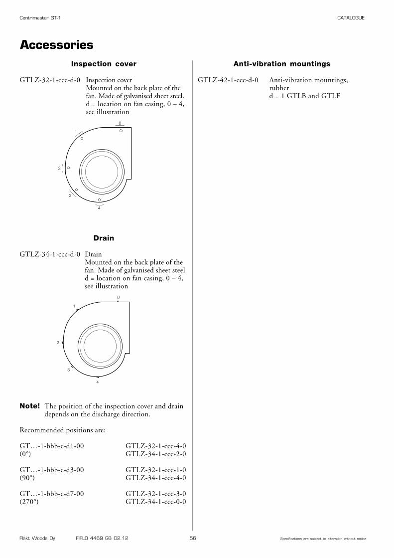
Fläkt Woods Oy FIFLO 4469 GB 02.12 56 Specifications are subject to alteration without notice
Centrimaster GT-1 CATALOGUE
Anti-vibration mountings
GTLZ-42-1-ccc-d-0 Anti-vibration mountings,rubberd = 1 GTLB and GTLF
Inspection cover
GTLZ-32-1-ccc-d-0 Inspection coverMounted on the back plate of the fan. Made of galvanised sheet steel.d = location on fan casing, 0 – 4, see illustration
0
1
2
3
4
Drain
GTLZ-34-1-ccc-d-0 DrainMounted on the back plate of the fan. Made of galvanised sheet steel.d = location on fan casing, 0 – 4, see illustration
0
1
2
3
4
Accessories
Note! The position of the inspection cover and draindepends on the discharge direction.
Recommended positions are:
GT…-1-bbb-c-d1-00 GTLZ-32-1-ccc-4-0(0°) GTLZ-34-1-ccc-2-0
GT…-1-bbb-c-d3-00 GTLZ-32-1-ccc-1-0(90°) GTLZ-34-1-ccc-4-0
GT…-1-bbb-c-d7-00 GTLZ-32-1-ccc-3-0(270°) GTLZ-34-1-ccc-0-0
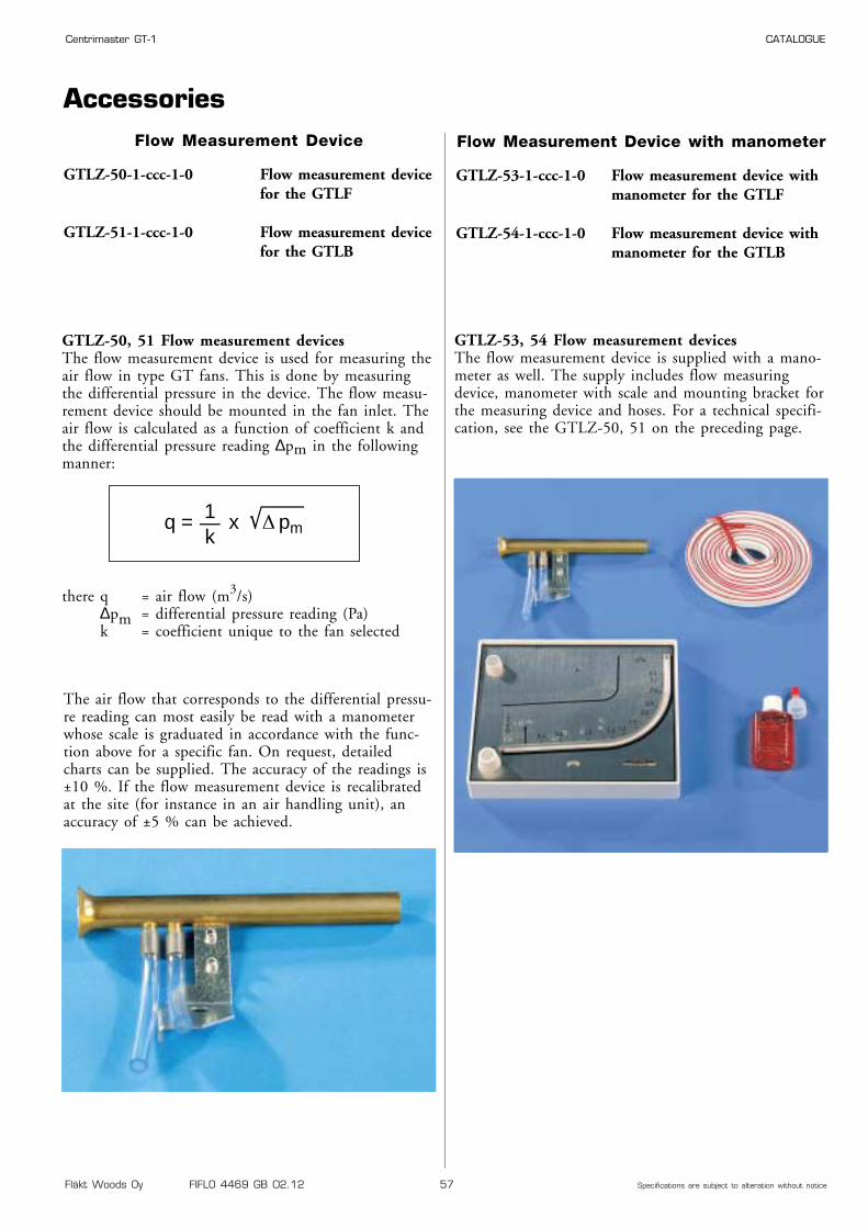
Fläkt Woods Oy FIFLO 4469 GB 02.12 57 Specifications are subject to alteration without notice
Centrimaster GT-1 CATALOGUE
AccessoriesFlow Measurement Device
GTLZ-50-1-ccc-1-0 Flow measurement devicefor the GTLF
GTLZ-51-1-ccc-1-0 Flow measurement devicefor the GTLB
GTLZ-50, 51 Flow measurement devicesThe flow measurement device is used for measuring theair flow in type GT fans. This is done by measuringthe differential pressure in the device. The flow measu-rement device should be mounted in the fan inlet. Theair flow is calculated as a function of coefficient k andthe differential pressure reading ∆pm in the followingmanner:
there q = air flow (m3/s)∆pm = differential pressure reading (Pa)k = coefficient unique to the fan selected
The air flow that corresponds to the differential pressu-re reading can most easily be read with a manometerwhose scale is graduated in accordance with the func-tion above for a specific fan. On request, detailedcharts can be supplied. The accuracy of the readings is±10 %. If the flow measurement device is recalibratedat the site (for instance in an air handling unit), anaccuracy of ±5 % can be achieved.
q = x pm1—k
Flow Measurement Device with manometer
GTLZ-53-1-ccc-1-0 Flow measurement device withmanometer for the GTLF
GTLZ-54-1-ccc-1-0 Flow measurement device withmanometer for the GTLB
GTLZ-53, 54 Flow measurement devicesThe flow measurement device is supplied with a mano-meter as well. The supply includes flow measuringdevice, manometer with scale and mounting bracket forthe measuring device and hoses. For a technical specifi-cation, see the GTLZ-50, 51 on the preceding page.
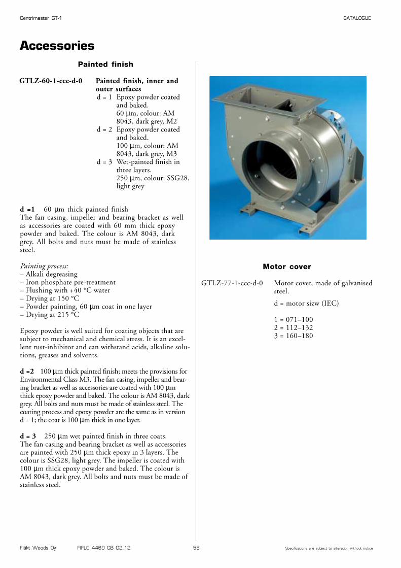
Fläkt Woods Oy FIFLO 4469 GB 02.12 58 Specifications are subject to alteration without notice
Centrimaster GT-1 CATALOGUE
Painted finish
GTLZ-60-1-ccc-d-0 Painted finish, inner andouter surfacesd = 1 Epoxy powder coated
and baked.60 µm, colour: AM 8043, dark grey, M2
d = 2 Epoxy powder coatedand baked.100 µm, colour: AM 8043, dark grey, M3
d = 3 Wet-painted finish inthree layers.250 µm, colour: SSG28,light grey
d =1 60 µm thick painted finishThe fan casing, impeller and bearing bracket as wellas accessories are coated with 60 mm thick epoxypowder and baked. The colour is AM 8043, darkgrey. All bolts and nuts must be made of stainlesssteel.
Painting process:– Alkali degreasing– Iron phosphate pre-treatment– Flushing with +40 °C water– Drying at 150 °C– Powder painting, 60 µm coat in one layer– Drying at 215 °C
Epoxy powder is well suited for coating objects that aresubject to mechanical and chemical stress. It is an excel-lent rust-inhibitor and can withstand acids, alkaline solu-tions, greases and solvents.
d =2 100 µm thick painted finish; meets the provisions forEnvironmental Class M3. The fan casing, impeller and bear-ing bracket as well as accessories are coated with 100 µmthick epoxy powder and baked. The colour is AM 8043, darkgrey. All bolts and nuts must be made of stainless steel. Thecoating process and epoxy powder are the same as in version d = 1; the coat is 100 µm thick in one layer.
d = 3 250 µm wet painted finish in three coats.The fan casing and bearing bracket as well as accessoriesare painted with 250 µm thick epoxy in 3 layers. Thecolour is SSG28, light grey. The impeller is coated with100 µm thick epoxy powder and baked. The colour isAM 8043, dark grey. All bolts and nuts must be made ofstainless steel.
Accessories
Motor cover
GTLZ-77-1-ccc-d-0 Motor cover, made of galvanisedsteel.
d = motor sizw (IEC)
1 = 071–1002 = 112–1323 = 160–180
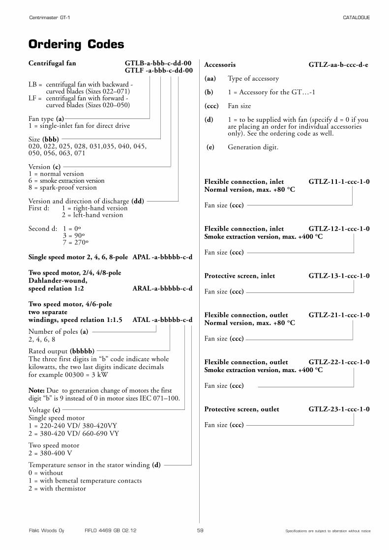
Fläkt Woods Oy FIFLO 4469 GB 02.12 59 Specifications are subject to alteration without notice
Centrimaster GT-1 CATALOGUE
Accessoris GTLZ-aa-b-ccc-d-e
(aa) Type of accessory
(b) 1 = Accessory for the GT…-1
(ccc) Fan size
(d) 1 = to be supplied with fan (specify d = 0 if youare placing an order for individual accessoriesonly). See the ordering code as well.
(e) Generation digit.
Ordering CodesCentrifugal fan GTLB-a-bbb-c-dd-00
GTLF -a-bbb-c-dd-00
LB = centrifugal fan with backward - curved blades (Sizes 022–071)
LF = centrifugal fan with forward - curved blades (Sizes 020–050)
Fan type (a)1 = single-inlet fan for direct drive
Size (bbb)020, 022, 025, 028, 031,035, 040, 045, 050, 056, 063, 071
Version (c)1 = normal version6 = smoke extraction version8 = spark-proof version
Version and direction of discharge (dd)First d: 1 = right-hand version
2 = left-hand version
Second d: 1 = 0º3 = 90º7 = 270º
Single speed motor 2, 4, 6, 8-pole APAL -a-bbbbb-c-d
Two speed motor, 2/4, 4/8-poleDahlander-wound,speed relation 1:2 ARAL-a-bbbbb-c-d
Two speed motor, 4/6-poletwo separate windings, speed relation 1:1.5 ATAL -a-bbbbb-c-d
Number of poles (a)2, 4, 6, 8
Rated output (bbbbb)The three first digits in “b” code indicate wholekilowatts, the two last digits indicate decimalsfor example 00300 = 3 kW
Note: Due to generation change of motors the first digit “b” is 9 instead of 0 in motor sizes IEC 071–100.
Voltage (c)Single speed motor1 = 220-240 VD/ 380-420VY2 = 380-420 VD/ 660-690 VY
Two speed motor2 = 380-400 V
Temperature sensor in the stator winding (d)0 = without1 = with bemetal temperature contacts2 = with thermistor
Flexible connection, inlet GTLZ-11-1-ccc-1-0Normal version, max. +80 °C
Fan size (ccc)
Flexible connection, inlet GTLZ-12-1-ccc-1-0Smoke extraction version, max. +400 °C
Fan size (ccc)
Protective screen, inlet GTLZ-13-1-ccc-1-0
Fan size (ccc)
Flexible connection, outlet GTLZ-21-1-ccc-1-0Normal version, max. +80 °C
Fan size (ccc)
Flexible connection, outlet GTLZ-22-1-ccc-1-0Smoke extraction version, max. +400 °C
Fan size (ccc)
Protective screen, outlet GTLZ-23-1-ccc-1-0
Fan size (ccc)
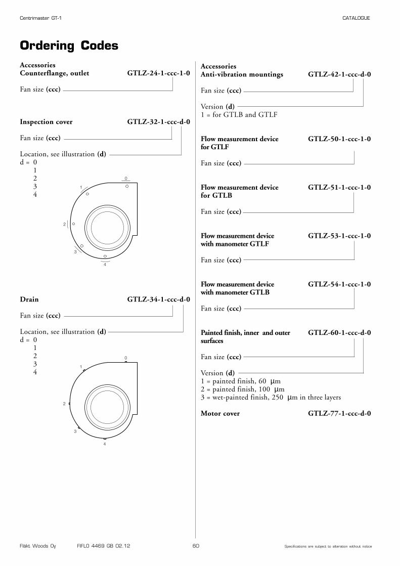
Fläkt Woods Oy FIFLO 4469 GB 02.12 60 Specifications are subject to alteration without notice
Centrimaster GT-1 CATALOGUE
Ordering Codes
Inspection cover GTLZ-32-1-ccc-d-0
Fan size (ccc)
Location, see illustration (d)d = 0
1234
Drain GTLZ-34-1-ccc-d-0
Fan size (ccc)
Location, see illustration (d)d = 0
1234
AccessoriesAnti-vibration mountings GTLZ-42-1-ccc-d-0
Fan size (ccc)
Version (d)1 = for GTLB and GTLF
Flow measurement device GTLZ-50-1-ccc-1-0for GTLF
Fan size (ccc)
Flow measurement device GTLZ-51-1-ccc-1-0for GTLB
Fan size (ccc)
Flow measurement device GTLZ-53-1-ccc-1-0with manometer GTLF
Fan size (ccc)
Flow measurement device GTLZ-54-1-ccc-1-0with manometer GTLB
Fan size (ccc)
Painted finish, inner and outer GTLZ-60-1-ccc-d-0surfaces
Fan size (ccc)
Version (d)1 = painted finish, 60 µm2 = painted finish, 100 µm3 = wet-painted finish, 250 µm in three layers
Motor cover GTLZ-77-1-ccc-d-0
0
1
2
3
4
0
1
2
3
4
AccessoriesCounterflange, outlet GTLZ-24-1-ccc-1-0
Fan size (ccc)

Fläkt Woods Oy, Kalevantie 39, FI-205 20 Turku, Finland
t +358-102 230 000 f +358-102 233 475w www.flaktwoods.com
FIFL
O 4
469 G
B 0
2.1
2te
lesk
op r
ekla
mbyr
å
036-3
0 8
3 8
0