Centrifugal Pumps Type - Klaus Union · 2009-09-21 · The sealless centrifugal pump SLM GV is a...
39
KLAUS UNION D-44795 BOCHUM BLUMENFELDSTRASSE 18 +49 (0) 234 45 95 – 0 TELEFAX +49 (0) 234 43 23 87 www.klaus-union.de Operation Manual for Centrifugal Pumps Type SLM GV Edition 07/2001 O:\BA\Slm_gv\Englisch\DECKBLATT_E.doc
Transcript of Centrifugal Pumps Type - Klaus Union · 2009-09-21 · The sealless centrifugal pump SLM GV is a...

KLAUS UNION D-44795 BOCHUM BLUMENFELDSTRASSE 18 � +49 (0) 234 45 95 – 0 TELEFAX +49 (0) 234 43 23 87 www.klaus-union.de
O p e r a t i o n M a n u a l
for
Centrifugal Pumps Type
SLM GV
Edition 07/2001
O:\BA\Slm_gv\Englisch\DECKBLATT_E.doc

Edition 07/2001
Contents of Operation Manual 1. General BA/E: 23000-01/..
2. Safety BA/E: 01000-02/..
3. Transport Preservation and Storage BA/E: 01000-03/..
4. Constructional Description BA/E: 23000-04/..
5. Installation and Assembly BA/E: 23000-05/..
6. Commissioning and Shutdown BA/E: 23000-06/..
7. Maintenance BA/E: 23000-07/..
8. Malfunctions; Causes and Elimination BA/E: 01000-08/..
General
BA/E-23000-01/2
Page 1 of 1
07/2001
C o n t e n t s P a g e 1. Introduction _______________________________________________ 1 2. Operative Range ___________________________________________ 1 3. Copyright _________________________________________________ 1
1. Introduction This operation manual refers to centrifugal pumps type SLM GV. Prior to commissioning of the pump, this operation manual is to be read and its instructions are to be followed precisely by the operational staff (erecting staff and operators). Only a complete understanding of this manual and its contents can avoid expensive damage to the pump and assure a long trouble-free operating life. It is therefore extremely important that this manual is made available to all personnel who are involved with installation, operation or maintenance of the pumps. Any information and descriptions given in this manual are correct at the time of issue. However, they are subject to technical modifications resulting in an improvement of KLAUS-UNION products. 2. Operative Range The sealless centrifugal pump SLM GV is a centrifugal pump with magnet drive. By means of its characteristic feature – the permanent magnetic synchronous drive – this pump fulfils all requirements of environmental care. Therefore, it is used in all fields of the chemical and petrochemical industries for a leak-free processing of aggressive, explosive or toxic liquids. The pump is designed to provide reliable, trouble-free, and dependable operation even under the most arduous conditions.
3. Copyright This operation manual is a copyright of KLAUS-UNION. This operation manual includes technical information and drawings that remain the property of KLAUS-UNION. They must neither in whole nor in part be reproduced, exploited nor transmitted to third parties for the purpose of competition.
Klaus-Union Armaturen Pumpen GmbH & Co. KG P.O. Box 10 13 49 D-44713 Bochum Phone : +49 (0) 234 45 95 – 0 Fax : +49 (0) 234 43 23 87 Internet : www.klaus-union.de

Safety
BA/E-01000-02/0
Page 1 of 2
C o n t e n t s P a g e 1. General __________________________________________________ 1 2. Marking of References in this Operation Manual___________________ 1 3. Qualification and Training of Staff ______________________________ 1 4. Dangers of Non-Compliance with Safety Instructions _______________ 2 5. Safety-Conscious Work ______________________________________ 2 6. Safety Instructions for Operating Company/Operator _______________ 2 7. Safety Instructions for Maintenance, Inspection and Assembly________ 2 8. Unauthorised Modification and Production of Spare Parts ___________ 2 9. Inadmissible Operating Modes ________________________________ 2
1. General This manual contains all basic instructions for the installation, operating and maintenance of the pump. It should be read and fully understood by all installation, commissioning, operating and maintenance personnel before the pump is operated. It is recommended that the manual is always available at the point of operation of the unit. Not only the general safety instructions as mentioned in the section "Safety" of the operation manual have to be observed but also the special safety instructions to be found under the other main headlines. 2. Marking of References in this Operation Manual The safety instructions mentioned in this operation manual are marked with the general danger sign according to DIN 4844-W9 and the special sign according to DIN 4844-W8 warning of electric tension. Non-compliance with safety instructions may cause danger to people.
To mark safety instructions and the dangers to the machine and its functions which can be caused in case of non-compliance the word
A T T E N T I O N has been inserted. References made on the machine itself, such as direction-of-rotation arrow marks for fluid connections must by all means be observed and kept completely legible. 3. Qualification and Training of Staff The staff responsible for installation, commissioning, operation, and maintenance must have the appropriate qualifications to enable them to carry out these duties. The scope, competence and control of the staff is the responsibility of the operating company. If the staff are not fully conversant with magnetic drive pumps they should be given training and instruction. If required this training is available from the manufacturer/supplier of the equipment by arrangement. It is the operating company's responsibility to ensure that all staff are fully aware of and understand the contents of this manual.
Safety
BA/E-01000-02/0
Page 2 of 2
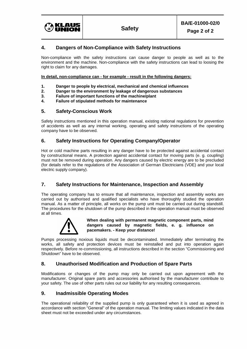
4. Dangers of Non-Compliance with Safety Instructions Non-compliance with the safety instructions can cause danger to people as well as to the environment and the machine. Non-compliance with the safety instructions can lead to loosing the right to claim for any damages. In detail, non-compliance can - for example - result in the following dangers: 1. Danger to people by electrical, mechanical and chemical influences 2. Danger to the environment by leakage of dangerous substances 3. Failure of important functions of the machine/plant 4. Failure of stipulated methods for maintenance 5. Safety-Conscious Work Safety instructions mentioned in this operation manual, existing national regulations for prevention of accidents as well as any internal working, operating and safety instructions of the operating company have to be observed. 6. Safety Instructions for Operating Company/Operator Hot or cold machine parts resulting in any danger have to be protected against accidental contact by constructional means. A protection against accidental contact for moving parts (e. g. coupling) must not be removed during operation. Any dangers caused by electric energy are to be precluded (for details refer to the regulations of the Association of German Electricians (VDE) and your local electric supply company). 7. Safety Instructions for Maintenance, Inspection and Assembly The operating company has to ensure that all maintenance, inspection and assembly works are carried out by authorised and qualified specialists who have thoroughly studied the operation manual. As a matter of principle, all works on the pump unit must be carried out during standstill. The procedures for the shutdown of the pump described in the operation manual must be observed at all times.
When dealing with permanent magnetic component parts, mind dangers caused by magnetic fields, e. g. influence on pacemakers. - Keep your distance!
Pumps processing noxious liquids must be decontaminated. Immediately after terminating the works, all safety and protection devices must be reinstalled and put into operation again respectively. Before re-commissioning, all instructions described in the section "Commissioning and Shutdown" have to be observed. 8. Unauthorised Modification and Production of Spare Parts Modifications or changes of the pump may only be carried out upon agreement with the manufacturer. Original spare parts and accessories authorised by the manufacturer contribute to your safety. The use of other parts rules out our liability for any resulting consequences. 9. Inadmissible Operating Modes The operational reliability of the supplied pump is only guaranteed when it is used as agreed in accordance with section "General" of the operation manual. The limiting values indicated in the data sheet must not be exceeded under any circumstances.

Transport,
Preservation and Storage
BA/E-01000-03/1
Page 1 of 2 03/2000
C o n t e n t s P a g e 1. Preservation ____________________________________________ 1 2. Depreservation __________________________________________ 1 3. Protection against Damage and Dirt__________________________ 1 4. Packing ________________________________________________ 2 5. Degree of Disaggregation__________________________________ 2 6. Sensitivity ______________________________________________ 2 7. Intermediate Storage _____________________________________ 2 8. Delivery ________________________________________________ 2
1. Preservation 1.1 Drive shafts 1.1.1 Drive shafts for pumps supplied without couplings
- bare parts are protected against corrosion with "RUST-BAN 391" 1.1.2 Drive shafts supplied as spare parts
- completely protected against corrosion with "RUST-BAN 391" 1.2 Pump parts made of GG, GGG, and GS-C
- all surfaces in contact with the liquid are protected against corrosion with "RUST-BAN 391"
1.3 Deliveries for overseas destinations
- all specified parts are protected against corrosion with "TECTYL 864" 2. Depreservation 2.1 "RUST-BAN 391"
- by means of solvents (e. g. kinds of ESSOVARSOL) aqueous industrial cleaner 2.2 "TECTYL 846"
- with benzine, petroleum, special solvents 3. Protection against Damage and Dirt 3.1 Drive shafts 3.1.1 Drive shafts for pumps supplied without couplings
- the shaft end is protected against damage with a plastic cap 3.1.2 Drive shafts supplied as spare parts
- the shaft end is protected against damages with a plastic cap - the complete shaft is protected against damages with woven textile
3.2 Pump casings Pump casings of completely assembled pumps Pump casings supplied as spare parts
- suction and discharge flanges are closed with flange covers as a protection against damage and dirt
The flange covers meet the safety regulations of the Chemical Industry.

Transport,
Preservation and Storage
BA/E-01000-03/1
Page 2 of 2 03/2000
4. Packing The transport route is decisive for the packaging material. If not particularly stipulated in the contract, the packing corresponds with the packaging regulations HPE laid down by the Bundesverband Holzmittel, Paletten, Exportverpackung e. V. (Federal Association Wood for Packaging, Pallets, Export Packaging Inc.) and the VDMA (Association of German Engineering Shops). The graphical symbols attached to the packing have to be observed. E. g.:
Top Fragile Keep dry Store away from heat
Use no hooks Gravity center Post here 5. Degree of Disaggregation The degree of disaggregation depends upon the size of the unit, the transport used, the local conditions and the lifting equipment available. In principle, it is possible to disassemble the pump into several sub-assemblies. It is our policy, however, to ship the pump in as complete a unit as possible. If the pump is dispatched as sub-assemblies, refer to the drawing enclosed with the packing list for degree of disaggregation and assembly. 6. Sensitivity Transport the pump carefully to avoid damage. According to the transport mode and duration, appropriate transport safety devices are provided for. During transport, shocks and impacts are to be avoided. The pump itself is to be treated with the usual care. 7. Intermediate Storage Store the pump carefully in a safe place and free from vibrations. For this purpose, it is to be duly covered so that no dust and no humidity may penetrate. The parts of the pump are to be provided with a preservative protecting the pump for about a year. If the intermediate storage lasts longer than a year, preservation has to be renewed. 8. Delivery The contents of each packing unit is mentioned in the packing lists which have to be checked for completeness upon receipt. Any shipping damage and/or missing items have to be advised immediately in writing.

Constructional Description
BA/E-23000-04/2
Page 1 of 9 07/2001
C o n t e n t s P a g e 1. General Description _________________________________________1 2. Construction and Operating Action ______________________________1 2.1 Pump Identification Marking ___________________________________2 3. Constructive Design _________________________________________3 3.1 Pump Casing_______________________________________________5 3.2 Suction and Pressure Stages __________________________________5 3.3 Impellers __________________________________________________5 3.4 Journal Bearing _____________________________________________5 3.5 Isolation Shell ______________________________________________5 3.6 Magnetic Drive _____________________________________________6 3.7 Intermediate Lantern _________________________________________6 3.8 Bearing Support ____________________________________________7 3.8.1 Bearing Sealing for Grease Lubricated Construction ________________7 3.8.2 Bearing Support for Oil Lubricated Construction____________________7 3.9 Thermal Barrier with Secondary Sealing__________________________8 4. Flushing System ____________________________________________9 4.1 Flush Flow Temperature Rise__________________________________9
1. General Description The sealless centrifugal pump type SLM GV is a centrifugal multi-stage casing pump of multi-stage casing construction equipped with magnetic coupling. The axial thrust is compensated by means of balancing holes in the impellers. Depending on the duty point, the pump is constructed with an adequate number of stages. 2. Construction and Operating Action The special feature of this centrifugal pump is a permanent magnetic synchronous coupling. The outer magnet carrier (part no. 818.1) connected to the drive shaft (part no. 213) transmits the required torque onto the inner magnet carrier (part no. 818.2) connected to the impeller (part no. 230) without slip. Between the outer magnet carrier (part no. 818.1) and the inner magnet carrier (part no. 818.2) the isolation shell (part no. 817) is located constricting the space filled with the pumped liquid. If the load is greater than the maximum torque of the magnetic coupling the transmission is interrupted, i. e. the magnetic drive de-energizes. Slipping of the coupling does not, however, demagnetise the magnets but it is possible that in the absence of internal recirculation the isolation shell (part no. 817) and the magnets become damaged. Two separate recirculation circuits lubricate the hydrodynamic journal bearings and control the heat dissipation at the isolation shell (part no. 817). The rotating magnet system generates an eddy current in the isolation shell thus causing a temperature increase of the pumped liquid. The outer magnet carrier runs in anti-friction bearings. Depending on the operating temperature the following magnet systems and anti-friction bearings are used: Magnet System Temperature Range Anti-Friction Bearing SE system -120 °C up to +250 °C grease or oil lubricated SE system +250 °C up to +300 °C oil lubricated

Constructional Description
BA/E-23000-04/2
Page 2 of 9 07/2001
2.1 Pump Identification Marking
SLM GVS 065-032-160 / 3 - 09E03 W Line of Products
Bearing Support Construction
Nominal Dia. Suction Nozzle
Nominal Dia. Discharge Nozzle
Nominal Diameter of Impeller
Number of Stages
Size of Magnet Drive Material of Magnets
Length of Magnets
Identification Letters (Construction Types) Legend of identification letters (Construction Types):
S thermal barrier W thermal barrier with secondary sealing F internal filter C isolation shell of material CFRP/PTFE E1 external feeding connection:
- one external connection - internal flush bores with closed back
E2 external flushing/vent connection - one external connection - internal flush bore open
OT pump without flush: - two external connections for feeding and venting - throttle bush on the impeller side
• Designation of the types of bearing support: Bearing Support Type Comments SLM GVS standard Grease lubrication SLM GVO standard Oil lubrication SLM GVB close-coupled pump Motor lantern

Constructional Description
BA/E-23000-04/2
Page 3 of 9 07/2001
3. Constructive Design
SLM GVS (grease lubricated bearing support): 2 to 6 stages

Constructional Description
BA/E-23000-04/2
Page 4 of 9 07/2001
SLM GVO (oil lubricated bearing support): 2 to 6 stages

Constructional Description
BA/E-23000-04/2
Page 5 of 9 07/2001
3.1 Pump Casing The pump casing (part no. 106) disposes of an axial suction nozzle DN 65; the pressure casing (part no. 107) is equipped with a vertical discharge nozzle DN 32 pointing upwards. The flanges are designed to DIN2501 PN40. To fix the pump on the base plate, the pump casings are provided with supporting feet. The casing drain type (drain plug or flange) is indicated on the dimensional drawing. 3.2 Suction and Pressure Stages Depending on the delivery head to be achieved, the centrifugal pump type SLM GV is equipped with a number of impellers ranging between 2 to 6. The first impeller is the so-called suction impeller. The subsequent impellers are called pressure impellers. The suction and pressure casings are held together with the individual stages (part no. 108) by means of tension rods (part no. 905). The individual stages are sealed by means of O-rings (part no. 412.1). 3.3 Impellers The impellers (part no. 230) are designed as radial impellers that are fixed on a single shaft between suction and discharge nozzles. The axial thrust is compensated by means of throttling rings and balancing holes on the impeller back. 3.4 Journal Bearing The rotating parts in the liquid chamber run in a silicon carbide journal bearing (SSiC) consisting of two halves lubricated by the liquid. The journal bearings are designed as radial and axial bearings comprising two thrust bearings (part no. 314), the bearing sleeves (part no. 529.1) and the bearing bush (part no. 545.1). The two SSiC bearing bushes (part 1) have been shrunk fit together with the spacer bush (part 2) into the bearing casing (part 3) and secured against turning. These parts together comprise the bearing bush (part no. 545.1). The two bearing sleeves (part no. 529.1) run in the centring devices of the spacer sleeve (part no. 525). The flexible components (part no. 504.2) compensate for the different thermal expansion of SSiC and stainless steel over the entire thermal application range. 3.5 Isolation Shell The isolation shell (part no. 817) seals the system without any leakage by means of a gasket (part no. 400.3).

Constructional Description
BA/E-23000-04/2
Page 6 of 9 07/2001
3.6 Magnetic Drive The magnetic drive comprises the outer magnet carrier (part no. 818.1) and the inner magnet carrier (part no. 818.2). The magnets on the inner magnet carrier are protected against the pumped liquid by a corrosion resistant cover plate (magnet carrier jacket) so that they have no contact with the pumped liquid.
By mounting a temperature probe PT100 on the bearing support flange, the temperature on the isolation shell can be measured. For this purpose, instead of the drain plug (part no. 903.7), the temperature probe (part no. 620.1) is screwed into the intermediate lantern (part no. 146.1). 3.7 Intermediate Lantern The bearing support (part no. 330) forms the bearing bracket together with the intermediate lantern (part no. 146.1). The intermediate lantern is provided with a rub ring for the outer magnet carrier (part no. 818.1). This ring protects the isolation shell from damage by the outer magnet carrier (part no. 818.1) in case of a defective anti-friction bearing (part no. 321).

Constructional Description
BA/E-23000-04/2
Page 7 of 9 07/2001
3.8 Bearing Support The bearing support (part no. 330) is available in two constructions: • SLM GVS: grease lubricated anti-friction bearing • SLM GVO: oil lubricated anti-friction bearing Additionally, the following pump construction can be supplied: • SLM GVB: close-coupled pump with motor lantern As the bearing support is screwed onto the intermediate lantern (part no. 146.1), it is easily possible to replace the respective bearing support by one of the other two construction types at a later time. In order to use the pump as a close-coupled pump type SLM GVB, the bearing support is replaced by a motor lantern (part no. 146.2). The drive shaft (part no. 213) runs on single-row deep groove ball bearings (part no. 321). 3.8.1 Bearing Sealing for Grease Lubricated Construction The sealing of the grease lubricated ball bearings is effected by means of cover disks; on the motor side, a radial shaft seal ring (part no. 421.2) is installed as a protection against splash water.
3.8.2 Bearing Support for Oil Lubricated Construction The sealing of the oil lubricated ball bearings (part no. 321) on the motor side as a protection against splash water is effected by a radial shaft seal ring (part no. 421.2). Towards the outer magnet carrier (part no. 818.1) the sealing is effected by the secondary sealing (part no. 421.3).

Constructional Description
BA/E-23000-04/2
Page 8 of 9 07/2001
3.9 Thermal Barrier with Secondary Sealing The thermal barrier (part no. 152) is mounted between the bearing support (part no. 330) and the intermediate lantern (part no. 146.1). In case of hot pumped liquids it is the thermal barrier's function to dissipate the product heat to its surroundings. Thus the rise of the anti-friction bearing temperature is reduced. The secondary sealing (part no. 421.3) is used to retain the pumped liquid for a short period if the isolation shell is damaged thus preventing a leakage to the atmosphere. In connection with the grease lubricated bearing support of pump type SLM GVS the secondary sealing can additionally be inserted into the thermal barrier (part no. 152).
As an option, the close-coupled pump type SLM GVB can additionally be equipped with a thermal barrier. In the oil lubricated pump type SLM GVO, the thermal barrier and the secondary sealing are part and parcel of the basic construction.

Constructional Description
BA/E-23000-04/2
Page 9 of 9 07/2001
4. Flushing System
The flush flow lubricates the axial and the radial journal bearings and dissipates the heat generated by the eddy current loss. The flush flow is taken from a point of relative high pressure (P1) and pumped internally via bores to a point of relative low pressure in the impeller (P2). 4.1 Flush Flow Temperature Rise The volume of the flush flow is gauged in such a way that during operation the temperature increase of the flush flow ranges from approx. 1 °C to 5 °C (referenced to aqueous liquids).
A T T E N T I O N
Inadmissible operation modes can cause inadmissible temperature rises, thus producing steam in the liquid.

Installation and Assembly
BA/E-23000-05/1
Page 1 of 4 07/2001
C o n t e n t s P a g e 1. General Instructions ________________________________________1 2. Installation Conditions_______________________________________1 3. Installation of the Completely Assembled Unit ____________________1 4. Installation of the Partially Assembled Pump _____________________2 5. Specific Features of Pumps Processing Hot Liquids _______________3 6. Pipework_________________________________________________3 6.1 Suction-Side Pipework ______________________________________3 6.2 Pressure Pipework _________________________________________4 6.3 Admissible Pipework Forces and Moments ______________________4
1. General Instructions We do not assume any liability for damage due to inexpert assembly. When turning by hand the pump shaft of the pump upon delivery, abradant noises may be heard. These noises result from the grease-free assembly of the journal bearings. Having lubricated the friction partners with the liquid, these noises disappear. Concerning liquid temperatures exceeding 100 °C, please refer to para. 5 of the present operation manual and by all means observe the instructions given therein. The pictorial representations have been simplified. 2. Installation Conditions Make available enough space to facilitate assembly and maintenance. Arrange preceding and succeeding pipings and units correspondingly. For dimensions of the centrifugal pump type SLM GV refer to the attached installation plan. 3. Installation of the Completely Assembled Unit The complete unit consisting of pump, coupling and motor is supplied by KLAUS-UNION already assembled and mounted on a base plate to make sure that the shafts are exactly aligned. Coupling and rotating shaft ends are protected against accidental contact by means of a coupling guard.
Never commission a pump without coupling guard! Risk of injury due to bare rotating parts!
Install the unit according to the foundation plan and align it using a spirit level. Then grout the base plate and the foundation bolts with a fast setting grout-mixture. Only after the grout-mixture has set, the foundation bolts may be tightened while observing the required tightening moment. Upon duly installing the unit connect all pipings - ensuring that they are subject to only low tension - (refer to para. 6 of the present operation manual). Afterwards, check the alignment of the shaft once again.
Prior to commissioning align the shafts properly and exactly. Badly aligned shafts increase the wear of the bearings and the flexible coupling. Moreover, the pump will run unsteadily.

Installation and Assembly
BA/E-23000-05/1
Page 2 of 4 07/2001
4. Installation of the Partially Assembled Pump In case the pump is not supplied as a complete unit but in sub-assemblies such as pump, coupling, motor, and base plate, the installation is effected as described hereafter: insert the key into the key groove of the motor-side shaft end. Fit the motor-side coupling half on the shaft by means of a standard draw-on device. The same goes for the pump-side coupling half. Align the axial distance between motor and pump coupling halves (refer to installation plan and dimension X in u. m. table). Compensate vertical shaft displacements by plane-parallel shims.
X Eliminate misalignment of both coupling halves. Put a straight-edge on approx. 4 opposite points on the circumference of the coupling and refer to the u. m. drawing.
Align couplings with a diameter exceeding 120 mm with the help of a dial gauge.
Compensate a vertical displacement by placing underneath or removing the a. m. plane-parallel shims. Fix pump and motor on the base plate with the bolts provided for that purpose.
Equip the coupling and rotating shaft ends with a protection against accidental contact! Risk of injury due to bare rotating parts!
Install the completely assembled unit as described in para. 3 of the present operation manual.
Coupling Size X in mm
Without Cartridge Unit 58 up to 140 2 - 4 160 up to 225 2 - 6 250 up to 280 2 - 8
With Cartridge Unit
up to 140 5 160 up to 225 6
250 8

Installation and Assembly
BA/E-23000-05/1
Page 3 of 4 07/2001
5. Specific Features of Pumps Processing Hot Liquids When processing hot liquids, a misalignment of the shaft is caused by temperature differences between pump and motor. This shaft misalignment additionally increases the wear of the coupling parts and has an adverse effect on the pump's smoothness of operation. For an appropriate installation of the unit, heat the pump in the plant to its operating temperature. Having shut down the unit, check the axial/radial misalignment of both coupling halves. Prior to measuring the shaft misalignment, release the bolts of the support (part no. 901.6). Compensate the assessed shaft misalignment by putting underneath motor and/or support plane-parallel shims. The following table indicates the pump types and the ranges of temperature requiring a realignment.
SLM GV 100°C to 150°C 150°C to 200°C 200°C to 250°C 250°C to 300°C 065-032-160 ⊗⊗⊗⊗ X X X
⊗ to be aligned in cold condition X to be aligned in warm condition 6. Pipework All pipework connections should be state of the art and designed for the operating conditions. Ensure that the forces and moments transmitted to the pump by the pipework do not exceed the values stipulated - please refer to para. 6.3 of the present operation manual (Admissible Pipework Forces and Moments). The pipework should all be clean and free of all impurities such as weld slag, scale etc. Avoid malfunctions of the pump flow resulting from variable velocity or irrational flow to the pump inlet. Such malfunctions will have an adverse effect on the pump capacity, the NPSH characteristics and the smooth operation of the pump. 6.1 Suction-Side Pipework The construction of the suction-side pipework should have only few baffles (bends, valves, etc.) as these elements are often responsible for variable velocity and eddying. Avoid malfunctions caused by asymmetric feed stream. When modifying nominal diameters use conical sections. If a globe valve is used, it must always be completely open during operation and must never be used to control the flow. Always install the suction pipe ascending to the pump. When dimensioning the suction pipe, ensure that the flow velocity does not exceed 2 m/s. Install the feed pipe descending to the pump. When dimensioning the feed pipe, ensure that the flow velocity does not exceed 2.5 m/s. For liquids being processed close to their boiling point, the flow velocity shall not exceed 0.8 m/s.

Installation and Assembly
BA/E-23000-05/1
Page 4 of 4 07/2001
6.2 Pressure Pipework Install a control valve to adjust the flow directly behind the pump. Install a check valve between pump and globe valve on long pressure pipings or static delivery heads exceeding 10 m. This check valve protects the pump against liquid reflux and runback at shutdown. When dimensioning the pipework, make sure that the flow velocity does not exceed 5 m/s. When modifying nominal diameters use conical sections. 6.3 Admissible Pipework Forces and Moments
Pump on Base Plate Grouted with Cement: The values are valid for the pump alone and the pump installed on a grouted base plate respectively or a pump alone installed on a rigid base plate.
Pump on Base Plate Grouted with Cement
Pump Size Mmax
Mx, My (Nm)
Ph max
Px = Pz ( N )
Pv max
Py ( N )
Pump Size
065-032-160 1000 3000 4500 065-032-160 Pump on Non-Grouted Base Plate: These values are valid for the pump installed on a non-grouted base plate of normal rigidity.
Pump on Non-Grouted Base Plate
Pump Size Mmax
Mx, My (Nm)
Ph max
Px = Pz ( N )
Pv max
Py ( N )
Pump Size
065-032-160 350 2000 2500 065-032-160
Commissioning and Shutdown
BA/E-23000-06/2
Page 1 of 4 07/2001
C o n t e n t s P a g e 1. List of Lubricants ___________________________________________ 1 2. Preparation for Commissioning ________________________________ 2 2.1 Grease-Lubricated Roller Bearings _____________________________ 2 2.2 Oil-Lubricated Roller Bearings _________________________________ 2 2.3 Checking the Direction of Rotation _____________________________ 3 2.4 Filling and Venting __________________________________________ 3 3. Monitoring Equipment _______________________________________ 3 4. Commissioning ____________________________________________ 3 5. Shutdown _________________________________________________ 4 5.1 Preservation and Storage ____________________________________ 4
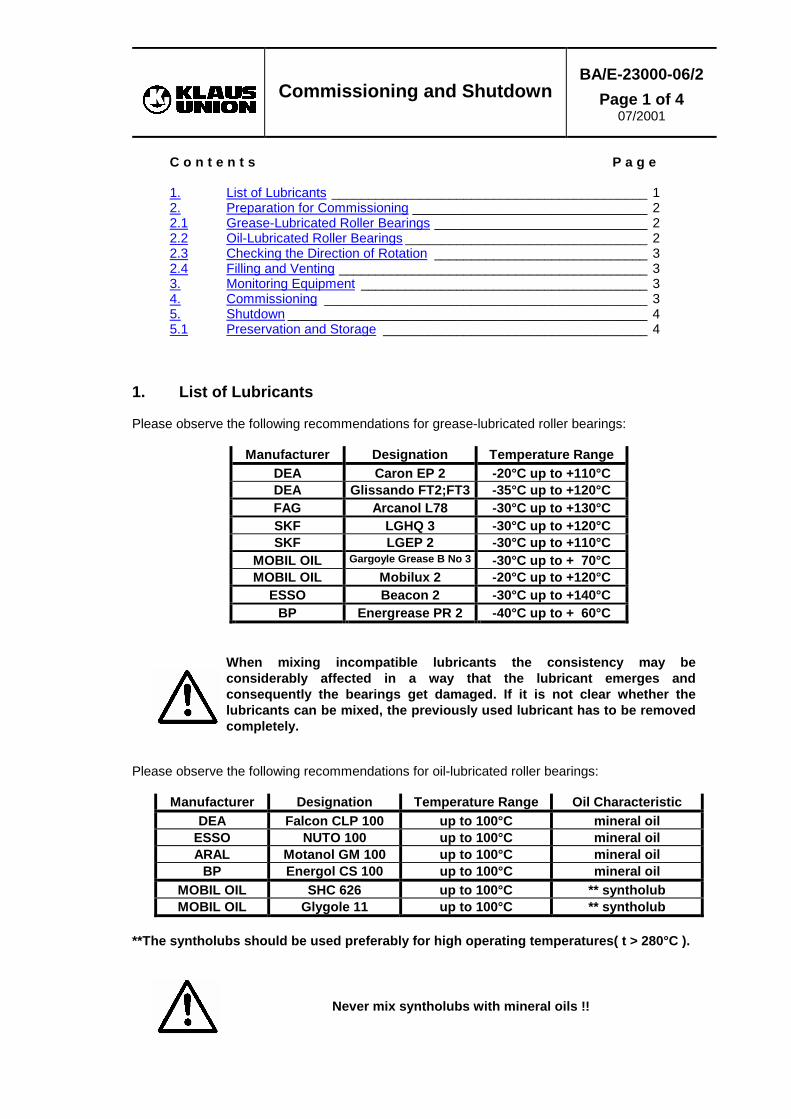
1. List of Lubricants Please observe the following recommendations for grease-lubricated roller bearings:
Manufacturer Designation Temperature Range DEA Caron EP 2 -20°C up to +110°C DEA Glissando FT2;FT3 -35°C up to +120°C FAG Arcanol L78 -30°C up to +130°C SKF LGHQ 3 -30°C up to +120°C SKF LGEP 2 -30°C up to +110°C
MOBIL OIL Gargoyle Grease B No 3 -30°C up to + 70°C MOBIL OIL Mobilux 2 -20°C up to +120°C
ESSO Beacon 2 -30°C up to +140°C BP Energrease PR 2 -40°C up to + 60°C
When mixing incompatible lubricants the consistency may be considerably affected in a way that the lubricant emerges and consequently the bearings get damaged. If it is not clear whether the lubricants can be mixed, the previously used lubricant has to be removed completely.
Please observe the following recommendations for oil-lubricated roller bearings:
Manufacturer Designation Temperature Range Oil Characteristic DEA Falcon CLP 100 up to 100°C mineral oil
ESSO NUTO 100 up to 100°C mineral oil ARAL Motanol GM 100 up to 100°C mineral oil
BP Energol CS 100 up to 100°C mineral oil MOBIL OIL SHC 626 up to 100°C ** syntholub MOBIL OIL Glygole 11 up to 100°C ** syntholub
**The syntholubs should be used preferably for high operating temperatures( t > 280°C ).
Never mix syntholubs with mineral oils !!

Commissioning and Shutdown
BA/E-23000-06/2
Page 2 of 4 07/2001
2. Preparation for Commissioning Prevent the pump from dry-running by appropriate monitoring, e. g. by liquid level monitoring.
Suction-side pipes must always be filled with liquid, be tight, and thoroughly vented. Dry-running causes destruction of the pump.
2.1 Grease-Lubricated Roller Bearings All pumps are supplied fully greased. At commissioning/installation no greasing is necessary. For regreasing intervals refer to operation manual BA/E-23000-07/x "Maintenance". 2.2 Oil-Lubricated Roller Bearings Prior to the initial commissioning, please fill oil into bearing bracket (part no. 330). Regarding the oil change intervals, please refer to our operation manual BA/E-23000-07/x "Maintenance".
A T T E N T I O N
Prior to the initial commissioning, please fill oil into bearing support (part no. 330).
Remove vent plug (part no. 672) and fill bearing support (part no. 330) with oil until half of the gauge (part no. 642) is covered with oil. Avoid overcharging as excess oil emerges to the atmosphere. When using a constant-level-oiler, please check with a spirit level whether the constant-level-oiler and the complete unit respectively have been installed horizontally. The constant-level-oiler can only function properly when the screwed socket lies horizontally. Remove vent plug (part no. 672) and fill oil into the bearing bracket (part no. 330) until the oil becomes visible in the screwed socket with the oil reservoir folded back. Fill the reservoir through the chamfered drain pipe and fold it back. Now the oil level adjusts to the required level. As long as there is oil in the oil reservoir, the oil level will be correct.
A T T E N T I O N
When using a constant-level-oiler, do not refill oil through the vent bore but only into the oil reservoir of the constant-level-oiler.
Correct Incorrect
6 36 4 23 3 0
6 7 2
Commissioning and Shutdown
BA/E-23000-06/2
Page 3 of 4 07/2001
2.3 Checking the Direction of Rotation The motor's direction of rotation must correspond with the direction-of-rotation arrow on the intermediate lantern.
A T T E N T I O N
To check the direction of rotation, the motor has to be uncoupled. The wrong direction of motor rotation causes damage to the pump.
2.4 Filling and Venting Filling and venting of pump and plant are carried out at the same time. While filling the pump turn the shaft by hand. For that purpose, the current feed to the motor has to be interrupted and the coupling guard must be removed . No air pockets must remain in the system. Air and gas pockets can lead to the immediate failure of the pump. 3. Monitoring Equipment Please refer to the attached operation manuals. 4. Commissioning Open all suction-side globe valves. Close the control valve in the pressure piping.
When liquids are processed close to their boiling point, the pump must not be started against the closed pressure-side control valve. For starting the pump, the pressure-side control valve for the minimum flow Qmin has to be opened.
Switch the motor on. If the delivery pressure does not rise with the motor's increasing speed, the pump has to be switched off immediately and to be vented again carefully. Open the control valve in the pressure piping slowly until the duty point is reached. The pump flow can be increased in accordance with the curve to such an extent as it is possible without putting pump and motor at risk. Avoid operating the pump against closed pressure-side control valve for a longer time. Otherwise the pump will be heated up inadmissibly and destroyed. In case either the operation parameters are modified or they no longer correspond with the ones ordered (delivery head, pump flow, Qmin, Qmax, viscosity, density, liquid temperature) respectively, it is to be checked whether: 1. the magnet drive is still sufficient 2. the motor is not overloaded 3. on suction condition the suction head to be overcome does not get too high 4. on feed condition the available feed head is still sufficient
Please note that a liquid temperature of 100 °C and more requires that the pump is of special construction with additional protection. Do not exceed a maximum speed in temperature changing of 25 °C per minute.

Commissioning and Shutdown
BA/E-23000-06/2
Page 4 of 4 07/2001
5. Shutdown Switch off the motor and close the globe valves. Drain the pump completely if it is switched off for dismantling purposes. 5.1 Preservation and Storage The centrifugal pump type SLM GV has been provided with a preservative according to the customer's specification. For a longer-term storage of the centrifugal pump, special preservative measures are to be taken. For further details please refer to the section "Transport, Preservation and Storage" (BA/E-01000-03/X) of the present operation manual.
Having been packed into seaworthy cases for their transport, the pumps can be stored in their packing for up to one year without special measures having to be taken. Nevertheless, in order to avoid bearing damages to the pumps owing to vibrations during standstill, e. g. due to machines operated in close vicinity, the pumps should only be stored in rooms free of vibrations.
Concerning the anti-friction bearings it is understood that the lubricant in them will not be adversely affected during a one-year storage period provided the pumps are stored appropriately. The antifriction-bearings of the SLM GVS pumps are equipped with relubricating facilities. Shortly after commissioning and as a precaution, the bearings should be relubricated with the pump running. For type and quantity of the lubricants to be used, please refer to paragraph 1 (List of Lubricants) of this section of the operation manual. Concerning the appropriate lubricating intervals, please refer to the section "Maintenance" (BA/E-23000-07/X) of the present operation manual.
As a rule, centrifugal pumps type SLM GVO are delivered without oil filling. In case the pump is to be stored for a period exceeding 3 months, the operating company must provide for an oil filling to prevent the anti-friction bearings from getting damaged during the long storage period.

Maintenance
BA/E-23000-07/1
Page 1 of 12
07/2001
C o n t e n t s P a g e
1. General Instructions_________________________________________ 1 1.1 Operating Materials: Filling Quantities and Consumption ____________ 1 1.1.1 Grease-Lubrication__________________________________________ 1 1.1.2 Oil-Lubrication _____________________________________________ 2 2. Inspection and Maintenance __________________________________ 2 2.1 Inspection during Operation___________________________________ 2 2.1.1 Pumping Capacity __________________________________________ 2 2.1.2 Power Consumption_________________________________________ 2 2.1.3. Vibrations _________________________________________________ 2 2.1.4. Temperature at the Isolation Shell ______________________________ 3 2.2 Maintenance_______________________________________________ 3 2.2.1 Journal Bearings ___________________________________________ 3 2.2.1.1 Journal Bearing in the Suction Casing (part no. 106) _______________ 3 2.2.1.2 Journal Bearing in the Pressure Casing (part no. 102) ______________ 4 2.2.2 Wear Ring Clearance________________________________________ 5 3. Dismantling _______________________________________________ 6 3.1 Preparations for the Disassembly of the Centrifugal Pump ___________ 6 3.2 Dismantling of the Centrifugal Pump ____________________________ 6 3.2.1 Disassembly of Ball Bearings (Grease Lubrication / SLM GVS) _______ 8 3.2.2 Disassembly of Ball Bearings (Oil Lubrication / SLM GVO)___________ 8 4. Assembly Tools ____________________________________________ 8 5. Re-Assembly ______________________________________________ 8 5.1 Assembly of Ball Bearings (Grease Lubrication / SLM GVS) _________ 9 5.2 Assembly of Ball Bearings (Oil Lubrication / SLM GVO) _____________ 9 5.3 Assembly of the Complete Pump______________________________ 10 5.3.1 Assembly of the Centrifugal Pump_____________________________ 11 5.4 Tightening Moments for Screws ______________________________ 12 6. Spare Parts ______________________________________________ 12
1. General Instructions
In the workshop, please observe all "safety" warnings given in the operation manual BAE/ 01000-02/0 (“Safety”). During the guarantee period, any works are either to be carried out by KLAUS-UNION staff or with KLAUS-UNION's authorisation. Dismantling and re-assembly of the centrifugal pump type SLM GV are to be carried out by skilled labour exclusively. Observe the assembly steps and instructions described in the present operation manual. Prior to dismantling, the pump has to be emptied and cleaned (please refer to operation manual BA/E-23000-06/0 "Commissioning/Shutdown", para. 5).
1.1 Operating Materials: Filling Quantities and Consumption 1.1.1 Grease-Lubrication
In the plant, grease the ball bearings (part no. 321) according to the following table with 10 g of grease. The regreasing is effected with a grease gun through the lubricating nipple (part no. 630.2) screwed into the bearing support (part no. 330). The regreasing can be done either during a standstill or during operation of the pump.
Bearing Temperature Pump Speed Regreasing Intervals up to 100°C 1450/1750 1/min
2900/3500 1/min 5000 h 3500 h
>100°C 1450/1750 1/min 2900/3500 1/min
1800 h 650 h
Completely replace the grease after longer periods of standstill (> 3 months). Please refer to operation manual BA/E-23000-06/X "Commissioning/Shutdown" for possible types of grease.

Maintenance
BA/E-23000-07/1
Page 2 of 12
07/2001 1.1.2 Oil-Lubrication It is necessary to change the oil every 2500 operating hours. The required quantity of oil amounts to 400 cm³. When using a constant-level-oiler, the additional quantity of oil amounts to 110 cm³. Shut the pump down for the oil change. Clean the oil chamber in the bearing support (part no. 330) and also the ball bearings (part no. 321) every 10,000 operating hours. Please refer to operation manual BA/E-23000-06/X "Commissioning/Shutdown" for possible types of oil. As a rule, centrifugal pumps type SLM GVO are supplied without oil filling. Therefore, the operating company has to provide for an adequate oil filling for commissioning. 2. Inspection and Maintenance 2.1 Inspection during Operation For inspection during operation, the following parameters are to be observed. With oil-lubricated roller bearings, the oil level has to be checked at regular intervals 2.1.1 Pumping Capacity Check whether the pump is operated at duty point. If necessary, the duty point has to be adjusted by regulating the pressure-side control valve. If the required pump flow and/or delivery head is not reached despite fully opened control valve, the cause has to be ascertained. Irregularities of the Q-H characteristics are described in operation manual "Malfunctions, Causes and Elimination". 2.1.2 Power Consumption In case of malfunctions, protect the unit by switching off the motor, e. g. by means of a load controller (LC). Irregularities of the motor current and the performance respectively are described in operation manual "Malfunctions; Causes and Elimination". 2.1.3. Vibrations To assess the actual condition of the centrifugal pump by means of a vibration monitoring system, the rate of vibrations is used as a judgement criterion. The following maximum values which must not be exceeded are to be applied on the rate of vibrations. Measure on the coupling-side end of the bearing support horizontally and vertically to the shaft axis. If the rates of vibrations measured exceed the maximum admissible values, the cause has to be found. Measures for failure corrective action are described in operation manual "Malfunctions, Causes and Elimination".
Speed n
Maximum Effective Rate of Vibrations veff (mm/s) depending on the Shaft Height of the Pump h1
h1 ≤ 225 mm h1 > 225 mm [min-1] [mm/s] [mm/s]
n ≤ 1800 2.8 4.5 1800 < n ≤ 4500 4.5 7.1
When using vibration measuring as a judgement criterion for the status of the ball bearings, the manufacturers' specifications on tolerances for measuring instruments are to be observed.
Maintenance
BA/E-23000-07/1
Page 3 of 12
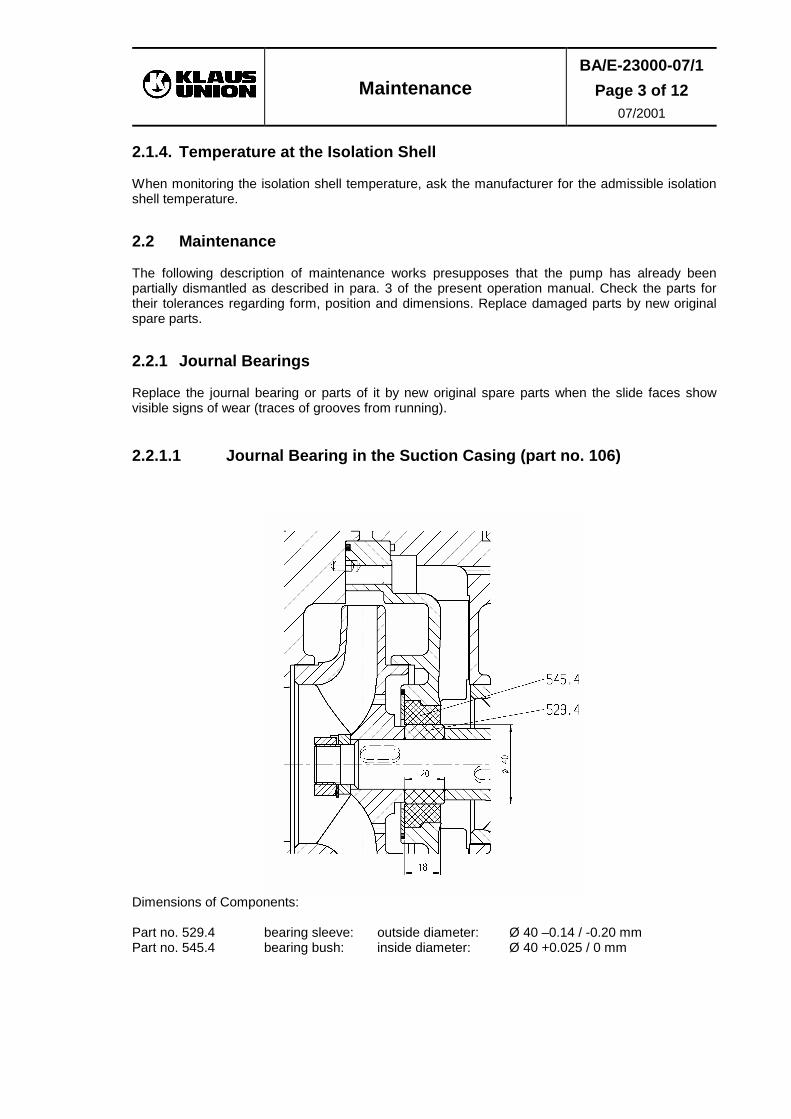
07/2001 2.1.4. Temperature at the Isolation Shell When monitoring the isolation shell temperature, ask the manufacturer for the admissible isolation shell temperature. 2.2 Maintenance The following description of maintenance works presupposes that the pump has already been partially dismantled as described in para. 3 of the present operation manual. Check the parts for their tolerances regarding form, position and dimensions. Replace damaged parts by new original spare parts. 2.2.1 Journal Bearings Replace the journal bearing or parts of it by new original spare parts when the slide faces show visible signs of wear (traces of grooves from running). 2.2.1.1 Journal Bearing in the Suction Casing (part no. 106)
Dimensions of Components: Part no. 529.4 bearing sleeve: outside diameter: Ø 40 –0.14 / -0.20 mm Part no. 545.4 bearing bush: inside diameter: Ø 40 +0.025 / 0 mm

Maintenance
BA/E-23000-07/1
Page 4 of 12
07/2001 2.2.1.2 Journal Bearing in the Pressure Casing (part no. 102)
Dimensions of Components: Part no. 529.1 bearing sleeve: outside diameter: Ø 53 –0.02 / -0.04 mm Part no. 545.1 bearing bush: inside diameter: Ø 53 +0.030 / 0 mm

Maintenance
BA/E-23000-07/1
Page 5 of 12
07/2001 2.2.2 Wear Ring Clearance Replace wear rings (part no. 512, 512.1) by new original spare parts when the following maximum radial clearances are exceeded:
Dimensions wear ring/impeller: Part no. Stage no. 1 Stages no. 2 - 6 Diffusor 170 Ø 100 +0.1 / 0 Ø 80 +0.1 / 0 Impeller 230 Ø 100 –0.3 / -0.35 Ø 80 –0.3 / -0.35 Total clearance
Min. 0.30 mm Min. 0.30 mm
Max. 0.45 mm Max. 0.45 mmMax. admissible clearance
Max. 0.80 mm Max. 0.80 mm

Maintenance
BA/E-23000-07/1
Page 6 of 12
07/2001 3. Dismantling 3.1 Preparations for the Disassembly of the Centrifugal Pump Execute the following works: • Interrupt the current feed to the motor. • Close the globe valves in suction and pressure pipings. • Dispose of the remaining residual liquid in the pump. • Remove the coupling guard. • Remove the motor from the base plate. • When using couplings with cartridge unit, only the cartridge unit needs to be disassembled; the
motor disassembly is not necessary. • Remove the pump-side coupling half from the drive shaft (part no. 213).
A T T E N T I O N
Use an offset cam for dismantling of the coupling.
• Disconnect suction and pressure nozzle from the piping. 3.2 Dismantling of the Centrifugal Pump Exclusively use the relevant sectional drawing of the pump for dismantling and re-assembly. Use the assembly aids referred to in para. 4 (Assembly Tools) for repair works Notice concerning dismantling of pump type SLM GVO (bearing support with oil-lubricated anti-friction bearings): Prior to dismantling, drain the oil from bearing support (part no. 330) by opening the oil drain plug (part no. 903.8) and dispose of the oil. Centrifugal pump type SLM GV is dismantled in vertical position. For dismantling purposes, the pump is screwed on an angle with the basis of the pressure casing (part no. 107) and the support (part no. 183). The suction casing (part no. 106) points upwards and is not screwed on the angle. The pump shaft pointed downwards must be supported with a wedge or a similar device after fastening the pressure casing. • Dismount the four retaining bolts (part no. 905) bracing the individual stages of the pump and
dismantle the suction casing (part no. 106). • Loosen the impeller nut (part no. 922): to do so, the suction impeller (part no. 230.1) needs to
be fixed by introducing a screwdriver from the outside into the channel between the impeller blades.

Maintenance
BA/E-23000-07/1
Page 7 of 12
07/2001 • Then the suction impeller can be pulled off the shaft. • Remove the first diffusor (part no. 170.1) together
with the integrated bearing bush (part no. 545.4) from the pump. Depending on the number of stages, dismantle the other diffusors (part no. 170.2), impellers (part no. 230.2) and multi-stage casings (part no. 108) as well as the pressure casing (part no. 107).
• To dismount the pressure casing, remove the eight
assembly stud nuts (part no. 920.1) located on the flange of the intermediate lantern (part no. 146.1). Subsequently release the basis of the pressure casing from the angle. The support of the intermediate lantern, however, remains screwed on the angle.
• Pull off the pressure casing. Afterwards, the final
impeller can be drawn off the shaft. • Subsequently, you can carefully dismount from the intermediate lantern the shaft together with
the casing cover (part no. 161) and the screwed-on isolation shell (part no. 817) for further dismantling.
• Then the bearing bracket composed of intermediate lantern (part no. 146.1) and bearing support (part no. 330) can then be released from the angle.
• For further dismantling of the journal bearing carefully fix the shaft in an assembly aid.
• Loosen and remove the cap screws (part no. 901.1) from the isolation shell flange and pull the
isolation shell (part no. 817) off the casing cover (part no. 161). • For dismantling of the inner magnet carrier (part no. 818.2) release the lock washer (part no.
931.2). Remove the shaft nut (part no. 921.2) together with the disk (part no. 504.4) and draw the complete inner magnet carrier off the pump shaft (part no. 211).
• Remove thrust bearing (part no. 314) from the shaft with care.

Maintenance
BA/E-23000-07/1
Page 8 of 12
07/2001 • Subsequently, it is possible to carefully remove the casing cover together with the screwed-on
journal bearing (part no. 545.4) and the wear ring (part no. 512.1) from the journal bearing sleeves (part no. 529.1).
• To completely dismantle the journal bearing bush (part no. 545.4), the hexagon socket screws (part no. 901.3) are to be removed. Afterwards it is possible to pull the journal bearing bush out of the casing cover.
3.2.1 Disassembly of Ball Bearings (Grease Lubrication / SLM GVS) As a precondition, the works described under para. 3.2 must have been carried out. • Loosen and remove the cap screws (part no. 901.17) from the bearing cover (part no. 360). • Remove the bearing cover (part no. 360) which is equipped with pulling-off bores (M6) for
dismantling. • Remove the snap ring (part no. 932). • Remove the complete bearing unit comprising drive shaft (part no. 213) with ball bearing (part
no. 321) and bearing insert (part no. 381) from the bearing bracket (part no. 331). • Dismantle the ball bearings (part no. 321) with standard offset cams. • Remove the bearing insert (part no. 381) from the drive shaft (part no. 213). 3.2.2 Disassembly of Ball Bearings (Oil Lubrication / SLM GVO) As a precondition, the works described under para. 3.2 must have been carried out. • Remove the thermal barrier (part no. 152) from the bearing support (part no. 330) and pull the
shaft sleeve (part no. 523) off the drive shaft. • Loosen and remove the cap screws (part no. 901.17). • Remove the bearing cover (part no. 360) which is equipped with pulling-off bores (M6) for
dismantling. • Remove the snap ring (part no. 932). • Remove the complete bearing unit comprising drive shaft (part no. 213) with ball bearing (part
no. 321) from the bearing bracket (part no. 331). • Remove the ball bearings (part no. 321) with standard offset cams. 4. Assembly Tools
Designation Id.-No. Clamping Device for Magnet Carrier Size 130 1045
5. Re-Assembly • Check the usability all pump components prior to re-assembly. • Protect the anti-friction bearings from dirt and moisture. • Tighten the screws according to the tightening moments given under para. 5.4. • Clean all tight and bearing surfaces and replace used gaskets by new ones.

Maintenance
BA/E-23000-07/1
Page 9 of 12
07/2001 5.1 Assembly of Ball Bearings (Grease Lubrication / SLM GVS)
• Warm up the ball bearings (part no. 321) to approx. 80 °C in the usual ways (oil bath, heating plate, inductive).
• Push the front ball bearing (part no. 321) onto the drive shaft (part no. 213). • Push the bearing insert (part no. 381) onto the drive shaft (part no. 213). • Push the back ball bearing (part no. 321) previously warmed up to 80 °C onto the drive shaft
(part no. 213). • For assembly of the complete bearing unit, warm up the bearing support (part no. 330) in the
bearing seat area to approx. 80 °C in the usual ways (oil bath, inductive). • Insert the snap ring (part no. 932) into the bearing support and push the complete bearing unit
into the bearing support. • Insert the radial shaft seal ring (part no. 421.2) into the bearing cover (part no. 360) and mount
the bearing cover (part no. 360). • Grease the ball bearings (part no. 321) via the grease nipple (part no. 630.2). 5.2 Assembly of Ball Bearings (Oil Lubrication / SLM GVO)
• Warm up the ball bearings (part no. 321) to approx. 80 °C in the usual ways (oil bath, heating plate, inductive).
• Push both ball bearings (part no. 321) onto the drive shaft (part no. 213). • For assembly of the complete bearing unit, warm up the bearing support (part no. 330) in the
bearing seat area to approx. 80 °C in the usual ways (oil bath, inductive). • Insert the snap ring (part no. 932) into the bearing support and push the complete bearing unit
into the bearing support).

Maintenance
BA/E-23000-07/1
Page 10 of 12
07/2001 • Insert the radial shaft seal ring (part no. 421.2) in the bearing cover (part no. 360) and mount the
bearing cover (part no. 360). • Push the distance sleeve(part no. 525.1) onto the drive shaft.
Insert the secondary sealing (part no. 421.3) in the thermal barrier (part no. 152) observing the correct assembly direction: The chamber to be sealed is the outer magnet carrier chamber!
• The sealing faces of the thermal barrier facing the bearing support and the intermediate
lantern are to be coated with a liquid sealant. Centre the thermal barrier in the bearing support making sure that the through holes (for the forcing screws) in the thermal barrier are precisely aligned with the forcing threads in the bearing support.
5.3 Assembly of the Complete Pump The following assembly procedure assumes that the bearings have already been fitted in accordance with para. 5.1 or 5.2. • Secure drive shaft (part no. 213) against turning (use mechanical aid). • Insert key (part no. 940.1) into key groove of the drive shaft (part no. 213).
When using spare parts to replace an outer magnet carrier tube and / or an outer magnet carrier hub, the resulting assembly must be balanced again. For this purpose mount the outer magnet carrier tube (part no. 818.1) on the outer magnet carrier hub (part no. 861) with the help of the hexagon socket screws (part no. 914.10) and balance this unit to DIN ISO 1940 – quality class G 6.3
• Mount the complete outer magnet carrier on the drive shaft (part no. 213). Install the lock washer (part no. 931) and the shaft nut (part no. 921) on the drive shaft and tighten the shaft nut.
Then the intermediate lantern (part no. 146.1) can be screwed down together with the bearing support (part no. 330).
Lagerbock SLM GVS
Maintenance
BA/E-23000-07/1
Page 11 of 12
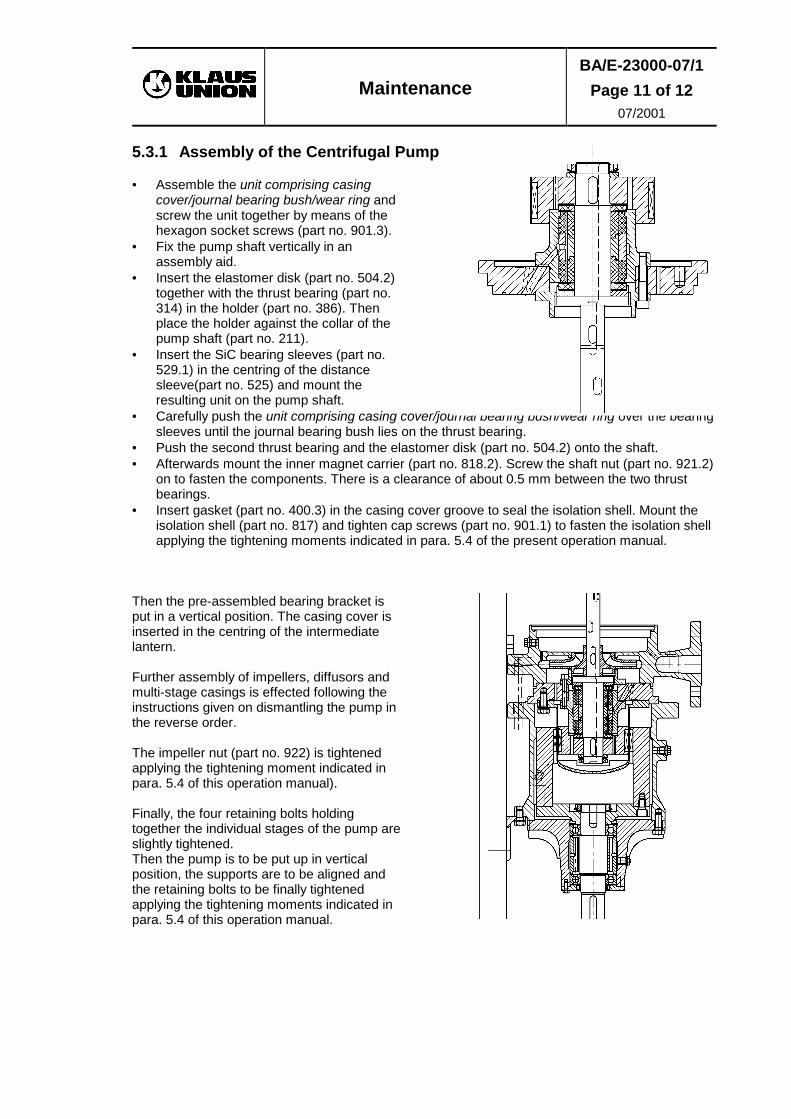
07/2001 5.3.1 Assembly of the Centrifugal Pump • Assemble the unit comprising casing
cover/journal bearing bush/wear ring and screw the unit together by means of the hexagon socket screws (part no. 901.3).
• Fix the pump shaft vertically in an assembly aid.
• Insert the elastomer disk (part no. 504.2) together with the thrust bearing (part no. 314) in the holder (part no. 386). Then place the holder against the collar of the pump shaft (part no. 211).
• Insert the SiC bearing sleeves (part no. 529.1) in the centring of the distance sleeve(part no. 525) and mount the resulting unit on the pump shaft.
• Carefully push the unit comprising casing cover/journal bearing bush/wear ring over the bearing sleeves until the journal bearing bush lies on the thrust bearing.
• Push the second thrust bearing and the elastomer disk (part no. 504.2) onto the shaft. • Afterwards mount the inner magnet carrier (part no. 818.2). Screw the shaft nut (part no. 921.2)
on to fasten the components. There is a clearance of about 0.5 mm between the two thrust bearings.
• Insert gasket (part no. 400.3) in the casing cover groove to seal the isolation shell. Mount the isolation shell (part no. 817) and tighten cap screws (part no. 901.1) to fasten the isolation shell applying the tightening moments indicated in para. 5.4 of the present operation manual.
Then the pre-assembled bearing bracket is put in a vertical position. The casing cover is inserted in the centring of the intermediate lantern. Further assembly of impellers, diffusors and multi-stage casings is effected following the instructions given on dismantling the pump in the reverse order. The impeller nut (part no. 922) is tightened applying the tightening moment indicated in para. 5.4 of this operation manual). Finally, the four retaining bolts holding together the individual stages of the pump are slightly tightened. Then the pump is to be put up in vertical position, the supports are to be aligned and the retaining bolts to be finally tightened applying the tightening moments indicated in para. 5.4 of this operation manual.

Maintenance
BA/E-23000-07/1
Page 12 of 12
07/2001 5.4 Tightening Moments for Screws
Part no. Location of Screws
Material of Screws
Thread Tightening Moment [Nm]
901.1 Isolation shell A4-70 M10 / M12
40 / 65
1.7258 1.7709 45 / 75 905 Retaining bolt 1.7258 M20 100 920.1 Intermediate
lantern 5.6 M16 80
A4-70 1.7258 90 1.7709 922 Impeller nut 1.4571 M20x1 110
6. Spare Parts The attached spare parts list enumerates the recommended spare parts.

Malfunctions; Causes & Elimination
BA/E-01000-08/0
Page 1 of 3
C o n t e n t s P a g e 1. Malfunctions and Causes 1 2. Causes and Proceedings for Elimination of Malfunctions 2
1. Malfunctions and Causes
No./Malfunction
Ref.-No. for Cause and Elimination
1/Flow is too low 1, 8, 9, 12, 14, 15
2/Flow is too high 2, 16
3/Delivery head is too low 2, 3, 8, 9, 10, 11, 12, 15
4/Delivery head is too high 1, 16, 32, 33
5/Pump does not suck or only to a
limited extent
3, 5, 8, 15
6/Pump does not feed 3, 4, 5, 6, 8, 15,
7/Pump processes by fits and starts 3, 5, 8
8/Pump operates noisily 3, 5, 6, 7, 12, 13
9/Power consumption is too high 2, 6, 7, 10, 11, 13,16
10/Power consumption is too low 9, 15, 32, 33
11/Pump runs backwards 12, 18
12/Pump runs unsteadily 7, 13, 17, 19, 20, 21, 22, 23, 24, 25, 26, 27, 28, 29
13/Pump casing leaks 28, 30, 31
14/Pump is running hot 4, 15, 17
15/Pump stalled 6, 7, 13

Malfunctions; Causes & Elimination
BA/E-01000-08/0
Page 2 of 3
2. Causes and Proceedings for Elimination of Malfunctions
Ref.-No.:
Cause
Elimination
1
Piping resistance in pressure piping is too high.
Clean or replace the pipings and/or the valves. Check the dimensioning of the pipings' nominal diameter.
2
Pressure-side piping resistance is too low.
Throttle the pressure-side control valve.
3
Feed pressure is too low. Geodetic suction height is too high.
Increase the feed pressure on the feed-side.
4
Shut-off valve in the pressure-side and suction-side piping respectively is closed.
Open the shut-off valve. Check whether swing check valve opens.
5
The suction-side piping still contains gas bubbles.
Vent the unit and check the laying of the pipings.
6
Foreign matters in the pump.
Disassemble the pump and remove the foreign matters. Replace damaged parts by new original spare parts.
7
Wear of slide bearings.
Check the bearing clearance.
8
Suction piping leaks.
Check the suction-side piping connections and tightening moments of screws. Check the suction-side gaskets. Check the tightening moments of screws at the spiral casing. Check the gaskets at the spiral casing. Replace damaged gaskets by new original spare parts.
9
Speed is too low.
Check the frequency and the voltage.
10
Viscosity of liquid is too high.
Contact the manufacturer.
11
Viscosity and density of the liquid are too high.
Contact the manufacturer.
12
Wrong direction of rotation.
Reconnect the power lead at the motor according to the direction-of-rotation arrow.
13
Damaged roller bearings.
Replace the roller bearings. Clean the oil chamber in the bearing bracket. Check whether the lubricant is suitable for your field of application.
14
Inadmissible reduction of area of cross section in the suction piping.
Clean suction-side filters. Remove precipitations in the suction piping or replace the suction piping.
15
Breakaway of magnet drive.
Switch off the motor and wait until it stands still. Switch the motor on again. Contact the manufacturer.

Malfunctions; Causes & Elimination
BA/E-01000-08/0
Page 3 of 3
Ref.-No.:
Cause
Elimination
16
Speed is too high.
Check the frequency and the voltage of the motor.
17
Flush flow is too low.
Clean the flush flow filter. Check the flushing system. Check whether you fall short of the minimum quantity Qmin.
18
Swing check valve got stuck.
Check the operativeness of your swing check valve.
19
The impeller is clogged or damaged.
Clean the impeller and replace it by a new original spare part respectively.
20
Precipitation of crystals from the liquid.
Increase the temperature of the liquid, e. g. by heating the pump. Contact the manufacturer.
21
Specified quantity of lubricant was not observed.
Check the roller bearings for their suitability (if necessary, replace them by new original spare parts) and increase the quantity of the lubricant according to the specification.
22
Unsuitable lubricant.
Check the roller bearings for their suitability (if necessary, replace them by new original spare parts) and check whether the lubricant is suitable for your field of application.
23
Inexpert assembly of roller bearings.
Check the roller bearings for their suitability (if necessary, replace them by new original spare parts) and assemble them properly.
24
Misaligned or loose coupling.
Check and correct the alignment of your coupling. Tighten the connecting bolts.
25
Elastic coupling elements are worn off.
Replace the elastic coupling elements.
26
Poor workmanship of the foundation.
Check and correct the construction of your foundation.
27
Base plate not rigid enough with foundationless execution.
Contact the manufacturer.
28
Pump casing is distorted.
Check and correct the piping lengths.
29
Pump design is wrong.
Contact the manufacturer.
30
Unsuitable casing gasket.
Replace the casing gasket by a new original gasket.
31
Casing screws have been tightened insufficiently.
Tighten the casing screws according to the specified tightening moments.
32
Density of liquid is too low.
Contact the manufacturer.
33
Viscosity and density of the liquid are too low.
Contact the manufacturer.