Centre for Cement and Concrete Applications of FRP/GRC in...
15
Centre for Cement and Concrete Applications of FRP/GRC in Permanent Formwork Mr. G.B.KIM, Prof. P. WALDRON, Prof. K. Pilakoutas (Centre of Cement and Concrete, The University of Sheffield, UK) Presented by: G.B.KIM Innovative Innovative Materials Materials and and Technologies Technologies for for Construction Construction and and Restoration Restoration Lecce Lecce (Italy), June 6 (Italy), June 6 - - 9, 2004 9, 2004
Transcript of Centre for Cement and Concrete Applications of FRP/GRC in...

Centre forCement and Concrete
Applications of FRP/GRC in Permanent Formwork
Mr. G.B.KIM, Prof. P. WALDRON, Prof. K. Pilakoutas(Centre of Cement and Concrete, The University of Sheffield, UK)
Presented by: G.B.KIM
InnovativeInnovative MaterialsMaterials andand Technologies Technologies forfor ConstructionConstruction andand RestorationRestorationLecceLecce (Italy), June 6(Italy), June 6--9, 20049, 2004
Centre forCement and Concrete
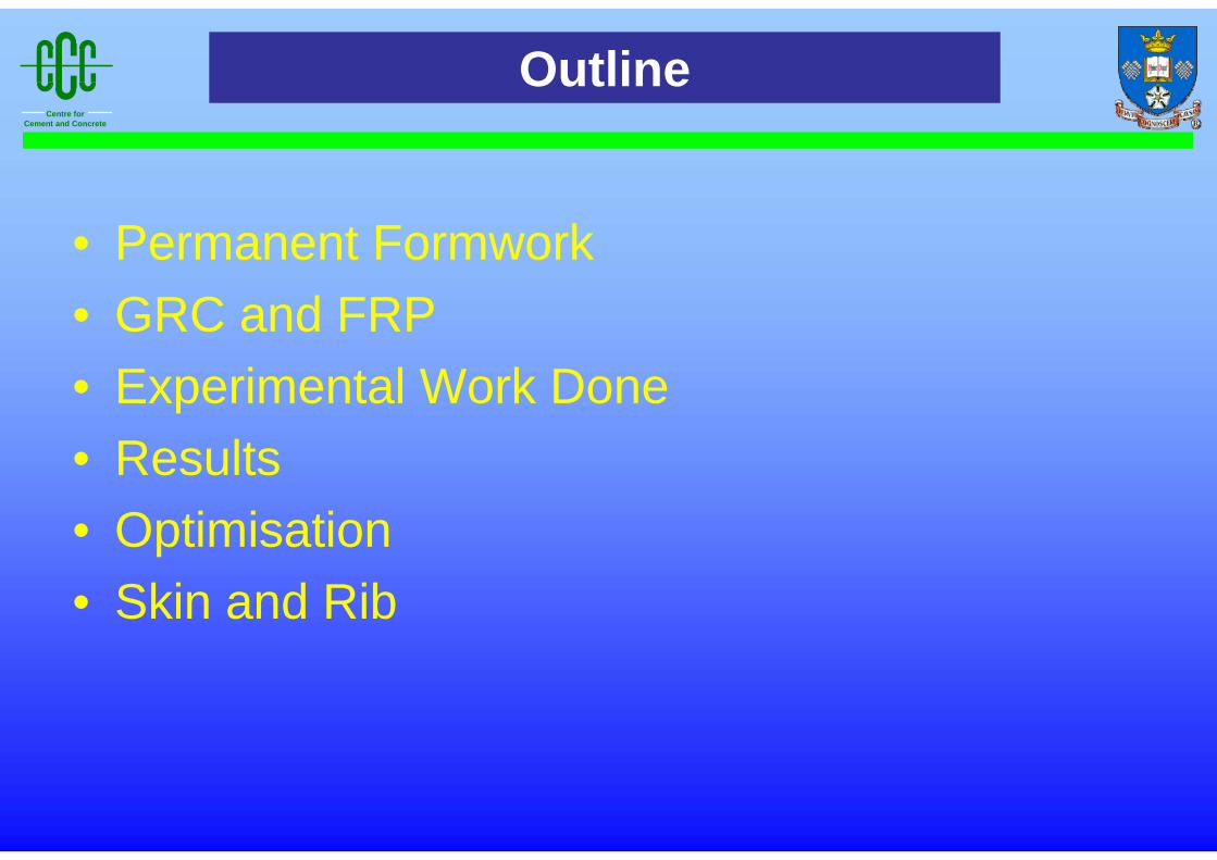
• Permanent Formwork• GRC and FRP• Experimental Work Done• Results• Optimisation• Skin and Rib
Outline
Centre forCement and Concrete
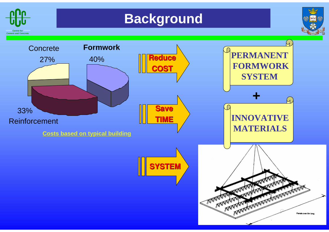
PERMANENTFORMWORK
SYSTEM
SaveSave
TIMETIME
Formwork40%
Reinforcement33%
Concrete27%
Costs based on typical building
ReduceReduce
COSTCOST
SYSTEMSYSTEM
INNOVATIVEMATERIALS
Background
+

Centre forCement and Concrete
Permanent Formwork Systems
Steel decking
Speed & Simplicity
CorrosionFire protection
Constant thicknessOne way spanning
Need additional finishes
Pre-cast concrete
Attractive finish
Heavy handling
GRC
LightAttractive finish
Any shape
Low strength Short spans
Omni-plank type
Effective load transferSpeedy construction
Controlled finish
Crack in tension zone during casting
Centre forCement and Concrete
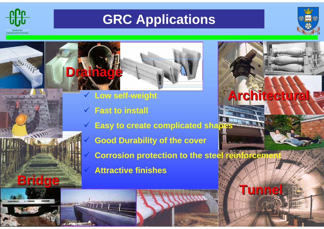
GRC Applications
DrainageDrainage
TunnelTunnel
ArchitecturalArchitectural
BridgeBridge
Low self-weight
Fast to install
Easy to create complicated shapes
Good Durability of the cover
Corrosion protection to the steel reinforcement
Attractive finishes

Centre forCement and Concrete
• Strength/Specific Gravity (10-15 times that of steel)
• Corrosion Resistance
• Fatigue Characteristics
• Electromagnetic Neutrality
• Require minimum cover
• High Cost
• Low Elastic Modulus
• Stress Corrosion
• Lack of Ductility
• Anisotropic properties
1 00 0
2 00 0
%
σ
ε
(M P a )
0 1 2 3
R e inf orc ing S te e l
P re s tre ss ing S te e l
A F R P
G F R P
C F R P
FRP PROs & CONs
Centre forCement and Concrete
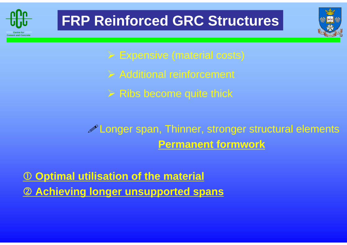
Expensive (material costs)
Additional reinforcement
Ribs become quite thick
Longer span, Thinner, stronger structural elementsPermanent formwork
Optimal utilisation of the materialAchieving longer unsupported spans
FRP Reinforced GRC Structures
Centre forCement and Concrete
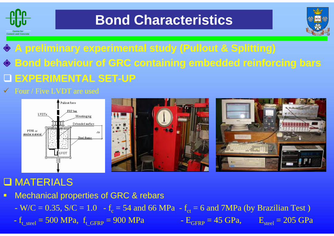
A preliminary experimental study (Pullout & Splitting)Bond behaviour of GRC containing embedded reinforcing bars
Bond Characteristics
EXPERIMENTAL SET-UPFour / Five LVDT are used
MATERIALSMechanical properties of GRC & rebars- W/C = 0.35, S/C = 1.0 - fc = 54 and 66 MPa - fct = 6 and 7MPa (by Brazilian Test ) - ft_steel = 500 MPa, ft_GFRP = 900 MPa - EGFRP = 45 GPa, Esteel = 205 GPa

Centre forCement and Concrete
SLIPActual slip of the bar with respect to the concrete, δle
Average slip measurements of three LVDTs, δav
Elastic elongation of the unbonded portion of the bar, Δl
BOND STRESS
where, δ1 , δ2 , δ3 = slip measurements of the three LVDTs
la = unloaded length
F = applied pullout load
E = elastic modulus of the bar
A = cross-sectional area of the bar
where, F = applied pullout load
d = diameter
L = bond length of the bar
Analysis of Results
( ) )/(3/321 EAFll aavle −++=Δ−= δδδδδ
dLFπ
τ =

Centre forCement and Concrete
0
2
4
6
8
10
12
14
0 2 4 6 8 10
Slip (mm)
Bon
d S
tress
(MP
a)
loaded end (GRC)loaded end(Concrete)
Similar failure mechanismGRC provides higher initial and residual strength than ConcreteBond stress in GRC ; 60% (pullout) & 26% (splitting) higher than in Concrete
<Bond Stress - Slip curves ; 8mm GFRP bars>
0
1
2
3
4
-3 -2 -1 0 1 2 3 4 5 6 7 8
Crack Width (mm) Slip (mm)
Bon
d S
tress
(MP
a)
loaded end(GRC)crack(GRC)loaded(Concrete)crack(Concrete)
GRC & Concrete

Centre forCement and Concrete
Ct/2Ct/2
Bt=R
At
θ
At
t
Optimisation
f
H
At
Dt
Bt
Ct/2 BtCOSθ
θ
BtCOSθ Ct/2
t
∆Uθ1
θ4
l
θ3θ2
x
y
[ ]6sin1sin
26
2342
44 θθ BtBAtAtI +−+=
[ ] θθθθ cossin6sin1sin
26243
2342
44
tBBtBAtAtI ++−+=
∑=
Δ=m
nxnx II
1
( ) ( ) 223
sin12
yutut
I cnc
xn Δ+Δ
=Δ θ 21++
= nn yyy
Trapezoidal section
Re-entrant section
Sinusoidal section
( )( )θ
ρcosBA
tBAWua ++
=
where, where, At is the width of the top plate, θ is the inclination of the sloping plate, Wua is the weight of material per unit area,
Z’w is section modulus per unit weight, ρ is the density, ym is distance from bottom fibre to neutral axis of section,
t is the thickness, m is the total number of segments, Δu is the constant segment length,
and ΔIxn is the moment of inertia of a segment above the centroidal axis.
( )ua
mw W
yIZ /' =

Centre forCement and Concrete
6.0E+05
8.0E+05
1.0E+06
1.2E+06
1.4E+06
1.0 2.0 3.0 4.0
R
I' m (m
m4 /m
)
2.0E+04
2.5E+04
3.0E+04
3.5E+04
4.0E+04
4.5E+04
Z'w
(mm
4 / m
m2 )
I’m
Z’w
Relationship of profile variables
R = Inclined chord / Top chord , K = Bottom chord / Top chord
I & Wua↗ with θ
for a constant depth and when K = 1, θdecreases as R increases
Trapezoidal section (per metre width);
I’m↗ with R, but Z’w↙
Controlling factor = δ, θ=90, but buckling, R=1.51
When θ=90 & constant depth, K=1.6~1.7
K=0.2 & K’=0.2 ; (exactly same I)
construction stage(K=0.2)
composite stage (K’=0.2)
1000
1200
1400
1600
1800
2000
0.0 1.0 2.0 3.0 4.0 5.0K & K'
Z'w(m
m4 /m
m2 )
K=C/A
K'=1/KK’ ≅ 0.6 K ≅ 1.6~1.7
K=0.2 K'=0.2
Centre forCement and Concrete
Optimum angle & Cross section
Trapezoidal section
0
5000
10000
15000
20000
25000
30000
35000
40000
10 20 30 40 50 60 70 80 90Degrees
Z'w
(mm
4 /mm
2 )
R=1
R=2
R=350°
55°
65°
Re-entraint section
0
20000
40000
60000
80000
100000
120000
10 20 30 40 50 60 70 80 90Degrees
Z'w
(mm
4 /mm
2 )
50°
45°
40°
R=3
R=2
R=1
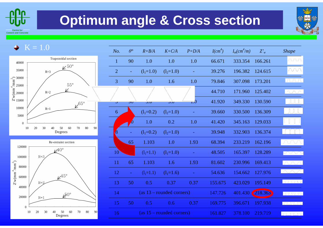
No. θ° R=B/A K=C/A P=D/A I(cm4) Im(cm4/m) Z’w Shape
1 90 1.0 1.0 1.0 66.671 333.354 166.261
2 - (l1=1.0) (l2=1.0) - 39.276 196.382 124.615
3 90 1.0 1.6 1.0 79.846 307.098 173.201
4 - (l1=1.0) (l2=1.6) 44.710 171.960 125.402
5 90 5.0 5.0 1.0 41.920 349.330 130.590
6 - (l1=0.2) (l2=1.0) - 39.660 330.500 136.309
7 90 1.0 0.2 1.0 41.420 345.163 129.033
8 - (l1=0.2) (l2=1.0) - 39.948 332.903 136.374
9 65 1.103 1.0 1.93 68.394 233.219 162.196
10 - (l1=1.1) (l1=1.0) - 48.505 165.397 128.289
11 65 1.103 1.6 1.93 81.602 230.996 169.413
12 - (l1=1.1) (l1=1.6) - 54.636 154.662 127.976
13 50 0.5 0.37 0.37 155.675 423.029 195.149
14 (as 13 – rounded corners) 147.726 401.430 218.363
15 50 0.5 0.6 0.37 169.775 396.671 197.938
16 (as 15 – rounded corners) 161.827 378.100 219.719
K = 1.0
Centre forCement and Concrete
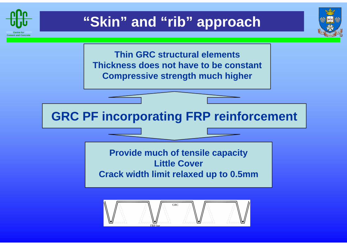
FRP bar
GRC
“Skin” and “rib” approach
GRC PF incorporating FRP reinforcement
Thin GRC structural elementsThickness does not have to be constant
Compressive strength much higher
Provide much of tensile capacityLittle Cover
Crack width limit relaxed up to 0.5mm
Centre forCement and Concrete
• Combination of new materials (superior durability)
• Bond Strength Good(τ FRP rebar and GRC ≈ 1.6 × τ FRP rebar and concrete )
• Development of integrated permanent formwork solutions
• Develop ; connection, support system & further study ; load-carrying capacity of completed slab
• Case studies
• Design guidelines
Conclusions