Centre de rencontre de Cartigny D. Ferrère, 11 June 2008 On behalf of the University of Geneva.
43
ATLAS Upgrade ATLAS Upgrade Centre de rencontre de Cartigny D. Ferrère, 11 June 2008 On behalf of the University of Geneva
-
date post
18-Dec-2015 -
Category
Documents
-
view
214 -
download
1
Transcript of Centre de rencontre de Cartigny D. Ferrère, 11 June 2008 On behalf of the University of Geneva.
ATLAS UpgradeATLAS Upgrade
Centre de rencontre de CartignyD. Ferrère, 11 June 2008
On behalf of the University of Geneva

Possible Machine ScenariosPossible Machine Scenarios
3 phases considered:
Phase 0: Push the machine to its maximum performance without hardware changeLuminosity of 3x1034 cm-2s-1. and ultimate energy 7.54 TeV (dipole field @ 9T)
Phase 1 (SLHC): Interaction Region (IR) quadrupoles life expectancy < 10 years Modify the insertion quadrupoles and their layout *
Phase 2: Rebuild the SPS with superconducting magnets, the transfer line to inject into LHC at 1 TeV and new 15T dipoles proton energy of 12.5 TeV
ParametersLHC SLHC - Phase1
Nominal Ultimate Scenario 1 Scenario 2
Bunch spacing [ns] 25 25 50 25
Proton/bunch Nb[1011] 1.15 1.7 4.9 1.7
* at IP1&5 [m] 0.55 0.5 0.25 0.08
Longitudinal profile Gaussian Gaussian Flat Gaussian
Rms bunch length z[cm] 7.55 7.55 11.8 7.55
Peak luminosity [1034 cm-2s-1] 1 2-3 10.7 15.5
Effective luminosity (5h) [1034 cm-2s-1] 0.56 1.15 3.5 3.6
Peak events per crossing 19 44 403 294
CommentsWire comp. Crab + D0
(+ Q0)
NB: Original scenario of 12.5 ns excluded since exceed the max local cooling capacity
Ba
se
lin
e
Alt
ern
ati
ve
Far future
Cartigny, June 11th 2008 ATLAS Upgrade, Didier 2
20
14
-15
20
11
-12
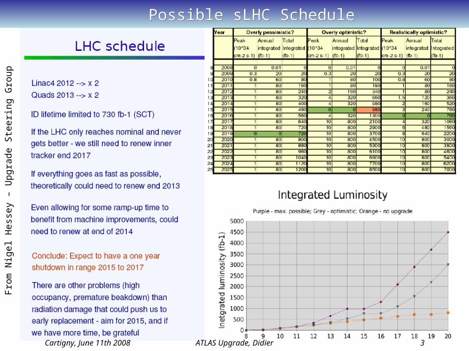
Possible sLHC SchedulePossible sLHC Schedule
Cartigny, June 11th 2008 ATLAS Upgrade, Didier 3
Fro
m N
igel
Hes
sey
– U
pgr
ade
Ste
erin
g G
roup

Rough ATLAS Upgrade ScheduleRough ATLAS Upgrade Schedule
Cartigny, June 11th 2008 ATLAS Upgrade, Didier 4
Other factors:• CMS do not believe they can upgrade their inner tracker to run before 2018 • LHC expects new injectors (new PS replacement) ready for full sLHC in 2017 (so no data in 2016 would get us ready in time)• ATLAS could need to install in 2015 if LHC starts up fast and reaches “Ultimate” 2-3.1034
• Clearly we should only have one major shutdown• Propose discussion within LHCC to agree which year is the major shutdown
Very rough outline for ID Upgrade:• Start 2007: 3 years R&D 2007-2009• TDR April 2010• Other documents 2010; design work; final prototypes• PRR's, start procurement 2011• 2 years building modules (and continuous parts procurement) 2012-2013• Surface assembly and test 2013-2014• Stop LHC end 2014• Install 2015• Take data April 2016

ATLAS Upgrade - DetectorATLAS Upgrade - Detector
Cartigny, June 11th 2008 ATLAS Upgrade, Didier 5
Due to increase of radiation level, pile-up, background Due to increase of radiation level, pile-up, background each sub-detectors has to think of the consequences in each sub-detectors has to think of the consequences in term of detector performance, aging, radiation hardness!term of detector performance, aging, radiation hardness!
Inner Detector (ID):Completely new design and detectors – No TRT, more pixel and strips: New detector and ASICs technologies to withstand the radiation level Simulations drive optimal geometry (Strawman layers) and occupancies
LAr Calorimeter:FCAL: To be replaced with smaller gap size and special cooling close to the beam pipe.HEC: Cold electronics may have to be replaced (no need to get HEC wheels apart)Others: More R&D require about the Ion buid-up
Tile Calorimeter:Front-end electronics and Low Voltage Power Supplies
Muon System:MDT: Chambers and readout electronics are radhard at LHC or can stand 10 times the max nominal flux but further studies need to be performed in SLHC environment
2008: detail upgrade plan based on some tests and R&DTGC: Thick GEMs or MM can possibly replace forward chambers due to high occupancy.
Focus
Cartigny, June 11th 2008 ATLAS Upgrade, Didier 6
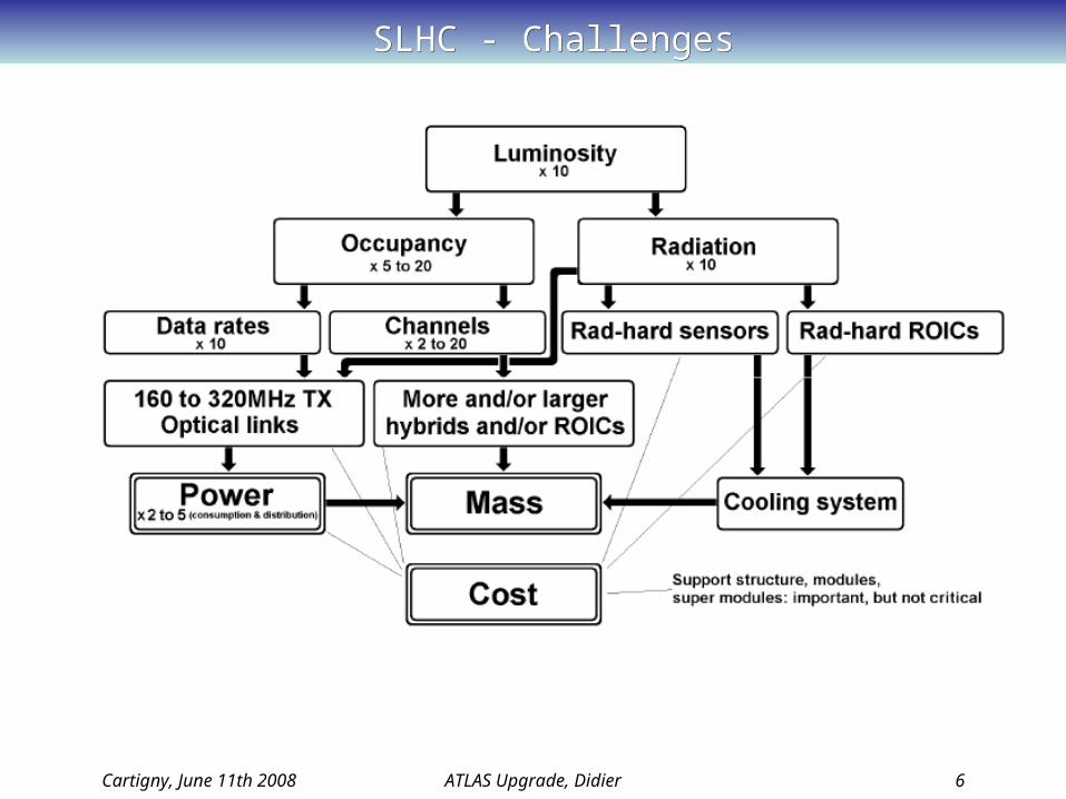
SLHC - ChallengesSLHC - Challenges

ATLAS Upgrade – OrganizationATLAS Upgrade – Organization
Cartigny, June 11th 2008 ATLAS Upgrade, Didier 7
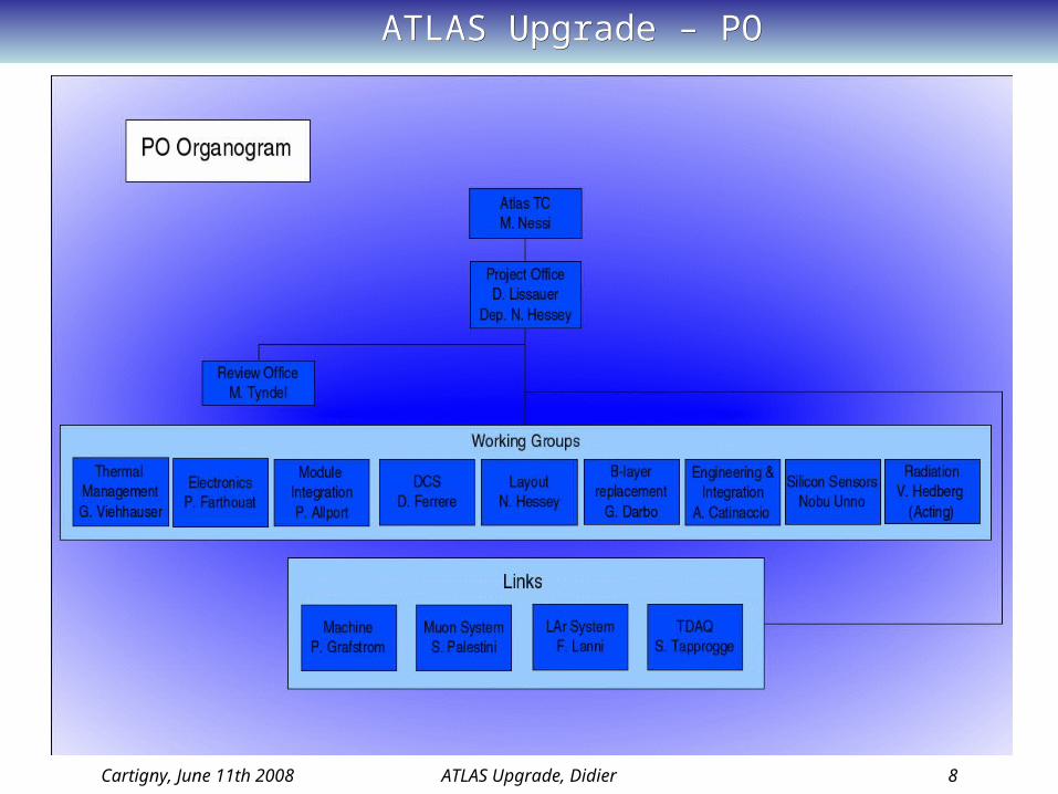
ATLAS Upgrade – POATLAS Upgrade – PO
Cartigny, June 11th 2008 ATLAS Upgrade, Didier 8
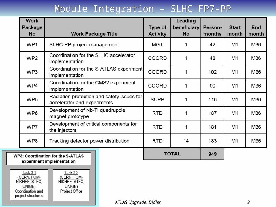
Module Integration – SLHC FP7-PPModule Integration – SLHC FP7-PP
Cartigny, June 11th 2008 ATLAS Upgrade, Didier 9
Cartigny, June 11th 2008 ATLAS Upgrade, Didier 10
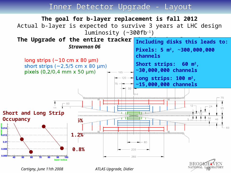
Inner Detector Upgrade - LayoutInner Detector Upgrade - Layout
The goal for b-layer replacement is fall 2012Actual b-layer is expected to survive 3 years at LHC design luminosity
(~300fb-1)The Upgrade of the entire tracker should take place in 2016
Strawman 06Including disks this leads to:
Pixels: 5 m2, ~300,000,000 channels
Short strips: 60 m2, ~30,000,000 channels
Long strips: 100 m2, ~15,000,000 channels
1.6%
1.2%
Short and Long Strip Occupancy
0.8%
Cartigny, June 11th 2008 ATLAS Upgrade, Didier 11
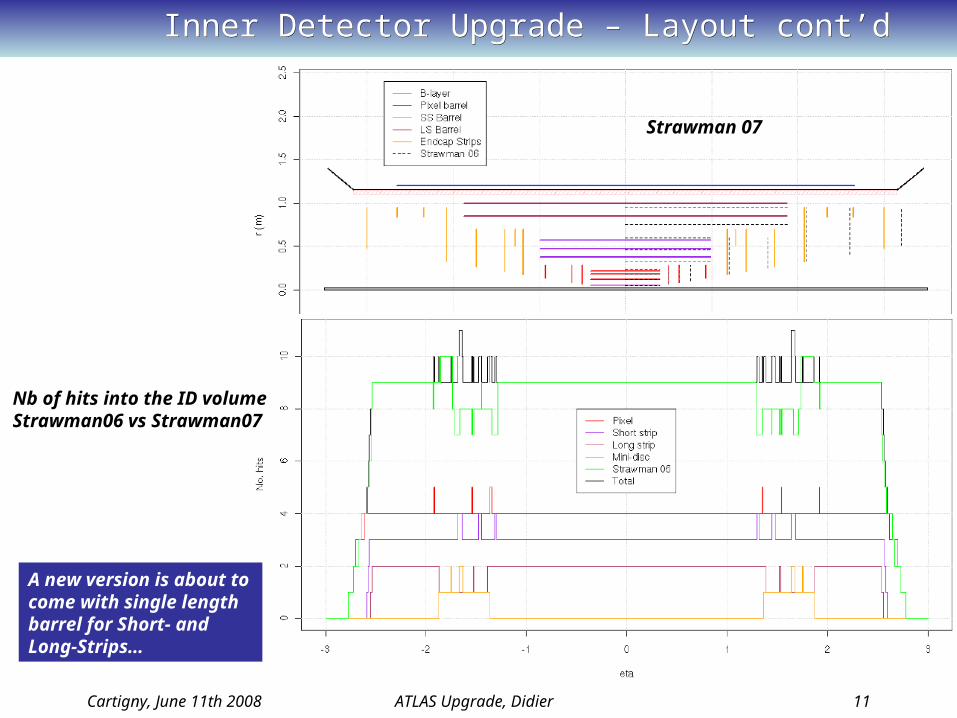
Inner Detector Upgrade – Layout cont’dInner Detector Upgrade – Layout cont’d
Strawman 07
Nb of hits into the ID volumeStrawman06 vs Strawman07
A new version is about to come with single length barrel for Short- and Long-Strips…
Cartigny, June 11th 2008 ATLAS Upgrade, Didier 12
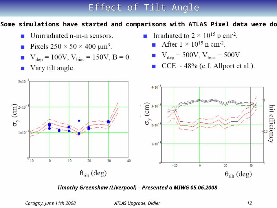
Effect of Tilt AngleEffect of Tilt Angle
Timothy Greenshaw (Liverpool) – Presented a MIWG 05.06.2008
Some simulations have started and comparisons with ATLAS Pixel data were done
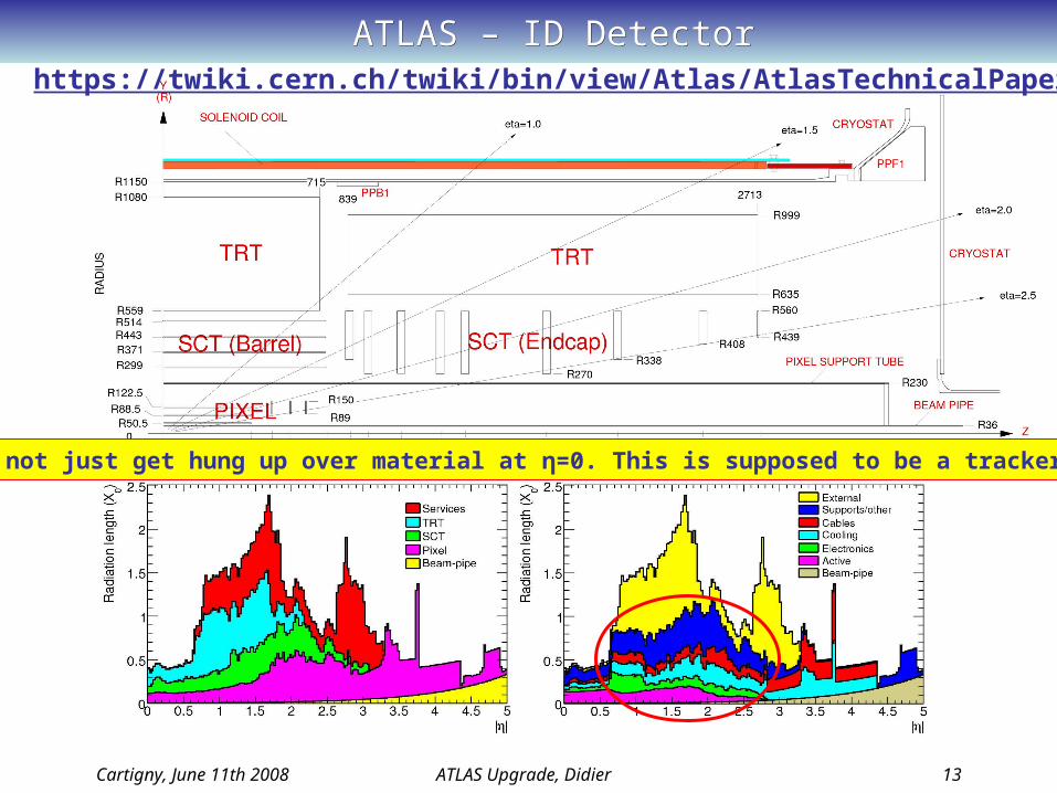
ATLAS – ID DetectorATLAS – ID Detector
Cartigny, June 11th 2008 ATLAS Upgrade, Didier 13
https://twiki.cern.ch/twiki/bin/view/Atlas/AtlasTechnicalPaper
Next time, lets not just get hung up over material at η=0. This is supposed to be a tracker up to |η|≤2.5

Cartigny, June 11th 2008 ATLAS Upgrade, Didier 14
ATLAS - SCTATLAS - SCT
A piece of art in term of services and engineering!
Barrel modules were mounted with a robot not the endcap!

Cartigny, June 11th 2008 ATLAS Upgrade, Didier 15
Radiation Background in ATLAS at SLHCRadiation Background in ATLAS at SLHC
1 MeV equivalent neutron fluences assuming an integrated luminosity of 3000fb-1 and 5cm of moderator lining the calorimeters (reduces fluences by ~25%)
•With safety factor of two, design short microstrip layers to withstand 1015neq/cm2 (50% neutrons)
•Outer layers up to 4×10¹⁴neq/cm2 (and mostly neutrons)
Thermal management and shot noise. Silicon looks to need to be at ~ -25oC (Thermal runaway).Si power: 1W @ -20°C
4W @ -10°C10W @ 0°C
High levels of activation will require careful consideration for access and maintenance.
IssuesIssues
Simulation using FLUKA2006

Cartigny, June 11th 2008 ATLAS Upgrade, Didier 16
Silicon Sensors Technology versus RadiationSilicon Sensors Technology versus Radiation
Choice of adequate material thanks to RD50 collaboration
Pixel and Strips: n-in-p (planar technology)
No type inversion, full depletion is on structured side
Collection of electrons (faster than p-in-n)
0 20 40 60 80 100 120eq [1014 cm-2]
0
5000
10000
15000
20000
25000
sign
al [e
lect
rons
]
3D FZ Si, 235 m, (laser injection, scaled!), pad [Da Via 2006]n-FZ Si, 280 m, (-10oC, 40ns), n-in-n pixel [Rohe et al. 2005]p-FZ Si, 280 m, (-30oC, 25ns), strip [Casse 2004]p-MCZ Si, 300 m, (-30oC, s), pad [Bruzzi 2006]n-epi Si, 150 m, (-30oC, 25ns), pad [Kramberger 2006]n-epi Si, 75 m, (-30oC, 25ns), pad [Kramberger 2006]sCVD-Diamond, 770m, (RT, s), [RD42 2006] (preliminary data, scaled)pCVD-Diamond, 500m, (RT, s), strip, [RD42 2002-2006] (scaled)SiC, n-type, 55 m, (RT, 2.5s), pad [Moscatelli et al. 2006]
M.Moll 2007
Pixel b-layer: 3D technology is an option(should be ready for b-layer replacement in 20012)
electrons swept away by transversal field holes drift in
central region and diffuse towards p+
contact
Exist in single and double column type
n+-columns
ionizing particle
p-Si
3D FZ 235m
P-FZ 280m
Still ~15000e- at 1.1015 cm-2s-1 (FZ or MCZ)

Cartigny, June 11th 2008 ATLAS Upgrade, Didier 17
Short Strip Sensors - HPKShort Strip Sensors - HPK
9.75cm
9.75
cm
• Dimension– Full square
• Wafer– 150 mm p-type
FZ(100)– 138 mm dia. usable– 320 µm thick
• Axial strips– 74.5 µm pitch
• Stereo strips– 40 mrad– 71.5 µm pitch
• Bond pads location– accommodating 24-
40 mm distances• n-strip isolation
– P-stop– Spray on
miniatures Y. Unno
•Strip segments– 4 rows of 2.38 cm strips (each row
1280 channels)
130 detectors ordered end of last year (15 for UniGe)!

Cartigny, June 11th 2008 ATLAS Upgrade, Didier 18
First Engineering LayoutFirst Engineering Layout
Knowing the detector size and module and the layout…
Cartigny, June 11th 2008 ATLAS Upgrade, Didier 19
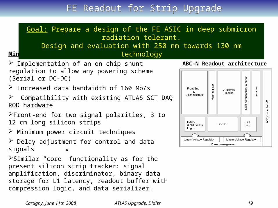
FE Readout for Strip UpgradeFE Readout for Strip Upgrade
ABC-N Readout architecture
Minimum requirements:
Implementation of an on-chip shunt regulation to allow any powering scheme (Serial or DC-DC)
Increased data bandwidth of 160 Mb/s
Compatibility with existing ATLAS SCT DAQ ROD hardware
Front-end for two signal polarities, 3 to 12 cm long silicon strips
Minimum power circuit techniques
Delay adjustment for control and data signals
Similar “core” functionality as for the present silicon strip tracker: signal amplification, discriminator, binary data storage for L1 latency, readout buffer with compression logic, and data serializer.
Goal: Prepare a design of the FE ASIC in deep submicron radiation tolerant.Design and evaluation with 250 nm towards 130 nm technology

Cartigny, June 11th 2008 ATLAS Upgrade, Didier 20
FE Readout for Strip UpgradeFE Readout for Strip Upgrade
• Daniel La Marra, Sebastien Pernecker, Geneva University• Wladek Dabrowski, Krzysztof Swientek, AGH-Cracow• Jan Kaplon, Karolina Poltorak, Francis Anghinolfi, CERN• Mitch Newcomer, Pennsylvania University
Design team:
Front-End Opt. short strip doneLayout started
33mA/chip 750enc (2.5cm strips)Final S/N > 10
Back-End Main change in DCL block to handle 160MHz
92mA/chip at 2.5V estimated
Powering Integrated shunt regulators possible
Current limits to impose uniformity
Floor Plan First Checks now 7.5mm by 6±1mm
P&R Examples with pipeline and derandomizer OK
Submission Summer 2008 Deliver Autumn 2008

Cartigny, June 11th 2008 ATLAS Upgrade, Didier 21
A Break…A Break…
What do we have clear today?- Silicon sensors n-in-p SS and LS OK- FE chips Proceed with 0.25 m technology then move this year to 0.13 m
What are still unclear?- Layout: Hopefully a baseline will satisfy soon most of us!- Cooling: C3F8 or CO2… Consequences are huge for the design- Powering with 4 options: Serial Powering + 3 flavors for the DC-DC- Modules integrations with 4 options: Stave + 3 module flavours (Just reviewed)- Endcap is not clearly defined in a modular or stave concept- Services: Keep or replace the services between PP1 and PP2
The engineering is requiring to work soon on one viable scenario!The engineering is requiring to work soon on one viable scenario!

Cartigny, June 11th 2008 ATLAS Upgrade, Didier 22
CoolingCooling
Cooling System is one of the key points for ID operationHeat density is 4-7 times higher than the current SCT module
Detector thermal runaway impose to operate the silicon wafer below -20ºCTsensor = Tcoolant + THeat_Path
Coolant: Less than -30 C is considered for the pipe temperature Module design and choice of material is critical – Thermal FEA
2 candidates for the cooling:• CO2 (~100 bar)• C3F8 (Medium-Low pressure)
1g of evaporation @ -30ºC ~280 J(Where for C3F8 it is 100 J/g)
CO2Enthalpy [kJ/kg]
Pre
ss
ure
[b
ar]
Existing pipes are considered:-SCT & Pixel (ok for C2F6, C3F8)-TRT (ok for CO2 but limited number)
Cartigny, June 11th 2008 ATLAS Upgrade, Didier 23
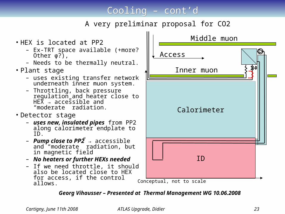
Cooling – cont’dCooling – cont’d
ID
Calorimeter
Inner muon
Middle muon
Access
Conceptual, not to scale
• HEX is located at PP2– Ex-TRT space available (+more?
Other φ?),– Needs to be thermally neutral.
• Plant stage – uses existing transfer network
underneath inner muon system.– Throttling, back pressure regulation
and heater close to HEX → accessible and “moderate” radiation.
• Detector stage – uses new, insulated pipes from PP2
along calorimeter endplate to ID.– Pump close to PP2 → accessible
and “moderate” radiation, but in magnetic field
– No heaters or further HEXs needed– If we need throttle, it should also be
located close to HEX for access, if the control allows.
A very preliminar proposal for CO2
Georg Vihausser – Presented at Thermal Management WG 10.06.2008
Cartigny, June 11th 2008 ATLAS Upgrade, Didier 24
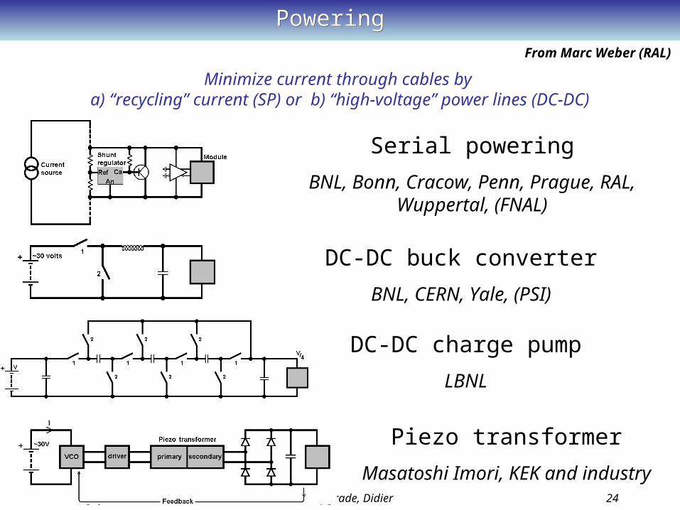
PoweringPowering
Serial powering
BNL, Bonn, Cracow, Penn, Prague, RAL, Wuppertal, (FNAL)
DC-DC buck converter
BNL, CERN, Yale, (PSI)
DC-DC charge pump
LBNL
Minimize current through cables by a) “recycling” current (SP) or b) “high-voltage” power lines (DC-DC)
Piezo transformer
Masatoshi Imori, KEK and industry
From Marc Weber (RAL)

Cartigny, June 11th 2008 ATLAS Upgrade, Didier 25
Element of Power SystemsElement of Power Systems
IP: independent powering; SP: Serial powering; PP: parallel powering
Off-detector power supplyConstant-current source;
HV supply
Cables and power distribution scheme:
IP; SP; PP
On-detector power supplies:
regulators; converters;transformers
Monitor + control system
DCS; protection; by-pass
On-detector supplies and understanding cables is most urgent, but we need all element!
It is also time to see how elements would come together in a system.
Cartigny, June 11th 2008 ATLAS Upgrade, Didier 26
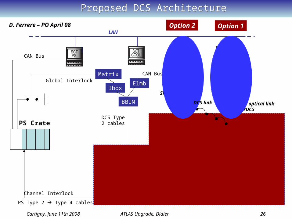
Proposed DCS ArchitectureProposed DCS Architecture
SCTDAQ
PS Crate
Cooling Temp
Environmental (Super-Module)
Hybrid Temp
Hybrid Power
SMC Hybrid
BBIM
Ibox
Matrix
Elmb
CAN Bus
CAN Bus
Global InterlockROD
BOC
5 GB/s optical linkData/DCS
Channel Interlock
LAN
DCS Type 2 cables Env.
Structure
DetectorPS Type 2 Type 4 cables
SCTDCS
Elmb
CAN Bus
SPI bus daisy chain
Option 2 Option 1
DCS link
D. Ferrere – PO April 08

Cartigny, June 11th 2008 ATLAS Upgrade, Didier 27
Module Integration - StaveModule Integration - Stave
• ATLAS specific design: 10, 10x10 cm sensors/side, doubled sided measurement• Embedded cooling and bus cable• Thickness and mass (Xo) depend upon choice of coolant, hybrid technology• Complete and inclusive except for barrel support cylinder and fixation points• Straightforward generalization to outer barrel modules• Baseline design has hybrids glued directly on sensors and small gaps in Z• Alternatives have been studied which include bridges and closed gaps
Bus cable
Hybrids Coolant tube structure
Carbon honeycomb or foam
Carbon fiberfacing
Readout IC’s
Silicon sensors
Material budget announced to be relatively light: ~ 2.2 % for CO2~ 2.7 % for C3F8
(Only for th
e Stave)

Cartigny, June 11th 2008 ATLAS Upgrade, Didier 28
30 modules with ABCD & serial power(ABCnext will be 30 V)
2 adjacent modules glued on a stave
Output noise
Input Noise vs Strip Length
0
200
400
600
800
1000
1200
1400
1600
0 2 4 6 8 10 12 14
Strip Length [cm]
Electrons
Unbonded
Stave 2007 Stave 2006
SCT
Comparison
Module Integration – Stave07Module Integration – Stave07
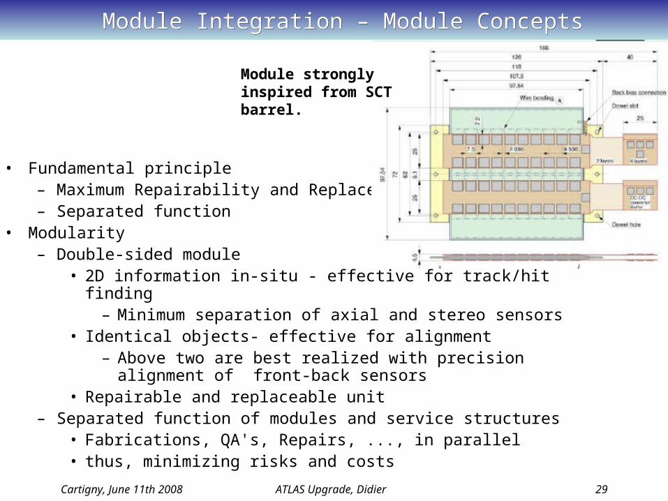
Module Integration – Module ConceptsModule Integration – Module Concepts
Cartigny, June 11th 2008 ATLAS Upgrade, Didier 29
• Fundamental principle– Maximum Repairability and Replaceabiltiy– Separated function
• Modularity– Double-sided module
• 2D information in-situ - effective for track/hit finding – Minimum separation of axial and stereo sensors
• Identical objects- effective for alignment– Above two are best realized with precision alignment of front-
back sensors• Repairable and replaceable unit
– Separated function of modules and service structures• Fabrications, QA's, Repairs, ..., in parallel• thus, minimizing risks and costs
Module strongly inspired from SCT barrel.
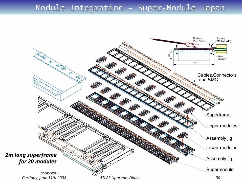
Module Integration – Super-Module JapanModule Integration – Super-Module Japan
Cartigny, June 11th 2008 ATLAS Upgrade, Didier 30
2m long superframe for 20 modules

Module Integration – Super-Module JapanModule Integration – Super-Module Japan
Circumferential mounting with support jigs for 2 m long SM
Cartigny, June 11th 2008 ATLAS Upgrade, Didier 31

Module Integration – Local Support UniGeModule Integration – Local Support UniGe
Cartigny, June 11th 2008 ATLAS Upgrade, Didier 32
Individual module mountingFeb 07
10 Module structure
Apr 07
With longitudinal insertion mechanism
Jul 07Local Support Row (LSR)
Dec 07 Local Support with anchorage points (Valencia)
Jan 08 Simplified Local Support
Fabrication aspect taken into account
Prototype program en route
DemonstratorMay 08
June 08 Review

Module Integration – Local Support UniGeModule Integration – Local Support UniGe
Cartigny, June 11th 2008 ATLAS Upgrade, Didier 33
Stiff and self-handling structure.Module and barrel fixation precision as assembled!
Local support on the jig for the assembly
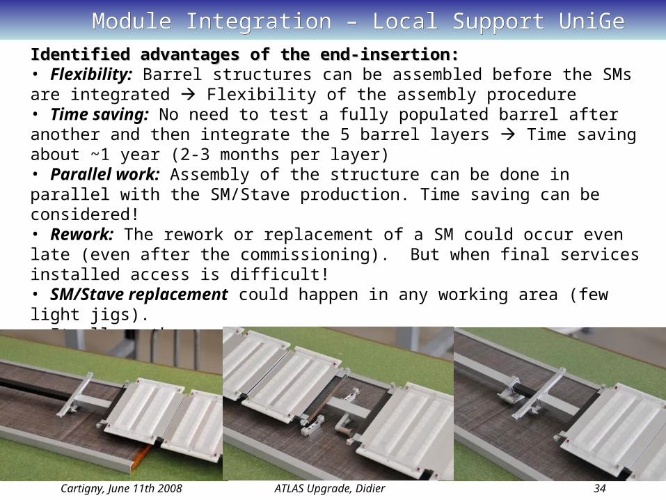
Module Integration – Local Support UniGeModule Integration – Local Support UniGe
Cartigny, June 11th 2008 ATLAS Upgrade, Didier 34
Identified advantages of the end-insertion:Identified advantages of the end-insertion:• Flexibility: Barrel structures can be assembled before the SMs are integrated Flexibility of the assembly procedure• Time saving: No need to test a fully populated barrel after another and then integrate the 5 barrel layers Time saving about ~1 year (2-3 months per layer)• Parallel work: Assembly of the structure can be done in parallel with the SM/Stave production. Time saving can be considered!• Rework: The rework or replacement of a SM could occur even late (even after the commissioning). But when final services installed access is difficult!• SM/Stave replacement could happen in any working area (few light jigs).• It allows the use of either a single skin barrel cylinder with reinforcing rings or a CF sandwich • It allows double layer structure BUT … (see next slides)• Geometrical survey of the pre-assembled structures with and without SM/Stave.
Module Integration – Local Support UniGeModule Integration – Local Support UniGe
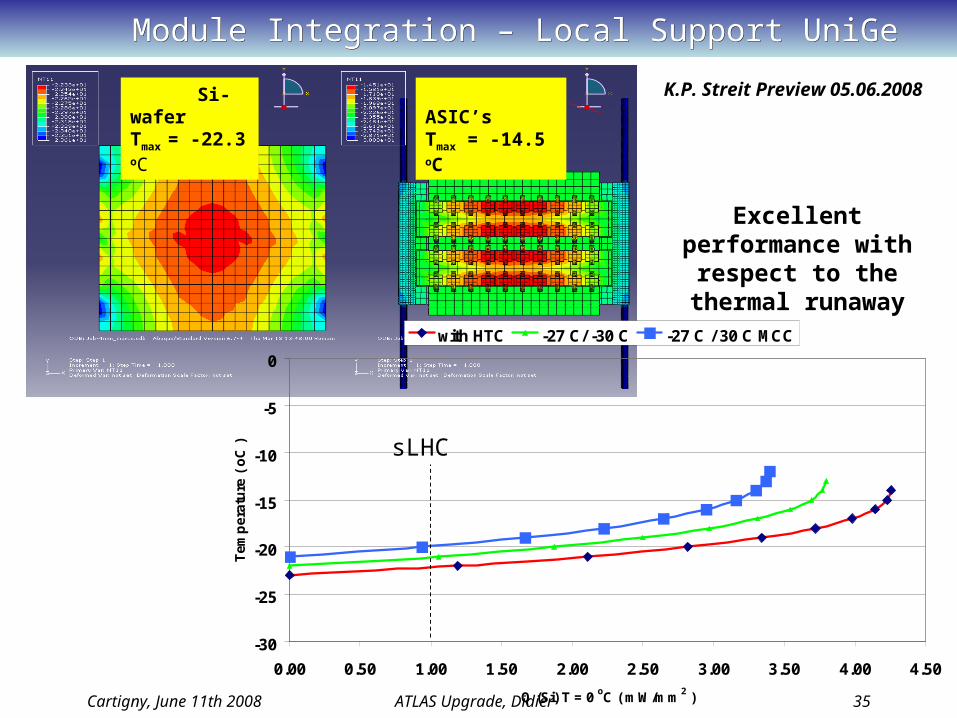
Cartigny, June 11th 2008 ATLAS Upgrade, Didier 35
Si-waferTmax = -22.3 oC
ASIC’sTmax = -14.5 oC
-30
-25
-20
-15
-10
-5
0
0.00 0.50 1.00 1.50 2.00 2.50 3.00 3.50 4.00 4.50
Q (Si) T = 0 oC ( mW/mm2 )
Tem
per
atu
re (
oC
)
with HTC -27 C/ -30 C -27 C / 30 C MCC
Excellent performance with respect to the thermal runaway
sLHC
K.P. Streit Preview 05.06.2008
Module Integration – Wing Support UKModule Integration – Wing Support UK
Cartigny, June 11th 2008 ATLAS Upgrade, Didier 36
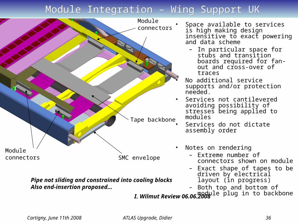
• Space available to services is high making design insensitive to exact powering and data scheme
– In particular space for stubs and transition boards required for fan-out and cross-over of traces
• No additional service supports and/or protection needed.
• Services not cantilevered avoiding possibility of stresses being applied to modules
• Services do not dictate assembly order
• Notes on rendering– Extreme number of connectors
shown on module – Exact shape of tapes to be
driven by electrical layout (in progress)
– Both top and bottom of module plug in to backbone
SMC envelope
Tape backbone
Module connectors
Module connectors
Pipe not sliding and constrained into cooling blocksAlso end-insertion proposed…
I. Wilmut Review 06.06.2008
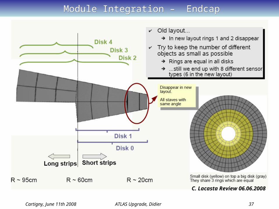
Module Integration – EndcapModule Integration – Endcap
Cartigny, June 11th 2008 ATLAS Upgrade, Didier 37
C. Lacasta Review 06.06.2008
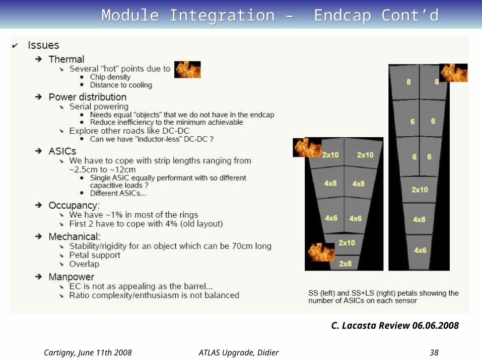
Module Integration – Endcap Cont’dModule Integration – Endcap Cont’d
Cartigny, June 11th 2008 ATLAS Upgrade, Didier 38
C. Lacasta Review 06.06.2008

Module Integration – Review CloseoutModule Integration – Review Closeout
Cartigny, June 11th 2008 ATLAS Upgrade, Didier 39
• The stave appears to have a number of advantages and is the most advanced development. It should be the collaborations priority to complete this understanding by setting up collaboration-wide subgroups to tackle critical issues (see p6 but start to complete this list and set up groups today).
• The second priority should be to accelerate the development of an EC solution. The hope is that the stave concept can be morphed into a petal or ring and benefit from the barrel development.
• There are open issues with the stave which might result in a fall-back. Concentrating all effort on the stave is not risk-free. Revisit progress at Nikhef.
• Review committee will circulate a detailed list of concerns in a few days
Recommendation summaryRecommendation summary
M. Tyndel Review 07.06.2008
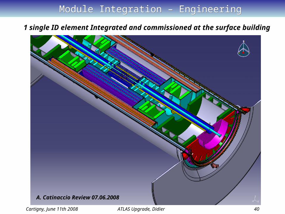
Module Integration – EngineeringModule Integration – Engineering
Cartigny, June 11th 2008 ATLAS Upgrade, Didier 40
1 single ID element Integrated and commissioned at the surface building
A. Catinaccio Review 07.06.2008

Module Integration – Engineering & ServicesModule Integration – Engineering & Services
Cartigny, June 11th 2008 ATLAS Upgrade, Didier 41
Possible connector implementation on the SMC!
Only 60 mm space between interlinks!
D. Ferrere Preview 05.06.2008

ATLAS Strip Upgrade - UniGe InvolvementsATLAS Strip Upgrade - UniGe Involvements
Cartigny, June 11th 2008 ATLAS Upgrade, Didier 42
Asics: Digital Architecture & Simulation: pipeline, Derandomizer, Data Compression Logic, Readout Logic and Control; Check after place and route!
250nm submission January 2008 130nm design from January 2008
Detectors: 135 sensors of size10X10cm2 ordered to HamamatsuUniGe ordered 15 sensors: 12 p-stop and 3 p-spray Sensor characterization will be made and compared with other institutes
Module Concept: UniGe investigated 2 concepts module directly mounted on barrel or mounted on an intermediate local support!
UniGe operates 3D Thermal FEA to evaluate and optimize the designStrategy is to make prototype modules in 2008 with above detectors and Asics
DCS: Involvement in the strategy and decision for the detector safety. DCS will be part of the system design to optimize the service and resource issues.
Mechanical Engineering: Involvement in the structure and service design.

Few ConclusionsFew Conclusions
Cartigny, June 11th 2008 ATLAS Upgrade, Didier 43
SLHC is clearly in the continuity of the machine and detector operation Phase 1 will be to increase the luminosity up to a factor 10 (1035 cm-2s-1 ) ATLAS and CMS are considering options to Upgrade the detectors in 2016 The ATLAS Inner Tracker will be completely renewed (no TRT) and is in a design and specification phase The B-layer replacement is foreseen already in 2012 using 3-D sensors The major challenges are: Service and material reductions, Cooling, Powering scheme The time scale is short and there is almost no time for R&D Working groups start smoothly to grow and to be active UniGe involved in various topics and keep an eye on the B-layer replacement activities Next event:
•ID Upgrade Workshop Nov 2008 at Nikhef