Cellwasher 2 Cell Washing System
144
Service Manual SORVALC Cellwasher 2 CELL WASHING SYSTEM SORVALL® Products Newtown, Connecticut U.S.A. SORVALL Centrifuges PN 04624-5 Issued February 1994
Transcript of Cellwasher 2 Cell Washing System

Service Manual
SORVALC Cellwasher 2
CELL WASHING
SYSTEM
SORVALL® Products
Newtown, Connecticut
U.S.A.
SORVALL Centrifuges
PN 04624-5
Issued February 1994
User
Parts list Updated Apr '05

Cellwasher 2 Service SORVALL®lnstrumentS
This manual is a guide for service of the
SORVALL® Cellwasher 2 Cell Washing System
Data herein has been verified and validated and is believed adequate for the intended use
of the instrument. If the instrument or procedures are used for purposes over and above
the capabilities specified herein, confirmation of their validity and suitability should be
obtained, otherwise, DuPont does not guarantee results and assumes no obligation or
liability. This publication is not a license to operate under, nor a recommendation to
Infringe upon, any process patents.
This service manual is intended as a service aid. While the manual is kept current and
includes information regarding significant design changes, specific designs may still vary
from instrument to instrument.
This service manual is intended for use only by service personnel who have been trained
by DuPont. Due to the high electrical potential in this centrifuge, untrained individuals
must not attempt any of the procedures in this service manual.
NOTES, CAUTIONS, and WARNINGS within the text of this manual are used to emphasize
important and critical instructions:
WARNING A Warning informs the operator of a hazard or an unsafe practice that could
result in personal injury, affect the operator's health, or contaminate the
environment.
CAUTION A Caution informs the operator of an unsafe practice that could result in
damage of equipment.
NOTE A Note highlights essential information.
Ili^^^^^^^^^^^^^^^^^^^^^^^^^^ ! ' '
^^^NG';'^'^'6'!;''1:^;":,!^
When using radioactive, toxic, or pathogenic material, be aware of all .:
characteristics of the material and the hazards associated with it. In the .
I?''lew^^^ltt'lii^^
rotor can protect you from the particles dispersed into the air. To protect
^['licit^
^'eiiilitiil^^
!:::^::;^3(m£te::NOTS!USi:iM^^
^'^oi'iilltBiiivl'ti^^
ii

Sorvall® Instruments Cellwashcr 2 Service
Table of Contents
Paragraph Page
1-1.
1-2.
1-3.
1-4.
2-1.
2-2.
2-3.
2-4.
2-5.
2-6.
3-1.
3-2.
3-3.
4-1.
4-2.
4-3.
4-4.
4-5.
4-6.
4-7.
4-8.
4-9.
4-10.
Section I. INTRODUCTION
Intended Users .................................... 1-1
Warnings and Cautions ..............................1-1
Service Decontamination Policy. ....................... 1-1
Warranty Responsibility ............................. 1-2
Section 2.
DESCRIPTION, INSTALLATION and OPERATION
Description of the Cellwasher 2 ........................ 2-1
Cellwasher 2 Specifications ........................... 2-1
Installation Information. ............................. 2-2
Cellwasher 2 Operation .............................. 2-10
Emergency Sample Recovery .......................... 2-17
Condensed Operating Instructions ..................... 2-18
APPENDED: Condensed Operating Instructions ........... 2-19s
Section 3. MAINTENANCE
Inspection and Cleaning ............................. 3-1
Tubing Replacement ................................ 3-5
Cellwasher 2 Preventive Maintenance Procedure ........... 3-5
APPENDED: Preventive Maintenance Checklist ........... 3-9
Section 4. MECHANICAL THEORY
Controls ......................................... 4-1
Flexible Drive Mounting ............................. 4-1
Cabinet ......................................... 4-1
Air Flow ......................................... 4-1
Motor ........................................... 4-1
Safety Latch ...................................... 4-1
Saline Pump System ................................ 4-2
Flow Detector ..................................... 4-2
Flow Control Clamp ................................ 4-2
Motor Antirotation Clutch ............................ 4-2
in
Rev. 11/90

Cellwashcr 2 Service Sorvall® Instruments
Table of Contents (continued)
Paragraph Page
5-1.
5-2.
5-3.
5-4.
5-5.
6-1.
6-2.
6-3.
6-4.
8-1.
8-2.
8-3.
8-4.
8-5.
8-6.
8-7.
8-8.
8-9.
8-10.
8-11.
Section 5. ELECTRICAL THEORY
System Description ................................. 5-1
Touch Switch Panel. ................................ 5-31
Interface PC Board ................................. 5-31
Microcomputer PC Board ............................ 5-37
Electronics Module ................................. 5-50
Section 6. APPLICATIONS
Cellwasher 2 Application ............................. 6-1
Compatibility Testing ............................... 6-1
Cellwasher 2 Washing Cycle .......................... 6-2
Glossary of Blood Banking Terms ...................... 6-6
Section 7. TROUBLESHOOTING
Section 8. REPAIR and REPLACEMENT PROCEDURES
Base Plate Removal................................. 8-1
Cabinet Removal................................... 8-1
Front Panel Removal ................................ 8-2
Power Switch Replacement ........................... 8-3
Pump Replacement................................. 8-3
Pump Motor Replacement ............................ 8-3
Flow Detector Replacement........................... 8-4
Motor Replacement................................. 8-4
Interface Printed Circuit
Board Replacement................................ 8-4
Microcomputer Printed Circuit
Board Replacement................................ 8-5
Fuse Replacement.................................. 8-5
IV
Rev. 11/90

Son/all® Instruments Cellwasher 2 Service
Table of Contents (continued)
Paragraph Page
Section 9. KIT INSTRUCTIONS
9-1.
9-2.
9-3.
9-4.
9-5.
9-6.
9-7.
Figure
2-1.
2-2.
2-3.
2-4.
2-5.
3-1.
3-2.
5-1.
5-2.
5-3.
5-4.
5-5.
5-6.
Tubing Replacement Kit (PN 04632) .................... 9-2
Collector Seal Replacement Kit (PN 04353) ............... 9-9
Retainer Ring Replacement Kit (PN 12850) ............... 9-12
Lid Latch Assembly Replacement
Kit (PN 12792).................................... 9-14
Saline Shield Kit (PN 12811) .......................... 9-19
Triac-Interface Printed Circuit Board
Replacement Kit (PN 12816) ......................... 9-20
Adapter Clip Installation Kit (PN 04330) ................. 9-23
Section 10. ILLUSTRATED PARTS LIST
List of Illustrations
Page
Cellwasher 2 Tubing Diagram ......................... 2-4
Stainless Steel Rotating Bowl Installation ................ 2-2
Distributor Installation .............................. 2-9
Cellwasher 2 Controls and Indicators ................... 2-10
Location of Mechanical Override ....................... 2-18
Exploded View, Collecting Ring Assembly
(SN 8702302 and higher) ........................... 3-3
Exploded View, Collecting Ring Assembly
(SN 8702301 and lower) ............................ 3-5
System Schematic, Cellwasher 2 ....................... 5-3
Wiring Diagram, Cellwasher 2 ......................... 5-5
Microcomputer PC Board ............................ 5-7
Schematic, Microcomputer PC Board ................... 5-11
Triac-Interface PC Board (PN 04834 Revision 0,
SN 8503865 and higher) ............................ 5-16
Schematic, Triac-Interface PC Board (PN 04537
Revision 2, SN 8503865 and higher) ................... 5-17
v
Rev. 11/90

Cellwasher 2 Service SORVALL®lnstrumentS
List of Illustrations (continued)
Figure Page
5-10. Schematic, Onterface PC Board (PN 04537
Revision 1, SN 8503864 and below) ........................ .5-25
5-11. Cellwasher 2 Automatic Wash Sequence ...................... .5-30
5-12. Indicator Current Path ................................... .5-31
5-13. Schematic, Touch Switch Panel ............................ .5-33
5-14. Interface PC Board, Test Set-Up #1 .......................... .5-35
5-15. Interface PC Board, Test Set-Up #2 .......................... .5r36
5-16. Microcomputer Board Input/Output Configuration .............. .5-38
5-17. Microcomputer Scan Routine .............................. .5-39
5-18. Creating New Input/Output Formats ........................ .5-41
5-19. Digital Time Display Segments ............................. .5-42
5-20. Starting in Manual (High or Low) Mode, Logic Flow Chart ......... .5-47
5-21. Starting from Check Mode, Logic Flow Chart ................... .5-48
5-22. Starting in Auto Mode, Logic Flow Chart ...................... .5-49
7-1. Location of Decant Coil and Drive Ring ....................... .7-7
7-2. Location of Lift Plate Ring ................................. .7-7
9-1. Tubing Diagram: Parts Location ............................ .9-2
9-2. Adjustable Tubing Clamp Location .......................... .9-6
9-3. Adjustable Tubing Clamp ................................. .9-8
9-4. CW-1 Collecting Ring Assembly Exploded View ................. .9-10
9-5. Cellwasher 2 Collecting Ring Assembly Exploded View ........... .9-11
9-6. Cabinet Machine Drawing ................................. .9-17
9-7. Adhesive Location ....................................... .9-20
9-8. Installing an Adapter Clip ................................. .9-24
10-1. Cellwasher 2 Assembly .................................... 10-5
10-2. Chassis and Component Assembly ........................... 10-11
10-3. Drive Motor Assembly ..................................... 10-15
List of Tables
Table Page
2-1. Parts Location: Tubing Diagram ............................ .2-4
2-2. Cellwasher 2 Controls and Indicators ........................ .2-9
5-1. Component Identification, Microcomputer PC Board .............. 5-8
5-2. Component Identification, Triac-Interface PC Board
(PN 04834, Revision 0, SN 8503865 and higher) ............... .5-15
5-3. Triac PC Board Component Identification ..................... .5-19
5-4. Component Identification, Interface PC Board
(PN 04536, Revision 2, SN 8503864 and below) ............... .5-23
5-5. Automatic Wash Sequence ................................ .5-30
5-6. Microcomputer Scan Map ................................. .5-40
5-7. Electronics Control System ................................ .5-43
vi Rev. 4/96
SORVALL® Instruments Cellwashcr 2 Service
List of Tables (continued)
Table Page
6-1. Applications Troubleshooting Chart: False Negative Results ........ 6-3
6-2. Applications Troubleshooting Chart: False Positive Results ........ .6-4
6-3. Applications Troubleshooting Chart: Inconsistent Reaction
Strength ............................................. .6-5
7-1. Troubleshooting Chart: Drive Motor ......................... .7-2
7-2. Troubleshooting Chart: Power .............................. .7-3
7-3. Troubleshooting Chart: Saline Fill ........................... .7-4
7-4. Troubleshooting Chart: Decant .............................. 7-5
7-5. Troubleshooting Chart: Lid Latch ........................... .7-6
10-1. Suggested Spare Parts, CeUwasher 2 ......................... 10-2
10-2. CeUwasher 2 Assembly .................................... 10-3
10-3. Chassis and Component Assembly ........................... 10-7
10-4. Drive Motor Assembly ..................................... 10-13
Rev. n/90 vii/viii

SORVALL® Instruments Cellwasher 2 Service
Section 1. INTRODUCTION
This manual is a service guide for the Sorvall Cellwasher 2 Cellwashing
System. It contains descriptive information; preventive maintenance
procedures; mechanical and electrical theories of operation; applications
information; a troubleshooting guide; field procedures for repairs and
replacements; and an illustrated parts list for ordering replacement
parts.
1-1. Intended Users
This manual has been written for qualified service personnel who are
familiar with factory methods for performing repairs, adjustments and
calibrations. While the descriptive information and operating
procedures contained in this manual are useful to the cellwasher
operator, the replacement and calibration procedures (especially those
involving electrical circuitry) should be performed only by qualified
service personnel.
1-2. Warnings and Cautions
Warnings and cautions appear throughout the manual. Service personnel
are expected to be familiar with their meaning (see page ii) and to
read them before servicing an instrument.
1-3. Service Decontamination Policy
———————————————————————— WARNING ————————————————————————
Either biological or radioactive contamination of the
instrument and/or rotor can occur because of the samples
likely to be processed. Always be aware of this
possibility and take normal precautions. Use appropriate
decontamination procedures should exposure occur.
If an instrument or rotor that has been used with biohazardous material
requires servicing by DuPont personnel, either at the customer's
laboratory or at a DuPont facility, comply with the following procedure
to ensure the safety of DuPont personnel:
• Clean the instrument and/or rotor to be serviced of all
encrusted material, and decontaminate it prior to servicing by
the representative. There must be no radioactivity detectable
by survey equipment.
• Attach a completed Decontamination Information Certificate
(SORVALL Instruments Form No. IPDP-59) to the instrument or
rotor.
Rev. 11/90 1-1

Cellwasher 2 Service SORVALL® Instruments
If the instrument and/or rotor to be serviced does not have a
Decontamination Information Certificate attached, and in DuPont's
opinion presents a potential biohazard, the DuPont representative will
not service the equipment until proper decontamination and certification
is complete. If DuPont receives an instrument or rotor at its Service
facilities which, in DuPont's opinion is a biohazard/ the sender will
be contacted for instructions as to the disposition of the equipment.
Disposition costs will be borne by the sender.
Decontamination Information Certificates are included with these
instructions. Additional certificates are available from the local
Technical or Service Representative. In the event these certificates
are not available, a written statement certifying that the instrument
and/or rotor has been properly decontaminated and outlining the
procedures used will be acceptable.
NOTE
The Service Representative will note on the Customer
Service Repair Report if decontamination was required, and
if so, what the contaminant was and what procedure was
used. If no decontamination was required, it will be so
stated.
1-4. Warranty Responsibility
Whenever service of the instrument is attempted by anyone other than
an employee of DuPont or an authorized DuPont representative, the
individual performing the service is assuming the risk of voiding the
instrument warranty, which is as follows:
E. I. Du Pont de Nemours and Company makes no warranty of any
kind, expressed or implied, except as stated in this warranty
policy.
The Sorvall® Cellwasher 2 Cell Washing instrument and DA-12
Rotor are warranted to be free from defects in materials and
workmanship for a period of one (1) year from the date of
delivery. DuPont will, at its option, repair or replace and
return free of charge any part which is returned to its factory
within said period, transportation prepaid by user, and which
is found upon inspection to have been defective in materials
or workmanship. This warranty does not include normal wear
from use; it does not apply to any instrument or part which
has been altered by anyone other than an employee of DuPont,
nor to any instrument which has been damaged through accident,
negligence, failure to follow operating instructions, the use
of electric currents or circuits other than those specified
on the plate affixed to the instrument, misuse or abuse.
DuPont reserves the right to change, alter, modify or improve
any of its instruments without any obligation to make
corresponding changes to any instrument previously sold or
shipped.
1.2 Rev. 11/90

SORVALL® Instruments Cellwasher 2 Service
THE FOREGOING OBLIGATIONS ARE IN LIEU OF ALL OTHER OBLIGATIONS AND
LIABILITIES INCLUDING NEGLIGENCE AND ALL WARRANTIES/ OF
MERCHANTABILITY OR OTHERWISE, EXPRESSED OR IMPLIED IN FACT OR BY
LAW, AND STATE OUR ENTIRE AND EXCLUSIVE LIABILITY AND BUYER'S
EXCLUSIVE REMEDY FOR ANY CLAIM OR DAMAGES IN CONNECTION WITH THE
SALE OR FURNISHING OF GOODS OR PARTS/ THEIR DESIGN, SUITABILITY
FOR USE, INSTALLATION OR OPERATION. DUPONT WILL IN NO EVENT BE
LIABLE FOR ANY SPECIAL OR CONSEQUENTIAL DAMAGES, AND OUR LIABILITY
UNDER NO CIRCUMSTANCES WILL EXCEED THE CONTRACT PRICE FOR THE GOODS
FOR WHICH LIABILITY IS CLAIMED.
If there are any questions concerning the effect of service on the
warranty, contact the nearest representative of Sorvallo Instruments.
1-3/1-4

SORVALL® Instruments Cellwasher 2 Service
Section 2. DESCRIPTION, INSTALLATION and OPERATION
This section describes the Sorvall® Cellwasher 2 and provides speci¬
fications, installation information, and instructions for operating
the instrument.
2-1. Description of the Cellwasher 2
The SORVALL® Cellwasher 2 is designed to perform the washing phase of
the Coomb's Procedure automatically. The centrifuge and saline pump
are contained in one cabinet, with the operating controls on the front
panel.
The Cellwasher 2 is microprocessor-controlled, featuring a front panel
with sensor-touch controls and a digital timer for the wash cycle. Other
features include a saline detect system with an audible low-saline
warning and an agitate cycle that ensures complete resuspension of
cells and eliminates manual agitation.
2-2. Cellwasher 2 Specifications
Dimensions:
Width ............
Depth ............
Height, lid closed
Height, lid open .
Mass (Weight)
Electrical Requirements*:
Motor Type
Speed** for 60 Hz models:
Low
High
Decant
Speed** for 50 Hz models:
Low ...................
High ..................
Decant ................
31.8 cm (12.5 in)
35.6 cm (14.0 in)
36.8 cm (14.5 in)
57.2 cm (22.5 in)
16.4 kg (36.0 Ib)
115 V + 10%, 60 Hz, 5A
or
230 V + 10%, 50 Hz, 2A
3 speed induction
1150 to 1200 rpm
3500 to 3600 rpm
600 rpm
1450 to 1500 rpm
2950 to 3000 rpm
600 rpm
(continued)
2-1

Cellwasher 2 Service SORVALL® Instruments
Decibel .................................... 67 Db
Length of Modes:
Automatic ................................ Total cycle time 80
seconds
Manual ................................... High or low, optional,
up to 999 seconds if
timed; indefinite if
in HOLD
Tube Sizes:
Diameter ................................. 12 mm + 0.09 mm
or
10 mm + 0.09 mm*
Length ................................... 75 mm + 2 mm
Tube Material: ............................. High strength glass, such
as Pyrex® or Corex®
WARNING
Use only tubes which are guaranteed to be within the
specifications given above. If tubes outside these
specifications are used, test results will be affected,
the rotor and distributor could be damaged, and personal
injury could result.
2-3. Installation Information
a. Location
Place the Cellwasher 2 on a sturdy/ level bench or table near a sink,
drain, or waste container to receive decanted saline. The following
factors should be considered when selecting a location:
• Allow a 15 cm (6 inch) clearance behind the instrument for the
saline pump and tubing.
Allow a 61 cm (24 inch) clearance above the tabletop or bench
surface for the lid to open.
"Adapter Clips (PN 04330) are required when using 10 mm x 75 mm tubes in the DA-12 Rotor.
2-2 Rev. 11/93

SORVALL® Instruments Ccllwasher 2 Service
Drainage in the Cellwasher 2 is accomplished by gravity, so the
drain tubing must extend downward from the instrument to the
drain, sink, or waste receptacle.
The preferred location for the saline supply is either at or
above instrument level.
To obtain the best results, minimize tubing length from the
saline supply to the cellwasher.
CAUTION
Cooling air is drawn into the Cellwasher 2 from all four
sides of the base. Be sure that the entrances are not
obstructed.
If the saline supply reservoir is moved from its original location,
recheck the saline volume by priming the system as explained in
paragraph 2-4, b.
b. Electrical Requirements
The power cord for the Cellwasher 2 has a universal keyed plug that
inserts into a receptacle at the back of the instrument. The other end
must be connected to the appropriate power supply:
115 V + 10%, 60 Hz, 5A or 230 V + 10%, 50 Hz, 2.5A
as specified on the rating plate on the back of the instrument.
————————————————————— WARNING —————————————————————
The receptacle used should be a 3-wire system. If it is
not, the equipment must be grounded to earth to avoid the
possibility of electrical shock.
c. Tubing Installation
The Cellwasher 2 is shipped with the tubing already connected to the
instrument, but not installed in the peristaltic pump. To install the
tubing in the peristaltic pump, unwrap the bundle of tubing at the back
of the instrument and proceed as follows (refer to figure 2-1):
2-3

Cellwashcr 2 Service SORVALL® Instruments
1. Remove the four knurled thumbscrews from the peristaltic pump
and remove the front half of the pump housing. (Do not remove
the pump roller assembly.) Make sure that the pump rollers are
clean and move freely.
2. Turn the roller assembly so that one of the rollers is in the
11 o'clock position.
3. Without turning the rollers, place the pump tubing around the
rollers (the end with the connector should be on the left side) .
4. Pull up on the two ends of the pump tubing, and fit the tubing
into the pump housing around the rollers.
Figure 2-1. Cellwasher 2 Tubing Diagram
2-4 Rev. 4/96

SORVALL® Instruments Cellwasher 2 Service
Table 2-1. Parts Location: Tubing Diagram
(key to figure 2-1)
Item Description
I*
2
3
4
5
6
7
8
9
10
Overflow Tubing 15 cm (6 inches) long
Vent Tubing 15 cm (6 inches) long
Pump Tubing 25 cm (10 inches) long
Flow Tubing (to nozzle) 30 cm (12 inches) long
Discharge Tubing 20 cm (8 inches) long
Supply Tubing (to pump) 60 cm (24 inches) long
Drain Tubing 121 cm (48 inches) long
Pump Connector
Y-Connector
Adjustable Tubing Clamp
NOTE
Do not use a sharp object to fit the pump tubing in place
as this could puncture the tubing.
5. With the pump tubing in place, replace the front half of the
pump housing. Stretch the ends of the tubing while fitting the
pump housing in place to eliminate slack in the tubing.
6. Make sure that the halves of the housing are evenly mated. A
gap indicates that the pump tubing is pinched; if so, remove
the front half of the housing and repeat steps 3 through 6.
7. Secure using the four thumbscrews (removed in step 1) and hand
tighten.
8. Check the pump tubing installation by turning the roller
assembly shaft counterclockwise using pliers (should rotate
smoothly without pinching).
9. Install the flow control valve as follows:
a. Cut a length of tubing 60 cm (24 inches) long to be used as
supply tubing. Attach the supply tubing to the pump connector
on the left side of the pump housing.
* In the event of saline residua] in the rotor chamber (e.g. from overfill of tubes or tube breakage) saline will exit through this tube. Under
normal operating conditions, saline will exit through the drain tubing, not through the overflow tubing.
Rev. 11/93 2-5

Cellwasher 2 Service SORVALL® Instruments
b. Place the valve over the supply line at a convenient point
and insert the end of the supply tubing into a saline supply
reservoir.
c. Connect the pump tubing from the right side of the pump
housing to the inlet port of the flow detector.
10.Into the adjustable tubing clamp located to the left of the
peristaltic pump, position the bottom leg of the Y-Connector
(with discharge tubing attached).
11. Holding the Y-Connector in place with one hand, fold the inner
strap over the Y-Connector/discharge tubing. Then, fold the
outer strap over the inner strap and push on the outer strap
to lock in place. You will hear a "click" when the clamp is
secured.
12 .Make sure the drain tubing flows downward to an open sink, drain,
or waste receptacle since drainage in the Cellwasher 2 is
accomplished by gravity. Use the shortest length of drain tubing
possible and make sure the tubing is positioned so there is no
upward travel to result in a "trap" for collected waste fluid.
13.Ideally, the drain tubing should be positioned so that it can
not become immersed in collected waste fluid. However, if there
is a possibility that the drain tubing will become immersed in
waste fluid, cut the drain tubing at a convenient point near
the waste receptacle and insert the Y-Connector. Always insert
a Y-Connector in the drain line when using a waste container
for discharged saline.
NOTE
The Y-Connector prevents pressure from building up in
the line due to submerged tubing or air blockage. Failure
to vent the drain tubing by installing a Y-Connector can
result in improperly decanted samples.
If the saline supply reservoir is moved from its original
location, recheck the saline volume by priming the system
as explained in paragraph 2-4, b.
14.If necessary, use additional tubing and connectors from
the Tubing Kit to supply saline and discharge waste
properly.
2-6 "s"-4/^

SORVALL® Instruments Ccllwasher 2 Service
WARNING
Saline solution from some manufacturers contains sodium
azide as a preservative. If this solution is discharged
directly down the drain, explosive azide salts may form
as the sodium azide reacts with the plumbing. Check with
your saline supplier before discharging saline from the
Cellwasher 2 into a drain.
CAUTION
All saline solutions have long term corrosive effects.
Routine cleaning and maintenance (as described in Section
3) are essential to ensure safe and efficient operation
of the Cellwasher 2.
d. DA-12 Dual Angle Rotor and Distributor Installation
1. Open the lid of the Cellwasher 2.
———————————————————— WARNING ————————————
All Sorvall® Cellwashers manufactured prior to February
1984 were supplied with a plastic rotating bowl assembly
which required annual replacement. All plastic rotating
bowl assemblies are more than one (1) year old and should
be removed from service and discarded immediately. Failure
to do so can result in damage of equipment and/or personal
injury. Replace the plastic rotating bowl assembly with
a stainless steel rotating bowl assembly (PN 12796).
NOTE
There may be one or more holes in the stainless steel
rotating bowl assembly (PN 12796). These holes are for
balancing purposes only and will not effect the perform¬
ance of the stainless steel rotating bowl.
2. Position the stainless steel rotating bowl assembly over the
motor drive shaft. Align the two drive pins in the bowl with
the slot in the drive shaft (see figure 2-2). Slide the bowl
down the drive shaft until the two drive pins in the bowl engage
the rubber drive ring. Press the bowl down firmly.
2-7

Cellwasher 2 Service SORVALL® Instruments
MOTOR DRIVE
SHAFT
SLOT
ALIGNMENT
STAIN LESS STEEL ROTATING BOWL ASSEMBLY
DRIVE PINS
Figure 2-2. Stainless Steel Rotating
Bowl Installation
3. Slide the DA-12 Rotor over the drive shaft and lower it gently
into the rotating bowl.
4. Hold the edge of the rotating bowl and turn the rotor slowly
until the drive pins in the rotating bowl engage the rotor and
the rotor drops down onto the rotating bowl.
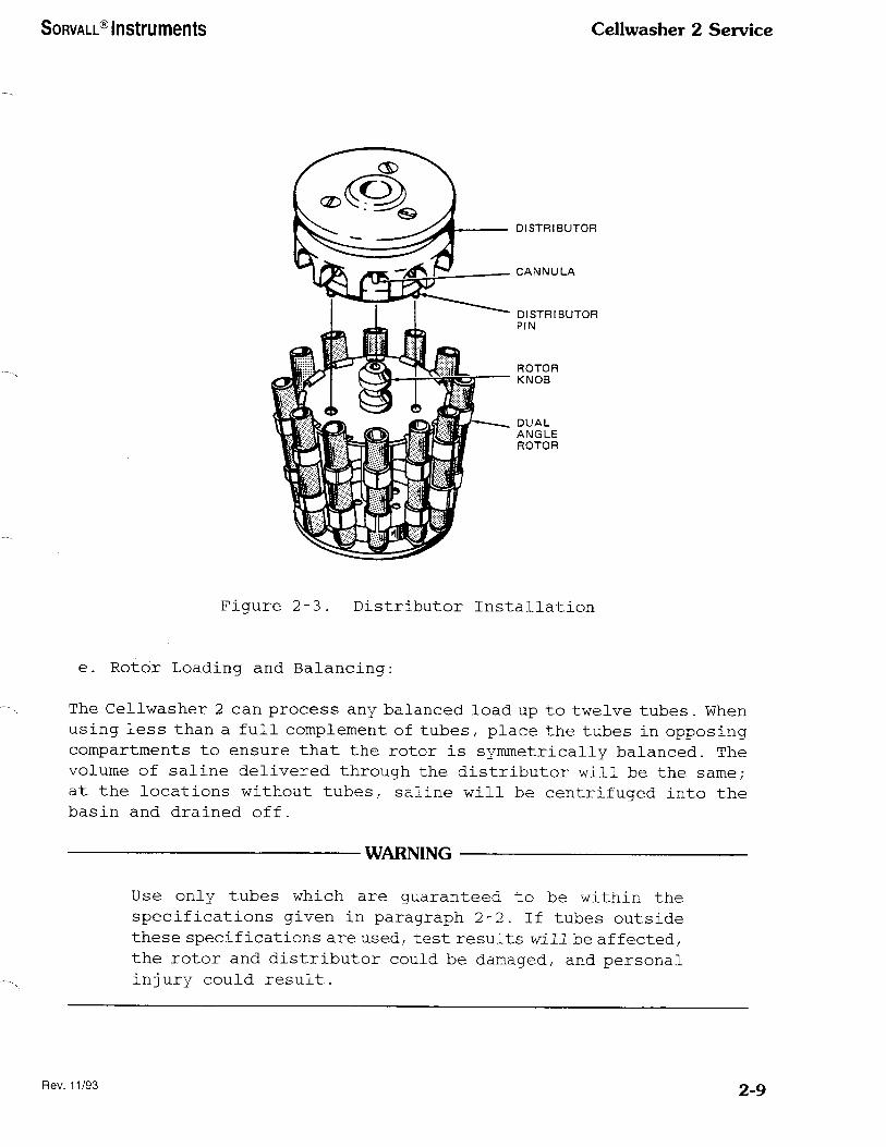
5. Place the distributor over the rotor knob (see figure 2-3) . Turn
the distributor until its three pins engage the three holes in
the rotor. Press the distributor down until it is completely
seated on the rotor.
CAUTION
If the stainless steel rotating bowl assembly, DA-12
Rotor, and distributor are not installed properly, damage
to the instrument will result. Before operating the
Cellwasher 2:
Make sure the drive pins in the rotating bowl assembly
are engaged in the rubber drive ring and in the rotor,
and that the distributor is firmly seated on the rotor
with all three distributor pins engaged in the rotor (see
figure 2-3).
2-8
SORVALL® Instruments Cellwasher 2 Service
DISTRIBUTOR
CANNULA
DISTRIBUTOR PIN
ROTOR KNOB
DUAL ANGLE ROTOR
Figure 2-3. Distributor Installation
e. Rotor Loading and Balancing:
The Cellwasher 2 can process any balanced load up to twelve tubes. When
using less than a full complement of tubes, place the tubes in opposing
compartments to ensure that the rotor is symmetrically balanced. The
volume of saline delivered through the distributor will be the same/¬
at the locations without tubes, saline will be centrifuged into the
basin and drained off.
WARNING
Use only tubes which are guaranteed to be within the
specifications given in paragraph 2-2. If tubes outside
these specifications are used, test results will be affected,
the rotor and distributor could be damaged, and personal
injury could result.
Rev. 11/93 2-9

Cellwasher 2 Service SORVALL® Instruments
2-4. Cellwasher 2 Operation
a. Controls and Indicators
All controls and indicators for the Cellwasher 2/ except the power
switch, are located on the front panel keyboard. The sensor-touch
controls register commands visually and/or audibly.
Power to the instrument is controlled by a switch located in the lower
right hand corner of the cellwasher, beneath the keyboard. The symbol
"1" indicates ON while the symbol "0" indicates the OFF position.
Switching the power off erases any manually programmed spin times from
the memory.
Table 2-2 describes the controls and indicators on the front panel.
Figure 2-4 shows their locations on the keyboard.
20 19 18 16 17 15 14 13
Figure 2-4. Cellwasher 2 Controls and Indicators
*LED, or light emitting diode, refers to the small amber light adjacent to the panel button.
2-10
SORVALL® Instruments Cellwasher 2 Service
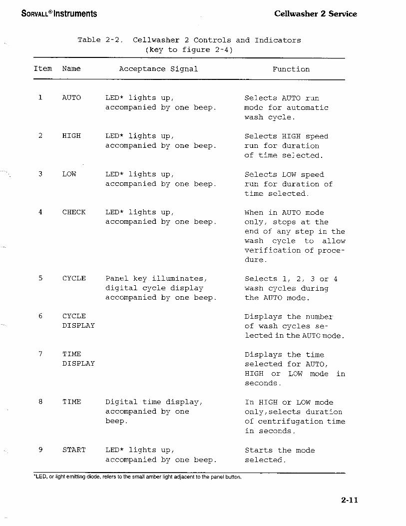
Table 2-2. Cellwasher 2 Controls and Indicators
(key to figure 2-4)
Item Name Acceptance Signal Function
AUTO LED* lights up,
accompanied by one beep.
HIGH LED* lights up,
accompanied by one beep.
Selects AUTO run
mode for automatic
wash cycle.
Selects HIGH speed
run for duration
of time selected.
LOW LED* lights up,
accompanied by one beep.
Selects LOW speed
run for duration of
time selected.
4 CHECK LED* lights up,
accompanied by one beep,
When in AUTO mode
only, stops at the
end of any step in the
wash cycle to allow
verification of proce¬
dure.
CYCLE
CYCLE
DISPLAY
Panel key.illuminates,
digital cycle display
accompanied by one beep,
Selects 1, 2, 3 or 4
wash cycles during
the AUTO mode.
Displays the number
of wash cycles se¬
lected in the AUTO mode.
7 TIME
DISPLAY
Displays the time
selected for AUTO,
HIGH or LOW mode in
seconds.
TIME Digital time display,
accompanied by one
beep.
In HIGH or LOW mode
only/selects duration
of centrifugation time
in seconds.
START LED* lights up,
accompanied by one beep.
Starts the mode
selected.
'LED, or light emitting diode, refers to the small amber light adjacent to the panel button.
2-11

Cellwasher 2 Service SORVALL® Instruments
Table 2-2. Cellwasher 2 Controls and Indicators
(key to figure 2-4, continued)
Item Name Acceptance Signal Function
10 STOP LED* lights up,
accompanied by one beep,
Stops the spin in
progress. In AUTO,
HIGH, or LOW mode,
the program will return
to conditions at the
start of the run.
11 PRIME Single beep. Primes the pump for
6 seconds.
12 AG Single beep. Agitates the rotor for
5 seconds to resuspend
cell
button.
13 CLEAR Single beep. In HIGH or LOW mode
only, clears digital
display so that time
can be reset.
14
15
ALARM
OFF
STEP
16 HOLD Single beep.
17 ALARM Single beep, ALARM
ON lights up.
18 SALINE SALINE lights up.
In AUTO mode only,
turns off the alarm.
In AUTO mode only, by¬
passes one step at a
time in the wash cycle
for each push
of the button.
In HIGH or LOW mode,
sets the centrifuge to
spin indefinitely.
In AUTO mode only,
activates an alarm that
sounds at the
end of the cycle.
Lights up when saline
supply is interrupted
during AUTO fill.
*LED, or light emitting diode, refers to the small amber light adjacent to the panel button.
2-12
SORVALL® Instruments Cellwasher 2 Service
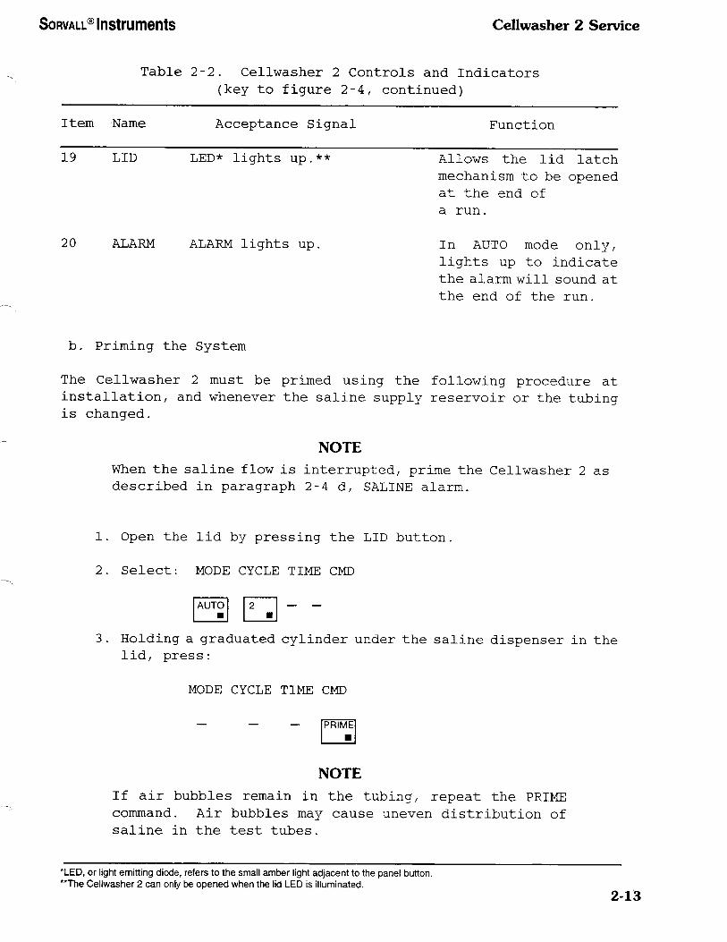
Table 2-2. Cellwasher 2 Controls and Indicators
(key to figure 2-4, continued)
Item Name Acceptance Signal Function
19 LID LED* lights up.**
20 ALARM ALARM lights up.
Allows the lid latch
mechanism to be opened
at the end of
a run.
In AUTO mode only/
lights up to indicate
the alarm will sound at
the end of the run.
b. Priming the System
The Cellwasher 2 must be primed using the following procedure at
installation, and whenever the saline supply reservoir or the tubing
is changed.
NOTE
When the saline flow is interrupted, prime the Cellwasher 2 as
described in paragraph 2-4 d, SALINE alarm.
1. Open the lid by pressing the LID button,
2. Select: MODE CYCLE TIME CMD
3. Holding a graduated cylinder under the saline dispenser in the
lid, press:
MODE CYCLE TIME CMD
NOTE
If air bubbles remain in the tubing, repeat the PRIME
command. Air bubbles may cause uneven distribution of
saline in the test tubes.
*LED, or light emitting diode, refers to the small amber light adjacent to the panel button.
"The Cellwasher 2 can only be opened when the lid LED is illuminated.
2-13

Cellwasher 2 Service SORVALL® Instruments
4 . Once air bubbles have been removed, empty the graduated cylinder
and repeat step 3 to determine saline volume (recommended fill
volumes are 54 ml for 12 mm tubes, 43 ml for 10 mm tubes) . If
the volume is not correct, rotate the flow control valve to
increase or decrease the flow of saline.
5. Repeat steps 3 and 4 until the correct volume is obtained.
NOTE
If the saline supply reservoir is moved or replaced, the
fill volume should be rechecked. To ensure proper cell
washing, check saline volume daily.
c. AUTO Mode
The basic operating sequence in the AUTO mode is as follows:
1. Press the LID button to open the lid.
2. Install rotor, tubes and distributor as explained in paragraph
2-3, d and e.
3. Close the lid.
4. Select: MODE CYCLE TIME CMD
5. For an audible signal at the end of the run, press ALARM ON.
6. Press START to begin the run.
7. At the end of the run, press ALARM OFF to turn off the audible
signal.
8. Once the lid LED is illuminated, press LID to open the lid.
NOTE
To ensure proper fill, press CHECK after beginning the
first run. At the end of the fill step, the Cellwasher
2 will stop. Examine the level of saline in each tube.
Fill is generally considered adequate if:
2-14
SORVALL® Instruments Cellwasher 2 Service
• the level of saline in all tubes is visible above the
metal bands holding the tubes,
the difference between maximum fill and minimum fill
is less than 0.7 ml/ or 3/8 inch for 12 mm tubes and
7/16 inch for 10 mm tubes.
Press START to continue the run.
d. SALINE alarm: this alarm will sound during the filling step if the
saline supply is interrupted. To deactivate the alarm and correct
the problem, prime the Cellwasher 2 as described on the next page.
1. Open lid (press LID button).
2. Holding a- graduated cylinder under the saline dispenser in the
lid/ press the CMD (command) PRIME button.
NOTE
The SALINE ALARM will not shut off until the PRIME button
has been pressed.
3. Press START to continue the wash cycle in progress.
NOTE
The SALINE alarm may also indicate broken or obstructed
tubing. If the saline reservoir is adequate, check the
tubing. Clean or replace tubing if necessary (see Section
3, Maintenance).
To ensure adequate washing, perform one additional wash
cycle at the completion of the cycles in progress.
During AUTO operation, the following features may also be used:
• CHECK button - the automatic wash cycle can be checked after
any step of the cycle (i.e., fill, spin, decant) by pressing
the CHECK button during that step. The Cellwasher 2 will
automatically stop at the end of the step in progress and the
lid may then be opened. After checking the tubes, close the
lid and press START to continue the run.
2-15

Cellwashcr 2 Service SORVALL® Instruments
STEP button - if the AUTO mode is interrupted by a STOP command,
it will restart at the beginning of the programmed run. To move
the sequence ahead (to avoid refilling tubes for instance) press
the STEP button once for each step in the cycle you wish to
bypass.
STOP button - the run in progress can be stopped immediately
by pressing the STOP button. When the LID light goes on/ the
lid may be opened. When the instrument is restarted, it will
begin the programmed cycle over again unless steps are bypassed.
e. HIGH and LOW Speed Mode
1. Press the LID button to open the lid.
2. Install rotor, tubes/ and distributor as explained in paragraph
2-3, d and e.
3. Select: MODE CYCLE TIME CMD
1.999| STAR-H
SECONDS
NOTE
The spin time programmed into the Cellwasher 2 when
operating in the HIGH or LOW mode remains in the memory
of that mode until a new time is selected by the operator
or until the power is switched off. After pressing HIGH
or LOW, the time selected for the previous run will appear
in the digitial time display.
4. After the start button is pressed/ agitation will occur
automatically for 5 seconds before the run begins. The time
will count down in seconds.
5. At the end of the run/ press LID to open the lid.
NOTE
Depending on run conditions and component variability from
instrument to instrument, the rotor may still be spinning
at low speeds for a few seconds after the lid is opened.
2-16

SORVALL® Instruments CeUwasher 2 Service
6. During HIGH or LOW speed operation, the following features may
also be used:
• AGITATE - pressing the AG button when the rotor is not
spinning/ will provide an additional 5 seconds of agitation.
2 HOLD - after selecting HIGH or LOW mode, press HOLD to provide
an indefinite spin period. The run will continue until the
STOP button is pressed.
2-5. Emergency Sample Recovery
If the main power shuts off because of a power failure or system
malfunction while the rotor is spinning, the Cellwasher 2 lid will not
open. A mechanical override is provided to allow sample recovery in
the case of an emergency. This procedure should never be used routinely
and is intended for emergency sample recovery only.
WARNING
When the main power shuts off, the brake will not operate.
Wait until the rotor stops spinning before using the
mechanical override. Reaching into the rotor chamber
before the rotor has stopped spinning could cause personal
injury.
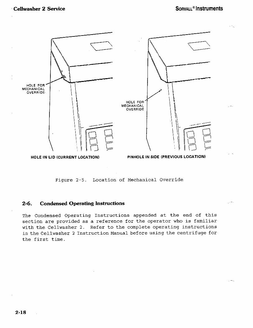
The mechanical override is located on the left side of the Cellwasher 2 .
Depending on your instrument, the override is located in either the
lid or the side of the cabinet as shown in figure 2-5. If the mechanical
override is located in the lid, insert a small screwdriver or similar
object into the hole and push; if it is the small pinhole located in
the side of the cabinet, insert a straightened paperclip and push. The
lid will open.
2-17
Ccllwasher 2 Service SORVALL® Instruments
HOLE FOR
MECHANICAL OVERRIDE
HOLE FOR-
MECHANICAL OVERRIDE
HOLE IN LID (CURRENT LOCATION) PINHOLE IN SIDE (PREVIOUS LOCATION)
Figure 2-5. Location of Mechanical Override
2-6. Condensed Operating Instructions
The Condensed Operating Instructions appended at the end of this
section are provided as a reference for the operator who is familiar
with the Cellwasher 2. Refer to the complete operating instructions
in the Cellwasher 2 Instruction Manual before using the centrifuge for
the first time.
2-18

SO
RV
AL
L®
In
strum
ents
Cellw
asher
2 S
ervice
€0
CO
SB
cs
^5
^»
*c
UJ
C^B
^
UJ
CO
UJ
U
M
E-
C/3
>^ K
l
u 2 s
M
1
-3 -J b
; 0
CM
CE
: b
;
c^
1 ^ M
0
® J
^ < 1 C
O
co
.0 E
0 0
U
<M
0
4-> c 3 0 E
C
O
w
4-*
.2 'E
| &
d
CO
? < •
CM
1-1
• *•> JC
b
o
:=
—^
'S ^ CO
'cL
C
O
'•5
"3
I 0 o>
0 Q.
0
'S
CO
• f—
4
•D
0) 0) Q
- -
"1
•O
3 W
"S
A
§
CO
-
a?
a x?
Q
*-
0 o
s
m
&
"3 .£
CO
~
.•gl
g
« -'
g
2 §
2 1§
^ *•'
£
u
u
w
^ §
s
£ 5£ • C
»3 '"<
• <N
.•2 S
—<
60
^ ^
•«-• 3
C
V
v U
§•
.£ 0
t. •w
0
Q
^
3 ^
CO
'3
£ ^
L.
"
&
£
• •
0^ C
^
W
t- M
C
%
-o
S
°S
'El
£ 5
M
—i
co
t- <a
E-'
t- E
-1 &
to
.£ ^
o
£ ^
C-
-£ l^
• -<
1^ 1
li
^2 S
^^
l-Sg
-Q
^
o
•o
Q-
^ s
« §&
&§
H
en
<u
(o
"S
6 'S
^
•§'•2 •2
2 v
« £
c- i-1
''5 <u
&
•! «" *"
^: •5
c t"
SC
Jh0-
O^b
c ""yco
1 ^i
^-S
-•2^ =
M
E^
—
£. V
) 3
--CO
-CC
O
tlO1-^
c £
^ >>
•*-'"2ott)
toE
c®
t»a» "£*-
cS^g
g.
S-3
'g
£8S-i
£^ §§S
• •
« T
trt
(0 »^
^-<
<-»
= ^
£ i*
-Q
•" b
•^»
o
'o
•O
*- 3
§ 2
«
J <"
1= 5
«
t: •a
>> 0
. °
A
2| t
?
^s s
s E
•-: 1
11
w
S
^ -
S
«B
'S
a> i.2
to
v &
*-£;
--5 =
- v
w
v w
?
i &
5
E
£ J=
.2 S
•^
E
*'''-' £:-o
a?
>.
<y 0)
es""
g^
g
§ ^-s
,5 4)
—
"^ C
Q
- -0
CL
, U
3
bO
<
't0
• •
• T
T
Irt t0
a .C
JS*
tB
"g
o
ii'E
*- 3
<-> 4-1
0)
^2 <"
1 =;
y c
Ctf
®
>> u
'd"' 0)
b
0)
2-0 r1
^ S
*- §
3 U
j|
•§i^
Eg
o
0 ^J
^. 0
a>" •o
U
>
Ctf
"4= •
v
•o
£. c3
CB
.—
004-1
>—
w
a> o
tB
<
C
t. JQ
t^ ^^
a> •c
v „;
o
c *^
CO
= ^
e co
1 1
0 y ^,
M
®
Q
. 0
§3
s ^
^ 1
4-1 c
.
.5 •o
l
o
2l
E-'
'5; p
s
^ t1
< ^M
co
^6
2 £x
a. &
< U
• »
^ 00
Q
... c—
i is
CB
3
~
E
• °?
E.5
"£
.8§° |^
•>^ J5
g
B
Q
o
P
'S
S^
<".= "^
£ S
a, u
c
•o
£| ;.2
•5 eg
0
a »
^j s.^
tf C
tf C
tf w
>>
< 5
< <u
u
E
-1 .
-3 3
•c O
T
£ <
1 S
^ S
C
B
s
£ E
£
c^ &
3
CL
C
O t;
Oi
0
T3
z cc
i i =?
e n
• •
'3 E
f- <^
0 <•)
0 <->
CO
'3
u 2 §00
^3
0; C
O
^S
<U
E
t-
o
<y 0
S
"i 01 §0
ss
CO
•^
in
=
^ <u
?
-s
CB
a
« '"
•^ t-
w
v »
c W
C
D
'" C
O
CO
W
Q
. •O
W
3
*-i *-'
^ ^
1 I
a> <u
0;
ce;
• •
00 0^
c^ »—
•
• c <^
's v '3.
E
0 <u
s ^
11
t3 U
.£ a> C
O
co
4-> 0
§£ rt
0 4->
s s
3 3
^ ^
S
£ E
-" C
L.
CT
(0
• 0
= j C
L
I w
CO
CD
S
e^
i ^^
0
00
2-19/2-20

SORVALL® Instruments Cellwasher 2 Service
Sections. MAINTENANCE
This section describes routine maintenance procedures for the
Cellwasher 2 that should be performed on a regular basis. It is the
customer's responsibility to make sure that these procedures are
followed when necessary. If further maintenance is required, it should
be performed by a representative of DuPont or other qualified service
personnel.
WARNING
Because tampering with high voltage electrical circuits
can cause severe electrical shock/ untrained personnel
must not attempt to test or repair any electrical circuits
in this instrument.
3-1. Inspection and Cleaning
The following preventive maintenance checks and cleaning procedures
should be performed daily. If etiologic or biohazardous materials are
processed in the Cellwasher 2, be sure appropriate decontamination
procedures have been followed before inspecting or cleaning the
instrument.
a. Daily Inspection
Check all sealing surfaces, tubing, liners, and the collecting
ring assembly for cleanliness and good condition. Replace any
worn or defective parts. Replace tubing if it is cracked or
contains accumulated material.
• Inspect the screen on the bottom of the Cellwasher 2 and remove
any obstructions.
• Inspect the stainless steel rotating bowl assembly as follows:
1. Remove the rotor and distributor.
2. Remove the rotating bowl assembly located in the rotor
chamber, directly beneath the rotor.
3 . Inspect the rotating bowl assembly for any sign of corrosion.
Replace if necessary.
NOTE
If inspection reveals that any part of the Cellwasher 2
is not functioning properly, do not use the instrument
until it is repaired.
3-1

Ccllwasher 2 Service SORVALL® Instruments
WARNING
To ensure safe and efficient operation of the Cellwasher
2, all plastic rotating bowl assemblies must be replaced
with a stainless steel rotating bowl assembly (PN 12796).
All Sorvallo Cellwasher 2/ s manufactured prior to February
1984 were supplied with a plastic rotating bowl assembly
which required annual replacement. All plastic rotating
bowl assemblies are more than one (1) year old and should
be removed from service and discarded immediately.
Failure to do so can result in damage of equipment and/
or personal injury.
b. Cleaning
CAUTION
All saline solutions have long term corrosive effects.
Routine cleaning and maintenance (as described in this
section) are essential to ensure safe and efficient
operation of the Cellwasher 2.
Clean the cabinet daily with a damp cloth and mild detergent.
Wipe up spills from the interior and exterior of the cellwasher
whenever they occur.
Remove the rotor, distributor, and stainless steel rotating
bowl assembly and wash them daily with warm water and mild
detergent.
Remove the collecting ring assembly and tubing for routine
cleaning as follows (refer to figure 3-1 for instruments serial
number 8702302 and higher; or figure 3-2 for instuments serial
number 8702301 and lower):
1. If on the back of your instrument, there are tubing clamps
and a T-Connector or a Y-Connector (refer to figure 2-1):
open the adjustable tubing clamp that secures the T-Connector
or Y-Connector in place and remove the discharge tubing.
2. Remove the four mounting screws and step washers fastening
the collecting ring assembly to the lid.
3 . Pull the collecting ring assembly away from the lid, and pull
the discharge tubing up through the wet guard (the molded
black liner).
4. Disconnect the flow tubing from the spray nozzle in the lid
and pull it through the hole in the retainer ring.
3-2

SORVALL® Instruments Cellwasher 2 Service
5. Separate the collecting ring assembly by pulling the
collector ring off.
6. Remove all pieces of tubing, wash with warm water and mild
detergent/ and reinstall tubing.
7 . Wash all components of the collecting ring assembly with warm
water and mild detergent.
TO FLOW
DETECTOR
STEP WASHER
MOUNTING
SCREW
TO WASTE
CONTAINER OR
T- OR Y-CONNECTOR
Figure 3-1. Exploded View, Collecting Ring Assembly
(Serial Number 8702302 and higher)
3-3

Cellwasher 2 Service SORVALL® Instruments
NOTE
Make sure the nozzle for the discharge tubing on the
collector ring will align with the groove in the wet guard
when the assembly is reinstalled in the Ceilwasher 2.
8. Reassemble instruments serial number 8702302 and higher as
follows:
a. Place the retainer ring on a table or bench so that it
rests on the smaller opening, and work the 0-ring seal
around the outside of the large opening until it is fully
seated in the groove of the retainer ring. Then, place
the collector ring so that it rests concentrically over
the 0-ring seal and press firmly into place. Then proceed
to step 10.
9. Reassemble instruments serial number 8702301 and lower as
follows:
a. Place the retaining ring on a table or bench so that it
rests on the smaller opening. Lay the vinyl seal
concentrically on the upper edge of the retainer, and
gently place the collector ring on the seal so that it
also rests concentrically.
b. Place the thumb of each hand on top of the entire
assembly, slip your fingers beneath the lip of the
retaining ring, and begin pressing the two rings together
evenly all around the lip. Lift the entire assembly and
continue to squeeze the rings until both edges are evenly
together.
c. Examine the assembly: at no point along the edge should
more than 6_mm (0.25 inch) of the vinyl seal protrude.
If it does, open the entire assembly and realign the seal.
Once the vinyl seal is centered, any excess less than 6_mm
may be trimmed off with a sharp knife or blade. Then
proceed to step 10.
10. Reinstall the collecting ring assembly in the lid of the
Cellwasher 2 by reversing steps 1 through 4 of this
procedure.
NOTE
When replacing the four mounting screws, make sure the flat
side of each step washer faces the screw head.
3-4

SORVALL® Instruments Cellwasher 2 Service
Figure 3-2. Exploded View, Collecting Ring Assembly
(Serial Number 8702301 and lower)
3-2. Tubing Replacement
If tubing is damaged and must be replaced, install tubing supplied in
the Tubing Replacement Kit (PN 12977) following the instructions
supplied with the kit. Refer to paragraph 9-1 for a copy of the tubing
installation instructions.
3 - 3. Cellwasher 2 Preventive Maintenance Procedure
NOTE
Before starting the preventive maintenance procedure, be
sure the instrument is functioning properly.
3-5

Cellwasher 2 Service SORVALL® Instruments
a.Visually inspect the Cellwasher 2 for cracks/ saline leaks and
corrosion (including the stainless steel rotating bowl, saline
detector, motor, pump and pump motor).
b. General Inspection
Inspect and/or check the following:
• Touch Panel - check all touch switches for proper function.
• Nozzle Assembly - check for cracks, leaks and obstructions.
Drive Ring - check for elongated holes/ softness and loose set
screws; check proper height dimensions.
Drain Tray - should be clean with no obstructions in drain tube
and drain tray gasket.
• Motor Mounts - check for tightness, separation and softness.
Lid - inspect front seal and mating surfaces.
Hinge and Torsion Bar - check for proper function.
Collecting Ring Assembly - check condition of seal.
• Motor and Decant Coil - check for resistance, coil concentricity
and saline deterioration.
• Electrical Connections - check for looseness and worn wires.
• Pump - inspect for rusty or noisy rollers.
• Saline Detector - inspect and check function.
• Tubing - check all tubing for cracks and/or obstructions.
c. Inspect all tubing; replace if necessary.
d. Lid Latch
1. When the lid is closed, the latch engaged, the lid light not
illuminated and the instrument operating, the lid can not be
opened.
2. With the lid open and the lid light illuminated, the instrument
will not run except in the agitate prime mode.
3. Upon completion of a run, the lid can not be opened until the
lid light illuminates.
3-6 Rev. 11/90
SORVALL® Instruments Cellwasher 2 Service
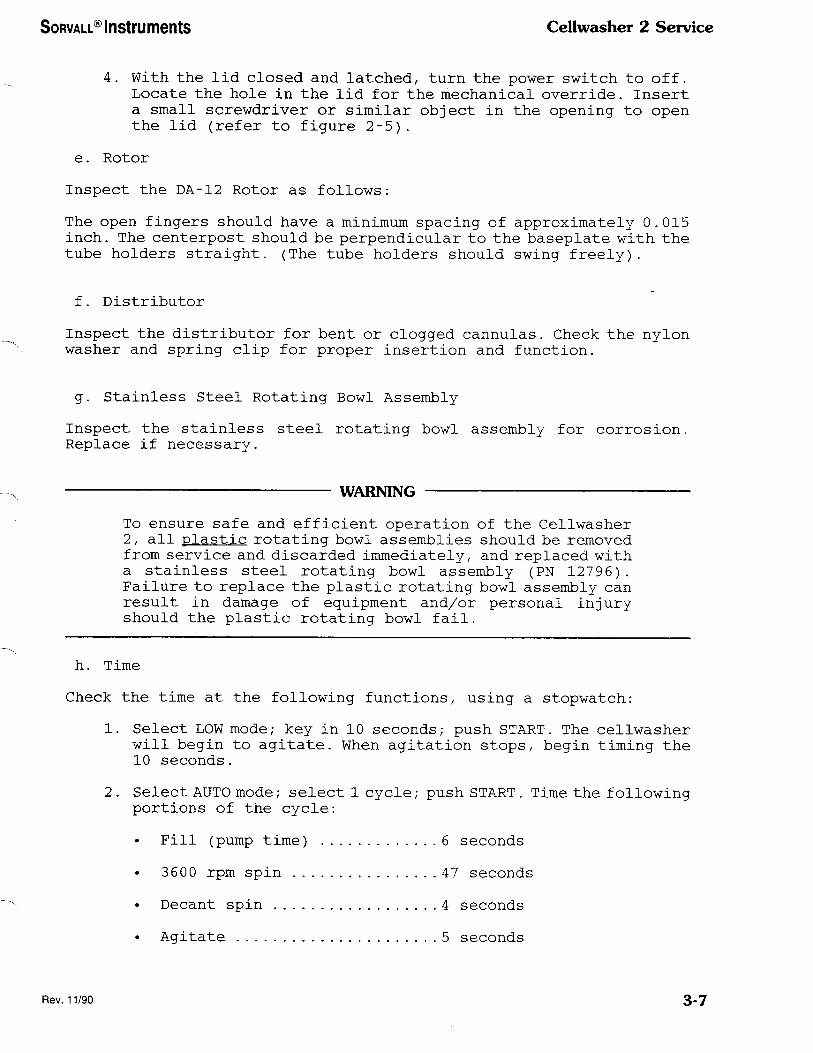
4. With the lid closed and latched, turn the power switch to off.
Locate the hole in the lid for the mechanical override. Insert
a small screwdriver or similar object in the opening to open
the lid (refer to figure 2-5).
e. Rotor
Inspect the DA-12 Rotor as follows:
The open fingers should have a minimum spacing of approximately 0. 015
inch. The centerpost should be perpendicular to the baseplate with the
tube holders straight. (The tube holders should swing freely).
f. Distributor
Inspect the distributor for bent or clogged cannulas. Check the nylon
washer and spring clip for proper insertion and function.
g. Stainless Steel Rotating Bowl Assembly
Inspect the stainless steel rotating bowl assembly for corrosion.
Replace if necessary.
WARNING
To ensure safe and efficient operation of the Cellwasher
2, all plastic rotating bowl assemblies should be removed
from service and discarded immediately, and replaced with
a stainless steel rotating bowl assembly (PN 12796).
Failure to replace the plastic rotating bowl assembly can
result in damage of equipment and/or personal injury
should the plastic rotating bowl fail.
h. Time
Check the time at the following functions, using a stopwatch:
1. Select LOW mode; key in 10 seconds; push START. The cellwasher
will begin to agitate. When agitation stops, begin timing the
10 seconds.
2. Select AUTO mode; select 1 cycle; push START. Time the following
portions of the cycle:
• Fill (pump time) ............. 6 seconds
3600 rpm spin ................ 47 seconds
Decant spin .................. 4 seconds
• Agitate ...................... 5 seconds
Rev. 11/90 3-7
Ccllwasher 2 Service SORVALL® Instruments
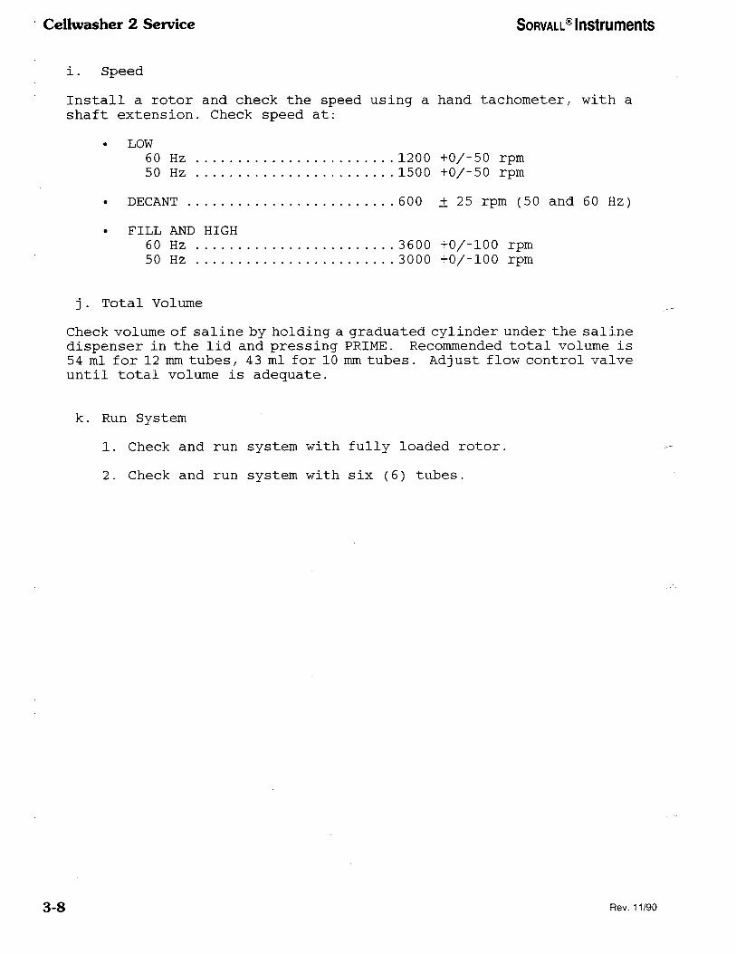
i. Speed
Install a rotor and check the speed using a hand tachometer, with a
shaft extension. Check speed at:
• LOW
60 Hz ........................ 1200 +0/-50 rpm
50 Hz ........................ 1500 +0/-50 rpm
• DECANT ......................... 600 ± 25 rpm (50 and 60 Hz)
. FILL AND HIGH
60 Hz ........................ 3600 +0/-100 rpm
50 Hz ........................ 3000 +0/-100 rpm
j. Total Volume
Check volume of saline by holding a graduated cylinder under the saline
dispenser in the lid and pressing PRIME. Recommended total volume is
54 ml for 12 mm tubes/ 43 ml for 10 mm tubes. Adjust flow control valve
until total volume is adequate.
k. Run System
1. Check and run system with fully loaded rotor.
2. Check and run system with six (6) tubes.
3-8 Rev. 11/90

SORVALL® Instruments Ccllwashcr 2 Service
Section 4-1. MECHANICAL THEORY
This section describes the mechanical functions of the Cellwasher 2.
4-1. Controls
The Cellwasher 2 control panel features touch pad speed switches and
function selectors, a digitized electronic timer/ and the choice of
either automatic or manual operation. Refer to Section 5, Electrical
Theory, for detailed operation.
4-2. Flexible Drive Mount-ing
The motor and rotor combination is vibration mounted using a three point
suspension system. This arrangement isolates minor tube imbalances
from the instrument.
4 - 3. Cabinet
The cabinet is cast from structural foam in one continuous integral
piece for strength and a pleasing cosmetic appearance. The lid is opened
by pushing the LID button to release the solenoid at the completion
of a run; a torsion bar built into the structure raises the lid.
4-4. Air Flow
Cooling air is drawn in from underneath the cabinet/ taken up through
the stainless steel screening, and circulated by the motor fan through
and around the motor and components. The source of air supply must never
be obstructed by objects placed in front of or near the base of the
instrument.
4-5. Motor
The motor has been specially wound to operate at either 3600 (60 Hz),
3000 (50 Hz), 1200 (60 Hz), 1500 (50 Hz) or 600 rpm depending on operator
selection or program sequence. Dynamic braking is accomplished by
applying current to the motor to retard its rotation.
4-6. Safety Latch
When the lid is closed on the cabinet, a solenoid plunger automatically
penetrates the lid, thus securing it. To make sure the lid has been
closed and the plunger is in place, two signals are generated indicating
whether or not lid-locking conditions have been met before permitting
the Cellwasher 2 to operate. Two hall effect transistors have been
placed on the lid latch PC board to ascertain that the lid is closed
and that the plunger is extended in position. The lack of either signal
will prevent operation.
4-1

Cellwasher 2 Service SORVALL® Instruments
4-7. Saline Pump System
The quick load tubing pump offer the advantages of a unique, easy method
of loading the tubing. The pump uses stainless steel rollers and has
a clear plastic housing, both of which offer excellent protection
against corrosion. The pump is driven by a shaded pole AC drive motor
gear reduction head to minimize pump tubing wear.
4-8. Flow Detector
This device is placed between the saline pump output and the
distribution nozzle to detect interruptions in saline flow. The
detector is mounted vertically so the saline causes an upward
displacement of a magnet in the path of the saline stream. When saline
flows properly/ a magnetic reed switch is open and no signal is
generated. When saline flow decreases, the magnet displacement is
minimal and the reed switch is in the ON position for signal generation.
This signal warns the operator of insufficient saline supply to the
instrument.
4-9. Flow Control Clamp
The flow control clamp restricts the flow of saline through the tubing.
4-10. Motor Antirotation Clutch
This clutch is mounted on the bottom of the drive motor and allows one
rotation only with no back lash. Roller bearings wedge themselves up
an inclined plane when the rotor is turned in the opposite direction,
preventing further rotation of the motor.
4-2

SORVALL® Instruments Cellwasher 2 Service
DUPONT CELLWASHER 2
Preventive Maintenance Checklist
SN
ACCOUNT
DATE
SR
OK ADJ
D D
D D
D D
D D
D D
D D
D D
D D
D D
D D
D D
D D
D D
OK ADJ
D D
D D
D D
D D
D D
General Inspection
Touch Panel
Nozzle Assembly
Drive Ring
Drain Tray
Motor Mounts
Lid
Hinge and Torsion Bar
Collecting Ring Assembly
Motor Decant Coil
Electrical Connections
Pump
Saline Detector
D D Rotor Bowl Assembly
D D Distributor Inspection
D D Inspect Tubing
D D Replace if requested
Lid Latch
Cannot be opened when instrument is
running.
Centrifuge will not start when lid is up.
Cannot be opened until light illuminates.
Mechanical override.
D D Time
Rll (pump time)
3600 rpm
Decant
Agitate
9 sec
47 sec
6 sec
5 sec
a D Speed
Fill and low
1200+0/-50 rpm
Decant 600+/-25 rpm
High3600+0/-100rpm
D [3 Total Volume
12mm
10mm
D D Fill Level
12mm 3/8" or 0.7 ml
10mm 7/16" or 0.7 ml
D D Run System
D D Full Rotor
D D Six Tubes
Rev. 4/96 3-9/3-10

SORVALL® Instruments CeUwasher 2 Service
Section 5. ELECTRICAL THEORY
5-1. System Description
a. General
AC power enters the instrument through the voltage selecting the RFI
filtering (CORCOM) connector, which is at the back of the instrument.
The connector contains a fuse.
The electronics system consists of a +5V power supply and 4 printed
circuit (PC) boards, namely: the touch switch panel / the microcomputer,
the triac-interface, and the latching PC boards. The first three boards
reside in the electronics enclosure to the front of the instrument,
while the latching board is part of the latching mechanism screwed to
the instrument cabinet. A 20-pin flex cable soldered to the touch switch
panel PC board mates to a connector on the microcomputer board. A 16-
pin interconnecting ribbon cable mates to sockets on both the
microcomputer and interface PC boards. Power to and from the
electronics enclosure leaves via a 16-pin molex connector soldered on
the interface board and a connector mounted to the kydex cover housing
the electronics. For more detailed information/ refer to figure 5-1,
System Schematic and figure 5-2, Wiring Diagram. The power supply is
composed of a 115V: 10 VAC center tap transformer, a full wave rectifier,
a filter capacitor and a 5V regulator — all mounted on the instrument
chassis. An unregulated 14 VDC ± 10% should flow across the capacitor.
b. Touch Switch Panel
The touch switch panel contains 25 SPST normally open switches. Twenty-
four of the switches are arranged in a matrix of 4 rows by 6 columns.
The 6 columns: MODE, CYCLE/ TIME 1, TIME 2, TIME 3, and COMMAND are
each scanned by the microcomputer. Data from each column is paralleled
and read by the microcomputer through lines A/ B, C, and D. Because
of the sequential nature of scanning, data can only be received from
the particular switch column being scanned. The one remaining switch
(LID) is independent of the matrix arrangement, and is the only switch
with audio feedback. This switch is in parallel with the lid indicator
and in series with the open line which activates or deactivates the
latching mechanism.
The touch switch panel also contains 7 light emitting diodes (LED's),
the state of which are controlled by the microcomputer through lines
labelled START, STOP, AUTO, HIGH, LOW, CHECK/ and LID.
5-1/5-2

~~~~~~~~ Instruments ~~~~~~~~~~ 2 Send~e
LINE CORD
115V ~~H~~~O~~~20V 50 H~~
~P~~————~ 1 ~ ~~
~~~~
PUMP p~~ ~O~OR
~~50
H~~~~~~~~~~
~~~S
~
LATCH 1~~~~~~~~~~~~~
12792
————~~~
045~7
~~~
~~~~~l ~~~~~~2
~~~~~3~~
~~7
FLOW ~~~~~
~
~~ ~~~~
~~~~~~~
~~~~~~~~~
~~~~~~~~~~~~~~~~~~P/M
0454~3
~~ P~
~~
~~~
L2 ~~~~~1
~~~~~
CO~~E~~~~R VOLT AC
AM~ CAB
P/M 0457
J~~
~~~~~~~~~~~~~~ H~ ~~~
~~~~~~ ~~~ 1 ~l~ ~~ ~~~~
~~~~~~~~
~~
~~~~
~~~——
~~~OID
~
~~~
+~~2) ~~~~3?
~~~1>
~
~~~~~~
~~~~~
~~~~~~~~5
~~~~~~~
~,J
~
A5S~~~ ~~
~ ~~~~
~
~
~
~3~D~
~7
~~~~~~~
~~~~~~~~~1
~~
1
~~
~ ~~
~ 2345~~~7&~l0 ~ ~~ ~~~ ~~~ ~~ ~~ ~~ ~s~ ~ ~
Pl4 -
~~~C~
~~
—
—
-
S PI~ J~~ P~~
~~~~4
~~~~~
~~5~~
~~~~~
~~7~~~
• ~~ C~
~~
1
~~
1
~~
~5
~~~~~~~4 ~~2~~+
~3~
~~~~~
1 1
2 ~———————
3
S4
T81
~~~
~ ~~
~~
~~~~ ~3~
~~~~~
~ ~~~
~~
DECANT COIL
————————————————————~3~———————————— ~~
——————————————————————————~~~~~—————————~~~~~~
~ ~..... ~~ ~ ...
~ ~~~
~ ~ ~~~~~~~~
~ ~~~~~~~
CAPAC1TOR
ASSY. ~ ~~P/N 04568 60HZ ~
~~P/N 0451050~Z -
~~~~~~
~~~~~
~~~~
~~
i,
~~
P~~P ~~
..~ ~~~~ ~~~~~~~~~~~~
~~
~~ LATCH~D ~~~~~
S~~ LATCHED
~~ ~J<
OP~~~~~~~ ~~
~~~~~~ ~~
5~00 ~
~~~~~~~~~~—
~~~~ ~
~~~~~~ ~~~ 1
TB1
~
S~ITCH A~SY ~~~~~ ~~~~~ ~ ~~~ ~~~~~ — P/N 045~0
~~~~~~~~~
~~~~~ ~
~~~ ~~~
1 3 AC
~~ ~~~ ~~ | ~IO~~AC ~~
~~ ~ ~~~ 5 ~ ~~~~~A~ ~~ ~ ~1
115 ~ —————~ — ~~~~ - ~8~~~
~~~——~~
~~~ ~~~ P~ ~~ PI
~~~~ ~~<
~~~~ ~~~
~~~~~~~~~ ~
~ 1 ~~~
~~CANT ~~~ ~~
~~~~ ~~~~~~
~~~~~ ~——~ L~~—~ ~~ P~~
~~~~~O-~~~~ ~~ ~~
ST~P ~~~~~~
T2
~~0
~
~
~~~~~~~~~~~~~~~
~~0 0 C~~ E
~~ ~~~~
C~~22
0 ~ P4
~
~IO ~17
~1— 1
~0~ IR
~~
~~~
~~~~~
~
~~~
~
—~
~~~
~~~
>-~~~
•
~4
~~~~~~
l5~——
~~~
6~~~
7~4~~5~~~2~~~~~3~~~~~4~——
~~~~
~~~~
a~~~~
~~~~~~
2~~~
•o~~~
~~~
~
MOTOR
~~~~~~~~~~~~BO~~D
P/N 04834
~LS~ ~ - ~
~~~~~~~~~~~~~~
~20 P20 P2
~~~ ~~~~~
~~~~~~~
~~~~~~
~~~~~~
~~~~7~~
~~~~8~~~
~~~
~~~~~~~
~~~~~~~~~~~5~~
1 ~ ~~~~
~~~l5~~
~~~~l6~~
~~~~ P
~~«~~~
~~~
~~~~3~~~
~~~~~4
~ ~~~~~
~~~~~~~~
~~~7~ 1 ~ ~ ~~ ~~~~~~ ~ ~~~~1
~~~~~
~~~~~
~~~~~~~~
1 ~~~ ~~~~
...I ~~ ~~~
~ ~~~~~ 151 LATC~ED
~~~~ ~~~~~
~~~ |
~~~~~—————~
~~~~~~~~ASSY
~~~~04845
~~~~~~~~~~~~~~N
~~7547
~~ p 3~00
BRA~~~~
~~~~~~
+5V
~~~~~
~00
6~D
PUMP
~~0
~~~
+5V
45V
~LO~
D~~~~ MOTOR S~E ~~~~~~ ~
3
~~~
~~4~4~
~~~ ~~ 1
~~~~~
~~~~ 1
~~~~~~~~~~~~~
J~1 <l~~~
<~~~~<~~~~
~~~
~~5~~~~~<6~~
<7~~~
<a~~
~~~~<~~~~~
<~~~~~~<.~~~
~~~
<15~~~~<16~~~
~5
~~ 1
~~~ ~
~ ~ ~
~~6~~
~~~~ ~ ~ 1 >1~~ ~
~~~~~~BOAR~~P/M
04639
MIC~O - COMPUT~R
BO~R~
P/M 04S27
~~~~~~~
1,~OR 6~~FOR 5~
~~ H~~ ~~~
~~ ~
J5 P
~~~~~~~
~~~~~ ~~~~
~,~ ISC6~~O~
~~~~~~~
~ ~~ ~
~~~~~4 1 ~ STOP
~~~~~~~~~
~~~~
~~~~1~~~
~~~~11~~
~~~l~~~
~~'~~~
1 ~~~~
+~~IS~~
t ~\t~~ ~
~~~~\~~~~~
1 ~~~~ ~~~~~~
~ ~<
~~
~~~~ A~~~~~~ ~~
5 ~~3~~~~El~
SC~(~~~~
S~5~~~£3
START
AUTO
~~~
~~
LID
CHEC~
~A ~~~~~~
C
5
4~~~~~~~———~ LID 5~~
;~~. USE P/N 12975 ~Y,~SE P/M ~12976
~~~~~
~~~UCH ~WITCH PA~~~~~
P/M 0450~
~~ ~~~~~ ~~~ ~ - Figure 5-1.
System Schematic, Cellwasher 2
5-3/5-4
Rev. 4/96

~~~~~~~~ Instruments ~~~~~~~~~~ 2 Service
POWER ~~RA~S¬ FORMER
~~~~12345
~ ~~ ~ ~~ ~
~ ~~~ £ ~~ ~~~~~ ~ ~ ~~ ~
~~~~~~~~~ ~?~~~ ~~~ ~~ ~O ~~ ~~ ~ ~ ~ ~ ~
~~~~~~~
I ~~~~~~~~ I
| ~~~~~~~~~~~~~~ ~OR ~30V
~ 50 ~ ~~I ~~2 I
AC |~
~
~00
230 11 ~~
~~
0
~
~~~
~
~~
|.~~A~P ~~~~0-S~O
~~
~~~~
~
~
~ 5
~~~ 04574
~~~~ A~S~ VOLTA~E AN~ ~~~~~
Jl5 P~S
~~~)Jl~-l. ~~18~J1~-~
-~9)JIZ-3 ~~~0~~1~-4 ~~~~T81-1 ~~2~~Bl-~~
-~~)T6l-A
~~ ~~~
~~~~~~~~~~~~J17-D-
~~~ ~~~~~ ~~~~~~ 0~~~~~~, ~6~~ ~ ~~~~~~~~~~ ~~~~~~~ ~~O~~-~~~~~~TIOM~~~~~ B)SPI~ ~~~~~~~~ ~~~~~~~~~
~~~~~ ~~~~~~~~~~~~~ ~~~~~ ~~0~~ ~~~ ~~~~~~~~~ ~~~~~ ~~~~~~ ~~~~~~~~~~~~~~~ ~~~~~~~~~ ~~~~~~~ P~~~ ~~~~~ ~~~~~~~~ ~ ~~~~~~~~~~~~~ ~re~~ ~~~t~~~~~~~~~~O~
~~~~ ~~~~~~~7~ ~~~~~~~~~~ ~~~~~~~~
Figure 5-2.
Wiring Diagram, Cellwasher 2
5-5/5-6
Rev. 4/96

SORVALL® Instruments Cellwasher 2 Service
c. Microcomputer PC Board
The microcomputer PC board contains all of the system's intelligence.
In response to input of commands from the touch switch panel, the
microcomputer makes decisions as to which indicator, seven-segment
display, coil or motor to turn on or off. The components on this board
are located and described in figure 5-3 and table 5-1 and indepth
electrical information is given in figure 5-4, Microcomputer PC Board
Schematic.
The 3870 microcomputer (Z4) is a one chip combination of processor and
memory, with four I/O ports of eight bits each.
^
Figure 5-3. Microcomputer PC Board,
PN 04527, Revision 4
5-7

Cellwasher 2 Service SORVALL® Instruments
Table 5-1. Microcomputer PC Board
Component Identification (PN 04527 Revision 4)
(key to figure 5-3)
Component
Designation Description
Manufacturer/s
Order No.
J3 Socket Integrated Circuit
Dip, Solder Tab, 16-pin
Circuit Assembly
Corporation
#CA-16S-10SD
J5
Rl, R2,
R3
R4
R5
R6
R7, R8,
R9, RIO,
Rll, R12,
R13
Connector, Flex-Strip Cable,
20-position
Resistor, Carbon Comp./ 5%,
1/4 W, 1k OHM
Resistor, Carbon Comp./ 5%,
1/4 W, 6.2k OHM
Resistor, Carbon Comp., 5%,
1/4 W, 47 OHM
Resistor, Carbon Comp., 5%,
1/4 W, 4.3k OHM
Resistor, Carbon Comp., 5%,
1/4 W, 100 OHM
T&B Ansley
#742-20
Cl Capacitor, Ceramic Disc,
.1 MFD, 50 WVDC
Centralab
#CK104
C2 Capacitor, Electrolytic,
Aluminum, Radial, 10 MFD,
25 WVDC
Illinois
Capacitors
#106RLR025M
C3
C4
Capacitor, Ceramic Disc,
.01 MFD, 500 WVDC
Capacitor, Electrolytic,
Aluminum, Radial, 47 MFD,
35 WVDC/ -10%, +50%
Sprague
#19C241A2
Sprague
#503D476F035NB
C5
Zl
Capacitor, Metallized
Polyester, 100 VDC, 1.0 mf
Integrated Circuit, Quad
2-Input Positions, Nand Gate
Mepco/Electra
#C280AH/PIM
Texas Instruments
#SN7400N
'Indicates standard component available through most suppliers.
5-8

SORVALL R
Instruments Ccllwasher 2 Service
Table 5-1. Microcomputer PC Board
Component Identification (PN 04527 Revision 4)
(key to figure 5-3) continued
Component
Designation Description
Manufacturer/s
Order No.
Z2, Z5
Z3
Z4
Z6
Z7
Z8
Z9
Z10, Z19
Zll
Z12
Z13
Z14
Z15, Z16,
Z17, Z18
Yl
Integrated Circuit/ High
Voltage, Output/ 14-pin/ Dip
Integrated Circuit, Digital
Monostable Multivibrator
Gates
Integrated Circuit, Hex-Non-
Inverting, 3-State Buffer
Integrated Circuit, Darlington
Transistor Array
Integrated Circuit, Cos/Mos
Hex Buffer Converter,
Inverting Type
Resistor, Network, 8-pin Sip
2k OHM, 2.1 Watts
Integrated Circuit, General
Purpose High Current
Transistor Array
Resistor Network, 14-pin Dual
In-Line Package, 390 OHM
Resistor Network, 14-pin Dual
In-Line Package, 47 OHM
Light Emitting Diode, 430 inch,
7 Segments, Red
Crystal, PC Type, 4 MHZ
Texas Instruments
#SN7417N
Texas Instruments
#SN74121N
Microcomputer Programmed Memory
CW-2 04555
CW-2L 04931
Integrated Circuit, BCD to 7 Motorola
Segment Latch/Decoder/Driver #MC14511B
Integrated Circuit, BCD to Motorola
Decimal Decoder/Binary to #MC14028B
Octal Decoder
Motorola
#MC14503B
Sprague
#ULN 2003A
Motorola
#MC14049BCP
Dale Electronics
#MSP08C01
Sprague
#ULN 2082A
Alien-Bradley
#314B391
Alien-Bradley
#314B470
Hewlett Packard
ftHDSP-3733
Crystek
#CY3A
Rev. 4/96 5-9

Cellwasher 2 Service SORVALL® Instruments
Table 5-1. Microcomputer PC Board
Component Identification (PN 04527 Revision 4)
(key to figure 5-3) continued
Component
Designation Description
Manufacturer's
Order No.
BZ1
X24
XZ15, XZ16,
XZ17, XZ18
DS1, DS2
Buzzer, PC Board Mtg,
Socket/ Integrated Circuit,
Low Profile, 40-pin
Socket, Integrated Circuit/
Elevator, Bifurcated
Contacts, 14-pin
Lamp, Indicator, Yellow,
5.0 Volts
Projects
Unlimited
#X30W05
Texas Instruments
#C84-40-02
Aries
#14-8620-10
Penn Keystone
#7561-4-5
TP1, TP2 Terminal, Swage/ 2 Turrett,
Brass, Silver-Plated
H.H. Smith
#2018C
5-10

~~~~~~~~ Instruments ~~~~~~~~~~ 2 Service
FL~ ~ ~~~~~~~~ 1~~
~1 ~~~~~~~
~ ~Ar~~£~
D~C~N~
~~~~~
~00 ~~~
1~00 ~~~
~~00 ~~~
PUMP
1~~ ~
~~~~~
NOTES
~3 R~ ~ ~~
~ ~ ~~
~ ~~ I*
~~~~~]~~
~5~~~~
~ ~ 1
1
3)————
~~————
6~————
5~~———
~ ~ ~ ~
- ~
~~~ \ ~ ~~
~~4~+
~2~~
~~ ~
• ~ ~ ~~~~——
~~~~~~
~~I~~
~~~~~~~~~p~c
~ 0~~L ~I ~~~
1
~~~
7
~~ S
O~~~~~~~~
~ ~~~~~~~~~~
~~
~R3 ~~~ 7~1~~~
~~~————
~ n ~~
11~~
~~404~
~~~
~~ - ~10
~~40~9
~~40~9
~ 40~~~
~~~~~~~~~~~ ~~~ ~~ ~~~~
~~ ~~~£ I~~~
~~~~~~~~~~
~
0
~~
~ ~~~~~~ ~P~ ~~ ~
~~~~
~~~~ ~~ ~~~~ ~~
~~~——————— ~~~~~~
~~~~~
~~ ~~17~17 ~~~~~—————————~
~~ ~~~~~~~————s~~~~——————
~ ~~~ 7~/7 ~~—————————————
~~7~/7~~1 —————~~————————
~~ ~~ 74/7 ~~———————————
~~~7~/7
~5~~
~ ~~~ ~~~~
+5 ~~~~~~~~~
~~~~~~~~ ~ ~~ ~~~~~~~~~
~ —~~~~~~
1
~~ ~~ ~ ~
,~~
~~~~~~ ~ —16~1 )~~~~~~
~~~ ~~
~~~ ~~
~~~~~~~~~~ ~7~~~~~~~~~~
~
~
~~ ~
~3 ~~~4111 4
11
~~1~~~~
C3 ~0
1s] ~~
W 1
~~~
f~
~~
~
31
3~
~1
1
- 2
7
~~~~
4~
~~~
~
~ ~~
~ 7 ~~~
6
~
~ \~S
7
1
~~
~~~~
~~~~~PI~
~~~~
~T~~2
TEST 1 ~
~
* +~~
~ ~~~ • ~4.3~
~ 7 ~
~~4
3
2
~~~~~
~7
~~5
4
~~Z
~~I~
~~ ~~~~ n ~~~~~~~
~e S~~~
If STOP
6 WO
5 HI
4m
3 ~~~~
~ ~4 ~~~ 77
~3~ ~5 ~6 ~7
~~ - ~
~~
3
~911~~~
~ ~~
40~~~~~~~~
1~74/7 ~~ —————————~~
~~ ~~ ~~7 ~s
~~ ~
~~~~—— ~~~~
~
~1~
~
~
- ~
5
2 ~ 7
~~ ~~ ~~ I~
9 7
~14
~1~
A
~~~ ~6
~~~4611~~ a
~~~~ ~~
~~11
~~~ ~
~ ~~C ~
~ ~~~~ ~
~7
lo~s
4
5
~~7
S
9
~
~~~~~ ~~~
t8 ~~~~~
~~
~
IS ~~ 11 10 ~ ~ 14
1
~ 14 ~ ~~~
1
~
7
~
~
5
~0 ~ 4 Z
~~~~~~
~
~~ ~~~
~~~~~~
~
~~
P~
~
~~ ~SOW
~~ ~~o~~
~~ 4o~ ~~~~
S ~
~~ ~ ~~ >~
~~o...~o~ ~ ~ ... ~~
~ ~ ~ 4 5 6
~
~~~~
~~3 ~~~ ~~ ~~~ J5
~~~~~~~I~
————————————~~~ ~~~~~~~ 1——————————————————————————————————————————————~~ ~ ~~~~~
~ ~~ ~ ~ ~~ ~~7
10 1~ ~ ~ ———————————————~~~~2———————————————————————————————————————————————————————~~~ ~
~~~ 100
~~~ 1~0
~~~~~~~
~~~ ~~~~ WO~
~I?
~~~~
~~~~
5~~~
~~ ~~~ ~~ ~~ ~
~~~——————————————————————————————————————————————————————————————————————————~/~~~
~~~~~~~~~~ 1 ~ - ~~~~~ ~ 1~
~~~~
~ ~~ C
~ ~~~ ~~
~~~
~~~~~~~~~~~~~~~~~~~~~~
~~~~~~~~~~~~
~
~———
~~ ~~~ 14 IS 1~ It
10
———————————————————————————————————————————————————————————~———————————~~~5 ~~~,
(~~~~~4~ ~~ ~ ~—— ~~~~
~~~~ ~~~~
w
~~
~~
————————~~ ~~~~~~~~ ———————————————————————————————————————————————————————————————————~ ~~ ~~~~~~ ~~
~———————S~~~~~~~~~———————————————————————————————————————————————————————————————~ LID
+5~~ 1 ~/~ ~~ ~ ~
~ ~~~ ~ ~ ~ ~ - ~~~ - -
~~ 1 ~2 ~~~ 3 ~ ~ ~ ~ ~ ~
~ ~//...~b ~~~~~~~~ 13~~~ ~~~ ~~ ~ Is I~~ ,~ ~~~ ~~ ~~
~~ ~
~ ~
* ,0
~~~~ ~ ~~~~~~ ~~ ~~~ ~ ~~ ~~ ~~ a
~~~ 7 ~ ~ ~~~~ a ~~~~ ~ ~~ a ~~~~~~~
~ ~~ 4 ~o ~~~ 5 ~ ~
~ ~~~ ~ ~~ ~~~ 7 37~~ 7 ~~~~ 7 37~~
~~ ~—~~~~~~~~ ~~~~ ~ ~~~ ~~~ ~~ ~~ ~ ~~ - ~~~ ~ 10 1 13 ... ~ 9 ~~ ~~ ~~ ~~ ~~ ~~
~~~ ~
~~ ~~ ~ 3 ~~| ~ ~~~~~ ~3 ~~1 ~~ ~S~~ ~ .1———1 ~~——1 ~———I
~~ ~~
~~~ D~~~ ~~~~~~ ~~~~~~~
~~~ ~ ~~~~~ 1 1 ~ ~ ~
A~~~~~ ~~ ~ ~~J
S~LINE
~~~~~~
—————————————————~———~———————————————————————————————————————————————————~——~~~/~ LID ~~
~~~~~ ~1~~~ ~ (3~9
—————————————————————————————————————————————————————————————————————~6 5~5 C
~~~————————————————————————————————————————————————————————————————————~~~3 ~~~ ~~ ~049
~ ~~ ~~
• ~ ~~T ~~
~~~——~~~ ~5~~
~~~~ ~~~~
~~~~~~ 5-4. Schematic,
Microcomputer PC Board
(~~~£)
5-11/5-12

SORVALL® Instruments Cellwasher 2 Service
d. Hardware
Six bits of port 0 are dedicated to the LED indicators of the touch
switch panel. The hex buffer gate (Z5) serves to sink current from the
LED's. The seventh bit is used to turn on the alarm lamp via one of
the transistors of Z9 . The remaining bit is used to enable or disable
Z8.
The common cathode 7-segment displays (Z15-Z18) are multiplexed.
Segment data comes from the upper four bits of port 1, through the BCD
to seven segments latch-decoder/driver (Z6), and the high current
(source) transistor array (Z12) . Data from the lower four bits of port
1 act as the display digit selector; through the BCD to decimal decoder
(Z7) and the high current (sinking) transistor array (Z9).
Port 1 is not entirely dedicated to the displays because of the
multiplexing arrangement. The lower four bits of port 1 (used to select
display digits) are also used to scan, via Z7, the six columns of the
touch switch panel. The data from the touch switch panel A, B, C and
D comes in through the noninverting three-state buffer (Z8) and reads
into the microcomputer through the upper four bits of port 1. Z8 is
enabled only when its data is being read in. The 10K resistor pack (Zll)
act only as pullups. In port 4, bits 0, 1, and 7 are not used. Bit 6
is used to light the saline lamp via one of the remaining transistors
of Z9. Bit 5 is used to control the lid indicator and to activate the
door open circuitry of the interface boards. For more current
capability, this line uses a transistor in Z9 as a buffer. Besides going
to the lid indicator, the transistor output goes to lid switch 1 on
the front panel and returns at lid switch 2 . Lid switch 1 and lid switch
2 are on the two legs of the lid switch which completes connection to
the open line for latch solenoid control when it is pressed.
An audible signal occurs when the sensor-touch control buttons are
being operated, when the ALARM button is activated, the end of a run
has been completed, or if the saline level is inadequate. A monostable
multivibrator (Z3) controls the duration of the audible signal (beep)
through C4 and R6. These components presently select a duration of 141
milliseconds. Z3 is controlled by a negative going voltage transition
from bit 4 of port 4.
The saline flow detector is a normally closed switch and is open only
when saline is flowing. Two wires are connected to the switch contacts ;
one is connected to ground and the other is connected to "flow" on the
microcomputer PC board. A high on this line indicates good saline flow
as read in by bit 2 of port 4.
Only bits 0 through 5 of Port 5 are used. Their function is to enable
or disable the triacs on the interface PC board that in turn switch
power to different components in the system.
5-13
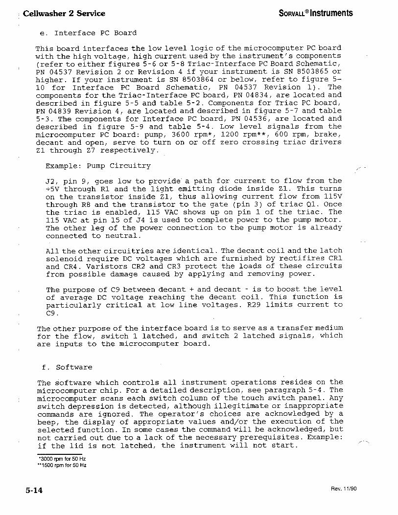
Cellwasher 2 Service SORVALL® Instruments
e. Interface PC Board
This board interfaces the low level logic of the microcomputer PC board
with the high voltage, high current used by the instrument's components
(refer to either figures 5-6 or 5-8 Triac-Interface PC Board Schematic,
PN 04537 Revision 2 or Revision 4 if your instrument is SN 8503865 or
higher. If your instrument is SN 8503864 or below, refer to figure 5-
10 for Interface PC Board Schematic, PN 04537 Revision 1). The
components for the Triac-Interface PC board, PN 04834, are located and
described in figure 5-5 and table 5-2. Components for Triac PC board,
PN 04839 Revision 4, are located and described in figure 5-7 and table
5-3. The components for Interface PC board, PN 04536, are located and
described in figure 5-9 and table 5-4. Low level signals from the
microcomputer PC board: pump, 3600 rpm*/ 1200 rpm**, 600 rpm, brake,
decant and open, serve to turn on or off zero crossing triac drivers
Zl through Z7 respectively.
Example: Pump Circuitry
31, pin 9, goes low to provide a path for current to flow from the
+5V through Rl and the light emitting diode inside Zl. This turns
on the transistor inside Zl, thus allowing current flow from 115V
through R8 and the transistor to the gate (pin 3) of triac Ql. Once
the triac is enabled, 115 VAC shows up on pin 1 of the triac. The
115 VAC at pin 15 of J4 is used to complete power to the pump motor.
The other leg of the power connection to the pump motor is already
connected to neutral.
All the other circuitries are identical. The decant coil and the latch
solenoid require DC voltages which are furnished by rectifires CR1
and CR4. Varistors CR2 and CR3 protect the loads of these circuits
from possible damage caused by applying and removing power.
The purpose of C9 between decant + and decant - is to boost the level
of average DC voltage reaching the decant coil. This function is
particularly critical at low line voltages. R29 limits current to
C9.
The other purpose of the interface board is to serve as a transfer medium
for the flow, switch 1 latched, and switch 2 latched signals, which
are inputs to the microcomputer board.
f. Software
The software which controls all instrument operations resides on the
microcomputer chip. For a detailed description, see paragraph 5-4. The
microcomputer scans each switch column of the touch switch panel. Any
switch depression is detected, although illegitimate or inappropriate
commands are ignored. The operator/s choices are acknowledged by a
beep, the display of appropriate values and/or the execution of the
selected function. In some cases the command will be acknowledged, but
not carried out due to a lack of the necessary prerequisites. Example:
if the lid is not latched, the instrument will not start.
•3000 rpm for 50 Hz
"1500 rpm for 50 Hz
5-14 Rev. 11/90

SORVALL® Instruments Ccllwasher 2 Service
Table 5-2. Triac-Interface PC Board
Component Identification (PN 04834 Revision 0)
(Serial Number 8503865 and higher)
(key to figure 5-5)
Component
Designation Description
Manufacturer's
Order No.
J2
J4, J20
Rl, R2 / R3 /
R4, R5, R6/
R7
R8, R9,
RIO, Rll,
R12/ R13,
R14
R15/ R17,
R19, R21,
R23, R25,
R27
R16, R18,
R20/ R22,
R24/ R26/
R28
Socket/ Integrated Circuit,
Dip Solder Tab, 16-pin
Connector, PC, Vertical,
Friction Lock, Wafer,
16-position, Male
Resistor, Carbon Comp./
1/4 W, ±5%, 120 OHM
Resistor, Carbon Comp./
1/4 W, ±5%, 180 OHM
Resistor, Fixed-Carbon Comp.,
1/2 W, ±5%, 39 OHM
Resistor, Carbon Comp.,
1/4 W, ±5%, 1k OHM
Circuit Assembly
Corp.
#CA-16S-10SD
Molex
#09-65-1169
R29
CR1, CR4
Resistor, Carbon Comp.,
2 W, ±10%, 47 OHM
Bridge Rectifier, 1.5A Motorola
#MDA942-5
CR2, CR3 Varistor, 130 VRMS General Electric
#V130LA10A
Zl, Z2, Z3,
Z4, Z5, Z6,
Z7
Cl, C2, C3
C4, C5, C6
C7
Integrated Circuit, Triac
Driver, Zero Crossing/
Opto Coupler
Capacitor, Ceramic Disc/
.01 MFD, 500 WVDC
Motorola
#MOC3031
Sprague
#19C241A2
'Indicates standard component available through most suppliers.
5-15

Cellwasher 2 Service SORVALL® Instruments
Table 5-2. Triac-Interface PC Board
Component Identification (PN 04834 Revision 0)
(Serial Number 8503865 and higher)
(key to figure 5-5) continued
Component
Designation Description
Manufacturer's
Order No.
C8
C9
TP1, TP2
Capacitor, Electrolytic,
Aluminum Radial/ 22 MFD,
25 WVDC
Capacitor, Electrolytic,
Aluminum Radial, 22 MFD,
250 WVDC
Terminal, Swage, 2 Turrett,
Brass, Silver-Plated
Illinois
Capacitor
#226RLR025M
Illinois
Capacitor
#226RMR250M
H.H. Smith
#2018C
Figure 5-5. Triac-Interface PC Board
(PN 04834, Revision 0)
(Serial Number 8503865 and higher)
5-16

~~~~~~~~ Instruments ~~~~~~~~~~ 2 Service
~~~~~
~~12 ~——~~
~~~~~~~ ~~——
~~~ ~~~ ~~—
600 ~~~ 6)——
~~~~~~~~ 3 ~
~~~~~ ~~ ~—~
~~ ~~~~~~~ ~~~—~~
~~ L~TCH~D ~~~——
~~~~ +~~~ ~~2~——
~~~~
~~~~ ~~~~~———
~~~~~
——————— ~~~ ~~~~~~
~~~ ~~~ ~
~~~~~~~~ ~ ——~————~A~~—————
~~~~ ~~a? ~
~~~~ ~
~
~~5~~~~ ~
2
~~6 ~~~~ ~
~
~~7 ~o ~
~1 Hoc 33s ~
~~ ~~~ 30~1
a~ HOC
~O~1
~~4 ~OC ~~3~
~5 ~~~ 202~~~
~~
Hoc~ 3~51
~7 ~OC 30~I
~
~p~~~ ~~so
4
~~~~6 ~0
———~~~~~——~~~
~~~ ~~
~~~
4
~~ ~~~~~6 ~~~
~
~~~~~~~~~6 ~
4
~~~~~~~~~6 ~~~~~
~
~~~~
| ~~~~~ ~~~. ~~~~~~\~~SS~.~~~~~~~9
a~~~20 ~O ~~~ J~~ ~~~~~~~~~~~~
- ~ ~ ~ ~ ~ ~ ~~ ~1
~~ ~~ \~~\ ~9 ~Of ~
1 ~
|( 1 i ~
~ ~,.
~ ~~ ~~~~~~
\ ~~ ~~ ~
~~~~
~~9 ~3 ~~~~~ ~~~ ~~ ~~~
~~~
~
~~~ ~~ 1~
~ ~ ~~ ~~
~~~~
~~ ~ ~~
~~ ~/ ~ ~
I——~~~——————1————~ ~~~
5V~ I
I~~ ~~~~
~
—~~~~~~——1———— ~~~~
~~
~~ ~~?~~~27 ~~7 ~~~~~~~
~~~ 1 ~—~~~~——I~——~——————
~~~
1 ~
-
~~~
~~~ ~~~~~~~ ~~~~~
~~ ~~~ ~ ~~~ ~~~
~~/~~ ~~~
~~ ~
~~
~ ~~~~ ~~ ~ 1 ~~ ~ ~ S ~ ~1 ~~ ~ \ \~ ~~~~ ~~
~ 0 ~\ ~~ ~~ ~
~ ~ ~ 1~ ~
~~~
~~~ ~| ~~ ~~ ~
~~ ~ ~~ ~~~ ~ S
~ ~~~ ~~ ~ ~~ ~~~ ~
~ ~~~~~~ 1 ~ ~~~~ ~ ~\~ ~
~?6 r~~~~~~~
~~~—~~~——~~~ ~ ~ ~\ \~ ~ ~ ~~~~~~
~~~ ~~s5~~
~ ~~~ ~ ~ ~ ~~ ~ ~1 ~~ ~~ ~\ \~ ~~ ~~ ~~~~ ~
~ ~ ~ ~ ~~~~~~
+s~ ~ rp~
~~——1
~rP2 ~~
~,~5~
~~———
————~~~~~~
~ ~~~~E~
~——~ ~~~
~?~~T~~~~~~
~~
——~~~~
~ ~~~~~~~
~ —~1—
~s~
~~~~~~~~~~~~~
1 ~~
11~~~ 1
~
~
~~
~~2
3
~~
5
4
~~~~
~~~~~~~
~~~~DA9~~~ ~
Y
~~~~~~~~~—~——————
~~~~~~
~ ~~~~~ ~1~~
~~~~
5~ ~~~~H~~~
52 LATCHED
~~(~BI~Z~~
~~~~~~
~~~~~~~~~~~~
~~~~-5)
~~
~~~~~~~~ ~7 ~~~
+1~~9 ~~~~ 1
~~5~
~4
~~~ ~~~~~ +
~~9 ~~~~7~r~~-~~~~
6 ~~~~~~~ -
~~~~ ~~~~~~ ~~~
~~~ ~~~~~~ —
~~.~~~~i~~~ ~~~~~~~~~~~~ ~~~~~~~~~~ ~~~~ ~~~~~ ~~~~~~~~~~ ~~~~~ ~ OH~S, ~~~~~~~s°~~
~~ ~~~ ~~~~~~~~~~~~~ ~~~~~~ ~~~ ~~~~~~~~~~~
~~~~~ ~
Figure 5-6.
Schematic, ~~~~~~~~~~~~~~~ PC
Board ~~~ 04537~ Revision 2)
(Serial Number 8503865 and higher)
5-17/5-18
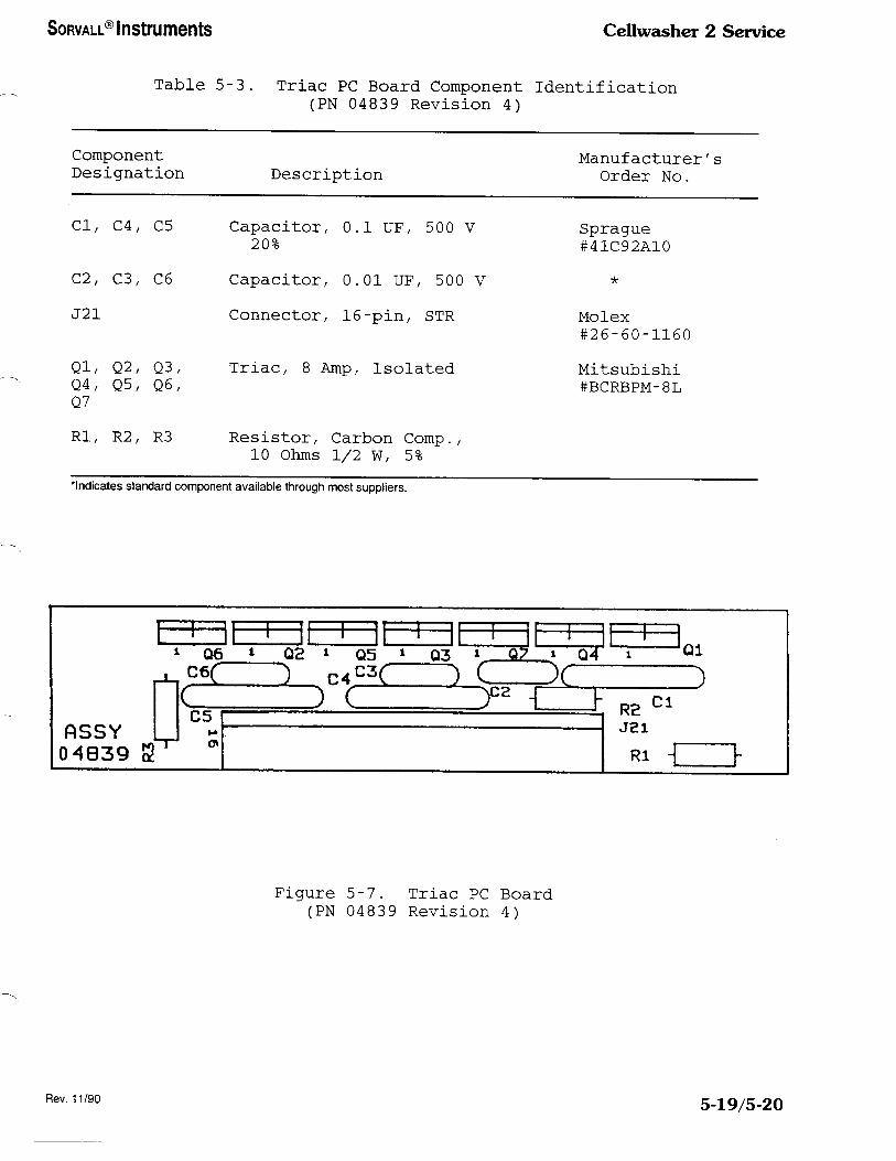
SORVALL® Instruments Ccllwasher 2 Service
Table 5-3. Triac PC Board Component Identification
(PN 04839 Revision 4)
Component
Designation Description
Manufacturer's
Order No.
Cl, C4, C5
C2/ C3/ C6
J21
Capacitor, 0.1 UF/ 500 V
20%
Capacitor, 0.01 UF/ 500 V
Connector, 16-pin/ STR
Ql, Q2, Q3/ Triac/ 8 Amp, Isolated
Q4, Q5, Q6,
Q7
Rl, R2, R3 Resistor, Carbon Comp.,
10 Ohms 1/2 W, 5%
Sprague
#41C92A10
Molex
#26-60-1160
Mitsubishi
#BCRBPM-8L
'Indicates standard component available through most suppliers.
flSSY
04839 S
i ii i
i 06 i Q2
C6( ) r"——L
>-« 0>
)
1 11 1 11
' ,lh
1 Q5 * Q3 l 07
f^^C ) C
) ( ^ -T
1 Q4
x
h
—1—
i
)
R2 c1
J21
Rl -
Ql
Figure 5-7. Triac PC Board
(PN 04839 Revision 4)
Rev. 11/90 5-19/5-20

Son~all® Instruments ~~~~~~~~~~ 2 Service
~~~~~ ~~~ ~~~~~\~~ss'~.~~~~~~~9
~~~ ~~
~~ \ A ~~20 ~ ~~~~ ~~~ ~~~~~~
————— ~ ~~~~ ~~ ~ ~ ~ ~ ~ \ ~~ ~ ~~ ~~
3600 ~~~ ~~——~~
~~00 ~~~~ 5~~——
600 ~~~~~ 6~——\
~~~~~ ~ ~——~
~~~~~~ 3
~——~~0~£~~
~~ ~——1
~~ LATCH~~ ~ ~———————— - ~~1
~~
~ +~ \I~~~——
r~~———~
~~———~
~~——————————————————
~~
~
~~~~ ~~0
~~~~
~~~~~~ ~
~~? ~~~ ~
~4~ ~~~
~~~
~~~~~~~~ ~
~
~~5 ~~ ~
~
~7 ~~~ ~
~~1 ~~~ 333~
~~ HOC ~S3~
Z3 HOC 3021
~~4 HOC ~~~l~
~~ ~~~~ ~~~~~
~~~
~oc
3~Si
~7 m~ 303~
~~~ 9 ~——r ~——————~ ———————————~ ~~~~~ ~~~ ~~ ~ ~ ~~~ ~ ~
~?S ~ ~~~~~ ~~ ~~~~~ ~~~~~ ,~~0 ~59 ~Of ~~ ~~~~~—~~ ~ ~~———~~———1————~~~/S ~~~~~
~
~~~~ \~~~s ~~~————————~~~~~——~~~~
~ ~ ~~~~~ ~ ~ ~ ~~~~~ ~3~~ •~
~~~—~~~~—~~———~~——~————~—~~~ 3600~~~ ~~~~
~
~~~~~ ~~~~?/~~ ~ ~~~~~ ~ ~~O ~ ~~~ ~~~ ~~ ~~~
~—~~~~~~~~———~~——~————1—~~~ ~~~~~~~~4
~~~~ ~~ ~~~~~~ ~~~—————————1 ~ \ ~~2~ ~~~
~~~~ ~~o 39 •~~ ~~
°——~~—~~~~————~~———~~~~~~~~4~~~ 600~~~~
~~~~4
~~~ ~~~~ ~?~~~ ~ ~~~~ ~ ~~~~
~ ~~~ 39 •~~~ ~~ ~—~~—i—~~———~~———i————~~~~~~~ ~~~~~
~~~
4
~~~~ ~ ~ ~ \ ~~~ ~~ 5~
6 ~SO 39 •~~ ~
~~~ ~~
~—\ ——~ ~~
~?/4 ~?27 ~~~ ~/~
~ ~~~~ ~ ~~~ ~~~~~ ~ ~~
~~~~
~~
~~~~~~~~~~~ \~,~~
~~~~~~——~ ~~
~~~~~\ ~~ ~~ ~
~~ ~~ ~~ ~\ ~ ~ ~ ~~ ~~ ~ ~ ~~
~ ~~ ~ | ~ ~~ ~~ ~
~ ~~~~ ~~~ I ~~ ~~~ ~~ ~~~| ~~~~~ ~
~~6 7~~6~~E~
~~———~ ~~~————~~ ~ ~~ ~ ~ ~~ ~ ~~~~~
~7
7~~SS~~~~~~~————~~~~ ~~~
~ ~~ ~\ \~ ~~ ~~ ~~ ~~ Y ~~ ~~~| ~~~~
+5~ ~ ~~~
~———\
~~F2 ~~~~~~
1
~~~ 1~
~~~ ~
~01 ~7~ 500V
~ ~e~~~
~ ~~
1 r ~
~ ~
~~~
~1,500V ~~~~~~
~~ ~
~~~ ~ ~~~0~~ ~~~~~~
~ ~h
—~~ ~~~~~
~~,~~~~~ ~~~~~~ ~~ A
~~~~
1~~ ~~~~~1 ~~~
~~~~
I ~ ~~ ~
~1,~~~~ 10,~~~ ~ A ~~~~~
7~S~~~~
—~~ ~~~
~~~ ——~~~—~
~
<~~~~~~
~
~~
~~~
2
3
~~
5
4
F~~
~~~
~~~2~
~~ ~~~~~~~~D~~~
Y
~~?~
~~~~~~——~——————— ~ A~~
~~~~ ~~~ ~~~~~~~~~
~~~
5~ ~~~~~~~~~~~~~~ (7~51-~)
5~~~ (~BI-~)
~J
~~~~9 ~2~5 ~7
~1~~~
~~~~9 ~~~~
~~-5
~~~~~~~~~~~~~ ~~~~~~~~~~~~~ ~~~~~~~~~~~ ~~~ ~~~~ ~~~~5~s~~~~~ ~~~~~ ~~~ ~~~-/S ~ ~~~~~~~±~~~~
(~) ~~~~ ~~~~~~.~~~~~5 ~~~~~~ ~~~~~ ~/~~~~~~~~~~~S
~4
~~~ ~~~~~
~~~ ~~~~r~r6~-~~~~
6 ~~~~~~ -
~~f4 ~~~~ ~
->/~ ~~~ -
Figure 5-8.
Schematic, ~~~~~~~~~~~~~~~ PC Board
~~~ 04537, Revision 4)
5-21/5-22
Rev. 11/90
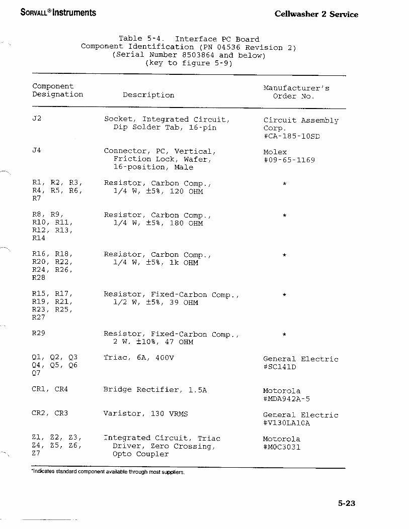
SORVALL® Instruments Cellwasher 2 Service
Table 5-4. Interface PC Board
Component Identification (PN 04536 Revision 2)
(Serial Number 8503864 and below)
(key to figure 5-9)
Component
Designation Description
Manufacturer/s
Order No.
J2 Socket, Integrated Circuit/
Dip Solder Tab, 16-pin
Circuit Assembly
Corp.
#CA-185-10SD
J4
Rl, R2, R3,
R4, R5, R6,
R7
R8, R9,
RIO, Rll,
R12, R13,
R14
R16, R18,
R20, R22,
R24, R26,
R28
R15, R17,
R19, R21,
R23, R25,
R27
R29
Ql, Q2, Q3
Q4, Q5, Q6
Q7
CR1, CR4
Connector, PC, Vertical,
Friction Lock, Wafer,
16-position, Male
Resistor, Carbon Comp.,
1/4 W, ±5%, 120 OHM
Resistor, Carbon Comp./
1/4 W, ±5%, 180 OHM
Resistor, Carbon Comp./
1/4 W, ±5%, 1k OHM
Resistor, Fixed-Carbon Comp.,
1/2 W, ±5%, 39 OHM
Resistor, Fixed-Carbon Comp.,
2 W, ±10%, 47 OHM
Triac, 6A, 400V
Bridge Rectifier, 1.5A
Molex
#09-65-1169
General Electric
#SC141D
Motorola
#MDA942A-5
CR2, CR3 Varistor, 130 VRMS General Electric
#V130LA10A
Zl, Z2, Z3, Integrated Circuit, Triac
Z4, Z5, Z6, Driver, Zero Crossing,
Z7 Opto Coupler
Motorola
#MOC3031
•Indicates standard component available through most suppliers.
5-23

Cellwasher 2 Service SORVALL® Instruments
Table 5-4. Interface PC Board
Component Identification (PN 04536 Revision 2)
(Serial Number 8503864 and below)
(key to figure 5-9) continued
Component
Designation Description
Manufacturer's
Order No.
Cl, C2, C3
C4, C5/ C6
C7
Capacitor, Ceramic Disc/
.01 MFD, 500 WVDC
Sprague
#19C241A2
C8 Capacitor, Electrolytic,
Aluminum Radial, 22 MFD,
25 WVDC
Illinois
Capacitor
#226RLR025M
C9
TP1, TP2
Capacitor, Electrolytic,
Aluminum Radial, 22 MFD,
250 WVDC
Terminal, Swage, 2 Turrett,
Brass, Silver-Plated
Illinois
Capacitor
#226RMR250M
H.H. Smith
#2018C
Figure 5-9. Interface PC Board
(PN 04536 Revision 2)
(Serial Number 8503864 and below)
5-24

~~~~~~~~ Instruments
~5~~
~~5~~
~~~~~~~~~~ 2 Service
~~~~~ ~~ ~—
~~~~0 ~~~~ ~ ~——
~~~~ ~~~~ 5 ~——
~~~~~~ 2 ~
~~~~~ 3 ~—
~~~~ ~~~ 5—
~~ ~~~~~~~ ~~——————————————————————————————————————————————
~~~~~
~~> +~~ ~/2~——1—————————————
~~~————————————————1
~~~~—————~
~
1
1
~ ~~~~
~ ~
~~~o ~
1~~~
~~~~
~~ I~O ~
\~
~
~s~
~4 ~~~~~O ~~
\~~2
~~~~
~~ ~ ~~~ ~
~~~~~
2
~~~~~~
J
~~~ ~~~~
~ +~
J
~~~ ~~1~
2
~1
HOC~~30~1
~~
~~~~3031
~3 HOC
3031
~?~~~HOC
~~~~
~5
~~~~~303~~
~~
~~~~~3~~~
~7
~~~ 30~1
~~~~~4 ~~1~1
~9 ~~O
~
~~~~~ ~~~
010 ~~~
~~~~
4 ~~~~
~~~~~So
Q~~4 SC/~~
Rl2 ~ ~~~
~~~~~~~ ~
~~~~ ~~~4
R13 ~~~
~~~ ~~~~~
R14~ ~ ~~~~ ~
~~1
O~~4 SC~41
~~~~ ~~ R~b ~~~ ~~
~~~ ~7 ~ ~~ ~
~~~~ .0~ ~—————1————~~~——————~~——~—————
~~~~ ~ ~~~~~~~~~ ~~
———————*————~~~~————————
~15~
~e~9 39 ~~~
~~~ .01
~
~~~ ~~~~
~~~~~~ ~
~~~ ~ 3~ - ~ •°~
~~
~ ~~
—————*———~~~——————
~i5~~ ~~3
f ~9 ~~~~~~ ~~~
~~
~~ ~~~
~~~~5~~1 ~~~~~T 39 ~~~
~~~~ ~~~~
~ ~~~ ~~~~~~~~ ~~
~~~ ~
1 3~ C7 ~~~ .01
~ ~~
-
~~~~
~—~~———~———— ~~ ~~~ ~~~ ~' ~
~47~~~~~~ ~~~~~~~~ ~9~ 2~~
~~~
~~ ~—~~~~~~—————
~~
~~ ~~~~~~~~ ~~~~~~~~
~~~~~ ~ ~~~
~~~
~ TP2
1
+lc~~~22
-~
~~~~~1
+1 ~~8 T~ ~~,25V
——~~~ ~~~~~~
—>~2 ~~~~
—~7 D~~~A~~7~ ~~
~——?~9 ~~~~ (T~~
—~ & D~CA~T —
1—~'3 ~~~~~ —
——~~ ~~~~
~~/6 I~~~ V(~B 1-2~~
—~~ ~5~~ ~~~~~~~~~~
~~.~~~~ss ~~~~~~~~~~ ~~~~~~~~~~~ ~~ ~~ ~~~~~~~~~ ~~~£ ~ ~~~~~ ~~~~~~~~~
~~ ~~~ ~~~~~~~~~~~~ ~~~ ~~~~ ~~~~~~~~~~~~
~~~~~~
~~4 ~~~~ ~~~~~~~
Figure 5-10.
Schematic, Interface PC Board
~~~ 04537 Revision 1)
(Serial Number 8503864 and below)
5-25/5-26

SORVALL® Instruments Cellwasher 2 Service
g. Automatic Wash Cycle
When power is applied, the software lights the AUTO, LID and STOP
indicators and displays zeroes on the displays. The drive motor is
placed in the brake mode (a power outage safety precaution) for five
seconds, and all the panel switches except lid are locked out for this
time period. The automatic wash sequence is described in table 5-5 and
illustrated in figure 5-11. Pressing a particular switch in the cycle
column results in particular values showing up in the digital display
as follows:
Cycle Cycle Display Time Display
080
160
240
320
h. Stepping
Each depression of the step switch results in the software avoiding
a particular sequence of the auto cycle as shown below:
Number of Step Automatic Wash Time
Depressions Segments (Seconds)
321 ^Fill 09
I 9 sec._______^^
^ Spin 55
9+55 sec._______^^
^Decant 10
9+55+10 sec._______^
Agitate 06
Since the full step takes 9 seconds, when this step is skipped the
software deducts 9 seconds from the total time displayed. Pressing the
step switch twice results in 9 plus 55 seconds (total of 64) being
deducted, since the spin portion of the cycle takes 55 seconds. An
additional ten seconds are deducted for the decant portion of the cycle
when the step switch is pressed a third time. The software ignores any
further depressions after the third, since the user might as well begin
a new wash cycle by selecting a new cycle number in the cycle column,
pressing STOP in the command column or selecting AUTO in the mode
column.
i. Checking
The checking feature may only be used during the automatic wash cycle.
Once CHECK is pressed, the software stops at the next convenient point:
after fill, after high speed spin, or after the decant segment. Timing
stops and resumes when the run is started again.
5-27
Cellwasher 2 Service SORVALL® Instruments
Lack of saline flow automatically results in a check stop after the
fill segment, an intermittent beeping signal and illumination of the
word saline on the panel. At this point the software allows the user
several options as follows:
1. Do nothing about the lack of saline and continue the run; the
audio warning stops but SALINE remains lit.
2. Prime the system before continuing the run; both the audio
warning and the saline light are turned off.
3 . Disable the audio warning while deciding which option to pursue.
This is done by pressing PRIME* with the lid closed (priming
will not take place unless the lid is open).
j. Alarm
The alarm feature allows the user to request an audible signal when
the instrument times out from an automatic wash cycle. The request may
be cancelled at any time by pressing the ALARM OFF switch. Once the
alarm sounds (a continuous beeping) it can be stopped by pressing ALARM
OFF or STOP.
k. High or Low Spin
Selection of the high or low switch constitutes a manual run. The user
inputs desired run time by using the white portion of the keyboard.
The time is displayed instantaneously, with the latest number selected
appearing on the right of the display after moving previous digits to
the left (the same as a calculator display) . To select a run exceeding
999 seconds, the user presses HOLD. This allows for continuous run which
must be stopped by the operator at the desired time. The time display
will read 0 when HOLD is selected.
NOTE
A five second agitation segment always proceeds a run in
either the high or low mode of operation.
1. Agitate
A five second agitation segment comes at the end of every automatic
wash cycle. Each depression of the agitate switch yields an additional
five seconds of agitation.
•With the exception of STOP, CHECK commands are acknowledged only when the instrument is at rest as indicated by illumination of the
lid light.
5-28

SORVALL® Instruments Cellwasher 2 Service
m. Prime
The system will prime for six seconds each time PRIME is pressed if
the following conditions are met: the instrument is at rest/ the system
is in the AUTO mode/ cycle 2/ and the lid is open. In a saline alarm
situation/ the only condition necessary before selecting PRIME is an
open lid.
n. Stopping
Stop is treated as an emergency situation. The software stops all
operation immediately and prepares the system for a complete restart.
Originally programmed run time is retrieved from memory and displayed.
o. Starting
The software acknowledges the start command under only four situations
as follows:
1. Starting in AUTO mode with the instrument at rest.
2. Starting in AUTO mode with the instrument at CHECK.
3. Starting in manual mode (high or low) with the instrument at
rest.
4. Starting the instrument after stopping as the result of a no
latch situation (latch must now be in place.
In all four of these situations the instrument will not start unless
the following prerequisites are met: the lid is latched/ HOLD or a time
other than 0 has been selected/ the instrument is at rest (lid light
illuminated/ and neither priming nor agitation is in progress.
5-29

Cellwasher 2 Service SORVALL® Instruments
Table 5-5. Automatic Wash Sequence
(key to figure 5-11)
Actions Time (Seconds)
Start 1
1200* rpm (low) ON 1
Pump ON 6
1200* rpm and pump OFF 1
3600** rpm ON 47
3600** rpm OFF 1
Brake ON 5
Brake OFF 2
Decant coil ON 1
600 rpm ON 4
600 rpm OFF 1
Brake ON 2
Brake OFF 1
Decant coil OFF 1
Agitate 5
Delay 1
TOTAL TIME/CYCLE ......... 80
4000 i
3500-
3000-
2500-
SPEED (RPM)
2000.
1500-
1000-
500-
(
•
3 5 10 15 20 25 30 35 40 45 50 55 60 65 70 75 80
—
60Hz
50Hz
FILL r----r '..-.'t
1
i
\ DECANT AGITATE
r\
1 I \ AAAA
HIGH SPEED SPIN
...———.\
\ BRAKING
-<- 50Hz 1
— enu7 1
START TIME (SECONDS)
STOP
Figure 5-11. Cellwasher 2 Automatic Wash Sequence
*1500 rpm for 50 Hz
"3000 rpm for 50 Hz
5-30

SORVALL® Instruments Cellwasher 2 Service
5-2. Touch Switch Panel
This PC board consists of seven LED indicators and twenty-five normally
open switches. Twenty-four of these switches are arranged in a 6 by
4 matrix. A +5 VDC supply is required for the indicators. Refer to figure
5-13, Touch Switch Panel Schematic.
a. Indicators:
By applying +5 VDC at pin 20 of P5/ any of the indicators (AUTO, HIGH/
LOW, CHECK, START, STOP or LID) could be lit by providing a current
path via a 390 ohm resistor to ground (see figure 5-12).
Figure 5-12. Indicator Current Path
b. Switches:
Grounding any of the columns (MODE, CYCLE, TIME I/ TIME 2, TIME or
COMMAND) simulates the scanning of that switch column. Pressing any
switch from that column results in a low voltage level (ground)
appearing on the corresponding data line. A, B, C or D (see table 5-
6). Pull-ups to +5 VDC are required on all four data lines. Pressing
the lid switch only transfers the logic level from lid switch 1 to lid
switch 2.
5-3. Interface PC Board
This board interfaces the low voltage level of the microcomputer with
the high voltage components in the instrument. The board requires +5
VDC and 115 VAC to operate. Figure 5-14 shows the test set-up for the
following circuit functions on the interface PC board: pump, 3600* rpm,
1200** rpm, 600 rpm, and brake. The test set-up for the remaining two
circuit functions, decant and open, is shown in figure 5-15. The
expected response of each of the seven segments of the interface PC
board are described beginning on page 5-35.
*3000 rpm for 50 Hz
*1500 rpm for 50 Hz
5-31/5-32

~~~~~~~~ Instruments ~~~~~~~~~~ 2 Service
~~ ~0
~~~~ 9
~~~ ~~ ~
~ ~~ ~
CH~CK ~3
~~~OD~~~ 5 ~~
5C~ ~~~~~
~~~27~ ~~ ~~
LI~ 51 ~9
~~LID ~~~ ~~3 ~
~~~ ~~~~/~~~~ ~
~~SC4~~7~~~2)
~~~~~~~~~~~~~~~ 6
~~~~~~~~~~~~ ~
~~~~~~ &
~~~
~ ~5~
~ ~
1
~ ~
1
1
1 ~~~1
~ ~
~ 1
1
~ S2
~~~ I
~ 1
~
~~~~
~
\~
~~
~
~~~~————————————
~~ ~
~~
~ ~
~
~
~~~~~
~~~
~ ~~~1
\ ~~~
\
~
~OD~
~;
———~~~~~
~~~~~ ~
~~~~l ~—~ ~
~~~~~———
~~
~~
~~
~—0 0 1
~~~ 1
~~ ~
• ~
| CHECK
~~~~~~
~
~
5~
1
~
56 | ~
~ .
~~57
~~
1
1
58 1 ~
~~YC~E
1
~~~
2
~~~ ~
3
~~0 O~
4
~
~~ ~~~
~~
~
LID
[~0 ~~~~S~
~————————————————————————————~~——————~———
~~~~
\
\
1
1
~
~
~—0 0 5Y~ 5/~
4
~~~ O 5~~ 5/5 ~
7
~~0 0 5~2 ~~/6 ~
~~~~~
~L~RM
~~~~~~~
0 5~3 3/7 ~
————~~——————————
~
[—0 0 5/~
5
~~0 0 5/9 ~
0
~~0 0 S20 ~
~
~~~ 0 ~21 ~
~~~1——————————
1 ~~
~ 1
~~ ~
-
~ ~
~~~ 0 1
5~~~————I—————————
9
~~~~0 0
1 524
C~R~ 1
~~~~~~~ ~
~~~ 9 ~
~~~~~- -1~~
CO~MAND
~~ ~6~~~~~
1
1
1
~
~~ ~
~7~~~?~ I
~~~~ ~
5Z2
~~~~~~~~~
® |
STO~ I
~ 1
PRIM£
~~0 0 |
~~~~7E
~~~
P~~~~~~~
~ ~
l~
~
1
1
1
———————————~~1
1
~~
~
14~ A
~ ~~ B
~~~~
~ 17 ~
Figure 5-13.
Schematic, Touch Switch Panel
5-33/5-34

SORVALL® Instruments Cellwasher 2 Service
a. Pump (refer to figure 5-14)
Connect load and meter (AC) across pin 9 and pin 14 of J4 . Apply
power to the board. Closing Sl at pin 9 of J2 results in a 115 VAC
± 5% reading across the load. Opening Sl results in a .1 ±.5 VAC
reading across the load.
b. 3600 rpm (3000 rpm for 50 Hz/ refer to figure 5-14)
Connect load and meter (AC) across pin 8 and pin 9 of J4. Apply
power to the board. Closing Sl at pin 1'or J2 results in a 115 VAC
± 5% reading across the load. Opening Sl results in .1 ±.5 VAC
reading across the load.
c. 1200 rpm (1500 rpm for 50 Hz/ refer to figure 5-14)
Connect load and meter (AC) across pin 9 and pin 10 of J4. Apply
power to the board. Closing Sl at pin 5 of J2 results in a 115 VAC
± 5% reading across the load. Opening Sl results in .1 ±.5 VAC
reading across the load.
d. 600 rpm (refer to figure 5-14)
Connect load and meter (AC) across pin 9 and pin 12 of J4. Apply
power to the board. Closing Sl at pin 6 of J2 results in a 115 VAC
± 5% reading across the load. Opening Sl results in a .1 ±.5 VAC
reading across the load.
POWER SUPPLY
Q Z 0
<1
u 0 > in +
•>/<1
1-
LU z
1)/ <•
u <
in ^
•>/<' !>/
INTERFACE PC BOARD
J4
< <•
-^HI———L<9<-
DUMMY LOAD
200 n, 200W
AC VOLTMETER
Figure 5-14. Interface PC Board, Test Set-up #1
5-35

Cellwasher 2 Service SORVALL® Instruments
e. Brake (refer to figure 5-14)
Connect load and meter (AC) across pin 9 and pin 11 of J4. Apply
power to the board. Closing Sl at pin 2 of J2 results in a 115 VAC
± 5% reading across the load. Opening Sl results in a .1 ±.5 VAC
reading across the load.
f. Decant (refer to figure 5-15)
Connect load and meter (DC) across pin 6 and pin 7 of J4. Apply
power to the board. Closing Sl at pin 3 of J2 results in a 115 VDC
± 5% reading across the load. Opening Sl results in a .1 ±.5 VDC
reading across the load.
g. Open (refer to figure 5-15)
Connect load and meter (DC) across pin 13 and pin 14 of J4. Apply
power to the board. Closing Sl at pin 16 of J2 results in a 105 VDC
± 5% reading across the load.
Flow, Sl latched and S2 latched are low level signals from the
instrument's flow detector and latching mechanism, respectively.
The destination of these signals is the microcomputer board.
POWER SUPPLY
0
0
c
u Q
in +
•>/<1
h. 3 UJ z
!>/ <f
u
> in
!>/<! !>/
INTERFACE PC BOARD
J4
-^ <r
< <-
DUMMY LOAD
200 ft, 200W
DC VOLTMETER
Figure 5-15. Interface PC Board, Test Set-up #2
5-36

SORVALL® Instruments Ccllwasher 2 Service
5-4. Microcomputer Board
This Board contains a single chip microcomputer (Z4) with resident 2048
bytes of software and a couple of interface circuitries. The
microcomputer chip has four 8 bit input/output ports: 0, I/ 4, 5. The
microcomputer board responds to certain inputs by controlling a set
of outputs.
a. Hardware
Taken as a black box, the input/output configuration of the
microcomputer PC board is as shown in figure 5-16. Input of data from
the touch switch panel is multiplexed. Output II scans all the columns
of switches. A, B, C/ and D inputs could have come from any of the six
columns. The microcomputer scans the touch switch panel at 10
millisecond intervals (see figure 5-17) by placing a low at each of
the scan lines: MODE, CYCLE/ TIME 1, TIME 2, TIME 3 and COMMAND. Pressing
a switch in a column that is being scanned results in the transfer of
a low to the corresponding data line.
Table 5-6 is a mapping representation of the scanning process. For AUTO
to be registered in the microcomputer, the mode column must currently
be under scan (i.e./ the mode line low) and the auto switch must be
pressed. Data on the A, B, C and D data line should be 0 1 1 1. All
the scan lines can be checked in conjunction with the A, B/ C and D
data lines using the touch switch panel (or a simulation) and the
information in Table 5-6. A new input/output format can be constructed
for the microcomputer as shown in figure 5-18.
Input I signals are logic levels from the instrument into the
microcomputer/ while Input II signals are from the user via the touch
switch panel (refer to figure 5-18).
Output I signals are from the microcomputer PC board to the touch switch
panel status indicators. Output II signals are output to control the
instrument components via the interface PC board. In Output III,
"enable" is used to enable or disable the A, B, C, D data tristate buffer
(Z8) . "Beep" activates the beeper. Output IV carries data to the seven
segment LED displays, while Output V selects which of these displays
gets that data.
The refresh rate is once every ten milliseconds (see figure 5-18) for
each of the four displays.
1. Input I:
The first input from the instrument system is the saline flow
signal. During the filling period of the automatic wash, a low
on the flow line is taken by the microcomputer as a no-saline
situation. This signal is the output of the saline detector
switch via the interface board.
5-37

Cellwasher 2 Service SORVALL® Instruments
INPUT/OUTPUT
INPUTS OUTPUTS
FLOW v
Sl LATCHED v
S2 LATCHED \ ————————————7
^—————^
B Y
r
)
-B—I
0 rpm for 50 Hz
0 rpm for 50 Hz
MICROCOMPUTER
BOARD
4-1 g — a L-
( SEGMENT
( DIGIT SE
START .
STOP Y
AUTO .
^———>
^———>
CHECK .
LID .
ALARM ^
SALINE .
MODE .
CYCLE .
TIME 1 Y
TIME 2 .
TIME 3 .
COMMAND .
DECANT Y
BRAKE .
600 RPM .
1200 RPM* .
3600 RPM** .
PUMP .
OPEN .
ENABLE .
BEEP s
II
III
IV
Figure 5-16. Microcomputer Board Input/Output
Configuration
5-38

SORVALL® Instruments Cellwasher 2 Service
-10
bx2)®®®®®®®®® te © ® @ © @ ®
® ® 0 ® ® © ® (D ,® (3) (4) ®
123456 7 0 9 10 11 12 13 14 15 16 17
TIME IN MILLISECONDS
KEY
NUMBER / ACTIVITY PERFORMED
1
2
3
4
5
HOUSEKEEPING
MONITOR
DISPLAY
SCAN
CONTROL
RTN
RTN
RTN
RTN
Figure 5-17. Microcomputer Scan Routine
5-39

Cellwasher 2 Service SORVALL® Instruments
Table 5-5. Microcomputer Scan Map
SWITCH
PRESSED COLUMN SCANNED DATA
MODE CYCLE TIME 1 TIME 2 TIME 3 COMM A B C D
5-40

SORVALL® Instruments Cellwasher 2 Service
INPUTS
INPUT/OUTPUT
FLOW
Sl LATCHED
S2 LATCHED
AUTO
HI
LO
CHECK
CYCLE 1
CYCLE 2
CYCLE 3
CYCLE 4
1
2
3
4
5
6
7
8
9
HOLD/ALARM ON
0/STEP
CLEAR/ALARM OFF
START
STOP
PRIME
AGITATE
MICROCOMPUTER
BOARD
START INDICATOR
STOP INDICATOR
AUTO INDICATOR
HI INDICATOR
LO INDICATOR
CHECK INDICATOR
LID INDICATOR
ALARM INDICATOR
SALINE INDICATOR
DECANT
BRAKE
600 RPM
1200 RPM (1500 rpm-50 Hz)
3600 RPM (3000 rpm-50 Hz)
PUMP
OPEN
ENABLE
BEEP
SEGMENT a )
SELECTOR 9 )
DIGIT Dl )
SELECTOR D4 )
III
IV
Figure 5-18. Creating New Input/Output Formats
5-41
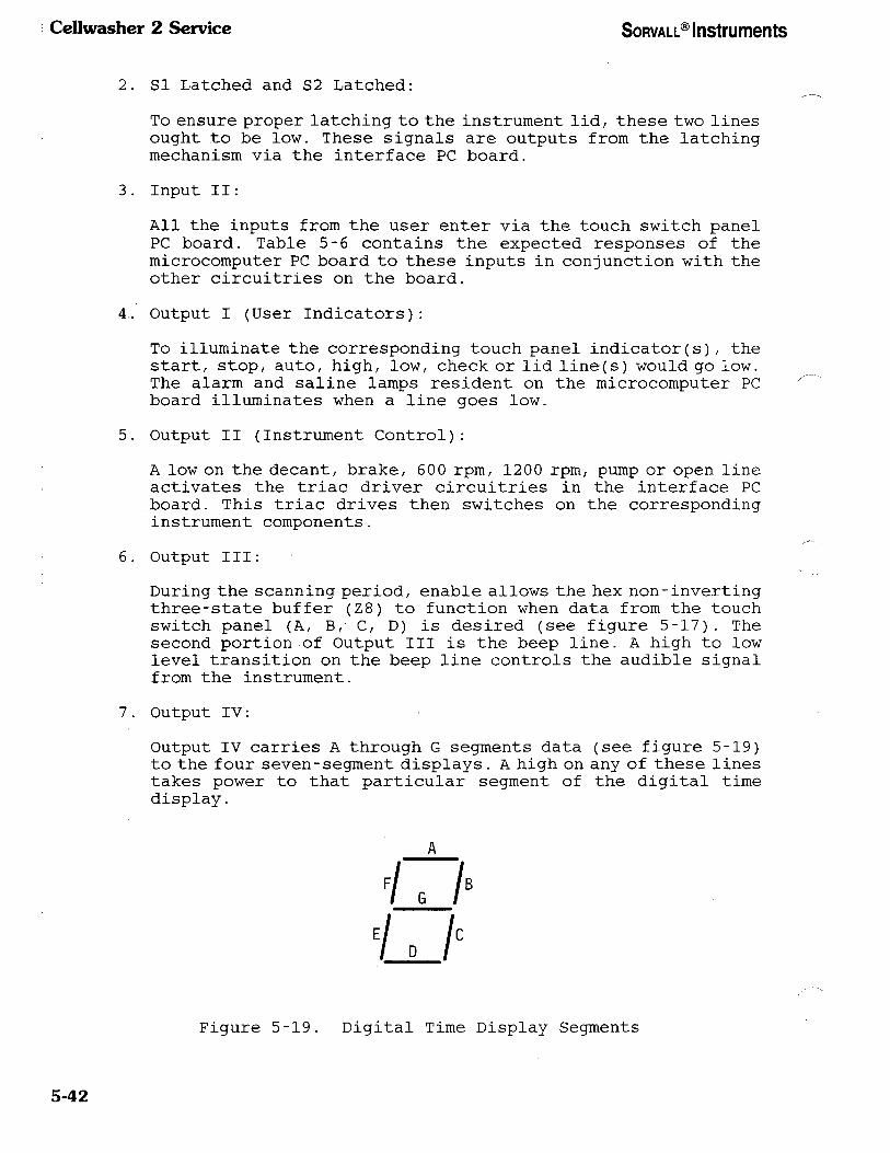
Cellwasher 2 Service SORVALL® Instruments
2. Sl Latched and S2 Latched:
To ensure proper latching to the instrument lid, these two lines
ought to be low. These signals are outputs from the latching
mechanism via the interface PC board.
3. Input II:
All the inputs from the user enter via the touch switch panel
PC board. Table 5-6 contains the expected responses of the
microcomputer PC board to these inputs in conjunction with the
other circuitries on the board.
4. Output I (User Indicators):
To illuminate the corresponding touch panel indicator(s)/ the
start, stop, auto, high, low, check or lid line(s) would go low.
The alarm and saline lamps resident on the microcomputer PC
board illuminates when a line goes low.
5. Output II (Instrument Control):
A low on the decant, brake, 600 rpm, 1200 rpm, pump or open line
activates the triac driver circuitries in the interface PC
board. This triac drives then switches on the corresponding
instrument components.
6. Output III:
During the scanning period, enable allows the hex non-inverting
three-state buffer (Z8) to function when data from the touch
switch panel (A, B, C, D) is desired (see figure 5-17). The
second portion of Output III is the beep line. A high to low
level transition on the beep line controls the audible signal
from the instrument.
7. Output IV:
Output IV carries A through G segments data (see figure 5-19)
to the four seven-segment displays. A high on any of these lines
takes power to that particular segment of the digital time
display.
A
", "
•/_/•
;/./1
Figure 5-19. Digital Time Display Segments
5-42

SORVALL® Instruments Cellwasher 2 Service
Table 5-7. Electronics Control System
INPUT
(SWITCH PRESSED)
OUTPUT
(RESPONSE)
CONDITIONS
REQUIRED
AUTO
HIGH
LOW
CHECK
CYCLE 1
CYCLE 2
CYCLE 3
CYCLE 4
1 'AUTO' INDICATOR
LINE LOW (INDICATOR
LIT)
2 RELOAD PROGRAMMED
# OF WASH AND TIME
1 'HIGH' INDICATOR
LINE LOW (INDICATOR
LIT)
2 RELOAD PROGRAMMED
HIGH SPIN TIME
1 LOW INDICATOR LINE
LOW (INDICATOR LIT)
2 RELOAD PROGRAMMED
LOW SPIN TIME FOR
DISPLAY
CHECK INDICATOR LINE
LOW (INDICATOR LIT)
DISPLAY 1 080
DISPLAY 2 160
DISPLAY 3 240
DISPLAY 4 320
IN STOP NOT
IN CHECK
IN STOP NOT
IN CHECK
IN STOP NOT
IN CHECK
AUTO MODE
IN START
1 AUTO MODE
2 IN STOP
3 NOT IN CHECK
1 AUTO MODE
2 IN STOP
3 NOT IN CHECK
1 AUTO MODE
2 IN STOP
3 NOT IN CHECK
1 AUTO MODE
2 IN STOP
3 NOT IN CHECK
1 NUMBER DISPLAY
(ON THE RIGHT MOST
DIGIT)
2 PREVIOUS DATA PUSHED
TO THE LEFT.
1 HIGH OR LOW
MODE
2 IN STOP
3 NOT IN CHECK
1 NUMBER DISPLAYED (ON
THE RIGHT MOST DIGIT)
2 PREVIOUS DATA PUSHED
TO THE LEFT
1 HIGH OR LOW
MODE
2 IN STOP
3 NOT IN CHECK
5-43

Cellwasher 2 Service SORVALL® Instruments
Table 5-7. Electronics Control System (continued)
INPUT
(SWITCH PRESSED)
OUTPUT
(RESPONSE)
CONDITIONS
REQUIRED
HOLD
1 NUMBER DISPLAYED (ON
THE RIGHT MOST DIGIT)
2 PREVIOUS DATA PUSHED
TO THE LEFT
1 NUMBER DISPLAYED (ON
THE RIGHT MOST DIGIT)
2 PREVIOUS DATA PUSHED
TO THE LEFT
1 NUMBER DISPLAYED (ON
THE RIGHT MOST DIGIT)
2 PREVIOUS DATA PUSHED
TO THE LEFT
1 NUMBER DISPLAYED (ON
THE RIGHT MOST DIGIT)
2 PREVIOUS DATA PUSHED
TO THE LEFT
1 NUMBER DISPLAYED (ON
THE RIGHT MOST DIGIT)
2 PREVIOUS DATA PUSHED
TO THE LEFT
1 NUMBER DISPLAYED (ON
THE RIGHT MOST DIGIT)
2 PREVIOUS DATA PUSHED
TO THE LEFT
1 NUMBER DISPLAYED (ON
THE RIGHT MOST DIGIT)
2 PREVIOUS DATA PUSHED
TO THE LEFT
1 NUMBER DISPLAYED (ON
THE RIGHT MOST DIGIT)
2 PREVIOUS DATA PUSHED
TO THE LEFT
1 0 DISPLAYED ON
THE RIGHT MOST DIGIT
2 ALL OTHER DIGITS OFF
1 HIGH OR LOW
MODE
2 IN STOP
3 NOT IN CHECK
1 HIGH OR LOW
MODE
2 IN STOP
3 NOT IN CHECK
1 HIGH OR LOW
MODE
2 IN STOP
3 NOT IN CHECK
1 HIGH OR LOW
MODE
2 IN STOP
3 NOT IN CHECK
1 HIGH OR LOW
MODE
2 IN STOP
3 NOT IN CHECK
1 HIGH OR LOW
MODE
2 IN STOP
3 NOT IN CHECK
1 HIGH OR LOW
MODE
2 IN STOP
3 NOT IN CHECK
1 HIGH OR LOW
MODE
2 IN STOP
3 NOT IN CHECK
1 HIGH OR LOW
MODE
2 IN STOP
3 NOT IN CHECK
5-44

SORVALL® Instruments Cellwasher 2 Service
Table 5-7. Electronics Control System (continued)
INPUT
(SWITCH PRESSED)
OUTPUT
(RESPONSE)
CONDITIONS
REQUIRED
CLEAR
ALARM ON
STEP
ALARM OFF
START
STOP
PRIME
1 CLEAR DISPLAY DATA
TO ZEROS
1 ALARM LINE LOW
(LAMP ON)
1 SUBTRACTS FROM
DISPLAY
1 ALARM LINE HIGH
(LAMP OFF)
1 START LINE LOW
(INDICATOR ON)
2 START PROGRAMMED RUN
3 LID LINE HIGH
(INDICATOR OFF)
4 CHECK LINE HIGH
(INDICATOR OFF)
1 STOP LINE LOW
(INDICATOR ON)
3 RELOAD ORIGINALLY PRO¬
GRAMMED DISPLAY DATA
2 DISABLE ALL CONTROL
LINES (STOP RUN)
1 PUMP LINE LOW FOR
6 SECONDS
1 HIGH OR LOW
MODE
2 IN STOP
3 NOT IN CHECK
AUTO MODE
AUTO MODE
IN STOP
NOT AGITATING
NOT IN CHECK
NOT PRIMING
AUTO MODE
DOOR LATCHED
PROGRAMMED
TIME NOT ZERO
LID INDICATOR
ON
AUTO MODE
DOOR OPEN
CYCLE 2 SELECTED
IN STOP NOT IN
CHECK OR
IN STOP IN CHECK
AT "NO SALINE"
POINT
NOT AGITATING
LID INDICATOR ON
5-45

Cellwasher 2 Service SORVALL® Instruments
Table 5-7. Electronics Control System (continued)
INPUT
(SWITCH PRESSED)
OUTPUT
(RESPONSE)
CONDITIONS
REQUIRED
AGITATE
*LID
1 PULSE OF 4 HZ ON
600 RPM LINE
2 PULSE OF 4 HZ ON BRAKE
LINE (PHASE SHIFT OF
170 MS BETWEEN 1 & 2)
1 OPEN LINE LOW
1 IN STOP
2 NOT IN CHECK
3 NOT PRIMING
4 LID INDICATOR ON
LID INDICATOR ON
"Lid switch is not an input to the microcomputer. It is in parallel to the lid indicator which is an output from the microcomputer.
8. Output V:
Dl, D2/ D3 and D4 control display digit selection. A low on any
of these lines selects that particular display.
b. Software
Figures 5-20, 5-21, and 5-22 display all the software activities for
starting in the manual (high or low) mode, check mode, or auto mode
which were not previously discussed under the Hardware section.
5-46

SORVALL® Instruments Cellwasher 2 Service
*1500 rpmfor50 Hz
"3000 rpm for 50 Hz
Figure 5-20. Starting in Manual (High or Low) Mode,
Logic Flow Chart
5-47

Cellwasher 2 Service SORVALL® Instruments
C START ^
Turn CHECK indicator off.
Continue as in
Auto (no check)
Figure 5-21. Starting from Check Mode,
Logic Flow Chart
5-48

SO
RV
AL
L®
In
strum
ents
Cellw
asher
2 S
ervice
N
N
3: X
10 in
££
11
8;
Fig
ure
5-22. S
tarting
fro
m
Au
to
Mo
de/
Lo
gic
Flo
w
Ch
art
5-49

Cellwasher 2 Service SORVALL® Instruments
5-5. Electronics Module
The instruments' s electronics control is composed of the microcomputer
PC board and the touch switch panel. The electronics control turns on
or off the various components of the instrument. By simulating the
instrument components and instrument status - latched and saline flow
- the electronics control can be thoroughly tested independently of
the instrument. This test is performed using control signals and status
information on the microcomputer board's connector, J3.
a. Requirements:
1. +5 VDC from an external supply or from the instrument's supply
to test points 1 and 2 of the interface board.
2 . Touch switch panel must be plugged into the microcomputer board.
b. Performance:
By using pull-up resistors at the microcomputer control signals
(decant, brake, 600 rpm, 1200* rpm, 3600* rpm, pump or open at J3),
a low on any of these lines reveals which instrument component should
be turned on. Instrument status can be simulated as desired by grounding
or otherwise altering lines: flow, Sl latched and S2 latched.
c. Example:
By pressing PRIME under the correct conditions (Sl and S2 latched high
(door open), AUTO mode/ cycle 2) the pump signal line at pin9 of J3
should be low for five (5) seconds.
* 1500 rpm for 50 Hz
"3000 rpm for 50 Hz
5-50

SORVALL® Instruments Cellwasher 2 Service
Section 6. APPLICATIONS
This section describes the use of the Cellwasher 2 in blood testing
procedures. It contains a brief overview of Cellwasher 2 applications,
troubleshooting charts (Table 6-1 through 6-3) for common procedural
errors that may occur during blood testing/ and a glossary of blood
banking terms.
6-1. Cellwasher 2 Application
The Cellwasher 2 is used in routine blood work to speed up and simplify
the procedures for determining human blood groups and types. Often/
the results of blood tests made using the Cellwasher 2 determine donor/
patient compatibility for blood transfusions/ and the results of these
tests must be accurate to prevent serious transfusion reactions.
Although the Cellwasher 2 performs accurate washing, decanting and
centrifugation of samples/ it does not eliminate all potential errors.
If testing procedures provided by the reagent manufacturers are not
followed exactly or if test materials are outdated, accurate test
results cannot be guaranteed. Proper blood bank procedures require
adequate controls of all tests performed with this system.
6-2. Compatibility Testing
In compatibility testing/ blood samples taken from a donor and patient
are crossmatched to ensure that the patient will be able to accept the
donor's blood. An accurate compatibility test is mandatory, since a
transfusion reaction caused by incompatible blood may be fatal. The
crossmatch is a test tube procedure which will show the technician what
will happen if a donor's blood is transfused to a particular patient.
A transfusion reaction occurs when the patient's immune system treats
the transfused blood like a bacterial infection; that is, the
antibodies in the patient's blood plasma agglutinate (bind together)
the donor's red blood cells in an effort to eliminate them from the
bloodstream. Massive agglutination results in restricted blood flow,
which may in turn cause permanent organ damage or death. In addition/
destruction of donor cells releases agents into the bloodstream in
intolerable amounts.
To determine donor/patient compatibility/ the antibodies in the
patient's blood are detected using a laboratory procedure that
simulates conditions within the patient's blood stream during
transfusion. Three tests for compatibility are performed using the
Cellwasher 2.
6-1

Cellwasher 2 Service SORVALL® Instruments
1. Test for direct-reacting antibodies:
Direct-reacting antibodies agglutinate red blood cells readily.
For this test, a suspension of red blood cells in saline is combined
with human blood plasma in test tubes and spun in the Cellwasher
2. When centrifuged, the antibodies and red cells are brought close
enough together to allow agglutination to occur. The test tubes
are removed from the Cellwasher 2, and results are read over a light
source. Agglutination indicates the presence of antibodies in the
plasma against antigens on the red cell surface.
2. Test for warm-reacting antibodies:
Warm-reacting antibodies will agglutinate red cells only after
incubation at 37 C. In this test, the red cells are suspended in
albumin, then combined with human plasma. The test tubes are then
spun again and read to determine test results.
3. Test for Coomb's reacting antibodies:
Coomb's reacting antibodies will agglutinate red cells only from
which all unattached protein have been removed. In the Coomb's
test, anti-human serum (one which contains antibodies derived from
animal) is added to red cells that have been washed to remove
unattached human protein. This combination is then centrifuged to
determine test results.
6-3. Cellwasher 2 Washing Cycle
For the Coomb's reaction to occur, the suspension of red blood cells
must first go through the complete washing cycle. The washing cycle
removes unattached protein from the red cell suspension through a
series of dilutions with saline.
During the washing cycle, plasma and red blood cells are separated by
centrifugation. The saline is pumped into the test tubes automatically
and the tubes are centrifuged again. The saline is then decanted
automatically by centrifugation, with the test tubes at a -5 angle.
The washing cycle can be repeated automatically up to four times by
setting the number of washes on the wash cycle selector.
6-2

SORVALL® Instruments Ccllwasher 2 Service
Table 6-1. APPLICATIONS TROUBLESHOOTING
CHART: FALSE NEGATIVE RESULTS
PROBLEM
Modify the cell suspension concentration.
Repeat the test, noting antiglobulin step.
Repeat the test with fresh reagent.
Repeat the test with fresh reagent.
1. Check the incubation time.
2. Check the volume of reagent added.
Increase spin time.
6-3

Cellwashcr 2 Service SORVALL® Instruments
Table 6-2. APPLICATIONS TROUBLESHOOTING
CHART: FALSE POSITIVE RESULTS
PROBLEM
1. Change the saline supply.
2. Clean and decontaminate the tubing and
the distributor.
Change the tubing if necessary.
Repeat the test with fresh reagent cells.
Crossmatch versus fresh reagent.
Test the patient serum for bacterial
contamination.
1. Test versus fresh reagent.
2. Observe patient red blood cells
microscopically..
Decrease spin time.
6-4

SORVALL® Instruments Cellwasher 2 Service
Table 6-3. APPLICATIONS TROUBLESHOOTING
CHART: INCONSISTENT REACTION STRENGTH
PROBLEM
1. Change the saline supply.
2. Clean and decontaminate the tubing and
the distributor.
Change the tubing if necessary.
Repeat the test with fresh reagent cells.
Crossmateh versus fresh reagent.
6-5

Cellwasher 2 Service SORVALL® Instruments
6-4. Glossary of Blood Banking Terms
The following glossary contains common terms used in blood banking
procedures. For more in-depth applications information, refer to the
Technical Manual of the American Association of Blood Banks.
Agglutination:
Agglutin:
Agglutinogen:
Antibody:
Antigen:
Antigenic Determinant:
Antigenicity:
Antiglobulin:
Autoagglutinin:
Autoantibody:
Avidity of an
Antiserum:
Blocking Antibody:
6-6
The clumping of red blood cells by ag-
glutins.
An antibody that causes clumping of red
cells in a saline medium by reacting with a
specific antigenic determinant.
An antigen that stimulates the production of
agglutinins.
A substance that appears in plasma or body
fluids as a result of antigenic stimulation
and reacts specifically with that antigen in
some observable way.
A substance that, when introduced into a
person lacking this substance, stimulates
production of an antibody.
The portion of an antigen that reacts in a
specific, demonstrable way with an anti¬
body.
The ability of an antigen to stimulate
antibody production.
An antibody produced in an animal in
response to the injection of human globulin;
also called anti-human globulin.
An agglutinin that reacts with the red blood
cells of the person in whose serum it is
found; it usually agglutinates the red blood
cells of most other persons also.
An antibody that reacts with the red blood
cells of the person in whose serum it is
found; it usually reacts with the red blood
cells of most other persons also; see
autoagglutinin.
The strength of reaction between an anti
serum and the corresponding red blood cells .
An incomplete antibody that coats the
receptor sites of red blood cells and
prevents subsequent reaction with a saline
agglutinin directed against the antigenic
determinant.

SORVALL® Instruments Cellwasher 2 Service
Blood Group:
Chromosome:
Cold Agglutinin:
Complement:
"Complete" Antibody:
Coombs Test:
Crossmatch:
Enzyme-treated Cells:
Globulin:
Hemolysins:
Hemolytic Disease
of the Newborn:
Hemolytic Transfusion
Reaction:
Hemolyzed:
Immunization:
Incomplete Antibody:
Classification of blood according to anti¬
gens possessed by the red blood cells.
One of a number of rod-shaped dark staining
bodies situated in the nucleus of a cell/
only distinguishable at the time of cell
division. Genes are presumed to exist in
linear arrangement on the chromosomes.
An agglutinin reacting best in a cold
environment (for example, 4 C) with progres¬
sively decreasing activity at higher tem¬
peratures; usually nonreactive at 37 C.
A complex of substances in fresh normal
serum, causing lysis of red blood cells
sensitized by hemolysins.
An antibody that agglutinates red blood
cells in saline solution.
A test of red blood cells by antiglobulin
technic.
An in vitro test of serologic compatibility
between a donor' s blood and that of a
prospective recipient.
Red blood cells treated with a proteolytic
enzyme to be used for antibody identifica¬
tion or demonstration.
A variety of protein found in serum.
Antibodies are globulins.
Antibodies that activate the complement
system, leading to lysis of red blood cells
with the corresponding antigens.
(Erythroblastosis fetalis) A disease caused
by a maternal blood group antibody attacking
fetal red blood cells.
A reaction associated with destruction of
red blood cells in vivo following transfu¬
sion, usually due to serologic incompati¬
bility between donor and recipient.
Disrupted cells.
The process by which an antibody is produced
in response to an antigenic stimulus.
An antibody that adheres to the surface of
red blood cells suspended in saline but
fails to agglutinate them.
6-7

Cellwasher 2 Service SORVALL® Instruments
Iln Vitro:
In Vivo:
Irregular Antibody:
Isoagglutinin:
Isotonic Sodium
Chloride (Saline)
Laked/Lysis:
Panel of Cells:
Reagent Red Blood
Antibody Cells
(Human):
Sensitization of
Red Blood Cells:
Specificity:
Titer:
Titrate:
Warm Antibody:
Wash:
6-8
Pertaining to a process or reaction occur¬
ring outside of a living organism, usually
under laboratory conditions (for example,
in a test tube).
Pertaining to a process or reaction occur¬
ring in a living organism.
An antibody not regularly present in the
plasma, e.g., anti-RH (d) in Rh-negative
person.
An agglutinin directed against an antigenic
determinant found in an individual of the
same species.
0 . 85%-0 . 9% aqueous solution of sodium chlor¬
ide (8.5 gram Nad/liter = 0.85% normal
saline).
The disruption of cells.
A set of reagent red blood cells of known
antigenic content, specially selected and
used for the identification of blood group
antibodies.
Red blood cells used in laboratory testing
ing, e.g., in antibody detection and ident¬
ification of blood group antibodies.
Red blood cells are said to be sensitized
when they have antibody specifically at¬
tached to their receptors but are not
agglutinated or lysed.
The capacity of an antibody to react only
with certain chemical groupings possessed
by the antigen that stimulated its formation
and sometimes possessed by other substances
as well.
The end point of a titration.
To determine the strength of an antigenic
determinant or an antibody by making a
series of dilutions and testing their
strength against a corresponding antibody
or antigenic determinant of known strength.
An antibody reacting at 37 C more readily
than at lower temperatures.
Successive centrifugation of cells in large
volumes of saline to free them from the
liquid in which they were originally sus¬
pended (usually serum or plasma).

SORVALL® Instruments Cellwashcr 2 Service
Section 7. TROUBLESHOOTING
This section contains troubleshooting charts to locate the probable
cause of mechanical and electrical problems that may occur in the
Cellwasher 2. Refer to Section 5 for schematics and wiring diagrams
as needed. If repair or replacement is required, refer to section 8.
WARNING
Because tampering with high voltage electrical circuits
can cause severe electrical shock/ untrained personnel
must not attempt to test or repair any electrical circuits
in this instrument.
If the instrument has been used with radioactive or
biohazardous samples, it may be contaminated. The
instrument and rotor must be certified free of biological
or radioactive contamination: a Decontamination Informa¬
tion Certificate must be filled out by the user.
Appropriate precautions and decontamination procedures
must be followed when servicing the instrument. DO NOT
service or repair any equipment for which the proper
decontamination procedures have not been performed.
Rev. 11/90 7-1
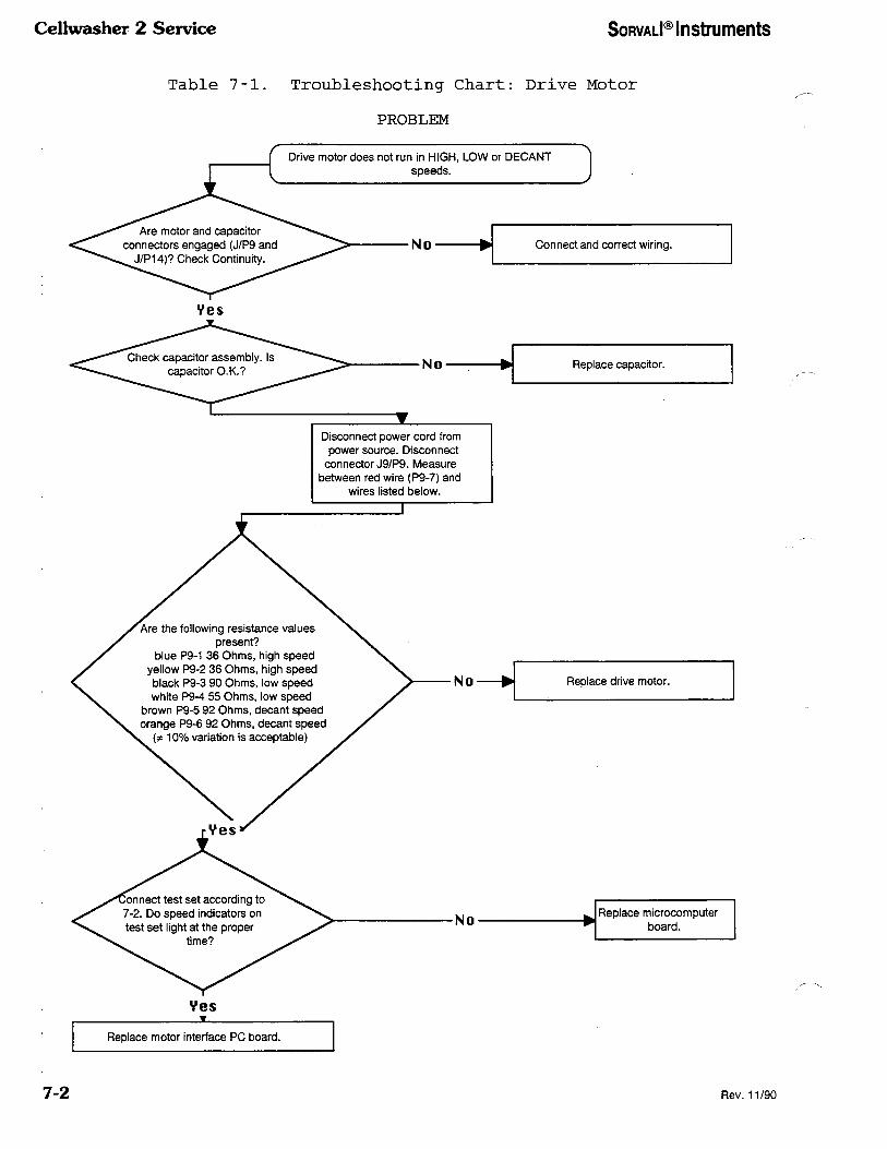
Cellwasher 2 Service SORVALI® Instruments
Table 7-1. Troubleshooting Chart: Drive Motor
PROBLEM
7-2 Rev. 11/90

SORVALL® Instruments Cellwasher 2 Service
Table 7-2. Troubleshooting Chart: Power
PROBLEM
Cellwasher inoperative and displays not illuminated. )
Rev. 11/90 7-3

Cellwasher 2 Service SORVALI® Instruments
Table 7-3. Troubleshooting Chart: Saline Fill
PROBLEM
^ Improper saline fill of tubes.
7-4
V e S w( Replace gasket.
Rev. 11/90
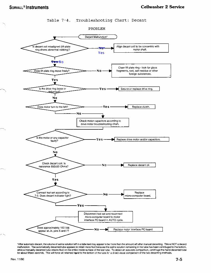
SORVALL® Instruments Cellwasher 2 Service
Table 7-4. Troubleshooting Chart: Decant
PROBLEM
'After automatic decant, the volume of saline solution left in a tube test may appear to be more than the amount left after manual decanting. This is NOT a decant malfunction. The automatically decanted tube appears to retain more fluid because the saline solution remaining in the tube has been centrifuged to the bottom, while a manually decanted tube retains fluid on the entire inside surface of the test tube. To obtain an accurate comparison, centrifuge the hand-decanted tube for about fifteen seconds. This will force all retained liquid to the bottom of the tube for a direct visual comparison of the two decanting methods.
Rev. 11/90 7-5
Emil Heerman
Yes
Emil Heerman
No
Emil Heerman
Emil Heerman

Ccllwasher 2 Service SORVALI® Instruments
Table 7-5. Troubleshooting Chart: Lid Latch
PROBLEM
Check magnet in lid. Replace
latch assembly.
Replace micro computer board.
7-6 Rev. 11/90

SORVALL® Instruments Cellwasher 2 Service
\ DECANT COIL
Figure 7-1. Location of Decant Coil and Drive Ring
Figure 7-2. Location of Lift Plate Ring
Rev. 4/96 7-7/7-8

SORVALL® Instruments Cellwashcr 2 Service
Section 8. REPAIR and REPLACEMENT PROCEDURES
This section contains repair and replacement procedures for the
Cellwasher 2. Should service beyond the scope of this manual be
necessary, contact your DuPont Service Representative. Be sure the
user has performed appropriate decontamination procedures/ as
outlined in paragraph 1-3, before attempting any repair or replacement
procedures on the instrument.
WARNING
Because tampering with high voltage electrical cir¬
cuits can cause severe electrical shock/ untrained personnel
must not attempt to test or repair any electrical circuits
in this instrument. Unplug the Cell-washer 2 before
proceeding.
8-1. Base Plate Removal
a. To remove the base plate:
1. Unplug the instrument power cord.
2. Remove the distributor, rotor and stainless steel rotating
bowl assembly from inside the cellwasher chamber.
3. Turn the instrument on its side.
4. Remove the four (4) mounting screws and rubber feet.
5. Remove the base plate.
b. To replace the base plate, reverse the above procedure.
8-2. Cabinet Removal
a. To remove the cabinet:
1. Switch the power ON and press the LID button to release the
lid.
2. Switch the power OFF and unplug the instrument power cord.
3. Disconnect the tubing from the saline flow detector (the
tubing that connects the detector to the dispenser in the lid) .
4. Remove the wet guard.
5. Remove the four (4) 1/4-20 x 1-3/4 inch long socket head screws
that secure the cabinet to the chassis using a 3/16 inch Alien
wrench.
8-1

Cellwasher 2 Service SORVALL® Instruments
6. Lift the cabinet up approximately four (4) inches to
disconnect the lid latch cable connector (squeeze the two
locking tabs on the connector) located to the left rear corner
of the instrument.
7. Lift the cabinet off of the chassis.
b. To replace the cabinet, reverse the procedure given above and
on the previous page.
8-3. Front Panel Replacement
a. To remove the front panel:
1. Remove the cabinet (paragraph 8-2).
2 . From behind the front panel, remove the four (4) mounting nuts
and washers.
3. Remove the front panel/front wet guard from the chassis.
4. Disconnect the harness connector located at the back of the
front wet guard.
5. Remove the electrical tape at the top edge of the front panel/
front wet guard. Separate the front panel from the front wet
guard, then disconnect connector located inside the front wet
guard.
NOTE
• When reassembling the front panel and front wet
guard, be sure to fold the antistatic electronic
guard (tab), located on the lower right corner of
the front panel, over the edge of the front wet guard
and stud of the front panel.
• To ensure electrical continuity, place a star washer
on the stud which has the antistatic electronic
guard (tab).
b. To replace the front panel, reverse the above procedure.
8-2

SORVALL® Instruments Ccllwashcr 2 Service
8-4. Power Switch Replacement
a . To remove the power switch:
1. Remove the base plate (paragraph 8-1).
2. Remove the two (2) mounting screws from the power switch.
3. Disconnect the connector and remove the switch.
b. To replace the power switch, reverse the above procedure.
8-5. Pump Replacement
a. To remove the pump:
1. Remove the base plate (paragraph 8-1).
2. Remove the four (4) thumb screws from the front of the pump
assembly, and remove the front half of the pump head.
3. Remove the four (4) screws that attach the rear half of the
pump to the frame, and remove the rear half of the pump.
b. To replace the pump, reverse the above procedure.
8-6. Pump Motor Replacement
a. To remove the pump motor:
1. Remove the pump (paragraph 8-5).
2. Remove the rear wet guard.
3. Disconnect the pump motor connector from the harness.
4. Remove the four motor mounting screws.
5. Disconnect the motor ground.
b. To replace the pump motor, reverse the procedure given above and
on the previous page.
8-3
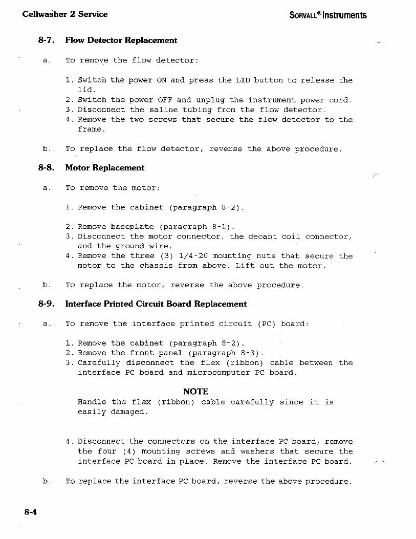
Cellwasher 2 Service SORVALL® Instruments
8-7. Flow Detector Replacement
a. To remove the flow detector:
1. Switch the power ON and press the LID button to release the
lid.
2. Switch the power OFF and unplug the instrument power cord.
3. Disconnect the saline tubing from the flow detector.
4. Remove the two screws that secure the flow detector to the
frame.
b. To replace the flow detector, reverse the above procedure.
8-8. Motor Replacement
a. To remove the motor:
1. Remove the cabinet (paragraph 8-2).
2. Remove baseplate (paragraph 8-1).
3. Disconnect the motor connector, the decant coil connector,
and the ground wire.
4. Remove the three (3) 1/4-20 mounting nuts that secure the
motor to the chassis from above. Lift out the motor.
b. To replace the motor, reverse the above procedure.
8-9. Interface Printed Circuit Board Replacement
a. To remove the interface printed circuit (PC) board:
1. Remove the cabinet (paragraph 8-2).
2. Remove the front panel (paragraph 8-3).
3. Carefully disconnect the flex (ribbon) cable between the
interface PC board and microcomputer PC board.
NOTE
Handle the flex (ribbon) cable carefully since it is
easily damaged.
4. Disconnect the connectors on the interface PC board, remove
the four (4) mounting screws and washers that secure the
interface PC board in place. Remove the interface PC board.
b. To replace the interface PC board, reverse the above procedure.
8-4

SORVALL® Instruments Cellwasher 2 Service
8-10. Microcomputer Printed Circuit Board Replacement
a. To remove the microcomputer printed circuit (PC) board:
1. Remove the cabinet (paragraph 8-2).
2. Remove the front panel (paragraph 8-3).
3. Carefully disconnect the flex (ribbon) cable between the
interface PC board and the microcomputer PC board.
NOTE
Handle the flex (ribbon) cable carefully since it is -
easily damaged.
4. Disconnect the connectors on the microcomputer board/ remove
the four (4) mounting screws/ then remove the microcomputer
PC board.
NOTE
If the microchip is being replaced see figure 5-3 for correct
orientation.
b. To replace the microcomputer PC board/ reverse the above
procedure.
8-11. Fuse Replacement
a. To remove the fuse in the power supply adapter:
1. Unplug the instrument power cord.
2. Remove the power cord from the power supply adapter.
3. Slide the clear plastic guard to the left of the power cord
connection.
4. Pull out the "FUSE PULL" lever. The end of the fuse will pop
out.
5 . Remove the fuse.
b. To replace the fuse, insert the appropriate slow-blow fuse as
indicated on the rating plate at the back of the instrument.
Move the guard to the right and replace the power cord.
8-5/8-6
SORVALL® Instruments Cellwasher 2 Service
Section 9. KIT INSTRUCTIONS
This section includes installation instructions for all available
Cellwasher 2 Cell Washing System service kits.
Rev. n/90 9-1

Cellwasher 2 Service SORVALL® Instruments
9-1. Tubing Replacement Kit, PN 12977
A. Parts Supplied
This kit is supplied with three lengths of tubing: one (1) piece of
pump tubing, measuring 10 inches long (PN 04590), one (1) length of
tubing measuring 78 inches long (PN 04876 is 5/16 inch x 7/16 inch)
and one (1) length of tubing measuring 114 inches long (PN 04875 is
1/4 inch x 3/8 inch). The serial numbers given in the table below
indicate which tubing is to be used with your Cellwasher 2.
NOTE The table specifies the proper tubing lengths that are to be cut from tubing, PN 04875
and PN 04876, respectively. Figure 9-1 on the next page shows the parts location.
Item
1
2
3
4
5
6
7
8
9
10
—
—
Description
Overflow Tubing 15 cm (6 inches) long
Vent Tubing 10 cm (4 inches) long
Pump Tubing 25 cm (10 inches) long
Flow Tubing 30 cm (12 inches) long
Discharge Tubing 22 cm (8.5 inches) long
Supply Tubing 60 cm (24 inches) long
Drain Tubing 121 cm (48 inches) long
Pump Connector
Y-Connector
Adjustable Tubing Clamp
Nylon Cable Tie
Installation Instructions
Part Number
SN 9302849
and above
04876(1)
04876(1)
04590(1)
04875(1)
04876(1)
04875(1)
04876(1)
65762(1)
62842 (2)
68671 (2)
65925 (2)
04640(1)
(Quantity)
SN 9302848
and below
04875(1)
04875(1)
04590(1)
04875(1)
04875(1)
04875(1)
04875(1)
65762(1)
62842 (2)
68671 (2)
65925 (2)
04640(1)
B. Tubing Replacement
NOTE If sterilization of the tubing (and connectors) is required, autoclave for 20 minutes at
121°C, then replace tubing as described on the following pages. The tubing (and
connectors) will be very hot once autoclaved and should not be handled until cooled
completely. Also, the tubing can become deformed if handled immediately after it has
been autoclaved.
1. Set the power switch ON and press the LID button to release the
lid.
AWA R N I N G
Because the Cellwasher 2 has high voltage electrical circuits that can cause
severe electrical shock, this procedure must be done by a technician who is familiar with
electrical circuits. To remove the potential of electrical shock, unplug the power cord
before proceeding.
9-2 Rev. 4/96
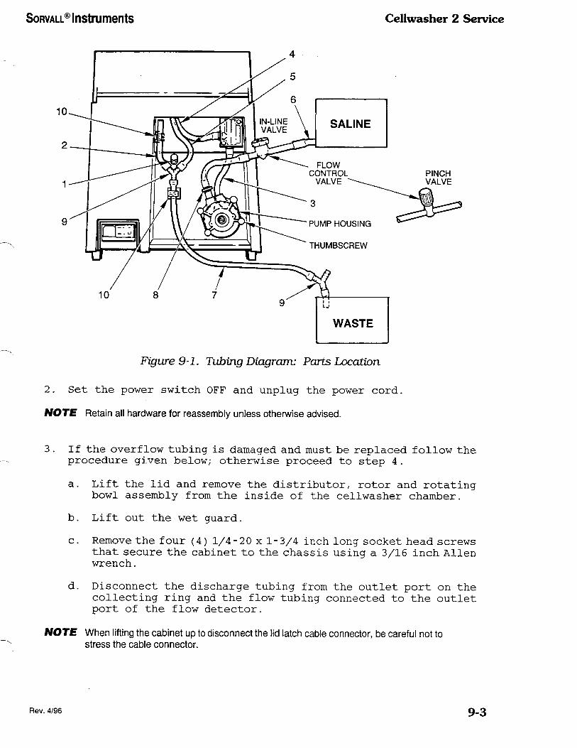
SORVALL® Instruments Cellwashcr 2 Service
Figure 9-1. Tubing Diagram: Parts Location
2. Set the power switch OFF and unplug the power cord.
NOTE Retain all hardware for reassembly unless otherwise advised.
3. If the overflow tubing is damaged and must be replaced follow the
procedure given below; otherwise proceed to step 4.
a. Lift the lid and remove the distributor, rotor and rotating
bowl assembly from the inside of the cellwasher chamber.
b.
c.
Lift out the wet guard.
Remove the four (4) 1/4-20 x 1-3/4 inch long socket head screws
that secure the cabinet to the chassis using a 3/16 inch Alien
wrench.
d. Disconnect the discharge tubing from the outlet port on the
collecting ring and the flow tubing connected to the outlet
port of the flow detector.
NOTE When lifting the cabinet up to disconnect the lid latch cable connector, be careful not to
stress the cable connector.
Rev. 4/96 9-3

Cellwasher 2 Service SORVALL® Instruments
e. Lift the cabinet up about four (4) inches. Then, while holding
the cabinet in one hand, reach in through the front panel
opening, to the left rear corner of the instrument and
disconnect the lid latch cable connector by squeezing the two
locking tabs on the connector.
f. Lift the cabinet off the instrument chassis and place it aside
for reassembly.
g. From the back of the motor drain tray remove the overflow
tubing (the tubing may be secured with a nylon cable tie).
h. Cut a length of tubing 15 cm (6 inches) long to be used as
overflow tubing. Then, install the tubing to the motor drain
tray connector. Secure in place using a nylon cable tie
(PN 65925) supplied.
Motor Protection: The overflow tubing allows saline to flow
onto the counter top alerting the operator of a problem with
incorrect saline levels or tube failure.
i. Bring the overflow tubing through the hole in the back of the
cabinet. The tubing will hang free.
j . Place the cabinet over the chassis and reconnect the lid latch
cable connector.
NOTE Make sure the cable connector is properly and securely connected and that the wires
on the chassis are not "pinched" when the cabinet is put in place.
k. Secure the cabinet to the chassis using the four (4) 1/4-20
x 1-3/4 long socket head screws removed in step 3c above.
1. Replace wet guard.
4. Replace the flow tubing connected to the nozzle in the lid as
follows:
a. Open the lid.
b. Remove the four black screws that secure the collecting ring
assembly to the lid.
c. Remove the collecting ring assembly.
d. Disconnect the flow tubing from the nozzle in the lid and from
the flow detector, if not already done. Discard tubing.
e. Cut a length of tubing 30 cm (12 inches) long to be used as
flow tubing. Attach the flow tubing to the outlet port of the
flow detector.
f. Feed the free end of the flow tubing from the flow detector
through the hole in the back of the cabinet, and connect it
to the nozzle in the top of the lid.
9-4 Rev. 4/96

SORVALL® Instruments Cellwashcr 2 Service
h. Secure the collecting ring assembly in place using the four
black screws.
5. Turn the instrument so that the back of instrument faces you.
6. Remove and discard the supply tubing from the saline supply
reservoir to the flow control valve and from the flow control valve
to the pump connector located on the left side of the peristaltic
pump. Retain the flow control valve for reassembly.
7. Disconnect the pump tubing from the inlet port on the flow
detector. Then, remove the pump tubing from the peristaltic pump
as follows:
a. Remove the four knurled thumbscrews from the peristaltic pump
and remove the front half of the pump housing. Set the pump
housing and hardware aside for reassembly.
b. Remove the pump tubing and connector being careful not to
remove the pump roller assembly. Discard the pump tubing and
the connector.
8. Remove the T-Connector or Y-Connector (with vent tubing/
discharge tubing and drain tubing attached) by pulling up on the
tab corners of the two adjustable tubing clamps.
9. Disconnect the discharge tubing from the outlet port on the
collecting ring, if not already done.
NOTE Before discarding the drain tubing (attached to the bottom leg of a Y-Connector or
T-Connector) remove the connector, if used. Be sure to retain the connector for
installation of new drain tubing.
10. Discard the discharge tubing/ the vent tubing/ the drain tubing
and the T-Connector. Retain the Y-Connector if used.
11. Check the two adjustable tubing clamps for damage and that they
have not become loosened. If the adjustable tubing clamps are
damaged or loose/ replace as follows:
a. Remove and discard damaged or loosened adjustable tubing
clamp.
b. Clean the surface with alcohol or solvent to remove any
residue.
c. Peel the protective sheet from the adhesive back of the
adjustable tubing clamp and approximately position clamp(s)
as shown in figure 9-2.
Rev. 11/93 9-5

Cellwasher 2 Service SORVALL® Instruments
19mm
(0.75 in)
Figure 9-2. Adjustable Tubing Clamp Location
12. Install the pump tubing (PN 04590) as follows:
a. Insert the pump connector (PN 65762) into one end of the 25
cm (10 inches) long pump tubing (PN 04590).
b. Turn the roller assembly so that one of the rollers is in the
11 o'clock position.
c. Without turning the rollers, place the pump tubing around the
rollers (the end with the connector should be on the left
side).
d. Pull up on the two ends of pump tubing and fit it into the pump
housing around the rollers.
NOTE Do not try to fit the pump tubing in place with a sharp object, as this could puncture the
tubing.
e. With the pump tubing in place, replace the front half of the
pump housing. Stretch the ends of the pump tubing while fitting
the pump housing in place to eliminate slack in the pump
tubing.
f. Make sure that the halves of the housing are evenly mated. A
gap indicates that the pump tubing is pinched; if so, remove
the front half of the housing and repeat steps c through f.
g. Install the four thumbscrews and hand tighten.
h. Check the pump tubing installation by turning the roller
assembly shaft counterclockwise using pliers (should rotate
smoothly without pinching tubing).
9-6 Rev. 4/96

SORVALL® Instruments CeUwasher 2 Service
13. Cut a length of tubing 60 cm (24 inches) long to be used as supply
tubing. Attach the supply tubing to the pump connector on the left
side of the pump housing.
14. If the flow control valve is an in-line type, cut the supply tubing
at a convenient point and insert the flow control valve into the
line. Insert the end of the supply tubing into a saline supply
reservoir (see figure 9-1 to identify which control valve you
have).
If the flow control valve is the pinch valve type/ place the valve
over the supply line at a convenient point and insert the end of
the supply tubing into a saline supply reservoir. The saline flow
rate will need to be readjusted.
15. Connect the pump tubing from the right side of the pump housing
to the inlet port of the flow detector.
16. Cut a length of tubing 22 cm (8.5 inches) long to be used as
discharge tubing. Then, from inside the lid, connect the discharge
tubing to the outlet port on the collecting ring assembly.
17. Bring the discharge tubing through the hole in the back of the
cabinet and connect it to the top right leg of the Y-Connector
(PN 62842) supplied.
18. Cut a length of tubing 10 cm (4 inches) long to be used as vent
tubing. To the top left leg of the Y-Connector install the vent
tubing
19. Cut a length of tubing 121 cm (48 inches) long to be used as drain
tubing. Then, to the bottom leg of the Y-Connector install tubing.
20. Position and secure the Y-Connector (with tubing attached) into
the two adjustable tubing clamps (PN 68671) as described below
(refer to figure 9-3).
a. Open the adjustable tubing clamps by lifting up on the corners
of the outer strap as shown in figure 9-3.
b. Into the adjustable tubing clamp located to the left of the
peristaltic pump, position the bottom leg of the Y-Connector
(with discharge tubing attached).
c. Holding the Y-Connector in place with one hand/ fold the inner
strap over the Y-Connector/discharge tubing. Then, fold the
outer strap over the inner strap and push on the outer strap
to lock in place. You will hear a "click" when the clamp is
secured.
d. Into the adjustable tubing clamp located to the left of the
flow detector, position the vent tubing. (Vent tubing is
installed in the top left leg of the Y-Connector.)
e. Holding the vent tubing in place with one hand, fold the inner
strap over the tubing. Then, fold the outer strap over the
inner strap and push on the outer strap to lock in place. You
will hear a "click" when the clamp is secured.
Rev. 4/96 9-7

Cellwasher 2 Service SORVALL® Instruments
PULL UP
ON TAB
CORNERS
TO OPEN
FIRST FOLD
INNER STRAP
OVER TUBING
THEN FOLD
OUTER STRAP
OVER INNER
PRESS DOWN
ON KNURLED
AREA UNTIL
STRAPS "CLICK
TOGETHER
TO CLOSE
Figure 9-3. Adjustable Tubing Clamp
21. Close the lid and check to see that the tubing does not kink
(foldover). If this foldover occurs reposition or rearrange the
tubing on the right leg of the Y-Connector. (Refer to Figure 9-
1/ Item 5).
22. Make sure the drain tubing, connected to the bottom leg of the
Y-Connector, flows downward to an open sink, drain, or waste
receptacle since drainage in the Cellwasher 2 is accomplished by
gravity. Use the shortest length of drain tubing possible and make
sure the tubing is positioned so there is no upward travel to
result in a "trap" for collected waste fluid.
Ideally, the drain tubing should be positioned so that it can not
become immersed in collected waste fluid. However, if there is
a possibility that the drain tubing will become immersed in waste
fluid, cut the drain tubing at a convenient point near the waste
receptacle and insert a Y-Connector (a Y-Connector is supplied
with the Cellwasher 2) . Always insert a Y-Connector in the drain
line when using a waste container for discharged saline.
NOTE The Y-Connector prevents pressure from building up in the line due to submerged
tubing or air blockage. Failure to vent the drain tubing by installing the Y-Connector can
result in improperly decanted samples.
23. Turn instrument so that the front of the instrument faces you and
install rotating bowl assembly, rotor, and distributor into
chamber.
24. Plug in power cord.
9-8 Rev. 4/96

SORVALL® Instruments Cellwasher 2 Service
9-2. CoUector Seal Replacement Kit, PN 04353
a. CW-1 Collector Seal Removal/Replacement
The collecting ring assembly consists of a seal pressed between two
rings. The collecting ring, which includes the tab and drain hole/
will be referred to as the cover and the deflector ring as the base
(see figure 9-4).
To remove the collector seal:
1. Remove the collecting ring assembly from the lid by pulling
the tab on the front edge.
2. Separate the cover from the base and remove the old seal.
NOTE
Early instruments may not have a collector seal. On these
instruments, the cover and the base may be glued to¬
gether. Simply pry the two sections apart and remove any
glue from the base and the cover.
Before replacing the collector seal, clean the collecting ring
assembly with warm water and a mild detergent as specified in the
Cellwasher 1 Operating Instruction Manual.
To replace the collector seal:
1. Soak the collector seal in hot tap water for one to two minutes
to soften it.
2. Invert the base so that it rests on the smaller opening and
place it on a table or workbench.
3. Lay the collector seal on the inverted base so that it rests
symmetrically (concentrically) on the upper edge.
4. Invert the cover, then gently place it on the seal and inverted
base so that it also rests symmetrically.
5. Place the thumb of each hand on top of the entire assembly,
slip you fingers beneath the lip of the base, and begin pressing
the two rings together evenly all around the lip.
6. Lift the entire assembly and continue to squeeze together
until both edges are evenly together.
7. Examine the assembly; at no point along the edge should more
than 6 mm (0.25 inch) of the collector seal protrude. If it
does, open the entire assembly and repeat steps 1 through 6.
Once the collector seal is centered correctly, use a sharp
knife or blade to trim the excess flare of material.
Rev. 11/90 9.9

Cellwasher 2 Service SORVALL® Instruments
8. Replace the collecting assembly in the lid of the Cellwasher
I/ by placing the drain hole portion of the assembly into the
lid first. Make sure that the tabs on the bottom edge are
snapped in place. Then, with both thumbs, snap in the tabs
on the top of the assembly.
WARNING
If the collecting assembly is not properly installed,
the instrument could be damaged which could result in
personal injury should material exit the chamber. To
check that it is properly installed, carefully examine
the cover to make sure all four tabs are snapped into
place. Then pull firmly along the inside edge of the
collector base; the base should not dislodge.
COLLECTING RING ASSEMBLY (
LID
DEFLECTOR RING (BASE)
COLLECTOR SEAL
COLLECTING RING (COVER)
Figure 9-4. CW-1 Collecting Ring Assembly, Exploded View
b.' Cellwasher 2 Collector Seal Removal/Replacement
The collecting ring assembly of the Cellwasher 2 consists of a seal
pressed between two rings: a collector ring (inslcudes the nozzle for
the discharge tubing) and the retainer ring (see figure 9-5).
9-10 Rev. 11/90

SORVALL® Instruments Cellwasher 2 Service
To remove the collector seal:
1. Remove the four mounting screws and washers securing the
assembly to the lid.
2. Pull the assembly away from the lid, and lift the discharge
tubing through the wet guard (which is around the bowl).
3 . Disconnect the saline flow tubing from the spray nozzle in the
lid, pulling it through the hole in the retainer ring.
4 . Separate the assembly by prying off the collector ring and
remove the old seal.
Before replacing the collector seal, clean the collecting ring
assembly with warm water and a mild detergent as specified in the
Cellwasher 2 Operating Instruction Manual.
Figure 9-5. Cellwasher 2 Collecting Ring Assembly;
Exploded View
Rev. 11/90 9-11

Cellwasher 2 Service SORVALL® Instruments
To replace the collector seal:
1. Soak the collector seal in hot tap water for one to two minutes
to soften it.
2. Invert the retaining ring so that it rests on the smaller
opening and place it on a table or workbench.
3. Lay the collector seal on the inverted reatian so that it rests
symmetrically (concentrically) on the upper edge.
4. Invert the collector ring, then gently place it on the seal
and inverted retainer so that it also rests symmetrically.
NOTE
Make sure the nozzle for the discharge tubing on the
collector ring will align with the groove in the wet
guard when the assembly is reinstalled into the
instrument.
5. Place the thumb of each hand on top of the entire assembly,
slip your fingers beneath the lip of the retaining ring, and
begin pressing the two rings together evenly all around the
lip.
6. Lift the entire assembly and continue to squeeze together
until both edges are evenly together.
7. Examine the assembly; at no point along the edge should more
than 6 mm (0.25 inch) of the collector seal protrude. If it
does, open the entire assembly and repeat steps 1 through 6.
Once the collector seal is centered correctly, use a sharp
knife or blade to trim the excess flare of material.
8. Reinstall the collecting assembly in the lid of the
Cellwasher 2, by reversing steps 1 through 3 of the removal
procedure.
NOTE
When replacing the four mounting secrews, make sure the
flat side of each washer is facing the knurled
thumbscrew.
9-3. Retainer Ring Replacement Kit, PN 12850
This kit is to be used to replace the old style retainer ring/vinyl
seal configuration in the Cellwasher 2 and Cellwasher 2L Cellwashing
Systems serial number 8702301 and lower.
9-12 Rev. 11/90

SORVALL® Instruments Cellwashcr 2 Service
a. Parts Supplied
Part Number Description
04538
69722
04867
Retainer Ring
0-ring Seal
Instructions
b. Retainer Ring/Vinyl Seal Removal
1. Switch the power ON and press the LID button to release the
lid.
WARNING
Because of the high voltages in the instrument/ unplug
the instrument power cord before beginning this
procedure.
2. Switch the power OFF and unplug the instrument power cord.
3. If, on the back of your instrument, there are tubing clamps
and a T-Connector: Open the adjustable tubing clamp that
secures the T-Connector in place and remove the discharge
tubing from the T-Connector.
4. Remove the four mounting screws and step washers securing the
collecting ring assembly to the lid.
5. Pull the collecting ring assembly away from the lid, and pull
the discharge tubing up through the wet guard (the molded black
liner) .
6. Disconnect the flow tubing from the spray nozzle in the lid
and pull it through the hole in the retainer ring.
7 . Separate the collecting ring assembly by pulling the collector
ring off. Discard the retainer ring and vinyl collector seal.
c. Retainer Ring/0-ring Seal Installation (Refer to Section 3
figure 3-1)
NOTE
Before installing the retainer ring, 0-ring seal, and
collector ring, clean the collector ring and tubing with
warm water and a mild detergent as explained in Section
3 of this manual.
Rev. 11/90 9-13

Cellwasher 2 Service SORVALL® Instruments
1. Place retainer ring (PN 04538 supplied)/ on a table or bench
so that it rests on the smaller opening/ and work the 0-ring
seal (PN 69722) around the outside of the large opening until
it is fully seated in the groove of the retainer ring. Then,
place the collector ring so that it rests concentrically over
the 0-ring seal and press firmly into place.
NOTE
Make sure the nozzle on the collector ring will align with the
hole in the wet guard when the collecting ring assembly is
reinstalled.
2. Insert the flow tubing through the hole in the retainer ring
and connect it to the spray nozzle in the lid.
3. Insert the discharge tubing through the hole in the wet guard,
and position the collecting ring assembly in the lid.
4. Secure the collecting ring assembly in place using the four
mounting screws and step washers removed in step 4, Section
b.
NOTE
When replacing the four mounting screws, make sure the
flat side of each step washer faces the screw head.
5. If the discharge tubing was connected to a T-Connector,
reconnect the tubing to the connector and secure in place with
tubing clamp opened in step 3, Section b.
9-4. Lid Latch Assembly Replacement Kit, PN 12792
a. Parts Supplied
Part Number Description Quantity
04861 Lid Latch Assembly 1
04864 Striker Plate 1
67967 Screw/ Machine/ Hex Socket Flat
Head, UNF, #4-48 x 3/16 inch long 2
• 68756 Screw, Machine, Phillips Pan Head,
Black Oxide Finish, UNF, #4-48 x
3/16 inch long 2
67653 Magnet 1
9.14 Rev. 11/90

SORVALL® Instruments Cellwasher 2 Service
a. Parts Supplied (continued)
Part Number Description Quantity
Cover Plate 1
Warning Label, High Voltage 1
Adhesive, Sealant, Loctite #222 1
Adhesive, Sealant, RTV-103, Silicone
Rubber 1
Screw, Machine, Slotted Flat Head,
SSt, UNC, #4-40 x 3/16 inch long 1
04852
21990
90702
67966
67854
b. Striker Plate Replacement
1. Switch the power ON and press the LID button to release the
lid.
WARNING
Because of the high voltages in the instrument, this
procedure must be done by a technician who is familiar
with electrical circuits. To remove the potential of
electrical shock, unplug the instrument power cord
before proceeding.
2. Switch the power OFF and unplug the power cord.
3. Lift the lid and remove the distributor, rotor, and rotating
bowl from inside the cellwasher chamber.
4. Lift out the wet guard.
NOTE
Retain all hardware for installation of the new lid latch
assembly and reassembly of instrument.
5. Remove the four 1/4-20 x 1-3/4 inch long socket head screws
that secure the cabinet to the chassis using a 3/16 inch Alien
wrench.
6. Disconnect the drain tubing and saline-detector tubing.
Rev. 11/90 9-15

Cellwasher 2 Service SORVALL® Instruments
NOTE
When lifting the cabinet up to disconnect the lid latch
cable connector, be careful not to stress the cable
connector.
7 . Lift the cabinet up about four (4) inches. Then, while holding
the cabinet in one hand, reach in through the front control
panel opening, to the left rear corner of the instrument, and
disconnect the lid latch cable connector by squeezing the two
locking tabs on the connector.
8. Lift the cabinet off the instrument chassis and place it
upright on a sturdy table or bench.
NOTE
Check your instrument to see which type of hardware is
used to secure the striker plate to the lid (new
instruments use two flathead screws and older instru¬
ments use two rivets). Refer to figure 9-6 for parts
location and identification.
9. If your instrument has two flat head screws securing the
striker plate to the lid:
a) Remove the two flat head screws using a 1/16 inch Alien
wrench. Remove and discard the screws, striker plate and
magnet.
b) Place the striker plate (PN 04864) supplied, on the inside
of the lid. Apply adhesive (PN 90702) to the two hex socket
flat head screws (PN 67967) supplied, then tighten the
screws to secure the striker plate in place.
10. If your instrument has two rivets securing the striker plate
to the lid:
a) From inside the lid (so that it will not be damaged) drill
into the dimple of each rivet until the head of the rivet
is removed. Remove and discard the remaining portion of
rivet, the striker plate and magnet.
b) From the outside of the lid, use an 1/8 inch drill to
^ enlarge the rivet holes.
c) Place the striker plate (PN 04864) supplied, on the inside
of the lid. Apply adhesive (PN 90702) to the two Phillips
pan head screws (PN 68756) supplied, then tighten the
screws to secure the striker plate in place.
9.15 Rev. 11/90

SORVALL® Instruments Ccllwasher 2 Service
USING SLOT AS TEMPLATE, DRILL THROUGH LID USING 1/4 INCH DRILL BIT
CABINET
Figure 9-6. Cabinet Machining Drawing
11. Place the cabinet on its side onto a sturdy table. Using the
oval slot in the striker plate as a template, use an electric
hand drill with a 1/4 inch diameter drill to drill through the
cover (be sure to make the slot in the cover the same size as
the slot in the striker plate) . Use a fine file to clean any
sharp edges.
12. To the blank side of the magnet, PN 67653, (the other side of
the magnet has a white dot) apply adhesive (PN 90702) . Insert
the magnet into the round hole in the striker plate so that
the white dot faces out.
c. Lid Latch Assembly Removal and Replacement
1. Place the cabinet upright. Remove and discard the cover plate
located in the front left corner of the cabinet, noting the
position of the two flat head screws for reassembly. Retain
the hardware.
2. Remove and retain the two flat head screws that secure the lid
latch assembly to the cabinet. From the outside of the
Rev. 11/90 9-17
Cellwasher 2 Service SORVALL® Instruments
cabinet, press the latching shaft in and lift the lid latch
assembly up and out of the cabinet. Discard the lid latch
assembly.
3. Using a 9/32 inch drill, enlarge the hole in the cabinet for
the latching shaft of the new lid latch assembly (refer to
figure 9-6 for proper location).
4. Clean the cover plate area before installing the new lid latch
assembly.
CAUTION
Be careful not to damage the sensor located on the
Latching Control P.C. Board when installing the new lid
latch.
5. Install the lid latch assembly (PN 04861), being careful not
to damage the sensor on the Latching Control P.C. Board. Apply
adhesive to the threads of the two flat head screws removed
in step 2, above. Tighten the screws to secure the lid latch
assembly in place.
NOTE
Check that the drain tubing and the saline-detector
tubing are properly positioned before securing the
cabinet to the chassis.
6. Replace the cabinet over the chassis and reconnect the lid
latch cable connector.
NOTE
Make sure the cable connector is properly and securely
connected.
Check that the wires on the chassis are not "pinched"
when the cabinet is put in place.
7. Secure cabinet to the chassis using the four 1/4-20 x 1-3/4
inch long socket head screws removed in step 5, Section b.
8. Connect the drain tubing and saline-detector tubing.
9. Place RTV-103 adhesive sealant (PN 67966) around the opening
for the cover plate.
10. Place the cover plate (PN 04852) supplied in position.
11. Apply adhesive (PN 90702) to the threads of the two flat head
screws removed in step 1. Place the screws into the screw holes
of the cover plate and loosely tighten.
9-18 Rev. 11/90

SORVALL® Instruments Cellwasher 2 Service
12. Align the remaining screw hole in the cover plate over the hole
inthe lid latch assembly. Use flat head screw (PN 67854) to
secure the cover plate in place. Securely tighten all three
screws.
13 . Attach the High Voltage Warning Label (PN 21990) to the cover
plate.
14. Replace the wet guard.
15. Replace the rotating bowl, rotor, and distributor.
9-5. Saline Shield Kit, PN 12811
a. Parts Supplied
Part Number Description Quantity
Saline Shield 1
Seal Washer, SSt .260 ID x 1/2 OD 4
Cap Screw, Buttonhead, Socket,
1/4-20 x 2 Ig 4
Adhesive/ Sealant, Clear 1
04941
68772
68773
67971
b. Installation Instructions
1. Switch the power ON and press the LID button to release the
top cover.
——————————————————————— WARNING ———————————————————————
Turn the power OFF and unplug the instrument power cord
before proceeding.
2. Remove the distributor, rotor and rotating bowl.
3. Lift out the wet guard.
4. Remove the four 1/4-20 socket head screws that secure the
cabinet to the chassis using a 3/16 inch Alien wrench. Discard
the screws.
5. Turn the instrument so the rear is facing you.
6. Place a bead of adhesive (PN 67971) along the top edge of the
saline shield (see figure 9-7 for proper placement).
Rev. 11/90 9-19

Cellwasher 2 Service SORVALL® Instruments
Lift the cabinet straight up until the bottom edge of the
cabinet is clear of the power supply adapter. Holding the
cabinet in one hand, position the saline shield into the cut¬
out area in the cabinet. Gently push up and pull forward on
the saline shield to securely bond it to the cabinet.
Lower the cabinet and secure it to the chassis using the cap
screws (PN 68773) and seal washers (PN 68772) supplied. Place
a seal washer on each cap screw (the rubber side of the washer
should be facing down) and tighten in place using a 5/32 inch
Alien wrench.
ADHESIVE BEAD
Figure 9-7. Adhesive Location
9-6. Triac-Interface Printed Circuit Board Replacement Kit, PN 12816
a. Parts Supplied
Part Number Description
04834
04845
04851
04362
Triac-Interface P. C. Board Assembly
Triac Harness Assembly
Wet Guard Assembly, Front, Aluminum
Installation Instructions
b. Parts Removal
1. Switch the power ON and press the LID button to release the
top cover.
WARNING
Because of the high voltages in the instrument, this
procedure must be done by a technician who is familiar
with electrical circuits. To remove the potential of
electrical shock, unplug the instrument power cord
before proceeding.
9-20 Rev. 11/90

SORVALL® Instruments Ccllwasher 2 Service
2. Switch the power OFF and unplug the instrument power cord.
3. Remove the distributor, rotor and rotating bowl from the
inside of the cellwasher chamber.
4. Lift out the chamber wet guard.
NOTE
Retain all hardware for reassembly of the instrument.
5. Disconnect the drain tubing and the saline-detector tubing.
6. Remove the four 1/4-20 x 1-3/4 inch long socket head screws
that secure the cabinet to the chassis using a 3/16 inch Alien
wrench.
NOTE
When lifting the cabinet up to disconnect the lid latch
cable connector, be careful not to stress the cable
connector.
7. Lift the cabinet up approximately four (4) inches. Then, while
holding the cabinet in one hand, reach in through the front
control panel opening, to the left rear corner of the
instrument and disconnect the lid latch cable connector by
squeezing the two locking tabs on the connector.
8. Lift the cabinet off the instrument chassis and place it
upright on a sturdy table or bench.
9 . From behind the front panel, remove the four (4 ) mounting nuts
(and washers) that secure the front panel to the chassis.
Remove the front panel/front wet guard assembly from the
chassis.
10. Disconnect the harness connector located at the back of the
front wet guard.
11. Remove the electrical tape at the top edge of the front panel
and front wet guard. Separate the front panel from the front
wet guard then disconnect connector located inside the front
wet guard. Discard front wet guard.
12. From the front panel, carefully disconnect the flex (ribbon)
cable between the interface PC board and the microcomputer PC
board. Remove the four screws and washers that secure the
interface PC board (PN 04536) in place (retain hardware for
installation of new triac-interface PC board assembly).
Discard interface PC board.
Rev. 11/90 9-21

Cellwasher 2 Service SORVALL® Instruments
c. Installation Procedure
1. Install the new triac-interface PC board assembly (PN 04834)
using hardware retained from step 12 above. Reconnect the flex
(ribbon) cable from the microcomputer PC board to the triac-
interface PC board.
CAUTION
Check that the triac harness assembly is properly
connected before reassembling the Cellwasher 2. If the
triac harness assembly is not properly connected the
triac-inter face PC board assembly will be damaged when
the Cellwasher is turned on.
2. Connect the keyed end (P20) of the triac harness assembly
(PN 04845) , to connector J20 on the triac-interface PC board.
Then connect the other end of the harness assembly (P21) to
J21 located in the aluminum front wet guard.
3. Connect the harness (P4) , in the aluminum front wet guard, to
pin connector J4 on the triac-inter face PC board.
4. Assemble the front panel and aluminum front wet guard by
inserting the studs on the front panel into the aluminum front
wet guard. Be sure to fold the antistatic electronic guard
(tab), located on the lower right corner of the front panel,
over the edge of the aluminum front wet guard and stud of the
front panel.
5. Replace electrical tape over the top edge of the front panel
and aluminum front wet guard.
6. Reconnect the harness connector to the back of the aluminum
front wet guard.
NOTE
To ensure electrical continuity, place a star washer on
the stud which has the antistatic electronic guard
(tab).
7. Place the aluminum front wet guard/front panel assembly into
the chassis. Secure the aluminum front wet guard/front panel
assembly in place using the four (4) mounting nuts (and
washers) removed in step 9, Section b.
NOTE
Check that the drain tubing and the saline-detector
tubing are properly positioned before securing the
cabinet to the chassis.
9.22 Rev. 11/90

SORVALL® Instruments Cellwasher 2 Service
8. Replace the cabinet over the chassis and reconnect the lid
latch cable connector.
NOTE
Make sure the cable connector is properly and securely
connected.
Check that the wires on the chassis are not "pinched"
when the cabinet is put in place.
9. Secure cabinet to the chassis using the four 1/4-20 x 1-3/4
inch long socket head screws removed in step 5, Section b.
10. Connect the drain tubing and saline-detector tubing.
11. Replace the chamber wet guard.
12. Replace the rotating bowl, rotor and distributor.
9-7. Adapter Clip Installation Kit, PN 04330
The adapter clips are designed to properly position the 10 mm x 75
mm tubes in the Sorvall DA-12 Rotor. Place an adapter clip into each
tube holder of the DA-12 Rotor as described on the next page.
NOTE
Adapter clips are not required when using 12 mm x 75 mm
tubes.
1. From the back of the tube holder, insert the narrow end of the
adapter clip into the top hole as shown in step 1 of figure
9-8.
2. Slide the adapter clip through the top hole until the wide end
of the clip is flush against the back of the tube holder, then
bring the narrow end of the adapter clip to align with the
bottom hole of the tube holder (see step 2 of figure 9-8).
3. Press the adapter clip so that the narrow end will snap into
the bottom hole of the tube holder (see step 3 of figure 9-
8).
4. Place a 10 mm x 75 mm tube into each tube holder. Make sure
that the tube is positioned so that the bottom of the tube rests
against the bottom of the tube holder.
5. Perform the run as explained in the cellwasher instruction
manual.
Rev. 11/90 9-23

Cellwasher 2 Service SORVALL® Instruments
Step 1
TOP HOLE
IN HOLDER
TUBE
HOLDER
WIDE END
ADAPTER
CLIP
Step 2
WIDE END
ADAPTER
CLIP
NARROW
END OF
CLIP
BOTTOM
HOLE IN
HOLDER
Step 3
SNAP
NARROW
END INTO
BOTTOM
HOLE
WIDE END
ADAPTER
CLIP
Figure 9-8. Installing an Adapter Clip
6. If using 12 mm x 75 mm tubes in the DA-12 Rotor or if the tube
holders of the rotor require cleaning/ remove the adapter
clips using a screwdriver (or similar object) and press
against the narrow end of the adapter clip. Pivot the adapter
clip and remove the clip from the top hole of tube holder.
9-24 Rev. 11/90

Section 10. Parts lists
This section contains the parts lists for the Cellwasher 2 asillustrated in figures 10-1 through 10-3.
NOTE
Tables 10-1 through 10-4 contain part numbers valid at the timeof printing. All part numbers are subject to change without notice.Part numbers in BOLD type are currently stocked at our partsdepot and are routinely available. Other parts listed will beprovided on a best effort basis.
Rev. 2/2002 10-1

CELLWASHER 2 SERVICE SORVALL® INSTRUMENTS
Table 10-1. SUGGESTED SPARE PARTS LIST
Part Number Description
12975 Motor Assembly, 60 Hz (including new capacitor assy)
12976 Motor Assembly, 50 Hz (including new capacitor assy)
04527 Microcomputer PC Board Assembly
12816 Kit, Trial Interface for S/N 8503864 or Below
04834 Interface PC Board Assembly Only
04839 Triac PC Board Assembly
04543 Latch Control PC Board Assembly
12792 Lid Latch Assembly Replacement Kit
12977 Tubing Replacement Kit
43260 Distributor
04285 DA-12 Rotor
12796 Stainless Steel Rotating Bowl Assembly
12925 Flow Control Valve
69722 O-ring Seal for Collector Ring Assembly (S/N 8702302 and higher)
04353 Vinyl Seals for Collector Ring, 12/pkg. (S/N 8702301 and lower)
04552 Nozzle Assembly
Rev. 2/2002 10-2a

CELLWASHER 2 SERVICE SORVALL® INSTRUMENTS
Table 10-1. SUGGESTED SPARE PARTS LIST (continued)
Part Number Description
12981 Collector Ring
04538 Retainer, Collector Ring
12850 Retainer Ring (with o-ring)
04520 Pump Tubing (5/pkg)
04698 Hinge/Torsion Bar Assembly
67653 Magnet (Lid)
04570 Power Switch
67878 Power Transformer
43302 Pump Screw
04585 Nylon Washer
980031 Fuse/Amp (50 Hz) Motor Internal
980034 Fuse, 1.5 Amp (50 Hz) Transformer Internal
980039 Fuse, 3.0 Amp (50 Hz)
980044 Fuse, 6.25 Amp (60 Hz)
Rev. 2/2002 10-2b

CELLWASHER 2 SERVICE SORVALL® INSTRUMENTS
Table 10-2. Cellwasher 2 Assembly (key to figure 10-1)
P/N (Qty) DESCRIPTION ITEM
1 12951 Cabinet Assembly Kit
2 04660 Cover Assembly
3 --- Chassis & Component Assembly, 50 Hz
3 --- Chassis & Component Assembly, 60 Hz
4 04552 Nozzle Assembly
5 12850 Retainer, Ring with O-Ring
--- 04538 Retainer, Collector Ring
6 04585 (4) Washer, Shoulder, Nylon
7 04833 (4) Thumbscrew, SSt, 1/4-20 x 3/8 Long; ASM #18024 SS=12
8 04698 Hinge/Torsion Bar Assembly
9 12981 Collector Ring
10 69722 O-ring Seal for Collector Ring
10 04353 (12/pkg)
Vinyl Seal for Collector Ring - old style
Rev. 2/2002 10-3

CELLWASHER 2 SERVICE SORVALL® INSTRUMENTS
Table 10-2. Cellwasher 2 Assembly (continued) (key to figure 10-1)
P/N (Qty) DESCRIPTION ITEM
11 12792 Lid Latch Assembly (only available in Service Kit)
12 04565 Guard, Lower Liner Wet (Black)
13 04852 Cover Plate
14 62422 Screw, Machine, Flat Head, Slotted SSt, UNC, #4-40 x 3/8" long
15 21990 Label, Warning High Voltage
16 --- Label, Serial Number
17 04550 Nameplate, Rating, 2.0A, 220V, 50 Hz
17 04551 Nameplate, Rating, 4.0A, 115V, 60 Hz
18 04941 Saline Shield
--- 12811 Saline Shield Kit (for older inst. Without shield)
19 68773 (4) Cap Screw, Button Head Socket, SSt, UNC, 1/4-20 x 2" long
20 68772 (4) Washer, Seal, SSt, .260 I.D. x 1/2 OD, Aztec Washer Co #n0500265
21 68826 (8) Screw, Machine, Flat Head, Self0Locking, SSt, Slotted, UNC, #6-32 x 7/16" Long
22 04599 Logo, Front Panel
23 67865 (2) Screw, Machine, Flat Head, Phillips, UNC, #6-32 x 1/4" long
24 04864 Latch Cover Plate
Rev. 2/2002 10-4a

CELLWASHER 2 SERVICE SORVALL ® INSTRUMENTS
Table 10-2. Cellwasher 2 Assembly (continued) (key to figure 10-1)
DESCRIPTION ITEM P/N
25 67653 Magnet, .250 Diameter x .100 thick, Permag Corp. #90C90A
26 67967 Screw, Machine, Hex Socket Flat Head, SSt, UNF, 4 48 x 3/16" long
28 --- Label, Warning, Fuse Replacement
29 04653 Rubber Boot
30 04543 Latch Control P.C. Board
31 93006 Fan Assembly
--- 67080 Power Cord, 3 Conductor 10A, 60 Hz
--- 91605 Power Cord, 3 Conductor, 10A, 50 Hz
Rev. 4/2005 10-4b
Administrator
Note
Accepted set by Administrator
Administrator
Note
None set by Administrator
Administrator
Line
Administrator
Line
Administrator
Line
Administrator
Line
Administrator
Line


CELLWASHER 2 SERVICE SORVALL® INSTRUMENTS
Table 10-3. Chassis and Component Assembly (P/N 04540-60 Hz and P/N 04539-50 Hz)
(key to figure 10-2)
P/N (Qty) DESCRIPTION ITEM
1 04560 Insulator, Capacitor
2 60012** Nut, Hex, SSt, #10-32
3 61712 (5) Washer, Lock Internal, SSt, #10, .204 ID x .381 OD x .025 Thick
4 --- Insulation, Soundfoam, 3.0 x 3.0
5 --- Chassis Assembly
6 61539 (4) Screw, Machine, Pan Head, Slotted, SSt, UNC, #4-40 x 1/4" Long
7 63004 (4) Washer, Split Lock, SSt, #4, .020 Thick
8 04606 Plate, Connector, MTG
9 63013 (2) Washer, Split Lock, SST, #8, .031 Thick\
10 62358 Screw, Machine, Pan Head, Slotted SSt, UNC, #8-32 x 3/8" Long
11 67878 Transformer, Single Primary, 50/60 Hz 115V, with Thermo Protect; Signal #241-6-17-20
12 64771 (5) Screw, Machine, Pan Head, Slotted SSt, UNC, #6-32 x 3/4" Long
13 63011 (13) Washer, Split Lock, SSt, #6, .031 Thick ** Part Quantity required: 6 for 60Hz, 10 for 50Hz.
Rev. 2/2002 10-7

CELLWASHER 2 SERVICE SORVALL® INSTRUMENTS
Table 10-3. Chassis and Component Assembly (P/N 04540-60 Hz and P/N 04539-50 Hz ) (continued)
(key to figure 10-2)
P/N (Qty) DESCRIPTION ITEM
14 12208 Rectifier (Sold in a kit)
15 60930 Screw, Machine, Pan Head, Slotted, SSt, UNC #6-32 x 1/4" Long
16 04620 Switch Assembly, Flow
17 60135 (4) Screw, Machine, Flat Head, Slotted, SSt, UNC, #8-32 x 3/8" Long
18 67632 Pump, Masterflex; Barnant #7017-21
19 04519 Guard, Line Cord Connector
20 04574 Connector Assembly
21 980044 Fuse, 6.25A, SLO-BLO, Type 3 AG, 250V Rating, 60 Hz
21 980039 Fuse, 3A, SLO-BLO, Type 3AG, 250V Rating, 50 Hz
22 04630 Transformer Assembly, 50 Hz ONLY
23 12977 ! Tubing Replacement Kit Includes: 1. Overflow/Vent/Discharge/Drain Tubing 2. Pump Tubing 3. Supply/Flow Tubing 4. Pump Connector 5. Y-Connector 6. Adjustable Tubing Clamp 7. Nylon Cable Tie 8. Installation Instructions
Rev. 2/2002 10-8

CELLWASHER 2 SERVICE SORVALL® INSTRUMENTS
Table 10-3. Chassis and Component Assembly (P/N 04540-60 Hz and P/N 04539-50 Hz) (continued)
(key to figure 10-2)
P/N (Qty) DESCRIPTION ITEM
24 43302 (4) Screw, Pump Thumbscrew
25 43301 (4) Screw, Pump
26 04529 Bracket Assembly, Terminal Strip
27 61132 (4) Screw, Machine, Pan Head, Slotted, SSt, UNC, #6-32 x 3/8" Long
28 67628 Capacitor, High Capacity, 5800 MF; Mepco #86F528L
29 04570 Switch Assembly, Connector & Power
30 04834 Interface Printed Circuit Board (for s/n 8503865 and higher)
--- 12816 Kit,Triac Interface (for s/n 8503864 and lower)
31 04527 Microcomputer Printed Circuit Board Assembly Only
32 60074 (6) Nut, Hex, SSt, #6-32
33 60522 (2) Washer, Flat, SSt, 5/32 ID x 3/8 OD x .031 Thick
34 67663 Insulator, Heat sink, TO-3; Berquist #7403-09FR-03
35 67664 (2) Screw, Sheet Metal, Pan Head, Slotted, SSt, #6-20 x 1/2" Long, Type B
36 61711 (1) Washer, Lock Internal, #6.15 ID x .295 OD x .021 Thick
37 67078 Regulator, Voltage, Pos 5V; National Semiconductor #LM340K-5.0
Rev. 2/2002 10-9
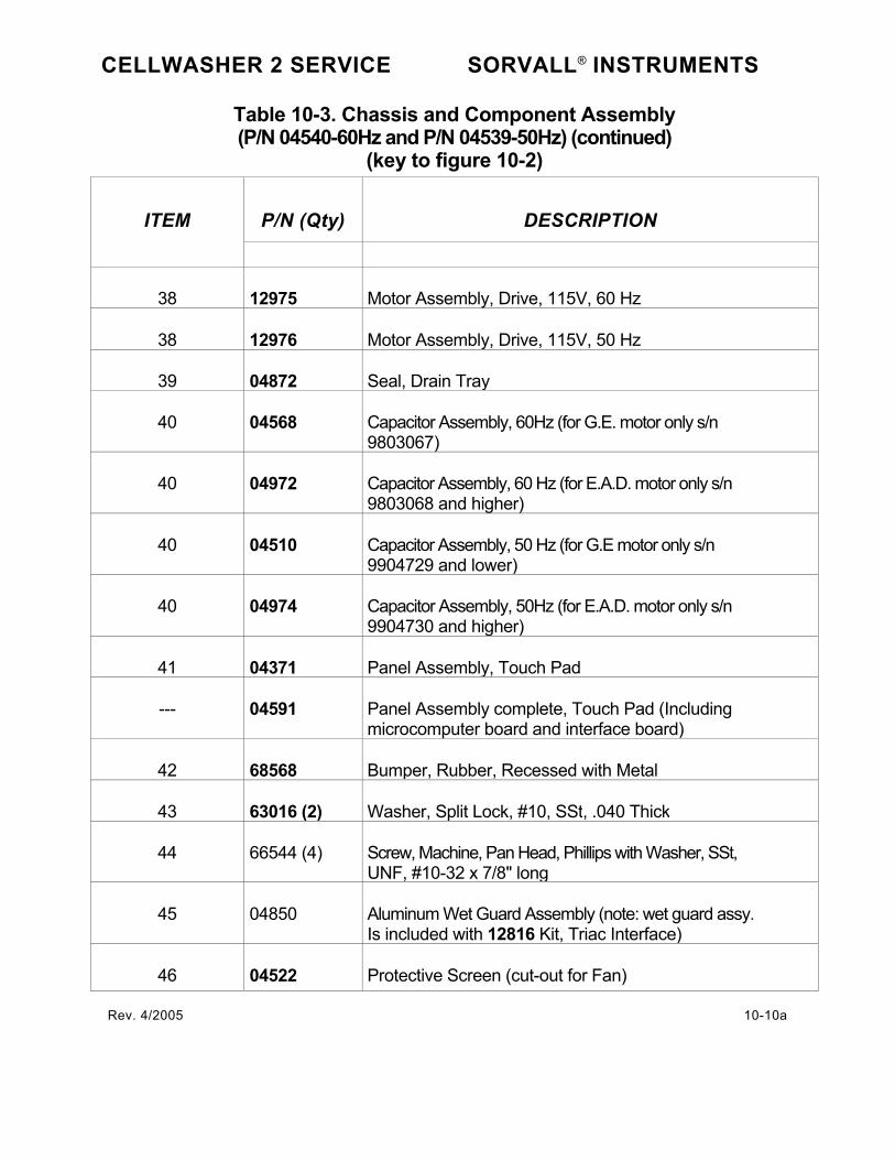
CELLWASHER 2 SERVICE SORVALL® INSTRUMENTS
Table 10-3. Chassis and Component Assembly (P/N 04540-60Hz and P/N 04539-50Hz) (continued)
(key to figure 10-2)
P/N (Qty) DESCRIPTION ITEM
38 12975 Motor Assembly, Drive, 115V, 60 Hz
38 12976 Motor Assembly, Drive, 115V, 50 Hz
39 04872 Seal, Drain Tray
40 04568 Capacitor Assembly, 60Hz (for G.E. motor only s/n 9803067)
40 04972 Capacitor Assembly, 60 Hz (for E.A.D. motor only s/n 9803068 and higher)
40 04510 Capacitor Assembly, 50 Hz (for G.E motor only s/n 9904729 and lower)
40 04974 Capacitor Assembly, 50Hz (for E.A.D. motor only s/n 9904730 and higher)
41 04371 Panel Assembly, Touch Pad
--- 04591 Panel Assembly complete, Touch Pad (Including microcomputer board and interface board)
42 68568 Bumper, Rubber, Recessed with Metal
43 63016 (2) Washer, Split Lock, #10, SSt, .040 Thick
44 66544 (4) Screw, Machine, Pan Head, Phillips with Washer, SSt, UNF, #10-32 x 7/8" long
45 04850 Aluminum Wet Guard Assembly (note: wet guard assy. Is included with 12816 Kit, Triac Interface)
46 04522 Protective Screen (cut-out for Fan)
Rev. 4/2005 10-10a

CELLWASHER 2 SERVICE SORVALL® INSTRUMENTS
Table 10-3. Chassis and Component Assembly (P/N 04540-60Hz and P/N 04539-50Hz) (continued)
(key to figure 10-2)
P/N (Qty) DESCRIPTION ITEM
47 04542 Main Harness Assembly
48 04578 Motor Assembly, Pump, 50Hz / 60Hz
49 04517 Guard, Rear Wet, Machined
50 04845 Harness Assembly, Triac- Interface P.C. Board
51 61141 (3) Nut, Hex, SSt, #1/4-20
52 63019 (3) Washer, Split Lock, #1/4, SSt, .047 Thick
53 04865 Bracket Assembly (for G.E. motor only)
53 04881 Bracket Assembly (for E.A.D. motor only)
54 04839 Triac PC Board Assembly
55 980031 Fuse, 1.0 Amp (50 Hz only)
56 980034 Fuse, 1.5 Amp (50 Hz only)
57 92113 Fuse holder (50 Hz only)
58 04374 Adapter Harness (50 Hz only)
Rev. 2/2002 10-10b

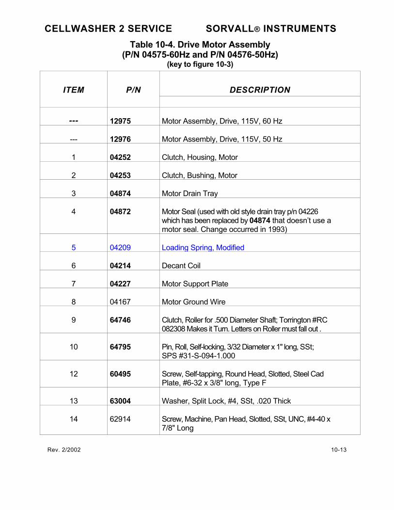
CELLWASHER 2 SERVICE SORVALL® INSTRUMENTS Table 10-4. Drive Motor Assembly
(P/N 04575-60Hz and P/N 04576-50Hz) (key to figure 10-3)
DESCRIPTION ITEM P/N
--- 12975 Motor Assembly, Drive, 115V, 60 Hz
--- 12976 Motor Assembly, Drive, 115V, 50 Hz
1 04252 Clutch, Housing, Motor
2 04253 Clutch, Bushing, Motor
3 04874 Motor Drain Tray
4 04872 Motor Seal (used with old style drain tray p/n 04226 which has been replaced by 04874 that doesn’t use a motor seal. Change occurred in 1993)
5 04209 Loading Spring, Modified
6 04214 Decant Coil
7 04227 Motor Support Plate
8 04167 Motor Ground Wire
9 64746 Clutch, Roller for .500 Diameter Shaft; Torrington #RC 082308 Makes it Turn. Letters on Roller must fall out .
10 64795 Pin, Roll, Self-locking, 3/32 Diameter x 1" long, SSt; SPS #31-S-094-1.000
12 60495 Screw, Self-tapping, Round Head, Slotted, Steel Cad Plate, #6-32 x 3/8" long, Type F
13 63004 Washer, Split Lock, #4, SSt, .020 Thick
14 62914 Screw, Machine, Pan Head, Slotted, SSt, UNC, #4-40 x 7/8" Long
Rev. 2/2002 10-13

CELLWASHER 2 SERVICE SORVALL® INSTRUMENTS
Table 10-4. Drive Motor Assembly (P/N 04575-60Hz and P/N 04576-50Hz)
(key to figure 10-3)
P/N (Qty) DESCRIPTION ITEM
15 60448 Washer, Split Lock, #1/4 X .045 Thick, Steel Cad Plate
16 61258 Screw, Cap, Hex Head, Steel Cad Plate, UNC, #1/4-20 x 5/8" Long
17 90983 Shock Mount, 1" Diameter x .75 Long 1/4-20; 60 Hz Only
17 67813 Shock Mount, 1” Diameter x .75 Long 1/4-20; 50Hz only
18 61141 Nut, Hex, SSt, #1/4-20
19 04287 Motor Drive Ring Subassembly Kit (Includes 5/64 hex key cut short for removal and installation)
20 61948 Washer, Flat, Nylon, .203 ID x .437 OC x .010 Thick
21 61257 Screw, Machine, Round Head, Slotted SSt, UNC, #6 32 x 3/16" Long l
22 61864 (2) Contact, Pin, Electrical Connector, Male 14-20 AWG; Molex #1190
23 61862 Connector Body, Plug, Electrical, 9-Position, Nylon, No Meeting Ears; Molex #03-09-2092
24 67669 Connector Body, Electrical, 3-Position, Nylon; Molex #03-09-2032
25 04260 Vane, Motor Cooling
Rev. 4/2005 10-14a

CELLWASHER 2 SERVICE SORVALL® INSTRUMENTS
Table 10-4. Drive Motor Assembly (P/N 04575-60Hz and P/N 04576-50Hz)
(key to figure 10-3)
DESCRIPTION ITEM P/N
26 60930 Screw, Machine, Pan Head, Slotted, SSt, UNC, #6-32 X ¼ Long
27 62021 Washer, Split Lock, Medium, #6, .031 Thick, 047 Section Width
28 04278 Washer, Shim, .005 Thick
29 04279 Washer, Shim, .010 Thick
30 04286 Spacer, 3/8” ID x 5/8 OD x .024 Thick
Rev. 2/2002 10-14b


DECONTAMINATION CERTIFICATE
Instructions on the reverse of this card must be completed before
field service or the return of the instrument or part to the Sorvall
service facility.
NAME__________________________ DEPARTMENT___________
INSTITUTION______________________ ADDRESS_____
CITY___________________________ STATE__________ ZIP
INSTRUMENT______________________ SERIAL NUMBER________
ROTOR________________________ SERIAL NUMBER________
PART___________________________ PART NUMBER
_________
CONTAMINATE USED__________________________
DECONTAMINATION CERTIFIED BY ___________________
DATE DECONTAMINATED ________________________
DECONTAMINATION CERTIFICATE
Instructions on the reverse of this card must be completed before
field service or the return of the instrument or part to the Sorvall
service facility.
NAME__________________________ DEPARTMENT___________
INSTITUTION______________________ ADDRESS_____________
CITY___________________________ STATE__________ ZIP
INSTRUMENT_______________________ SERIAL NUMBER________
ROTOR__________________________ SERIAL NUMBER________
PART___________________________ PART NUMBER
_________
CONTAMINATE USED__________________________
DECONTAMINATION CERTIFIED BY___________________
DATE DECONTAMINATED ________________________
DECONTAMINATION CERTIFICATE
Instructions on the reverse of this card must be completed before
field service or the return of the instrument or part to the Sorvall
service facility.
NAME__________________________ DEPARTMENT___________
INSTITUTION______________________ ADDRESS_____________
CITY___________________________ STATE__________ ZIP
INSTRUMENT_______________________ SERIAL NUMBER ________
ROTOR________________________ SERIAL NUMBER________
PART__________________________ PART NUMBER
_________
CONTAMINATE USED_________________________
DECONTAMINATION CERTIFIED BY__________________
DATE DECONTAMINATED ________________________

INSTRUCTIONS
l/hen an instrument that has been used with radioactive or pathogenic
laterial requires servicing by Sorvall personnel either at the customer's
iboratory or at Sorvall facilities, the following procedure must be corn-
lied with to insure safety of our personnel:
1. The instrument or part to be serviced shall be cleaned of all blood
and other encrusted material and decontaminated prior to servic¬
ing by our representative. No radioactivity shall be detectable by
survey equipment.
2. A Decontamination Information Certificate shall be completed and
attached to the instrument or part.
: an instrument or part to be serviced does not have a Decontamination
iformation Certificate attached to it, and, in our opinion, the instrument
'r part presents a potential radioactive or biological hazard, our repre-
entative will not service the equipment until proper decontamination
,nd certification has been completed. If an instrument is received at our
Service facilities and, in our opinion, is a radioactive or biological hazard,
the sender will be contacted for instructions as to disposition of the
equipment. Disposition costs will be borne by the sender.
Decontamination Information Certificates are included with these Opera¬
tion Instructions. Additional certificates are available from your local
technical or customer service representative. In the event these certifi¬
cates are not available, a written statement certifying that the instrument
or part has been properly decontaminated and outlining the procedures
used will be acceptable.
NOTE
Service representatives will indicate on a Customer
Service Repair Report if decontamination was required,
and if so, what the contaminate was and what procedure
was used. If no decontamination was required, it should
be so stated. 4/97
INSTRUCTIONS
Vhen an instrument that has been used with radioactive or pathogenic
riaterial requires servicing by Sorvall personnel either at the customer's
iboratory or at Sorvall facilities, the following procedure must be com-
ilied with to insure safety of our personnel:
1. The instrument or part to be serviced shall be cleaned of all blood
and other encrusted material and decontaminated prior to servic¬
ing by our representative. No radioactivity shall be detectable by
survey equipment.
2. A Decontamination Information Certificate shall be completed and
attached to the instrument or part.
f an instrument or part to be serviced does not have a Decontamination
^formation Certificate attached to it, and, in our opinion, the instrument
ir part presents a potential radioactive or biological hazard, our repre-
.entative will not service the equipment until proper decontamination
ind certification has been completed. If an instrument is received at our
Service facilities and, in our opinion, is a radioactive or biological hazard,
the sender will be contacted for instructions as to disposition of the
equipment. Disposition costs will be borne by the sender.
Decontamination Information Certificates are included with these Opera¬
tion Instructions. Additional certificates are available from your local
technical or customer service representative. In the event these certifi¬
cates are not available, a written statement certifying that the instrument
or part has been properly decontaminated and outlining the procedures
used will be acceptable.
NOTE
Service representatives will indicate on a Customer
Service Repair Report if decontamination was required,
and if so, what the contaminate was and what procedure
was used. If no decontamination was required, it should
be so stated. ,1/07
INSTRUCTIONS
Vhen an instrument that has been used with radioactive or pathogenic
naterial requires servicing by Sorvall personnel either at the customer's
aboratory or at Sorvall facilities, the following procedure must be com-
>lied with to insure safety of our personnel:
1. The instrument or part to be serviced shall be cleaned of all blood
and other encrusted material and decontaminated prior to servic¬
ing by our representative. No radioactivity shall be detectable by
survey equipment.
2. A Decontamination Information Certificate shall be completed and
attached to the instrument or part.
f an instrument or part to be serviced does not have a Decontamination
nformation Certificate attached to it, and, in our opinion, the instrument
>r part presents a potential radioactive or biological hazard, our repre-
.entative will not service the equipment until proper decontamination
ind certification has been completed. If an instrument is received at our
Service facilities and, in our opinion, is a radioactive or biological hazard,
the sender will be contacted for instructions as to disposition of the
equipment. Disposition costs will be borne by the sender.
Decontamination Information Certificates are included with these Opera¬
tion Instructions. Additional certificates are available from your local
technical or customer service representative. In the event these certifi¬
cates are not available, a written statement certifying that the instrument
or part has been properly decontaminated and outlining the procedures
used will be acceptable.
NOTE
Service representatives will indicate on a Customer
Service Repair Report if decontamination was required,
and if so, what the contaminate was and what procedure
was used. If no decontamination was required, it should
be so stated. ^

AUSTRIA
Kendro Laboratory Products GmbH
WiefelestraBe 4
A-1230Wien
Tel.: 43(1)80140-0
Fax: 43(1)80140-40
e-mail: [email protected]
FRANCE
Kendro Laboratory Products
B.P. 244, Pare Hightec 6
Batiment Ie Meridien
9 Avenue du Canada
Paris
F-91944 COURTABOEUF Cedex
Tel.: 33(1)69187777
Fax: 33(1)60920034
e-mail: [email protected]
GERMANY
Kendro Laboratory Products GmbH
Heraeusstrasse 12-14
D-63450 Hanau
Tel.: 49(6181)35-300
Fax: 49(6181)35-6944
e-mail: [email protected]
ITALY
AHSI S.p.A.
Via dei Chiosi, 11
1-20040 Cavenago Brianza (Milan)
Tel.: 39(2)950811
Fax: 39(2)95081277
e-mail: [email protected]
POLAND
Heraeus Sp. zo.o.
ul. Duchnicka 3
PL-01-796 Warszawa
Tel.: 48(22)6634323
Fax: 48(22)6634325
e-mail; [email protected]
SWEDEN
Kendro Laboratory Products AB
Hagangsvagen 32
S-19445 Upplands Vasby
Tel.: 46 (8) 59 07 21 90
Fax: 46(8)59031600
e-mail: [email protected]
SWITZERLAND
Kendro Laboratory Products AG
Raffelstrasse 32-Postfach
CH-8045 Zurich
Tel.: 41(1)4541212
Fax: 41(1)4541299
e-mail: [email protected]
UNITED KINGDOM
Kendo Laboratory Products Limited
Stortford Hall Park
Bishop's Stortford
Hertfordshire CM23 5GZ
Tel.: 44(1279)827700
Fax: 44(1279)827750
e-mail: [email protected]
Other EUROPE, MIDDLE EAST,
or AFRICA:
Kendro Laboratory Products GmbH
Heraeusstrasse 12-14
D-63450 Hanau
GERMANY
Tel.: 49(6181)35-300
Fax: 49(6181)35-5944
e-mail: [email protected]
AUSTRALIA
Kendro Laboratory Products Pty. Ltd.
Building 4,2-6 Orion Road
Lane Cove, Sydney, NSW 2066
Tel.: 61(2)99361540
Fax: 61 (2) 9427 9765
e-mail: [email protected]
CHINA, BEIJING:
INSTEC-Kendro Beijing Service Station
Room N1203, Jing Bao Garden
183 An Ding Men Wai St.
Beijing 100011, P. R.China
Tel: 86(10)6426-2609
Fax: 86(10)6426-2765
e-mail: [email protected]
CHINA, HONG KONG:
Kendro Laboratory Products (H.K.) Limited
Room 305, Wing On Plaza
62 Mody Road
Tsimshatsui East, Kowloon
Hong Kong, S.A.R. China
TeL: (852)2142-3910
Fax: (852)2711-3858
CHINA, SHANGHAI:
INSTEC-Kendro Shanghai Service Station
Room 22G, Hui Jia Building
No. 41 Cao Xi Bei Lu
Shanghai 200030, P.R. China
Tel.: 86(21)5490-0216
Fax: 86(21)5490-0230
e-mail: [email protected]
INDIA
Kendro Laboratory Products (India) Pvt. Ltd.
B-5/75 (LGF) Safdarjung Enclave
New Delhi, IND-110029
Tel.: 91(11)6184840
Fax: 91(11)6185397
e-mail: [email protected]
Other ASIA PACIFIC:
Kendro Laboratory Products (H.K.) Limited
Room 305, Wing On Plaza
62 Mody Road
Tsimshatsui East, Kowloon
Hong Kong, S.A.R. China
Tel.: (1352)2142-3910
Fax: (852)2711-3858
CANADA
Kendro Laboratory Products
31 Pecks Lane
Newtown, CT 06470-2337
U.S.A.
Tel.: (203) 270-2080
Fax: (203)270-2166
e-mail: [email protected]
UNITED STATES Of AMERICA
Kendro Laboratory Products
31 Pecks Lane
Newtown, CT 06470-2337
Tel.: (800) 522-7746 toll-free
Fax: (203)270-2166
(203)270-2115
(203)270-2110
e-mail: [email protected]
Other countries, including
LATIN AMERICA:
Kendro Laboratory Products
31 Pecks Lane
Newtown, CT 06470-2337
U.S.A.
Tel.: (203) 270-2080
Fax: (203)270-2210
(203)270-2166
e-mail: [email protected]
Or contact a local representative for SORVALL* brand products. Visit our web site at http://www.lwinlro.com or http://www.kendro.de
SORVALL:
RBV.7/W
•(Kendro
Laboratory Products