Cellular behavior after mechanical stimulation on ... · Cellular behavior after mechanical...
74
Cellular behavior after mechanical stimulation on biofunctionalized polylactic acid nanofibers for tendon tissue engineering 1 Abstract Recently, tissue engineered solutions have been investigated to cure rotator cuff tears, whose curing is often long and painful. Scaffolds mimicking the natural structure and composition of natural tendons have been found to be a promising alternative. Tendons are typically composed of aligned collagen nanofibers on which tendon cells called tenocytes lay and produce their extracellular matrix. As a consequence, electrospinning was chosen as a technique to produce aligned nano-scaled fibers of poly(lactic acid), a biocompatible polymer. In the next steps, the surface of the fibers was functionalized with collagen and the resulting scaffolds were seeded with tenocytes isolated from tendon biopsies. The behavior of the cells was evaluated with and without mechanical stimulation of the scaffolds. First, the fibers were mechanically characterized and their diameter was indeed calculated to be in the nano-range, proving the efficiency of the electrospinning. The functionalization process was also characterized. Collagen immunofluorescence showed that covalent bonding of collagen on the fibers with carbodiimide chemistry (EDC/NHS) was more effective than the physical adsorption of collagen. Later, tenocytes isolated from a tendon biopsy were seeded on functionalized and non- functionalized scaffolds as well as on glass and a cells immunofluorescence was performed to verify the attachment of the cells on the different substrates. The area of the cells was higher on glass than on other substrates, however the cells were much more elongated on fibrous scaffolds and were all aligned in a single direction. It is very likely that the cells aligned along the fibers direction which would demonstrate that the scaffolds had a positive effect on the cells. Indeed, this cellular behavior is very close to what can be observed on natural tendons. The influence of collagen functionalized on the scaffolds was yet not clear. Although cells had a higher area and elongation on the first day of culture on functionalized scaffolds, the values of non-functionalized scaffolds became extremely similar after the third day of culture. A stimulation test on a scaffold seeded with tenocytes had to be ended prematurely due to experimental issues. The sample eventually was 75% stiffer but its yield strain was four times lower. Physical ageing was considered as the most consistent explanation over collagen production on a short stimulation period.
Transcript of Cellular behavior after mechanical stimulation on ... · Cellular behavior after mechanical...

Cellular behavior after mechanical stimulation on biofunctionalized polylactic acid nanofibers for tendon tissue engineering
1
Abstract
Recently, tissue engineered solutions have been investigated to cure rotator cuff tears,
whose curing is often long and painful. Scaffolds mimicking the natural structure and
composition of natural tendons have been found to be a promising alternative. Tendons are
typically composed of aligned collagen nanofibers on which tendon cells called tenocytes lay
and produce their extracellular matrix. As a consequence, electrospinning was chosen as a
technique to produce aligned nano-scaled fibers of poly(lactic acid), a biocompatible polymer.
In the next steps, the surface of the fibers was functionalized with collagen and the resulting
scaffolds were seeded with tenocytes isolated from tendon biopsies. The behavior of the cells
was evaluated with and without mechanical stimulation of the scaffolds.
First, the fibers were mechanically characterized and their diameter was indeed
calculated to be in the nano-range, proving the efficiency of the electrospinning. The
functionalization process was also characterized. Collagen immunofluorescence showed that
covalent bonding of collagen on the fibers with carbodiimide chemistry (EDC/NHS) was
more effective than the physical adsorption of collagen.
Later, tenocytes isolated from a tendon biopsy were seeded on functionalized and non-
functionalized scaffolds as well as on glass and a cells immunofluorescence was performed to
verify the attachment of the cells on the different substrates. The area of the cells was higher
on glass than on other substrates, however the cells were much more elongated on fibrous
scaffolds and were all aligned in a single direction. It is very likely that the cells aligned along
the fibers direction which would demonstrate that the scaffolds had a positive effect on the
cells. Indeed, this cellular behavior is very close to what can be observed on natural tendons.
The influence of collagen functionalized on the scaffolds was yet not clear. Although cells
had a higher area and elongation on the first day of culture on functionalized scaffolds, the
values of non-functionalized scaffolds became extremely similar after the third day of culture.
A stimulation test on a scaffold seeded with tenocytes had to be ended prematurely
due to experimental issues. The sample eventually was 75% stiffer but its yield strain was
four times lower. Physical ageing was considered as the most consistent explanation over
collagen production on a short stimulation period.

Cellular behavior after mechanical stimulation on biofunctionalized polylactic acid nanofibers for tendon tissue engineering
2

Cellular behavior after mechanical stimulation on biofunctionalized polylactic acid nanofibers for tendon tissue engineering
3
Table of contents Abstract ...................................................................................................................... 1
Table of contents ....................................................................................................... 3
Glossary ..................................................................................................................... 5
1 Introduction ....................................................................................................... 7
1.1 Introduction to tissue engineering .................................................................. 7
1.2 Rotator cuff tears ............................................................................................ 8
1.3 State of the art of tendon tissue engineering .................................................. 9
1.4 Description of the project .............................................................................. 12
2 Theoretical background ................................................................................... 13
2.1 Generalities about tendons .......................................................................... 13
2.1.1 Structure and composition of tendons ............................................................ 13
2.1.2 Tendon cells and mechanotransduction ......................................................... 14
2.1.3 Mechanics of tendons .................................................................................... 15
2.2 Biomaterials ................................................................................................. 17
2.2.1 Generalities about biomaterials ..................................................................... 17
2.2.2 Polylactic acid ................................................................................................ 18
2.3 Polymeric fibers ............................................................................................ 22
2.3.1 Electrospinning process ................................................................................. 22
2.3.2 Electrospinning parameters ........................................................................... 23
2.3.3 Characteristics of polymeric fibers ................................................................. 25
2.4 Functionalization process ............................................................................. 26
2.4.1 Hydrolysis of the PLA surface ........................................................................ 26
2.4.2 Covalent attachment of collagen .................................................................... 27
3 Materials and methods .................................................................................... 29
3.1 Preparation of the polymer solution .............................................................. 29
3.2 Production of nanofibers via electrospinning ................................................ 29
3.3 Fibers characterization ................................................................................. 30
3.3.1 Fibers diameter .............................................................................................. 30
3.3.2 Porosity of the fibrous scaffolds ..................................................................... 30
3.3.3 Thickness of the electrospun mat .................................................................. 31
3.3.4 Mechanical properties of the scaffolds ........................................................... 31
3.4 Surface hydrolysis ........................................................................................ 33
3.5 Activation of the carboxylic groups ............................................................... 33
3.6 Covalent attachment of collagen type I ........................................................ 34

Cellular behavior after mechanical stimulation on biofunctionalized polylactic acid nanofibers for tendon tissue engineering
4
3.7 Collagen immunofluorescence..................................................................... 35
3.8 Micro BCA protein assay ............................................................................. 35
3.9 Mechanical properties of functionalized scaffolds ........................................ 36
3.10 Cell culture of MSC and tenocytes ........................................................... 37
3.10.1 Cell types and mediums composition .............................................................. 37
3.10.2 Unfreezing cells .............................................................................................. 38
3.10.3 Changing culture medium ............................................................................... 38
3.10.4 Trypsinization and freezing cells ..................................................................... 39
3.11 Cell seeding on scaffolds .......................................................................... 39
3.12 Live cell staining ....................................................................................... 40
3.13 Cells immunofluorescence ....................................................................... 40
3.14 Mechanical stimulation of seeded scaffolds ............................................. 41
4 Results and discussion ................................................................................... 43
4.1 Fibers characterization ................................................................................ 43
4.1.1 Fibers alignment and presence of beads ....................................................... 43
4.1.2 Properties of the electrospun fibrous mat ....................................................... 44
4.1.3 Mechanical properties of the scaffolds ........................................................... 44
4.2 Effect of the hydrolysis step ......................................................................... 48
4.2.1 On the appearance of the fibers ..................................................................... 48
4.2.2 On the diameter of the fibers .......................................................................... 50
4.3 Collagen immunofluorescence..................................................................... 51
4.4 Collagen concentration with micro BCA assa .............................................. 52
4.5 Mechanical properties of functionalized scaffolds ........................................ 52
4.6 Live cell staining for cellular viability ............................................................ 54
4.7 Cells immunofluorescence ........................................................................... 55
4.8 Mechanical stimulation of seeded scaffolds ................................................. 62
5 Conclusions ..................................................................................................... 65
6 Future perspectives ......................................................................................... 67
Cost of the project .................................................................................................. 69
Environmental impact ............................................................................................ 70
7 References ....................................................................................................... 71

Cellular behavior after mechanical stimulation on biofunctionalized polylactic acid nanofibers for tendon tissue engineering
5
Glossary
BCA: Bicinchoninic Acid
BSA: Bovine Serum Albumin
DAPI: 4',6-diamidino-2-phenylindole
DMSO: Dimethylsulfoxide
DPBS: Dulbecco’s Phosphate Buffered Saline
EDC: 1-ethyl-3-(-3-dimethylaminopropyl) carbodiimide hydrochloride
FBS: Fetal Bovine Serum
MSC: Mesenchymal Stem Cells
NHS: N-hydroxysuccinimide
PBS: Phosphate Buffered Saline
PDLLA: Poly(DL-Lactide)
PFA: Paraformaldehyde
PLA: Poly(Lactide) or Poly(Lactic Acid). To simplify, PLA will be used in the Materials and
methods part as well as in the Results and discussion part to mention the polymer fibers used
in this project (fibers of Poly(L-Lactide-co-DL-Lactide) 70/30)
PLDLA: Poly(L-Lactide-co-DL-Lactide)
PLGA: Poly(L-Lactic -co-Glycolic Acid)
PLLA: Poly(L-Lactide) or Poly(L-Lactic Acid)
PVA: Poly(Vinyl Alcohol)
SEM: Scanning Electron Microscopy
TE: Tissue engineering
TFE: 2,2,2-trifluoroethanol

Cellular behavior after mechanical stimulation on biofunctionalized polylactic acid nanofibers for tendon tissue engineering
6

Cellular behavior after mechanical stimulation on biofunctionalized polylactic acid nanofibers for tendon tissue engineering
7
1 Introduction
1.1 Introduction to tissue engineering
The term “tissue engineering” (TE) was first used at a National Science Foundation (NSF)
sponsored meeting in 1987. It was later defined as “the application of principles and methods
of engineering and life sciences toward fundamental understanding and development of
biological substitutes to restore, maintain and improve human tissue functions” [1]. This
definition embraces methods where the biological substitutes are cells that may be implanted
on a scaffold such as natural collagen or as synthetic and biocompatible polymers to form a
newly grown tissue.
Besides having applications for enhancing the curing of certain diseases, in which the
tissue is grown inside a patient or outside a patient after transplantation, this field can be an
efficient diagnostic tool where the tissue is made in vitro and can be used for testing toxicity,
pathogenicity or drug uptake. [2]
Tissue engineering is a multidisciplinary field whose research includes various areas
such as:
Biomaterials: providing physical and chemical characteristics to improve and direct
the proliferation, the growth or the differentiation of cells in order to form a functional
tissue.
Cellular science: giving methodologies to attest for the proliferation or the
differentiation of cells and providing appropriate knowledge concerning the type of
cells to be used.
Biomechanical design: providing knowledge about properties of native tissues such as
their composition in order to attest for the efficacy and safety of engineered tissues. [2]
Tissue Engineering is a fast expanding field of applied biology and biomedical
engineering that aims to create artificial organs for transplantation, basic research, or drug
development. Therefore it is needed to integrate knowledge of organic chemistry, cell
biology, genetics, mechanics and transport processes to create functional tissue engineered
constructs.

Cellular behavior after mechanical stimulation on biofunctionalized polylactic acid nanofibers for tendon tissue engineering
8
Some tissue engineering methods are now in medical use. Among them, skin tissue
replacement for ulcerations and scaffolds allowing a slow release of anticancer agents to
combat a form of brain cancer. The research goes on to develop new methods, in the fields of
bone tissue engineering or tendon tissue engineering for instance. [1]
1.2 Rotator cuff tears
In this project, the attention will mainly be focused on rotator cuff tendons tears. The
rotator cuff is a group of four muscles and four tendons that act to stabilize the shoulder. The
muscles comprised in the rotator cuff are the Supraspinatus, the Infraspinatus, the
Subscapularis and the Teres minor muscles. These muscles are linked to the head of the
humerus via four tendons.
Rotator cuff tears are some of the most common injuries affecting shoulders, with
more than 75 000 repair procedures every year in the United States [3]. In that case, tendons
are torn and this can affect the mobility of the whole arm. This condition occurs mostly as a
consequence of aging or in some cases, intense activity of the shoulder with sport for instance.
The Supraspinatus tendon is the most frequently torn due to its position in the shoulder.
Rotator cuff tears can be divided in two categories: partial tears and complete tears, crossing
the whole tendon from one side to another. An example of a partial rotator cuff tear is shown
on Figure 1.1.
Figure 1.1: Example of partial rotator cuff tear on the supraspinatus tendon. [3]

Cellular behavior after mechanical stimulation on biofunctionalized polylactic acid nanofibers for tendon tissue engineering
9
Operative and non-operative treatments exist for rotator cuff tears. The non-operative
treatment is based on rest of the arm in the first place. After the inflammation is gone, the
patient can start a gentle range-of-motion program to maintain a good mobility and range of
motion of the arm. As soon as the pain is gone, the patient starts a strengthening program in
order to restore the full power of the tendon.
On the other side, the operative treatment is called arthroscopy. Small tools are
inserted via small incisions that make it possible for the surgeon to reinsert rotator cuff
tendons. This treatment is less time-consuming and is recommended for younger and active
patients. In every way, the treatment never allows the tendons to recover their full strength
and chronic tears are extremely frequent. Failures as high as 94% have been reported after
primary repair of chronic cuff injuries.
1.3 State of the art of tendon tissue engineering
Since the recovery in the case of tendon tears is long and painful, it is of primary
importance to improve the healing of such conditions. For this purpose, tissue engineered
solutions are being investigated. These studies focus on various scaffolds able to support
cellular adhesion, proliferation and sometimes differentiation. The ultimate goal of these
projects is the production of extracellular matrix with sufficient mechanical properties to be
able to replace torn tendons. [4]
As tendons are mostly made of collagen, some studies started using gel-collagen
sponges as scaffolds and examined the effect of MSC post-surgery. Juncosa-Melvin et al.
seeded mesenchymal stem cells (MSC) on collagen sponges and compared them to acellular
sponges [5]. These scaffolds were implanted in rabbit tendons containing defects and the
scaffolds were analyzed after 12 weeks post-surgery. Mechanical properties for the cellular
scaffolds were between 50% and 75% those of a healthy tendon whereas the mechanical
properties for the acellular scaffolds were twice as low. Moreover, both repairs showed
staining for key proteins as well as good cellular alignment. In brief, these scaffolds showed
good mechanical properties and histology and gave very promising results.
Juncosa-Melvin et al also studied the influence of the cell-to collagen ratio on the
biomechanics and histology of the repair [6]. They implanted seeded tissue engineered

Cellular behavior after mechanical stimulation on biofunctionalized polylactic acid nanofibers for tendon tissue engineering
10
constructs in rabbit tendon defects, using different cell-to-collagen ratios and different seeding
densities. The repairs were assigned for biomechanical and histological analyses after 12
weeks post-surgery. They concluded from this study that high cell-to-collagen ratios do not
improve biomechanics or histological appearance of the repairs. Lower cell-to-collagen ratios
showed no formation of ectopic bone and similar biomechanics and histology.
More recent studies emphasized new ideas for tissue-engineered constructs for tendons
repairs. It is now known that cells can sense the mechanical efforts undergone by tendons. As
a consequence, to recreate in vivo conditions, the effect of mechanical stimulation on the
scaffolds has been studied by Abousleiman et al [7]. MSC were seeded on decellularized
human umbilical vein embedded in collagen gel and stimulated the construct with a
mechanical stimulator. The stimulation took place during up to 2 weeks and the results were
compared with non-stimulated constructs. The results were quite promising since the
stimulated constructs showed way higher (more than twice as high) mechanical properties as
well as increased cell number. Moreover, the cells demonstrated parallel alignment with the
collagen fibers and cellular morphology close to the native tendons. Their results proved that
mechanical stimulation has a very positive effect on the mechanical properties of the
constructs as well as on the cellular behavior.
Pursuing in an effort to increase the mechanical properties of the scaffolds, new
studies investigated the effect of scaffold stiffening. According to the previous results,
increasing the mechanical properties of the constructs could have a positive effect on the
repairs biomechanics. For this purpose, Nirmalanandhan et al. created collagen type I sponges
stiffened by crosslinking and seeded MSC [8]. Crosslinking lead to a high increase in the
mechanical properties of the sponges. The constructs were then stimulated with a mechanical
stimulator using two different frequencies (100 cycles/day and 3000 cycles/day). The results
were compared with non-crosslinked stimulated samples. Surprisingly, non-crosslinked
constructs showed higher mechanical properties than the crosslinked constructs. Moreover, no
significant difference was observed between the two stimulation intensities. These results
were explained by the fact that the scaffolds were stiff to such an extent that the cells could
not sense the mechanical stimulation. This phenomenon is called stress shielding: the material
absorbs all the mechanical energy without transferring it to the cells. This study helped to

Cellular behavior after mechanical stimulation on biofunctionalized polylactic acid nanofibers for tendon tissue engineering
11
design future scaffolds in the sense that they must be stiff enough to handle the mechanic
efforts but not too stiff to avoid stress shielding.
Creating polymer fibrous scaffolds can also mimic the natural structure of tendons.
The electrospinning technique allows the fabrication of such scaffolds since it is able to create
aligned nanofibers with a similar size to the collagen fibers in tendons. Moffat et al. designed
poly(L-lactic-co-glycolic acid) (PLGA) nanofibers scaffolds via electrospinning and seeded
human fibroblasts in order to attest for the cellular behavior of the cells on the scaffolds.
They also compared the cellular behavior on aligned and unaligned scaffolds [9]. The
analyses showed that cells attached along the nanofibers axis on aligned scaffolds where cells
did not show a preferential orientation on randomly oriented scaffolds. Moreover, cell
alignment; distribution and matrix deposition were higher in the case of aligned scaffolds as
well as mechanical properties that were naturally higher. This study proved that aligned
nanofibers scaffolds could recreate the natural architecture of the tendons and be used as
scaffolds for tendon tissue engineering.
Different fibers organization and polymers were also considered. These fibrous
polymeric scaffolds were as well tested for cellular differentiation of MSC. Barber et al.
studied the cellular behavior of human MSC on nanofibrous electrospun scaffolds using
poly(L-lactide) (PLLA) [10]. They designed braided nanofibers bundles in order to increase
the mechanical properties of the scaffolds and mimic the actual structure of tendons. Their
results showed that the mechanical properties of the scaffolds were higher for 3-bundle
scaffolds (compared to 4 and 5-bundle). They observed that human MSC adhered and aligned
well along the fiber axis and also that the scaffolds supported cellular proliferation and were
responsible for the upregulation in the expression of key genes. Under mechanical stimulation
with tenogenic growth factors, the human MSC differentiated well into the tenogenic lineage,
proving that these scaffolds provide a good environment for cellular differentiation.
In this trend, Surrao et al. designed aligned electrospun scaffolds using different
polymers: PLGA, poly(L-lactide-co-DL-lactide) (PLDLA) (98kDa and 250kDa), poly(DL-
lactide) (PDLLA) and PLLA [11]. They also introduced a crimp-like pattern as it is present in
natural tendons. All the fibrous scaffolds were mechanically tested and fibroblasts were
seeded. PLDLA scaffolds exhibited the highest modulus and the lowest degradation rate. The

Cellular behavior after mechanical stimulation on biofunctionalized polylactic acid nanofibers for tendon tissue engineering
12
cellular analyses showed good attachment, proliferation and deposition of extracellular matrix
on these PLDLA fibers. The extracellular matrix deposition resembled closely to the
organization of natural tendons. This study proved that PLDLA can be a first choice polymer
for tendon tissue engineering and that mimicking the tendon structure is the key to a good
cellular behavior.
1.4 Description of the project
In this project, a biological graft will be developed using aligned nanofibers scaffolds.
A biodegradable and biocompatible copolymer, poly(L-lactide-co-DL-lactide) 70/30, will be
electrospun with a custom electrospinning device. Properties such as the average fibers
diameter will be characterized. The electrospun fibers will be functionalized with collagen
type I, which is the most abundant protein in the tendon extracellular matrix, using
carbodiimide chemistry. Moreover, the scaffolds will be seeded with tenocytes isolated from a
tendon biopsy. The material-cell construct will be mechanically stimulated to match the in-
vivo conditions and the results will be compared to non-stimulated scaffolds in a mechanical
and histological way. Every step of the process will be accordingly characterized.

Cellular behavior after mechanical stimulation on biofunctionalized polylactic acid nanofibers for tendon tissue engineering
13
2 Theoretical background
2.1 Generalities about tendons
Tendons are soft connective tissues with limited vasculature. Their role is to transmit
mechanical stresses between muscles and bones. Therefore, they play a significant role in
musculoskeletal biomechanics. A good knowledge of tendons structure and functioning is a
must in order to mimic the most efficiently its organization and discuss the results
appropriately. [12]
2.1.1 Structure and composition of tendons
Briefly, tendons are collagenous constructs, which means that collagen is the protein
responsible for the structural integrity of tendons. They are also built in a hierarchical
organization as shown in Figure 2.1: a tendon is made of several fascicles, each fascicle is
made of many fibrils which can be divided in sub-fibrils and micro-fibrils, finally these
micro-fibrils are composed of numerous collagen fibers. This hierarchical configuration
ensures that minor damages do not spread to the entire tendon, providing a very high
structural strength. [12, 13]
Figure 2.1: Hierarchical structure of a tendon [13]

Cellular behavior after mechanical stimulation on biofunctionalized polylactic acid nanofibers for tendon tissue engineering
14
Concerning its composition, a tendon contains approximately 55% to 70% of water.
Between 60% and 85% of its dry weight is composed of collagen organized in crimped fibers.
This crimp feature or waviness gives even more elongation efficiency to the fibers. More than
60% of the whole collagen content is type I collagen organized in fibers composed of two α1
and one α2 chains. The rest of the collagen content is mostly composed of type III collagen
and low percentages of type IV, type V and type VI collagen. Elastin fibers are also present
inside tendons with a percentage of 2% of the dry weight. These fibers provide more elasticity
to the tendons and allow them to resume their initial shape after being stretched. All the
tendon components are surrounded by a proteoglycan matrix, which binds all the fibrous
elements in one cohesive structure. [14]
2.1.2 Tendon cells and mechanotransduction
Collagen and other proteins are synthesized by fibroblasts, the most abundant cells in
tendons. In the case of tendons, these fibroblasts are called tenocytes and are elongated along
the collagen fibers. They lie in longitudinal rows and also have sheet-like extensions far into
the extracellular matrix. Tendons also have actin based cell-cell interaction: actin stress fibers
run along the rows of tenocytes. Moreover, it is now known that tendons have a high
extracellular matrix turnover, meaning that the extracellular matrix is entirely re-created after
a while but also that damaged fibers can be quickly replaced with fresh collagen fibers
produced by tenocytes. [14]
Recent studies have demonstrated that the matrix production rate is also dependent on
the efforts undergone by the tendon. The more intense and the longer the effort is, the higher
the production rate will be. This process is called mechanotransduction: the cells sense
mechanical stresses and the cells adapt accordingly.
This means that a signaling path is created from the extracellular matrix to the inside
of the cells. It is known that integrins play an important role in the mechanotransduction
process. Indeed, integrins are proteins acting as receptors since they are linking the
extracellular matrix to the cytoskeleton of the cells. They create a continuum between the
outside and the inside of the cells. It is well believed that they are acting as sensors for tensile
strains in the same way. They perform an outside-in signaling but also in an inside-out mode.

Cellular behavior after mechanical stimulation on biofunctionalized polylactic acid nanofibers for tendon tissue engineering
15
As a consequence, they are partly responsible for the cellular response to mechanical stresses
such as cells growth, survival, morphology or proliferation. [14]
2.1.3 Mechanics of tendons
Knowing the biomechanics of tendons is also of a great importance to study this
subject. The hierarchical structure and the waviness of tendons fibers play an important role in
their mechanical behavior. Indeed, they exhibit a non-linear behavior to tensile forces. On a
typical stress/strain curve (Figure 2.2), a toe region appears at low forces. This region
corresponds to the uncrimping of the fibers.
Since it is easier to uncrimp the fibers than stretching them, this region has a lower
slope than the elastic zone. The following region is the linear elastic region, followed by the
yield region and finally failure. In general, the mechanical behavior of tendons must be seen
as the individual uncrimping and failure of collagen fibers. Moreover, the hierarchical
structure of tendons gives them a hyperelastic behavior. This is characterized by a low yield
region and a large elastic region, meaning that the material will suffer plastic deformation
only in very extreme cases. [12]
The second important feature is the viscoelastic response of tendons, which means a
time dependent mechanical behavior. In brief, the relationship between stress and strain
depends on the time of displacement or load and this can be seen with two important features
Figure 2.2: Typical curve for a stress-strain test of a tendon, showing the toe
region, the linear region and yield and failure region. [12]

Cellular behavior after mechanical stimulation on biofunctionalized polylactic acid nanofibers for tendon tissue engineering
16
of viscoelasticity: creep and stress relaxation (Figure 2.3). Creep means that, under a constant
load, the deformation increases over time. On the other side, stress relaxation is the decrease
of load under a constant deformation. [12]
Finally, if a viscoelastic material is loaded then unloaded several times, the material
will display energy dissipation. In other words, the curve corresponding to unloading will not
follow the loading curve, and this difference shows the amount of dissipated energy during
the test. During cyclic loadings, the stress-strain curve slightly shifts to increased strains with
each cycle. The curve eventually becomes steady after a certain number of cycles, usually 10
in the case of tendons. [12]
Figure 2.3: Typical curves of a stress relaxation test (left) and a crimp test (right) [12]
Figure 2.4: Stress-strain curves showing energy dissipation after loading-
unloading cycles in a viscoelastic material [12]

Cellular behavior after mechanical stimulation on biofunctionalized polylactic acid nanofibers for tendon tissue engineering
17
2.2 Biomaterials
2.2.1 Generalities about biomaterials
In the early 1900’s, artificial materials were developed to replace various components
of the human body. A biomaterial is now defined as “a non-drug substance suitable for
inclusions in systems which augment or replace the function of bodily tissues or organs”.
These materials must be capable of being in contact with human tissues or fluids without
negative effects or reactions during long periods of time. [15]
These materials can be classified according to their composition, in polymers, metals,
ceramics or composites formed with a combination of different materials. In this report, the
attention will be focused on biopolymers. As any sort of biomaterial, they can also be
classified according to their interaction with human bodies or human fluids.
- Inert biomaterials: there are no interactions between the tissue and the implant,
which also means no response of the tissue in contact with the material. This is the
case of high molecular weight polyethylene for instance. [16]
- Bioactive materials: the material shows the possibility to create bonds with the
surrounding tissues. Polymers are typically not bioactive; bioactive materials are
almost exclusively ceramics materials. [16]
- Resorbable materials: they are deeply incorporated into the surrounding tissue, and
may degrade in order to let freshly grown tissue expand. Polylactic acids, for
instance, are resorbable materials. [16]
Some polymers are also biodegradable (Figure 2.5). A biodegradable material is
defined as a material “capable of undergoing decomposition into carbon dioxide, methane,
water, inorganic compounds and biomass” (according to ASTM standard D-5488-94d and
European norm EN 13432). Testing a material for biodegradation is a complex procedure.
However, the main mechanism is the enzymatic action of microorganisms. The tests are
generally carried under different media: liquid, inert or compost medium and the resulting
products are analyzed. Few rules can be used to attest for the evolution of the biodegradability
of a material, such as the hydrophobicity, the molecular weight or the crystallinity. [17]

Cellular behavior after mechanical stimulation on biofunctionalized polylactic acid nanofibers for tendon tissue engineering
18
Figure 2.5: Classification of biodegradable polymers [17]
2.2.2 Polylactic acid
Polylactic acids or polylactides are aliphatic polyesters commonly used in tissue
engineering. The main advantages of these polymers are their biodegradability and
biocompatibility. The biodegradation process is done by hydrolysis as water diffuses into the
material. The resulting products of the biodegradation are lactic acid and glycolic acid, which
are further metabolized into water and carbon dioxide. The consequence of this hydrolysis is
the breaking of polymer chains, leading to a loss of chemical stability and mechanical
integrity. [18] The main drawbacks of poly(lactic acid) (PLA) are its brittleness and its poor
thermal stability. [19]
Prior to 1950s, it was impossible to achieve high molecular weight polylactic acid.
The key to this improvement had been the discovery of specific products, called lactides,
coming from the controlled depolymerization of low molecular weight polylactic acid. These
lactides can be re-polymerized into high molecular weight polylactic acid in a ring-opening
fashion. [20]

Cellular behavior after mechanical stimulation on biofunctionalized polylactic acid nanofibers for tendon tissue engineering
19
Figure 2.6: Configurations of lactic acid: L-lactic acid (left) and D-lactic acid (right) [21]
Moreover, two configurations, L and D, exist for lactic acid (Figure 2.6). Since
lactides are cyclic diesters, they come with three different configurations: L-lactide, D-lactide
and DL-lactide (or meso-lactide) (Figure 2.7). Poly-L-lactide or PLLA is semi-crystalline and
thus has a low degradation rate: the full degradation can take place over years, depending on
the size. [20] This crystallinity can also lead to not-so-ideal biocompatibility. Copolymers of
L-lactide and D-lactide have then been created in order to increase the degradation rate and
reduce the crystallinity. However, such copolymers lack mechanical properties that are
necessary in certain applications. Poly(DL-lactide) is, on the other hand, an amorphous
polymer with a rather high degradation rate. Copolymers of L-lactide and DL-lactide show
good mechanical properties as well as acceptable degradation rate for tissue engineering
purposes. These properties can obviously be modified changing the proportions of the two
monomers to fit the best to the application. [22]
Figure 2.7: Configurations of lactides: L-lactide (left), Meso-lactide or DL-lactide (center) and D-lactide (right)
[21]
Unlike most polymers needing oil and gas for their monomers to be produced, PLA
can be made without the use of fossil resources. Indeed, lactic acid can be obtained thanks to a
process using annually renewable crops. Starch is produced via photosynthesis: solar energy
is used in order to produce starch from carbon dioxide and water. The produced starch can be
extracted and converted into sugars by an enzymatic hydrolysis process. These sugars are then

Cellular behavior after mechanical stimulation on biofunctionalized polylactic acid nanofibers for tendon tissue engineering
20
transformed into lactic acid after fermentation performed by microorganisms. A direct and
cheap source of glucose can be found in corn which is now widely available. Lactic acid
produced via fermentation is almost exclusively in the L configuration. In order to produce
racemic mixture, a chemical synthesis is necessary. [23] The process of synthesis of lactic
acid is shown in Figure 2.8.
Figure 2.8: Process of synthesis of lactic acid via enzyme hydrolysis of starch produced via photosynthesis then
fermentation of the glucose into lactic acid [21]
The first process used to produce PLA is the direct polycondensation of lactic acid.
However, this process is unable to produce relatively high molecular weight polymers. Thus,
a second route is being used to produce higher molecular weight chains. In the first step, lactic
acid is polymerized via standard polycondensation. This polycondensation leads to low
molecular weight polymers or oligomers. In the next step, dimers called lactides are obtained
thanks to a controlled depolymerization of the oligomers. During this step, water is removed
from the system without the use of solvent then the dimer is purified under vacuum
distillation. In the last step, heat is applied in order to perform the ring-opening
polymerization of the lactides, still without the need of solvent. The purity of the lactides is
extremely important as it will have an influence on the molecular weight of the final polymer.

Cellular behavior after mechanical stimulation on biofunctionalized polylactic acid nanofibers for tendon tissue engineering
21
[24] The whole process for the synthesis of high molecular weight PLA is shown in Figure
2.9.
Figure 2.9: Synthesis of high molecular weight polylactic acid via ring opening polymerization of lactides [21]
Buchatip et al. studied the thermal and mechanical properties of poly(L-lactide-DL-
lactide) containing different mol% of the two monomers. They synthesized these copolymers
by ring opening of the corresponding lactides. As expected, the 70/30 PLDLA copolymer was
entirely amorphous and its glass transition temperature was around 54°C. Concerning
mechanical properties, both the tensile strength and modulus decreased as the percentage of
DL lactide increased. On the other hand, the fraction of DL lactide had the opposite effect on
the elongation at break. As more DL lactide were introduced into the copolymer, the
elongation at break increased and reached an optimal value at 30% DL lactide. As a
consequence, it appears that the copolymer used in this project should be less strong than
standard PLLA but a way higher elongation at break. In the case of polymeric films, the
Young’s modulus was twice as high for PLLA, the tensile strength was nine times higher for
PLLA and the elongation at break was 25 times higher for 70/30 PLDLA. [25]
Lactide

Cellular behavior after mechanical stimulation on biofunctionalized polylactic acid nanofibers for tendon tissue engineering
22
2.3 Polymeric fibers
2.3.1 Electrospinning process
Electrospinning is a method used for the production of nano-scaled to micro-scaled
fibers. It has recently gained interest due to the increasing need of polymer nanofibers
scaffolds for tissue engineering. This process is attractive in the way that it is easy to setup
and quite inexpensive. A custom setup is often used, which shows its simplicity. A second
positive aspect is that it can be used with a wide variety of polymers.
In order to produce fibers from a polymer solution, the process uses an electrical
voltage to draw very fine fibers from a polymer solution. The polymer solution is typically
injected inside a syringe and a voltage is applied at the needle of the syringe. The applied
voltage induces charge within the polymer, creating repulsion forces in the solution. The
electrical forces exceed the surface tension of the solution and create a cone named Taylor’s
cone at the end of the needle. As the solvent evaporates, fibers are formed and cast on a
grounded collector. The whole electrospinning process can be seen in Figure 2.10.
Figure 2.10: Process of fibers production via electrospinning showing the syringe pump, the polymer solution
inside the syringe, the power supply, the collector [26]

Cellular behavior after mechanical stimulation on biofunctionalized polylactic acid nanofibers for tendon tissue engineering
23
2.3.2 Electrospinning parameters
Controlling the process parameters such as the feed rate, the applied voltage, the
polymer concentration is very important to obtain the desired fiber diameter and avoid the
formation of beads. Many parameters will have an influence on the resulting fiber mats. Such
parameters include: the viscosity of the solution (linked to the polymer concentration), the
conductivity of the solution, the feed rate, the applied voltage, the distance between the needle
and the collector as well as the collector composition and its geometry. [27] [28]
First of all, while elaborating the polymer solution to be electrospun, two parameters
can be modified. The first is the concentration of the polymer in the solvent which can also be
considered as the viscosity of the solution. This parameter can have a major importance in
most cases. Correlations have been tried to be found between the concentration and the
intrinsic viscosity of the polymer. However, it has been found that these correlations depend
highly on the type of polymer. [28] For instance, Koshi et al discovered that the product [η]c
(where η is the intrinsic viscosity and c the polymer concentration) must exceed 5 in order to
obtain a solution able to be electrospun. [29] In general, it has been found that increasing the
polymer concentration increases the fibers diameter. For instance, PLLA fibers of less than
300nm were produced with a 1%wt solution whereas a 5%wt solution produced fibers of
diameter higher than 800nm. [27] [28]
The second parameter taking place in the preparation of the solution to be electrospun
is the choice of the solvent and thus the conductivity of the solution. Nonetheless, the choice
of the solvent is mainly driven by the need to effectively dissolve the polymer. It has been
found that a higher conductivity in the solution leads to smoother fibers and the formation of
fewer beads. The addition of salts, such as NaCl, is a common method to increase the
conductivity of the solution and thus, to obtain smooth fibers without beads. [27]

Cellular behavior after mechanical stimulation on biofunctionalized polylactic acid nanofibers for tendon tissue engineering
24
Figure 2.11: SEM photograph showing fibers and beads formed during the electrospinning process inside the
fibrous mat.
The feed rate is the rate at which the polymer solution flows out of the needle. It is
another parameter whose influence has been widely studied. However, its effect on the
diameter of the fibers is not precisely known. A trend indicates that lower flow rates yield
fibers with smaller diameters, but in some cases, no actual influence had been noticed. [28]
An assured observation shows that the feed rate must be high enough to produce fibers. On
the other hand, if this parameter is set too high, the jet will be too thick and the solvent will
not entirely evaporate. This can cause a partial melting of the fibers due to the high
temperature of the solvent as it leaves the needle and leads to the formation of beads. [27]
[28]
In this process, the voltage applied at the needle of the syringe is used to draw polymer
fibers from the solution. It is a key feature of the process and thus, this parameter has also
been studied in many ways. First, it must definitely be high enough to overcome the surface
tension of the solution. The relation between the fibers diameter and the voltage is not clearly
defined. With some polymers like PDLA or poly(vinyl alcohol) (PVA), higher voltages
yielded larger fibers although the opposite effect was observed with other polymers like
bisophenol-A-polysulfone. Still, a common observation proved that very high voltages led to

Cellular behavior after mechanical stimulation on biofunctionalized polylactic acid nanofibers for tendon tissue engineering
25
the formation of many beads inside the fibrous mat. [27] [28] Figure 2.12 shows the
influence of the voltage and the polymer concentration on the fiber diameter in the case of
polycaprolactone.
Figure 2.12: Graph showing the influence of the polymer concentration and the voltage used during
electrospinning on the diameter of polycaprolactone fibers [28]
A particular attention must be paid to the distance between the needle and the
collector. If the collector is too close, the solvent is not entirely evaporated and can cause
melting of the fibers and forms beads. In the opposite case, the fibers might not all reach the
collector, resulting in an important loss of material. [27]
Moreover, the composition of the collector can influence the aspect of the fibers.
Metallic collectors typically lead to smooth fibers whereas porous collectors lead to porous.
Finally, a rotating collector can be used in order to obtain aligned fibers. A stationary
collector will typically lead to random oriented fiber mats. [27]
2.3.3 Characteristics of polymeric fibers
In this project, the choice of electrospun fibers is of primary importance. Indeed,
polymeric fibers offer many advantages over polymeric films for instance. First of all, they
mimic the natural structure of tendons and it is known that cells need a familiar environment
to proliferate. Nanoscaled fibers, moreover, offer even more advantages. Nanofibers have a

Cellular behavior after mechanical stimulation on biofunctionalized polylactic acid nanofibers for tendon tissue engineering
26
very large surface area to volume ratio and a large weight to mechanical properties ratio.
Their surface can also be modified easily according to the desired expectations. All of these
properties are emphasized in this project, making such fibers a first class choice for tendon
tissue engineering.
2.4 Functionalization process
In order to mimic also the composition of the collagen fibers, it is necessary to attach
collagen on the surface of the fibers. This is done in this project thanks to a functionalization
step.
On the one hand, the surface of PLA can be hydrolyzed in order to reveal carboxylic
groups. On the other hand, it is common to take advantage of the primary amino groups
present on proteins such as collagen. The best way to attach such molecules on hydrolyzed
PLA surfaces is using carbodiimide zero-length crosslinkers.
2.4.1 Hydrolysis of the PLA surface
Carboxylic groups must be created on the surface of the PLA fibers. This can be done
with a hydrolysis of the fibers with a strong alkali like sodium hydroxide. The action of the
alkali is to break the polymer chains and to yield a carboxylic group on the end of one chain
(Figure 2.13). The intensity of the hydrolysis can be controlled by modifying the
concentration and the exposition time. The longer the exposition time and the more
concentrated the solution, the more carboxylic groups are formed. However, the hydrolysis
has also a negative effect on the fibers because polymer chains are broken during the step,
possibly decreasing the mechanical properties. As a consequence, it is important to measure
the effect of the hydrolysis and determine an adequate combination of exposition
time/concentration. [30]

Cellular behavior after mechanical stimulation on biofunctionalized polylactic acid nanofibers for tendon tissue engineering
27
Figure 2.13: Example of hydrolysis of a PLA chain and the resulting products
2.4.2 Covalent attachment of collagen
Carbodiimide chemistry and more specifically carbodiimide zero-length crosslinkers are
often used to create amide bonds between carboxylic groups and primary amino groups. This
type of crosslinking is often used to bond proteins like collagen since they contain several
amino groups.[33]
Figure 2.14: Chemical structure of EDC and its molecular weight[32]
The carbodiimide 1-ethyl-3-(-3-dimethylaminopropyl) carbodiimide hydrochloride (EDC)
(Figure 2.14) is the main crosslinker used in such cases. A non-negligible drawback of this
technique is the unstable intermediate formed during the reaction. Indeed, the reaction of EDC
and the carboxylic group forms an active ester, o-acylisourea, which is very reactive towards
primary amines. This intermediate will react with any primary amine group and form an
amide bond between the PLA surface and the collagen molecule. An isourea by-product is
created at the end. A consequence of this is the formation of poly-proteins due to the presence
of several amino groups in proteins. [31] Figure 2.15 shows the action of EDC on the
coupling of a carboxylic acid and a primary amine.

Cellular behavior after mechanical stimulation on biofunctionalized polylactic acid nanofibers for tendon tissue engineering
28
Figure 2.15: Action of EDC coupling of a carboxylic acid with a primary amine [31]
It is necessary to obtain a more stable intermediate in order to avoid this undesirable
effect. The addition of N-hydroxysuccinimide (NHS) (Figure 2.16) has been found to have a
positive effect on the reaction. Indeed, the NHS molecule couples directly to the unstable
intermediate to form a much more stable intermediate that will not produce undesirable
reactions. Moreover, the use of the couple EDC/NHS makes it possible for the reaction to be
carried at physiologic pH or in a phosphate buffered saline solution, while EDC-direct
coupling is only possible at acidic pH.
Figure 2.16: Chemical structure of NHS and its molecular weight [33]

Cellular behavior after mechanical stimulation on biofunctionalized polylactic acid nanofibers for tendon tissue engineering
29
3 Materials and methods
3.1 Preparation of the polymer solution
In this project, the considered polymer is 70/30 L-lactide/DL-lactide copolymer (Purasorb
PLDL 70/30, IV midpoint 3.8 dl/g, Mw=850kDa, © Purac). A 50mL solution of 4% w/v of
polymer in 2,2,2-trifluoroethanol (TFE) was prepared for electrospinning. This polymer has
been chosen for its well-known biocompatibility and biodegradability, which makes it a first
class polymer for tissue engineering applications.
3.2 Production of nanofibers via electrospinning
Figure 3.1: SEM photograph of electrospun PLA fibers
The aligned nanofibers scaffolds were made via the electrospinning technique. This was
carried out thanks to a custom electrospinning setup. The previously mentioned polymer
solution was inserted in a 20mL syringe pump of 20,3mm diameter with a needle of 25GA
(0,5mm) diameter. A voltage of 7,5kV to 10kV was applied at the needle and the polymer
solution was fed at a rate of 0,5mL/h to 1mL/h. A rotating collector at 1000rpm was placed at
13cm from the needle and used for collecting aligned fibers. A 21cm x 28cm mat of polymer
nanofibers was obtained. The 50mL of polymer solution prepared previously were entirely
electrospun.
Cellular behavior after mechanical stimulation on biofunctionalized polylactic acid nanofibers for tendon tissue engineering
30
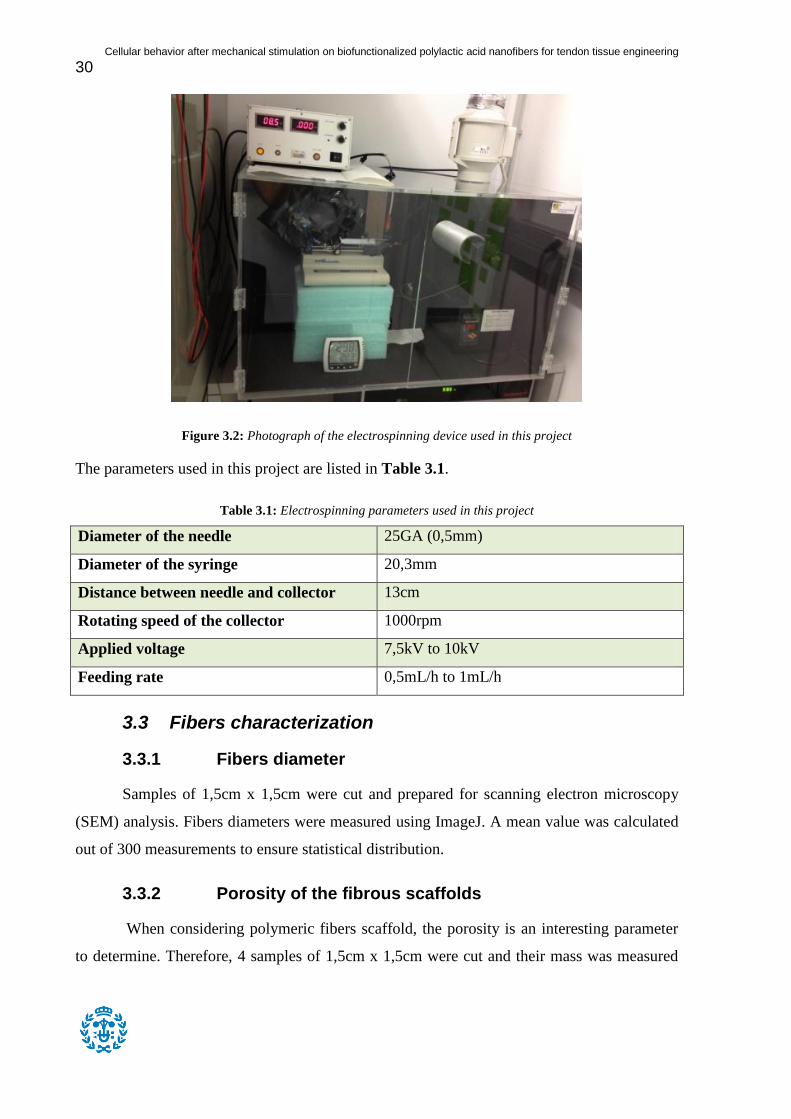
Figure 3.2: Photograph of the electrospinning device used in this project
The parameters used in this project are listed in Table 3.1.
Table 3.1: Electrospinning parameters used in this project
Diameter of the needle 25GA (0,5mm)
Diameter of the syringe 20,3mm
Distance between needle and collector 13cm
Rotating speed of the collector 1000rpm
Applied voltage 7,5kV to 10kV
Feeding rate 0,5mL/h to 1mL/h
3.3 Fibers characterization
3.3.1 Fibers diameter
Samples of 1,5cm x 1,5cm were cut and prepared for scanning electron microscopy
(SEM) analysis. Fibers diameters were measured using ImageJ. A mean value was calculated
out of 300 measurements to ensure statistical distribution.
3.3.2 Porosity of the fibrous scaffolds
When considering polymeric fibers scaffold, the porosity is an interesting parameter
to determine. Therefore, 4 samples of 1,5cm x 1,5cm were cut and their mass was measured

Cellular behavior after mechanical stimulation on biofunctionalized polylactic acid nanofibers for tendon tissue engineering
31
thanks to precision scales. The samples were then entirely dipped in an ethanol solution 70%
and gently mixed during 1h to ensure optimal soaking. After this period, samples were
retrieved from ethanol and weighted. The porosity is given by the following formula:
With the mass difference after and before soaking with ethanol
the initial mass of the samples
Polymer density 1,3g/cm3
Ethanol density 0,869g/cm3
3.3.3 Thickness of the electrospun mat
The thickness of the fibrous mat was calculated according to the following formula.
3.3.4 Mechanical properties of the scaffolds
Mechanical properties of the fibers were tested using a Bose Electroforce 5100
Biodynamic equipped with a 200N load cell installed inside an incubator. Appropriate grips
for fiber mats testing were used.

Cellular behavior after mechanical stimulation on biofunctionalized polylactic acid nanofibers for tendon tissue engineering
32
Figure 3.3: Photographs of the Bose Electroforce 5100 used in this project (left), the special grips used for
fibrous mats testing (top right) and the samples prepared for mechanical testing (bottom right)
Samples of approximately 30mm x 10mm were cut, weighted and measured. Moreover,
notched paperboard reinforcements of approximately 10mm x 7mm were put on each
extremity of the samples using double-sided tape to ensure optimal adhesion with the grips.
The cross-sectional area of the samples was calculated using the following formula:
Where m is the mass of the sample, the density of the polymer and L the gauge length.
The following procedure was used to test the mechanical properties of the samples. The
samples were first subjected to a preload of 0,5N in order to have them very slightly stretched
before starting the test. The samples were then preconditioned with 10 cycles of 0,1mm at
0,1Hz. Finally, the samples were subjected to a ramp until 6mm or failure at 0,1mm/s. Stress-
strain curves were drawn for these samples and mechanical properties were calculated. The
elastic modulus was calculated as the slope of the elastic region of the curve. The yield strain

Cellular behavior after mechanical stimulation on biofunctionalized polylactic acid nanofibers for tendon tissue engineering
33
and yield strength are respectively the strain and the stress just before the transition of the
elastic region to the yield region.
Moreover, the elastic behavior of the material was tested thanks to a stress relaxation test
and a creep test. For the stress relaxation test, samples were subjected to a displacement of
1mm and the evolution of the load was observed during 40 seconds. For the creep test,
samples were subjected to a load of 14N and the evolution of the displacement was observed
during 150 seconds.
3.4 Surface hydrolysis
The surface of poly(lactic acid) fibers is highly hydrophobic. In order to effectively
attach collagen and cells to the surface of the scaffold, a hydrophilic surface is essential. This
is an important drawback that can be avoided by appropriate chemical treatment, such as
hydrolysis. A strong alkali like sodium hydroxide can break the polymer chains at the surface
and reveal carboxylic functions, giving hydrophilic properties to the surface. However, it is
yet unknown what concentration and exposition time can give the best results.
In order to attest for the effect of the hydrolysis on the fibers diameter and shape, 12
samples of 1,5cm x 1,5cm were cut and treated with NaOH in 12-well plates. Teflon rings of
1cm diameter were put on top of the samples and the NaOH solution was poured inside the
rings to avoid leaking. The NaOH solutions were made at three different concentrations
(0,1M, 0,05M and 0,01M) and the samples were exposed during various exposition times (2
minutes, 3 minutes, 4 minutes and 5 minutes). After this exposition period, the liquid was
removed from the Teflon rings and the samples were washed several times with water and
prepared for SEM analysis. Fibers diameter were measured using ImageJ. A total number of
300 measurements were made for each concentration/time combination.
All the other samples treated with NaOH for the next steps were hydrolyzed the same
way using a 0,1M solution and were exposed during 5 minutes.
3.5 Activation of the carboxylic groups
The next step of the functionalization is the activation of the carboxylic groups formed
via hydrolysis. This can be done using the EDC/NHS couple (EDC solution 97%, © Acros

Cellular behavior after mechanical stimulation on biofunctionalized polylactic acid nanofibers for tendon tissue engineering
34
Organics; NHS powder 98%, © Aldrich chemistry). Therefore, samples of 1,5cm x 1,5cm
dimensions were cut and hydrolyzed with NaOH at 0,1M concentration during 5 minutes then
placed in 12-well plates. A 0,1M/0,02M EDC/NHS solution in phosphate buffer saline (PBS)
was prepared and 2mL of this solution were inserted in each well. After 1h, the liquid was
removed and the samples were then washed several times with PBS.
3.6 Covalent attachment of collagen type I
Figure 3.4: Photograph of PLA samples in 12-well plates during functionalization
As soon as the carboxylic groups are activated, it is possible to add collagen type I on
the surface of the scaffolds. Therefore, a 100µg/mL collagen type I (rhCollagen type I bulk
solution, © Fibrogen) solution in PBS was prepared and 2mL were inserted in each well
during 24h. Moreover, the same treatment was done to 6 clean samples (non-hydrolyzed, non-
activated) to attest for the physical adsorption of collagen onto the fibers. The samples were
then washed several times with PBS.
Figure 3.5: Functionalization process with concentrations

Cellular behavior after mechanical stimulation on biofunctionalized polylactic acid nanofibers for tendon tissue engineering
35
3.7 Collagen immunofluorescence
To verify the adhesion of collagen on the fibers, samples were tested with the
immunofluorescence technique. A total of 12 samples with collagen were tested: 6 fully
functionalized and 6 attesting for physical adsorption of collagen. The samples were dipped in
a PBS/glycine/bovine serum albumin (BSA) 6% solution for 30 minutes then washed several
times with a PBS-glycine solution. A 1:500 primary antibody solution (mouse anti-collagen
type I, Santa Cruz) in PBS-glycine-BSA 3% was added during 1h at 37° to 3 fully
functionalized samples and 3 samples attesting for physical adsorption of collagen. The
samples were then washed several times with PBS-glycine. A 1:500 secondary antibody
(fluorescent goat anti-mouse, Santa Cruz) solution containing fluorochromes in PBS-glycine-
BSA 3% was added during 1h at 37° to all the 12 samples. The samples were then washed
several times with PBS-glycine. The samples exposed only to the secondary antibody will be
used as control samples. Since the secondary antibody contains fluorochromes, it was
important to wrap the samples in aluminum paper in order not to degrade the fluorescence
process.
Figure 3.6 : Immunofluorescence samples distribution
3.8 Micro BCA protein assay
The micro bicinchoninic acid (BCA) protein assay (© Thermo Scientific) is used to
measure the protein concentration of a sample. This assay takes advantage of the reduction of
Cu2+ ions into Cu+ ions by proteins. The first part of the assay consists in building a
calibration curve (Figure 3.7). For this purpose, six different solutions of concentration 25,
12
PLA samples
6
fully functionalized (attesting for
covalent bonding of collagen)
3
with antibody 1+2
3
with antibody 2 (control)
6
non-functionalized (attesting for
physical adsorption)
3
with antibody 1+2
3
with antibody 2
(control)

Cellular behavior after mechanical stimulation on biofunctionalized polylactic acid nanofibers for tendon tissue engineering
36
12.5, 6.25, 3.125, 1.5625 and 0 µg/mL of collagen type I in PBS were prepared. For each
solution, one milliliter was put inside a test tube, along with one milliliter of the working
reagent (containing 25:24:1 reagents MA, MB and MC, provided in the assay box). Two
replicates were made to ensure statistical distribution. The tubes were then incubated at 60°C
during 60 minutes. The absorbance of the final products was measured in a spectrophotometer
at 562nm and plotted against the concentration in the calibration curve.
Four samples functionalized with collagen type I were cut and their dimensions
measured. Each sample was put inside a test tube along with 1mL of PBS and 1mL of the
previously mentioned working reagent. The tubes were then incubated at 60°C during 60
minutes. Their absorbance was then measured in a spectrophotometer at 562nm and the
results were reported on the calibration curve to determine the actual concentration.
Figure 3.7: Calibration curve for the micro BCA protein assay
3.9 Mechanical properties of functionalized scaffolds
The properties of dry scaffolds compared to those of functionalized scaffolds, which
are wet could be quite different. This test was meant to get mechanical properties as close as
possible to functionalized scaffolds bearing cells and thus dipped in medium at 37°C.
y = 0,042x + 0,0262
0
0,2
0,4
0,6
0,8
1
1,2
0 5 10 15 20 25 30
No
rmalized
Ab
so
rban
ce
Collagen I concentration (µg/mL)
R²=0,9893

Cellular behavior after mechanical stimulation on biofunctionalized polylactic acid nanofibers for tendon tissue engineering
37
Figure 3.8: Photograph of the samples prepared for mechanical testing before functionalization
For this purpose, samples of approximately 60mm x 15mm were cut, weighted and
measured. Both ends were folded several times over 20mm to create reinforcements, similar
to the paperboard pieces used for dry samples. Such samples can be seen in Figure 3.8. This
resulted in samples of approximately 20mm x 15mm in size. The samples were functionalized
as it is explained in the paragraphs 3.4 to 3.6 and left immerged in PBS until testing. The
same formula was used to calculate the cross-sectional area of the scaffolds and a similar
testing procedure was used. The samples were mounted between the grips of the machine and
the incubator closed. When the temperature reached 37°, the same procedure as for dry
samples was used to test the samples. The procedure is explained in the paragraph 3.3.4.
3.10 Cell culture of MSC and tenocytes
3.10.1 Cell types and mediums composition
Two types of cells were used in this project. Rat MSC were first used for the live cell
staining in order to verify that the scaffolds were able to support cells. Later, human tenocytes
were acquired thanks to a tendon biopsy and these cells’ behavior on the scaffolds was studied
as it is explained in the following parts.
Dimethylsulfoxide (DMSO) medium or freezing medium, used for freezing cells:
- 90% PBS
Cellular behavior after mechanical stimulation on biofunctionalized polylactic acid nanofibers for tendon tissue engineering
38
- 10% DMSO
A cryoprotective agent that reduces the freezing point of the medium and also
allows a slower cooling rate, greatly reducing the risk of ice crystal formation,
which can damage cells and cause cell death. [34]
Culture medium for rat MSC:
- Advanced DMEM (Gibco)
A widely used basal medium that allows the culture of mammalian cells with
reduced Fetal Bovine Serum (FBS) supplementation. [35]
- 1% L-Glutamine
An amino acid required for cell culture. [36]
- 1% Penicillin/Streptomycin
The combination of the antibiotics penicillin and streptomycin are used to
prevent bacterial contamination of cell cultures due to their effective action
against gram-positive and gram-negative bacteria, respectively. [37]
- 15% FBS
Culture medium for tenocytes:
- DMEM F12 (containing glutamine) (Gibco)
A widely used basal medium for supporting the growth of many different
mammalian cells. Cells successfully cultured in DMEM ⁄ F-12 include MDCK,
glial cells, fibroblasts, human endothelial cells, and rat fibroblasts. [38] - 1% Non-essentials amino acids 100x (Gibco)
Is used as a growth supplement for cell culture medium, to increase cell growth
and viability. [39] - 1% Penicillin/Streptomycin
- 10% FBS
- 0,1% Ascorbic acid (0,5M)
3.10.2 Unfreezing cells
Frozen cells with DMSO medium in 1mL cryotube were taken out of the
freezer and heated. A culture flask was filled with 14mL of culture medium and the content of
the cryotube was poured inside the flask. The content of the flask was looked at under a
microscope to verify the homogeneous repartition of the cells. The flask was then left inside
an incubator at 37°C.
3.10.3 Changing culture medium
After removing the old medium, 5mL of PBS were introduced in the flask to
wash out the dead cells. The PBS was then removed and 10mL of fresh medium was poured

Cellular behavior after mechanical stimulation on biofunctionalized polylactic acid nanofibers for tendon tissue engineering
39
on the side of the bottle in order not to touch the cells with the flow of liquid. The flask is then
put back in the incubator at 37°C.
3.10.4 Trypsinization and freezing cells
When confluence is reached, which means when the surface of the flask is
entirely covered with cells, trypsinization must be done to separate cells and let them grow
freely with more space. At the end of this step, fewer cells will be seeded in new flasks and
the excess of cells will eventually be frozen.
After removing the old medium and washing the cells with PBS as it is
explained in 3.9.2, 5mL of trypsin were added in the flask. The flask was then gently shaken
to detach the cells from the surface and the flask was placed in the incubator at 37°C during 5
minutes. After checking that the cells were all detached from the surface, medium was added
and the content of the flask was poured into a 5mL tube. The tube was placed in a
centrifugation device during 5 minutes at 1000rpm to split the cells from the medium/trypsin
mix. Afterwards the mix of medium and trypsin was removed from the tube and replaced with
fresh medium. 10µL of this solution were used to count an average concentration of cells and
several flasks were seeded with 500 000 cells in each. The flasks were then placed in an
incubator at 37°C. The step 3.9.2 was the n repeated for these new flasks. The excess of cells
was inserted in cryotubes with 1mL of DMSO medium with an average number of one
million cells per cryotube. The cryotubes were then placed in the freezer.
3.11 Cell seeding on scaffolds
Fully functionalized scaffolds were placed in 24-well plates and ultraviolet sterilization
was performed during 15 minutes. The samples were rinsed twice with sterilized PBS then
culture medium was added. The plates were incubated at 37°C during 24h. The next day, rat
MSC were counted and seeded on the scaffolds at a density of 2.104 cells/cm². The cells were
allowed to attach during 2h then culture medium was added. The scaffolds then underwent a
live cell-staining assay to quickly attest for the viability of the cells on the scaffolds. The same
procedure was used for the seeding of tenocytes.

Cellular behavior after mechanical stimulation on biofunctionalized polylactic acid nanofibers for tendon tissue engineering
40
3.12 Live cell staining
This type of staining uses Calcein-AM in order to make cells visible through fluorescence.
The medium was removed from the plates and a Dulbecco’s phosphate buffered saline
(DPBS) 1X solution in MilliQ water was used to wash the samples twice. After washing, a
solution containing Calcein-AM at 2µM in DPBS was added on top of the fibers. Since
Calcein-AM is sensible to light, it is necessary to wrap the plates in aluminum paper. The
plates were then incubated during 20 minutes at 37°C. After this duration, the samples were
washed twice with the previously mentioned DPBS 1X solution. The scaffolds were then
observed under a fluorescence microscope (Nikon Eclipse E600).
3.13 Cells immunofluorescence
This immunofluorescence technique uses the conjugation of the 4',6-diamidino-2-
phenylindole (DAPI) and the phalloidin molecules. The cells nuclei can be observed thanks to
DAPI and the cells cytoskeletons can be observed thanks to phalloidin. Samples seeded with
cells as it is explained in paragraph 3.10 were retrieved from culture medium after 1 day, 3
days and 6 days and underwent the following procedure. Three different types of samples
were compared: glass, functionalized PLA and PLA.
The samples were washed twice with PBS-gly and then covered with a fixative
solution during 10 minutes at 4°C. A 4mL fixative solution contains: 760µL of
paraformaldehyde (PFA) 16%, 240µL of sucrose 1M in MilliQ water, 2mL of PBS and 1mL
of MilliQ water. The samples were then washed twice with PBS-gly. The samples were then
permeabilized during 10 minutes with a Triton X-100 solution at 0,05% in PBS-gly The
samples were then washed three times with PBS-gly. The next steps must be done covering
the samples with aluminum paper to avoid the decomposition of the fluorescent compound
(DAPI and phalloidin). During 8 minutes, the samples were covered with a phalloidin
solution 1/500 in PBS-gly. After the 8 minutes, a 1/250 solution of DAPI in PBS-gly was
introduced on top of the samples. The samples were then washed three times with PBS-gly.
The samples were finally observed under a fluorescence microscope (Nikon Eclipse E600).
Images of the cells nuclei and cytoskeletons were taken using different filters and composite
images of the samples were obtained using ImageJ. The same software was used to calculate
the area as well as the roundness of the cells.

Cellular behavior after mechanical stimulation on biofunctionalized polylactic acid nanofibers for tendon tissue engineering
41
3.14 Mechanical stimulation of seeded scaffolds
Samples of approximately 60mm x 15mm were cut, weighted and measured. Both
ends were folded several times over 20mm to create reinforcements. Those samples were
functionalized as it explained in parts 3.4 to 3.6 and seeded with tenocytes as it is explained in
part 3.11. After seeding, the samples were incubated one day at 37°C to let the cells attach
before starting the stimulation. The next day, the samples were placed between the grips of
the Bose Electroforce Biodynamic 5100 and the chamber was filled with culture medium pre-
warmed at 37°C as it shown in Figure 3.9. The incubator containing the machine had been
previously heated to 37°C. Maximum care was taken to avoid contamination while placing
the samples in the machine. Most of the procedure was done under a fume hood when it was
possible. The samples were then stimulated 8 hours a day with 8% strain at 0,5Hz. At the end
of the stimulation process, the samples underwent a ramp to 6mm at 0,1mm/s in order to
calculate the final mechanical properties of the scaffolds.
Figure 3.9: Setup of a sample mounted in the Bose Electroforce Biodynamic 5100 ready for mechanical
stimulation.

Cellular behavior after mechanical stimulation on biofunctionalized polylactic acid nanofibers for tendon tissue engineering
42

Cellular behavior after mechanical stimulation on biofunctionalized polylactic acid nanofibers for tendon tissue engineering
43
4 Results and discussion
4.1 Fibers characterization
4.1.1 Fibers alignment and presence of beads
SEM images were taken to look at fibers alignment and to verify the presence of beads
(Figure 4.1). While fibers seem much disorganized on the top of the samples, they look well
aligned in the bulk. White arrows are drawn to show the direction of alignment. A small
number of beads can also be seen. The size of these beads is typically comprised between
1µm and 5µm. Red arrows are drawn to show some of the beads that can be seen in the
samples.
Figure 4.1: SEM photographs of electrospun PLA fibers. White arrows indicate the alignment direction of the
fibers. Red arrows indicate beads formed during the electrospinning process
The few manipulations performed on the samples may have affected the surface of the
samples and may have changed the alignment of the fibers on the surface. This could have
some importance when cells will be seeded on the scaffolds, since they will attach mostly on
the surface and may not find a unidirectional geometry. However, they are indeed aligned in
the bulk meaning that this will not affect the mechanical properties of the scaffolds.
Moreover, the presence of beads is almost insignificant and will not have any effect on any
property of the scaffolds.

Cellular behavior after mechanical stimulation on biofunctionalized polylactic acid nanofibers for tendon tissue engineering
44
4.1.2 Properties of the electrospun fibrous mat
Average fibers diameter was calculated out of 300 hundreds measurements. It was
calculated that fibers have an average diameter of 700nm. The porosity of the scaffolds was
calculated by measuring the difference of weight before and after dipping the samples in
ethanol. It was calculated that the average porosity of the scaffolds is 77%. Out of this result,
it is possible to calculate the thickness of the electrospun fiber which is 163µm in average.
These results are summarized in Table 4.1.
Table 4.1: Properties of the electrospun fibrous mat: fibers diameter, porosity and thickness
Fibers diameter Porosity of the mat Thickness of the mat
Mean 700nm 77% 163µm
4.1.3 Mechanical properties of the scaffolds
Mechanical tests were performed on PLA samples at room temperature. All these tests
were tensile tests performed in the direction of alignment of the fibers. In order to compare
the results, all the loads (in Newtons) and displacements (in millimeters) were converted
respectively into stresses (MPa) and strains (%) according to the following formulas:
( ) ( )
( )
( ) ( )
( )
The elastic behavior of the material was tested using a stress relaxation test and a
creep test (Figure 4.2). In the stress relaxation test, the samples were subjected to a constant
displacement and the evolution of the load was observed during a certain time. When the
strain of approximately 6,7% was applied, the stress instantly increased to approximately
58MPa and then slowly decreased to a lower value under 20MPa. In the creep test, the
samples were subjected to a constant load and the evolution of the displacement was observed
during a certain time. When the stress of approximately 47MPa was applied, the strain rapidly
increased to approximately 8% then kept increasing less rapidly to a higher value over 15%.

Cellular behavior after mechanical stimulation on biofunctionalized polylactic acid nanofibers for tendon tissue engineering
45
Figure 4.2: Load and displacement against time curves for stress relaxation test and creep test. These tests were
performed on PLA samples at room temperature.
Stress-strain curves were drawn for non-functionalized samples (Figure 4.3). As it can
be seen on the presented curve, the results from one sample to another were quite similar. The
curve can be divided in three parts. The first part, called the toe region, can be seen between
strains of 0% to 2,5% in average. The second part, called the elastic region, can be seen
between 2,5% and 10% in average. The last part, called the yield region, can be seen after
10% of strains. It was impossible to reach the failure of the samples with the machine that was
used. The maximum displacement of the machine was 6mm.
0
2
4
6
8
10
12
14
16
0
10
20
30
40
50
60
0 50 100 150
Str
ain
(%
)
Str
ess (
MP
a)
Time (s)
Creep
Stress
Strain
0
1
2
3
4
5
6
7
8
0
10
20
30
40
50
60
70
0 10 20 30 40
Str
ain
(%
)
Str
ess (
MP
a)
Time (s)
Stress relaxation
Stress
Strain

Cellular behavior after mechanical stimulation on biofunctionalized polylactic acid nanofibers for tendon tissue engineering
46
Figure 4.3: Stress-strain curves comparison for four non-functionalized PLA samples.
Few experimental issues were encountered. The first issue encountered was an
insufficient preload. The preload was used to very slightly stretch the samples before the test,
in order to have them straight. If the preload was insufficient, the samples were not correctly
stretched before the test. This resulted in much longer toe regions. The other experimental
issue encountered was the sample slipping out of the grips. This was due to the grips not
tightening up enough the samples. The use of the reinforcements was meant to solve this
problem but it still happened in rare cases. The consequence of this was a premature stop of
the test, occurring at relatively high stress or strain.
0
20
40
60
80
100
120
0 5 10 15 20 25 30 35 40
Str
ess (
MP
a)
Strain (%)
Stress vs Strain (dry)

Cellular behavior after mechanical stimulation on biofunctionalized polylactic acid nanofibers for tendon tissue engineering
47
Figure 4.4: Example of stress-strain curve used to calculate the mechanical properties of the sample. The black
line shows the linear tendency of the elastic region and the corresponding equation is also shown. The blue lines
show where the yield strain and the yield stress coordinates are taken.
Mechanical properties of the samples can be calculated out of the strain-stress curve.
Figure 4.4 shows a brief summary of how the properties were determined. The elastic
modulus was calculated as the slope of the elastic region. It was determined that the elastic
modulus of the samples was 9,1MPa in average. The yield strength and the yield strain were
respectively determined as the coordinates of the curve just before the transition between the
elastic region and the yield region. It was determined that the yield strength and the yield
strain of the samples were respectively 73,6MPa and 9,7%. A summary of these properties as
well as the dimensions of the samples can be seen in Table 4.2.
Table 4.2: Mechanical properties of non-functionalized scaffolds.
Size (mm x mm)
Cross sectional
area (mm2)
Elastic modulus
(MPa)
Yield strength
(MPa)
Yield strain
(%)
Mean 30,82 x 10,73 0,191 9,1 73,6 9,7
±2,77 x ±0,57 ±0,033 ±1,1 ±4,1 ±1,3
The creep and the stress relaxation tests exhibited a very time-dependent behavior to
stresses and strains. This phenomenon is called viscoelasticity. This is an important result as it
shows that the scaffolds are viscoelastic just like natural tendons and it is a step forward to the
process of mimicking natural tendons properties.
y = 8,3773x - 11,173
0
20
40
60
80
100
120
0 10 20 30 40
Str
ess (
MP
a)
Strain (%)
Calculating mechanical properties on the stress-strain curve
R²=0,9992

Cellular behavior after mechanical stimulation on biofunctionalized polylactic acid nanofibers for tendon tissue engineering
48
On the stress-strain curves can be seen the toe region, the elastic region and the yield
region. The toe region can be seen at low deformations and has a very low slope compared to
the elastic region. This means that the resistance of the material to the deformation is low at
this point. Indeed, this region is typically seen in the case of fibers and corresponds to the
uncrimping (or stretching) of the fibers. After this region, the fibers are completely stretched
and start to deform. The elastic region corresponds to the reversible deformation of the fibers
themselves and the yield region to the irreversible deformation of the fibers.
These three regions are also present in the case of natural tendons, although they are
present in different proportions. The toe region is much longer for tendons as the collagen
fibers are naturally wavy whereas they are slightly crimped in the case of electrospun
scaffolds. Moreover, the yield region is much longer for PLA fibers because they don’t
exhibit a hyperelastic behavior as natural tendons do (as explained in part 2.1.3).
The mechanical properties of natural rotator cuff tendons have been studied by Halder
et al [40]. Elastic moduli of these tendons were found to be between 100MPa and 200MPa
and ultimate stresses between 10MPa and 30MPa. However, the yield and rupture behaviors
of tendons are unique because of its hierarchical structure and cannot be compared accurately
with other materials. Moreover, tendons typically start to break at a micro-scale between 5%
and 10%. In the case of PLA, the yield stress and strain are higher than the rupture values for
tendons although the elastic modulus is one order-of-magnitude lower. When looking at these
values, it is important to keep in mind that a tendon is a 3D component whereas the PLA
samples in this test can be considered as 2D components. This statement can explain the huge
differences of modulus between the two. It is expected further in this project that the cells
produce extracellular matrix that will increase the elastic modulus of the material, but might
make it more brittle.
4.2 Effect of the hydrolysis step
4.2.1 On the appearance of the fibers
Tests were done to check the possible effect of the hydrolysis step on the fibers.
Several tests were done, using various concentrations of NaOH (0,1M, 0,05M and 0,01M) and

Cellular behavior after mechanical stimulation on biofunctionalized polylactic acid nanofibers for tendon tissue engineering
49
exposition times (2 minutes, 3 minutes, 4 minutes and 5 minutes). SEM images were taken for
some concentrations/exposition time combinations (Figure 4.5).
Figure 4.5: SEM images of fibers hydrolyzed with NaOH at different concentrations during different exposition
times. Top left: 0,1M during 5 minutes. Top right: 0,01M during 4 minutes. Bottom left: 0,05M during 3 minutes.
Bottom right: 0,1M during 2 minutes.
The top left picture (0,1M during 5 minutes) shows a quite important effect of the
hydrolysis. It appears that some fibers are stuck together forming larger fiber bundles with
diameters over 10 times the diameter of one fiber (up to 10µm). Being the hydrolysis with the
highest concentration/exposition time, the top left picture shows the most important effect of
hydrolyzation. On the top right picture (0,01M during 4 minutes), the effect is less visible.
Fewer fiber bundles can be seen and their diameter is less than 5 times the diameter of one
fiber. The bottom left picture (0,05M during 3 minutes) shows a moderate effect of
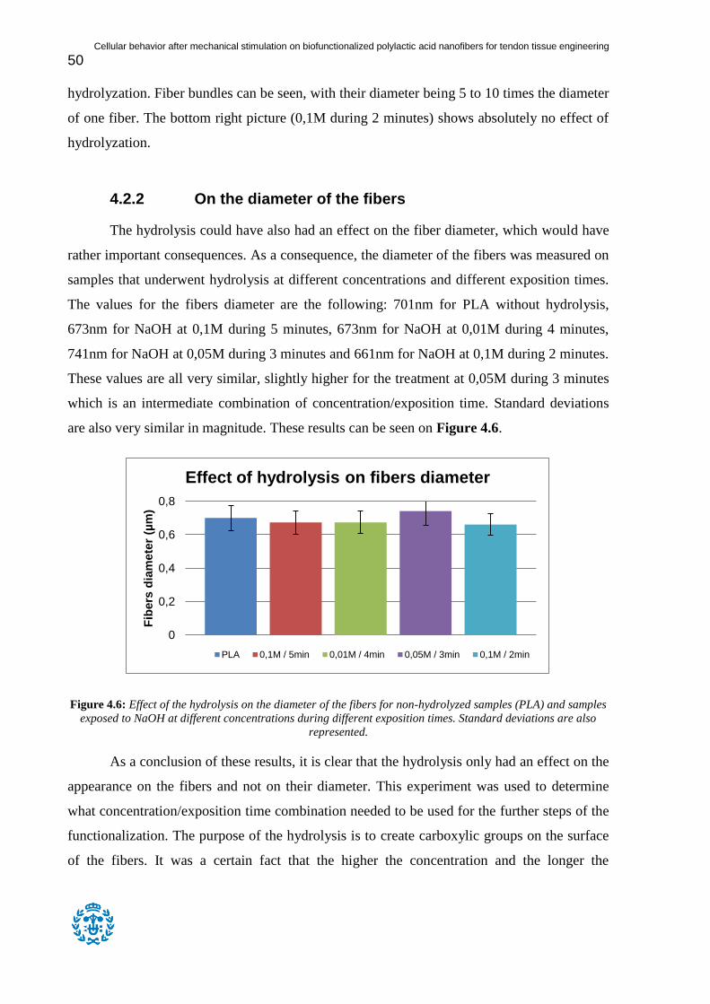
Cellular behavior after mechanical stimulation on biofunctionalized polylactic acid nanofibers for tendon tissue engineering
50
hydrolyzation. Fiber bundles can be seen, with their diameter being 5 to 10 times the diameter
of one fiber. The bottom right picture (0,1M during 2 minutes) shows absolutely no effect of
hydrolyzation.
4.2.2 On the diameter of the fibers
The hydrolysis could have also had an effect on the fiber diameter, which would have
rather important consequences. As a consequence, the diameter of the fibers was measured on
samples that underwent hydrolysis at different concentrations and different exposition times.
The values for the fibers diameter are the following: 701nm for PLA without hydrolysis,
673nm for NaOH at 0,1M during 5 minutes, 673nm for NaOH at 0,01M during 4 minutes,
741nm for NaOH at 0,05M during 3 minutes and 661nm for NaOH at 0,1M during 2 minutes.
These values are all very similar, slightly higher for the treatment at 0,05M during 3 minutes
which is an intermediate combination of concentration/exposition time. Standard deviations
are also very similar in magnitude. These results can be seen on Figure 4.6.
Figure 4.6: Effect of the hydrolysis on the diameter of the fibers for non-hydrolyzed samples (PLA) and samples
exposed to NaOH at different concentrations during different exposition times. Standard deviations are also
represented.
As a conclusion of these results, it is clear that the hydrolysis only had an effect on the
appearance on the fibers and not on their diameter. This experiment was used to determine
what concentration/exposition time combination needed to be used for the further steps of the
functionalization. The purpose of the hydrolysis is to create carboxylic groups on the surface
of the fibers. It was a certain fact that the higher the concentration and the longer the
0
0,2
0,4
0,6
0,8
Fib
ers
dia
mete
r (µ
m)
Effect of hydrolysis on fibers diameter
PLA 0,1M / 5min 0,01M / 4min 0,05M / 3min 0,1M / 2min

Cellular behavior after mechanical stimulation on biofunctionalized polylactic acid nanofibers for tendon tissue engineering
51
exposition time, the more carboxylic groups were created. Thus it was chosen to continue the
functionalization using the highest concentration/exposition time combination (0,5M during 5
minutes). Although the effect on the appearance of the fibers was not negligible, the
hydrolysis had an actual effect with these parameters and many carboxylic were definitely
present on the surface of the fibers. The choice was mainly driven by this objective.
4.3 Collagen immunofluorescence
Collagen type I was marked via immunofluorescence to detect its presence after the
functionalization process (Figure 4.7). The control samples exhibited no fluorescence
(bottom picture). The samples containing collagen covalently attached to the fibers showed an
important fluorescence, proving the presence of collagen type I (top left picture). The samples
attesting for the physical adsorption of collagen exhibited moderate fluorescence, which
demonstrate the presence of lower quantities of collagen compared to the samples containing
covalently bonded collagen.
Figure 4.7: Immunofluorescence marking for collagen type I on PLA fibers. Top left: covalently attached
collagen with EDC/NHS. Top right: collagen attached by physical adsorption. Bottom: no primary antibody.
(Nikon Eclipse E600).

Cellular behavior after mechanical stimulation on biofunctionalized polylactic acid nanofibers for tendon tissue engineering
52
This experiment was intended to mark collagen functionalized on the fibers via
immunofluorescence. In this test, the first antibody (or primary antibody) is an anti-collagen
antibody and normally attaches to collagen. The second antibody (or fluorescent antibody) is
an anti-primary antibody and normally attaches to the primary antibody. However, it is
possible that the second antibody attaches directly to collagen or PLA which would give
wrong observations. To verify that this does not happen, control samples containing only the
second antibody were also studied. These control samples showed absolutely no fluorescence,
proving that it does not attach to collagen or to non-functionalized PLA without the presence
of the primary antibody. Concerning the samples containing both antibodies, they actually
exhibited fluorescence. The functionalized samples showed a much higher fluorescence than
the non-functionalized samples. This proves that high quantities of collagen are attached to
the functionalized fibers whereas physical adsorption does not enable a good attachment of
collagen. The shape of the fibers can be clearly seen in both cases.
4.4 Collagen concentration with micro BCA assa
The collagen concentration of functionalized samples (covalently attached collagen)
was measured using the micro BCA assay. The samples had an average surface of 0,92cm².
On these samples, the collagen concentration was measured as an average 18,15µg/mL.
Therefore the efficiency of the grafting of collagen on the fibers is 18,15%. The results can be
seen in Table 4.3.
Table 4.3: Collagen type I concentration of functionalized samples. The initial concentration of collagen that
was incorporated onto the samples was 100µg/mL.
Concentration (µg/mL) Surface (cm²)
Mean 18,15 0,92
±3,65 ±0,06
4.5 Mechanical properties of functionalized scaffolds
Typical stress-strain curves for non-functionalized at room temperature (results from
4.1.3) and functionalized samples at 37° were drawn on the same graph in order to compare
them (Figure 4.8). The overall shape of the curve is similar: the three regions, toe, elastic and
yield, can still be seen. However, the toe region is much longer for functionalized samples and

Cellular behavior after mechanical stimulation on biofunctionalized polylactic acid nanofibers for tendon tissue engineering
53
goes to strains of almost 7% whereas for the non-functionalized samples, it only goes to a
maximum of 2,5%. The slopes of the elastic region of the two curves are very close from each
other. This will result in very close elastic modulus also. Moreover, the yield region seems to
start at a much lower stress but at a quite higher strain in the case of functionalized samples.
Figure 4.8: Comparison of stress-strain curves for functionalized samples tested at 37° (red) and non-
functionalized samples tested at room temperature (blue).
Following the same procedure as explained in paragraph 4.1.3, the mechanical
properties of the samples were calculated for the functionalized samples tested at 37°C. The
elastic modulus of these samples was 8,8MPa in average whereas it was 9,1MPa. The yield
strength and the yield strain were respectively 54,5MPa and 10,85% for the functionalized
samples at 37°C whereas they were 73,6MPa and 9,7% for the non-functionalized samples.
As expected from the curve, the yield strength is higher for non-functionalized samples
although the yield strain is higher for functionalized samples at 37°C. A summary of the
properties of the functionalized samples tested at 37°C can be seen in Table 4.4.
Table 4.4: Mechanical properties of functionalized samples tested at 37°C compared with dry samples tested at
room temperature.
Elastic
modulus (MPa) Yield strength
(MPa) Yield strain
(%)
Functionalized scaffolds at 37°C
8,8 ±0,5 54,5 ±0,7 10,85 ±0,49
0
20
40
60
80
100
120
0 5 10 15 20 25 30 35 40
Str
ess (
MP
a)
Strain (%)
Stress-strain curves (non-functionalized and functionalized)

Cellular behavior after mechanical stimulation on biofunctionalized polylactic acid nanofibers for tendon tissue engineering
54
Dry scaffolds at room temperature
9,1 ±1,1 73,6 ±4,1 9,7 ±1,3
This experiment was meant to recreate the testing conditions of the mechanical
stimulation of the samples that will be performed. Some parameters of the mechanical
stimulation such as the stimulation strain will be eventually deduced from this experiment.
The functionalized samples were left dipped in PBS until testing and the testing was done at
37°C. Temperature and humidity typically have the same effect: they give more elasticity to
the samples. In this case, the yield strain was improved by these parameters and the elastic
modulus was unchanged. However, the yield strength suffered a major drop, from an average
73,6MPa to 54,5MPa. Indeed, this can be partly due to the temperature. It is also possible that
such a loss of property was caused by the effect of humidity on the polymer. Since PLA
degrades with water, it is possible that the chemical treatments and the liquid in which the
samples were dipped in degraded the polymer, causing a loss of mechanical properties. The
aspect of the degradation of PLA has not been studied in this project, although it might have a
non-negligible effect on the integrity of the samples.
The choice of the strain for the mechanical stimulation was done thanks to this study.
This strain must not damage or deform plastically the samples but must be high enough to be
sensed by the cells. As a consequence, the value of 8% was chosen in the elastic region of the
curve, a few percent under the average yield strain to prevent the statistical differences
between the samples (10,85%).
4.6 Live cell staining for cellular viability
A live cell staining was performed to verify the ability of the scaffolds to support
cellular attachment. Images were taken with a fluorescence microscope (Figure 4.9). Cells
were clearly visible on the samples and adopted different shapes. Some cells still had a
rounded shape, although others showed a more elongated shape. The elongated cells all
pointed toward a unique direction. Moreover, the surface being fibers, it was not possible to
focus on many cells at the same time since the cells lie on different layers.

Cellular behavior after mechanical stimulation on biofunctionalized polylactic acid nanofibers for tendon tissue engineering
55
Figure 4.9: Live cell staining for rat MSC seeded on PLA fibrous scaffolds. (Nikon Eclipse E600)
The cells were only left few hours on the samples before the observation. However,
they seem to attach well to the samples. A decent density of cells can be seen as well as
elongated cells all pointing in one direction. It is very likely that this particular direction is the
direction of alignment of the fibers. This preliminary result is a very good indication that such
scaffolds can support cells and guide their behavior in the way it is designed to.
4.7 Cells immunofluorescence
Tenocytes were seeded on glass, functionalized PLA and non-functionalized PLA
samples and were observed via immunofluorescence after 1, 3 and 6 days of culture. The area
and the roundness of the cells were calculated using ImageJ.
The culture duration had no influence on the cells area for the functionalized PLA
samples. The values were very similar for all the time points with an average area between
1100µm² and 1200µm². Concerning PLA, the area of the cells was an average 874µm² on the
first day and increased then stabilized the next time points between 1100µm² and 1200µm².
The cells present on glass samples had an area of 2200µm² the first day, decreased on the
third day to 1784µm² and slightly increased the sixth day to 1894µm². These results can be
seen on Figure 4.10.

Cellular behavior after mechanical stimulation on biofunctionalized polylactic acid nanofibers for tendon tissue engineering
56
Figure 4.10: Cells area calculated for tenocytes seeded on glass, functionalized PLA and PLA during culture
periods of 1 day, 3 days and 6 days. The values were calculated using ImageJ.
On the first day, tenocytes seeded on PLA had a roundness of 0,333. The value
decreased and stabilized the next time points around 0,200. Concerning functionalized PLA,
the roundness was 0,256 for the first day, then decreased to 0,217 the third day and finally to
0,202 the sixth day. Cells seeded on glass samples had an average roundness of 0,522 the first
day, then decreased to 0,485 the third day and finally 0,326 the sixth day. These results can be
seen in Figure 4.11.
Figure 4.11: Cells roudness calculated for tenocytes seeded on glass, functionalized PLA and PLA during
culture periods of 1 day, 3 days and 6 days. The values were calculated using ImageJ.
0
500
1000
1500
2000
2500
Cells a
rea (
µm
²)
Cells area after culture Glass Functionalized
PLA PLA
day 1 day 3 day 6 day 1 day 3 day 6 day 1 day 3 day 6
0
0,1
0,2
0,3
0,4
0,5
0,6
0,7
0,8
0,9
1
Cells r
ou
dn
ess
Cells roundness after culture Glass Functionalized
PLA PLA
day 1 day 3 day 6 day 1 day 3 day 6 day 1 day 3 day 6

Cellular behavior after mechanical stimulation on biofunctionalized polylactic acid nanofibers for tendon tissue engineering
57
Figure 4.12: Fluorescence
images of tenocytes after 1
day of culture on different
materials.
Blue:cells nuclei (DAPI)
Red: cytoskeletons
(phalloidin)
Top: glass
Middle: functionalized PLA
Bottom: PLA
(Nikon Eclipse E600)
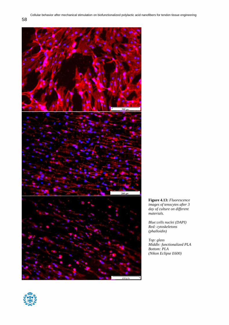
Cellular behavior after mechanical stimulation on biofunctionalized polylactic acid nanofibers for tendon tissue engineering
58
Figure 4.13: Fluorescence
images of tenocytes after 3
day of culture on different
materials.
Blue:cells nuclei (DAPI)
Red: cytoskeletons
(phalloidin)
Top: glass
Middle: functionalized PLA
Bottom: PLA
(Nikon Eclipse E600)

Cellular behavior after mechanical stimulation on biofunctionalized polylactic acid nanofibers for tendon tissue engineering
59
Figure 4.14: Fluorescence
images of tenocytes after 6
day of culture on different
materials.
Blue:cells nuclei (DAPI)
Red: cytoskeletons
(phalloidin)
Top: glass
Middle: functionalized PLA
Bottom: PLA
(Nikon Eclipse E600)

Cellular behavior after mechanical stimulation on biofunctionalized polylactic acid nanofibers for tendon tissue engineering
60
Figure 4.12, Figure 4.13 and Figure 4.14 represent tenocytes seeded on glass,
functionalized PLA and PLA after one, three and six days of culture respectively.
On glass after one day, the cells looked large and very slightly elongated without
showing any preferential orientation. On functionalized PLA, the cells looked much smaller
and very elongated in one unique direction. On PLA, the cells had a similar size and
elongation to the functionalized PLA cells and were also orientated in one direction, although
it was not as obvious as for functionalized PLA. Many cells could still be seen as very small
and round on PLA.
On glass after three days, the cells had approximately the same size and shape as for
the first day. On functionalized PLA, their shape and size also looked very similar to the first
day. They were still clearly elongated in one direction. On PLA, less small round cells could
be seen and the alignment direction was more obvious.
On glass after six days, the cells were more elongated than on the previous days.
However, they still did not show any orientation. On functionalized PLA, the cells still had a
similar shape, size and preferred orientation. Moreover, they were more densely packed than
on the previous days. On PLA, the observations were very similar to the one made on the
previous days.
This test is a good tool to observe the attachment of the tenocytes on these different
substrates. The area of a cell is typically considered as an effective parameter to indicate
whether the cells are well attached or not. In this case, the cells area was higher on glass,
which has a flat and homogeneous surface. However, the values were also quite promising for
the polymer fibers, showing that the tenocytes attached well to these substrates as well. On
functionalized PLA, the area of the cells was constant regardless of the culture duration. Cells
might have already reached an optimum attachment on the first day. For PLA, the area of the
cells was much lower on the first day but reached the same values as for functionalized PLA
on the third day. These results seem to show that the collagen present on functionalized PLA
offers to the cells a favorable surface to quickly attach, although after three days, the values
are similar for the two materials.

Cellular behavior after mechanical stimulation on biofunctionalized polylactic acid nanofibers for tendon tissue engineering
61
The roundness of the cells had also been calculated to describe the shape of the cells.
It was calculated with the following formula:
A roundness of 1 indicates a perfect circle, and the value decreases as the shape
changes. On glass, the roundness was relatively high on the first day and decreased after each
culture period (0,522 the first day, 0,485 the third day and 0,326 the sixth day). For both
functionalized PLA and PLA, the cells already had a low roundness on the first day, although
the value for PLA was higher than for the functionalized PLA at this time point. For both, the
value decreased on the third day and remained constant afterwards around 0,200. This value
might be close to the minimum roundness for tenocytes, which typically have a very
elongated shape. However, tests over longer periods should be done to confirm this
hypothesis. Just like the previous results showed, functionalized PLA presents a surface that
enables the cells to optimize their area and adopt a preferential shape in less than a day of
culture. Nevertheless, be it the area or the roundness, these two properties reach the same
value for functionalized PLA and PLA after three days of culture.
The observations made on the pictures are consistent with the values of area and
roundness that were calculated. However, one very important feature can be observed on
these pictures. In the case of functionalized PLA and PLA, which are composed of PLA
fibers, it is clearly visible that the cells align their shape along one unique direction. Whereas
cells seeded on glass do not show any preferential orientation. It is very likely that this
direction corresponds to the alignment direction of the fibers. Already on the first day, the
preferential alignment direction of the cells is very clear. Moreover, no matter what material
is considered, it is possible to see that the cells are more and more densely packed as days go
by. This could be a good indication that cellular proliferation is possible on such scaffolds.
However, proliferation tests should be carried to confirm this hypothesis since such
observations are purely qualitative. This whole experiment showed that functionalized PLA is
a good material to support cellular attachment and that its fibrous structure has a positive
effect on the cells. However, non-functionalized PLA shows similar results after three days of
culture. The influence of collagen on the surface should be further investigated.

Cellular behavior after mechanical stimulation on biofunctionalized polylactic acid nanofibers for tendon tissue engineering
62
4.8 Mechanical stimulation of seeded scaffolds
Due to experimental issues encountered during the test, the stimulation process had to
be stopped after one day and a half of stimulation process (8 hours of stimulation the first day
and 4 hours the second day for a total 12 hours of stimulation). The sample underwent a ramp
until 6mm at 0,1mm/s. The resulting stress-strain curve was similar to the curves obtained in
previous tests (Figure 4.15). A short toe region can be observed at very low strains, followed
by a linear elastic region and a yield region. The elastic modulus was calculated as the slope
of the elastic region and its value was 15,45MPa. The yield strength and the yield strain were
respectively calculated as 38,95MPa and 2,92%.
Figure 4.15: Stress-strain curve for PLA sample seeded with tenocytes stimulated during one day and a half
(total 12 hours of stimulation).
As it can be seen in Table 4.5, the material properties dramatically changed after the
stimulation: the material is stiffer but much more brittle. Compared to functionalized scaffolds
tested at 37°C, the elastic modulus increased by 75%, the yield strength decreased by 40%
and the yield strain was almost divided by 4. It was expected that tenocytes would produce
collagen, eventually leading to a stiffer material. However, such an important change of
1,09
7,39
13,69
19,99
26,29
32,59
38,89
45,19
51,49
57,79
0 4,04 8,08 12,12 16,16 20,2
Str
ess (
MP
a)
Strain (%)
Stress-strain curve for stimulated sample

Cellular behavior after mechanical stimulation on biofunctionalized polylactic acid nanofibers for tendon tissue engineering
63
elastic modulus and yield strain after a short period of stimulation is quite unlikely to be
explained only by the production of collagen.
An additional explanation could be the following. PLA is very sensitive to temperature
(its glass transition temperature is between 50°C and 55°C) and the presence of liquids. In this
case, the sample was dipped in culture medium at 37°C which are cell culture conditions and
these parameters are known to accelerate the physical ageing process of the polymer [41].
Physical ageing of a semi-crystalline or amorphous polymer can cause undesired
crystallization and thus making the material stiffer but more brittle. Buchatip et al. tested
different copolymers of L-lactide and DL-lactide having different crystallinities. Materials
with higher crystallinity proved to be stiffer and more brittle than amorphous copolymers in a
similar fashion as it was observed in this experiment. [25]
Table 4.5: Mechanical properties of a stimulated scaffold seeded with tenocytes tested at 37°C compared to
functionalized scaffolds tested at 37°C.
Elastic modulus
(MPa)
Yield strength
(MPa)
Yield strain
(%)
Stimulated scaffold at 37°C 15,45 38,95 2,92%
Functionalized scaffolds at
37°C 8,8 ±0,5 54,5 ±0,7 10,85 ±0,49
At the moment this report was finished, it had been impossible to make other
experiments. These observations should be taken into account for further experiments by
decreasing the stimulation strain for instance.

Cellular behavior after mechanical stimulation on biofunctionalized polylactic acid nanofibers for tendon tissue engineering
64

Cellular behavior after mechanical stimulation on biofunctionalized polylactic acid nanofibers for tendon tissue engineering
65
5 Conclusions
The objective of this project was to design and characterize aligned nanofibrous PLA
scaffolds functionalized with collagen type I and further seed tenocytes on the scaffolds to see
the influence of a mechanical stimulation on the scaffold and on the cells. All these efforts
were meant to create a scaffold and conditions that were as close as possible to tendons.
The electrospinning technique successfully produced aligned nano-scale fibers of
PLA. Their average diameter was determined as 700nm. Further, the mechanical properties of
the scaffolds were determined using the Bose Electroforce Biodynamic 5100. The scaffolds
showed to be viscoelastic with typical properties and behavior of fibrous mats.
The functionalization step was divided into two parts. The first part was the hydrolysis
of the scaffolds, which was meant to create carboxylic groups on the surface of the fibers. A
quick study was performed to select the best concentration of NaOH and the optimal
exposition time. In the next part, collagen type I was attached on the surface of the fibers
using carbodiimide chemistry. The couple EDC/NHS was used to create chemical bonds
between carboxylic groups created via hydrolysis and primary amino groups present on the
collagen molecule. A comparison was made between covalent bonding of collagen using
EDC/NHS and its physical adsorption on the surface of the fibers. Covalent bonding proved
to be the most efficient as it was expected.
Finally, tenocytes were seeded on functionalized and non-functionalized scaffolds as
well as glass. An immunofluorescence test was performed to observe the attachment of the
cells. While cells had a larger area on glass, they did not adopt an elongated shape. On both
non-functionalized and functionalized samples, cells had very elongated shapes and all
pointed toward a unique direction, the alignment direction of the fibers. This behavior is very
similar to what can be seen in natural tendons. No differences were noted in the area and the
shape of the cells after three days of culture while comparing functionalized and non-
functionalized samples.
The mechanical stimulation was not successful: the process had to be stopped after
one day and a half. The stimulated sample was mechanically tested and yielded surprising
results. Its elastic modulus increased by 75%, its yield strength decreased by 40% and its

Cellular behavior after mechanical stimulation on biofunctionalized polylactic acid nanofibers for tendon tissue engineering
66
yield strain was divided by 4. On such a short period, the collagen production of the fibers is
very unlikely to be responsible for these changes. Physical ageing was mentioned as a
probable cause of these modifications.
As a conclusion, aligned PLA nanofibers proved to be promising scaffolds for tendon
tissue engineering applications. Their size and mechanical properties resembled those of
natural tendons. The functionalization of the fibers with collagen was also successful although
its influence on the cells has not been clearly determined. Moreover, the aligned fibrous
structure of the scaffolds had a positive effect on the scaffolds as the cells adopted the same
elongated and unidirectional morphology. The process of mechanical stimulation is still not
functional and eventually led to incoherent results.

Cellular behavior after mechanical stimulation on biofunctionalized polylactic acid nanofibers for tendon tissue engineering
67
6 Future perspectives
Some additional experiments could be done to supplement the results presented in this
report. Most of the experiments presented in this part were not done mainly because of a lack
of time and in some cases experimental issues. Here are some suggestions.
The logical continuation of the project is to successfully stimulate the scaffolds seeded
with tenocytes and perform a cells immunofluorescence. Experimental issues made it
impossible to do on time. These tests should be done at the same time point as for the static
experiments in order to make the results comparable. Testing the mechanical properties of the
scaffolds at the end of the mechanical stimulation would give an idea of how much collagen is
produced by the cells and its influence on the mechanical properties. The collagen production
could also be seen via immunofluorescence or quantified with a micro BCA protein assay.
A proliferation assay such as the AlamarBlue assay could be performed on both the
dynamic and the static experiments to quantify the cellular proliferation on the scaffolds. The
observations made with the immunofluorescence pictures are entirely qualitative and would
need a quantitative measurement to be confirmed. The influence of collagen has not been
clearly identified in this report. However, the cellular proliferation could be affected by this
parameter.
Both the dynamic and the static experiments could be done over longer periods. In this
report, the experiments were done over 6 days and longer durations could reveal more
interesting observations.
The aspect of the degradation of PLA has not been considered in this project. However,
the degradation of PLA could lower the mechanical properties of the scaffolds which are
important properties in this project.

Cellular behavior after mechanical stimulation on biofunctionalized polylactic acid nanofibers for tendon tissue engineering
68
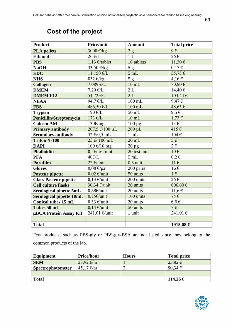
Cellular behavior after mechanical stimulation on biofunctionalized polylactic acid nanofibers for tendon tissue engineering
69
Cost of the project
Product Price/unit Amount Total price
PLA pellets 3000 €/kg 3 g 9 €
Ethanol 26 €/L 1 L 26 €
PBS 1,13 €/tablet 10 tablets 11,30 €
NaOH 33,50 €/kg 5 g 0,17 €
EDC 11.150 €/L 5 mL 55,75 €
NHS 832 €/kg 5 g 4,16 €
Collagen 7.089 €/L 10 mL 70,90 €
DMEM 7,20 €/L 2 L 14,40 €
DMEM F12 51,72 €/L 2 L 103,44 €
NEAA 94,7 €/L 100 mL 9,47 €
FBS 486,50 €/L 100 mL 48,65 €
Trypsin 190 €/L 50 mL 9,5 €
Penicillin/Streptomycin 173 €/L 10 mL 1,73 €
Calcein AM 130€/mg 100 µg 13 €
Primary antibody 207,5 €/100 µL 200 µL 415 €
Secondary antibody 52 €/0,5 mL 1 mL 104 €
Triton X-100 25 €/ 100 mL 20 mL 5 €
DAPI 100 €/10 mg 20 µg 2 €
Phalloidin 0,5€/test unit 20 test unit 10 €
PFA 40€/L 5 mL 0,2 €
Parafilm 22 €/unit 0,5 unit 11 €
Gloves 0,08 €/pair 200 pairs 16 €
Pasteur pipette 0,02 €/unit 50 units 1 €
Glass Pasteur pipette 0,13 €/unit 200 units 26 €
Cell culture flasks 30,34 €/unit 20 units 606,80 €
Serological pipette 5mL 0,58€/unit 20 units 11,6 €
Serological pipette 10mL 0,75€/unit 100 units 75 €
Conical tubes 15 mL 0,33 €/unit 20 units 6.6 €
Tubes 50 mL 0,14 €/unit 50 units 7 €
μBCA Protein Assay Kit 241,01 €/unit 1 unit 241,01 €
Total 1915,08 €
Few products, such as PBS-gly or PBS-gly-BSA are not listed since they belong to the
common products of the lab.
Equipment Price/hour Hours Total price
SEM 23,92 €/hr 1 23,92 €
Spectrophotometer 45,17 €/hr 2 90,34 €
Total 114,26 €

Cellular behavior after mechanical stimulation on biofunctionalized polylactic acid nanofibers for tendon tissue engineering
70
Only the equipment which requires a reservation and are paid at the hour is listed. Most of the
equipment used, such as the fluorescence microscope or the mechanical testing machine, is
free or belong to the research group.
Staff Price/hour Number of hours Total price
Senior researcher 30 €/hr 30 900 €
Lab technician 15 €/hr 50 750 €
Junior engineer 15 €/hr 600 9000 €
Total 10650 €
Estimated total cost of the project: 12679,94 €
Environmental impact
The material used in this project which is poly(lactic acid) is a biodegradable and
biocompatible polymer. Thus its degradation has no negative consequence on the
environment and only a small quantity of polymer was used to create the scaffolds.
Concerning the use of chemical and biological products, the laboratory has strict
norms concerning the disposal of such products. All the leftovers of chemical or biological
substances were poured in the appropriate recuperation containers, according to the
regulations. All the materials that had been in contact with chemical or biological substances
were thrown away in the appropriate trash bins.

Cellular behavior after mechanical stimulation on biofunctionalized polylactic acid nanofibers for tendon tissue engineering
71
7 References
[1] http://www.nsf.gov/od/lpa/nsf50/nsfoutreach/htm/n50_z2/pages_z3/45_pg.htm [Read:
30/12/2012]
[2] http://www.tissue-engineering.net/index.php?seite=whatiste [Read: 30/12/2012]
[3] http://www.physio.ie/injuries-and-conditions/rotator-cuff-injury/ (Read: 22/11/2012)
[4] V. Beachley, X. Wen
“Polymer nanofibrous structure: Fabrication, Biofunctionalization and cell interactions.”
Prog Polym Sci. 2012 July 1; 35(7): p868-892
[5] N. Juncosa-Melvin, G. P. Boivin, C. Gooch, M. T. Galloway, J. R. West, M. G. Dunn, D. L.
Butler
“The effect of Autologous Mesenchymal Stem Cells on the Biomechanics and Histology of
Gel-Collagen Sponge Constructs Used for Rabbit Patellar Tendon Repair.”
Tissue Engineering, Volume 12, Number 2, 2006: p369-379
[6] N. Juncosa-Melvin, G. P. Boivin, M. T. Galloway, C. Gooch, J. R. West, A. M. Sklenka, D. L.
Butler
“Effects of Cell-to-Collagen Ratio in Mesenchymal Stem Cell-Seeded Implants on Tendon
Repair Biomechanics and Histology.”
Tissue Engineering, Volume 11, Number 3/4, 2005: p448-457
[7] R. I. Abousleiman, Y. Reyes, P. McFetridge, V. Sikavitsas
“Tendon Tissue Engineering Using Cell-Seeded Umbilical Veins Cultured in a Mechanical
Stimulator”
Tissue Engineering, Part A, Volume 15, Number 4, 2009: p787-795
[8] V. S. Nirmalanandhan, N. Juncosa-Melvin, J. T. Shearn, G. P. Boivin, M. T. Galloway, C.
Gooch, G. Bradica, D. L. Butler
“Combined Effects of Scaffold Stiffening and Mechanical Preconditioning Cycles in Construct
Biomechanics, Gene Expression, and Tendon Repair Biomechanics.”
Tissue Engineering, Part A, Volume 15, Number 8, 2009: p2103-2111
[9] K. L. Moffat, A. S.-P. Kwei, J. P. Spalazzi, S. B. Doty, W. N. Levine, H. H. Lu
“Novel Nanofiber-Based Scaffold for Rotator Cuff Repair and Augmentation”

Cellular behavior after mechanical stimulation on biofunctionalized polylactic acid nanofibers for tendon tissue engineering
72
Tissue Engineering, Part A, Volume 26, Number 1, 2008: p115-126
[10] J. G. Barber, A. M. Handorf, T. J. Allee, W.-J. Li
“Braided Nanofibrous Scaffold for Tendon and Ligament Tissue Engineering”
Tissue Engineering, Part A, Volume 00, Number 00, 2011: p1-10
[11] D. C. Surrao, S. D. Waldman, B. G. Amsden
“Biomimetic poly(lactide) based fibrous scaffolds for ligament tissue engineering”
Acta Biomaterialia 8 (2012): p3997-4006
[12] http://www.engin.umich.edu/class/bme456/ligten/ligten.htm [Read: 21/11/2012]
[13] http://medim.sth.kth.se/neuronik/4E1150/downloads/F7_SoftTissue.pdf [Read: 21/11/2012]
[14] M. Kjær
“Role of Extracellular Matrix in Adaptation of Tendon and Skeletal Muscle to Mechanical
Loading”
Physiol. Rev, 84:p649-698
[15] G. Heness, B. Ben-Nissan
“Innovative Bioceramics”
Materials Forum, Vol. 27, 2004
[16] J. Czrenuszka
“Biomaterials under the microscope”
Materials World, Vol. 4, p452-453
[17] L. Avérous, E. Pollet
“Environmental Silicate Nano-Biocomposites”
Springer-Verlag, 2012, p13-39
[18] M. E. R. Coimbra, C. N. Elias and P. G. Coelho
“In vitro degradation of poly-l-d-lactic acid (PLDLA) pellets and powder used as synthetic
alloplasts for bone grafting”
J. of Materials Science: Materials in medicine. (2008)
[19] I. Vroman, L. Tighzert
“Biodegradable Polymers” (review)

Cellular behavior after mechanical stimulation on biofunctionalized polylactic acid nanofibers for tendon tissue engineering
73
Materials, 2, 2009, p307-344
[20] A. Jonquières
“Biopolymères et polymers biodegradables”
EEIGM (Nancy, France) course
[21] http://jimluntllc.com/pdfs/polylactic_fibers.pdf (Read: 09/01/2013)
[22] I. Kallela, R.-M. Tulamo, J. Hietanen, T. Pohjonen, R. Suuronen, C. Lindqvist
“Fixation of mandibular body osteotomies using biodegradable amorphous self-reinforced
(70L:30DL) polylactide or metal lag screws: an experimental study in sheep”
J. of Cranio-Maxillofacial Surgery (1999) 27, p124-133
[23] Vert, M., Schwacch, G. and Coudane, J.
J. Macromol. Sci. Pure, 1995, A32, 787
[24] Plastics Technology
January 1998, 13-15
[25] S. Buchatip, A. Petchsuk, K. Kongsuwan
“Synthesis and mechanical properties of poly(LLA-co-DLLA) copolymers”
[26] M. D. Edwards, G. R. Mitchell, S. D. Mohan, R. H. Olley
“Development of orientation during electrospinning of fibres of poly(ε-caprolactone)”
European Polymer Journal, Volume 46, Issue 6, June 2010, Pages 1175–1183 [27] Q. P. Pham, U. Sharma, A.G. Mikos
“Electrospinning of Polymeric Nanofibers for Tissue Engineering Applications: A Review”
Tissue Engineering Volume 12 Number 5, 2006, p1197-1211
[28] V. Beachley, X. Wen
“Effect of electrospinning parameters on the nanofibers diameter and length”
Materials Science and Engineering: C, 2009, p663–668
[29] Koski, A., Yim, K., and Shivkumar, S.
“Effect of molecular weight on fibrous PVA produced by electrospinning.”
Mater. Lett. 58, 493, 2004.
[30] H-T Hu, T-C Shin, S-Y Lee, C-C Chen, J-C Yang

Cellular behavior after mechanical stimulation on biofunctionalized polylactic acid nanofibers for tendon tissue engineering
74
“Influence of hydrolytic degradation on the surface properties of poly-5D/95L-lactide
resorbable bone plates”
Polymer Degradation and Stability, Volume 96, Issue 8, August 2011, p1522-1529
[31] http://www.piercenet.com/browse.cfm?fldID=CE4D6C5C-5946-4814-9904-
C46E01232683#carboxylate (Read: 07/01/2013)
[32] http://www.piercenet.com/browse.cfm?fldID=F3305493-0FBC-93DA-2720-4412D198A9C9
(Read: 07/01/2013)
[33] http://www.piercenet.com/browse.cfm?fldID=02040114 (Read: 07/01/2013)
[34] http://www.invitrogen.com/site/us/en/home/References/gibco-cell-culture-basics/cell-culture-
protocols/freezing-cells.html (Read: 09/01/2013)
[35] https://products.invitrogen.com/ivgn/product/12491015?ICID=search-product (Read:
09/01/2013)
[36] https://products.invitrogen.com/ivgn/product/25030024?ICID=search-product (Read:
09/01/2013)
[37] https://products.invitrogen.com/ivgn/product/15140122?ICID=search-15140122 (Read:
09/01/2013)
[38] https://products.invitrogen.com/ivgn/product/31331028?ICID=search-31331028 (Read:
09/01/2013)
[39] https://products.invitrogen.com/ivgn/product/11140035?ICID=search-11140035 (Read:
09/01/2013)
[40] A. Halder, M.E. Zobitz, F. Schultz, K.N. An
“Mechanical properties of the posterior rotator cuff”
Clinical Biomechanics 15 (2000) p456-462
[41] L. C. E. Struik
“Physical aging in plastics and other glassy materials.”