Ceiling Systems Technical Guide - Select Acoustic
32
This booklet provides drawings, details, and specification information for TechZone Ceiling Systems. TechZone is an integrated ceiling system that organizes the technical services that penetrate the ceiling into narrow linear technical “zones.” The zones organize lighting, air diffusers, air returns and sprinkler heads. Organizing these services results in a more monolithic, uncluttered ceiling visual that is created using standard components. Acoustical field panels can now be large size panels, free from penetrations. TECHZONE ™ Ceiling Systems Technical Guide Key Selection Attributes • Coordinated color finish with ceilings, suspension systems, light fixtures, air diffusers and air returns • Wide choice of field panel sizes to accommodate technical zone on-center spacing requirements • Standard ceiling and grid components used to create a custom look • Non-directional DuraBrite ® surface on ceiling panels for excellent durability and superior light reflectance • Outstanding acoustical performance • 30-year system performance guarantee against visible sag (HumiGuard ® Plus) and against mold/mildew and bacterial growth (Optima – inherent) (Ultima – BioBlock ® Plus) Applications Optima ® • Large ceiling areas • Open plan offices • Upscale retail settings • Airports • Media centers/libraries Ultima ® • Private offices • Conference rooms In this Booklet (also found on armstrong.com/techzone) Page 1 System layout and components Page 2 Technical panel options Page 4 Typical details • Perimeters • Partition attachment • Columns • Corridor transitions / System direction change Page 8 Configuration drawings and available sizes Page 28 Specifications Page 30 Design and installation considerations Between us, ideas become reality ™ CEILING SYSTEMS
Transcript of Ceiling Systems Technical Guide - Select Acoustic

This booklet provides drawings, deta i ls , and speci f icat ion informat ion for TechZoneCei l ing Systems.
TechZone is an integrated ceiling system that organizes the
technical services that penetrate the ceiling into narrow linear
technical “zones.” The zones organize lighting, air diffusers, air
returns and sprinkler heads. Organizing these services results in
a more monolithic, uncluttered ceiling visual that is created using
standard components. Acoustical field panels can now be large
size panels, free from penetrations.
TECHZONE ™
Cei l ing Systems
Techn ica l Gu ide
Key Select ion Attr ibutes
• Coordinated color finish with ceilings, suspensionsystems, light fixtures, air diffusers and air returns
• Wide choice of field panel sizes to accommodatetechnical zone on-center spacing requirements
• Standard ceiling and grid components used to create a custom look
• Non-directional DuraBrite® surface on ceiling panels forexcellent durability and superior light reflectance
• Outstanding acoustical performance
• 30-year system performance guarantee against visible sag (HumiGuard® Plus) and against mold/mildewand bacterial growth (Optima – inherent) (Ultima –BioBlock® Plus)
Appl icat ions
Optima®
• Large ceiling areas
• Open plan offices
• Upscale retail settings
• Airports
• Media centers/libraries
Ultima®
• Private offices
• Conference rooms
In th is Booklet (also found on armstrong.com/techzone)
Page 1 System layout and components
Page 2 Technical panel options
Page 4 Typical details• Perimeters• Partition attachment• Columns• Corridor transitions/
System direction change
Page 8 Configuration drawings and available sizes
Page 28 Specifications
Page 30 Design and installation considerations
B e t w e e n u s , i d e a s b e c o m e r e a l i t y ™
CEILING SYSTEMS

TechZone Optima®, Ultima® orMetal technical panel
Six-inch wide “technical zones” organize services, including lighting,air diffusers, air returns and sprinklers for a clean ceiling visual.
TechZone™ is a ceiling system using standard components:
• Lay-in and Tegular Optima® and Ultima® ceiling panels create the field.
• Lay-in and Tegular 6" wide technical panels in Optima, Ultimaor Metal form the “Technical Zone.” Metal technical panelsavailable in two perforation patterns, one for acoustics and onefor air return.
• Lay-in and Tegular recessed linear light fixtures, recesseddownlighting, pendants, air diffusers, air returns and sprinklersalign precisely in the “Technical Zone” for a clean linear visual.
• The entire system is prequalified for fit and finish.
TECHZONE PartnersArmstrong has teamed with industryleaders in lighting, air diffusers andsprinkler systems to create fixtures thatare prequalified for fit and finish in theTechZone Ceiling System. For moreinformation visit our web site atarmstrong.com/techzone
48" Cross Tee; 48" apart for panels
6" x 48" Recessed Light Fixture
6" x 48" Linear Diffuser
Flexible Sprinkler
Optima 48" x 48" Field Panel
48" Cross Tee; 6" apart for Technical Zone
Exposed Tee Main Beam(always runs perpendicular toTechnical Zones)
Section B
Tegular
0.250
6"
5"5.5"
Section B
9/16" Grid15/16" Grid
48" / 60"
47.5" / 59.5"47" / 59"
Section A
9/16" Grid15/16" Grid
Technical Zone Dimensions
1
S Y S T E M L A Y O U T A N D C O M P O N E N T S

2
Metal Lay-inTechnical Panel
Metal TegularTechnical Panel
6" 6"
48"/ 60" 48"/ 60"
Meta l Techn ica l Pane ls
9/16" Metal Lay-in Technical Panel 15/16" Metal Square Tegular Technical Panel
Cross SectionCross Section
Longitudinal SectionLongitudinal Section
Available Options:
• 9/16" or 15/16" Square Lay-in
• 9/16" or 15/16" Square Tegular
Perforation Options:
• Unperforated
• Microperforated (with acoustical fleece)
• Air Return Perforated (51% open)
Compatible Suspension Systems:
• Prelude® XL® 15/16" Exposed Tee System
• Suprafine® XL 9/16" Exposed Tee System
• Interlude® XL 9/16" Dimensional Tee System
• Silhouette® XL 9/16" Bolt-Slot System
T E C H N I C A L P A N E L O P T I O N S
INTERLUDE XL9/16"
Main Beam
PRELUDE XL15/16"
Main Beam
SUPRAFINE XL9/16"
Main Beam
SILHOUETTE XL9/16"
Main Beam with1/4" Reveal

6" 6"
3
Optima/Ultima TegularTechnical Panel
Optima/Ultima Lay-inTechnical Panel
48"/ 60" 48"/ 60"
Cross Section
Longitudinal SectionLongitudinal Section
9/16" or 15/16" Optima Lay-in Technical Panel 9/16" or 15/16" Optima Square Tegular Technical Panel
6" 6"
48"/ 60" 48"/ 60"
Cross SectionCross Section
Longitudinal SectionLongitudinal Section
9/16" or 15/16" Ultima Lay-in Technical Panel 9/16" or 15/16" Ultima Beveled Tegular Technical Panel
Available Options:
Optima
• 9/16" or 15/16" Square Lay-in
• 9/16" or 15/16" Square Tegular
Ultima
• 9/16" or 15/16" Square Lay-in
• 9/16" or 15/16" Beveled Tegular
Compatible Suspension Systems:
• Prelude® XL® 15/16" Exposed Tee System
• Suprafine® XL 9/16" Exposed Tee System
• Interlude® XL 9/16" Dimensional Tee System
• Silhouette® XL 9/16" Bolt-Slot System
Cross Section
Opt ima ® and U l t ima ® Technica l Pane ls
T E C H N I C A L P A N E L O P T I O N S
INTERLUDE XL9/16"
Main Beam
PRELUDE XL15/16"
Main Beam
SUPRAFINE XL9/16"
Main Beam
SILHOUETTE XL9/16"
Main Beam with1/4" Reveal

4
Per imeters
6" x 48" RecessedLight Fixture
Exposed TeeMain Beam
Drywall Cross Tee
Drywall Main Beam
Drywall Grid System
AXTBC
Hanger Wire
OPTIMA/ULTIMAField Panel
DDC or DLCC
DDC
GypsumBoard
5/8" GypsumBoard
Exposed Tee4' Cross Tee6" Apart for
Technical Zone
OPTIMA48" x 48" Field Panel
AXIOM ClassicPerimeter Trim
AXIOM ClassicPerimeter Trim
FlexibleSprinkler
TechZone OPTIMA, ULTIMA or Metal Technical Panel
Exposed TeeMain Beam
TechZone OPTIMA, ULTIMA or Metal Technical Panel
DWAC
ArmstrongExposed TeeGrid System
5/8" Gypsum BoardVaries
Exposed Tee4' Cross Tee6" Apart forTechnical Zone
4' Cross Tee 4' Apart for panels
TechZone OPTIMA,
ULTIMA or MetalTechnical Panel
TechZone OPTIMA, ULTIMAor Metal Technical Panel
#12 Hanger Wire
MBACChannelMolding
Exposed TeeMain Beam
Exposed TeeMain Beam
Exposed TeeMain Beam
AXIOM® Transition – Acoustical to Drywall
Drywall Surround with Acoustical Ceiling
T Y P I C A L D E T A I L S

5
Per imeters
Par t i t ion At tachment
Wall
Exposed Tee4' Cross Tee6" Apart for
Technical Zone
4' Cross Tee4' Apart for
panels
TechZone OPTIMA, ULTIMA or MetalTechnical Panel
PRELUDEMain Beam
PRELUDECross Tee
ChannelMolding
DW90C
Back Brace
DrywallGrid System
KAM-12KAM-12
Exposed TeeMain Beam
Exposed TeeMain Beam
Drywall Grid Soffit
Exposed TeeMain Beam
TechZone OPTIMA, ULTIMA or Metal Technical Panel
4' Cross Tee
OPTIMA48" x 48" Panel
Exposed Tee4' Cross Tee6" Apart forTechnical Zone
4' Cross Tee 4' Apart for panels
6" x 48" LinearDiffuser
TechZoneOPTIMA, ULTIMA or Metal Technical Panel
TechZoneOPTIMA or Metal
Technical Panel
Exposed TeeMain Beam
Top of partition wall
Universal partition clip
Exposed TeeMain Beam
FlexibleSprinkler
Exposed TeeMain Beam
Partition Wall
UPC
Exposed TeeMain Beam
TechZoneOPTIMA,ULTIMAor Metal
TechnicalPanel
Drywall Transition – Drywall to Acoustical Ceilings
T Y P I C A L D E T A I L S

6
Columns
Edge of Column Edge of Column
Angle MoldingCurved Around Column
Angle MoldingCurved Around
Column
OPTIMA/ULTIMA Tegular Field Panel
OPTIMA/ULTIMA Tegular Field Panel
TechZoneOPTIMA, ULTIMAor Metal Technical Panel
PRELUDEMain Beam
PRELUDEMain Beam
PRELUDECross Tee
PRELUDECross Tee
TechZone™ Around a Column Using Angle Molding
AX-V-TBC AX-V-TBC
OPTIMA or ULTIMA TegularField Panel
OPTIMA or ULTIMA TegularField Panel
2" AXIOM ClassicPerimeter Trim
2" AXIOM ClassicPerimeter Trim
AXIOM Min.Radius 2'
COLUMN
Main Beam Main Beam
Main BeamMain Beam
COLUMN
OPTIMA or ULTIMA TegularField Panel
OPTIMA or ULTIMA TegularField Panel
CurvedAngle Molding
Around Column
CurvedAngle MoldingAround Column
TechZone Around a Column Using AXIOM® Classic
TechZone Around a Column
7
T Y P I C A L D E T A I L S
Corr idor Trans i t ions/System Di rec t ion Change
OPTIMA TegularField Panel48" x 48"
OPTIMA TegularField Panel48" x 48"
OPTIMA TegularField Panel48" x 48"
OPTIMA TegularField Panel48" x 48"
OPTIMA TegularField Panel48" x 48"
OPTIMA TegularField Panel48" x 48"
OPTIMA TegularField Panel48" x 48"
OPTIMA TegularField Panel48" x 48"
OPTIMA TegularField Panel48" x 48"
OPTIMA TegularField Panel48" x 48"
OPTIMA TegularField Panel48" x 48"
OPTIMA TegularField Panel48" x 48"
OPTIMA TegularField Panel48" x 48"
OPTIMA TegularField Panel48" x 48"
OPTIMA TegularField Panel48" x 48"
TechZone OPTIMA, ULTIMA or Metal Technical Panel
TechZone OPTIMA, ULTIMA or Metal Technical Panel
TechZone OPTIMA, ULTIMA or Metal Technical Panel
AXIOM TransitionAXIOM Transition
EXPOSED TEEEXPOSED TEE
Hanger wire to structure within 8" of AXIOM
Hanger wire to structure within 8" of AXIOM
5/8" Gypsum BoardAXTBC AXTBC
Cross Tee
Main Beam
OPTIMA TegularField Panel
OPTIMA TegularField Panel
Cross Tee
Silhouette XL & Interlude XLEXPOSED TEE - Prelude XL & Suprafine XL
Main Beam
TechZone OPTIMA, ULTIMA or Metal Technical Panel
AXIOM TransitionTegular to Drywall
AXIOM TransitionTegular to Drywall

8
C O N F I G U R A T I O N D R A W I N G S & A V A I L A B L E S I Z E S
9/16" GRID
DESCRIPTION ITEM # ✔Field Panels
Optima 21" x 24" x 1" Sq. Tegular 3279
Technical Panels
Optima 6" x 48" x 1" Sq. Lay-in 1401
Optima 6" x 48" x 1" Sq. Tegular 1403
Ultima 6" x 48" x 3/4" Sq. Lay-in 1420
Ultima 6" x 48" x 3/4" Beveled Tegular 1423
Metal 6" x 48" x .025" Sq. Lay-in Unperforated 1652
Metal 6" x 48" x .025" Sq. Tegular Unperforated 1656
Metal 6" x 48" x .025" Sq. Lay-in Microperforated 1612
Metal 6" x 48" x .025" Sq. Lay-in Air Return Perforated 1642
Metal 6" x 48" x .025" Sq. Tegular Microperforated 1616
Metal 6" x 48" x .025" Sq. Tegular Air Return Perforated 1646
Grid Components
Suprafine XL 12' ID/HD Main Beam 7500/7501*
Suprafine XL 4' Cross Tee XL7540/7541**
Suprafine XL 21" Cross Tee XL7561
Interlude XL 12' HD Main Beam 6121
Interlude XL 4' Cross Tee XL6140
Interlude XL 21" Cross Tee XL6164
Silhouette XL 12' HD Main Beam 7611
Silhouette XL 4' Cross Tee - center notched one side XL7646
Silhouette XL 4' Cross Tee - center notched both sides XL7645
Silhouette XL 21" Cross Tee XL7621
21" x 24" Field Panels, 6" x 48" Technical Panels
MAIN
MAIN
21" CT 21" CT
4' C
T4'
CT
4' C
T
4' C
T4'
CT
COMPONENTS:Panels and Main Beams (Suprafine XL, Interlude XL, Silhouette XL)PANEL EF = 0.875MB EF = 0.25Cross Tees (Suprafine XL, Interlude XL)4' CT EF = 0.75 XL7540/7541; XL614021" CT EF = 0.219 XL7561; XL6161Cross Tees (Silhouette XL)4' CT EF = 0.25 XL76454' CT EF = 0.50 XL764621" CT EF = 0.219 XL7621
NOTE: Multiply ceiling area (SF) by the Estimating Factors (EF) todetermine lineal footage of grid components and square footage offield panels required.
Quantity of technical panels will be dependent on the type and quantityof fixtures and diffusers.
* Main Beam selected based on code/load requirement** Cross Tee selected based on code/load requirement
4 ' TechZone ™ Module
4'-0" On-Center Technical Zone Spacing
MAIN - 7611
XL7621 21" CT
XL7645Center Notched Both SidesXL7646Center Notched One Side

9
C O N F I G U R A T I O N D R A W I N G S & A V A I L A B L E S I Z E S
4' TechZone ™ Module
4'-0" On-Center Technical Zone Spacing
9/16" GRID
DESCRIPTION ITEM # ✔Field Panels
Optima 24" x 42" x 1" Sq. Tegular 3280
Technical Panels
Optima 6" x 48" x 1" Sq. Lay-in 1401
Optima 6" x 48" x 1" Sq. Tegular 1403
Ultima 6" x 48" x 3/4" Sq. Lay-in 1420
Ultima 6" x 48" x 3/4" Beveled Tegular 1423
Metal 6" x 48" x .025" Sq. Lay-in Unperforated 1652
Metal 6" x 48" x .025" Sq. Tegular Unperforated 1656
Metal 6" x 48" x .025" Sq. Lay-in Microperforated 1612
Metal 6" x 48" x .025" Sq. Lay-in Air Return Perforated 1642
Metal 6" x 48" x .025" Sq. Tegular Microperforated 1616
Metal 6" x 48" x .025" Sq. Tegular Air Return Perforated 1646
Grid Components
Suprafine XL 12' ID/HD Main Beam 7500/7501*
Suprafine XL 4' Cross Tee XL7540/7541**
Suprafine XL 42" Cross Tee XL7562
Interlude XL 12' ID/HD Main Beam 6100/6101A*
Interlude XL 4' Cross Tee XL6140
Interlude XL 42" Cross Tee XL6162
Silhouette XL 12' HD Main Beam 7609
Silhouette XL 4' Cross Tee - center notched one side XL7646
Silhouette XL 42" Cross Tee XL7642
24" x 42" Field Panels, 6" x 48" Technical Panels
MAIN
MAIN
42" CT
4' C
T4'
CT
4' C
T4'
CT
COMPONENTS:Panels and Main Beams (Suprafine XL, Interlude XL, Silhouette XL)PANEL EF = 0.876MB EF = 0.25Cross Tees (Suprafine XL, Interlude XL)4' CT EF = 0.50 XL7540/7541; XL614042" CT EF = 0.219 XL7562; XL6162Cross Tees (Silhouette XL)4' CT EF = 0.50 XL764642" CT EF = 0.219 XL7642
NOTE: Multiply ceiling area (SF) by the Estimating Factors (EF) todetermine lineal footage of grid components and square footage offield panels required.
Quantity of technical panels will be dependent on the type andquantity of fixtures and diffusers.
* Main Beam selected based on code/load requirement** Cross Tee selected based on code/load requirement
MAIN - 7609
XL7642UNNOTCHED
XL7646Center Notched One Side

10
4' TechZone ™ Module
4'-0" On-Center Technical Zone Spacing
9/16" GRID
DESCRIPTION ITEM # ✔Field Panels
Optima 42" x 48" x 1" Sq. Tegular 3267
Technical Panels
Optima 6" x 48" x 1" Sq. Lay-in 1401
Optima 6" x 48" x 1" Sq. Tegular 1403
Ultima 6" x 48" x 3/4" Sq. Lay-in 1420
Ultima 6" x 48" x 3/4" Beveled Tegular 1423
Metal 6" x 48" x .025" Sq. Lay-in Unperforated 1652
Metal 6" x 48" x .025" Sq. Tegular Unperforated 1656
Metal 6" x 48" x .025" Sq. Lay-in Microperforated 1612
Metal 6" x 48" x .025" Sq. Lay-in Air Return Perforated 1642
Metal 6" x 48" x .025" Sq. Tegular Microperforated 1616
Metal 6" x 48" x .025" Sq. Tegular Air Return Perforated 1646
Grid Components
Suprafine XL 12' ID/HD Main Beam 7500/7501*
Suprafine XL 4' Cross Tee XL7540/7541**
Interlude XL 12' ID/HD Main Beam 6100/6101A*
Interlude XL 4' Cross Tee XL6140
Silhouette XL 12' HD Main Beam 7609
Silhouette XL 4' Cross Tee XL7640
42" x 48" Field Panels, 6" x 48" Technical Panels
MAIN
4' C
T
MAIN
4' C
T
4' C
T4'
CT
COMPONENTS:Panels and Main Beams (Suprafine XL, Interlude XL, Silhouette XL)
PANEL EF = 0.875MB EF = 0.25Cross Tees (Suprafine XL, Interlude XL)4' CT EF = 0.50 XL7540/7541; XL6140Cross Tees (Silhouette XL)4' CT EF = 0.50 XL7640
NOTE: Multiply ceiling area (SF) by the Estimating Factors (EF) todetermine lineal footage of grid components and square footage offield panels required.
Quantity of technical panels will be dependent on the type andquantity of fixtures and diffusers.
* Main Beam selected based on code/load requirement** Cross Tee selected based on code/load requirement
MAIN - 7609
XL7640Unnotched

15/16" GRID 9/16" GRID
DESCRIPTION ITEM # ✔ DESCRIPTION ITEM # ✔Field Panels
Optima 48" x 48" x 1" Sq. Lay-in 3160 Optima 48" x 48" x 1" Sq. Tegular 3256
Optima 48" x 48" x 1" Sq. Tegular 3255
Technical Panels
Optima 6" x 48" x 1" Sq. Lay-in 1400 Optima 6" x 48" x 1" Sq. Lay-in 1401
Optima 6" x 48" x 1" Sq. Tegular 1402 Optima 6" x 48" x 1" Sq. Tegular 1403
Metal 6" x 48" x .025" Sq. Lay-in Unperforated 1650 Metal 6" x 48" x .025" Sq. Lay-in Unperforated 1652
Metal 6" x 48" x .025" Sq. Tegular Unperforated 1654 Metal 6" x 48" x .025" Sq. Tegular Unperforated 1656
Metal 6" x 48" x .025" Sq. Lay-in Microperforated 1610 Metal 6" x 48" x .025" Sq. Lay-in Microperforated 1612
Metal 6" x 48" x .025" Sq. Lay-in Air Return Perforated 1640 Metal 6" x 48" x .025" Sq. Lay-in Air Return Perforated 1642
Metal 6" x 48" x .025" Sq. Tegular Microperforated 1614 Metal 6" x 48" x .025" Sq. Tegular Microperforated 1616
Metal 6" x 48" x .025" Sq. Tegular Air Return Perforated 1644 Metal 6" x 48" x .025" Sq. Tegular Air Return Perforated 1646
Grid Components
Prelude XL 12' ID/HD Main Beam 7300/7301* Suprafine XL 12' ID/HD Main Beam 7500/7501*
Prelude XL 4' Cross Tee XL7340/7341** Suprafine XL 4' Cross Tee XL7540/7541 **
Prelude XL 4' Cross Tee XL7342/7348 Interlude XL 12' ID/HD Main Beam 6100/6101A*
Interlude XL 4' Cross Tee XL6140
Silhouette XL 9' HD Main Beam 7613
Silhouette XL 4' Cross Tee - center notched both sides XL7645
Silhouette XL 4' Cross Tee - center notched one side XL7646
Silhouette XL 2' Cross Tee XL7620
11
C O N F I G U R A T I O N D R A W I N G S & A V A I L A B L E S I Z E S
4' TechZone ™ Module
4'-6" On-Center Technical Zone Spacing
24" x 24" Field Panels, 6" x 48" Technical Panels
* Main Beam selected based on code/load requirement** Cross Tee selected based on code/load requirement
4' C
T 2' CT
4' C
T
4' C
T
4' C
T4'
CT2' CT
MAIN
MAIN
COMPONENTS:Panels and Main Beams (Prelude XL, Suprafine XL, Interlude XL,Silhouette XL)PANEL EF = 0.889MB EF = 0.25Cross Tees (Prelude XL, Suprafine XL, Interlude XL)4' CT EF = 0.666 XL7340/7341; XL7342/7348; XL7540/7541; XL61402' CT EF = 0.222 XL7328; XL7520; XL6120Cross Tees (Silhouette XL)4' CT EF = 0.222 XL76454' CT EF = 0.444 XL76462' CT EF = 0.222 XL7620
NOTE: Multiply ceiling area (SF) by the Estimating Factors (EF) todetermine lineal footage of grid components and square footage offield panels required.
Quantity of technical panels will be dependent on the type andquantity of fixtures and diffusers.
MAIN - 7613
XL7646Center Notched One Side
XL76202' CT
XL7645Center Notched Both Sides

12
15/16" GRID 9/16" GRID
DESCRIPTION ITEM # ✔ DESCRIPTION ITEM # ✔Field Panels
Optima 24" x 48" x 1" Sq. Lay-in 3153 Optima 24" x 48" x 1" Sq. Tegular 3257
Optima 24" x 48" x 1" Sq. Tegular 3252 Ultima 24" x 48" x 3/4" Bev. Tegular 1915
Ultima 24" x 48" x 3/4" Sq. Lay-in 1913
Ultima 24" x 48" x 3/4" Bev. Tegular 1914
Technical Panels
Optima 6" x 48" x 1" Sq. Lay-in 1400 Optima 6" x 48" x 1" Sq. Lay-in 1401
Optima 6" x 48" x 1" Sq. Tegular 1402 Optima 6" x 48" x 1" Sq. Tegular 1403
Ultima 6" x 48" x 3/4" Sq. Lay-in 1420 Ultima 6" x 48" x 3/4" Sq. Lay-in 1420
Ultima 24" x 48" x 3/4" Bev. Tegular 1422 Ultima 6" x 48" x 3/4" Bev. Tegular 1423
Metal 6" x 48" x .025" Sq. Lay-in Unperforated 1650 Metal 6" x 48" x .025" Sq. Lay-in Unperforated 1652
Metal 6" x 48" x .025" Sq. Tegular Unperforated 1654 Metal 6" x 48" x .025" Sq. Tegular Unperforated 1656
Metal 6" x 48" x .025" Sq. Lay-in Microperforated 1610 Metal 6" x 48" x .025" Sq. Lay-in Microperforated 1612
Metal 6" x 48" x .025" Sq. Lay-in Air Return Perforated 1640 Metal 6" x 48" x .025" Sq. Lay-in Air Return Perforated 1642
Metal 6" x 48" x .025" Sq. Tegular Microperforated 1614 Metal 6" x 48" x .025" Sq. Tegular Microperforated 1616
Metal 6" x 48" x .025" Sq. Tegular Air Return Perforated 1644 Metal 6" x 48" x .025" Sq. Tegular Air Return Perforated 1646
Grid Components
Prelude XL 12' ID/HD Main Beam 7300/7301* Suprafine XL 12' ID/HD Main Beam 7500/7501*
Prelude XL 4' Cross Tee XL7340/7341** Suprafine XL 4' Cross Tee XL7540/7541**
Prelude XL 4' Cross Tee XL7342/7348 Interlude XL 12' ID/HD Main Beam 6100/6101A*
Interlude XL 4' Cross Tee XL6140
Silhouette XL 9' HD Main Beam (installs w/panel long side parallel to technical zone)
Silhouette XL 9' HD Main Beam (installs w/panel long side perpendicular to technical zone)
Silhouette XL 4' Cross Tee XL7640
Silhouette XL 4' Cross Tee - center notched one side XL7646
Silhouette XL 2' Cross Tee XL7620
4 ' TechZone ™ Module
4'-6" On-Center Technical Zone Spacing
24" x 48" Field Panels, 6" x 48" Technical Panels
7613
7614
* Main Beam selected based on code/load requirement** Cross Tee selected based on code/load requirement
MAIN
A
4' C
T
4' C
T
4' C
T4'
CT4' CT
COMPONENTS:Panels and Main Beams (Prelude XL, Suprafine XL,Interlude XL, Silhouette XL)PANEL EF = 0.889MB EF = 0.25Cross Tees (Prelude XL, Suprafine XL, Interlude XL)4' CT EF = 0.666 XL7340/7341; XL7342/7348;
XL7540/7541; XL6140Cross Tees (Silhouette XL)A Configuration4' CT EF = 0.222 XL7640 4' CT EF = 0.444 XL7646 B Configuration4' CT EF = 0.666 XL7640
NOTE: Multiply ceiling area (SF) by the EstimatingFactors (EF) to determine lineal footage of gridcomponents and square footage of field panelsrequired.
Quantity of technical panels will be dependent on thetype and quantity of fixtures and diffusers.
B
MAIN
4' C
T4'
CT
4' C
T4'
CT
(or)
MAIN - 7614
XL7640UNNOTCHED
XL7646Center Notched One Side
A(or)
XL7640Unnotched
MAIN - 7613
B

13
C O N F I G U R A T I O N D R A W I N G S & A V A I L A B L E S I Z E S
15/16" GRID 9/16" GRID
DESCRIPTION ITEM # ✔ DESCRIPTION ITEM # ✔Field Panels
Optima 48" x 48" x 1" Sq. Lay-in 3160 Optima 48" x 48" x 1" Sq. Tegular 3256
Optima 48" x 48" x 1" Sq. Tegular 3255
Technical Panels
Optima 6" x 48" x 1" Sq. Lay-in 1400 Optima 6" x 48" x 1" Sq. Lay-in 1401
Optima 6" x 48" x 1" Sq. Tegular 1402 Optima 6" x 48" x 1" Sq. Tegular 1403
Metal 6" x 48" x .025" Sq. Lay-in Unperforated 1650 Metal 6" x 48" x .025" Sq. Lay-in Unperforated 1652
Metal 6" x 48" x .025" Sq. Tegular Unperforated 1654 Metal 6" x 48" x .025" Sq. Tegular Unperforated 1656
Metal 6" x 48" x .025" Sq. Lay-in Microperforated 1610 Metal 6" x 48" x .025" Sq. Lay-in Microperforated 1612
Metal 6" x 48" x .025" Sq. Lay-in Air Return Perforated 1640 Metal 6" x 48" x .025" Sq. Lay-in Air Return Perforated 1642
Metal 6" x 48" x .025" Sq. Tegular Microperforated 1614 Metal 6" x 48" x .025" Sq. Tegular Microperforated 1616
Metal 6" x 48" x .025" Sq. Tegular Air Return Perforated 1644 Metal 6" x 48" x .025" Sq. Tegular Air Return Perforated 1646
Grid Components
Prelude XL 12' ID/HD Main Beam 7300/7301* Suprafine XL 12' ID/HD Main Beam 7500/7501*
Prelude XL 4' Cross Tee XL7340/7341** Suprafine XL 4' Cross Tee XL7540/7541**
Prelude XL 4' Cross Tee XL7342/7348 Interlude XL 12' ID/HD Main Beam 6100/6101A*
Interlude XL 4' Cross Tee XL6140
Silhouette XL 9' HD Main Beam (installs w/panel long side perpendicular to technical zone)
Silhouette XL 4' Cross Tee XL7640
4 ' TechZone ™ Module
4'-6" On-Center Technical Zone Spacing
48" x 48" Field Panels, 6" x 48" Technical Panels
7614
* Main Beam selected based on code/load requirement** Cross Tee selected based on code/load requirement
4' C
T4'
CT
4' C
T4'
CT
MAIN
MAIN
COMPONENTS:Panels and Main Beams (Prelude XL, Suprafine XL, Interlude XL,Silhouette XL)PANEL EF = 0.889MB EF = 0.25Cross Tees (Prelude XL , Suprafine XL, Interlude XL)4' CT EF = 0.666 XL7340/7341; XL7342/7348; XL7540/7541;
XL6140Cross Tees (Silhouette XL )4' CT EF = 0.444 XL7640
NOTE: Multiply ceiling area (SF) by the Estimating Factors (EF) todetermine lineal footage of grid components and square footage offield panels required.
Quantity of technical panels will be dependent on the type andquantity of fixtures and diffusers.
MAIN - 7614
XL7640Unnotched

14
15/16" GRID 9/16" GRID
DESCRIPTION ITEM # ✔ DESCRIPTION ITEM # ✔Field Panels
Optima 24" x 24" x 1" Sq. Lay-in 3152 Optima 24" x 24" x 1" Sq. Tegular 3251
Optima 24" x 24" x 1" Sq. Tegular 3250 Ultima 24" x 24" x 3/4" Bev. Tegular 1912
Ultima 24" x 24" x 3/4" Sq. Lay-in 1910
Ultima 24" x 24" x 3/4" Bev. Tegular 1911
Technical Panels
Optima 6" x 48" x 1" Sq. Lay-in 1400 Optima 6" x 48" x 1" Sq. Lay-in 1401
Optima 6" x 48" x 1" Sq. Tegular 1402 Optima 6" x 48" x 1" Sq. Tegular 1403
Ultima 6" x 48" x 3/4" Sq. Lay-in 1420 Ultima 6" x 48" x 3/4" Sq. Lay-in 1420
Ultima 24" x 48" x 3/4" Bev. Tegular 1422 Ultima 6" x 48" x 3/4" Bev. Tegular 1423
Metal 6" x 48" x .025" Sq. Lay-in Unperforated 1650 Metal 6" x 48" x .025" Sq. Lay-in Unperforated 1652
Metal 6" x 48" x .025" Sq. Tegular Unperforated 1654 Metal 6" x 48" x .025" Sq. Tegular Unperforated 1656
Metal 6" x 48" x .025" Sq. Lay-in Microperforated 1610 Metal 6" x 48" x .025" Sq. Lay-in Microperforated 1612
Metal 6" x 48" x .025" Sq. Lay-in Air Return Perforated 1640 Metal 6" x 48" x .025" Sq. Lay-in Air Return Perforated 1642
Metal 6" x 48" x .025" Sq. Tegular Microperforated 1614 Metal 6" x 48" x .025" Sq. Tegular Microperforated 1616
Metal 6" x 48" x .025" Sq. Tegular Air Return Perforated 1644 Metal 6" x 48" x .025" Sq. Tegular Air Return Perforated 1646
Grid Components
Prelude XL 12' ID/HD Main Beam 7300/7301* Suprafine XL 12' ID/HD Main Beam 7500/7501*
Prelude XL 4' Cross Tee XL7340/7341** Suprafine XL 4' Cross Tee XL7540/7541**
Suprafine XL 2' Cross Tee XL7520
Interlude XL 12' ID/HD Main Beam 6100/6101A*
Interlude XL 4' Cross Tee XL6140
Interlude XL 2' Cross Tee XL6120
Silhouette XL 78" HD Main Beam 7616
Silhouette XL 4' Cross Tee - center notched one side XL7646
Silhouette XL 4' Cross Tee - center notched both sides XL7645
Silhouette XL 2' Cross Tee XL7620
4 ' TechZone ™ Module
6'-6" On-Center Technical Zone Spacing
24" x 24" Field Panels, 6" x 48" Technical Panels
* Main Beam selected based on code/load requirement** Cross Tee selected based on code/load requirement
COMPONENTS:Panels and Main Beams (Prelude XL, Suprafine XL, Interlude XL, Silhouette XL)PANEL EF = 0.938MB EF = 0.25Cross Tees (Prelude XL, Suprafine XL, Interlude XL)4' CT EF = 0.615 XL7340/7341; XL7540/7541; XL61402' CT EF = 0.231 XL7328; XL7520; XL6120Cross Tees (Silhouette XL)4' CT EF = 0.308 XL7645 4' CT EF = 0.308 XL7646 2' CT EF = 0.231 XL7620
NOTE: Multiply ceiling area (SF) by the Estimating Factors (EF) to determine linealfootage of grid components and square footage of field panels required.
Quantity of technical panels will be dependent on the type and quantity of fixtures and diffusers.
MAIN
MAIN
4' C
T
4' C
T
4' C
T4'
CT
4' C
T4'
CT
2' CT 2' CT 2' CT
MAIN - 7616
XL7646Center Notched One SideXL7620
XL7645Center NotchedBoth Sides

15
C O N F I G U R A T I O N D R A W I N G S & A V A I L A B L E S I Z E S
15/16" GRID 9/16" GRID
DESCRIPTION ITEM # ✔ DESCRIPTION ITEM # ✔Field Panels
Optima 24" x 72" x 1" Sq. Lay-in 3161 Optima 24" x 24" x 1" Sq. Tegular 3251
Optima 24" x 72" x 1" Sq. Tegular 3281 Optima 24" x 72" x 1" Sq. Tegular 3261
Technical Panels
Optima 6" x 48" x 1" Sq. Lay-in 1400 Optima 6" x 48" x 1" Sq. Lay-in 1401
Optima 6" x 48" x 1" Sq. Tegular 1402 Optima 6" x 48" x 1" Sq. Tegular 1403
Metal 6" x 48" x .025" Sq. Lay-in Unperforated 1650 Metal 6" x 48" x .025" Sq. Lay-in Unperforated 1652
Metal 6" x 48" x .025" Sq. Tegular Unperforated 1654 Metal 6" x 48" x .025" Sq. Tegular Unperforated 1656
Metal 6" x 48" x .025" Sq. Lay-in Microperforated 1610 Metal 6" x 48" x .025" Sq. Lay-in Microperforated 1612
Metal 6" x 48" x .025" Sq. Lay-in Air Return Perforated 1640 Metal 6" x 48" x .025" Sq. Lay-in Air Return Perforated 1642
Metal 6" x 48" x .025" Sq. Tegular Microperforated 1614 Metal 6" x 48" x .025" Sq. Tegular Microperforated 1616
Metal 6" x 48" x .025" Sq. Tegular Air Return Perforated 1644 Metal 6" x 48" x .025" Sq. Tegular Air Return Perforated 1646
Grid Components
Prelude XL 12' ID/HD Main Beam 7300/7301* Suprafine XL 12' ID/HD Main Beam 7500/7501*
Prelude XL 4' Cross Tee XL7340/7341** Suprafine XL 4' Cross Tee XL7540/7541**
Suprafine XL 2' Cross Tee XL7520
Interlude XL 12' ID/HD Main Beam 6100/6101A*
Interlude XL 4' Cross Tee XL6140
Interlude XL 2' Cross Tee XL6120
Silhouette XL 78" HD Main Beam 7619
Silhouette XL 6' Cross Tee XL7690
Silhouette XL 4' Cross Tee - center notched one side XL7646
4 ' TechZone ™ Module
6'-6" On-Center Technical Zone Spacing
24" x 72" Field Panels, 6" x 48" Technical Panels
* Main Beam selected based on code/load requirement** Cross Tee selected based on code/load requirement
6' CT
4' C
T
4' C
T4'
CT
4' C
T
MAIN
MAIN
COMPONENTS:Panels and Main Beams (Prelude XL, Suprafine XL, Interlude XL,Silhouette XL)PANEL EF = 0.923MB EF = 0.25Cross Tees (Prelude XL, Suprafine XL, Interlude XL)6' CT EF = 0.231 XL7390; XL7590; XL61904' CT EF = 0.308 XL7340/7341; XL7342/7348; XL7540/7541;
XL6120Cross Tees (Silhouette XL)6' CT EF = 0.231 XL7690 4' CT EF = 0.308 XL7646
NOTE: Multiply ceiling area (SF) by the Estimating Factors (EF) todetermine lineal footage of grid components and square footage offield panels required.
Quantity of technical panels will be dependent on the type andquantity of fixtures and diffusers.
MAIN - 7619
XL7646Center Notched One SideXL7690

16
4' TechZone ™ Module
7'-6" On-Center Technical Zone Spacing
9/16" GRID
DESCRIPTION ITEM # ✔Field Panels
Optima 42" x 48" x 1" Sq. Tegular 3287
Technical Panels
Optima 6" x 48" x 1" Sq. Lay-in 1401
Optima 6" x 48" x 1" Sq. Tegular 1403
Metal 6" x 48" x .025" Sq. Lay-in Unperforated 1652
Metal 6" x 48" x .025" Sq. Tegular Unperforated 1656
Metal 6" x 48" x .025" Sq. Lay-in Microperforated 1612
Metal 6" x 48" x .025" Sq. Lay-in Air Return Perforated 1642
Metal 6" x 48" x .025" Sq. Tegular Microperforated 1616
Metal 6" x 48" x .025" Sq. Tegular Air Return Perforated 1646
Grid Components
Suprafine XL 12' ID/HD Main Beam 7500/7501*
Suprafine XL 4' Cross Tee XL7540/7541**
Interlude XL 12' ID/HD Main Beam 6100/6101A*
Interlude XL 4' Cross Tee XL6140
Silhouette XL 11' HD Main Beam 7621
Silhouette XL 4' Cross Tee XL7640
42" x 48" Field Panels, 6" x 48" Technical Panels
* Main Beam selected based on code/load requirement** Cross Tee selected based on code/load requirement
COMPONENTS:Panels and Main Beams (Suprafine XL, Interlude XL, Silhouette XL)PANEL EF = 0.93MB EF = 0.25Cross Tees (Suprafine XL, Interlude XL)4' CT EF = 0.40 XL7540/7541; XL6140Cross Tees (Silhouette XL)4' CT EF = 0.40 XL7640
NOTE: Multiply ceiling area (SF) by the Estimating Factors (EF) todetermine lineal footage of grid components and square footage offield panels required.
Quantity of technical panels will be dependent on the type and quantityof fixtures and diffusers.
MAIN
MAIN
4' C
T4'
CT
4' C
T
4' C
T4'
CT
MAIN - 7621
XL7640Unnotched
XL7
640

17
C O N F I G U R A T I O N D R A W I N G S & A V A I L A B L E S I Z E S
4' TechZone ™ Module
8'-6" On-Center Technical Zone Spacing
15/16" GRID 9/16" GRID
DESCRIPTION ITEM # ✔ DESCRIPTION ITEM # ✔Field Panels
Optima 24" x 24" x 1" Sq. Lay-in 3152 Optima 24" x 24" x 1" Sq. Tegular 3251
Optima 24" x 24" x 1" Sq. Tegular 3250 Ultima 24" x 24" x 3/4" Bev. Tegular 1912
Ultima 24" x 24" x 3/4" Sq. Lay-in 1910
Ultima 24" x 24" x 3/4" Bev. Tegular 1911
Technical Panels
Optima 6" x 48" x 1" Sq. Lay-in 1400 Optima 6" x 48" x 1" Sq. Lay-in 1401
Optima 6" x 48" x 1" Sq. Tegular 1402 Optima 6" x 48" x 1" Sq. Tegular 1403
Ultima 6" x 48" x 3/4" Sq. Lay-in 1420 Ultima 6" x 48" x 3/4" Sq. Lay-in 1420
Ultima 24" x 48" x 3/4" Bev. Tegular 1422 Ultima 6" x 48" x 3/4" Bev. Tegular 1423
Metal 6" x 48" x .025" Sq. Lay-in Unperforated 1650 Metal 6" x 48" x .025" Sq. Lay-in Unperforated 1652
Metal 6" x 48" x .025" Sq. Tegular Unperforated 1654 Metal 6" x 48" x .025" Sq. Tegular Unperforated 1656
Metal 6" x 48" x .025" Sq. Lay-in Microperforated 1610 Metal 6" x 48" x .025" Sq. Lay-in Microperforated 1612
Metal 6" x 48" x .025" Sq. Lay-in Air Return Perforated 1640 Metal 6" x 48" x .025" Sq. Lay-in Air Return Perforated 1642
Metal 6" x 48" x .025" Sq. Tegular Microperforated 1614 Metal 6" x 48" x .025" Sq. Tegular Microperforated 1616
Metal 6" x 48" x .025" Sq. Tegular Air Return Perforated 1644 Metal 6" x 48" x .025" Sq. Tegular Air Return Perforated 1646
Grid Components
Prelude XL 12' ID/HD Main Beam 7300/7301* Suprafine XL 12' ID/HD Main Beam 7500/7501*
Prelude XL 4' Cross Tee XL7340/7341** Suprafine XL 4' Cross Tee XL7540/7541**
Prelude XL 4' Cross Tee XL7342/7348 Suprafine XL 2' Cross Tee XL7520
Interlude XL 12' ID/HD Main Beam 6100/6101A*
Interlude XL 4' Cross Tee XL6140
Interlude XL 2' Cross Tee XL6120
Silhouette XL 9' HD Main Beam 7622
Silhouette XL 4' Cross Tee - center notched one side XL7646
Silhouette XL 4' Cross Tee - center notched both sides XL7645
Silhouette XL 2' Cross Tee XL7620
24" x 24" Field Panels, 6" x 48" Technical Panels
* Main Beam selected based on code/load requirement** Cross Tee selected based on code/load requirement
COMPONENTS:Panels and Main Beams (Prelude XL, Suprafine XL,Interlude XL, Silhouette XL)PANEL EF = 0.941MB EF = 0.25Cross Tees (Prelude XL, Suprafine XL, Interlude XL)4' CT EF = 0.588 XL7340/7341; XL7342/7348;
XL7540/7541; XL61402' CT EF = 0.235 XL7328; XL7520; XL6120Cross Tees (Silhouette XL)4' CT EF = 0.235 XL76464' CT EF = 0.353 XL76452' CT EF = 0.235 XL7620
NOTE: Multiply ceiling area (SF) by the EstimatingFactors (EF) to determine lineal footage of gridcomponents and square footage of field panelsrequired.
Quantity of technical panels will be dependent on thetype and quantity of fixtures and diffusers.
4' C
T
4' C
T4'
CT
4' C
T
4' C
T
4' C
T4'
CT
2' CT 2' CT 2' CT 2' CT
MAIN
MAIN
MAIN - 7622XL7646Center Notched One Side
XL7645Center NotchedBoth Sides
XL7620
18
4' TechZone ™ Module
8'-6" On-Center Technical Zone Spacing
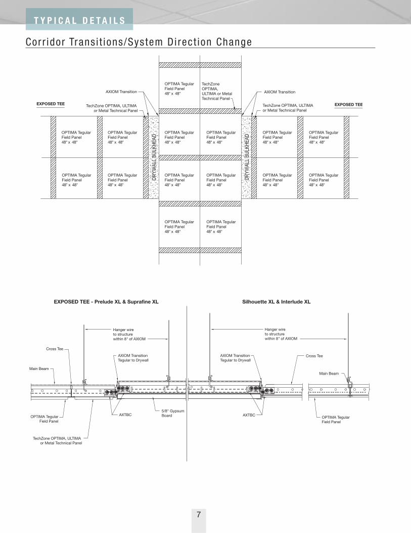
15/16" GRID 9/16" GRID
DESCRIPTION ITEM # ✔ DESCRIPTION ITEM # ✔Field Panels
Optima 24" x 96" x 3/4" Sq. Lay-in 3162 Optima 24" x 96" x 1" Sq. Tegular 3262
Optima 24" x 96" x 1" Sq. Tegular 3282
Technical Panels
Optima 6" x 48" x 1" Sq. Lay-in 1400 Optima 6" x 48" x 1" Sq. Lay-in 1401
Optima 6" x 48" x 1" Sq. Tegular 1402 Optima 6" x 48" x 1" Sq. Tegular 1403
Metal 6" x 48" x .025" Sq. Lay-in Unperforated 1650 Metal 6" x 48" x .025" Sq. Lay-in Unperforated 1652
Metal 6" x 48" x .025" Sq. Tegular Unperforated 1654 Metal 6" x 48" x .025" Sq. Tegular Unperforated 1656
Metal 6" x 48" x .025" Sq. Lay-in Microperforated 1610 Metal 6" x 48" x .025" Sq. Lay-in Microperforated 1612
Metal 6" x 48" x .025" Sq. Lay-in Air Return Perforated 1640 Metal 6" x 48" x .025" Sq. Lay-in Air Return Perforated 1642
Metal 6" x 48" x .025" Sq. Tegular Microperforated 1614 Metal 6" x 48" x .025" Sq. Tegular Microperforated 1616
Metal 6" x 48" x .025" Sq. Tegular Air Return Perforated 1644 Metal 6" x 48" x .025" Sq. Tegular Air Return Perforated 1646
Grid Components
Prelude XL 12' ID/HD Main Beam 7300/7301* Suprafine XL 12' ID/HD Main Beam 7500/7501*
Prelude XL 4' Cross Tee XL7340/7341** Suprafine XL 8' Cross Tee XL7580
Prelude XL 4' Cross Tee XL7342/7348 Suprafine XL 4' Cross Tee XL7540/7541**
Interlude XL 12' ID/HD Main Beam 6100/6101A*
Interlude XL 8' Cross Tee XL6180
Interlude XL 4' Cross Tee XL6140
Silhouette XL 102" HD Main Beam 7624
Silhouette XL 8' Cross Tee XL7680
Silhouette XL 4' Cross Tee - center notched one side XL7646
24" x 96" Field Panels, 6" x 48" Technical Panels
* Main Beam selected based on code/load requirement** Cross Tee selected based on code/load requirement
COMPONENTS:Panels and Main Beams (Prelude XL, Suprafine XL,Interlude XL, Silhouette XL)PANEL EF = 0.941MB EF = 0.25 Cross Tees (Prelude XL, Suprafine XL, Interlude XL)8' CT EF = 0.235 XL7380; XL7580; XL61804' CT EF = 0.235 XL 7340/7341; XL7342/7348;
XL7540/7541; XL6140Cross Tees (Silhouette XL)8' CT EF = 0.235 XL7680 4' CT EF = 0.235 XL7646
NOTE: Multiply ceiling area (SF) by the EstimatingFactors (EF) to determine lineal footage of gridcomponents and square footage of field panelsrequired.
Quantity of technical panels will be dependent on thetype and quantity of fixtures and diffusers.
MAIN
MAIN
8' CT
4' C
T4'
CT
4' C
T4'
CT
MAIN - 7624
XL7646Center Notched One SideXL7680
UNNOTCHED

19
C O N F I G U R A T I O N D R A W I N G S & A V A I L A B L E S I Z E S
4' TechZone ™ Module
8'-6" On-Center Technical Zone Spacing
15/16" GRID 9/16" GRID
DESCRIPTION ITEM # ✔ DESCRIPTION ITEM # ✔Field Panels
Optima 48" x 48" x 1" Sq. Lay-in 3160 Optima 48" x 48" x 1" Sq. Tegular 3256
Optima 48" x 48" x 1" Sq. Tegular 3255
Technical Panels
Optima 6" x 48" x 1" Sq. Lay-in 1400 Optima 6" x 48" x 1" Sq. Lay-in 1401
Optima 6" x 48" x 1" Sq. Tegular 1402 Optima 6" x 48" x 1" Sq. Tegular 1403
Metal 6" x 48" x .025" Sq. Lay-in Unperforated 1650 Metal 6" x 48" x .025" Sq. Lay-in 1652
Metal 6" x 48" x .025" Sq. Tegular Unperforated 1654 Metal 6" x 48" x .025" Sq. Tegular 1656
Metal 6" x 48" x .025" Sq. Lay-in Microperforated 1610 Metal 6" x 48" x .025" Sq. Lay-in Microperforated 1612
Metal 6" x 48" x .025" Sq. Lay-in Air Return Perforated 1640 Metal 6" x 48" x .025" Sq. Lay-in Air Return Perforated 1642
Metal 6" x 48" x .025" Sq. Tegular Microperforated 1614 Metal 6" x 48" x .025" Sq. Tegular Microperforated 1616
Metal 6" x 48" x .025" Sq. Tegular Air Return Perforated 1644 Metal 6" x 48" x .025" Sq. Tegular Air Return Perforated 1646
Grid Components
Prelude XL 12' ID/HD Main Beam 7300/7301* Suprafine XL 12' ID/HD Main Beam 7500/7501*
Prelude XL 4' Cross Tee XL7340/7341** Suprafine XL 4' Cross Tee XL7540/7541**
Prelude XL 4' Cross Tee XL7342/7348 Interlude XL 12' ID/HD Main Beam 6100/6101A*
Interlude XL 4' Cross Tee XL6140
Silhouette XL 102" HD Main Beam 7625
Silhouette XL 4' Cross Tee XL7640
48" x 48" Field Panels, 6" x 48" Technical Panels
* Main Beam selected based on code/load requirement** Cross Tee selected based on code/load requirement
COMPONENTS:Panels and Main Beams (Prelude XL, Suprafine XL,Interlude XL, Silhouette XL)PANEL EF = 0.941MB EF = 0.25 Cross Tees (Prelude XL, Suprafine XL, Interlude XL)4' CT EF = 0.353 7340/7341; 7342/7348;
7540/7541; 6140Cross Tees (Silhouette XL)4' CT EF = 0.353 XL7640
NOTE: Multiply ceiling area (SF) by the EstimatingFactors (EF) to determine lineal footage of gridcomponents and square footage of field panelsrequired.
Quantity of technical panels will be dependent on thetype and quantity of fixtures and diffusers.
4' C
T4'
CT
4' C
T
4' C
T4'
CT
MAIN
MAIN
MAIN - 7625
XL7640Unnotched
XL7
640

20
5' TechZone ™ Module
5'-0" On-Center Technical Zone Spacing
9/16" GRID
DESCRIPTION ITEM # ✔Field Panels
Optima 20" x 54" x 1" Sq. Tegular 3276
Technical Panels
Optima 6" x 60" x 1" Sq. Lay-in 1405
Optima 6" x 60" x 1" Sq. Tegular 1407
Metal 6" x 60" x .025" Sq. Lay-in Unperforated 1653
Metal 6" x 60" x .025" Sq. Tegular Unperforated 1657
Metal 6" x 60" x .025" Sq. Lay-in Microperforated 1613
Metal 6" x 60" x .025" Sq. Lay-in Air Return Perforated 1643
Metal 6" x 60" x .025" Sq. Tegular Microperforated 1617
Metal 6" x 60" x .025" Sq. Tegular Air Return Perforated 1647
Grid Components
Suprafine XL 12' ID/HD Main Beam 7500/7501*
Suprafine XL 5' Cross Tee XL7558
Suprafine XL 54" Cross Tee XL7564
Interlude XL 12' ID/HD Main Beam 6100/6101A*
Interlude XL 5' Cross Tee XL6152
Interlude XL 54" Cross Tee XL6162
Silhouette XL 10' HD Main Beam 7626
Silhouette XL 5' Cross Tee - notched one side at 20", 40" XL7651
Silhouette XL 54" Cross Tee XL7652
20" x 54" Field Panels, 6" x 60" Technical Panels
* Main Beam selected based on code/load requirement** Cross Tee selected based on code/load requirement
COMPONENTS:Panels and Main Beams (Suprafine XL, Interlude XL,Silhouette XL)PANEL EF = 0.90MB EF = 0.20 Cross Tees (Suprafine XL, Interlude XL)5' CT EF = 0.40 XL7558; XL615254" CT EF = 0.36 XL7564; XL6164Cross Tees (Silhouette XL)5' CT EF = 0.40 XL765154" CT EF= 0.36 XL7652
NOTE: Multiply ceiling area (SF) by the EstimatingFactors (EF) to determine lineal footage of gridcomponents and square footage of field panelsrequired.
Quantity of technical panels will be dependent on thetype and quantity of fixtures and diffusers.
MAIN
MAIN
54" CT
54" CT5' C
T5'
CT
5' C
T5'
CT
MAIN - 7626
XL7651Notched One Side@ 20", 40"
XL7652UNNOTCHED
9/16" GRID
DESCRIPTION ITEM # ✔Field Panels
Optima 27" x 30" x 1" Sq. Tegular 3283
Technical Panels
Optima 6" x 60" x 1" Sq. Lay-in 1405
Optima 6" x 60" x 1" Sq. Tegular 1407
Metal 6" x 60" x .025" Sq. Lay-in Unperforated 1653
Metal 6" x 60" x .025" Sq. Tegular Unperforated 1657
Metal 6" x 60" x .025" Sq. Lay-in Microperforated 1613
Metal 6" x 60" x .025" Sq. Lay-in Air Return Perforated 1643
Metal 6" x 60" x .025" Sq. Tegular Microperforated 1617
Metal 6" x 60" x .025" Sq. Tegular Air Return Perforated 1647
Grid Components
Suprafine XL 10' HD Main Beam 7504
Suprafine XL 5' Cross Tee XL7558
Suprafine XL 27" Cross Tee XL7567
Interlude XL 10' HD Main Beam 6127A
Interlude XL 5' Cross Tee XL6153
Interlude XL 27" Cross Tee XL6167
Silhouette XL 10' HD Main Beam 7627
Silhouette XL 5' Cross Tee - center notched both sides XL7655
Silhouette XL 5' Cross Tee - center notched one side XL7656
Silhouette XL 27" Cross Tee XL7652
21
C O N F I G U R A T I O N D R A W I N G S & A V A I L A B L E S I Z E S
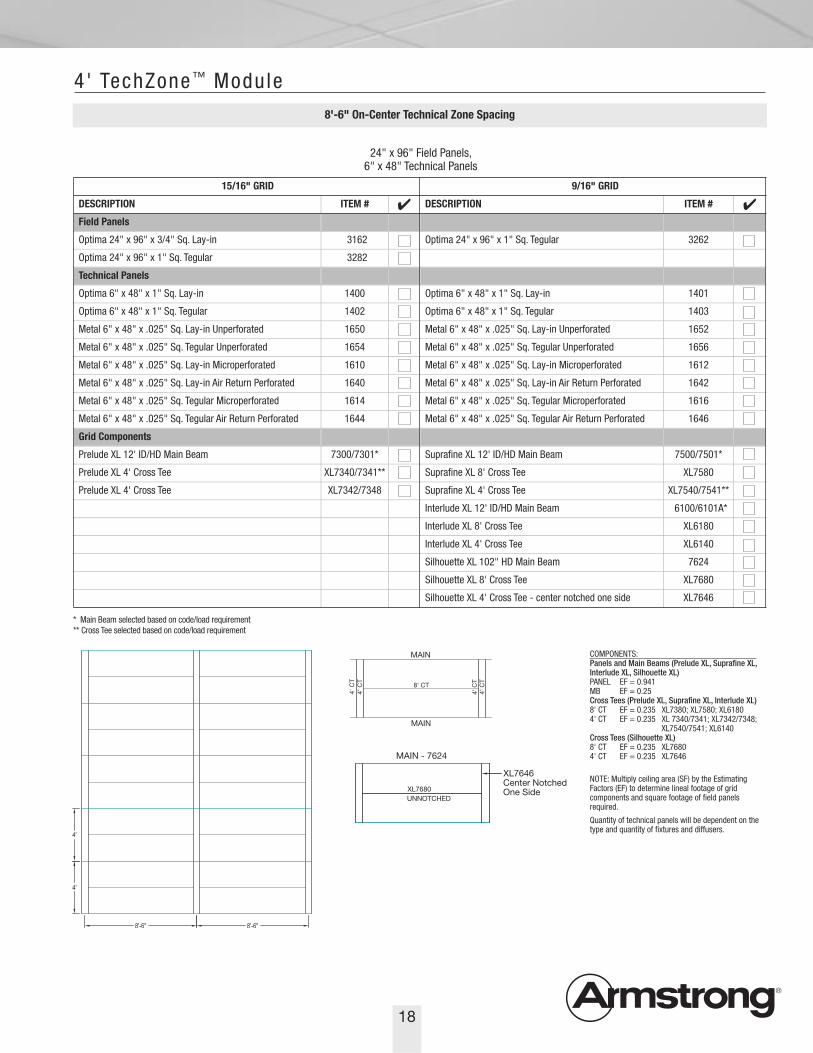
5' TechZone ™ Module
5'-0" On-Center Technical Zone Spacing
27" x 30" Field Panels, 6" x 60" Technical Panels
* Main Beam selected based on code/load requirement** Cross Tee selected based on code/load requirement
COMPONENTS:Panels and Main Beams (Suprafine XL, Interlude XL,Silhouette XL)PANEL EF = 0.90MB EF = 0.20 Cross Tees (Suprafine XL, Interlude XL)5' CT EF = 0.60 XL7558; XL615327" CT EF = 0.20 XL7567; XL6167Cross Tees (Silhouette XL)5' CT EF = 0.2 XL76555' CT EF = 0.4 XL765627" CT EF = 0.18 XL7627
NOTE: Multiply ceiling area (SF) by the EstimatingFactors (EF) to determine lineal footage of gridcomponents and square footage of field panelsrequired.
Quantity of technical panels will be dependent on thetype and quantity of fixtures and diffusers.
MAIN
MAIN
27" CT 27" CT
5' C
T5'
CT
5' C
T
5' C
T5'
CT
MAIN - 7627
XL7656Center Notched One SideXL7620
XL7655Center Notched Both Sides

22
9/16" GRID
DESCRIPTION ITEM # ✔Field Panels
Optima 30" x 54" x 1" Sq. Tegular 3284
Technical Panels
Optima 6" x 60" x 1" Sq. Lay-in 1405
Optima 6" x 60" x 1" Sq. Tegular 1407
Metal 6" x 60" x .025" Sq. Lay-in Unperforated 1653
Metal 6" x 60" x .025" Sq. Tegular Unperforated 1657
Metal 6" x 60" x .025" Sq. Lay-in Microperforated 1613
Metal 6" x 60" x .025" Sq. Lay-in Air Return Perforated 1643
Metal 6" x 60" x .025" Sq. Tegular Microperforated 1617
Metal 6" x 60" x .025" Sq. Tegular Air Return Perforated 1647
Grid Components
Suprafine XL 10' HD Main Beam 7504
Suprafine XL 10' ID Main Beam 7502
Suprafine XL 5' Cross Tee XL7558
Suprafine XL 54" Cross Tee XL7564
Interlude XL 12' ID/HD Main Beam 6100/6101A*
Interlude XL 5' Cross Tee XL6153
Silhouette XL 10' HD Main Beam 7626
Silhouette XL 5' Cross Tee - center notched one side XL7656
Silhouette XL 54" Cross Tee XL7652
30" x 54" Field Panels, 6" x 60" Technical Panels
* Main Beam selected based on code/load requirement** Cross Tee selected based on code/load requirement
COMPONENTS:Panels and Main Beams (Suprafine XL, Interlude XL,Silhouette XL)PANEL EF = 0.90MB EF = 0.20 Cross Tees (Suprafine XL, Interlude XL)5' CT EF = 0.40 XL7558; XL615354" CT EF = 0.18 XL7564; XL6164Cross Tees (Silhouette XL)5' CT EF = 0.40 XL765654" CT EF = 0.18 XL7652
NOTE: Multiply ceiling area (SF) by the EstimatingFactors (EF) to determine lineal footage of gridcomponents and square footage of field panelsrequired.
Quantity of technical panels will be dependent on thetype and quantity of fixtures and diffusers.
5' C
T5'
CT
5' C
T5'
CT 54" CT
MAIN
MAIN
5' TechZone ™ Module
5'-0" On-Center Technical Zone Spacing
MAIN - 7626
XL7656Center Notched One SideXL7652
UNNOTCHED

23
C O N F I G U R A T I O N D R A W I N G S & A V A I L A B L E S I Z E S
5' TechZone ™ Module
5'-6" On-Center Technical Zone Spacing
15/16" GRID 9/16" GRID
DESCRIPTION ITEM # ✔ DESCRIPTION ITEM # ✔Field Panels
Optima 20" x 60" x 1" Sq. Lay-in 3156 Optima 20" x 60" x 1" Sq. Tegular 3277
Optima 20" x 60" x 1" Sq. Tegular 3278
Technical Panels
Optima 6" x 60" x 1" Sq. Lay-in 1404 Optima 6" x 60" x 1" Sq. Lay-in 1405
Optima 6" x 60" x 1" Sq. Tegular 1406 Optima 6" x 60" x 1" Sq. Tegular 1407
Metal 6" x 60" x .025" Sq. Lay-in Unperforated 1651 Metal 6" x 60" x .025" Sq. Lay-in Unperforated 1653
Metal 6" x 60" x .025" Sq. Tegular Unperforated 1655 Metal 6" x 60" x .025" Sq. Tegular Unperforated 1657
Metal 6" x 60" x .025" Sq. Lay-in Microperforated 1611 Metal 6" x 60" x .025" Sq. Lay-in Microperforated 1613
Metal 6" x 60" x .025" Sq. Lay-in Air Return Perforated 1641 Metal 6" x 60" x .025" Sq. Lay-in Air Return Perforated 1643
Metal 6" x 60" x .025" Sq. Tegular Microperforated 1615 Metal 6" x 60" x .025" Sq. Tegular Microperforated 1617
Metal 6" x 60" x .025" Sq. Tegular Air Return Perforated 1645 Metal 6" x 60" x .025" Sq. Tegular Air Return Perforated 1647
Grid Components
A: Prelude XL 12' ID/HD Main Beam 7300/7301* A: Suprafine XL 12' ID/HD Main Beam 7500/7501*
B: Prelude XL 11' HD Main Beam 7306 B: Suprafine XL 11' HD Main Beam 7508
Prelude XL 5' Cross Tee XL7358 Suprafine XL 5' Cross Tee XL7558
A: Interlude XL 12' ID/HD Main Beam 6100/6101A*
B: Interlude XL 11' HD Main Beam 6132A
Interlude XL 5' Cross Tee XL6150
A: Silhouette XL 11' HD Main Beam (installs w/panel long side perpendicular to technical zone) 7629
B: Silhouette XL 11' HD Main Beam (installs w/panel long side parallel to technical zone) 7631
Silhouette XL 5' Cross Tee - notched one side at 20", 40" XL7651
Silhouette XL 5' Cross Tee XL7650
20" x 60" Field Panels, 6" x 60" Technical Panels
* Main Beam selected based on code/load requirement** Cross Tee selected based on code/load requirement
COMPONENTS:Panels and Main Beams (Prelude XL,Suprafine XL, Interlude XL, Silhouette XL)PANEL EF = 0.909MB EF = 0.20 Cross Tees (Prelude XL, Suprafine XL,Interlude XL)5' CT EF = 0.727 XL7358; XL7558;
XL6150Cross Tees (Silhouette XL)A Configuration:5' CT EF = 0.364 XL7651 5' CT EF = 0.364 XL7650 B Configuration5' CT EF = 0.727 XL7650
NOTE: Multiply ceiling area (SF) by theEstimating Factors (EF) to determine linealfootage of grid components and squarefootage of field panels required.
Quantity of technical panels will bedependent on the type and quantity offixtures and diffusers.
A
MAIN
5' CT
5' CT5' C
T5'
CT
5' C
T5'
CT
B
MAIN
5' C
T5'
CT
5' C
T
5' C
T
5' C
T5'
CT
MAIN - 7629
XL7651Notched One Side @ 20", 40"
XL7650UNNOTCHED
A
MAIN - 7631
XL7650Unnotched
XL7
650
B

24
5' TechZone ™ Module
5'-6" On-Center Technical Zone Spacing
15/16" GRID 9/16" GRID
DESCRIPTION ITEM # ✔ DESCRIPTION ITEM # ✔Field Panels
Optima 30" x 30" x 1" Sq. Lay-in 3158 Optima 30" x 30" x 1" Sq. Tegular 3259
Optima 30" x 30" x 1" Sq. Tegular 3258 Ultima 30" x 30" x 3/4" Bev. Tegular 1905
Technical Panels
Optima 6" x 60" x 1" Sq. Lay-in 1404 Optima 6" x 60" x 1" Sq. Lay-in 1405
Optima 6" x 60" x 1" Sq. Tegular 1406 Optima 6" x 60" x 1" Sq. Tegular 1407
Metal 6" x 60" x .025" Sq. Lay-in Unperforated 1651 Ultima 6" x 60" x 3/4" Sq. Lay-in 1425
Metal 6" x 60" x .025" Sq. Tegular Unperforated 1655 Ultima 6" x 60" x 3/4" Bev. Tegular 1427
Metal 6" x 60" x .025" Sq. Lay-in Microperforated 1611 Metal 6" x 60" x .025" Sq. Lay-in Unperforated 1653
Metal 6" x 60" x .025" Sq. Lay-in Air Return Perforated 1641 Metal 6" x 60" x .025" Sq. Tegular Unperforated 1657
Metal 6" x 60" x .025" Sq. Tegular Microperforated 1615 Metal 6" x 60" x .025" Sq. Lay-in Microperforated 1613
Metal 6" x 60" x .025" Sq. Tegular Air Return Perforated 1645 Metal 6" x 60" x .025" Sq. Lay-in Air Return Perforated 1643
Metal 6" x 60" x .025" Sq. Tegular Microperforated 1617
Metal 6" x 60" x .025" Sq. Tegular Air Return Perforated 1647
Grid Components
Prelude XL 12' ID/HD Main Beam 7300/7301* Suprafine XL 12' ID/HD Main Beam 7500/7501*
Prelude XL 5' Cross Tee XL7358* Suprafine XL 5' Cross Tee XL7558
Prelude XL 30" Cross Tee XL7378 Suprafine XL 30" Cross Tee XL7570
Interlude XL 12' ID/HD Main Beam 6100/6101A*
Interlude XL 5' Cross Tee XL6150
Interlude XL 30" Cross Tee XL6170
Silhouette XL 11' HD Main Beam 7635
Silhouette XL 5' Cross Tee - center notched both sides XL7655
Silhouette XL 5' Cross Tee - center notched one side XL7656
Silhouette XL 30" Cross Tee XL7670
30" x 30" Field Panels, 6" x 60" Technical Panels
* Main Beam selected based on code/load requirement** Cross Tee selected based on code/load requirement
COMPONENTS:Panels and Main Beams (Prelude XL, Suprafine XL,Interlude XL, Silhouette XL)PANEL EF = 0.909MB EF = 0.20 Cross Tees (Prelude XL, Suprafine XL, Interlude XL)5' CT EF = 0.545 XL7378; XL7558; XL615030" CT EF = 0.182 XL7570; XL6170Cross Tees (Silhouette XL)5' CT EF = 0.364 XL7656 5' CT EF = 0.182 XL765530" CT EF = 0.182 XL7670
NOTE: Multiply ceiling area (SF) by the EstimatingFactors (EF) to determine lineal footage of gridcomponents and square footage of field panelsrequired.
Quantity of technical panels will be dependent on thetype and quantity of fixtures and diffusers.
5' C
T
5' C
T5'
CT
5' C
T5'
CT
30" CT 30" CT
MAIN
MAIN
MAIN - 7635
XL7656Center Notched One SideXL7670
XL7655 Center Notched Both Sides
XL7670XL7656Center Notched One Side

25
C O N F I G U R A T I O N D R A W I N G S & A V A I L A B L E S I Z E S
5' TechZone ™ Module
5'-6" On-Center Technical Zone Spacing
15/16" GRID 9/16" GRID
DESCRIPTION ITEM # ✔ DESCRIPTION ITEM # ✔Field Panels
Optima 30" x 60" x 1" Sq. Lay-in 3157 Optima 30" x 60" x 1" Sq. Tegular 3285
Optima 30" x 60" x 1" Sq. Tegular 3286
Technical Panels
Optima 6" x 60" x 1" Sq. Lay-in 1404 Optima 6" x 60" x 1" Sq. Lay-in 1405
Optima 6" x 60" x 1" Sq. Tegular 1406 Optima 6" x 60" x 1" Sq. Tegular 1407
Metal 6" x 60" x .025" Sq. Lay-in Unperforated 1651 Metal 6" x 60" x .025" Sq. Lay-in Unperforated 1653
Metal 6" x 60" x .025" Sq. Tegular Unperforated 1655 Metal 6" x 60" x .025" Sq. Tegular Unperforated 1657
Metal 6" x 60" x .025" Sq. Lay-in Microperforated 1611 Metal 6" x 60" x .025" Sq. Lay-in Microperforated 1613
Metal 6" x 60" x .025" Sq. Lay-in Air Return Perforated 1641 Metal 6" x 60" x .025" Sq. Lay-in Air Return Perforated 1643
Metal 6" x 60" x .025" Sq. Tegular Microperforated 1615 Metal 6" x 60" x .025" Sq. Tegular Microperforated 1617
Metal 6" x 60" x .025" Sq. Tegular Air Return Perforated 1645 Metal 6" x 60" x .025" Sq. Tegular Air Return Perforated 1647
Grid Components
Prelude XL 12' ID/HD Main Beam 7300/7301* Suprafine XL 12' ID/HD Main Beam 7500/7501*
Prelude XL 11' HD Main Beam 7306 Suprafine XL 5' Cross Tee XL7558
Prelude XL 5' Cross Tee XL7358 Interlude XL 12' ID/HD Main Beam 6100/6101A*
Interlude XL 5' Cross Tee XL6150
A: Silhouette XL 11' HD Main Beam (installs w/panel long side perpendicular to technical zone) 7629
B: Silhouette XL 11' HD Main Beam (installs w/panel long side parallel to technical zone) 7635
Silhouette XL 5' Cross Tee - center notched one side XL7656
Silhouette XL 5' Cross Tee XL7650
30" x 60" Field Panels, 6" x 60" Technical Panels
* Main Beam selected based on code/load requirement** Cross Tee selected based on code/load requirement
COMPONENTS:Panels and Main Beams(Prelude XL, Suprafine XL,Interlude XL, Silhouette XL)PANEL EF = 0.909MB EF = 0.20 Cross Tees (Prelude XL,Suprafine XL, Interlude XL)5' CT EF = 0.545 XL7358;
XL7558;XL6150
Cross Tees (Silhouette XL)A Configuration5' CT EF = 0.364 XL7656 5' CT EF = 0.182 XL7650B Configuration5' CT EF = 0.545 XL7650
NOTE: Multiply ceiling area (SF)by the Estimating Factors (EF) todetermine lineal footage of gridcomponents and square footageof field panels required.
Quantity of technical panels willbe dependent on the type andquantity of fixtures and diffusers.
A
MAIN
5' CT
5' C
T5'
CT
5' C
T5'
CT
B
MAIN
5' C
T5'
CT
5' C
T5'
CT
5' C
T
MAIN - 7629
MAIN - 7629
XL7656Center Notched One SideXL7650
UNNOTCHED
A
MAIN - 7635
XL7650Unnotched
XL7
650
B

26
5' TechZone ™ Module
8'-0" On-Center Technical Zone Spacing
15/16" GRID 9/16" GRID
DESCRIPTION ITEM # ✔ DESCRIPTION ITEM # ✔Field Panels
Optima 30" x 30" x 1" Sq. Lay-in 3158 Optima 30" x 30" x 1" Sq. Tegular 3259
Optima 30" x 30" x 1" Sq. Tegular 3258 Ultima 30" x 30" x 3/4" Bev. Tegular 1905
Technical Panels
Optima 6" x 60" x 1" Sq. Lay-in 1404 Optima 6" x 60" x 1" Sq. Lay-in 1405
Optima 6" x 60" x 1" Sq. Tegular 1406 Optima 6" x 60" x 1" Sq. Tegular 1407
Metal 6" x 60" x .025" Sq. Lay-in Unperforated 1651 Ultima 6" x 60" x 3/4" Sq. Lay-in 1425
Metal 6" x 60" x .025" Sq. Tegular Unperforated 1655 Ultima 6" x 60" x 3/4" Bev. Tegular 1427
Metal 6" x 60" x .025" Sq. Lay-in Microperforated 1611 Metal 6" x 60" x .025" Sq. Lay-in Unperforated 1653
Metal 6" x 60" x .025" Sq. Lay-in Air Return Perforated 1641 Metal 6" x 60" x .025" Sq. Tegular Unperforated 1657
Metal 6" x 60" x .025" Sq. Tegular Microperforated 1615 Metal 6" x 60" x .025" Sq. Lay-in Microperforated 1613
Metal 6" x 60" x .025" Sq. Tegular Air Return Perforated 1645 Metal 6" x 60" x .025" Sq. Lay-in Air Return Perforated 1643
Metal 6" x 60" x .025" Sq. Tegular Microperforated 1617
Metal 6" x 60" x .025" Sq. Tegular Air Return Perforated 1647
Grid Components
Prelude XL 12' ID/HD Main Beam 7300/7301* Suprafine XL 12' ID/HD Main Beam 7500/7501*
Prelude XL 5' Cross Tee XL7358* Suprafine XL 5' Cross Tee XL7558
Prelude XL 30" Cross Tee XL7378 Suprafine XL 30" Cross Tee XL7570
Interlude XL 12' ID/HD Main Beam 6100/6101A*
Interlude XL 5' Cross Tee XL6150
Interlude XL 30" Cross Tee XL6170
Silhouette XL 8' HD Main Beam 7637
Silhouette XL 5' Cross Tee - center notched both sides XL7655
Silhouette XL 5' Cross Tee - center notched one side XL7656
Silhouette XL 30" Cross Tee XL7670
30" x 30" Field Panels, 6" x 60" Technical Panels
* Main Beam selected based on code/load requirement** Cross Tee selected based on code/load requirement
COMPONENTS:Panels and Main Beams (Prelude XL,Suprafine XL, Interlude XL, Silhouette XL)PANEL EF = 0.938MAINS EF = 0.20Cross Tees (Prelude XL, Suprafine XL,Interlude XL)5' CT EF = 0.57 XL7358; XL7558;
XL615030" CT EF = 0.188Cross Tees (Silhouette XL)5' CT EF = .025 XL7656 5' CT EF = .025 XL765530" CT EF = 0.188 XL7670
NOTE: Multiply ceiling area (SF) by theEstimating Factors (EF) to determine linealfootage of grid components and squarefootage of field panels required.
Quantity of technical panels will bedependent on the type and quantity of fixtures and diffusers.
5' C
T
MAIN
5' C
T
5' C
T5'
CT
5' C
T5'
CT
30" CT 30" CT 30" CT
MAIN
MAIN - 7637XL7656Notched One Side @ 30"
XL7655Center Notched Both Sides
XL7670 XL7656Center Notched One Side

10'-6" On-Center Technical Zone Spacing
27
C O N F I G U R A T I O N D R A W I N G S & A V A I L A B L E S I Z E S
5' TechZone ™ Module
15/16" GRID 9/16" GRID
DESCRIPTION ITEM # ✔ DESCRIPTION ITEM # ✔Field Panels
Optima 20" x 60" x 1" Sq. Lay-in 3156 Optima 20" x 60" x 1" Sq. Tegular 3277
Optima 20" x 60" x 1" Sq. Tegular 3278
Technical Panels
Optima 6" x 60" x 1" Sq. Lay-in 1404 Optima 6" x 60" x 1" Sq. Lay-in 1405
Optima 6" x 60" x 1" Sq. Tegular 1406 Optima 6" x 60" x 1" Sq. Tegular 1407
Metal 6" x 60" x .025" Sq. Lay-in Unperforated 1651 Metal 6" x 60" x .025" Sq. Lay-in Unperforated 1653
Metal 6" x 60" x .025" Sq. Tegular Unperforated 1655 Metal 6" x 60" x .025" Sq. Tegular Unperforated 1657
Grid Components
A: Prelude XL 12' ID/HD Main Beam 7300/7301* A: Suprafine XL 12' ID/HD Main Beam 7500/7501*
B: Prelude XL 11' HD Main Beam 7306 B: Suprafine XL 10' 6" HD Main Beam 7509
Prelude XL 5' Cross Tee XL7358 Suprafine XL 5' Cross Tee XL7558
A: Interlude XL 12' ID/HD Main Beam 6100/6101A*
B: Interlude XL 10' 6" HD Main Beam 6195
Interlude XL 5' Cross Tee XL6150
A: Silhouette XL 126" HD Main Beam (installs w/panel long side perpendicular to technical zone)
B: Silhouette XL 126" HD Main Beam(installs w/panel long side parallel to technical zone)
Silhouette XL 5' Cross Tee - notched both sides at 20", 40" XL7654
Silhouette XL 5' Cross Tee - notched one side at 20", 40" XL7651
Silhouette XL 5' Cross Tee - center notched one side XL7650
20" x 60" Field Panels, 6" x 60" Technical Panels
* Main Beam selected based on code/load requirement** Cross Tee selected based on code/load requirement
COMPONENTS:Panels and Main Beams (Prelude XL, Suprafine XL,Interlude XL, Silhouette XL)PANEL EF = 0.952MB EF = 0.2 Cross Tees (Prelude XL, Suprafine XL, Interlude XL)5' CT EF = 0.666 XL7358; XL7558; XL6150Cross Tees (Silhouette XL)5' CT EF = 0.19 XL7651 5' CT EF = 0.095 XL7653 5' CT EF = 0.381 XL7650 (A Configuration)5' CT EF = 0.666 XL7650 (B Configuration)
A
MAIN
5' CT
5' CT
5' CT
5' CT5' C
T5'
CT
5' C
T
5' C
T
B
MAIN
5 C
T
5' C
T5'
CT
5'C
T
5' C
T
5' C
T
5' C
T
5' C
T
5' C
T
7638
7639
MAIN - 7638
XL7651Notched One Side@ 20", 40"
XL7650
XL7654Notched Both Sides@ 20", 40"
A
NOTE: Multiply ceiling area (SF) by the EstimatingFactors (EF) to determine lineal footage of gridcomponents and square footage of field panels required.
Quantity of technical panels will be dependent on thetype and quantity of fixtures and diffusers.
MAIN - 7639
XL7650Center Notched One Side
XL7
650
B

28
S P E C I F I C A T I O N S
Armstrong World Industries, Inc.
Ceiling & Suspension System Specification
Please understand that you are responsible for the accuracy of all projectspecifications, including any Armstrong guide specifications that you use.
ARMSTRONG SHALL NOT BE LIABLE FOR ANY DAMAGES ARISING OUT OF THEUSE OF ANY OF ITS GUIDE SPECIFICATIONS.
Project Name: TechZone Ceiling Systems SECTION 09 58 00 (09545)INTEGRATED CEILING ASSEMBLIES
PART 1 – GENERAL
1.1 RELATED DOCUMENTS
Drawings and general conditions of Contract, including General andsupplementary Conditions and Divisions-1 Specification sections apply to work ofthis section.
1.2 SUMMARY
A. Section Includes:
1. Acoustical ceiling panels.
2. Exposed grid suspension system.
3. Wire hangers, fasteners, main runners, cross tees, and wall angle moldings.
B. Related Sections:
1. Section 09 20 00 (09250) - Plaster and Gypsum Board
2. Division 21 (13) Fire Suppression
3. Division 23 (15) - HVAC
4. Division 26 (16) Sections - Electrical Work
C. Alternates
1. Prior Approval: Unless otherwise provided for in the Contract documents,proposed product substitutions may be submitted no later than TEN (10)working days prior to the date established for receipt of bids. Acceptability of aproposed substitution is contingent upon the Architect’s review of theproposal for acceptability and approved products will be set forth by theAddenda. If included in a Bid are substitute products which have not beenapproved by Addenda, the specified products shall be provided withoutadditional compensation.
2. Submittals which do not provide adequate data for the product evaluation willnot be considered. The proposed substitution must meet all requirements ofthis section, including but not necessarily limited to, the following: Singlesource materials suppliers (if specified in Section 1.5); Underwriters’Laboratories Classified Acoustical performance; Panel design, size, composition, color, and finish; Suspension system component profiles andsizes; Compliance with the referenced standards.
1.3 REFERENCES
A. American Society for Testing and Materials (ASTM):
1. ASTM A1008 Standard Specification for Steel, Sheet, Cold Rolled, Carbon,Structural, High-Strength Low-Alloy and High-Strength Low-Alloy withImproved Formability.
2. ASTM A641 Standard Specification for Zinc-Coated (Galvanized) CarbonSteel Wire.
3. ASTM A653 Standard Specification for Steel Sheet, Zinc-Coated (Galvanized)by the Hot-Dip Process.
4. ASTM C423 Sound Absorption and Sound Absorption Coefficients by theReverberation Room Method.
5. ASTM C635 Standard Specification for Metal Suspension Systems forAcoustical Tile and Lay-in Panel Ceilings.
6. ASTM C636 Recommended Practice for Installation of Metal CeilingSuspension Systems for Acoustical Tile and Lay-in Panels.
7. ASTM E84 Standard Test Method for Surface Burning Characteristics ofBuilding Materials.
8. ASTM E1414 Standard Test Method for Airborne Sound Attenuation BetweenRooms Sharing a Common Ceiling Plenum.
9. ASTM E1111 Standard Test Method for Measuring the Interzone Attenuationof Ceilings Systems.
10. ASTM E1264 Classification for Acoustical Ceiling Products.
11. ASTM E1477 Standard Test Method for Luminous Reflectance Factor ofAcoustical Materials by Use of Integrating-Sphere Reflectometers.
12. ASTM D3273 Standard Test Method for Resistance to Growth of Mold on theSurface of Interior Coatings in an Environmental Chamber.
1.4 SUBMITTALS
A. Product Data: Submit manufacturer’s technical data for each type of acousticalceiling unit and suspension system required.
B. Samples: Minimum 6 inch x 6 inch samples of specified acoustical panel; 8 inchlong samples of exposed wall molding and suspension system, including mainrunner and 4 foot cross tees.
C. Shop Drawings: Layout and details of acoustical ceilings. Show locations ofitems which are to be coordinated with, or supported by the ceilings.
D. Prequalification: Compatibility of HVAC, lighting and sprinkler components thatare to be integrated into the system.
E. Certifications: Manufacturer’s certifications that products comply with specifiedrequirements, including laboratory reports showing compliance with specifiedtests and standards. For acoustical performance, each carton of material mustcarry an approved independent laboratory classification of NRC, CAC, and AC.
F. If the material supplied by the acoustical subcontractor does not have anUnderwriter’s Laboratory classification of acoustical performance on everycarton, subcontractor shall be required to send material from every productionrun appearing on the job to an independent or NVLAP approved laboratory fortesting, at the Architect’s or Owner’s discretion. All products not conforming tomanufacturer’s current published values must be removed, disposed of andreplaced with complying product at the expense of the Contractor performingthe work.
1.5 QUALITY ASSURANCE
A. Single-Source Responsibility: Provide acoustical panel units, technical panel units,and grid components by a single manufacturer.
B. Fire Performance Characteristics: Identify acoustical ceiling components withappropriate markings of applicable testing and inspecting organization.1. Surface Burning Characteristics: As follows, tested per ASTM E84 and
complying with ASTM E1264 for Class A products.a. Flame Spread: 25 or lessb. Smoke Developed: 50 or less
C. Handle acoustical ceiling units carefully to avoid chipping edges or damagedunits in any way.
1.6 DELIVERY, STORAGE, AND HANDLING
A. Deliver acoustical ceiling units to project site in original, unopened packagesand store them in a fully enclosed space where they will be protected againstdamage from moisture, direct sunlight, surface contamination, and othercauses.
B. Before installing acoustical ceiling units, permit them to reach roomtemperature and a stabilized moisture content.
C. Handle acoustical ceiling units carefully to avoid chipping edges or damagedunits in any way.
1.7 PROJECT CONDITIONS
A. Space Enclosure:
HumiGuard Plus Ceilings: Building areas to receive ceilings shall be free ofconstruction dust and debris. Products with HumiGuard Plus performance andhot dipped galvanized steel, aluminum, or stainless steel suspension systemscan be installed up to 120º F (49º C) and in spaces before the building is
enclosed, where HVAC systems are cycled or not operating. Cannot be used inexterior applications where standing water is present or where moisture willcome in direct contact with the ceiling.
1.8 WARRANTY
A. Acoustical Panel: Submit a written warranty executed by the manufacturer,agreeing to repair or replace acoustical panels that fail within the warranty period.Failures include, but are not limited to:
1. Acoustical Panels: Sagging and warping2. Grid System: Rusting and manufacturer’s defects
B. Warranty Period:
1. Optima®/Ultima® acoustical technical and field panels: Ten (10) years fromdate of substantial completion.
2. Grid: Ten (10) years from date of substantial completion.
3. Optima/Ultima acoustical field panels, unperforated metal or Optima/Ultimatechnical panels, and Armstrong grid systems is thirty (30) years from date ofsubstantial completion.
C. The Warranty shall not deprive the Owner of other rights the Owner may haveunder other provisions of the Contract Documents and will be in addition to andrun concurrent with other warranties made by the Contractor under therequirements of the Contract Documents.
1.9 MAINTENANCE
A. Extra Materials: Deliver extra materials to Owner. Furnish extra materialsdescribed below that match products installed. Packaged with protectivecovering for storage and identified with appropriate labels.
1. Acoustical Ceiling Units: Furnish quality of full-size units equal to 5.0 percentof amount installed.
2. Exposed Suspension System Components: Furnish quantity of each exposedsuspension component equal to 2.0 percent of amount installed.
Part 2 – PRODUCTS
2.1 MANUFACTURERS
A. TechZone™ Ceiling System:Armstrong World Industries, Inc.
2.2.0 ACOUSTICAL CEILING UNITS
A. Acoustical Panels Type ACT-1:
1. Surface Texture: Fine
2. Composition: (Optima Fiberglass, 1" thickness) (Ultima Mineral Fiber, 3/4"thickness)
3. Color: White
4. Sizes for fiberglass (Optima) field panels:
a. 4'0" Configurations (42 inches x 48 inches) (24 inches x 42 inches) (21 inches x 24 inches)
b. 4'6" Configurations [2 feet x (2) (4) (6) (8) feet] [4 feet x 4 feet]
c. 5'0" Configurations (27 inches x 30 inches) (30 inches x 54 inches) (20 inches x 54 inches)
d. 5'6" Configurations (30 inches x 30 inches) (30 inches x 60 inches) (20 inches x 60 inches)
e. 6'6" Configurations (24 inches x 24 inches) (24 inches x 72 inches)
f. 7'6" Configuration (42 inches x 48 inches)
g. 8'0" Configuration (30 inches x 30 inches)
h. 8'6" Configurations (24 inches x 24 inches) (24 inches x 96 inches) (48 inches x 48 inches)
i. 10'6" Congifuration (20 inches x 60 inches)
Sizes for mineral fiber (Ultima) field panels:
a. 4'6" Configurations [2 feet x (2) (4) feet]
b. 5'6" Configurations (30 inches x 30 inches)
c. 6'6" Configurations (24 inches x 24 inches)
d. 8'0" Configuration (30 inches x 30 inches)
e. 8'6" Configurations (24 inches x 24 inches)
5. Edge Profile: Square (Lay-In) (Tegular) for interface with (Prelude® XL®
15/16" Exposed Tee) (Suprafine® XL 9/16" Exposed Tee) (Interlude® XL9/16" Dimensional Tee) (Silhouette® XL 9/16" Bolt-Slot).
6. Noise Reduction Coefficient (NRC): ASTM C423; Classified with UL label onproduct carton,____.
7. Ceiling Attenuation Class (CAC): ASTM C1414; Classified with UL label onproduct carton, ____.
8. Articulation Class (AC) (Optima only): ASTM E1111; Classified with UL label onproduct carton, ____.
9. Flame Spread: ASTM E1264; Class A (UL)
10. Light Reflectance (LR): ASTM E1477; White Panel: Light Reflectance: 0.90.
11. Dimensional Stability: HumiGuard® Plus - temperatures up to 120 degrees Fand high humidity excluding only exterior use, use over standing water, anddirect contact with moisture.
12. Acceptable Product: (Optima Open Plan, Item #____) (Ultima, Item #_____), asmanufactured by Armstrong World Industries.
13. Application Consideration: For 4'0" and 5'0" Configurations only the 9/16"Systems (Suprafine XL, Interlude XL and Silhouette XL 9/16" Bolt-Slot) can beused.
B. TechZone Ceiling System
1. Technical Panels: The Technical Zone accommodates recessed fixtures,linear air diffusers, sprinkler heads, and other components.
a. Optima Technical Panels, 1" thickness
b. Ultima Technical Panels, 3/4" thickness
c. Metal Technical Panels - powder coated, galvanized steel, unperforated,microperforated, air return perforation
2. Size: (6 inch x 4 feet) (6 inch x 5 feet)
3. Color: White
4. Edge detail: Optima (Square Lay-in) (Square Tegular); Ultima (Square Lay-in)(Beveled Tegular); Metal (Square Lay-in) (Square Tegular)
5. Compatible grid systems: (Prelude XL 15/16" Exposed Tee) (Suprafine XL9/16" Exposed Tee) (Interlude XL 9/16" Dimensional Tee) (Silhouette XL 9/16"Bolt-Slot).
2.2.0 SUSPENSION SYSTEMS
A. Components: All main beams and cross tees shall be commercial quality hot-dipped galvanized steel as per ASTM A653. Main beams and cross tees aredouble-web steel construction with (9/16 inch) (15/16 inch) type exposedflange design. Exposed surfaces chemically cleansed, capping pre-finishedgalvanized steel in baked polyester paint. Main beams and cross tees shall haverotary stitching.
1. Structural Classification: ASTM C635, Intermediate Duty.
2. Color: White and match the actual color of the selected ceiling tile, unlessnoted otherwise.
3. Acceptable Product: (Prelude XL 15/16" Exposed Tee) (Silhouette XL 9/16"Bolt-Slot) (Suprafine XL 9/16" Exposed Tee) (Interlude XL Dimensional Tee) asmanufactured by Armstrong World Industries, Inc.
B. Attachment Devices: Size for five times design load indicated in ASTM C635,Table 1, Direct Hung unless otherwise indicated.
C. Wire for Hangers and Ties: ASTM A641, Class 1 zinc coating, soft temper, pre-stretched, with a yield stress load of at least three times design load, but notless than 12 gauge.
D. Edge Moldings and Trim: Metal or extruded aluminum of types and profilesindicated or, if not indicated, manufacturer’s standard moldings for edges andpenetrations, including light fixtures, that fit type of edge detail and suspensionsystem indicated. Provide moldings with exposed flange of the same width asexposed runner.
E. Accessories
29
S P E C I F I C A T I O N S
PART 3 – EXECUTION
3.1 EXAMINATION
A. Do not proceed with installation until all wet work such as concrete, terrazzo, plastering and painting has been completed and thoroughlydried out, unless expressly permitted by manufacturer’s printedrecommendations. (Exception: HumiGuard® Max Ceilings)
3.2 PREPARATION
A. Measure each ceiling area and establish layout of acoustical units to balanceborder widths at opposite edges of each ceiling. Avoid use of less than half widthunits at borders, and comply with reflected ceiling plans. Coordinate panellayout with mechanical and electrical fixtures.
B. Coordination: Furnish layouts for preset inserts, clips, and other ceiling anchorswhose installation is specified in other sections.
1. Furnish concrete inserts and similar devices to other trades for installationwell in advance of time needed for coordination of other work.
3.3 INSTALLATION
A. Install suspension system and panels in accordance with the manufacturer’sworking drawings, and in compliance with ASTM C636 and with the authoritieshaving jurisdiction.
B. Suspend main beam from overhead construction with hanger wires spaced 4-0on center along the length of the main runner. Install hanger wires plumb andstraight.
C. Install main beams perpendicular to the 6 inch wide Technical Panels.
D. Install wall moldings at intersection of suspended ceiling and vertical surfaces.Miter corners where wall moldings intersect or install corner caps.
E. For reveal edge panels: Cut and reveal or rabbet edges of ceiling panels at borderareas and vertical surfaces.
F. Install acoustical panels in coordination with suspended system, with edgesresting on flanges of main runner and cross tees. Cut and fit panels neatlyagainst abutting surfaces. Support edges by wall moldings.
3.4 ADJUSTING AND CLEANING
A. Replace damaged and broken panels.
B. Clean exposed surfaces of acoustical ceilings, including trim, edge moldings, andsuspension members. Comply with manufacturer’s instructions for cleaning andtouch-up of minor finish damage. Remove and replace work that cannot besuccessfully cleaned and repaired to permanently eliminate evidence of damage.
Design Considerations
• TechZone™ is especially appropriate for large expanses and open areasrequiring superior acoustics. The system with Optima® panels is notrecommended for closed offices and conference rooms where CACperformance is crucial; however, CAC backing is available upon request. Toprevent sound transmission in closed spaces, choose Ultima® field panels.Ultima mineral fiber ceilings have CAC 35 performance and the samecompatible DuraBrite® finish.
• Panels chosen for the technical zone may have an impact on overall acousticalperformance. Metal technical panels may or may not have a negative impact onspeech privacy, depending on the installation layout. For optimal acousticalperformance, choose Optima technical panels.
Installation Considerations
• TechZone ceiling systems are installed using standard 15/16" or 9/16" gridcomponents. The key difference is that main beams should be installedperpendicular to zones. Cross framing or Yoke suspension as detailed in CS-3479 (Armstrong Commercial Ceilings and Walls Solutions Guide) may berequired in instances where the building structure will not permit main beamsto be installed perpendicular to technical zones. This additional framing willimpact overall installed ceiling costs.
• Plenum depth required for the installation of panels is 3" for 2' x 4' panelsand 6" for 4' x 4' panels. In most cases installation of HVAC and can lightingwill require more plenum depth than the ceiling panels.
Other Considerations
• Optima and Ultima Lay-in field panels are not recommended with 9/16" grid.
• Interlude® XL® is not recommended when using lay-in technical panels.
Installation in Seismic Areas
There are no unique requirements for the installation of TechZone ceiling systemsin seismic areas. Consult your local code professional for information specific toyour region.
Perimeter Treatments and Transitions
Drawings available in the CS-3725 TechZone Technical Guide or visit our websiteat armstrong.com/techzone.
30

1 877 ARMSTRONG (276-7876)
TechLine – Technical information –
8 a.m. to 5:30 p.m. EST,
Monday through Friday
FAX 1-800-572-8324 or
email: [email protected]
armstrong.com/techzone
B e t w e e n u s , i d e a s b e c o m e r e a l i t y ™
CEILING SYSTEMS
TechLineSM / 1 877 ARMSTRONG1 877 276 7876
armstrong.com/ceilingsCS-3725-1009
All trademarks used herein are the property of AWI Licensing Company and/or its affiliates© 2009 AWI Licensing Company • Printed in the United States of America