cefns.nau.educefns.nau.edu/.../assets/engineering-analysis2.docx · Web viewDepartment of...
15
MSMA Lateral Loading Device By Matthew Batten, Cody Burbank, Thaddeus Grudniewski, Jonathan McCurdy, and Joy Weber Team 10 Engineering Analysis Document Submitted towards partial fulfillment of the requirements for Mechanical Engineering Design I – Fall 2013
Transcript of cefns.nau.educefns.nau.edu/.../assets/engineering-analysis2.docx · Web viewDepartment of...

MSMA Lateral Loading DeviceBy
Matthew Batten, Cody Burbank, Thaddeus Grudniewski,Jonathan McCurdy, and Joy Weber
Team 10
Engineering AnalysisDocument
Submitted towards partial fulfillment of the requirements forMechanical Engineering Design I – Fall 2013
Department of Mechanical EngineeringNorthern Arizona University
Flagstaff, AZ 86011

CONTENTS
1.0 Abstract………………………………………... 3
2.0 Background……………………………………. 3
3.0 Designs.……………………………………….. 4
4.0 Analysis………………………………………... 5
4.1 Towers…………………………………. 6
4.2 Base……………………………………. 7
4.3 Screws…………………………………. 8
5.0 Material Selection………………………………8
6.0 Conclusion……………………………………... 9
7.0 Citations……………………………………….. 9
8.0 Appendices …………………............................. 10
8.1 Appendix A: Gantt Chart……………… 10
8.2 Appendix B: By-Hand Calculations…… 11
2
1.0 ABSTRACT
This report will provide a brief background into the Magnetic Shape Memory Alloy (MSMA) Lateral Loading Device project. After reviewing the proposed design selections, the background for engineering analysis is provided, and the in depth analysis is covered. The analysis for this document was performed on two proposed mounting setups, one for an electromechanical actuator and one for a hydraulic actuator. In the end, the electromechanical actuator mounting setup was chosen for this design.
2.0 BACKROUND
At Northern Arizona University, Dr. Ciocanel is conducting research on MSMA’s. This material is fairly new and because of that, most of its mechanical properties are not known [3]. It is Dr. Ciocanel’s main goal is to discover these properties through testing. To conduct these tests, Dr. Ciocanel and his team of graduate students use an Instron machine. The Instron machine loads the selected material vertically, while applying a magnetic field horizontally, seen in Fig. 1 and Fig. 2. However, this experimental set up leaves an entire third dimension unexplored.
Figure 1: Close up of Instron machine Figure 2: Full Instron machine
Using basic analysis and decision matrices for the type of actuators and force sensors that could be implemented for the lateral loading two choices were chosen to be implemented. For force sensing a piezoelectric and transducer product were selected. For actuation electromechanical and piezoelectric stack designs were selected. The force sensor products,
3

Kistler 9313AA1 1-component force link [1] and Honeywell Model 11 Subminiature Tension/Compression Load Cell [5], are fairly similar in design. Both products are capable of handling the expected fatigue from testing, have similar sizes, and mounting setups. With this in mind, it was concluded that analysis would not need to be performed on these products. As for the actuators, the M-238 Heavy-Duty DC-Mike Actuator [4] and N-216 Nexline Linear Actuator [6], the forces exerted and experienced would be very similar. Therefore for the purpose of analysis the only differences would be in the dimensions of the mounting systems.
3.0 DESIGNS
Two different mounting designs were constructed, for the different actuator types. The unique geometries were than used in structural analysis to determine allowable materials and identify any problem areas. The mounting setup for the electromechanical product can be seen in Fig. 3.
Figure 3: Solidworks model of electromechanical mounting design
The design contains a semicircle base plate with towers attached on opposite sides by screws. The semicircle allows the system to be easily and accurately placed within the Instron. This allows for the ability to be removed or implemented for various tests. The tower on the right of the figure contains the back end mounting for the force sensor. The corner is cut to allow the tower to fit within the existing magnetic field structure. In the figure, two towers can be seen on the left of the MSMA. These towers hold the electromechanical actuator in place while
4

maintaining balance. The MSMA held by Material Testing Fixtures [2] is compressed by the add-ons of the actuator and force sensor. The mounting setup for the piezoelectric stack product can be seen in Fig. 4.
Figure 4: Solidworks model of piezoelectric stack mounting design
Similar to the electromechanical design this setup has a semicircle base with opposing towers. The sensor tower is set up exactly like in the electromechanical design, where the MSMA held by Material Testing Fixtures [2] is compressed by the add-ons of the actuator and force sensor. However, the actuator is held by a single, thicker tower. This is done because the piezoelectric stack actuator is a shorter length. With the given length there is no need to use two towers.
4.0 ANALYSIS
After creating the unique designs, the mounting was broken into sub-components for better analysis of the locations of failure. These sub-components are the tower holding the force sensor, the tower holding the actuator, the base, and the screws to assemble the parts.
4.1 TOWERS
5

For each of these towers a force of 200 N was applied to the area that would hold the actuation device. This force was calculated after a conversation with the client about the maximum amount of stress that will need to be applied to the MSMA to acquire the required results. The force sensing tower would be used in both designs but based on the selection of actuator (piezoelectric or electromechanical) the tower holding the actuators shape will vary. The results that were obtained using SolidWorks were corroborated by the by-hand analysis depicted in appendix B. Based upon these results the forces were found to be minimal compared with the expected strengths of most metals for all actuator towers.
Figure 5: Force Sensing Tower Analysis Figure 6: Electromechanical Tower 1 Analysis
6

Figure 7: Electromechanical Tower 2 Analysis Figure 8: Piezoelectric Tower Analysis
4.2 BASE
The base is attached to the towers using screws. It was here that our system was analyzed to see if the forces applied by the screws on the base would cause significant deformation or failure in the base. Fig. 9 shows an exaggerated deformation for the base design. The results show that the forces are fairly minimal in this case and that most commercially available materials would work for this application.
7

Figure 9: Base Analysis
4.3 SCREWS
The analysis of the screws involved a manual calculation of the shear stresses caused by the force exerted by the actuator on the tower. The force is transmitted to the sides of each tap used to fix the tower to the base. The stress calculations use the full force divided by the projected area of each hole. The resulting stress should be divided by the chosen amount of screws. The calculations are presented in Appendix B.
5.0 MATERIAL SELECTION
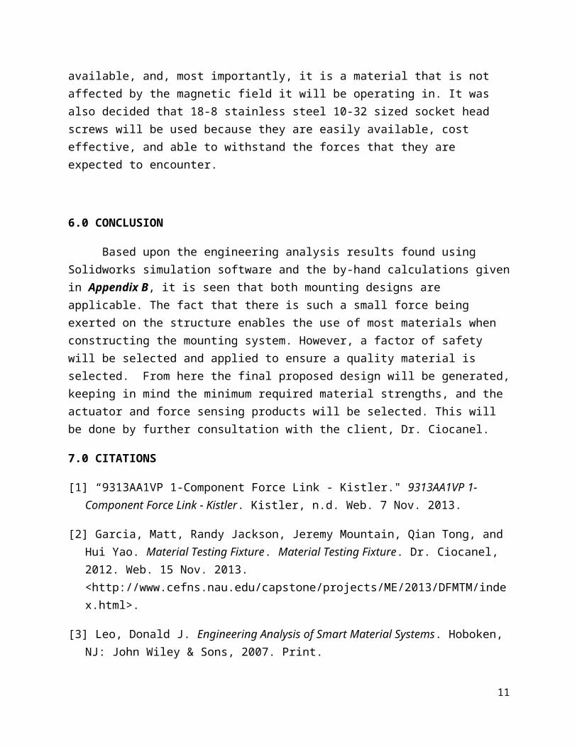
Through the analysis that was detailed in the previous section it could be determined that the stresses on most of these parts will be minimal, allowing for us to use the initial structural choice of 6061 aluminum alloy. This material is ideal for the construction of the frame because it is fairly lightweight allowing for portability, not too expensive, widely available, and, most importantly, it is a material that is not affected by the magnetic field it will be operating in. It was also decided that 18-8 stainless steel 10-32 sized socket head screws will be used because they are easily available, cost effective, and able to withstand the forces that they are expected to encounter.
8

6.0 CONCLUSION
Based upon the engineering analysis results found using Solidworks simulation software and the by-hand calculations given in Appendix B, it is seen that both mounting designs are applicable. The fact that there is such a small force being exerted on the structure enables the use of most materials when constructing the mounting system. However, a factor of safety will be selected and applied to ensure a quality material is selected. From here the final proposed design will be generated, keeping in mind the minimum required material strengths, and the actuator and force sensing products will be selected. This will be done by further consultation with the client, Dr. Ciocanel.
7.0 CITATIONS
[1] “9313AA1VP 1-Component Force Link - Kistler." 9313AA1VP 1-Component Force Link - Kistler. Kistler, n.d. Web. 7 Nov. 2013.
[2] Garcia, Matt, Randy Jackson, Jeremy Mountain, Qian Tong, and Hui Yao. Material Testing Fixture. Material Testing Fixture. Dr. Ciocanel, 2012. Web. 15 Nov. 2013. <http://www.cefns.nau.edu/capstone/projects/ME/2013/DFMTM/index.html>.
[3] Leo, Donald J. Engineering Analysis of Smart Material Systems. Hoboken, NJ: John Wiley & Sons, 2007. Print.
[4] "M-238 Heavy-Duty DC-Mike Actuator." (2006): 1-34. Www.pi.ws. Physik Instrumente (PI) GmbH & Co. KG, 2006. Web. 12 Nov. 2013.
[5] "Model 11." Model 11. Honeywell International Inc, 2013. Web. 6 Nov. 2013.
[6] "N-216 NEXLINE Linear Actuator." PIEZO NANO POSITIONING. Physik Instrumente (PI) GmbH & Co. KG, n.d. Web. 15 Nov. 2013.
9

8.0 APPENDICES
8.1 APPENDIX A- PROJECT PLANNING UPDATE
10
Gantt chart displaying updated schedule for design completion through this semester. The black signifies tasks that have
been completed.
8.2 APPENDIX B – BY-HAND CALCULATIONS
11

12