Cedarapids Operation & Maintenance Manual Jaws
66
22783 (8/02) Operation & Maintenance Manual A Terex Company JAW CRUSHERS Bolted Bearing Blocks Pull-Type Bearing Sleeves
-
Upload
nery-castellanos -
Category
Documents
-
view
366 -
download
15
Transcript of Cedarapids Operation & Maintenance Manual Jaws

22783 (8/02)
Operation & Maintenance Manual
A Terex Company
JAW CRUSHERS
Bolted Bearing Blocks
Pull-Type Bearing Sleeves

A Terex Company
To the Owner & Operator:
We have tried to provide information that gives our customers a clear understanding of equipmentconstruction, function, capabilities and requirements. This information is based on the knowledge andexperience of qualified people at our company and in our field organization. Proper use of this informationrewards users of our equipment with high efficiency, maximum service life and low maintenance costs.That is why we strongly recommend that anyone using our equipment be familiar with this manual.
Information presented here should not be considered authoritative in every situation. Users will as a matterof course encounter problems and circumstances that raise questions not anticipated here. Such questionsshould be directed to their distributor or the factory.
Anyone who uses this equipment for any purpose other than that for which it was intended assumes soleresponsibility for dangers encountered and injuries sustained as a result of such misuse.
Federal, state and local safety regulations aim to protect both people and property fromaccident, injury and harmful exposure. When complied with, such regulations are ofteneffective. Hazards to personnel and property are further reduced when this equipment isused in accordance with all operation and maintenance instructions. Generally:
(1) Read and heed all danger, warning, caution, and notice decals. Know what guards and protective devices are included and see that each is installed and in operational condition. Additional guards and protective devices may be required and must be installed by the user (owner) before operating.
(2) Never attempt to maintain, lubricate or adjust this equipment while it is running. Lock out and tag out all energy sources before doing maintenance, cleaning, adjusting or repairing this equipment. Make it impossible for anyone to start this machine while others are working on it or in it.
(3) Wear personal protective equipment such as hard hats, ear plugs, safety glasses and safety shoes when operating this equipment. Do not wear loose clothing or long hair.
(4) Think safety and act safely. Stay alert at all times. Eliminate or neutralize potential hazards as soon as you spot them. Never allow anyone to engage in horseplay when near this equipment.
Failure to take these precautions will result in death or severe personal injury.
DANGER
DANGER
22783 (8/02) Bolted Bearing Block/Pull-Type Sleeve Jaw Crushers

A Terex Company
The following warning applies to equipment supplied with lead-acid batteries:
Battery posts, terminals and related accessories contain lead and lead compounds,chemicals known to the State of California to cause cancer and reproductive harm.Wash hands after handling.
WARNING
22783 (8/02) Bolted Bearing Block/Pull-Type Sleeve Jaw Crushers
A Terex Company
22783 (8/02) Bolted Bearing Block/Pull-Type Sleeve Jaw Crushers

Table of Contents
Section 1 - IntroductionAbout This Manual . . . . . . . . . . . . . . . . . . . . . . . . . . . . . . . . . . . . . . . . . . . . . . . . . . . . . . . . .1 - 1
Section 2 - SafetyGeneral Safety . . . . . . . . . . . . . . . . . . . . . . . . . . . . . . . . . . . . . . . . . . . . . . . . . . . . . . . . . . . . .2 - 1
Decal Location . . . . . . . . . . . . . . . . . . . . . . . . . . . . . . . . . . . . . . . . . . . . . . . . . . . . . . . . . . . . .2 - 3
Personal Safety . . . . . . . . . . . . . . . . . . . . . . . . . . . . . . . . . . . . . . . . . . . . . . . . . . . . . . . . . . . . .2 - 4
Lockout & Tagout . . . . . . . . . . . . . . . . . . . . . . . . . . . . . . . . . . . . . . . . . . . . . . . . . . . . . . . . . .2 - 5
Section 3 - General Jaw Crusher InformationCrusher Description & Information . . . . . . . . . . . . . . . . . . . . . . . . . . . . . . . . . . . . . . . . . . . .3 - 1
General Description . . . . . . . . . . . . . . . . . . . . . . . . . . . . . . . . . . . . . . . . . . . . . . . . . . . . . . . .3 - 2Operating Principle . . . . . . . . . . . . . . . . . . . . . . . . . . . . . . . . . . . . . . . . . . . . . . . . . . . . . . . . .3 - 2Crusher Sizes . . . . . . . . . . . . . . . . . . . . . . . . . . . . . . . . . . . . . . . . . . . . . . . . . . . . . . . . . . . . .3 - 2Left/Right Side Designation . . . . . . . . . . . . . . . . . . . . . . . . . . . . . . . . . . . . . . . . . . . . . . . . . .3 - 2Crusher Weights . . . . . . . . . . . . . . . . . . . . . . . . . . . . . . . . . . . . . . . . . . . . . . . . . . . . . . . . . . .3 - 3Lifting Crusher . . . . . . . . . . . . . . . . . . . . . . . . . . . . . . . . . . . . . . . . . . . . . . . . . . . . . . . . . . . .3 - 4Direction of Flywheel Rotation . . . . . . . . . . . . . . . . . . . . . . . . . . . . . . . . . . . . . . . . . . . . . . .3 - 4Crusher Drive Speed . . . . . . . . . . . . . . . . . . . . . . . . . . . . . . . . . . . . . . . . . . . . . . . . . . . . . . . .3 - 4Maximum & Minimum Crusher Settings . . . . . . . . . . . . . . . . . . . . . . . . . . . . . . . . . . . . . . . .3 - 5Capacity of Crusher . . . . . . . . . . . . . . . . . . . . . . . . . . . . . . . . . . . . . . . . . . . . . . . . . . . . . . . .3 - 5Crusher Dimensions . . . . . . . . . . . . . . . . . . . . . . . . . . . . . . . . . . . . . . . . . . . . . . . . . . . . . . . .3 - 6
Section 4 - Set-up & OperationMounting & Set-up . . . . . . . . . . . . . . . . . . . . . . . . . . . . . . . . . . . . . . . . . . . . . . . . . . . . . . . . . .4 - 1
Mounting Crusher . . . . . . . . . . . . . . . . . . . . . . . . . . . . . . . . . . . . . . . . . . . . . . . . . . . . . . . . . .4 - 1Mounting Clearance . . . . . . . . . . . . . . . . . . . . . . . . . . . . . . . . . . . . . . . . . . . . . . . . . . . . . . . .4 - 1Flywheel Counterweight Installation . . . . . . . . . . . . . . . . . . . . . . . . . . . . . . . . . . . . . . . . . . .4 - 1Guarding . . . . . . . . . . . . . . . . . . . . . . . . . . . . . . . . . . . . . . . . . . . . . . . . . . . . . . . . . . . . . . . . .4 - 2
Operation . . . . . . . . . . . . . . . . . . . . . . . . . . . . . . . . . . . . . . . . . . . . . . . . . . . . . . . . . . . . . . . . .4 - 3Prior To Starting . . . . . . . . . . . . . . . . . . . . . . . . . . . . . . . . . . . . . . . . . . . . . . . . . . . . . . . . . . .4 - 3Starting Crusher . . . . . . . . . . . . . . . . . . . . . . . . . . . . . . . . . . . . . . . . . . . . . . . . . . . . . . . . . . .4 - 3Cold Weather Startup Notes . . . . . . . . . . . . . . . . . . . . . . . . . . . . . . . . . . . . . . . . . . . . . . . . . .4 - 3During Operation . . . . . . . . . . . . . . . . . . . . . . . . . . . . . . . . . . . . . . . . . . . . . . . . . . . . . . . . . .4 - 4Oil Lubrication System . . . . . . . . . . . . . . . . . . . . . . . . . . . . . . . . . . . . . . . . . . . . . . . . . . . . . .4 - 4Stopping Crusher . . . . . . . . . . . . . . . . . . . . . . . . . . . . . . . . . . . . . . . . . . . . . . . . . . . . . . . . . .4 - 4
Feeding The Crusher . . . . . . . . . . . . . . . . . . . . . . . . . . . . . . . . . . . . . . . . . . . . . . . . . . . . . . . .4 - 5Material Feed Size . . . . . . . . . . . . . . . . . . . . . . . . . . . . . . . . . . . . . . . . . . . . . . . . . . . . . . . . .4 - 5Clay . . . . . . . . . . . . . . . . . . . . . . . . . . . . . . . . . . . . . . . . . . . . . . . . . . . . . . . . . . . . . . . . . . . . .4 - 5
Adjusting Closed Side Setting (CSS) . . . . . . . . . . . . . . . . . . . . . . . . . . . . . . . . . . . . . . . . . . .4 - 6
22783 (8/02) i Bolted Bearing Block/Pull-Type Sleeve Jaw Crushers
Table of Contents
Section 5 - Lubrication & MaintenanceGeneral Lubrication Information . . . . . . . . . . . . . . . . . . . . . . . . . . . . . . . . . . . . . . . . . . . . . .5 - 1
Capped Grease Fittings . . . . . . . . . . . . . . . . . . . . . . . . . . . . . . . . . . . . . . . . . . . . . . . . . . . . . .5 - 2Grease Capacities . . . . . . . . . . . . . . . . . . . . . . . . . . . . . . . . . . . . . . . . . . . . . . . . . . . . . . . . . .5 - 2Lubricating Stored Equipment . . . . . . . . . . . . . . . . . . . . . . . . . . . . . . . . . . . . . . . . . . . . . . . .5 - 3Bearing Temperature . . . . . . . . . . . . . . . . . . . . . . . . . . . . . . . . . . . . . . . . . . . . . . . . . . . . . . .5 - 3
Grease Lube Labyrinth Seal Crushers . . . . . . . . . . . . . . . . . . . . . . . . . . . . . . . . . . . . . . . . . .5 - 3Labyrinth Seals . . . . . . . . . . . . . . . . . . . . . . . . . . . . . . . . . . . . . . . . . . . . . . . . . . . . . . . . . . . .5 - 3Daily Lubrication . . . . . . . . . . . . . . . . . . . . . . . . . . . . . . . . . . . . . . . . . . . . . . . . . . . . . . . . . .5 - 3Changing Lubricant . . . . . . . . . . . . . . . . . . . . . . . . . . . . . . . . . . . . . . . . . . . . . . . . . . . . . . . .5 - 5
Grease Lube Annular/Labyrinth Seal Crushers . . . . . . . . . . . . . . . . . . . . . . . . . . . . . . . . . .5 - 6Annular/Labyrinth Seals . . . . . . . . . . . . . . . . . . . . . . . . . . . . . . . . . . . . . . . . . . . . . . . . . . . . .5 - 6Daily Lubrication . . . . . . . . . . . . . . . . . . . . . . . . . . . . . . . . . . . . . . . . . . . . . . . . . . . . . . . . . .5 - 6Changing Lubricant . . . . . . . . . . . . . . . . . . . . . . . . . . . . . . . . . . . . . . . . . . . . . . . . . . . . . . . .5 - 7
Oil Lube Annular/Labyrinth Seal Crusher . . . . . . . . . . . . . . . . . . . . . . . . . . . . . . . . . . . . . .5 - 9System Overview . . . . . . . . . . . . . . . . . . . . . . . . . . . . . . . . . . . . . . . . . . . . . . . . . . . . . . . . . .5 - 9Low Oil Flow Alarm System . . . . . . . . . . . . . . . . . . . . . . . . . . . . . . . . . . . . . . . . . . . . . . . . .5 - 11Annular/Labyrinth Seals . . . . . . . . . . . . . . . . . . . . . . . . . . . . . . . . . . . . . . . . . . . . . . . . . . . . .5 - 12Daily Lubrication . . . . . . . . . . . . . . . . . . . . . . . . . . . . . . . . . . . . . . . . . . . . . . . . . . . . . . . . . .5 - 12Periodic Lubrication . . . . . . . . . . . . . . . . . . . . . . . . . . . . . . . . . . . . . . . . . . . . . . . . . . . . . . . .5 - 14Oil Heater (optional) . . . . . . . . . . . . . . . . . . . . . . . . . . . . . . . . . . . . . . . . . . . . . . . . . . . . . . . .5 - 16Cycle Timer (optional) . . . . . . . . . . . . . . . . . . . . . . . . . . . . . . . . . . . . . . . . . . . . . . . . . . . . . .5 - 16
Periodic Maintenance . . . . . . . . . . . . . . . . . . . . . . . . . . . . . . . . . . . . . . . . . . . . . . . . . . . . . . .5 - 18
Maintenance Benchmark Check Sheet . . . . . . . . . . . . . . . . . . . . . . . . . . . . . . . . . . . . . . . . .5 - 19Periodic Inspections . . . . . . . . . . . . . . . . . . . . . . . . . . . . . . . . . . . . . . . . . . . . . . . . . . . . . . . .5 - 20
Section 6 - ElectricalStandard Drive Electrical . . . . . . . . . . . . . . . . . . . . . . . . . . . . . . . . . . . . . . . . . . . . . . . . . . . .6 - 1
Section 7 - TroubleshootingTroubleshooting . . . . . . . . . . . . . . . . . . . . . . . . . . . . . . . . . . . . . . . . . . . . . . . . . . . . . . . . . . . .7 - 1
Crusher Not Operating At Rated Capacity . . . . . . . . . . . . . . . . . . . . . . . . . . . . . . . . . . . . . . .7 - 1Bearings Overheating . . . . . . . . . . . . . . . . . . . . . . . . . . . . . . . . . . . . . . . . . . . . . . . . . . . . . . .7 - 1Excessive Jaw Wear . . . . . . . . . . . . . . . . . . . . . . . . . . . . . . . . . . . . . . . . . . . . . . . . . . . . . . . .7 - 2Difficult to Adjust Closed Side Setting . . . . . . . . . . . . . . . . . . . . . . . . . . . . . . . . . . . . . . . . .7 - 2
22783 (8/02) ii Bolted Bearing Block/Pull-Type Sleeve Jaw Crushers

Table of Contents
Appendix A - Torque SpecsTorque Charts . . . . . . . . . . . . . . . . . . . . . . . . . . . . . . . . . . . . . . . . . . . . . . . . . . . . . . . . . . . . A - 1
Standard Torque Chart . . . . . . . . . . . . . . . . . . . . . . . . . . . . . . . . . . . . . . . . . . . . . . . . . . . . . A - 1Metric Torque Chart . . . . . . . . . . . . . . . . . . . . . . . . . . . . . . . . . . . . . . . . . . . . . . . . . . . . . . . A - 1Standard Torque Chart . . . . . . . . . . . . . . . . . . . . . . . . . . . . . . . . . . . . . . . . . . . . . . . . . . . . . A - 2Metric Torque Chart . . . . . . . . . . . . . . . . . . . . . . . . . . . . . . . . . . . . . . . . . . . . . . . . . . . . . . A - 3
Appendix B - General Belt Drive CareGeneral Belt Information . . . . . . . . . . . . . . . . . . . . . . . . . . . . . . . . . . . . . . . . . . . . . . . . . . . B - 1
Maintaining V-Belt Tension . . . . . . . . . . . . . . . . . . . . . . . . . . . . . . . . . . . . . . . . . . . . . . . . . B - 2
Check Belt Tensionwith Mechanical Tester . . . . . . . . . . . . . . . . . . . . . . . . . . . . . . . . . . . . . . . . . . . . . . . . . . . . . B - 4
Belt Guards . . . . . . . . . . . . . . . . . . . . . . . . . . . . . . . . . . . . . . . . . . . . . . . . . . . . . . . . . . . . . . . B - 6
Idlers . . . . . . . . . . . . . . . . . . . . . . . . . . . . . . . . . . . . . . . . . . . . . . . . . . . . . . . . . . . . . . . . . . . . B - 7Inside Idler . . . . . . . . . . . . . . . . . . . . . . . . . . . . . . . . . . . . . . . . . . . . . . . . . . . . . . . . . . . . . . B - 7Back-Side Idler . . . . . . . . . . . . . . . . . . . . . . . . . . . . . . . . . . . . . . . . . . . . . . . . . . . . . . . . . . . B - 7Kiss Idler . . . . . . . . . . . . . . . . . . . . . . . . . . . . . . . . . . . . . . . . . . . . . . . . . . . . . . . . . . . . . . . . B - 7
22783 (8/02) iii Bolted Bearing Block/Pull-Type Sleeve Jaw Crushers
Table of Contents
22783 (8/02) iv Bolted Bearing Block/Pull-Type Sleeve Jaw Crushers
About This Manual
Introduction
Section 1 - Introduction
About This Manual
This book is an operation and maintenance manualfor the owner or operator of the equipmentdescribed within.
We strongly recommend that anyone working withthis equipment become familiar with the manual,whether or not you have experience with similarequipment.
This manual will help you understand how toinstall your equipment, prepare it for operation, andperform normal operation and maintenance tasks.
This manual contains informationnecessary for proper and safeoperation. Carefully read thismanual before attempting tooperate. Failure to read and heedinstructions preceded by a safety-alert symbol can cause death orsevere personal injury as well asequipment and environmentaldamage.
Experience has shown it is to your advantage tokeep a copy of this manual where operators canconsult it as needed and to have a copy on file inyour office, so that shift leaders or supervisors canconveniently refer to it. Additional copies can beordered through your distributor.
This equipment is precisely engineered, highlyfunctional, and heavy-duty designed to provideyears of excellent service performing to customerspecifications. We are proud to manufacture thisequipment for your use and profit. We also takepride in the quality of our service and replacementparts.
This manual, however, is not a parts catalog andshould not be used to order parts. Only your PartsBook, identified with your machine’s serialnumber, is an authoritative source of part numbersand part descriptions for your equipment.
Ongoing improvement of product design may inthe future result in changes to some parts. Use partnumbers, model numbers and serial numbers fromyour Parts Book to communicate with yourdistributor.
DANGER
22783 (8/02) 1 - 1 Bolted Bearing Block/Pull-Type Sleeve Jaw Crushers

About This Manual
Introduction
22783 (8/02) 1 - 2 Bolted Bearing Block/Pull-Type Sleeve Jaw Crushers

General Safety
Safety
Section 2 - Safety
General Safety
This equipment is designed expressly forprocessing rock and recycling concrete and asphalt.When our equipment is used for purposes otherthan those for which it was designed, user assumessole responsibility for any injuries or damage thatmay result from said misuse.
There are many hazards involved in rockprocessing and in the use of rock-processingequipment. That is why we emphaticallyrecommend that this equipment be operated onlyby personnel who are trained in its use.
We make no guarantee, either expressly or byimplication, that this equipment meets all local orfederal safety regulations. It is the responsibility ofthose individuals who own and/or operate thismachine to verify that all safety regulations arecomplied with before starting either this unit or anyassociated equipment.
Safety Alert Symbol
The safety alert symbol (Figure 2 - 1) is used toalert you to potential personal injury hazards. Obeyall safety messages that follow this symbol to avoidpossible injury or death.
Figure 2 - 1 Safety Alert Symbol
Hazard Classification
A multi-tier hazard classification system is used tocommunicate potential personal injury hazards.The following signal words used with the safetyalert symbol indicate a specific level of severity ofthe potential hazard (Figure 2 - 2). Signal wordsused without the safety alert symbol relate toproperty damage and protection only. All are usedas attention-getting devices throughout this manualas well as on decals and labels fixed to themachinery to assist in potential hazard recognitionand prevention.
Figure 2 - 2 Hazard Classification
CAUTION
DANGER
CAUTION
NOTICE
WARNING
DANGER indicates an imminently hazardous situation which, if not avoided, will result in death or serious injury.
WARNING indicates a potentially hazardous situation which, if not avoided, could result in death or serious injury.
CAUTION indicates a potentially hazardous situation which, if not avoided, may result in minor or moderate injury.
CAUTION used without the safety alert symbol indicates a potentially hazardous situation which, if not avoided, may result in property damage.
NOTICE indicates information or a company policy that relates directly or indirectly to the safety or protection of property.
22783 (8/02) 2 - 1 Bolted Bearing Block/Pull-Type Sleeve Jaw Crushers
General Safety
Safety
Decals and Icons
Beneath all safety regulations lies a set of common-sense rules. Everyone who works with or nearheavy equipment must be aware of those rules. Tofoster and maintain such an awareness in ourcustomers, safety decals are fixed on ourequipment.
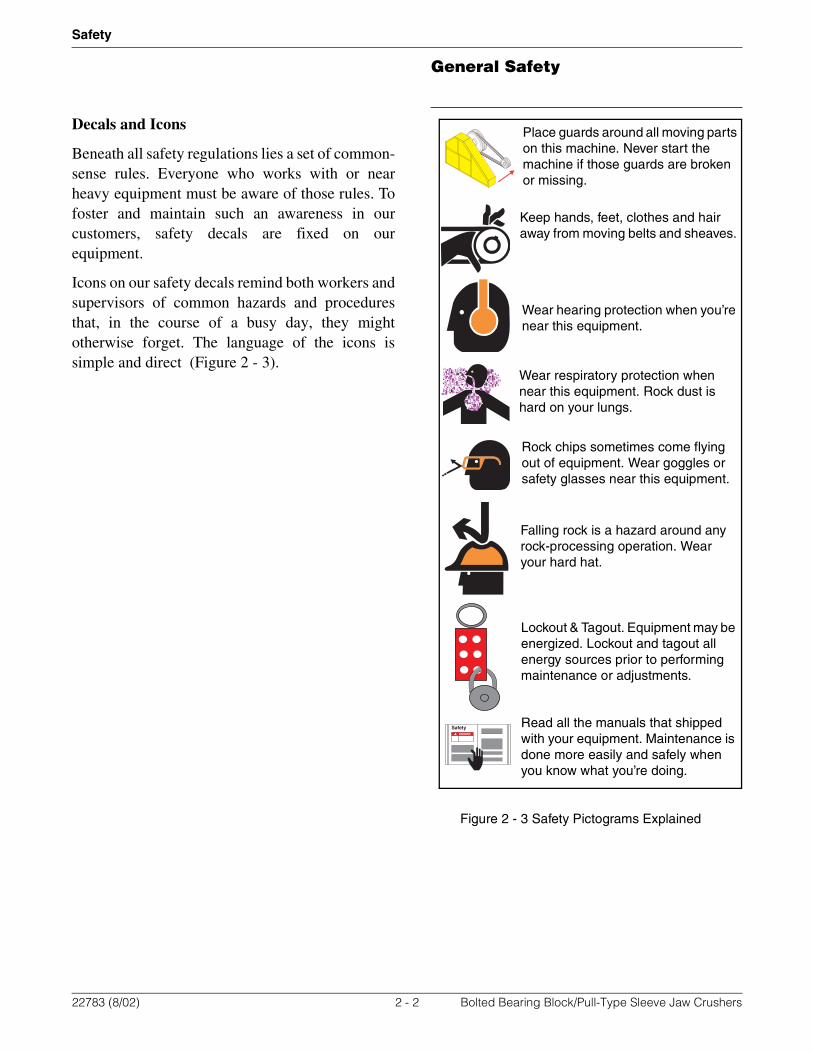
Icons on our safety decals remind both workers andsupervisors of common hazards and proceduresthat, in the course of a busy day, they mightotherwise forget. The language of the icons issimple and direct (Figure 2 - 3).
Figure 2 - 3 Safety Pictograms Explained
Place guards around all moving parts on this machine. Never start the machine if those guards are broken or missing.
Keep hands, feet, clothes and hair away from moving belts and sheaves.
Wear hearing protection when you’re near this equipment.
Wear respiratory protection when near this equipment. Rock dust is hard on your lungs.
Rock chips sometimes come flying out of equipment. Wear goggles or safety glasses near this equipment.
Falling rock is a hazard around any rock-processing operation. Wear your hard hat.
Read all the manuals that shipped with your equipment. Maintenance is done more easily and safely when you know what you’re doing.
Lockout & Tagout. Equipment may be energized. Lockout and tagout all energy sources prior to performing maintenance or adjustments.
22783 (8/02) 2 - 2 Bolted Bearing Block/Pull-Type Sleeve Jaw Crushers

Decal Location
Safety
Decal Location
NOTES:1. ASSEMBLY IS FOR ALL JAW CRUSHERS. DECAL LOCATIONS AS SHOWN, OR AS CLOSE AS POSSIBLE.2. ITEMS MARKED * ARE ON PARTS LIST 03042ED (JAW OIL LUBE EMBLEMS).
STAMP SERIAL NO. IN PARENT METAL(SEE P/L 01376EAS)
1-19 04494-100-04*
1-19 04494-100-01
1-3 04493-0231-4 07073-015
1-17 04418-031
STAMP SERIAL NO. IN PARENT METAL(SEE P/L 01376EAS)
OR
NOTE: WIRE TIE DECALAROUND GROOVED FLYWHEEL. (SEE P/L 05077SBK, DECAL P/N 04490-026).
Grease must extrude from the seals at all times to produce an effectivedust & moisture seal. Greasing intervals must be established to maintain this visible grease slick.
Every 1000 hours or seasonally, drain the supply tank and fill with flushing oil. Proceed with flushing operation. See specific instructions in Operations Manual.
Brand Names: Ambient Temperature Guide - (Above 32˚f) [Below 32˚f]Chevron Gear Compound EP (220) [150] Exxon Spartan EP (220) [150]Shell Omala EP (220) [150] Texaco Meropa (220) [150] Mobil Mobilgear (630) [629]
DANGER
Safety
Refer to Operation & Maintenance Manual fordetailed lubrication instructions.
Pitman & Side Bearings:
Seals: Lubricant: Lithium base, extreme pressure type, grade 2 grease.
Lubricant: Extreme pressure lubricating oil.Fill supply tank with recommended lubricant.
Roller Bearing Crusher Circulating Oil System
04494-100-04a
Refer to Operation & Maintenance Manual fordetailed lubrication instructions.
Lubricant: Lithium base, extreme pressure type, grade 1 grease.
Roller Bearing Crusher Grease Lubrication
Bearings & Seals: Grease must extrude from the seals at all times to produce an effectivedust & moisture seal. Greasing intervals must be established to maintain this visible grease slick.
Caution: Over lubrication will result in elevated operating temperatures.
04494-100-01a
DANGER
Safety
Brand Names:Chevron Dura-Lith EP1 Shell Alvania EP1Exxon Lidok EP1 Texaco Multifak EP1Mobil Mobilux EP1
Jaw, Impact Breaker, Hammermill
A Terex Company
SERIAL NUMBER
CEDAR RAPIDS, IOWA U.S.A.
MODEL NUMBER
DATE OFMANUFACTURE
4493-023
Crushing & Screening PatentsBuilt under one or more of the following patents:
United States:
4,454,994 - 4,477,031 - 4,571,112 - 4,699,326 - 4,717,084 - 4,773,604 - 4,896,838 - 4,919,348 - 4,919,349 - 4,925,114 - 5,083,714 - 5,111,569 - 5,005,772 - 5,004,169 -5,996,916 - 5,312,053 - 5,350,125 - 5,718,390 - 5,875,981 - 5,927,623 - 5,718,391 - 5,799,886 - 5,803,382 - 5,944,265 - 5,971,306 - 5,810,268 - 6,070,819 - 6,070,820 -6,089,481 - 6,126,101 - 6,149,086 - 6,155,507 - 6,161,650 - 6,189,820
Canada:
1,282,391 - 1,313,170 - 2,015,298 - 2,015,299 - 2,112,946.
France:
9010205
Great Britain:
2213398 - 2127500
New Zealand:
222,991 - 228,746 - 212,988Australia:
534,673 - 534,674 - 534,675 - 548,832 - 552,227 - 557,149 - 557,477 - 569,405 - 579,784 - 615,281
Other Patents Pending.
04418-031y
A Terex Company
1-16 04494-104-01 1-15 04418-542 1-16 04494-104-01 1-15 04418-542
Made In United States of America04418-955d
1-14 04418-955
EQUIPMENT DAMAGE HAZARDMay cause damage to motor or crusher.
Keep crusher pulley free of dust and dirt buildup to avoid shaking of machine.
04492-005b
CAUTION
1-11 04492-005
04490-103-011-1004490-103-011-10
1-8 04490-031
DANGERENTANGLEMENT HAZARD
EQU
IPM
ENT
LO
CK
ED
OU
T
DANG
ER
DANG
ER PELIG
RO
DANG
ER
LOC
KED
O
UT
Do not reach into unguarded machine, you can be pulled in.
Death or serious injury will result.
Keep all guards in place.
SWITCH OFF and LOCKOUT & TAGOUT equipment before opening or removing guards. 04490-031
EQUIPMENT DAMAGE HAZARDMay cause damage to motor or crusher.
Keep crusher pulley free of dust and dirt buildup to avoid shaking of machine.
04492-005b
CAUTION
1-11 04492-005
1-8 04490-031
DANGERENTANGLEMENT HAZARD
EQU
IPM
ENT
LO
CK
ED
OU
T
DANG
ER
DANG
ER PELIG
RO
DANG
ER
LOC
KED
O
UT
Do not reach into unguarded machine, you can be pulled in.
Death or serious injury will result.
Keep all guards in place.
SWITCH OFF and LOCKOUT & TAGOUT equipment before opening or removing guards. 04490-031
PELI
GR
OD
AN
GER
EQU
IPM
ENT
LOC
KED
OU
T
DA
NG
ERLO
CK
EDO
UT
HEARING HAZARDMay cause loss or degradationof hearing over a period of time.Wear proper hearing personal protection equipment.
Wear proper respiratory personal protective equipment.
May cause difficulty in breathing.
RESPIRATORY HAZARD
FALLING MATERIALMay cause death, or severe personal injury.Wear proper head personal protective equipment.
Wear proper eye personal protective equipment.
May cause loss or degradation of eye sight.
FLYING MATERIAL READ MANUALSRead all manuals prior to operation.DO NOT OPERATE equipment if you do not understand the information in the manuals.Consult your supervisor, the owner, or the manufacturer.
LOCKOUT & TAGOUTEquipment may be energized.Lockout and Tagout all energy sources priorto performing maintenance or adjustments.
04490-103-01
DANGER
DANGER
ENTANGLEMENT HAZARDDo not reach into unguarded machine, you can be pulled in.Death or serious injury will result.
Keep all guards in place.
NOTICEWARNING
22783 (8/02) 2 - 3 Bolted Bearing Block/Pull-Type Sleeve Jaw Crushers

Personal Safety
Safety
Personal Safety
This equipment is designed with the safety of allpersonnel in mind. Never attempt to change,modify, eliminate or bypass any of the safetydevices installed at the factory. Guards, covers andshields installed around moving parts at the factoryare meant to prevent accidental injury to operatorsand other personnel. Do not remove them.
Sometimes, at a customer’s request,equipment is shipped withoutcertain features such as a drivesheave. When this occurs, we attacha warning decal to alert installersthat the related guard or other safetyfeature is missing. In such cases it isthe customer’s responsibility toguard the machine properly.
Make sure that everyone working on or near thisequipment is familiar with safety precautions. Werecommend the following basic safety practices:
• Read all danger, warning, caution and noticesigns.
• Always lock out and tag out involved energysources before performing maintenance oradjustments on this equipment. Make itimpossible for anyone to start this machinewhile others work on it or in it.
• Never remove any guard, cover or shield whenthis equipment is in motion.
• Replace guards, covers and shields when thetask for which you removed them is finished.
• Block parts as necessary to prevent theirsudden movement while people are working onthe machine.
• Never attempt to clear away jammed feedmaterial, discharge material or other stoppagewhile the machine is running. Stop theequipment, lock out and tag out beforetouching this machine with your tools or yourhands.
• Wear proper personal protective equipment,including eye protection, hard hat and safetyshoes, whenever you’re near this machinewhile it is running.
• Dress appropriately in every way. Never wearloose clothes, long hair, coat tails, jewelry,pockets full of tools or any other item that couldget caught in moving parts.
• Know where your fellow workers are. Alwayslook around and inside this machine beforestarting it. Make sure nobody is in the way ofmoving parts or working on the machine.
• Lift with your legs, not with your back. Keepthe weight close to your body. If the load ismore than 40 lbs., get someone to help you.
• Never engage in horseplay when near thismachine, or any other.
• Report any defective machinery or equipmentand unsafe conditions or activity to your bossimmediately.
• Don’t limit safety practices to the few ruleslisted here. Think safety and act safely at alltimes.
• Most of all, know your equipment. Understandthe machinery, the conditions under which itoperates and what it is capable of doing.
DANGER
22783 (8/02) 2 - 4 Bolted Bearing Block/Pull-Type Sleeve Jaw Crushers

Lockout & Tagout
Safety
Work Area Safety
• Keep the work area as neat and clean aspractical.
• Keep all product safety signs clean, clear andcurrent.
• Make sure all electrical equipment is properlygrounded. Wet spots near electrical current areespecially dangerous.
• Store hazardous materials in restricted accessareas and mark them clearly. Federalregulations require special labeling of certainmaterials.
• Never start an engine in an enclosed spacewithout properly venting the exhaust.
• Do not smoke or allow smoking near fuels andsolvents. Never strike a spark or use an openflame near fuels and solvents.
• Store flammable fuels, solvents and gases insecure, well ventilated areas. Never allowfumes to accumulate in the storage area. Usenonflammable solvents for cleaning parts andequipment whenever possible.
• Know where fire extinguishers and other fire-suppression equipment are located. Learn howto use them effectively.
• Be alert and wary around any pressurizedsystem, hydraulic or pneumatic. High-pressureoils and gases are very dangerous.
Equipment & Tools
• Clean tools that are properly labeled and storedare safer tools. Keep your tools in good order.
• Keep drive belts and sheaves in good condition.Frayed belts or cracked sheaves are not onlydangerous, they cost you downtime.
• Always use mechanical assistance to lift heavyloads. Never overload a hoist, crane, jack orother lifting device. Check lifting tackleregularly; replace it at the first sign of stretch,fraying or other wear.
• Keep your equipment clean, free of dirt andgrease, so that loose, cracked or broken partsare more easily spotted. Replace defective partsas soon as they are discovered.
Lockout & Tagout
Code of Federal Regulationsnumber 1910.147 requires thatemployers establish and follow aLockout & Tagout procedure andtrain their employees in thatprocedure before any employee can operate,service or maintain any piece of power equipment.
Employers are required to make periodicinspections to see that their Lockout & Tagoutprocedures are being followed, and they mustmonitor and update their program on an ongoingbasis. Employees are responsible for seeing thatequipment is locked out and tagged out inaccordance with the employer’s policy.
To promote safety in its use, we ship a Lockout &Tagout Kit with the equipment. The kit and itscontents are illustrated in (Figure 2 - 4).
Figure 2 - 4 Lockout & Tagout Kit
Do Not Operate!
FEDERAL REGISTERAdditional instructions are available, but not in this block
of text. Please refer to the information provided with this
kit instead of trying to read this tiny text.
Additional instructions are available, but not in this block
of text. Please refer to the information provided with this
kit instead of trying to read this tiny text.Lockout -
Tagout Kit
Lockout - Tagout Kit
DANGERTHIS TAG & LOCK
TO BE REMOVED
ONLY BY THEPERSON LISTED
ON BACK.
DANGERTHIS TAG & LOCK
TO BE REMOVED
ONLY BY THEPERSON LISTED
ON BACK.
DANGERTHIS TAG & LOCK
TO BE REMOVED
ONLY BY THEPERSON LISTED
ON BACK.
DANGERTHIS TAG & LOCK
TO BE REMOVED
ONLY BY THEPERSON LISTED
ON BACK.
DANGERTHIS TAG & LOCK
TO BE REMOVED
ONLY BY THEPERSON LISTED
ON BACK.
DANGER
PELIGRO
Equipment Locked Out
by / Equipo Puesto Bajo
Llave Por ________
Date / Fecha ______
DANGER
PELIGRO
Equipment Locked Out
by / Equipo Puesto Bajo
Llave Por ________
Date / Fecha ______
DANGER
PELIGRO
Equipment Locked Out
by / Equipo Puesto Bajo
Llave Por ________
Date / Fecha ______
DANGER
PELIGRO
Equipment Locked Out
by / Equipo Puesto Bajo
Llave Por ________
Date / Fecha ______
DANGER
PELIGRO
Equipment Locked Out
by / Equipo Puesto Bajo
Llave Por ________
Date / Fecha ______
DANGER
PELIGRO
Equipment Locked Out
by / Equipo Puesto Bajo
Llave Por ________
Date / Fecha ______
DANGER
PELIGRO
Equipment Locked Out
by / Equipo Puesto Bajo
Llave Por ________
Date / Fecha ______
DANGER
PELIGRO
Equipment Locked Out
by / Equipo Puesto Bajo
Llave Por ________
Date / Fecha ______
DANGER
PELIGRO
Equipment Locked Out
by / Equipo Puesto Bajo
Llave Por ________
Date / Fecha ______
DANGER
PELIGRO
Equipment Locked Out
by / Equipo Puesto Bajo
Llave Por ________
Date / Fecha ______
22783 (8/02) 2 - 5 Bolted Bearing Block/Pull-Type Sleeve Jaw Crushers
Lockout & Tagout
Safety
What is Lockout & Tagout?
Lockout & Tagout is a procedure that’s designed toprevent absolutely the unexpected or accidentalstartup of equipment and to alert all workerswhenever it is unsafe to operate any piece ofequipment. When used as intended, Lockout &Tagout also protects personnel from energy storedin devices such as springs, accumulators, batteries,hydraulic systems, etc.
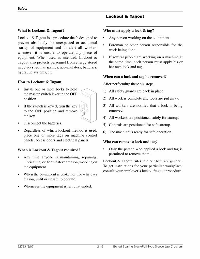
How to Lockout & Tagout
• Install one or more locks to holdthe master switch lever in the OFFposition.
• If the switch is keyed, turn the keyto the OFF position and removethe key.
• Disconnect the batteries.
• Regardless of which lockout method is used,place one or more tags on machine controlpanels, access doors and electrical panels.
When is Lockout & Tagout required?
• Any time anyone is maintaining, repairing,lubricating, or, for whatever reason, working onthe equipment.
• When the equipment is broken or, for whateverreason, unfit or unsafe to operate.
• Whenever the equipment is left unattended.
Who must apply a lock & tag?
• Any person working on the equipment.
• Foreman or other person responsible for thework being done.
• If several people are working on a machine atthe same time, each person must apply his orher own lock and tag.
When can a lock and tag be removed?
After performing these six steps:
1) All safety guards are back in place.
2) All work is complete and tools are put away.
3) All workers are notified that a lock is beingremoved.
4) All workers are positioned safely for startup.
5) Controls are positioned for safe startup.
6) The machine is ready for safe operation.
Who can remove a lock and tag?
• Only the person who applied a lock and tag ispermitted to remove them.
Lockout & Tagout rules laid out here are generic.To get instructions for your particular workplace,consult your employer’s lockout/tagout procedure.
22783 (8/02) 2 - 6 Bolted Bearing Block/Pull-Type Sleeve Jaw Crushers
Crusher Description & Information
General Jaw Crusher Information
Section 3 - General Jaw Crusher Information
Crusher Description & Information
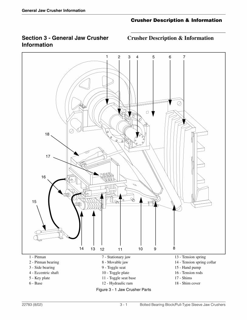
1 - Pitman 7 - Stationary jaw 13 - Tension spring2 - Pitman bearing 8 - Movable jaw 14 - Tension spring collar3 - Side bearing 9 - Toggle seat 15 - Hand pump4 - Eccentric shaft 10 - Toggle plate 16 - Tension rods5 - Key plate 11 - Toggle seat base 17 - Shims6 - Base 12 - Hydraulic ram 18 - Shim cover
Figure 3 - 1 Jaw Crusher Parts
1 2 3 4 5 6 7
891011121314
15
16
17
18
22783 (8/02) 3 - 1 Bolted Bearing Block/Pull-Type Sleeve Jaw Crushers

Crusher Description & Information
General Jaw Crusher Information
General Description
Cedarapids roller bearing jaw crushers are usedboth as primary and secondary crushers dependingon the size of the material to be crushed. They willbreak rock down to the size specified in oneoperation or to a size that can be further reduced bya secondary crusher such as a rollercone or asmaller jaw crusher. These crushers are made ofwelded type construction and can be used in eithera stationary or portable plant.
The jaw crusher consists of two readily separablesubassemblies; the base assembly and the shaft andpitman assembly. Refer to Figure 3 - 1. The baseassembly consists of the crusher base, stationaryjaw, key plates and adjusting mechanism. The shaftand pitman assembly is composed of the movingparts of the crusher; the eccentric shaft, pitman,movable jaw, side and pitman bearings, sidebearing housings, all bearing seals and spacers andthe two flywheels.
Operating Principle
The stationary jaw is wedged in place in the base bythe key plates and the movable jaw, which isattached to the pitman. The pitman is mounted onroller bearings on the eccentric portion of thecrusher shaft, the concentric ends of which aremounted in housed roller bearings rigidly attachedto the crusher base. The lower end of the pitman ishinged on one end of the toggle plate; the other endof the toggle plate oscillates in a groove in thetoggle bearing wedge, which is attached to thecrusher base.
The replaceable cast iron toggle plate serves as afuse or safety device in the crusher, as it will breakwhen uncrushable material such as a shovel toothpasses between the jaws. Due to the eccentric shaftand the toggle plate, a combination crushing anddownward motion is imparted to the pitman andmovable jaw as the shaft is revolved. Thehorizontal length of the crushing motion gradually
diminishes between the top and the bottom of themovable jaw, producing a long primary crushingstroke at the top of the jaw and a short stroke forcrushing to a more uniform size at the bottom.
Crusher Sizes
Jaw crusher size refers to the opening at the top ofthe crusher. This opening is rectangular and ismeasured from the top of the movable jaw (A) tothe top of the stationary jaw (B), and from side keyplates (C) to opposite side key plate (D) (Figure 3 -2). For example: a Model 3042 jaw crusher has anintake opening of 30 inches (762 mm) betweenjaws (A) to (B) and 42 inches (1067 mm) betweenkey plates (C) to (D). The dimensions will varyslightly due to the casting tolerances of jaws andkey plates.
Figure 3 - 2 Jaw Crusher Opening
Left/Right Side Designation
Right and left side of crusher are determined whenstanding facing the tension springs (Figure 3 - 2).
A
B
CD
LEFT SIDE RIGHT SIDE
22783 (8/02) 3 - 2 Bolted Bearing Block/Pull-Type Sleeve Jaw Crushers

Crusher Description & Information
General Jaw Crusher Information
Crusher Weights
The approximate weights listed in Table 3 - 1 arebased on clean new standard components. Weightsmay vary and listed weights should be consideredonly an approximation.
Model
Complete Crusher (Base, Pitman Assy, & Flywheels)
Pitman Assembly(Pitman Assy & Flywheels)
Flywheel Only(Each)
lbs kg lbs kg lbs kg
1016 5,306 2,406 2,844 1,293 690 314
1024 8,255 3,752 4,817 2,190 1,275 580
1036 12,551 5,705 7,449 3,386 1,223 556
1236 13,978 6,354 8,007 3,640 1,250 568
1242 19,521 8,873 12,120 5,509 2,098 954
1248 24,300 11,045 14,374 6,534 2,175 989
1524 12,305 5,593 6,771 3,078 1,215 552
1636 21,003 9,547 11,895 54,07 2,075 943
1642 33,998 15,454 19,642 8,928 2,741 1,246
1648 32,406 14,730 16,988 7,722 2,684 1,220
1824 12,426 5,648 6,771 3,078 1,215 552
1836 21,280 9,673 12,105 5,502 2,126 966
2236 24,903 11,320 14,266 6,485 2,785 1,266
2248 43,094 19,588 25,746 11,703 3,700 1,682
2436 46,737 21,244 22,861 10,391 3,462 1,574
2438 26,017 11,826 14,501 6,591 2,873 1,306
2540 45,000 20,455 18,950 8,614 4,200 1,909
2542 42,095 19,134 21,832 9,924 3,584 1,629
2742 48,520 22,055 25,842 11,746 4,194 1,906
3042 48,520 22,055 25,842 11,746 4,194 1,906
3054 52,740 23,973 27,525 12,511 4,194 1,906
3242 57,137 25,971 28,755 13,070 4,028 1,831
3648 79,653 36,206 39,524 17,965 5,560 2,527
3660 107,664 48,938 58,478 26,581 5,595 2,543
4242 58,838 26,745 28,755 13,070 4,028 1,831
4248 104,567 47,530 52,827 24,012 5,595 2,543
5460 196,258 89,208 102,715 46,689 10,570 4,805
5748 117,000 53,182 52,827 24,012 5,595 2,543
Table 3 - 1 Approximate Crusher and Component Weights
22783 (8/02) 3 - 3 Bolted Bearing Block/Pull-Type Sleeve Jaw Crushers
Crusher Description & Information
General Jaw Crusher Information
Lifting Crusher
To lift crusher, always fasten chain or cable tocrusher base. Never lift complete crusher withcables attached to flywheels or pitman. If onlypitman, shaft and bearing assembly is to beremoved from crusher base, fasten chain or cable tolifting lugs provided on top of pitman housing.
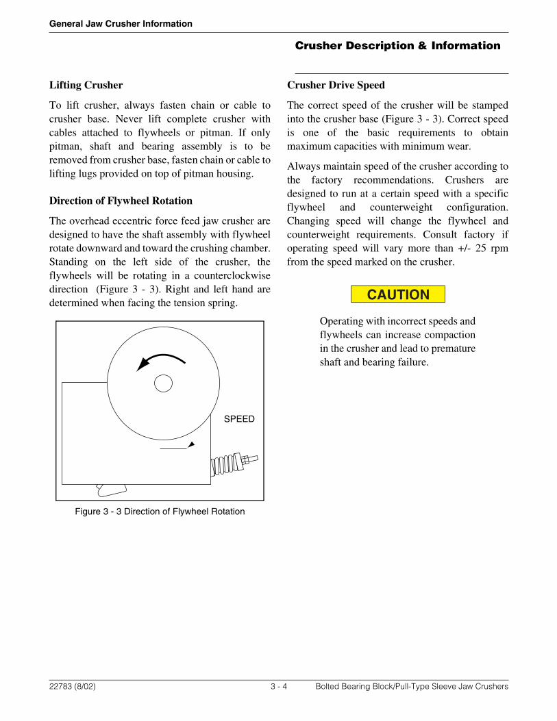
Direction of Flywheel Rotation
The overhead eccentric force feed jaw crusher aredesigned to have the shaft assembly with flywheelrotate downward and toward the crushing chamber.Standing on the left side of the crusher, theflywheels will be rotating in a counterclockwisedirection (Figure 3 - 3). Right and left hand aredetermined when facing the tension spring.
Figure 3 - 3 Direction of Flywheel Rotation
Crusher Drive Speed
The correct speed of the crusher will be stampedinto the crusher base (Figure 3 - 3). Correct speedis one of the basic requirements to obtainmaximum capacities with minimum wear.
Always maintain speed of the crusher according tothe factory recommendations. Crushers aredesigned to run at a certain speed with a specificflywheel and counterweight configuration.Changing speed will change the flywheel andcounterweight requirements. Consult factory ifoperating speed will vary more than +/- 25 rpmfrom the speed marked on the crusher.
Operating with incorrect speeds andflywheels can increase compactionin the crusher and lead to prematureshaft and bearing failure.
SPEED
CAUTION
22783 (8/02) 3 - 4 Bolted Bearing Block/Pull-Type Sleeve Jaw Crushers

Crusher Description & Information
General Jaw Crusher Information
Maximum & Minimum Crusher Settings
Cedarapids has established limits for the dischargeopening of each crusher. For safe and efficientoperation, the following maximum and minimumopenings should govern crushing extremes. Referto Table 3 - 2.
Capacity of Crusher
Crusher capacity is measure both by the size ofmaterial that can be fed into the crusher andthroughput of the crusher. In general, the maximumfeed size for jaw crushers is 80% of the jawopening in sand and gravel applications and 90% ofthe jaw opening in quarry applications. Forexample, a 3042 crusher with a jaw opening of 30”by 42” will have a maximum feed size of 24” by33.6” in sand and gravel applications and 27” by37.8” in quarry applications. These are generalguidelines and may vary in certain applications.
Crusher throughput capacities are based on averageconditions and will vary widely with differenttypes of rock and stone, uniformity of feed andmoisture content of material being crushed.Crusher throughput and gradation information isavailable by contacting your Cedarapidsdistributor.
SizeMinimum Maximum
inches mm inches mm
1016 3/4 19 3 1/2 89
1020 3/4 19 3 1/2 89
1024 3/4 19 3 1/2 89
1036 1 1/2 38 3 1/2 89
1236 1 1/2 38 5 127
1242 1 1/2 38 5 127
1248 1 1/2 38 5 127
1524 1 1/2 38 5 127
1636 1 1/2 38 5 127
1642 1 1/2 38 5 127
1648 1 1/2 38 5 127
1824 1 1/2 38 5 127
1836 1 1/2 38 5 127
2236 2 1/2 64 6 152
2248 2 1/2 64 6 152
2436 2 1/2 64 6 152
2438 4 1/2 114 8 203
2542 3 1/2 89 10 254
2742 3 1/2 89 10 254
3042 4 102 13 330
3054 3 1/2 89 13 330
3242 4 102 13 330
3648 4 102 13 330
3660 4 102 13 330
4242 14 356 23 584
4248 4 102 13 330
5460 6 152 20 508
5748 19 483 28 711
Table 3 - 2 Closed Stroke Setting Limits
22783 (8/02) 3 - 5 Bolted Bearing Block/Pull-Type Sleeve Jaw Crushers

Crusher Description & Information
General Jaw Crusher Information
Crusher Dimensions
Figure 3 - 4 Crusher Dimensions to nearest inch and mm
ledoM 6101 0201 4201 6301 6321 2421 8421 4251 6361 2461 8461 4281 6381 6322
A 045101
840221
545411
840221
840221
650241
950051
555931
160551
170081
665761
650241
465261
560561
B ––
––
––
––
––
––
––
––
––
375581
––
––
––
––
C 140401
640711
640711
640711
155921
555931
650241
755441
360061
670391
070871
755441
360061
775591
D 42016
82017
82017
82017
23018
33048
53098
63519
140401
640711
140401
63519
140401
840221
E 62066
82017
82017
82017
33048
43568
53098
93099
245601
840221
245601
93099
245601
945421
F 850741
270381
270381
185502
185502
890942
4010462
760071
295332
995152
495832
775591
295332
295332
G 22065
62066
72586
140401
140401
745911
355431
72586
140401
745911
355431
72586
140401
340901
H 41553
41553
12535
81554
91084
02015
91084
81554
61504
02015
61504
91084
61504
71034
ledoM 8422 6342 8342 2452 2472 2403 4503 2423 8463 0663 2424 8424 8475 0645
A 975002
885322
760071
280802
885322
885322
885322
390632
7015172
8115992
3015162
3215213
8315053
9415873
B 185502
190132
––
580612
885322
191132
191132
995152
3110782
––
9010772
6210023
1410853
2510683
C 380112
980622
775591
390632
297332
297332
297332
5015662
0210503
5215713
5015662
7310843
7310843
2710734
D 250231
160551
050721
360061
265751
265751
360061
575091
280802
685812
575091
690442
690442
7215223
E 450731
160551
945421
560561
466261
466261
466261
775591
485312
885322
775591
1015652
1015652
0310033
F 995152
495832
295332
595142
995152
995152
0115972
995152
1015652
9115203
995152
0210503
0210503
0415553
G 355431
340901
340901
545411
745911
745911
965571
745911
250231
870891
745911
555931
555931
760071
H 61504
71034
81554
91084
71034
71034
02015
22065
02015
82117
22065
02015
02015
81554
D
H G
F
E
C
AB Tension Spring Location on 1016 & 1020
22783 (8/02) 3 - 6 Bolted Bearing Block/Pull-Type Sleeve Jaw Crushers
Mounting & Set-up
Set-up & Operation
Section 4 - Set-up & Operation
Mounting & Set-up
The jaw crusher may be installed on a portableplant or as a component for installation in astationary plant or customer supplied portableplant. Mounting a jaw crusher requires carefulplanning to ensure:
• mounting structure is capable of supporting theweight and forces generated by an operatingjaw crusher.
• adequate clearance has been left around thecrusher to allow safe operation withoutinterference.
• crusher flywheel and drive are appropriatelyguarded to prevent access during operation.
• provisions are made allowing the power sourceto be locked out and tagged out.
• guard rails and walkways are installed wherenecessary.
• a means of feeding material to the crusher andremoving crushed material from under thecrusher are provided.
Mounting Crusher
All foundations and crusher supports must bedesigned by a qualified engineer to meet local coderequirements. Information needed to design thecrusher foundation or support may be obtainedfrom Cedarapids.
When installing crusher in a stationary plant, placeon an adequately designed foundation. There mustbe ample clearance maintained between crusherdischarge and receiving conveyor for the materialto discharge without rubbing end of pitman.Consideration for overhead clearance must also bemade should removal of the pitman becomenecessary.
The crusher must be perfectly level across thelength of the shaft (side-to-side) to maintain evenload on all the bearings and ensure properlubrication of the bearings.
Mounting Clearance
Adequate clearances must be maintained above the crusher for feeding material into it as well as facilitate maintenance of the crusher. Likewise, adequate clearance must be below the crusher to allow for material to exit the crusher without buildup.
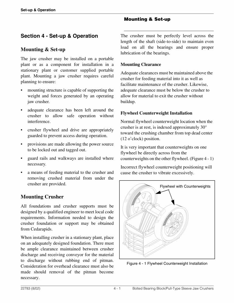
Flywheel Counterweight Installation
Normal flywheel counterweight location when the crusher is at rest, is indexed approximately 30° toward the crushing chamber from top dead center (12 o’clock) position.
It is very important that counterweights on one flywheel be directly across from the counterweights on the other flywheel. (Figure 4 - 1)
Incorrect flywheel counterweight positioning will cause the crusher to vibrate excessively.
Figure 4 - 1 Flywheel Counterweight Installation
Flywheel with Counterweights
22783 (8/02) 4 - 1 Bolted Bearing Block/Pull-Type Sleeve Jaw Crushers
Mounting Crusher
Set-up & Operation
Guarding
It is the responsibility of the equipment owner andoperators to ensure that adequate guarding isdesigned and built. The following are situationsthat should be considered when installing a jawcrusher. Each installation is unique with specialhazards that must be considered and guarded. Theentire installation should be reviewed by aqualified safety engineer before operation begins.
• The drive system from the drive shaft on thepower unit to the flywheels on the crushershould be guarded to prevent access duringoperation. This includes the v-belts and bothflywheels.
• The power unit must provide a means todisengage the power source and install a lockand hasp to prevent accidental starting of thecrusher. This could include accidental startingof the engine if a wrench falls onto the starteror start switch.
• The area between the crusher and feedershould be guarded to prevent access duringoperation.
• Any conveyor, feeder or other equipment thatis overhead or accessible by workers while thecrusher is operating must be guarded toprevent any worker from contacting movingparts. This equipment must also be guarded toprevent material from dropping off theequipment and hitting a worker.
• Guarding, handrails and walkways must bedesigned and operated in compliance with allcurrent applicable OSHA, MSHA, NationalElectric Code (NEC), federal, state, and localregulations.
22783 (8/02) 4 - 2 Bolted Bearing Block/Pull-Type Sleeve Jaw Crushers

Operation
Set-up & Operation
Operation
Prior To Starting
Perform all daily and periodic lubrication andmaintenance tasks listed in Section 5.
Shut down, lock out and tag out alldrives, power sources, and electricpower panels prior to performingany maintenance.
Starting Crusher
Grease Lube Systems
1) Start or engage crusher drive.
2) Allow the crusher to run empty for a few minutes until the lubricant is warmed up.
3) Start under-crusher conveyor.
4) Start feeder.
Oil Lube Systems
1) If the crusher is equipped with the optional oil lubrication system with oil reservoir heaters, turn on heaters and allow oil to warm to operating temperature.
2) If the crusher is equipped with the optional oil lubrication system with optional cycle timer, switch the Day-Night switch to Day.
3) If the crusher is equipped with the optional oil lubrication system operate as follows.
A) Start oil lubrication pump.
B) Control valves regulate the oil flow to the bearings. Flow to each bearing is controlled independently.
C) Fully open all valves. Brass indicators in the flow indicator tubes will rise to their highest points in the tubes.
D) Allow the crusher to run until the oil is warmed up.
E) Partially close the valves until all the indicators are at the same level.
4) Start or engage crusher drive.
5) Allow the crusher to run empty for a few minutes.
6) Start under-crusher conveyor.
7) Start feeder.
Cold Weather Startup Notes
• Allow the crusher extra time to run empty toensure the lubricant is warmed.
• If the crusher is hard to start, change to lighterlubricant. Refer to lubrication instructions formore information.
WARNING
22783 (8/02) 4 - 3 Bolted Bearing Block/Pull-Type Sleeve Jaw Crushers

Operation
Set-up & Operation
During Operation
Throughout the daily operating period the operatorshould check for unusual sounds or other signs ofabnormal operation that warn of future trouble ifnot promptly corrected.
• Check crusher bearings for the appearance ofoverheating. Do not operate crusher ifbearings overheat until the cause is determinedand corrected.
• Ensure tension springs are tight enough tokeep the toggle plate from clattering when thecrusher is running empty. After changing thecrusher discharge opening or replacing thetoggle plate listen for a clattering or poundingnoise, indicating the tension springs are tooloose. Adjust tension springs before resumingoperation.
• Observe the stationary jaw for slight up anddown movement. If such movement is visible,tighten the key plates. If crusher is operatedwith loose key plates, the resulting movementof the stationary jaw will cause unnecessarywear on the jaw and base as well as reduce thecapacity of the crusher.
Oil Lubrication System
• Periodically check the level of the flowindicators. If the level falls in any of the tubes,it could be a sign of bearing problems orclogged filters.
• The filter gauge shows the pressure in the feedline to the filter. Readings will vary withambient temperature, type of lubricant,operating temperature, etc.
• The suction gauge will normally show little orno reading.
Stopping Crusher
1) Stop the feed to the crusher.
2) Allow the material in crusher to be fully crushed and empty out the crushing chamber.
3) Shut off the power to the crusher drive.
4) Shut off the power to the under-crusher conveyor.
Avoid stopping the crusher whenthe jaws are full of material.Restarting the loaded crusherproduces an excessive load on thepower unit and an extreme pull onthe belts. A plugged crusher shouldbe at least partially emptied by handbefore restarting.
CAUTION
22783 (8/02) 4 - 4 Bolted Bearing Block/Pull-Type Sleeve Jaw Crushers

Feeding The Crusher
Set-up & Operation
Feeding The Crusher
The most efficient operation of the crusher resultswhen the crushing chamber is kept full of materialand when a uniform method of feeding is used. Thecrusher should be kept full of material however,material should not be allowed to build up abovethe tops of the jaws.
Allowing material to build up to thepitman during crushing coulddamage the pitman. Do not allowmaterial to build up higher than thetops of the jaw dies.
Material Feed Size
Material typically found in sand and graveloperations has rounded corners. Shot materialtypically found in quarry operations tends to bemore cubical with square corners. Roundedmaterial requires a smaller nip angle so the jawscan grab and crush the material. Material that is notgrabbed by the jaws will slide up and down as thejaws open and close. This wears the jaws withoutproducing product. This material should beremoved from the crusher and broken up beforeattempting to crush again.
A rock breaker can be installed that will allowmaterial to be broken up in the crusher or feeder.
Always turn off the crusher andfeeder before using a rock breaker.
In general, the maximum feed size for jaw crushersis 80% of the jaw opening in sand and gravelapplications and 90% of the jaw opening in quarryapplications. For example, a 3042 crusher with ajaw opening of 30” by 42” will have a maximumfeed size of 24” by 33.6” in sand and gravelapplications and 27” by 37.8” in quarryapplications. These are general guidelines and mayvary in certain applications.
Do not use explosives in crusherchamber. The crushing chamber isnot designed to withstand the forcesgenerated by explosives. Explosivescan cause premature failure ofbearings and breakage of thepitman, eccentric shaft and base.
Running the crusher with oversizedor uncrushable material sliding onthe top of the pitman can damagethe pitman. Shut down and removeoversized material.
Clay
Clay tends to build up in the corrugations of thejaw. This reduces jaw capacity and could damagethe crusher. When crushing material containingclay, the crusher should be stopped periodicallyand clay should be cleaned from the jawcorrugations.
Material containing heavy clay should be scalpedto remove clay before feeding into the jaw crusher.
CAUTION
CAUTION
DANGER
WARNING
22783 (8/02) 4 - 5 Bolted Bearing Block/Pull-Type Sleeve Jaw Crushers

Adjusting Closed Side Setting (CSS)
Set-up & Operation
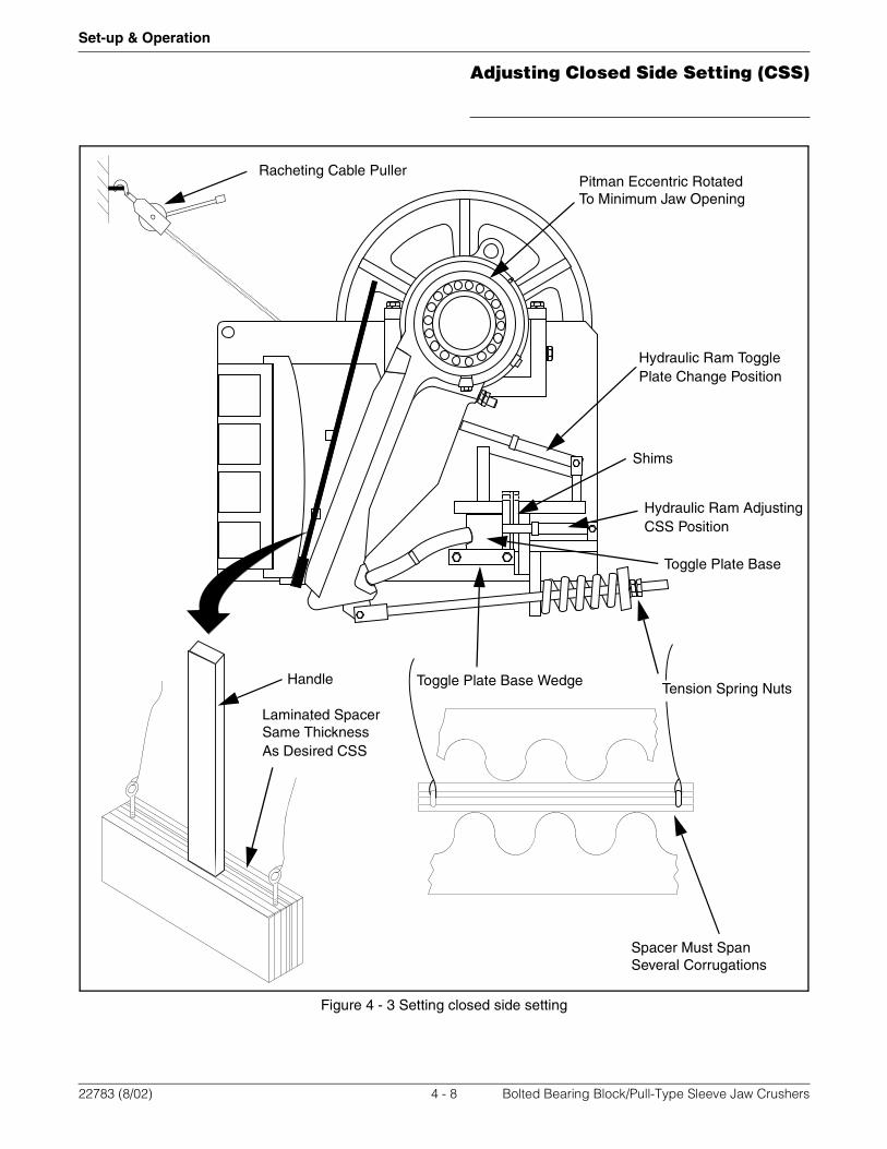
Adjusting Closed Side Setting (CSS)
The crusher discharge opening governs the size offinished material produced by the crusher.The sizeof the crusher discharge opening is changed byadding or removing shims from behind the toggleseat base. The opening is reduced by moving thebase toggle seat forward with the hydraulicmechanism and shimming behind the seat. Refer toFigure 4 - 3. Adjust as follows:
1) When the crushing chamber is completely empty, stop the jaw crusher drive and lock out the power source.
2) Some crushers are equipped with toggle plate base wedges which lock the toggle plate base during operation. This prevents any rocking movement of the base during operation, reducing wear on the toggle seat insert and on the end of the toggle plate.If your crusher is equipped with toggle plate base wedges, perform the following steps. Refer to Figure 4 - 2.
Figure 4 - 2 Toggle Plate Base Wedge
A) When the crusher opening is to be adjusted, loosen the four wedge tightening locknuts (2 per side) at the sides of the crusher base. Loosen 1/2 inch.
B) Insert a bar through the hole in each side of the crusher base side plate and through a slot in each of the support angles, to contact the wedges. Hit the bar with a sledge until wedge is loose and the toggle plate base is free to move.
3) Loosen tension spring nuts so that shim pack can be adjusted.
4) Install hydraulic rams to push toggle seat forward. Some crushers have two mounts near the bottom of the crusher used to adjust the crusher and a single mount around the midpoint of the pitman used to push the pitman forward when installing a toggle plate. Always install the rams in the lower holes when adjusting the closed side setting. Refer to Figure 4 - 3.
5) Attach hydraulic pump to ram(s).
6) Make a wooden spacer similar to that shown in Figure 4 - 3, to the exact thickness of the correct discharge opening. When lumber of proper width or thickness is not available, make up a lamination, including plywood, hard fibre board, or metal to obtain the correct thickness. Spacer must be wide enough to bridge between several jaw plate tips as shown in Figure 4 - 3. This is especially important when the desired setting is close to the minimum closed side setting of the crusher. Adding a handle to spacer block will make it easier to properly position at the bottom of the jaws.
7) Rotate and hold the flywheel so that the eccentric shaft closes the jaws as much as possible. Using a ratcheting cable puller (come-along) will make it easier to rotate and hold the flywheel in the desired position.
Wedge Toggle Plate Base
SupportSlot (for loosening wedge)
22783 (8/02) 4 - 6 Bolted Bearing Block/Pull-Type Sleeve Jaw Crushers
Adjusting Closed Side Setting (CSS)
Set-up & Operation
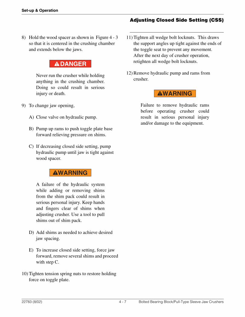
8) Hold the wood spacer as shown in Figure 4 - 3 so that it is centered in the crushing chamber and extends below the jaws.
Never run the crusher while holdinganything in the crushing chamber.Doing so could result in seriousinjury or death.
9) To change jaw opening,
A) Close valve on hydraulic pump.
B) Pump up rams to push toggle plate base forward relieving pressure on shims.
C) If decreasing closed side setting, pump hydraulic pump until jaw is tight against wood spacer.
A failure of the hydraulic systemwhile adding or removing shimsfrom the shim pack could result inserious personal injury. Keep handsand fingers clear of shims whenadjusting crusher. Use a tool to pullshims out of shim pack.
D) Add shims as needed to achieve desired jaw spacing.
E) To increase closed side setting, force jaw forward, remove several shims and proceed with step C.
10) Tighten tension spring nuts to restore holding force on toggle plate.
11) Tighten all wedge bolt locknuts. This draws the support angles up tight against the ends of the toggle seat to prevent any movement. After the next day of crusher operation, retighten all wedge bolt locknuts.
12) Remove hydraulic pump and rams from crusher.
Failure to remove hydraulic ramsbefore operating crusher couldresult in serious personal injuryand/or damage to the equipment.
DANGER
WARNING
WARNING
22783 (8/02) 4 - 7 Bolted Bearing Block/Pull-Type Sleeve Jaw Crushers
Adjusting Closed Side Setting (CSS)
Set-up & Operation
Figure 4 - 3 Setting closed side setting
Racheting Cable PullerPitman Eccentric Rotated
Shims
Toggle Plate Base
Handle
Laminated Spacer
Spacer Must Span
To Minimum Jaw Opening
Several Corrugations
Same Thickness As Desired CSS
Tension Spring Nuts
Hydraulic Ram Toggle
Hydraulic Ram Adjusting
Toggle Plate Base Wedge
Plate Change Position
CSS Position
22783 (8/02) 4 - 8 Bolted Bearing Block/Pull-Type Sleeve Jaw Crushers
General Lubrication Information
Lubrication & Maintenance
Section 5 - Lubrication & Maintenance
General Lubrication Information
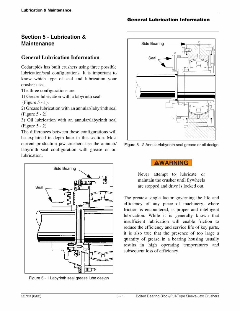
Cedarapids has built crushers using three possiblelubrication/seal configurations. It is important toknow which type of seal and lubrication yourcrusher uses.The three configurations are:1) Grease lubrication with a labyrinth seal (Figure 5 - 1).2) Grease lubrication with an annular/labyrinth seal(Figure 5 - 2).3) Oil lubrication with an annular/labyrinth seal(Figure 5 - 2).The differences between these configurations willbe explained in depth later in this section. Mostcurrent production jaw crushers use the annular/labyrinth seal configuration with grease or oillubrication.
Figure 5 - 1 Labyrinth seal grease lube design
Figure 5 - 2 Annular/labyrinth seal grease or oil design
Never attempt to lubricate ormaintain the crusher until flywheelsare stopped and drive is locked out.
The greatest single factor governing the life andefficiency of any piece of machinery, wherefriction is encountered, is proper and intelligentlubrication. While it is generally known thatinsufficient lubrication will enable friction toreduce the efficiency and service life of key parts,it is also true that the presence of too large aquantity of grease in a bearing housing usuallyresults in high operating temperatures andsubsequent loss of efficiency.
Side Bearing
Seal
Side Bearing
Seal
WARNING
22783 (8/02) 5 - 1 Bolted Bearing Block/Pull-Type Sleeve Jaw Crushers
General Lubrication Information
Lubrication & Maintenance
Cleanliness in the handling of lubricants, fittings,grease guns and the openings and plugs of housingsis of vital importance. Foreign substancescontaminate lubricant. Be sure that all fittings andopenings are thoroughly cleaned of all foreignsubstances before starting to inject lubricant. Inusing the grease gun always see that the gun makesproper contact with the cleaned fittings and that thenozzle has not been allowed to touch uncleansurfaces.
Never mix different types oflubricant within the crusher. Alwaysdrain and flush out old lubricantbefore changing to a differentbrand, as chemical breakdown canoccur in lubricant mixtures.
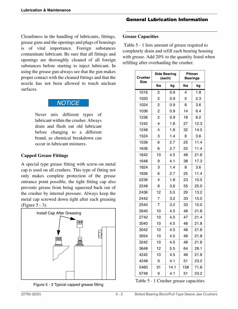
Capped Grease Fittings
A special type grease fitting with screw-on metalcap is used on all crushers. This type of fitting notonly makes complete protection of the greaseentrance point possible, the tight fitting cap alsoprevents grease from being squeezed back out ofthe crusher by internal pressure. Always keep themetal cap screwed down tight after each greasing(Figure 5 - 3).
Figure 5 - 3 Typical capped grease fitting
Grease Capacities
Table 5 - 1 lists amount of grease required to completely drain and refill each bearing housing with grease. Add 20% to the quantity listed when refilling after overhauling the crusher.
NOTICE
Install Cap After Greasing
Crusher Size
Side Bearing (each)
Pitman Bearings
lbs kg lbs kg
1016 2 0.9 4 1.8
1020 2 0.9 5 2.3
1024 2 0.9 8 3.6
1036 2 0.9 14 6.4
1236 2 0.9 18 8.2
1242 4 1.8 27 12.3
1248 4 1.8 32 14.5
1524 3 1.4 8 3.6
1536 6 2.7 25 11.4
1636 6 2.7 25 11.4
1642 10 4.5 48 21.8
1648 9 4.1 38 17.3
1824 3 1.4 8 3.6
1836 6 2.7 25 11.4
2236 4 1.8 23 10.5
2248 8 3.6 55 25.0
2436 12 5.5 29 13.2
2442 7 3.2 33 15.0
2540 7 3.2 33 15.0
2640 10 4.5 48 21.8
2742 10 4.5 47 21.4
3040 10 4.5 48 21.8
3042 10 4.5 48 21.8
3054 10 4.5 48 21.8
3242 10 4.5 48 21.8
3648 12 5.5 64 29.1
4242 10 4.5 48 21.8
4248 9 4.1 51 23.2
5460 31 14.1 158 71.8
5748 9 4.1 51 23.2
Table 5 - 1 Crusher grease capacities
22783 (8/02) 5 - 2 Bolted Bearing Block/Pull-Type Sleeve Jaw Crushers
Grease Lube Labyrinth Seal Crush-ers
Lubrication & Maintenance
Lubricating Stored Equipment
Idle equipment whether new or used; must beturned over at least every 30 days either by poweror hand to redistribute the lubricant. Rotating thebearing assemblies periodically redistributeslubricant on all surfaces of the bearing.
Failure to rotate bearings when crusher is idle willpermit lubricant to drain to the bottom of thebearing assembly. Moisture from condensationcould collect and set up a chemical reaction in thebearing assemblies know as corrosive staining.These stained areas are a positive point forpremature bearing failures, as flaking will start atthese points when the equipment is put back intooperation.
Bearing Temperature
Normal operating bearing temperature should be100° to 150°F (38° to 66°C) but in warm climatesmay reach 180° to 200°F (82° to 93°C). Excessiveheat in the bearings may indicate the presence offoreign material between the fixed and rotatingseals, and it is recommended that grease be injectedinto the bearings through the lubrication fittings toforce the foreign material out and reduce heatgeneration. The reduction of temperature in thebearing will be slow because heat will continue toexist until the internal pressure inside the housingforces out the excess lubricant.
If the crusher stops, back up the shaft assemblyone-half a revolution to see if foreign material hasbeen expelled. Repeat process until shaft assemblyturns over easily; if the grease seals do not breakloose,” then a complete overhaul is the onlysolution.
Grease Lube Labyrinth Seal Crushers
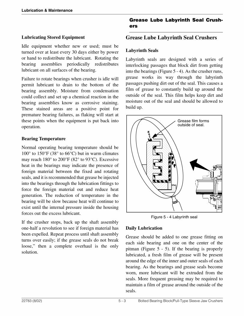
Labyrinth Seals
Labyrinth seals are designed with a series ofinterlocking passages that block dirt from gettinginto the bearings (Figure 5 - 4). As the crusher runs,grease works its way through the labyrinthpassages pushing dirt out of the seal. This causes afilm of grease to constantly build up around theoutside of the seal. This film helps keep dirt andmoisture out of the seal and should be allowed tobuild up.
Figure 5 - 4 Labyrinth seal
Daily Lubrication
Grease should be added to one grease fitting oneach side bearing and one on the center of thepitman (Figure 5 - 5). If the bearing is properlylubricated, a fresh film of grease will be presentaround the edge of the inner and outer seals of eachbearing. As the bearings and grease seals becomeworn, more lubricant will be extruded from theseals. More frequent greasing may be required tomaintain a film of grease around the outside of theseals.
Grease film formsoutside of seal.
22783 (8/02) 5 - 3 Bolted Bearing Block/Pull-Type Sleeve Jaw Crushers

Grease Lube Labyrinth Seal Crush-ers
Lubrication & Maintenance
Lubricate with a lithium base, extreme pressure,Grade 1 grease.
Typical brand names are: Chevron Dura-Lith EP1,Exxon Lidok EP1, Mobil Mobilux EP1, ShellAlvania EP1, Texaco Multifak EP1.
1 - Pitman grease fitting 3 - Side bearing grease fitting2 - Pitman magnetic drain plug 4 - Side bearing magnetic drain plug
Figure 5 - 5 Grease lubrication points
1
2
3
4
Side Bearing
Pitman Bearing1
2
4
22783 (8/02) 5 - 4 Bolted Bearing Block/Pull-Type Sleeve Jaw Crushers

Grease Lube Labyrinth Seal Crush-ers
Lubrication & Maintenance
Changing Lubricant
Under normal conditions, it is recommended thatgrease be changed every 1000 hours of actualcrushing or once each year, whichever occurs first.
1) Before changing lubricant, run crusher long enough to heat the existing lubricant to a consistency that allows it to flow freely.
2) Clean area around drain plugs and grease fittings then remove plugs and fittings to drain free flowing lubricant. Refer to Figure 5 - 5.
3) Replace drain plugs and inject flushing oil in each bearing to fill pitman barrel and base housing to top of fill hole. An extreme pressure 150 viscosity, Grade 46 flushing oil should be used.
4) Replace the grease fittings.
5) Run the crusher empty for at least 10 minutes.
6) Stop unit and remove drain plugs to drain flushing oil.
Running crusher slowly whiledraining flushing oil will expeditethe draining.
7) Thoroughly clean and replace the magnetic drain plugs and inject a recommended grease in each bearing.
8) Replace and tighten the grease fittings and fitting caps.
Failure to thoroughly clean drainplugs and fittings before installationcould cause grease contamination.Grease must be kept clean toprevent damage to bearings.
9) Refill bearing housing with grease. In determining the amount of grease to be used be governed by the fact that a pint of grease weighs slightly less than one pound. It is recommended in a complete overhaul, that 20% more lubricant be added in both of the side bearings and in the pitman.
When starting a new crusher for the first time, orafter an overhaul, apply a liberal amount of gearlube to the area between the pitman and sidebearing seals. Apply oil until grease inside bearingbegins to extrude from the grease seals. Thisprecautionary measure insures lubrication until theactual lubricating system begins to function. Acrusher which has been idle for a period of time andexposed to the weather should receive the sameconsideration.
At the end of a season’s operation it isrecommended that the lubricant be drained, flushedand new lubricant be injected into the housing. Thecrusher should be operated without load forapproximately one hour to permit new lubricant tobe evenly distributed in the bearing assembly andhousing. New lubricant in the housing would tendto eliminate the possibility of corrosive reactionswhich might be evident if worked” and oxidized”lubricant is allowed to remain in the housing whenthe crusher is not in use for long periods of time.
NOTICE
CAUTION
22783 (8/02) 5 - 5 Bolted Bearing Block/Pull-Type Sleeve Jaw Crushers
Grease Lube Annular/Labyrinth SealCrushers
Lubrication & Maintenance
Grease Lube Annular/Labyrinth Seal Crushers
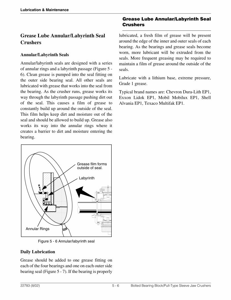
Annular/Labyrinth Seals
Annular/labyrinth seals are designed with a seriesof annular rings and a labyrinth passage (Figure 5 -6). Clean grease is pumped into the seal fitting onthe outer side bearing seal. All other seals arelubricated with grease that works into the seal fromthe bearing. As the crusher runs, grease works itsway through the labyrinth passage pushing dirt outof the seal. This causes a film of grease toconstantly build up around the outside of the seal.This film helps keep dirt and moisture out of theseal and should be allowed to build up. Grease alsoworks its way into the annular rings where itcreates a barrier to dirt and moisture entering thebearing.
Figure 5 - 6 Annular/labyrinth seal
Daily Lubrication
Grease should be added to one grease fitting oneach of the four bearings and one on each outer sidebearing seal (Figure 5 - 7). If the bearing is properly
lubricated, a fresh film of grease will be presentaround the edge of the inner and outer seals of eachbearing. As the bearings and grease seals becomeworn, more lubricant will be extruded from theseals. More frequent greasing may be required tomaintain a film of grease around the outside of theseals.
Lubricate with a lithium base, extreme pressure,Grade 1 grease.
Typical brand names are: Chevron Dura-Lith EP1,Exxon Lidok EP1, Mobil Mobilux EP1, ShellAlvania EP1, Texaco Multifak EP1.
Grease film formsoutside of seal.
Annular Rings
Labyrinth
22783 (8/02) 5 - 6 Bolted Bearing Block/Pull-Type Sleeve Jaw Crushers

Grease Lube Annular/Labyrinth SealCrushers
Lubrication & Maintenance
1 - Pitman bearing grease fitting 4 - Side bearing magnetic drain plug2 - Pitman magnetic drain plug 5 - Side bearing outer seal grease fitting3 - Side bearing grease fitting
Figure 5 - 7 Grease lubrication points
Changing Lubricant
Under normal conditions, it is recommended thatgrease be changed every 1000 hours of actualcrushing or once each year, whichever occurs first.
1) Before changing lubricant, run crusher long enough to heat the existing lubricant to a consistency that allows it to flow freely.
2) Clean area around drain plugs and grease fittings then remove plugs and fittings to drain free flowing lubricant. Refer to Figure 5 - 7.
2
3
4
Side Bearing
Pitman Bearing1
2
4
5
22783 (8/02) 5 - 7 Bolted Bearing Block/Pull-Type Sleeve Jaw Crushers

Grease Lube Annular/Labyrinth SealCrushers
Lubrication & Maintenance
3) Replace drain plugs and inject flushing oil in each bearing to fill pitman barrel and base housing to top of fill hole. An extreme pressure 150 viscosity, Grade 46 flushing oil should be used.
4) Replace the grease fittings.
5) Run the crusher empty for at least 10 minutes.
6) Stop unit and remove drain plugs to drain flushing oil.
Running crusher slowly whiledraining flushing oil will expeditethe draining.
7) Thoroughly clean and replace the magnetic drain plugs and inject a recommended grease in each bearing.
8) Replace and tighten the grease fittings and fitting caps.
Failure to thoroughly clean drainplugs and fittings before installationcould cause grease contamination.Grease must be kept clean toprevent damage to bearings.
9) Refill bearing housing with grease. In determining the amount of grease to be used be governed by the fact that a pint of grease weighs slightly less than one pound. It is recommended in a complete overhaul, that 20% more lubricant be added in both of the side bearings and in the pitman.
When starting a new crusher for the first time, orafter an overhaul, apply a liberal amount of gearlube to the area between the pitman and sidebearing seals. Apply oil until grease inside bearingbegins to extrude from the grease seals. Thisprecautionary measure insures lubrication until theactual lubricating system begins to function. Acrusher which has been idle for a period of time andexposed to the weather should receive the sameconsideration.
At the end of a season’s operation it isrecommended that the lubricant be drained, flushedand new lubricant be injected into the housing. Thecrusher should be operated without load forapproximately one hour to permit new lubricant tobe evenly distributed in the bearing assembly andhousing. New lubricant in the housing would tendto eliminate the possibility of corrosive reactionswhich might be evident if worked” and oxidized”lubricant is allowed to remain in the housing whenthe crusher is not in use for long periods of time.
NOTICE
CAUTION
22783 (8/02) 5 - 8 Bolted Bearing Block/Pull-Type Sleeve Jaw Crushers

Oil Lube Annular/Labyrinth SealCrusher
Lubrication & Maintenance
Oil Lube Annular/Labyrinth Seal Crusher
System Overview
The oil lubrication system is standard on the 5460and optional on most other crusher models. Referto Figure 5 - 8. It is recommended for use on largercrushers or when the crusher will be operated incold environments. Oil is drawn from the reservoirby the oil pump. The oil pump is normally drivenby an electric motor. An optional flywheel drivenoil pump is available although, electric drive isusually preferred. The electric driven lube systemcan be started before engaging the crusher. Thisensures lubrication of the bearings the moment thecrusher is started.
The reservoir size is dependent upon the crushersize. Capacities will vary by crusher size. Thereservoir is set lower that the bearings so that oilflows by gravity from the bearings to the reservoir.
For operation in cold environments, an optionalreservoir heater and cycle timer are available. Theheaters are thermostatically controlled to maintainthe oil at a working temperature. A cycle timer canbe used to periodically start and stop theelectrically driven oil pump when the crusher is notrunning. This ensures that oil in the lines andbearing cavities is circulated back to be warmed inthe reservoir.
Oil is strained between the reservoir and pump andfiltered between the pump and bearings. A vacuumgage is mounted on the strainer. A pressure gaugeis mounted on the filter.
Oil from the filter runs through the flow controlvalves and indicator. Oil flow to each bearing isindividually controlled and monitored.
From the flow indicator, the oil flows into the topof each bearing and flows by gravity through thebearing. Oil collects at the bottom of each of thebearing cavities and returns by gravity to the
reservoir. The flow indicators must be checkedperiodically during operation to ensure that flow toany of the bearings has not stopped.
A low oil flow alarm system will sound if low oilflow is detected on one or more of the bearingsupply lines. If the feeder control is connected tothe oil flow system as recommended, the feederwill shut down.
Some crushers were built with a stand pipe on theoil outlet at the bottom of each bearing cavity. ThisStand pipe retained a small amount of oil in eachcavity to ensure the bearings remained lubricated incase of lube pump failure. Use of the Stand pipes isno longer recommended on crushers equipped withelectric motor driven pumps. If your crusher isequipped with electric pump drive and STANDpipes, the STAND pipes should be removed whenthe crusher is disassembled.
22783 (8/02) 5 - 9 Bolted Bearing Block/Pull-Type Sleeve Jaw Crushers

Oil Lube Annular/Labyrinth SealCrusher
Lubrication & Maintenance
1 - Breather/filler cap 7 - Bearing supply lines 13 - Reservoir drain2 - Suction vacuum gauge 8 - Flow indicators/controls 14 - Oil heaters (optional)3 - Side bearing drain lines 9 - Low flow alarm horn 15 - Suction strainer4 - Pitman bearing drain lines 10 - Lube system junction box 16 - Bypass line5 - Electric motor/pump 11 - Reservoir 17 - Filter6 - System pressure gauge 12 - Reservoir sight gauge
Figure 5 - 8 Electric drive oil Lube system
1
2
3
4
5
6
7 8
9
10
11
12
1314
15
16
7
3
4
17
22783 (8/02) 5 - 10 Bolted Bearing Block/Pull-Type Sleeve Jaw Crushers

Oil Lube Annular/Labyrinth SealCrusher
Lubrication & Maintenance
Low Oil Flow Alarm System
The low oil flow alarm system will sound when theflow of oil to the bearings drops below minimumsetting. If the electrical system is wired accordingto the schematic in Figure 5 - 9, the feeder will shutdown when the low oil flow alarm is activated.
Figure 5 - 9 Low oil flow alarm system schematic
22783 (8/02) 5 - 11 Bolted Bearing Block/Pull-Type Sleeve Jaw Crushers

Oil Lube Annular/Labyrinth SealCrusher
Lubrication & Maintenance
Annular/Labyrinth Seals
Annular/labyrinth seals are designed with a seriesof annular rings and a labyrinth passage (Figure 5 -10). Clean grease is pumped into the seal fitting. Asthe crusher runs, grease works its way through thelabyrinth passage pushing dirt out of the seal. Thiscauses a film of grease to constantly build uparound the outside of the seal. This film helps keepdirt and moisture out of the seal and should beallowed to build up. Grease also works its way intothe annular rings where it creates a barrier to dirtand moisture entering the bearing. Grease stored inthe annular rings also prevents oil in the bearingsfrom leaking out of the seal.
Figure 5 - 10 Annular/Labyrinth seal
Daily Lubrication
Grease should be added to each of the six sealfittings (Figure 5 - 11). If the seal is properlylubricated, a fresh film of grease will be presentaround the edge of the inner and outer seals of eachbearing. As the seals become worn, more lubricantwill be extruded from the seals. More frequentgreasing may be required to maintain a film ofgrease around the outside of the seals.
Oil leaking from the seals indicates that more frequent greasing of the seals is required.
Lubricate seals with a lithium base, extremepressure, Grade 2 grease.
The oil level in the reservoir should be checkeddaily before operation begins. Oil level is checkedat the sight gauge on the side of the oil reservoir.Refer to Table 5 - 2 when selecting the properlubrication oil.
Grease film formsoutside of seal.
Annular Rings
Labyrinth
22783 (8/02) 5 - 12 Bolted Bearing Block/Pull-Type Sleeve Jaw Crushers
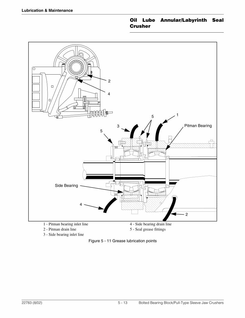
Oil Lube Annular/Labyrinth SealCrusher
Lubrication & Maintenance
1 - Pitman bearing inlet line 4 - Side bearing drain line2 - Pitman drain line 5 - Seal grease fittings3 - Side bearing inlet line
Figure 5 - 11 Grease lubrication points
2
3
4
Side Bearing
Pitman Bearing
1
2
4
5
5
22783 (8/02) 5 - 13 Bolted Bearing Block/Pull-Type Sleeve Jaw Crushers
Oil Lube Annular/Labyrinth SealCrusher
Lubrication & Maintenance
Periodic Lubrication
Lubricating oil should be changed every 1000hours of crusher operation or once each year,whichever occurs first.
1) The oil should be changed after the crusher has been run and the oil is at operating temperature.
2) Stop the crusher and clean area around drain plugs, fill plugs, and reservoir.
3) Drain the reservoir by removing the drain plug in the bottom of the reservoir. Since the oil in the bearing cavities drains by gravity back to the reservoir, draining the reservoir removes most of the oil from the crusher.
4) Remove the screen from suction strainer and clean it.
5) Reinstall the screen and drain plugs.
6) Add at least 10 gallons of flushing oil to the supply reservoir.
7) Run the crusher empty for at least 10 minutes.
8) Stop the crusher.
9) Drain the flushing oil from the reservoir. If it appears extremely dirty, repeat the flushing with fresh flushing oil to remove more of the contaminants until the drained flushing oil appears sufficiently clean.
10) Remove the screen from suction strainer once again and clean it.
11) Reinstall the screen.
12) Remove and replace the filter element.
13) Refill the reservoir with the appropriate oil listed in Table 5 - 2. Selecting the proper oil viscosity is critical to maintaining lubrication of the bearings. Thinner oils have less lubricating ability. Thicker oils may not flow freely at lower temperatures which could cause insufficient oil to be delivered to the bearings.
Regardless of which oil is used, the temperature of the oil returning from the bearings (operating temperature) must not exceed the Maximum Operating Temperature listed in Table 5 - 2.
Failure to use oil of proper viscositycould result in insufficient bearinglubrication. This could lead topremature bearing failure.
Do not allow the crusher to operatewhen the temperature of the oilreturning from the bearings exceedsthe temperature listed in Table 5 - 2.Failure to follow this warning couldcause premature bearing failure.
CAUTION
CAUTION
22783 (8/02) 5 - 14 Bolted Bearing Block/Pull-Type Sleeve Jaw Crushers

Oil Lube Annular/Labyrinth SealCrusher
Lubrication & Maintenance
BrandAmbient Temp
32°F (0°C) or aboveAmbient Temp
32°F (0°C) to 0°F (-18°C)Ambient Temp
below 0°F (--18°C)
Chevron Gear Compound EP 220 150
Exxon Spartan EP 220 150 68
Shell Omala EP 220 150 68
Mobil Mobilgear 630 629 68
Texaco Meropa 220 150 68
Maximum Operating Temperature (Returning from bearings)
190°F (88°C) 170°F (77°C) 130°F (54°C)
Table 5 - 2 Recommended oil viscosities/brands
22783 (8/02) 5 - 15 Bolted Bearing Block/Pull-Type Sleeve Jaw Crushers

Oil Lube Annular/Labyrinth SealCrusher
Lubrication & Maintenance
Oil Heater (optional)
For operation in cold weather, an optional oilheater system is available. Immersion heatersmounted in the tank maintain oil at athermostatically controlled temperature. Set thetemperature of the thermostat no higher than theMaximum Operating Temperature listed in Table5 - 2.
When using the oil heaters, the temperature of theoil returning from the bearings to the reservoirshould be monitored to ensure that the operatingtemperature does not exceed maximum operatingtemperature for the viscosity of oil being used. This
is especially important when using the lowerviscosity oils since their maximum operatingtemperature is low.
Do not heat oil by applying a torchflame directly to the reservoir.Extreme heating could burn the oiland reduce the oils ability tolubricate.
The optional oil heaters should be installedaccording to the schematic in Figure 5 - 12.
Figure 5 - 12 Oil heater electrical schematic
Cycle Timer (optional)
When operating in cold weather with the optionaloil heater system, an optional cycle timer can beused to warm the crusher and oil when notoperating. The cycle timer can be set to run thelubrication pump for short periods of time when thecrusher is not in operation. With the heaters
running, the warm oil in the reservoir will bepassed through the bearings and hoses to preventoil in these areas from gelling.
The cycle timer should be installed and wired asshown in the typical wiring schematic shown inFigure 5 - 13.
CAUTION
Heater #1
1000 W
Heater #2
1000 W
10430 Amp
120 VAC by customer30 Amp Service
100 102
104
104
105
106
Heater Power
ON
ON
OFF
OFF
22783 (8/02) 5 - 16 Bolted Bearing Block/Pull-Type Sleeve Jaw Crushers

Oil Lube Annular/Labyrinth SealCrusher
Lubrication & Maintenance
The timer can be set to cycle time from 0.6 secondsto 24 hours. By changing dip switch settings, thetime range of the timer dials is changed. The Offtimer controls the amount of time that the lubepump will shut off. The On timer controls thelength of time that the lube pump will be running.Setting the dip switches to the setting shown inFigure 5 - 13 will give the Off timer a range of 11-45 minutes. The On time will have a range of 1.5 -
5.5 minutes. Other time ranges can be selected bychanging the dip switch settings according to thechart on the side of the timer.
For normal operation the Day-Night switch shouldbe in the Day position which will allow the lubepump to run continuously when started. When theDay-Night switch is in the Night position the lubepump will run on the timed cycle set by the timerdials.
Figure 5 - 13 Lube pump cycle timer
Timer Dials
Timer Dip Switches
22783 (8/02) 5 - 17 Bolted Bearing Block/Pull-Type Sleeve Jaw Crushers

Periodic Maintenance
Lubrication & Maintenance
Periodic Maintenance
Maintenance Benchmark Checklist
The maintenance benchmark checklist can be auseful tool to determine if bearings or componentsare operating outside of normal operating ranges.Refer to Table 5 - 3. When the crusher is first putinto service and at operating temperature, recordthe following in the “Benchmark” column.
• Bearing Temperature
• Electrical Component Temperature
• Full Load Amps and Voltages
• Belt Tension
Each month the readings should be taken again andrecorded in the appropriate column. Alwaysremember to use the same measuring procedure. Ifa reading varies significantly from previous orbenchmark readings, investigate the cause.
22783 (8/02) 5 - 18 Bolted Bearing Block/Pull-Type Sleeve Jaw Crushers

Maintenance Benchmark CheckSheet
Lubrication & Maintenance
Maintenance Benchmark Check Sheet
Ben
chm
ark
Jan
uar
y
Feb
ruar
y
Mar
ch
Ap
ril
May
Jun
e
July
Au
gu
st
Sep
tem
ber
Oct
ob
er
Nov
emb
er
Dec
emb
er
I) Temperatures
A. Bearings
1. Drive Side
2. Non Drive Side
3. Drive Side Pitman
4. Non Drive Side Pitman
5. Jack Shaft/Outboard Bearing
B. Electrical Components
1. Starters
2. Breakers
3. Motor
4. Plug
II) Electrical Checks
A. Full Load Amps
1. At Motor
2. Below Starter
3. Top of Starter
4. Below Breaker
5. Above Breaker
B. Voltage (each leg)
1. L1
2. L2
3. L3
III) Belt Tension
A. Drive Belts
B. Oil Pump Drive
Table 5 - 3 Maintenance Benchmark Check Sheet
22783 (8/02) 5 - 19 Bolted Bearing Block/Pull-Type Sleeve Jaw Crushers
Maintenance Benchmark CheckSheet
Lubrication & Maintenance
Periodic Inspections
1) Check and tighten all fastening and mounting bolts, cap screws and set screws.
2) Inspect the stationary and movable jaws for wear. To maintain efficient operation the jaws should be turned when the corrugations at the lower end are worn almost smooth, or replaced after both ends are worn. The stationary jaw will generally require turning or replacing more often than the movable jaw.
Failure to replace jaws whencorrugations are worn smooth, orrunning crusher until concavesections are worn in jaws willreduce capacity of crusher. Also,jaws not changed whenrecommended will causecompaction of material in crushingchamber and could result inpremature bearing failure, excessivebreakage of toggle plates or shaft orbase breakage.
3) Inspect the key plates, especially the lower sections, for wear. Replace when worn through. Tighten both of the key plates.
4) Check and tighten the movable jaw wedge to prevent the movable jaw from becoming loose and causing wear or damage to the pitman.
5) The toggle plate needs no care other than lubrication and replacement when natural wear reduces the balls on both ends. When the balls have worn 1 inch (25.4 mm) on each end or half the original ball, replace toggle plate. Do this before excessive wear occurs to toggle seat insert in pitman and the base toggle seat. Be sure the toggle plate is located as centrally in position as possible in relation to the toggle seat insert in the pitman.
WARNING
22783 (8/02) 5 - 20 Bolted Bearing Block/Pull-Type Sleeve Jaw Crushers

Standard Drive Electrical
Electrical
Section 6 - Electrical
Standard Drive Electrical
No drive electrical controls are provided asstandard with the crusher. It is usually controlledfrom the main power panel. Check with thesupplier of the electrical system for specificinformation.
22783 (8/02) 6 - 1 Bolted Bearing Block/Pull-Type Sleeve Jaw Crushers
Standard Drive Electrical
Electrical
22783 (8/02) 6 - 2 Bolted Bearing Block/Pull-Type Sleeve Jaw Crushers

Troubleshooting
Troubleshooting
Section 7 - Troubleshooting
Troubleshooting
Crusher Not Operating At Rated Capacity
1) Pitman shaft direction of rotation incorrect.
2) Stationary jaw loose.
3) Speed incorrect.
4) Jaws excessively worn.
5) Attempting to feed raw material larger than crushing chamber.
6) Incorrect toggle plate for size of crusher discharge opening.
7) Lack of raw material or erratic feeding of crusher.
8) Insufficient power or v-belt slippage.
Bearings Overheating
The bearings normally operate at 100° to 150°F(38° to 66°C) but in warm climates may reach 180°to 200°F (82° to 93°C). Under these conditions andwithin these limits the bearings are notoverheating. However, if a bearing maintains212°F (100°C) or higher, it is considered to beoverheating. The cause should be found andcorrected.
Temperature should be checked on housing closestto the bearing or on the end plate nearest thebearing.
The following are some of the most commoncauses of bearing overheating:
1) Improper lubricant level. Too much lubricant will not allow for proper circulation and air space inside housing. Fill only to correct levels.
2) Insufficient, dirty or improper lubricant.
3) Operating at a speed faster than recommended.
4) Crusher out of level. This will cause lubricant to flow away from the high bearing. Make sure crusher is level.
5) Side bearing outer seal and flinger not turning with shaft.
6) Insufficient radial clearance between side bearing outer seal and end cap.
7) Toggle plate improperly seated.
8) Bearing(s) damaged and/or failing.
9) Movable jaw rubbing on base or key plates.
10) Bent pitman shaft.
11) Seals Rubbing.
22783 (8/02) 7 - 1 Bolted Bearing Block/Pull-Type Sleeve Jaw Crushers

Troubleshooting
Troubleshooting
Excessive Jaw Wear
1) Stationary jaw loose.
2) Closing crusher below minimum recommended discharge opening.
3) Operating faster than recommended.
4) Not using genuine Cedarapids jaws.
5) Very abrasive material.
Difficult to Adjust Closed Side Setting
1) Tension spring not released.
2) Support angles on base not loose.
3) Toggle seat loose and “peened” into base.
22783 (8/02) 7 - 2 Bolted Bearing Block/Pull-Type Sleeve Jaw Crushers
Torque Charts
Torque Specs
Appendix A - Torque Specs
Torque Charts
The following pages contain charts for use asguides when tightening bolts and nuts. Thesespecifications should be followed unless specifictorques are given elsewhere in this manual.
Standard Torque Chart
Table A - 1 is a list of recommended torque valuesfor standard bolts. Use this torque chart to avoidoverstressing standard nuts and bolts used on theequipment. These specifications should befollowed unless specific torques are given. Theequipment uses Grades 2, 5, and 8. The maximumtorque values are based on 75% of the specifiedminimum proof strength of the bolt steel in order toprovide a safety factor. The term “lube” applies tocadmium plating and/or application of threadlubricants. Hardened washers should always beused, regardless of whether standard nuts or locknuts are employed.
Metric Torque Chart
Table A - 2 is a list of torque values recommendedfor metric bolts. The maximum torque values arebased on 75% of the specified minimum proofstrength. The term “lube” includes the applicationof thread lubricants, cadmium plating and the useof hardened washers regardless of whetherstandard or lock nuts are used.
22783 (8/02) A - 1 Bolted Bearing Block/Pull-Type Sleeve Jaw Crushers

Torque Charts
Torque Specs
Standard Torque Chart
S.A.E Grade 2 S.A.E Grade 5 S.A.E Grade 8
dia. (inches)
pitch(thread/in.)
Torque (ft-lbs)Clamp
Load (lbs)
Torque (ft-lbs)Clamp
Load (lbs)
Torque (ft-lbs) ClampLoad (lbs)Dry Lube Dry Lube Dry Lube
1/4 20 5 4 1310 8 6 2020 12 9 2860
1/4 28 6 5 1500 10 7 2320 14 11 3270
5/16 18 11 9 2160 17 13 3340 25 19 4710
5/16 24 12 10 2390 19 15 3690 27 21 5220
3/8 16 20 15 3190 31 24 4940 44 34 6970
3/8 24 23 17 3620 35 27 5590 49 38 7900
7/16 14 32 25 4380 49 38 6770 70 54 9560
7/16 20 36 27 4890 55 42 7560 78 60 10680
1/2 13 49 38 5850 75 58 9040 106 82 12770
1/2 20 55 42 6590 85 65 10190 120 92 14390
9/16 12 70 54 7500 109 84 11600 150 115 16380
9/16 18 79 60 8370 121 93 12940 170 130 18270
5/8 11 97 75 9320 150 115 14400 210 160 20340
5/8 18 110 85 10560 170 130 16320 240 180 23040
3/4 10 170 130 13770 265 200 21290 375 285 30060
3/4 16 190 145 15380 295 225 23770 415 320 33570
7/8 9 165 125 11430 425 330 29450 605 465 41580
7/8 14 180 140 12590 470 360 32440 665 510 45810
1 8 245 190 14990 640 495 38630 905 695 54540
1 14 270 210 16400 700 540 42260 990 765 59670
1-1/8 7 350 270 18880 790 610 42340 1285 990 68670
1-1/8 12 395 305 21180 890 685 47500 1440 1110 77040
1-1/4 7 495 380 23980 1120 860 53770 1815 1395 87210
1-1/4 12 550 425 26550 1240 950 59550 2010 1545 96570
1-3/8 6 655 500 28580 1465 1130 64100 2380 1830 103950
1-3/8 12 745 570 32540 1670 1285 72980 2710 2085 118350
1-1/2 6 865 665 34770 1945 1495 77970 3160 2430 126450
1-1/2 12 975 750 39120 2190 1685 87740 3555 2735 142290
1-3/4 5 1370 1055 47020 2285 1755 78370 4985 3835 170990
2 4.5 2060 1585 61870 3435 2640 103120 7500 5765 225000
2-1/4 4.5 3015 2320 80430 5025 3865 134060 10960 8435 292500
2-1/2 4 4125 3170 99000 6875 5285 165000 15000 11530 360000
2-3/4 4 5590 4300 122010 9320 7165 203360 17790 13680 388230
3 4 7385 5680 147750 12310 9470 246260 23500 18080 470130
Table A - 1: Torque Values for Standard Hardware
22783 (8/02) A - 2 Bolted Bearing Block/Pull-Type Sleeve Jaw Crushers

Torque Charts
Torque Specs
Metric Torque Chart Property Class = 8.8 Property Class = 10.9 Property Class = 12.9
dia (mm)
pitch (mm)
Dry Lube Dry Lube Dry Lube
(ft-lbs) N-M (ft-lbs) N-M (ft-lbs) N-M (ft-lbs) N-M (ft-lbs) N-M (ft-lbs) N-M
10 1.5 37 50 29 39 53 72 41 56 62 84 48 65
10 1.25 39 53 30 41 56 76 43 58 66 89 51 69
12 1.75 65 88 50 68 93 126 71 96 109 148 83 113
12 1.25 71 96 55 75 101 137 78 106 119 161 91 123
14 2 104 141 80 108 148 201 114 155 173 235 133 180
14 1.5 112 152 86 117 160 217 123 167 187 254 144 195
16 2 161 218 124 168 230 312 177 240 269 365 207 280
16 1.5 172 233 132 179 246 334 189 256 287 389 221 300
18 2.50 230 312 177 240 318 431 245 332 372 504 286 388
18 1.5 258 350 199 270 357 484 275 348 418 567 321 435
20 2.5 325 441 250 339 450 610 346 469 525 712 404 548
20 1.5 360 488 277 376 499 677 384 521 583 791 448 607
22 2.5 443 601 341 462 613 831 471 639 716 971 551 747
22 1.5 486 659 374 507 673 913 518 702 786 1066 605 820
24 3 562 762 432 586 777 1054 598 811 908 1231 698 946
24 2 612 830 471 639 847 1149 652 884 990 1342 762 1033
27 3 823 1116 633 858 1139 1544 876 1188 1331 1805 1024 1389
27 2 889 1205 683 926 1229 1667 945 1281 1436 1947 1105 1498
Table A - 2: Torque Values for Metric Hardware
22783 (8/02) A - 3 Bolted Bearing Block/Pull-Type Sleeve Jaw Crushers

Torque Charts
Torque Specs
22783 (8/02) A - 4 Bolted Bearing Block/Pull-Type Sleeve Jaw Crushers

General Belt Information
General Belt Drive Care
Appendix B - General Belt Drive Care
General Belt Information
You get more service from V-belts if you keepthem clean and dry. Rock dust and rust from metalsare abrasive. Oils and acids deteriorate beltmaterial. Dust buildup in sheaves causes harmfulvibration. On belts, dust or water causes slippage.
For maintenance purposes, so-called belt dressingcompounds are worse than worthless. Most beltdressings actually shorten belt life. Clean, wellcared for belts are the best answer to problems thatbelt dressings are meant for but do not solve. Dailycleaning of belts and sheaves by blowing them offwith compressed air increases their useful life andsaves you money.
1) Keep belts and sheaves clean.
2) Avoid belt or sheave rubbing. Don't let belts orsheaves rub against the guard (or anything else)while they’re running.
3) Drive your belts with motors mounted onadjustable bases.
Mount drive motors on a slotted base, so you canshorten the distance from motor to driven sheavewhen you need to do so. This allows convenientand proper installation of belts. Prying on beltswith tools cracks and prematurely breaks them.With belts already lightly seated in their grooves,you can tighten the belts correctly by moving themotor and rolling the sheaves at the same time.
4) Keep belts tight.
Most belt stretch occurs in the first 30-40 hours ofoperation after new belts are installed. Check belttension frequently during this period. Slack beltscause slipping and excessive wear. They cost youmoney by delivering less power and causing morefrequent replacement.
5) Periodically inspect the V-belt drive for wear(Figure B - 2) and for proper sheave alignment(Figure B - 1).
6) Do not overtighten belts.
Overtightening shortens useful life of belts andsheaves and also places undue strain on shaftswhich, in turn, causes premature bearing failure.Ideal belt tension is lowest at which belts won't slipunder peak load.
Figure B - 1: Align Sheaves
7) Keep belts straight (Figure B - 1).
Don't allow V-belts to run out of alignment. To runproperly, sheaves must be parallel and groovesmust be in line.
8) Use only matched belts. A matched set of beltslasts longer because loading is evenly dividedamong all the belts.
OK
OK
22783 (8/02) B - 1 Bolted Bearing Block/Pull-Type Sleeve Jaw Crushers

Maintaining V-Belt Tension
General Belt Drive Care
Belts often wear at the sides, so their cross-sectional area decreases. They stretch with use andage. New belts ride higher in sheave grooves. Theytravel faster and take higher tension than wornbelts. If its center cord breaks, a belt stretches andwon't carry its load. Putting one or two new belts ona partially used set very soon wears and stretchesthe new ones until they are in poor condition. Theircost is wasted.
Belts from different manufacturers should not bemixed in a set because of slight material and qualitydifferences that could reduce the life of all thebelts. Always replace belts in full sets.
9) Don't overload.
If the sheave has 10 grooves, use 10 belts. Usingless than the designed number of drive belts putstoo much strain on remaining ones. They will breakdown quickly and cause you downtime.
10) Replace worn sheaves.
Worn sheaves reduce belt life. If the sheave is wornenough that belts touch bottom in the grooves, beltssoon start to slip and burn.
If your maintenance program takes all of thosethings into account, your troubles with belts andsheaves will be minimal. Still, you’re bound toexperience some problem, sooner or later. Whenyou do, use Table B - 1 as a diagnostic tool.
Maintaining V-Belt Tension
1) Check drive belt tension daily. Check conditionof belts and sheaves (Figure B - 2).
2) If belts are worn, replace with a matched set.
3) Use a sheave gauge (Figure B - 3) to look forsteps worn in sheave grooves. Steps are ameasure of sheave wear. Belts must not bottomout in grooves.
4) If sheaves are worn excessively, replace them.
5) If belts are not tight enough, loosen drive motormount bolts and adjust take-up bolts to tightenbelts. Retighten motor mount bolts to holdtension.
Figure B - 2: Belt & Sheave Wear
Figure B - 3: Sheave Gauge Shows Wear
Worn Sheave Worn Belt or Sheave
Just Right
22783 (8/02) B - 2 Bolted Bearing Block/Pull-Type Sleeve Jaw Crushers

Maintaining V-Belt Tension
General Belt Drive Care
Table B - 1: Belt-Drive Diagnostics
Trouble Cause Correction
Belts slip (sidewalls glazed) Insufficient tension Replace belts; increase tension
Drive squeals.Overloaded drive.Arc of contact too short.Heavy starting load.
Find cause and correct.Increase distance between hubs.Increase tension.
Belt rolls over.
Rock gets into drive.Broken cord caused by prying.Overloaded drive.Impulse Loads.
Misalignment.Worn sheave grooves.Flat idler sheave.
Excessive vibration.
Replace belt correctly.Redesign drive.Apply proper tension.
Realign drive.Replace sheave.Align and reposition.
Check drive design, mounting.Consider banded belts.
Mismatched belts
New belts installed with old.
Sheave grooves worn unevenly. Improper groove angle.
Shafts not parallel.
Replace belts with matched set.
Replace sheaves.
Align drive.
Belt breaks
Shock loads.
Heavy starting load.
Belt pried over sheaves.Foreign object in drive.
Apply proper tension.
Apply proper tension.Use compensator starting.
Replace belt correctly.Determine source of object, design guard to correct problem.
Belt wears prematurely.
Sheave grooves worn.Sheave diameter too small.Mismatched belts.Drive overloaded.Belt slips.Sheaves misaligned.Oil present.Excess heat present.
Replace sheaves.Redesign drive.Replace with matched set.Redesign drive.Increase tension.Align sheaves.Eliminate oil.Ventilate drive.
22783 (8/02) B - 3 Bolted Bearing Block/Pull-Type Sleeve Jaw Crushers

Check Belt Tension with Mechani-cal Tester
General Belt Drive Care
Figure B - 4: Belt Tension Tester (Cedarapids P/N 45500-036-08)
Figure B - 5: Using the Belt Tension Tester
Check Belt Tensionwith Mechanical Tester
1) Measure span length "T" (Figure B - 5).
2) Position large O-ring on tester at 1/64 inch(0.397 mm) for each inch of belt span. Set smallO-ring at zero (Figure B - 5). Example: For beltspan of 48 inches (1.219 m), setting would be48/64 inch (3/4 inch, or 19.05 mm).
3) At center of belt span, push yellow tippedplunger until bottom of large O-ring is levelwith top of adjacent belt (Figure B - 5). If thereis no adjacent belt, lay straight edge betweensheaves for reference.
4) Remove tester and read belt deflection force, inpounds, at small O-ring. Compare this figurewith values given in tables that follow. Ifrequired force is within limits shown in tablefor that particular belt, drive tension should besatisfactory. If required force is outside theselimits, drive should be retensioned.
5) When installing new belts, tension may relieveduring run-in. After drive is operated forseveral days, tension should be checked andadjusted to recommended tension values.
Each 1/64" mark equals 1" of belt span(Centimeters on Opposite Side)
Each Mark Equals 1 Pound Pressure(Kilograms on Opposite Side)
Large O-ring Small O-ring
Bottom ofStraightedge or Top of
Adjacent Belt
Small O-ring
Large O-ringDeflection to be 1/64"
Per Inch Span
Span "t"
22783 (8/02) B - 4 Bolted Bearing Block/Pull-Type Sleeve Jaw Crushers
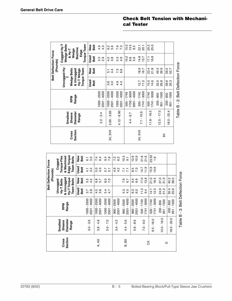
Check Belt Tension with Mechani-cal Tester
General Belt Drive Care
Tab
le B
- 2
: Bel
t Def
lect
ion
For
ce
Cro
ssS
ecti
on
Sm
alle
stS
hea
veD
iam
eter
Ran
ge
RP
MR
ang
e
Bel
t D
efle
ctio
n F
orc
e(P
ou
nd
s)
Un
cog
ged
Hy-
TW
edg
e B
elts
& U
nco
gg
edH
y-T
Wed
ge
Torq
ue
Team
Co
gg
ed H
y-T
Wed
ge
Bel
ts&
Hy-
T
Wed
ge
Mac
hin
e E
dg
eTo
rqu
e Te
am
Use
dB
elt
New
Bel
tU
sed
Bel
tN
ewB
elt
3V, 3
VX
2.2
- 2.
410
00 -
250
025
01 -
400
03.
32.
94.
94.
3
2.65
- 3
.65
1000
- 2
500
2501
- 4
000
3.6
3.0
5.1
4.4
4.2
3.8
6.2
5.6
4.12
- 6
.90
1000
- 2
500
2501
- 4
000
4.9
4.4
7.3
6.6
5.3
4.9
7.9
7.3
5V, 5
VX
4.4
- 6.
750
0 -
1749
1750
- 3
000
3001
- 4
000
10.2
8.8
5.6
15.2
13.2
8.5
7.1
- 10
.950
0 -
1740
1741
- 3
000
12.7
11.2
18.9
16.7
14.8
13.7
22.1
20.1
11.8
- 1
6.0
500
- 17
4017
41 -
300
015
.514
.623
.421
.817
.116
.825
.525
.0
8V
12.5
- 1
7.0
200
- 85
085
1 -
1500
33.0
26.8
49.3
39.9
18.0
- 2
2.4
200
- 85
085
1 -
1500
39.6
35.3
59.2
52.7
Tab
le B
- 3
: Bel
t Def
lect
ion
For
ce
Cro
ss
Sec
tio
n
Sm
alle
stS
hea
veD
iam
eter
Ran
ge
RP
MR
ang
e
Bel
t D
efle
ctio
n F
orc
e(P
ou
nd
s)
Un
cog
ged
Hy-
T B
elts
& U
nco
gg
edH
y-T
To
rqu
e Te
am B
elts
Co
gg
edTo
rqu
e-F
lex
& M
ach
ined
Ed
ge
Torq
ue
Team
Bel
ts
Use
dB
elt
New
Bel
tU
sed
Bel
tN
ewB
elt
A, A
X
3.0
- 3.
610
00 -
250
025
01 -
400
03.
72.
85.
54.
24.
13.
46.
15.
0
3.8
- 4.
810
00 -
250
025
01 -
400
04.
53.
86.
85.
75.
04.
37.
46.
4
5.0
- 7.
010
00 -
250
025
01 -
400
05.
44.
78.
07.
05.
75.
19.
47.
6
B, B
X
3.4
- 4.
286
0 -
2500
2501
- 4
000
4.9
4.2
7.2
6.2
4.4
- 5.
686
0 -
2500
2501
- 4
000
5.3
4.5
7.9
6.7
7.1
7.1
10.5
9.1
5.8
- 8.
686
0 -
2500
2501
- 4
000
6.3
6.0
9.4
8.9
8.5
7.3
12.6
10.9
CX
7.0
- 9.
050
0 -
1740
1741
- 3
000
11.5
9.4
17.0
13.8
14.7
11.9
21.8
21.6
9.5
- 16
.050
0 -
1740
1741
- 3
000
14.1
12.5
21.0
18.5
15.9
14.6
23.5
21.
6
D
12.0
- 1
6.0
200
- 85
085
1 -
1500
24.9
21.2
37.0
31.3
18.0
- 2
0.0
200
- 85
085
1 -
1500
30.4
25.6
45.2
38.0
22783 (8/02) B - 5 Bolted Bearing Block/Pull-Type Sleeve Jaw Crushers
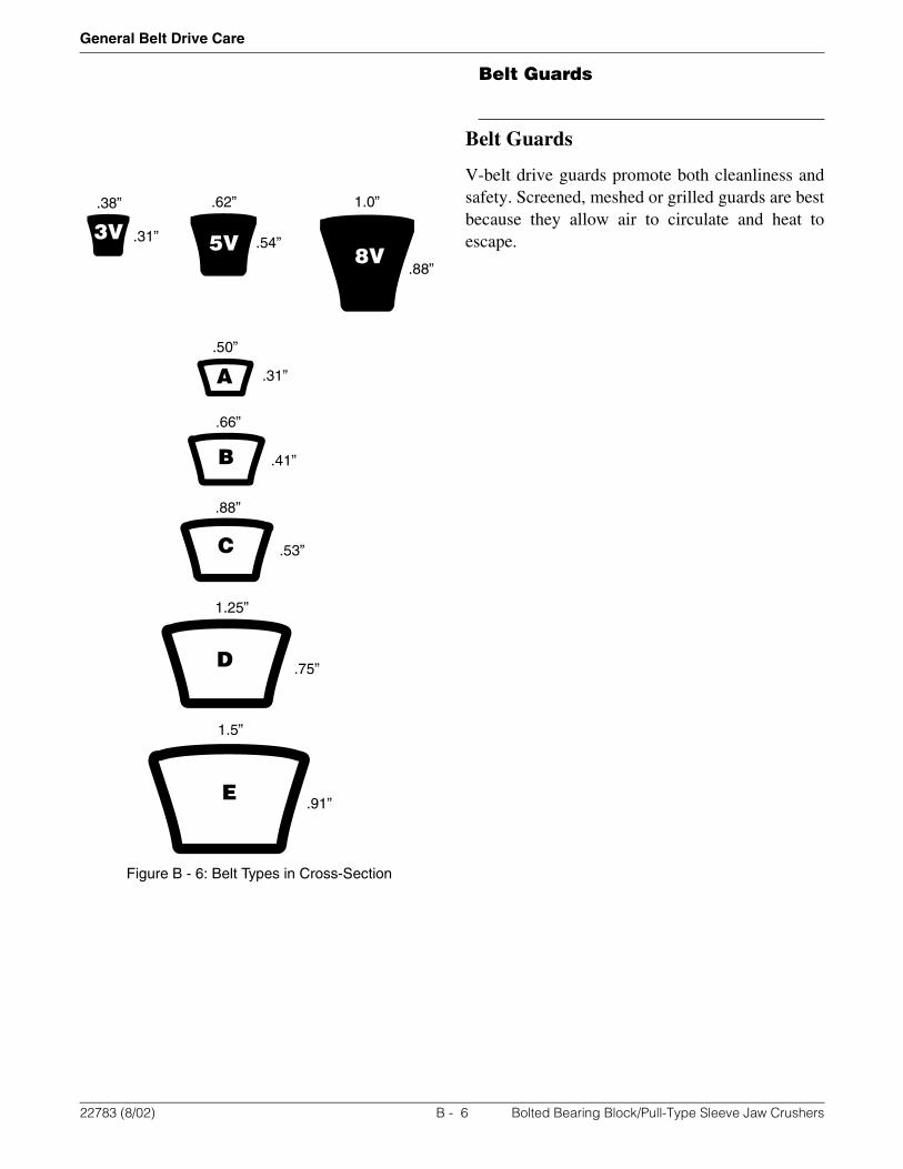
Belt Guards
General Belt Drive Care
Figure B - 6: Belt Types in Cross-Section
Belt Guards
V-belt drive guards promote both cleanliness andsafety. Screened, meshed or grilled guards are bestbecause they allow air to circulate and heat toescape.
8V5V3V
A
B
C
D
E
1.0”.62”.38”
.88”
.54”.31”
.50”
.31”
.66”
.41”
.88”
.53”
1.25”
.75”
1.5”
.91”
22783 (8/02) B - 6 Bolted Bearing Block/Pull-Type Sleeve Jaw Crushers

Idlers
General Belt Drive Care
Idlers
A properly designed V-belt drive does not requirean idler to deliver full rated horsepower if properbelt tension can be maintained. Idlers should beavoided if possible because an idler puts anadditional bending stress point on the belt. Thisreduces the belt’s horsepower rating and its lifeexpectancy. The smaller the idler, the greater thestress and the more belt life is reduced.
Inside Idler
A V-grooved idler located on the inside of the beltson the slack side of the drive is recommended overa back-side idler. The idler should be located nearthe large sheave to minimize reduction of the arc ofcontact across the small sheave. The diameter ofthe V-idler pulley should be equal to or larger thanthat of the small sheave.
Back-Side Idler
A back-side idler increases the arc of contact onboth sheaves. However, it forces a backward bendin the V-belt that contributes to premature beltfailure. The idler puts additional stress on thebottom portion of the belt which will result inbottom cracking. If a back-side idler must be used,the diameter of the flat idler pulley should be atleast 1-1/2 times (1.5x) the diameter of the smallsheave. A back-side idler should be located as closeas possible to the small sheave.
Kiss Idler
A kiss idler differs from the back-side idler becausethe kiss idler does not penetrate the belt span andcreate a back-bend on the belt. Consequently, thekiss idler does not contribute to premature beltfailure.
Use of a kiss idler can help control belt vibrationand whip on drives subject to shock and pulsatingloads. Kiss idlers can be used in single-belt driveswhere joined belts are not applicable.
If a kiss idler is used, diameter of the flat pulleyshould be at least 1-1/2 times (1.5x) greater thanthe diameter of the small sheave.Driver
Driven
Driver
Driven
Driver
Driven
22783 (8/02) B - 7 Bolted Bearing Block/Pull-Type Sleeve Jaw Crushers
Idlers
General Belt Drive Care
NOTES:
22783 (8/02) B - 8 Bolted Bearing Block/Pull-Type Sleeve Jaw Crushers