![DIAL: A Distributed Adaptive-Learning Routing Method in VDTNscs.virginia.edu/~hs6ms/publishedPaper/Conference/2016/... · 2016-04-21 · [1] T. Henderson, etc. “The changing usage](https://static.fdocuments.us/doc/165x107/5f7bfe18ed3c330fdd019a1f/dial-a-distributed-adaptive-learning-routing-method-in-hs6mspublishedpaperconference2016.jpg)
CEDAR: A Low-latency and Distributed Strategy for...
9
CEDAR: A Low-latency and Distributed Strategy for Packet Recovery in Wireless Network Chenxi Qiu*, Haiying Shen*, Sohraab Soltani † , Karan Sapra*, Hao Jiang ? and Jason Hallstrom ? *Department of Electrical and Computer Engineering, Clemson University, Clemson, SC 29634, USA ? School of Computing, Clemson University, Clemson, SC 29634, USA † Intelligent Automation, Inc., Rockville, MD 20855, USA Abstract—Underlying link-layer protocols of wireless net- works use the conventional “store and forward” design paradigm cannot provide highly sustainable reliability and stability in wireless communication, which introduce significant barriers and setbacks in scalability and deployments of wireless networks. In this paper, we propose a Code Embedded Dis- tributed Adaptive and Reliable (CEDAR) link-layer framework that targets low latency and high throughput. CEDAR is the first comprehensive theoretical framework for analyzing and designing distributed and adaptive error recovery for wireless networks. It employs a theoretically-sound framework for embedding channel codes in each packet and performs the error correcting process in selected intermediate nodes in packet’s route. To identify the intermediate nodes for the en/decoding for minimizing average packet latency, we mathematically analyze the average packet delay, using Finite State Markovian Channel model and priority queuing model, and then formalize the problem as a non-linear integer programming problem. Also, we propose a scalable and distributed scheme to solve this problem. The results from real-world testbed “NESTbed” and simulation with Matlab prove that CEDAR is superior to the schemes using hop-by-hop decoding and destination-decoding not only in packet delay but also in throughput. In addition, the simulation results show that CEDAR can achieve the optimal performance in most cases. I. I NTRODUCTION Despite the unprecedented success and proliferation of wireless communication, there are major shortcomings in the underlying link-layer protocols in providing sustainable reliability and stability among wireless users. Popular wire- less link-layer protocols, such as the retransmission ARQ or Forward Error Correction (FEC) based ARQ (HARQ) approaches (employed by the IEEE 802.xx and LTE standard suite) are designed to achieve some level of reliability by dis- carding a corrupted packet at the receiver and performing one or more retransmissions until the packet is decoded/received error-free or a maximum number of retransmission attempts is reached. This methodology suffers from degradation of throughput and overall system instability since decoding failures at the receiver due to a small number of bit errors lead to packet drops and discarding a large number of correctly delivered data bits. Many leading research efforts [1]–[11] have highlighted the inefficiencies of these link-layer protocols and proposed a variety of remedy solutions. The majority of these efforts either consider variations of the ARQ, HARQ or a hybrid approach of both schemes [1], [5], [11], [12]. They largely follow the traditional “store-and-forward” link-layer design paradigm: each data packet must be fully received and corrected by every relay node before it is forwarded. This design paradigm increases stability but still cannot provide high stability due to its hop-by-hop operation. It is our belief that achieving the ultimate objective of the development of ubiquitous and heterogeneous wireless networks demands fundamental and radical changes to the conventional link-layer protocol design. Thus, we study and develop alternative optimal and low-complexity error recovery strategies in link-layer design to achieve high reliability and stability by partially and optimally selecting relay nodes. The objectives of the strategies are to ensure, (1) Low end-to-end latency and rapid delivery of packets; (2) High throughput with minimum data loss. To meet these objectives, we develop solutions that address the following key issues: (1) Minimizing propagation and transmission (prop&tran) delay: at which intermediate nodes (if any) a link-layer packet should be detected to minimize packet delay? (2) Minimizing queuing delay: as multiple relay nodes in a route perform error recovery on the same packet stream and one node may perform error recovery for multiple packet streams, how to select relay nodes that provides global reliability and stability in a wireless network with many source-destination packet streams? As a solution, we develop mathematical models for the prop&tran delay and queuing delay for a packet based on the path length between two consecutive decoding nodes in a route (route segment length). Through rigorous mathematical analysis on the models, we derive two propositions that (1) can identify the intermediate nodes for decoding which minimize prop&tran delay of a packet, and (2) prove that bal- anced en/decoding load distribution among decoding nodes in the network minimizes the queuing delay. Based on the propositions, we formulate the problem of minimizing delay as a non-linear integer programming problem. However, due to the NP-hard nature of the problem and impracticability of collecting all required information to find the global optimal solution, we propose a sub-optimal Code Embed- ded Distributed Adaptive and Reliable (CEDAR) link-layer framework for wireless networks. CEDAR is a distributed and cooperative error recovery design, which provides an adaptive environment for various error recovery strategies with respect to reliability and stability. We summarize our contributions as follows: (1) We build a model for the probability of decoding failure of a packet traveling through a given number of hops based on the Finite State Markovian Channel (FSMC) model; (2) We build rigid mathematical models for the prop&tran delay, and queuing delay for a packet; (3) We formalize the problem of choosing the intermediate en/decoing nodes for minimum delay as a non-
Transcript of CEDAR: A Low-latency and Distributed Strategy for...
CEDAR: A Low-latency and Distributed Strategy for PacketRecovery in Wireless Network
Chenxi Qiu*, Haiying Shen*, Sohraab Soltani†, Karan Sapra*, Hao Jiang? and Jason Hallstrom?
*Department of Electrical and Computer Engineering, Clemson University, Clemson, SC 29634, USA?School of Computing, Clemson University, Clemson, SC 29634, USA
†Intelligent Automation, Inc., Rockville, MD 20855, USA
Abstract—Underlying link-layer protocols of wireless net-works use the conventional “store and forward” designparadigm cannot provide highly sustainable reliability andstability in wireless communication, which introduce significantbarriers and setbacks in scalability and deployments of wirelessnetworks. In this paper, we propose a Code Embedded Dis-tributed Adaptive and Reliable (CEDAR) link-layer frameworkthat targets low latency and high throughput. CEDAR is thefirst comprehensive theoretical framework for analyzing anddesigning distributed and adaptive error recovery for wirelessnetworks. It employs a theoretically-sound framework forembedding channel codes in each packet and performs the errorcorrecting process in selected intermediate nodes in packet’sroute. To identify the intermediate nodes for the en/decoding forminimizing average packet latency, we mathematically analyzethe average packet delay, using Finite State Markovian Channelmodel and priority queuing model, and then formalize theproblem as a non-linear integer programming problem. Also,we propose a scalable and distributed scheme to solve thisproblem. The results from real-world testbed “NESTbed” andsimulation with Matlab prove that CEDAR is superior to theschemes using hop-by-hop decoding and destination-decodingnot only in packet delay but also in throughput. In addition, thesimulation results show that CEDAR can achieve the optimalperformance in most cases.
I. INTRODUCTION
Despite the unprecedented success and proliferation ofwireless communication, there are major shortcomings inthe underlying link-layer protocols in providing sustainablereliability and stability among wireless users. Popular wire-less link-layer protocols, such as the retransmission ARQor Forward Error Correction (FEC) based ARQ (HARQ)approaches (employed by the IEEE 802.xx and LTE standardsuite) are designed to achieve some level of reliability by dis-carding a corrupted packet at the receiver and performing oneor more retransmissions until the packet is decoded/receivederror-free or a maximum number of retransmission attemptsis reached. This methodology suffers from degradation ofthroughput and overall system instability since decodingfailures at the receiver due to a small number of bit errorslead to packet drops and discarding a large number ofcorrectly delivered data bits.
Many leading research efforts [1]–[11] have highlightedthe inefficiencies of these link-layer protocols and proposeda variety of remedy solutions. The majority of these effortseither consider variations of the ARQ, HARQ or a hybridapproach of both schemes [1], [5], [11], [12]. They largelyfollow the traditional “store-and-forward” link-layer designparadigm: each data packet must be fully received andcorrected by every relay node before it is forwarded. This
design paradigm increases stability but still cannot providehigh stability due to its hop-by-hop operation.
It is our belief that achieving the ultimate objective ofthe development of ubiquitous and heterogeneous wirelessnetworks demands fundamental and radical changes to theconventional link-layer protocol design. Thus, we studyand develop alternative optimal and low-complexity errorrecovery strategies in link-layer design to achieve highreliability and stability by partially and optimally selectingrelay nodes. The objectives of the strategies are to ensure,(1) Low end-to-end latency and rapid delivery of packets;(2) High throughput with minimum data loss. To meet theseobjectives, we develop solutions that address the followingkey issues: (1) Minimizing propagation and transmission(prop&tran) delay: at which intermediate nodes (if any)a link-layer packet should be detected to minimize packetdelay? (2) Minimizing queuing delay: as multiple relay nodesin a route perform error recovery on the same packet streamand one node may perform error recovery for multiple packetstreams, how to select relay nodes that provides globalreliability and stability in a wireless network with manysource-destination packet streams?
As a solution, we develop mathematical models for theprop&tran delay and queuing delay for a packet based onthe path length between two consecutive decoding nodes in aroute (route segment length). Through rigorous mathematicalanalysis on the models, we derive two propositions that(1) can identify the intermediate nodes for decoding whichminimize prop&tran delay of a packet, and (2) prove that bal-anced en/decoding load distribution among decoding nodesin the network minimizes the queuing delay. Based on thepropositions, we formulate the problem of minimizing delayas a non-linear integer programming problem. However, dueto the NP-hard nature of the problem and impracticabilityof collecting all required information to find the globaloptimal solution, we propose a sub-optimal Code Embed-ded Distributed Adaptive and Reliable (CEDAR) link-layerframework for wireless networks. CEDAR is a distributedand cooperative error recovery design, which provides anadaptive environment for various error recovery strategieswith respect to reliability and stability. We summarize ourcontributions as follows: (1) We build a model for theprobability of decoding failure of a packet traveling througha given number of hops based on the Finite State MarkovianChannel (FSMC) model; (2) We build rigid mathematicalmodels for the prop&tran delay, and queuing delay fora packet; (3) We formalize the problem of choosing theintermediate en/decoing nodes for minimum delay as a non-

Fig. 1. Protocols for packet recovery.
linear integer programming problem which is an NP-hardproblem; (4) We propose a distributed sub-optimal strategyfor CEDAR that achieves high reliability and stability.
The reminder of the paper is organized as follows. SectionII states the problem that needs to be solved to minimize thepacket delay. Section III introduces mathematical model thatformalizes the problem as a non-linear integer programmingproblem and derives two propositions to minimize the delay.Guided by the propositions, Section IV details the design ofCEDAR for solving the problem in Section II, and Section Vpresents performance evaluation of CEDAR in comparisonwith previous schemes. Section VI presents a review of therelated works. The final section concludes with a summaryof contributions and a discussion on future research work.
II. PROBLEM STATEMENT
Consider a wireless network comprised of N nodes rep-resented as V = {v1, v2, ..., vN}. Each traffic flow froma source node to a destination node transverses over apredetermined set of links (a route specified by the networklayer). Let R = {r1, r2, ..., rB} denote the transmissionroutes. Each route rk (1 ≤ k ≤ B) carries a data streamfollowing Poisson distribution with arrival rate λk. A vectorof nodes rk = {vk0 , vk1 , ..., vknk
} (vk0 , vk1 , ..., vknk∈ V)
represents the nodes in rk, where nk = |rk| .As shown in Fig. 1, to reach the destination, each packet
flow needs to travel through all nodes in the predeter-mined route, and some of these nodes are responsible foren/decoding the packets. In the ARQ and HARQ protocols[1], [5], [11], each hop drops distorted packets and requestsfor complete or partial retransmission of the original packets.Though these methods guarantee the reliability between anypair of nodes, they cause high delays and low throughputdue to numerous retransmissions at every hop. CEDAR intro-duces a new flexible environment for link-layer error recov-ery: the error correction process is performed in a distributedmanner where selected (and not all) intermediate nodesparticipate in performing error recovery. The key problem inCEDAR is how to identify candidates among the intermedi-ate nodes for the en/decoding process to optimally decreaselatency and increase throughput over the entire network.
First, we build a model to calculate the prop&tran delay(Di
p&t (n′i)), and a model to calculate the queuing delay(Dq (n′i)) based on the lengths of the routing paths (n′i)of the packets crossing an intermediate node vi. We usethese models to minimize the expected delays and ultimatelyidentify the positions of intermediate nodes for en/decodingin each route in CEDAR. Throughout the paper, we use thekey terms provided in the following definitions:
Definition 1 (Key node): A key node of route rk is a noderesponsible for en/decoding the packets traveling along rk.Matrix X = (xi,k)N×B denotes whether vi is a key node in
rk:xi,k =
{1, vi is the key node in rk;0, vi is not the key node in rk.
(1)
Definition 2 (Route segment): A route segment of rk isa section of the end-to-end path between one key node toeither the endpoints or another key node.
In each route segment, the packet sender (the first keynode) encodes the packets and the packet receiver (thesecond key node) decodes the packets. In other words, thesecond key node is responsible for decoding for its routesegment. Use n′i,k to denote the number of hops in a routesegment with decoding node vi in rk. Let n′i denote thegroup of the lengths of route segments responsible by vi,i.e., n′i = {n′i,1, n′i,2, ..., n′i,B}. n′i,k = 0 if vi has noresponsibility of decoding the packet in rk. Let λ′i,k denotethe arrival rate of the data stream that vi is responsible foren/decoding in rk. Then λ′i,k = λk×xi,k. We use D (n′i) todenote the total average delay when one packet crosses viand use 0-1 variable fi,k to denote whether vi is in rk. Ifyes, fi,k = 1; otherwise fi,k = 0.
Objective. The objective of CEDAR is to minimize thetotal delay of the packets in the entire system, which can berepresented as:
min
N∑i=1
(D (n′i)
B∑k=1
λ′i,k
)s.t. xi,k ≤ fi,k (2)
The packet delay in vi (which is composed of prop&tran andqueueing delays) is a function of n′i. This will be deduced inthe mathematical analysis in Section III. We use Dp&t (n′i) todenote the average prop&tran delay of all the packet streamsbeing decoded in vi, and use Dq (n′i) to denote the averagequeuing delay of the packet stream in vi. Then, the totalaverage delay when one packet crosses vi is:
D (n′i) = Dq (n′i) +Dp&t (n′i) (3)
Thus, we need to minimize Dq (n′i) and Dp&t (n′i) in orderto achieve the objective of CEDAR in Formula (2). To thisend, in Sections III-A and III-B, we model the Bit Error Rate(BER) fluctuations of wireless channels and probability ofsuccessful decoding. Sections III-C and III-D use this modelto formulate the prop&tran delay Dp&t (n′i) and the queuingdelay Dq (n′i). Finally, Section III-E derives two propositionsto minimize Dq (n′i) and Dp&t (n′i), respectively. Guided bythe propositions, we design CEDAR in Section IV.
III. MATHEMATICAL MODELING
In this section, we first present a Markovian wirelesschannel model to capture the variations in wireless errorconditions due to non-stationary wireless noise and calculateBER of a packet when it goes through several channels.Using this model, we analyze the relationship between thenumber of hops a packet crosses and the probability of itssuccessful decoding. This relationship leads us to calculatethe prop&tran delay and queuing delay, respectively. Byminimizing the two delays, we can find the locations ofintermediate nodes in a route for decoding. Finally, weformulate the problem of minimizing the sum of the delaysas a non-linear integer programming problem. The analyticalresults and the formed problem lay the foundation for the
2

design of an optimized strategy for choosing intermediatenodes for the CEDAR packet recovery.A. Markovian Channel Model
Finite State Markovian Channel model (FSMC) [13] isa channel model that uses finite state Markov chain todescribe the process, under which errors are introduced intoa transmitted packet over a wireless route. The model hasa finite set of error states S= (s1, s2, ..., sK) (|S| = K),each corresponding to a Binary Symmetric Channel (BSC).The channel model can be considered as a combination ofK number of various BSCs with unique BERs (ε) (i.e.,εl 6= εj for l 6= j, l, j = 1, 2, ...,K). Assuming packetsare transmitted during discrete time slots τi (i = 1, 2, 3...)which can be referred as transmission intervals. During theith transmission interval, a packet is transmitted from aBSC to another BSC with cross-over BER εi. Each εi ofa particular τi is valued from S. The Markovian modelassumes a homogenous and stationary Markov chain withtransition probability matrix T = (tij)K×K and initialprobability π = (π1, ..., π2). T = (tij)K×K can be trainedon real channel traces by using the statistics of previoustransmission intervals. This captures the effects of multi-path fading and interferences on the channel BER in everytransmission interval using a single aggregated model [13].The system average BER can be calculated as:
ε =
K−1∑k=0
πkεk (4)
Based on this prior work, we calculate the average BERfor consecutive wireless links within a route segment in acascaded system, and derive Lemma 3.1.
Lemma 3.1: The BER in a cascade system where anode travels along links with states sa1sa2 ...san (1 ≤a1, a2, ..., an ≤ K) can be given by:
εn ≈∑
{sa1 ...san}∈Sn
(πa1
n−1∏j=1
tajaj+1
n∑i=1
εi
)(5)
where Sn represents all the possible set of series which iscomposed of n elements and each element is contained in S(notice each series can have duplicated elements).
Proof: LetEi =
[1− εi εiεi 1− εi
](6)
be the transition probability matrix when the packet’s chan-nel is in si. We then derive
Ei = B−1
[1 00 1− 2εi
]B (7)
whereB =
[1 11 −1
](8)
Then, we consider the situation that one bit goes through thecascade of n nodes and the bit’s channel state is changed inthe sequence of sa1 , sa2 , ...sai , ..., san (1 ≤ ai ≤ K, 1 ≤ i ≤n). In this case, the transition probability matrix through nnodes, denoted as Ea1a2...an , is given byEa1a2...an = Ea1Ea2 ...Ean = B−1
[1 00∏ni=1 (1− 2εai)
]B
=
[1+
∏ni=1(1−2εai
)
2
1−∏n
i=1(1−2εai)
21−
∏ni=1(1−2εai
)
2
1+∏n
i=1(1−2εai)
2
]
Thus, the BER of the cascade of n nodes (a1, a2, a3, ..., an)equals:
εa1a2...an =1−
∏ni=1 (1− 2εai)
2(9)
The probability that such a aforementioned situation occursequals:
Pr [X = {sa1sa2 ...san}] = πa1
n−1∏j=1
tajaj+1 (10)
where X is a random variable represents the series. Then,the expectation of error bit through the cascade of n hops isgiven by:
εn =∑
{sa1...san}∈Sn
Pr [X = {sa1sa2 ...san}]× εa1a2...an (11)
=∑
{sa1...san}∈Sn
πa1
n−1∏j=1
tajaj+1
1−∏ni=1 (1− 2εai)
2(12)
When ε1, ε2, ..., εn � 1
εn ≈∑
{sa1...san}∈Sn
(πa1
n−1∏j=1
tajaj+1
n∑i=1
εai
)(13)
B. Probability of Successful DecodingCEDAR is developed based on the error recovery mech-
anism in the ACE Communication Model [14]. Thus, wefirst introduce ACE before we present the mathematicalmodels. Specifically, during τi, a transmitter encodes datasymbols zi with parity codes xi (referred as type-I paritycode) to create a codeword Ci (zi, xi). It transmits a packetMi = (Ci(zi, xi), yi), where yi denotes the additional parity(hereafter type-II parity) symbols for recovering previouslyreceived corrupted packets at the receiver. We also use xi, yiand zi to denote the number of their symbols. The receiverutilizes xi to decode Ci. If the decoding operation fails, thereceiver stores Ci in its buffer and issues a request along withACKi for more parity symbols. The transmitter then sendsadditional parity yj(j > i) along with Mj . We use mi =xi+ yi to denote the total number of parity symbols of Mi.
First, consider a simple cascade model (v0 → v1 → v2 →...→ vn) in which a packet stream goes through a series ofnodes v0, v1, v2, ..., vn and is encoded and decoded at v0 andvn, respectively. We can approximate Equ. (5) by Equ. (14)to calculate the BER for a routing through n nodes underthe Markovian channel model:
εn ≈ nε (14)As ACE, we take Reed-Solomon codes [15] as an example,which is a kind of non-binary cyclic error-correcting codes,for channel coding. In the Reed-Solomon codes, each symbolis composed of b bits, indicating that the probability of errorfor each symbol equals:
εn,b = 1− (1− εn)b (15)The number of error symbols introduced in one packet Mi
with a length of zi + mi symbols through n hops can berepresented by a random variable Ei following a binomialdistribution Ei ≈ Bi
(zi +mi, ε
n,b). If the error estimate
is ε̂n,b for one symbol of b bits, the receiver is capable ofcorrecting up to αmi errors out of |Ci| symbols in packetMi, where α is a function measuring the expected error-correcting capability of a particular decoder based on ε̂n,b.For instance, the error-correcting capability of the Reed-Solomon codes is half as many as redundant symbols (i.e.,
3

(a) The surface of Fα (n,mi) (b) Simulation resultsFig. 2. Comparison of results.
α = 0.5) [15]. The probability of successfully recoveringdata bits by a parity code with mi length symbols equals:
P isucc = Pr [Ei ≤ αmi] (16)
=
bαmic∑k=0
(zi +mi
k
)(1− ε̂n,b
)zi+mi−k (ε̂n,b)k
(17)
From Equ. (16), we observe that P isucc is a discrete functionof two variables:
P isucc = Fα (n,mi) . (18)
Fα (n,mi) is monotonically decreasing function of n (num-ber of hops in a route), and is monotonically increasingfunction of mi (number of symbols in parity code). This isobserved in Fig. 2. Fig. 2 (a) shows the surface of Fα (n,mi)when α = 0.5, zi = 20 and ε̂ = 1.5×10⁻³, when n is variedfrom 5 to 50, and mi is varied from 12 to 30. Fig. 2 (b)shows the simulation results of the successful decoding rateunder the FSMC model between a source and a destinationnode with n hops between them (n is ranged from 5 to 50).The consistency between the analysis results and simulationresults verifies Equ. (16) and Equ. (18).
Based on Equ. (18), the number of times (i.e., trials)a packet is required to be decoded until it is recoveredhas a nonhomogeneous geometric distribution (denoted byG) [16] given that the length (i.e., number of symbols) ofpredetermined parity code equals mt at the tth trial.
Lemma 3.2: We use f tG (n) to denote the probability ofsuccessful decoding on the tth decoding trial for one packetgoing through n hops. Then,
f tG (n) = Fα (n,mt)×t−1∏i=1
(1− Fα (n,mi)) (19)
C. Propagation and Transmission DelayIn this section, we consider the prop&tran delay of a
packet Mi. We use Di,tp&t (n) to denote the prop&tran delay
of Mi when the parity code of Mi has been transmitted for ttimes through n nodes. Let Dp (n) represent the propagationdelay for one packet going through n nodes and DACK (n)denote the transmission delay of the ACK packet. Further,let Dik
t (n) denote the transmission delay of the packet Mik .The length of this packet is Likpac= zik +mik , where Mik
is the kth packet that carries Mi’s parity symbols for thekth time after k-1 times of recovery failures (i.e., type-IIparities). Then, as Fig. 3 shows, Di,t
p&t (n) can be calculatedas
Di,tp&t (n) =
t−1∑k=0
(2Dp (n) +DACK (n) +D
ikt (n)
)+Dprop (n) +Dit
t (n)
(20)
We use R to denote the bandwidth provided to the routeMi travels. Assume electric signal travels at velocity c in
Fig. 3. Transmission and propagation delay.
Fig. 4. Route segment.
the media and the distance of each hop (d) is an invariable.Then, DACK (n), Dik
t (n) and Dp (n) can be calculated as:
DACK(n) =LACK
R× n, Dik
t (n) =Likpac
R× n (21)
Dprop (n) =d
c× n (22)
Based on Equ. (20), (21), and (22), we can derive that:
Di,tp&t (n) = n
[t−1∑k=0
(2d
c+LACK + L
ikpac
R
)+d
c+LtpacR
](23)
Based on Equ. (19) in Lemma 3.2 and Equ. (23), we retrieveLemma 3.3 for the expectation of Di
p&t (n).Lemma 3.3: The expected propagation and transmission
delay of a packet Mi Dip&t (n) can be calculated by:
Dip&t (n) =
∞∑t=1
f tG (n)Di,tp&t (n) (24)
As shown in Fig. 4, given a route from a source node toa destination node, we can divide the route into e segments,each segment having length of n1, n2, ...., ne. In each routesegment, a packet is encoded at the first node and decodedat the last node. The goal of our scheme is to determine then1, n2, ...., ne in order to minimize the prop&tran delay ofa packet from the source to the destination, i.e., to achieve
min∑ej=1D
ip&t (nj)
s.t.∑ej=1 nj = n
D. Queuing DelayIn a priority queuing model, packets entering a buffer are
classified into several different priority categories and addedinto different queues accordingly. The packets with lowerpriority can enter the server only when all queues for higherpriority queues are empty. In the wireless network, for anysingle node vi that is responsible for decoding U routes,there will be U poisson streams (λ1, λ2, ..., λU ) arriving atthis node. vi needs to decide the order of arriving packetsto decode. Thus, by regarding vi as the server in the model,we can use the priority queuing model (M/M/1/∞/∞/PR)[17] for analyzing the queuing delay. Note when a packetfails to decode, it will be decoded (i.e., join in a queue)again when it received another type-II parity code along withanother packet. In order to balance the queuing delay of eachnode, we propose a strategy for determining the priority ofdecoding packets. That is, the more times a packet has failed
4
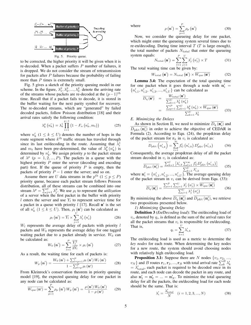
Fig. 5. Priority queue.
to be corrected, the higher priority it will be given when it isre-decoded. When a packet suffers P number of failures, itis dropped. We do not consider the stream of retransmissionfor packets after P failures because the probability of failingmore than P times is extremely small.
Fig. 5 gives a sketch of the priority queuing model in ourscheme. In the figure, λp1, λ
p2, ..., λ
pU denote the arriving rate
of the streams whose packets are re-decoded at the (p−1)th
time. Recall that if a packet fails to decode, it is stored inthe buffer waiting for the next parity symbol for recovery.The re-decoded streams, which are “generated” by faileddecoded packets, follow Poisson distribution [18] and theirarrival rates satisfy the following condition:
λpk(n′k)= λ1
k
p−1∏t=1
(1− Fα
(n′k,mt
))(25)
where n′k (1 ≤ k ≤ U ) denotes the number of hops in theroute segment where kth traffic stream has traveled throughsince its last en/decoding in the route. Assuming that λ1iand mt have been pre-determined, the value of λpk (n
′k) is
determined by n′k. We assign priority p to the packet streamof λp (p = 1, 2, ..., P ). The packets in a queue with thehighest priority P enter the server (decoding and encodingpart) first. If the queue of priority P is empty, then thepackets of priority P − 1 enter the server; and so on.
Assume there are U data streams in the pth (1 ≤ p ≤ P )priority queue, because each packet stream follows Poissondistribution, all of these streams can be combined into onestream λp =
∑Uj=1 λ
pj . We use ρl to represent the utilization
of a server when the first packet in the buffer with priorityl enters the server and use Yl to represent service time fora packet in a queue with priority l [17]. Recall n′ is the setof all n′k (1 ≤ k ≤ U). Then, ρl (n′) can be calculated as
ρl(n′)= Yl ×
U∑j=1
λlj(n′j)
(26)
Wl represents the average delay of packets with priority lpackets and W0 represents the average delay for one taggedwaiting packet due to a packet already in service. W0 canbe calculated as:
W0
(n′)=
P∑l=1
Y 2l
2Yl× ρl
(n′)
(27)
As a result, the waiting time for each of packets is:
Wp
(n′)=W0 (n
′) +∑Pl=p+1 ρl (n
′)Wl (n′)
1−∑Pl=p ρl (n
′)(28)
From Kleinrock’s conservation theorem in priority queuingmodel [19], the expected queuing delay for one packet inany node can be calculated as:
Wque (n′) =
P∑p=1
ρp(n′)Wp
(n′)=ρ (n′)W0 (n
′)
1− ρ (n′) (29)
whereρ(n′)=
P∑p=1
ρp(n′)
(30)
Now, we consider the queueing delay for one packet,which might enter the queueing system several times due tore-en/decoding. During time interval T (T is large enough),the total number of packets Ntotal that enter the queueingsystem equals:
Ntotal
(n′)=
P∑l=1
U∑j=1
λlj(n′j)× T (31)
The total waiting time can be given by:Wtotal
(n′)= Ntotal
(n′)×Wque (n′) (32)
Lemma 3.4: The expectation of the total queuing timefor one packet when it goes through a node with n′i ={n′i,1, n′i,2, n′i,3, ..., n′i,U} can be calculated as
Dq (n′) =Wtotal (n′)∑Uk=1 λ
1k (n
′k)
=
∑Pp=1
∑Uk=1 λ
pk (n
′k)×Wque (n′)∑U
k=1 λ1k
(33)
E. Minimizing the DelaysAs shown in Section II, we need to minimize Dq (n′i) and
Dp&t (n′i) in order to achieve the objective of CEDAR inFormula (2). According to Equ. (24), the prop&tran delayof the packet stream for rk in vi is calculated as:
Dp&t
(n′i,k
)=
∞∑t=1
f tG(n′i,k
)Dt
p&t
(n′i,k
)(34)
Consequently, the average prop&tran delay of all the packetstream decoded in vi is calculated as:
Dp&t (n′i) =
∑Uk=1
[λ′i,k
∑∞t=1 f
tGD
tp&t
(n′i,k
)]∑Uk=1 λ
′i,k
(35)
where n′i = {n′i,1, n′i,2, ..., n′i,U}. The average queuing delayof the packet stream in vi can be derived from Equ. (33):
Dq (n′i) =∑Pi=1
∑Uj=1 λ
lj
(n′j)×Wque (n′i)∑U
j=1 λ1j
(n′j) (36)
By minimizing the above Dq (n′i) and Dp&t (n′i), we retrievetwo propositions presented below.
1) Minimizing Queuing DelayDefinition 3 (En/Decoding load): The en/decoding load of
vi, denoted by qi, is defined as the sum of the arrival rates forall the packet streams that vi is responsible for en/decoding.That is,
qi =U∑k=1
λ′i,k (37)
The en/decoding load is used as a metric to determine thekey nodes for each route. When determining the key nodesfor a new route, the system should avoid choosing nodeswith relatively high en/decoding load.
Proposition 3.1: Suppose there are N nodes {v1, v2, ...,vN} and B routes r1, r2, ..., rB with total arrival rate
∑Bk λ′k
= λ′total, each packet is required to be decoded once in itsroute, and each node can decode the packet in any route, andalso n′1 = n′2 = ... = n′N . To minimize the total queueingdelay for all the packets, the en/decoding load for each nodeshould be the same. That is:
λ′i =λ′totalN
(i = 1, 2, 3, ..., N) (38)
5

Proof: According to Equ. (26), Equ. (27), Equ. (29)and (30), the queuing delay of packets decoded at vki canbe derived as:
Diq (n′) =
ρ (n′)
1− ρ (n′)
∑Pl=1
∑Bk=1 λ
′lk
(n′i,k
)∑Bk=l λ
′1k
W0 =AJλ′2i1− Jλ′i
(39)where A and J are invariants figured by Equ. (30), Equ. (26)and Equ. (25). Then, the following equation can be derived:
N∑i=1
AJλ′2i1− Jλ′i
= −ACλ′total +AN
J+A
J
N∑i=1
1
(1− Jλ′i)(40)
Let Hi = 1 − Jλ′i and then∑Ni=1Hi = N − Jλ′total.
According to Cauchy−Schwarz inequality [18], we find that:N∑i=1
N − Jλ′totalHi
=
N∑i=1
1
Hi
N∑i=1
Hi (41)
=
N∑i=1
1(√Hi)2 N∑
i=1
(√Hi)2≥
(N∑i=1
√1
Hi
√Hi
)2
= N2 (42)
from which, we can derive:N∑i=1
1
(1− Jλ′i)=
N∑i=1
1
Hi≥ N2
N − Jλ′total(43)
and then derive:N∑i=1
AJλ′2i1− Jλ′i
≥ −Aλ′total +AN
J+
AN2
J (N − λ′total)(44)
which reaches its minimum value when 1−Jλ′1 = 1−Jλ′2 =... = 1−Jλ′N , or the values of λ′i (i = 1, 2, .., N) are equalto each other.
According to Proposition 3.1, given several packet streamsand number of nodes required to decode these packets, weneed to balance the en/decoding load for all of these nodes.
2) Minimizing Prop&Tran DelayConsider a route with n hops that is not affected by the
interference from any other routes. Our objective is to divideit into several route segments with the size n1, n2, ..., nerespectively in order to minimize the total delay of packetstream transmission. We consider one of these route segmentthat has nk hops, and use Dave
p&t to denote the averageprop&tran delay for each hop in this route segment. Thatis:
Davep&t (ni) =
Dp&t (ni)
ni(i = 1, 2, 3, ..., e) (45)
where Davep&t (ni) is a function of ni. We use Dave
p&t,min torepresent the minimized value of Dave
p&t (ni), and we need tosearch nopt that satisfies Dave
p&t (nopt) = Davep&t,min,
Proposition 3.2: To divide one route into several routesegments, the optimal length for each route segment shouldbe nopt in order to minimize the prop&tran delay for thepacket delivery.
Proof: The sum of prop&tran delay for the e routesegments equals:
e∑i=1
Dp&t (ni) =
e∑i=1
Dp&t (ni)
ni× ni
≥ Davep&t,min ×
e∑i=1
ni = Davep&t,min × n (46)
When n1 = n2 = ... = ne = nopt,∑ei=1Dp&t (ni) reaches
its minimum value.
IV. SCALABLE AND DISTRIBUTED SCHEME
The objective function of CEDAR in Formula (2) is a non-linear integer programming problem. Solving this problemleads to minimizing the total delay for all the packets in thenetwork. This, however, requires each node collect a globalknowledge of the network including the routes and the arrivalrate for each traffic stream, which is nearly impractical inwireless applications such as wireless ad hoc networks. Eventhough the global knowledge is available, the problem is NP-hard as it is a nonlinear integer programming problem [20].Thus, we need to design a scalable and distributed schemefor identifying the key nodes for each route. Fortunately, thetwo propositions in Section III-E provide foundation for thedesign of a distributed scheme to select key nodes.
Simply put, Proposition 3.1 indicates that the schemeshould try to balance the en/decoding load of each node tominimize the queuing delay; and Proposition 3.2 indicatesthe optimal route segment length (i.e., the positions of keynodes) to minimize the prop&tran delay. If both requirementscan be satisfied simultaneously, the scheme will satisfy theobjective function. However, these two requirements mayconflict with each other. We identify different network trafficload situations that each proposition should be primarily con-sidered, and also propose a method to coordinately considerthese two propositions when choosing key nodes.
Algorithm 1: Identify key nodes in route r executed by eachnode in r in a light-traffic network.
beginSet SEN FIN, REC FIN and DEC to 0 ;while SEN FIN = 0 or REC FIN = 0 do
Listen to other nodes;if it has received ACK REC from the next node in r then
SEN FIN ← 1;
if it receives (OPT HOP, FLAG) from the previous node inr then
REC FIN ← 1;Send ACK REC to the previous node;if FLAG = 0 then
DEC ← 1 // It is a key node;FLAG ← OPT HOP;
elseFLAG ← FLAG - 1;
Case I (light traffic): When a wireless network has lighttraffic, because the influence from queuing delay is muchless significant, we mainly consider the prop&tran delay.As Proposition 3.2 indicates, we first search the value ofnopt and then set OPT HOP = nopt, and set FLAG= OPT HOP. In a routing algorithm [21], every node keepsa routing table, and a source node sends out a messageto find the route to a destination for transmitting a packetstream. After a source-destination route has been discovered,each node in the route determines whether it is a keynode in a distributed manner by executing the key nodeidentification algorithm. Algorithm 1 presents the pseudocode of this algorithm executed by every node (except sourcenode and destination node), say v, in a route r in the caseof light network traffic. Here, SEN FIN presents whetherv has received ACK from the next node in r; REC FINpresents whether v has received (OPT HOP, FLAG) from the
6
previous node in r; DEC presents whether v is responsiblefor en/decoding;
Case II (heavy traffic): When a wireless network hasheavy traffic, we aim to balance the en/decoding load foreach node through the route to reduce queuing delay whilereducing the prop&tran delay. When a new route is built, theCEDAR scheme first executes Algorithm 1. Simultaneouslyeach node along the route piggybacks its en/decoding loadto the packet, and the last node sends the informationback. Then the source node knows the series of nodesidentified as “potential key nodes” and their en/decodingloads, and calculates the average en/decoding load throughthe route, denoted as AVE LOAD. It then checks whether theen/decoding load of each identified key node is larger thana pre-defined threshold (AVE LOAD + BOUND), whereBOUND is a predetermined value. An overloaded potentialkey node probes its nearby nodes sequentially until finding anode with load within the threshold or meeting an identifiedpotential key node. The pseudocode of this algorithm ispresented in Algorithm 2.
Algorithm 2: Select key nodes with consideration of loadbalance in a heavy-traffic or normal-traffic network.
beginUse Algorithm 1 to get the “potential key nodes” in route r;Let node i be one node selected as the “potential key node”;j = 0;while j ≤ bOPT HOP/2c do
if LOADi+j ≤ LOADi−j thenif LOADi+j ≤ (BOUND+AVE LOAD) then
return i+ j;
elseif LOADi−j ≤ (BOUND+AVE LOAD) then
return i− j;
j = j + 1;
return 0;
V. PERFORMANCE EVALUATION
This section presents the results of experiments onNESTbed [22] and simulation with MATLAB. We comparedCEDAR with the global optimal solution (OPTIMAL), thetraditional link-layer protocols, where packet is decodedhop by hop [6], [14] (HBH), and with another solutionwhere packet is only decoded at the destination (DEST). Inorder to evaluate the effect of the load balancing algorithm(Algorithm 2) in CEDAR, we also test the performance ofCEDAR without this algorithm denoted by CEDAR*.A. Experiments on Real-World NESTbed
NESTbed is an open testbed for developing wirelesssensor systems [22]. It is a collection of 80 TELOSB sensors(Fig. 8 (a)) that are arranged in a grid (Fig. 8 (b)). Thesensors have CC2420 Chip and communicate using theIEEE 802.15.4 standard. We verify our mathematical modelsand evaluate the performance of CEDAR on NESTbed. Wecreated a multi-hop network of TELOSB sensors runningTiny-OS 2.1.0 written in NESC. We use Reed-Solomoncodes to detect and fix errors in a packet, if the numberof error bits exceeds the capability of Reed-Solomon codesfor correction, the receiver ask for retransmission.
(a) TELOSB sensors (b) NESTbedFig. 6. Experiment.
0 5 10 15 20 25 30 350
0.05
0.1
0.15
0.2
0.25
Number of hops
BE
R
commonnoises
(a) BER in multiple hops
1214
1618
2022 0
1020
3040
60%
80%
100%
80%
90%
100%
Number of hopsLength of parity symbols
Pro
babi
lity
of s
ucce
ssfu
l dec
odin
g
(b) Successful decoding rateFig. 7. Comparison of results.
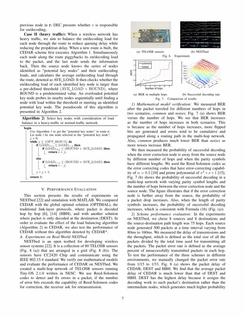
1) Mathematical model verification: We measured BERafter the packet traveled for different numbers of hops intwo scenarios, common and noises. Fig. 7 (a) shows BERversus the number of hops. We see that BER increasesas the number of hops increases in both scenarios. Thisis because as the number of hops increases, more flippedbits are generated and errors tend to be cumulative andpropagated along a routing path in the multi-hop network.Also, common produces much lower BER than noises asmore noises increase BER.
We then measured the probability of successful decodingwhen the error correction node is away from the source nodeby different number of hops and when the parity symbolshave different lengths. We used the Reed-Solomon codes asthe error correcting codes that have error-correcting capabil-ity of α = 0.5 [10] and prime polynomial of x3+x+1 [15].Fig. 7 (b) shows the probability of successful decoding in amulti-hop network with varying parity symbol lengths andthe number of hops between the error correction node and thesource node. The figure illustrates that if the error correctionnode is further away from the source, the probability ofa packet drop increases. Also, when the length of paritysymbols increases, the probability of successful decodingincreases, which is consistent with Formula (16) (Fig. (a)).
2) Scheme performance evaluation: In the experimentson NESTbed, we chose 8 sources and 8 destinations andthe source-destination path length was 75 hops. Each sourcenode generated 500 packets at a time interval varying from80ms to 160ms. We measured the delay of transmissions andthe throughput, which is defined as the total size of all thepackets divided by the total time used for transmitting allthe packets. The packet error rate is defined as the averagepercent of unsuccessfully transmitted packets in each hop.To test the performance of the three schemes in differentenvironments, we manually changed the packet error ratefrom 1/15 to 1/33. Fig. 8 (a) shows the packet delay ofCEDAR, DEST and HBH. We find that the average packetdelay of CEDAR is much lower than that of DEST andHBH. DEST has the highest delay because it assigns thedecoding work to each packet’s destination rather than theintermediate nodes, which generates much higher probability
7

1/15 1/17 1/19 1/21 1/23 1/25 1/27 1/29 1/31 1/331000
1500
2000
2500
3000
3500
4000
4500
5000
Packet error rate
Pac
ket d
elay
(ms)
DESTHBHCEDAR
(a) Packet delay
1/15 1/17 1/19 1/21 1/23 1/25 1/27 1/29 1/31 1/3350
100
150
200
250
300
350
Packet error rate
Thro
ughp
ut (k
bps)
DESTHBHCEDAR
(b) ThroughputFig. 8. Experimental results on real-world NESTbed.
0.5 1.0 1.5 2.0 2.5 3.0 3.5 4.0 4.5 5.0 5.50
0.5
1
1.5
2
2.5
3
3.5
4
Packet generating rate per source node (packts/msec)
Del
ay (m
sec)
Prop&tran delay
Queuing delay
(a) DEST
0.5 1.0 1.5 2.0 2.5 3.0 3.5 4.0 4.5 5.0 5.50
0.5
1
1.5
2
2.5
3
3.5
4
Packet generating rate persource node (packts/msec)
Del
ay (m
sec)
Prop&tran delayQueuing delay
(b) HBH
0.5 1.0 1.5 2.0 2.5 3.0 3.5 4.0 4.5 5.0 5.50
0.5
1
1.5
2
2.5
3
3.5
4
Packet generating rate per source node (packts/msec)
Del
ay (m
sec)
Prop&tran delayqueuing delay
(c) CEDAR*
0.5 1.0 1.5 2.0 2.5 3.0 3.5 4.0 4.5 5.0 5.50
0.5
1
1.5
2
2.5
3
3.5
4
Packet generating rate per source node (packts/msec)
Del
ay (m
sec)
Prop&tran delayQueuing delay
(d) CEDARFig. 9. Prop&tran delay and queuing delay.
of packet re-decoding due to higher probability of packeterrors, thus increasing the delay. The delay of HBH is higherthan that of CEDAR because HBH requires packets to been/decoded in each hop, which generates high en/decodingload on intermediate nodes, leading to high queuing delay.Fig. 8 (b) shows the throughput of three schemes. From thefigure, we can find that the throughput follows CEDAR >HBH > DEST. This is because lower packet transmissiondelay usually leads to higher throughput in the network.
B. Simulation on MatlabWe conducted simulation on Matlab to evaluate the perfor-
mance of CEDAR. We built a 9×9 grid network with eachnode located in one grid and randomly selected 16 pairs ofsource node and destination node. Each packet contains 20data symbols, 5 type-I parity symbols and 5 type-II paritysymbols. Each symbol has 5 bits. Also, we randomly chosenodes connecting each pair of source node and destinationnode as the route.
Fig. 9 (a), (b), (c) and (d) compare prop&tran delay andqueuing delay computed by HBH, DEST, CEDAR* andCEDAR respectively. From the figure we can find that: (1)the queuing delay increases as the generating rate of eachdata stream increases but the prop&tran delay remains nearlyconstant; (2) the queuing delay increases more significantlyin HBH than in DEST and CEDAR (i.e., it follows CEDAR< DEST < HBH); (3) for prop&tran delay it followsHBH < CEDAR < DEST, (4) CEDAR generates the sameprop&tran delay but lower queuing delay than CEDAR*,and (5) the total packet delay follows CEDAR < CEDAR*< DEST < HBH. For (1), this is because queuing delayis determined by the generating rate of the source node
0.5 1 1.5 2 2.5 3 3.5 4 4.5 5 5.50.2
0.4
0.6
0.8
1
1.2
1.4
1.6
Arrival rate (packet/msec)
Del
ay (
mse
c)
CEDAROPTIMALHBHDEST
(a) Average packet delay
0.5 1 1.5 2 2.5 3 3.5 4 4.5 5 5.50
1000
2000
3000
4000
5000
Arrival rate (packet/msec)
Del
ay (
mse
c)
CEDAROPTIMALHBHDEST
(b) ThroughputFig. 10. Packet delay and throughput.
1100 1200 1300 1400 1500 1600 1700 1800 1900 20000.5
1
1.5
2
2.5
3
3.5
4
4.5
Service rate (bit/msec)
Del
ay (m
sec)
DESTHBHCEDAR*CEDAR
(a) Average packet delay
1100 1200 1300 1400 1500 1600 1700 1800 1900 20001550
1600
1650
1700
1750
1800
1850
1900
Service rate (bit/msec)
Thro
ughp
ut (b
it/m
sec)
DESTHBHCEDAR*CEDAR
(b) ThroughputFig. 11. Packet delay and throughput (with OPTIMAL).
but the prop&tran delay is independent of it. For (2), (4)and (5), HBH has higher queuing delay since it generatesmore en/decoding load on intermediate nodes. In contrastto HBH, DEST only assigns the decoding work to eachpacket’s destination, which increases both prop&tran delayand queuing delay due to higher probability of packet re-decoding (as Equ. (18) shows). Instead of accumulatingdecoding work on the destinations, CEDAR* and CEDARchooses a number of intermediate nodes to be responsiblefor the en/decoding work to reduce the probability of re-decoding. CEDAR performs better than CEDAR* becauseCEDAR distributes the en/decoding load of the intermediatenodes more evenly, which reduces the queuing delay asindicated in Proposition 3.1
Fig. 11 (a) compares the average packet delay of HBH,DEST, CEDAR* and CEDAR with various service rates.The results is consistent with the results in Fig. 9. Also, wefind that CEDAR produces higher throughput than CEDAR*,DEST and HBH in Fig. 11 (b). This is because lower packettransmission delay usually leads to higher throughput inthe network. Fig. 10 (a) and (b) compares OPTIMAL withCEDAR, CEDAR*, DEST and HBH in terms of packet delayand throughput. Considering NP-hard feature of the problem,we only set a small scale network (6 source nodes and 6destination nodes). The results demonstrate that CEDAR canachieve almost the “best” performance in terms of packetdelay even in the distributed manner.
VI. RELATED WORK
The link-layer protocol of the current TCP/IP stack hasadopted variations of error recovery mechanisms to providereliability for point-to-point communication especially forwireless systems. Different wireless communication stan-dards currently utilize variations of error control protocolsthat generally can be categorized into ARQ [12] and HARQ-based [5], [11] protocols. For instance IEEE802.11 WiFiuses ARQ where a receiving node discards corrupted packets(even when there is only a single bit error) and requests fora retransmission. The 4G/LTE deploys HARQ with TurboCodes where the sender node encodes the packet payload
8
using Turbo channel codes [23] prior to the transmission.Accordingly, the receiver node requests for a retransmissionwhen the decoding of the received packet fails. In conjunc-tion with the current wireless link-layer standards, there issignificant work and research conducted to imporve the per-formance of either ARQ- or HARQ-based protocols. Severalkinds of HARQ protocols (see [5], [11] and the referencetherein) improve the throughput of the ARQ schemes bypacket combining, e.g. by keeping the erroneous receivedpackets and utilizing them for detection and packet recovery.Examples of recent efforts for combating the inefficiencyof ARQ-based wireless protocols include Partial Packet Re-covery (PPR) [9], Cross-Layer Design with Side-information(CLDS), and Automatic Code Embedding (ACE) framework[14]. Some of these approaches, such as PPR and SOFT,exploit physical layer information regarding the quality ofindividual bits to increase the probability of recoveringcorrupted packets. Other schemes, such as CLDS and ACE,utilize information available in the current 802.11 link-layerprotocols in conjunction with error correcting codes to re-cover corrupted packets. Ilyas et al. [24] proposed the “PoorMan’s SIMO System” (PMSS) to reduce packet losses in net-works of commodity IEEE 802.15.4 sensor motes using co-operative communication and diversity combination. Basedon mathematical analysis, Jelenkovi et al. [4] proposed a newdynamic packet fragmentation algorithm that can adaptivelymatch channel failure characteristics. These aforementionedworks have significantly improved the ARQ- and HARQ-based link-layer performance and provide a comprehensiveerror control approach for wireless communication. Howevervirtually all of these efforts follow the conventional TCP/IPlink-layer “store-and-forward” design paradigm where eachrelay node verifies the correctness of each packet beforeforwarding it to the next node. This inherently introducessubstantial overhead on bandwidth utilization and throughputand the overall end-to-end delay.
VII. CONCLUSION
In this paper, our objective is to find an optimal so-lution to choose immediate nodes in transmission routesfor en/decoding packets in wireless networks in order tominimize the packet delay and increase the throughput.We mathematically analyze the packet delay and modelthe problem as an integer programming problem, whichhelps to discover a globally optimal solution. Taking intoaccount the scalability of the network and limitation ofthe information that each node can collect, we propose adistributed scheme that can achieve performance comparableto the globally optimal solution. The simulation results inMATLAB demonstrates that our scheme performs better thanprevious packet recovery schemes. In our future work, weaim to use random graph to analyze wireless networks (e.g.,mobile ad-hoc network) where the network topology variesfrequently for accurate formulation of the stochastic of thenetwork.
ACKNOWLEDGEMENTS
This research was supported in part by U.S. NSFgrants OCI-1064230, CNS-1249603, CNS-1049947, CNS-
1156875, CNS-0917056 and CNS-1057530, CNS-1025652,CNS-0938189, CSR-2008826, CSR-2008827, Microsoft Re-search Faculty Fellowship 8300751, and U.S. Departmentof Energy’s Oak Ridge National Laboratory including theExtreme Scale Systems Center located at ORNL and DoD4000111689.
REFERENCES
[1] R. Cohen and L. Grebla, G.and Katzir, “Cross-layer hybrid fec/arqreliable multicast with adaptive modulation and coding in broadbandwireless networks,” in Proc. of INFOCOM, 2009.
[2] Z. Guo, J. Huang, and et al., “A practical joint network- channel codingscheme for reliable communication in wireless networks,” in Proc. ofMobiHoc, 2009.
[3] G. Woo, P. Kheradpour, D. Shen, and D. Katabi, “Beyond the bits:Cooperative packet recovery using physical layer information,” inProc. of MOBICOM, 2007.
[4] P. R. Jelenkovi and J. Tan, “Dynamic packet fragmentation for wirelesschannels with failures,” in Proc. of MobiHoc, 2008.
[5] E. C. Strinati, S. Simoens, and J. Boutros, “Performance evaluation ofsome hybrid arq schemes in ieee 802.11a networks,” in Proc. of VTS,2003.
[6] K. C. Lin, N. Kushman, and D. Katabi., “Harnessing partial packetsin 802.11 networks,” in Proc. of MOBICOM, 2008.
[7] S. S. Karande and H. Radha, “Non-linear integer programming bydarwin and boltzmann mixed strategy,” IEEE Transactions On Multi-media, 2008.
[8] M. Ghaderi, D. Towsley, J. Kurose, U. of Calgary, and Calgary,“Reliability gain of network coding in lossy wireless networks,” inProc. of INFOCOM, 2008.
[9] K. Jamieson and H. Balakrishnan, “PPR: Partial packet recovery forwireless networks,” in Proc. of SIGCOMM, 2007.
[10] S. Soltani, K. Misra, and H. Radha, “Delay constraint error controlprotocol for real-time video communication,” IEEE Transaction onMultimedia, 2009.
[11] H. Yomo, S. S. Chakraborty, and R. Prasad, “PHY and MAC per-formance evaluation of IEEE 802.11a WLAN over fading channels,”IEEE Transaction on Multimedia, 2009.
[12] S. Lin and D. J. Costello, Error Control Coding: Fundamentals andApplications. NJ: Prentice-Hall: Englewood Cliffs, 2004.
[13] H. S. Wang and N. Moayeri, “Finite-state markov channel - a usefulmodel for radio communication channels,” IEEE Transactions onvehicular technolgoy, 1995.
[14] S. Soltani, K. Misra, and H. Radha, “On link-layer reliability andstability for wireless communication,” in Proc. of MOBICOM, 2008.
[15] S. Wicker and V. Bhargava, “Institute of electrical and electronicsengineering, inc,” IEEE Press, 1994.
[16] M. Mandelbaum, M. Hlynka, and P. H. Brill, “Nonhomogeneousgeometric distributions with relations to birth and death processes,”Springer J. TOP Business Econ., 2007.
[17] J. L. Hammond and P. J. O’Reilly, Performance Analysis of LocalComputer Networks. Reading, Massachusetts: Addison-Wesley Pub-lishing Company, 1988.
[18] S. Chahramant, Fundamentals of Probability with Stochastic Process.Reading, Massachusetts: Western New England College, 1986.
[19] V. B. Iversen, Teletraffic Engineering Handbook. Technical Universityof Denmark, 2001.
[20] P. Tian, J. Ma, and D.-M. Zhang, “Non-linear integer programmingby darwin and boltzmann mixed strategy,” European Journal ofOperational Research, 1996.
[21] L. L. Peterson and B. S. Davie, Computer network: a system approach.Morgan Kaufmann, 2007.
[22] A. R. Dalton and J. O. Hallstrom, “An interactive, source-centric,open testbed for developing and profiling wireless sensor systems,”International Journal of Distributed Sensor Networks, March 2009.
[23] D.N.Rowitch and L.B.Milstein, “On the performance of hybrid fec/arqsystems using rate-compatible low-density parity-check codes.” ITC,2000.
[24] M. Ilyas, M. Kim, and H. Radha, “Reducing packet losses in net-works of commodity IEEE 802.15.4 sensor motes using cooperativecommunication and diversity combination,” in Proc. of INFOCOM,2009.
9


![[slides] Parallel and Distributed Computing on Low Latency Clusters](https://static.fdocuments.us/doc/165x107/5466a74cb4af9ff5748b4830/slides-parallel-and-distributed-computing-on-low-latency-clusters.jpg)