CE MultiTesterXA MI 3394 Instruction manual€¦ · the CE MultiTesterXA instrument, as well as to...
109
CE MultiTesterXA MI 3394 Instruction manual Ver. 1.3, Code no.20 752 432
Transcript of CE MultiTesterXA MI 3394 Instruction manual€¦ · the CE MultiTesterXA instrument, as well as to...

CE MultiTesterXA MI 3394
Instruction manual Ver. 1.3, Code no.20 752 432

2
Distributor: Manufacturer: Metrel d.d. Ljubljanska cesta 77 SI-1354 Horjul E-mail: [email protected] http://www.metrel.si
Mark on your equipment certifies that it meets European Union requirements for EMC, LVD, ROHS regulations
© 2015 Metrel The trade names Metrel, Smartec, Eurotest, Autosequence are trademarks registered or pending in Europe and other countries No part of this publication may be reproduced or utilized in any form or by any means without permission in writing from METREL.

MI 3394 CE MultiTesterXA Table of contents
3
TABLE OF CONTENTS 1 General description ........................................................................................................ 6
1.1 Warnings and notes ...................................................................................................... 6 1.1.1 Safety warnings ........................................................................................................ 6 1.1.2 Warnings related to safety of measurement functions .............................................. 6
1.1.2.1 HV AC, HV DC, HV AC programmable, HV DC programmable ....................... 6 1.1.2.2 Diff. Leakage, Ipe Leakage, Touch Leakage, Power, Leak’s & Power ............. 7
1.1.3 Markings on the instrument ....................................................................................... 7 1.2 Standards applied ......................................................................................................... 7
2 Instrument set and accessories .................................................................................... 9
2.1 Standard set of the instrument ...................................................................................... 9 2.2 Optional accessories ..................................................................................................... 9
3 Instrument description ................................................................................................. 10
3.1 Front panel .................................................................................................................. 10
4 Instrument operation .................................................................................................... 12
4.1 General meaning of keys ............................................................................................ 12 4.2 General meaning of touch gestures: ........................................................................... 12 4.3 Safety checks .............................................................................................................. 13 4.4 Symbols and messages .............................................................................................. 13 4.5 Instrument main menu ................................................................................................ 17 4.6 General settings .......................................................................................................... 18
4.6.1 Language ................................................................................................................ 19 4.6.2 Date and time .......................................................................................................... 19 4.6.3 Profiles .................................................................................................................... 19 4.6.4 Workspace Manager ............................................................................................... 19 4.6.5 Auto test groups ...................................................................................................... 19 4.6.6 Change password for HV functions......................................................................... 20 4.6.7 Settings ................................................................................................................... 20 4.6.8 Initial Settings .......................................................................................................... 20 4.6.9 About ....................................................................................................................... 21
4.7 Instrument profiles ...................................................................................................... 21 4.8 Workspace Manager ................................................................................................... 22
4.8.1 Workspaces and Exports ........................................................................................ 22 4.8.2 Workspace Manager main menu ............................................................................ 23
4.8.2.1 Operations with Workspaces .......................................................................... 24 4.8.2.2 Operations with Exports .................................................................................. 24 4.8.2.3 Adding a new Workspace ............................................................................... 25 4.8.2.4 Opening a Workspace .................................................................................... 26 4.8.2.5 Deleting a Workspace / Export ....................................................................... 26 4.8.2.6 Importing a Workspace ................................................................................... 27 4.8.2.7 Exporting a Workspace ................................................................................... 28
4.9 Auto test groups .......................................................................................................... 29 4.9.1 Auto test groups menu ............................................................................................ 29
4.9.1.1 Operations in Auto test groups menu: ............................................................ 29 4.9.1.2 Selecting a list of Auto tests ............................................................................ 30 4.9.1.3 Deleting a list of Auto tests ............................................................................. 30
5 Memory Organizer......................................................................................................... 32
5.1 Memory Organizer menu ............................................................................................ 32

MI 3394 CE MultiTesterXA Table of contents
4
5.1.1 Measurement statuses ............................................................................................ 33 5.1.2 Structure Objects .................................................................................................... 33
5.1.2.1 Measurement status indication under the Structure object ............................. 34 5.1.3 Operations in Tree menu ........................................................................................ 35
5.1.3.1 Operations on measurements (finished or empty measurements) ................. 35 5.1.3.2 Operations on Structure objects ..................................................................... 36 5.1.3.3 View / Edit parameters and attachments of a Structure object ....................... 37 5.1.3.4 Add a new Structure Object ............................................................................ 38 5.1.3.5 Add a new measurement ................................................................................ 39 5.1.3.6 Clone a Structure object ................................................................................. 40 5.1.3.7 Clone a measurement..................................................................................... 41 5.1.3.8 Copy & Paste a Structure object ..................................................................... 42 5.1.3.9 Copy & Paste a measurement ........................................................................ 43 5.1.3.10 Delete a Structure object ................................................................................ 44 5.1.3.11 Delete a measurement.................................................................................... 45 5.1.3.12 Rename a Structure object ............................................................................. 46
6 Single tests .................................................................................................................... 47
6.1 Selection of single tests .............................................................................................. 47 6.1.1 Single test screens .................................................................................................. 48 6.1.2 Setting parameters and limits of single tests........................................................... 49 6.1.3 Single test start screen ........................................................................................... 50 6.1.4 Single test screen during test .................................................................................. 51 6.1.5 Single test result screen .......................................................................................... 51 6.1.6 Single test memory screen...................................................................................... 53 6.1.7 Help screens ........................................................................................................... 53
6.2 Single test measurements .......................................................................................... 54 6.2.1 Continuity ................................................................................................................ 54 6.2.2 HV AC ..................................................................................................................... 55 6.2.3 HV DC ..................................................................................................................... 57 6.2.4 HV AC programmable ............................................................................................. 59 6.2.5 HV DC programmable ............................................................................................. 61 6.2.6 Insulation resistance (Riso, Riso-S) ........................................................................ 63 6.2.7 Sub-leakage (Isub, Isub-S) ..................................................................................... 65 6.2.8 Differential Leakage ................................................................................................ 68 6.2.9 Ipe Leakage ............................................................................................................ 70 6.2.10 Touch Leakage ................................................................................................... 71 6.2.11 Power .................................................................................................................. 73 6.2.12 Leak's & Power ................................................................................................... 74 6.2.13 Discharging Time ................................................................................................ 76
7 Auto tests....................................................................................................................... 80
7.1 Selection of Auto tests ................................................................................................ 80 7.2 Organization of Auto tests ........................................................................................... 80
7.2.1 Auto test view menu ................................................................................................ 81 7.2.1.1 Auto test view menu (header is selected) ....................................................... 81 7.2.1.2 Auto test view menu (measurement is selected) ............................................ 81 7.2.1.3 Indication of Loops .......................................................................................... 82
7.2.1 Step by step excecution of Auto tests ..................................................................... 82 7.2.2 Auto test result screen ............................................................................................ 84 7.2.3 Auto test memory screen ........................................................................................ 86
8 Maintenance .................................................................................................................. 87
8.1 Periodic calibration ...................................................................................................... 87 8.2 Fuses .......................................................................................................................... 87

MI 3394 CE MultiTesterXA Table of contents
5
8.3 Service ........................................................................................................................ 87 8.4 Cleaning ...................................................................................................................... 87
9 Communications ........................................................................................................... 88
9.1 USB and RS232 communication with PC ................................................................... 88 9.2 Bluetooth communication ............................................................................................ 88 9.3 RS232 communication with other external devices .................................................... 89 9.4 Connections to test adapters ...................................................................................... 89
9.4.1 Test connector TC1 ................................................................................................ 89 9.5 INPUTs ....................................................................................................................... 90 9.6 OUTPUTs ................................................................................................................... 90
10 Technical specifications............................................................................................... 91
10.1 HV AC, HV AC programmable .................................................................................... 91 10.2 HV DC, HV DC programmable ................................................................................... 91 10.3 Continuity .................................................................................................................... 92 10.4 Insulation Resistance, Insulation Resistance-S .......................................................... 92 10.5 Substitute Leakage Current, Substitute Leakage Current - S ..................................... 93 10.6 Differential Leakage current ........................................................................................ 93 10.7 PE leakage current ..................................................................................................... 94 10.8 Touch leakage current ................................................................................................ 94 10.9 Power .......................................................................................................................... 95 10.10 Leak’s & Power ....................................................................................................... 96 10.11 Discharging time ..................................................................................................... 97 10.12 General data ........................................................................................................... 98
Appendix A - Structure objects in CE MultiTesterXA .......................................................... 100
Appendix B - Profile Notes .................................................................................................... 101
Appendix C - Default list of Auto tests ................................................................................. 102
Appendix D - Programming of Auto tests on Metrel ES Manager ...................................... 103
D.1 Auto test editor workspace ........................................................................................ 103 D.2 Managing groups of Auto tests ................................................................................. 104 D.3 Elements of an Auto test ........................................................................................... 105
D.3.1 Auto test steps .................................................................................................. 105 D.3.2 Single tests ........................................................................................................ 106 D.3.3 Flow commands ................................................................................................ 106 D.3.4 Number of measurement steps ......................................................................... 106
D.4 Creating / modifying an Auto test .............................................................................. 106 D.5 Description of flow commands .................................................................................. 107
MI 3394 CE MultiTesterXA General description
6
1 General description
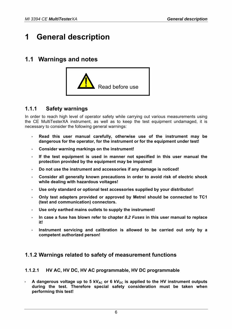
1.1 Warnings and notes
Read before use
1.1.1 Safety warnings In order to reach high level of operator safety while carrying out various measurements using the CE MultiTesterXA instrument, as well as to keep the test equipment undamaged, it is necessary to consider the following general warnings:
Read this user manual carefully, otherwise use of the instrument may be dangerous for the operator, for the instrument or for the equipment under test!
Consider warning markings on the instrument!
If the test equipment is used in manner not specified in this user manual the protection provided by the equipment may be impaired!
Do not use the instrument and accessories if any damage is noticed!
Consider all generally known precautions in order to avoid risk of electric shock while dealing with hazardous voltages!
Use only standard or optional test accessories supplied by your distributor!
Only test adapters provided or approved by Metrel should be connected to TC1 (test and communication) connectors.
Use only earthed mains outlets to supply the instrument!
In case a fuse has blown refer to chapter 8.2 Fuses in this user manual to replace it!
Instrument servicing and calibration is allowed to be carried out only by a competent authorized person!
1.1.2 Warnings related to safety of measurement functions
1.1.2.1 HV AC, HV DC, HV AC programmable, HV DC programmable A dangerous voltage up to 5 kVAC or 6 kVDC is applied to the HV instrument outputs
during the test. Therefore special safety consideration must be taken when performing this test!

MI 3394 CE MultiTesterXA General description
7
Only a skilled person familiar with hazardous voltages can perform this measurement!
DO NOT perform this test if any damage or abnormality (test leads, instrument) is noted!
Never touch exposed probe tip, connections equipment under test or any other energized part during the measurements. Make sure that NOBODY can contact them either!
DO NOT touch any part of test probe in front of the barrier (keep your fingers behind the finger guards on the probe) – possible danger of electric shock!
It is a good practice to use lowest possible trip-out current. 1.1.2.2 Diff. Leakage, Ipe Leakage, Touch Leakage, Power, Leak’s & Power It is advisable not to run tested devices with load currents above 10 A for more than
15 minutes. Load currents higher than 10 A can result in high temperatures of On/Off switch and fuse holders!
1.1.3 Markings on the instrument
Read the Instruction manual with special care to safety operation«. The symbol requires an action!
Dangerous high voltage is present on terminals during the test. Consider all precautions in order to avoid risk of electric shock.
Mark on your equipment certifies that it meets European Union requirements for EMC, LVD, and ROHS regulations.
This equipment should be recycled as electronic waste.
1.2 Standards applied
The CE MultiTesterXA instrument is manufactured and tested according to the following regulations, listed below. Electromagnetic compatibility (EMC) EN 61326-1 Electrical equipment for measurement, control and laboratory use - EMC
requirements – Part 1: General requirements Class B (Portable equipment used in controlled EM environments)
Safety (LVD)

MI 3394 CE MultiTesterXA General description
8
EN 61010-1 Safety requirements for electrical equipment for measurement, control, and laboratory use – Part 1: General requirements
EN 61010-2-030 Safety requirements for electrical equipment for measurement, control and laboratory use – Part 2-030: Particular requirements for testing and measuring circuits
EN 61010-031 Safety requirements for electrical equipment for measurement, control and laboratory use – Part 031: Safety requirements for hand-held probe assemblies for electrical measurement and test
EN 61557
Electrical safety in low voltage distribution systems up to 1 000 V a.c. and 1 500 V d.c. – Equipment for testing, measuring or monitoring of protective measures Instrument complies with all relevant parts of EN 61557 standards.
Functionality EN 60335 Household and similar electrical appliances EN 60950 Information technology equipment – Safety EN 61439 Low-voltage switchgear and controlgear assemblies
EN 61010 Safety requirements for electrical equipment for measurement, control, and laboratory use
EN 60598 Safety of lighting equipment
VDE 0701-702
Inspection after repair, modification of electrical appliances – Periodic inspection on electrical appliances General requirements for electrical safety
EN 50191 Erection and operation of electrical test equipment

MI 3394 CE MultiTesterXA Instrument set and accessories
9
2 Instrument set and accessories
2.1 Standard set of the instrument
Instrument MI 3394 CE MultitesterXA Bag for accessories HV test probes 2 m, 2 pcs Continuity test lead set 2.5 m, 2 pcs Continuity test lead red 1.5 m / 2.5 mm2 Test lead black 2.5 m Test lead red 2.5 m Alligator clips black 3 pcs Alligator clips red 2 pcs Mains cable RS232 cable USB cable Calibration Certificate Short form instruction manual CD with instruction manual (full version) and PC SW Metrel ES Manager
2.2 Optional accessories
See the attached sheet for a list of optional accessories that are available on request from your distributor.

MI 3394 CE MultiTesterXA Instrument description
10
3 Instrument description
3.1 Front panel
Figure 3.1: Front panel
1 Mains supply connector 2 F1, F2 fuses (F 5 A / 250 V) 3 F3, F4 fuses (T 16 A / 250 V) 4 On / Off switch 5 Test connections TC1 for external test adapters 6 Mains test socket 7 P/S (probe) connector 8 Keypad 9 HV output connectors 10 HV output warning lamp 11 Continuity connectors 12 Insulation / Subleakage connectors 13 Discharging time connectors 14 Colour TFT display with touch screen 15 Control outputs 16 Control inputs 17 Multipurpose RS232-1 port

MI 3394 CE MultiTesterXA Instrument description
11
18 Multipurpose RS232-2 port
19 Ethernet connector (not yet functional in this model) 20 USB connector 21 MicroSD card slot

MI 3394 CE MultiTesterXA Instrument operation
12
4 Instrument operation The CE MultiTesterXA can be manipulated via a keypad or touch screen.
4.1 General meaning of keys
Cursor keys are used to: - select appropriate option
Enter key is used to: - confirm selected option - start and stop measurements
Escape key is used to: - return to previous menu without changes - abort measurements
Option key is used to: - expand column in control panel - show detailed view of options
HV Test key is used to: - start and stop HV tests
4.2 General meaning of touch gestures:
Tap (briefly touch surface with fingertip) is used to: - select appropriate option - confirm selected option - start and stop measurements
Swipe (press, move, lift) up/ down is used to: - scroll content in same level - navigate between views in same level
long
Long press (touch surface with fingertip for at least 1 s) is used to: - select additional keys (virtual keyboard) - enter cross selector from single test screens
Tap Escape icon is used to: - return to previous menu without changes; - abort measurements

MI 3394 CE MultiTesterXA Instrument operation
13
4.3 Safety checks
At start up and during operation the instrument performs various safety checks to ensure safety and to prevent any damage. These safety pre-tests are checking for: Correct input mains voltage Presence of input PE connection, Any external voltage against earth on mains test socket Excessive leakage currents through measuring I/Os, Too low resistance between L and N of tested device, Proper operation of safety relevant internal electronic circuits
If a safety check fails, an appropriate warning message will be displayed and safety measures will be taken. The warnings and safety measures are described in chapter 4.4 Symbols and messages.
4.4 Symbols and messages
Supply voltage warning
Possible causes:
No earth connection.
Instrument is connected to an IT earthing system. Press YES to continue normally or NO to continue in a limited mode (measurements are disabled).
Warning:
The instrument must be earthed properly to work safely!
Resistance L-N > 30 kΩ
In pre-test a high input resistance was measured. Possible causes:
Device under test is not connected or switched on
Input fuse of device under test is blown.
Select YES to proceed with or NO to cancel measurement.
Resistance L-N < 10 Ω
In pre-test a very low resistance of the device under test supply input was measured. This can result in a high current after applying power to the device under test. If the too high current is only of short duration (caused by a short inrush current) the test can be performed otherwise not.
Select YES to proceed with or NO to cancel measurement

MI 3394 CE MultiTesterXA Instrument operation
14
Resistance L-N < 30 Ω
In pre-test a low input resistance of the device under test was measured. This can result in a high current after applying power to the device. If the high current is only of short duration (caused by a short inrush current) the test can be performed, otherwise not.
Select YES to proceed with or NO to cancel measurement.
Warning for improper supply voltage condition. If pressing OK instrument will continue to work in a limited mode (measurements are disabled).
In pre-test an external voltage between C1/P1 and C2/P2 terminals was detected. The measurement was cancelled. Press OK to continue.
In pre-test a too high external voltage was detected between P and PE terminals. The measurement was cancelled. Press OK to continue.
In pre-test a too high external voltage was detected between ISO/SUB and PE terminals. The measurement was cancelled. Press OK to continue.
In pre-test a possible high leakage current was detected. It is likely that a dangerous leakage current (higher than 3.5 mA) will flow after applying power to the device under test.
Select YES to proceed with or NO to cancel measurement.
The measured leakage (Idiff, Ipe, Itouch) current was higher than 20 mA. Measurement was aborted. Press OK to continue.
MI 3394 CE MultiTesterXA Instrument operation
15
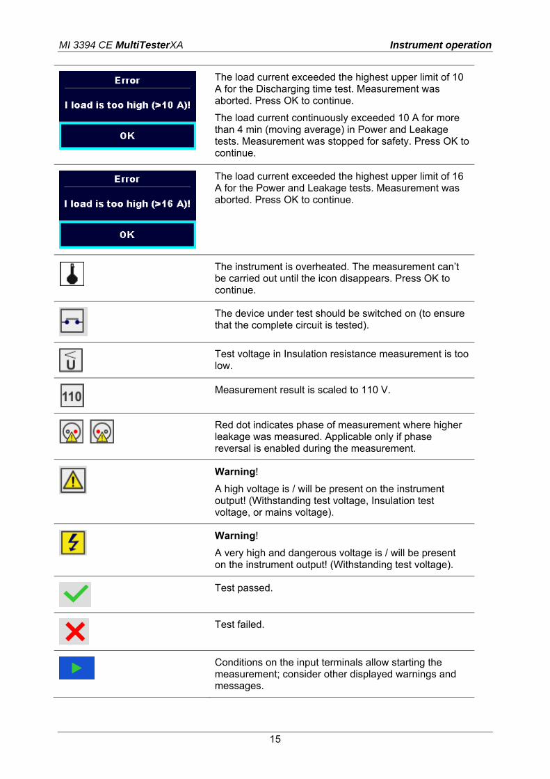
The load current exceeded the highest upper limit of 10 A for the Discharging time test. Measurement was aborted. Press OK to continue.
The load current continuously exceeded 10 A for more than 4 min (moving average) in Power and Leakage tests. Measurement was stopped for safety. Press OK to continue.
The load current exceeded the highest upper limit of 16 A for the Power and Leakage tests. Measurement was aborted. Press OK to continue.
The instrument is overheated. The measurement can’t be carried out until the icon disappears. Press OK to continue.
The device under test should be switched on (to ensure that the complete circuit is tested).
Test voltage in Insulation resistance measurement is too low.
Measurement result is scaled to 110 V.
Red dot indicates phase of measurement where higher leakage was measured. Applicable only if phase reversal is enabled during the measurement.
Warning!
A high voltage is / will be present on the instrument output! (Withstanding test voltage, Insulation test voltage, or mains voltage).
Warning!
A very high and dangerous voltage is / will be present on the instrument output! (Withstanding test voltage).
Test passed.
Test failed.
Conditions on the input terminals allow starting the measurement; consider other displayed warnings and messages.

MI 3394 CE MultiTesterXA Instrument operation
16
Conditions on the input terminals do not allow starting the measurement, consider displayed warnings and messages.
Proceeds to next measurement step
Stop the measurement.
MI 3394 CE MultiTesterXA Instrument operation
17
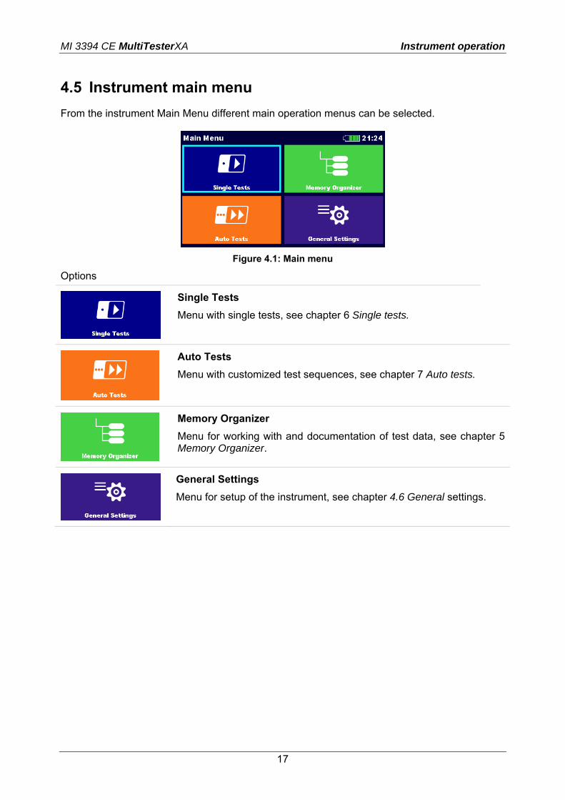
4.5 Instrument main menu
From the instrument Main Menu different main operation menus can be selected.
Figure 4.1: Main menu
Options
Single Tests
Menu with single tests, see chapter 6 Single tests.
Auto Tests
Menu with customized test sequences, see chapter 7 Auto tests.
Memory Organizer
Menu for working with and documentation of test data, see chapter 5 Memory Organizer.
General Settings
Menu for setup of the instrument, see chapter 4.6 General settings.

MI 3394 CE MultiTesterXA Instrument operation
18
4.6 General settings
In the General Settings menu general parameters and settings of the instrument can be viewed or set.
Figure 4.2: Setup menu
Options in General Settings menu
Language
Instrument language selection
Date / Time
Instruments Date and time.
Workspace Manager
Manipulation with project files. Refer to chapter 0
Workspace Manager for more information.
Auto test groups
Manipulation with lists of Auto tests. Refer to chapter 4.9 Auto test groups for more information.
Profiles
Selection of available instrument profiles.
Settings
Setting of different system parameters.
Change password
Changing password for enabling HV tests.
Initial Settings
Factory settings.

MI 3394 CE MultiTesterXA Instrument operation
19
About
Instrument info.
4.6.1 Language In this menu the language of the instrument can be set.
Figure 4.3: Select language menu
4.6.2 Date and time In this menu date and time of the instrument can be set.
Figure 4.4: Setting data and time menu
4.6.3 Profiles Refer to Chapter 4.7 Instrument profiles for more information.
4.6.4 Workspace Manager Refer to Chapter 0 Workspace Manager for more information.
4.6.5 Auto test groups Refer to Chapter 4.9 Auto test groups for more information.
MI 3394 CE MultiTesterXA Instrument operation
20
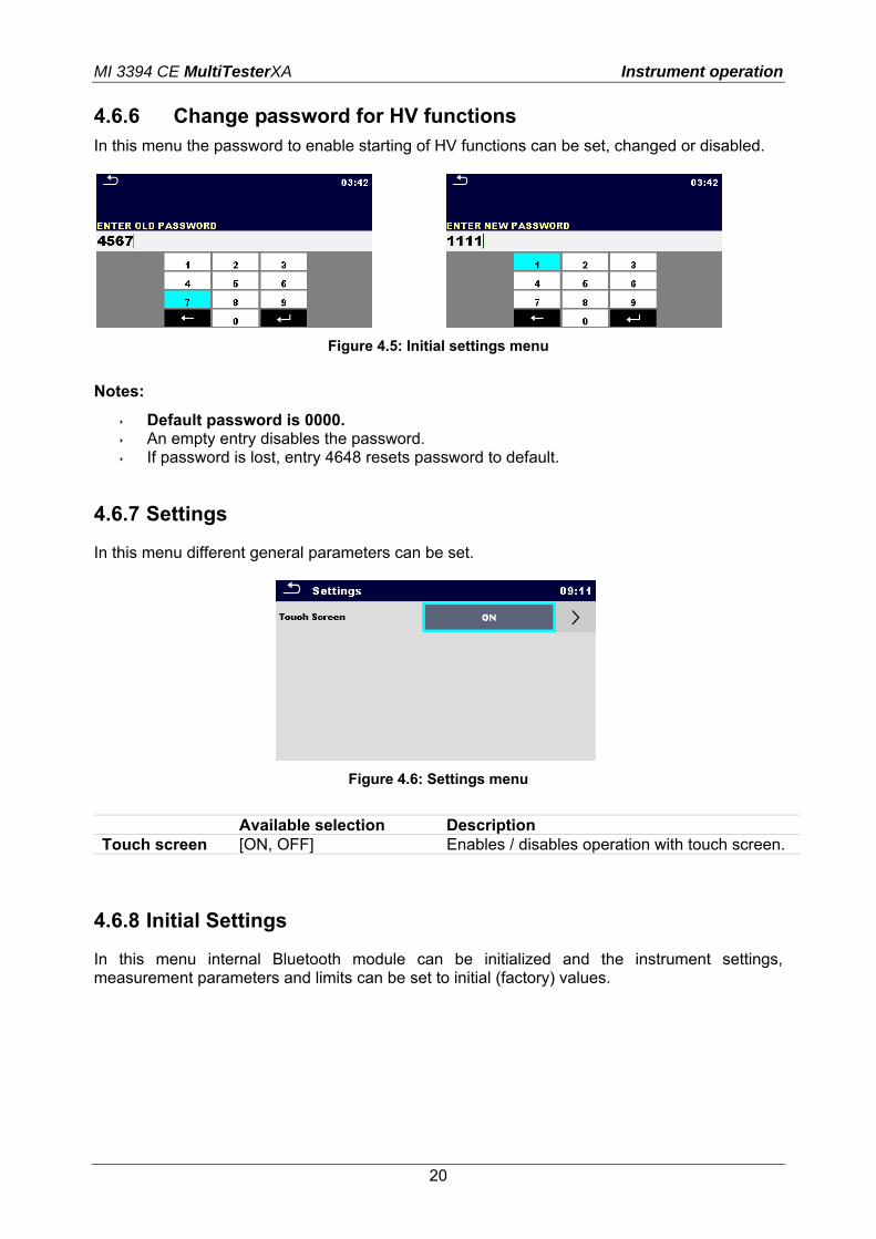
4.6.6 Change password for HV functions In this menu the password to enable starting of HV functions can be set, changed or disabled.
Figure 4.5: Initial settings menu
Notes:
Default password is 0000. An empty entry disables the password. If password is lost, entry 4648 resets password to default.
4.6.7 Settings
In this menu different general parameters can be set.
Figure 4.6: Settings menu
Available selection Description Touch screen [ON, OFF] Enables / disables operation with touch screen.
4.6.8 Initial Settings
In this menu internal Bluetooth module can be initialized and the instrument settings, measurement parameters and limits can be set to initial (factory) values.

MI 3394 CE MultiTesterXA Instrument operation
21
Figure 4.7: Initial settins menu
Warning!
Following customized settings will be lost when setting the instruments to initial settings: Measurement limits and parameters Global parameters and System settings in General settings menu
Note:
Following customized settings will stay: Profile settings Data in memory Password for HV functions
4.6.9 About
In this menu instrument data (name, serial number, version and date of calibration) can be viewed.
Figure 4.8: Instrument info screen
4.7 Instrument profiles
In this menu the instrument profile can be selected from the available ones.

MI 3394 CE MultiTesterXA Instrument operation
22
1
Figure 4.9: Instrument profile menu
The instrument uses different specific system and measuring settings in regard to the scope of work or country it is used. These specific settings are stored in instrument profiles. By default each instrument has at least one profile activated. Proper licence keys must be obtained to add more profiles to the instruments. If different profiles are available they can be selected in this menu. Refer to Appendix B - Profile Notes for more information about functions specified by profiles. Options
Loads the selected profile. The instrument will restart automatically with new profile loaded.
Enters option for deleting a profile
Before deleting the selected profile user is asked for confirmation.
Loaded profiles can’t be deleted.
4.8 Workspace Manager
The Workspace Manager is intended to manage with different Workspaces and Exports stored on the microSD card.
4.8.1 Workspaces and Exports The works with CE MultiTesterXA MI 3394 can be organized with help of Workspaces and Exports. Exports and Workspaces contain all relevant data (measurements, parameters, limits, structure objects) of an individual work.
MI 3394 CE MultiTesterXA Instrument operation
23
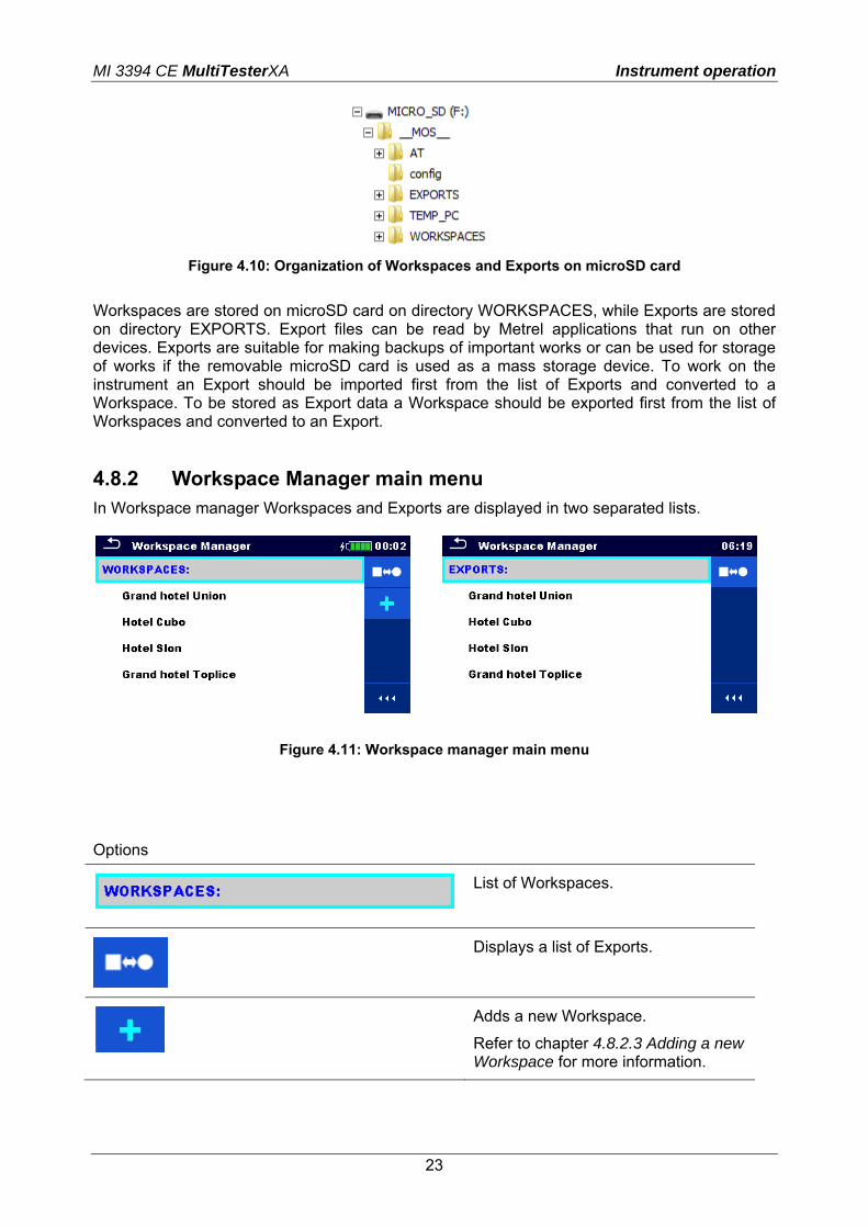
Figure 4.10: Organization of Workspaces and Exports on microSD card
Workspaces are stored on microSD card on directory WORKSPACES, while Exports are stored on directory EXPORTS. Export files can be read by Metrel applications that run on other devices. Exports are suitable for making backups of important works or can be used for storage of works if the removable microSD card is used as a mass storage device. To work on the instrument an Export should be imported first from the list of Exports and converted to a Workspace. To be stored as Export data a Workspace should be exported first from the list of Workspaces and converted to an Export.
4.8.2 Workspace Manager main menu In Workspace manager Workspaces and Exports are displayed in two separated lists.
Figure 4.11: Workspace manager main menu
Options
List of Workspaces.
Displays a list of Exports.
Adds a new Workspace.
Refer to chapter 4.8.2.3 Adding a new Workspace for more information.

MI 3394 CE MultiTesterXA Instrument operation
24
List of Exports.
Displays a list of Workspaces.
4.8.2.1 Operations with Workspaces Only one Workspace can be opened in the instrument at the same time. The Workspace selected in the Workspace Manager will be opened in the Memory Organizer.
Figure 4.12: Workspaces menu
Options
Marks the opened Workspace in Memory Organizer.
Opens the selected Workspace in Memory Organizer.
Refer to chapters 5 Memory Organizer and 4.8.2.4 Opening a Workspace for more information.
Deletes the selected Workspace.
Refer to chapter 4.8.2.5 Deleting a Workspace / Export for more information.
Adds a new Workspace.
Refer to chapter 4.8.2.3 Adding a new Workspace for more information.
Exports a Workspace to an Export
Refer to chapter 4.8.2.7 Exporting a Workspace for more information.
Opens options in control panel / expands column.
4.8.2.2 Operations with Exports

MI 3394 CE MultiTesterXA Instrument operation
25
Figure 4.13: Workspace manager Exports menu
Options
Deletes the selected Export.
Refer to chapter 4.8.2.5 Deleting a Workspace / Export for more information.
Imports a new Workspace from Export.
Refer to chapter 4.8.2.6 Importing a Workspace for more information.
Opens options in control panel / expands column.
4.8.2.3 Adding a new Workspace
New workspaces can be added from the Workspace manager screen.
Enters option for adding a new Workspace.
Keypad for entering name of a new Workspace is displayed after selecting New.

MI 3394 CE MultiTesterXA Instrument operation
26
After confirmation a new Workspace is added to the list of workspaces.
4.8.2.4 Opening a Workspace
Workspace can be selected from a list in Workspace manager screen.
Opens a Workspace in Workspace manager.
The opened Workspace is marked with a blue dot. The previously opened Workspace will close automatically.
4.8.2.5 Deleting a Workspace / Export
Workspace / Export to be deleted should be selected from the list of Workspaces / Exports.

MI 3394 CE MultiTesterXA Instrument operation
27
Enters option for deleting a Workspace / Export.
Before deleting the selected Workspace / Export the user is asked for confirmation.
Workspace / Export is deleted from the Workspace / Export list.
4.8.2.6 Importing a Workspace
Select an Export file to be imported from Workspace manager Export list.
Enters option Import.
Before the import of the selected Export file the user is asked for confirmation.

MI 3394 CE MultiTesterXA Instrument operation
28
The imported Export file is added to the list of Workspaces.
Note: If a Workspace with the same name already exists the name of the imported Workspace will be changed (name_001, name_002, name_003, …).
4.8.2.7 Exporting a Workspace
Select a Workspace from Workspace manager list to be exported to an Export file.
Enters option for Export.
Before exporting the selected Workspace the user is asked for confirmation.
Workspace is exported to Export file and is added to the list of Exports.
Note: If an Export file with the same name already exists the name of the an Export file will be changed (name_001, name_002, name_003, …).

MI 3394 CE MultiTesterXA Instrument operation
29
4.9 Auto test groups
The Auto tests in CE MultiTesterXA MI 3394 can be organized in lists of Auto tests. In a list a group of similar Auto tests is stored. The Auto test groups menu is intended to manage with different lists of Auto tests that are stored on the microSD card.
Figure 4.14: Organization of Auto tests on microSD card
Directories with lists of Auto tests are stored in Root\__MOS__\AT on the microSD card.
4.9.1 Auto test groups menu In Auto test groups menu lists of Auto tests are displayed. Only one list can be opened in the instrument at the same time. The list selected in the Auto test groups menu will be opened in the Auto Tests main menu.
Figure 4.15: Auto test groups menu
4.9.1.1 Operations in Auto test groups menu: Options

MI 3394 CE MultiTesterXA Instrument operation
30
Opens the selected list of Auto tests. Previously selected list of Auto tests will be closed automatically.
Refer to chapter 4.9.1.2 Selecting a list of Auto tests for more information.
Deletes the selected list of Auto tests.
Refer to chapter 4.9.1.3 Deleting a list of Auto tests for more information.
Opens options in control panel / expands column.
4.9.1.2 Selecting a list of Auto tests
A list of Auto tests can be selected from the Auto test groups menu.
Enters option for selecting a list.
Selected list of Auto tests is marked with a blue dot.
Note:
Previously selected list of Auto tests is closed automatically.
4.9.1.3 Deleting a list of Auto tests
A list of Auto tests to be deleted can be selected from the Auto test groups menu.

MI 3394 CE MultiTesterXA Instrument operation
31
Enters option for deleting a list.
Before deleting the selected list of Auto tests the user is asked for confirmation.
A list of Auto tests is deleted.

MI 3394 CE MultiTesterXA Memory Organizer
32
5 Memory Organizer Memory Organizer is a tool for storing and working with test data.
5.1 Memory Organizer menu
The data is organized in a tree structure with Structure objects and Measurements. CE MultiTesterXA has a fixed three level structure. The hierarchy of Structure objects in the tree is shown on Figure 5.1. 0th level 1st level 2nd level 3rd level
NODE
APPLIANCE FD (full description)
measurement
APPLIANCE (short description)
measurement
PROJECT
APPLIANCE FD
measurement
APPLIANCE
measurement
LOCATION
APPLIANCE FD
measurement
APPLIANCE
measurement
Figure 5.1: Tree structure and its hierarchy

MI 3394 CE MultiTesterXA Memory Organizer
33
Figure 5.2: Example of a Tree menu
5.1.1 Measurement statuses Each measurement has:
a status (Pass or Fail or no status) a name results limits and parameters
A measurement can be a Single test or an Auto test. Statuses of single tests:
passed finished single test with test results
failed finished single test with test results
finished single test with test results and no status
empty single test without test results Overall statuses of Auto tests:
at least one single test in the Auto test passed and no single test failed
at least one single test in the Auto test failed
at least one single test in the Auto test was carried out and there were no other passed or failed single tests.
empty Auto test with empty single tests
5.1.2 Structure Objects Each Structure object has:
an icon a name parameters
Optionally they can have: an indication of the status of the measurements under the Structure object a comment or a file attached
Structure objects supported in CE MultitesterXA are described in Appendix A - Structure objects in CE MultiTesterXA.

MI 3394 CE MultiTesterXA Memory Organizer
34
Figure 5.3: Structure object in tree menu
5.1.2.1 Measurement status indication under the Structure object Overall status of measurements under each structure element / sub-element can be seen without spreading tree menu. This feature is useful for quick evaluation of test status and as guidance for measurements. Options
There are no measurement result(s) under selected structure object. Measurements should be made.
Figure 5.4: Example of status - No measurement result(s)
One or more measurement result(s) under selected structure object has failed. Not all measurements under selected structure object have been made yet.
Figure 5.5: Example of status - Measurements not completed with fail
result(s)
All measurements under selected structure object are completed but one or more measurement result(s) has failed.
Figure 5.6: Status - Measurements completed with fail result(s)
Note:
There is no status indication if all measurement results under each structure element / sub-element have passed or if there is an empty structure element / sub-element (without measurements).

MI 3394 CE MultiTesterXA Memory Organizer
35
5.1.3 Operations in Tree menu In the Memory organizer different actions can be taken with help of the control panel at the right side of the display. Possible actions depend on the selected element in the organizer. 5.1.3.1 Operations on measurements (finished or empty measurements)
Figure 5.7: A measurement is selected in the Tree menu
Options
Views results of measurement.
The instrument goes to the measurement memory screen. Refer to chapters 6.1.6 Single test memory screen and 7.2.3 Auto test memory screen for more information.
Starts a new measurement.
The instrument goes to the measurement start screen. Refer to chapters 6.1.3 Single test start screen and 7.2.1 Auto test view menu for more information.
Saves a measurement.
Saving of measurement on a position after the selected (empty or finished) measurement.
Clones the measurement.
The selected measurement can be copied as an empty measurement under the same Structure object. Refer to chapter 5.1.3.7 Clone a measurement for more information.
Copies & Paste a measurement.
The selected measurement can be copied and pasted as an empty measurement to any location in structure tree. Multiple “Paste” is allowed. Refer to chapter 5.1.3.9 Copy & Paste a measurement for more information.
Adds a new measurement.
The instrument goes to the Menu for adding measurements. Refer to chapter 5.1.3.5 Add a new measurement for more information.

MI 3394 CE MultiTesterXA Memory Organizer
36
deletes a measurement.
Selected Measurement can be deleted. User is asked for confirmation before the deleting. Refer to chapter 5.1.3.11 Delete a measurement for more information.
5.1.3.2 Operations on Structure objects The structure object must be selected first.
Figure 5.8: A structure object is selected in the tree menu
Options
Starts a new measurement.
First type of measurement (single test or Auto test) should be selected. After proper type is selected the instrument goes to single test or Auto test selection screen. Refer to chapters 6.1 Selection of single tests and 7.1 Selection of Auto tests.
Saves a measurement.
Saving of measurement under the selected Structure object.
View / edit parameters and attachments.
Parameters and attachments of the Structure object can be viewed or edited. Refer to chapter 5.1.3.3 View / Edit parameters and attachments of a Structure object for more information.
Adds a new measurement.
The instrument goes to the Menu for adding measurement into structure. Refer to chapter 5.1.3.5 Add a new measurement for more information.
Adds a new Structure object.
A new Structure object can be added. Refer to chapter 5.1.3.4 Add a new Structure Object for more information.
Attachments.
Name and link of attachment is displayed.

MI 3394 CE MultiTesterXA Memory Organizer
37
Clones a Structure object.
Selected Structure object can be copied to same level in structure tree (clone). Refer to chapter 5.1.3.6 Clone a Structure object for more information.
Copies & Paste a Structure object.
Selected Structure object can be copied and pasted to any allowed location in structure tree. Multiple “Paste” is allowed. Refer to chapter 5.1.3.8 Copy & Paste a Structure object for more information.
Deletes a Structure object.
Selected Structure object and sub-elements can be deleted. User is asked for confirmation before the deleting. Refer to chapter 5.1.3.10 Delete a Structure object for more information.
Renames a Structure object.
Selected Structure object can be renamed via keypad. Refer to chapter 5.1.3.12 Rename a Structure object for more information.
Expands column in control panel.
5.1.3.3 View / Edit parameters and attachments of a Structure object
The parameters and their content are displayed in this menu. To edit the selected parameter tap on it or press Enter key to enter menu for editing parameters.
Parameters
Figure 5.9: Example of View / Edit parameters menu
In menu for editing parameters the parameter’s value can be selected from a dropdown list or entered via keypad. Refer to chapter 4 Instrument operation for more information about keypad operation.

MI 3394 CE MultiTesterXA Memory Organizer
38
Attachments
The name of attachment can be seen. Operation with attachments is not supported in the instrument.
5.1.3.4 Add a new Structure Object This menu is intended to add new structure objects in the tree menu. A new structure object can be selected and then added in the tree menu.
Add Structure
Figure 5.10: Add a new Structure Object menu
The type of Structure object to be added can be selected from dropdown menu.
Only structure objects that can be used in the same level or next sublevel are offered.
The name of the Structure object can be edited.

MI 3394 CE MultiTesterXA Memory Organizer
39
Parameters of the Structure object can be edited.
Adds the selected structure object and its parameters in the tree menu.
Returns to the tree menu without changes.
5.1.3.5 Add a new measurement In this menu new empty measurements can be set and then added in the structure tree. The type of measurement, measurement function and its parameters are first selected and then added under the selected Structure object.
Add Measurement

MI 3394 CE MultiTesterXA Memory Organizer
40
Figure 5.11: Add a new measurement menu
Type of test can be selected from this field.
Options: (Single tests, Auto tests)
Tap on field or press ENTER key to modify.
Last added measurement is offered by default. To select another measurement press Enter to open menu for selecting measurements. Refer to chapters 6.1 Selection of single tests and 7.1 Selection of Auto tests for more information,
Tap on field or press ENTER key to open menu for editing parameters of the selected measurement.
Select parameter and modify it as described earlier.
Refer to chapter 6.1.2 Setting parameters and limits of single tests for more information.
Add a new empty measurement.
Adds the measurement under the selected Structure object in the tree menu.
Returns to the structure tree menu without changes.
5.1.3.6 Clone a Structure object In this menu selected structure object can be copied (cloned) to same level in the structure tree. Cloned structure object have same name as original.
Clone
Figure 5.12: Clone Structure Object menu
MI 3394 CE MultiTesterXA Memory Organizer
41
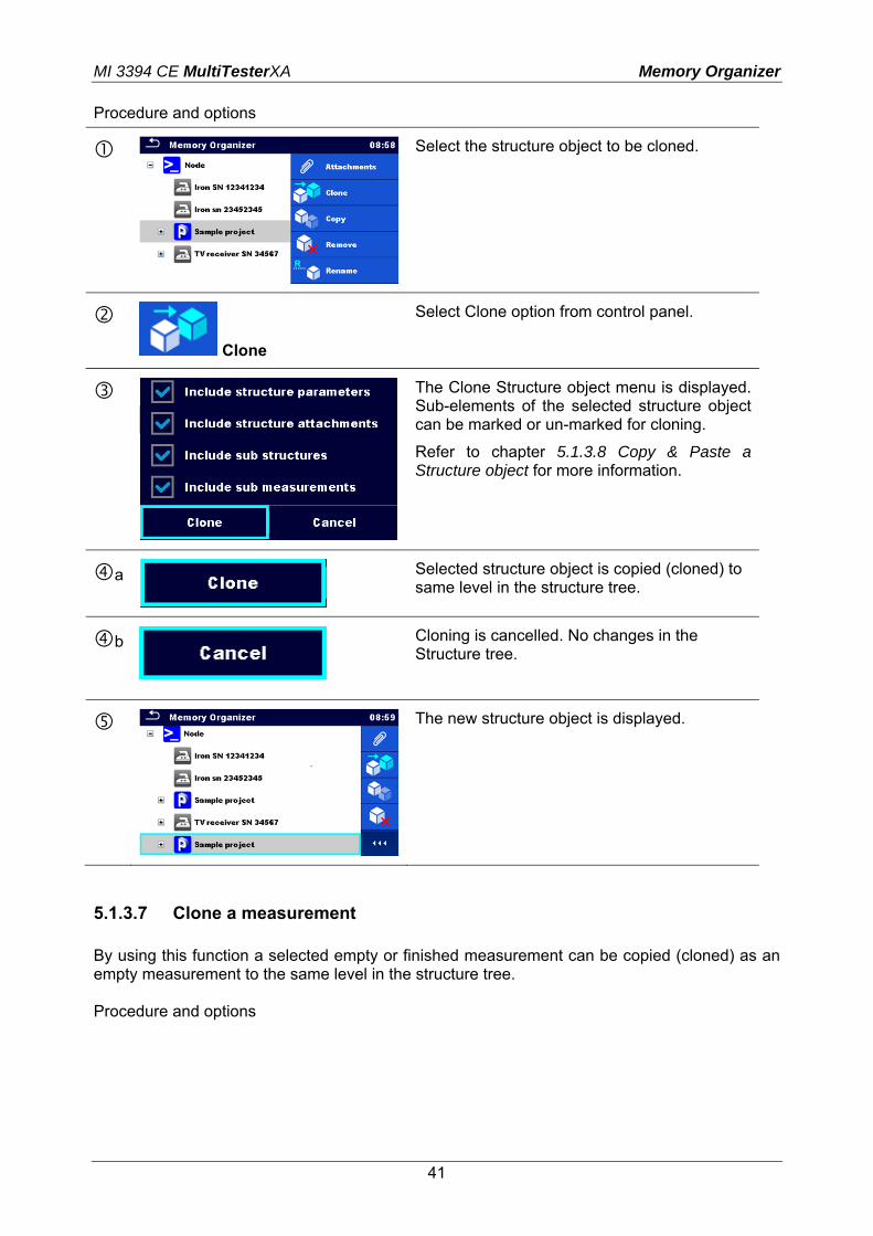
Procedure and options
Select the structure object to be cloned.
Clone
Select Clone option from control panel.
The Clone Structure object menu is displayed. Sub-elements of the selected structure object can be marked or un-marked for cloning.
Refer to chapter 5.1.3.8 Copy & Paste a Structure object for more information.
a
Selected structure object is copied (cloned) to same level in the structure tree.
b
Cloning is cancelled. No changes in the Structure tree.
The new structure object is displayed.
5.1.3.7 Clone a measurement By using this function a selected empty or finished measurement can be copied (cloned) as an empty measurement to the same level in the structure tree. Procedure and options

MI 3394 CE MultiTesterXA Memory Organizer
42
Select the measurement to be cloned.
Clone
Select Clone option from control panel.
The new empty measurement is displayed.
5.1.3.8 Copy & Paste a Structure object In this menu selected Structure object can be copied and pasted to any allowed location in the structure tree. Procedure and options
Select the structure object to be copied.
Copy
Select Copy option from control panel.
Select location where structure element should be copied.

MI 3394 CE MultiTesterXA Memory Organizer
43
Paste
Select Paste option from control panel.
The Paste structure object menu is displayed. Before copying it can be set which sub-elements of the selected structure object will be copied too. For more details see options below.
a
The selected structure object and elements are copied (pasted) to selected position in the tree structure.
b
Returns to the tree menu without changes.
The new structure object is displayed.
Note:
The Paste command can be executed one or more times.
Options
Parameters of selected structure object will be copied too.
Attachments of selected structure object will be copied too.
Structure objects in sub-levels of selected structure object will be copied too.
Measurements in selected structure object and sub-levels will be copied too.
5.1.3.9 Copy & Paste a measurement
In this menu selected measurement can be copied to any allowed location in the structure tree. Procedure

MI 3394 CE MultiTesterXA Memory Organizer
44
Select the structure object to be copied.
Copy
Select Copy option from control panel.
Select location where structure element should be copied.
Paste
Select Paste option from control panel.
The new (empty) measurement is displayed in selected Structure object.
5.1.3.10 Delete a Structure object In this menu selected Structure object can be deleted. Procedure
Select the structure object to be deleted.

MI 3394 CE MultiTesterXA Memory Organizer
45
Delete
Select Delete option from control panel.
A confirmation window will appear.
a
Selected structure object and its sub-elements are deleted.
b
Returns to the tree menu without changes.
5.1.3.11 Delete a measurement
In this menu selected measurement can be deleted. Procedure
Select a measurement to be deleted.
Delete
Select Delete option from control panel.
A confirmation window will appear.
a
Selected measurement is deleted.

MI 3394 CE MultiTesterXA Memory Organizer
46
b
Returns to the tree menu without changes.
5.1.3.12 Rename a Structure object In this menu selected Structure object can be renamed. Procedure
Select the structure object to be renamed.
Rename
Select Rename option from control panel.
Virtual keypad will appear on screen. Enter new text and confirm.

MI 3394 CE MultiTesterXA Single tests
47
6 Single tests
6.1 Selection of single tests
Single tests can be selected in the Main single test menu or in Memory Organizer’s main and submenus. In Single test main menu there are four modes for selecting single tests. Options
All
A single test can be selected from a list of all single tests. The single tests are always displayed in the same (default) order.
Last used
Last 9 made different single tests are displayed.
Groups
The single tests are divided into groups of similar tests.

MI 3394 CE MultiTesterXA Single tests
48
For the selected group a submenu with all single tests that belongs to the selected group is displayed.
Cross selector
This selection mode is the fastest way for working with the keypad. Groups of single tests are organized in a row.
For the selected group all single tests are displayed and accessible with up/down keys.
Opens options in control panel / expands column.
6.1.1 Single test screens In the Single test screens measuring results, sub-results, limits and parameters of the measurement are displayed. In addition on-line statuses, warnings and other information are displayed.

MI 3394 CE MultiTesterXA Single tests
49
Figure 6.1: Single test screen organisation
6.1.2 Setting parameters and limits of single tests
Figure 6.2: Screens in menu for setting Single test parameters and limits
Selects parameter (white) or limit (red).
Selects value of parameter or limit.
In case of many (multiple pages of) parameters or limits: - The scroll bar on the right side of screen can be used - With right / left keys it can be jumped page up / page
down

MI 3394 CE MultiTesterXA Single tests
50
6.1.3 Single test start screen
Figure 6.3: Single test start screen
Options (before test, screen was opened in Memory organizer or from Single test main menu)
Starts the measurement.
Opens help screens. Refer to chapter 6.1.7 Help screens for more information.
on
Opens menu for changing parameters and limits.
Refer to chapter 6.1.2 Setting parameters and limits of single tests for more information.
long on
Enters cross selector. Refer to chapter 6.1 Selection of single tests for more information.
Opens options in control panel / expands column.

MI 3394 CE MultiTesterXA Single tests
51
6.1.4 Single test screen during test
Figure 6.4: Single test screen (during measurement)
Options (during test)
Stops the single test measurement.
Proceeds to the next step of the measurement (if measurement consists of more steps).
Aborts measurements.
6.1.5 Single test result screen
Figure 6.5: Single test result screen
Options (after measurement is finished)
Starts a new measurement.

MI 3394 CE MultiTesterXA Single tests
52
Saves the result.
A new measurement was selected and started from a Structure object in the structure tree:
- The measurement will be saved under the selected Structure object.
A new measurement was started from the Single test main menu:
- Saving under the last selected Structure object will be offered by default. The user can select another Structure object or create a
new Structure object. By pressing the key in Memory organizer menu the measurement is saved under selected location.
An empty measurement was selected in structure tree and started:
- The result(s) will be added to the measurement. The measurement will change its status from ‘empty’ to ‘finished’.
An already carried out measurement was selected in structure tree, viewed and then restarted:
- A new measurement will be saved under the selected Structure object.
Opens help screens. Refer to chapter 6.1.7 Help screens for more information.
on
Opens screen for changing parameters and limits.
Refer to chapter 6.1.2 Setting parameters and limits of single tests for more information.
long on
Enters cross selector. Refer to chapter 6.1 Selection of single tests for more information.
Opens options in control panel / expands column.

MI 3394 CE MultiTesterXA Single tests
53
6.1.6 Single test memory screen
Figure 6.6: Single test memory screen
Options
Retest
Enters screen with “empty” measurement.
on
Opens menu for viewing parameters and limits.
Refer to chapter 6.1.2 Setting parameters and limits of single tests for more information.
6.1.7 Help screens Help screens contain diagrams for proper connection of the instrument.
Figure 6.7: Examples of help screens
Options
on
Goes to previous / next help screen.

MI 3394 CE MultiTesterXA Single tests
54
6.2 Single test measurements
6.2.1 Continuity
Figure 6.8: Continuity test menu
Test results / sub-results
R ............... Resistance
Test parameters
Output connections Output [4-wire, P-PE] Test current I out [0.2 A, 4 A, 10 A, 25 A] Duration Duration [Off, 2 s ... 180 s]
Test limits
H Limit (R) H limit [Off, 0.01 Ω ... 9 Ω ] L Limit (R) L limit [Off, 0.01 Ω ... 9 Ω ] Test circuit
Figure 6.9: Measurement of continuity 4-wire

MI 3394 CE MultiTesterXA Single tests
55
Figure 6.10: Measurement of Continuity P/S - PE
Continuity measurement procedure
Select the Continuity function. Set test parameters / limits. Connect test leads to C1, P1, P2 and C2 terminals on the instrument (4 wire), or connect
test lead to P/S terminal (2 wire measurement P/S – PE). Connect test leads to device under test. Start measurement. Measurement can be stopped manually or by timer. Save results (optional).
Figure 6.11: Examples of Continuity measurement results
6.2.2 HV AC
IMPORTANT SAFETY NOTE
Refer to chapter 1.1 Warnings and notes for more information regarding safe use of the instrument.

MI 3394 CE MultiTesterXA Single tests
56
Figure 6.12: HV AC test menu
Test results / sub-results
I ................. test current U ............... measured a.c. test voltage Ir ............... resistive portion of test current Ic ............... capacitive portion of test current
Test parameters
AC test voltage U test [100 V ... 5000 V in steps of 10 V] Duration t end [Off, 1 s ... 120 s]
Test limits
High limit (I) H limit [0.5 mA ... 100 mA ] Low limit (I) L limit [Off, 0.5 mA ... 100 mA]
Test circuit
Figure 6.13: HV AC measurement
HV AC measurement procedure
Select the HV AC function. Set test parameters / limits. Connect HV test leads to HV(~,+) and HV(~,-) terminals on the instrument. Connect HV test leads to device under test.

MI 3394 CE MultiTesterXA Single tests
57
Start measurement. Measurement can be stopped manually or by timer. Save results (optional).
Figure 6.14: Examples of HV AC meaasurement results
Note:
First HV measurement after power on the instrument (if password protection is enabled) or first HV measurement after enabling or changing password require entering password for enabling HV test. Refer to chapter 4.6.6 Change password for HV functions for more information.
6.2.3 HV DC
IMPORTANT SAFETY NOTE
Refer to chapter 1.1 Warnings and notes for more information regarding safe use of the instrument.
Figure 6.15: HV DC test menu

MI 3394 CE MultiTesterXA Single tests
58
Test results / sub-results
U ............... measured test voltage I ................. test current
Test parameters
DC test voltage U test [500 V ... 6000 V in steps of 50 V] Duration t end [Off, 1 s ... 120 s]
Test limits
High limit (I) H limit [0.05 mA ... 10.0 mA ] Low limit (I) L limit [Off, 0.05 mA ... 10.0 mA]
Test circuit
Figure 6.16: HV DC measurement
HV DC measurement procedure
Select the HV DC function. Set test parameters / limits. Connect HV test leads to HV(~,+) and HV(~,-) terminals on the instrument. Connect HV test leads to device under test. Start measurement. Measurement can be stopped manually or by timer. Save results (optional).

MI 3394 CE MultiTesterXA Single tests
59
Figure 6.17: Examples of HV DC measurement results
Note:
First HV measurement after power on the instrument (if password protection is enabled) or first HV measurement after enabling or changing password require entering password for enabling HV test. Refer to chapter 4.6.6 Change password for HV functions for more information.
6.2.4 HV AC programmable
IMPORTANT SAFETY NOTE
Refer to chapter 1.1 Warnings and notes for more information regarding safe use of the instrument. In the HV AC programmable test the time dependency of high voltage can be set according to diagram on Figure 6.18.
Figure 6.18: Voltage / time diagram of the HV AC programmable test

MI 3394 CE MultiTesterXA Single tests
60
Figure 6.19: HV AC programmable test menu
Test results / sub-results
I ................. test current U ............... measured test voltage Ir ............... resistive portion of test current Ic ............... capacitive portion of test current
Test parameters
Starting AC test voltage U start [100 V ... 5000 V in steps of 10 V] AC test voltage U test [100 V ... 5000 V in steps of 10 V] Duration of starting voltage t start [1 s ... 120 s ] Duration of ramp t ramp [2 s ... 60 s ] Duration of test voltage t end [Off, 1 s ... 120 s ]
Test limits
High limit (I) H limit [0.5 mA ... 100 mA ] Low limit (I) L limit [Off, 0.5 mA ... 100 mA]
Test circuit
Figure 6.20: HV AC programmable test

MI 3394 CE MultiTesterXA Single tests
61
HV AC programmable test procedure
Select the HV AC programmable function. Set test parameters / limits. Connect HV test leads to HV(~,+) and HV(~,-) terminals on the instrument. Connect HV test leads to device under test. Start measurement. Measurement can be stopped manually or by timer. Save results (optional).
Figure 6.21: Examples of HV AC programmable test results
Note: First HV measurement after power on the instrument (if password protection is enabled)
or first HV measurement after enabling or changing password require entering password for enabling HV test. Refer to chapter 4.6.6 Change password for HV functions for more information.
6.2.5 HV DC programmable
IMPORTANT SAFETY NOTE
Refer to chapter 1.1 Warnings and notes for more information regarding safe use of the instrument.
In the HV DC programmable test the time dependency of high voltage can be set according to diagram on Figure 6.22.
Figure 6.22: HV DC programmable test menu
Test results / sub-results
U ............... measured test voltage I ................. test current

MI 3394 CE MultiTesterXA Single tests
62
Ic ............... capacitive portion of test current Ir ............... resistive portion of test current
Test parameters
Starting DC test voltage U start [500 V ... 6000 V in steps of 50 V] DC test voltage U test [500 V ... 6000 V in steps of 50 V] Duration of starting voltage t start [1 s ... 120 s ] Duration of ramp t ramp [2 s ... 60 s ] Duration of test voltage t end [Off, 1 s ... 120 s ]
Test limits
High limit (I) H limit [0.05 mA ... 10.0 mA ] Low limit (I) L limit [Off, 0.05 mA ... 10.0 mA] Test circuit
Figure 6.23: HV DC programmable test
HV DC programmable test procedure
Select the HV DC programmable function. Set test parameters / limits. Connect HV test leads to HV(~,+) and HV(~,-) terminals on the instrument. Connect HV test leads to device under test. Start measurement. Measurement can be stopped manually or by timer. Save results (optional).

MI 3394 CE MultiTesterXA Single tests
63
Figure 6.24: Examples of HV DC programmable test results
Note:
First HV measurement after power on the instrument (if password protection is enabled) or first HV measurement after enabling or changing password require entering password for enabling HV test. Refer to chapter 4.6.6 Change password for HV functions for more information.
6.2.6 Insulation resistance (Riso, Riso-S)
Figure 6.25: Insulation resistance test menus
Test results / sub-results
Riso .......... Insulation resistance Riso-S ....... Insulation resistance-S Um ............ Test voltage
Test parameters
Nominal test voltage Uiso [50 V, 100 V, 250 V, 500 V, 1000 V] Duration Duration [Off, 2 s ... 180 s] Type of test Type [Riso, Riso-S, (Riso, Riso-S)] Output connections (Riso) [ISO(+), ISO(-), Socket LN-PE, Socket LN-P/S] Output connections (Riso-S) [Socket LN-P/S]
Test limits
H Limit (Riso) H limit [Off, 0.10 MΩ ... 10.0 MΩ ] L Limit (Riso) L limit [Off, 0.10 MΩ ... 10.0 MΩ ] H Limit (Riso-S) H limit [Off, 0.10 MΩ ... 10.0 MΩ ] L Limit (Riso-S) L limit [Off, 0.10 MΩ ... 10.0 MΩ ]
Test circuits

MI 3394 CE MultiTesterXA Single tests
64
Figure 6.26: Measurement of insulation resistance (ISO(+), ISO(-))
Figure 6.27: Measurement of insulation resistance (Socket LN - PE)

MI 3394 CE MultiTesterXA Single tests
65
Figure 6.28: Measurement of Riso, Riso-S (socket)
RISO measurement procedure
Select the Riso function. Set test parameters / limits. Connect test leads to ISO(+), ISO(-) terminals on the instrument, then connect test leads to
device under test, or Connect device to mains test socket. For Riso-S test, additionally connect test lead to P/S
terminal on instrument, and then connect test lead to device. Start measurement. Measurement can be stopped manually or by timer. Save results (optional).
Figure 6.29: Examples of Insulation resistance measurement results
Note: When P/S probe is connected during the Riso measurement, then the current through it
is also considered.
6.2.7 Sub-leakage (Isub, Isub-S)

MI 3394 CE MultiTesterXA Single tests
66
Figure 6.30: Sub Leakage test menus
Test results / sub-results
Isub ........... Sub-leakage current Isub-S ....... Sub-leakage current-S
Test parameters
Type of test Type [Isub, Isub-S, (Isub, Isub-S)] Output voltage Output [40 Vac] Duration Duration [Off, 2 s ... 180 s] Output connections (Isub) [SUB1, SUB2, Socket LN-PE, Socket LN-P/S] Output connections (Isub-S) [Socket LN-P/S]
Test limits
H Limit (Isub) H limit [Off, 0.25 mA ... 15.0 mA ] L Limit (Isub) L limit [Off, 0.25 mA ... 15.0 mA ] H Limit (Isub-S) H limit [Off, 0.25 mA ... 15.0 mA ] L Limit (Isub-S) L limit [Off, 0.25 mA ... 15.0 mA ]
Test circuits

MI 3394 CE MultiTesterXA Single tests
67
Figure 6.31: Measurement of Sub-leakage (SUB1, SUB2)
Figure 6.32: Measurement of Sub-leakage (socket LN-PE)
Figure 6.33: Measurement of Sub-leakage, Sub-leakage-S (socket)
MI 3394 CE MultiTesterXA Single tests
68
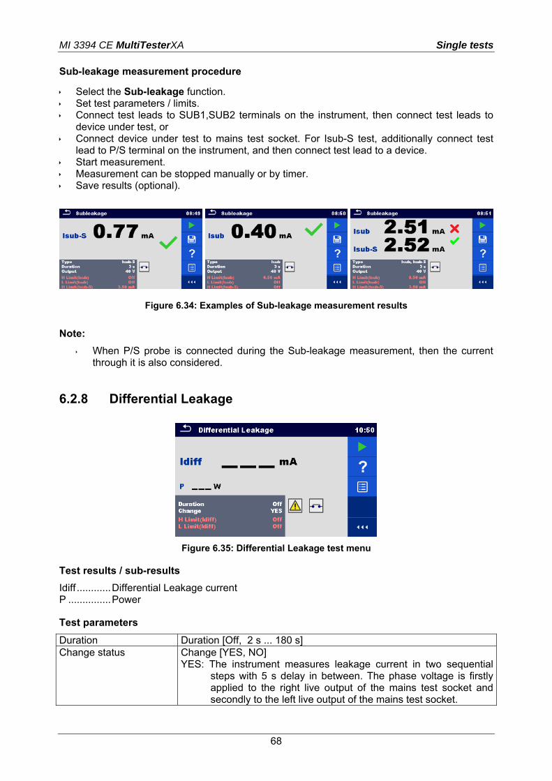
Sub-leakage measurement procedure
Select the Sub-leakage function. Set test parameters / limits. Connect test leads to SUB1,SUB2 terminals on the instrument, then connect test leads to
device under test, or Connect device under test to mains test socket. For Isub-S test, additionally connect test
lead to P/S terminal on the instrument, and then connect test lead to a device. Start measurement. Measurement can be stopped manually or by timer. Save results (optional).
Figure 6.34: Examples of Sub-leakage measurement results
Note:
When P/S probe is connected during the Sub-leakage measurement, then the current through it is also considered.
6.2.8 Differential Leakage
Figure 6.35: Differential Leakage test menu
Test results / sub-results
Idiff ............ Differential Leakage current P ............... Power
Test parameters
Duration Duration [Off, 2 s ... 180 s] Change status Change [YES, NO]
YES: The instrument measures leakage current in two sequential steps with 5 s delay in between. The phase voltage is firstly applied to the right live output of the mains test socket and secondly to the left live output of the mains test socket.

MI 3394 CE MultiTesterXA Single tests
69
NO: The phase voltage is applied only to the right live output of the mains test socket.
Test limits
H Limit (Idiff) H limit [Off, 0.25 mA ... 15.0 mA ] L Limit (Idiff) L limit [Off, 0.25 mA ... 15.0 mA ] Output connections [Socket L,N – PE,P/S]
Test circuit
Figure 6.36: Measurement of Differential Leakage current
Differential Leakage measurement procedure
Select the Differential Leakage function. Set test parameters / limits. Connect device under test to mains test socket and optionally to P/S terminal. Start measurement. Measurement can be stopped manually or by timer. Save results (optional).
Figure 6.37: Examples of Differential Leakage measurement results

MI 3394 CE MultiTesterXA Single tests
70
6.2.9 Ipe Leakage
Figure 6.38: Ipe Leakage test menu
Test results / sub-results
Ipe ............. PE current P ............... Power
Test parameters
Duration Duration [Off, 2 s ... 180 s] Change status Change [YES, NO]
YES: The instrument measures leakage current in two sequential steps with 5 s delay in between. The phase voltage is firstly applied to the right live output of the mains test socket and secondly to the left live output of the mains test socket.
NO: The phase voltage is applied only to the right live output of the mains test socket.
Output connections [Socket L,N – PE]
Test limits
H Limit (Ipe) H limit [Off, 0.25 mA ... 15.0 mA ] L Limit (Ipe) L limit [Off, 0.25 mA ... 15.0 mA ] Test circuit
Figure 6.39: Measurement of Ipe Leakage current

MI 3394 CE MultiTesterXA Single tests
71
Ipe Leakage measurement procedure
Select the Ipe Leakage function. Set test parameters / limits. Connect device under test to mains test socket. Start measurement. Measurement can be stopped manually or by timer. Save results (optional).
Figure 6.40: Examples of Ipe Leakage measurement results
6.2.10 Touch Leakage
Figure 6.41: Touch Leakage test menu
Test results / sub-results
Itou ............ Touch Leakage current P ............... Power
Test parameters
Duration Duration [Off, 2 s ... 180 s] Change status Change [YES, NO]
YES: The instrument measures leakage current in two sequential steps with 5 s delay in between. The phase voltage is firstly applied to the right live output of the mains test socket and secondly to the left live output of the mains test socket.
NO: The phase voltage is applied only to the right live output of the mains test socket.
Output connections [Socket L,N – PE,P/S]

MI 3394 CE MultiTesterXA Single tests
72
Test limits
H Limit (Itou) H limit [Off, 0.25 mA ... 15.0 mA ] L Limit (Itou) L limit [Off, 0.25 mA ... 15.0 mA ] Test circuit
Figure 6.42: Measurement of Touch Leakage current
Touch Leakage measurement procedure
Select the Touch Leakage function. Set test parameters / limits. Connect device under test to mains test socket. Connect test lead to P/S terminal on the
instrument and on device under test. Start measurement. Measurement can be stopped manually or by timer. Save results (optional).
Figure 6.43: Examples of Touch Leakage measurement results
MI 3394 CE MultiTesterXA Single tests
73
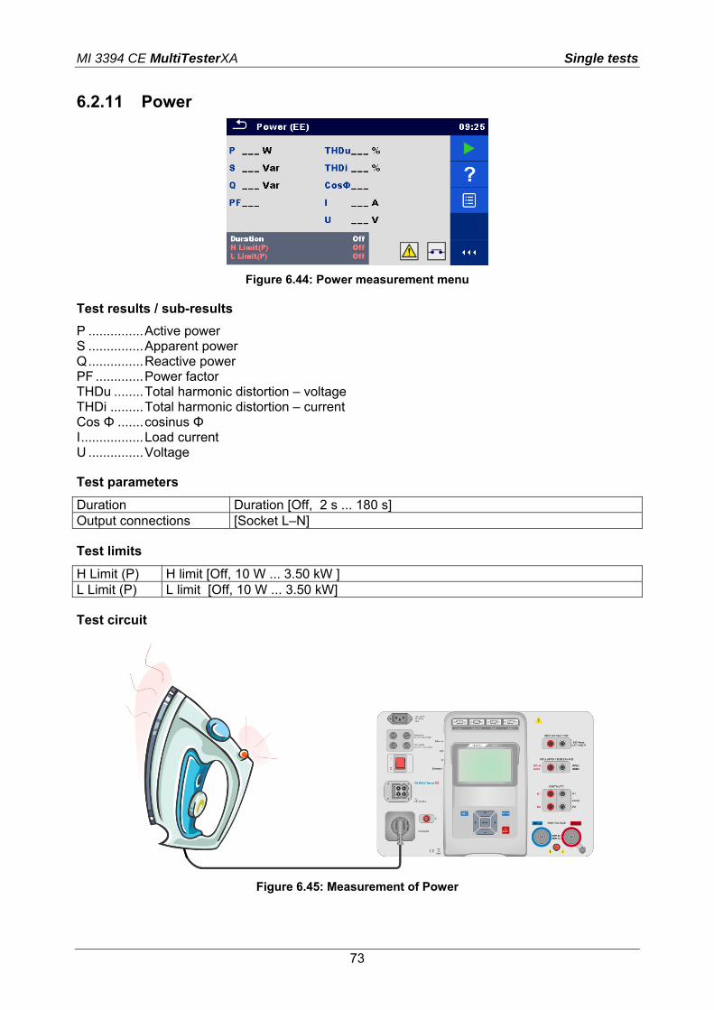
6.2.11 Power
Figure 6.44: Power measurement menu
Test results / sub-results
P ............... Active power S ............... Apparent power Q ............... Reactive power PF ............. Power factor THDu ........ Total harmonic distortion – voltage THDi ......... Total harmonic distortion – current Cos Φ ....... cosinus Φ I ................. Load current U ............... Voltage
Test parameters
Duration Duration [Off, 2 s ... 180 s] Output connections [Socket L–N]
Test limits
H Limit (P) H limit [Off, 10 W ... 3.50 kW ] L Limit (P) L limit [Off, 10 W ... 3.50 kW]
Test circuit
Figure 6.45: Measurement of Power

MI 3394 CE MultiTesterXA Single tests
74
Power measurement procedure
Select the Power function. Set test parameters / limits. Connect device under test to mains test socket. Start measurement. Measurement can be stopped manually or by timer. Save results (optional).
Figure 6.46: Examples of Power measurement results
6.2.12 Leak's & Power
Figure 6.47: Leak’s & Power measurement menu
Test results / sub-results
P ............... Active power Itou ............ Touch Leakage current Idiff ............ Differential Leakage current S ............... Apparent power Q ............... Reactive power PF ............. Power factor THDu ........ Total harmonic distortion – voltage THDi ......... Total harmonic distortion – current Cos Φ ....... cosinus Φ I ................. Load current U ............... Voltage
Test parameters
Duration Duration [Off, 2 s ... 180 s] Change status Change [YES, NO]

MI 3394 CE MultiTesterXA Single tests
75
YES: The instrument measures leakage current in two sequential steps with 5 s delay in between. The phase voltage is firstly applied to the right live output of the mains test socket and secondly to the left live output of the mains test socket.
NO: The phase voltage is applied only to the right live output of the mains test socket.
Output connections [Socket L–N, Socket L,N – PE,P]
Test limits
H Limit (P) H limit [Off, 10 W ... 3.50 kW ] L Limit (P) L limit [Off, 10 W ... 3.50 kW] H Limit (Idiff) H limit [Off, 0.25 mA ... 15.0 mA ] L Limit (Idiff) L limit [Off, 0.25 mA ... 15.0 mA ] H Limit (Itou) H limit [Off, 0.25 mA ... 15.0 mA ] L Limit (Itou) L limit [Off, 0.25 mA ... 15.0 mA ]
Test circuit
Figure 6.48: Measurement of Leak’s and Power
Leak’s & Power measurement procedure
Select the Leak’s & Power function. Set test parameters / limits. Connect device under test to mains test socket and optionally to P/S terminal. Start measurement. Measurement can be stopped manually or by timer. Save results (optional).

MI 3394 CE MultiTesterXA Single tests
76
Figure 6.49: Examples of Leak’s & Power measurement results
6.2.13 Discharging Time
Figure 6.50: Discharging Time test menu
Test results / sub-results
t ................. Discharging time Up ............. Peak voltage of supply during the test
Test parameters
Limit voltage Limit U [60 V, 120 V] Output connections Output [External, Socket] Test mode Mode [Manual, Auto] Delay time for AUTO mode Delay [2 s ... 30 s]
Test limits
Discharging time limit Limit(t) [1 s, 5 s ]
Measuring principle (Output = External)
The measuring principle of the Discharging time function is as following:
Phase The device under test is connected to supply voltage via an external socket. The instrument monitors the voltage (on supply or internal connections) and internally stores the peak voltage value.

MI 3394 CE MultiTesterXA Single tests
77
Phase The device under test is disconnected from the supply and the voltage at the test terminals starts to fall. Once the rms voltage falls for 10V the instrument starts the timer.
Phase After the voltage drops below an internally calculated voltage value the timer is stopped. The instrument re-calculates the measured time to a value as it would be if the disconnection occurred at the maximum voltage value.
(1) peak voltage (4) Ulim (2) voltage at disconnection time (5) moment of disconnection (3) calculated voltage value (6) discharging time
Figure 6.51: Measuring principle (external)
Test circuit (Output = External)
Figure 6.52: Discharging Time test (Output = External)
Discharging Time test procedure (Output = External)

MI 3394 CE MultiTesterXA Single tests
78
Select the Discharging Time function. Set test parameters / limits. Connect test leads to the DISCHARGING TIME terminals on the instrument and on the
device under test. Connect device under test to the mains supply and Switch it ON. Start measurement. Measurement is stopped manually by disconnecting device under test mains supply. Save results (optional).
Figure 6.53: Examples of Discharging Time measurement results (Output = External)
Measuring principle (Output = Socket)
The measuring principle of the Discharging time function is as following:
Phase The DEVICE UNDER TEST is connected to the mains test socket.The instrument monitors the mains voltage and internally stores the peak voltage value.
Phase The instrument disconnects the DEVICE UNDER TEST from the supply and the voltage at the supply connections starts to fall. Disconnection moment is always at peak voltage.
Phase After the voltage drops below the limit value the timer is stopped.
Test circuit (Output = Socket)
Figure 6.54: Discharging Time test (Output = Socket)

MI 3394 CE MultiTesterXA Single tests
79
Discharging Time test procedure (Output = Socket)
Select the Discharging Time function. Set test parameters / limits. Connect the device under test to the mains test socket on the instrument. Start measurement. Measurement can be stopped manually or automatically. Save results (optional).
Figure 6.55: Examples of Discharging Time measurement results (Output = Socket)

MI 3394 CE MultiTesterXA Auto tests
80
7 Auto tests Preprogrammed sequences of measurements can be carried out in Auto test menu. The sequence of measurements, their parameters and flow of the sequence can be programmed. The results of an Auto test can be stored in the memory together with all related information. Auto tests can be pre-programmed on PC with the Metrel ES Manager software and uploaded to the instrument. On the instrument parameters and limits of individual single test in the Auto test can be changed / set.
7.1 Selection of Auto tests
The Auto test list from Auto test groups menu should be selected first. Refer to chapter 4.6.5 Auto test groups for more details. The Auto test to be carried out can then be selected from the selected list of Auto tests in Main Auto tests menu.
Figure 7.1: Main Auto tests menu
Options
Enters menu for more detail view of selected Auto test.
This option should also be used if the parameters / limits of the selected Auto test have to be changed. Refer to chapter 7.2.1 Auto test view menu for more information.
Starts the selected Auto test.
The instrument immediately starts the Auto test.
Opens options in control panel / expands column.
7.2 Organization of Auto tests
An Auto test is divided into three phases:

MI 3394 CE MultiTesterXA Auto tests
81
Before starting the first test the Auto test view menu is shown (unless it was started directly from the Main Auto tests menu). Parameters and limits of individual measurements can be set in this menu.
During the execution phase of an Auto test, pre-programmed single tests are carried out. The sequence of single tests is controlled by pre-programmed flow commands.
After the test sequence is finished the Auto test result menu is shown. Details of individual tests can be viewed and the results can be saved to Memory organizer.
7.2.1 Auto test view menu In the Auto test view menu the header and the single tests of selected Auto test are displayed. The header contains the name and description of the Auto test. Before starting the Auto test, test parameters / limits of individual measurements can be changed.
7.2.1.1 Auto test view menu (header is selected)
Figure 7.2: Auto test view menu – header selected
Options
Starts the Auto test.
Opens options in control panel / expands column.
7.2.1.2 Auto test view menu (measurement is selected)

MI 3394 CE MultiTesterXA Auto tests
82
Figure 7.3: Auto test view menu – measurement selected
Options
Selects single test.
on
Opens menu for changing parameters and limits of selected measurements.
Refer to chapter 6.1.2 Setting parameters and limits of single tests for more information how to change measurement parameters and limits.
Opens options in control panel / expands column.
7.2.1.3 Indication of Loops
The attached ‘x3’ at the end of single test name indicates that a loop of single tests is programmed. This means that the marked single test will be carried out as many times as the number behind the ‘x’ indicates. It is possible to exit the loop before, at the end of each individual measurement.
7.2.1 Step by step excecution of Auto tests While the Auto test is running it is controlled by pre-programmed flow commands. Examples of actions controlled by flow commands are:
- pauses during the test sequence

MI 3394 CE MultiTesterXA Auto tests
83
- monitoring of input pins - control of lamps, test adapters and other external devices - proceeding of test sequence in regard to measured results - etc.
The actual list of flow commands is available on chapter D.5 Description of flow commands.
Figure 7.4: Auto test – example of a pause with message
Figure 7.5: Auto test – example of a finished measurement with options for proceeding
Options (during execution of an auto test)
Proceeds to next step in the test sequence.
Repeats the measurement.
Displayed result of a single test will not be stored.
Ends the Auto test and goes to Auto test result screen. Refer to chapter 7.2.2 Auto test result screen for more information.
Exits the loop of single tests and proceeds to the next step in the test sequence.
Opens options in control panel / expands column.
The offered options in the control panel depend on the selected single test, its result and the programmed test flow.

MI 3394 CE MultiTesterXA Auto tests
84
Note:
During Auto tests the popup Warning messages (see chapter 4.4 Symbols and messages) are displayed only before the single test inside one Auto test. This default setting can be changed with appropriate flow command. For more information about programming Auto tests refer to chapter Appendix D - Programming of Auto tests on Metrel ES Manager.
7.2.2 Auto test result screen After the Auto test sequence is finished the Auto test result screen is displayed. At the left side of the display the single tests and their statuses in the Auto test are shown.
In the middle of the display the header of the Auto test is displayed. At the top the overall Auto test status is displayed. Refer to chapter 5.1.1 Measurement statuses for more information.
Figure 7.6: Auto test result screen
Options
View results of individual measurements.
The instrument goes to menu for viewing details of the Auto test.
Saves the Auto test results.
A new Auto test was selected and started from a Structure object in the structure tree:
The Auto test will be saved under the selected Structure object.
A new Auto test was started from the Auto test main menu:
Saving under the last selected Structure object will be offered by default. The user can select another Structure object or create a
new Structure object. By pressing in Memory organizer menu the Auto test is saved under selected location.

MI 3394 CE MultiTesterXA Auto tests
85
An empty measurement was selected in structure tree and started:
The result(s) will be added to the Auto test. The Auto test will change its overall status from ‘empty’ to ‘finished’.
An already carried out Auto test was selected in structure tree, viewed and then restarted:
A new Auto test will be saved under the selected Structure object.
Opens options in control panel / expands column.
Options in menu for viewing details of Auto test results
Details of selected single test in Auto test are displayed.
on
Opens menu for viewing parameters and limits.
Refer to chapter 6.1.2 Setting parameters and limits of single tests for more information.
Opens options in control panel / expands column.
Figure 7.7: Details of menu for viewing details of Auto test results
Figure 7.8: Details of single test in Auto test result menu

MI 3394 CE MultiTesterXA Auto tests
86
7.2.3 Auto test memory screen In Auto test memory screen details of the auto test can be viewed and a new Auto test can be restarted.
Figure 7.9: Auto test memory screen
Options
Retest the Auto test.
Enters menu for a new Auto test.
Enters menu for viewing details of the Auto test. Refer to chapter 7.2.2 Auto test result screen for more information.
Opens options in control panel / expands column.
MI 3394 CE MultiTesterXA Maintenance
87
8 Maintenance
8.1 Periodic calibration
It is essential that all measuring instruments are regularly calibrated in order for the technical specification listed in this manual to be guaranteed. We recommend an annual calibration.
8.2 Fuses
There are four fuses on the front panel:
F1, F2: F 5 A / 250 V / (20 5) mm / 1500 A: intended for instrument protection. For position of fuses refer to chapter 3.1 Front panel.
F3, F4: T 16 A / 250 V / (32 6,3) mm / 1500 A: protection against over-currents through mains test socket. For position of fuses refer to chapter 3.1 Front panel.
Warnings!
Switch off the instrument and disconnect all test accessories and mains cord before replacing the fuses or opening the instrument.
Replace blown fuses only with the same types defined in this document.
8.3 Service
For repairs under or out of warranty please contact your distributor for further information.
Unauthorized person is not allowed to open the CE MultiTesterXA instrument. There are no user replaceable parts inside the instrument.
8.4 Cleaning
Use a soft, slightly moistened cloth with soap water or alcohol to clean the surface of CE MultiTesterXA MI 3394 instrument. Leave the instrument to dry totally before using it.
Notes: Do not use liquids based on petrol or hydrocarbons! Do not spill cleaning liquid over the instrument!

MI 3394 CE MultiTesterXA Communications
88
9 Communications
9.1 USB and RS232 communication with PC
The instrument automatically selects the communication mode according to detected interface. USB interface has priority. How to establish an USB or RS-232 link:
RS-232 communication: connect a PC COM port to the instrument RS232-2 connector using the RS232 serial communication cable;
USB communication: connect a PC USB port to the instrument USB connector using the USB interface cable.
Switch on the PC and the instrument. Run the Metrel ES Manager software. Select communication port. The PC and the instrument will automatically recognize each other. The instrument is prepared to communicate with the PC.
Metrel ES Manager is a PC software running on Windows Vista, Windows 7, Windows 8 and Windows 8.1.
9.2 Bluetooth communication
The internal Bluetooth module enables easy communication via Bluetooth with PC and Android devices. How to configure a Bluetooth link between instrument and PC
Switch On the instrument. On PC configure a Standard Serial Port to enable communication over Bluetooth link
between instrument and PC. Usually no code for pairing the devices is needed. Run the Metrel ES Manager software. Select configured communication port. The PC and the instrument will automatically recognize each other. The instrument is prepared to communicate with the PC.
How to configure a Bluetooth link between instrument and Android device
Switch On the instrument. Some Android applications automatically carry out the setup of a Bluetooth connection.
It is preferred to use this option if it exists. This option is supported by Metrel's Android applications.
If this option is not supported by the selected Android application then configure a Bluetooth link via Android device’s Bluetooth configuration tool. Usually no code for pairing the devices is needed.
The instrument and Android device are ready to communicate.
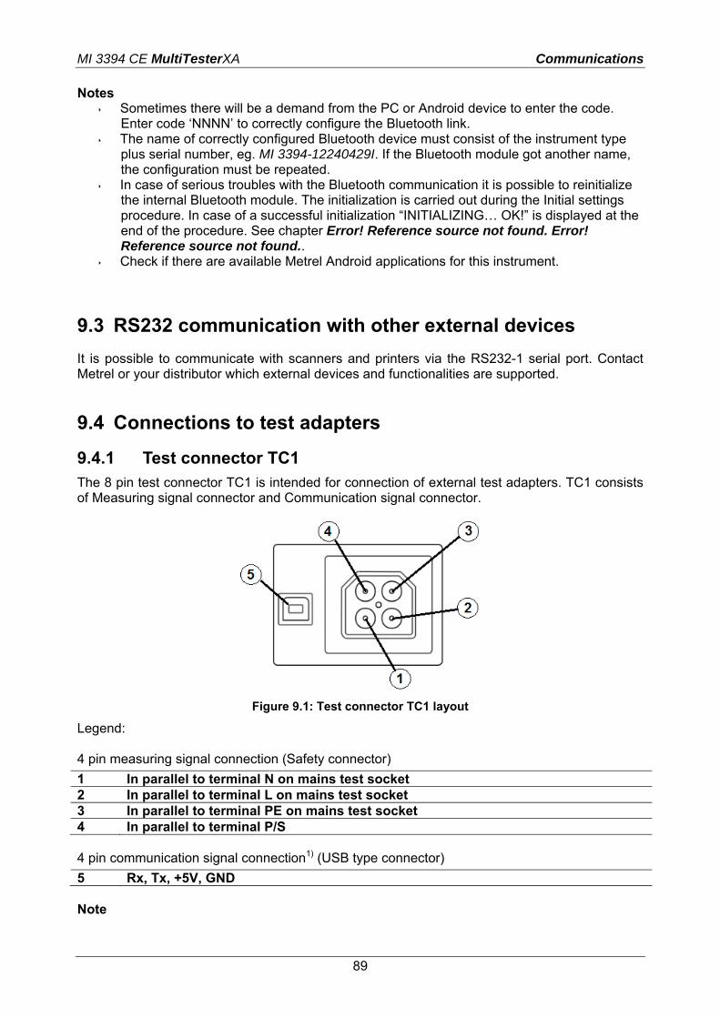
MI 3394 CE MultiTesterXA Communications
89
Notes Sometimes there will be a demand from the PC or Android device to enter the code.
Enter code ‘NNNN’ to correctly configure the Bluetooth link. The name of correctly configured Bluetooth device must consist of the instrument type
plus serial number, eg. MI 3394-12240429I. If the Bluetooth module got another name, the configuration must be repeated.
In case of serious troubles with the Bluetooth communication it is possible to reinitialize the internal Bluetooth module. The initialization is carried out during the Initial settings procedure. In case of a successful initialization “INITIALIZING… OK!” is displayed at the end of the procedure. See chapter Error! Reference source not found. Error! Reference source not found..
Check if there are available Metrel Android applications for this instrument.
9.3 RS232 communication with other external devices
It is possible to communicate with scanners and printers via the RS232-1 serial port. Contact Metrel or your distributor which external devices and functionalities are supported.
9.4 Connections to test adapters
9.4.1 Test connector TC1 The 8 pin test connector TC1 is intended for connection of external test adapters. TC1 consists of Measuring signal connector and Communication signal connector.
Figure 9.1: Test connector TC1 layout
Legend: 4 pin measuring signal connection (Safety connector)
1 In parallel to terminal N on mains test socket 2 In parallel to terminal L on mains test socket 3 In parallel to terminal PE on mains test socket 4 In parallel to terminal P/S 4 pin communication signal connection1) (USB type connector)
5 Rx, Tx, +5V, GND Note

MI 3394 CE MultiTesterXA Communications
90
1)Do not connect USB communication cable to 4 pin communication signal connector. It is intended only for connection to test adapters.
9.5 INPUTs
The DB9 connector INPUTs is intended for connection of external control signals.
Figure 9.2: INPUT connector - pin layout
Legend:
Pin Description Type 1 IN_1 External input 1
Input low: < 1 V d.c. against earth Input high: > 4.5 V d.c. against earth Umax: 24 V a.c, d.c against earth
2 IN_2 External input 2 3 IN_3 External input 3 4 IN_4 External input 4 5 IN_5 External input 5
9.6 OUTPUTs
Via the DB9 connector OUTPUT four control signals for external devices are provided.
Figure 9.3: OUTPUT connector - pin layout
Legend:
Pin Description Type 1 OUT_1 Control output 1 NO relay,
Umax: 24V, Imax: 1.5 A Output low: open contact Output high: closed contact
2 OUT_2 Control output 2 3 OUT_3 Control output 3 4 OUT_4 Control output 4

MI 3394 CE MultiTesterXA Technical specifications
91
10 Technical specifications
10.1 HV AC, HV AC programmable
Voltage a.c. Range Resolution Accuracy U 0 V ... 1999 V 1 V (3 % of reading) 2.00 kV ... 5.99 kV 10 V (3 % of reading) Current a.c. (apparent) Range Resolution Accuracy I 0.0 mA ... 99.9 mA 0.1 mA (3 % of reading + 3 D) Current a.c.(capacitive, resistive) Range Resolution Accuracy Ir 0.0 mA ... 99.9 mA 0.1 mA Indicative Ic -99.9 mA ... 99.9 mA 0.1 mA Indicative Output voltage ................................................. 100 V … 1000 V (-0/+10%), ......................................................................... 1010 V … 5000 V (-0/+5%) floating to earth Trip out time (if apparent current exceeds high limit) .......... < 30 ms Test terminals Function Connections Withstanding voltage (HVAC, HVAC-P) HV(~,+) ↔ HV(~,-)
10.2 HV DC, HV DC programmable
Voltage d.c. Range Resolution Accuracy U 0 V ... 1999 V 1 V (3 % of reading) 2.00 kV ... 6.99 kV 10 V (3 % of reading) Current d.c. Range Resolution Accuracy I 0.01 mA ... 9.99 mA 0.01 mA (5 % of reading + 3 D) Output voltage ................................................. 100 V … 1000 V (-0/+10%), ......................................................................... 1050 V … 6000 V (-0/+5%) floating to earth Ripple voltage .................................................. 3 % Trip out time (if current exceeds high limit) ...... < 30 ms Max. capacitive load ........................................ 2 µF
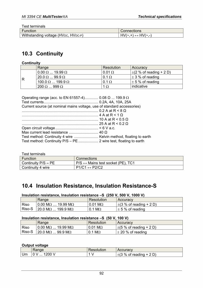
MI 3394 CE MultiTesterXA Technical specifications
92
Test terminals Function Connections Withstanding voltage (HVDC, HVDC-P) HV(~,+) ↔ HV(~,-)
10.3 Continuity
Continuity Range Resolution Accuracy
R
0.00 ... 19.99 0.01 (2 % of reading + 2 D) 20.0 ... 99.9 0.1 3 % of reading 100.0 ... 199.9 0.1 5 % of reading 200 ... 999 1 indicative
Operating range (acc. to EN 61557-4) ............. 0.08 Ω ... 199.9 Test currents .................................................... 0.2A, 4A, 10A, 25A Current source (at nominal mains voltage, use of standard accessories) ......................................................................... 0.2 A at R < 8 Ω ......................................................................... 4 A at R < 1 Ω ......................................................................... 10 A at R < 0.5 Ω ......................................................................... 25 A at R < 0.2 Ω Open circuit voltage ......................................... < 6 V a.c. Max current lead resistance ............................ 40 Ω Test method: Continuity 4 wire ....................... Kelvin method, floating to earth Test method: Continuity P/S – PE ................... 2 wire test, floating to earth Test terminals Function Connections Continuity P/S – PE P/S ↔ Mains test socket (PE), TC1 Continuity 4 wire P1/C1 ↔ P2/C2
10.4 Insulation Resistance, Insulation Resistance-S
Insulation resistance, Insulation resistance –S (250 V, 500 V, 1000 V) Range Resolution Accuracy Riso Riso-S
0.00 M … 19.99 M 0.01 M (3 % of reading + 2 D) 20.0 M ... 199.9 M 0.1 M 5 % of reading
Insulation resistance, Insulation resistance –S (50 V, 100 V) Range Resolution Accuracy Riso Riso-S
0.00 M ... 19.99 M 0.01 M (5 % of reading + 2 D) 20.0 M ... 99.9 M 0.1 M 20 % of reading
Output voltage Range Resolution Accuracy Um 0 V ... 1200 V 1 V (3 % of reading + 2 D)

MI 3394 CE MultiTesterXA Technical specifications
93
Operating range (acc. to EN 61557-2) ......... 0.08 M ... 199.9 M Nominal voltages Un (d.c.) .......................... 50 V, 100 V, 250 V, 500 V, 1000V (- 0 %, + 10 %) Short circuit current ..................................... max. 2.0 mA Test terminals Function Connections Insulation Mains test socket (LN), ISO(+) ↔ Mains test socket (PE), ISO(-),
TC1 Insulation – S Mains test socket (LN), ISO(+) ↔ P/S, TC1
10.5 Substitute Leakage Current, Substitute Leakage Current - S
Substitute leakage current, Substitute leakage current - S Range Resolution Accuracy Isub Isub-S
0.00 mA ... 19.99 mA 10 µA (5 % of reading + 3 D)
Operating range (acc. to EN 61557-16) ........... 0.12 mA ... 19.99 mA Open circuit voltage ......................................... < 50 V a.c. Current calculated to mains supply voltage (110 V or 230 V) is displayed. Test terminals: Function Connections Subleakage Mains test socket (LN), SUB1 ↔ Mains test socket (PE), SUB2,
TC1 Subleakage – S Mains test socket (LN), SUB1 ↔ P/S, TC1
10.6 Differential Leakage current
Differential leakage current Range Resolution Accuracy Idiff 0.00 mA ... 19.99 mA 0.01 mA (3 % of reading + 5 D) Power (active) Range Resolution Accuracy
P 0 W ... 999 W 1 W (5 % of reading + 5 D) 1.00 kW ... 3.70 kW 10 W 5 % of reading
Operating range (acc. to EN 61557-16) ........... 0.19 mA ... 19.99 mA Frequency response of measuring circuit ........ complies with EN 61010 - Figure A1 Influence of load current .................................. < 0.02 mA/A Test terminals: Function Connections Differential leakage Mains test socket (LN), TC1

MI 3394 CE MultiTesterXA Technical specifications
94
10.7 PE leakage current
PE leakage current Range Resolution Accuracy Ipe 0.00 mA ... 19.99 mA 0.01 mA (3 % of reading + 3 D) Power (active) Range Resolution Accuracy
P 0 W ... 999 W 1 W (5 % of reading + 5 D) 1.00 kW ... 3.70 kW 10 W 5 % of reading
Operating range (acc. to EN 61557-16) ........... 0.12 mA ... 19.99 mA Frequency response of measuring circuit ........ complies with EN 61010 - Figure A1 Test terminals: Function Connections PE leakage Mains test socket, TC1
10.8 Touch leakage current
Touch leakage current Range Resolution Accuracy Itou 0.00 mA ... 19.99 mA 0.01 mA (3 % of reading + 3 D) Power (active) Range Resolution Accuracy
P 0 W ... 999 W 1 W (5 % of reading + 5 D) 1.00 kW ... 3.70 kW 10 W 5 % of reading
Operating range (acc. to EN 61557-16) ........... 0.12 mA ... 19.99 mA Frequency response of measuring circuit ........ complies with EN 61010 - Figure A1 Output: Function Connections Touch leakage Mains test socket ↔ P/S, TC1

MI 3394 CE MultiTesterXA Technical specifications
95
10.9 Power
Power (active) Range Resolution Accuracy
P 0 W ... 999 W 1 W (5 % of reading + 5 D) 1.00 kW ... 3.70 kW 10 W 5 % of reading
Power (apparent) Range Resolution Accuracy
S 0 VA ... 999 VA 1 VA (5 % of reading + 5 D) 1.00 kVA ... 3.70 kVA 10 VA 5 % of reading
Power (reactive) Range Resolution Accuracy
Q (0 VAr ... 999) VAr 1 VAr (5 % of reading + 5 D) (1.00 kVAr ... 3.70) kVAr 10 VAr 5 % of reading
Power factor
Range Resolution Accuracy
PF 0.00i ... 1.00i
0.00c ... 1.00c 0.01 (5 % of reading + 5 D)
Total Harmonic Distortion (voltage)
Range Resolution Accuracy THDU 0.0 % ... 99.9 % 0.1 % (5 % of reading + 5 D) Total Harmonic Distortion (current)
Range Resolution Accuracy THDI 0.0 % ... 99.9 % 0.1 % (5 % of reading + 5 D) Cosinus Φ
Range Resolution Accuracy
Cos Phi 0.00i ... 1.00i
0.00c ... 1.00c 0.01 (5 % of reading + 5 D)
Voltage
Range Resolution Accuracy
U 0.0 V ... 199.9 V 0.1 V (3 % of reading + 10 D) 200 V ... 264 V 1 V 3 % of reading
Current
Range Resolution Accuracy I 0.00 A ... 16.00 A 0.01 A (3 % of reading + 5 D) Test terminals: Function Connections Power Mains test socket, TC1

MI 3394 CE MultiTesterXA Technical specifications
96
10.10 Leak’s & Power
Power (active) Range Resolution Accuracy
P 0 W ... 999 W 1 W (5 % of reading + 5 D) 1.00 kW ... 3.70 kW 10 W 5 % of reading
Power (apparent) Range Resolution Accuracy
S 0 VA ... 999 VA 1 VA (5 % of reading + 5 D) 1.00 kVA ... 3.70 kVA 10 VA 5 % of reading
Power (reactive) Range Resolution Accuracy
Q 0 VAr ... 999 VAr 1 VAr (5 % of reading + 5 D) 1.00 kVAr ... 3.70 kVAr 10 VAr 5 % of reading
Power factor
Range Resolution Accuracy
PF 0.00i ... 1.00i
0.00c ... 1.00c 0.01 (5 % of reading + 5 D)
Total Harmonic Distortion (voltage)
Range Resolution Accuracy THDU 0.0 % ... 99.9 % 0.1 % (5 % of reading + 5 D) Total Harmonic Distortion (current)
Range Resolution Accuracy THDI 0.0 % ... 99.9 % 0.1 % (5 % of reading + 5 D) Cosinus Φ
Range Resolution Accuracy Cos Phi 0.00i ... 1.00i
0.00c ... 1.00c 0.01 (5 % of reading + 5 D)
Voltage
Range Resolution Accuracy
U 0.0 V ... 199.9 V 0.1 V (3 % of reading + 10 D) 200 V ... 264 V 1 V 3 % of reading
Current
Range Resolution Accuracy I 0.00 A ... 16.00 A 0.01 A (3 % of reading + 5 D) Differential leakage current Range Resolution Accuracy Idiff 0.00 mA ... 19.99 mA 0.01 mA (3 % of reading + 5 D)

MI 3394 CE MultiTesterXA Technical specifications
97
Operating range (acc. to EN 61557-16) ........... 0.19 mA ... 19.99 mA Frequency response of measuring circuit ........ complies with EN 61010 - Figure A1 Influence of load current .................................. < 0.02 mA/A Touch leakage current Range Resolution Accuracy Itou 0.00 mA ... 19.99 mA 0.01 mA (3 % of reading + 3 D) Operating range (acc. to EN 61557-16) ........... 0.12 mA ... 19.99 mA Frequency response of measuring circuit ........ complies with EN 61010 - Figure A1 Test terminals: Function Connections Power Mains test socket, TC1 Differential leakage Mains test socket (LN), TC1 Touch leakage Mains test socket ↔ P/S, TC1
10.11 Discharging time
Discharging time Range Resolution Accuracy t 0.0 s ... 9.9 s 0.1 s (5 % of reading + 2 D)
Peak voltage Range Resolution Accuracy Up 0 V ... 550 V 1 V (5 % of reading + 3 D)
Operating range (acc. to EN 61557-14) ........... 0.8 s ... 9.9 s High limits ........................................................ 1 s, 5 s Threshold voltage ............................................ 60 V, 120 V Input resistance ............................................... 48 M Max. load current (Output = Socket)….. .......... 10 A Automatic disconnection at ULNpeak if DUT (Device Under Test) is connected to mains test socket.
Test terminals Function Connections Discharging time External DISCH1 ↔ DISCH2 Discharging time Socket Mains test socket (L,N), TC1

MI 3394 CE MultiTesterXA Technical specifications
98
10.12 General data
Power supply Supply voltage, frequency ............................... 110 V / 230 V AC, 50 Hz / 60 Hz Supply voltage tolerance ................................. 10 % Max. power consumption ................................. 600 W (without load on mains test socket) Max. power consumption ................................. 4.5 kW (with load on mains test socket) Mains supply overvoltage category ................. CAT II / 300V Altitude ............................................................. ≤ 2000 m
Measuring categories DISCH1 / DISCH2 ........................................... CAT II / 600 V ISO(+) SUB1 / ISO(-) SUB2 ............................ CAT II / 300 V P1, C1 / P2, C2 ................................................ CAT II / 300 V P/S ................................................................... CAT II / 300 V TC1 .................................................................. CAT II / 300 V Mains test socket ............................................. CAT II / 300 V Altitude ............................................................. ≤ 2000 m Protection classifications Power supply ................................................... Class I HV output ......................................................... 5 kV a.c. / 6 kV d.c., double insulation Pollution degree ............................................... 2 Degree of protection ........................................ IP 50 (closed case) ……………………………………. ..................... IP 40 (open case) ......................................................................... IP 20 (mains test socket) Case ................................................................ Shock proof plastic / portable INPUTs ............................................................ 24 Vmax, earthed OUTPUTs ........................................................ 24 Vmax, earthed Display ............................................................. Colour TFT display, 4.3 inch, 480 x 272 pixels Touch screen ................................................... Capacitive Communication Memory ............................................................ depends on microSD card size RS232 interfaces ............................................. two DB9 ports USB 2.0 ........................................................... Standard USB Type B Bluetooth ......................................................... Class 2 I/Os Inputs ............................................................... DB9 connector (24 V max) Outputs ............................................................ DB9 connector (NO relais, 24 V max, 1.5 A max) Dimensions (w×h×d): ....................................... 43.5 cm × 29.2 cm × 15.5 cm Weight ............................................................. 8.4 kg Reference conditions Reference temperature range:......................... 15 C ... 35 C Reference humidity range: .............................. 35 % ... 65 % RH Operation conditions Working temperature range: ............................ 0 C ... +40 C Maximum relative humidity: ............................. 85 % RH (0 C ... 40 C), non-condensing

MI 3394 CE MultiTesterXA Technical specifications
99
Storage conditions Temperature range: ......................................... -10 C ... +60 C Maximum relative humidity: ............................. 90 % RH (-10 C ... +40 C) ......................................................................... 80 % RH (40 C ... 60 C) Accuracies apply for 1 year in reference conditions. Temperature coefficient outside these limits is 0.2 % of measured value per C plus 1 digit, otherwise noted. Fuses 2 x T 16 A / 250 V, 32 mm 6.3 mm / 1500 A (protection of mains test socket) 2 x T 5 A / 250 V, 20 mm 5 mm / 1500 A (instrument protection)

MI 3394 CE MultiTesterXA Appendix A
100
Appendix A - Structure objects in CE MultiTesterXA
Icon Default name Description
NODE Node
PROJECT Project
LOCATION Location
APPLIANCE Appliance (short description)
APPLIANCE FD Appliance (full description)
MI 3394 CE MultiTesterXA Appendix B
101
Appendix B - Profile Notes There are no specific profile notes for CE MultiTesterXA MI 3394.

MI 3394 CE MultiTesterXA Appendix C
102
Appendix C - Default list of Auto tests Pre-programmed Auto test sequences No. Name Description
1 DEMO_1 This Auto test is just for demonstration of manipulation of Auto test operation.
2 DEMO_2 This Auto test is just for demonstration of manipulation of Auto test operation.
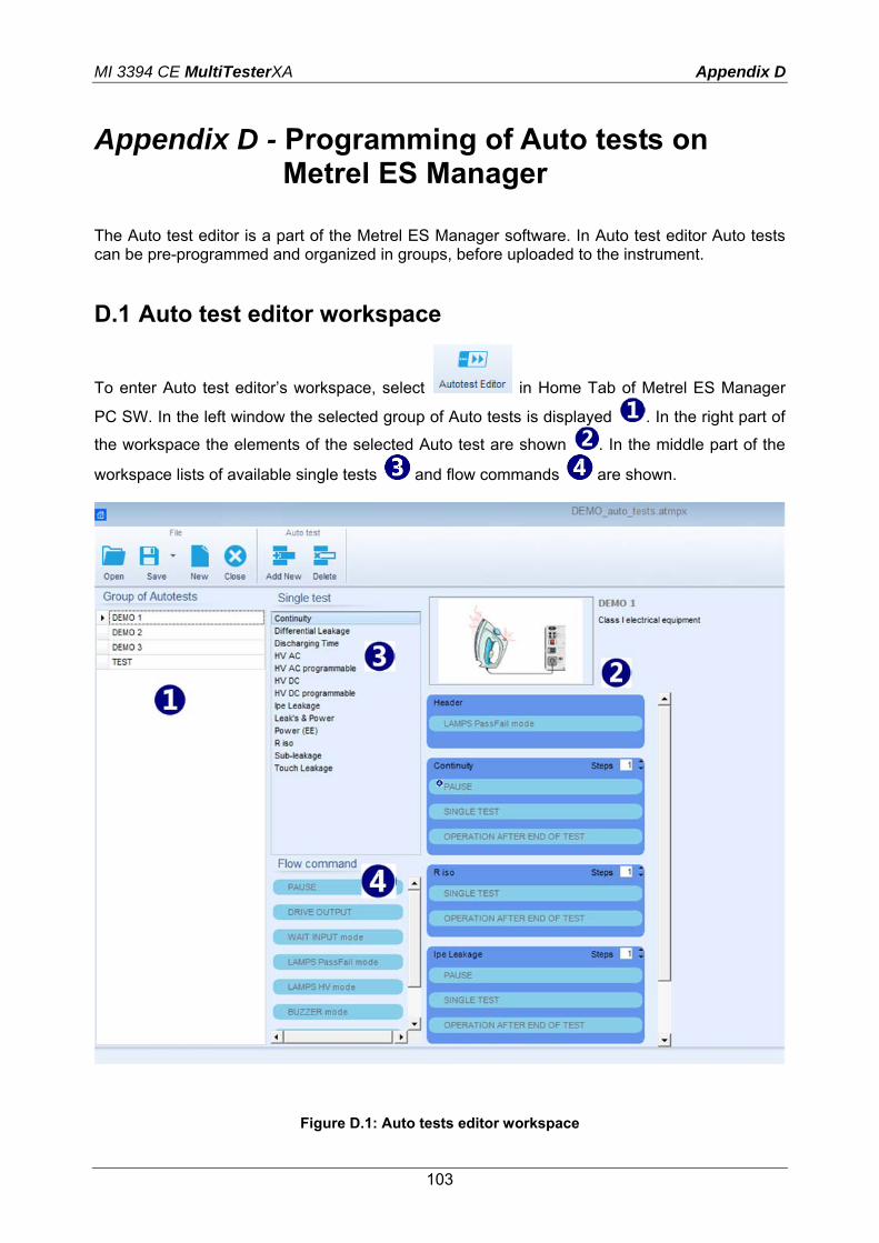
MI 3394 CE MultiTesterXA Appendix D
103
Appendix D - Programming of Auto tests on Metrel ES Manager
The Auto test editor is a part of the Metrel ES Manager software. In Auto test editor Auto tests can be pre-programmed and organized in groups, before uploaded to the instrument.
D.1 Auto test editor workspace
To enter Auto test editor’s workspace, select in Home Tab of Metrel ES Manager
PC SW. In the left window the selected group of Auto tests is displayed . In the right part of
the workspace the elements of the selected Auto test are shown . In the middle part of the
workspace lists of available single tests and flow commands are shown.
Figure D.1: Auto tests editor workspace

MI 3394 CE MultiTesterXA Appendix D
104
An Auto test consists of the First step (Header), one or more Measuring steps and ends with the Last step (Result). By inserting appropriate elements and setting their parameters, arbitrary Auto test sequences can be created.
Figure D.2: Example of an Auto test header
Figure D.3: Example of a measurement step
Figure D.4: Example of an Auto test result
D.2 Managing groups of Auto tests
The Auto tests can be divided into different user defined groups of Auto tests. Each group of Auto tests is stored in a file. The Auto tests in the selected group are displayed in the left side of the Auto test editor workspace.
Figure D.5: Auto tests in a group
Options on file (opened group of Auto tests):
Opens a file (group).
Saves / Saves as the opened group to file.
Creates a new file (group).

MI 3394 CE MultiTesterXA Appendix D
105
Closes the file (group).
Options (on individual Auto test in a group)
Adds a new Auto test to the group.
Deletes the selected Auto test.
Right click on the selected Auto test gives additional possibilities:
Makes a copy of the selected Auto tests.
, or double click on the Auto test name
Edits the Header of the selected Auto test (see Figure D.6 Editing the Auto test header).
Figure D.6: Editing the Auto test header
D.3 Elements of an Auto test
D.3.1 Auto test steps There are three kinds of Auto test steps. Header The Header step is empty by default. Flow commands can be added to the Header step.

MI 3394 CE MultiTesterXA Appendix D
106
Measurement step The Measurement step contains a Single test and the Operation after end of test flow command by default. Other Flow commands can also be added to the Measurement step. Result The result step is empty by default. Flow commands can be added to the Result step.
D.3.2 Single tests Single tests are the same as in Metrel ES Manager Measurement menu. Limits and parameters of the measurements can be set. Results and sub-results can’t be set.
D.3.3 Flow commands Flow commands are used to control the flow of measurements. Refer to chapter D.5 Description of flow commands for more information.
D.3.4 Number of measurement steps Often the same measurement step has to be performed on multiple points on the device under test. It is possible to set how many times a Measurement step will be repeated. All carried out individual Single test results are stored in the Auto test result as if they were programmed as independent measuring steps.
D.4 Creating / modifying an Auto test
If creating a new Auto test from scratch, the First step (Header) and the Last step (Result) are offered by default. Options
Adding a measurement step By double clicking on a Single test a new measurement step will appear as the last of measurement steps. It can also be dragged and dropped on the appropriate position in the Auto test.
Adding flow commands Selected flow command can be dragged from the list of Flow commands and dropped on the appropriate place in any Auto test step.
Changing position of flow command inside one step
By a click on an element and use of , keys.
Viewing / changing parameters of flow commands or single tests.
By a double click on the element.
Setting number of measurement steps
By setting a number from 1 to 20 in the field.
Right click on the selected measurement step / flow command
Copy – Paste before
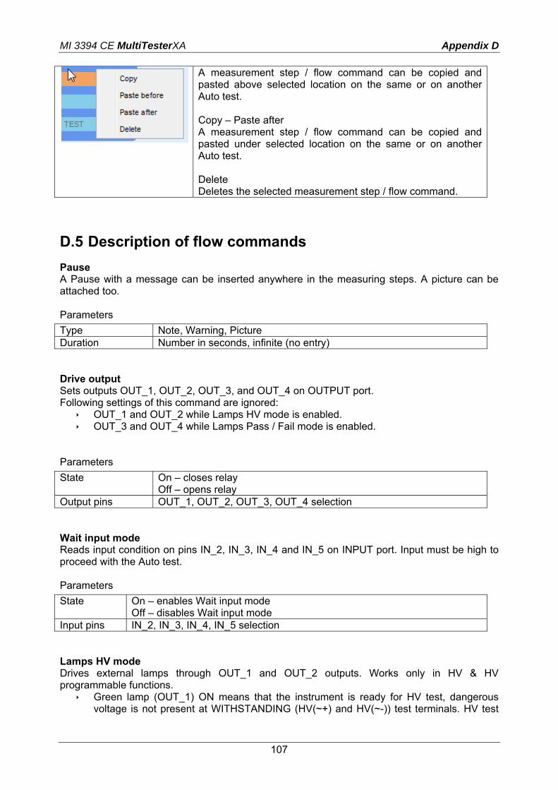
MI 3394 CE MultiTesterXA Appendix D
107
A measurement step / flow command can be copied and pasted above selected location on the same or on another Auto test. Copy – Paste after A measurement step / flow command can be copied and pasted under selected location on the same or on another Auto test. Delete Deletes the selected measurement step / flow command.
D.5 Description of flow commands
Pause A Pause with a message can be inserted anywhere in the measuring steps. A picture can be attached too. Parameters
Type Note, Warning, Picture Duration Number in seconds, infinite (no entry) Drive output Sets outputs OUT_1, OUT_2, OUT_3, and OUT_4 on OUTPUT port. Following settings of this command are ignored:
OUT_1 and OUT_2 while Lamps HV mode is enabled. OUT_3 and OUT_4 while Lamps Pass / Fail mode is enabled.
Parameters
State On – closes relay Off – opens relay
Output pins OUT_1, OUT_2, OUT_3, OUT_4 selection Wait input mode Reads input condition on pins IN_2, IN_3, IN_4 and IN_5 on INPUT port. Input must be high to proceed with the Auto test. Parameters
State On – enables Wait input mode Off – disables Wait input mode
Input pins IN_2, IN_3, IN_4, IN_5 selection Lamps HV mode Drives external lamps through OUT_1 and OUT_2 outputs. Works only in HV & HV programmable functions.
Green lamp (OUT_1) ON means that the instrument is ready for HV test, dangerous voltage is not present at WITHSTANDING (HV(~+) and HV(~-)) test terminals. HV test
MI 3394 CE MultiTesterXA Appendix D
108
can be started with HV TEST key. Green lamp turns on before first flow command in step that contains HV test. Green lamp turns off as soon as red lamp turns on (blinking or not).
Red lamp (OUT_2) blinking means that high voltage will be applied to WITHSTANDING (HV(~+) and HV(~-)) test terminals as soon as all input conditions will be fulfilled.
Red lamp (OUT_2) ON means that dangerous voltage is present at WITHSTANDING (HV(~+) and HV(~-)) test terminals. Red lamp turns on before measurement. Red lamp turns off after measurement.
While Lamps HV mode command is enabled the settings of Drive output command for OUT_1 and OUT_2 is ignored. Parameters State On – enables Lamps HV mode
Off – disables Lamps HV mode Lamps Pass / Fail mode Drives external lamps through OUT_3 and OUT_4 outputs. During measurement the lights reflect status icon in single test. After measurement
Green lamp (OUT_3) lights ON when test has passed. Lamp is lit until next step is started.
Red lamp (OUT_4) lights ON when test has failed. Lamp is lit until next step is started. Lights turn off at the beginning of next step.
While Lamps Pass / Fail mode command is enabled the settings of Drive output command for OUT_3 and OUT_4 is ignored. Parameters
State On – enables Lamps Pass / Fail mode Off – disables Lamps Pass / Fail mode
Buzzer mode Passed or failed measurement is indicated with beeps.
Pass – double beep after the test Fail – long beep after the test
Beep happens right after single test measurement. Parameters
State On – enables Buzzer mode Off – disables Buzzer mode
External TEST / OK key mode Instrument enables external TEST / OK key (ENTER / TEST / HV TEST). Functionality of the IN_1 pin is the same as of the TEST / OK / HV TEST key. Parameters
State On – enables External TEST / OK key mode Off – disables External TEST / OK key mode
No notifications mode
MI 3394 CE MultiTesterXA Appendix D
109
Instrument skips pre-test warnings (see CE MultiTesterXA User Manual, chapter 4.4 Symbols and messages for more information). Parameters
State On – enables No notifications mode Off – disables No notifications mode