CE MODEL -1 ANS KEY
16
PART-A (2-MARK QUESTIONS) 1. Define Transducer? It is device used to convert one form of energy into another form of energy. For example solar panel, it is converting the solar energy into Power. 2. What is voice coil? It is defined as, coil of wire attached to the apex of a loudspeaker cone. It provides the motive force to the cone by the reaction of a magnetic field to the current passing through it. It is referred as voice coil. 3. What is composite video signal? Composite video (1 channel) is an analog video transmission (no audio) that carries standard definition video typically at 480i or 576i resolution. Hence this type of video signal is called as composite video signal 4. Define CRT? It stands for cathode ray tube. It contains two ends (i.e) Narrow tube that contains electron gun at one end and a phosphorous coated region at another end. It is used to produce the video signal. 5. What is ERCO? It is noting but Error detection and error correction, used in CD system. 6. What are the various layers present in the disc? There are 3 different layers will present in the disc. They are (i) transparent layer, (ii) Protection layer, (iii) Reflection layer. 7. Define switching system? It is a system used to enable any type of terminal, in order to pass the information from one place to another place. The different types of switching system are circuit switching, packet switching and message switching etc. 8. What is WLL? Wireless local loop (WLL), is a term for the use of a wireless communications link as the "last mile / first mile" connection for delivering plain old telephone service (POTS) or Internet access (marketed under the term "broadband") to telecommunications customers. Various types of WLL systems and technologies exist. 9. Define Magnetron? The microwave radiation of microwave ovens and some radar applications is produced by a device called a magnetron. The magnetron is called a "crossed-field" device in the industry because both magnetic and electric fields are employed in its operation, and they are produced in perpendicular directions so that they cross. 10. What is refrigerator? A refrigerator or fridge is a common household appliance that consists of a thermally insulated compartment and a heat pump that transfers heat from the inside of the fridge to its external environment so that the inside of the fridge is cooled to a temperature below the ambient temperature of the room.
-
Upload
thiagu-rajiv -
Category
Documents
-
view
237 -
download
4
Transcript of CE MODEL -1 ANS KEY
PART-A (2-MARK QUESTIONS)
1. Define Transducer?
It is device used to convert one form of energy into another form of energy. For example solar
panel, it is converting the solar energy into Power.
2. What is voice coil?
It is defined as, coil of wire attached to the apex of a loudspeaker cone. It provides the motive
force to the cone by the reaction of a magnetic field to the current passing through it. It is referred
as voice coil.
3. What is composite video signal?
Composite video (1 channel) is an analog video transmission (no audio) that carries
standard definition video typically at 480i or 576i resolution. Hence this type of video signal is
called as composite video signal
4. Define CRT?
It stands for cathode ray tube. It contains two ends (i.e) Narrow tube that contains electron gun at
one end and a phosphorous coated region at another end. It is used to produce the video signal.
5. What is ERCO?
It is noting but Error detection and error correction, used in CD system.
6. What are the various layers present in the disc?
There are 3 different layers will present in the disc. They are (i) transparent layer, (ii)
Protection layer, (iii) Reflection layer.
7. Define switching system?
It is a system used to enable any type of terminal, in order to pass the information from one place
to another place. The different types of switching system are circuit switching, packet switching
and message switching etc.
8. What is WLL?
Wireless local loop (WLL), is a term for the use of a wireless communications link as the
"last mile / first mile" connection for delivering plain old telephone service (POTS) or Internet
access (marketed under the term "broadband") to telecommunications customers. Various types
of WLL systems and technologies exist.
9. Define Magnetron?
The microwave radiation of microwave ovens and some radar applications is produced by
a device called a magnetron. The magnetron is called a "crossed-field" device in the industry
because both magnetic and electric fields are employed in its operation, and they are produced in
perpendicular directions so that they cross.
10. What is refrigerator?
A refrigerator or fridge is a common household appliance that consists of a thermally
insulated compartment and a heat pump that transfers heat from the inside of the fridge to its
external environment so that the inside of the fridge is cooled to a temperature below the ambient
temperature of the room.
PART-B (11 MARKS)
11. Discuss the principle of operation of electrostatic loudspeaker along with its diagram?
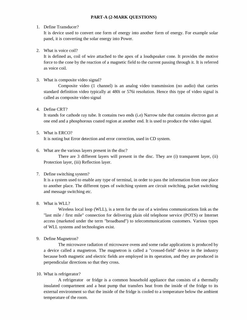
An electrostatic loudspeaker (ESL) is a loudspeaker design in which sound is generated
by the force exerted on a membrane suspended in an electrostatic field.
The speakers use a thin flat diaphragm usually consisting of a plastic sheet coated with a
conductive material such as graphite sandwiched between two electrically conductive grids, with a small air gap between the diaphragm and grids. For low distortion operation, the diaphragm must operate with a
constant charge on its surface, rather than with a constant voltage (charge and voltage is not the same
thing). This is accomplished by either or both of two techniques: the diaphragm's conductive coating is
chosen and applied in a manner to give it a very high surface resistivity, and/or a large value resistor is placed in series between the EHT (Extra High Tension or Voltage) power supply and the diaphragm
(resistor not shown in the diagram here). However, the latter technique will still allow distortion as the
charge will migrate across the diaphragm to the point closest to the "grid" or electrode thereby increasing the force moving the diaphragm, this will occur at audio frequency so the diaphragm requires a high
resistance (Meg ohms) to slow the movement of charge for a practical speaker.
The diaphragm is usually made from a polyester film (thickness 2–20 µm) with exceptional
mechanical properties, such as PET film. By means of the conductive coating and an external high voltage supply the diaphragm is held at a DC potential of several kilovolts with respect to the grids. The
grids are driven by the audio signal; front and rear grid is driven in ant phase. As a result a uniform
electrostatic field proportional to the audio signal is produced between both grids. This causes a force to
be exerted on the charged diaphragm, and its resulting movement drives the air on either side of it.
In virtually all electrostatic loudspeakers the diaphragm is driven by two grids, one on either side, because the force exerted on the diaphragm by a single grid will be unacceptably non-linear, thus causing
harmonic distortion. Using grids on both sides cancels out voltage dependent part of non-linearity but
leaves charge (attractive force) dependent part.[1]
The result is near complete absence of harmonic distortion. In one recent design, the diaphragm is driven with the audio signal, with the static charge
located on the grids (Transparent Sound Solutions).The grids must be able to generate as uniform an
electric field as possible, while still allowing for sound to pass through. Suitable grid constructions are
therefore perforated metal sheets, a frame with tensioned wire, wire rods, etc.
To generate sufficient field strength, the audio signal on the grids must be of high voltage. The electrostatic construction is in effect a capacitor, and current is only needed to charge the capacitance
created by the diaphragm and the stator plates (previous paragraphs referred to as grids or electrodes).
This type of speaker is therefore a high-impedance device. In contrast, a modern electrodynamics cone

loudspeaker is a low impedance device, with higher current requirements. As a result, impedance
matching is necessary in order to use a normal amplifier. Most often a transformer is used to this end. Construction of this transformer is critical as it must provide a constant (often high) transformation ratio
over the entire audible frequency range (i.e. large bandwidth) and so avoid distortion. The transformer is
almost always specific to a particular electrostatic speaker. To date, Acoustic built the only commercial
"transformer-less" electrostatic loudspeaker. In this design, the audio signal is applied directly to the stators from a built-in high-voltage valve amplifier (as valves are also high impedance devices), without
use of a step-up transformer.
12. Explain the concept of carbon Microphones?
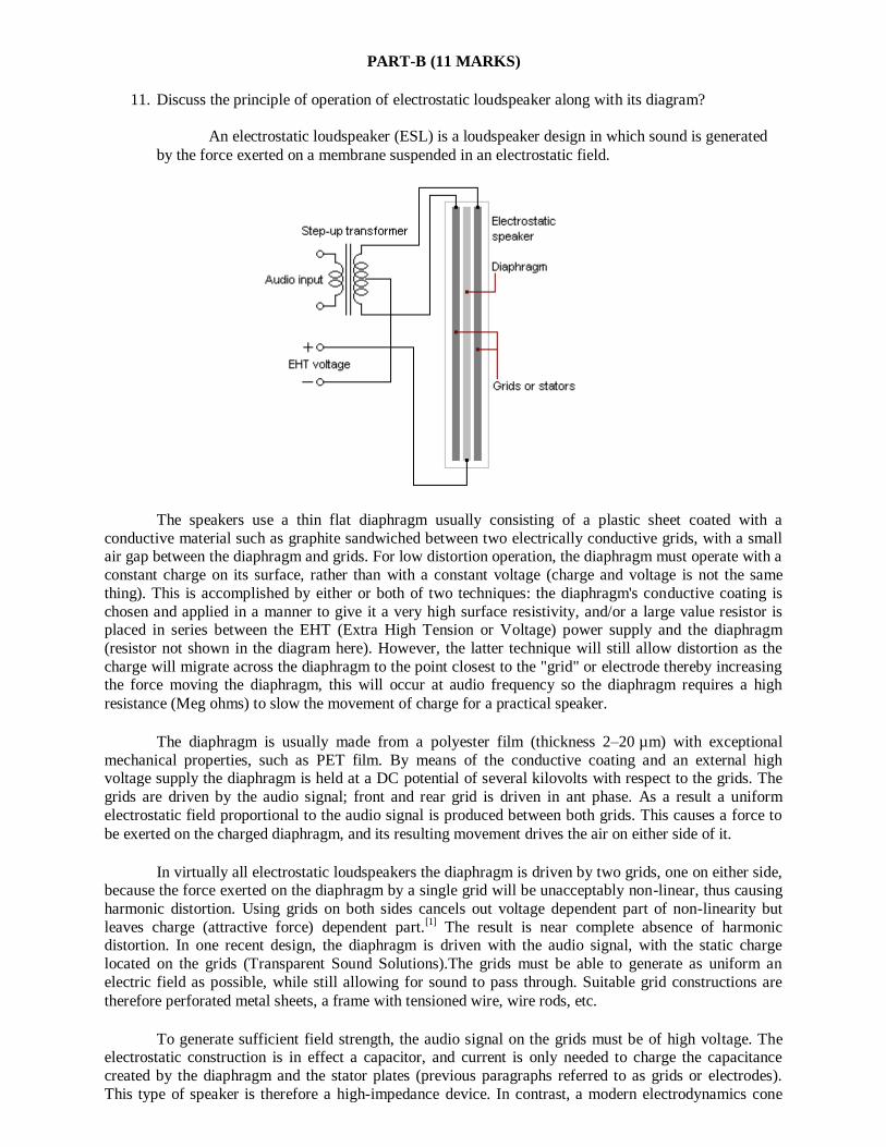
A carbon microphone, also known as a carbon button microphone (or sometimes just a button
microphone), use a capsule or button containing carbon granules pressed between two metal plates like the Berliner and Edison microphones. A voltage is applied across the metal plates, causing a small current
to flow through the carbon. One of the plates, the diaphragm, vibrates in sympathy with incident sound
waves, applying a varying pressure to the carbon. The changing pressure deforms the granules, causing the contact area between each pair of adjacent granules to change, and this causes the electrical resistance
of the mass of granules to change. The changes in resistance cause a corresponding change in the current
flowing through the microphone, producing the electrical signal. Carbon microphones were once
commonly used in telephone
Unlike other microphone types, the carbon microphone can also be used as a type of amplifier, using a
small amount of sound energy to control a larger amount of electrical energy. Carbon microphones found
use as early telephone repeaters, making long distance phone calls possible in the era before vacuum tubes. These repeaters worked by mechanically coupling a magnetic telephone receiver to a carbon
microphone: the faint signal from the receiver was transferred to the microphone, with a resulting stronger
electrical signal to send down the line.
Moving-coil microphones use the same dynamic principle as in a loudspeaker, only reversed. A small movable induction coil, positioned in the magnetic field of a permanent magnet, is attached to the
diaphragm. When sound enters through the windscreen of the microphone, the sound wave moves the
diaphragm. When the diaphragm vibrates, the coil moves in the magnetic field, producing a varying current in the coil through electromagnetic induction. A single dynamic membrane does not respond
linearly to all audio frequencies. Some microphones for this reason utilize multiple membranes for the
different parts of the audio spectrum and then combine the resulting signals. Combining the multiple
signals correctly is difficult and designs that do this are rare and tend to be expensive. There are on the other hand several designs that are more specifically aimed towards isolated parts of the audio spectrum.
The AKG D 112, for example, is designed for bass response rather than treble.[16]
In audio engineering
several kinds of microphones are often used at the same time to get the best result.
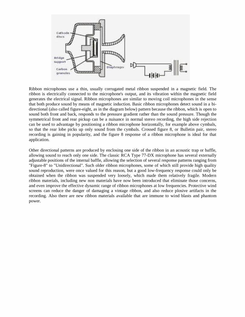
Ribbon microphones use a thin, usually corrugated metal ribbon suspended in a magnetic field. The ribbon is electrically connected to the microphone's output, and its vibration within the magnetic field
generates the electrical signal. Ribbon microphones are similar to moving coil microphones in the sense
that both produce sound by means of magnetic induction. Basic ribbon microphones detect sound in a bi-
directional (also called figure-eight, as in the diagram below) pattern because the ribbon, which is open to sound both front and back, responds to the pressure gradient rather than the sound pressure. Though the
symmetrical front and rear pickup can be a nuisance in normal stereo recording, the high side rejection
can be used to advantage by positioning a ribbon microphone horizontally, for example above cymbals, so that the rear lobe picks up only sound from the cymbals. Crossed figure 8, or Bulletin pair, stereo
recording is gaining in popularity, and the figure 8 response of a ribbon microphone is ideal for that
application.
Other directional patterns are produced by enclosing one side of the ribbon in an acoustic trap or baffle,
allowing sound to reach only one side. The classic RCA Type 77-DX microphone has several externally adjustable positions of the internal baffle, allowing the selection of several response patterns ranging from
"Figure-8" to "Unidirectional". Such older ribbon microphones, some of which still provide high quality
sound reproduction, were once valued for this reason, but a good low-frequency response could only be obtained when the ribbon was suspended very loosely, which made them relatively fragile. Modern
ribbon materials, including new non materials have now been introduced that eliminate those concerns,
and even improve the effective dynamic range of ribbon microphones at low frequencies. Protective wind screens can reduce the danger of damaging a vintage ribbon, and also reduce plosive artifacts in the
recording. Also there are new ribbon materials available that are immune to wind blasts and phantom
power.
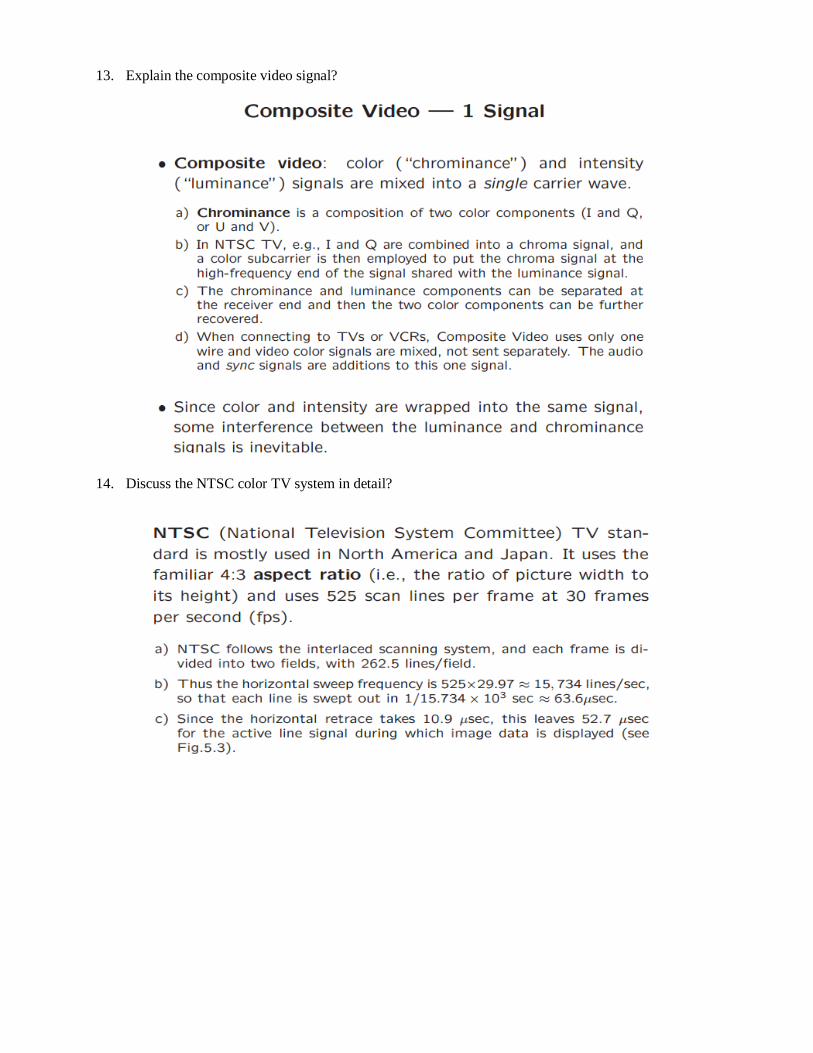
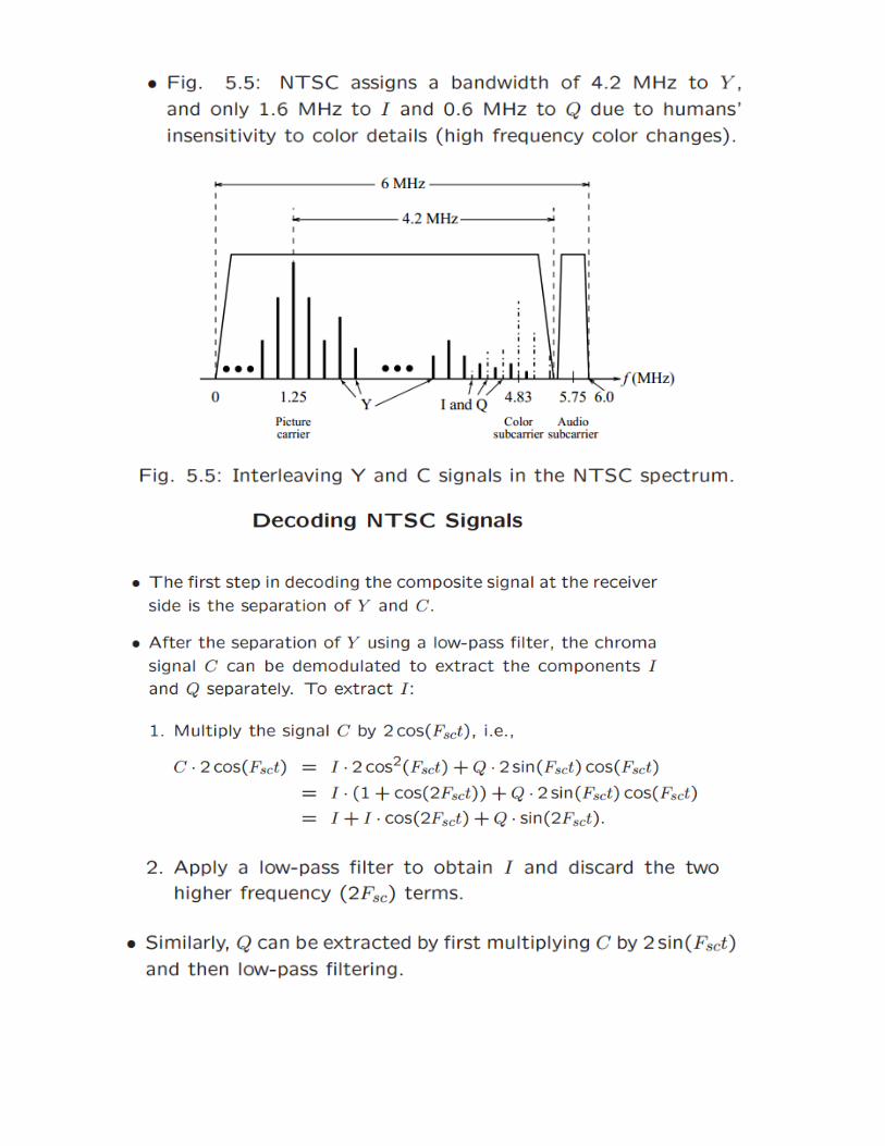
13. Explain the composite video signal?
14. Discuss the NTSC color TV system in detail?


15. Write briefly about the Processing of an audio signal?

17. Write briefly about the PAPX Switching?
A private branch exchange (PBX) is a telephone exchange that serves a particular business or office,
as opposed to one that a common carrier or telephone company operates for many businesses or for the
general public. PBXs are also referred to as:
PABX – private automatic branch exchange
EPABX – electronic private automatic branch exchange
PBXs make connections among the internal telephones of a private organization—usually a business—
and also connect them to the public switched telephone network (PSTN) via trunk lines. Because they incorporate telephones, fax machines, modems, and more, the general term "extension" is used to refer to
any end point on the branch.
PBXs are differentiated from "key systems" in that users of key systems manually select their own
outgoing lines, while PBXs select the outgoing line automatically. Hybrid systems combine features of
both.

Initially, the primary advantage of PBXs was cost savings on internal phone calls: handling the circuit
switching locally reduced charges for local phone service. As PBXs gained popularity, they started offering services that were not available in the operator network, such as hunt groups, call forwarding,
and extension dialing. In the 1960s a simulated PBX known as Centrex provided similar features from the
central telephone exchange.
Two significant developments during the 1990s led to new types of PBX systems. One was the massive
growth of data networks and increased public understanding of packet switching. Companies needed packet switched networks for data, so using them for telephone calls was tempting, and the availability of
the Internet as a global delivery system made packet switched communications even more attractive.
These factors led to the development of the VoIP PBX. (Technically, nothing was being "exchanged" any
more, but the abbreviation PBX was so widely understood that it remained in use.)
The other trend was the idea of focusing on core competence. PBX services had always been hard
to arrange for smaller companies, and many companies realized that handling their own telephony was
not their core competence. These considerations gave rise to the concept of hosted PBX. In a hosted
setup, the PBX is located at and managed by the telephone service provider, and features and calls are delivered via the Internet. The customer just signs up for a service, rather than buying and maintaining
expensive hardware. This essentially removes the branch from the private premises, moving it to a central
location.
The term PBX was first applied when switchboard operators ran company switchboards by hand. As automated electromechanical and then electronic switching systems gradually began to replace the
manual systems, the terms PABX (private automatic branch exchange) and PMBX (private manual
branch exchange) were used to differentiate them. Solid state digital systems were sometimes referred to as EPABXs (electronic private automatic branch exchange). Now, the term PBX is by far the most widely
recognized? The acronym is now applied to all types of complex, in-house telephony switching systems,
even if they are not private, branches, or exchanging anything.
PBXs are distinguished from smaller "key systems" by the fact that external lines are not
normally indicated or selectable at an individual extension. From a user's point of view, calls on a key system are made by selecting a specific outgoing line and dialing the external number. A PBX, in
contrast, has a dial plan. Users dial an escape code (usually a single digit; often the same as the first digit
of the local emergency telephone number) that connects them to an outside line (DDCO or Direct Dial Central Office in Bell System jargon), followed by the external number. Some modern number analysis
systems allow users to dial internal and external numbers without escape codes by use of a dial plan
which specifies how calls to numbers beginning with certain prefixes should be routed.
PBX functions
Functionally, the PBX performs four main call processing duties:
Establishing connections (circuits) between the telephone sets of two users (e.g. mapping a dialed
number to a physical phone, ensuring the phone isn't already busy) Maintaining such connections as long as the users require them (i.e. channeling voice signals
between the users)
Disconnecting those connections as per the user's requirement
Providing information for accounting purposes (e.g. metering calls)
In addition to these basic functions, PBXs offer many other calling features and capabilities, with
different manufacturers providing different features in an effort to differentiate their products. Common
capabilities include (manufacturers may have a different name for each capability)

18. Explain the UHF/VHF radio system with necessary diagrams?
Ultra-high frequency (UHF) designates the ITU radio frequency range of electromagnetic waves
between 300 MHz and 3 GHz (3,000 MHz), also known as the decimeter band or decimeter wave as the
wavelengths range from one to ten decimeters; that is 10 centimeters to 1 meter. Radio waves with
frequencies above the UHF band fall into the SHF (super-high frequency) or microwave frequency range.
Lower frequency signals fall into the VHF (very high frequency) or lower bands. UHF radio waves
propagate mainly by line of sight; they are blocked by hills and large buildings although the transmission
through building walls is high enough for indoor reception. They are used for television broadcasting,
cordless phones, walkie-talkies, satellite communication, and numerous other applications.
Characteristics
The point to point transmission and reception of TV and radio signals is affected by many variables. Atmospheric moisture; solar wind; physical obstructions, such as mountains and buildings; and time of
day all affect the signal transmission and the degradation of signal reception. All radio waves are partly
absorbed by atmospheric moisture. Atmospheric absorption reduces, or attenuates, the strength of radio
signals over long distances. The effects of attenuation degrades in increases with frequency. UHF TV signals are generally more degraded by moisture than lower bands, such as VHF TV signals. The
ionosphere, a layer of the Earth's atmosphere, is filled with charged particles that can reflect some radio
waves. Amateur radio enthusiasts primarily use this quality of the ionosphere to help propagate lower frequency HF signals around the world: the waves are trapped, bouncing around in the upper layers of the
ionosphere until they are refracted down at another point on the Earth. This is called sky wave
transmission. UHF TV signals are not carried along the ionosphere but can be reflected off of the charged
particles down at another point on Earth in order to reach farther than the typical line-of-sight transmission distances; this is the skip distance. UHF transmission and reception are enhanced or
degraded by troposphere ducting as the atmosphere warms and cools throughout the day.
The main advantage of UHF transmission is the short wavelength that is produced by the high frequency.
The size of transmission and reception antennas is related to the size of the radio wave. The UHF antenna
is stubby and short. Smaller and less conspicuous antennas can be used with higher frequency bands.
The major disadvantage of UHF is its limited broadcast range, often called line-of-sight between the TV
station's transmission antenna and customer's reception antenna, as opposed to VHF's longer broadcast
range.
UHF is widely used in two-way radio systems and cordless telephones, whose transmission and reception
antennas are closely spaced. Transmissions generated by two-way radios and cordless telephones do not travel far enough to interfere with local transmissions. Several public-safety and business
communications are handled on UHF. Applications such as GMRS, PMR446, UHF CB, 802.11b
("WiFi") and the widely adapted GSM and UMTS cellular networks, also use UHF cellular frequencies.
A repeater propagates UHF signals when a distance greater than the line of sight is required.
Applications
UHF television broadcasting fulfilled the demand for additional over-the-air television channels in urban areas. Today, much of the bandwidth has been reallocated to land mobile, trunked radio and mobile
telephone use. UHF channels are still used for digital television.
Radio
UHF spectrum is used world-wide for land mobile radio systems for commercial, industrial, public safety,
and military purposes. Many personal radio services use frequencies allocated in the UHF band, although
exact frequencies in use differ significantly between countries.

VERY HIGH FREQUENCY:
Very high frequency (VHF) is the ITU-designated range of radio frequency electromagnetic waves from 30 MHz to 300 MHz Frequencies immediately below VHF are denoted high frequency (HF), and the next higher frequencies are known as ultra high frequency (UHF).These names referring to
frequency usage originate from the early 20th century, when regular radio service used the terms LF (low
frequencies), MF (medium frequencies), and HF (high frequencies). These names were standardized by the International Telecommunications Union (ITU) and extended to higher frequency ranges. Common
uses for VHF are FM radio broadcasting, television broadcasting, land mobile stations (emergency,
business, private use and military), long range data communication up to several tens of kilometers with
radio modems, amateur radio and marine communications. Air traffic control communications and air navigation systems (e.g. VOR, DME & ILS) work at distances of 100 kilometers or more to aircraft at
cruising altitude.
Propagation characteristics
VHF propagation characteristics are ideal for short-distance terrestrial communication, with a range generally somewhat farther than line-of-sight from the transmitter (see formula below). Unlike high frequencies (HF), the ionosphere does not usually reflect VHF waves (called sky wave propagation) so
transmissions are restricted to the local radio horizon less than 100 miles. VHF is also less affected by
atmospheric noise and interference from electrical equipment than lower frequencies. Whilst it is blocked by land features such as hills and mountains, it is less affected by buildings and other less substantial
objects than UHF frequencies.
Line-of-sight calculation
For analog TV, VHF transmission range is a function of transmitter power, receiver sensitivity, and distance to the horizon, since VHF signals propagate under normal conditions as a near line-of-sight
phenomenon. The distance to the radio horizon is slightly extended over the geometric line of sight to the
horizon, as radio waves are weakly bent back toward the Earth by the atmosphere.

20. Explain the principle operation of Microwave oven with block diagram?