112/5/2015 12:54 Graphics II 91.547 Image Based Rendering Session 11.
date post
18-Dec-2015Category
view
222download
1
CE En 112 Engineering Drawing with CAD Application
Chapter 1: Introduction to Graphics Communication
2 of 22
Lecture Outline
• Introduction (1.1 – 1.5, 1.7)
• What will you learn? (1.9)
• Drawing tools (1.8)
• Media (1.8.2)
• Alphabet of lines (1.6)
• Scales (1.8.3 – 1.8.5)
• Next class
Section numbers shown here apply to Chapter 1 of Textbook (B) from Bertoline-Wiebe-Miller “Fundamentals of Graphics Communication, 3/e)

3 of 22
After completing this chapter, you will be able to:
1. Describe why the use of graphics is an effective means of communicating when designing
2. Define standards and conventions as applied to technical drawings
3. Describe the design process4. Identify the important traditional tools used to create
technical drawings5. Use sketching to draw lines, circles, arcs, and curves6. Read and use scales7. Identify the types and thickness of the various lines in the
alphabet of lines8. Create a design sketch using pencil9. Identify and use sketching tools10. Follow good hand-lettering practice
4 of 22
Introduction (1.1-1.5, 1-7)
• Engineers: Creative people who use technical means to solve problems. They design products, systems, devices, and structures to improve our living conditions. (p.4)
• Technical Drawings: a clear, precise language (non-verbal) used in the design process for communicating, solving problems, quickly and accurately visualizing objects, and conducting analyses
• A graphical representation of objects and structures is done using freehand, mechanical, or computer methods

5 of 22
Introduction (con’t)
• 92% of the design process is graphical• The remaining 8% is mathematics and written
communicationBreakdown of Engineer’s time
Who uses engineering graphics?
All aspects include graphics communicationFig. 1.1
6 of 22
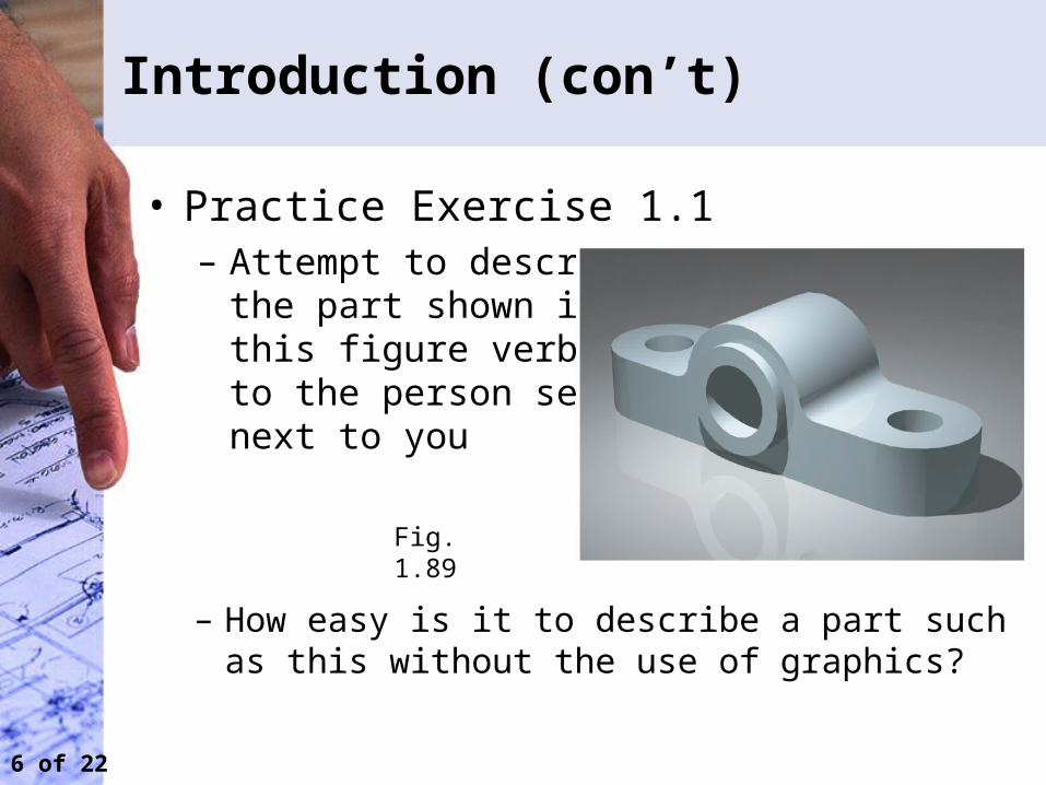
Introduction (con’t)
• Practice Exercise 1.1– Attempt to describe
the part shown in this figure verbally to the person seatednext to you
– How easy is it to describe a part such as this without the use of graphics?
Fig. 1.89

7 of 22
Introduction (con’t)
Traditional: A linear, segmented activity involving problem identification, preliminary ideas, design refinements, analysis, optimization, and documentation
Concurrent: A team activity involving coordination of the technical and non-technical functions of design and manufacturing within a business
The CAD database becomes a communication medium.
An evolving design process:
Fig. 1.12 Fig. 1.14 Fig. 1.15

8 of 22
What Will You Learn? (1.9)
Visualization Learn to mentally control visual information
Graphics theory
Learn to construct engineering geometry and master basic projection techniques
Standards Learn a set of rules that govern how parts are made and technical drawings are represented
Conventions Master commonly accepted practices and methods used for technical drawings
Tools Learn how to use drafting tools, both hand-held and computer tools
Applications Learn how technical graphics are used in engineering design
CE En 112
Manual Drafting
9 of 22
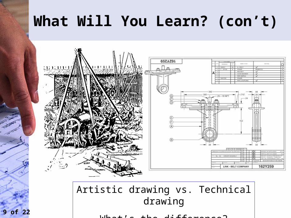
What Will You Learn? (con’t)
Artistic drawing vs. Technical drawing
What’s the difference?

10 of 22
What Will You Learn? (con’t)
Parallel projection Orthographic Axonometric (Isometric)
Multiview (& auxiliary)
Oblique Cabinet
Cavalier
Perspective projection Linear One-point
Two-point
11 of 22
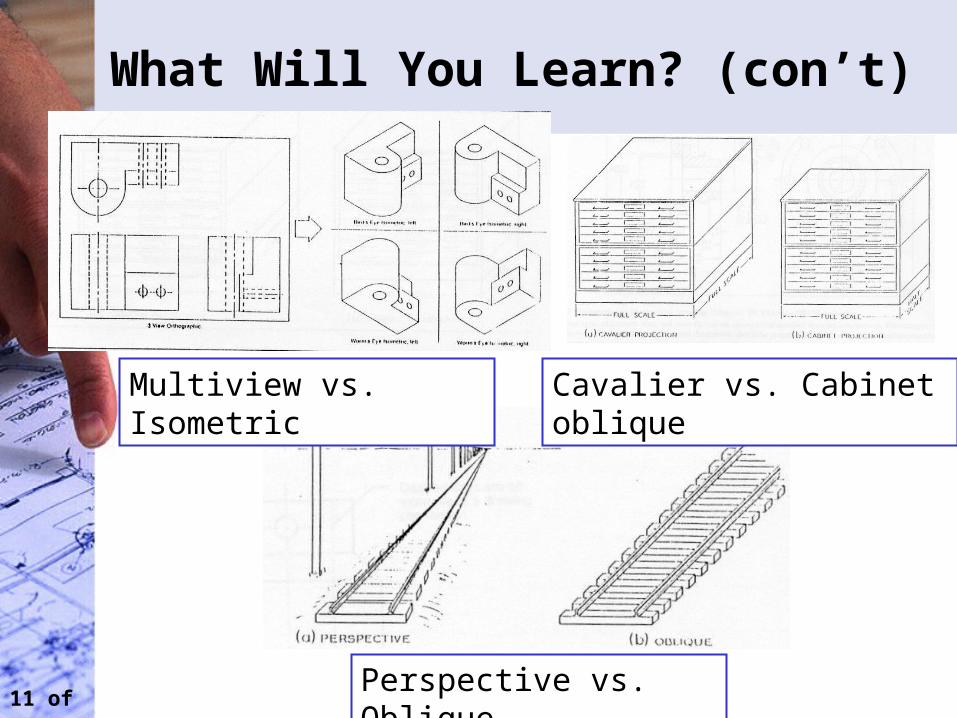
What Will You Learn? (con’t)
Multiview vs. Isometric
Cavalier vs. Cabinet oblique
Perspective vs. Oblique
12 of 22
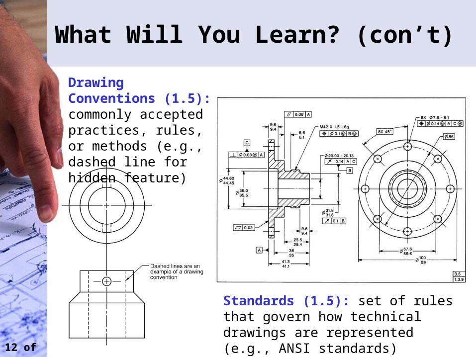
What Will You Learn? (con’t)
Drawing Conventions (1.5): commonly accepted practices, rules, or methods (e.g., dashed line for hidden feature)
Standards (1.5): set of rules that govern how technical drawings are represented (e.g., ANSI standards)
13 of 22
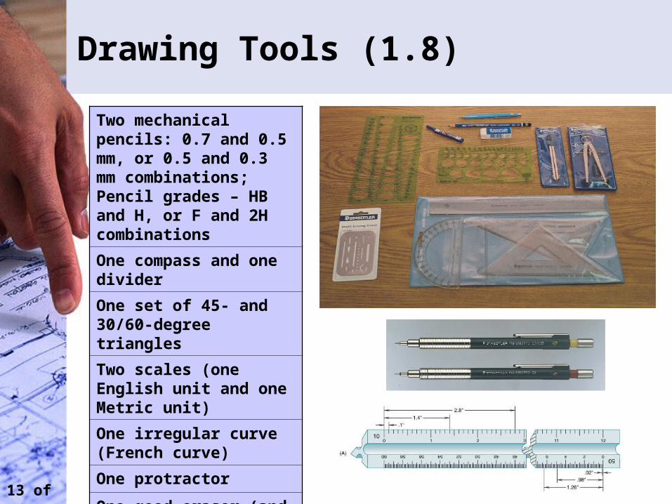
Drawing Tools (1.8)
Two mechanical pencils: 0.7 and 0.5 mm, or 0.5 and 0.3 mm combinations; Pencil grades – HB and H, or F and 2H combinations
One compass and one divider
One set of 45- and 30/60-degree triangles
Two scales (one English unit and one Metric unit)
One irregular curve (French curve)
One protractor
One good eraser (and if you can afford, one erasing shield)

14 of 22
Drawing Tools (con’t)
The use of drafting tools
15 of 22
Media (1.8.2)
• Media: surfaces upon which an engineer or technologist communicates graphical information. Different types include:– Tracing paper (a thin, translucent paper used for detail
drawings)– Vellum (tracing paper chemically treated to improve
translucency)– Polyester film (transparent, waterproof, and difficult to
tear, “Mylar”)
• The American National Standard Institute (ANSI) has established standard sheet sizes and title blocks for media used in technical drawings
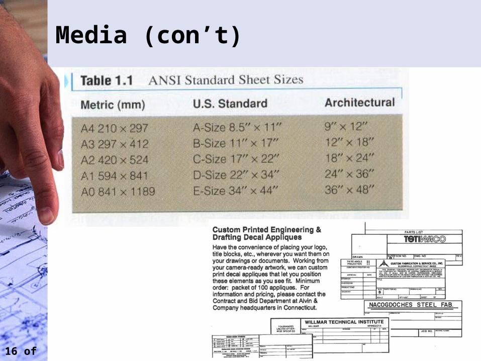
16 of 22
Media (con’t)
17 of 22
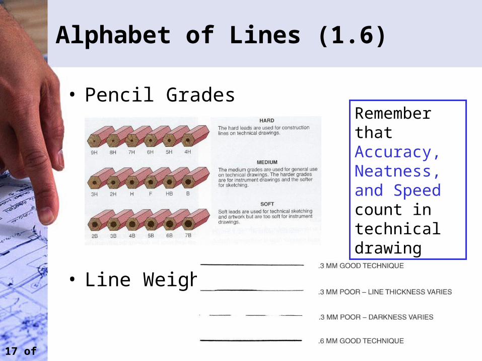
Alphabet of Lines (1.6)
• Pencil Grades
• Line Weight
Remember that Accuracy, Neatness, and Speed count in technical drawing
18 of 22
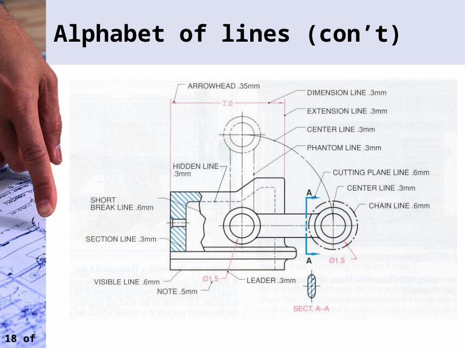
Alphabet of lines (con’t)
19 of 22
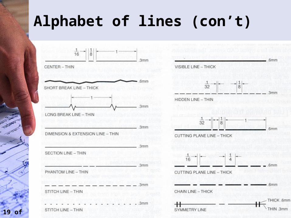
Alphabet of lines (con’t)
20 of 22
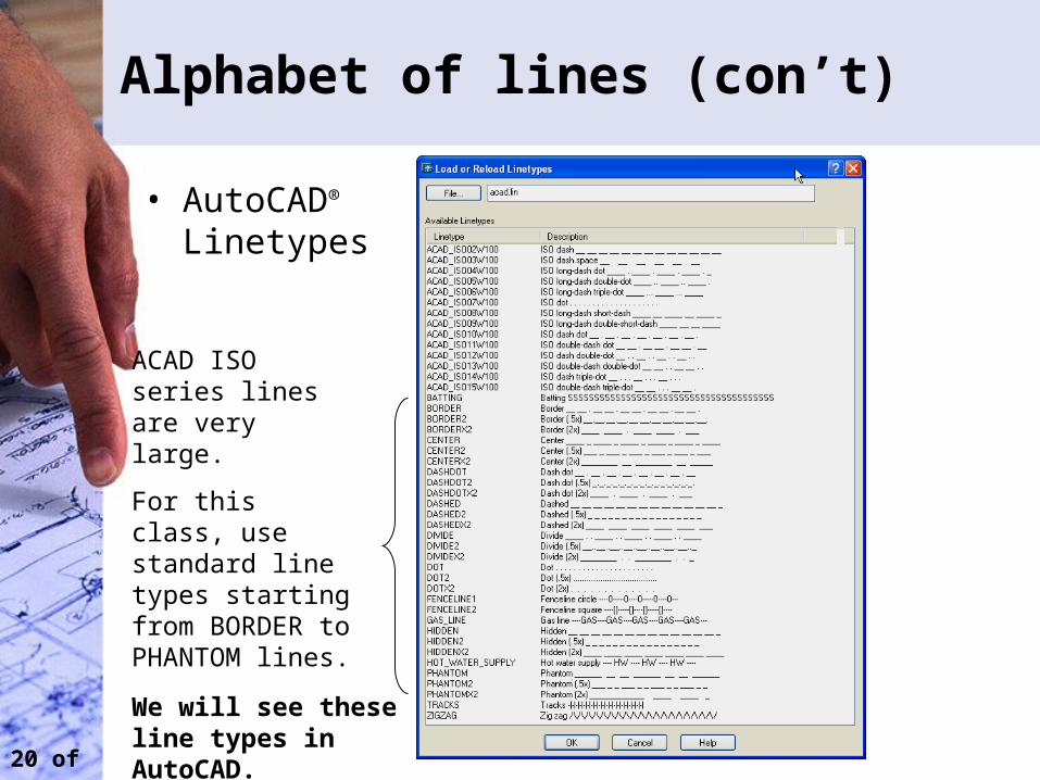
Alphabet of lines (con’t)
• AutoCAD®
Linetypes
ACAD ISO series lines are very large.
For this class, use standard line types starting from BORDER to PHANTOM lines.
We will see these line types in AutoCAD.
21 of 22
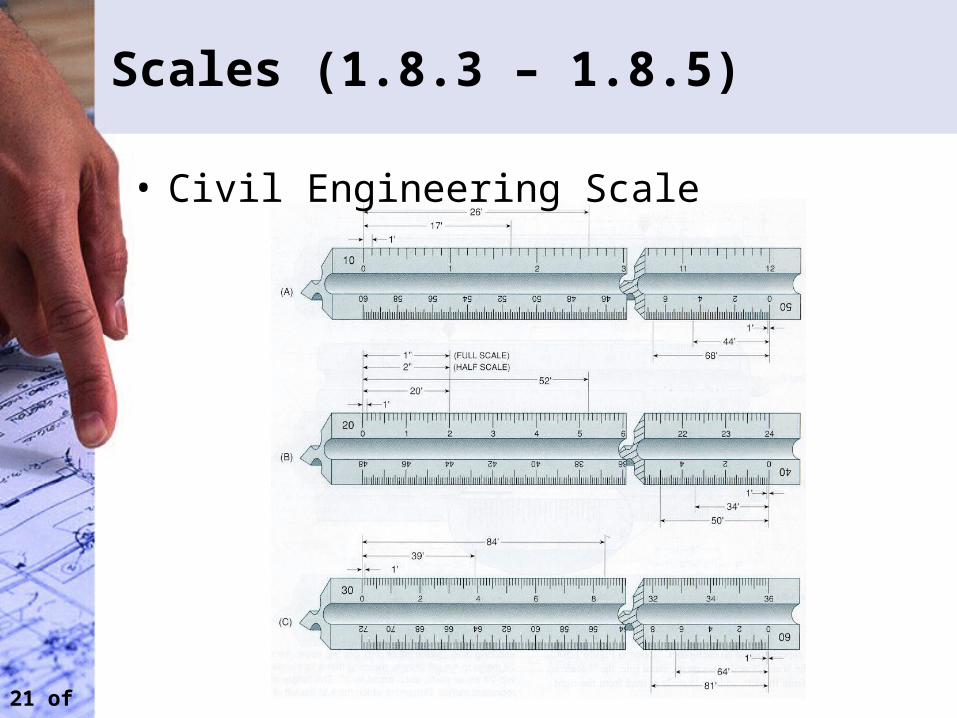
Scales (1.8.3 – 1.8.5)
• Civil Engineering Scale
22 of 22
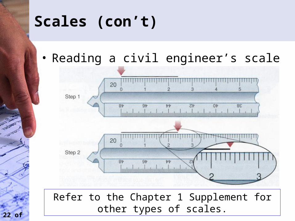
Scales (con’t)
• Reading a civil engineer’s scale
Refer to the Chapter 1 Supplement for other types of scales.
23 of 22
Next Manual Drafting Lecture (Jan 29)
• Purchase drafting tools needed for manual drafting portion of class if you have not done so
• Read Chapter 2 in the graphics communication book