CE 370 Screens. Water Treatment Coarse Bar Racks Coarse Bar Racks Clear space between bars is up to...
17
CE 370 CE 370 Screens Screens
-
Upload
hortense-price -
Category
Documents
-
view
213 -
download
0
Transcript of CE 370 Screens. Water Treatment Coarse Bar Racks Coarse Bar Racks Clear space between bars is up to...

CE 370CE 370
ScreensScreens

Water TreatmentWater Treatment
Coarse Bar RacksCoarse Bar RacksClear space between bars is up to 3 inches (75 Clear space between bars is up to 3 inches (75
mm)mm)Are used to retain large objects into water intakeAre used to retain large objects into water intake
Traveling RacksTraveling RacksLocated behind bar racksLocated behind bar racksHave openings of 3/8 to ½ inch (10-13 mm)Have openings of 3/8 to ½ inch (10-13 mm)Are used to prevent small particlesAre used to prevent small particles

Traveling Water Screens

Wastewater TreatmentWastewater Treatment
Manually cleaned screens Manually cleaned screens
Mechanically cleaned screensMechanically cleaned screens

Mechanically-cleaned Bar Screen

Manually Cleaned Bar ScreensManually Cleaned Bar Screens
Space between bars are 1 to 2 inches (25 to 50 Space between bars are 1 to 2 inches (25 to 50 mm)mm)
Mounted at 30 to 75Mounted at 30 to 75 angle to horizontal angle to horizontal (typically 30 to 45(typically 30 to 45))

Mechanically Cleaned Bar ScreensMechanically Cleaned Bar Screens
Bar spacing is 0.5 to 1.5 inches (12 to 38 mm)Bar spacing is 0.5 to 1.5 inches (12 to 38 mm) Mounted at 45 to 90Mounted at 45 to 90 with horizontal (typically with horizontal (typically
6060)) Cleaning is performed at time intervals or Cleaning is performed at time intervals or
when the head loss reaches a certain value (2 when the head loss reaches a certain value (2 inches or 50 mm)inches or 50 mm)

Design ParametersDesign Parameters
The approach channel should be straight for at The approach channel should be straight for at least 0.6 meter ahead of the screen to produce least 0.6 meter ahead of the screen to produce uniform flow through the screenuniform flow through the screen
Approach velocity should be at least 1.5 ft/sec Approach velocity should be at least 1.5 ft/sec (0.46 m/s) to prevent precipitation of debris(0.46 m/s) to prevent precipitation of debris
Velocity through bars should be less than 2 Velocity through bars should be less than 2 ft/sec (0.62 m/s) at design flowft/sec (0.62 m/s) at design flow
Velocity through bars should be not more than Velocity through bars should be not more than 3 ft/sec (0.91 m/s) at maximum flow 3 ft/sec (0.91 m/s) at maximum flow

Design ParametersDesign Parameters
A stand-by screen should be providedA stand-by screen should be provided Stop-gates slots are provided ahead and behind Stop-gates slots are provided ahead and behind
screens for maintenance reasonsscreens for maintenance reasons

Design EquationsDesign Equations
Head-loss across bar screens can be represented by:Head-loss across bar screens can be represented by:
hhLL = head loss, ft (m) = head loss, ft (m) VVaa = approach velocity ft/sec (m/s) = approach velocity ft/sec (m/s) VVbb = velocity through bar openings ft/sec (m/s) = velocity through bar openings ft/sec (m/s) g = acceleration due to gravityg = acceleration due to gravity
7.0
1
2
)( 22
g
VVh abL

ScreeningsScreenings
AmountAmountFor ½ inch spacing = 8 ftFor ½ inch spacing = 8 ft33 (60 m (60 m33) per million ) per million
gallons (million mgallons (million m33) of treated wastewater) of treated wastewaterFor 1.5 inch spacing = 1.5 ftFor 1.5 inch spacing = 1.5 ft33 (11.2 m (11.2 m33) per million ) per million
gallons (million mgallons (million m33) of treated wastewater) of treated wastewater
ManagementManagementDisposed in landfillsDisposed in landfills
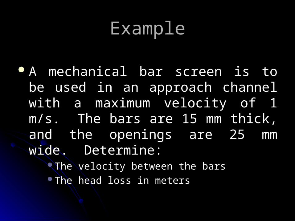
ExampleExample
A mechanical bar screen is to be used in an A mechanical bar screen is to be used in an approach channel with a maximum velocity of approach channel with a maximum velocity of 1 m/s. The bars are 15 mm thick, and the 1 m/s. The bars are 15 mm thick, and the openings are 25 mm wide. Determine:openings are 25 mm wide. Determine:
The velocity between the barsThe velocity between the barsThe head loss in metersThe head loss in meters

SolutionSolution Assume the channel has a width (W) and depth Assume the channel has a width (W) and depth
(D)(D) Net area of screen = WD [25 / (25+15) = Net area of screen = WD [25 / (25+15) =
(5/8)WD(5/8)WD Area of screen = WDArea of screen = WD Use continuity equationUse continuity equation
VVaa A Aaa = V = Vbb A Abb OR V OR Vbb = (V = (Vaa A Aaa) / A) / Abb
VVbb= 1 = 1 [WD / (5/8)WD] = (8 / 5 ) m/s [WD / (5/8)WD] = (8 / 5 ) m/s

SolutionSolution
Head LossHead Loss
7.0
1
2
)( 22
g
VVh abL
mg
hL 114.07.0
1
2
158 2
2

ShreddingShredding
Why ?Why ?Reduce size of particlesReduce size of particles
How ?How ?GrindersGrindersBarminutorsBarminutorscomminutorscomminutors
Fate of shredded solidsFate of shredded solidsReturn to wastewater flow downstream from screensReturn to wastewater flow downstream from screens


Comminutor Installation