![C:Documents and SettingslphFIDBQGHCCC SDX Series[1]rockmachinery.com/Parts/Idlers_SDX Series_CEMA E.pdf · SDX-Plus Series Super Duty Belt ... generation of the Continental SDX idler](https://static.fdocuments.us/doc/165x107/5afabf1c7f8b9a44658f70b7/cdocuments-and-settingslphfidbqghccc-sdx-series1-seriescema-epdfsdx-plus-series.jpg)
CDR Wireless / SDX Enabled Installation · PDF fileCDR Wireless / SDX Software Installation...
46
CDR Wireless / SDX Software Installation Guide Schick Technologies, Inc. 30-00 47 th Avenue Long Island City, NY 11101 (718) 937-5765 (718) 937-5962 (fax) PART NUMBER B1051504 REV. –
Transcript of CDR Wireless / SDX Enabled Installation · PDF fileCDR Wireless / SDX Software Installation...
CDR Wireless / SDX Software Installation Guide Schick Technologies, Inc. 30-00 47th Avenue Long Island City, NY 11101 (718) 937-5765 (718) 937-5962 (fax) PART NUMBER B1051504 REV. –

Copyright © 2004 by Schick Technologies, Inc. All Rights Reserved
October 12, 2004
Printed in the United States of America
This document was originally prepared in English
CDR and CDR Wireless are trademarks of Schick Technologies, Inc. CDR is a registered trademark and is covered by US Patent Numbers 5,912,942 and 6,134,298. Additional patents are pending.
Trademark designations used by other manufacturers and sellers may appear in this document also. Where Schick Technologies, Inc. was aware of a trademark claim, that information has been printed in caps or initial caps.

CDR Wireless/SDX Software Installation B1051504 Rev. –
i
Contents
1. Getting Started..............................................................................................1 1.1 Welcome .................................................................................................................................1 1.2 Important Setup Reminders ....................................................................................................3
2. CDR Wireless System.................................................................................4 2.1 Installation Overview..............................................................................................................4 2.2 Installation Procedures............................................................................................................5 2.3 Upgrade Overview ..................................................................................................................7 2.4 Upgrade Procedures ................................................................................................................8
3. SDX System ............................................................................................... 10 3.1 Installation Overview (CDR Wireless Sensors)....................................................................10 3.2 Installation Procedures (CDR Wireless Sensors)..................................................................11 3.3 Installation Overview (CDR2000 Sensors)...........................................................................13 3.4 Installation Procedures (CDR2000 Sensors).........................................................................14
4. CDR Wireless Sensor Setup................................................................... 16 4.1 Preparing the Sensor .............................................................................................................16 4.2 Turning on the Sensor ...........................................................................................................19 4.3 Positioning the Sensor...........................................................................................................19
5. Using the SDX Utility ................................................................................ 21 5.1 Introduction...........................................................................................................................21 5.2 USB Interface Test and Upgrade ..........................................................................................22 5.3 Sensor Upgrade.....................................................................................................................24 5.4 Receiver Upgrade..................................................................................................................24 5.5 Real-Time RF Environment Test ..........................................................................................25 5.6 Sensor Monitor......................................................................................................................28 5.7 Registering Wireless Sensors................................................................................................28
Appendix A. Base Station Positioning..................................................... 30 A-1 Mounting Options in the Docked Configuration ..................................................................30 A-2 Mounting Options in the Remote Configuration ..................................................................30
Index................................................................................................................... 38

ii B1051504 Rev. – CDR Wireless/SDX Software Installation
List of Figures Figure 1. CDR Wireless System...................................................................................................... 1 Figure 2. SDX System (with CDR2000 Sensor Connected) ........................................................... 2 Figure 3. Sample of SDX Utility Screen ....................................................................................... 23 Figure 4. USB Test Pattern............................................................................................................ 23 Figure 5. Sample of RF Environment Test Screen........................................................................ 25 Figure 6. Wireless Sensor Registration Dialog Box...................................................................... 29 Figure 7. Symbol designating active side of Antenna ................................................................... 30 Figure 8. Antenna / Receiver Positioning Guidelines ................................................................... 31 Figure 9. Undocking Units for Remote Positioning ...................................................................... 32 Figure 10. SDX USB Interface with Protective Panel Attached ................................................... 32 Figure 11. Antenna / Receiver with Protective Panel Attached .................................................... 32 Figure 12. SDX USB Interface Base ............................................................................................. 34 Figure 13. Antenna / Receiver Base .............................................................................................. 34 Figure 14. Remote Mounting Options........................................................................................... 37

CDR Wireless/SDX Enabled Installation B1051504 Rev. -
iii
List of Tables Table 1. Removing the Battery Pack from the Sensor .................................................................. 17 Table 2. Placing the Sensor in the Sensor Cradle.......................................................................... 18 Table 3. Securing the Battery Pack to the Sensor.......................................................................... 20 Table 4. Attaching the Antenna / Receiver Mounting Adapter ..................................................... 35

iv B1051504 Rev. – CDR Wireless/SDX Software Installation
Terms Used in this Document Base Station Antenna / Receiver Receives, via wireless RF link, the image acquired from the CDR Wireless Sensor and sends it to the CDR Wireless / SDX USB Interface. The device is powered from the computer’s USB port. CDR-W (CDR Wireless) Describes the wireless implementation of the CDR imaging system manufactured by Schick Technologies. CDR2000 Sensor Captures the image created when the Sensor is exposed to radiation from an SDX or other X-ray source and transmits the image over wired link. CDR Software (CDR DICOM for Windows) Provides advanced features for image acquisition, review, manipulation, printing, and storage. CDR Wireless Sensor Captures the image created when the Sensor is exposed to radiation from an SDX or other X-ray source and transmits the image over wireless RF link. CDR Wireless / SDX Interface Driver Name on the CD-ROM containing the driver for the SDX USB Interface. CDR Wireless / SDX USB Interface Communicates, via wired USB link, with attached computer hardware, enabling acquired images to be displayed on a computer monitor or other display system. The device is powered from the computer’s USB port. Also contains a Sensor configuration cradle used to set the CDR Wireless Sensor’s transmission channel and can be used for Sensor diagnosis. (A shortened name, SDX USB Interface, is used in text.) CDR Wireless / SDX Utility Configures and diagnoses CDR-W and SDX systems. (A shortened name, SDX Utility, is used in text.) RF (Radio Frequency) Alternating current waveform suitable for wireless transmission. RJ (Registered Jack) RJ-45 is the connector type at each end of the Category 5 cable used in the CDR-W system to convey data between the Antenna / Receiver and the SDX USB Interface when they are not connected to each other. SDX (Schick Dental X-ray) Describes the Intra-oral X-ray Source and supported hardware and software from Schick Technologies, Inc. SDX USB Interface Shortened name of CDR Wireless / SDX USB Interface. SDX Utility Shortened name of CDR Wireless / SDX Utility. USB (Universal Serial Bus) Plug and play interface between host computer and connected USB-compatible devices. Wireless / SDX Interface Name of CDR Wireless / SDX USB Interface in Windows Device Manager.

CDR Wireless/SDX Software Installation B1051504 Rev. –
1
1. Getting Started
Please Note: For a description of product names and acronyms, refer to the list of terms in the front of the manual.
1.1 Welcome
This document will help you install the driver for the SDX USB Interface and to use the SDX Utility to configure your CDR Wireless or SDX system. To install these files you will need the CDR Wireless / SDX Interface Driver CD-ROM. Section 2 describes how to install the driver and use the appropriate utility to configure the CDR Wireless System, which supports CDR Wireless Sensors, the SDX USB Interface, and the Antenna / Receiver. Section 3 describes how to install the driver and use the appropriate utility to configure the CDR SDX Intra-oral X-ray System, which supports CDR2000 and CDR Wireless Sensors, the SDX USB Interface, and the SDX Antenna and Receiver (located inside the SDX X-ray Head enclosure). The remaining sections of this document describe the operation of the CDR Wireless Sensor (Section 4) and the alternate mounting options for the external CDR Wireless Antenna / Receiver (Section 5) — this section does not apply to SDX systems.
Figure 1. CDR Wireless System
Antenna / Receiver
CDR Wireless Sensors
PC Workstation
SDX USB Interface
2 B1051504 Rev. – CDR Wireless/SDX Software Installation
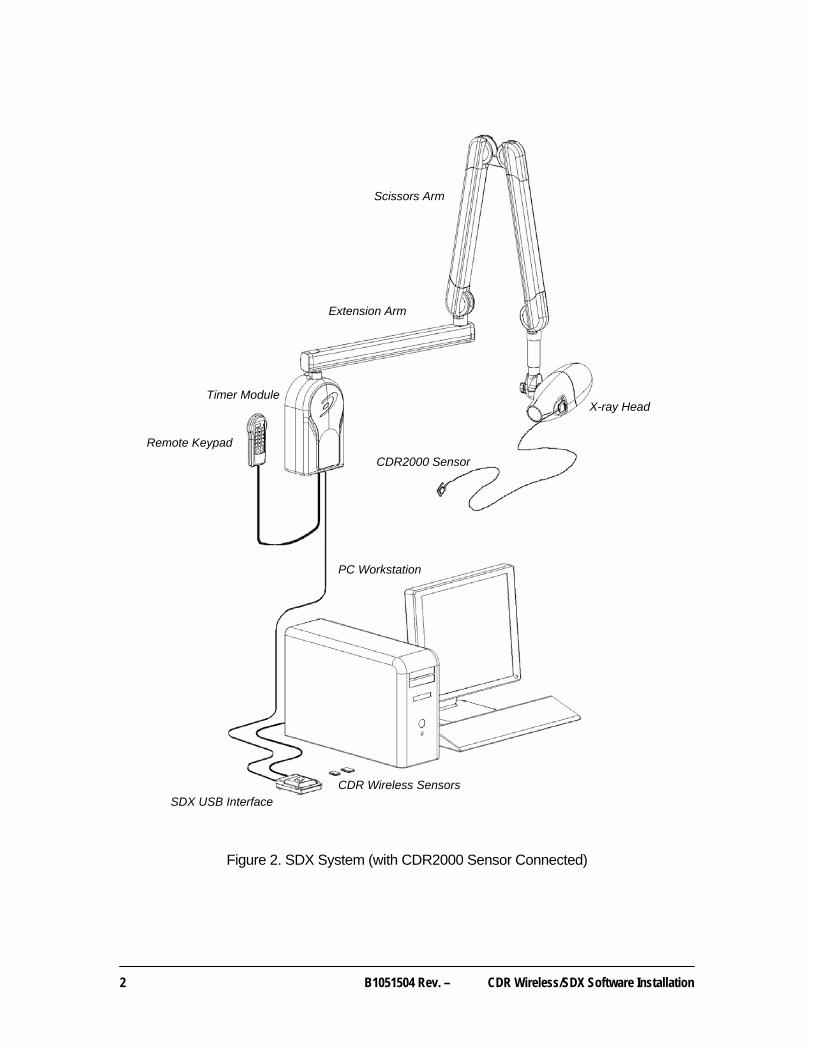
Figure 2. SDX System (with CDR2000 Sensor Connected)
X-ray Head
SDX USB Interface
CDR2000 Sensor
PC Workstation
Scissors Arm
Extension Arm
Remote Keypad
Timer Module
CDR Wireless Sensors
CDR Wireless/SDX Software Installation B1051504 Rev. –
3
1.2 Important Setup Reminders
1. Images acquired with your Wireless Sensor are transmitted to the Antenna / Receiver over a RF link. If active during image transmission, other devices that use radio frequency or microwave technology (wireless Local Area Networks, wireless telecommunication devices, microwave ovens) may interfere with the optimal performance of your CDR Wireless System. For best results, run the Real-Time RF Environment Test for information about potential RF interference, or turn off other wireless or microwave devices when using your Wireless Sensor. If these devices must remain on, they will cause less interference the further they are from the Antenna / Receiver.
2. Correct placement of the Antenna / Receiver with respect to the Wireless Sensor is essential. Be sure to follow the positioning information found in this document when establishing the optimal location for the Antenna / Receiver. As a general rule, place the Antenna / Receiver facing the patient, as close as practically possible to the patient chair where the Sensor will be used. Optimally, the distance between the Sensor and the Antenna / Receiver should not exceed 6 feet (1.8 meters). Refer to Appendix A and Figure 8 for guidelines on antenna positioning.
3. As with any dental X-ray procedure, stabilizing the Sensor in the correct intraoral position is critical for diagnostic quality images. Equally important is for the patient to remain completely still as X-ray images are acquired. Wireless Sensors are more sensitive to motion during the examination, so be sure to remind your patients as you take X-ray images.
4 B1051504 Rev. – CDR Wireless/SDX Software Installation
2. CDR Wireless System
Please Note: For a description of product names and acronyms, refer to the list of terms in the front of the manual.
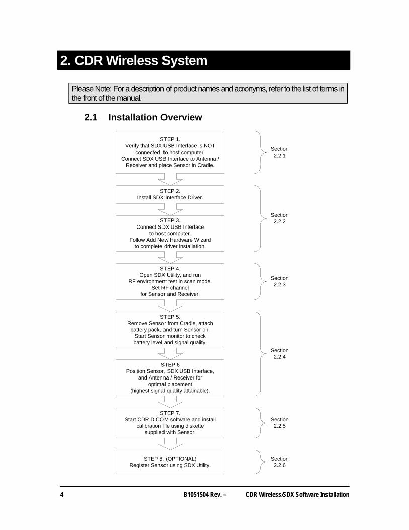
2.1 Installation Overview
STEP 1.Verify that SDX USB Interface is NOT
connected to host computer.Connect SDX USB Interface to Antenna /
Receiver and place Sensor in Cradle.
STEP 2.Install SDX Interface Driver.
STEP 4.Open SDX Utility, and run
RF environment test in scan mode.Set RF channel
for Sensor and Receiver.
STEP 5.Remove Sensor from Cradle, attach
battery pack, and turn Sensor on.Start Sensor monitor to checkbattery level and signal quality.
STEP 8. (OPTIONAL)Register Sensor using SDX Utility.
Section2.2.1
Section2.2.2
Section2.2.3
Section2.2.4
Section2.2.6
STEP 6Position Sensor, SDX USB Interface,
and Antenna / Receiver foroptimal placement
(highest signal quality attainable).
STEP 3.Connect SDX USB Interface
to host computer.Follow Add New Hardware Wizard
to complete driver installation.
STEP 7.Start CDR DICOM software and install
calibration file using diskettesupplied with Sensor.
Section2.2.5
CDR Wireless/SDX Software Installation B1051504 Rev. –
5
2.2 Installation Procedures
If you are installing our Wireless system for the first time, perform these instructions first. If you have been using our Wireless system, refer to the Upgrade User instructions. For the following procedure you will need the CDR Wireless / SDX Interface Driver CD provided with your system.
2.2.1 Preparing to Install Software
1. Exit CDR if it is running.
2. Verify that the SDX USB Interface is NOT connected to the host computer.
3. Verify that the SDX USB Interface is connected to the Receiver.
4. Verify that the Sensor is placed in the cradle of the SDX USB Interface. If you need more information on how to do this, refer to Section 4.
2.2.2 Installing Software
1. Insert the CDR Wireless / SDX Interface Driver CD into your CD-ROM or DVD drive.
2. Click Install SDX Driver when the CD browser window opens.
3. Click Next at the Welcome Screen.
4. Click Next at the Destination Folder Screen after confirming the path.
5. Click Install.
6. Click Finish.
7. Connect the SDX USB Interface to the computer.
8. Click Next when the Add New Hardware wizard starts for the SDX USB Interface device. When the Add New Hardware wizard ends, click Finish. (On Windows 2000 systems, this occurs automatically.)
9. Click Exit to close CD browser window.
2.2.3 Checking for RF Noise
1. Open the SDX Utility.
2. Click RF environment.
3. Select Scan.
4. After approximately 2 – 3 minutes, click Stop Logging.
5. Review the results and write down the recommended RF channel(s).
6. Close the RF environment window.

6 B1051504 Rev. – CDR Wireless/SDX Software Installation
2.2.4 Performing Final Checks
1. Click the Sensor / Receiver Read info buttons. Verify that the currently set RF channel is recommended. If not, click the Sensor arrow to select a recommended channel and make sure that the Match Channels checkbox is marked to automatically set the Receiver. Click Apply and then Yes. Both the Sensor and Receiver must be set to the same RF channel to communicate with each other.
2. Remove Sensor from cradle, attach battery pack, and turn Sensor on. If you need more information on how to do this, refer to Section 4.
3. Place Sensor on patient chair.
4. Click Sensor Monitor and check battery level and signal quality. For more information about the Sensor Monitor, refer to Section 5.
5. Place Receiver where signal quality is highest. Refer to Base Station positioning guidelines and options in Appendix A.
2.2.5 Loading the Wireless Sensor Calibration File
For this procedure you will need the CDR Wireless Calibration File disk provided with your CDR Wireless Sensor. This disk contains a unique calibration file for your Sensor. 1. Start CDR Dicom software.
2. Insert Sensor calibration diskette.
3. Click System > Options, select the Acquisition Modules tab, and click on X-ray.
4. Click Properties and select the Calibration tab.
5. Click Install New Calibration File.
6. Select the calibration file to install and click Open.
7. When the file has been copied to your system, click OK.
2.2.6 Register Wireless Sensor
1. Open the SDX Utility.
2. Click Register Sensors. (If you need more details, refer to Section 5.7.)
3. Remove battery pack and locate the Wireless Sensor serial number.
4. On the Register Wireless Sensors dialog box, select the serial number from the left pane and click on the arrow key ( ) to move it to the right pane.
5. Click OK to register the Wireless Sensor and close the dialog box.
CDR Wireless/SDX Software Installation B1051504 Rev. –
7
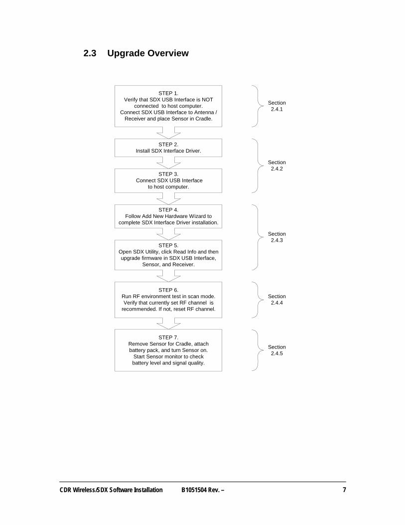
2.3 Upgrade Overview
STEP 1.Verify that SDX USB Interface is NOT
connected to host computer.Connect SDX USB Interface to Antenna /
Receiver and place Sensor in Cradle.
STEP 2.Install SDX Interface Driver.
STEP 4.Follow Add New Hardware Wizard to
complete SDX Interface Driver installation.
STEP 7.Remove Sensor for Cradle, attachbattery pack, and turn Sensor on.
Start Sensor monitor to checkbattery level and signal quality.
Section2.4.1
Section2.4.2
Section2.4.3
Section2.4.4
Section2.4.5
STEP 3. Connect SDX USB Interface
to host computer.
STEP 5.Open SDX Utility, click Read Info and thenupgrade firmware in SDX USB Interface,
Sensor, and Receiver.
STEP 6.Run RF environment test in scan mode.Verify that currently set RF channel is
recommended. If not, reset RF channel.

8 B1051504 Rev. – CDR Wireless/SDX Software Installation
2.4 Upgrade Procedures
If you have been using our Wireless system, these instructions will assist you with upgrading it. If you are installing the Wireless system for the first time, refer to the New User instructions. For the following procedure you will need the SDX Interface Driver CD provided with your system. This disk contains the driver for the SDX USB Interface and the upgrade and monitoring tools of the SDX Utility.
2.4.1 Preparing to Install Software
1. Exit CDR if it is running.
2. Verify that the SDX USB Interface is NOT connected to the host computer.
3. Verify that the SDX USB Interface is connected to the Receiver.
4. Verify that the Sensor is placed in the cradle of the SDX USB Interface. If you need more information on how to do this, refer to Section 4.
2.4.2 Installing Software
1. Insert the CDR Wireless / SDX Interface Driver CD into your CD-ROM or DVD drive.
2. Click Install SDX Driver when the CD browser window opens.
3. Click Next at the Welcome Screen.
4. Click Next at the Destination Folder Screen after confirming the path.
5. Click Install.
6. Click Finish.
7. Connect the SDX USB Interface to the computer.
8. Click Next when the Add New Hardware wizard starts for the SDX USB Interface device. When the Add New Hardware wizard ends, click Finish. (On Windows 2000 systems, this occurs automatically.)
9. Click Exit to close CD browser window.
CDR Wireless/SDX Software Installation B1051504 Rev. –
9
2.4.3 Upgrading Wireless System Firmware
1. Open the SDX Utility.
2. Click Read Info for the USB Interface.
• If any information is displayed in red, do the following:
• Click Upgrade CPLD.
• When upgrade is complete, verify that revision numbers are black.
3. Click Read Info for the Sensor.
• If any information is displayed in red, do the following:
• Click Upgrade CPLD.
• When upgrade is complete, verify that revision numbers are black.
4. Click Read Info for the Receiver.
• If any information is displayed in red, do the following:
• Click Upgrade Firmware.
• When upgrade is complete, verify that revision numbers are black.
2.4.4 Checking for RF Noise
1. Click RF environment.
2. Select Scan.
3. After approximately 2 – 3 minutes, click Stop Logging.
4. Review the results and write down the recommended RF channel(s).
5. Close the RF environment window.
2.4.5 Performing Final Checks
1. Click the Sensor / Receiver Read info buttons. Verify that the currently set RF channel is recommended. If not, click the Sensor arrow to select a recommended channel and make sure that the Match Channels checkbox is marked to automatically set the Receiver. Click Apply and then Yes. Both the Sensor and Receiver must be set to the same RF channel to communicate with each other.
2. Click Exit to close the SDX Utility.

10 B1051504 Rev. – CDR Wireless/SDX Software Installation
3. SDX System
Please Note: For a description of product names and acronyms, refer to the list of terms in the front of the manual.
3.1 Installation Overview (CDR Wireless Sensors)
STEP 1.
Verify that SDX USB Interface is NOTconnected to host computer.
Connect SDX USB Interface to SDXSystem and place Sensor in Cradle.
STEP 2.Install SDX Interface Driver.
STEP 4.Open SDX Utility, and run
RF environment test in scan mode.Set RF channel
for Sensor and Receiver.
STEP 5.Remove Sensor from Cradle, attach
battery pack, and turn Sensor on.Start Sensor monitor to checkbattery level and signal quality.
STEP 7. (OPTIONAL)Register Sensor using SDX Utility.
Section3.2.1
Section3.2.2
Section3.2.3
Section3.2.4
Section3.2.6
STEP 3.Connect SDX USB Interface
to host computer.Follow Add New Hardware Wizard to
complete driver installation.
STEP 6.Start CDR DICOM software and install
calibration file using diskettesupplied with Sensor.
Section3.2.5
CDR Wireless/SDX Software Installation B1051504 Rev. –
11
3.2 Installation Procedures (CDR Wireless Sensors)
If you are installing our Wireless system for the first time, perform these instructions first. If you have been using our Wireless system, refer to the Upgrade User instructions. For the following procedure you will need the CDR Wireless / SDX Interface Driver CD provided with your system.
3.2.1 Preparing to Install Software
1. Exit CDR if it is running.
2. Verify that the SDX USB Interface is NOT connected to the host computer.
3. Verify that the SDX USB Interface is connected to the SDX system by Category 5 network cable.
4. Verify that the Sensor is placed in the cradle of the SDX USB Interface. If you need more information on how to do this, refer to Section 4.
3.2.2 Installing Software
1. Insert the CDR Wireless / SDX Interface Driver CD into your CD-ROM or DVD drive.
2. Click Install SDX Driver when the CD browser window opens.
3. Click Next at the Welcome Screen.
4. Click Next at the Destination Folder Screen after confirming the path.
5. Click Install.
6. Click Finish.
7. Connect the SDX USB Interface to the computer.
8. Click Next when the Add New Hardware wizard starts for the SDX USB Interface device. When the Add New Hardware wizard ends, click Finish. (On Windows 2000 systems, this occurs automatically.)
9. Click Exit to close CD browser window.
3.2.3 Checking for RF Noise
1. Open the SDX Utility.
2. Click RF environment.
3. Select Scan.
4. After approximately 2 – 3 minutes, click Stop Logging.
5. Review the results and write down the recommended RF channel(s).
6. Close the RF environment window.
12 B1051504 Rev. – CDR Wireless/SDX Software Installation
3.2.4 Performing Final Checks
1. Click the Sensor / Receiver Read info buttons. Verify that the currently set RF channel is recommended. If not, click the Sensor arrow to select a recommended channel and make sure that the Match Channels checkbox is marked to automatically set the Receiver. Click Apply and then Yes. Both the Sensor and Receiver must be set to the same RF channel to communicate with each other.
2. Remove Sensor from cradle, attach battery pack, and turn Sensor on. If you need more information on how to do this, refer to Section 4.
3. Place Sensor on patient chair.
4. Click Sensor Monitor and check battery level and signal quality. For more information about the Sensor Monitor, refer to Section 5.
5. Place SDX X-ray Source Tubehead over Sensor to verify signal quality.
3.2.5 Loading the CDR Wireless Sensor Calibration File
For this procedure you will need the CDR Wireless Calibration File disk provided with your system. This disk contains a unique calibration file for your Wireless Sensor. 1. Start CDR Dicom software.
2. Insert Sensor calibration diskette.
3. Click System > Options, select the Acquisition Modules tab, and click on X-ray.
4. Click Properties and select the Calibration tab.
5. Click Install New Calibration File.
6. Select the calibration file to install and click Open.
7. When the file has been copied to your system, click OK.
3.2.6 Register Wireless Sensor
1. Open the SDX Utility.
2. Click Register Sensors. (If you need more details, refer to Section 5.7.)
3. Remove battery pack and locate the Wireless Sensor serial number.
4. On the Register Wireless Sensors dialog box, select the serial number from the left pane and click on the arrow key ( ) to move it to the right pane.
5. Click OK to register the Wireless Sensor and close the dialog box.
CDR Wireless/SDX Software Installation B1051504 Rev. –
13
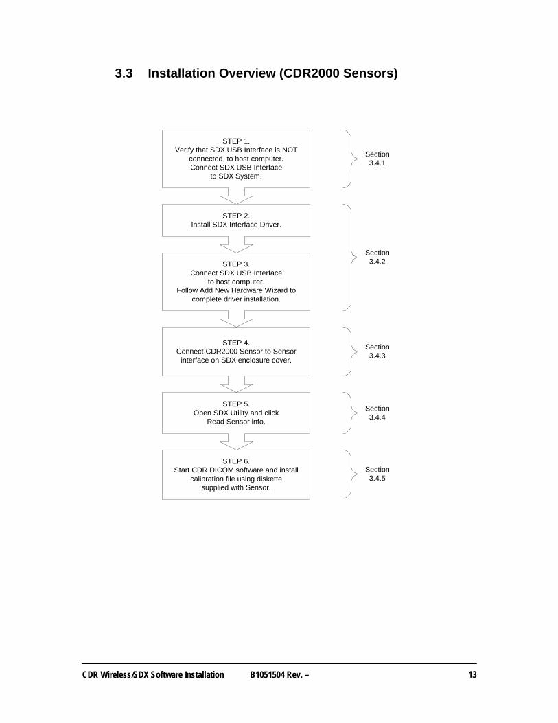
3.3 Installation Overview (CDR2000 Sensors)
STEP 1.Verify that SDX USB Interface is NOT
connected to host computer.Connect SDX USB Interface
to SDX System.
STEP 2.Install SDX Interface Driver.
STEP 4.Connect CDR2000 Sensor to Sensor
interface on SDX enclosure cover.
STEP 5.Open SDX Utility and click
Read Sensor info.
STEP 6.Start CDR DICOM software and install
calibration file using diskettesupplied with Sensor.
Section3.4.1
Section3.4.2
Section3.4.3
Section3.4.4
Section3.4.5
STEP 3.Connect SDX USB Interface
to host computer.Follow Add New Hardware Wizard to
complete driver installation.
14 B1051504 Rev. – CDR Wireless/SDX Software Installation
3.4 Installation Procedures (CDR2000 Sensors)
For this procedure you will need the CDR Wireless / SDX Interface Driver CD provided with your system. This disk contains the driver for the SDX USB Interface and the upgrade and monitoring tools of the SDX Utility.
3.4.1 Preparing to Install Software
1. Exit CDR if it is running.
2. Verify that the SDX USB Interface is NOT connected to the host computer.
3. Verify that the SDX USB Interface is connected to the SDX system by Category 5 network cable.
3.4.2 Installing Software
1. Insert the CDR Wireless / SDX Interface Driver CD into your CD-ROM or DVD drive.
2. Click Install SDX Driver when the CD browser window opens.
3. Click Next at the Welcome Screen.
4. Click Next at the Destination Folder Screen after confirming the path.
5. Click Install.
6. Click Finish.
7. Connect the SDX USB Interface to the computer.
8. Click Next when the Add New Hardware wizard starts for the SDX USB Interface device. When the Add New Hardware wizard ends, click Finish. (On Windows 2000 systems, this occurs automatically.)
9. Click Exit to close CD browser window.
3.4.3 Connect CDR2000 Sensor to SDX System
1. Locate the CDR2000 Sensor interface on the SDX X-ray Head enclosure covers.
2. Connect the CDR2000 Sensor.
3.4.4 Performing Final Checks
1. Open the SDX Utility.
2. Click the Sensor Read info button.
3. Verify that the information for the currently connected Sensor is correct.

CDR Wireless/SDX Software Installation B1051504 Rev. –
15
3.4.5 Loading the Sensor Calibration File
For this procedure you will need the CDR Sensor Calibration File disk provided with your CDR 2000 Sensor. This disk contains a unique calibration file for your Wireless Sensor. 1. Start CDR Dicom software.
2. Insert Sensor calibration diskette.
3. Click System > Options, select the Acquisition Modules tab, and click on X-ray.
4. Click Properties and select the Calibration tab.
5. Click Install New Calibration File.
6. Select the calibration file to install and click Open.
7. When the file has been copied to your system, click OK.

16 B1051504 Rev. – CDR Wireless/SDX Software Installation
4. CDR Wireless Sensor Setup
Please Note: For a description of product names and acronyms, refer to the list of terms in the front of the manual.
Before using the Wireless Sensor, it must be configured to transmit on one of three RF channels, as follows:
4.1 Preparing the Sensor
To configure the Wireless Sensor, perform the following steps. You need to perform this procedure before the Sensor is used the very first time and when you want to change the Sensor’s channel to avoid interference.
Please Note: To perform the next step, follow the directions in Table 1 to remove the battery package properly from the Sensor.
1. Remove the battery pack from the Sensor by sliding and lifting it away from Sensor.
2. Disconnect the USB cable from the SDX USB Interface.
Please Note: To perform the next step, follow the directions in Table 2 to place the Sensor properly in the cradle area.
3. Place the Sensor with contacts side down into Sensor cradle located under the lid of the SDX USB Interface.
4. Reconnect the USB cable to the SDX USB Interface.

CDR Wireless/SDX Software Installation B1051504 Rev. –
17
Table 1. Removing the Battery Pack from the Sensor
Step Instruction Illustration
1. Locate the orientation symbol on the battery package
2. Slide battery along Sensor guides in the opposite direction of the orientation symbol
3.
Lift up and remove the battery pack and store it in a proper location
Please note: When detached from the Sensor, place the battery pack on its back with the terminals facing upwards. Ensure that no conductive object contacts the battery terminals to prevent accidental discharge.
18 B1051504 Rev. – CDR Wireless/SDX Software Installation
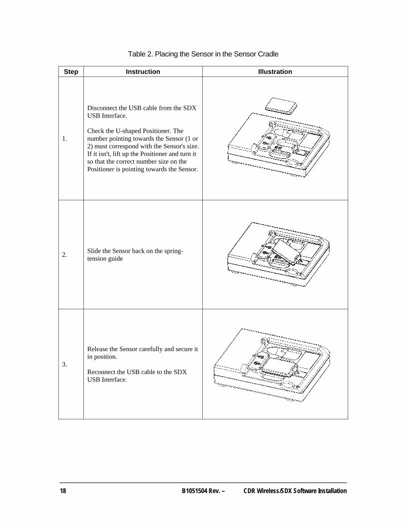
Table 2. Placing the Sensor in the Sensor Cradle
Step Instruction Illustration
1.
Disconnect the USB cable from the SDX USB Interface. Check the U-shaped Positioner. The number pointing towards the Sensor (1 or 2) must correspond with the Sensor's size. If it isn't, lift up the Positioner and turn it so that the correct number size on the Positioner is pointing towards the Sensor.
2. Slide the Sensor back on the spring-tension guide
3.
Release the Sensor carefully and secure it in position. Reconnect the USB cable to the SDX USB Interface.

CDR Wireless/SDX Software Installation B1051504 Rev. –
19
4.2 Turning on the Sensor
Please Note: To perform the next step, follow the directions in Table 3 to place the battery package correctly on the Sensor .
1. Reconnect the battery pack, following the alignment guides along the Sensor. The battery pack and Sensor are keyed to each other so that when they are positioned correctly, the battery pack will slide along the guides and snap easily into place.
2. Press the pushbutton switch located on the battery package to toggle the Sensor on and off. Sensor battery status and RF channel selection are displayed on the dual LEDs when the Sensor is turned on. Refer to the CDR Wireless / SDX Software User Guide for battery status and RF channel codes.
4.3 Positioning the Sensor
1. Place the Wireless Sensor on or close to the patient chair and adjust the Antenna so it is within line of sight of the Wireless Sensor. Details and illustrations regarding Antenna placement can be found in Appendix A.
2. Turn on the Sensor (if it is not on already) and open the Sensor Monitor. (The icon for the Sensor Monitor can be found in your System Tray. If the icon is not present, click on the Sensor Monitor button to display it.)
3. Check the battery level and the signal quality values. Pivot and rotate the Antenna, with the active side (identified by symbol) facing the patient, to achieve the optimal signal quality in your operatory.
4. Keep in mind that there are no perfect measurements, but try to obtain and maintain the highest levels possible for each.

20 B1051504 Rev. – CDR Wireless/SDX Software Installation
Table 3. Securing the Battery Pack to the Sensor
Step Instruction Illustration
1.
Locate the orientation symbol on the battery package and make sure it is facing the same direction as the corresponding symbol on the Sensor
2. Position battery along Sensor guides
3.
Slide battery package along Sensor guides in the same direction as the orientation symbol until it locks into place. Do not attempt to snap the battery pack down onto the Sensor. This may damage the Sensor and / or battery pack.
CDR Wireless/SDX Software Installation B1051504 Rev. –
21
5. Using the SDX Utility
Please Note: For a description of product names and acronyms, refer to the list of terms in the front of the manual.
5.1 Introduction
The SDX Utility is installed during the CDR Wireless Sensor Software setup program. This tool is used to:
• Select the Sensor and Receiver RF channel
• Perform firmware upgrades
• Perform diagnostic tests
• Register Wireless Sensors
These features are accessible from the SDX Utility screen, a sample of which is shown in Figure 3. Although the SDX Utility is intended principally for troubleshooting RF interference or Sensor-to-Receiver communication problems that result either in no images or images with poor quality, the Register Sensors feature can be useful at any time when managing multiple Wireless Sensors.
Please Note: Registering and locking Sensors applies only to CDR Wireless Sensors, and not to CDR2000 Sensors.
Registered Sensors can be locked, using the Sensor Monitor, to particular workstations. Locking Wireless Sensors serves to “lock-in” a particular Wireless Sensor with a workstation, enabling customers to take more control of their Wireless Sensors, and providing better workflow in practices where multiple Wireless Sensors are in operation at the same time and (possibly) on the same channel. Refer to Section 5.7 for more information about registering Wireless Sensors. More information on Sensor locking can be found in the CDR Wireless / SDX Software User Guide.

22 B1051504 Rev. – CDR Wireless/SDX Software Installation
5.2 USB Interface Test and Upgrade
5.2.1 USB Interface Test Description
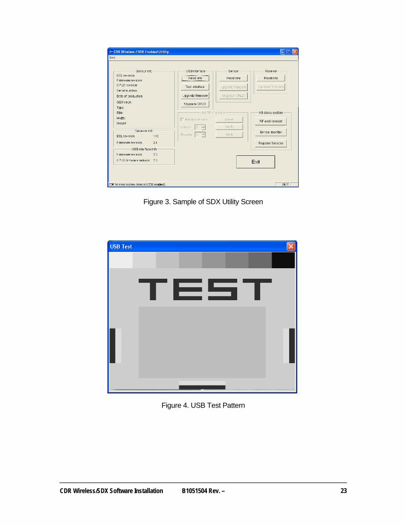
The USB Interface Test checks the connection between the SDX USB Interface and the host computer. During this check, a gray test pattern will appear, which should be reviewed for clarity and contrast (Figure 4). A good test pattern will have distinct shades of gray that are easy to distinguish. A poor test pattern will have random and unrelated lines or other image artifacts. A poor test pattern suggests a problem with the USB cable, USB port, or possibly the SDX USB Interface itself.
5.2.2 USB Interface Test Procedure
1. Please close the CDR DICOM program application (if running).
2. Verify that the SDX USB Interface is connected to the host computer.
3. Open the SDX Utility.
4. Click the USB Interface Test interface button.
5. After a momentary pause, a test pattern is displayed. The orange indicator on the SDX USB Interface blinks as the test pattern scrolls.
5.2.3 USB Interface Upgrade Description
Field updates to the SDX USB Interface can be accomplished by installing new USB Interface firmware and new USB Interface CPLD firmware.
5.2.4 USB Interface Upgrade Procedure
1. Please close the CDR DICOM program application (if running).
2. Verify that the SDX USB Interface is connected to the host computer.
3. Open the SDX Utility.
4. Click the USB Interface Read info button and check the USB Interface info box.
5. If the Firmware revision version is in red letters, click the Upgrade firmware button.
6. If the CPLD firmware revision is in red letters, click the Upgrade CPLD button.
CDR Wireless/SDX Software Installation B1051504 Rev. –
23
Figure 3. Sample of SDX Utility Screen
Figure 4. USB Test Pattern
24 B1051504 Rev. – CDR Wireless/SDX Software Installation
5.3 Sensor Upgrade
5.3.1 Sensor Upgrade Description
Field updates to the CDR Wireless Sensor can be accomplished by installing new Sensor firmware and new Sensor CPLD firmware.
5.3.2 Sensor Upgrade Procedure
1. Please close the CDR DICOM program application (if running).
2. Verify that the SDX USB Interface is connected to the host computer.
3. Verify that the Sensor is placed inside the SDX USB Interface cradle.
4. Open the SDX Utility.
5. Click the Sensor Read info button and check the Sensor info box.
6. If the CPLD firmware revision is in red letters, click the Upgrade CPLD button.
7. If the Firmware revision version is in red letters, click the Upgrade firmware button.
5.4 Receiver Upgrade
5.4.1 Receiver Upgrade Description
Field updates to the Receiver can be accomplished by installing new Receiver firmware.
5.4.2 Receiver Upgrade Procedure
1. Please close the CDR DICOM program application (if running).
2. Verify that the SDX USB Interface is connected to the host computer.
3. Verify that the Receiver is connected to the SDX USB Interface.
4. Open the SDX Utility.
5. Click the Receiver Read info button and check the Receiver info box
6. If the Firmware revision version is in red letters, click the Upgrade firmware button.
CDR Wireless/SDX Software Installation B1051504 Rev. –
25
5.5 Real-Time RF Environment Test
5.5.1 RF Environment Test Description
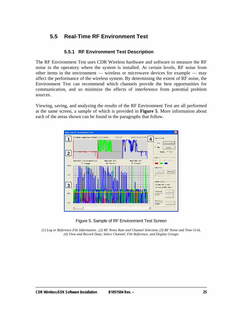
The RF Environment Test uses CDR Wireless hardware and software to measure the RF noise in the operatory where the system is installed. At certain levels, RF noise from other items in the environment — wireless or microwave devices for example — may affect the performance of the wireless system. By determining the extent of RF noise, the Environment Test can recommend which channels provide the best opportunities for communication, and so minimize the effects of interference from potential problem sources. Viewing, saving, and analyzing the results of the RF Environment Test are all performed at the same screen, a sample of which is provided in Figure 5. More information about each of the areas shown can be found in the paragraphs that follow.
Figure 5. Sample of RF Environment Test Screen
(1) Log or Reference File Information , (2) RF Noise Rate and Channel Selection, (3) RF Noise and Time Grid, (4) View and Record Data; Select Channel; File Reference, and Display Groups
1
2
3
4

26 B1051504 Rev. – CDR Wireless/SDX Software Installation
5.5.2 Getting Channel Recommendations in Scan Mode
Scan mode checks all three channels used by the Wireless Sensor and recommends the ones that offer optimal opportunities for communication. We recommend Scan mode for all new installations of the wireless system, or for any current wireless system which has not run the RF Environment Test previously. To operate the RF Environment Test in Scan mode, perform the following steps. 1. At the SDX Utility screen, click RF environment.
2. Select Scan.
3. After 2 - 3 minutes, click Stop Logging.
4. Review the results and write down the recommended RF channel(s).
5. Close the RF environment window.
6. Click the Sensor / Receiver Read info buttons. Verify that the currently set RF channel is recommended. If not, click the Sensor arrow to select a recommended channel and make sure that the Match Channels checkbox is marked to automatically set the Receiver. Click Apply and then Yes. Both the Sensor and Receiver must be set to the same RF channel to communicate with each other
5.5.3 Getting Data on a Single RF Channel
In the event of performance issues that affect image acquisition after the wireless system is installed, we suggest running the RF Environment Test again. New sources of RF interference may be present since the installation, and communication may improve by selecting a different channel. To operate the RF Environment Test in single channel mode, perform the following steps. 1. At the SDX Utility screen, write down the currently set RF channel.
2. Click RF environment.
3. Click the number (1, 2, or 3) corresponding to the currently set RF channel.
4. After 2 to 3 minutes, click Stop Logging.
5. Review the results for the selected RF channel.
6. If the RF channel is recommended, no other changes are needed. If performance issues persist, perform the Scan mode procedure (above).
CDR Wireless/SDX Software Installation B1051504 Rev. –
27
5.5.4 Changing the Display
To better understand the information collected by the RF Environment Test, it may be necessary to change or customize the way the data is displayed. One way to do this, especially when collecting data for several minutes, is to adjust the time base measurement so that more data can be displayed on the grid area. These changes can be made either during real-time measurements, or afterwards, when the test is complete. 1. At the RF environment window, go to the Display Controls group.
2. Click the plus (+) sign to increase the time interval, and decrease scrolling.
3. Click the minus (-) sign to decrease the time interval, and increase scrolling.
It possible to replay the results from the RF Environment Test and to pause (“Freeze”) and resume (“Unfreeze”) the replay at any time.
5.5.5 Saving and Comparing Display Results
Whenever the Live option is selected, a log file of those results is automatically saved to your computer. The log files are collected in a folder named “RFFiles” and can be found under Schick Technologies \ Shared Files. The files themselves are prefixed by year and date information (for example, “20040329” would be March 29, 2004) and are suffixed by “RF” and the number of channels (RF1, RF2, RF3, or RF123 - Scan mode) for which data was collected. The results of any RF Environment Test can also be saved as a reference file. Reference files are intended primarily for troubleshooting when comparing historical and current data. As an example, a reference file could be created to capture the intermittent presence of RF noise on a particular channel, a condition which, when compared with recent data, might be helpful in tracking the source of the interference. Reference Files are stored in the same location as log files, and are identified by a “REF” extension.
28 B1051504 Rev. – CDR Wireless/SDX Software Installation
5.6 Sensor Monitor
5.6.1 Sensor Monitor Description
The Sensor Monitor provides real-time reporting of the Wireless Sensor and shows the status of several elements required for proper operation, including battery level and signal quality. For additional information regarding the use of the Sensor Monitor, please refer to the CDR Wireless / SDX Software User Guide.
5.6.2 Getting Status Information
1. At the SDX Utility screen, click Sensor Monitor.
2. If you have not done so already, remove the Sensor from the cradle, attach the battery pack, and turn the Sensor on. If you need more information on how to do this, refer to Section 3.
3. Place Sensor on patient chair.
4. Click Sensor Monitor and check battery level and signal quality. Keep in mind that there are no perfect measurements, but try to obtain and maintain the highest levels attainable for each.
5.7 Registering Wireless Sensors
5.7.1 Registration Description
Registering a Wireless Sensor is the first step in a two-step process that enables Wireless Sensors to be locked to particular workstations. Only registered Wireless Sensors can be locked, so we recommend that you register them as soon as you can, if you use multiple Wireless Sensors at the same time in your practice. The second step in the process is to select a particular Wireless Sensor from a list of Registered Wireless Sensors and lock it to the current workstation, using the Sensor Monitor.
Please Note: Registering and locking Sensors applies only to CDR Wireless Sensors, and not to CDR2000 Sensors.
As we have said in the Introduction to this section, locking Wireless Sensors to specific workstations provides more customer control in practices where several Wireless Sensors can be in use, possibly on the same RF channel, at the same time. More information on Sensor locking can be found in the CDR Wireless / SDX Software User Guide.

CDR Wireless/SDX Software Installation B1051504 Rev. –
29
5.7.2 Registration Procedure
Wireless Sensor registration is performed entirely within one single dialog box (shown in Figure 6) and consists of moving Wireless Sensors, identified by serial number and size, from the left window (Unregistered) to the right window (Registered). 1. At the SDX Utility screen, click Register Sensors.
2. When the dialog box opens, a list of all Sensor calibration files found on the workstation (including those for CDR2000 Sensors, if any) are displayed on the left side.
3. Check the serial number of the Wireless Sensor(s) you wish to register on this workstation. If a battery pack is attached, remove it to read the serial number.
4. Select each Wireless Sensor and press the ( ) button to move it to the right side.
5. Click OK.
Figure 6. Wireless Sensor Registration Dialog Box

30 B1051504 Rev. – CDR Wireless/SDX Software Installation
Appendix A. Base Station Positioning
Please Note: The side of the Antenna indicated by the symbol shown in Figure 7 identifies the active side of the Antenna. This side must face the patient. For a description of product names and acronyms, refer to the list of terms in the front of the manual.
Figure 7. Symbol designating active side of Antenna
The SDX USB Interface and Antenna / Receiver can be surface-, wall-, or ceiling-mounted as one unit (docked) or separately (undocked) to achieve the best performance.
A-1 Mounting Options in the Docked Configuration
To position the SDX USB Interface and the Antenna / Receiver in their shipped (docked) arrangement, refer to Section A-2-A.
A-2 Mounting Options in the Remote Configuration
To release the SDX USB Interface and the Antenna / Receiver from their docked arrangement and to position them remotely, refer to Section A-2-B.
A-2-A Docked Mounting Option
1. Choose a convenient location for the SDX USB Interface and the Antenna / Receiver, keeping in mind that:
a. You may need to periodically access the Sensor cradle for channel configuration.
b. The Antenna / Receiver must face the front of the patient and be within 6 feet (1.8 meters) of the area where the Wireless Sensor will be used (Figure 8).
2. Using the USB cable provided with your system, connect the cable from the SDX USB Interface to the PC workstation. If you need a different USB cable from the one supplied with your system, refer to the CDR Wireless / SDX Software User Guide for compatible cable lengths and markings.

CDR Wireless/SDX Software Installation B1051504 Rev. –
31
A-2-B Remote Mounting Options
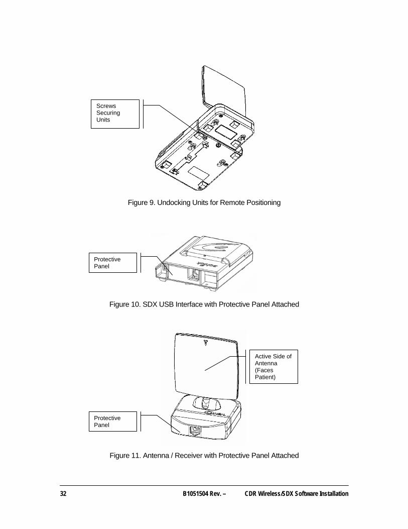
The Antenna / Receiver and SDX USB Interface can be wall-mounted as one unit (docked) or separately (undocked) to achieve the best performance. When the two modules are positioned separately, you will need to add the protective covers provided with your system for the Antenna / Receiver and SDX USB Interface. These covers will attach to the connector panels of each module. 1. Using a Phillips screwdriver, remove the two screws that secure the Antenna /
Receiver and SDX USB Interface during shipment. (See Figure 9.)
2. Using a Phillips screwdriver, secure the protective cover to the SDX USB Interface with one (#6 x 3/4) screw (provided). (See Figure 10.)
3. Using a Phillips screwdriver, secure the protective cover to the Antenna / Receiver with two (#6 x 3/4) screws (provided). (See Figure 11.)
Figure 8. Antenna / Receiver Positioning Guidelines
(Distance between Sensor and Antenna / Receiver should be 6 feet (1.8 meters) or less)
Not Recommended
Marginal
Acceptable
Recommended
32 B1051504 Rev. – CDR Wireless/SDX Software Installation
Figure 9. Undocking Units for Remote Positioning
Figure 10. SDX USB Interface with Protective Panel Attached
Figure 11. Antenna / Receiver with Protective Panel Attached
Protective Panel
Protective Panel
Active Side of Antenna (Faces Patient)
Screws Securing Units
CDR Wireless/SDX Software Installation B1051504 Rev. –
33
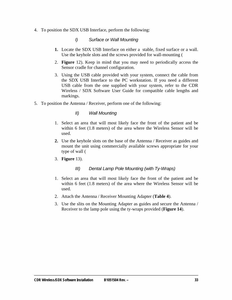
4. To position the SDX USB Interface, perform the following:
I) Surface or Wall Mounting
1. Locate the SDX USB Interface on either a stable, fixed surface or a wall. Use the keyhole slots and the screws provided for wall-mounting (
2. Figure 12). Keep in mind that you may need to periodically access the Sensor cradle for channel configuration.
3. Using the USB cable provided with your system, connect the cable from the SDX USB Interface to the PC workstation. If you need a different USB cable from the one supplied with your system, refer to the CDR Wireless / SDX Software User Guide for compatible cable lengths and markings.
5. To position the Antenna / Receiver, perform one of the following:
II) Wall Mounting
1. Select an area that will most likely face the front of the patient and be within 6 feet (1.8 meters) of the area where the Wireless Sensor will be used.
2. Use the keyhole slots on the base of the Antenna / Receiver as guides and mount the unit using commercially available screws appropriate for your type of wall (
3. Figure 13).
III) Dental Lamp Pole Mounting (with Ty-Wraps)
1. Select an area that will most likely face the front of the patient and be within 6 feet (1.8 meters) of the area where the Wireless Sensor will be used.
2. Attach the Antenna / Receiver Mounting Adapter (Table 4).
3. Use the slits on the Mounting Adapter as guides and secure the Antenna / Receiver to the lamp pole using the ty-wraps provided (Figure 14).

34 B1051504 Rev. – CDR Wireless/SDX Software Installation
Figure 12. SDX USB Interface Base
Figure 13. Antenna / Receiver Base
Screw holes used to secure Antenna (1 of 2)
Raised Non-Skid Pad (1 of 4)
Slot to Secure Base (1 of 2)
Cable Management Guide
Raised Non-Skid Pad (1 of 3)
Slot to Secure Base (1 of 2)
Screw holes used to secure USB Interface (1 of 2)
CDR Wireless/SDX Software Installation B1051504 Rev. –
35
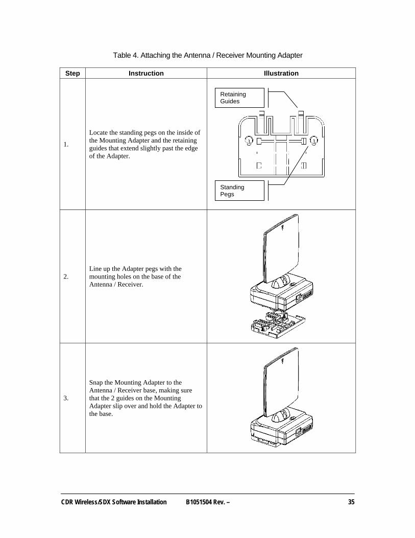
Table 4. Attaching the Antenna / Receiver Mounting Adapter
Step Instruction Illustration
1.
Locate the standing pegs on the inside of the Mounting Adapter and the retaining guides that extend slightly past the edge of the Adapter.
2. Line up the Adapter pegs with the mounting holes on the base of the Antenna / Receiver.
3.
Snap the Mounting Adapter to the Antenna / Receiver base, making sure that the 2 guides on the Mounting Adapter slip over and hold the Adapter to the base.
Retaining Guides
Standing Pegs
36 B1051504 Rev. – CDR Wireless/SDX Software Installation
IV) Surface Mounting (with Velcro Strips)
1. Select an area that will most likely face the front of the patient and be within 6 feet (1.8 meters) of the area where the Wireless Sensor will be used.
2. Attach the Antenna / Receiver Mounting Adapter (Table 4).
3. Use the flat area on the Mounting Adapter as a guide and secure the Antenna / Receiver to any flat surface using the Velcro strips provided (Figure 14).
V) Suspended Ceiling Mounting (with Clips)
1. Select an area that will most likely face the front of the patient and be within 6 feet (1.8 meters) of the area where the Wireless Sensor will be used.
2. Use the recessed area along the inside of the Adapter as a guide to place the Adapter on the ceiling T-bar. Using commercially available ceiling clips, secure the Adapter to the ceiling (Figure 14).
3. Attach the Antenna / Receiver Mounting Adapter (Table 4).
6. Using standard computer network Category 5 cable, connect the SDX USB Interface to the Antenna / Receiver.
7. Using the USB cable provided with your system, connect the cable from the SDX USB Interface to the PC workstation. If you need a different USB cable from the one supplied with your system, refer to the CDR Wireless / SDX Software User Guide for compatible cable lengths and markings.
CDR Wireless/SDX Software Installation B1051504 Rev. –
37
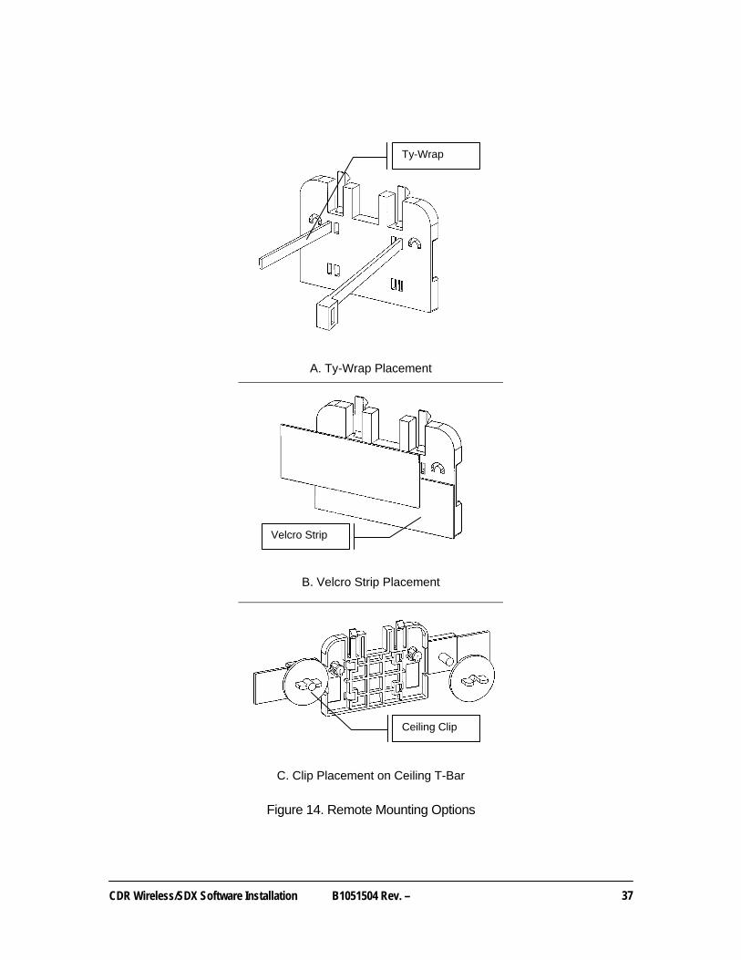
A. Ty-Wrap Placement
B. Velcro Strip Placement
C. Clip Placement on Ceiling T-Bar
Figure 14. Remote Mounting Options
Velcro Strip
Ty-Wrap
Ceiling Clip

38 B1051504 Rev. – CDR Wireless/SDX Software Installation
Index
A Antenna / Receiver
Dental Lamp Pole Mounting, 33 Picture of Base, 34 Picture of Protective Panel, 32 Surface Mounting, 36 Suspended Ceiling Mounting, 36 Symbol on, 30 Wall Mounting, 33
Antenna / Receiver Positioning Picture of, 31
Attaching Antenna / Receiver Mounting Adapter Picture of, 35
B Battery
Removing Pack from Sensor, 17 Securing Pack to Sensor, 20
C CDR Wireless Sensor
Loading Calibration File, 6, 12 Positioning, 19 Preparing, 16 Setup and Turn on, 16 Turning on, 19
CDR Wireless System Important Setup Reminders, 3 Picture of, 1
CDR Wireless System Installation, 4 Overview, 4 Procedures, 5
CDR Wireless System Upgrade Overview, 7 Procedures, 8
CDR2000 Sensor Loading Calibration File, 14
F Final Checks
CDR 2000 Sensor in SDX System, 14 CDR Wireless Sensor in CDR Wireless System
Upgrade, 9 CDR Wireless Sensor in New CDR Wireless
System Installation, 6 CDR Wireless Sensor in SDX System, 12
Firmware Installation for Upgrade Wireless Users, 8
G Getting Started, 1
M Mounting Option
Docked USB Interface and Antenna / Receiver, 30 Undocked USB Interface and Antenna / Receiver,
31 Undocking Units for Remote Positioning, 32
Mounting Options Alternate, 37
O Overview, 1
P Placing Sensor in Sensor Cradle
Picture of, 18 Protective Panel
Antenna / Receiver Picture of, 32 USB Interface Picture of, 32
R Registering Wireless Sensors, 28 RF Environment Test, 25
Picture of, 25 RF Noise
Checking for, 5, 9, 11
S SDX System
Picture of, 2 SDX System Installation, 10
CDR Wireless Sensor Overview, 10 CDR Wireless Sensor Procedures, 11 CDR2000 Sensor Procedures, 13, 14
SDX USB Interface Picture of Base, 34
SDX Utility Introduction, 21 Picture of, 23 Real-Time RF Environment Test, 25 Receiver Upgrade, 24 Register Sensors, 28 Sensor Monitor, 28 Sensor Upgrade, 24 USB Upgrade, 22 Using, 21
Sensor Monitor, 28 Setup
CDR Wireless Sensor, 16 Software
Installation for New Wireless System Customer, 5

CDR Wireless/SDX Software Installation B1051504 Rev. –
39
Installation for SDX System with CDR Wireless Sensors, 11
Installation for SDX System with CDR2000 Sensors, 14
Installation for Upgrade Wireless System Customer, 8
Preparing to Install, 5, 8, 11, 14
T Terms Used in this Document
Explanation of, 3
U USB Interface
Picture of Base, 34 Picture of Protective Panel, 32 Wall or Surface Mounting, 33
USB Interface and Remote Module Positioning, 30
USB Test Pattern Picture of, 23
W Wireless Sensor Registration
Picture of, 29

40 B1051504 Rev. – CDR Wireless/SDX Software Installation
NOTES