CDF Gas Systems Procedures - Fermilab
53
CDF PROC - 311 "CDF Gas Systems Procedures" 3/12/01 2:30 PM __________________________________________________________________ ___ page 1 of 55 CDF Gas Systems Procedures
Transcript of CDF Gas Systems Procedures - Fermilab

CDF PROC - 311 "CDF Gas Systems Procedures" 3/12/01 2:30 PM_____________________________________________________________________
page 1 of 55
CDF Gas Systems Procedures

CDF PROC - 311 "CDF Gas Systems Procedures" 3/12/01 2:30 PM_____________________________________________________________________
page 2 of 55
1.0 Controlled Copies of this procedure.
Two controlled copies of this procedure will exist in the following locations:
1. CDF Gas Tech Bench in the north-east corner of the CDF AssemblyBuilding
2. CDF Department Office

CDF PROC - 311 "CDF Gas Systems Procedures" 3/12/01 2:30 PM_____________________________________________________________________
page 3 of 55
2.0 The Procedure.
To execute a procedure from the checklist, obtain the appropriate section from oneof the tan folders on the CDF Gas Tech Bench. Make sure the date in the header of thechecklist agrees with the date in the header of this page. Place the completed checklist inthe primary mixing logbook, located on the table at the north end of the tech area.
CDF PROC - 311 "CDF Gas Systems Procedures" 3/12/01 2:30 PM_____________________________________________________________________
page 4 of 55
3.0 Checklist
The following checklist is for the operation of the CDF Argon/Ethane Gas MixingSystem. It assumes that all safety systems are in place, including the flammable gas andODH detection systems, and that all pressure and leak tests have been performedsuccessfully.
Table of Checklist Sections
Vent Stack, Vacuum Vent, and Telephone Purge Flow Settings .............................5Vacuum Pump Oil Casing Purge Setting ....................................................................6Mix Shed Vacuum System ROR Measurement.......................................................7General Trailer Connection Notes.................................................................................9Ethane Trailer No. 1 Hook Up.......................................................................................10Ethane Trailer No. 2 Hook Up.......................................................................................13Ethane Trailer No. 3 Hook Up.......................................................................................16Hydrogen Sulfide Vessel Regeneration .....................................................................19Argon Supply Line Evacuation and Fill ........................................................................20Ethane Supply Line Evacuation and Fill.......................................................................22Flow Control Rack and Compressor Suction Evacuation and Fill..............................25Gas Storage Shed Vacuum Manifold ROR................................................................29Gas Shed Piping Evacuation........................................................................................30Storage Tank #1 Evacuation .........................................................................................32Storage Tank #2 Evacuation .........................................................................................34Storage Tank #3 Evacuation .........................................................................................36Storage Tank #4 Evacuation .........................................................................................38Gas Storage Shed System Backfill .............................................................................40Thermal Conductivity Analyzer Set Up.......................................................................43Gas Heater Set Up........................................................................................................44Storage Shed Valve Positioning for Automatic Mixing........................................45Mixing Shed Valve Positioning for Automatic Mixing ................................................47Ethane Filter Change......................................................................................................50Ethane Trailer No. 1 Disconnect ....................................................................................52Ethane Trailer No. 2 Disconnect ....................................................................................53Ethane Trailer No. 3 Disconnect ....................................................................................54
Prior to performing an Argon/Ethane gas mix, the sections listed above must befollowed, in order, from "Vent Stack Purge Flow Setting" through "Mixing ShedValve Positioning for Automatic Mixing". Subsequently, gas mixing is allowedvia the Moore Products programmable logic controller.

CDF PROC - 311 "CDF Gas Systems Procedures" 3/12/01 2:30 PM_____________________________________________________________________
page 5 of 55
Vent Stack, Vacuum Vent, and Telephone Purge Flow Settings
Name:__________________________ Date:__/__/__ Time:____:____
The mix shed vent stack will be purged to keep the stack dry, to keep the oxygencontent low, and to prevent flammable gas from lingering in the stack after a release.
__ Open FI-1701 until 50 SCFH of nitrogen is flowing into the vent stack.
The vent stack purge should be maintained continuously, not only during mixing.
Other purges to maintain continuously include the Vacuum Vent Line and the Telephonepurge. Their flows must be set as indicated below:
__ Open FI-1703 until 60 SCFH of nitrogen is flowing into the vacuum vent line.
__ Open FI-1705 until 5 SCFH of nitrogen is flowing through the telephone purge box.

CDF PROC - 311 "CDF Gas Systems Procedures" 3/12/01 2:30 PM_____________________________________________________________________
page 6 of 55
Vacuum Pump Oil Casing Purge Setting
Name: __________________________ Date:__/__/__ Time:____:____
The mix shed vacuum pump oil casing requires an inert gas purge if the pump is tobe used for flammable gases. MV-1708 must be open for this procedure.__ Open FI-1702 until 10 SCFH of nitrogen is flowing through the pump casing.
The oil casing purge should be maintained continuously, not just during mixing.
CDF PROC - 311 "CDF Gas Systems Procedures" 3/12/01 2:30 PM_____________________________________________________________________
page 7 of 55
Mix Shed Vacuum System ROR Measurement
Name:__________________________ Date:__/__/__ Time:____:____
In later sections, it will be necessary to know the rate-of-rise (hereafter designatedROR) of the vacuum system.
__1. The valves surrounding the vacuum pump should initially be in the followingpositions:
(√) Valve Position__ MV-1104 Closed__ MV-1204 Closed__ MV-1304 Closed__ MV-1405 Closed__ MV-1505 Closed__ PV-1712 (EV-MSVACPISO) Closed__ MV-1713 Open__ MV-1716 Closed__ PV-1717 (EV-MSVACMAN) Closed__ MV-1718 Closed__ MV-1711 Open__ PV-1714 (EV-MSVACMBYP) Open__ MV-1715 Open
__ 2. Verify that PI-1700 and PT-MSVACM1 shows the vacuum manifold pressure tobe 0 psig. Note that PT-MSVACM1 has a range 0 – 50 psia.
__ 3. Close PV-1714 (EV-MSVACMBYP).__ 4. Start the vacuum pump.__ 5. Open PV-1712 (EV-MSVACPISO) in order to pump down the vacuum header
and verify its integrity.__ 6. Wait until PT-MSVACM2 (PE-1700) reads 20 microns or less.
Note: PE-1700 is a Hastings DV-6R vacuum gauge. It has a range from 0-1000microns. A micron is 1/1000th of a millimeter of mercury. PE-1701 is a Hastings DV-4Rvacuum gage with a range of 0-20 millimeters of mercury. PI-1700 is a compoundpressure gauge with a vacuum range of 0-30 inches of mercury. To summarize:
Instrument Range in Micronsabsolute
Range in mm Hgabsolute
Range ininches Hg gauge
PE-1700 0-1,000 0-1PE-1701 0-20,000 0-20PI-1700 760,000-0 760-0 0-30
When making vacuum measurements, use PI-1700 as a first rough measurement,followed by PE-1701 and finally PE-1700. Note that PI-1700 is a gauge instrument (highernumbers mean more vacuum) while PE-1700 and PE-1701 are absolute instruments(higher numbers mean less vacuum). As an example, a reading of 1000 microns on PE-1700 is equivalent to 1 mm Hg on PE-1701 is equivalent to 29.88 in Hg on PI-1700.
__ 7. Close PV-1712 (EV-MSVACPISO) and allow the header to equalize (wait about60 seconds).

CDF PROC - 311 "CDF Gas Systems Procedures" 3/12/01 2:30 PM_____________________________________________________________________
page 8 of 55
PT-MSVACM2 Reading 1: ____ microns.
__ 8. Perform a rate-of-rise measurement using PT-MSVACM2 as follows: Afterwaiting another 60 seconds, take a second reading:
PT-MSVACM2 Reading 2: ____ microns.
Determine the vacuum header ROR by subtracting the first reading from thesecond and dividing by 1 minute.
Vacuum header ROR = (Reading 2 - Reading 1)/1 = ____ microns/min.
The ROR must be less than 1000 microns per hour or 17 microns per minute. Ifthe ROR is greater than 17 microns per minute , a leak exists in the vacuum headerwhich must be corrected before continuing. If the above number is greater than 17microns/min., fix the leak and continue at step 5. If the header ROR is acceptable,shut off the vacuum pump. Write the vacuum header ROR on the bulletin board inthe gas mixing shed and in the log book.
CDF PROC - 311 "CDF Gas Systems Procedures" 3/12/01 2:30 PM_____________________________________________________________________
page 9 of 55
General Trailer Connection Notes
High pressure gas is dangerous to handle if not done properly. The gas exertstremendous forces on its container and any lines open to it. These forces can be amplified ifpressure changes occur rapidly, therefore valves should be cycled slowly and smoothly.All fittings should be rated for the maximum pressure expected, 1875 psig. Beforeconnecting a trailer, inspect the hose for any damage or flaws. If in doubt, tag the hose outof service and notify the gas systems engineer or gas systems manager. Check the VCOO-rings and O-ring surfaces. Repair or replace if necessary. Never leave piping sectionswith ends open; always cap or plug when not in use. This will help keep the piping cleanand protect the O-rings and O-ring surfaces.

CDF PROC - 311 "CDF Gas Systems Procedures" 3/12/01 2:30 PM_____________________________________________________________________
page 10 of 55
Ethane Trailer No. 1 Hook Up
Name:__________________________ Date:__/__/__ Time:____:____
The steps to hook up a trailer include grounding the trailer, evacuating the trailerconnection line and performing a ROR test, backfilling the line with ethane, and drawing asample of ethane if necessary.
__ 1. To ground the trailer, simply connect the grounding cable to the trailer groundinglug. The lug should be clean of paint, dirt, or rust.
__ 2. Before connecting ethane trailer no. 1, the valves associated with ethane trailer no.1 should be in the following positions:
(√) Valve Position__ MV-1100 Closed (and capped)__ MV-1101 Closed__ PV-1100 (EV-MSTR1VLV) Closed__ MV-1102 Open__ MV-1103 Closed__ MV-1104 Closed__ MV-1105 Closed (and capped or connected
to sample bottle)__ MV-1106 Open__ MV-1107 Closed__ MV-1108 Closed (and capped)
__ 3. Check that the vacuum valves for all the other trailers, MV-1505, MV-1405, MV-1204, and MV-1304 are locked closed. PV-1107 (EV-MSTR1SUP) must beclosed as ethane trailer number 1 is not currently supplying the mixing system.
__ 4. The valves at the vacuum pump should initially be in the following positions:
(√) Valve Position__ PV-1712 (EV-MSVACPISO) Closed__ MV-1713 Closed__ MV-1716 Closed__ PV-1717 (EV-MSVACMAN) Closed__ MV-1718 Closed__ MV-1711 Open__ PV-1714 (EV-MSVACMBYP) Open__ MV-1715 Open
__ 5. Open MV-1103 to blow down any connection line residual pressure to the ventstack. Verify atmospheric pressure in ethane trailer 1 supply circuit with PI-1100. Ifan ethane sample must be drawn, continue with step 6, else jump to step 10.
__ 6. Obtain the sample bottle for ethane trailer no. 1, and remove the cap from eachend.
__ 7. Remove the caps from MV-1105 and the sample vent line. Install the samplebottle.
__ 8. Open the sample bottle top valve. Be sure the bottom valve is closed.__ 9. Open MV-1105.

CDF PROC - 311 "CDF Gas Systems Procedures" 3/12/01 2:30 PM_____________________________________________________________________
page 11 of 55
__ 10. Connect the trailer supply flex hose and available SV-1050 assembly to ethanetrailer number 1, LEAVING THE TRAILER VALVE CLOSED.
__ 11. Open PV-1100 (EV-MSTR1VLV) via DMACS.__ 12. Close MV-1103.__ 13. Open MV-1104 followed by MV-1713.__ 14. Verify that PI-1700 and PT-MSVACM1 show the vacuum manifold pressure to
be less than 14.7 psia.__ 15. Close PV-1714 (EV-MSVACMBYP).__ 16. Start the vacuum pump.__ 17. Open PV-1712 (EV-MSVACPISO) to pump down the vacuum header and
connecting line.__ 18. When the connecting line has been pumped to 20 microns or less as read by PT-
MSVACM2 (PE-1700), close PV-1712 (EV-MSVACPISO) and wait 60seconds for the line to equalize.
PT- MSVACM2 Reading 1: ____ microns.
__ 19. Conduct a ROR measurement on the combined vacuum header and connectingline system. Wait one minute and take a second reading using PT-MSVACM2.By subtracting the ROR value for the vacuum header, the ROR for the connectingline is determined. This value has been previously determined in the VacuumSystem ROR Measurement on page 7 and for Run II is approximately 7microns/min. The ROR for the connecting line should be less than 17 microns/min.If the rate of rise is greater, a leak exists which must be corrected before continuing.
PT-MSVACM2 Reading 2: ____ microns.
Combined ROR = (Reading 2 - Reading 1)/1 = ____ microns/min.
Connection Line ROR = Combined ROR – Vac. Header ROR (7 microns/min) = ____ microns/min.
If the above number is greater than 17 microns/min., close PV-1712 (EV-MSVACPISO), fix the leak and return to step 17.
__ 20. Once the ROR is acceptable, isolate the vacuum header by closing MV-1104 andMV-1713.
__ 21. Be sure that the trailer tube manifold valves are open. Then, crack open the trailersupply valve on ethane trailer no. 1 briefly until the connecting line (and samplebottle if in use) are pressurized to 100 psig as read on PI-1100 (first black markingon the gauge).
__ 22. Close the ethane trailer no. 1 supply valve. If the pressure (PI-1100) hasincreased above 100 psig, bleed it back down to 100 psig through MV-1103.
__ 23. Using a hand held flammable gas detector, sniff all connections for flammable gasleaks.
__ 24. If any leaks are present, with the trailer valve closed, depressurize the connectingline by opening MV-1103. After making necessary repairs, return to step 12.
__ 25. If an ethane sample is not required, skip to step 28. To fill the sample cylinder, firstopen MV-1101 at least two turns, then perform steps a. thru d. below three times:
1st 2nd 3rd
__ __ __ a. Pressurize the sample cylinder with MV-1105 open.__ __ __ b. Close MV-1105.
CDF PROC - 311 "CDF Gas Systems Procedures" 3/12/01 2:30 PM_____________________________________________________________________
page 12 of 55
__ __ __ c. Crack open the bottle bottom valve to vent the bottle toabout 5 psig.
__ __ __ d. Close the bottle bottom valve when the bottle pressure isless than 5 psig.
__ 26. Close MV-1101, MV-1105, and the sample bottle top valve.__ 27. Disconnect the sample bottle and replace the caps on the bottle, on MV-1105
and the sample vent line.__ 28. Crack open ethane trailer no. 1 supply valve.__ 29. Record the trailer pressure and temperature:
Trailer No. _____Trailer Pressure: _____ [PSIG]Trailer Temperature: _____ [°F]
__ 30. Turn off the vacuum pump.__ 31. Close ethane trailer no. 1 supply valve.__ 32. Close PV-1100 (EV-MSTR1VLV) via DMACS.__ 33. Replace all valve locks.

CDF PROC - 311 "CDF Gas Systems Procedures" 3/12/01 2:30 PM_____________________________________________________________________
page 13 of 55
Ethane Trailer No. 2 Hook Up
Name:__________________________ Date:__/__/__ Time:____:____
The steps to hook up a trailer include grounding the trailer, evacuating the trailerconnection line and performing a ROR test, backfilling the line with ethane, and drawing asample of ethane if necessary.
__ 1. To ground the trailer, simply connect the grounding cable to the trailer groundinglug. The lug should be clean of paint, dirt, or rust.
__ 2. Before connecting ethane trailer no. 2, the valves associated with ethane trailer no.2 should be in the following positions:
(√) Valve Position__ MV-1200 Closed (and capped)__ MV-1201 Closed__ PV-1200 (EV-MSTR2VLV) Closed__ MV-1202 Open__ MV-1203 Closed__ MV-1204 Closed__ MV-1205 Closed (and capped or connected
to sample bottle)__ MV-1206 Open__ MV-1207 Closed__ MV-1208 Closed (and capped)
__ 3. Check that the vacuum valves for all the other trailers, MV-1505, MV-1405, MV-1104, and MV-1304 are locked closed. PV-1207 (EV-MSTR2SUP) must beclosed as ethane trailer number 2 is not currently supplying the mixing system.
__ 4. The valves at the vacuum pump should initially be in the following positions:
(√) Valve Position__ PV-1712 (EV-MSVACPISO) Closed__ MV-1713 Closed__ MV-1716 Closed__ PV-1717 (EV-MSVACMAN) Closed__ MV-1718 Closed__ MV-1711 Open__ PV-1714 (EV-MSVACMBYP) Open__ MV-1715 Open
__ 5. Open MV-1203 to blow down any connection line residual pressure to the ventstack. Verify atmospheric pressure in ethane trailer 2 supply circuit with PI-1200. Ifan ethane sample must be drawn, continue with step 6, else jump to step 10.
__ 6. Obtain the sample bottle for ethane trailer no. 2, and remove the cap from eachend.
__ 7. Remove the caps from MV-1205 and the sample vent line. Install the samplebottle.
__ 8. Open the sample bottle top valve. Be sure the bottom valve is closed.__ 9. Open MV-1205.
CDF PROC - 311 "CDF Gas Systems Procedures" 3/12/01 2:30 PM_____________________________________________________________________
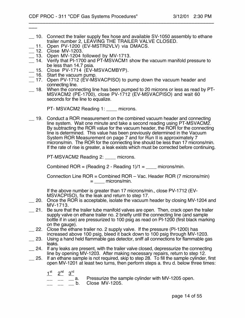
page 14 of 55
__ 10. Connect the trailer supply flex hose and available SV-1050 assembly to ethanetrailer number 2, LEAVING THE TRAILER VALVE CLOSED.
__ 11. Open PV-1200 (EV-MSTR2VLV) via DMACS.__ 12. Close MV-1203.__ 13. Open MV-1204 followed by MV-1713.__ 14. Verify that PI-1700 and PT-MSVACM1 show the vacuum manifold pressure to
be less than 14.7 psia.__ 15. Close PV-1714 (EV-MSVACMBYP).__ 16. Start the vacuum pump.__ 17. Open PV-1712 (EV-MSVACPISO) to pump down the vacuum header and
connecting line.__ 18. When the connecting line has been pumped to 20 microns or less as read by PT-
MSVACM2 (PE-1700), close PV-1712 (EV-MSVACPISO) and wait 60seconds for the line to equalize.
PT- MSVACM2 Reading 1: ____ microns.
__ 19. Conduct a ROR measurement on the combined vacuum header and connectingline system. Wait one minute and take a second reading using PT-MSVACM2.By subtracting the ROR value for the vacuum header, the ROR for the connectingline is determined. This value has been previously determined in the VacuumSystem ROR Measurement on page 7 and for Run II is approximately 7microns/min. The ROR for the connecting line should be less than 17 microns/min.If the rate of rise is greater, a leak exists which must be corrected before continuing.
PT-MSVACM2 Reading 2: ____ microns.
Combined ROR = (Reading 2 - Reading 1)/1 = ____ microns/min.
Connection Line ROR = Combined ROR – Vac. Header ROR (7 microns/min) = ____ microns/min.
If the above number is greater than 17 microns/min., close PV-1712 (EV-MSVACPISO), fix the leak and return to step 17.
__ 20. Once the ROR is acceptable, isolate the vacuum header by closing MV-1204 andMV-1713.
__ 21. Be sure that the trailer tube manifold valves are open. Then, crack open the trailersupply valve on ethane trailer no. 2 briefly until the connecting line (and samplebottle if in use) are pressurized to 100 psig as read on PI-1200 (first black markingon the gauge).
__ 22. Close the ethane trailer no. 2 supply valve. If the pressure (PI-1200) hasincreased above 100 psig, bleed it back down to 100 psig through MV-1203.
__ 23. Using a hand held flammable gas detector, sniff all connections for flammable gasleaks.
__ 24. If any leaks are present, with the trailer valve closed, depressurize the connectingline by opening MV-1203. After making necessary repairs, return to step 12.
__ 25. If an ethane sample is not required, skip to step 28. To fill the sample cylinder, firstopen MV-1201 at least two turns, then perform steps a. thru d. below three times:
1st 2nd 3rd
__ __ __ a. Pressurize the sample cylinder with MV-1205 open.__ __ __ b. Close MV-1205.

CDF PROC - 311 "CDF Gas Systems Procedures" 3/12/01 2:30 PM_____________________________________________________________________
page 15 of 55
__ __ __ c. Crack open the bottle bottom valve to vent the bottle toabout 5 psig.
__ __ __ d. Close the bottle bottom valve when the bottle pressure isless than 5 psig.
__ 26. Close MV-1201, MV-1205, and the sample bottle top valve.__ 27. Disconnect the sample bottle and replace the caps on the bottle, on MV-1205
and the sample vent line.__ 28. Crack open ethane trailer no. 2 supply valve.__ 29. Record the trailer pressure and temperature:
Trailer No. _____Trailer Pressure: _____ [PSIG]Trailer Temperature: _____ [°F]
__ 30. Turn off the vacuum pump.__ 31. Close ethane trailer no. 2 supply valve.__ 32. Close PV-1200 (EV-MSTR2VLV) via DMACS.__ 33. Replace all valve locks.
CDF PROC - 311 "CDF Gas Systems Procedures" 3/12/01 2:30 PM_____________________________________________________________________
page 16 of 55
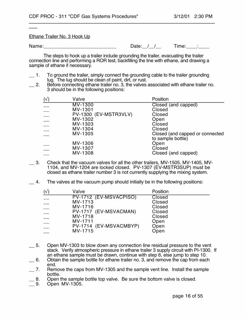
Ethane Trailer No. 3 Hook Up
Name:__________________________ Date:__/__/__ Time:____:____
The steps to hook up a trailer include grounding the trailer, evacuating the trailerconnection line and performing a ROR test, backfilling the line with ethane, and drawing asample of ethane if necessary.
__ 1. To ground the trailer, simply connect the grounding cable to the trailer groundinglug. The lug should be clean of paint, dirt, or rust.
__ 2. Before connecting ethane trailer no. 3, the valves associated with ethane trailer no.3 should be in the following positions:
(√) Valve Position__ MV-1300 Closed (and capped)__ MV-1301 Closed__ PV-1300 (EV-MSTR3VLV) Closed__ MV-1302 Open__ MV-1303 Closed__ MV-1304 Closed__ MV-1305 Closed (and capped or connected
to sample bottle)__ MV-1306 Open__ MV-1307 Closed__ MV-1308 Closed (and capped)
__ 3. Check that the vacuum valves for all the other trailers, MV-1505, MV-1405, MV-1104, and MV-1204 are locked closed. PV-1307 (EV-MSTR3SUP) must beclosed as ethane trailer number 3 is not currently supplying the mixing system.
__ 4. The valves at the vacuum pump should initially be in the following positions:
(√) Valve Position__ PV-1712 (EV-MSVACPISO) Closed__ MV-1713 Closed__ MV-1716 Closed__ PV-1717 (EV-MSVACMAN) Closed__ MV-1718 Closed__ MV-1711 Open__ PV-1714 (EV-MSVACMBYP) Open__ MV-1715 Open
__ 5. Open MV-1303 to blow down any connection line residual pressure to the ventstack. Verify atmospheric pressure in ethane trailer 3 supply circuit with PI-1300. Ifan ethane sample must be drawn, continue with step 6, else jump to step 10.
__ 6. Obtain the sample bottle for ethane trailer no. 3, and remove the cap from eachend.
__ 7. Remove the caps from MV-1305 and the sample vent line. Install the samplebottle.
__ 8. Open the sample bottle top valve. Be sure the bottom valve is closed.__ 9. Open MV-1305.

CDF PROC - 311 "CDF Gas Systems Procedures" 3/12/01 2:30 PM_____________________________________________________________________
page 17 of 55
__ 10. Connect the trailer supply flex hose and available SV-1050 assembly to ethanetrailer number 3, LEAVING THE TRAILER VALVE CLOSED.
__ 11. Open PV-1300 (EV-MSTR3VLV) via DMACS.__ 12. Close MV-1303.__ 13. Open MV-1304 followed by MV-1713.__ 14. Verify that PI-1700 and PT-MSVACM1 show the vacuum manifold pressure to
be less than 14.7 psia.__ 15. Close PV-1714 (EV-MSVACMBYP).__ 16. Start the vacuum pump.__ 17. Open PV-1712 (EV-MSVACPISO) to pump down the vacuum header and
connecting line.__ 18. When the connecting line has been pumped to 20 microns or less as read by PT-
MSVACM2 (PE-1700), close PV-1712 (EV-MSVACPISO) and wait 60seconds for the line to equalize.
PT- MSVACM2 Reading 1: ____ microns.
__ 19. Conduct a ROR measurement on the combined vacuum header and connectingline system. Wait one minute and take a second reading using PT-MSVACM2.By subtracting the ROR value for the vacuum header, the ROR for the connectingline is determined. This value has been previously determined in the VacuumSystem ROR Measurement on page 7 and for Run II is approximately 7microns/min. The ROR for the connecting line should be less than 17 microns/min.If the rate of rise is greater, a leak exists which must be corrected before continuing.
PT-MSVACM2 Reading 2: ____ microns.
Combined ROR = (Reading 2 - Reading 1)/1 = ____ microns/min.
Connection Line ROR = Combined ROR - Vac. Header ROR (7 microns/min) = ____ microns/min.
If the above number is greater than 17 microns/min., close PV-1712 (EV-MSVACPISO), fix the leak and return to step 17.
__ 20. Once the ROR is acceptable, isolate the vacuum header by closing MV-1304 andMV-1713.
__ 21. Be sure that the trailer tube manifold valves are open. Then, crack open the trailersupply valve on ethane trailer no. 3 briefly until the connecting line (and samplebottle if in use) are pressurized to 100 psig as read on PI-1300 (first black markingon the gauge).
__ 22. Close the ethane trailer no. 3 supply valve. If the pressure (PI-1300) hasincreased above 100 psig, bleed it back down to 100 psig through MV-1303.
__ 23. Using a hand held flammable gas detector, sniff all connections for flammable gasleaks.
__ 24. If any leaks are present, with the trailer valve closed, depressurize the connectingline by opening MV-1303. After making necessary repairs, return to step 12.
__ 25. If an ethane sample is not required, skip to step 28. To fill the sample cylinder, firstopen MV-1301 at least two turns, then perform steps a. thru d. below three times:
1st 2nd 3rd
__ __ __ a. Pressurize the sample cylinder with MV-1305 open.__ __ __ b. Close MV-1305.

CDF PROC - 311 "CDF Gas Systems Procedures" 3/12/01 2:30 PM_____________________________________________________________________
page 18 of 55
__ __ __ c. Crack open the bottle bottom valve to vent the bottle toabout 5 psig.
__ __ __ d. Close the bottle bottom valve when the bottle pressure isless than 5 psig.
__ 26. Close MV-1301, MV-1305, and the sample bottle top valve.__ 27. Disconnect the sample bottle and replace the caps on the bottle, on MV-1305
and the sample vent line.__ 28. Crack open ethane trailer no. 3 supply valve.__ 29. Record the trailer pressure and temperature:
Trailer No. _____Trailer Pressure: _____ [PSIG]Trailer Temperature: _____ [°F]
__ 30. Turn off the vacuum pump.__ 31. Close ethane trailer no. 3 supply valve.__ 32. Close PV-1300 (EV-MSTR3VLV) via DMACS.__ 33. Replace all valve locks.
CDF PROC - 311 "CDF Gas Systems Procedures" 3/12/01 2:30 PM_____________________________________________________________________
page 19 of 55
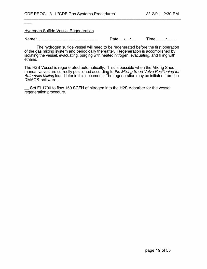
Hydrogen Sulfide Vessel Regeneration
Name:__________________________ Date:__/__/__ Time:____:____
The hydrogen sulfide vessel will need to be regenerated before the first operationof the gas mixing system and periodically thereafter. Regeneration is accomplished byisolating the vessel, evacuating, purging with heated nitrogen, evacuating, and filling withethane.
The H2S Vessel is regenerated automatically. This is possible when the Mixing Shedmanual valves are correctly positioned according to the Mixing Shed Valve Positioning forAutomatic Mixing found later in this document. The regeneration may be initiated from theDMACS software.
__ Set FI-1700 to flow 150 SCFH of nitrogen into the H2S Adsorber for the vesselregeneration procedure.
CDF PROC - 311 "CDF Gas Systems Procedures" 3/12/01 2:30 PM_____________________________________________________________________
page 20 of 55
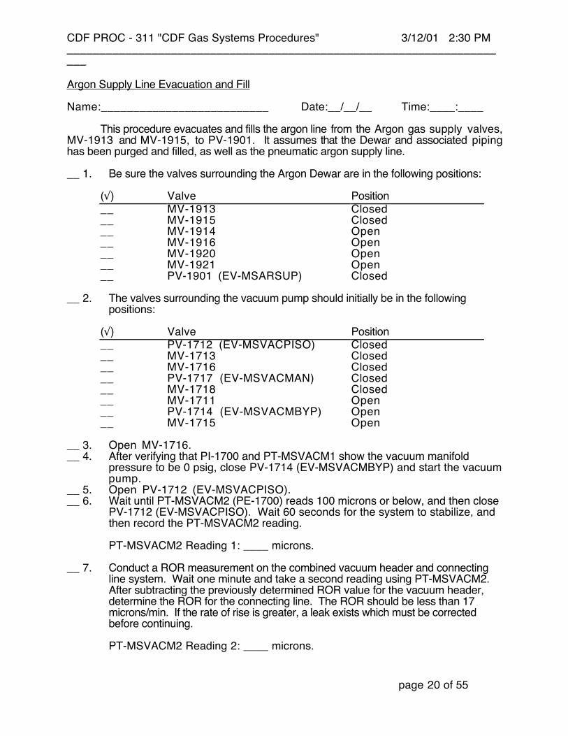
Argon Supply Line Evacuation and Fill
Name:__________________________ Date:__/__/__ Time:____:____
This procedure evacuates and fills the argon line from the Argon gas supply valves,MV-1913 and MV-1915, to PV-1901. It assumes that the Dewar and associated pipinghas been purged and filled, as well as the pneumatic argon supply line.
__ 1. Be sure the valves surrounding the Argon Dewar are in the following positions:
(√) Valve Position__ MV-1913 Closed__ MV-1915 Closed__ MV-1914 Open__ MV-1916 Open__ MV-1920 Open__ MV-1921 Open__ PV-1901 (EV-MSARSUP) Closed
__ 2. The valves surrounding the vacuum pump should initially be in the followingpositions:
(√) Valve Position__ PV-1712 (EV-MSVACPISO) Closed__ MV-1713 Closed__ MV-1716 Closed__ PV-1717 (EV-MSVACMAN) Closed__ MV-1718 Closed__ MV-1711 Open__ PV-1714 (EV-MSVACMBYP) Open__ MV-1715 Open
__ 3. Open MV-1716.__ 4. After verifying that PI-1700 and PT-MSVACM1 show the vacuum manifold
pressure to be 0 psig, close PV-1714 (EV-MSVACMBYP) and start the vacuumpump.
__ 5. Open PV-1712 (EV-MSVACPISO).__ 6. Wait until PT-MSVACM2 (PE-1700) reads 100 microns or below, and then close
PV-1712 (EV-MSVACPISO). Wait 60 seconds for the system to stabilize, andthen record the PT-MSVACM2 reading.
PT-MSVACM2 Reading 1: ____ microns.
__ 7. Conduct a ROR measurement on the combined vacuum header and connectingline system. Wait one minute and take a second reading using PT-MSVACM2.After subtracting the previously determined ROR value for the vacuum header,determine the ROR for the connecting line. The ROR should be less than 17microns/min. If the rate of rise is greater, a leak exists which must be correctedbefore continuing.
PT-MSVACM2 Reading 2: ____ microns.
CDF PROC - 311 "CDF Gas Systems Procedures" 3/12/01 2:30 PM_____________________________________________________________________
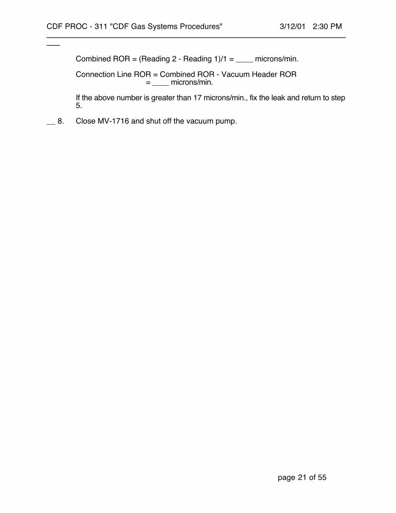
page 21 of 55
Combined ROR = (Reading 2 - Reading 1)/1 = ____ microns/min.
Connection Line ROR = Combined ROR - Vacuum Header ROR = ____ microns/min.
If the above number is greater than 17 microns/min., fix the leak and return to step5.
__ 8. Close MV-1716 and shut off the vacuum pump.
CDF PROC - 311 "CDF Gas Systems Procedures" 3/12/01 2:30 PM_____________________________________________________________________
page 22 of 55
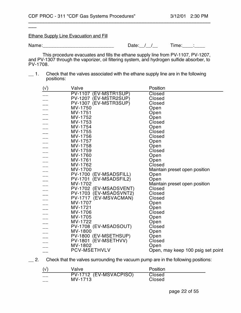
Ethane Supply Line Evacuation and Fill
Name:__________________________ Date:__/__/__ Time:____:____
This procedure evacuates and fills the ethane supply line from PV-1107, PV-1207,and PV-1307 through the vaporizer, oil filtering system, and hydrogen sulfide absorber, toPV-1708.
__ 1. Check that the valves associated with the ethane supply line are in the followingpositions:
(√) Valve Position__ PV-1107 (EV-MSTR1SUP) Closed__ PV-1207 (EV-MSTR2SUP) Closed__ PV-1307 (EV-MSTR3SUP) Closed__ MV-1750 Open__ MV-1751 Open__ MV-1752 Open__ MV-1753 Closed__ MV-1754 Open__ MV-1755 Closed__ MV-1756 Closed__ MV-1757 Open__ MV-1758 Open__ MV-1759 Closed__ MV-1760 Open__ MV-1761 Open__ MV-1762 Closed__ MV-1700 Maintain preset open position__ PV-1700 (EV-MSADSFILL) Open__ PV-1701 (EV-MSADSFIL2) Open__ MV-1702 Maintain preset open position__ PV-1702 (EV-MSADSVENT) Closed__ PV-1703 (EV-MSADSVNT2) Closed__ PV-1717 (EV-MSVACMAN) Closed__ MV-1707 Open__ MV-1721 Open__ MV-1706 Closed__ MV-1705 Open__ MV-1722 Open__ PV-1708 (EV-MSADSOUT) Closed__ MV-1800 Open__ PV-1800 (EV-MSETHSUP) Open__ PV-1801 (EV-MSETHVV) Closed__ MV-1802 Open__ PCV-MSETHVLV Open, may keep 100 psig set point
__ 2. Check that the valves surrounding the vacuum pump are in the following positions:
(√) Valve Position__ PV-1712 (EV-MSVACPISO) Closed__ MV-1713 Closed

CDF PROC - 311 "CDF Gas Systems Procedures" 3/12/01 2:30 PM_____________________________________________________________________
page 23 of 55
__ MV-1716 Closed__ PV-1717 (EV-MSVACMAN) Closed__ MV-1718 Closed__ MV-1711 Open__ PV-1714 (EV-MSVACMBYP) Open__ MV-1715 Open
__ 3. Open PV-1717 (EV-MSVACMAN).__ 4. After verifying that PI-1700 and PT-MSVACM1 show the vacuum manifold
pressure to be 0 psig, close PV-1714 (EV-MSVACMBYP).__ 5. Start the vacuum pump.__ 6. Open PV-1712 (EV-MSVACPISO) slowly.__ 7. Wait until PT-MSVACM2 (PE-1700) reads 100 microns or below, and then close
PV-1712 (EV-MSVACPISO). Wait 60 seconds for the system to stabilize, andthen take a reading.
PT-MSVACM2 Reading 1: ____ microns.
__ 8. Conduct a ROR measurement on the combined vacuum header and connectingline system. Wait one minute and take a second reading using PT-MSVACM2.After subtracting the previously determined ROR value for the vacuum header,determine the ROR for the connecting line.
PT-MSVACM2 Reading 2: ____ microns.
Combined ROR = (Reading 2 - Reading 1)/1 = ____ microns/min.
Connection Line ROR = Combined ROR - Vacuum Header ROR = ____ microns/min.
If the above number is greater than 17 microns/min., fix the leak and continue atstep 6. If the number is 17 micron/min. or less, continue below.
__ 9. Once the ROR is acceptable, isolate the vacuum header by closing PV-1717 (EV-MSVACMAN).
__ 10. Shut off the vacuum pump.__ 11. Close MV-1752, MV-1707, and PV-1701 (EV-MSADSFIL2).__ 12. Be sure the PCV-MSETHVLV set point is 100 psig. If ethane trailer 1 is currently
supplying ethane for the mixing system, close PV-1100 (EV-MSTR1VLV) andthen open PV-1107 (EV-MSTR1SUP) to reintroduce ethane into the ethanesupply line. If trailer 2 is the supply trailer, close PV-1200 (EV-MSTR2VLV) andopen PV-1207 (EV-MSTR2SUP); and if trailer 3 is the supply trailer, close PV-1300 (EV-MSTR3VLV) and open PV-1307 (EV-MSTR3SUP). After the linepressure is stable as read on PT-MSADS and PI-1701, reopen the currentlyapproved supply trailer valve PV-1100 (EV-MSTR1VLV), or PV-1200 (EV-MSTR2VLV), or PV-1300 (EV-MSTR3VLV).
__ 13. Once PT-MSADS and PI-1701 indicate 100 psig, open PV-1701 (EV-MSADSFIL2) and close PV-1700 (EV-MSADSFILL). Open MV-1706.
The system is now evacuated and charged with ethane up to PV-1708. Beforemixing, all Mix Shed valve positions will be confirmed using Mixing Shed ValvePositioning for Automatic Mixing found later in this procedure.

CDF PROC - 311 "CDF Gas Systems Procedures" 3/12/01 2:30 PM_____________________________________________________________________
page 24 of 55
Flow Control Rack and Compressor Suction Evacuation and Fill
Name:__________________________ Date:__/__/__ Time:____:____
This procedure evacuates and fills the ethane line from PV-1708 through the ethaneflow control station, the argon line from PV-1901 through the argon flow control station, andthe mix line from the flow control stations to the compressors behind CDF.
__ 1. Configure the valves in and around the mix shed and flow control stations in thefollowing positions:
(√) Valve Position__ MV-1406 Closed__ MV-1506 Closed__ PV-1708 (EV-MSADSOUT) Closed__ PV-1709 (EV-MSAEDEL) Open__ PV-1710 (EV-MSAEMIXVT) Closed__ PV-1719 (EV-MSAE2GM) Open__ PV-1721 (EV-MSGMZERO) Closed__ PV-1722 (EV-MSGMBYP) Closed__ MV-1724 Closed__ PV-1725 (EV-MSAFCOUT1) Open__ PV-1727 (EV-MSAFCOUT2) Open__ PV-1728 (EV-MSAFCIN1) Open__ PV-1730 (EV-MSAFCIN2) Open__ MV-1730 Closed__ MV-1731 Closed__ MV-1732 Closed__ PV-1733 (EV-MSEFCOUT1) Open__ MV-1734 Closed__ PV-1736 (EV-MSEFCOUT2) Open__ PV-1737 (EV-MSEFCIN1) Open__ PV-1739 (EV-MSEFCIN2) Open__ MV-1740 Open__ MV-1741 Open__ PV-1901 (EV-MSARSUP) Closed__ MV-1930 Closed
__ 2. Configure the valves surrounding the vacuum pump in the following positions:
(√) Valve Position__ PV-1712 (EV-MSVACPISO) Closed__ MV-1713 Closed__ MV-1716 Closed__ PV-1717 (EV-MSVACMAN) Closed__ MV-1718 Closed__ MV-1711 Open__ PV-1714 (EV-MSVACMBYP) Open__ MV-1715 Open

CDF PROC - 311 "CDF Gas Systems Procedures" 3/12/01 2:30 PM_____________________________________________________________________
page 25 of 55
__ 3. Open the four flow controllers (FCV-MSAFC1, FCV-MSAFC2, FCV-MSEFC1,and FCV-MSEFC2) by putting all four command control switches (on the HastingsFlow Power Supply in the Mix Shed Rack) in the "open" position.
__ 4. Open MV-1718 followed by MV-1724, MV-1731, MV-1732, and MV-1734.__ 5. After verifying that PT-MSVACM1 and PI-1700 show the vacuum manifold
pressure to be 0 psig, close PV-1714 (EV-MSVACMBYP).__ 6. Start the vacuum pump.__ 7. Open PV-1712 (EV-MSVACPISO).__ 8. Proceed to the gas storage shed and ensure that the following valves associated
with the compressors are in the following positions:
(√) Valve Position__ MV-2002 Closed__ MV-2003 Open__ MV-2004 Closed__ PV-2005 (EV-GSCMPIN) Closed__ MV-2016 Closed__ MV-2104 Closed__ MV-2204 Closed__ MV-2208 Closed__ MV-2304 Closed__ MV-2503 Closed__ MV-2603 Closed__ MV-2506 Closed__ MV-2606 Closed
__ 9. Connect the portable vacuum pump to MV-2002 via a flex hose.__ 10. Connect a Hastings thermocouple vacuum gauge to the portable vacuum pump.__ 11. Start the portable vacuum pump.__ 12. Open MV-2002 and then open MV-2004 to begin pumping down the
compressor suction line.__ 13. Wait until the vacuum gauge reads 100 microns or less, then close MV-2002 and
return to the gas mixing shed.__ 14. Wait until PT-MSVACM2 reads 100 microns or below.__ 15. Close PV-1712 (EV-MSVACPISO) and wait 60 seconds for the system to
equalize.
PT-MSVACM2 Reading 1: ____ microns.
__ 16. Conduct a ROR measurement on the combined vacuum header and flow controlstations. Wait five minutes and take a reading using PT-MSVACM2.
PT-MSVACM2 Reading 2: ____ microns.
Combined ROR = (Reading 2 - Reading 1)/5 = ____ microns/min.
After subtracting the previously determined ROR value for the vacuum header,determine the ROR for the flow control stations.
Flow Control Rack ROR = Combined ROR - Vacuum Header ROR = ____ microns/min.
CDF PROC - 311 "CDF Gas Systems Procedures" 3/12/01 2:30 PM_____________________________________________________________________
page 26 of 55
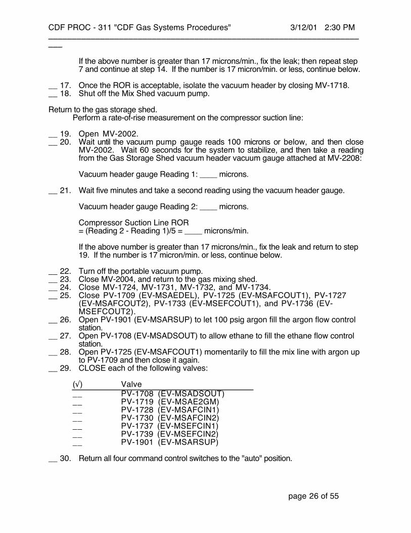
If the above number is greater than 17 microns/min., fix the leak; then repeat step7 and continue at step 14. If the number is 17 micron/min. or less, continue below.
__ 17. Once the ROR is acceptable, isolate the vacuum header by closing MV-1718.__ 18. Shut off the Mix Shed vacuum pump.
Return to the gas storage shed.Perform a rate-of-rise measurement on the compressor suction line:
__ 19. Open MV-2002.__ 20. Wait until the vacuum pump gauge reads 100 microns or below, and then close
MV-2002. Wait 60 seconds for the system to stabilize, and then take a readingfrom the Gas Storage Shed vacuum header vacuum gauge attached at MV-2208:
Vacuum header gauge Reading 1: ____ microns.
__ 21. Wait five minutes and take a second reading using the vacuum header gauge.
Vacuum header gauge Reading 2: ____ microns.
Compressor Suction Line ROR= (Reading 2 - Reading 1)/5 = ____ microns/min.
If the above number is greater than 17 microns/min., fix the leak and return to step19. If the number is 17 micron/min. or less, continue below.
__ 22. Turn off the portable vacuum pump.__ 23. Close MV-2004, and return to the gas mixing shed.__ 24. Close MV-1724, MV-1731, MV-1732, and MV-1734.__ 25. Close PV-1709 (EV-MSAEDEL), PV-1725 (EV-MSAFCOUT1), PV-1727
(EV-MSAFCOUT2), PV-1733 (EV-MSEFCOUT1), and PV-1736 (EV-MSEFCOUT2).
__ 26. Open PV-1901 (EV-MSARSUP) to let 100 psig argon fill the argon flow controlstation.
__ 27. Open PV-1708 (EV-MSADSOUT) to allow ethane to fill the ethane flow controlstation.
__ 28. Open PV-1725 (EV-MSAFCOUT1) momentarily to fill the mix line with argon upto PV-1709 and then close it again.
__ 29. CLOSE each of the following valves:
(√) Valve__ PV-1708 (EV-MSADSOUT)__ PV-1719 (EV-MSAE2GM)__ PV-1728 (EV-MSAFCIN1)__ PV-1730 (EV-MSAFCIN2)__ PV-1737 (EV-MSEFCIN1)__ PV-1739 (EV-MSEFCIN2)__ PV-1901 (EV-MSARSUP)
__ 30. Return all four command control switches to the "auto" position.
CDF PROC - 311 "CDF Gas Systems Procedures" 3/12/01 2:30 PM_____________________________________________________________________
page 27 of 55
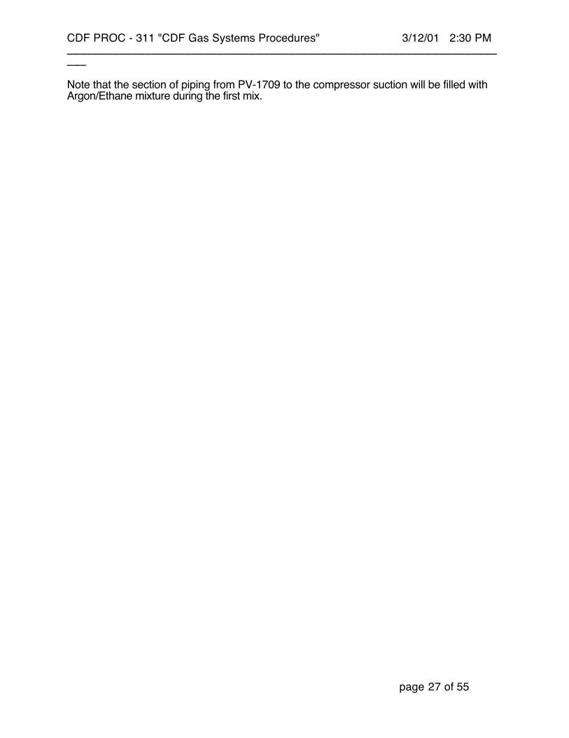
Note that the section of piping from PV-1709 to the compressor suction will be filled withArgon/Ethane mixture during the first mix.
CDF PROC - 311 "CDF Gas Systems Procedures" 3/12/01 2:30 PM_____________________________________________________________________
page 28 of 55
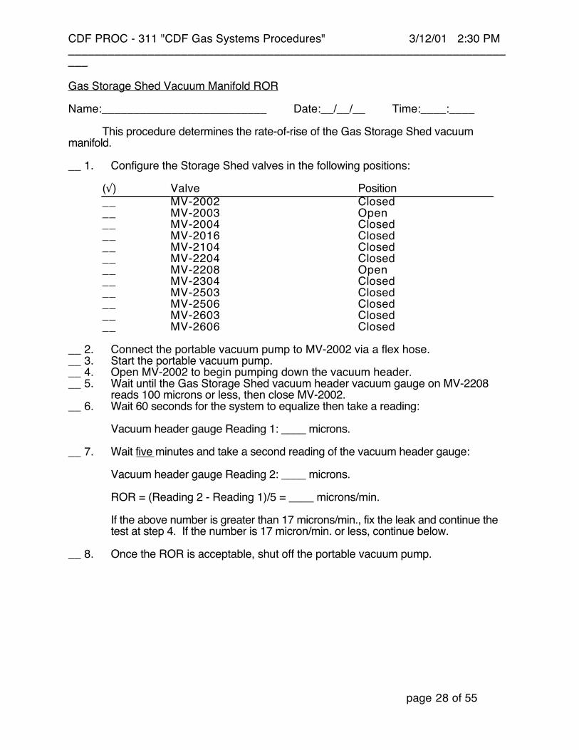
Gas Storage Shed Vacuum Manifold ROR
Name:__________________________ Date:__/__/__ Time:____:____
This procedure determines the rate-of-rise of the Gas Storage Shed vacuummanifold.
__ 1. Configure the Storage Shed valves in the following positions:
(√) Valve Position__ MV-2002 Closed__ MV-2003 Open__ MV-2004 Closed__ MV-2016 Closed__ MV-2104 Closed__ MV-2204 Closed__ MV-2208 Open__ MV-2304 Closed__ MV-2503 Closed__ MV-2506 Closed__ MV-2603 Closed__ MV-2606 Closed
__ 2. Connect the portable vacuum pump to MV-2002 via a flex hose.__ 3. Start the portable vacuum pump.__ 4. Open MV-2002 to begin pumping down the vacuum header.__ 5. Wait until the Gas Storage Shed vacuum header vacuum gauge on MV-2208
reads 100 microns or less, then close MV-2002.__ 6. Wait 60 seconds for the system to equalize then take a reading:
Vacuum header gauge Reading 1: ____ microns.
__ 7. Wait five minutes and take a second reading of the vacuum header gauge:
Vacuum header gauge Reading 2: ____ microns.
ROR = (Reading 2 - Reading 1)/5 = ____ microns/min.
If the above number is greater than 17 microns/min., fix the leak and continue thetest at step 4. If the number is 17 micron/min. or less, continue below.
__ 8. Once the ROR is acceptable, shut off the portable vacuum pump.
CDF PROC - 311 "CDF Gas Systems Procedures" 3/12/01 2:30 PM_____________________________________________________________________
page 29 of 55
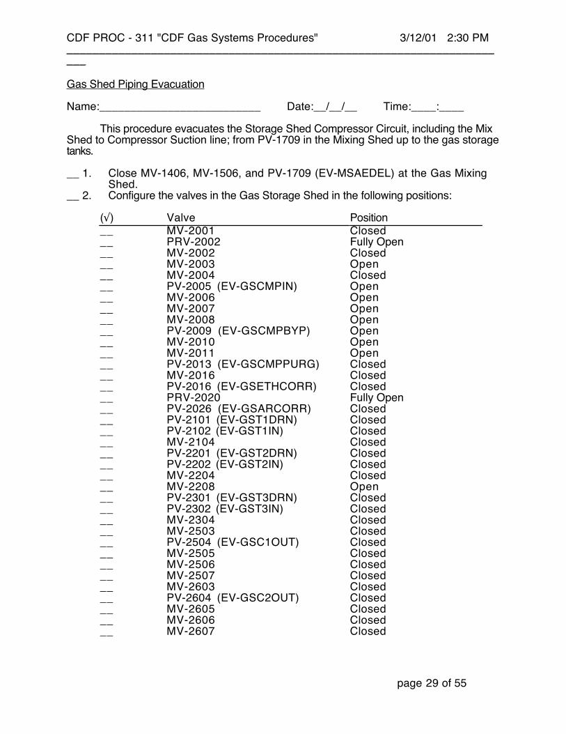
Gas Shed Piping Evacuation
Name:__________________________ Date:__/__/__ Time:____:____
This procedure evacuates the Storage Shed Compressor Circuit, including the MixShed to Compressor Suction line; from PV-1709 in the Mixing Shed up to the gas storagetanks.
__ 1. Close MV-1406, MV-1506, and PV-1709 (EV-MSAEDEL) at the Gas MixingShed.
__ 2. Configure the valves in the Gas Storage Shed in the following positions:
(√) Valve Position__ MV-2001 Closed__ PRV-2002 Fully Open__ MV-2002 Closed__ MV-2003 Open__ MV-2004 Closed__ PV-2005 (EV-GSCMPIN) Open__ MV-2006 Open__ MV-2007 Open__ MV-2008 Open__ PV-2009 (EV-GSCMPBYP) Open__ MV-2010 Open__ MV-2011 Open__ PV-2013 (EV-GSCMPPURG) Closed__ MV-2016 Closed__ PV-2016 (EV-GSETHCORR) Closed__ PRV-2020 Fully Open__ PV-2026 (EV-GSARCORR) Closed__ PV-2101 (EV-GST1DRN) Closed__ PV-2102 (EV-GST1IN) Closed__ MV-2104 Closed__ PV-2201 (EV-GST2DRN) Closed__ PV-2202 (EV-GST2IN) Closed__ MV-2204 Closed__ MV-2208 Open__ PV-2301 (EV-GST3DRN) Closed__ PV-2302 (EV-GST3IN) Closed__ MV-2304 Closed__ MV-2503 Closed__ PV-2504 (EV-GSC1OUT) Closed__ MV-2505 Closed__ MV-2506 Closed__ MV-2507 Closed__ MV-2603 Closed__ PV-2604 (EV-GSC2OUT) Closed__ MV-2605 Closed__ MV-2606 Closed__ MV-2607 Closed

CDF PROC - 311 "CDF Gas Systems Procedures" 3/12/01 2:30 PM_____________________________________________________________________
page 30 of 55
__ 3. Connect the portable vacuum pump to MV-2002 via a flex hose.__ 4. Start the vacuum pump.__ 5. Open MV-2002 and then MV-2004 to begin pumping down the compressor
circuit.__ 6. Wait for the Gas Storage Shed vacuum header vacuum gauge on MV-2208 to
read 100 microns or less, then close MV-2002.
Perform a ROR measurement on the combined vacuum header and compressor circuit:__ 7. Wait 60 seconds for the system to equalize, then take a reading:
Vacuum header gauge Reading 1: ____ microns.
__ 8. Wait five minutes and take a second reading:
Vacuum header gauge Reading 2: ____ microns.
Combined ROR = (Reading 2 - Reading 1)/5 = ____ microns/min.
Subtract the previously determined ROR value for the Storage Shed vacuumheader to determine the ROR for the compressor circuit.
Compressor Circuit ROR = Combined ROR - Vacuum Header ROR = ____ microns/min.
If the above ROR is greater than 17 microns/min., fix the leak and continue the testat step 4. If the ROR is 17 micron/min. or less, continue below.
__ 9. Once the ROR is acceptable close MV-2004.__ 10. Shut off the portable vacuum pump.

CDF PROC - 311 "CDF Gas Systems Procedures" 3/12/01 2:30 PM_____________________________________________________________________
page 31 of 55
Storage Tank #1 Evacuation
Name:__________________________ Date:__/__/__ Time:____:____
This procedure evacuates the #1 Gas Shed storage tank.
__ 1. Configure the Gas Storage Shed valves in the following positions:
(√) Valve Position__ MV-2002 Closed__ MV-2003 Open__ MV-2004 Closed__ MV-2016 Closed__ PV-2100 (EV-GST2OUT) Closed__ PV-2101 (EV-GST2DRN) Closed__ MV-2102 Open__ PV-2102 (EV-GST2IN) Closed__ MV-2103 Closed__ MV-2104 Closed__ MV-2105 Closed__ MV-2106 Open__ MV-2107 Closed__ MV-2204 Closed__ MV-2208 Closed__ MV-2304 Closed__ MV-2503 Closed__ MV-2506 Closed__ MV-2603 Closed__ MV-2606 Closed
__ 2. Connect the portable vacuum pump to MV-2002 via a flex hose.__ 3. Start the vacuum pump.__ 4. Open MV-2002 and then MV-2104 to begin pumping down storage tank #1.__ 5. Wait for PE-2100 to read 100 microns or less, then close MV-2002.
Perform a ROR measurement on the combined vacuum header and storage tank #1:__ 6. Wait 60 seconds after closing MV-2002 for the system to equalize, then take a
reading:
PE-2100 Reading 1: ____ microns.
CDF PROC - 311 "CDF Gas Systems Procedures" 3/12/01 2:30 PM_____________________________________________________________________
page 32 of 55
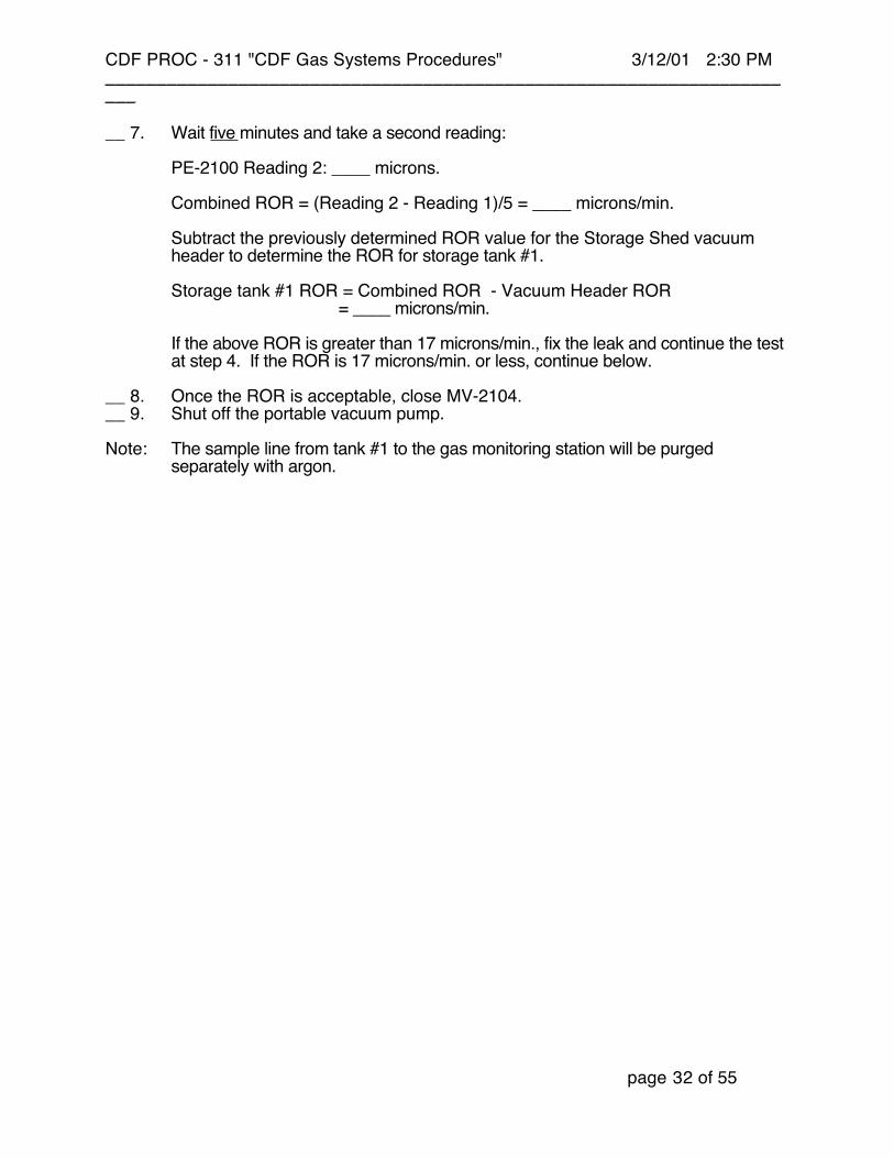
__ 7. Wait five minutes and take a second reading:
PE-2100 Reading 2: ____ microns.
Combined ROR = (Reading 2 - Reading 1)/5 = ____ microns/min.
Subtract the previously determined ROR value for the Storage Shed vacuumheader to determine the ROR for storage tank #1.
Storage tank #1 ROR = Combined ROR - Vacuum Header ROR = ____ microns/min.
If the above ROR is greater than 17 microns/min., fix the leak and continue the testat step 4. If the ROR is 17 microns/min. or less, continue below.
__ 8. Once the ROR is acceptable, close MV-2104.__ 9. Shut off the portable vacuum pump.
Note: The sample line from tank #1 to the gas monitoring station will be purgedseparately with argon.

CDF PROC - 311 "CDF Gas Systems Procedures" 3/12/01 2:30 PM_____________________________________________________________________
page 33 of 55
Storage Tank #2 Evacuation
Name:__________________________ Date:__/__/__ Time:____:____
This procedure evacuates the #2 Gas Shed storage tank.
__ 1. Configure the Gas Storage Shed valves in the following positions:
(√) Valve Position__ MV-2002 Closed__ MV-2003 Open__ MV-2004 Closed__ MV-2016 Closed__ MV-2104 Closed__ PV-2200 (EV-GST2OUT) Closed__ PV-2201 (EV-GST2DRN) Closed__ MV-2202 Open__ PV-2202 (EV-GST2IN) Closed__ MV-2203 Closed__ MV-2204 Closed__ MV-2205 Closed__ MV-2206 Open__ MV-2207 Closed__ MV-2208 Closed__ MV-2304 Closed__ MV-2503 Closed__ MV-2506 Closed__ MV-2603 Closed__ MV-2606 Closed
__ 2. Connect the portable vacuum pump to MV-2002 via a flex hose.__ 3. Start the portable vacuum pump.__ 4. Open MV-2002 and then MV-2204 to begin pumping down storage tank #2.__ 5. Wait for PE-2200 to read 100 microns or less, then close MV-2002.
Perform a ROR measurement on the combined vacuum header and storage tank #1.__ 6. Wait 60 seconds after closing MV-2002 for the system to equalize, then take a
reading:
PE-2200 Reading 1: ____ microns.

CDF PROC - 311 "CDF Gas Systems Procedures" 3/12/01 2:30 PM_____________________________________________________________________
page 34 of 55
__ 7. Wait five minutes and take a second reading:
PE-2200 Reading 2: ____ microns.
Combined ROR = (Reading 2 - Reading 1)/5 = ____ microns/min.
Subtract the previously determined ROR value for the Storage Shed vacuumheader to determine the ROR for storage tank #2.
Storage tank #2 ROR = Combined ROR - Vacuum Header ROR = ____ microns/min.
If the above ROR is greater than 17 microns/min., fix the leak and continue the testat step 4. If the ROR is 17 micron/min. or less, continue below.
__ 8. Once the ROR is acceptable, close MV-2204.__ 9. Shut off the portable vacuum pump.
Note: The sample line from tank #2 to the gas monitoring station will be purgedseparately with argon.
CDF PROC - 311 "CDF Gas Systems Procedures" 3/12/01 2:30 PM_____________________________________________________________________
page 35 of 55
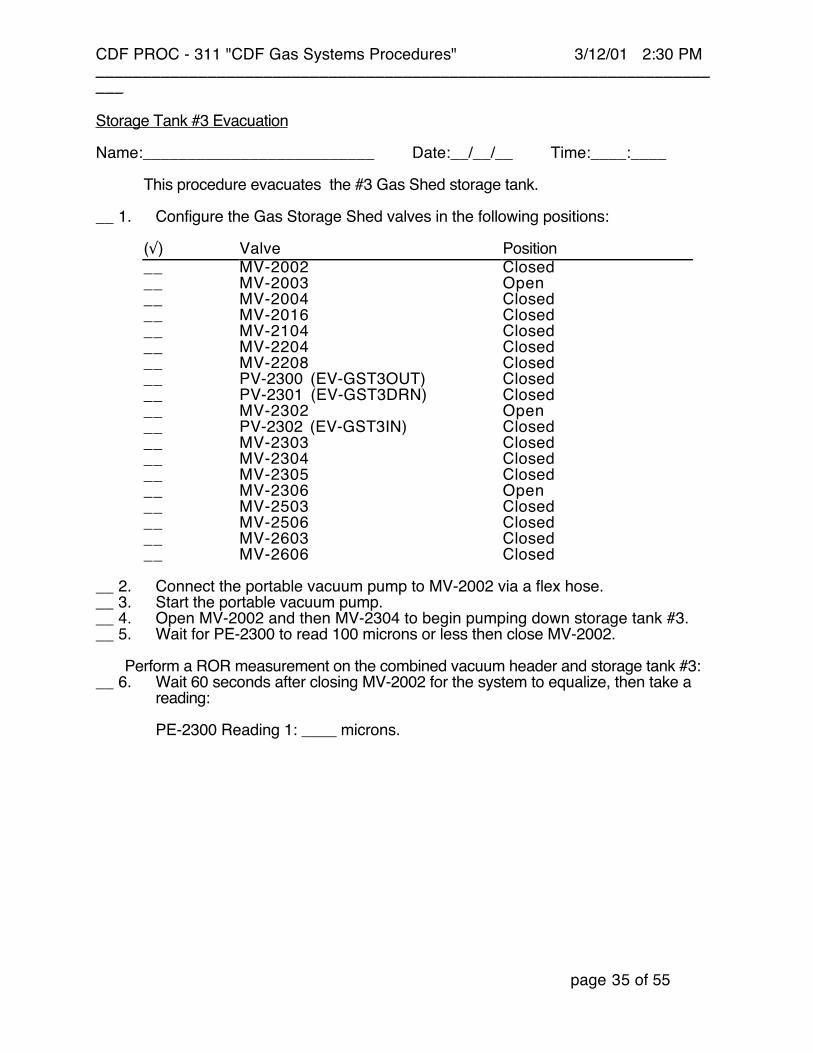
Storage Tank #3 Evacuation
Name:__________________________ Date:__/__/__ Time:____:____
This procedure evacuates the #3 Gas Shed storage tank.
__ 1. Configure the Gas Storage Shed valves in the following positions:
(√) Valve Position__ MV-2002 Closed__ MV-2003 Open__ MV-2004 Closed__ MV-2016 Closed__ MV-2104 Closed__ MV-2204 Closed__ MV-2208 Closed__ PV-2300 (EV-GST3OUT) Closed__ PV-2301 (EV-GST3DRN) Closed__ MV-2302 Open__ PV-2302 (EV-GST3IN) Closed__ MV-2303 Closed__ MV-2304 Closed__ MV-2305 Closed__ MV-2306 Open__ MV-2503 Closed__ MV-2506 Closed__ MV-2603 Closed__ MV-2606 Closed
__ 2. Connect the portable vacuum pump to MV-2002 via a flex hose.__ 3. Start the portable vacuum pump.__ 4. Open MV-2002 and then MV-2304 to begin pumping down storage tank #3.__ 5. Wait for PE-2300 to read 100 microns or less then close MV-2002.
Perform a ROR measurement on the combined vacuum header and storage tank #3:__ 6. Wait 60 seconds after closing MV-2002 for the system to equalize, then take a
reading:
PE-2300 Reading 1: ____ microns.
CDF PROC - 311 "CDF Gas Systems Procedures" 3/12/01 2:30 PM_____________________________________________________________________
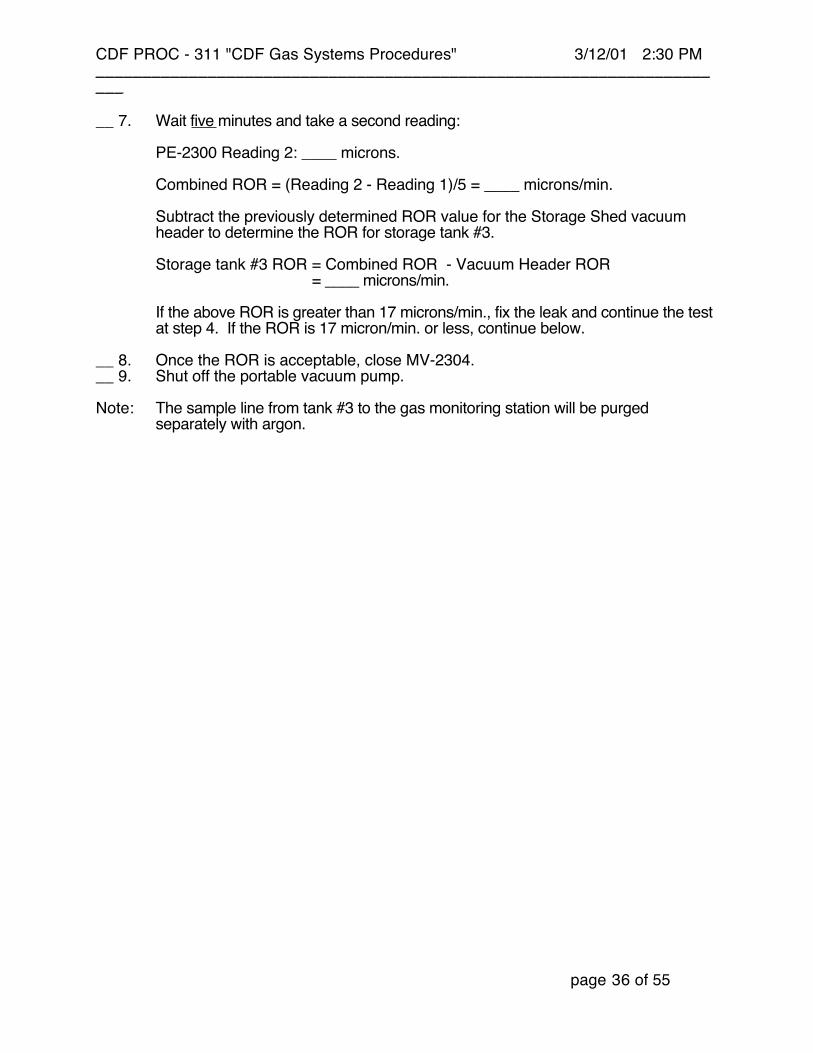
page 36 of 55
__ 7. Wait five minutes and take a second reading:
PE-2300 Reading 2: ____ microns.
Combined ROR = (Reading 2 - Reading 1)/5 = ____ microns/min.
Subtract the previously determined ROR value for the Storage Shed vacuumheader to determine the ROR for storage tank #3.
Storage tank #3 ROR = Combined ROR - Vacuum Header ROR = ____ microns/min.
If the above ROR is greater than 17 microns/min., fix the leak and continue the testat step 4. If the ROR is 17 micron/min. or less, continue below.
__ 8. Once the ROR is acceptable, close MV-2304.__ 9. Shut off the portable vacuum pump.
Note: The sample line from tank #3 to the gas monitoring station will be purgedseparately with argon.
CDF PROC - 311 "CDF Gas Systems Procedures" 3/12/01 2:30 PM_____________________________________________________________________
page 37 of 55
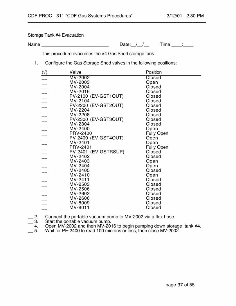
Storage Tank #4 Evacuation
Name:__________________________ Date:__/__/__ Time:____:____
This procedure evacuates the #4 Gas Shed storage tank.
__ 1. Configure the Gas Storage Shed valves in the following positions:
(√) Valve Position__ MV-2002 Closed__ MV-2003 Open__ MV-2004 Closed__ MV-2016 Closed__ PV-2100 (EV-GST1OUT) Closed__ MV-2104 Closed__ PV-2200 (EV-GST2OUT) Closed__ MV-2204 Closed__ MV-2208 Closed__ PV-2300 (EV-GST3OUT) Closed__ MV-2304 Closed__ MV-2400 Open__ PRV-2400 Fully Open__ PV-2400 (EV-GST4OUT) Open__ MV-2401 Open__ PRV-2401 Fully Open__ PV-2401 (EV-GSTRSUP) Closed__ MV-2402 Closed__ MV-2403 Open__ MV-2404 Open__ MV-2405 Closed__ MV-2410 Open__ MV-2411 Closed__ MV-2503 Closed__ MV-2506 Closed__ MV-2603 Closed__ MV-2606 Closed__ MV-8009 Closed__ MV-8011 Closed
__ 2. Connect the portable vacuum pump to MV-2002 via a flex hose.__ 3. Start the portable vacuum pump.__ 4. Open MV-2002 and then MV-2016 to begin pumping down storage tank #4.__ 5. Wait for PE-2400 to read 100 microns or less, then close MV-2002.

CDF PROC - 311 "CDF Gas Systems Procedures" 3/12/01 2:30 PM_____________________________________________________________________
page 38 of 55
Perform a ROR measurement on the combined vacuum header and storage tank #4.__ 6. Wait 60 seconds after closing MV-2002 for the system to equalize, then take a
reading:
PE-2400 Reading 1: ____ microns.
__ 7. Wait five minutes and take a second reading:
PE-2400 Reading 2: ____ microns.
Combined ROR = (Reading 2 - Reading 1)/5 = ____ microns/min.
Subtract the previously determined ROR value for the Storage Shed vacuumheader to determine the ROR for storage tank #4.
Storage tank #4 ROR = Combined ROR - Vacuum Header ROR = ____ microns/min.
If the above ROR is greater than 17 microns/min., fix the leak and continue the testat step 4. If the ROR is 17 micron/min. or less, continue below.
__ 8. Once the ROR is acceptable, close MV-2016.__ 9. Shut off the portable vacuum pump.
Note: The sample lines from tank #4 to the gas monitoring station on the main floor and inthe Mix Shed will be purged separately with argon.

CDF PROC - 311 "CDF Gas Systems Procedures" 3/12/01 2:30 PM_____________________________________________________________________
page 39 of 55
Gas Storage Shed System Backfill
Name:__________________________ Date:__/__/__ Time:____:____
This procedure backfills the previously evacuated lines in the Gas Storage Shedwith argon gas.
__ 1. Close MV-1406, MV-1506, and PV-1709 (EV-MSAEDEL) at the Gas MixingShed.
__ 2. Configure the valves in the Gas Storage Shed in the following positions:
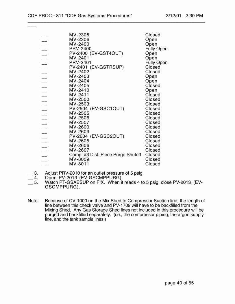
(√) Valve Position__ MV-2001 Closed__ PRV-2002 Fully Open__ MV-2004 Closed__ PV-2005 (EV-GSCMPIN) Open__ MV-2006 Open__ MV-2007 Open__ MV-2008 Open__ PV-2009 (EV-GSCMPBYP) Open__ MV-2010 Open__ MV-2011 Open__ MV-2013 Open__ PV-2013 (EV-GSCMPPURG) Closed__ MV-2016 Closed__ PV-2016 (EV-GSETHCORR) Closed__ PRV-2020 Fully Open__ PV-2026 (EV-GSARCORR) Closed__ PV-2100 (EV-GST1OUT) Open__ PV-2101 (EV-GST1DRN) Open__ MV-2102 Open__ PV-2102 (EV-GST1IN) Open__ MV-2103 Closed__ MV-2104 Closed__ MV-2105 Closed__ MV-2106 Open__ MV-2107 Closed__ PV-2200 (EV-GST2OUT) Open__ PV-2201 (EV-GST2DRN) Open__ MV-2202 Open__ PV-2202 (EV-GST2IN) Open__ MV-2203 Closed__ MV-2204 Closed__ MV-2205 Closed__ MV-2206 Open__ MV-2207 Closed__ PV-2300 (EV-GST3OUT) Open__ PV-2301 (EV-GST3DRN) Open__ MV-2302 Open__ PV-2302 (EV-GST3IN) Open__ MV-2303 Closed__ MV-2304 Closed
CDF PROC - 311 "CDF Gas Systems Procedures" 3/12/01 2:30 PM_____________________________________________________________________
page 40 of 55
__ MV-2305 Closed__ MV-2306 Open__ MV-2400 Open__ PRV-2400 Fully Open__ PV-2400 (EV-GST4OUT) Open__ MV-2401 Open__ PRV-2401 Fully Open__ PV-2401 (EV-GSTRSUP) Closed__ MV-2402 Closed__ MV-2403 Open__ MV-2404 Open__ MV-2405 Closed__ MV-2410 Open__ MV-2411 Closed__ MV-2500 Closed__ MV-2503 Closed__ PV-2504 (EV-GSC1OUT) Closed__ MV-2505 Closed__ MV-2506 Closed__ MV-2507 Closed__ MV-2600 Closed__ MV-2603 Closed__ PV-2604 (EV-GSC2OUT) Closed__ MV-2605 Closed__ MV-2606 Closed__ MV-2607 Closed__ Comp. #3 Dist. Piece Purge Shutoff Closed__ MV-8009 Closed__ MV-8011 Closed
__ 3. Adjust PRV-2010 for an outlet pressure of 5 psig.__ 4. Open PV-2013 (EV-GSCMPPURG).__ 5. Watch PT-GSAESUP on FIX. When it reads 4 to 5 psig, close PV-2013 (EV-
GSCMPPURG).
Note: Because of CV-1000 on the Mix Shed to Compressor Suction line, the length ofline between this check valve and PV-1709 will have to be backfilled from theMixing Shed. Any Gas Storage Shed lines not included in this procedure will bepurged and backfilled separately. (i.e., the compressor piping, the argon supplyline, and the tank sample lines.)

CDF PROC - 311 "CDF Gas Systems Procedures" 3/12/01 2:30 PM_____________________________________________________________________
page 41 of 55
Thermal Conductivity Analyzer Set Up
Name:__________________________ Date:__/__/__ Time:____:____
This procedure sets up the Gow Mac for use.
__ 1. Power the Mix Shed Gow Mac. The Gow Mac must be warmed up for 24 hoursbefore beginning a mix. Normally, it will never be turned off. MV-1720 and MV-1730 must be open.
__ 2. While not in use, the Gow Mac will have gas from Tank number 4 supplying thereference and sample circuits. To accomplish this, PV–1719 (EV-MSAE2GM) isclosed, PV-1720 (EV-MSGG2GM) is closed, PV-1721 (EV-MSGMZERO) isclosed, and PV-1722 (EV-MSGMBYP) is closed. These valves are positionedautomatically by the Moore Products controller.
__ 3. The sample and reference flow controllers should have set points of 50 cc/min.These setpoints are controlled via the Moore Products controller. The actualgas sampling operation is also controlled by the Moore Products controller.
CDF PROC - 311 "CDF Gas Systems Procedures" 3/12/01 2:30 PM_____________________________________________________________________
page 42 of 55
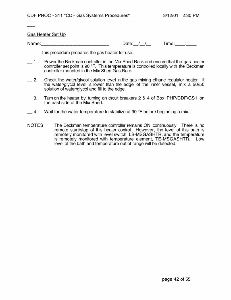
Gas Heater Set Up
Name:__________________________ Date:__/__/__ Time:____:____
This procedure prepares the gas heater for use.
__ 1. Power the Beckman controller in the Mix Shed Rack and ensure that the gas heatercontroller set point is 90 °F. This temperature is controlled locally with the Beckmancontroller mounted in the Mix Shed Gas Rack.
__ 2. Check the water/glycol solution level in the gas mixing ethane regulator heater. Ifthe water/glycol level is lower than the edge of the inner vessel, mix a 50/50solution of water/glycol and fill to the edge.
__ 3. Turn on the heater by turning on circuit breakers 2 & 4 of Box PHP/CDF/GS1 onthe east side of the Mix Shed.
__ 4. Wait for the water temperature to stabilize at 90 °F before beginning a mix.
NOTES: The Beckman temperature controller remains ON continuously. There is noremote start/stop of this heater control. However, the level of this bath isremotely monitored with level switch, LS-MSGASHTR; and the temperatureis remotely monitored with temperature element, TE-MSGASHTR. Lowlevel of the bath and temperature out of range will be detected.

CDF PROC - 311 "CDF Gas Systems Procedures" 3/12/01 2:30 PM_____________________________________________________________________
page 43 of 55
Storage Shed Valve Positioning for Automatic Mixing
Name:__________________________ Date:__/__/__ Time:____:____
This procedure sets all the manual valves in the Gas Storage Shed to their requiredpositions for automatic 50/50 Argon-Ethane gas mixing. All solenoid and pneumatic valvesare automatically positioned with the Moore Products process control systemsprogrammable logic controller. The following manual valves shall not deviate from theindicated positions unless required by an approved procedure.
Gas Storage Shed:
(√) Valve Description Position__ MV 2000 GAS SHED COMP DISCHARGE CLOSED/CAPPED__ MV 2001 GAS SHED COMP DISCHARGE CUT OFF CLOSED__ MV 2003 GAS SHED TANK VACUUM SHUTOFF CLOSED__ MV 2004 GAS SHED VACUUM SHUTOFF CLOSED__ MV 2006 GAS SHED A/E SUPPLY FROM MIX SHED OPEN__ MV 2007 GAS SHED COMP SUC PI/PT & FINAL CORR. ISOL. OPEN__ MV 2008 GAS SHED COMPRESSOR BYPASS CLOSED__ MV 2010 GAS SHED KICKBACK ISOLATION VALVE OPEN__ MV 2011 GAS SHED COMPRESSOR DISCHARGE PI ISOL. OPEN__ MV 2013 GAS SHED COMPRESSOR DISCHARGE VENT CLOSED/CAPPED__ MV 2016 GAS SHED TANK#4 VACUUM LINE CLOSED__ MV 2017 GAS SHED PNEUM. SUPPLY WEST PT ISOL OPEN__ MV 2018 GAS SHED PNEUM. SUPPLY WEST BANK ISOL. Alternate Open with
MV-2019__ MV 2019 GAS SHED PNEUM. SUPPLY EAST BANK ISOL. Alternate Open with
MV-2018__ MV 2020 GAS SHED PNEUM. SUPPLY EAST PT ISOL OPEN__ MV 2021 GAS SHED PNEUM. SUPPLY WEST BOTTLE ISOL. OPEN__ MV 2022 GAS SHED PNEUM. SUPPLY WEST BOTTLE ISOL. OPEN__ MV 2023 GAS SHED PNEUM. SUPPLY WEST BOTTLE ISOL. OPEN__ MV 2024 GAS SHED PNEUM. SUPPLY WEST BOTTLE ISOL. OPEN__ MV 2025 GAS SHED PNEUM. SUPPLY EAST BOTTLE ISOL. OPEN__ MV 2026 GAS SHED PNEUM. SUPPLY EAST BOTTLE ISOL. OPEN__ MV 2027 GAS SHED PNEUM. SUPPLY EAST BOTTLE ISOL. OPEN__ MV 2028 GAS SHED PNEUM. SUPPLY EAST BOTTLE ISOL. OPEN__ MV 2029 GAS SHED PNEUM. SUPPLY PT ISOL. OPEN__ MV 2042 GAS SHED NITROGEN BACK-UP BOTTLE ISOL. OPEN__ MV 2043 GAS SHED ARGON LINE OPEN__ MV 2102 GAS SHED TANK#1 VACUUM LINE CLOSED__ MV 2103 GAS SHED TANK#1 VACUUM LINE CLOSED/CAPPED__ MV 2104 GAS SHED TANK#1 VACUUM LINE SHUTOFF CLOSED__ MV 2105 GAS SHED TANK#1 MONITORING LINE SHUTOFF OPEN__ MV 2106 GAS SHED TANK#1 DRAIN LINE PI ISOL. OPEN__ MV 2107 GAS SHED TANK#1 VENT CLOSED/CAPPED__ MV 2202 GAS SHED TANK#2 VACUUM LINE CLOSED__ MV 2203 GAS SHED TANK#2 VACUUM LINE CLOSED/CAPPED
CDF PROC - 311 "CDF Gas Systems Procedures" 3/12/01 2:30 PM_____________________________________________________________________
page 44 of 55
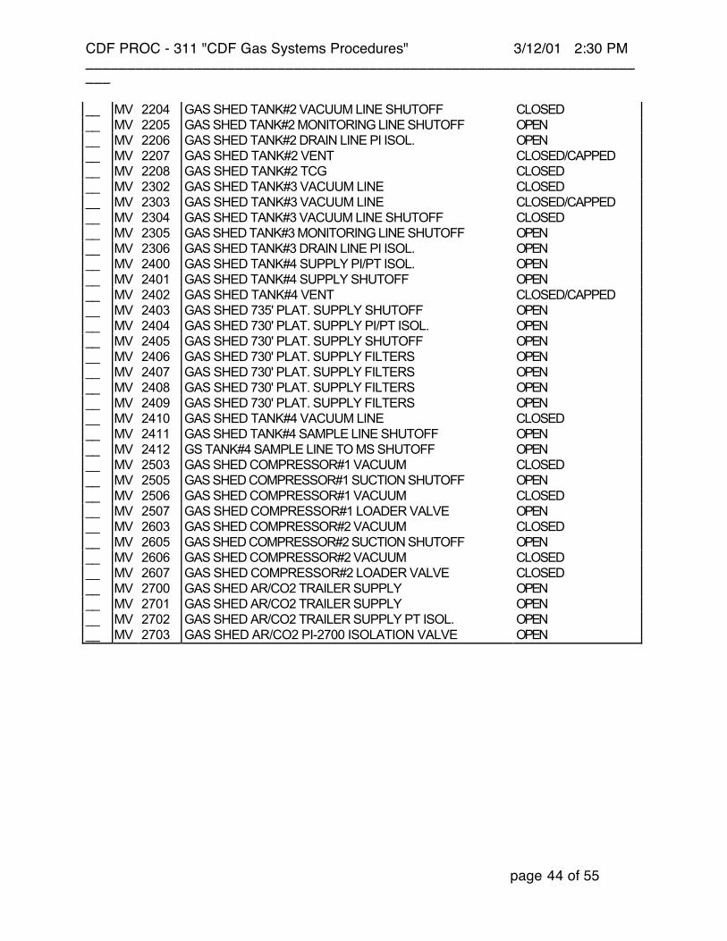
__ MV 2204 GAS SHED TANK#2 VACUUM LINE SHUTOFF CLOSED__ MV 2205 GAS SHED TANK#2 MONITORING LINE SHUTOFF OPEN__ MV 2206 GAS SHED TANK#2 DRAIN LINE PI ISOL. OPEN__ MV 2207 GAS SHED TANK#2 VENT CLOSED/CAPPED__ MV 2208 GAS SHED TANK#2 TCG CLOSED__ MV 2302 GAS SHED TANK#3 VACUUM LINE CLOSED__ MV 2303 GAS SHED TANK#3 VACUUM LINE CLOSED/CAPPED__ MV 2304 GAS SHED TANK#3 VACUUM LINE SHUTOFF CLOSED__ MV 2305 GAS SHED TANK#3 MONITORING LINE SHUTOFF OPEN__ MV 2306 GAS SHED TANK#3 DRAIN LINE PI ISOL. OPEN__ MV 2400 GAS SHED TANK#4 SUPPLY PI/PT ISOL. OPEN__ MV 2401 GAS SHED TANK#4 SUPPLY SHUTOFF OPEN__ MV 2402 GAS SHED TANK#4 VENT CLOSED/CAPPED__ MV 2403 GAS SHED 735' PLAT. SUPPLY SHUTOFF OPEN__ MV 2404 GAS SHED 730' PLAT. SUPPLY PI/PT ISOL. OPEN__ MV 2405 GAS SHED 730' PLAT. SUPPLY SHUTOFF OPEN__ MV 2406 GAS SHED 730' PLAT. SUPPLY FILTERS OPEN__ MV 2407 GAS SHED 730' PLAT. SUPPLY FILTERS OPEN__ MV 2408 GAS SHED 730' PLAT. SUPPLY FILTERS OPEN__ MV 2409 GAS SHED 730' PLAT. SUPPLY FILTERS OPEN__ MV 2410 GAS SHED TANK#4 VACUUM LINE CLOSED__ MV 2411 GAS SHED TANK#4 SAMPLE LINE SHUTOFF OPEN__ MV 2412 GS TANK#4 SAMPLE LINE TO MS SHUTOFF OPEN__ MV 2503 GAS SHED COMPRESSOR#1 VACUUM CLOSED__ MV 2505 GAS SHED COMPRESSOR#1 SUCTION SHUTOFF OPEN__ MV 2506 GAS SHED COMPRESSOR#1 VACUUM CLOSED__ MV 2507 GAS SHED COMPRESSOR#1 LOADER VALVE OPEN__ MV 2603 GAS SHED COMPRESSOR#2 VACUUM CLOSED__ MV 2605 GAS SHED COMPRESSOR#2 SUCTION SHUTOFF OPEN__ MV 2606 GAS SHED COMPRESSOR#2 VACUUM CLOSED__ MV 2607 GAS SHED COMPRESSOR#2 LOADER VALVE CLOSED__ MV 2700 GAS SHED AR/CO2 TRAILER SUPPLY OPEN__ MV 2701 GAS SHED AR/CO2 TRAILER SUPPLY OPEN__ MV 2702 GAS SHED AR/CO2 TRAILER SUPPLY PT ISOL. OPEN__ MV 2703 GAS SHED AR/CO2 PI-2700 ISOLATION VALVE OPEN

CDF PROC - 311 "CDF Gas Systems Procedures" 3/12/01 2:30 PM_____________________________________________________________________
page 45 of 55
Mixing Shed Valve Positioning for Automatic Mixing
Name:__________________________ Date:__/__/__ Time:____:____
This procedure sets all the manual valves in the Gas Mixing Shed to their required positionsfor automatic 50/50 Argon-Ethane gas mixing. All solenoid and pneumatic valves areautomatically positioned with the Moore Products process control systems programmablelogic controller. The following manual valves shall not deviate from the indicated positionsunless required by an approved procedure.
Mixing Shed:
(√) Valve Description Position__ MV 1100 MS ETHANE TR.#1 BLEED CLOSED/CAPPED__ MV 1102 MS ETHANE TR.#1 GAGE ISOL. OPEN__ MV 1103 MS ETHANE TR.#1 VENT CLOSED__ MV 1104 MS ETHANE TR.#1 VACUUM HEADER CLOSED__ MV 1105 MS ETHANE TR.#1 SAMPLE CLOSED/CAPPED__ MV 1106 MS ETHANE TR.#1 PT ISOLATION OPEN__ MV 1107 MS ETHANE TR.#1 STRAINER BYPASS CLOSED__ MV 1108 MS ETHANE TR.#1 STRAINER VENT CLOSED/CAPPED__ MV 1200 MS ETHANE TR.#2 BLEED CLOSED/CAPPED__ MV 1202 MS ETHANE TR.#2 GAGE ISOL. OPEN__ MV 1203 MS ETHANE TR.#2 SAMPLE CLOSED__ MV 1204 MS ETHANE TR.#2 VACUUM HEADER CLOSED__ MV 1205 MS ETHANE TR.#2 SAMPLE CLOSED/CAPPED__ MV 1206 MS ETHANE TR.#2 PT ISOLATION OPEN__ MV 1207 MS ETHANE TR.#2 STRAINER BYPASS CLOSED__ MV 1208 MS ETHANE TR.#2 STRAINER VENT CLOSED/CAPPED__ MV 1300 MS ETHANE TR.#3 BLEED CLOSED/CAPPED__ MV 1302 MS ETHANE TR.#3 GAGE ISOL. OPEN__ MV 1303 MS ETHANE TR.#3 BLEED CLOSED__ MV 1304 MS ETHANE TR.#3 VACUUM HEADER CLOSED__ MV 1305 MS ETHANE TR.#3 SAMP. CLOSED/CAPPED__ MV 1306 MS ETHANE TR.#3 PT ISOLATION OPEN__ MV 1307 MS ETHANE TR.#3 STRAINER BYPASS CLOSED__ MV 1308 MS ETHANE TR.#3 STRAINER VENT CLOSED/CAPPED__ MV 1400 MS ETHANE TR.#4 BLEED CLOSED/CAPPED__ MV 1401 MS ETHANE TR.#4 SUPPLY ISOL. CLOSED__ MV 1402 MS EHTANE TR.#4 PRESSURE GAGE ISOL. CLOSED__ MV 1403 MS ETHANE TR.#4 BLEED CLOSED/CAPPED__ MV 1404 MS ETHANE TR.#4 SAMP. CLOSED__ MV 1405 MS ETHANE TR.#4 VACUUM CLOSED__ MV 1406 MS ETHANE TR.#4 COMP.SUC. CLOSED__ MV 1407 MS ETHANE TR.#4 COMP.DISC. CLOSED

CDF PROC - 311 "CDF Gas Systems Procedures" 3/12/01 2:30 PM_____________________________________________________________________
page 46 of 55
__ MV 1500 MS ETHANE TR.#5 BLEED CLOSED/CAPPED__ MV 1501 MS ETHANE TR.#5 SUPPLY ISOL. CLOSED__ MV 1502 MS ETHANE TR.#5 PRESSURE GAGE ISOL. CLOSED__ MV 1503 MS ETHANE TR.#5 BLEED CLOSED/CAPPED__ MV 1504 MS ETHANE TR.#5 SAMP. CLOSED__ MV 1505 MS ETHANE TR.#5 VACUUM CLOSED__ MV 1506 MS ETHANE TR.#5 COMP.SUC. CLOSED__ MV 1507 MS ETHANE TR.#5 COMP.DISC. CLOSED__ MV 1600 MS 95/5 TRAILER SLOT#6 TO PT 1600 OPEN__ MV 1601 MS 95/5 TRAILER SLOT#6 VENT CLOSED__ MV 1602 MS 95/5 TRAILER SLOT#6 SHUT-OFF Alternate Open with
MV-1605__ MV 1603 MS 95/5 TRAILER SLOT#7 TO PT 1601 OPEN__ MV 1604 MS 95/5 TRAILER SLOT#7 VENT CLOSED__ MV 1605 MS 95/5 TRAILER SLOT#7 SHUT-OFF Alternate Open with
MV-1602__ MV 1606 MS PI-1606 ISOLATE, Ar/CO2 line OPEN__ MV 1700 MS H2S ADSORBER ETHANE IN OPEN__ MV 1701 MS TANK #4 SAMPLE LINE TO GOW MAC OPEN__ MV 1702 MS H2S ADSORBER ETHANE VENT OPEN__ MV 1705 MS H2S ADSORBER GAGE ISOL. OPEN__ MV 1706 MS H2S ADSORBER(NIT.IN) OPEN__ MV 1707 MS H2S Adsorber Bypass CLOSED__ MV 1708 MS VACUUM PUMP PURGE SUPPLY OPEN__ MV 1711 MS VACUUM GAGE ISOL. OPEN__ MV 1713 MS VACUUM MANIFOLD CLOSED__ MV 1714 MS F-1713 Oil Drain, supplied with oil vapor filter Self-positioning with
Float__ MV 1715 MS VACUUM GAGE ISOL. OPEN__ MV 1716 MS VACUUM MANIFOLD CLOSED__ MV 1718 MS VACUUM MANIFOLD CLOSED__ MV 1720 MS Gow Mac Reference Port Shutoff OPEN__ MV 1721 MS H2S Adsorber Supply OPEN__ MV 1722 MS H2S Adsorber Exit OPEN__ MV 1724 MS VAC./FLOW CONTROL RK CLOSED__ MV 1730 MS Gow Mac Sample Port Shutoff OPEN__ MV 1731 MS VAC./FLOW CONTROL RK CLOSED__ MV 1732 MS VAC./FLOW CONTROL RK CLOSED__ MV 1734 MS VAC./FLOW CONTROL RK CLOSED__ MV 1740 MS PT-MSAFCSUP ISOLATE OPEN__ MV 1741 MS PT-MSEFCSUP ISOLATE OPEN__ MV 1750 MS Oil Filtration Supply OPEN__ MV 1751 MS Oil Filtration Exit OPEN__ MV 1752 MS Oil Filtration Bypass Valve CLOSED__ MV 1753 MS Oil Filtration Vent Valve CLOSED__ MV 1754 MS Oil Reservoir Isolation Valve OPEN
CDF PROC - 311 "CDF Gas Systems Procedures" 3/12/01 2:30 PM_____________________________________________________________________
page 47 of 55
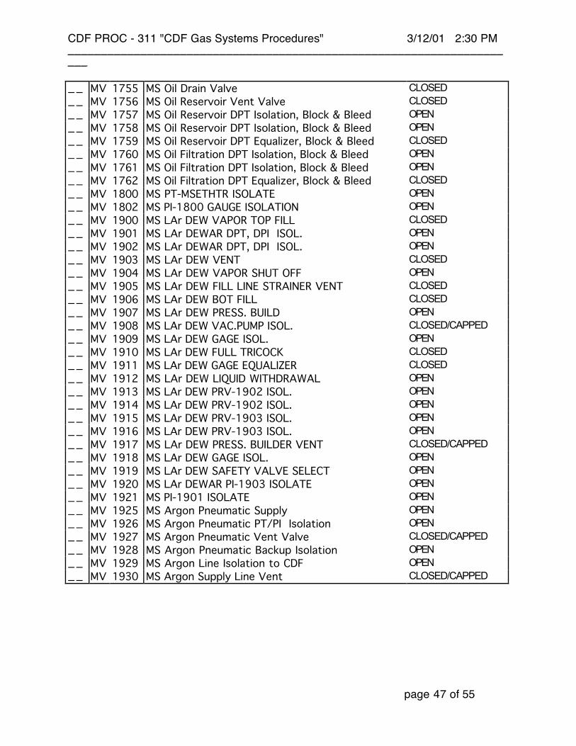
__ MV 1755 MS Oil Drain Valve CLOSED__ MV 1756 MS Oil Reservoir Vent Valve CLOSED__ MV 1757 MS Oil Reservoir DPT Isolation, Block & Bleed OPEN__ MV 1758 MS Oil Reservoir DPT Isolation, Block & Bleed OPEN__ MV 1759 MS Oil Reservoir DPT Equalizer, Block & Bleed CLOSED__ MV 1760 MS Oil Filtration DPT Isolation, Block & Bleed OPEN__ MV 1761 MS Oil Filtration DPT Isolation, Block & Bleed OPEN__ MV 1762 MS Oil Filtration DPT Equalizer, Block & Bleed CLOSED__ MV 1800 MS PT-MSETHTR ISOLATE OPEN__ MV 1802 MS PI-1800 GAUGE ISOLATION OPEN__ MV 1900 MS LAr DEW VAPOR TOP FILL CLOSED__ MV 1901 MS LAr DEWAR DPT, DPI ISOL. OPEN__ MV 1902 MS LAr DEWAR DPT, DPI ISOL. OPEN__ MV 1903 MS LAr DEW VENT CLOSED__ MV 1904 MS LAr DEW VAPOR SHUT OFF OPEN__ MV 1905 MS LAr DEW FILL LINE STRAINER VENT CLOSED__ MV 1906 MS LAr DEW BOT FILL CLOSED__ MV 1907 MS LAr DEW PRESS. BUILD OPEN__ MV 1908 MS LAr DEW VAC.PUMP ISOL. CLOSED/CAPPED__ MV 1909 MS LAr DEW GAGE ISOL. OPEN__ MV 1910 MS LAr DEW FULL TRICOCK CLOSED__ MV 1911 MS LAr DEW GAGE EQUALIZER CLOSED__ MV 1912 MS LAr DEW LIQUID WITHDRAWAL OPEN__ MV 1913 MS LAr DEW PRV-1902 ISOL. OPEN__ MV 1914 MS LAr DEW PRV-1902 ISOL. OPEN__ MV 1915 MS LAr DEW PRV-1903 ISOL. OPEN__ MV 1916 MS LAr DEW PRV-1903 ISOL. OPEN__ MV 1917 MS LAr DEW PRESS. BUILDER VENT CLOSED/CAPPED__ MV 1918 MS LAr DEW GAGE ISOL. OPEN__ MV 1919 MS LAr DEW SAFETY VALVE SELECT OPEN__ MV 1920 MS LAr DEWAR PI-1903 ISOLATE OPEN__ MV 1921 MS PI-1901 ISOLATE OPEN__ MV 1925 MS Argon Pneumatic Supply OPEN__ MV 1926 MS Argon Pneumatic PT/PI Isolation OPEN__ MV 1927 MS Argon Pneumatic Vent Valve CLOSED/CAPPED__ MV 1928 MS Argon Pneumatic Backup Isolation OPEN__ MV 1929 MS Argon Line Isolation to CDF OPEN__ MV 1930 MS Argon Supply Line Vent CLOSED/CAPPED
CDF PROC - 311 "CDF Gas Systems Procedures" 3/12/01 2:30 PM_____________________________________________________________________
page 48 of 55
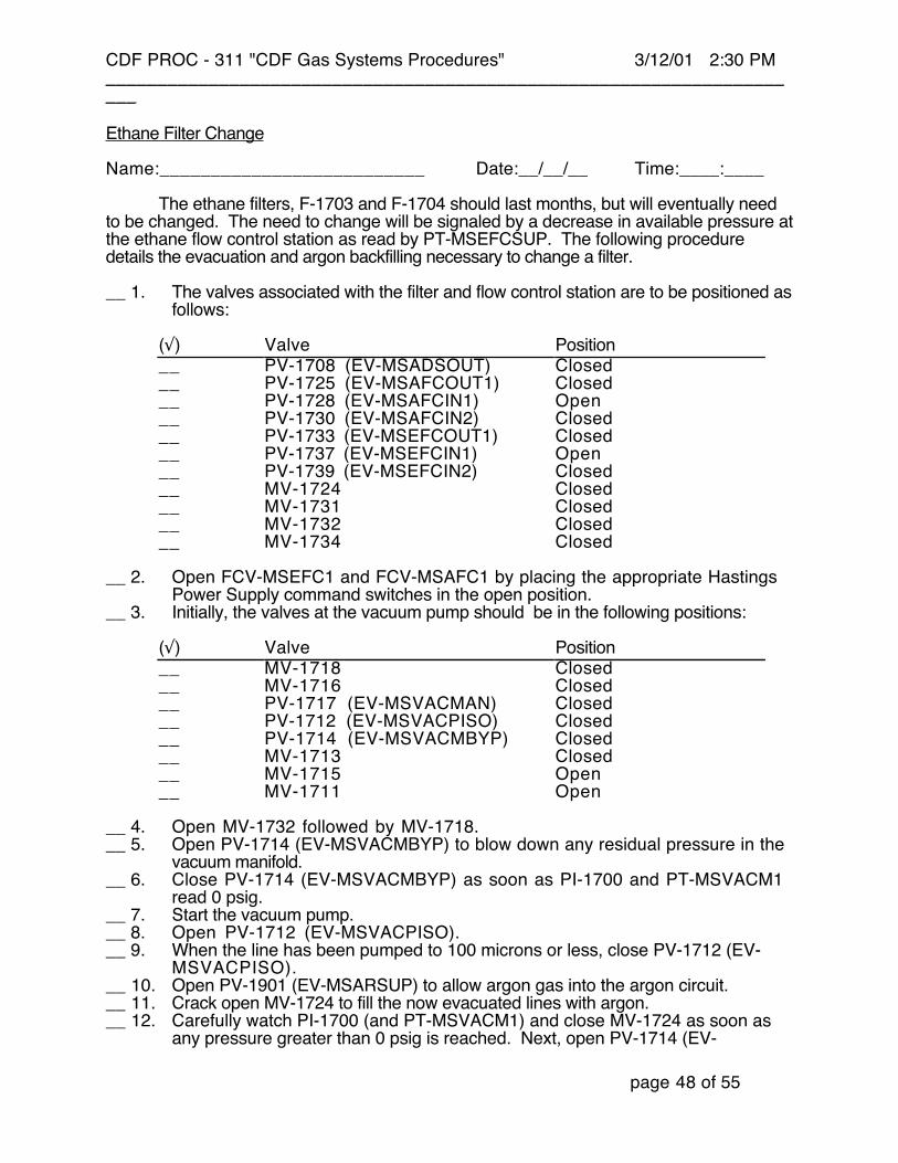
Ethane Filter Change
Name:__________________________ Date:__/__/__ Time:____:____
The ethane filters, F-1703 and F-1704 should last months, but will eventually needto be changed. The need to change will be signaled by a decrease in available pressure atthe ethane flow control station as read by PT-MSEFCSUP. The following proceduredetails the evacuation and argon backfilling necessary to change a filter.
__ 1. The valves associated with the filter and flow control station are to be positioned asfollows:
(√) Valve Position__ PV-1708 (EV-MSADSOUT) Closed__ PV-1725 (EV-MSAFCOUT1) Closed__ PV-1728 (EV-MSAFCIN1) Open__ PV-1730 (EV-MSAFCIN2) Closed__ PV-1733 (EV-MSEFCOUT1) Closed__ PV-1737 (EV-MSEFCIN1) Open__ PV-1739 (EV-MSEFCIN2) Closed__ MV-1724 Closed__ MV-1731 Closed__ MV-1732 Closed__ MV-1734 Closed
__ 2. Open FCV-MSEFC1 and FCV-MSAFC1 by placing the appropriate HastingsPower Supply command switches in the open position.
__ 3. Initially, the valves at the vacuum pump should be in the following positions:
(√) Valve Position__ MV-1718 Closed__ MV-1716 Closed__ PV-1717 (EV-MSVACMAN) Closed__ PV-1712 (EV-MSVACPISO) Closed__ PV-1714 (EV-MSVACMBYP) Closed__ MV-1713 Closed__ MV-1715 Open__ MV-1711 Open
__ 4. Open MV-1732 followed by MV-1718.__ 5. Open PV-1714 (EV-MSVACMBYP) to blow down any residual pressure in the
vacuum manifold.__ 6. Close PV-1714 (EV-MSVACMBYP) as soon as PI-1700 and PT-MSVACM1
read 0 psig.__ 7. Start the vacuum pump.__ 8. Open PV-1712 (EV-MSVACPISO).__ 9. When the line has been pumped to 100 microns or less, close PV-1712 (EV-
MSVACPISO).__ 10. Open PV-1901 (EV-MSARSUP) to allow argon gas into the argon circuit.__ 11. Crack open MV-1724 to fill the now evacuated lines with argon.__ 12. Carefully watch PI-1700 (and PT-MSVACM1) and close MV-1724 as soon as
any pressure greater than 0 psig is reached. Next, open PV-1714 (EV-

CDF PROC - 311 "CDF Gas Systems Procedures" 3/12/01 2:30 PM_____________________________________________________________________
page 49 of 55
MSVACMBYP) to bleed off the pressure. Then, close again PV-1714 (EV-MSVACMBYP).
__ 13. Now that the portion of the ethane circuit which includes the two filters is filled withargon, disassemble the filter housings, and replace the cartridges. Model numbersfor the cartridges are listed in the CDF Gas Systems Valve and Instrument List.Reassemble the housings.
__ 14. Open PV-1712 (EV-MSVACPISO) to apply a vacuum to the piping and filter.__ 15. Once 100 microns is reached, close MV-1718 and MV-1732.__ 16. Close PV-1712 (EV-MSVACPISO) and turn off the vacuum pump.__ 17. Open PV-1708 (EV-MSADSOUT) to let ethane fill the now evacuated filter and
supply line.__ 18. Return FCV-MSEFC1 and FCV-MSAFC1 to the auto position.__ 19. Close PV-1728 (EV-MSAFCIN1) and PV-1901 (EV-MSARSUP).__ 20. Close PV-1737 (EV-MSEFCIN1) and PV-1708 (EV-MSADSOUT).
CDF PROC - 311 "CDF Gas Systems Procedures" 3/12/01 2:30 PM_____________________________________________________________________
page 50 of 55
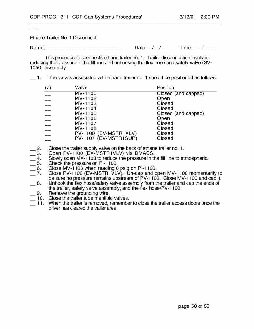
Ethane Trailer No. 1 Disconnect
Name:__________________________ Date:__/__/__ Time:____:____
This procedure disconnects ethane trailer no. 1. Trailer disconnection involvesreducing the pressure in the fill line and unhooking the flex hose and safety valve (SV-1050) assembly.
__ 1. The valves associated with ethane trailer no. 1 should be positioned as follows:
(√) Valve Position__ MV-1100 Closed (and capped)__ MV-1102 Open__ MV-1103 Closed__ MV-1104 Closed__ MV-1105 Closed (and capped)__ MV-1106 Open__ MV-1107 Closed__ MV-1108 Closed__ PV-1100 (EV-MSTR1VLV) Closed__ PV-1107 (EV-MSTR1SUP) Closed
__ 2. Close the trailer supply valve on the back of ethane trailer no. 1.__ 3. Open PV-1100 (EV-MSTR1VLV) via DMACS.__ 4. Slowly open MV-1103 to reduce the pressure in the fill line to atmospheric.__ 5. Check the pressure on PI-1100.__ 6. Close MV-1103 when reading 0 psig on PI-1100.__ 7. Close PV-1100 (EV-MSTR1VLV). Un-cap and open MV-1100 momentarily to
be sure no pressure remains upstream of PV-1100. Close MV-1100 and cap it.__ 8. Unhook the flex hose/safety valve assembly from the trailer and cap the ends of
the trailer, safety valve assembly, and the flex hose/PV-1100.__ 9. Remove the grounding wire.__ 10. Close the trailer tube manifold valves.__ 11. When the trailer is removed, remember to close the trailer access doors once the
driver has cleared the trailer area.

CDF PROC - 311 "CDF Gas Systems Procedures" 3/12/01 2:30 PM_____________________________________________________________________
page 51 of 55
Ethane Trailer No. 2 Disconnect
Name:__________________________ Date:__/__/__ Time:____:____
This procedure disconnects ethane trailer no. 2. Trailer disconnection involvesreducing the pressure in the fill line and unhooking the flex hose and safety valve (SV-1050) assembly.
__ 1. The valves associated with ethane trailer no. 2 should be positioned as follows:
(√) Valve Position__ MV-1200 Closed (and capped)__ MV-1202 Open__ MV-1203 Closed__ MV-1204 Closed__ MV-1205 Closed (and capped)__ MV-1206 Open__ MV-1207 Closed__ MV-1208 Closed__ PV-1200 (EV-MSTR2VLV) Closed__ PV-1207 (EV-MSTR2SUP) Closed
__ 2. Close the trailer supply valve on the back of ethane trailer no. 2.__ 3. Open PV-1200 (EV-MSTR2VLV) via DMACS.__ 4. Slowly open MV-1203 to reduce the pressure in the fill line to atmospheric.__ 5. Check the pressure on PI-1200.__ 6. Close MV-1203 when reading 0 psig on PI-1200.__ 7. Close PV-1200 (EV-MSTR2VLV). Un-cap and open MV-1200 momentarily to
be sure no pressure remains upstream of PV-1200. Close MV-1200 and cap it.__ 8. Unhook the flex hose/safety valve assembly from the trailer and cap the ends of
the trailer, safety valve assembly, and the flex hose/PV-1200.__ 9. Remove the grounding wire.__ 10. Close the trailer tube manifold valves.__ 11. When the trailer is removed, remember to close the trailer access doors once the
driver has cleared the trailer area.

CDF PROC - 311 "CDF Gas Systems Procedures" 3/12/01 2:30 PM_____________________________________________________________________
page 52 of 55
Ethane Trailer No. 3 Disconnect
Name:__________________________ Date:__/__/__ Time:____:____
This procedure disconnects ethane trailer no. 3. Trailer disconnection involvesreducing the pressure in the fill line and unhooking the flex hose and safety valve (SV-1050) assembly.
__ 1. The valves associated with ethane trailer no. 3 should be positioned as follows:
(√) Valve Position__ MV-1300 Closed (and capped)__ MV-1302 Open__ MV-1303 Closed__ MV-1304 Closed__ MV-1305 Closed (and capped)__ MV-1306 Open__ MV-1307 Closed__ MV-1308 Closed__ PV-1300 (EV-MSTR3VLV) Closed__ PV-1307 (EV-MSTR3SUP) Closed
__ 2. Close the trailer supply valve on the back of ethane trailer no. 3.__ 3. Open PV-1300 (EV-MSTR3VLV) via DMACS.__ 4. Slowly open MV-1303 to reduce the pressure in the fill line to atmospheric.__ 5. Check the pressure on PI-1300.__ 6. Close MV-1303 when reading 0 psig on PI-1300.__ 7. Close PV-1300 (EV-MSTR3VLV). Un-cap and open MV-1300 momentarily to
be sure no pressure remains upstream of PV-1300. Close MV-1300 and cap it.__ 8. Unhook the flex hose/safety valve assembly from the trailer and cap the ends of
the trailer, safety valve assembly, and the flex hose/PV-1300.__ 9. Remove the grounding wire.__ 10. Close the trailer tube manifold valves.__ 11. When the trailer is removed, remember to close the trailer access doors once the
driver has cleared the trailer area.
CDF PROC - 311 "CDF Gas Systems Procedures" 3/12/01 2:30 PM_____________________________________________________________________
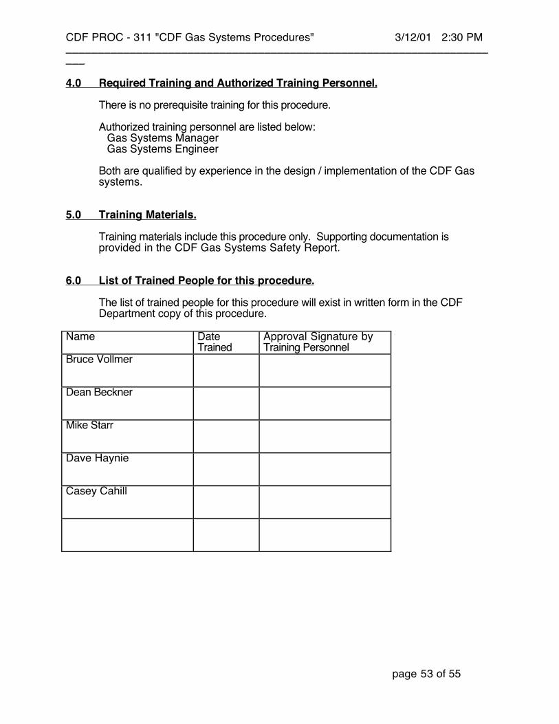
page 53 of 55
4.0 Required Training and Authorized Training Personnel.
There is no prerequisite training for this procedure.
Authorized training personnel are listed below:Gas Systems ManagerGas Systems Engineer
Both are qualified by experience in the design / implementation of the CDF Gassystems.
5.0 Training Materials.
Training materials include this procedure only. Supporting documentation isprovided in the CDF Gas Systems Safety Report.
6.0 List of Trained People for this procedure.
The list of trained people for this procedure will exist in written form in the CDFDepartment copy of this procedure.
Name DateTrained
Approval Signature byTraining Personnel
Bruce Vollmer
Dean Beckner
Mike Starr
Dave Haynie
Casey Cahill