CD System (25 A - 40 A) - Home - Hem - Siemens i Sverige ... more accurate centring, the CD-GP...
24
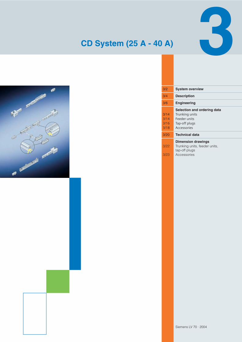
Siemens LV 70 · 2004 3/2 System overview 3/4 Description 3/6 Engineering Selection and ordering data 3/14 Trunking units 3/14 Feeder units 3/16 Tap-off plugs 3/18 Accessories 3/20 Technical data Dimension drawings 3/22 Trunking units, feeder units, tap-off plugs 3/23 Accessories CD System (25 A - 40 A)
Transcript of CD System (25 A - 40 A) - Home - Hem - Siemens i Sverige ... more accurate centring, the CD-GP...
Siemens LV 70 · 2004
3/2 System overview
3/4 Description
3/6 Engineering
Selection and ordering data3/14 Trunking units3/14 Feeder units3/16 Tap-off plugs3/18 Accessories
3/20 Technical data
Dimension drawings3/22 Trunking units, feeder units,
tap-off plugs3/23 Accessories
CD System (25 A - 40 A)

System Overview
Siemens LV 70 · 20043/2
CD System (25 A - 40 A)
3
4
3
2
1
5 4
4
3

System Overview
Siemens LV 70 · 2004 3/3
CD System (25 A - 40 A)
3
1 Trunking units3-, 4-, 5-conductor systemDegree of protection IP54Tap-offs on one side:2 or 3 tap-off points at 1 m intervals,5 tap-off points at 0.5 m intervalsTap-offs on both sides:2, 3 or 5 tap-off points at intervals of 0.5 or 1 m2 m and 3 m lengthsPlug-in connectionTap-off points can be coded
a Page 3/14
2 Feeder unitsEntry feeder unitsEnd feeder units
a Page 3/14
3 AccessoriesFixing bracketSuspension hookSuspension bracketCable fixingCoding set
a Page 3/18
4 Tap-off plugs3-pole, 10 and 16 APhase sequence L1, L2 or L3 with N and PE can be changed by repositioning the contacts.5-pole, 10 A and 16 AL1, L2, L3, N, PECan be coded
a Page 3/16
5 End flange
a Page 3/19

DescriptionCD System (25 A - 40 A)
Siemens LV 70 · 20043/4
3
• Type-tested low-voltage switchgear and controlgear assembly (TTA) to IEC/EN 60 439 -1 and -2
• Reduced planning costs through simplified engineering• Quick-release plug-in connection for fast assembly• Tap-off points on both sides for optimized utilization of the busbar• Even electrical loading of the CD system conductors by connecting an equal num-
ber of tap-off plugs to each individual phase• Versatility through high degree of protection to IP54 of the standard version• Tap-off plugs allow fast, flexible load relocation.
a Locating sectionb Connection terminalc Tap-off point
The trunking units are available in lengths of 2 m and 3 m. They consist of a rectangular, galvanized metal housing with a white-grey paint finish.
They are fitted with the following conductor runs on one or both sides:• 2 for L1 + N (PE = housing)• 3 for L1 + L2 + N (PE = housing)• 4 for L1 + L2 + L3 + N (PE = housing)
The tap-off points are spaced at regular intervals of 0.5 or 1 m on the trunking unit.
The trunking unit housing acts as the PE conductor. Three current ratings are available: 2 25 A, 30 A, 40 A. All trunking units have touch-proof tap-off points, that can be coded by the user.
The trunking units, including those with feeder units and flanges, are assembled wi-thout tools by straightforward plug-in connection.The PE path is established automatically when the housings are connected.An interlock mechanism with two fixings prevents a loosening of the connections between the trunking units, feeder units and flanges.No expansion compensation is required.
These flanges provide protection against direct contact at the ends of the busbar run. They are suitable for use with all CD systems.
Two variants are available:• Entry feeder unit for 2 25 A, 30 A and 40 A• End feeder unit for 2 25 A, 30 A and 40 A.One end flange is included as standard with each unit.Cable entry from three sides. Use metric M25 or M32 plastic cable glands with strain relief (not included as standard).
The tap-off points on the trunking units accept insulated enclosed tap-off plugs.
The following versions are available:• 3-pole and 5-pole versions without fuse base with halogen-free, flame-retardant
cable.• 3-pole and 5-pole version without fuse base with terminal and plastic M20 cable
grommet.• 3-pole version with fuse base for 8.5 mm 31.5 mm type gG (IEC) and type gL
(VDE) fast cylinder fuses, with halogen-free, flame-retardant cable.• 3-pole and 5-pole versions with fuse bases for one or three 8.5 mm 31.5 mm
type gG (IEC) and type gL (VDE) fast cylinder fuses; with terminal and plastic M20 cable grommet.
The 3-pole tap-off plugs have a variable phase tap-off, i.e. they can be connected to L1, L2 or L3.
Features
Trunking units
Connection method
Single conductor run:tap-off points at intervalsof 0.5 m or 1 m
Two conductor runs:tap-off points at intervalsof 0.5 m or 1 m
End flanges
Feeder units
Tap-off plugs

DescriptionCD System (25 A - 40 A)
Siemens LV 70 · 2004 3/5
3
The phase tap-off can therefore be changed by simply changing the contacts to another terminal.
On the 5-pole tap-off plugs, the phase tap-off can not be changed.
The phase assignment of the tap-off plugs is visible from the outside.
Tap-off plugs with terminals accept cables up to 2.5 mm2.
Underfloor mounting Fixing bracket for underfloor mounting
CodingCoding can be used for various frequencies and voltages. It can be retrofitted to the CD-K-... trunking units and the CD-K-A... tap-off plugs. Three code settings are possible: CD-K1 (K2, K3).
SuspensionThe trunking unit profile allows attachment of the suspension and fixing brackets at any point of the trunking unit.
Fixing bracket for trunking units and suspension bracket for luminaires up to max. 20 kg (5-fold safety to DIN 49 980).For more accurate centring, the CD-GP threaded plate can be used.
Fixing bracket for suspending trunking units and for increasedmechanical rigidity at the trunking unit connection points.
Clip-type fixing bracket for suspension from the trunking unit and for mounting lu-minaires (for luminaires up to max. 20 kg at 5-fold safety to DIN 49 980). Also al-lows cables to be routed alongside the system at a later stage.abClip-type fixing brackets must be used only for balanced loads, not for concentrated loads.
Cables routed with the trunking unit can be secured using the cable clip.
Supplementary components
L3L2L1NPE
L1 + N + PE L2 + N + PE L3 + N + PE
L3
L2L1
N
L2
L3
L2
L1
N
L3L1
N
N
L2L1
L3
L3
L1L2
N
Engineering
Siemens LV 70 · 20043/6
CD System (25 A - 40 A)
3
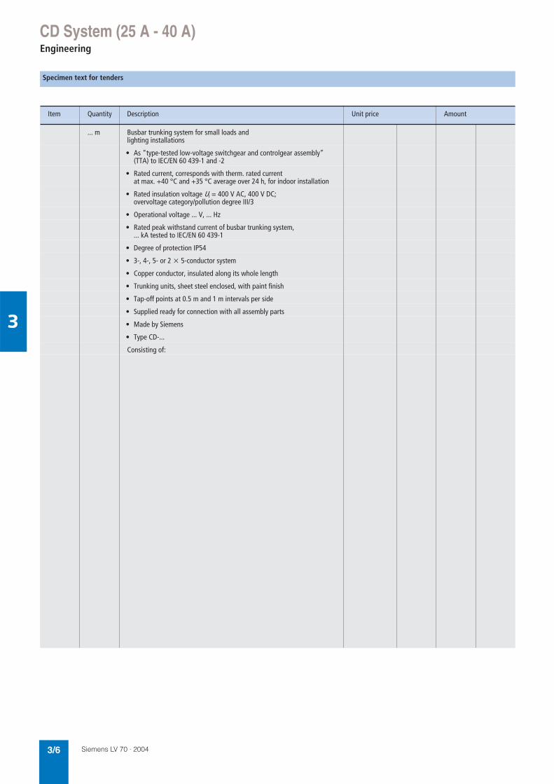
Specimen text for tenders
Item Quantity Description Unit price Amount
... m Busbar trunking system for small loads and lighting installations
• As “type-tested low-voltage switchgear and controlgear assembly” (TTA) to IEC/EN 60 439-1 and -2
• Rated current, corresponds with therm. rated current at max. +40 °C and +35 °C average over 24 h, for indoor installation
• Rated insulation voltage Ui = 400 V AC, 400 V DC; overvoltage category/pollution degree III/3
• Operational voltage ... V, ... Hz
• Rated peak withstand current of busbar trunking system,... kA tested to IEC/EN 60 439-1
• Degree of protection IP54
• 3-, 4-, 5- or 2 5-conductor system
• Copper conductor, insulated along its whole length
• Trunking units, sheet steel enclosed, with paint finish
• Tap-off points at 0.5 m and 1 m intervals per side
• Supplied ready for connection with all assembly parts
• Made by Siemens
• Type CD-...
Consisting of:

EngineeringCD System (25 A - 40 A)
Siemens LV 70 · 2004 3/7
3
Concentrated load Balanced load
Determining fixing intervals
The closed section of the CD system has a high degree of mechanical strength. The load diagrams show the maximum permissible loading in relation to the fixing interval (distance between suspension points).Deflection f of the busbar trunking unit should not be greater than 1/300 of the distance (L) between supports. F = balanced load.
Balanced load Concentrated load
L
f
L
F
Concentrated and balanced loads in relation to suspension point interval
Pendant fixing using CD-BA
4
6
8
10
12
14
16
18(kg)
2.00 2.50 3.00 (m)
= 1/300
Wei
ght o
f fitt
ed lo
ads
Fixing interval L
f/L
f/L
= 1/500
3 m
3 m
Underfloor mounting with CD-BUF
4
6
8
10
12
14
16
18(kg)
2.00 2.50 3.00 (m)
f/L = 1/500f/L = 1/300
Fixing interval L
Wei
ght o
f fitt
ed lo
ads
3 m
F 3 m

EngineeringCD System (25 A - 40 A)
Siemens LV 70 · 20043/8
3
The numbers, e.g. a, indicate the corresponding position of the luminaires in the table below.
Single lamp
= single lamp, non-compensated, cos ϕ ≈ 0.5
= single lamp, parallel-compensated, cos ϕ ≈ 0.9
= single lamp, alternately series-compensated, cos ϕ ≈ 0.1
Two lamps
= two lamps, non-compensated
= two lamps, twin-lamp circuit, cos ϕ ≈ 1
Three lamps
= three lamps, alternately series-compensated
= three lamps, non-compensated
Arrangement of luminaires
X X X
L1L2L3N
X X X
L1L2L3N
X X X
L1L2L3N
X X X
X
X
X X
X X
L1L2L3N
X X
X
X
X
X
X
L1L2L3N
X
X
X
X
X
X
L1L2L3N
X
X
X
L1L2L3N

Engineering
Siemens LV 70 · 2004 3/9
CD System (25 A - 40 A)
3
Connectable luminaires without consideration of voltage drop
Lamp voltage per luminaire(linear fluorescent lamp)
Connectable luminaires with protection by miniature circuit-breaker
at 16 A at 20 A at 25 A at 32 A
Arrange-mentof lumi-naires
Rated current with choke
Length of light fixture
Units/phase
Total length for connection to 3-phases
Units/phase
Total length for connection to 3-phases
Units/phase
Total length for connection to 3-phases
Units/phase
Total length for connection to 3-phases
A m, approx.
m, approx.
m, approx.
m, approx.
m, approx.
1 36 W1 58 WNon-compensatedsingle-phase
0.440.70
1.251.55
3320
12896
4225
163120
5232
202153
6640
248186
1 36 W1 58 WParallel-compensatedsingle-phase
0.250.40
1.251.55
3019
11791
3724
144115
4730
183144
5937
222173
1 36 W1 58 WAlternatelycompensatedsingle-phase
0.230.35
1.251.55
4832
187153
6040
234192
7550
292240
9664
360298
2 36 W 2 58 WNon-compensatedsingle-phase
0.881.40
1.251.55
1610
6248
2112
8157
2616
10176
4120
12493
2 36 W2 58 WTwin-lamp circuit,single-phase
0.460.71
1.251.55
2416
9376
3020
11796
3725
144120
4732
177149
3 36 W3 58 WAlternatelycompensatedthree-phase
0.230.35
1.251.55
4832
6251
6040
7864
7550
9780
9664
125103
3 36 W 3 58 WNon-compensatedthree-phase
0.440.70
1.251.55
3320
4232
4225
5440
5232
6751
6640
8664

Engineering
Siemens LV 70 · 20043/10
CD System (25 A - 40 A)
3
Lamp voltage per luminaire(linear fluorescent lamp)
Connectable luminaires with protection by gL fuses
at 16 A at 20 A at 25 A at 35 A
Arrange-mentof lumi-naires
Rated current with choke
Length ofof light fixture
Units/phase
Total length for connection to 3-phases
Units/phase
Total length for connection to 3-phases
Units/phase
Total length for connection to 3-phases
Units/phase
Total length for connection to 3-phases
A m, approx.
m, approx.
m, approx.
m, approx.
m, approx.
1 36 W1 58 WNon-compensatedsingle-phase
0.440.70
1.251.55
3320
12896
4225
163120
5232
202153
7244
280211
1 36 W1 58 WParallel-compensatedsingle-phase
0.250.40
1.251.55
3623
140110
4428
171134
6038
234182
9056
351268
1 36 W1 58 WAlternatelycompensatedsingle-phase
0.230.35
1.251.55
4832
187153
6040
234192
7550
292240
10570
409336
2 36 W 2 58 WNon-compensatedsingle-phase
0.881.40
1.251.55
1610
6248
2112
8157
2616
10176
3622
140105
2 36 W2 58 WTwin-lamp circuit,single-phase
0.460.71
1.251.55
2416
9376
3020
11796
3725
144120
5135
198168
3 36 W3 58 WAlternatelycompensatedthree-phase
0.230.35
1.251.55
4832
6251
6040
7864
7550
9780
10570
136112
3 36 W 3 58 WNon-compensatedthree-phase
0.440.70
1.251.55
3320
4232
4225
5440
5232
6751
7244
9364
EngineeringCD System (25 A - 40 A)
Siemens LV 70 · 2004 3/11
3
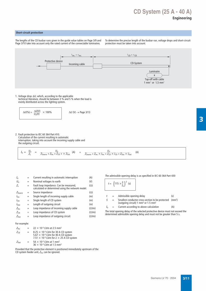
The lengths of the CD busbar runs given in the guide value tables on Page 3/9 and Page 3/10 take into account only the rated current of the connectable luminaires.
To determine the precise length of the busbar run, voltage drops and short-circuit protection must be taken into account.
For example:
Provided that the protective element is positioned immediately upstream of the CD system feeder unit, ZInc can be ignored.
The admissible opening delay is as specified in IEC 60 364 Part 430
The total opening delay of the selected protective device must not exceed the determined admissible opening delay and must not be greater than 5 s.
Short-circuit protection
Protective deviceIncoming cable CD-System
Luminairex
Tap-off with cable1 mm or 1,5 mm2 2
inc. inc.zl CD CDzl
1. Voltage drop U, which, according to the applicabletechnical literature, should lie between 3 % and 5 % when the load isevenly distributed across the lighting system.
∆U (V) → Page 3/13DU(%) = DU(V)Ue(V)
x 100%
2. Fault protection to IEC 60 364 Part 410.Calculation of the current resulting in automaticinterruption, taking into account the incoming supply cable andthe outgoing circuit.
Ia = UoZs
= UoZSource + ZInc + ZCD + ZOut
UoZSource + ZInc lInc + ZCD lCD + ZOut lOut
=(A) (A)
Ia = Current resulting in automatic interruption (A)Uo = Nominal voltages to earth (V)Zs = Fault loop impedance. Can be measured,
calculated or determined using the network model.(Ω)
ZSource = Source impedance (Ω)lInc = Single length of incoming supply cable (m)lCD = Single length of CD system (m)lOut = Length of outgoing circuit (m)ZInc = Loop impedance of incoming supply cable (Ω/m)ZCD = Loop impedance of CD system (Ω/m)ZOut = Loop impedance of outgoing circuit (Ω/m)
ZInc = 22 10-3 Ω/m at 2.5 mm2
ZCD = 8.25 10-3 Ω/m for 30 A CD system5.67 10-3 Ω/m for 40 A CD system7.51 10-3 Ω/m for 2 25 A CD system
ZOut = 54 10-3 Ω/m at 1 mm2
36 10-3 Ω/m at 1.5 mm2
t = Admissible opening delay (s)S = Smallest conductor cross-section to be protected
(outgoing circuit) 1 mm2 or 1.5 mm2(mm2)
Ia = Current according to above calculation (A)
t = S
Ia(s)(115 x ) 2

EngineeringCD System (25 A - 40 A)
Siemens LV 70 · 20043/12
3
A system can be protected against start circuit alone, by fitting low-voltage h.b.c. fuses (gL) into the incoming supply; the fuse size to be appropriate for the prospective short-circuit current at the point of installation.
Due to their high response threshold (1.3 – 1.6 times rated current) and their long rupturing times at small overcurrents, fuses are not suitable for overload protection.For protecting the CD busbar trunking system and its outgoing circuits, we recommend miniature circuit-breakers and motor-protective circuit-breakers.
Short-circuit protection
System Protective device per circuit
Icf = 25 kA
CD-130. NH00 32 gL
CD-140. NH00 40 gL
CD-225. NH00 25 gL
Notes Icf = Rated conditional short-circuit current of thebusbar trunking system and its outgoing circuits when protected by a fuse
Overcurrent protective devices for overload and short-circuit protection
System Protective device per circuit
Icc = 15 kA Icc = 20 kA Icc = 25 kA
CD-130. FAZ-3-B32 AZ-3-C32 PKZ 2/ZM-32-8
CD-140. FAZ-3-B40 AZ-3-C40 PKZ 2/ZM-40-8
CD-225. FAZ-3-B25 AZ-3-C25 PKZ 2/ZM-25-8
Notes Icc = Rated conditional short-circuit current of thebusbar trunking system and its outgoing circuits when protected by circuit-breakers

EngineeringCD System (25 A - 40 A)
Siemens LV 70 · 2004 3/13
3
(Load distribution factor a = 0.5 for lighting installations)Three-phase current (3 ~), alternating current (~)
Temperature characteristic of CD systems
For long busbar runs, it may be necessary to calculate the voltage drop.
Alternating current
Three-phase current
Factor “a” used in the equation for calculating the voltage drop is dependent on the load distribution.
Voltage drop at rated current
20
DU (V/100 m)
18
16
14
12
10
8
30 A (~
)
25 A (~)
40 A (~)30 A (3~)
25 A (3~)
40 A (3~)
6
4
20.4 0.5 0.6
cos v
0.7 0.8 0.9 1.0
-5
130
Rated current (%)
Ambient temperature °C(average over 24 hours)
120
110
100
90
80
70
+5 +15 +25 +35 +45 +55 +65
Voltage drop
∆U = Voltage drop (V)I = Load current (A)l = Length (m)a = Load distribution factorR = Ohmic resistance R20 (mΩ/m)X = Inductive reactance X20 (mΩ/m)cos ϕ = Power factor
Load distribution Factor a
Supply at AOne tap-off at B 1
Supply at ATap-off at B, C, D, E 0.5
Supply at ATap-off at C, D, E, F 0.25
DU = ax Ix 2lx (Rx cos v + Xx sin v)x 10–3 (V)
DU = ax 3x Ix lx (Rx cos v + Xx sin v)x 10–3 (V)
BA
EA
DCB
FA
EDCB

Selection and ordering dataTrunking Units, Feeder Units
Siemens LV 70 · 20043/14
CD System (25 A - 40 A)
3
Length Tap-off points Tap-off pointspacing
m m
Trunking units• Sheet steel housing• Similar to RAL 9002 (white-grey)• Tap-off points can be coded
3 3 Single conductor run
1
3 3 Single conductor run
1
2 2 Single conductor run
1
3 3 Single conductor run
1
3 5 Single conductor run
0.5
2 3 Double conductor run
0.5, alternating
3 5 Double conductor run
0.5, alternating
3 10 Double conductor run
0.5
Feeder units
• Insulated housing• Cable entry from 3 sides• M25 or M32 plastic cable gland with strain relief,
(not included as standard)• Terminals for 2.5 to 10 mm2 cables
Entry feeder units• Including CD-EF end flange
Single conductor run
Double conductor run
End feeder units• Including CD-EF end flange
Single conductor run
Double conductor run
L1N
PE
L2L1N
PE
L2L1
L3
N
PE
L2L1
L3
N
PE
L2L1
L3
N
PE
L2L1
L3
N
PE
L2L1
L3
N
PE
L2L1
L3
N
PE

Selection and ordering dataTrunking Units, Feeder Units
Siemens LV 70 · 2004 3/15
CD System (25 A - 40 A)
3
Rated current Ie30 A
Rated current Ie2 x 25 A
Rated current Ie40 A
Type PriceSeePrice List
Type PriceSeePrice List
Type PriceSeePrice List
Article no. Article no. Article no. PS*
CD-K-1302-3211151
– CD-K-1402-3211156
1 unit
CD-K-1303-3211152
– CD-K-1403-3211157
CD-K-1304-2211153
– CD-K-1404-2211158
CD-K-1304-3211154
– CD-K-1404-3211159
CD-K-1304-3-05211155
– CD-K-1404-3-05211160
– CD-K-2254-2211161
–
– CD-K-2254-3211162
–
– CD-K-2254-3-05211163
–
CD-K-1304-EA211164
– CD-K-1404-EA211166
1 unit
– CD-K-2254-EA211168
–
CD-K-1304-EE211165
– CD-K-1404-EE211167
– CD-K-2254-EE211169
–
* This quantity or a multiple thereof can be ordered.

Selection and ordering dataTap-Off Plugs
Siemens LV 70 · 20043/16
CD System (25 A - 40 A)
3
Type PriceSeePrice List
Rated current Article no. PS*IeA
Tap-off plugs3-pole• Can be changed over to L1 or L2 or L3 with N and PE• Without fuses• Halogen-free cable to IEC 60 754-1 and
flame-retardant to IEC 60 332-1
With 0.8 m cable, 3 x 1 mm² 10 CD-K-A3O-1211187
1 unit
With 3 m cable, 3 x 1 mm² 10 CD-K-A3O-3211188
With 4 m cable, 3 x 1 mm² 10 CD-K-A3O-4211189
With 5 m cable, 3 x 1 mm² 10 CD-K-A3O-5211190
With 8 m cable, 3 x 1 mm² 10 CD-K-A3O-8211191
5-pole• L1, L2, L3, N and PE• Without fuses• Halogen-free cable to IEC 60 754-1 and
flame-retardant to IEC 60 332-1
With 0.8 m cable, 5 x 1 mm² 10 CD-K-A5O-1211192
1 unit
With 3 m cable, 5 x 1 mm² 10 CD-K-A5O-3211193
With 5 m cable, 5 x 1 mm² 10 CD-K-A5O-5211194
With 8 m cable, 5 x 1 mm² 10 CD-K-A5O-8211195
3-pole• Can be changed over to L1 or L2 or L3 with N and PE• For one 8.5 mmx 31.5 mm cylinder fuse,
type gG (IEC) or gL (VDE) (fast)• Halogen-free cable to IEC 60 754-1 and
flame-retardant to IEC 60 332-1
With 0.8 m cable, 3 x 1.5 mm² 16 CD-K-A3M-1211198
1 unit
With 3 m cable, 3 x 1.5 mm² 16 CD-K-A3M-3211199
1 unit
L3
L1L2
N
L3
L1L2
N
N
L2L1
L3
* This quantity or a multiple thereof can be ordered.

Selection and ordering dataTap-Off Plugs
Siemens LV 70 · 2004 3/17
CD System (25 A - 40 A)
3
Type PriceSeePrice List
Rated current Article no. PS*IeA
Tap-off plugs
3-pole• Can be changed over to L1 or L2 or L3 with N and PE• Without fuses
With plastic M20 cable grommetConnection via 2.5 mm² terminal
16 CD-K-A3O-0211196
1 unit
5-pole• L1, L2, L3, N and PE• Without fuses
With plastic M20 cable grommetConnection via 2.5 mm² terminal
16 CD-K-A5O-0211200
1 unit
3-pole• Can be changed over to L1 or L2 or L3 with N and PE• For one 8.5 mm x 31.5 mm cylinder fuse,
type gG (IEC) or gL (VDE) (fast)
With plastic M20 cable grommetConnection via 2.5 mm² terminal
16 CD-K-A3M-0211197
1 unit
5-pole• L1, L2, L3, N and PE• For three 8.5 mm x 31.5 mm cylinder fuses,
type gG (IEC) or gL (VDE) (fast)
With plastic M20 cable grommetConnection via 2.5 mm² terminal
16 CD-K-A5M-0211201
1 unit
N
L2L1
L3
* This quantity or a multiple thereof can be ordered.

Selection and ordering dataAccessories
Siemens LV 70 · 20043/18
CD System (25 A - 40 A)
3
Type PriceSeePrice List
Rated current Article no. PS*IeA
AccessoriesCylinder fuse• For CD-K-A.M-. tap-off plugs,
8.5 mm x 31.5 mm, with spring indicator, type gG (IEC), gL (VDE) (fast)
2 CD-ZS-2044891
10 units
4 CD-ZS-4044892
6 CD-ZS-6044893
8 CD-ZS-8044894
10 CD-ZS-10044895
12 CD-ZS-12044896
16 CD-ZS-16044897
Type PriceSeePrice List
Article no. PS*
AccessoriesCoding set
CD-K1211202
10 units
CD-K2211203
CD-K3211204
* This quantity or a multiple thereof can be ordered.

Selection and ordering dataAccessories
Siemens LV 70 · 2004 3/19
CD System (25 A - 40 A)
3
Type PriceSeePrice List
Article no. PS*
AccessoriesEnd flange CD-EF
0521241 unit
Fixing bracket• With paint finish• For mounting trunking units and luminaires
CD-B052134
12 units
Threaded/centring plate12 mm x 31.5 mm, M6• For CD-B fixing bracket
CD-GP088779
50 units
Suspension hook• For suspension by cable or chain in conjunction
with CD-B fixing bracket
CD-H086012
10 units
Suspension bracket• For suspension by cable or chain
(also for increased mechanical rigidity at the connecting points)
CD-BA025377
1 unit
Clip-type fixing bracket• For mounting trunking units and luminaires (balanced load)
CD-BC203519
12 units
Cable clip• For securing cables alongside trunking units
CD-CL203520
10 units
Fixing bracket • For underfloor mounting
CD-BUF272546
12 unit
* This quantity or a multiple thereof can be ordered.

Technical Data
Siemens LV 70 · 20043/20
CD System (25 A - 40 A)
3
Terminal capacity
CD-K-1302 CD-K-1303 CD-K-1304 CD-K-2254
ConductorsRated insulation voltage Ui V AC/DC 400/400 400/400 400/400 400/400Overvoltage category/pollution degree
III/3 III/3 III/3 III/3
Rated operational voltage Ue V AC 400 400 400 400Frequency Hz 50 – 60 50 – 60 50 – 60 50 – 60Rated current Ie therm. rated current at max. 40 °C and35 °C average over 24 hours
A 30 30 30 2 × 25
Impedance of conductors at 50 Hzand 20 °C busbar temperature
Resistance R20 mΩ/m 5.79 5.79 5.79 4.56Reactance X20 mΩ/m 0.26 0.26 0.26 0.15Impedance Z20 mΩ/m 5.80 5.80 5.80 4.56
Impedance of conductors under fault conditionsAC resistance RF mΩ/m 8.24 8.24 8.24 7.50Reactance XF mΩ/m 0.44 0.44 0.44 0.32Impedance ZF mΩ/m 8.25 8.25 8.25 7.51
“Null” impedance tested to IEC 60 909, VDE 0102 Resistance R0 Phase to N mΩ/m 24.24 24.24 24.24 18.59Reactance X0 Phase to N mΩ/m 1.77 1.77 1.77 0.82Impedance Z0 Phase to N mΩ/m 24.30 24.30 24.30 18.61Resistance R0 Phase to PE mΩ/m 12.00 12.00 12.00 13.49Reactance X0 Phase to PE mΩ/m 1.80 1.80 1.80 0.82Impedance Z0 Phase to PE mΩ/m 12.13 12.13 12.13 13.52
Short-circuit ratingRated peak withstand current Ipk kA 2.4 2.4 2.4 3.0Rated short-time withstand current Icw (t = 1 s) kA 0.56 0.56 0.56 0.69Rated short-time withstand current Icw (t = 0.1 s) kA 1.6 1.6 1.6 2.0Number of active conductors 2 3 4 2 × 4Conductor cross-section
L1, L2, L3 mm2 3.2 3.2 3.2 4.0N mm2 3.2 3.2 3.2 4.0PE (housing) Cu mm2 11 11 11 11
Conductor material Cu Cu Cu CuCombustive energy kWh/m 0.1 0.15 0.201 0.48Max. therm. load, I2t value A2s × 103 310 310 310 470Fixing intervals at normal mechanical load
m 3 3 3 3
Tap-off plugsTap-off point Offset every 0.5 m, 1 m or 0.5 m on each side; max. 16 ATap-off plug 3- and 5-pole; with or without permanently attached cable; with or without fuse
holders for 8.5 mm × 31.5 mm; type gG (IEC) and type gL (VDE) fast cylinder fuses.All tap-off plugs are of utilization category AC-20B to IEC/EN 60 947-3.The PE operates as an early-make contact during connection, and as alate-break contact during removal of the tap-off plug.
Designation Type L1, L2, L3 N PEMin.mm2
Max. mm2
Min.mm2
Max. mm2
Min.mm2
Max. mm2
Entry feeder unit CD-K-...-EA 2.5 6 (f)10 (st, so)
2.5 6 (f)10 (st, so)
2.5 6 (f)10 (st, so)
End feeder unit CD-K-...-EE 2.5 6 (f)10 (st, so)
2.5 6 (f)10 (st, so)
2.5 6 (f)10 (st, so)
Notes so = solid, st = stranded, f = flexible with ferrule

Technical Data
Siemens LV 70 · 2004 3/21
CD System (25 A - 40 A)
3
CD-K-1402 CD-K-1403 CD-K-1404 General technical data
400/400 400/400 400/400 Standards IEC/EN 60 439-1 and -2
Climatic proofing Damp heat, constant, to IEC 60 068-2-78Damp heat, cyclical, to IEC 60 068-2-30
Ambient temperature Min./Max. °C−5/+40
Degree of protection IP54, IEC/EN 60 529
Mounting position Edgewise; tap-off points at the side
Weight a Annex
Dimensions a Page 3/22Material
Trunking units Galvanized, painted sheet steel
Busbars Tinned and insulated round-section copper wire
III/3 III/3 III/3
400 400 40050 – 60 50 – 60 50 – 6040 40 40
3.55 3.55 3.550.40 0.40 0.403.57 3.57 3.57
5.61 5.61 5.610.80 0.80 0.805.67 5.67 5.67
14.85 14.85 14.850.99 0.99 0.9914.88 14.88 14.889.87 9.87 9.871.02 1.02 1.029.92 9.92 9.92
3.6 3.6 3.60.85 0.85 0.852.4 2.4 2.42 3 4
5.0 5.0 5.05.0 5.0 5.011 11 11Cu Cu Cu0.12 0.18 0.24720 720 7203 3 3

Dimension drawingsTrunking Units, Feeder Units, Tap-Off Plugs
Siemens LV 70 · 20043/22
CD System (25 A - 40 A)
3
Trunking units
CD-K-1302-3CD-K-1303-3CD-K-1304-2CD-K-1304-3
CD-K-2254-2CD-K-2254-3
CD-K-1402-3CD-K-1403-3CD-K-1404-2CD-K-1404-3
Feeder units
CD-K-1304-EECD-K-1404-EECD-K-2254-EE
For M25, M32
CD-K-1304-EACD-K-1404-EACD-K-2254-EA
For M25, M32
Tap-off plugs
CD-K-A3O-0CD-K-A3M-0CD-K-A5O-0CD-K-A5M-0
CD-K-A3M-1CD-K-A3M-3
CD-K-A3O-1CD-K-A3O-3CD-K-A3O-4CD-K-A3O-5CD-K-A3O-8
CD-K-A5O-1CD-K-A5O-3CD-K-A5O-5CD-K-A5O-8
2000/3000
500 1000
500 500
42
30Lengthm
Number oftap-off points
2 2 or 33 3, 5 or 10
99 130
8566
130 99
M25, M32
L2
N
L3
L1 42 59
48
59
189
L2
N
L3
L1
5058
58 59

Dimension drawingsAccessories
Siemens LV 70 · 2004 3/23
CD System (25 A - 40 A)
3
Fixing brackets
CD-B CD-BC
Suspension bracket
CD-BA
Bracket underfloor mounting
CD-BUF
End flange
CD-EF
Cable clip
CD-CL
Coding set CD-K1 (K2, K3)
CD-K1 CD-K2 CD-K3
20
20
1092
35
26
74 12
5.3
6.4
25
17
47
32
42.3
200
76
7 x 9
34
58 37
42
22 30
36
30
20
10
9.7
26.7
7.3
18.2
18.2
36.4
34
8.5
9.7
26.7

Notes
Siemens LV 70 · 20043/24
CD System (25 A - 40 A)
3