CCO® System€¦ · 4.1.1- Stage 1: Leveling and Aligning 4.1.2- Stage 2: Working Stage 4.1.3-...
70
Antonino G. Secchi DMD, MS Principles and Technique Complete Clinical Orthodontics ® CCO® System
Transcript of CCO® System€¦ · 4.1.1- Stage 1: Leveling and Aligning 4.1.2- Stage 2: Working Stage 4.1.3-...
0280-MM-120-057-04 Rev. 04
© 2017 Dentsply SironaAll Rights Reserved.
800.645.5530www.dentsplysirona.com/orthodontics
Antonino G. Secchi DMD, MS
Principles and Technique
www.ccosystem.com
Complete Clinical Orthodontics®
CCO® System
Academy
*+D807120057041/$$7201710A*

Complete Clinical Orthodontics
CCO SystemPrinciples and TechniqueFifth Edition, 2017
© Antonino G. Secchi, DMD, MS

1
I would like to dedicate this work to my family,specifically to my wife Maria and my five children,
Sofia, Ella, Bella, Leonardo and Camillafor their unconditional love and support.
Table of Contents
1 - Introduction
2 - Self-ligation and the In-Ovation bracket system
2.1- The CCO Rx. The ultimate prescription for active SLB.
3 - Optimal Bracket Placement
4 - Treatment Mechanics
4.1- Stages of Treatment Mechanics
4.1.1- Stage 1: Leveling and Aligning
4.1.2- Stage 2: Working Stage
4.1.3- Stage 3: Finishing Stage
4.2 - Distal Movement of Maxillary Molars
5 - Clinical Cases
CCO® System: Principles and Technique / ccosystem.com 32
Treatment mechanics has always been of tremendous
interest for all practicing orthodontists. Since the beginning
of our specialty, we have looked for the best, fastest, more
consistent and easiest way to achieve the orthodontic
correction for our patients. This continuous quest has
allowed emerging technologies to integrate, although
slowly sometimes, with our everyday practice until they
become a routine. Thus, as a consequence, new materials,
improvement in design of appliances and innovative ideas
repeatedly transform the way we practice. It is important
for the contemporary orthodontist to be knowledgeable of
current changes, so to take the best of them.
Today, after the first decade of the 21st century has already
passed, orthodontic fixed appliances have experienced an
interesting blend between technologies that have been
around for decades, such as the Straight Wire Appliance
(SWA), self-ligation and low deflection thermal-activated
archwires. This integration, in my opinion, represents an
improvement that, when correctly applied, facilitates the
practice of orthodontics.
In this manual the reader will find the author’s interpre-
tation of how the SWA integrates with self-ligation and how
this appliance, with the combination of a specific archwire
sequence, can help the orthodontist to correct different
types of malocclusions in the adult dentition. Relevant
characteristics of active self-ligating appliances, a modified
prescription (CCO Rx), along with a specific wire sequence
for different orthodontic scenarios, are among the areas
covered.
To facilitate the understanding of the mechanics utilized in
different situations, 10 cases “step by step” were included.
Type of appliance, wire sequence, and any auxiliary used
are specified. I selected these cases because I think they
depict “everyday” problems we face in our practices.
1. Introduction
In the last few years self-ligating appliances have become
very popular. A great deal of discussion has arisen around
the friction these systems are able to generate. Self-ligating
brackets have been classified as “Active” or “Passive”
depending on the behavior of the gate or clip on the
archwire.
Active self-ligating brackets (Fig. 2-1) have a clip with
a springing effect that exerts pressure on the archwire
pushing it onto the base of the bracket’s slot. This pressure
is based on the archwire size and or bracket/archwire
configuration. On the other hand, passive self-ligating
brackets (Fig. 2-2) have a gate that passively opens and
closes without exerting pressure on the archwire. Passive
self-ligating brackets have also been described as tubes.
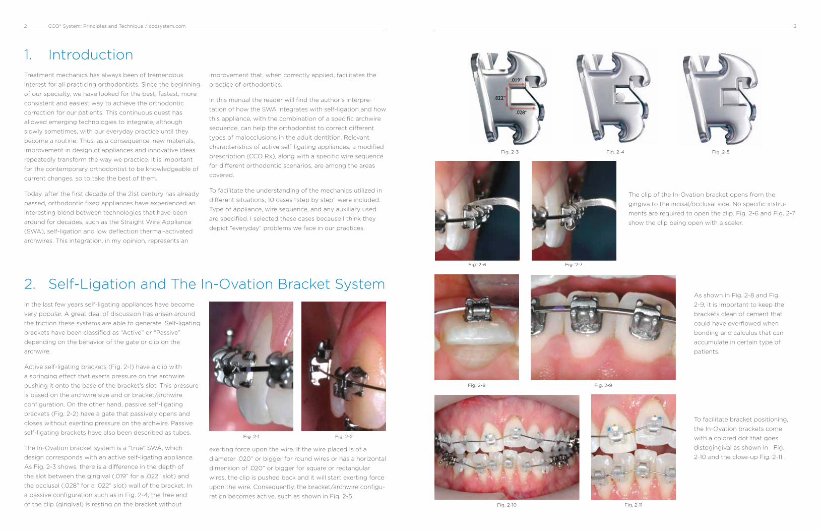
The In-Ovation bracket system is a “true” SWA, which
design corresponds with an active self-ligating appliance.
As Fig. 2-3 shows, there is a difference in the depth of
the slot between the gingival (.019” for a .022” slot) and
the occlusal (.028” for a .022” slot) wall of the bracket. In
a passive configuration such as in Fig. 2-4, the free end
of the clip (gingival) is resting on the bracket without
exerting force upon the wire. If the wire placed is of a
diameter .020” or bigger for round wires or has a horizontal
dimension of .020” or bigger for square or rectangular
wires, the clip is pushed back and it will start exerting force
upon the wire. Consequently, the bracket/archwire configu-
ration becomes active, such as shown in Fig. 2-5
2. Self-Ligation and The In-Ovation Bracket System
Fig. 2-1 Fig. 2-2
Fig. 2-3 Fig. 2-4 Fig. 2-5
The clip of the In-Ovation bracket opens from the
gingiva to the incisal/occlusal side. No specific instru-
ments are required to open the clip. Fig. 2-6 and Fig. 2-7
show the clip being open with a scaler.
Fig. 2-6 Fig. 2-7
As shown in Fig. 2-8 and Fig.
2-9, it is important to keep the
brackets clean of cement that
could have overflowed when
bonding and calculus that can
accumulate in certain type of
patients.
Fig. 2-8 Fig. 2-9
To facilitate bracket positioning,
the In-Ovation brackets come
with a colored dot that goes
distogingival as shown in Fig.
2-10 and the close-up Fig. 2-11.
Fig. 2-11Fig. 2-10
CCO® System: Principles and Technique / ccosystem.com 54
Fig. 2-12 shows an In-Ovation ‘R’ bracket with clip closed (a), the clip being opened with a commonly available scaler (b),
and the clip completely opened (c).
Fig. 2-14 a, b and c show a sequence of bracket/wire engagement utilizing dental floss as an aid to engage the wire into
the slot of the self-ligating bracket in a situation of severe crowding. The wire must be completely engaged into the slot of
the bracket for the clip to be able to close.
Fig. 2-13 shows an In-Ovation ‘R’ bracket with clip opened and a round wire being placed into the slot with a ligature
director (a), the clip being closed with a finger (b), and the clip completely closed (c).
Fig. 2-12a
Fig. 2-13a
Fig. 2-14a
Fig. 2-12b
Fig. 2-13b
Fig. 2-14b
Fig. 2-12c
Fig. 2-13c
Fig. 2-14c
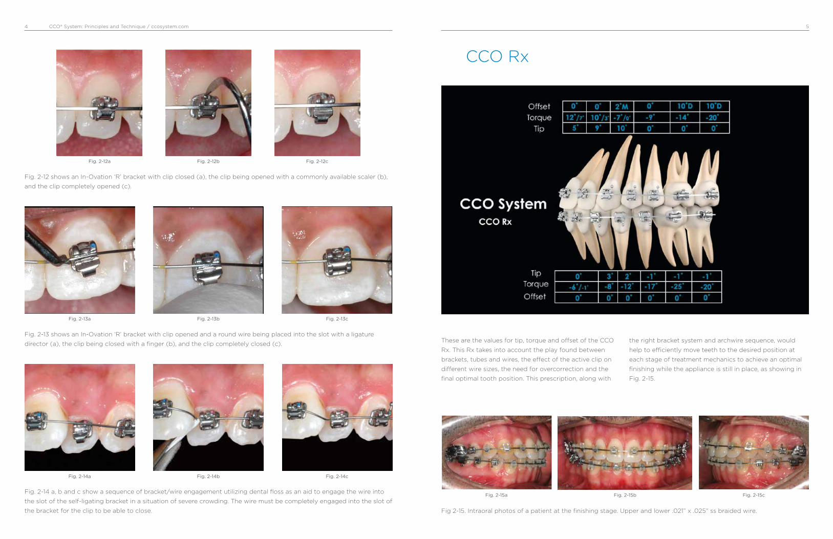
These are the values for tip, torque and offset of the CCO
Rx. This Rx takes into account the play found between
brackets, tubes and wires, the effect of the active clip on
different wire sizes, the need for overcorrection and the
final optimal tooth position. This prescription, along with
the right bracket system and archwire sequence, would
help to efficiently move teeth to the desired position at
each stage of treatment mechanics to achieve an optimal
finishing while the appliance is still in place, as showing in
Fig. 2-15.
CCO Rx
Fig 2-15. Intraoral photos of a patient at the finishing stage. Upper and lower .021” x .025” ss braided wire.
Fig. 2-15a Fig. 2-15cFig. 2-15b

CCO® System: Principles and Technique / ccosystem.com 76
CCO Rx – Rationale behind a new Rx.
Larry Andrews introduced the Straight Wire Appliance
(SWA) in 1970. This was the first orthodontic appliance with
all three dimensions for tooth position built into the bracket.
Each bracket was designed to be tooth specific. Tip,
torque and o�set for each tooth were selected based on
the measurements that Andrews obtained after examining
120 “ideal” sets of models from individuals who never had
orthodontic treatment. The Andrews Standard Rx was born.
Andrews then introduced a series of additional brackets
with di�erent degrees of overcorrection to account for
undesired tooth movement when sliding teeth in extraction
cases. He called this series of overcorrected brackets,
“Translation Brackets”.
In the early 80s’, Ron Roth combined some of the Andrews
Standard Rx values with some of the values found in the
Translation Bracket Rx to come out with the Roth setup.
Filling the slot with a large stainless steel archwire to
express the Rx was one of the premises of the Roth system.
The Roth Rx was born.
In the early 90s’ McLaughlin, Bennett and Trevisi modified
the SWA Rx based on the fact that most orthodontists
would finish cases with a .019x.025 ss wire, which on a
.022 slot could have up to 12° of play. Among others,
they increased buccal crown torque for maxillary incisors,
reduced lingual crown torque for mandibular molars, and
increased lingual crown torque for mandibular incisors. The
MBT Rx was born.
Over the last decade, I have used di�erent “versions” of the
SWA, studying its concept and development and collecting
personal experiences as well as experiences from many
clinicians. I have used di�erent Self-Ligating Brackets
(SLBs), studied the theory behind them, used them in my
own patients (today 100% of my practice is Active SLB) and
researched them in-vitro. After all, I came to the conclusion
that once all the “dust” produced by unsupported claims
favoring one specific passive SLB is cleaned, active SLBs
have a lot to o�er to facilitate and therefore improve the
delivery of our treatment. However, based on the particular
interaction between bracket and archwires due to the active
clip, a “fine-tuning” of the Rx needed to be done, and then
the CCO Rx was developed.
The CCO Rx
The CCO Rx was developed to take full advantage of the
bracket/archwire interaction when using an active clip and
to achieve optimal tooth position at the end of treatment.
Rotational Control
The springing capability together with the quite long
mesial-distal span of the active clip in the In-Ovation
brackets facilitate the correction of all rotations within the
stage of leveling and aligning. Also, the active clip favors
complete engagement of the wire into the slot. This means
that if the wire if not fully engaged, the clip will not close.
This avoids leaving small rotations uncorrected as the wire
sequence progresses. Therefore, the CCO Rx removed some
of the overcorrection of the o�set found in previous Rxs.
Full Torque Expression
Thanks to the active clip of the In-Ovation brackets, full
torque expression is achieved on a .019 x .025 ss archwire.
The springing clip pushes the wire into the slot. Dr.
Nobrega’s research shows that on the In-Ovation brackets
a .019 x .025 ss wire can express the same amount of
torque than a .021 x .025 ss wire. Therefore, some of the
overcorrections of torque implemented in previous Rxs, to
overcome the play between the bracket and a .019 x .025
ss, do not apply when using the In-Ovation bracket, and
therefore the CCO Rx removed them.
Molars Control
It is the interaction between the bracket and the wire that
will transfer the values of tip, torque and o�set to the
teeth. Tubes are passive attachments. Tubes are not able
to transfer the values they have, specifically torque, even if
large wires are used. Trouble correcting the curve of Wilson
of maxillary molars and excessive lingual crown torque of
mandibular molars are some of the problems commonly
reported by many orthodontists. Therefore, the CCO Rx has
a specific overcorrection for the maxillary and mandibular
first and second molars to achieve proper molar control on
a .019 x .025 ss archwire.
Incisors Control
Achieving optimal torque of the maxillary and mandibular
incisors is very important for both esthetics and function. It
a�ects lip support and consequently facial esthetics as well
as anterior coupling of the incisors and therefore anterior
guidance. For the maxillary incisors to achieve optimal
torque is sometimes di¡cult due to the large amount of
bone the roots must go through, specifically in extraction
cases as well as Class II div II cases.
The inclination of the mandibular incisors is critical for both
function and stability. Their position should be upright onto
the alveolar bone. Class III camouflage, Class II mechanics,
and deep curve of Spee are specifically challenging with
regard to the upright position of mandibular incisors. The
CCO Rx combines proven values of torque for maxillary
incisors that can be fully expressed, thanks to the active
clip, with a lightly overcorrection for the mandibular
incisors to achieve optimal control in all kinds of clinical
situations. The CCO Rx is conveniently and progressively
expressed throughout the stages of treatment mechanics
by using specific archwires at each stage. The ultimate goal
is to achieve optimal tooth position at the end of treatment,
even before the appliance is removed.
CCO Rx Highlights
The CCO Rx works as one system from second molar to
second molar. The following are some of the highlighted
changes that were introduced:
U1/U2: 12°/10° of torque have been selected. These values
have been proven time after time to be optimal if full
expression of torque is achieved. Thanks to the active clip,
full expression can be achieved on a .019 x .025 ss wire. It is
NOT necessary to increase and/or overcorrect these values.
U3: 10° of tip has been selected as the best of both worlds.
The increased mesial crown tip found in some Rxs (13°)
has shown undesired distal tip of the U3 root frequently
seen in x-rays. However, an upright U3 (8° or less) could
compromise proper coupling with the L3 and could also
leave spaces in the upper arch that when closed could
prevent a proper Class I relationship.
U4/U5: Same values of torque, tip and o�set for both; U4
and U5 make them interchangeable and facilitate bracket
inventory.
U6/U7: -14°/-20° of torque. Increased lingual crown torque,
specifically for the second molar, facilitates the correction
of the curve of Wilson and therefore arch coordination,
minimizing the need to add extra torque through a bend in
the wire or by using auxiliaries such as palatal bars.

CCO® System: Principles and Technique / ccosystem.com 98
Molar tubes are essentially passive attachments. They have
four rigid walls that make a tunnel to what the archwire
goes through. The passivity of the molar tubes has very
important clinical implications that we should understand in
order to take full advantage of our appliances.
Since molar tubes are generally wide in design (4 mm or
more), they can control very well rotations and tip. Rotations
and tip correction begin early in treatment with round wires.
The problem with current tubes is the lack of torque they are
able to express due to their passivity. It is quite impressive
to see how much play large rectangular archwires have
when coupling with molar tubes. Fig. 2-16 and 2-17 show
a SEM picture of a .019” x .025” and a .021” x .025” ss wire
respectively, coupled with a molar tube. In both pictures we
can see the amount of space left between the wire and the
buccal wall of the tube. In this regard, I challenge the readers
to go back to their o¡ces and grab any molar tube they are
using and couple it with the biggest archwire they have (you
can go up to a .021” x .028” ss). The amount of buccolingual
play you will find, I know, will be rather unexpected.
When optimal occlusion is the goal, we need to understand
that there aren’t too many di�erent ways we can position
teeth to achieve an optimal intercuspation (Fig. 2-18). This
concept of optimal tooth position is important to under-
stand when using fully adjusted appliances because we rely
on them to transfer the information they have to the teeth
in order to obtain the desired tooth position. This is specifi-
cally relevant when moving molars to their optimal position
because it is in this area where the fully adjusted appliances
we use are not able to transfer the information they have to
the molars and therefore optimal tooth position is di¡cult
to achieve.
L1/L2: -6°, 0°, 0° of torque, tip and o�set have been
selected. A small lingual crown torque overcorrection has
been shown to help keep the incisors in an upright position
when leveling and aligning and through Class II correction.
0° tip and 0°o�set makes all 4 incisor brackets to be inter-
changeable, facilitating bracket inventory.
L3: -8° of torque: In many cases, where the width of the
maxillary and mandibular arches is normal, an excessive
lingual crown torque (-11°), found in some Rxs, makes
di¡cult the coupling with the U3. Therefore, the torque for
the lower canines was changed to -8°.
L4/L5: 2°/-1° of tip. Although this small di�erence of tip
between the L4 and L5 will not be seen in non-extraction
cases, it is in agreement with di�erences in anchorage
requirement between extracting L4 or L5.
L6/L7: -25°/-20° of torque. These values have been
selected to facilitate upright L6/L7, preventing them from
rolling lingually.
TOOTH TORQUE TIP OFFSET
L1 • 2 -6 0 0
L1 • 2 High Torque -1 0 0
L3 Hook* -8 3 0
L4 -12 2 0
L4 Hook* -12 2 0
L5 -17 -1 0
L5 Hook* -17 -1 0
L6 Hook* -25 -1 0
L7 Hook* -20 -1 0
TOOTH TORQUE TIP OFFSET
U1 12 5 0
U1 Low Torque 7 5 0
U2 10 9 0
U2 Low Torque 3 9 0
U3 Hook* -7 10 2M
U3 Low Torque Hook* 0 10 2M
U4 • 5 -9 0 0
U4 • 5 Hook* -9 0 0
U6 Hook* -14 0 10D
U7 Hook* -20 0 10D
The CCO System RxMaxillary Arch Mandibular Arch
*All hooks are placed disto-gingivally. Note: Values of torque, tip and o�set refers to the crowns. Positive values of torque and tip mean buccal while negative mean lingual. O�set values are indicated as M (mesial) or D (distal).
Molar Tubes
Fig. 2-17SEM 30x picture of a molar tube coupled with a .021” x .025” ss wire.
Fig. 2-18
Fig. 2-16 SEM 30x picture of a molar tube coupled with a .019” x .025” ss wire.
CCO® System: Principles and Technique / ccosystem.com 1110
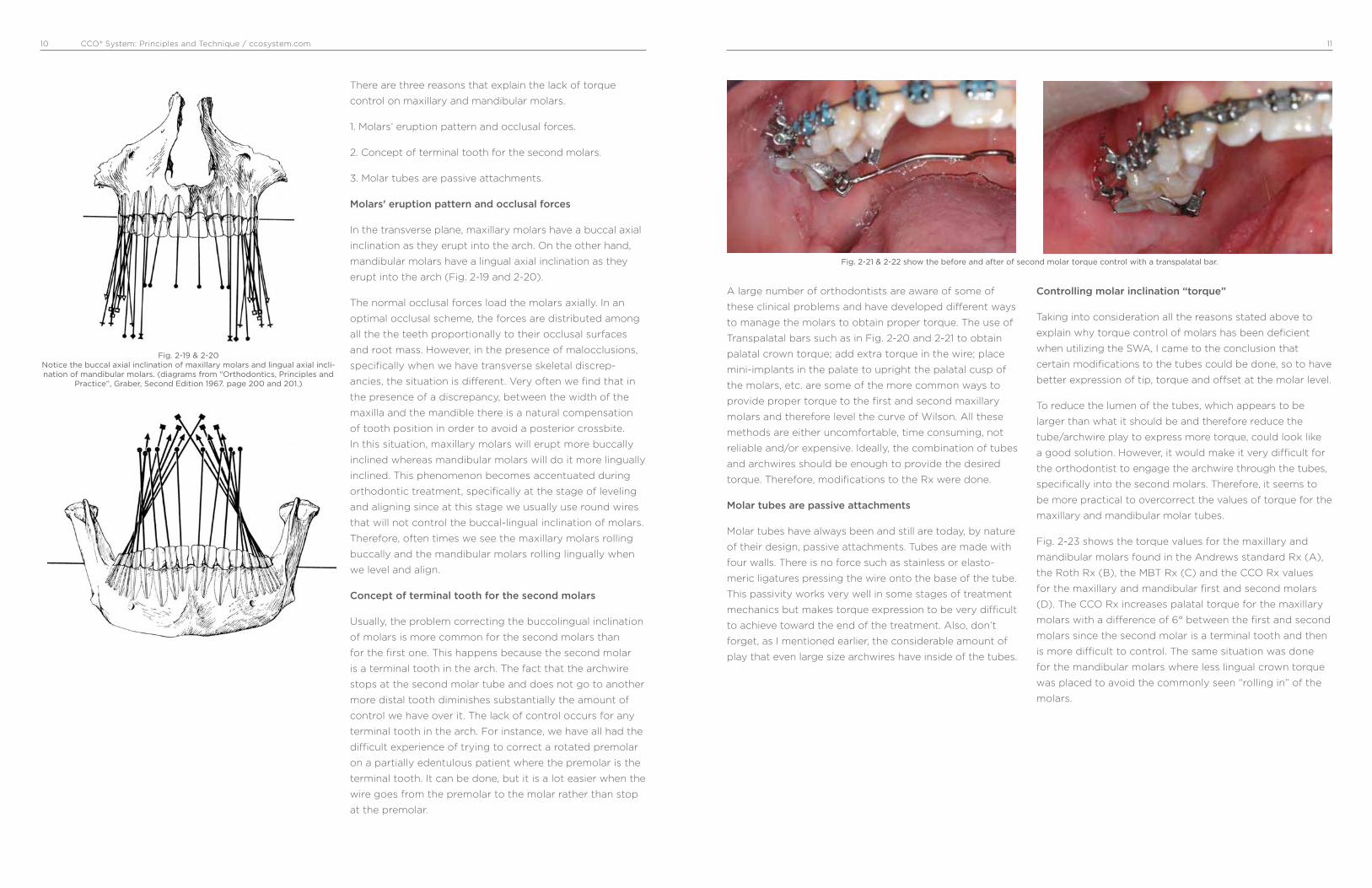
There are three reasons that explain the lack of torque
control on maxillary and mandibular molars.
1. Molars’ eruption pattern and occlusal forces.
2. Concept of terminal tooth for the second molars.
3. Molar tubes are passive attachments.
Molars’ eruption pattern and occlusal forces
In the transverse plane, maxillary molars have a buccal axial
inclination as they erupt into the arch. On the other hand,
mandibular molars have a lingual axial inclination as they
erupt into the arch (Fig. 2-19 and 2-20).
The normal occlusal forces load the molars axially. In an
optimal occlusal scheme, the forces are distributed among
all the the teeth proportionally to their occlusal surfaces
and root mass. However, in the presence of malocclusions,
specifically when we have transverse skeletal discrep-
ancies, the situation is different. Very often we find that in
the presence of a discrepancy, between the width of the
maxilla and the mandible there is a natural compensation
of tooth position in order to avoid a posterior crossbite.
In this situation, maxillary molars will erupt more buccally
inclined whereas mandibular molars will do it more lingually
inclined. This phenomenon becomes accentuated during
orthodontic treatment, specifically at the stage of leveling
and aligning since at this stage we usually use round wires
that will not control the buccal-lingual inclination of molars.
Therefore, often times we see the maxillary molars rolling
buccally and the mandibular molars rolling lingually when
we level and align.
Concept of terminal tooth for the second molars
Usually, the problem correcting the buccolingual inclination
of molars is more common for the second molars than
for the first one. This happens because the second molar
is a terminal tooth in the arch. The fact that the archwire
stops at the second molar tube and does not go to another
more distal tooth diminishes substantially the amount of
control we have over it. The lack of control occurs for any
terminal tooth in the arch. For instance, we have all had the
difficult experience of trying to correct a rotated premolar
on a partially edentulous patient where the premolar is the
terminal tooth. It can be done, but it is a lot easier when the
wire goes from the premolar to the molar rather than stop
at the premolar.
A large number of orthodontists are aware of some of
these clinical problems and have developed different ways
to manage the molars to obtain proper torque. The use of
Transpalatal bars such as in Fig. 2-20 and 2-21 to obtain
palatal crown torque; add extra torque in the wire; place
mini-implants in the palate to upright the palatal cusp of
the molars, etc. are some of the more common ways to
provide proper torque to the first and second maxillary
molars and therefore level the curve of Wilson. All these
methods are either uncomfortable, time consuming, not
reliable and/or expensive. Ideally, the combination of tubes
and archwires should be enough to provide the desired
torque. Therefore, modifications to the Rx were done.
Molar tubes are passive attachments
Molar tubes have always been and still are today, by nature
of their design, passive attachments. Tubes are made with
four walls. There is no force such as stainless or elasto-
meric ligatures pressing the wire onto the base of the tube.
This passivity works very well in some stages of treatment
mechanics but makes torque expression to be very difficult
to achieve toward the end of the treatment. Also, don’t
forget, as I mentioned earlier, the considerable amount of
play that even large size archwires have inside of the tubes.
Controlling molar inclination “torque”
Taking into consideration all the reasons stated above to
explain why torque control of molars has been deficient
when utilizing the SWA, I came to the conclusion that
certain modifications to the tubes could be done, so to have
better expression of tip, torque and offset at the molar level.
To reduce the lumen of the tubes, which appears to be
larger than what it should be and therefore reduce the
tube/archwire play to express more torque, could look like
a good solution. However, it would make it very difficult for
the orthodontist to engage the archwire through the tubes,
specifically into the second molars. Therefore, it seems to
be more practical to overcorrect the values of torque for the
maxillary and mandibular molar tubes.
Fig. 2-23 shows the torque values for the maxillary and
mandibular molars found in the Andrews standard Rx (A),
the Roth Rx (B), the MBT Rx (C) and the CCO Rx values
for the maxillary and mandibular first and second molars
(D). The CCO Rx increases palatal torque for the maxillary
molars with a difference of 6° between the first and second
molars since the second molar is a terminal tooth and then
is more difficult to control. The same situation was done
for the mandibular molars where less lingual crown torque
was placed to avoid the commonly seen “rolling in” of the
molars.
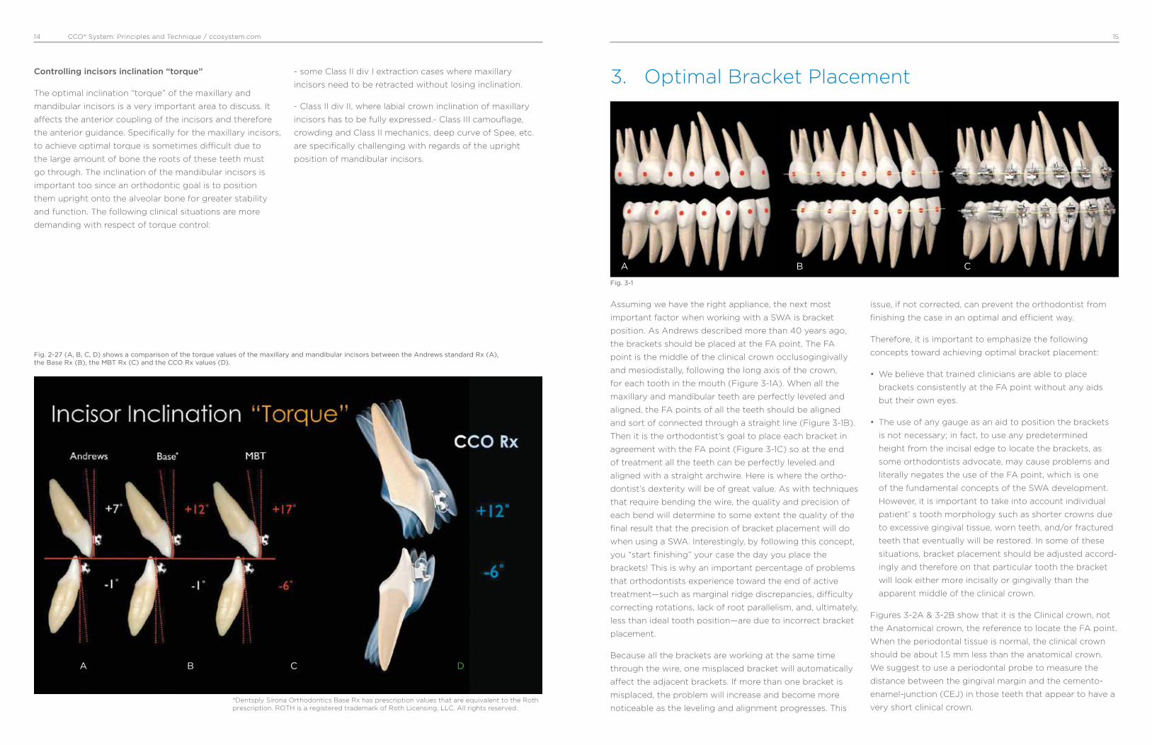
Fig. 2-21 & 2-22 show the before and after of second molar torque control with a transpalatal bar.
Fig. 2-19 & 2-20Notice the buccal axial inclination of maxillary molars and lingual axial incli-nation of mandibular molars. (diagrams from “Orthodontics, Principles and
Practice”, Graber, Second Edition 1967. page 200 and 201.)

CCO® System: Principles and Technique / ccosystem.com 1312
Closer look at the CCO Molar Tubes
The new CCO tubes were developed with three concepts
in mind: control, easy placement and optimal occlusion
(intercuspation). The mesio-distal length of the tubes was
increased providing excellent tipping and rotational control.
The bigger surface area also provides better adhesion
when working with bondable tubes. A notch has been
placed toward the occlusal side of the base, which facili-
tates tube position against the groove of the molars, an
important reference for the molars in the Straight Wire
Appliance. The mesial and distal entrance of the tubes were
made similar to a “cone” shape or better like a “trumpet”,
facilitating wire placement. Also, the occlusal profile of
the tubes was reduced diminishing considerably any tube
interference when coupling the occlusion at the final stage.
Finally, the CCO Rx was adjusted to provide better torque
control.
Fig. 2-23(A, B, C, D)
A
A
B
B
C
C
D
Maxillary CCO Molar Tubes in action
Fig. 2-25 A, B and C show the maxillary molars CCO tubes in action. Fig A and B show a second molar rotated before and after it has been corrected ( wire .014” Sentalloy on A, and .019” x .025” ss on B). C, shows first and second molars aligned on a .019” x .025” ss archwire. Notice the proper alignment of the buccal cusps as well as the occlusal grooves.
A B C
Mandibular CCO Molar Tubes in action
Fig. 2-25 A, B and C show the mandibular molars CCO tubes in action. Fig A and B show an occlusal view of the first and second molars properly aligned with a .019” x .025” ss archwire. C, shows lower molars with their proper inclination with a .019” x .025” ss archwire.
A B C
*
*Dentsply Sirona Orthodontics Base Rx has prescription values that are equivalent to the Roth prescription. ROTH is a registered trademark of Roth Licensing, LLC. All rights reserved.
CCO® System: Principles and Technique / ccosystem.com 1514
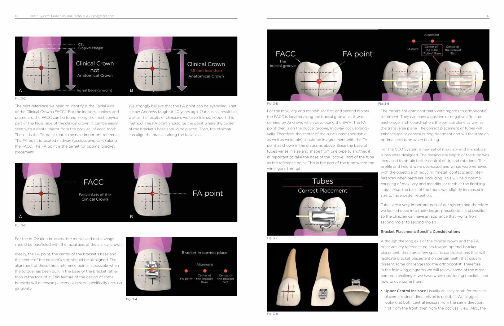
Controlling incisors inclination “torque”
The optimal inclination “torque” of the maxillary and
mandibular incisors is a very important area to discuss. It
a�ects the anterior coupling of the incisors and therefore
the anterior guidance. Specifically for the maxillary incisors,
to achieve optimal torque is sometimes di¡cult due to
the large amount of bone the roots of these teeth must
go through. The inclination of the mandibular incisors is
important too since an orthodontic goal is to position
them upright onto the alveolar bone for greater stability
and function. The following clinical situations are more
demanding with respect of torque control:
- some Class II div I extraction cases where maxillary
incisors need to be retracted without losing inclination.
- Class II div II, where labial crown inclination of maxillary
incisors has to be fully expressed.- Class III camouflage,
crowding and Class II mechanics, deep curve of Spee, etc.
are specifically challenging with regards of the upright
position of mandibular incisors.
Fig. 2-27 (A, B, C, D) shows a comparison of the torque values of the maxillary and mandibular incisors between the Andrews standard Rx (A), the Base Rx (B), the MBT Rx (C) and the CCO Rx values (D).
A B C D
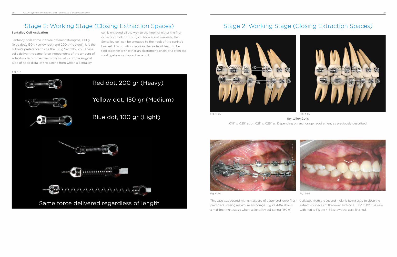
3. Optimal Bracket Placement
A B C
Assuming we have the right appliance, the next most
important factor when working with a SWA is bracket
position. As Andrews described more than 40 years ago,
the brackets should be placed at the FA point. The FA
point is the middle of the clinical crown occlusogingivally
and mesiodistally, following the long axis of the crown,
for each tooth in the mouth (Figure 3-1A). When all the
maxillary and mandibular teeth are perfectly leveled and
aligned, the FA points of all the teeth should be aligned
and sort of connected through a straight line (Figure 3-1B).
Then it is the orthodontist’s goal to place each bracket in
agreement with the FA point (Figure 3-1C) so at the end
of treatment all the teeth can be perfectly leveled and
aligned with a straight archwire. Here is where the ortho-
dontist’s dexterity will be of great value. As with techniques
that require bending the wire, the quality and precision of
each bend will determine to some extent the quality of the
final result that the precision of bracket placement will do
when using a SWA. Interestingly, by following this concept,
you “start finishing” your case the day you place the
brackets! This is why an important percentage of problems
that orthodontists experience toward the end of active
treatment—such as marginal ridge discrepancies, di¡culty
correcting rotations, lack of root parallelism, and, ultimately,
less than ideal tooth position—are due to incorrect bracket
placement.
Because all the brackets are working at the same time
through the wire, one misplaced bracket will automatically
a�ect the adjacent brackets. If more than one bracket is
misplaced, the problem will increase and become more
noticeable as the leveling and alignment progresses. This
issue, if not corrected, can prevent the orthodontist from
finishing the case in an optimal and e¡cient way.
Therefore, it is important to emphasize the following
concepts toward achieving optimal bracket placement:
• We believe that trained clinicians are able to place
brackets consistently at the FA point without any aids
but their own eyes.
• The use of any gauge as an aid to position the brackets
is not necessary; in fact, to use any predetermined
height from the incisal edge to locate the brackets, as
some orthodontists advocate, may cause problems and
literally negates the use of the FA point, which is one
of the fundamental concepts of the SWA development.
However, it is important to take into account individual
patient’ s tooth morphology such as shorter crowns due
to excessive gingival tissue, worn teeth, and/or fractured
teeth that eventually will be restored. In some of these
situations, bracket placement should be adjusted accord-
ingly and therefore on that particular tooth the bracket
will look either more incisally or gingivally than the
apparent middle of the clinical crown.
Figures 3-2A & 3-2B show that it is the Clinical crown, not
the Anatomical crown, the reference to locate the FA point.
When the periodontal tissue is normal, the clinical crown
should be about 1.5 mm less than the anatomical crown.
We suggest to use a periodontal probe to measure the
distance between the gingival margin and the cemento-
enamel-junction (CEJ) in those teeth that appear to have a
very short clinical crown.
Fig. 3-1
*
*Dentsply Sirona Orthodontics Base Rx has prescription values that are equivalent to the Roth prescription. ROTH is a registered trademark of Roth Licensing, LLC. All rights reserved.
CCO® System: Principles and Technique / ccosystem.com 1716
The next reference we need to identify is the Facial Axis
of the Clinical Crown (FACC). For the incisors, canines and
premolars, the FACC can be found along the most convex
part of the facial side of the clinical crown. It can be easily
seen with a dental mirror from the occlusal of each tooth.
Then, it is the FA point that is the next important reference.
The FA point is located midway (occlusogingivally) along
the FACC. The FA point is the target for optimal bracket
placement.
We strongly believe that the FA point can be eyeballed. That
is how Andrews taught it 40 years ago. Our clinical results as
well as the results of clinicians we have trained support this
method. The FA point should be the point where the center
of the bracket’s base should be placed. Then, the clinician
can align the bracket along the facial axis.
Fig. 3-2
Fig. 3-3
Fig. 3-4
A
A
B
B
For the In-Ovation brackets, the mesial and distal wings
should be paralleled with the facial axis of the clinical crown.
Ideally, the FA point, the center of the bracket’s base and
the center of the bracket’s slot, should be all aligned. The
alignment of these three reference points is possible when
the torque has been built in the base of the bracket rather
than in the face of it. This feature of the design of some
brackets will decrease placement errors, specifically occluso-
gingivally
For the maxillary and mandibular first and second molars
the FACC is located along the buccal groove, as it was
defined by Andrews when developing the SWA. The FA
point then is on the buccal groove, midway occlusogingi-
vally. Therefore, the center of the tube’s base (bondable
as well as weldable) should be in agreement with the FA
point as shown in the diagrams above. Since the base of
tubes varies in size and shape from one type to another, it
is important to take the base of the “active” part of the tube
as the reference point. This is the part of the tube where the
wires goes through.
The molars are dominant teeth with regards to orthodontic
treatment. They can have a positive or negative e�ect on
anchorage, arch coordination, the vertical plane as well as
the transverse plane. The correct placement of tubes will
enhance molar control during treatment and will facilitate an
optimal occlusion when finishing.
For the CCO System, a new set of maxillary and mandibular
tubes were designed. The mesiodistal length of the tube was
increased to obtain better control of tip and rotations. The
profile and height were decreased and wings were removed
with the objective of reducing “metal” contacts and inter-
ferences when teeth are occluding. This will help optimal
coupling of maxillary and mandibular teeth at the finishing
stage. Also, the base of the tubes was slightly increased in
size to have better retention.
Tubes are a very important part of our system and therefore
we looked deep into their design, prescription, and position
so the clinician can have an appliance that works from
second molar to second molar!
Bracket Placement: Specific Considerations
Although the long axis of the clinical crown and the FA
point are key reference points toward optimal bracket
placement, there are a few specific considerations that will
facilitate bracket placement on certain teeth that usually
present some challenges for the orthodontist. Therefore,
in the following diagrams we will review some of the most
common challenges we have when positioning brackets and
how to overcome them.
• Upper Central Incisors: Usually an easy tooth for bracket
placement since direct vision is possible. We suggest
looking at both central incisors from the same direction,
first from the front, then from the occlusal view. Also, the
Fig. 3-5
Fig. 3-7
Fig. 3-8
Fig. 3-6

CCO® System: Principles and Technique / ccosystem.com 1918
incisal edge of the tooth should not be used as a reference
to make it parallel to the edge of the bracket’s base as
many clinicians do. This can be misleading if there is any
wear in part or all the incisal edge of the tooth.
• Upper Lateral Incisors: After the third molars, upper lateral
incisors are the teeth with more problems regarding size
and shape. This makes it di¡cult to determine the long
axis of the crown from the buccal. It is wise to use the
mirror to look at the lingual surface of the incisor and then
extend the long axis of the clinical crown from the lingual
to the buccal.
• Upper Canine: The long axis of the upper canines, which is
also the most convex part of the labial surface, is located
more mesial than the true mesiodistal center of the tooth;
therefore, the FA point looks a little bit more mesial than
the dead center of the tooth. If you err and place the
bracket on the center of the crown mesiodistally, the
canine will rotate mesially. The more convex the canine is
the more rotation will be observed. It is suggested to use
the mirror to look at the canine from the occlusal.
• Upper Premolars: Usually premolars, specifically second
premolars, represent a challenge at the time of bonding
due to lack of direct vision. Then it is advisable to look with
the mirror from the occlusal and the buccal to locate the
FA point and the long axis of the clinical crown.
• Upper Molars: The landmark that Andrews used as the
long axis of the clinical crown for the molar is the buccal
groove. The FA point then lies along the buccal groove,
midway occlusogingivally. It is important to realize that the
center of the tube mesiodistally should be in agreement
with the FA point. As some manufacturers have reduced
the mesiodistal length of tubes, orthodontists have started
positioning tubes too far mesial with the consequential
distal overrotation of the molars.
• Lower Central Incisors: Excessive crowding, loss of
proper gingival contour as well as wear facets and/or
small fractures of the incisal edge are the most common
problems challenging optimal bracket placement. We
strongly suggest looking at these teeth from the front,
occlusal, and lingual view to determine the proper long
axis of the clinical crown. We have observed a tendency
to place the bracket too incisally on these teeth. It is
important to respect the middle third of the clinical crown
(clinical crown is 1.5 mm less than the anatomical crown).
• Lower Canines: As well as for the upper canine, the long
axis of the lower canines is the most convex part of the
labial surface. It is also located more mesial than the true
mesiodistal center of the tooth. The FA point then looks
a little more mesial than the dead center of the tooth.
If you err and place the bracket on the center of the
crown mesiodistally, the canine will rotate mesially. It is
suggested to use the mirror to look at the canine from
the occlusal when positioning the bracket.
• Lower Premolars: The same challenge as for the upper
Pm. There is not good direct vision. Again, for these teeth,
it is suggested to look with the mirror from the occlusal
and the buccal to locate the FA point and the long axis of
the clinical crown. It will take only a few bondings before
the clinician feels very comfortable using the mirror as an
aid for bracket placement.
• Lower Molars: The same as for the upper molars. The
landmark that Andrews used as the long axis of the
clinical crown for the lower molars is the buccal groove.
The FA point then lies along the buccal groove, midway
occlusogingivally. The center of the tube mesiodistally
should be in agreement with the FA point as previously
discussed. This will prevent the commonly seen distal
overrotation of the molars.

CCO® System: Principles and Technique / ccosystem.com 2120
For didactic purposes, treatment mechanics has been
usually divided into different stages, from three to
seven, depending on authors’ preference. Simplicity is
of paramount importance when teaching, and therefore
all the mechanics to be accomplished in our orthodontic
treatments with the CCO System can be divided into three
stages: stage 1, leveling and aligning; stage 2, working
stage; and stage 3, finishing stage.
At each of these stages there are specific movements of
teeth that will occur and specific goals that have to be
achieved before continuing to the next stage of treatment.
It is important to emphasize that both the treatment
outcome and its efficiency will be greatly improved if the
orthodontist follows these stages. The following stages of
treatment mechanics, with their respective wire sequence,
have been tailored for the CCO System.
Excellent treatment mechanics should allow the ortho-
dontist not only to deliver optimal treatment to the
majority of his or her patients achieving the esthetic and
functional predetermined goals but also to do it in the most
efficient and simple way. Time is a valuable resource for
both the orthodontist and the patient as well.
Leveling and aligning is a complex process where all the
crowns are moving at the same time and in different
directions. As the teeth level and align, reciprocal forces
between them develop, which can be of great help to guide
the movements to our advantage. Then, when possible,
all teeth should be engaged from the beginning to obtain
maximum efficiency of tooth movement.
Usually at this stage, round, small-diameter, thermal-
activated wires, such as a .014” Sentalloy for severe
crowding, or an .018” Sentalloy for moderate to minimum
crowding, are preferred. It is recommended to place
crimpable stops to avoid undesirable movement of the
wire, which can cause discomfort to the patient. These
round wires can be in place for as long as 8 to 12 weeks
before proceeding to the next wire, which usually is a
.020” × .020” BioForce.
The BioForce wire is a low-deflection, thermal-activated
wire that works very well as a transitional wire from Stage
1 to Stage 2. The .020” × .020” BioForce corrects most of
the rotations left by the previously used round wires and
provides more stiffness to start leveling the curve of Spee
and therefore flatten the occlusal plane. It is important to
note that even if you could start treatment with a rectan-
gular or square thermal-activated, low-deflection wire, with
the assumption of saving time and providing torque from
the beginning of treatment, this is absolutely not recom-
mended, since it may cause loss of posterior anchorage.
This happens for two main reasons: first, the only teeth
with positive labial crown torque are the maxillary central
and lateral incisors, and second, the mesial crown tip of the
maxillary and mandibular canines is rather large. Therefore,
if we start treatment resolving the crowding with a rectan-
4. Treatment Mechanics
Stage 1: Leveling and Aligning
Stage 1 Leveling and Alignment
A
B
Stage 2 Working Stage
Stage 3 Finishing Stage
QualityEfficiency
SimplicityConsistency
gular or square wire, we are providing labial crown torque
to the maxillary incisors and mesial crown tip to canines,
which will increase our anchorage in the front part of the
arch facilitating the loss of anchorage in the posterior part
of the arch.
This is critical in cases where the treatment plan calls for
maximum retraction of the maxillary and or mandibular
incisors. Conversely, if we start treatment with a round wire
of small diameter, we will not provide torque and the tip
effect on the canines will be minimal. This will allow the
molar and premolars to level, align, and upright, which will
produce a “lasso” effect on the incisors that will upright
and sometimes even retract them.
The .020” × .020” BioForce will make the clip of the SLB
active and thus start delivering torque; nonetheless, its
strength is not sufficient to compromise the anchorage
that has already been created with the round wires. Usually,
after 8 to 10 weeks with the .020” × .020” BioForce, the
stage 1 of leveling and aligning is finished, and in the
author‘s opinion it is the first time to evaluate bracket
placement and debond/rebond as necessary. Then, we are
ready to start Stage 2, the Working Stage.
Movements we should expect and goals we
should accomplish when Leveling and Aligning
before starting Stage 2:
• Teeth move individually
• Mainly crown movement
• Molars and Pm derotate and upright distally
• Incisors upright and sometimes even retract
• Mainly round, small diameter, superelastic wires (ideal
thermoelastic)
• Square or rectangular superelastic wires to completely
correct rotations
• Before going on to Stage 2, check bracket position (gross
errors) and debond/rebond as indicated
Arch Wire Selection
Stage 1 Severe to Moderate Crowding
Type Size / Sequence
Sentalloy* .014”
.018”
BioForce* .020” x .020”
Stage 1 Mild Crowding
Type Size / Sequence
Sentalloy* .018”
BioForce* .020” x .020”
*Sentalloy and BioForce are Thermalactivated wires
Stage 1: Leveling and Aligning

CCO® System: Principles and Technique / ccosystem.com 2322
Figures 4-1A and 4-1B show the reciprocal forces that occur
at the time of initial alignment. In a reduced-friction system,
the canines will move back to the extraction space without
any forward movement of the incisors. The extra amount
of wire will move back distal of second molars. The bigger
the amount of crowding , the bigger the amount of wire
that will protrude distal of the last tooth when leveling and
aligning.
Figures 4-2A and 4-2B show the distal tip of the upper
and lower molars and premolars built into the CCO Rx.
As the molars and premolars level and align, they also
upright. This, together with the force of the lips, will provide
posterior anchorage allowing the incisors to upright, even
retract, and consequently improve the overbite and overjet.
Stage 1: Leveling and Aligning
Reciprocal Anchorage Reciprocal AnchorageLips
0° 0°
-1°D -1°D-1°D -1°D-1°D -1°D
0° 0°0° 0°
Lips
Fig. 4-1A
Fig. 4-2A
Fig. 4-1B
Fig. 4-2B
Stage 1: Leveling and Aligning
As shown in Figures 4-3A to 4-3D, as the initial alignment
occurs, molars upright and the maxillary and mandibular
plane of occlusion become more parallel. The incisors
upright and even retract, and the overbite improves.
The wire sequence is very important to control tipping,
rotations and torque. Small, round Sentalloy wires such
as .014” (4-3B) and .018” (4-3C) are excellent to control
initial alignment, upright incisors, premolars and molars,
and correct major rotations. BioForce wires such as
.020” x .020” (4-3D) are ideal to finish with the leveling and
aligning stage. This wire will finish correcting the rotations
still present after the round wires. It will also express more
crown tipping and will start providing a small amount of
torque since its dimension will mildly activate the springing
clip of the bracket.
Figures 4-4A and 4-4B show how as the initial alignment
occurs, molars upright and the maxillary and mandibular
plane of occlusion become more parallel helping uprighting
and even retracting the incisors and also improving the
overbite. Fig. 4-5A to 4-5C show the sequence from an
initial .014” Sentalloy (4-5A) to a .018” Sentalloy (4-5B) to a
.020” x .020” BioForce wire (4-5C). No elastics or extraoral
force has been used.
Fig. 4-3A
Fig. 4-3C
Fig. 4-3B
Fig. 4-3D

CCO® System: Principles and Technique / ccosystem.com 2524
Stage 1: Leveling and Aligning
0° 0°
-1°D -1°D
Fig. 4-4A Fig. 4-4B
Fig. 4-5A
Fig. 4-5C
Fig. 4-5B
Stage 1: Leveling and Aligning
Stage 2: Working Stage
Figures 4-6A to 4-6D show another example of the
favorable clinical effects of the distal-tip built into the
molars and premolars to parallel the upper and lower
occlusal planes. As the maxillary and mandibular occlusal
planes become parallel, the open bite closes. Initial leveling
and aligning using light forces minimizes the extrusion of
molars, which are held in the same vertical position by the
normal occlusal masticatory forces.
This stage of treatment is the one on which we will spend
more time. At this stage, the maxillary and mandibular
arches are coordinated, proper overbite and overjet are
achieved, Class II or Class III are corrected, maxillary and
mandibular midlines are aligned, extraction spaces are
closed, and maxillary and mandibular occlusal planes are
paralleled. Although most of these corrections happen
simultaneously, we will describe them separately for
didactic reasons so key points can be emphasized.
Arch Coordination
The maxillary and mandibular archwires must be coordi-
nated in order to obtain a stable occlusal intercuspation
and proper overjet. In an ideal intercuspation of a Class I,
one-tooth to two-teeth occlusal scheme, the palatal cusps
of the maxillary molars should intercuspate with the fossae
and marginal ridges of mandibular molars, the buccal cusp
of the mandibular premolars should intercuspate with
the marginal ridges of the maxillary premolars, and the
mandibular canines and incisors should intercuspate with
marginal ridges of the maxillary canines and incisors. If
this occlusal scheme occurs, it will then provide an overjet
of 2 to 3 mm all around the arch from second molar to
second molar. Then, the maxillary archwire must be 2 to
3 mm wider than the mandibular archwire. The archwire
coordination is done with the stainless steel wire. Even if
Fig. 4-6A
Fig. 4-6C
Fig. 4-6B
Fig. 4-6D

CCO® System: Principles and Technique / ccosystem.com 2726
Stage 2: Working Stage
they come preformed, the clinician should not rely on it and
check them before insertion.
Another important aspect of arch coordination is the
effect that it has on the vertical dimension and the sagittal
dimension. Arch coordination is a transverse issue. The
maxillary teeth should be upright and centered in the
alveolar/basal bone and coordinated with the mandibular
teeth, which should also be upright and centered in the
alveolar/basal bone to obtain a proper intercuspation.
Often this is not the case and we find maxillary molars
buccally inclined, also referred as an accentuated curve of
Wilson, which can produce contacts between the palatal
cusp of maxillary molars and the inclines of the mandibular
molars. This decreases the overbite and sometimes
produces even an openbite (vertical problem), which in
turn can produce a downward and backward movement of
the mandible (sagittal problem). This phenomenon is due
to the lack of palatal crown torque of the maxillary molars.
The torque values for the molars in the CCO Rx should take
care of this problem for the most part. However, in severe
cases, we can add palatal crown torque to the working wire
or use transpalatal bars (TPB), which are very effective
delivering torque.
Overbite and Overjet Correction
An optimal overbite/overjet relationship does not have to
be a certain predetermined number of millimeters. More
important is the functional relationship they have. This
means that the overbite/overjet should be compatible with
a mutually protected occlusal scheme and thus allows
for a proper anterior guidance in protrusion and lateral
excursive movements. Although, as we said, the number of
millimeters is less important than the function; we find that
an optimal overbite is usually around 4 mm and an optimal
overjet is 2 to 3 mm.
When diagnosing and treatment planning overbite/overjet
problems, it is important to take the following key points
into consideration: arch space management, position of
the mandible in centric relation, and relationship of the
upper/lower incisors with the lips. Arch space management
is important to understand since the SWA tend to flatten
the curve of Spee, which requires space in the arch. If
not enough space is available or created, the incisors will
procline, increasing the arch perimeter. This incisor procli-
nation will also decrease the overbite and may help, if it
only occurs in the lower arch, to decrease the overjet.
Flattening the maxillary and mandibular occlusal planes
proclining the incisors can be of help in deep bite cases.
When the incisors are not allowed to procline, space in the
arch must be created. This is specifically important to avoid
periodontal problems in cases with thin bone surrounding
the incisors area. Advanced diagnostic imaging tools such
as the CBCT could be of great help to precisely identify the
condition of the bone in this area. Up to 4 to 6 mm can be
created with interproximal reduction of teeth, usually done
on the incisors and, less often, the canines and premolars.
If more than 6 mm of space is required, extraction of
premolars could be indicated.
Another important factor to consider when evaluating
overbite/overjet problems is the position of the mandible.
Often, differences between a maximum intercuspation
(MIC) and centric relation (CR) can produce significant
differences in the overbite/overjet relationship. In many
cases we find that as the mandible rotates close in CR, a
primary contact, usually at the second molar, keeps the
bite open in the anterior, decreasing the overbite and
preventing the mandible to achieve a more stable occlusal
scheme.
At last, but by no means the least important, is the sagittal
and vertical relationship of the maxillary and mandibular
incisors with the lips. In an openbite case, should we
intrude the molars or extrude the incisors? In a deep bite
case, should we intrude the maxillary incisors, the lower,
both? These basic but very important questions can
be answered through an understanding of the optimal
relationship of the incisors with the lips. According to
contemporary aesthetic trends and taking into account the
aging process for adolescents and young adults, maxillary
incisors should have, at rest, an exposure of about 4 mm
beyond the most inferior point of the upper lip known as
upper stomion. As explained earlier, an optimal functional
overbite should be about 4 mm. Now, if we put together
the last two concepts, the incisal edge of the lower incisors
should be at the same level with the most inferior point
of the upper lip. Therefore, any vertical change of the
incisors will affect not only the function through changes
of the anterior guidance but also the aesthetics through
the amount of tooth exposure. These anterior functional/
esthetic references explained by Ayala as the “upper
Stage 2: Working Stage
stomion concept” will help the clinician to determine the
best strategies to correct overbite/overjet problems and
will be of special importance for planning cases involving
orthognathic surgery.
Movements that should be expected and goals
that should be achieved before starting Stage 3.
• Movement of group of teeth in all planes of the space:
Sagittal, Vertical and Transverse
• OJ/OB correction
• Class II and III correction
• Close all remaining extraction spaces
• Finish leveling the occlusal plane
• Arch coordination
Arch Wire Selection
Stage 2 Non-Extraction
Type Size / Sequence
SW Stainless Steel .019” x .025”
BioForce* .019” x .025”
*BioForce is a Thermalactivated wire
Closing Extraction Spaces
Usually after leveling and aligning, the extraction spaces left
are smaller than at the beginning of treatment since some
of the space has been taken to unravel the initial crowding
and to upright the maxillary and mandibular incisors, as
described earlier in this manual. Also, the maxillary and
mandibular occlusal planes should be flat or almost flat, and
the six anterior teeth should be consolidated into one unit.
Then, to efficiently close the remaining spaces, achieving
the desired functional and aesthetic goals, we need to
determine the anchorage requirement. This will allow us
to know which teeth should be moved more mesially or
distally and therefore to choose the appropriate mechanics.
We believe that one of the easiest ways to determine the
anchorage requirement is to perform a visual treatment
objective (VTO). The VTO is a cephalometric exercise where
we modify the patient’s cephalometric tracing to achieve
the desired “end of treatment” result and then, by super-
imposing both tracings, we can visualize the movements
that need to occur to obtain that result. The VTO is not a
formula or equation that will determine or impose a specific
type of treatment but rather an exercise where we take into
account our experience gathered from other similar cases,
an estimation of the growth the patient will have during
treatment, the patient’s biotype and soft tissue character-
istic, and so on to more accurately treatment plan our cases
and have a visual representation of it. Thus, after the VTO
has been performed, the anchorage requirement can be
minimum, medium, or maximum.
Before describing each one of these anchorage situa-
tions, it is important to indicate the wires and auxiliaries
used at this stage. In our mechanics, we use a straight wire
with hooks and Sentalloy coils (Sentalloy is a trademarked
brand of Dentsply Sirona, Islandia, NY). The wire is stainless
steel and can be either 0.019” × 0.025” or 0.021” × 0.025”,
depending on the anchorage situation. The Sentalloy coils
can be light (100 g), medium (150 g), or heavy (200 g). The
most common coil I use is the medium (150 g). It works very
well in all kinds of anchorage situations. It is important to
remember that when the anchorage situation calls for it, we
use some auxiliaries to enhance the posterior anchorage.
Auxiliaries such as TPBs, temporary anchorage devices
(TADs), and/or the use of extraoral anchorage such as High
Pull or Cervical Head Gear.
CCO® System: Principles and Technique / ccosystem.com 2928
Red dot, 200 gr (Heavy)
Yellow dot, 150 gr (Medium)
Blue dot, 100 gr (Light)
Same force delivered regardless of length
Fig. 4-7
Sentalloy Coil Activation
Sentalloy coils come in three di�erent strengths, 100 g
(blue dot), 150 g (yellow dot) and 200 g (red dot). It is the
author’s preference to use the 150 g Sentalloy coil. These
coils deliver the same force independent of the amount of
activation. In our mechanics, we usually crimp a surgical
type of hook distal of the canine from which a Sentalloy
coil is engaged all the way to the hook of either the first
or second molar. If a surgical hook is not available, the
Sentalloy coil can be engaged to the hook of the canine’s
bracket. This situation requires the six front teeth to be
tied together with either an elastomeric chain or a stainless
steel ligature so they act as a unit.
Stage 2: Working Stage (Closing Extraction Spaces)Stage 2: Working Stage (Closing Extraction Spaces)
This case was treated with extractions of upper and lower first
premolars utilizing maximum anchorage. Figure 4-8A shows
a mid-treatment stage where a Sentalloy coil spring (150 g)
activated from the second molar is being used to close the
extraction spaces of the lower arch on a .019” x .025” ss wire
with hooks. Figure 4-8B shows the case finished.
Fig. 4-8A Fig. 4-8B
Sentalloy Coils
.019” x .025” ss or .021” x .025” ss. Depending on anchorage requirement as previously described.
Fig. 4-9A Fig. 4-9B

CCO® System: Principles and Technique / ccosystem.com 3130
Stage 2: Working Stage (Closing Extraction Spaces)
Medium Anchorage
Fig. 4-10
UnderstandingAnchorage Requirement
• Minimum VTO3
• Medium / Reciprocal
• Maximum
Arch Wire Selection
Stage 2 Extraction
Type Size Sequence
Stainless Steel .019” x .025” Depends on
.021” x .025”
Visual Treatment
Objective in all
3 dimensions with hooks Anchorage Requirement
Upper and Lower archwires: .019” x .025” SS
Schemes showing the placement of the crimpable hooks and Sentalloy coils. Example A shows the space open and B the space closed.
This is the most common anchorage situation we will
encounter in our cases. Medium anchorage means that
the remaining spaces should be closed reciprocally. For
this situation, we use a .019” × .025” wire. The activation of
the Sentalloy coils is done, most of the time, from the first
molar. However, it can also be done from the second molars
depending on how the case is progressing. The bone and
attachment apparatus is not the same for every patient
and, therefore, the response to the closing mechanic could
di�er between cases. Then, a clinical examination of the
overbite/overjet, canine and molar relationship, and facial
aesthetic should be done at each visit to evaluate any
changes in activation that may be required. This should not
take any extra time since the management of the Sentalloy
coil is a rather easy procedure.
Stage 2: Working Stage (Closing Extraction Spaces)
In a maximum anchorage situation, most of the remaining
space left after leveling and aligning is closed due to distal
movement of the anterior teeth. We use a .019” × 0.025”
wire. The Sentalloy coil is activated from the second molars.
Although not frequently required, auxiliaries to enhance
posterior anchorage such as TPB, TADs, or extraoral force
(headgear) can be used as needed.
Maximum Anchorage
Upper and Lower archwires: .019” x .025” SS
Schemes showing the placement of the crimpable hooks and Sentalloy coils. Example A shows the space open and B the space closed.
Transpalatal Bars High Pull Head Gear
Fig. 4-11-A
Fig. 4-11-B Fig. 4-11-C

CCO® System: Principles and Technique / ccosystem.com 3332
Stage 2: Working Stage (Closing Extraction Spaces)
In a minimum anchorage situation, molars will be moved
mesially to close the remaining extraction spaces. We use
a .021” × .025” wire. This wire will express the buccal crown
torque of the maxillary incisors and the mesial tip of the
canines. In the mandible, this wire will express the mesial
tip of the canine. This situation will increase the anchorage
in the anterior part of the mouth since it would be more
di¡cult to retract or even tip back the anterior teeth while
moving the molars forward. The activation of the Sentalloy
coils must be done from the first molars. Then, after the
first molar has been moved forward as desired, the second
molar can be activated and moved forward too. Often
though, this is not required since the second molars will
travel forward as we move the first molars and then the
space remaining between the first and second molars will
be very small and easily closed with an elastomeric chain.
Minimum Anchorage
Schemes showing the placement of the crimpable hooks and Sentalloy coils as well as the sequence of movements from A to D.
A
C
B
D
Fig. 4-12
Stage 2: Working Stage (Closing Extraction Spaces)
Figures 4-13A to 4-13D show a Class II case treated with
extractions of maxillary first premolar and mandibular
second premolars. Minimum anchorage was used for
the mandibular arch. Fig. 4-13A shows the pretreatment
intraoral pictures of the right side. Fig. 4-13B shows a lower
.021”x .025” ss DKL activated with a ss ligature from
the first molar to move it mesially to a Class I. The .021”x
.025” ss DKL provides su¡cient anchorage of the anterior
segment. Fig. 4-13C shows the posttreatment picture. Fig.
4-13D shows the superimposition of the pre and post-
mandibular tracings where one can notice the mesial
movement of the molars.
Minimum Anchorage
Fig. 4-13A
Fig. 4-13C
Fig. 4-13B
Fig. 4-13D
CCO® System: Principles and Technique / ccosystem.com 3534
Stage 2: Working Stage (Closing Extraction Spaces)
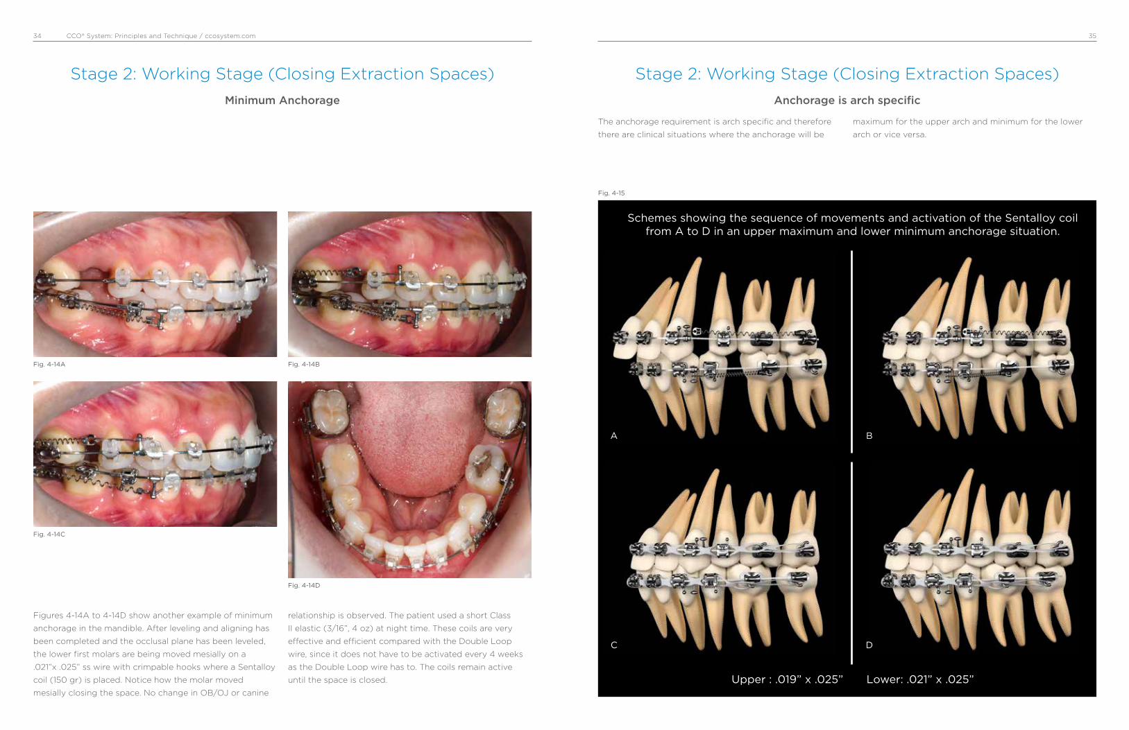
Figures 4-14A to 4-14D show another example of minimum
anchorage in the mandible. After leveling and aligning has
been completed and the occlusal plane has been leveled,
the lower first molars are being moved mesially on a
.021”x .025” ss wire with crimpable hooks where a Sentalloy
coil (150 gr) is placed. Notice how the molar moved
mesially closing the space. No change in OB/OJ or canine
relationship is observed. The patient used a short Class
II elastic (3/16”, 4 oz) at night time. These coils are very
e�ective and e¡cient compared with the Double Loop
wire, since it does not have to be activated every 4 weeks
as the Double Loop wire has to. The coils remain active
until the space is closed.
Minimum Anchorage
Fig. 4-14A
Fig. 4-14C
Fig. 4-14B
Fig. 4-14D
The anchorage requirement is arch specific and therefore
there are clinical situations where the anchorage will be
maximum for the upper arch and minimum for the lower
arch or vice versa.
Anchorage is arch specific
Schemes showing the sequence of movements and activation of the Sentalloy coil from A to D in an upper maximum and lower minimum anchorage situation.
Upper : .019” x .025” Lower: .021” x .025”
A
C
B
D
Fig. 4-15
Stage 2: Working Stage (Closing Extraction Spaces)

CCO® System: Principles and Technique / ccosystem.com 3736
Discretion is a good word to describe the use of inter-
maxillary elastics. We use them and like them, but it is
important to understand how they are used in these
mechanics to avoid problems.
We do not use intermaxillary elastics in the following situa-
tions:
• Round wires
• Initial leveling and aligning, low-deflection wires
• To a terminal tooth, last tooth in the arch
• In the anterior part of the mouth to close openbites
• In the posterior part of the mouth to correct crossbites
• For a long extended period of time
We use intermaxillary elastics in the following situations:
• At the working and finishing stages
• On square or rectangular stainless steel wires
• On the buccal side of the mouth, short Class II or III
and/or triangular verticals
The three types of intermaxillary elastics we commonly use
are 3/16-inch 4 oz, 6 oz, and 8 oz elastics. Short means,
in a Class II for instance, from the maxillary canine to the
mandibular second premolar in a nonextraction case and to
the first mandibular molar in an extraction case.
Intermaxillary Elastics
Fig. 4-16A Fig. 4-16BShort double Class II 3/16” 6 oz.
Maxillary and mandibular
.019” x .025” ss wires.
Short Class III 3/16” 6 oz.
Maxillary .021” x .025” ss and
mandibular .019” x .025” ss wires.
Stage 2: Working Stage (Closing Extraction Spaces) Stage 2: Working Stage (Distal movement of maxillary molars with open coils)
There are some cases where the distal movement of
maxillary first and second molars is a great solution to
correct Class II dental relationships. Open coils provide an
easy and e¡cient way to distalize molars without losing
control. However, certain precautions must be taken into
account:
• It only provides a dental correction
• Useful in cases where no more than 3 mm of correction is
needed
• It is not indicated in severe vertical cases
• The maxillary occlusal plane must be leveled
• To allow enough sliding with tooth control, a .019”x .025”
ss wire is preferred
• Anchorage of the anterior segment is provided by
using short Class II elastics. TADs can be also used in
non-compliance patients
open coil open coil expressedmolars
move back
A B
Fig. 4-17

CCO® System: Principles and Technique / ccosystem.com 3938
Stage 2: Working Stage (Distal movement of maxillary molars with open coils)
Fig. 4-18A shows an open coil compressed between
maxillary second premolar and first molar. The coil must
be compressed as much as possible, and the archwire
must be left long about 1 to 2 mm to allow the molars to
slide though it. A Class II 4 oz. from maxillary canine to
mandibular second premolar is used as anchorage to avoid
maxillary canine and incisors to move forward. Fig. 4-18B
shows maxillary first and second molars distalized to a
Class I relationship.
After molars have been moved into Class I, the open coil
is placed between maxillary first and second premolars to
move the second premolar distally. Then, between canine
and first premolar to move the first premolar distally. The
Class II 4 oz must be used at all times. Figs. 4-18C and
4-18D show the open coil in place before and after the
distal movement of the maxillary second premolar.
A
C
B
D
Fig. 4-18
Stage 2: Working Stage (Distal movement of maxillary molars with open coils
“Step by Step”)
Fig. 4-19A
Fig. 4-19C
Fig. 4-19E
Fig. 4-19B
Fig. 4-19D
Fig. 4-19F
Intraoral photos before treatment. Class II canines and end-on first molars on the right side.
In-Ovation ‘R’ brackets and upper and lower .014” Sentalloy Medium wires.
Upper .020”x .020” Bioforce Medium wires to complete the stage of leveling and aligning.

CCO® System: Principles and Technique / ccosystem.com 4140
Fig. 4-19G
Fig. 4-19I
Fig. 4-19K
Fig. 4-19H
Fig. 4-19J
Fig. 4-19L
Beginning of working stage with an upper and lower .019”x .025” ss wire. The occlusal plane has been leveled. An open coil has been placed between the second premolar and first molar. A short
Class II 4 oz elastic is used for anchorage (from upper canine to lower second premolar).
First and second molars have been moved distally. The open coil can be easily activated by placing a crimpable stop as shown in the above picture.
More activation of the open coil is needed. Notice the placement of two crimpable stops.
Fig. 4-19M
Fig. 4-19O
Fig. 4-19Q
Fig. 4-19N
Fig. 4-19P
Fig. 4-19R
Upper first and second molar have been moved to a Class I. The occlusal view shows the amount of space gained by the open coil.
The second premolar has been moved distally using the same open coil. Now, the first premolar is being moved distally. A short Class II 4 oz is used as anchorage.
The first premolar has been moved distally using the same open coil. Now, the first canine will be moved distally.
CCO® System: Principles and Technique / ccosystem.com 4342
Fig. 4-19S
Fig. 4-19U
Fig. 4-19W
Fig. 4-19T
Fig. 4-19V
Fig. 4-19X
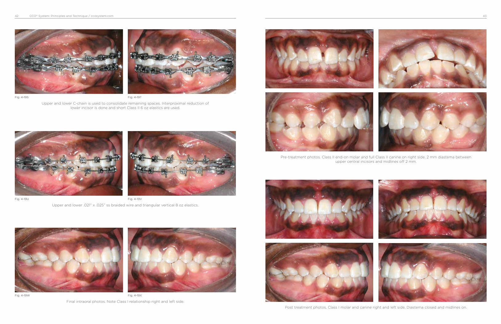
Upper and lower C-chain is used to consolidate remaining spaces. Interproximal reduction of lower incisor is done and short Class II 6 oz elastics are used.
Upper and lower .021” x .025” ss braided wire and triangular vertical 8 oz elastics.
Final intraoral photos. Note Class I relationship right and left side.
Pre-treatment photos. Class II end-on molar and full Class II canine on right side. 2 mm diastema between upper central incisors and midlines off 2 mm.
Post treatment photos. Class I molar and canine right and left side. Diastema closed and midlines on.
CCO® System: Principles and Technique / ccosystem.com 4544
Stage 3: Finishing Stage
In our experience using the In-Ovation bracket system,
which is an active SLB with the clip pushing and sitting the
wire onto the slot, optimal torque expression is achieved
after a .019” × .025” stainless steel has been in place for a
few months. This is especially true in nonextraction cases
with an average curve of Spee. However, in some cases the
size and stiffness of a .021” × .025” stainless steel or .022”
× .028” stainless steel are indicated, such as in cases with
a deep curve of Spee, extraction cases that have required
an important amount of tooth movement, and cases that
required significant labial crown torque of maxillary incisors
such as Class III camouflage cases and Class II, Division 2
cases.
Once the maxillary and mandibular occlusal planes are
parallel and all the bracket slots are aligned, bracket
position should be carefully checked for minor correction
of tooth position and therefore the second time of debond/
rebond should be done. The last wire we use is a stainless
steel multibraided .021” × .025” archwire. Although this
wire is large enough to fill the slot of the bracket and then
maintain the tip, torque, and offset of each tooth, its resil-
ience permits both minor bracket repositioning and “end of
treatment” optimal intercuspation.
It is important to notice that at this point in treatment, all
the appliance interferences should be removed using a
finishing carbide burr on a high-speed handpiece. With
a thin articular paper, all contacts must be checked. Only
tooth-tooth contacts should be allowed. All brackets, tubes,
or band contacts must be removed to allow proper settling.
Vertical triangular 3/16-inch elastics, either 6 oz or 8 oz,
are used to achieve proper intercuspation. These vertical
elastics should not be used with the braided wire for
more than 6 weeks to avoid rolling premolars and molars
lingually, which cannot be detected from the buccal but
rather from the lingual where premolars and/or molars will
not be contacting. Finally, before removing the appliance,
a complete assessment of the occlusal “end of treatment”
goals should be performed. We strive to finish our cases
with a static occlusal scheme compatible with the six keys
of optimal occlusion as described by Larry Andrews and
a dynamic mutually protected occlusal scheme in centric
relation as described by Ronald Roth.
• Fill the bracket slot with a straight wire so optimal tooth
position, in all planes, can be achieved**
• Finishing wire: .019” x .025” or .021” x .025” Braided wire
• Check bracket position - Debond/Rebond as indicated
(minor corrections)
• Short, heavy (3/16” 6-8 oz) Class II, III or vertical triangular
elastics as indicated to achieve optimal intercuspation
**On a traditional ligated .022” slot bracket, a .019” x .025”
ss has about 12° of play. On a Passive SLB the play is even
greater!! However, on an Active SLB (In-Ovation brackets), a
.019” x .025” ss provides full expression of torque.
Arch Wire Selection
Stage 3
Type Size / Sequence
Braided Stainless Steel .019” x .025”
or
.021” x .025”
Stage 3: Finishing Stage
Fig. 4-17A
Fig. 4-17C
Fig. 4-17E
Fig. 4-17B
Fig. 4-17D
Fig. 4-17F
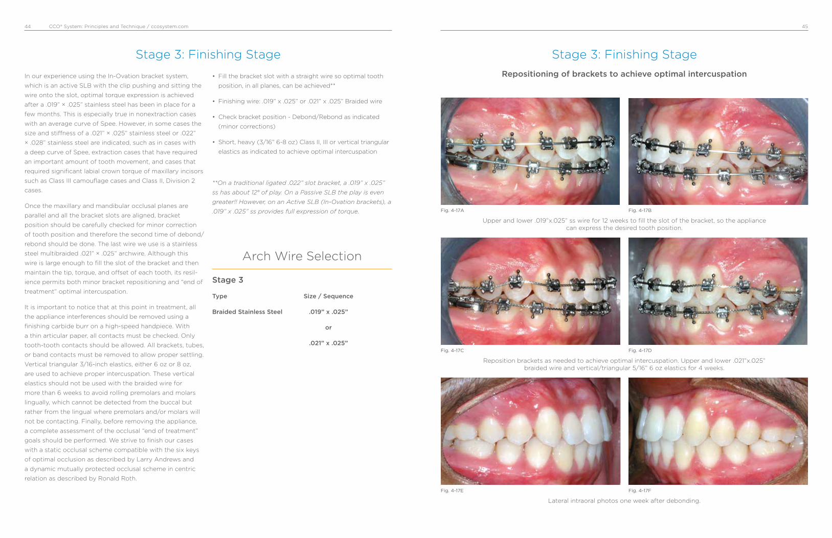
Repositioning of brackets to achieve optimal intercuspation
Upper and lower .019”x.025” ss wire for 12 weeks to fill the slot of the bracket, so the appliance can express the desired tooth position.
Reposition brackets as needed to achieve optimal intercuspation. Upper and lower .021”x.025” braided wire and vertical/triangular 5/16” 6 oz elastics for 4 weeks.
Lateral intraoral photos one week after debonding.
CCO® System: Principles and Technique / ccosystem.com 4746
Stage 3: Finishing Stage
Fig. 4-18A
Fig. 4-18C
Fig. 4-18E
Fig. 4-18B
Fig. 4-18D
Fig. 4-18F
Intermaxillary vertical elastics to achieve optimal intercuspation
Upper and lower .021”x.025” ss wire for 12 weeks to fill the slot of the bracket, so the appliance can express the desired tooth position.
Upper and lower .021”x.025” braided wire and vertical/triangular plus short Class II 5/16” 6 oz elastics left side for 4 weeks.
Lateral intraoral photos one weeks after debonding.
5. Clinical CaseThe objective of the following display of clinical cases
is to show step by step the correction of different types
of commonly found orthodontic problems in the adult
dentition. Emphasis is placed on the concepts of mechanics
previously discussed in this manual- such as stages of
treatment, wire sequence, etc. Specific mechanics for Class
III malocclusions, combined orthodontic/surgery treatment,
TADs, etc. will be discussed separately.
Case # 1: Class III, Non-extraction, no surgery, minimum/maximum anchorage.
Case # 2: Class I, Bimaxillary protrusion, severe mandibular crowding. Extractions UL 5’, medium anchorage.
Case # 3: Class II end on with upper right canine block out, extractions U4’/L5’, medium/minimum anchorage.
Case # 4: Class II end on, crowding and protrusion, extractions UL 4’, medium anchorage.
Case # 5: Class II end on with deep overbite. Non-extraction.
Case # 6: Class II end on with deep overbite. Non-extraction.
Case # 7: Class I with an open bite and posterior crossbite. Non-extraction.
Case # 8: Class II skeletal and dental with a narrow maxilla. Non-extraction.
Case # 9: Class I deep overbite and crowding. Non-extraction.
Case # 10: Class II right side with a deep overbite and increased curve of Spee. Midlines off. Non-extraction, molar distalization.
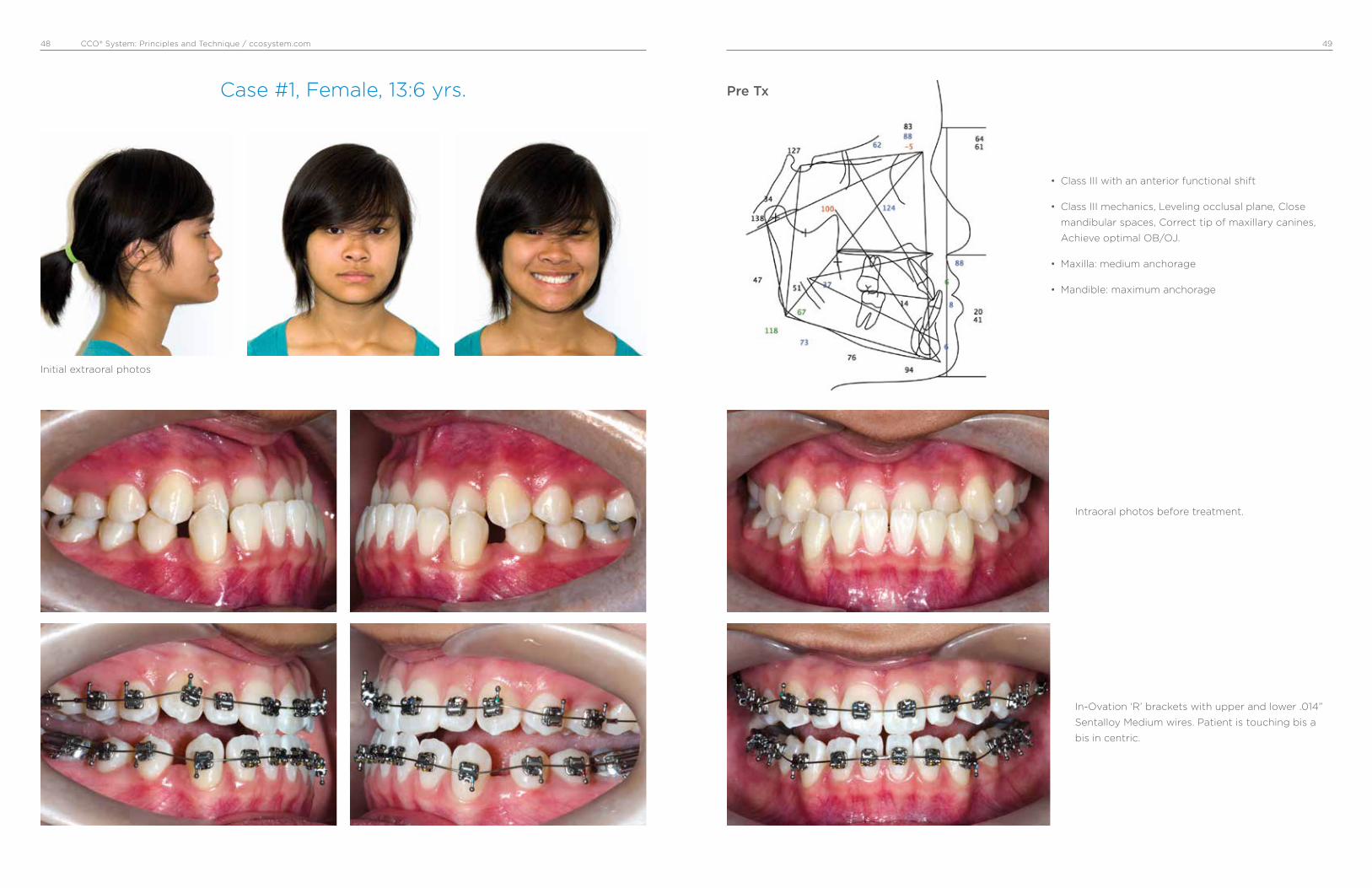
CCO® System: Principles and Technique / ccosystem.com 4948
Case #1, Female, 13:6 yrs.
• Class III with an anterior functional shift
• Class III mechanics, Leveling occlusal plane, Close
mandibular spaces, Correct tip of maxillary canines,
Achieve optimal OB/OJ.
• Maxilla: medium anchorage
• Mandible: maximum anchorage
Intraoral photos before treatment.
In-Ovation ‘R’ brackets with upper and lower .014”
Sentalloy Medium wires. Patient is touching bis a
bis in centric.
Pre Tx
Initial extraoral photos
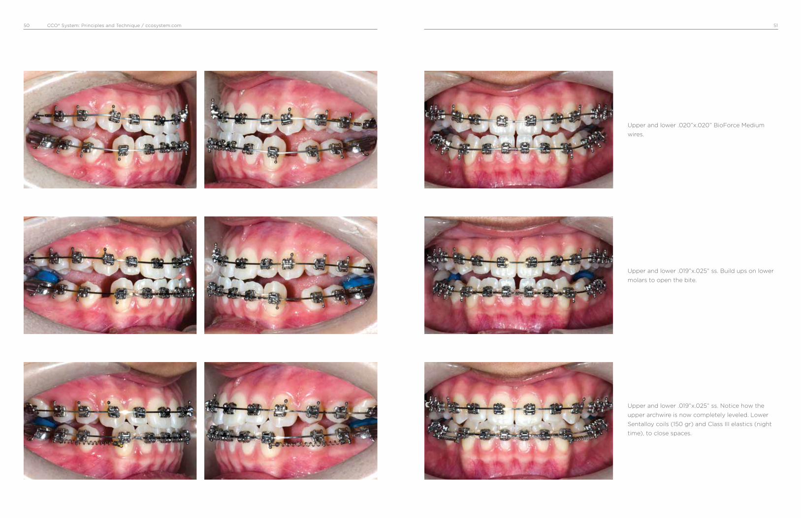
CCO® System: Principles and Technique / ccosystem.com 5150
Upper and lower .019”x.025” ss. Build ups on lower
molars to open the bite.
Upper and lower .020”x.020” BioForce Medium
wires.
Upper and lower .019”x.025” ss. Notice how the
upper archwire is now completely leveled. Lower
Sentalloy coils (150 gr) and Class III elastics (night
time), to close spaces.

CCO® System: Principles and Technique / ccosystem.com 5352
Spaces are consolidated. Good OJ/OB. triangular
elastics 3/16” 6 oz.
Upper and lower occlusal planes leveled and paral-
leled. Finishing space closure.
Upper .019”x.025” ss Braided wire and vertical trian-
gular 3/16” 6 or 8 oz.

CCO® System: Principles and Technique / ccosystem.com 5554
Intraoral final photos. 17 months of active Tx.
Pre Tx
Superimpositions
Post Tx
Before and After Smiles!

CCO® System: Principles and Technique / ccosystem.com 5756
Case #2, Female, 12:7 yrs.
• Class I with severe mandibular crowding
• Bimaxillary protrusion
• Extractions of UL5’
• Maxilla: medium anchorage
• Mandible: medium anchorage
Intraoral photos before treatment. Note protrusion
of maxillary teeth and position of lower canines.
Extraction of upper and lower second premolars.
In-Ovation R brackets and upper and lower .014”
Sentalloy Medium wires. Note the wire is engaged
in all the teeth with crimpable stops distal of
premolars.
Pre Tx
Initial extraoral photos

CCO® System: Principles and Technique / ccosystem.com 5958
Upper and lower .020”x.020” BioForce Med. Notice
leveling and aligning, no elastics or auxiliaries have
been used.
Upper and lower .018 Sentalloy Med.
Upper and lower .019” x .025” ss coordinated wires.
Beginning of working stage.

CCO® System: Principles and Technique / ccosystem.com 6160
Note mesial movement of mandibular molars.
Maintained OJ and OB.
Sentalloy coil (150 g) attached from lower first
molar to crimpable hook placed distal of canines.
3/16” 4 oz. short Class II elastics at nighttime.
Extraction spaces are closed. Sentalloy coils do not
need to be activated. They maintain their activation
throughout the treatment.

CCO® System: Principles and Technique / ccosystem.com 6362
Upper .021”x .025” Braided wire with triangular
vertical elastics to achieve proper intercuspation.
Same working wires as previous photos. C-chain
upper and lower arch to consolidate spaces.
Intraoral final photos. 23 months of active Tx.
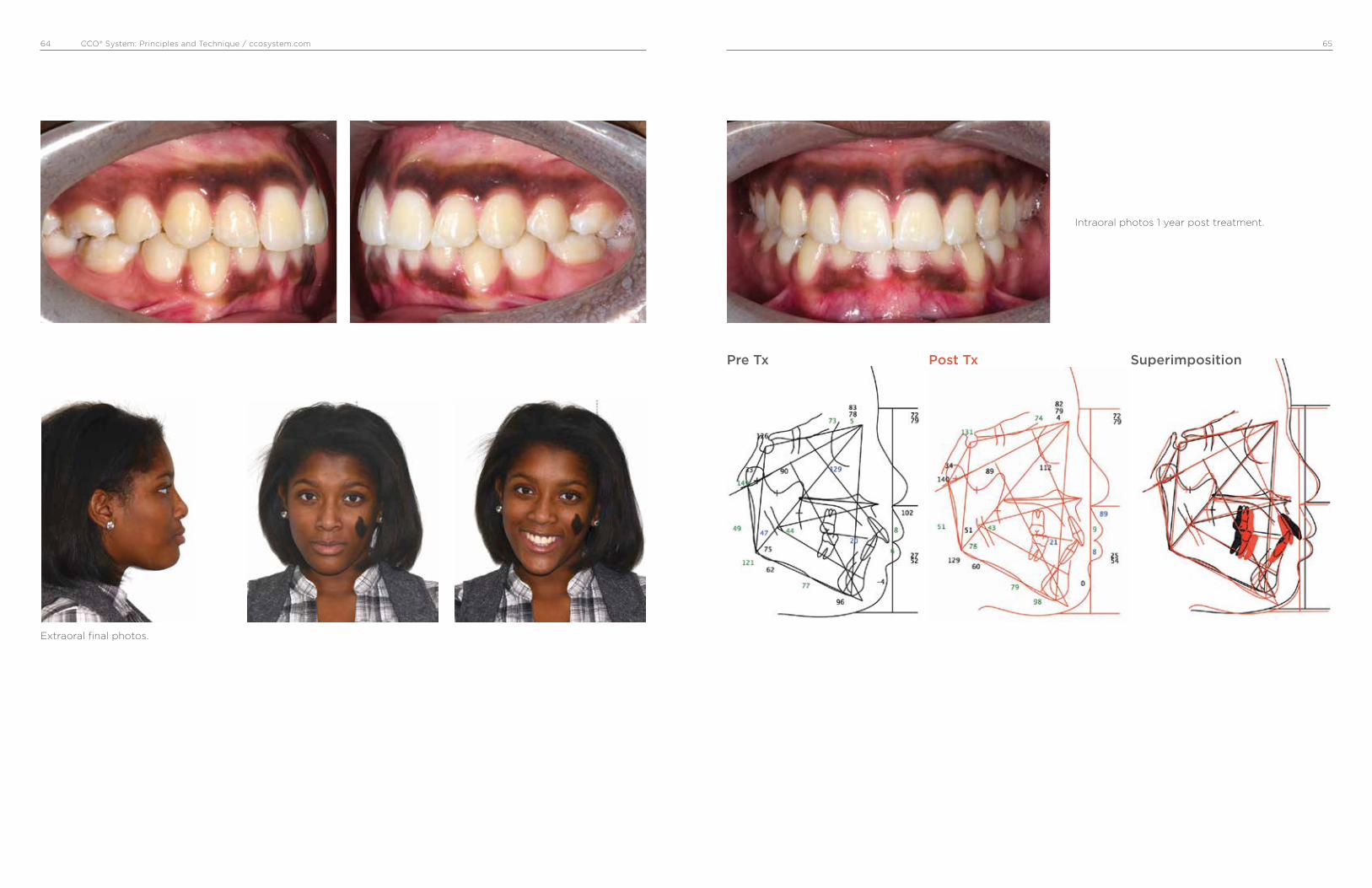
CCO® System: Principles and Technique / ccosystem.com 6564
Intraoral photos 1 year post treatment.
Pre Tx Post Tx Superimposition
Extraoral final photos.

CCO® System: Principles and Technique / ccosystem.com 6766
Case #3, Male, 14:03 yrs.
• Class II end-on right and left side.
• Upper right canine blocked out.
• Upper midline deviated to patient’s right
• Extractions of U4’ and L5’
• Maxilla: medium anchorage
• Mandible: minimum anchorage
Intraoral photos before treatment.
Extraction of upper 4’ and lower 5’. In-Ovation R
brackets and upper and lower .014” Sentalloy
Medium wires.
Pre Tx
Initial extraoral photos
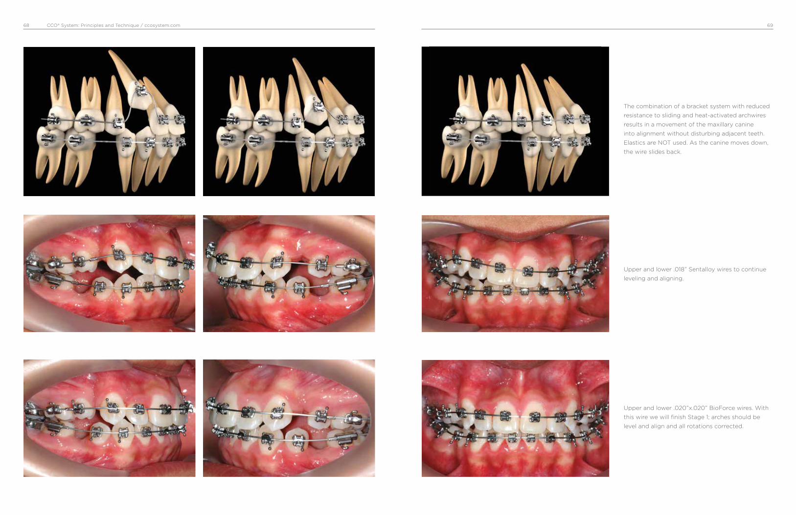
CCO® System: Principles and Technique / ccosystem.com 6968
Upper and lower .018” Sentalloy wires to continue
leveling and aligning.
The combination of a bracket system with reduced
resistance to sliding and heat-activated archwires
results in a movement of the maxillary canine
into alignment without disturbing adjacent teeth.
Elastics are NOT used. As the canine moves down,
the wire slides back.
Upper and lower .020”x.020” BioForce wires. With
this wire we will finish Stage 1; arches should be
level and align and all rotations corrected.

CCO® System: Principles and Technique / ccosystem.com 7170
Continuous with DKH activation. Notice how first
molars are moving forward to a Class I.
Stage 2, upper .019”x .025” ss and lower .021”x.025”
DKH activated with a ss ligature from first molar
for minimum anchorage. Patient was asked to wear
short Class II 3/16” 4 oz elastics at night.
After spaces are closed, upper and lower
.021”x .025” ss wire with triangular vertical 6 oz
elastics to finish flattening the occlusal plane.

CCO® System: Principles and Technique / ccosystem.com 7372
Intraoral final photos. 20 months of active Tx.
Upper and lower .021”x.025” Braided wire with
triangular vertical 6 oz elastics to detail the
occlusion.
Extraoral final photos.
Pre Tx Post Tx Superimposition
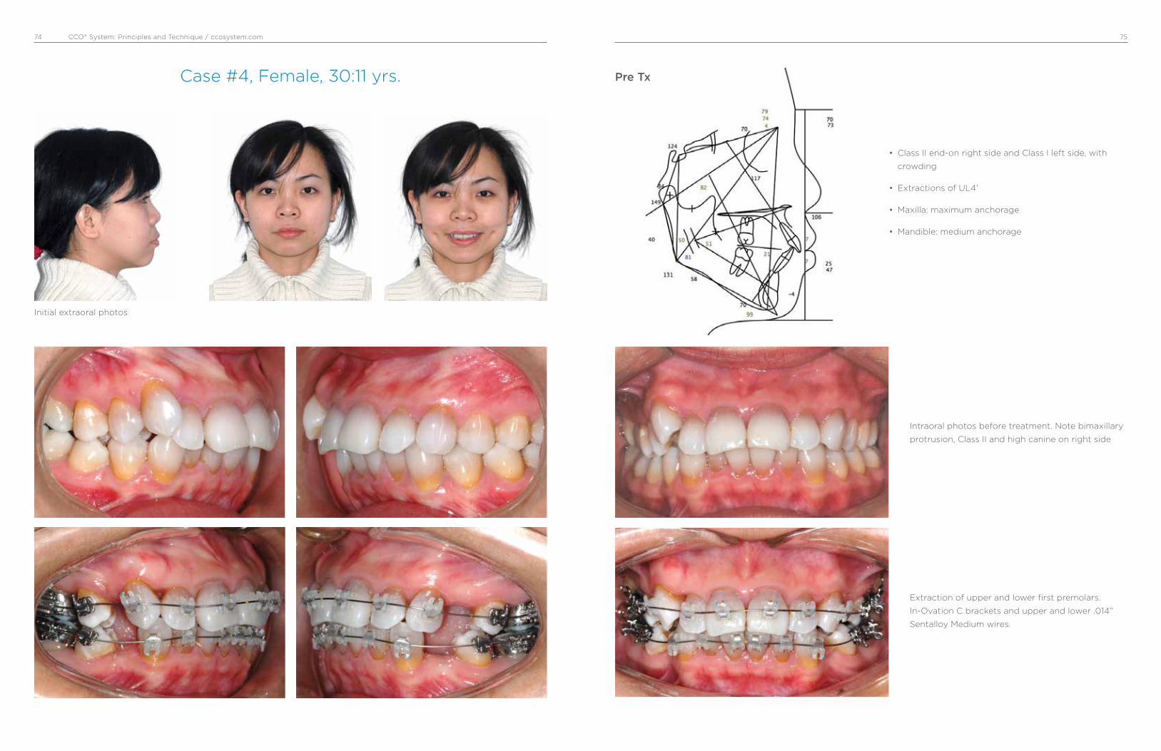
CCO® System: Principles and Technique / ccosystem.com 7574
Case #4, Female, 30:11 yrs.
• Class II end-on right side and Class I left side, with
crowding
• Extractions of UL4’
• Maxilla: maximum anchorage
• Mandible: medium anchorage
Intraoral photos before treatment. Note bimaxillary
protrusion, Class II and high canine on right side
Extraction of upper and lower first premolars.
In-Ovation C brackets and upper and lower .014”
Sentalloy Medium wires.
Pre Tx
Initial extraoral photos

CCO® System: Principles and Technique / ccosystem.com 7776
Upper .019”x.025” ss and lower .019”x.025” ss with
crimpable hooks. Sentalloy coils (150 g) are used to
close mandibular spaces.
Remaining spaces were closed with C-chain and
short Class II 6 oz elastics.
Upper .018” Sentalloy to preserve anchorage and
lower .020”x.020” BioForce Medium wires. Note
uprighting of maxillary and mandibular incisors,
reduction of extraction spaces, maintained molar
relationship and improved canine relationship.

CCO® System: Principles and Technique / ccosystem.com 7978
Upper and lower .021”x.025” Braided wire with
triangular vertical 6 oz elastics to detail the
occlusion.
Upper and lower .021”x.025” ss wires to express
torque and flatten occlusal plane. Continue with
short Class II 6 oz elastics.
Intraoral final photos. 23 months of active Tx.

CCO® System: Principles and Technique / ccosystem.com 8180
Extraoral final photos.
Intraoral photos 3 years post Tx.
Pre Tx Post Tx Superimposition
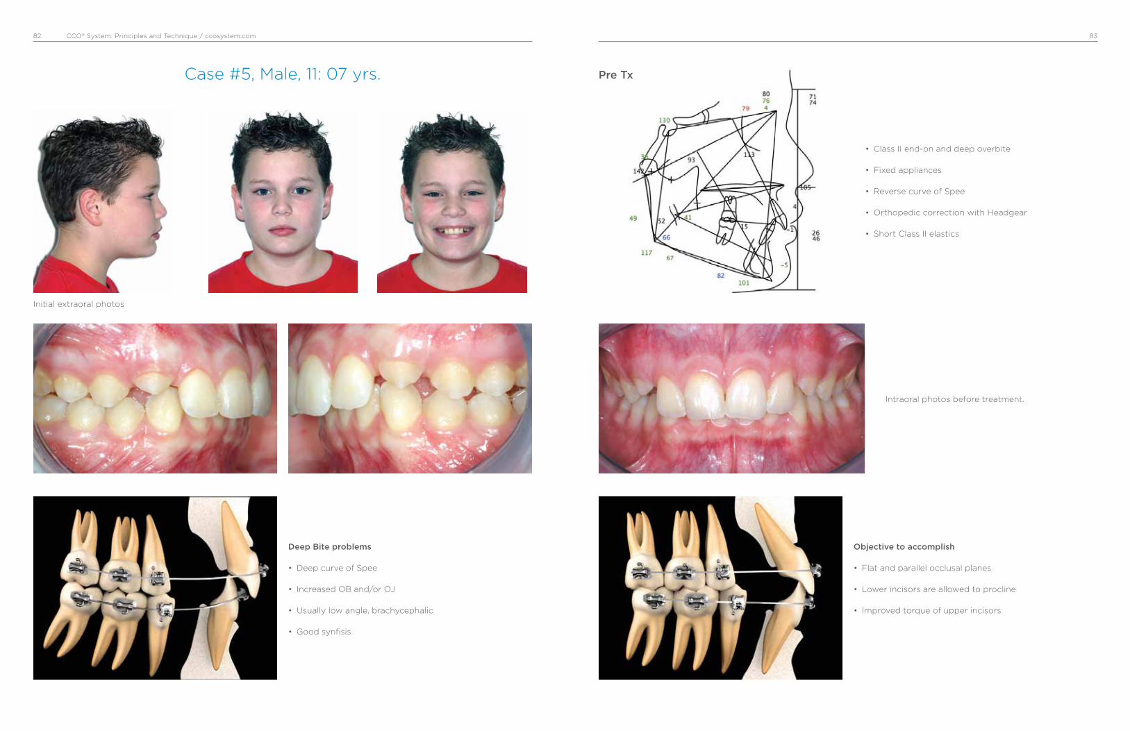
CCO® System: Principles and Technique / ccosystem.com 8382
Case #5, Male, 11: 07 yrs.
• Class II end-on and deep overbite
• Fixed appliances
• Reverse curve of Spee
• Orthopedic correction with Headgear
• Short Class II elastics
Deep Bite problems
• Deep curve of Spee
• Increased OB and/or OJ
• Usually low angle, brachycephalic
• Good synfisis
Objective to accomplish
• Flat and parallel occlusal planes
• Lower incisors are allowed to procline
• Improved torque of upper incisors
Intraoral photos before treatment.
Pre Tx
Initial extraoral photos
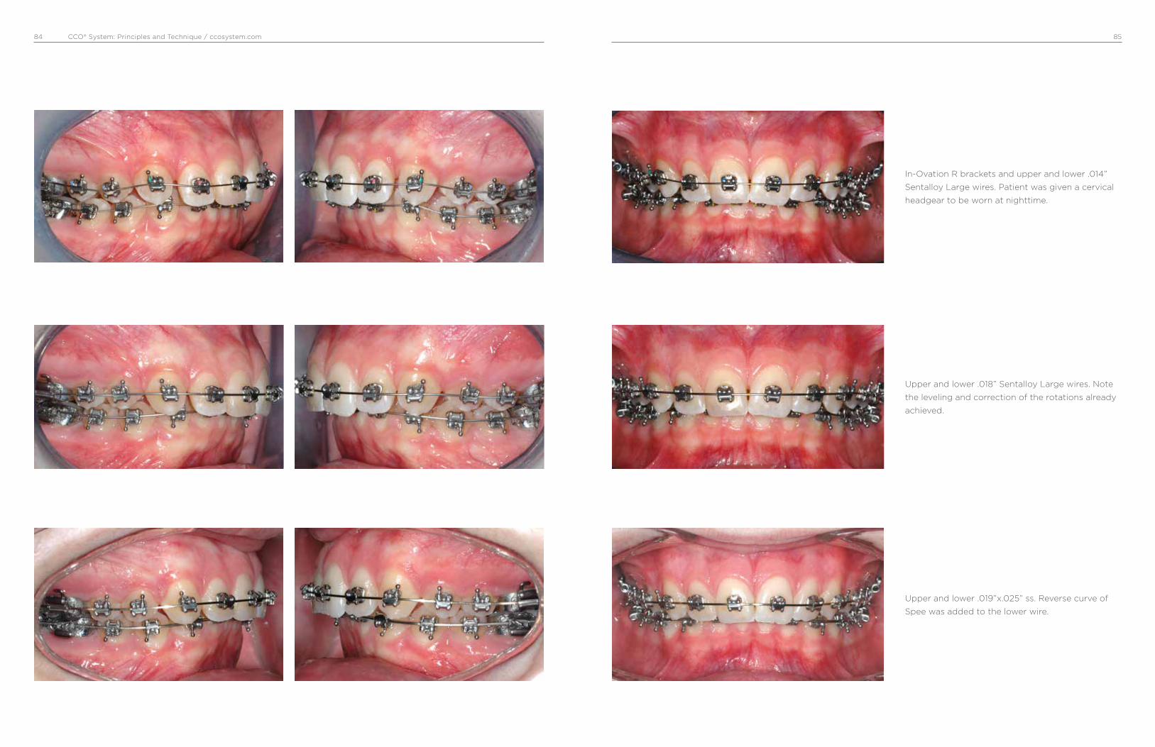
CCO® System: Principles and Technique / ccosystem.com 8584
Upper and lower .018” Sentalloy Large wires. Note
the leveling and correction of the rotations already
achieved.
Upper and lower .019”x.025” ss. Reverse curve of
Spee was added to the lower wire.
In-Ovation R brackets and upper and lower .014”
Sentalloy Large wires. Patient was given a cervical
headgear to be worn at nighttime.
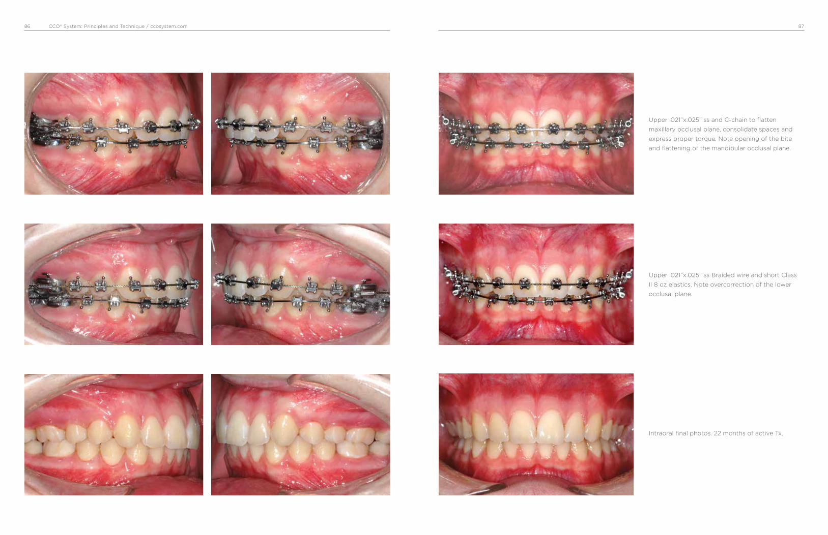
CCO® System: Principles and Technique / ccosystem.com 8786
Upper .021”x.025” ss Braided wire and short Class
II 8 oz elastics. Note overcorrection of the lower
occlusal plane.
Upper .021”x.025” ss and C-chain to flatten
maxillary occlusal plane, consolidate spaces and
express proper torque. Note opening of the bite
and flattening of the mandibular occlusal plane.
Intraoral final photos. 22 months of active Tx.
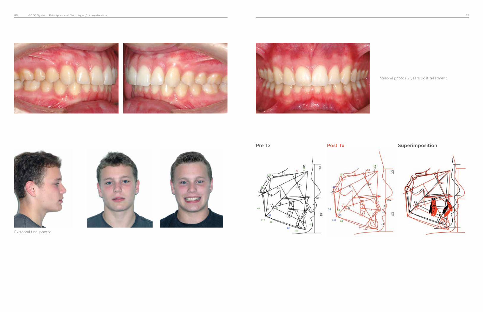
CCO® System: Principles and Technique / ccosystem.com 8988
Extraoral final photos.
Intraoral photos 2 years post treatment.
Pre Tx Post Tx Superimposition
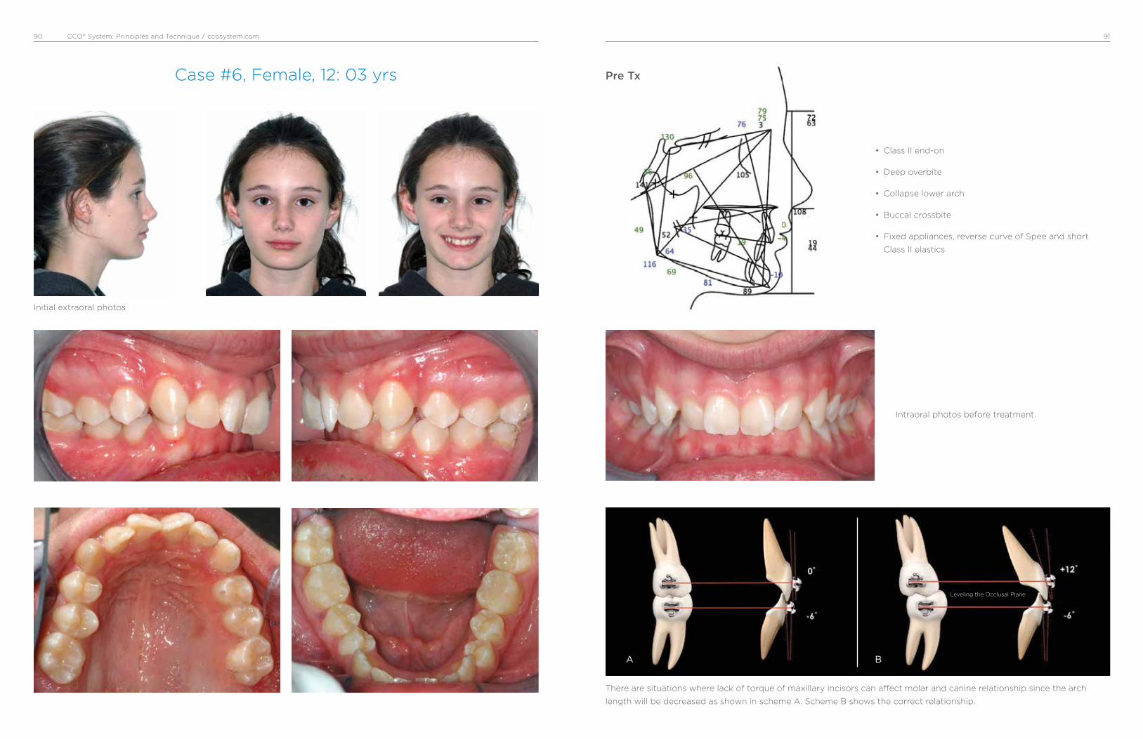
CCO® System: Principles and Technique / ccosystem.com 9190
Case #6, Female, 12: 03 yrs
• Class II end-on
• Deep overbite
• Collapse lower arch
• Buccal crossbite
• Fixed appliances, reverse curve of Spee and short
Class II elastics
Intraoral photos before treatment.
There are situations where lack of torque of maxillary incisors can affect molar and canine relationship since the arch
length will be decreased as shown in scheme A. Scheme B shows the correct relationship.
Pre Tx
Leveling the Occlusal Plane
A B
Initial extraoral photos

CCO® System: Principles and Technique / ccosystem.com 9392
Upper .020”x .020” BioForce Medium wires.
Upper .019”x.025” ss. Lower In-Ovation R appliance
and a .014” Sentalloy Medium wire. Mandibular
molars were built up with composite to temporarily
open the bite.
In-Ovation R brackets and upper .014” Sentalloy
Med wires. Upper arch was bonded first to level and
align and to create space for the lower appliance.

CCO® System: Principles and Technique / ccosystem.com 9594
Improvement of Class I molar and canine, occlusal
planes begin to flatten.
Lower .019”x.025” ss with reverse curve of Spee and
C-chain from canine to canine to prevent opening
spaces. Class II short 6 oz elastics.
Upper and lower .021” x .025” ss and Class II short 6
oz elastics.

CCO® System: Principles and Technique / ccosystem.com 9796
Upper .021” x .025” ss Braided wire and
triangular vertical 6 oz elastics to finish and detail
the occlusion.
Good Class I molar and canine has been achieved
and occlusal planes are parallel.
Intraoral final photos. 27 months of active Tx.
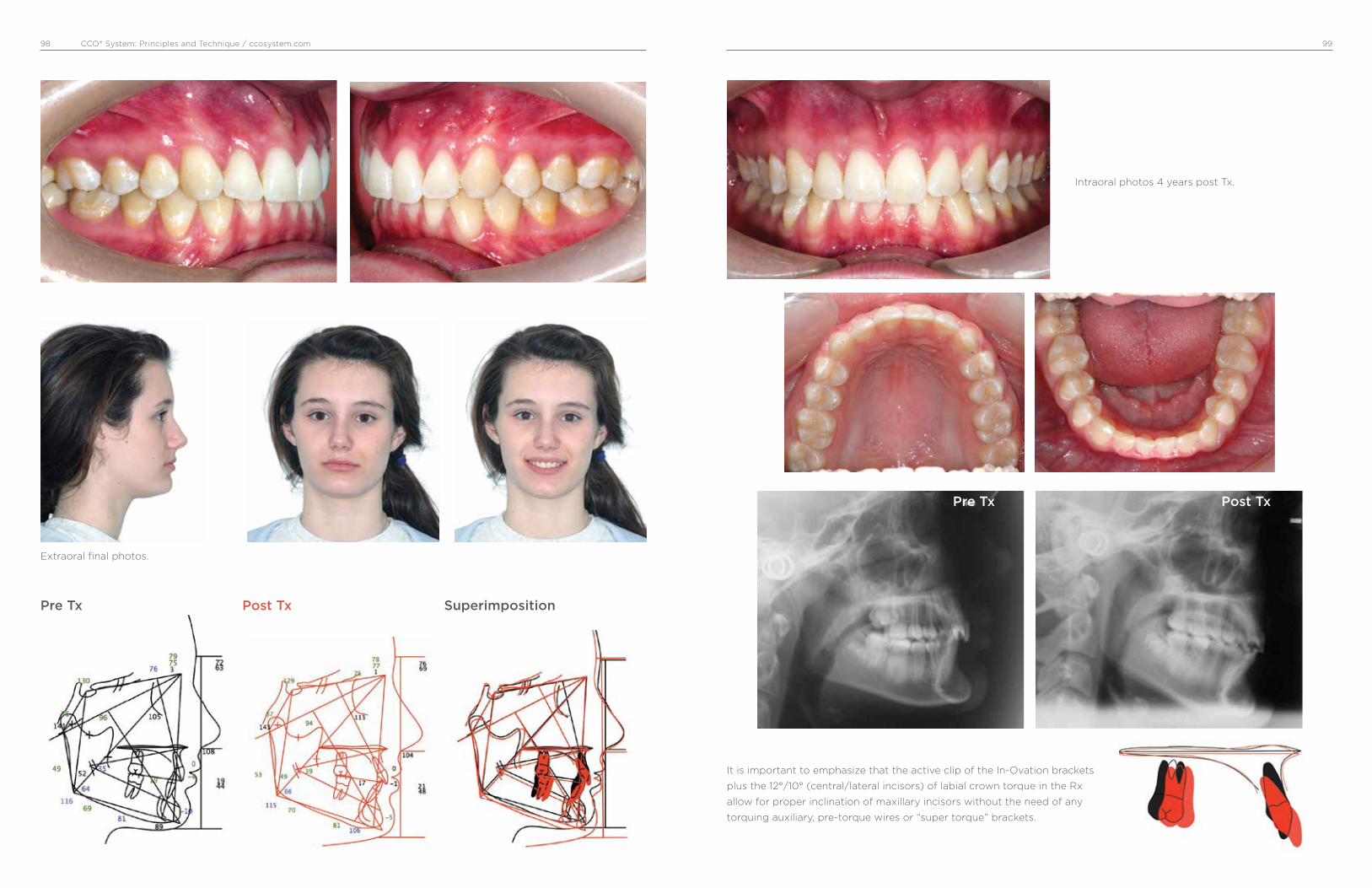
CCO® System: Principles and Technique / ccosystem.com 9998
Extraoral final photos.
Intraoral photos 4 years post Tx.
It is important to emphasize that the active clip of the In-Ovation brackets
plus the 12°/10° (central/lateral incisors) of labial crown torque in the Rx
allow for proper inclination of maxillary incisors without the need of any
torquing auxiliary, pre-torque wires or “super torque” brackets.
Pre Tx Post Tx Superimposition
Pre Tx Post Tx

CCO® System: Principles and Technique / ccosystem.com 101100
Case #7, Female, 20: 05 yrs
• Class I open bite
• Posterior unilateral crossbite
• Fixed appliances, transpalatal bars for vertical control
and arch coordination
Solution
Low deflection thermal-activated wires do not
overcome occlusal forces, and posterior teeth do
not extrude. Then, as the occlusal planes flatten
and parallel, the open bite closes.
Problems
Open bite pattern
Divergent occlusal planes
Usually narrow and long synfisis
Pre Tx
Initial extraoral photos
Intraoral photos before treatment.
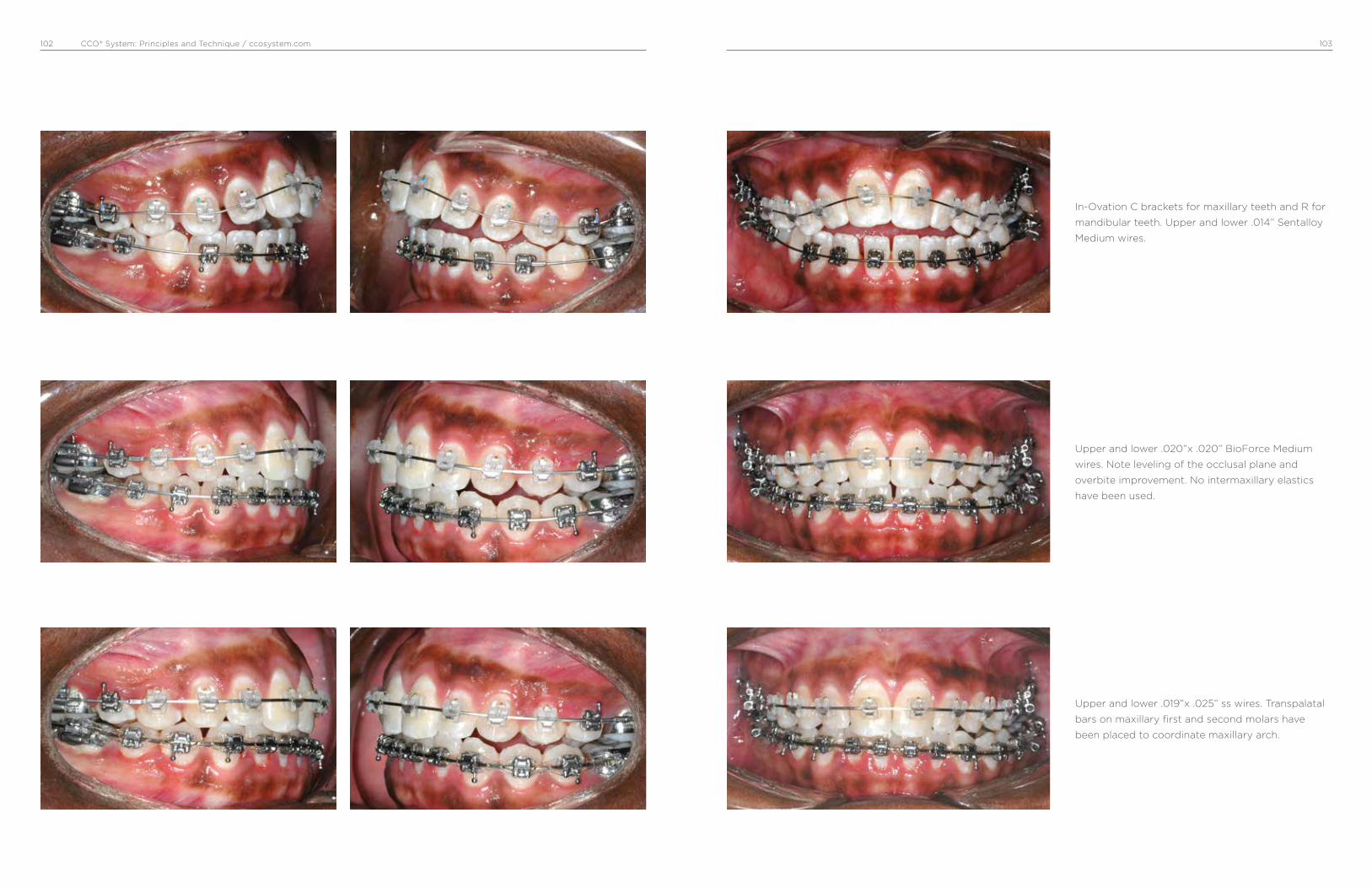
CCO® System: Principles and Technique / ccosystem.com 103102
Upper and lower .020”x .020” BioForce Medium
wires. Note leveling of the occlusal plane and
overbite improvement. No intermaxillary elastics
have been used.
Upper and lower .019”x .025” ss wires. Transpalatal
bars on maxillary first and second molars have
been placed to coordinate maxillary arch.
In-Ovation C brackets for maxillary teeth and R for
mandibular teeth. Upper and lower .014” Sentalloy
Medium wires.

CCO® System: Principles and Technique / ccosystem.com 105104
Posterior arch coordination has been achieved.
Vertical triangular elastics 6 oz are used to level the
occlusal plane. Note how the bite has been closed
to a better overbite.
The bite opens temporarily while the upper arch is
dentally expanded with transpalatal bars.
Upper and lower .021”x .025” ss wires and triangular
vertical 6 oz elastics.
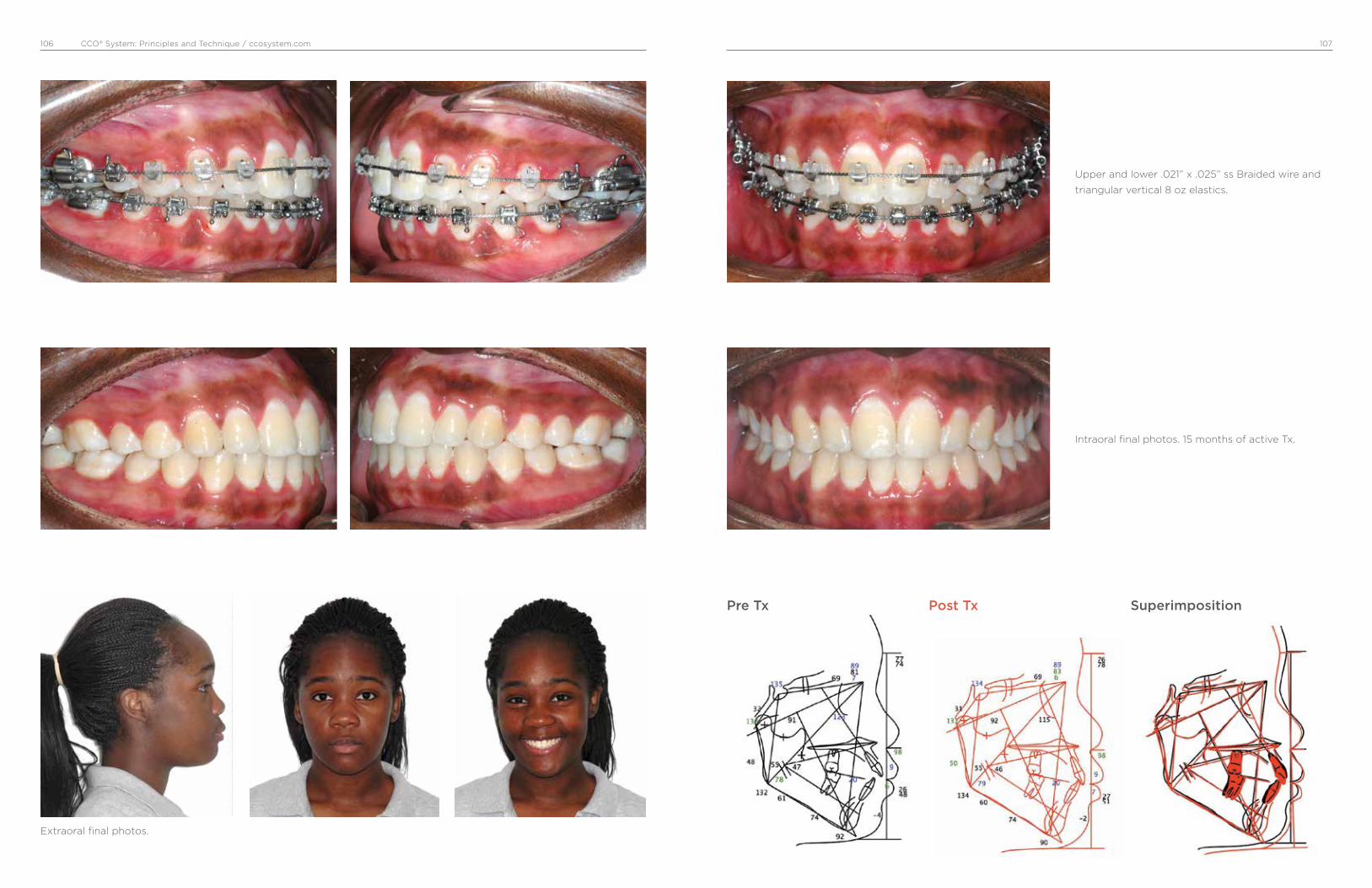
CCO® System: Principles and Technique / ccosystem.com 107106
Extraoral final photos.
Pre Tx Post Tx Superimposition
Upper and lower .021” x .025” ss Braided wire and
triangular vertical 8 oz elastics.
Intraoral final photos. 15 months of active Tx.

CCO® System: Principles and Technique / ccosystem.com 109108
Case #8, Male, 13: 03 yrs.
Maxillary Haas-type expander in place. After two weeks of rapid maxillary expansion (two turns per day).
• Class II dental and skeletal.
• Narrow maxilla.
• RPE, fixed appliances, HPHG and short Class II elastics.
Pre Tx
Initial extraoral photos
Intraoral photos before treatment. Note Class II and
deep overbite.
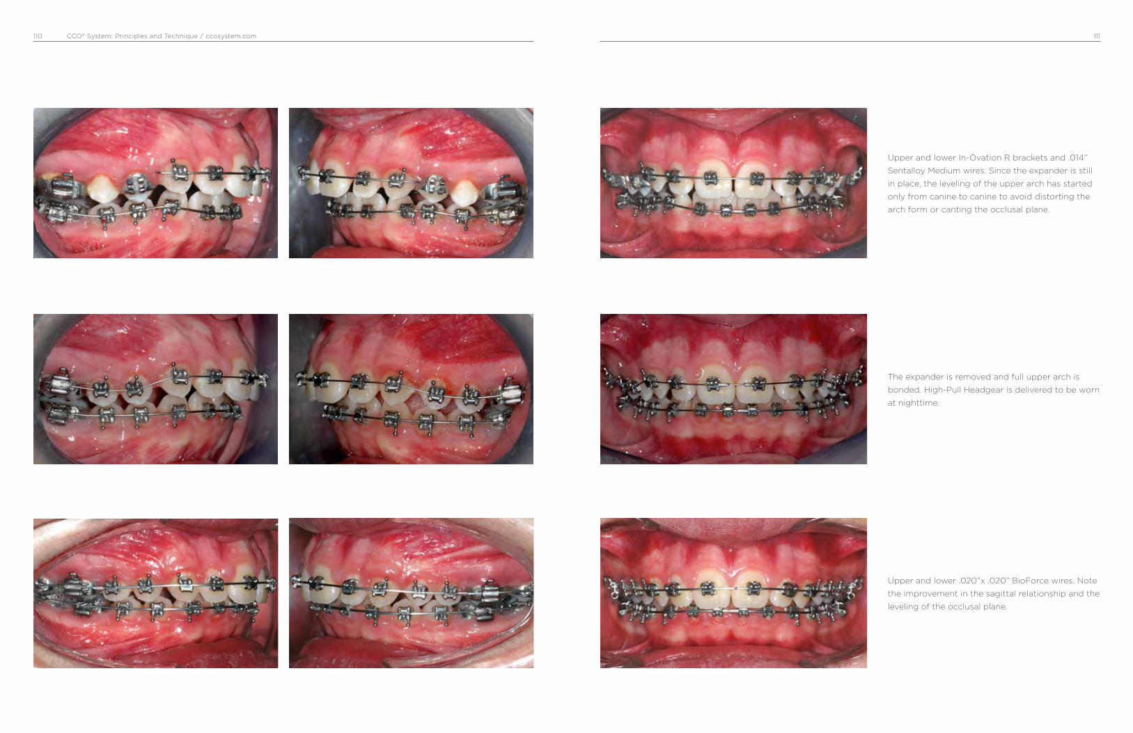
CCO® System: Principles and Technique / ccosystem.com 111110
The expander is removed and full upper arch is
bonded. High-Pull Headgear is delivered to be worn
at nighttime.
Upper and lower .020”x .020” BioForce wires. Note
the improvement in the sagittal relationship and the
leveling of the occlusal plane.
Upper and lower In-Ovation R brackets and .014”
Sentalloy Medium wires. Since the expander is still
in place, the leveling of the upper arch has started
only from canine to canine to avoid distorting the
arch form or canting the occlusal plane.
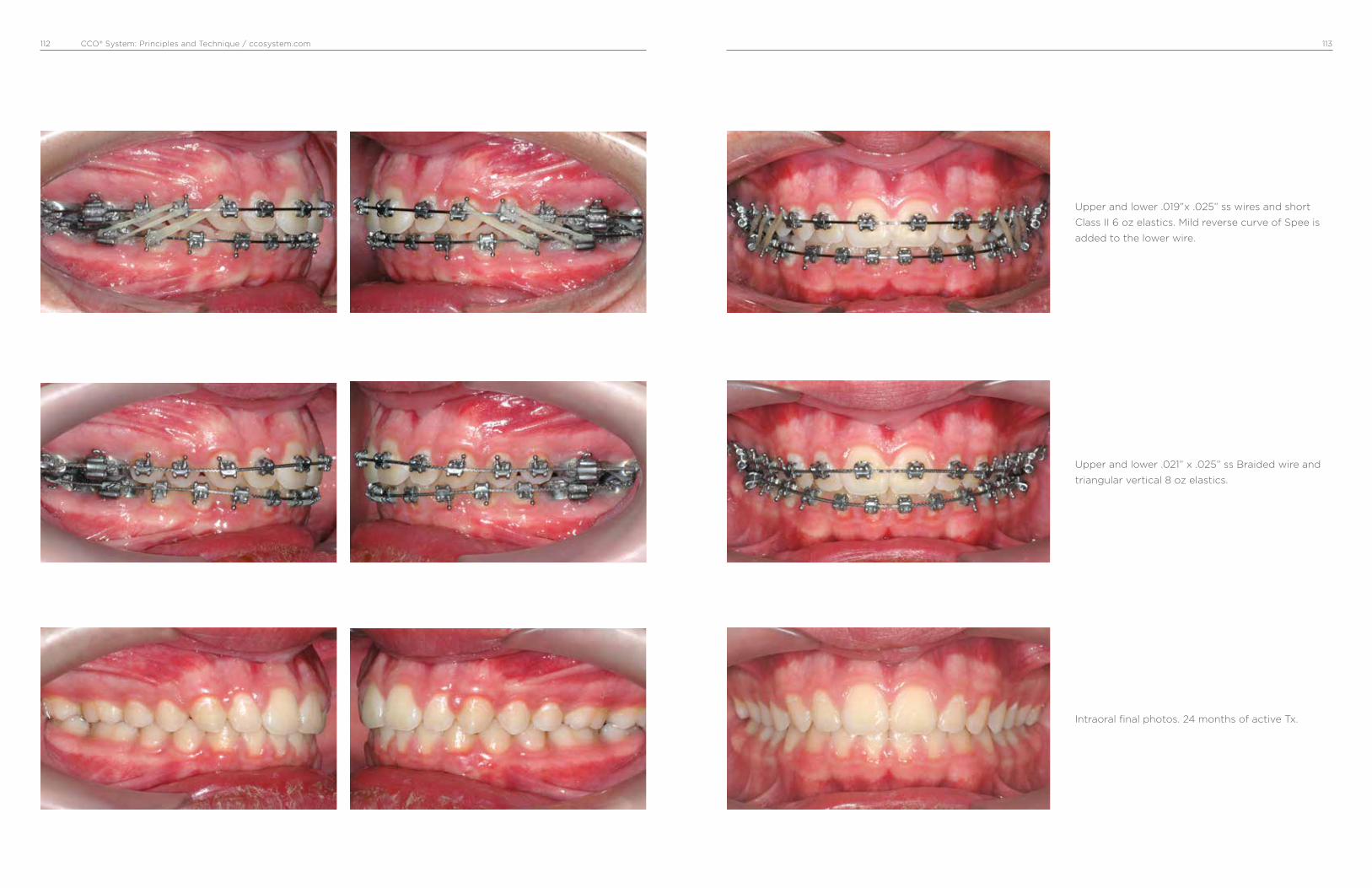
CCO® System: Principles and Technique / ccosystem.com 113112
Upper and lower .021” x .025” ss Braided wire and
triangular vertical 8 oz elastics.
Upper and lower .019”x .025” ss wires and short
Class II 6 oz elastics. Mild reverse curve of Spee is
added to the lower wire.
Intraoral final photos. 24 months of active Tx.

CCO® System: Principles and Technique / ccosystem.com 115114
Extraoral final photos.
Pre Tx Post Tx Superimposition
Intraoral photos 2 years post treatment.

CCO® System: Principles and Technique / ccosystem.com 117116
Case #9, Male, 11: 10 yrs
• Class I with increased overbite and crowding of lower
incisors.
• Fixed appliances and TPB.
Pre Tx
Initial extraoral photos
Intraoral photos before treatment. Note deep
overbite.
Upper and lower In-Ovation R brackets and .014”
Sentalloy Medium wires for initial leveling and
alignment. Upper wire was covered with a plastic
tubing between lateral incisors and first molar.
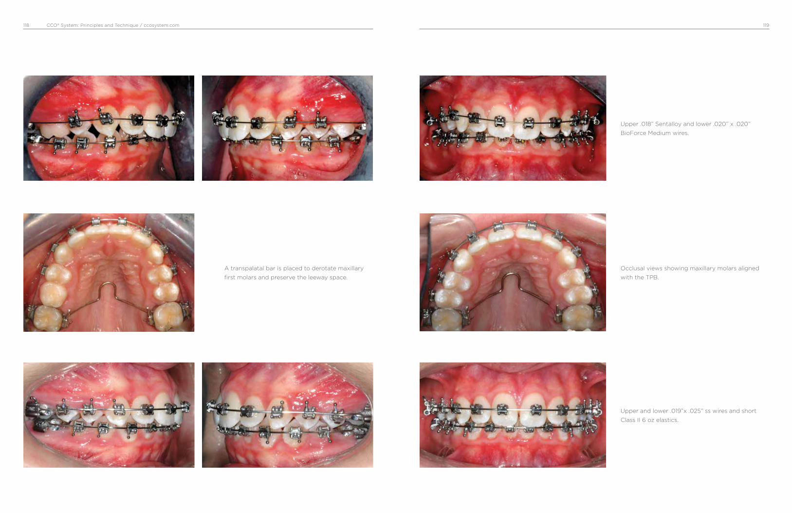
CCO® System: Principles and Technique / ccosystem.com 119118
Occlusal views showing maxillary molars aligned
with the TPB.
A transpalatal bar is placed to derotate maxillary
first molars and preserve the leeway space.
Upper and lower .019”x .025” ss wires and short
Class II 6 oz elastics.
Upper .018” Sentalloy and lower .020” x .020”
BioForce Medium wires.

CCO® System: Principles and Technique / ccosystem.com120
Upper and lower .021” x .025” Braided wire. Vertical
triangular 6 oz elastics to achieve optimal intercus-
pation.
Upper and lower .021” x .025” ss wire. C-chain to
consolidate spaces and short Class II 6 oz elastics.
Intraoral final photos.

CCO® System: Principles and Technique / ccosystem.com 123122
Extraoral final photos.
Pre Tx Post Tx Superimposition
Pictures A, B and C showing lower occlusal view
before tx (A), midcourse tx (B), and after tx (C).
Note correction of crowding.
Intraoral photos 2 years post treatment.
A B C
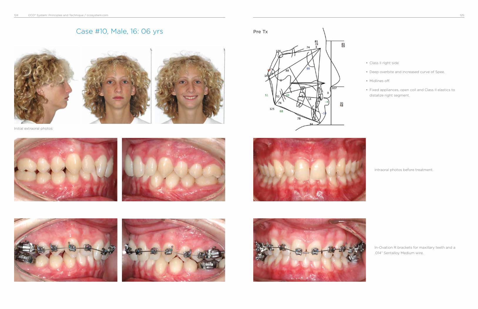
CCO® System: Principles and Technique / ccosystem.com 125124
Case #10, Male, 16: 06 yrs
Initial extraoral photos
• Class II right side
• Deep overbite and increased curve of Spee.
• Midlines off.
• Fixed appliances, open coil and Class II elastics to
distalize right segment.
Pre Tx
Intraoral photos before treatment.
In-Ovation R brackets for maxillary teeth and a
.014” Sentalloy Medium wire.

CCO® System: Principles and Technique / ccosystem.com 127126
Lower .019”x .025” ss, open coil between upper
right first molar and second premolar. Short Class
II 3/16” 4 oz from upper canine to lower second
premolar.
Upper .020”x .020” BioForce Medium wires.
Upper .019”x .025” ss and lower .020”x .020”
BioForce wires. Biturbos bonded on the palatal
surface of upper central incisors were used to open
the bite temporarily.

CCO® System: Principles and Technique / ccosystem.com 129128
Upper first and second premolars have been
distalized and now one open coil has been placed
between canine and first premolar. Continues with
short Class II elastics.
Upper right first and second molars have been
distalized to a Class I. Open coil has been moved
between first and second premolars. Continues
with short Class II elastics.
Upper and lower .021” x .025” ss wires to provide
proper torque and flatten occlusal plane. Elasto-
meric chain to consolidate remaining spaces. Right
side a short Class II and left side a triangular vertical
3/16” 6 oz elastic.

CCO® System: Principles and Technique / ccosystem.com 131130
Extraoral final photos.
Pre Tx Post Tx Superimposition
Intraoral final photos. 26 months of active Tx.
Upper .021” x .025” ss Braided and lower .021” x
.025” ss wires; right and left side with triangular
vertical 3/16” 6 oz elastics.

CCO® System: Principles and Technique / ccosystem.com132
Dr. Antonino Secchi Dr. Secchi maintains a private practice
in Devon, PA. He is a Diplomate of
the American Board of Orthodontics
and member of the Edward H. Angle
Society of Orthodontists.
Dr. Secchi received his DMD, Certif-
icate in Orthodontics, and a Master
of Science in Oral Biology from the
University of Pennsylvania, same
institution where he taught for
over 10 years holding the position
of Clinical Assistant Professor and
Clinical Director of the Department of
Orthodontics.
Dr. Secchi has published in various
dental and orthodontic peer review
journals in the areas of treatment
mechanics and the straight wire
appliance. He wrote the chapter
“Contemporary Mechanics Using
the Straight Wire Appliance” for
the last two editions of the Graber/
Vanarsdall/Vig orthodontic textbook.
Dr. Secchi received the 2005 David
C. Hamilton Orthodontic Research
Award from the Pennsylvania
Association of Orthodontists (PAO)
and the 2010 and 2013 Outstanding
Teacher Award from the Department
of Orthodontics of the University of
Pennsylvania.
Dr. Secchi is the founder of the
“Complete Clinical Orthodontics
System” (CCO System™) and the
Secchi Institute™, which provides
continuing education for orthodon-
tists in the USA as well as throughout
the world.
Dr. Secchi loves to spend time with
his wife and 5 children. He is a
passionate photographer and likes
people, traveling and sports.

0280-MM-120-057-04 Rev. 05
© 2017 Dentsply SironaAll Rights Reserved.
800.645.5530www.dentsplysirona.com/orthodontics
Antonino G. Secchi DMD, MS
Principles and Technique
www.ccosystem.com
Complete Clinical Orthodontics®
CCO® System
Academy
*+D807120057041/$$720171201D*