The Study on the Hierarchy of Internet Router-Level Topology
description


Lab 1.1.2 OSI Model review – Overview
E1E0
S1
E0
S1
E0
S1
E0 E0
S0(DCE)
S0(DCE)
192.5.5.0 net
219.17.100.0 net 223.8.151.0 net
210.93.105.0 net
204.204.7.0 net199.6.13.0 net
201.100.11.0 net
205.7.5.0 net
S0(DCE)Lab_A
Lab_B
Lab_C
Lab_D Lab_E
Router Name - Lab_ARouter Type - 2514E0 = 192.5.5.1E1 = 205.7.5.1S0 = 201.100.11.1SM = 255.255.255.0
Router Name - Lab_BRouter Type - 2501E0 = 219.17.100.1S0 = 199.6.13.1S1 = 201.100.11.2SM = 255.255.255.0
Router Name - Lab_CRouter Type - 2501E0 = 223.8.151.1S0 = 204.204.7.1S1 = 199.6.13.2SM = 255.255.255.0
Router Name - Lab_DRouter Type - 2501E0 = 210.93.105.1S1 = 204.204.7.2SM = 255.255.255.0
Router Name - Lab_ERouter Type - 2501E0 = 210.93.105.2SM = 255.255.255.0
Router Lab Topology
Estimated time: 20 min.
Objectives:
• Match devices and terminology to the various layers of the OSI model • Match OSI layers with those of the TCP/IP model • Identify TCP/IP protocols and utilities that operate at each layer
Background:
This lab will serve as a refresher to reinforce understanding of the seven layers of the OSI model as they relate to the TCP/IP model. Focus is on where terms and devices fit in the OSI model. This lab can be a fun collaborative knowledge competition activity.

Tools / Preparation:
Create a group competition! Count off and divide into teams of 2 to 4 people each. Without looking at your notes or answers, see how accurately your team can fill in the OSI table in the worksheet. The team with the most correct entries (points) in the table at the end of the specified time (e.g. 10 min.) wins. If another team questions a term or table entry, they may challenge and receive the points if agreed upon by the review committee (made up of one member from each team).
Before beginning this lab you should read the Networking Academy Second Year Companion Guide, Chapter 1 and chapters 1, 9 and 10 of the First year Companion guide. You should also review semester 3 on-line Lesson 1. The following resources will be required:
• PC workstation with Windows installed • NIC installed and Cat 5 patch cable with connection to the Internet • Browser software installed (Netscape Navigator 3.0 or higher or Internet
Explorer 4.0 or higher) • Sample networking items such as Ethernet and Token Ring NICs with
different connectors (Coax, AUI, RJ-45) • Sample Hubs, Switches and Routers
Notes:
Step 1 – The OSI model and associated TCP/IP protocol stack layers.
Task: Fill out the following chart based on your knowledge of the OSI and TCP/IP models. Explanation: Your understanding of the OSI model as it relates to the TCP/IP model will greatly increase your ability to absorb and categorize networking information as you learn it.
1. Given the OSI layer number fill in the chart below. Compete with other teams if possible and try to think of as many protocols, standards, utilities, terms and devices as possible without looking at your notes. Note: TCP/IP layers will relate to more than one OSI layer.

2.
OSI model and TCP/IP Protocol Stack
OSI # OSI Layer Name (and function)
TCP/ IP #
TCP/IP Layer name
Protocols, standards & utilities at each TCP/IP layer
Devices and Terms associated with this layer
7
6
5
4
3
2
1

Lab 1.5.13.1 Router lab setup review- Overview
E1E0
S1
E0
S1
E0
S1
E0 E0
S0(DCE)
S0(DCE)
192.5.5.0 net
219.17.100.0 net 223.8.151.0 net
210.93.105.0 net
204.204.7.0 net199.6.13.0
net
201.100.11.0 net
205.7.5.0 net
S0(DCE)Lab_A
Lab_B
Lab_C
Lab_D Lab_E
Router Name - Lab_ARouter Type - 2514E0 = 192.5.5.1E1 = 205.7.5.1S0 = 201.100.11.1SM = 255.255.255.0
Router Name - Lab_BRouter Type - 2501E0 = 219.17.100.1S0 = 199.6.13.1S1 = 201.100.11.2SM = 255.255.255.0
Router Name - Lab_CRouter Type - 2501E0 = 223.8.151.1S0 = 204.204.7.1S1 = 199.6.13.2SM = 255.255.255.0
Router Name - Lab_DRouter Type - 2501E0 = 210.93.105.1S1 = 204.204.7.2SM = 255.255.255.0
Router Name - Lab_ERouter Type - 2501E0 = 210.93.105.2SM = 255.255.255.0
Router Lab Topology
Estimated Time: 30 min.
Objectives:
• Setup the Cisco lab equipment according to the semester 2 topologydiagram shown above or analyze the physical connections of an existinglab setup.
• Document the cabling and connections between devices
• Draw a diagram of your lab equipment setup
Background:
This lab will serve as a refresher for how the Cisco lab routers are set up andconnected for the Semester 2 topology (see diagram above). This is a review ofthe semester 2 network topology. You will setup and document the physicalconnections between these routers and the other lab hardware components suchas hubs, switches and workstations. If it is not possible to start with theequipment disconnected, document an existing lab setup. This lab will utilize thestandard setup consisting of 5 routers, 4 hubs, 1 switch and at least 5workstations plus all associated cabling and adapters.
It is a good idea to work on this lab and the next one (1.5.13.2) simultaneously ifpossible. The next lab will give you an opportunity to develop an IP addressing

scheme based on multiple Class B subnet addresses. You may work in teams or3 to 5 and while one group is configuring the router lab physical setup the othercan be designing the class B addressing scheme on the board.
Tools / Preparation:
Prior to starting this lab you will need to have the equipment from the standard 5-router lab available (routers, hubs, Switch etc.). The routers and hubs should bedisconnected and stacked. Each cabling type (WAN, LAN, console, power)should be grouped together. If it is not possible to start with equipmentdisconnected, you should review the steps of the lab with the equipment alreadyconnected. This will reinforce knowledge of the physical connections and deviceinterfaces.
Start with the routers, switches, hubs and cabling disconnected if possible. Yourteam will need to connect them according to the topology diagram in theoverview at the beginning of this lab and then document you findings. This labrequires that you assemble the routers into the standard lab topology or as closeas possible depending on the equipment you have. The next lab 1.5.13.2 willprovide instructions for configuring the routers and workstations using Class Bnetwork address with subnets. Work in teams of 3 or more. Before beginning thislab you should review Chapter 1 in the Cisco Networking Academy Second-YearCompanion Guide and Semester 3 On-line Chapter 1.
The following resources will be required:
• 5 PC workstations (min.) with Windows operating system andHyperTerminal installed.
• 5 Cisco Routers (model 1600 series or 2500 series with IOS 11.2 orlater)
• 4 Ethernet hubs (10Base-T with 4 to 8 ports)
• One Ethernet switch (Cisco Catalyst 1900 or comparable).
• 5 serial console cables to connect workstation to router console port(with RJ45 to DB9 converters).
• 3 Sets of V.35 WAN serial cables (DTE male/ DCE female) to connectfrom router to router.
• CAT5 Ethernet Cables wired straight through to connect routers andworkstations to hubs and switches.
• AUI (DB15) to RJ45 Ethernet transceivers (Quantity depends on thenumber of routers with AUI ports) to convert router AUI interfaces to10Base-T RJ45
Web Site Resources:
Routing basicsGeneral information on routers 2500 series routers 1600 series routersTerms and acronyms

IP routing protocol IOS command summaryCisco ConfigMaker information and download
Notes:
Step 1 – Router Lab LAN/WAN Preliminary Planning.
When setting up the lab equipment from scratch you will need to give somethought to the questions listed below. Even if you are starting with an existingassembled lab setup, you should review all steps and answer all questions tobecome more familiar with how the routers are connected. Even though you maynot be actually connecting the equipment, you should locate, examine anddocument the cabling and physical connections between routers, hubs andworkstations.
• Where should the PC's be placed?
• Where should the routers be placed?
• Where should the switch and hubs be placed?
• How should the Ethernet, serial and power cables be run?
• How many outlets and power strips will be needed?
• Which PC connects to which router?
• Which PC connects to which hub or switch?
• Which Router connects to which hub or switch?
• How should devices and cabling be labeled?
Step 2 - Arrange Lab Equipment.
Your arrangement of the routers and equipment will vary depending on spaceand physical setup of your lab area. The goal is to group each combination ofrouter/hub/workstation closely together since they can represent separate LANsand geographical locations in the real world. It is easier to see the relationshipsbetween equipment with this arrangement. Equipment should be positioned sothat all interfaces are facing the same direction and so that cabling andconnections can be accessed easily.
Step 3 - Connect Serial WAN Cabling.
Next you will connect serial cables (DCE-DTE) between routers. With this labsetup, the router interface serial 0 (S0) is connected to the DCE cable. DCErefers to Data Circuit-Terminating Equipment (or Data CommunicationsEquipment) connections and represents the clocking end of the synchronous

WAN link. The DCE cable has a large female V.35 (34-pin) connector on one endand a DB-60 connector on the other end which attaches to the router serialinterface. Interface serial 1 (S1) is connected to the DTE (Data TerminalEquipment) cable. The DTE cable has a large male V.35 connector on one endand a DB60 on the other end which attaches to the router serial interface. Cablesare also labeled as DCE or DTE.
1. Examine the cables and connections on the routers and document the connections in thetable:
From Router Name Interface To Router Name Interface
Step 4 - Connect the Router Ethernet Cabling.
For routers that have an AUI (Attachment Unit Interface) Ethernet 0 (E0) or E1port, you will need an external transceiver which converts the DB15 AUI to anRJ45 10Base-T connector. The 2500 series routers usually have an AUI port.The 1600 series has both AUI and RJ45 ports and you can use the RJ45 portwithout the need for the external transceiver. All Ethernet cabling from routers tohubs or switches must be Category 5 (Cat 5) and wired "straight-thru" (pin 1 topin 1, pin2 to pin 2 etc.). Connect the Ethernet cabling as indicated in thediagram and then label the cabling at each end. Hubs should be numbered Hub1, Hub 2, etc.
2. Record the router Ethernet interfaces in use and which hub (or switch) they attach to inthe table:
From Router Name Router Interface To which Ethernet DeviceLab-A Lab-A Lab-B Lab-C Lab-D Lab-E
Step 5 - Connect the Workstation Ethernet Cabling.
Place the PC's at their planned locations and label them (WS-1, WS-2…) fromleft to right according to the diagram. Run straight-through CAT 5 cables fromeach PC to where the switch and hubs are located. Connect the Ethernet cablingas indicated and then label the cables at each end depending on what deviceand interface they connect to. The following table shows the connections for all10 workstations. Connect at least one workstation to each hub or switch.

3. Indicated which Ethernet device each workstation connects to in the table below:
From Workstation To which Ethernet DeviceWS-1 WS-2 WS-3 WS-4 WS-5 WS-6 WS-7 WS-8 WS-9 WS-10
Step 6 - Connect the Console Workstations to Routers.
Connect one end of the rollover cables from workstations 4, 6, 8, 9, and 10 to theconsole interface of routers Lab-A, B, C, D and E. Connect the other end of eachof the rollover cables to an RJ-45-to-DB-9 serial connector. Connect the serialconnector to the serial ports of the 5 workstations. Label the cables at each end.
4. What type of cable is the console cable?
Step 7 - Connect Power Cords to All Devices.
Plug in and turn on all devices. Verify all of them are activated by checking theirindicator lights.
5. Are the link lights for the switch, the hubs and the Network Interface Cards (NICs) in theworkstations on?
Are the OK lights on the back of the routers on?
Step 8 – Draw your lab diagram using ConfigMaker.
6. Use ConfigMaker to redraw the router lab diagram to match your physical setup (routers,switches, hubs, workstations etc). This will step you though the process of hooking up allthe lab equipment and specifying all IP addressing for all equipment and interfaces.ConfigMaker will also generate the actual config files which you can use for reference orto configure the router. Be sure to label all equipment (e.g. Lab-A, Lab-B etc.). AConfigMaker introduction Lab can be found in the semester 2 labs and you can also runthe tutorial if you are not familiar with the product. When you finish your ConfigMakerdiagram, keep a copy in your workbook or journal.
Note: If you do not have access to ConfigMaker contact your instructor or download itfrom the Cisco web site listed in Web Site Resources in the Overview section of this lab.
You may use the space below to sketch your lab setup or for your notes.


Lab 1.5.13.2 Router subnets review- Overview
E1E0
S1
E0
S1
E0
S1
E0 E0
S0(DCE)
S0(DCE)
192.5.5.0 net
219.17.100.0 net 223.8.151.0 net
210.93.105.0 net
204.204.7.0 net199.6.13.0 net
201.100.11.0 net
205.7.5.0 net
S0(DCE)Lab_A
Lab_B
Lab_C
Lab_D Lab_E
Router Name - Lab_ARouter Type - 2514E0 = 192.5.5.1E1 = 205.7.5.1S0 = 201.100.11.1SM = 255.255.255.0
Router Name - Lab_BRouter Type - 2501E0 = 219.17.100.1S0 = 199.6.13.1S1 = 201.100.11.2SM = 255.255.255.0
Router Name - Lab_CRouter Type - 2501E0 = 223.8.151.1S0 = 204.204.7.1S1 = 199.6.13.2SM = 255.255.255.0
Router Name - Lab_DRouter Type - 2501E0 = 210.93.105.1S1 = 204.204.7.2SM = 255.255.255.0
Router Name - Lab_ERouter Type - 2501E0 = 210.93.105.2SM = 255.255.255.0
Router Lab Topology
Estimated time: 30 min.
Objectives:
• Develop a Class B addressing scheme with subnets for the 5-router lab setup
• Use IOS commands to configure routers to your Class B subnet scheme
• Assign IP Network numbers, Interfaces, IP addresses and subnet mask information forthe Local Area Networks (LANS) and Wide Area Networks in use.
• Use the Control Panel / Network icon or winipcfg.exe utility at each workstation to verifyIP address, subnet mask and default gateway settings.
• Use the Ping command to test the router and workstation connections.
Background:
This is an important lab that will demonstrate your understanding of how theCisco lab is setup (see diagram above) and how subnetting applies to multiplerouters. You will develop an addressing scheme based on a Class B networkaddress and then subnet it to accommodate your current physical network withroom for growth. You should be able to configure the routers and workstationswithout looking at your notes and using only the IOS help facility.

The prior lab 1.2 provided an opportunity to setup the physical lab configuration.You may work in teams or 3 to 5 and while one group is configuring the router labphysical setup the other can be designing the class B addressing scheme andassigning IP address to devices.
Tools / Preparation:
Prior to starting this lab you will need to have the equipment for the standard 5-router lab available (routers, hubs, Switch, cables etc.). This lab assumes thatyou have completed the prior lab 1.2 and that the lab equipment (routers, hub,workstations etc.) are assembled and connected in the standard lab topology.Work in teams of 3 or more. Before beginning this lab you should review Chapter1 in the Cisco Networking Academy Second-Year Companion Guide andSemester 3 On-line Chapter 1.
The following resources will be required:
• (5) PC workstations (min.) with Windows operating system andHyperTerminal installed.
• (5) Cisco Routers (model 1600 series or 2500 series with IOS 11.2 orlater)
• (4) Ethernet hubs (10Base-T with 4 to 8 ports)
• (1) Ethernet switch (Cisco Catalyst 1900 or comparable).
• (5) serial console cables to connect workstation to router console port(with RJ45 to DB9 converters).
• (3) Sets of V.35 WAN serial cables (DTE male/ DCE female) to connectfrom router to router.
• CAT5 Ethernet Cables wired straight through to connect routers andworkstations to hubs and switches.
• AUI (DB15) to RJ45 Ethernet transceivers (Quantity depends on thenumber of routers with AUI ports) to convert router AUI interfaces to10Base-T RJ45
Web Site Resources:
Routing basicsGeneral information on routers 2500 series routers 1600 series routersTerms and acronymsIP routing protocol IOS command summary
Notes:

Step 1 - Verify that all physical connections are correct.
Review the standard semester 2 lab diagram in the overview section of this lab orthe diagram you created in the prior lab and check all physical devices, cablesand connections. Verify that the routers have been physically configuredcorrectly.
Step 2 - Develop a Class B addressing scheme.
You have received a Class B network address of 172.16.0.0. This is actually aprivate Internet address for the 5-router network that will accommodate the eightnetworks your must define (5 LANs and 3 WANs). You may borrow more orless than eight bits from the host portion of the address but you must stillallow for at least 100 hosts per subnet. Answer the following questions aboutyour subnet design:
1. Write the class B address here:
2. How many bits did you borrow?
3. What is your subnet mask?
4. How many useable subnets does this allow you to create?
5. How many hosts can each subnet have?

6. Fill in the table below with information about the first 10 subnets (do notuse the zero subnet when assigning subnets to the lab diagram)
Subnet # Subnet AddressSubnet BroadcastAddress
Host AddressRange
0 (not used) . . .
1 . . .2 . . .3 . . .4 . . .5 . . .6 . . .7 . . .8 . . .9 . . .
Step 3 - Configure the routers.
A. Log on to the first router Lab-A.Verify that you have a good console connection from the workstation to the router andstart the HyperTerminal program (Start/Programs/Accessories/Communications). Enterthe password cisco if prompted to enter user mode. The prompt should be Lab-A>
B. Enter Privileged Exec mode.Type enable at the router prompt. Enter the password of class if prompted. Theprompt should now be Lab-A#
C. Apply your IP subnet addressing scheme to the routersDecide which subnet you will use with each network and which IP address you will applyto each router interface (E0, S0 etc.) and configure the router accordingly. Use the RIP orIGRP routing protocol. Use the worksheet below to assign interface information for eachof the five routers based on your subnets defined in the prior table. You may use thesetup configuration utility or enter commands directly in configuration mode. You may usethe IOS help facility at any time. Work in teams and try not to look at your notes. Sampleconfiguration commands for router Lab-A can be found at the end of the answers section.Answers will vary.

7. Fill in the table below with IP interface information for each of the fiverouters.
Cisco Lab Class B Subnet Router IP Configuration
Router Name Lab-A Lab-B Lab-C Lab-D Lab-EModelNumber Interface E0IP Address
Interface E0Subnet Mask
Interface E1IP Address Interface E1Subnet Mask
Interface S0IP Address
Interface S0Subnet Mask Interface S0Clock Rate
Interface S1IP Address
Interface S1Subnet Mask

Step 4 - Configure the workstations.
A. Use the worksheet below to assign interface information for each workstation based onyour subnets defined earlier. Be sure workstation IP addresses and default gateways arecompatible with the same LAN the router Ethernet interface it on. Answers will vary.
8. Fill in the IP addressing information for the workstations. Number theworkstations on the diagram from left to right starting with the LANattached to E1 on router Lab-A.
Workstation IP address configuration (your answers mayvary)
Workstation #Workstation IPAddress
Workstation SubnetMask
Default Gateway IPAddress
1 (Lab-A E1) 2 (Lab-A E1) 3 (Lab-A E0) 4 (Lab-A E0) 5 (Lab-B E0) 6 (Lab-B E0) 7 (Lab-C E0) 8 (Lab-C E0) 9 (Lab-D E0) 10 (Lab-E E0)
Step 5 - Test the router lab connectivity.
B. Ping from router to router.Begin with router Lab-A and use the console workstation connection to it. Start theHyperTerminal program and ping the S1 interface of router Lab-B. This will verify that theWAN link between Lab-A and Lab-B is OK. Ping the serial interfaces of the other routers.Lab-A> ping xxx.xxx.xxx.xxx (S1 interface of Lab-B)
9. Was the ping from router Lab-A to Lab-B successful?
C. Ping from workstation to router.Begin with a workstation connected to the first hub. Click Start/Programs/MS-DOSPrompt and ping the S1 interface of router Lab-B. This will verify that the workstation's IPconfiguration and the WAN link between Lab-A and Lab-B is OK. Ping the serialinterfaces of the other routers and the IP addresses of the other workstations to verifythat the network is configured properly.
C:\WINDOWS> ping xxx.xxx.xxx.xxx (S1 interface of lab-B)
10. Was the ping from router Workstation 1 to Lab-B successful?
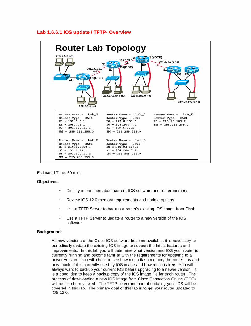
Lab 1.6.6.1 IOS update / TFTP- Overview
E1E0
S1
E0
S1
E0
S1
E0 E0
S0(DCE)
S0(DCE)
192.5.5.0 net
219.17.100.0 net 223.8.151.0 net
210.93.105.0 net
204.204.7.0 net199.6.13.0 net
201.100.11.0 net
205.7.5.0 net
S0(DCE)Lab_A
Lab_B
Lab_C
Lab_D Lab_E
Router Name - Lab_ARouter Type - 2514E0 = 192.5.5.1E1 = 205.7.5.1S0 = 201.100.11.1SM = 255.255.255.0
Router Name - Lab_BRouter Type - 2501E0 = 219.17.100.1S0 = 199.6.13.1S1 = 201.100.11.2SM = 255.255.255.0
Router Name - Lab_CRouter Type - 2501E0 = 223.8.151.1S0 = 204.204.7.1S1 = 199.6.13.2SM = 255.255.255.0
Router Name - Lab_DRouter Type - 2501E0 = 210.93.105.1S1 = 204.204.7.2SM = 255.255.255.0
Router Name - Lab_ERouter Type - 2501E0 = 210.93.105.2SM = 255.255.255.0
Router Lab Topology
Estimated Time: 30 min.
Objectives:
• Display information about current IOS software and router memory.
• Review IOS 12.0 memory requirements and update options
• Use a TFTP Server to backup a router's existing IOS image from Flash
• Use a TFTP Server to update a router to a new version of the IOSsoftware
Background:
As new versions of the Cisco IOS software become available, it is necessary toperiodically update the existing IOS image to support the latest features andimprovements. In this lab you will determine what version and IOS your router iscurrently running and become familiar with the requirements for updating to anewer version. You will check to see how much flash memory the router has andhow much of it is currently used by IOS image and how much is free. You willalways want to backup your current IOS before upgrading to a newer version. Itis a good idea to keep a backup copy of the IOS image file for each router. Theprocess of downloading a new IOS image from Cisco Connection Online (CCO)will be also be reviewed. The TFTP server method of updating your IOS will becovered in this lab. The primary goal of this lab is to get your router updated toIOS 12.0.

Tools / Preparation:
Prior to starting the lab you will need to connect a PC workstation withHyperTerminal to a router using the router’s console Interface with a roll-overcable. You will also need an Ethernet connection to the router. The instructor orlab assistant should have a Windows 9x PC with a TFTP server installed andhave the latest downloaded IOS 12.0 image on the PC hard drive. Verify that theTFTP server is accessible by the router. The Cisco TFTP server and latest IOSupdates can be downloaded from the web sites listed below. Although theinstructions in this lab for downloading the IOS image software can only be doneby someone with a CCO account, you should read through them to becomefamiliar with the process.
You should review Chapter 16 in the Cisco Networking Academy First-YearCompanion Guide and review semester 3 online curriculum lesson 1 prior tostarting this lab. Work individually or in teams.
Resources Required:
• PC with Monitor, keyboard, mouse, and power cords etc.
• Windows operating system (Win 95, 98, NT or 2000) installed on PC
• HyperTerminal program configured for router console connection
• PC connected to the Router console port with a roll-over cable.
• PC connected to a hub that the router is connected to or a crossovercable directly to the router
• PC on a network, running a TFTP daemon (server), that the router cansend and receive.
Web Site Resources:
Routing basicsGeneral information on routers 2500 series routers 1600 series routersTerms and acronymsIP routing protocol IOS command summaryCisco ConfigMaker information and download Cisco TFTP Server (Win 9x version) TFTP Command SyntaxCisco IOS images
Notes:

Step 1 - Login to the router.
Connect to the router with the console connection and log in. Enter the passwordcisco if prompted. Enter privileged mode with the enable command. Use thepassword of class
Step 2 - Check the current IOS version.
Use the show version command to check the IOS version
1. What version of the IOS is the router currently running?
Step 3 - Check the IOS image file and flash memory..
Use the show flash command to obtain information about Flash memory andthe IOS image.
2. Document the following information from the show flash command. a. How much flash memory is used and available?
b. What is the file that is stored in flash memory?
c. What is the size in bytes of the flash memory?

Step 4 - Review IOS image memory requirements.
Your options for updating the router IOS will vary depending on the router modelnumber, the version of IOS you are currently running, the amount of Flashmemory and the amount of DRAM memory the router has. The following tableshows various IOS images updates available and their memory requirements.(Note: All images shown here run from Flash memory)
CiscoRouterSeries
IOS Version /Feature Set
*ImageName Image Size
Reqd.FlashMemory
Reqd. DRAMmemory
1600 11.2(21) -**IP/IPX
C1600-ny-l.112-21.P.bin 3,729KB 4MB 2MB
1600 12.0(10) –**IP/IPX
C1600-ny-l.120-10.bin 5,031KB 6MB 4MB
250011.2(21) -**IP/IPX/AT/DEC
C2500-d-l.112-21.bin 5,292KB 8MB 4MB
250012.0(10)**IP/IPX/AT/DEC
C2500-d-l.120-10.bin 6,730KB 8MB 6MB
Notes: * The last character of the feature portion of the IOS image name(e.g. C1600-ny-l) is a lower case letter L not a number 1. ** Feature sets: IP= TCP/IP protocol, IPX = Novell IPX protocol, AT = AppleTalk protocol, DEC= DecNet protocol.
All images shown above run from Flash memory
Step 5 - Review options for obtaining the IOS image file.
You may obtain an IOS image by purchasing an IOS Software Feature Pack(SFP) or by downloading the IOS from the Cisco web site. You may also be ableto use a backup image from another router if it has a newer version. All optionsmust be in accordance with the IOS software licensing agreement.
A. Software Feature Pack (SFP)The SFP typically comes in a package for a specific router series such as a 2500and includes instructions, release notes and a CD with several IOS versions, theCisco TFTP server for Win 9x and the Router Software Loader (RSL). RSL is aWindows 9x software application utility that helps with loading new IOS imagesand it will be covered later in this lab. SFPs can be obtained from Cisco or anauthorized reseller. If you do not have an SFP with RSL you will need todownload the IOS image from the Cisco web site and use the TFTP method. TheRSL method of router IOS update will be covered in the next lab using theSoftware Feature Pack
B. Cisco web siteThe latest IOS versions can be downloaded from the Cisco web site(www.cisco.com) and you can choose from several different feature sets fordifferent router series (1600, 2500 etc.). There is also an abundance ofinformation on IOS versions, feature sets, capabilities and requirements. Onceyou download the image you can use it to update the router using TFTP. TheTFTP procedure will be covered in this lab. You will need a Cisco SmartNetService agreement and a Cisco Connection Online (CCO) login account in orderto download IOS files.
C. IOS Backup from another routerIf you have a router of the same series and model number with a newer IOS youcan sometimes copy the existing IOS from flash memory of that router to a TFTPserver. You can then load this image into the new router from the TFTP server.The TFTP procedure will be covered in this lab.
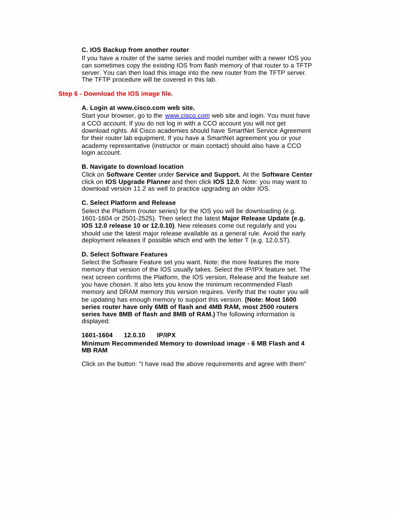
Step 6 - Download the IOS image file.
A. Login at www.cisco.com web site.Start your browser, go to the www.cisco.com web site and login. You must havea CCO account. If you do not log in with a CCO account you will not getdownload rights. All Cisco academies should have SmartNet Service Agreementfor their router lab equipment. If you have a SmartNet agreement you or youracademy representative (instructor or main contact) should also have a CCOlogin account.
B. Navigate to download locationClick on Software Center under Service and Support. At the Software Centerclick on IOS Upgrade Planner and then click IOS 12.0. Note: you may want todownload version 11.2 as well to practice upgrading an older IOS.
C. Select Platform and ReleaseSelect the Platform (router series) for the IOS you will be downloading (e.g.1601-1604 or 2501-2525). Then select the latest Major Release Update (e.g.IOS 12.0 release 10 or 12.0.10). New releases come out regularly and youshould use the latest major release available as a general rule. Avoid the earlydeployment releases if possible which end with the letter T (e.g. 12.0.5T).
D. Select Software FeaturesSelect the Software Feature set you want. Note: the more features the morememory that version of the IOS usually takes. Select the IP/IPX feature set. Thenext screen confirms the Platform, the IOS version, Release and the feature setyou have chosen. It also lets you know the minimum recommended Flashmemory and DRAM memory this version requires. Verify that the router you willbe updating has enough memory to support this version. (Note: Most 1600series router have only 6MB of flash and 4MB RAM, most 2500 routersseries have 8MB of flash and 8MB of RAM.) The following information isdisplayed:
1601-1604 12.0.10 IP/IPXMinimum Recommended Memory to download image - 6 MB Flash and 4MB RAM
Click on the button: "I have read the above requirements and agree with them"

E. Start IOS image download Confirm the IOS image information displayed (seebelow) and click on the File Name to start the download. Read the SoftwareLicense Agreement and then click YES that you agree. Select the HTTP (or FTP)download site. Click the "Save to Disk" button and then select the local directorywhere you want the IOS image file to be downloaded.
SoftwareDownloadFile name Description Size 'Bytes' Date Published More Infoc1600-ny-l.120-10.bin
IP/IPX 5151224 03/27/200005:46:22
?
Once the download is complete you can load the IOS image into the router usingTFTP.
Step 7 – Verify connection between router and TFTP server.
From the router you are going to update, enter ping xxx.xxx.xxx.xxx (theIP address of the workstation running the TFTP server.
3. What was the result of the ping command?
Step 8 – Verify TFTP server file location.
Check the TFTP server root directory location since this is where the backupcopy of the existing IOS and the new IOS image file should be stored. Be sureto copy the new downloaded IOS image to this directory on the PC beforestarting the IOS update. Click View/Options and note the location or browseand change the location to another directory.
4. What is the default location for the TFTP server root directory?
Step 9 – Backup the existing IOS software image.
Enter copy flash tftp at the router promptThe router will ask for the IP address or hostname of the tftp host. Enter the IPaddress of the tftp server.
5. What was the IP address of the TFTP server?
6. What was the file that was written to the TFTP server?

7. How did the router respond when copying the file?
Step 10 – Verify the backup IOS file copied to the TFTP server.
Check the TFTP server using Windows Explorer, the DIR command or ls UNIXcommand for the file you just wrote.
8. What is the size of the file that was written in bytes?
Step 11 - Load the new downloaded IOS image from the TFTP server..
Enter copy tftp flash at the router prompt. The router will ask for the IP addressor hostname of the tftp host. Enter the IP address of the tftp server. Enter thename of the new IOS image that was previously downloaded when prompted.You will also be prompted to erase flash before starting. This process will copythe new IOS software from a tftp host to router flash.
9. Write down some of the prompts and responses you saw on the router screen.Note: You can use HyperTerminal or Windows copy / paste to capture thecopy process as it progresses.
Step 12 - Check the IOS version after update.
Use the show version command to check the IOS version
10. What version of the IOS is the router now running after the update?
Step 13 - Check the IOS image file and flash memory after the update.
Use the show flash command to obtain information about Flash memory andthe IOS image.
11. Document the following information from the show flash command afterthe IOS update.a. How much flash memory is used and available?
b. What is the file that is stored in flash memory?
c. What is the size in bytes of the flash memory?

Lab 1.6.6.2 Router memory upgrade – Overview
E1E0
S1
E0
S1
E0
S1
E0 E0
S0(DCE)
S0(DCE)
192.5.5.0 net
219.17.100.0 net 223.8.151.0 net
210.93.105.0 net
204.204.7.0 net199.6.13.0 net
201.100.11.0 net
205.7.5.0 net
S0(DCE)Lab_A
Lab_B
Lab_C
Lab_D Lab_E
Router Name - Lab_ARouter Type - 2514E0 = 192.5.5.1E1 = 205.7.5.1S0 = 201.100.11.1SM = 255.255.255.0
Router Name - Lab_BRouter Type - 2501E0 = 219.17.100.1S0 = 199.6.13.1S1 = 201.100.11.2SM = 255.255.255.0
Router Name - Lab_CRouter Type - 2501E0 = 223.8.151.1S0 = 204.204.7.1S1 = 199.6.13.2SM = 255.255.255.0
Router Name - Lab_DRouter Type - 2501E0 = 210.93.105.1S1 = 204.204.7.2SM = 255.255.255.0
Router Name - Lab_ERouter Type - 2501E0 = 210.93.105.2SM = 255.255.255.0
Router Lab Topology
Estimated Time: 30 min.
Objectives:
• Display information about current IOS software and router memory • Review the steps for upgrading router DRAM memory • Review the steps for upgrading router Flash memory
Background:
In this lab you will determine what version and IOS your router is currently running and become familiar with the requirements for updating to a newer version. You will check to see how much flash memory the router has and how much of it is currently used by the IOS image (system code) and how much is free. You will also check the amount of DRAM (Dynamic Random Access Memory).
With Cisco 1600 and 2500 routers and most IOS images, the IOS usually runs from flash memory. If you determine that you do not have enough flash memory to update to a newer larger IOS image, you will need to perform a flash memory

upgrade. You also might need to upgrade the DRAM SIMM if you upgrade the Cisco IOS feature set or release or if your router maintains large routing tables or other memory-intensive features, such as spoofing or protocol translations. If a 2500 series router does NOT have 8MB Flash AND 4MB RAM, you will need to obtain and install additional memory modules. The procedure for upgrading the DRAM and flash SIMMs (Simple In-line Memory Modules) for a Cisco 2500 is outlined in this lab.
Tools / Preparation:
Prior to starting the lab you will need to connect a PC workstation with HyperTerminal to a router using the router's console Interface with a roll-over cable. You will also need an Ethernet connection to the router. A TFTP server should also be available to back up the IOS prior to replacing the flash SIMMs. Although the instructions in this lab for upgrading router flash memory may not be required for your lab setup, you should read through them to become familiar with the process.
You should review Chapter 16 in the Cisco Networking Academy First-Year Companion Guide and review semester 3 online curriculum lesson 1 prior to starting this lab. Work in teams. Note that detailed instructions can be found at the web site listed below. A PDF file can be downloaded.
Resources Required:
• PC with Monitor, keyboard, mouse, and power cords etc. • Windows operating system (Win 95, 98, NT or 2000) installed on PC • HyperTerminal program configured for router console connection • PC connected to the Router console port with a roll-over cable. • PC connected to a hub that the router is connected to or a crossover cable directly to the
router • PC on a network that the router can send and receive to running a TFTP daemon
(server). • Medium-size flat-blade screwdriver (1/4 inch [0.625 cm]) • ESD-preventive wrist strap • The DRAM SIMM required for your planned upgrade • System-code SIMM(s)
Web Site Resources:
Routing basics General information on routers 2500 series routers 1600 series routers Terms and acronyms IP routing protocol IOS command summary Cisco TFTP Server (Win 9x version) TFTP Command Syntax Maintaining and upgrading the 2500 router
Notes:
Step 1 - Login to the router.
Connect to the router with the console connection and log in. Enter the password cisco if prompted. Enter privileged mode with the enable command. Use the password of class
Step 2 - Check the current IOS version and amount of DRAM.
Use the show version command to check the IOS version and amount of DRAM
1. What version of the IOS is the router currently running?
2. How much DRAM is installed?
Step 3 - Check the IOS image file and flash memory.
Use the show flash command to obtain information about Flash memory and the IOS image.
3. Document the following information from the show flash command.
a) How much flash memory is used and available?

b) What is the file that is stored in flash memory?
c) What is the size in bytes of the flash memory?
Step 4 - Review IOS image memory requirements.
Your options for updating the router IOS will vary depending on the router model number, the version of IOS you are currently running, the amount of Flash memory and the amount of DRAM memory the router has. The following table shows various IOS images updates available and their memory requirements:
Cisco Router Series
IOS Version / Feature Set
*Image Name Image Size
Reqd. Flash Memory
Reqd. DRAM memory
1600
1.2(21) - **IP/IPX
C1600-ny-l.112-21.P.bin
3,729KB 4MB 2MB
1600
12.0(10) – **IP/IPX
C1600-ny-l.120-10.bin 5,031KB
6MB
4MB
2500 11.2(21) - **IP/IPX/AT/DEC
C2500-d-l.112-21.bin 5,292KB 8MB 4MB
2500
12.0(10) **IP/IPX/AT/DEC
C2500-d-l.120-10.bin 6,730KB 8MB 6MB
Notes: * The last character of the feature portion of the IOS image name (e.g. C1600-ny-l) is a lower case letter L not a number 1. ** Feature sets: IP = TCP/IP protocol, IPX = Novell IPX protocol, AT = AppleTalk protocol, DEC = DecNet protocol. All images shown above run from Flash memory

Section 2 - Cisco 2500 Series Router System Card Layouts
Cisco Model 2501, 2501, 2502, 2503, and 2504 System Board (SIMMs in place)
System Code SIMMS(Flash 0r PROMS)
Primary Memory(DRAM SIMM) Shared Memory
(DRAM)
Ethernet Serial 0 Serial 1 BAI Console Aux
Boo1 ROMs
Flash Memory Card Socket
Polarization Notch
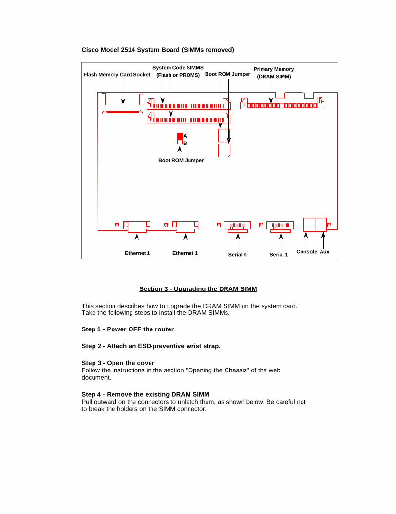
Cisco Model 2514 System Board (SIMMs removed)
System Code SIMMS(Flash or PROMS)
Primary Memory(DRAM SIMM)
Serial 0 Serial 1 Console Aux
Flash Memory Card Socket
Boot ROM Jumper
Boot ROM Jumper
AB
Ethernet 1 Ethernet 1
Section 3 - Upgrading the DRAM SIMM
This section describes how to upgrade the DRAM SIMM on the system card. Take the following steps to install the DRAM SIMMs.
Step 1 - Power OFF the router.
Step 2 - Attach an ESD-preventive wrist strap.
Step 3 - Open the cover Follow the instructions in the section "Opening the Chassis" of the web document.
Step 4 - Remove the existing DRAM SIMM Pull outward on the connectors to unlatch them, as shown below. Be careful not to break the holders on the SIMM connector.
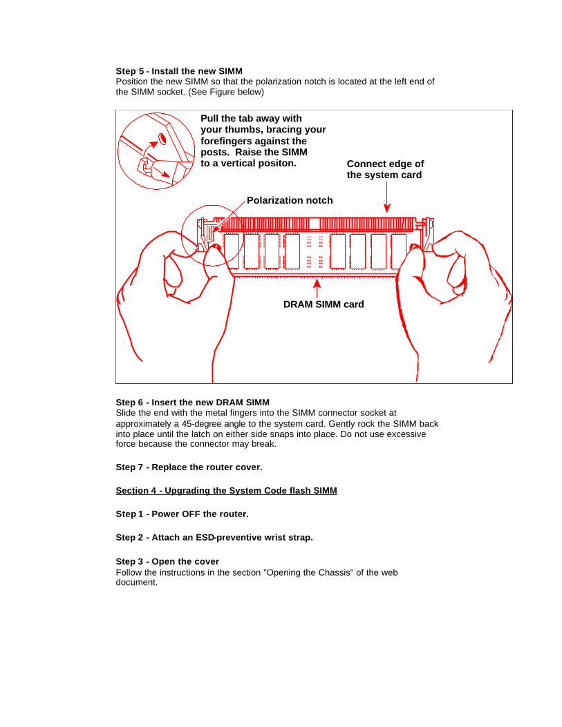
Step 5 - Install the new SIMM Position the new SIMM so that the polarization notch is located at the left end of the SIMM socket. (See Figure below)
Pull the tab away withyour thumbs, bracing yourforefingers against theposts. Raise the SIMMto a vertical positon. Connect edge of
the system card
DRAM SIMM card
Polarization notch
Step 6 - Insert the new DRAM SIMM Slide the end with the metal fingers into the SIMM connector socket at approximately a 45-degree angle to the system card. Gently rock the SIMM back into place until the latch on either side snaps into place. Do not use excessive force because the connector may break.
Step 7 - Replace the router cover.
Section 4 - Upgrading the System Code flash SIMM
Step 1 - Power OFF the router.
Step 2 - Attach an ESD-preventive wrist strap.
Step 3 - Open the cover Follow the instructions in the section "Opening the Chassis" of the web document.

Step 5 - Preparing to Install the System-Code SIMM There are two system-code (Flash memory) SIMM sockets on the system board. If you want to install system-code SIMMs in both sockets, the SIMMs must be the same size. For example, if a 4-MB system-code SIMM is already installed in your router, the new SIMM must also be 4 MB. This upgrade would give you a total of 8 MB.
Caution: The system code is stored on the Flash memory SIMMs, but new system-code SIMMs are shipped without preinstalled software. Before proceeding with this procedure, use the copy flash tftp command to back up the system code to a TFTP server. The TFTP server backup / restore process is described in a prior lab.
Step 6 - Replace Flash SIMM(s). If you are replacing a 4MB SIMM with an 8MB SIMM, that 8MB SIMM must be placed in SIMM socket 0. If you are adding SIMMs and they are to be placed side-by-side on the system card, the SIMMs must be of equal size e.g. two 4MB SIMMs, NOT one 4MB and one 8MB together.
Locate the SIMM sockets, labeled CODE 0 and CODE 1, on the system card. If necessary, remove the existing system-code SIMM by pulling outward on the connector holders to unlatch them. If you are installing system-code SIMMs in both sockets (CODE0 and CODE1), both SIMMs must be the same size. Populate the SIMM socket labeled CODE0 first; then populate CODE1
Step 7- Reconfigure flash partition (if necessary). After adding the Flash SIMM, if the router show flash command indicates that Flash memory has two partitions, you will need to reconfigure that partition from the router. The repartition process involves erasing Flash memory, so you will first have to reboot the router to run in ROM mode.
A. Reconfigure the router to boot to ROM. Change the config-register to 0x2101 and reload, using the following commands:
Router#configure terminal Enter configuration commands, one per line. End with CNTL/Z. Router(config)#config-register 0x2101 Router(config)#exit Router#reload
Note: This will bring the router up in boot mode and Flash will be idle. You can not change the partition when the router is running under a full IOS from Flash. You will see a different router prompt, but enable passwords and most commands will remain the same.
Router(boot)>enable Password: Router(boot)#

B. Erase Flash, including both partitions. Caution: You will need to have a backup IOS image already stored on our tftp server as this will erase all Flash files - and Flash is where a 2500 stores IOS by default!
Router(boot)#erase flash
The router will prompt you through erasing both partitions (you will need to confirm overwrite and erasure of flash).
C. Repartition Flash Now you must repartition the flash into one partition with a size of 8MB (if you have installed two 4MB SIMMs).
Router(boot)#configure t Router(boot)(config)#partition flash 1 8
D. Copy the stored IOS image back into flash Use the command copy tftp flash to retrieve the backed up IOS image back into flash memory. The TFTP server backup / restore procedure is described in a prior lab.
E. Change the config-register to boot from Flash Change the config register to cause the router to examine NVRAM for boot system commands ("config-register 0x2102") which will load the IOS image from flash. Exit and reload; the router should now read "8192k bytes of processor board System flash
Router(boot)(config)#config-register 0x2102 Router(boot)(config)#exit Router(boot)#reload

Lab 2.3.7 Switch characteristics – Overview
E1E0
S1
E0
S1
E0
S1
E0 E0
S0(DCE)
S0(DCE)
192.5.5.0 net
219.17.100.0 net 223.8.151.0 net
210.93.105.0 net
204.204.7.0 net199.6.13.0
net
201.100.11.0 net
205.7.5.0 net
S0(DCE)Lab_A
Lab_B
Lab_C
Lab_D Lab_E
Router Name - Lab_ARouter Type - 2514E0 = 192.5.5.1E1 = 205.7.5.1S0 = 201.100.11.1SM = 255.255.255.0
Router Name - Lab_BRouter Type - 2501E0 = 219.17.100.1S0 = 199.6.13.1S1 = 201.100.11.2SM = 255.255.255.0
Router Name - Lab_CRouter Type - 2501E0 = 223.8.151.1S0 = 204.204.7.1S1 = 199.6.13.2SM = 255.255.255.0
Router Name - Lab_DRouter Type - 2501E0 = 210.93.105.1S1 = 204.204.7.2SM = 255.255.255.0
Router Name - Lab_ERouter Type - 2501E0 = 210.93.105.2SM = 255.255.255.0
Router Lab Topology
Estimated time: 30 min.
Objectives:
• Determine the model number of an Ethernet switch and what physical interfaces (ports) it has
• Identify the cables, connections and devices that can attach to a switch • Check and/or modify HyperTerminal configuration parameters • Connect to the switch through its console using the PC and HyperTerminal
Background:
In this lab you will examine an Ethernet Switch to gather information about its physical characteristics and begin to appreciate the function of switches in a network. You will determine the model number and features of a specific switch including which interfaces are present and to which cabling and devices they are connected.
A switch is a Layer 2 (data link) network device that acts as the concentration point for the attachment of workstations, servers, routers, hubs and other switches. A "hub" is an earlier type of concentration device that provides multiple

ports similar to a switch except that with a hub all workstations share the bandwidth (10Mbps with Standard Ethernet) and collisions will occur. Hubs operate at half-duplex (can only send or receive) since they must be able to detect the collisions. A switch provides a dedicated point-to-point connection (virtual circuit) between two networking devices (such as workstations, servers and routers) so there are no collisions. Since they do not have to detect collisions, they can operate in full-duplex mode (simultaneous send and receive) which effectively doubles throughput. Ethernet switches are available in several speeds including 10Mbps (standard Ethernet), 100Mbps (Fast Ethernet) and 1000Mbps (Gigabit Ethernet). Switches are sometimes referred to as multi-port bridges and are the newest technology for today's Ethernet star-wired Local Area Networks (LANs). Like routers, switches are dedicated PCs which contain a CPU, RAM and an operating system (IOS). As with a router, a switch can be managed by connecting to the console port to allow you to view and make changes to the configuration. Many of the newer switches have a web (HTTP) server built in and can also be managed via their IP address using a PC and a browser interface such as Netscape or Internet Explorer. The ability to understand and configure switches is essential for network support.
Tools / Preparation:
A switch should be available with a PC workstation, connected as a console, with HyperTerminal installed and properly configured to access the switch. The switch should be exposed with all sides clearly vi sible so that all physical connections and cables can be inspected. Since there may be only one switch available, the instructor should demonstrate this lab at a minimum and students should work in larger teams to get hands on. While one team is doing switch labs the others could be doing web-based research on switches at the Cisco web site URLs listed below. Before beginning this lab you should read the Networking Academy Second Year Companion Guide, Chapter 2 on LAN Switching. You should also review semester 3 On-line Lesson 2. The following is a list of equipment required.
• Windows PC w/ HyperTerminal installed • Cisco Switch (19xx or 28xx model) with manuals • Console Cable (Roll-Over) • CAT5 Cable from the workstation to the switch
Web Site Resources:
• LAN Switching basics • General information on all Cisco products - (Scroll down to chapter 15 - Switches) • 1900 / 2820 series Ethernet switches • 2900 series Fast Ethernet switches • 3500 series Gigabit Ethernet switches • Cisco switch clustering technology

Notes:
Step 1 - Examine the LAN switch both front and back.
Answer the following questions. (Note: Answers will vary depending on the switch model). You may want to refer to the Installation and Configuration Guide for the switch you are working with.
1. What is the model number of the switch?
2. What is the system serial number of the switch?
3. Do you see a console port? (Y/N)
What port is it connected to on the Console terminal (PC workstation)?
4. What type of cable is the console cable (roll-over, cross-connect or straight-through cable)?
5. Do you see an AUI port? (Y/N)
What does AUI mean and what could this port be used for?

6. What type of cable or adapter could be used with the AUI port?
7. Is there a power ON/OFF switch? (Y/N)
How do you turn the switch on?
8. What is the total number of ports on the front of the switch for connection of workstations, servers, routers, hubs or other switches?
9. How many ports are 10Mbps Ethernet?
10. Are these crossover ports?
How can you tell?
11. What kind of connector(s) are used?
12. How many ports are 100Mbps Fast Ethernet?
13. Are these crossover ports?
How can you tell?
14. What kind of connector(s) are used?

15. What indicator lights (LEDs) are on the front of the switch?
16. What button is on the front of the switch?
What is it used for?
Step 2 - Review your answers to Step 1 and record interface information.
Use the following table to list and summarize the characteristics of all interfaces (or port connectors) on the switch. If there is no cable attached to a port, identify the cable type / connector that would normally be used.
Switch Interface / Port Identifier Cable type / Connector Device and port to which
cable is connected
Step 3 - Review the workstation's HyperTerminal configuration.
1. Click on Start/Programs/Accessories/Communications and then HyperTerminal. Right Click on the icon that is defined for console access to the switch and then click Properties. The icon may be named cisco.ht or something similar. If one does not exist you can create it using the settings shown in the answers to the worksheet. On the Properties screen, click the Phone Number Tab and then click on the Configure button. Fill in the following table with the information indicated.
Configuration Option Current Setting(s) COM Port Bits per second Data Bits Parity Stop Bits Flow control

Lab 2.3.10.1: Switch management console - Overview
E1E0
S1
E0
S1
E0
S1
E0 E0
S0(DCE)
S0(DCE)
192.5.5.0 net
219.17.100.0 net 223.8.151.0 net
210.93.105.0 net
204.204.7.0 net199.6.13.0 net
201.100.11.0 net
205.7.5.0 net
S0(DCE)Lab_A
Lab_B
Lab_C
Lab_D Lab_E
Router Name - Lab_ARouter Type - 2514E0 = 192.5.5.1E1 = 205.7.5.1S0 = 201.100.11.1SM = 255.255.255.0
Router Name - Lab_BRouter Type - 2501E0 = 219.17.100.1S0 = 199.6.13.1S1 = 201.100.11.2SM = 255.255.255.0
Router Name - Lab_CRouter Type - 2501E0 = 223.8.151.1S0 = 204.204.7.1S1 = 199.6.13.2SM = 255.255.255.0
Router Name - Lab_DRouter Type - 2501E0 = 210.93.105.1S1 = 204.204.7.2SM = 255.255.255.0
Router Name - Lab_ERouter Type - 2501E0 = 210.93.105.2SM = 255.255.255.0
Router Lab Topology
Estimated time: 60 min.
Objectives:
• Explore the switch Management Console User Interface Menus • Determine the switch model number and MAC address • Document the primary User Interface menu options • Use the Management Console menus to view / configure basic IP
address settings • Document the IP address configuration menu options • Check workstation network settings to verify compatibility with switch and
router settings
Background:
This lab will help develop a basic understanding of Ethernet switch management and will help prepare for more advanced switching lessons such as VLANs. You will work with the Switch Management Console User Interface Menus to configure some basic switch options. Switch management can be done through a menu-driven interface such as the Management Console or through a command line interface (CLI) as with most routers.

In this lab, you will console into the switch and view the menu options available with the User Interface Menu to become familiar with the types of settings and actions that can be performed when configuring a switch. You will also set the IP address of the switch using the Management Console and will use Control Panel / Networks utility on the workstation to verify that its IP address settings are compatible with the switch IP address. Familiarity with switches and their management is critical to the successful support of today's Ethernet networks.
Tools / Preparation:
Prior to starting the lab, the teacher or lab assistant should have a switch available with the default VLAN settings. A workstation with HyperTerminal should be available to console into the switch and an Ethernet connection should be available to Telnet into the switch. Since there may be only one switch available, the instructor should demonstrate this lab at a minimum and students should work in larger teams to get hands on. While one team is doing switch labs the others could be doing web-based research on switches at the Cisco web site URLs listed below. Before beginning this lab you may want to read the Networking Academy Second Year Companion Guide, Chapter 2 on LAN Switching. You should also review semester 3 On-line Lesson 2. The following is a list of equipment required.
• Windows PC w/ HyperTerminal installed (configured for console connection to switch)
• Cisco Switch (19xx, 28xx or 29xx model) • Console Cable (roll-over) • CAT 5 Ethernet Cable from the workstation to a switch Ethernet port
Web Site Resources: • LAN Switching basics • General information on all Cisco products - (Scroll down to chapter 15 - Switches) • 1900 / 2820 series Ethernet switches • 2900 series Fast Ethernet switches • 3500 series Gigabit Ethernet switches • Cisco switch clustering technology
Notes:
Step 1 - Connect the workstation to the switch console port and turn the switch on.
Wait a few minutes for the switch to "boot up" and it will display a menu of options known as the "Management Console" (1900 version). This exercise will help you become familiar with the various menu options available.

1. What is the model number for the switch?
2. What is the Ethernet Address (Layer 2 MAC address) of the switch?
3. Fill in the following table with the Main Menu options available. (Answers will vary depending on the switch model and firmware) Menu Options from a Cisco Catalyst 1924 (10 Mbps) Ethernet Switch
Menu Opt. Menu Option Description Sub-menu options (list two or more)
Step 2 - Use the Management Console menu options to configure IP access.
The IP address of the switch can be used to Ping or Telnet to the switch. It is not required to assign an IP address to a switch but it can be useful for remote switch management. On some newer switches the IP address can be used to access the switch using a web-based browser management interface. When managing a switch, the "Management domain" is always VLAN 1. All ports are assigned to VLAN 1 by default.
4. Select IP Configuration from the menus. Using the table below, list the first 5 "Settings" on the IP configuration menu and their values? What is the first "Action" available?

Menu Options from a Cisco Catalyst 1912 (10 Mbps) Ethernet Switch
Setting Setting / Action Description Setting Value I IP Address S Subnet mask D Default Gateway V Management VLAN M IP Address of DNS server 1 P Ping
5. Assign an IP address and subnet mask to the switch. Be sure to use an IP address and subnet mask that are compatible with the network or subnet the switch is currently on. If the switch is connected to Router Lab-A, Interface E1 (205.7.5.1) as shown in the standard lab setup diagram, then assign a compatible IP address and subnet mask to the switch.
IP Address:
Subnet Mask:
6. Verify that all ports are assigned to VLAN 1. List the ports that are currently assigned to default VLAN 1:
7. Configure a workstation with TCP/IP network settings to be compatible with the switch IP address and the router interface (E1) address. Be sure to set the workstation IP address, the subnet mask and the default gateway (nearside router interface).
IP Address:
Subnet Mask:
Default Gateway:

Lab 2.3.10.2: Switch port options – Overview
E1E0
S1
E0
S1
E0
S1
E0 E0
S0(DCE)
S0(DCE)
192.5.5.0 net
219.17.100.0 net 223.8.151.0 net
210.93.105.0 net
204.204.7.0 net199.6.13.0 net
201.100.11.0 net
205.7.5.0 net
S0(DCE)Lab_A
Lab_B
Lab_C
Lab_D Lab_E
Router Name - Lab_ARouter Type - 2514E0 = 192.5.5.1E1 = 205.7.5.1S0 = 201.100.11.1SM = 255.255.255.0
Router Name - Lab_BRouter Type - 2501E0 = 219.17.100.1S0 = 199.6.13.1S1 = 201.100.11.2SM = 255.255.255.0
Router Name - Lab_CRouter Type - 2501E0 = 223.8.151.1S0 = 204.204.7.1S1 = 199.6.13.2SM = 255.255.255.0
Router Name - Lab_DRouter Type - 2501E0 = 210.93.105.1S1 = 204.204.7.2SM = 255.255.255.0
Router Name - Lab_ERouter Type - 2501E0 = 210.93.105.2SM = 255.255.255.0
Router Lab Topology
Estimated time: 20 min.
Objectives:
• Work with the Management Console User Interface Menus to determine the switch modelnumber, MAC address and firmware revision
• Use the System configuration menu to configure Fragment Free operation
• Use the Port configuration menu to enable Full-Duplex operation
• Use the Port configuration menu to enable Port Fast operation
Background:
In this lab you will work with the Management Console interface menus toconfigure a switch to operate in Fragment-Free switching mode. You will alsoconfigure a port to enable FULL DUPLEX and Port Fast operation. Most switchescan be configured with these options.
Fragment-Free OperationThere are 3 modes switches can operate in; 1) Cut-through or Fast-Forward, 2)Store-and-Forward and 3) Fragment-Free. In Fast-Forward mode, the switch onlyreads the destination MAC address of the Frame header and then immediatelyforwards the frame. This mode is the fastest but can also forward collisionfragments of less than 64 bytes (a runt). Store-and forward waits for the entireframe to be received (up to 1,518 bytes) before forwarding the frame. It is the

slowest switching mode but results in the fewest errors. Fragment-free modereduces delay by making the forwarding decision after the first 64 bytes havebeen received. This means that no runts will be forwarded which is the mostcommon type of bad Ethernet frame. Fragment-free is the best compromisebetween speed and errors. Cisco switches can be set to operate in Store-andforward, Fragment-free or Fast Forward modes depending on the model.
Full Duplex OperationWhen Full Duplex is enabled on a port it can double the bandwidth by allowing itto simultaneously transmit and receive. This means that a 10Mbps Ethernet portcan operate at 20Mbps as long as the network interface of the attached device(NIC or router interface) can also support Full Duplex operation. Since a switchprovides virtual circuit to the device with no collisions, this is dedicated bandwidthto the device. A 100Mbps Fast Ethernet port can operate at 200Mbps dedicatedbandwidth. Full Duplex operation must be set for each port.
Port Fast OperationWhen a switch port comes up it normally goes thru the normal 802.1d SpanningTree states of Blocking, Listening, Learning, and then Forwarding. This processcan take from up to 45 seconds to occur. When Port fast mode (spanning tree) isenabled, the Spanning Tree Protocol (STP) can transition the port's state fromBlocking to Forwarding without going through the intermediate states of Listeningand Learning. This can be beneficial especially in Novell Network IPXenvironments where the client request can sometimes timeout due to the time ittakes for a switch port to respond.
Tools / Preparation:
Prior to starting the lab, the teacher or lab assistant should have a switchavailable with the default VLAN settings. A workstation with HyperTerminalshould be available to console into the switch and an Ethernet connection shouldbe available to Telnet into the switch. Since there may be only one switchavailable, the instructor should demonstrate this lab at a minimum and studentsshould work in larger teams to get hands on. While one team is doing switch labsthe others could be doing web-based research on switches at the Cisco web siteURLs listed below. Before beginning this lab you should read the NetworkingAcademy Second Year Companion Guide, Chapter 2 -LAN Switching. Youshould also review semester 3 On-line Lesson 2. The following is a list ofequipment required.
• Windows PC w/ HyperTerminal installed (configured for consoleconnection to switch)
• Cisco Switch (19xx or 28xx model)
• Console Cable (roll-over)
• Straight-through CAT 5 Ethernet Cable from the workstation to a switchEthernet port
Web Site Resources:• LAN Switching basics • General information on all Cisco products - (Scroll down to chapter 15 - Switches) • 1900 / 2820 series Ethernet switches • 2900 series Fast Ethernet switches• 3500 series Gigabit Ethernet switches• Cisco switch clustering technology

Notes:
Step 1 - Connect the workstation to the switch console port and turn the switch on.
Wait a few minutes for the switch to "boot up" and it will display a menu ofoptions known as the "Management Console" (1900 version).
1. What is the model number for the switch?
2. What is the Ethernet Address (Layer 2 MAC address) of the switch?
3. What is the switch firmware revision and type?
Step 2 - Configure the switch for fragment-free operation.
Select the [S] System option from the main menu and review the menu optionsunder Settings
4. What is the current switch mode set to?
5. What menu option will allow you to change the mode?
6. What options are available?

Step 3 - Configure a port for full duplex.
7. List the ports that are available to select from: Identify Port:
8. Is full duplex enabled? What option is used to enable it?
Step 4 - Configure a Port for Port Fast mode.
From the port configuration menu, Select the Port Fast configuration option fromthe menu.
9. What option selects Port fast?
Step 5 – Check switch IP configuration.
From the [N] Network Management option on the main menu, select [I] for IPconfiguration.
10. Does the switch have an IP address? If so, what is it?
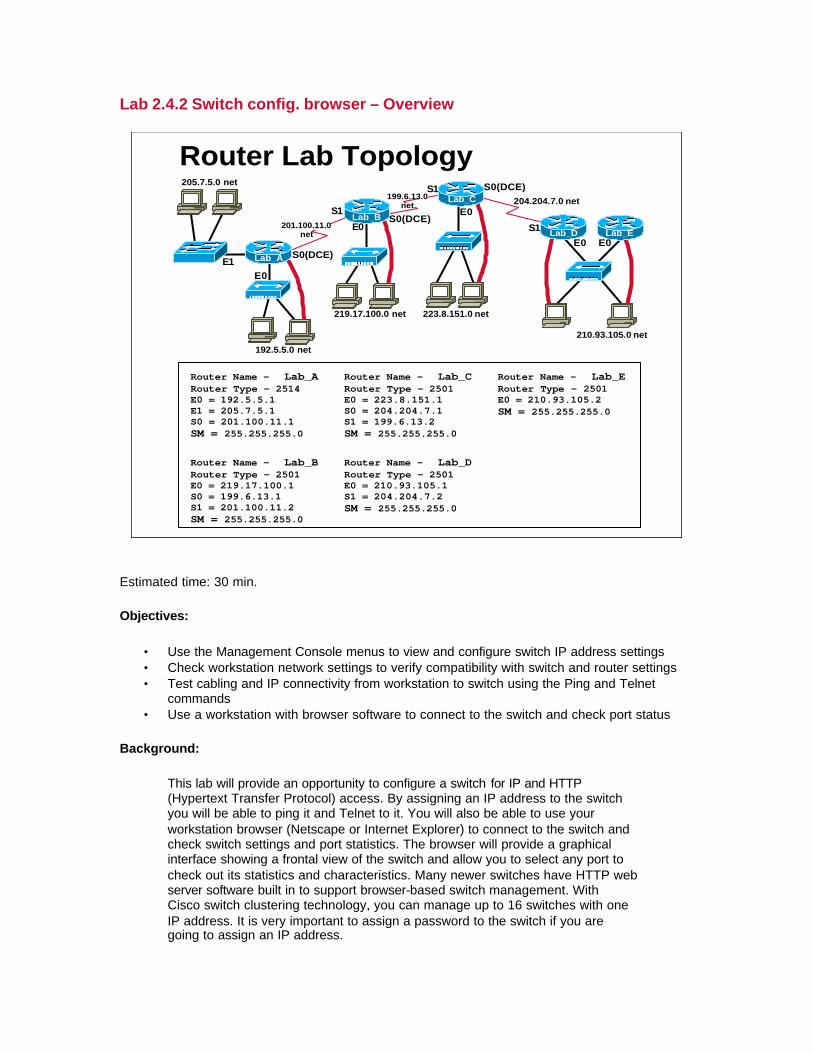
Lab 2.4.2 Switch config. browser – Overview
E1E0
S1
E0
S1
E0
S1
E0 E0
S0(DCE)
S0(DCE)
192.5.5.0 net
219.17.100.0 net 223.8.151.0 net
210.93.105.0 net
204.204.7.0 net199.6.13.0 net
201.100.11.0 net
205.7.5.0 net
S0(DCE)Lab_A
Lab_B
Lab_C
Lab_D Lab_E
Router Name - Lab_ARouter Type - 2514E0 = 192.5.5.1E1 = 205.7.5.1S0 = 201.100.11.1SM = 255.255.255.0
Router Name - Lab_BRouter Type - 2501E0 = 219.17.100.1S0 = 199.6.13.1S1 = 201.100.11.2SM = 255.255.255.0
Router Name - Lab_CRouter Type - 2501E0 = 223.8.151.1S0 = 204.204.7.1S1 = 199.6.13.2SM = 255.255.255.0
Router Name - Lab_DRouter Type - 2501E0 = 210.93.105.1S1 = 204.204.7.2SM = 255.255.255.0
Router Name - Lab_ERouter Type - 2501E0 = 210.93.105.2SM = 255.255.255.0
Router Lab Topology
Estimated time: 30 min.
Objectives:
• Use the Management Console menus to view and configure switch IP address settings • Check workstation network settings to verify compatibility with switch and router settings • Test cabling and IP connectivity from workstation to switch using the Ping and Telnet
commands • Use a workstation with browser software to connect to the switch and check port status
Background:
This lab will provide an opportunity to configure a switch for IP and HTTP (Hypertext Transfer Protocol) access. By assigning an IP address to the switch you will be able to ping it and Telnet to it. You will also be able to use your workstation browser (Netscape or Internet Explorer) to connect to the switch and check switch settings and port statistics. The browser will provide a graphical interface showing a frontal view of the switch and allow you to select any port to check out its statistics and characteristics. Many newer switches have HTTP web server software built in to support browser-based switch management. With Cisco switch clustering technology, you can manage up to 16 switches with one IP address. It is very important to assign a password to the switch if you are going to assign an IP address.

Tools / Preparation:
Prior to starting the lab, the teacher or lab assistant should have a switch available with the default VLAN settings. A workstation with HyperTerminal should be available to console into the switch and an Ethernet connection to Telnet and browser into the switch. Since there may be only one switch available, the instructor should demonstrate this lab at a minimum and students should work in larger teams to get hands on. While one team is doing switch labs the others could be doing web-based research on switches at the Cisco web site URLs listed below. Before beginning this lab you may want to read the Networking Academy Second Year Companion Guide, Chapter 2 –LAN Switching. You should also review semester 3 On-line Lesson 2. The following is a list of equipment required.
• Windows PC w/ HyperTerminal installed (configured for console connection to switch)
• Cisco Switch (19xx or 28xx model) • Console Cable (roll-over) • CAT 5 Ethernet Cable from the workstation to a switch Ethernet port
Web Site Resources:
• LAN Switching basics • General information on all Cisco products - (Scroll down to chapter 15 - Switches) • 1900 / 2820 series Ethernet switches • 2900 series Fast Ethernet switches • 3500 series Gigabit Ethernet switches • Cisco switch clustering technology
Notes:
Step 1- Connect the workstation to the switch console port and turn the switch on.
Depending on the switch you will need either a rollover RJ45 cable with a DB9 adapter (on the PC end) or a DB9 to DB9 null modem (modem eliminator) cable. Wait a few minutes for the switch to boot up and it will display a menu of options known as the “Management Console”.

1. What is the model number for the switch?
2. What is the Ethernet Address (Layer 2 MAC address) of the switch?
Step 2- Use the Management Console to configure IP access to the switch.
The IP address of the switch can be used to Ping or Telnet to the switch and browse into it. It is not required to assign an IP address to a switch but it is recommended for switch management. When managing a switch, the “Management domain” is always VLAN 1. All ports are assigned to VLAN 1 by default.
3. Select [N] Network Management and then [I] IP Configuration from the menus. Assign an IP address and subnet mask to the switch. Be sure to use an IP address and subnet mask that are compatible with the network or subnet the switch is currently on. If the switch is connected to Router Lab-A, Interface E1 (205.7.5.1) as shown in the standard lab setup diagram, then assign a compatible IP address and subnet mask to the switch.
IP Address:
Subnet Mask:
4. Select [V] Virtual LAN from the menu and verify that all ports are assigned to VLAN 1. List the ports that are currently assigned to default VLAN 1:
Step 3- Use the Management Console to configure HTTP access.
5. Select the [N] Network Management menu and verify that the switch will accept HTTP requests. What option is used to configure the switch to be an HTTP server?
(Note: This option may not be available on all switches)
Step 4 - Configure the workstation for Ethernet access to the switch.
Configure the workstation with TCP/IP network settings to be compatible with the switch IP address and the router interface (E1) address. Be sure to set the workstation IP address, subnet mask and default gateway (nearside router interface).
6. Write down the workstation IP address information here:
IP Address:
Subnet Mask:
Default Gateway:
Step 5 – Ping the IP address of the switch.
Connect the workstation Ethernet cable (straight-through) to port 1 on the switch and use the ping command from the workstation DOS prompt to test connectivity and IP configuration between the workstation and switch.
C:\WINDOWS> ping 205.7.5.4
7. Was the ping command successful?
Step 6 – Telnet to the switch IP address.
Telnet to the switch from the workstation DOS prompt to test upper layer connectivity and IP configuration between the workstation and switch. You should see the same menu as when you are connected via the console.
C:\WINDOWS> telnet 205.7.5.4
8. Was the telnet successful?
Step 7 – Use your browser to access the switch.
Start your browser software (Netscape or Internet Explorer). Type in the IP address you just assigned to the switch in the browser address area where you would normally type in the URL of a web site. The Switch Management Graphical User Interface (GUI) should be displayed by the HTTP server in the switch. Remember you can always use the forward and back buttons with the browser. The browser GUI is somewhat limited in what you can configure.
9. Did the Switch Manager browser interface come up?

Step 8 – Make some configuration changes to the switch using the browser interface.
10.Enter a name for the switch:
11. Enter a password for the switch and confirm it.
12. What color will the port be if the link is faulty or the port is disabled?
13. Select the port where your workstation is connected (port 1) and click on it with the mouse. Scroll down the port table until you get to port 0/1. What is the current actual duplex mode?
Change the mode from Half Duplex to Full Duplex. (The NIC in your workstation may not support full duplex operation).
14. Check the port statistics for frames received and transmitted by clicking on the “Stats” button. Enter the number of packets below:
Good Frames Received:
Packets Transmitted:

Lab 3.3.4.1 Creating VLANs – Overview
E1E0
S1
E0
S1
E0
S1
E0 E0
S0(DCE)
S0(DCE)
192.5.5.0 net
219.17.100.0 net 223.8.151.0 net
210.93.105.0 net
204.204.7.0 net199.6.13.0
net
201.100.11.0 net
205.7.5.0 net
S0(DCE)Lab_A
Lab_B
Lab_C
Lab_D Lab_E
Router Name - Lab_ARouter Type - 2514E0 = 192.5.5.1E1 = 205.7.5.1S0 = 201.100.11.1SM = 255.255.255.0
Router Name - Lab_BRouter Type - 2501E0 = 219.17.100.1S0 = 199.6.13.1S1 = 201.100.11.2SM = 255.255.255.0
Router Name - Lab_CRouter Type - 2501E0 = 223.8.151.1S0 = 204.204.7.1S1 = 199.6.13.2SM = 255.255.255.0
Router Name - Lab_DRouter Type - 2501E0 = 210.93.105.1S1 = 204.204.7.2SM = 255.255.255.0
Router Name - Lab_ERouter Type - 2501E0 = 210.93.105.2SM = 255.255.255.0
Router Lab Topology
Estimated time: 45 min.
Objectives:
This Lab will focus on your ability to accomplish the following tasks:
• Console into the switch to determine the firmware version • Check the IP address and subnet mask for the switch • Use the Management console to check VLAN related menu options • Check workstation network settings to verify compatibility with switch and
router settings • Create a new VLAN, name it and move member ports to it. • Test VLANs functionality by moving a workstation from one VLAN to
another
Background:
In this lab you will work with Ethernet Virtual Local Area Networks or VLANs. VLANs can be used to separate groups of users based on function rather than physical location. Normally all of the ports on a switch are in the same default VLAN 1. A Network Administrator can create additional VLANs and move some

ports into those VLANs to create isolated groups of users regardless of where they are physically located. This creates smaller broadcast domains which helps to reduce and localize network traffic. If a switch with 24 ports is divided into 2 VLANs of 12 ports each, the users on one VLAN will not be able to access resources (such as servers or printers) on the other VLAN. VLANs can also be created using ports from multiple switches that are “trunked” together on a backbone. In order for two VLANs to communicate they must be connected by a router. Security can be controlled using router Access Control Lists (ACLs) which will be covered in a future lab.
You will console into the switch and use the Management Console User Interface menus to view the options available to manage VLANs and will check the current VLAN configuration. You will also use Telnet to access the switch and check some settings as well as move your connection from one VLAN to another to determine the affects of the "Management Domain". When managing a switch, the Management Domain is always VLAN 1. The Network Administrator's workstation must have access to a port in the VLAN 1 Management Domain. All ports are assigned to VLAN 1 by default. This lab will also help demonstrate how VLANs can be used to separate traffic and reduce broadcast domains.
Tools / Preparation:
Prior to starting the lab, the teacher or lab assistant should have a switch available with the default VLAN settings. A workstation with HyperTerminal should be available to console into the switch and an Ethernet connection should be available to Telnet into the switch. Since there may be only one switch available, the instructor should demonstrate this lab at a minimum and students should work in larger teams to get hands on. While one team is doing switch labs the others could be doing web-based research on switches at the Cisco web site URLs listed below. Before beginning this lab you should read the Networking Academy Second Year Companion Guide, Chapter 3 - VLANs. You should also review Semester 3 On-line Lesson 3. Following is a list of equipment required.
• Two Windows PC workstations w/ HyperTerminal installed (configured for console connection to switch and compatible IP addresses)
• Cisco Switch (19xx or 28xx model) • Console Cable (roll-over) and DB-9/RJ45 adapter or DB-9 null modem
cable. • CAT 5 Ethernet Cable from each workstation to a switch Ethernet port
Web Site Resources:
LAN Switching basics General information on all Cisco products - (Scroll down to chapter 16 - Switches) 1900 / 2820 series Ethernet switches 2900 series Fast Ethernet switches 3500 series Gigabit Ethernet switches Virtual LANs for 1900/2820 Switches

Notes:
Step 1 - Console into the LAN switch.
Console into the switch by attaching the workstation serial port to the switch console port with the rollover cable and answer the following questions. Use the switch attached to Router Lab-A or other another one (Note: Answers will vary depending on switch model number)
1. What is the model number of the switch?
2. Does this switch have standard edition or Enterprise edition software?
3. What is the Firmware version of the switch?
4. What option on the switch menu is used to create or modify VLANS?
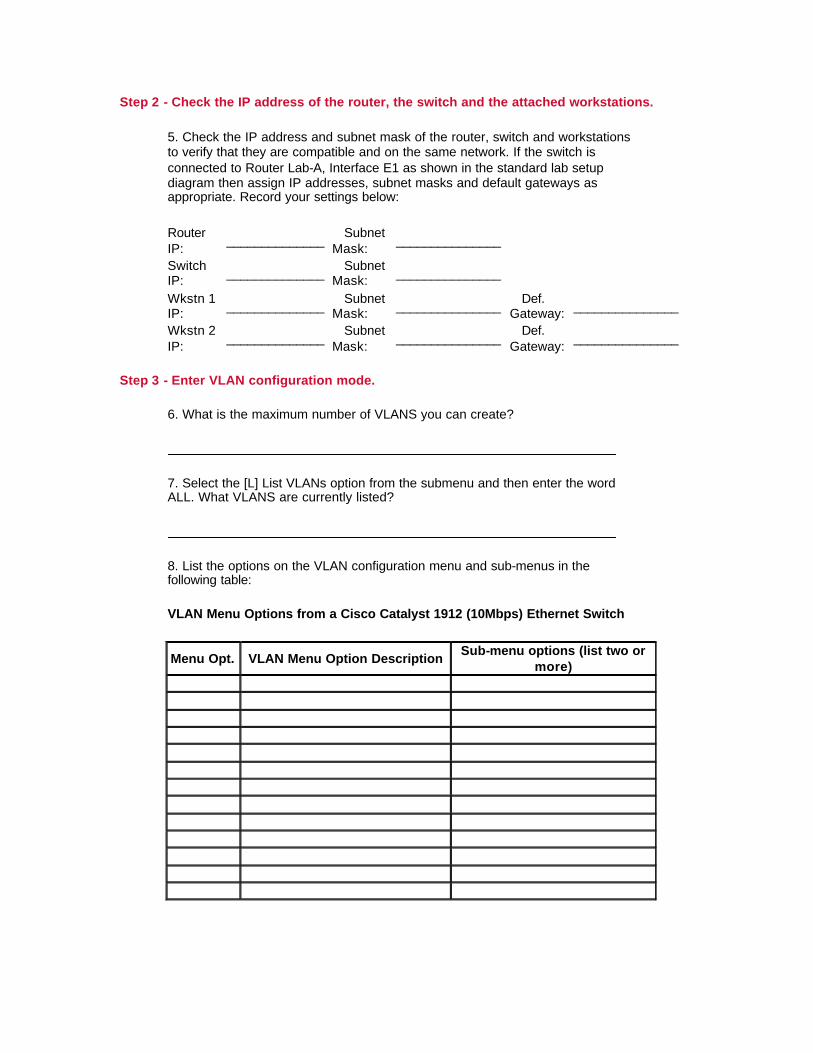
Step 2 - Check the IP address of the router, the switch and the attached workstations.
5. Check the IP address and subnet mask of the router, switch and workstations to verify that they are compatible and on the same network. If the switch is connected to Router Lab-A, Interface E1 as shown in the standard lab setup diagram then assign IP addresses, subnet masks and default gateways as appropriate. Record your settings below:
Router IP: ______________ Subnet
Mask: _______________
Switch IP: ______________ Subnet
Mask: _______________
Wkstn 1 IP: ______________ Subnet
Mask: _______________ Def. Gateway: _______________
Wkstn 2 IP: ______________ Subnet
Mask: _______________ Def. Gateway: _______________
Step 3 - Enter VLAN configuration mode.
6. What is the maximum number of VLANS you can create?
7. Select the [L] List VLANs option from the submenu and then enter the word ALL. What VLANS are currently listed?
8. List the options on the VLAN configuration menu and sub-menus in the following table:
VLAN Menu Options from a Cisco Catalyst 1912 (10Mbps) Ethernet Switch
Menu Opt. VLAN Menu Option Description Sub-menu options (list two or more)

Step 4 - Using the VLAN menu options, configure the VLANs.
NOTE: The following steps were performed on a Catalyst 1912 WS-C1912C-EN (12-port) switch with Enterprise Edition firmware version V8.01.02. Your answers may vary.
9. Check the configuration of the default VLAN by selecting [M] Modify VLANs option and then select VLAN 1. What are the current member ports in VLAN 1?
10. Create a new Ethernet VLAN and name it. Give it a name (eg: your last name plus an number: smith1). What name did you give it?
11. What is the VLAN number for your new VLAN?
12. List the steps required to create and name the new VLAN:
13. Assign ports 7 thru 12 and port B to the your new VLAN: List the steps required to do this:
14. Check VLAN 1 again. What changes do you see?
Exit out to the main menu, then to the Management Console.
Step 5 - Test the functionality of the 2 VLANs.
To see your VLAN in action, set up two workstations and verify that the IP addresses are on the same subnetwork (See Step 2). Restart computers as needed.
From Workstation 1, plug the Ethernet cable from the NIC card into a port from 1-6 on the switch. From Workstation 2, plug the Ethernet cable from the NIC card into a port from 1-6 on the switch.
15. Issue a ping to each workstation. Was the ping successful?

16. Now take Workstation 2's Ethernet port from the switch and plug it into one of the ports on VLAN 2 (ports 7-12). Ping each workstation again. Was the ping successful?

Lab 3.3.4.2 Switch management VLANs – Overview
E1E0
S1
E0
S1
E0
S1
E0 E0
S0(DCE)
S0(DCE)
192.5.5.0 net
219.17.100.0 net 223.8.151.0 net
210.93.105.0 net
204.204.7.0 net199.6.13.0 net
201.100.11.0 net
205.7.5.0 net
S0(DCE)Lab_A
Lab_B
Lab_C
Lab_D Lab_E
Router Name - Lab_ARouter Type - 2514E0 = 192.5.5.1E1 = 205.7.5.1S0 = 201.100.11.1SM = 255.255.255.0
Router Name - Lab_BRouter Type - 2501E0 = 219.17.100.1S0 = 199.6.13.1S1 = 201.100.11.2SM = 255.255.255.0
Router Name - Lab_CRouter Type - 2501E0 = 223.8.151.1S0 = 204.204.7.1S1 = 199.6.13.2SM = 255.255.255.0
Router Name - Lab_DRouter Type - 2501E0 = 210.93.105.1S1 = 204.204.7.2SM = 255.255.255.0
Router Name - Lab_ERouter Type - 2501E0 = 210.93.105.2SM = 255.255.255.0
Router Lab Topology
Estimated time: 45 min.
Objectives:
This Lab will focus on your ability to accomplish the following tasks:
• Console into the switch and check switch characteristics and configuration parameters.
• View / Configure the IP address and subnet mask for the switch • Check workstation network settings to verify compatibility with switch and
router settings • Use the Management console to check and change VLAN configuration
for the switch • Telnet to the switch based on VLAN and port location • Work with the switch Management Domain
Background:
In this lab you will work with Virtual Local Area Networks (VLANs). You will console into the switch and view the menu options available to manage VLANs and will check the current VLAN configuration. You will also use Telnet to access the switch and check some settings as well as move your connection from one VLAN to another to determine the affects of the "Management Domain". When

managing a switch, the Management Domain is always VLAN 1. The network administrator's workstation must have access to a port in the VLAN 1 Management Domain. All ports are assigned to VLAN 1 by default.
Tools / Preparation:
Prior to starting the lab, the teacher or lab assistant should have a switch available with the default VLAN settings. A workstation with HyperTerminal should be available to console into the switch and an Ethernet connection should be available to Telnet into the switch. Since there may be only one switch available, the instructor should demonstrate this lab at a minimum and students should work in larger teams to get hands on. While one team is doing switch labs the others could be doing web-based research on switches at the Cisco web site URLs listed below. Before beginning this lab you should read the Networking Academy Second Year Companion Guide, Chapter 3 - VLANs. You should also review Semester 3 On-line Lesson 3. Following is a list of equipment required:
• Two Windows PC workstations w/ HyperTerminal installed (configured for console connection to switch)
• Cisco Switch (19xx or 28xx model) • Console Cable (roll-over) and DB-9/RJ45 adapter or DB-9 null modem
cable. • CAT 5 Ethernet Cable from the workstation to a switch Ethernet port
Web Site Resources:
LAN Switching basics General information on all Cisco products - (Scroll down to chapter 16 - Switches) 1900 / 2820 series Ethernet switches 2900 series Fast Ethernet switches 3500 series Gigabit Ethernet switches Cisco switch clustering technology Virtual LANs for 1900/2820 Switches
Notes:
Step 1. Console into the LAN switch.
Console into the switch by attaching the workstation serial port to the switch console port with a rollover cable and answer the following questions. Use the switch attached to Router Lab-A or other another one (Note: Answers will vary depending on switch model number)

1. What is the model number of the switch?
2. Does this switch have Standard Edition or Enterprise Edition software?
3. What is the Firmware version of the switch?
4. What option on the menu is used to set IP address of the switch?
5. What option on the switch menu is used to create or modify VLANS?
Step 2. Assign an IP address to the switch.
6. Assign an IP address and subnet mask to the switch. Be sure to use an IP address and subnet mask that are compatible with the network or subnet the switch is currently on. If the switch is connected to Router Lab-A, Interface E1 as shown in the standard lab setup diagram, then assign a compatible IP address and subnet mask to the switch.
IP Address: ____________________ Subnet Mask: _____________________
Step 3. Check VLAN configuration options.
7. Select VLAN option from the menu. How many VLANS can be configured with this switch?
8. Verify that all ports are assigned to VLAN 1. List the ports that are currently assigned to VLAN1.

9. List the first three "Actions" that are available on the VLAN submenu. Which menu option is used to move a port to a different VLAN?
Menu Opt. VLAN Menu Option Description Sub-menu options (list two or more)
Step 4. Attach a workstation and Telnet to the switch.
Connect the workstation to the switch with a straight-through CAT5 Ethernet cable using port 12 on the switch. Verify that the workstation has IP address, Subnet Mask and Default Gateway settings that are compatible with the switch and router. Telnet to the switch from the workstation DOS prompt.
10. What command did you use?
11. Were you able to Telnet to the switch?
12. Move port 12 to VLAN 2. What happened to the Telnet session?
12. With the workstation attached to port 12 on VLAN 2 can you still manage the switch?
14. Why or Why not?
15. Move your workstation connection to port 11 on the switch. Can you Telnet to the switch now?
16. Why or why not?

17. Explain why your Telnet session failed when you move your workstation from port 11 (VLAN 1) to port 12 (VLAN 2) on the switch.

Lab 3.4.4.1 Switch Firmware Update / TFTP – Overview
E1E0
S1
E0
S1
E0
S1
E0 E0
S0(DCE)
S0(DCE)
192.5.5.0 net
219.17.100.0 net 223.8.151.0 net
210.93.105.0 net
204.204.7.0 net199.6.13.0 net
201.100.11.0 net
205.7.5.0 net
S0(DCE)Lab_A
Lab_B
Lab_C
Lab_D Lab_E
Router Name - Lab_ARouter Type - 2514E0 = 192.5.5.1E1 = 205.7.5.1S0 = 201.100.11.1SM = 255.255.255.0
Router Name - Lab_BRouter Type - 2501E0 = 219.17.100.1S0 = 199.6.13.1S1 = 201.100.11.2SM = 255.255.255.0
Router Name - Lab_CRouter Type - 2501E0 = 223.8.151.1S0 = 204.204.7.1S1 = 199.6.13.2SM = 255.255.255.0
Router Name - Lab_DRouter Type - 2501E0 = 210.93.105.1S1 = 204.204.7.2SM = 255.255.255.0
Router Name - Lab_ERouter Type - 2501E0 = 210.93.105.2SM = 255.255.255.0
Router Lab Topology
Estimated time: 20 min.
Objectives:
• Display information about current Switch Firmware. • Review switch memory and update options • Use a TFTP Server to update a switch to a new version of the Firmware
software
Background:
As new versions of the Cisco switch Firmware software become available, it is necessary to periodically update the existing Firmware image to support the latest features and improvements. In this lab you will determine what version of Firmware your switch is currently running and become familiar with the requirements for updating to a newer version. The process of downloading a new switch firmware image from Cisco Connection Online (CCO) will be also be reviewed. The TFTP server method of updating your firmware will be covered in this lab. The primary goal of this lab is to get your switch updated to Enterprise Edition.
Note:
If your switch currently has an older version of the standard edition firmware, you must update to the newest version of the standard edition first and then you can update to the enterprise edition.
Tools / Preparation:
Prior to starting the lab you will need to connect a PC workstation with HyperTerminal to a Switch using the Switch's console Interface with a roll-over cable. You will also need an Ethernet connection to the Switch. The instructor or lab assistant should have a Windows 9x PC with a TFTP server installed and have the latest downloaded firmware image on the PC hard drive. Verify that the TFTP server is accessible by the Switch. The Cisco TFTP server and latest firmware updates can be downloaded from the web sites listed below. Since there may be only one switch available, the instructor should demonstrate this lab at a minimum and students should work in larger teams to get hands on. While one team is doing switch labs the others could be doing web-based research on switches at the Cisco web site URLs listed below.
You should review Chapters 2 and 3 in the Cisco Networking Academy Second-Year Companion Guide and review semester 3 online curriculum lesson 3 prior to starting this lab. Although the instructions in this lab for downloading the firmware image software can only be done by someone with a CCO account, you should read through them to become familiar with the process.
Resources Required:
• PC with Monitor, keyboard, mouse, and power cords etc. • Windows operating system (Win 95, 98, NT or 2000) installed on PC • HyperTerminal program configured for router console connection • PC connected to the Switch console port with a roll-over cable and DB-
9/RJ45 adapter or DB-9 null modem cable. • PC connected to a hub that the router is connected to or a crossover
cable directly to the router • PC on a network that the router can send and receive to running a TFTP
daemon (server
Web Site Resources:
LAN Switching basics General information on all Cisco products - (Scroll down to chapter 16 - Switches) 1900 / 2820 series Ethernet switches 2900 series Fast Ethernet switches 3500 series Gigabit Ethernet switches Virtual LANs for 1900/2820 Switches

Notes:
Step 1. Download new switch firmware version.
Go to www.cisco.com and login with your CCO account (your instructor or academy contact should be able to do this). Click on Software Center under Services and Support. Click on LAN Switching Software, then click on Catalyst 1900, then click on Download Cisco Catalyst 1900 Software Image.
NOTE: If you have Standard Edition firmware you must upgrade to newest version then upgrade to Enterprise Edition. Depending on the version of the switch firmware, you may not be able to upgrade to Enterprise Edition firmware.
Step 2. Login to the Switch.
Select option [M] for Menu then [F] for Firmware
Step 3. Check the current firmware version.
IF your switch does not have Enterprise Edition software you will need to upgrade to the Standard edition version of the current Firmware then you can upgrade to the same version of Enterprise Edition.
1. What version of firmware is the switch currently running?
Step 4. Set IP address of the switch.
Under main menu select [N] Network Management, then select [I] IP configuration, after that select [I] IP address and [S] for subnet mask. Make sure that the IP address and subnet mask are on the same network as the TFTP server.
Step 5. Prepare for firmware update.
a. Set the IP address of the TFTP server using option [S] TFTP server name or IP address.
b. Set the File name of the upgrade using [F] Filename for firmware upgrades

Step 6. Install firmware update.
In the firmware configuration select [T] for system TFTP upgrade. The Switch will ask you to confirm the upgrade. After you confirm that you want to proceed with firmware upgrade the Switch will become unresponsive for approximately 1 minuet or so. This is normal.
Step 7. Confirm Firmware upgrade.
From main menu select [M] for Menu then [F] for Firmware
2. What version of firmware is the switch running?

Lab 3.4.4.2 Multi-Switch VLANs – Overview
E1E0
S1
E0
S1
E0
S1
E0 E0
S0(DCE)
S0(DCE)
192.5.5.0 net
219.17.100.0 net 223.8.151.0 net
210.93.105.0 net
204.204.7.0 net199.6.13.0 net
201.100.11.0 net
205.7.5.0 net
S0(DCE)Lab_A
Lab_B
Lab_C
Lab_D Lab_E
Router Name - Lab_ARouter Type - 2514E0 = 192.5.5.1E1 = 205.7.5.1S0 = 201.100.11.1SM = 255.255.255.0
Router Name - Lab_BRouter Type - 2501E0 = 219.17.100.1S0 = 199.6.13.1S1 = 201.100.11.2SM = 255.255.255.0
Router Name - Lab_CRouter Type - 2501E0 = 223.8.151.1S0 = 204.204.7.1S1 = 199.6.13.2SM = 255.255.255.0
Router Name - Lab_DRouter Type - 2501E0 = 210.93.105.1S1 = 204.204.7.2SM = 255.255.255.0
Router Name - Lab_ERouter Type - 2501E0 = 210.93.105.2SM = 255.255.255.0
Router Lab Topology
Estimated time: 60 min.
Objectives:
This Lab will focus on your ability to accomplish the following tasks:
• Console into the switch to determine the firmware version • Check the IP address and subnet mask for the switch • Use the Management console to check VLAN related menu options • Check workstation network settings to verify compatibility with switch and
router settings • Create a new VLAN, name it and move member ports to it. • Test VLANs functionality by moving a workstation from one VLAN to
another • Enable ISL (Inter-Switch Link) trunking on trunk ports for the two
switches

Background:
In this lab you will work with Ethernet Virtual Local Area Networks or VLANs. VLANs can be used to separate groups of users based on function rather than physical location. Normally all of the ports on a switch are in the same default VLAN 1. A Network Administrator can create additional VLANs and move some ports into those VLANs to create isolated groups of users regardless of where they are physically located. This creates smaller broadcast domains which helps to reduce and localize network traffic. If a switch with 24 ports is divided into 2 VLANs of 12 ports each, the users on one VLAN will not be able to access resources (such as servers or printers) on the other VLAN. VLANs can also be created using ports from multiple switches that are "trunked" together on a backbone. In order for two VLANs to communicate they must be connected by a router. Security can be controlled with router Access Control Lists (ACLs) which will be covered in a future lab.
You will console into the switch and use the Management Console User Interface menus to view the options available to manage VLANs and will check the current VLAN configuration. You will also use Telnet to access the switch and check some settings as well as move your connection from one VLAN to another to determine the affects of the "Management Domain". When managing a switch, the Management Domain is always VLAN 1. The Network Administrator's workstation must have access to a port in the VLAN 1 Management Domain. All ports are assigned to VLAN 1 by default. This lab will also help demonstrate how VLANs can be used to separate traffic and reduce broadcast domains.
Tools / Preparation:
Prior to starting the lab, the teacher or lab assistant should have two switches available with the default VLAN settings and each switch must be running the Enterprise Edition firmware. If your switches are not, then the Enterprise Edition firmware must be downloaded from the Cisco web site by a person with a CCO login account (your academy contact or instructor). The procedure for upgrading switch firmware was covered in the prior lab (3.4.4 Lab 1). A workstation with HyperTerminal should be available as a console and for Telnetting into the switch. Since there may be only a couple of switches available, the instructor should demonstrate this lab at a minimum and students should work in larger teams to get hands on. While one team is doing switch labs the others could be doing web-based research on switches at the Cisco web site URLs listed below. Before beginning this lab you should read the Networking Academy Second Year Companion Guide, Chapter 3 - VLANs. You should also review semester 3 On-line Lesson 3. The following is a list of equipment required.
• Two Windows PC workstations w/ HyperTerminal installed (configured for console connection to switch and compatible IP addresses)
• Two Cisco Switches (19xx or 28xx model) with Enterprise Edition software with at least one 100Base-TX (CAT 5 copper) trunk port (A or B).
• Console Cable (roll-over or null cable) • CAT 5 Ethernet Cable from each workstation to a switch Ethernet port • CAT 5 cross-over cable to connect the switch trunk ports (100Base-TX)
Web Site Resources:
LAN Switching basics General information on all Cisco products - (Scroll down to chapter 16 - Switches) 1900 / 2820 series Ethernet switches 2900 series Fast Ethernet switches 3500 series Gigabit Ethernet switches Virtual LANs for 1900/2820 Switches
Notes:
Step 1. Console into the LAN switch.
Console into the switch by attaching the workstation serial port to the switch console port and answer the following questions. (Note: Answers will vary depending on switch model number). For this lab you have to have Enterprise Edition software to create VLANs that span multiple switches. If the switch needs to be upgraded to Enterprise edition software refer to the lab on Switch Firmware upgrade. You may need to use the [F] Firmware option from the switch main menu to determine the answers to the following.
1. What is the model number of the switch?
Switch-A:
Switch-B:
2. Does this switch have standard edition or Enterprise edition software?
Switch-A:
Switch-B:

3. What is the Firmware version of the switch?
Switch-A:
Switch-B:
4. What option on the switch menu is used to create or modify VLANS?
Switch-A:
Switch-B:
Step 2. Check the IP address of the switch and the attached workstations.
5. Check the IP address and subnet mask of the switch and workstations to verify that they are compatible and on the same network. Record your settings below:
Switch A IP: ________________ Subnet Mask: ________________
Switch B IP: ________________ Subnet Mask: ________________
Wkstn 1 IP ________________ Subnet Mask: ________________
Wkstn 2 IP: ________________ Subnet Mask: ________________
Step 3. Enter VLAN configuration mode.
6. What is the maximum number of VLANS that can be created?
7. Select the [L] List VLANs option from the submenu and then enter the word ALL. What VLANS are currently listed?

8. List the options on the VLAN configuration menu and sub-menus in the following table:
VLAN Menu Options from a Cisco Catalyst 1912 (10 Mbps) Ethernet Switch
Menu Opt. VLAN Menu Option Description Sub-menu options (list two or more)
Step 4. Using the VLAN menu options, configure the VLANs.
NOTE: The following steps were performed on a Catalyst 1912 WS-C1912C-EN (12-port) switch with Enterprise Edition firmware version V8.01.02 (Switch-A) and Catalyst 1924 WS-C1924C-EN (24-port) switch with Enterprise Edition firmware version V8.01.02 (Switch-B) Your answers may vary.
9. Check the configuration of the default VLAN by selecting [M] Modify VLANs option and then select VLAN 1. What are the current member ports in VLAN 1?
10. Create two new Ethernet VLANs and name them. Give each one a name (eg: your last name plus the number of the VLAN: smith10 or smith20). What names did you give them?
For the two VLANs you create use numbers 10 and 20. Assign a SAID to each VLAN using the [I] 802.10 SAID VLANs option. Use SAID 10 and 20 for VLAN 10 and 20. Assign the first half of the ports to VLAN 10 and the second half to VLAN 20. Repeat this on Switch-B using the same names, VLAN number and same SAID.
Step 5. Enable "Trunking" on port B of both Switch-A and Switch-B.
Under VLAN configuration select [T] Trunk Configuration and select port B. In the Trunk B Configuration Menu select [T] Trunking then select 1 to turn trunking on. Repeat for Switch-A and Switch-B. By default 1-1005 VLANs are allowed to use the trunk port.
NOTE: You need to use a CAT 5 crossover cable to connect Switch-A port B to Switch-B port B. This assumes that each of your switches has at least

one 100Base -TX (CAT 5 copper) trunk or backbone port (port A or B). Some switches have one 100Base -TX and one 100Base -FX (fiber) trunk port and some have two 100Base -FX ports depending on the model.
Lab 4.5.6: Switched LAN design – Overview
Estimated time: 60 min.
Objectives:
• Analyze requirements for a simple Local Area Network with Internet access. • Design a Layer 1 and 2 topology based on switched Ethernet and given requirements • Determine the type, number and location of Ethernet switches and cabling required
based on wiring closet locations for MDF and multiple IDFs based and a simple floor plan • Research the Cisco web site and those of Cisco vendors for models and costs
Background:
This lab will help prepare for the Case Study. In this lab you will be given some basic requirements for a small LAN that spans multiple buildings. Your focus is on the physical topology and Data link layer components. The goal is to replace an aging 10Base2 thinnet Ethernet network with current technology Ethernet switches and cabling based on structured cabling standards and the extended star topology. You will decide which type of Ethernet switches to use and where to place them. You will also determine which type of cabling to use based on the requirements given. Your users will need access to several servers and they will need to be placed in the most effective locations. You will use vendor catalogs and web based research to find out the model numbers and costs of various switched Ethernet solutions.
Tools / Preparation:
This is a research lab and will not require a physical lab setup. You will need access to data communications equipment catalogs and web access for research. Use the Cisco web site URLs listed below. Work in teams of 3 or more. Before beginning this lab you should read the Networking Academy Second Year Companion Guide, Chapter 4 – LAN Design. You should also review semester 3 On-line Lesson 4. The following is a list of equipment required.
• PC with Internet access for product research • Data communication vendors catalogs
Web Site Resources: • LAN Switching basics • General information on all Cisco products - (Scroll down to chapter 15 - Switches) • 1900 / 2820 series Ethernet switches • 2900 series Fast Ethernet switches • 3500 series Gigabit Ethernet switches • Cisco switch clustering technology
Notes:

Step 1. Review the requirements.
You are designing a LAN for a small company with one location and several buildings that need to be interconnected. Use the building diagram and requirements listed to decide what type of switches and cabling should be run where.
1. There are 3 buildings in a campus arrangement - Admin, Engineering and Manufacturing
2. Admin is Building A, Engineering is building B and Manufacturing is building C
3. The Admin building is between Engineering and Manufacturing 4. The distances between the buildings are shown in the diagram 5. There is a wiring closet in each of the buildings 6. The wiring closet for the POP is in the Admin building 7. There are 35 PCs and 5 printers that need network access in the Admin
building 8. There are 27 PCs and 3 printers that need network access in the
Engineering building 9. There are 18 PCs and 2 printers that need network access in the
Manufacturing building 10. The customer wants the fastest Ethernet switching technology available
for the backbone 11. The customer wants the keep cost down for the workstation connections 12. All users need access to the Internet and two centralized file and print
servers 13. Engineering users need local access to a high performance
departmental server
Engineering Bldg B(30 data drops rqd.)Eng. Server
Admin Bldg A(40 data drops rqd.)2 central Servers
Manufacturing Bldg C(20 data drops rqd.)
350 ft. 250 ft.

XYZ Company Data Network
Fill in the table and answer the following questions based on your knowledge of Ethernet switching equipment, routers and structured cabling standards.
1. Admin building A - MDF / POP Equipment (40 data)
Equip. Type Model No. Qty. No./Type
Ports Description/Function Cost
2. Engineering building B – IDF 1 Equipment (30 data)
Equip. Type Model No. Qty. No./Type
Ports Description/Function Cost
(1)
3. Manufacturing building C – IDF 2 Equipment (20 data)
Equip. Type Model No. Qty. No./Type
Ports Description/Function Cost
4. What type of cabling will you run from the switches in the wiring closets to the users desktop workstations and why?
5. What will be the speed of these links?
6. What are some terms related to this type of cabling?
7. What type of cabling will you run from the MDF/POP in building A to buildings B and C and why?

8. What will be the speed of these links?
9. What are some terms related to this type of cabling?
10. Why is the wiring closet in the Admin building the best place for the MDF?

Lab 5.2.2: Routed & routing protocols – Overview
E1E0
S1
E0
S1
E0
S1
E0 E0
S0(DCE)
S0(DCE)
192.5.5.0 net
219.17.100.0 net 223.8.151.0 net
210.93.105.0 net
204.204.7.0 net199.6.13.0 net
201.100.11.0 net
205.7.5.0 net
S0(DCE)Lab_A
Lab_B
Lab_C
Lab_D Lab_E
Router Name - Lab_ARouter Type - 2514E0 = 192.5.5.1E1 = 205.7.5.1S0 = 201.100.11.1SM = 255.255.255.0
Router Name - Lab_BRouter Type - 2501E0 = 219.17.100.1S0 = 199.6.13.1S1 = 201.100.11.2SM = 255.255.255.0
Router Name - Lab_CRouter Type - 2501E0 = 223.8.151.1S0 = 204.204.7.1S1 = 199.6.13.2SM = 255.255.255.0
Router Name - Lab_DRouter Type - 2501E0 = 210.93.105.1S1 = 204.204.7.2SM = 255.255.255.0
Router Name - Lab_ERouter Type - 2501E0 = 210.93.105.2SM = 255.255.255.0
Router Lab Topology
Estimated time: 30 min.
Objectives:
• Compare the characteristics of routed and routing protocols and cite examples of each
• Examine a router to determine which routed and routing protocols are active
• Practice commands to determine which routed and routing protocols are supported(show IP route, show protocols, show running config, router ?)
• Match terms for routed and routing protocols
• Diagram the relationship between: routed & routing protocols, dynamic & static protocols,interior vs exterior protocols, distance vector, link state & hybrid routing protocols
Background:
This lab will reinforce your knowledge and understanding of routed and routingprotocols, the primary protocols that enable a router to function. You will reviewexamples of each type of protocol and use various IOS commands at the routerto discover which routed and routing protocols are currently running or active onthe router. You will also use the help facility to explore what protocols the routercould support that may not be currently running. Understanding the distinction

between routed and routing protocols is critical to mastering the concepts ofinternetworking.
Routed protocolsProtocols are the language or rules of communication between devices on anetwork. Routed protocols are those protocols that can be routed. Layer 3(network) addressing information is put in the header of the data packet, whichenables the packet to get to it's destination across multiple networks. They arealso called routable protocols, meaning they are able to be routed. In order for aprotocol to be routable the addressing method must have at least two parts; anetwork number and a node number. It is the network portion of the address thatallows a packet to be routed from one network to another. All devices in anetwork normally run the same routed protocol, which is like a commonlanguage, in order to communicate. Most LAN protocols are routed protocols.
The most common routed protocol is the Internet Protocol or IP, which is aninternational standard. IP is sometimes referred to as TCP/IP, but TCP is actuallya transport (Layer 4) protocol and is not involved directly with the routable IPprotocol that works at Layer 3. In order for a device (workstation, server, routeretc.) to communicate on the Internet, it must be running IP. IP addresses are 32bits and have a network portion and a node portion that is typically assigned by anetwork administrator. Other routed LAN protocols are Novell's IPX, AppleTalkand Decnet.
Routing protocolsRouting protocols are used by routers to communicate between themselves inorder to dynamically exchange information about the networks they can reachand the desirability of the routes available. They are typically called dynamicrouting protocols and they facilitate the process of routing. They are not neededin a small network if only static routes are used. Routing protocol packets take upbandwidth and operate independently of the routed data packets that passthrough the network. There is no information in an IP packet that is related to therouting protocol being used. Routers periodically send information about routes(routing tables) to each other so that when they receive a routed protocol packet(such as IP) they know where to send it. If we think of the routed protocoladdress like an address on a letter, the routing protocol is like a messengerrunning between the routers to tell them which routes are open and which onesare the fastest. Routing protocols can be broadly categorized based on whetherthey are interior or exterior, and subdivided by type: distance vector or link state.
Interior Routing ProtocolsInterior routing protocols are used within a private network. As an example, acompany may have a number of LANs in different geographical locations that areconnected by routers and dedicated WAN links (such as T1 or Frame relay). If allof these routers are under a common administration or autonomous system (notconnected through the Internet), then they would use an interior routing protocol.Interior routing protocols can be subdivided by type: (1) Distance vector, (2) LinkState, and (3) Hybrid. The distinction is in the metrics they use to select routesand in how routing table updates are stored and exchanged.
Exterior routing protocolsExterior routing protocols are used to communicate between autonomoussystems and over the Internet. Examples of exterior protocols include BorderGateway Protocol (BGP) and Exterior Gateway protocol (EGP). BGP is the mostcommon exterior routing protocol and the latest version is BGP4.

Tools / Preparation:
Prior to starting the lab, the teacher or lab assistant should have the standardrouter lab with all 5 routers set up and have a routing protocol enabled (RIP orIGRP). Workstations with HyperTerminal should be available to console into therouters. Work individually or in teams. Before beginning this lab you may want toread the Networking Academy Second Year Companion Guide, Chapter 5 –Routing Protocols: IGRP. You should also review Semester 3 On-line Lesson 5.The following is a list of equipment required.
• Standard Cisco 5-router lab setup with hubs and switches
• Workstations to connect to the routers
• Console Cable (roll-over)
• CAT 5 Ethernet Cable from the workstation to the hub or switch
Web Site Resources:
• Routing basics • RIP routing protocol • IGRP routing protocol• EIGRP routing protocol• OSPF routing protocol • BGP routing protocol • EGP routing protocol• Tech tips for IGRP and EIGRP routing protocol• Configuring IP routing protocols• Basic IP addressing and Troubleshooting guide
Notes:
Step 1 - Review Interior Gateway routing protocols.
1. The following table lists some of the most common interior routingprotocols. Fill in the table with the information requested based on yourknowledge. You may look up answers in the text or online or use the website resources.

Interior Gateway Routing Protocols
Routing Protocol Protocol Type:(distance vector,link state, hybrid)
Developed by:(Vendor /Standards)
Characteristics/Notes
RIP (v1 and v2)(Routing informationprotocol)
IGRP (InteriorGateway RoutingProtocol)
OSPF (OpenShortest Path First)
EIGRP (EnhancedInterior GatewayRouting Protocol)
Step 2 - Check to see which ROUTING protocols the router can understand.
Routing protocols enable the router to learn about other routes. To see the list ofIP routing protocols supported and the networks and routes that have beenlearned, use the show IP route command from user mode.
Router> show IP route
2. What are some of the routing protocols supported?
You can also see the routing protocols supported in analphabetical list with definitions. Enter privileged mode, thenconfig mode and then use the help by typing router ?.
Router(config)# router ?
3. Are the routing protocols listed the same?

Step 3 - Determine which ROUTING protocols are in use.
You can see which interfaces and networks are defined for the routing protocolsin use. This means they will advertise and received routing updates on thoseinterfaces. Use the show run command to see which protocol is active and onwhich interfaces.
Router# show run
4. What routing protocol is being used and which networks will beadvertised?
Step 4 - Check to see which ROUTED protocols the router can understand.
Routed (or routable) protocols enable packets to move from one network toanother. To see the list of routed protocols supported, enter privileged mode,then config mode and use the help by typing ?. You will see many commands butyou should be able to pick out the routed protocols.
Router(config)# ?
5. Which routed protocols can you see in the list?
Step 5 - Determine which ROUTED protocols are in use.
Each router in our lab is directly connected to at least one network, and mostrouters are connected to 2 or more networks. To view which routed protocols arein use on your router enter the show protocols command at the user mode.
router> show protocols
6. Which routed protocols are in use? On which interface(s)?

Step 6 – Fill in the tree diagram of routed and routing protocols.
7. Fill in the boxes on the tree diagram showing the relationship andprotocol names for the more common routed and routing protocols. Thiswill help you visualize the tree when working with these protocols. Startat the top with routed and routing then branch off into interior, exterior,distance vector, link state, etc. Use the abbreviations and acronyms inthe legend at the bottom to fill in the boxes. You must use them all.
Routed and Routing Protocols
ROUTED ROUTING
Legend:IP = Internet Protocol, IPX = Internetwork Packet Exchange, A/T = AppleTalk, D.V.= Distance Vector, L.S. = Link State, HYB = Hybrid, BGP = Border GatewayProtocol, EGP = Exterior Gateway Protocol, RIP = Routing Information Protocol,IGRP = Interior Gateway Routing Protocol, OSPF = Open Shortest Path First,EIGRP = Enhanced Interior Gateway Routing Protocol, INTERIOR, EXTERIOR

Lab 5.4.3: Migrating RIP to IGRP - Overview
E1E0
S1
E0
S1
E0
S1
E0 E0
S0(DCE)
S0(DCE)
192.5.5.0 net
219.17.100.0 net 223.8.151.0 net
210.93.105.0 net
204.204.7.0 net199.6.13.0 net
201.100.11.0 net
205.7.5.0 net
S0(DCE)Lab_A
Lab_B
Lab_C
Lab_D Lab_E
Router Name - Lab_ARouter Type - 2514E0 = 192.5.5.1E1 = 205.7.5.1S0 = 201.100.11.1SM = 255.255.255.0
Router Name - Lab_BRouter Type - 2501E0 = 219.17.100.1S0 = 199.6.13.1S1 = 201.100.11.2SM = 255.255.255.0
Router Name - Lab_CRouter Type - 2501E0 = 223.8.151.1S0 = 204.204.7.1S1 = 199.6.13.2SM = 255.255.255.0
Router Name - Lab_DRouter Type - 2501E0 = 210.93.105.1S1 = 204.204.7.2SM = 255.255.255.0
Router Name - Lab_ERouter Type - 2501E0 = 210.93.105.2SM = 255.255.255.0
Router Lab Topology
Estimated time: 30 min.
Objectives:
• Verify the routing protocols are working properly • Check routing table and interpret network entries • Check for static routes and remove them if necessary • Compare RIP to IGRP based on administrative distance • Convert a RIP-based router network to IGRP
Background:
In this lab you will work with two dynamic interior routing protocols - Router Information Protocol (RIP) and Interior Gateway Routing Protocol (IGRP). Routing protocols are used by routers to communicate between themselves in order to dynamically exchange information about the networks they can reach and the desirability of the routes available. Routed protocols (such as IP and IPX) are those protocols that can be routed between networks to enable packets to get from one location to another. Routers can run multiple routing and routed protocols.

Both RIP and IGRP are distance-vector routing protocols. RIP is the oldest routing protocol and uses only hop count as a metric to determine the best path or route. IGRP is a Cisco proprietary protocol that uses metrics such as bandwidth and delay to determine the best path. It may be desirable for a router network using RIP to convert to IGRP because IGRP has a much higher hop count limitation and uses bandwidth as a metric, thus bringing about better routing decisions when working with an internetwork that has alternative paths.
You will console into the router and check the status of the IP routing table and verify the networks that are reachable by each router. You will add IGRP to a router that has only RIP on it and then remove RIP. The ability to apply and interpret routing protocols is essential to maintaining internetworks.
Tools / Preparation:
Prior to starting the lab, the teacher or lab assistant should have the standard router lab with all 5 routers set up with RIP enabled. Workstations with HyperTerminal should be available to console into the routers. Work individually or in teams. Before beginning this lab you may want to read the Networking Academy Second Year Companion Guide, Chapter 5 - Routing Protocols: IGRP. You should also review Semester 3 On-line Lesson 5. The following is a list of equipment required.
• Standard Cisco 5-router lab setup with hubs and switches • Workstations to connect to the routers • Console Cable (roll-over) • CAT 5 Ethernet Cable from the workstation to the hub or switch
Web Resources:
• Routing basics • General information on routers • 2500 series routers • 1600 series routers • Terms and acronyms • IP routing protocol IOS command summary
Notes:

Step 1. Verify the routers have learned about the other networks in the lab.
1. To display the routing table and see the routing updates that have occurred and the networks the router knows about, issue the following command:
router> show IP route
2. What letter appears in the first column of the routing table for any network/subnet directly connected to the router?
3. What letter(s) might appear in the first column of the routing table for any other networks NOT directly connected to the router? (refer to the legend at the top of the display from the show IP route command)
Step 2. Determine the directly connected networks.
Each router in our lab is directly connected to at least one network, and most routers are connected to 2 or more networks.
1. In the table below, list the networks (class A, B, or C - NOT subnets) to which each router is directly connected (you will be using this information when you enable IGRP).
2. What is the difference between a router's interface address and the attached network address?
Lab-A Lab-B Lab-C Lab-D Lab-E
Step 3. Determine if there are static routes and remove them.
1. What letter would appear in the first column of the routing table for any network/subnet for which there is a static route?

2. If there any static routes configured on the routers in this lab they need to be removed, since our goal here is for the routers to learn all routes via the IGRP routing protocol. To find the configuration statements for the static routes, issue the following command. Are there any static routes?
router#show running-config
(notice any command of the form "IP route …", they would be near the end of the output)
3. Enter config mode and remove any static routes with the command:
router#config term
4. Remove each of the static routes with a NO command of the form:
router(config)#no IP route …
(be sure to enter exactly what you found in the show running-config, but with a "no" in front.)
Step 4. Routes learned with RIP and IGRP.
1. What letter appears in the first column of the routing table for any network/subnet learned via RIP?
Once you have successfully and completely converted to IGRP, each of the entries learned via RIP should be replaced with a similar entry.
2. What will the letter in the first column be when the network/subnet is being learned via IGRP?
Step 5. Enable IGRP routing.
1. Issue the following commands:
router(config)#router igrp 100
router(config-router)#network a.b.c.d
(where a.b.c.d is the actual network address, for example 204.204.7.0)
(Add a network statement for each network directly connected to the router being configured; refer to the table you filled in above.)

Step 6. Verify that IGRP is now running and configured correctly.
1. Issue the command:
Router> show IP protocol
2. At this point, you are still running two routing protocols for IP; RIP and IGRP, and both should be listed. The output includes the administrative distance of the two routing protocols - fill in those values below.
RIP:
IGRP:
Administrative distance is used to choose the routing protocol to prefer when there is more than one in use, with the lowest value being preferred. Since IGRP has a lower administrative distance, it will be preferred. However, if some of the routers in our lab are not yet configured correctly for using IGRP, RIP information will still be learned and used! Continue to issue the command show IP route until there is no more RIP information in the table, and then turn off RIP.
Step 7. What is the command to turn off the RIP routing protocol?

Lab 5.4.6.1: Configuring IGRP - Overview
E1E0
S1
E0
S1
E0
S1
E0 E0
S0(DCE)
S0(DCE)
192.5.5.0 net
219.17.100.0 net 223.8.151.0 net
210.93.105.0 net
204.204.7.0 net199.6.13.0 net
201.100.11.0 net
205.7.5.0 net
S0(DCE)Lab_A
Lab_B
Lab_C
Lab_D Lab_E
Router Name - Lab_ARouter Type - 2514E0 = 192.5.5.1E1 = 205.7.5.1S0 = 201.100.11.1SM = 255.255.255.0
Router Name - Lab_BRouter Type - 2501E0 = 219.17.100.1S0 = 199.6.13.1S1 = 201.100.11.2SM = 255.255.255.0
Router Name - Lab_CRouter Type - 2501E0 = 223.8.151.1S0 = 204.204.7.1S1 = 199.6.13.2SM = 255.255.255.0
Router Name - Lab_DRouter Type - 2501E0 = 210.93.105.1S1 = 204.204.7.2SM = 255.255.255.0
Router Name - Lab_ERouter Type - 2501E0 = 210.93.105.2SM = 255.255.255.0
Router Lab Topology
Estimated time: 30 min.
Objectives:
• To learn how to configure IGRP as the network's routing protocol
• Adjust configurable IGRP metrics
Background:
In this lab you will work with Cisco's Interior Gateway Routing Protocol (IGRP).Routing protocols are used by routers to communicate between themselves inorder to exchange information about the networks they can reach and thedesirability of the routes available. Routed protocols (such as IP and IPX) arethose protocols that can be routed between networks to enable packets to getfrom one location to another. Routers can run multiple routing and routedprotocols.
IGRP is a dynamic distance-vector routing protocol developed by Cisco in themid-1980s for routing in an autonomous system that contains large, complexnetworks with diverse bandwidth and delay characteristics. Your school districthas decided to implement IGRP as the routing protocol. Several requests weremade to InterNIC and they have issued an Autonomous System number of 100to your District Office.
Cisco's IGRP Implementation
IGRP uses a combination of user-configurable metrics, including internetworkdelay, bandwidth, reliability, and load. IGRP also advertises three types of routes:interior, system, and exterior. Interior routes are routes between subnets in thenetwork attached to a router interface. If the network attached to a router is notsubnetted, IGRP does not advertise interior routes. System routes are routes tonetworks within an autonomous system. The Cisco IOS software derives systemroutes from directly connected network interfaces and system route informationprovided by other IGRP-speaking routers or access servers. System routes donot include subnet information. Exterior routes are routes to networks outside theautonomous system that are considered when identifying a gateway of lastresort. The IOS software chooses a gateway of last resort from the list of exteriorroutes that IGRP provides. The software uses the gateway (router) of last resortif it does not have a better route for a packet and the destination is not aconnected network. If the autonomous system has more than one connection toan external network, different routers can choose different exterior routers as thegateway of last resort.
Tools / Preparation:
Prior to starting the lab, the teacher or lab assistant should have the standardrouter lab with all 5 routers set up and all dynamic protocols and static routesremoved. This is done issuing the no router igrp xxx and no ip routexxx.xxx.xxx.xxx commands from the Router(config)# command level of theenable exec user level. Work individually or in teams. Before beginning this labyou may want to read the Networking Academy Second Year Companion Guide,Chapter 5 - Routing Protocols: IGRP. You should also review Semester 3 On-lineLesson 4. The following is a list of equipment required.
• Standard Cisco 5-router lab setup with hubs and switches
• Workstation connected to the router's console port
• Console Cable (roll-over)
Web Resources:
Routing basicsGeneral information on routers2500 series routers1600 series routersTerms and acronymsIP routing protocol IOS command summary
Notes:

Perform the following steps using one of the 5 lab routers. The router promptshown here is the default prompt of "Router" assuming no host name has beenassigned to the router. The actual prompt will vary (eg: LAB-A or LAB-B etc.)
Step 1 - Enter the user exec mode.
Step 2 - Ping all IP interfaces on your router and all interfaces on the directly connectedneighboring routers.
Document in your Lab Engineering Journal what the responses were from ICMPPing command.Which router interfaces respond with a successful ping?
Step 3 - Display the current routing protocols in use with the following command:
Router>show ip protocolsAre there any routing protocols defined?
(If there are they should be removed and then repeat steps 1 and 2 - refer to lab5.4.3 for removal)
Step 4 - Enter privileged exec mode with the class password using the followingcommand:
Router>enablePassword: class
Step 5 - Display the current running configuration in RAM with the following command:
Router#show running-configAre there static routes defined?
(If there are they should be removed - refer to lab 5.4.3)
Step 6 - Enter configure mode with the following command:
Router#config term
Step 7 - Enable IGRP on this router with the following command:
Router(config)#router igrp 100What changed on the router prompt:
Step 8. - Define which networks are to use IGRP by entering the following command:
Router(config-router)#network xxx.xxx.xxx.xxx(Where xxx.xxx.xxx.xxx is the IP address of one of the networks directlyconnected to the router.)
1. What was the router response?
Step 9 - Repeat step 8 for all of the networks directly connected to the router.

Step 10 - Enter Exit.
Step 11 - Enter CNTL-Z.
Step 12 - Display the current router configuration file in RAM with the following command:
Router#show running-configIs the router IGRP protocol turned on and advertising the networks you defined?
Step 13 - Enter the following command at the privileged mode prompt:
Router#copy run startWhat does this command do?
Step 14 - Display the current routing protocols in use with the following command:
Router#show ip protocolsEnter in your Lab Engineering Journal any important information you havereceived from issuing this command. What routing protocol was shown?
Step 15 - Display the IP routing table to show what networks are known to this router.
Router#show ip routeEnter in your Lab Engineering Journal any important information you havereceived from issuing this command. What networks were listed?

Step 16 - Display the router interfaces and their statistics.
Router#show ip interfaceEnter in your Lab Engineering Journal any important information you havereceived from issuing this command. What interfaces are in use?
Step 17 - Enable IGRP debugging with the following command:
Router#debug ip igrp transactionsEnter in your Lab Engineering Journal any important information you havereceived from issuing this command. What was the effect of this command?
Step 18 - Check the current default basic settings for the timers with the followingcommand:
Router#show ip protocol
What is the current setting for the four basic timers? Update:
Invalid:
Hold Down:
Flushed:
Step 19 - Reset the IGRP network timers with the following series of commands:
Router#config termRouter(config)#router igrp 100Router(config-router)#no timers basicWhat is the purpose of this command?

Step 20 – Check to see that the router is no longer receiving routes with the followingcommand:
Router#show ip route
Step 21 - Adjust the network timers using the following command.
All devices in an IGRP autonomous system must be consistent in their use oftimers. Consistency is important with regard to how often they send updates andthe length of the hold down. Use the following series of commands to adjust thetimers to different settings than the default ones in step 18:
Router#config termRouter(config)#router igrp 100Router(config-router)#timers basic update invalidholddown flush [sleeptime] (replace each of theitalicized words with a number in seconds)
Enter in your Lab Engineering Journal any important information you havereceived from issuing this command and the significance of issuing thiscommand.
Step 22 - Enforce a maximum network diameter of 2 hops with the following series ofcommands:
Router#config termRouter(config)#router igrp 100Router(config-router)#metric maximum-hops 2
Step 23 - Turn off IP protocol debugging with the following command:
Router#no debug ip igrp transactionsEnter in your Lab Engineering Journal any important information you havereceived from issuing this command.

Lab 5.4.6.2: Multi-path IGRP- Overview
E1E0
S1
E0
S1
E0
S1
E0 E0
S0(DCE)
S0(DCE)
192.5.5.0 net
219.17.100.0 net 223.8.151.0 net
210.93.105.0 net
204.204.7.0 net199.6.13.0 net
201.100.11.0 net
205.7.5.0 net
S0(DCE)Lab_A
Lab_B
Lab_C
Lab_D Lab_E
Router Name - Lab_ARouter Type - 2514E0 = 192.5.5.1E1 = 205.7.5.1S0 = 201.100.11.1SM = 255.255.255.0
Router Name - Lab_BRouter Type - 2501E0 = 219.17.100.1S0 = 199.6.13.1S1 = 201.100.11.2SM = 255.255.255.0
Router Name - Lab_CRouter Type - 2501E0 = 223.8.151.1S0 = 204.204.7.1S1 = 199.6.13.2SM = 255.255.255.0
Router Name - Lab_DRouter Type - 2501E0 = 210.93.105.1S1 = 204.204.7.2SM = 255.255.255.0
Router Name - Lab_ERouter Type - 2501E0 = 210.93.105.2SM = 255.255.255.0
Router Lab Topology
Estimated time: 60 min.
Objectives:
• Work with IGRP metrics used in path selection
• Understand the path that is selected to route data to a particular host.
Background:
In a previous lab, you saw how to set up the RIP routing protocol on Ciscorouters. In this lab you will configure the routers to use IGRP and see how IGRPuses metrics to select the best path.
Initially, a router must refer to entries about networks or subnets that are directlyconnected to it. Each interface must be configured with an IP address and asubnet mask. The initial source of this information is from the user who types itinto a configuration file. IGRP (Interior Gateway Routing Protocol) is a distance-vector routing protocol developed by Cisco to address problems associated withrouting in large, heterogeneous networks.
RIP sends out routing updates every 30 seconds and uses only hop count todetermine the best path. IGRP sends routing updates at 90 second intervals anduses a combination of variables in determining the best path to route packets.

The variables that make up this composite metric include bandwidth, delay, load,reliability and MTU (maximum transmission unit). Detailed information on howIGRP calculates the best path can be found at the ‘Introduction to IGRP’ sitelisted in the Web Site Resources section of this lab.
IGRP takes a more intelligent approach to determining the best route than RIPdoes. RIP only counts the number of routers (hops) from point A to point B,whereas IGRP looks at, among other factors, the speed of the various linksbefore it determines the best path.
In this lab you will add a WAN link between Lab-A and Lab-E. This link will beconfigured for 56Kbps speed. The other WAN links are configured for 1,544 Kbps(T1 speed) by default. You will examine the routing tables and determine whatpath the data will take. Finally, you will take down one of the fast links betweenrouters and force the data to be routed through the 56Kbps WAN link.
Tools / Preparation:
Prior to starting this lab you will need to have the equipment for the standard 5-router lab available. The routers and workstations should be pre-configured bythe instructor or lab assistant with the correct IP settings prior to starting the lab.Work in teams of 3 or more. Before beginning this lab you may want to reviewChapter 5 in the Cisco Networking Academy Second-Year Companion Guideand Semester 3 On-line Chapter 5.
Resources Required:
• (5) PC workstations (min.) with Windows operating system and HyperTerminal installed.
• (5) Cisco Routers (model 1600 series or 2500 series with IOS 12.0.9. or later)
• (4) Ethernet hubs (10Base-T with 4 to 8 ports)
• (1) Ethernet switch (Cisco Catalyst 1900 or comparable).
• (5) serial console cables to connect workstation to router console port (with RJ45 to DB9converters).
• (4) Sets of V.35 WAN serial cables (DTE male/ DCE female) to connect from router torouter.
• CAT5 Ethernet Cables wired straight through to connect routers and workstations to hubsand switches.
• AUI (DB15) to RJ45 Ethernet transceivers (Quantity depends on the number of routerswith AUI ports) to convert router AUI interfaces to 10Base-T RJ45
Web Resources:
Routing basicsGeneral information on routers2500 series routers1600 series routersTerms and acronymsIP routing protocol IOS command summaryIntroduction to IGRPIGRP Metrics

Step 1 - Connect router Lab-A to Lab-E.
Connect the DCE side of a V.35 WAN serial cable on port Serial 0 of Lab-E.Connect the other end of the cable (the DTE end) to port Serial 1 of Lab-A.
Step 2 - Configure the serial port on Lab-E.
On Lab-E, enter the privileged EXEC mode by entering the command enable. Ifprompted, enter the password class. Enter global configuration mode by enteringthe command configure terminal (abbreviated config t). Enter theinterface configuration mode for port Serial 0 by entering the commandinterface Serial 0 (abbreviated int s 0). Assign the IP address of220.68.33.1 to the serial port by entering the command ip address220.68.33.1 255.255.255.0. This WAN link will be a 56 Kbps circuit, soenter the command bandwidth 56. Assign the clock rate of 56000 bits persecond by entering the command clock rate 56000. Bring the interface up byentering the command no shutdown. Type the key sequence Control+Z toreturn to the command line interface.
Step 3 - Configure the serial port on Lab-A.
On Lab-A, enter the privileged EXEC mode by entering the command enable. Ifprompted, enter the password class. Enter global configuration mode by enteringthe command configure terminal (abbreviated config t). Enter theinterface configuration mode for port Serial 1 by entering the command interfaceSerial 1 (abbreviated int s 1). Assign the IP address of 220.68.33.2 to the serialport by entering the command ip address 220.68.33.2 255.255.255.0.This WAN link will be a 56 Kbps circuit, so enter the command bandwidth 56.Bring the interface up by entering the command no shutdown. Type the keysequence Control+Z to return to the command line interface.
Step 4 - Document the change to the network topology.
To successfully complete this lab, you will be referring to the topology diagram atthe start of this lab. Draw a WAN link (indicated by a lightening bolt-style line)between Lab-A and Lab-E. Indicate the network number 220.68.33.0 above thislink. Indicate the point at which the line connects to Lab-E as S0 (DCE), with theIP address of 220.68.33.1. Indicate the point at which the line connects to Lab-Aas S1 with an IP address of 220.68.33.2.
Step 5 - Configure IGRP routing on each router.
Each router in the lab needs to be configured with IGRP and the sameautonomous system number. For purposes of this lab, use the number 10. Oneach router, enter privileged EXEC mode by entering the command enable. Ifprompted, enter the password of class. Enter global configuration mode byentering the command configure terminal (abbreviated config t). To ensurethat RIP routing is not in use on the lab routers, enter the command no router rip.To start to configure IGRP enter the command router igrp 10 (where 10 is theautonomous system number you are assigned).

1. What does the prompt change to? Router-name(config-router)#
IGRP requires the router administrator to enter the network number of allnetworks that are physically connected to it. The command to do this is networkxxx.xxx.xxx.xxx (where xxx.xxx.xxx.xxx is the IP address of the networkconnected to the interface, not the IP address of the interface itself). Refer to thenetwork topology diagram at the start of this lab for these numbers. Be sure toinclude the IP address of the networks on the Ethernet ports as well as those onthe serial ports (see example below). Type the key sequence Control+Z to returnto the command line interface. Save the router configuration to NVRAM byentering the command copy running-config startup-config(abbreviated copy run start).
Example for Lab-A:
Lab-A(config)# router igrp 10Lab-A(config-router)# network 205.7.5.0Lab-A(config-router)# network 192.5.5.0Lab-A(config-router)# network 201.100.11.0Lab-A(config-router)# network 220.68.33.0
Step 6 - Examine a routing table.
Log onto the Lab-C router and issue the command show ip route.
2. Record the results below:
You will note that a "C" in the first column indicates that the network is directlyconnected to the router. An "I" in the first column indicates that the network waslearned via IGRP. The first number in the square brackets indicate the calculateddistance to the particular router. The second number indicates the calculatedmetric to the particular router.
Step 7 - Examine the path that data travels.
From Lab-C, follow the path that data travels to reach interface S0 on Lab-E.Issue the command traceroute 220.68.33.1 (abbreviated tr220.68.33.1).
3. What path does the data travel?
Step 8 - Examine the path that data travels between two different routers.
Log onto Lab-E. Trace from Lab-E to the Ethernet 1 interface of the Lab-A routerby entering the command traceroute 192.5.5.1 (abbreviated tr192.5.5.1).
4. What path did the traceroute command follow?
5. Why didn't the path travel from Lab-E to Lab-A ?
Step 9 -- Shutdown one of the fast links between routers.
Since the network of routers has more than one path to route data, you havesome redundancy in your system. If one of the links between routers goes down,data will be able to be routed via the alternate path. This routing will occur oncethe network has converged.
From Lab-E, issue the command show ip route.
6. Record the results below.
Disconnect the cable from Lab-E's Ethernet 0 interface. The output of the show iproute command (above) indicated that all traffic from Lab-E was being routedthrough the Ethernet 0 interface.
Entering the command traceroute 192.5.5.1 (abbreviated tr192.5.5.1).
7. What path does the traceroute command now follow?

8. Record the results below.
Note that the IGRP metric (the second number in the square brackets) on eachroute has increased significantly from the results you recorded in question 6. Thisindicates that the 56Kbps WAN link, between Lab-E and Lab-A, is slower. Eventhough it is slower, this is the only way to route traffic out of Lab-E.
Step 10 - Examine the routing of traffic from another router. Log onto Lab-C.Note that it takes time for the network to converge between steps 9 and 10. Enterthe command clear ip route * to force the router to clear all routing tableinformation and obtain new information from the other routers, via a broadcast.Issue the command show ip route, and compare the results to those yourecorded in question 2.

9. Have any of the routes changed?
10. What interface does this route now use?
Examine the path data now takes to go to interface Serial 0 on Lab-E. Enter thecommand traceroute 220.68.33.1 (abbreviated tr 220.68.33.1).
11. What path does the traceroute command now follow?

Lab 5.4.6.3: Neotrace & traceroute - Overview
Estimated time: 15 min.
Objectives:
• Use the shareware program NeoTrace to verify the network path from source router to destination router with a graphical display.
• Verify that the network-layer between source, destination and each router along the way is working properly. Retrieve information to evaluate the end-to-end path reliability.
• Determine delays at each point over the path and whether the host can be reached.
Background:
In this lab you will use the shareware utility NeoTrace to determine the path that data travels through an Internetwork. In semester 2 you completed a lab using the Cisco IOS traceroute command. NeoTrace uses graphics to depict the results of the traceroute command. Additionally, NeoTrace displays the "Whois" information for each router, by looking up the domain name owner and labeling this information for each router on the data path.
The traceroute command uses ICMP packets and the error message generated by routers when the packet exceeds its Time To Live (TTL). When you initiate the traceroute command to a target host the router sends an ICMP echo-request packet with the TTL set to one (1). The first router in the path to the target host receives the ICMP echo-request packet and sets the TTL to zero (0). The first router then sends an ICMP Time-exceeded message back to the source. The source router then sends an ICMP echo-request packet with the TTL set to two (2). The first router receives the ICMP echo-request and sets the TTL to one (1) and sends it to the next router in the path to the target host. The second router receives the ICMP echo-request and sets the TTL to zero (0) then sends an ICMP Time-exceeded message back to the source. The source then sends an ICMP echo-request with a TTL set to 3. This cycle continues until an ICMP echo-reply is received from the target host or until a ICMP destination-unreachable message is received. This allows you to determine the last router to be reached in the path to the target host. This is a troubleshooting technique called fault isolation.
Tools / Preparation:
Prior to starting the lab you will need a PC workstation with Internet access and NeoTrace installed. You will be able to download an evaluation version of NeoTrace. Please review the license provided with NeoTrace to ensure that you are abiding by the rules of its shareware use. The location of the NeoTrace program can be found below in Web Site Resources.
Resources Required:
• PC with monitor, keyboard, mouse, and power cords etc. • Windows operating system (Win 95, 98, NT or 2000) installed on PC • PC with NeoTrace program installed and connected to the lab routers • PC with NeoTrace program installed and access to the Internet

Web Resources:
Routing basics General information on routers 2500 series routers 1600 series routers Terms and acronyms IP routing protocol IOS command summary NeoTrace Internet RFCs
Step 1 - Run the NeoTrace program.
Start the NeoTrace program by clicking on the Windows Start button, then Programs. Click the NeoTrace program group and then click the NeoTrace icon. If NeoTrace needs to be installed, download it from the web site listed above.
If this is the first time the program has been run, you will need to fill in the blanks on the Home Location screen. This allows the program to look up the latitude and longitude for your location. Click the "Try NeoTrace" button to continue.
Step 2 - Enter the address of an Internet resource to trace to.
In the address field, type www.cisco.com and press enter. This address of the site you are tracing to could be any IP address or computer that is accessible from your location, either on the Internet or on your private LAN/WAN.
You will notice that as the process of tracing takes place, a series of dots and line segments are displayed. Once the traceroute command is completed, the display shows a map with the approximate locations of the routers between your location and Cisco's web site.
Place the mouse pointer near the green dot near San Jose, California. Clicking the left mouse button will zoom in, and clicking the right mouse button will zoom out. Zoom in until you see the green circular dot with only one line segment connecting to it. Place the mouse pointer on this dot.
1. What information is displayed? (answers may vary)

Step 3 - Display information on the nodes.
Click on the Nodes tab on the left-hand side of the screen. A block diagram of the path taken to reach Cisco's web site is displayed. You will note that periodically the line segments between each node, or router, turn green. NeoTrace is running the traceroute command again to check the path to your destination, since this path may change. You will notice that the average time (expressed in milliseconds) may change each time the traceroute command is executed. The DNS name of each node is also displayed.

Step 4 - Display List information.
Click on the List tab on the left-hand side of the screen. NeoTrace displays the results of the traceroute command in a manner very similar to that of the Cisco IOS traceroute command. You will note that periodically an arrow shows up on the far left hand side of the list. NeoTrace is running the traceroute command again to check the path to your destination, since this path may change.

Step 5 - Display graph information.
Click on the Graph tab on the left-hand side of the screen. NeoTrace displays the results of the traceroute command as a line graph. This graph shows the current time as a gray line, and the average time as a blue line. The vertical access represents each node or router in the path to your destination. Placing the mouse pointer over any of these nodes displays the "Whois" information found for that particular router. The horizontal access represents the time in milliseconds.

Lab 6.3.6 Standard ACLs - Overview
Estimated time: 60 min.
Objectives:
This Lab will focus on your ability to accomplish the following tasks:
• Review the characteristics and capabilities of standard IP Access Control Lists (ACLs)
• Construct a standard ACL to permit or deny specific traffic • Apply a standard IP ACL to a router interface • Test the ACL to determine if the desired results were achieved • Remove an ACL from a router interface • Delete an ACL from a router
Background:
In this lab you will work with Standard Access Control Lists (ACLs) to regulate the traffic that is allowed to pass through a router based on the source, either a specific host (typically a workstation or server) or an entire network (any host or server on that network). A Standard ACL is a simple and effective tool to control which packets should be allowed to pass through a router from one network to another. Standard ACLs are a basic form of control with limited capabilities. They can filter (permit or deny) packets coming into or going out of a router interface based only on the IP address of the source network or host. As a result, they should be applied near the destination address since you cannot specify the destination address.
Other routed (or routable) protocols such as IPX or AppleTalk can also have ACLs or filters but this lab will focus on IP ACLs. When a standard IP ACL is applied, it will filter (permit or deny) the entire IP protocol suite (IP, TCP, SMTP, HTTP, Telnet etc.). When creating Standard IP ACLs they are numbered from 1 to 99. In the next lab you will work with Extended IP ACLs which are numbered from 100 to 199. Refer to the text or online lesson for IPX and AppleTalk ACL numbering.
These are the steps necessary to use ACLs effectively:
• Determine the ACL requirements (based on security needs etc.) • Construct the ACL • Verify the statements in the ACL • Apply the ACL to a router interface • Verify that the ACL is applied correctly to the intended interface • Verify that the ACL is functioning properly

Tools / Preparation:
Prior to starting the lab, the teacher or lab assistant should have the standard router lab with all 5 routers set up. Work individually or in teams. Before beginning this lab you should read the Networking Academy Second Year Companion Guide, Chapter 6 - ACLs. You should also review semester 3 On-line Chapter 6. The following is a list of equipment required.
• Standard Cisco 5-router lab setup with hubs and switches • Workstation connected to the router's console port with a rollover cable
Web Site Resources:
LAN Switching basics General information on all Cisco products - (Scroll down to chapter 15 - Switches) 1900 / 2820 series Ethernet switches 2900 series Fast Ethernet switches Terms and acronyms IP routing protocol IOS command summary Access Control Lists - Overview and Guidelines
Notes:
In this lab you will construct, apply and test a standard IP ACL. Exercise A is required and B is optional but recommended. Exercise A is intended to block packets from a specific host on one network from getting to any host on another network. Exercise B will block traffic from all hosts on a specific network from getting to any host on an entire network. Answers are provided for both exercises. Refer to the standard lab diagram in the overview section.
Exercise A (required). ACL 1 prevents IP traffic from a specific host (workstation with 192.5.5.2 IP address) attached to the Ethernet hub off Router LAB-A interface E0, from reaching an entire network (210.93.105.0, the network between Routers LAB-D & LAB-E)
Exercise B (optional) ACL 2 prevents IP traffic from all hosts on a specific network 219.17.100.0 (an Ethernet network off Router LAB-B) from reaching an entire network 223.8.151.0 (an Ethernet network off router LAB-C)

Step 1 - Determine the ACL requirements.
Which traffic (packets) from which hosts or networks will be blocked (denied) or allowed (permitted)? Since you will use a standard IP ACL, you can only filter on the source address. With exercise A, you wish to block traffic from host address 192.5.5.2 from an Ethernet on Router LAB-A. With exercise B, you wish to block traffic from network address 219.17.100.0 on Router LAB-B.
Step 2 - Construct the ACL.
Define the ACL statements in Router(config)# mode. ACL statements are additive. Each statement adds to the ACL. If there is more than one statement in the ACL (typical) and you want to change a prior statement you must delete the ACL and start again. In these examples you are blocking packets from only one host IP address or one network. The format or syntax of the standard IP ACL statement is shown below:
access-list list# {permit / deny} source IP address [wildcard mask] [log]
(NOTE: Any number between 1 and 99 can be used for a standard IP ACL. To delete the ACL, repeat the access-list # portion of the command with the word NO in front.)
Complete the ACL command with the correct source address and wildcard mask that would accomplish the requirements for either exercise A or B (or both). The first statement would be used for ACL 1. The second statement would be used for ACL 2.
Exercise A. access-list 1 deny ______________ _______________
Exercise B. access-list 2 deny ______________ _______________
1. What is the purpose of a Zero (0) in a wildcard mask?
2. How many bits does each decimal zero in the wildcard mask above represent?
3. What is the purpose of a 255 in a wildcard mask ?
4. How many bits does the 255 represent?
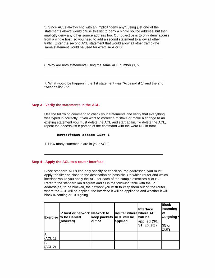
5. Since ACLs always end with an implicit "deny any", using just one of the statements above would cause this list to deny a single source address, but then implicitly deny any other source address too. Our objective is to only deny access from a single host, so you need to add a second statement to allow all other traffic. Enter the second ACL statement that would allow all other traffic (the same statement would be used for exercise A or B:
6. Why are both statements using the same ACL number (1) ?
7. What would be happen if the 1st statement was "Access-list 1" and the 2nd "Access-list 2"?
Step 3 - Verify the statements in the ACL.
Use the following command to check your statements and verify that everything was typed in correctly. If you want to correct a mistake or make a change to an existing statement you must delete the ACL and start again. To delete the ACL, repeat the access-list # portion of the command with the word NO in front.
Router#show access-list 1
1. How many statements are in your ACL?
Step 4 - Apply the ACL to a router interface.
Since standard ACLs can only specify or check source addresses, you must apply the filter as close to the destination as possible. On which router and which interface would you apply the ACL for each of the sample exercises A or B? Refer to the standard lab diagram and fill in the following table with the IP address(es) to be blocked, the network you wish to keep them out of, the router where the ACL will be applied, the interface it will be applied to and whether it will block INcoming or OUTgoing
Exercise IP host or network to be Denied (blocked)
Network to keep packets out of
Router where ACL will be applied
Interface where ACL will be applied (S0, S1, E0, etc)
Block Incoming or Outgoing?
(IN or OUT)
A (ACL 1)
B (ACL 2)
Note: Remember to put Standard ACLs close to the destination
Enter the following commands to apply ACL 1 to interface S1 to block incoming packets on interface S1 for router LAB-D. The real router name (e.g. LAB-D), would appear instead of "Router" in the prompt. For ACL 2, the ACL would be applied to interface E0 on LAB-C for outgoing packets.
Router(config)#interface Serial 1 Router(config-if)#ip access-group 1 in
Step 5 - Verify the ACL is Applied Correctly to the Intended Interface.
Use the following command to check to see that the ACL is applied to the correct interface on the correct router:
Router#show running-config
1. What results were displayed that proves that the ACL is applied correctly?
NOTE: To remove an ACL from an interface, first configure the interface as with step 4 and then repeat the second command with the word NO in front (no ip access-group 1).

Step 6. Verify that the ACL is functioning properly.
Test the ACL by trying to send packets from the source network that is to be permitted or denied. Issue several ping commands to test these ACLs. Several tests are given for each exercise.
Exercise Test# Ping from To Should be successful?
Was it?
A 1 Workstation (192.5.5.2) off router LAB-A
Workstation (210.93.105.2) offrouter LAB-E
2 Workstation (192.5.5.2) off router LAB-A
Router LAB-C Interface S0 (204.204.7.1)
B 1 Workstation (219.17.100.X) off Router LAB-B
Router LAB-E Interface E0 (210.93.105.2) or workstation (210.93.105.X)
2
Workstation (219.17.100.X) off Router LAB-B
Router LAB-C Interface E0 (223.8.151.1)
3 Workstation (219.17.100.X) off Router LAB-B
Workstation (223.8.151.2) off router LAB-C
Lab 6.8.1.1 Extended ACLs - Overview
Estimated time: 60 min.
Objectives:
This Lab will focus on your ability to accomplish the following tasks:
• Review the characteristics and capabilities of extended IP Access Control Lists (ACLs)
• Construct an extended IP ACL to permit or deny specific traffic • Apply an extended IP ACL to a router interface • Test the ACL to determine if the desired results were achieved
Background:
Extended ACLs are a more advanced form of control with more flexibility in the way packets are controlled. Extended ACLs can filter (permit or deny) packets based on source or destination address and on the type of traffic (e.g. FTP, Telnet, HTTP etc.). Since extended ACLs can block traffic based on destination address, they can be placed near the source which helps to reduce network traffic.
In this lab you will work with Extended ACLs to regulate the traffic that is allowed to pass through the router based on the source and type of traffic. ACLs are an important tool to control which packets and what type of packets should be allowed to pass through a router from one network to another.
There are different types of ACLs for different routed protocols such as IP, Novell IPX and AppleTalk. With this lab, you will work only with Extended IP ACLs which are created with a number from 100 to 199.
These are the steps necessary to use ACLs effectively:
1. Determine the ACL requirements (based on company security needs etc.)
2. Construct the ACL. 3. Verify the statements in the ACL 4. Apply the ACL to a router interface. 5. Verify that the ACL is applied correctly to the intended interface. 6. Verify that the ACL is functioning properly
Tools / Preparation:
Prior to starting the lab, the teacher or lab assistant should have the standard router lab with all 5 routers set up. Work individually or in teams. Before beginning this lab you should read the Networking Academy Second Year Companion Guide, Chapter 6 - ACLs. You should also review semester 3 On-line Chapter 6. The following is a list of equipment required.
• Standard Cisco 5-router lab setup with hubs and switches • Workstation connected to the router's console port with a rollover cable

Web Site Resources:
LAN Switching basics General information on all Cisco products - (Scroll down to chapter 15 - Switches) 1900 / 2820 series Ethernet switches 2900 series Fast Ethernet switches Terms and acronyms IP routing protocol IOS command summary Access Control Lists - Overview and Guidelines
Notes:
In this lab you will construct, apply and test an extended IP ACL using the following standard lab setup. You may do either Exercise A or exercise B outlined in Step 1 below.
Step 1 - Determine the ACL Requirements.
Which traffic (packets) will be blocked (denied) or allowed (permitted)? Since you will use an extended IP ACL, you can control not only the source address but also the destination address. You can also pick and choose the specific protocols in the IP protocol suite that you want to allow or prevent from entering the destination network (e.g. TCP. UDP, ICMP, HTTP, Telnet etc.).
Exercise A: Prevent Telnet traffic from a specific host 192.5.5.2 (a workstation off router LAB-A) from reaching an entire network 210.93.105.0 (the network between Routers LAB-D & LAB-E)
Exercise B: Prevent Telnet traffic from a specific host 210.93.105.2 (a workstation off router LAB-E) from reaching an entire network 192.5.5.0 (off Router LAB-A).

Step 2 - Construct the ACL.
Define the ACL statements in Router(config)# mode. ACL statements are additive. Each statement adds to the ACL. If there is more than one statement in the ACL (typical) and you want to change prior statement you must delete the ACL and start again. In these examples you will be blocking packets from only one host IP address or one network based on the destination network and higher level IP protocol (e.g. telnet) being used. The format or syntax of the extended IP ACL statements that you will be using shown below:
access-list list# {permit/deny} [protocol] source IP wildcard mask [port] dest. IP wildcard mask [port] [established] [log] [other options]
(Note: Any number from 100 and 199 can be used for an extended IP ACL)
Complete the ACL command with the correct source and destination address that would accomplish the requirements for either exercise A or B (or both). With extended access-lists, you must also specify the protocol (IP, TCP, UDP, ICMP). Since you are filtering telnet, which uses TCP, remember to include TCP in the command.
Exercise A (ACL 101) access-list 101 deny ____ _________ __________ __________ ________ __________
Exercise B (ACL 102) access-list 102 deny ____ _________ __________ __________ ________ __________
1. Why is the source wildcard mask given as 0.0.0.0?
2. Why is the destination wildcard mask given as 0.0.0.255?
3. What are you checking with the "eq telnet"?
4. What would it mean if you left off the eq telnet?

5. Since ACLs always end with an implicit "deny any", using just one of the statements above would cause this list to deny a single source address, but then implicitly deny any other source address too. Our objective is to only deny access to a single host, so you need to add a second statement to allow all other traffic. Enter the second ACL statement that would allow all other traffic (the same statement would be used for exercise A or B):
Step 3 - Verify the Statements in the ACL.
Use the following command to check your statements and verify that everything was typed in correctly. If you want to correct a mistake or make a change to an existing statement you must delete the ACL and start again. To delete the ACL, repeat the access-list # portion of the command with the word NO in front.
Router#show access-list 101
1. How many statements are in your ACL?
Step 4 - Apply the ACL to a Router Interface.
Because you are now using extended ACLs and can filter on both the source and destination address, you can apply the filter as close to the source as possible, saving on bandwidth. Also remember you can decide to apply the ACL to incoming packets or outgoing packets. Unless IN is specified the ACL will be applied to OUT packets only (IN and OUT are always viewed from outside the router). Which router and which interface would you apply the ACL for each of the sample exercises A or B? Refer to the extended lab diagram and answer the following questions.
Exercise A. 1. On which router, LAB-B or LAB-D, would you apply the filter that would prevent router LAB-A's telnet packets from being transmitted to the D/E LAN (network 210.93.105.0)?
2. On which interface would this list be applied?
3. Complete the commands that would apply this list to that interface:
Router(config)# ___________________________ Router(config-if)# __________________________

Exercise B. 1. On which router, lab-b or lab-d, would you apply the filter that would prevent router LAB-E's packets from being transmitted to the A LAN (network 201.100.11.0)?
2. On which interface would this list be applied?
3. Complete the commands that would apply this list to that interface:
Router(config)#____________________________ Router(config-if)#__________________________
Step 5 - Verify the ACL is Applied to the Correct Interface:
Use the following command to check to see that the ACL is applied to the correct interface on the correct router:
Router#show running-config
1. What results were displayed that proves that the ACL is applied correctly?
NOTE: To remove an ACL from an interface, first configure the interface as with step 4 and then repeat the second command with the word NO in front (no ip access-group 101 in).

Step 6. Verify that the ACL is functioning properly:
Test the ACL by trying to send packets from the source network that is to be permitted or denied. Issue several ping commands to test these ACLs. Several tests are given for each exercise.
Exercise Test # Telnet from To Should be
successful? Was it?
A 1 Workstation(192.5.5.2) off router Lab-A
Workstation (210.93.105.2) offrouter Lan-E
2 Workstation(192.5.5.2) off router Lab-A
Workstation (223.8.151.2) offrouter Lab-C
Exercise Test # Telnet from To Should be
successful? Was it?
B 1 Workstation(210.93.105.2) offrouter Lab-E
Workstation(192.5.5.2) off router Lab-A
2 Workstation(210.93.105.2) off router Lab-E
Workstation (219.17.100.2) offrouter Lab-B
Use the following command with one of the routers where the ACL was applied to verify that packets are being blocked:
Router#show access-list 101
1. What was the result of the command? How could you tell the ACL was working?

Lab 6.8.1.2 Extended ACLs internet - Overview
Estimated time: 90 min.
Objectives:
This Lab will focus on your ability to accomplish the following tasks:
• Design and ACL plan based on specific security requirements • Work with the more advanced capabilities of extended IP Access Control
Lists (ACLs) • Construct an extended ACL with multiple statements • Construct an extended ACL to control Internet traffic using one or more
routers • Construct an extended ACL to permit or deny other specific IP protocol
traffic
Background:
This lab is a practice exercise which simulates a real-world example. You will work with multiple Extended Access Control Lists (ACLs) to simulate regulating the traffic that is allowed to pass through multiple routers to various servers and the Internet. This is primarily a paper-based exercise to practice the analysis of security requirements and design an ACL plan. You can configure the most of the ACLs on the routers indicated in the answer section but you may not be able actually test some of the ACLs filtering capabilities in some cases
Extended ACLs provide a more advanced form of filtering with more flexibility in the way packets are controlled. Extended ACLs can filter (permit or deny) packets based on source or destination address and on the type of traffic (e.g. FTP, Telnet, HTTP etc.). Since extended ACLs can block based on destination address, they can be placed near the source which helps to reduce network traffic.
In this lab you will work with multiple Extended Access Control Lists (ACLs) to regulate the traffic that is allowed to pass through multiple routers based on the source, destination and type of traffic.
These are the steps necessary to use ACLs effectively:
1. Determine the ACL requirements (based on company security needs etc.)
2. Construct the ACL. 3. Verify the statements in the ACL 4. Apply the ACL to a router interface. 5. Verify that the ACL is applied correctly to the intended interface. 6. Verify that the ACL is functioning properly

Tools / Preparation:
This is primarily a paper-based practice exercise but access to the 5 router labs is desirable. A white board should be available to brainstorm the different ways to provide the required security. Work in teams of 2 or 3. Before beginning this lab you should read the Networking Academy Second Year Companion Guide, Chapter 6 - ACLs. You should also review semester 3 On-line Chapter 6. The following is a list of equipment required.
• Standard Cisco 5-router lab setup with hubs and switches • Workstation connected to the router's console port with a rollover cable
Web Site Resources:
LAN Switching basics General information on all Cisco products - (Scroll down to chapter 15 - Switches) 1900 / 2820 series Ethernet switches 2900 series Fast Ethernet switches Terms and acronyms IP routing protocol IOS command summary Access Control Lists - Overview and Guidelines
Notes:
In this lab you will design a security plan using multiple extended ACLs and determine where they should be applied based on the following standard router lab setup below. There is more than one correct answer.
Start with the standard lab setup shown in the overview and then draw a detailed diagram of all routers, servers and networks to help work out the requirements. Use the space provided on the next page to diagram the requirements listed below and help determine what ACLs are needed and where they should go.
Step 1 - Define the ACL Requirements:
The requirements and some assumptions for this lab are given below. In general it is best to try to use the fewest access-lists possible while minimizing network traffic and allowing for potential network growth. You will use extended ACLs for this exercise.

Assume your enterprise servers are located on network 219.17.100.0 (off LAB-B).
1. Allow everyone Web access (http protocol) to your web server 219.17.100.80
2. Allow everyone DNS access to your DNS server 219.17.100.53 3. Allow faculty from network 223.8.151.0 full access to any of these
servers. 4. Allow no other access to any server on the 219.17.100.0 network
Assume students are all on network 210.93.105.0, and control access to or from their network. Assume router Lab-A belongs to your ISP and you do not have control over it.
1. Do NOT allow students to use FTP to the Internet (virus alert!) 2. Allow students all other access to the Internet 3. Permit student access to the faculty network 223.8.151.0 for email
(SMTP) 4. Deny all other student access to the faculty network 223.8.151.0
Step 2 - Construct one or more ACLs.
Group the statement above based on common characteristics and where you think the ACL should be applied. Try to create the fewest ACLs possible and still be flexible. The format or syntax of the extended IP ACL statements that you will be using is shown below:
access-list list# {permit/deny} [protocol] source IP wildcard mask [port] dest. IP wildcard mask [port] [established] [log] [other options]
(Note: Any number from 100 and 199 can be used for an extended IP ACL)
Step 3 - Apply and Check the ACLs with lab routers (if available).
If you have access to the routers in the lab you can apply and check the ACLs you have created. You may not be able to test all of the ACL filtering capabilities since you will not have an HTTP or DNS server or access to the Internet but you can test most of the filtering. Remember that only one ACL can be applied per protocol (such as IP) per direction (IN or OUT).

Diagram the routers and servers and show the location of ACLs (router and interface, in or out) based on the security requirement.

Lab 7.4.3 IPX routing - Overview
Estimated time: 90 min.
Objectives:
This Lab will focus on your ability to accomplish the following tasks:
• To become familiar with Novell NetWare IPX protocol and its use in Internetworks
• To configure the lab routers to route the Novell IPX protocol as well as IP
• To provide support for NetWare clients and servers which are running IPX
Background:
In previous labs you have been working with the TCP/IP routed protocol or the Internet Protocol (IP). In this lab you will work with Novell’s Internetwork Packet Exchange (IPX) routed protocol. OSI layer 3 protocols such as IP and IPX contain information in their packets to indicate what network the packet came from and what network it is going to. Routable protocols (such as IP and IPX) are those protocols that are capable of allowing packets to be routed between networks and enable them to get from one location to another. Routers can run multiple routing (e.g. RIP or IGRP) and routed (IP and IPX) protocols. In order to be able to route both IP and IPX the router must maintain multiple routing tables, one for each type of routed protocol being supported.
Novell's IPX/SPX Implementation
IPX is a proprietary routed protocol developed by Novell Inc. for use with its NetWare Network Operating System. It is very widely used with private Local and Wide Area Networks having Novell NetWare servers. Earlier versions of NetWare (3.x and most 4.x versions) used IPX as their primary protocol. In order to support these servers it is necessary to run the IPX protocol on routers, servers and workstations. Newer versions such as NetWare 5.0 can use IP natively. It is possible to have a multi-router Novell network using only the IPX protocol but IP is still required to access the Internet. IPX does not support subnets and cannot be routed over the Internet
The Novell network operating system uses 2 main protocols, IPX and SPX, to help ensure delivery of packets. IPX is responsible for layer 3 routing to get packets from one network to another. Sequential Packet Exchange or SPX is a connection oriented packet delivery protocol similar to TCP. There are 2 parts to an IPX address; a network portion and a host portion. The network portion of the IPX address is a 32 bit hexadecimal number and the host portion is the 48-bit MAC address of the NIC (for the server, workstation etc). Since the host or node address is its MAC address, it is not necessary to assign a host address as with IP. ARP is not required since the MAC address is known

Tools / Preparation:
Prior to starting the lab, the teacher or lab assistant should have the standard router lab with all 5 routers set up. Before beginning this lab you should read the Networking Academy Second Year Companion Guide, Chapter 7 - Novell IPX. You should also review semester 3 On-line Chapter 7. The following is a list of equipment required:
• Standard Cisco 5-router lab setup with hubs and switches • Workstation connected to the router's console port • Console Cable (roll-over)
Web Site Resources:
Routing basics General information on routers 2500 series routers 1600 series routers Terms and acronyms Routing Novell IPX Troubleshooting Novell IPX Novell IPX Commands
The following IOS IPX-related commands will help with IPX connectivity information and troubleshooting:
IPX Connectivity / Troubleshooting Commands
Show ipx interface Shows the status of IPX interfaces and IPX configured parameters (frame type) on each interface
Show ipx route Displays the contents of the IPX routing table with known IPX networks
Show ipx servers Lists the Novell servers running IPX which are discovered through SAP advertisements
Show ipx traffic Shows IPX traffic information including the number and type of IPX packets transmitted and received by the router
Debug ipx routing activity Displays dynamic information about IPX routing update packets that are transmitted and received (every 60 sec.)
Debug ipx sap Displays dynamic about IPX Service Advertising Protocol (SAP) packets that are transmitted or received
Ping Use extended version (ping then press enter) to specify an IPX node address.

Step 1 - Determine the Number of Networks Needed.
How many IPX networks will you need (LAN and WAN networks) for our 5-router lab?
(Refer to the standard 5-router diagram. How many IP networks are there?)
Step 2 - Review Proper IPX Addressing.
Review the structure of the IPX addressing scheme and answer the following questions:
1) Would 6F be a valid IPX network number?
Why or why not?
(hint: are IPX network numbers represented in decimal or in Hex?)
2) Would 1a2b3c4d5e be a valid IPX network number?
Why or why not ?
(hint: how long are IPX network numbers? How many bits? How many hex digits is that?)
Step 3 - Enable IPX Routing.
Use the following command to enable IPX routing for each router. This enables IPX RIP and SAP. After enabling IPX on the router and while still in IPX configuration mode, go to step 4 and select the interfaces that will route IPX and assign them network numbers.
Router(config)# ipx routing

Step 4 - Create IPX Network Numbers:
Use the standard 5-router diagram as a guide for creating unique network numbers for each "wire" or network. Fill in the table below with the model number of each router and the IPX network addresses you will use. Not all routers will have or use all of the interfaces shown. Remember that serial interfaces between two routers will share the same network number. Hexadecimal IPX network numbers can contain numbers 0 thru 9 and letters A thru F and can range from 1 to FFFFFFFF.
Router Name
Model Number Ethernet 0 IPX Network
Ethernet 1 IPX Network
Serial 0 IPX Address
Serial 1 IPX Address
Lab-A Lab-B Lab-C Lab-D Lab-E
Step 5 - Assign IPX Network Numbers to Interfaces.
On each interface on each router, configure the IPX network number from the table above:
Router(config)# interface E0 (Selects the Ethernet interface E0) Router(config-if)# ipx network A2C (A2C = unique IPX network number)
Step 6 - Check for redundant paths.
1) Are there any redundant paths in our lab? That is, are there two or more ways for packets to get from one place to another?
2) If there are redundant paths (2), and you want IPX traffic load sharing over those 2 possible paths, you need to tell the router to accept multiple paths. Complete the command you would use:
Router(config)# ipx
Step 7 - Check Routing Tables.
Since IPX RIP is automatically enabled when you enable IPX routing, you can now check each router's routing table to verify that all routers have learned all of the IPX networks:
Router# show ipx route

Step 8 - Telnet to a Neighboring router.
Telnet to another router and issue a show running-config command to see which interfaces are in use. Use the following command to find the IPX address of one of the Ethernet interfaces.
Router# show ipx interface e0 1) What was the IPX address of the interface?
2) What portion is the network address?
3) What portion is the interface MAC address?
Step 9 - Ping the Neighboring Router Interface.
Return to the router you were on and issue the ping command, remembering to use a dot between the network number and the MAC address, and after every 4 digits of the MAC address. Enter a sample IPX ping command here.
Router# ping ipx
Step 10 - Reflection:
In your journal write about the differences between IPX and IP routing tables.