Ccna Guide
157
CCNA Complete Guide 2nd Edition Yap Chin Hoong CCNA
-
Upload
karim-armani -
Category
Documents
-
view
217 -
download
7
Transcript of Ccna Guide

CCNA Complete Guide 2nd Edition
Yap Chin Hoong CCNA
CCNA Complete Guide 2nd Edition Copyright © 2008 Yap Chin Hoong
Chapter Title Page
Chapter 1 Introduction to Computer Networking (Lecture) 1
Chapter 2 Transport and Network Layers (Lecture) 7
Chapter 3 Data Link and Physical Layers featuring The Ethernet (Lecture) 17
Chapter 4 Introduction to Cisco IOS (Lab) 31
Chapter 5 Spanning Tree Protocol (Lecture) 39
Chapter 6 Spanning Tree Protocol Lab (Lab) 45
Chapter 7 Virtual LAN and VLAN Trunking Protocol (Lecture) 51
Chapter 8 Virtual LAN and VLAN Trunking Protocol Lab (Lab) 57
Chapter 9 IP Addressing and Subnetting (Lecture) 61
Chapter 10 IP Addressing and Subnetting Exercise (Lecture) 65
Chapter 11 Managing a Cisco Internetwork (Lab) 67
Chapter 12 Distance-Vector Routing Protocols – RIP and IGRP (Lecture) 75
Chapter 13 Static Routing, Default Routing, RIP, and IGRP Lab (Lab) 81
Chapter 14 OSPF and EIGRP (Lecture) 91
Chapter 15 OSPF and EIGRP Lab (Lab) 99
Chapter 16 Variable-Length Subnet Masks and Route Summarization (Lecture + Lab) 111
Chapter 17 Classful and Classless Routing, and MISC TCP/IP Topics (Lecture + Lab) 117
Chapter 18 Scaling the Internet with CIDR and NAT (Lecture) 123
Chapter 19 Network Address Translation Lab (Lab) 131
Chapter 20 IP Access Control Lists (Lecture) 135
Chapter 21 IP Access Control Lists Lab (Lab) 139
Chapter 22 WAN Basics, Remote Access Technologies, and Serial PPP (Lecture) 143
Chapter 23 Serial PPP Connections Lab (Lab) 153
Chapter 24 Frame Relay (Lecture) 157
Chapter 25 Frame Relay Lab (Lab) 165
Chapter 26 Wireless Networking (Lecture + Lab) 173
Bonus Chapters:
Chapter 27: ISDN (Page 187)
Chapter 28: ISDN and Dial-on-Demand Routing Lab (Page 193)
Chapter 29: Route Redistribution (Page 203)
Appendix 1: Cisco IOS Upgrade and Password Recovery Procedures (Page 207)
Appendix 2: Frame Relay Switch Configuration (Page 219)
Appendix 3: The IP Routing Process (Page 225)
Appendix 4: Dissecting the Windows Routing Table (Page 229)
Appendix 5: Decimal-Hex-Binary Conversion Chart (Page 231)
Appendix 6: CCNA Extra Knowledge (Page 235)

Copyright © 2008 Yap Chin Hoong
7
Chapter 2
Transport and Network Layers
Transport Layer
- Transport layer protocols provide reliable and unreliable application data delivery services.
The Transmission Control Protocol (TCP) and User Datagram Protocol (UDP) are the most
common transport layer protocols. There are many differences between them.
Figure 2-1: Connection-Oriented Session Establishment
- Connection-oriented communication is used in reliable transport service – TCP. Figure 2-1
shows the TCP connection establishment sequence (also known as three-way handshake) which
allows the systems to exchange information such as initial sequence number, window size, and
other TCP parameters for reliable data transfer between a web browser (client) and a web server.
These steps must be completed prior to data transmission in connection-oriented communication.
- The SYN and ACK flags are very important for the connection-oriented session establishment.
When SYN bit is set, it means synchronize the sequence numbers (during connection setup),
while ACK bit is used to indicate that the value in the acknowledgment field is valid. In step 2,
the ACK replied by the web server acknowledges the receipt of the web browser’s SYN message.
- Figure 2-2 shows the TCP connection termination sequence to gracefully shutdown a connection.
An additional flag – FIN flag, is being used in the four-way connection termination sequence.
Firstly, the web server sends a segment with the FIN bit set to 1 when the server application
decided to gracefully close the connection after finished sending data (Step 1). The client would
then reply with an ACK reply, which means it notices the connection termination request (Step 2).
After that, the server will still wait for FIN segment from the client (Step 3). Finally, the server
acknowledges the client’s FIN segment (Step 4).
Figure 2-2: TCP Connection Termination
Copyright © 2008 Yap Chin Hoong
8
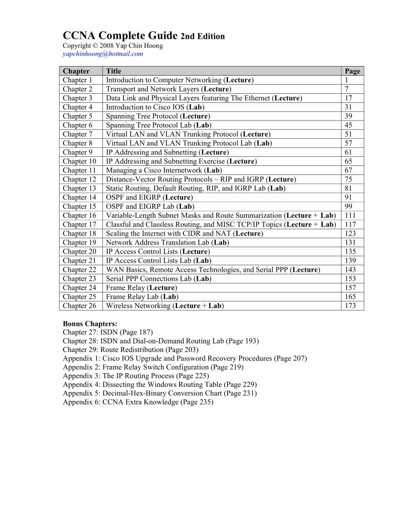
Figure 2-3: TCP Segment Structure
- Sequence Number is used by TCP to segment large application layer data into smaller pieces.
Every TCP segment sent over a TCP connection has a sequence number, which represents the
byte-stream number relative to the 1st byte of the application layer data.
Acknowledgment Number is the sequence number of the next expected bytes. It is used by the
receiver to tell the sender the next byte to send (or resend). The acknowledgment mechanism is
accumulative – a packet with the ACK bit set and an acknowledgment number of x indicates that
all bytes up to x – 1 have been received.
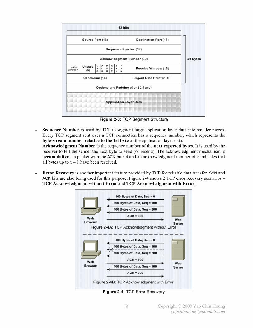
- Error Recovery is another important feature provided by TCP for reliable data transfer. SYN and
ACK bits are also being used for this purpose. Figure 2-4 shows 2 TCP error recovery scenarios –
TCP Acknowledgment without Error and TCP Acknowledgment with Error.
Figure 2-4: TCP Error Recovery

Copyright © 2008 Yap Chin Hoong
9
- In Figure 2-4B, the 2nd segment is lost. In order to recover the lost segment, the web client
replies a segment with acknowledge number equal to 100, which means it expecting byte number
100 from the web server. The server then resends the data to the client (retransmission). Since
the client has already received bytes 200-299 without error, it is not necessary to request again.
Data is then reassembled back in order at the client end and passed to the application layer.
Finally, the client continues to request data from the web server by sending an ACK = 300.
- Positive Acknowledgment and Retransmission (PAR) uses a timer that is set to the
retransmission timeout interval and is being activated every time a sender sends a segment and
waiting for the ACK reply. The sender will resend all segments once the timer expired. This
provides a reliability mechanism that intends to overcome the following 2 problem scenarios:
i) The transmitted segment is lost or dropped.
ii) The ACK segment is failed to arrive at the sender.
- TCP segments may arrive out of order because routers can send data across different links to a
destination host. Hence the TCP stack running at the receiving end must reorder the out of order
segments before passing the data to the application layer.
- TCP Flow Control or Congestion Control provides a mechanism for the receiver to control the
sending rate of the sender with a windowing mechanism. It is achieved via SEQ, ACK and
Window fields in the TCP header. The receiver defines the Window size to tell the sender how
many bytes are allowed to send without waiting for an acknowledgement. It represents the
receiver’s available buffer. Buffer is used to temporarily store the received bytes before the
receiving application is free to process the received bytes. The sender will not send when the
receiver’s window is full. Increased Window size may result in increased throughput.
- The window size normally starts with small value and keeps on increment until an error occurs.
The window size is negotiated dynamically throughout a TCP session and it may slide up and
down, hence it is often being referred to as sliding window.
- Multiplexing allows multiple connections to be established between processes in 2 end systems.
Multiplexing is a feature that allows the transport layer at the receiving end to differentiate
between the various connections and decide the appropriate application layer applications to
hand over the received and reassembled data (similar to the concept of forming virtual circuits).
The source and destination port number fields in the TCP and UDP headers and a concept
called socket are being used for this purpose.
- Below lists some popular applications and their associated well-known port numbers:
Application Protocol Port Number
HTTP TCP 80
FTP TCP 20 (data) and 21 (control)
Telnet TCP 23
TFTP UDP 69
DNS TCP, UDP 53
DHCP UDP 67, 68
SMTP TCP 25
POP3 TCP 110
SNMP UDP 161
- Port numbers 0 – 1023 are well-known ports, port numbers 1024 – 49151 are registered ports,
and port numbers 49152 – 65535 are private vendor assigned and dynamic ports.

Copyright © 2008 Yap Chin Hoong
10
- Socket is a communication channel between 2 TCP processes. A client socket is created by
specifying the IP address and the destination port to connect to the server; whereas a server
socket binds to a specified port number and listens for incoming connections upon started a
server application.
- User Datagram Protocol (UDP) is a connectionless (does not contact the destination before
data transmission) and unreliable data delivery service, which also known as best effort service.
No sequencing. No reordering. No acknowledgment. No error recovery. No congestion control.
- Applications uses UDP are either tolerant to data lost, or perform error recovery themselves
(perform error recovery in application layer instead of transport layer).
i) Tolerant to data lost: video streaming.
ii) Handles its own reliability issues: NFS and TFTP (hence the use of TCP is unnecessary)
- Figure 2-5 shows the UDP segment structure. It does not contain SEQ, ACK and other fields as in
TCP header. Even there are many disadvantages as mentioned above, UDP advantages over TCP
are it is faster (no ACK process) and uses less network bandwidth and processing resources.
Figure 2-5: UDP Segment Structure
- In network programming, a socket would fail to bind to specified port if the port is already in use
by another socket. However, a host is allowed to bind a TCP socket and a UDP socket to the
same port number at the same time, and waiting for incoming connections, as they are treated
as 2 different type of service – a host can provide TCP and UDP Echo services at the same time.
- Do not make false assumption that connection-oriented = reliable!
A connection-oriented protocol does not mean it also performs error recovery, and vice-versa.
Connection Type Reliable Example Protocol
Connection-oriented Yes TCP
Connection-oriented No TP0 and TP2
Connectionless Yes TFTP and NFS
Connectionless No UDP
Note: TPx isTransport Protocol Class x in ISO-TP (OSI Transport Layer Protocols).
- Below shows the TCP and UDP comparison chart:
Feature TCP UDP
Connection-oriented Yes No
Reliable data transfer Yes No
Ordered data transfer Yes No
Flow control Yes No
Multiplexing Yes Yes
Copyright © 2008 Yap Chin Hoong
11
Network Layer
- The main functions performed by network layer (L3) protocols are routing and addressing.
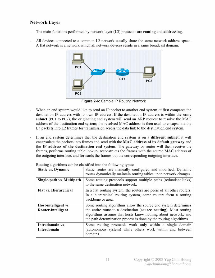
- All devices connected to a common L2 network usually share the same network address space.
A flat network is a network which all network devices reside in a same broadcast domain.
Figure 2-6: Sample IP Routing Network
- When an end system would like to send an IP packet to another end system, it first compares the
destination IP address with its own IP address. If the destination IP address is within the same
subnet (PC1 to PC2), the originating end system will send an ARP request to resolve the MAC
address of the destination end system; the resolved MAC address is then used to encapsulate the
L3 packets into L2 frames for transmission across the data link to the destination end system.
- If an end system determines that the destination end system is on a different subnet, it will
encapsulate the packets into frames and send with the MAC address of its default gateway and
the IP address of the destination end system. The gateway or router will then receive the
frames, performs routing table lookup, reconstructs the frames with the source MAC address of
the outgoing interface, and forwards the frames out the corresponding outgoing interface.
- Routing algorithms can be classified into the following types:
Static vs. Dynamic Static routes are manually configured and modified. Dynamic
routes dynamically maintain routing tables upon network changes.
Single-path vs. Multipath Some routing protocols support multiple paths (redundant links)
to the same destination network.
Flat vs. Hierarchical In a flat routing system, the routers are peers of all other routers.
In a hierarchical routing system, some routers form a routing
backbone or area.
Host-intelligent vs.
Router-intelligent
Some routing algorithms allow the source end system determines
the entire route to a destination (source routing). Most routing
algorithms assume that hosts know nothing about network, and
the path determination process is done by the routing algorithms.
Intradomain vs.
Interdomain
Some routing protocols work only within a single domain
(autonomous system) while others work within and between
domains.

Copyright © 2008 Yap Chin Hoong
12
- The length of an IP address is 32-bit or 4 bytes, and usually written in dotted-decimal notation,
where each byte (8 bits) of the 32-bit IP address is converted to its decimal equivalent. Each of
the decimals numbers in an IP address is called an octet.
Ex: IP address = 192.168.0.1. 1st octet = 192, 2nd octet = 168, 3rd octet = 0, and 4th octet = 1.
- Each network interface in an end system will be assigned a unique IP address.
- Network layer addresses were designed to allow logical grouping of addresses.
TCP/IP network or subnet
IPX network
AppleTalk cable range
- IP addressing and grouping of IP addresses ease the routing process by assisting routers in
building their routing tables. The general ideas of IP addresses grouping are:
• All IP addresses in the same group must not be separated by a router.
• IP addresses separated by a router must be in different groups.
- IP subnetting allows the creation of larger numbers of smaller groups of IP addresses, instead of
simply using the class A, B, and C conventional rules. Subnetting treats a subdivision of a single
class A, B, or C network as a network itself – a single class A, B, or C network can be
subdivided into many smaller groups and non-overlapping subnets.
- When performing subnetting, the subnet portion or mask (a part of between the network and host
portions of an address) is created by borrowing bits from the host portion of the address.
The size of the network portion never shrinks while the size of the host portion shrinks to make
room for the subnet portion of the address. Figure 2-7 shows the address format when subnetting.
Figure 2-7: Address Formats when Subnetting
- Subnet masks are used in conjunction with IP addressing to define which subnet an IP address
(in fact, an end system) resides in by identifying the network and host bits for the IP address.
Routers only examine the network bits in an IP address as indicated by the subnet mask – the
network address, when performing its function – examine network address, lookup network
address in the routing table, and forward the packet out the corresponding outgoing interface.

Copyright © 2008 Yap Chin Hoong
13
Figure 2-8: IPv4 Datagram Format
- The Identification, Flags, Fragmentation Offset fields are used for IP fragmentation – the
process of breaking large packets that exceed the MTU of the intermediate network medium into
smaller datagrams called fragments. Network layer fragments are reassembled before they are
being passed to the transport layer at the receiver. IPv6 does not support fragmentation at routers.
Fragmentation can result in degradation of router performance due to the additional workloads.
- The Protocol field identifies the transport layer protocol (eg: TCP, UDP) or network layer
protocol (eg: ICMP, ARP) the packet payload (the data portion of datagram) should be passed to.
- Checksum is a test for ensuring the integrity of data. It is a number calculated from a sequence
of mathematical functions. It is typically placed at the end of the data from which it is calculated,
and then recalculated at the receiving end for verification (error detection).
- IP does not run complete checksum upon the whole packet as what Ethernet does upon a frame.
The Header Checksum field in the IPv4 header is a checksum that is calculated based on all the
fields in the IPv4 header only; hence only the IPv4 header is being checked for errors.
The Header Checksum field is filled with 0s when computing the checksum.
- Below are some popular protocols that can be specified in the Protocol field:
Protocol Protocol Number
ICMP (Internet Control Message Protocol) 1 (0x01)
TCP (Transmission Control Protocol) 6 (0x06)
IGRP (Interior Gateway Routing Protocol) 9 (0x09)
UDP (User Datagram Protocol) 17 (0x11)
EIGRP (Enhanced IGRP) 88 (0x58)
OSPF (Open Shortest Path First) 89 (0x59)
IPv6 (IP Version 6) 41 (0x29)
GRE (Generic Routing Encapsulation) 47 (0x2F)
ESP (Encapsulating Security Payload) 50 (0x32)
AH (Authentication Header) 51 (0x33)
L2TP (Layer 2 Tunneling Protocol) 115

Copyright © 2008 Yap Chin Hoong
14
- The following section discusses several TCP/IP network layer utility protocols.
- Address Resolution Protocol (ARP) � When IP (L3) has a packet to send, it must supply the
destination host’s hardware address to a network access protocol, eg: Ethernet or Token Ring.
IP will first try to find the information from the ARP cache. If IP is unable to find it from the
ARP cache, it uses ARP to dynamically discover or learn the MAC address for a particular IP
network layer address. A sender must know the physical or MAC address of the destination host
before sending out the data. Basically ARP resolves an IP address (software logical address) to a
MAC address (hardware physical address).
- ARP Requests are L2 broadcasts. Since Ethernet is a broadcast media, hence all devices on a
segment will receive an ARP Request. However, only the device with the requested L3 address
will answer the ARP Request by sending a unicast ARP Reply back to the device that sent the
ARP Request. The sender will then have the IP and MAC addresses for data transmission.
Note: The sender might need to send out DNS request to resolve the hostname of the destination
host into IP address prior to the ARP Request-Reply process.
- Hubs and repeaters are typically signal amplifiers, while switches do forward broadcasts out all
ports except the incoming port. In fact they have no impact on ARP traffic.
- The show arp EXEC command displays the entries in the ARP cache.
- Proxy ARP happens when a network device replies to an ARP Request on behave of another
device with the MAC address of the interface that received the ARP Request. The ARP caches of
end systems might need to be flushed (with the arp –d command) whenever a Proxy ARP
device is being introduced into a network.
Figure 2-9: Network Setup for Proxy ARP
- Routers do not forward L2 and L3 broadcasts. Figure 2-9 shows a typical Proxy ARP scenario.
Since PC1 and PC2 IP addresses are reside in the same subnet (10.1.0.0/16), PC1 will assume it
is in the same segment with PC2. Problems arise as there is a router separates the 2 devices into
different broadcast domains, which the ARP broadcast traffic will not be forwarded.
- RT1, the Cisco router will answer the ARP Request sent by PC1 on behave of PC2 with the MAC
address of the interface that received the ARP Request – BB-BB-BB-BB-BB-BB. When PC1
receives the ARP Reply from RT1, it assumes the MAC address of PC2 is BB-BB-BB-BB-BB-BB.
Finally, further traffic destined to PC2 will have 10.1.2.2 as the destination IP address and
encapsulated with the MAC address BB-BB-BB-BB-BB-BB instead of DD-DD-DD-DD-DD-DD.
- Proxy ARP is enabled by default on Cisco routers. It can be enabled or disabled with the [no] ip
proxy-arp interface subcommand respectively. Proxy ARP is not really a protocol; it is a
service offered by routers.
Copyright © 2008 Yap Chin Hoong
15
- Reverse ARP (RARP), Boot Protocol (BOOTP) and Dynamic Host Configuration Protocol
(DHCP) allow a host computer to discover the IP address it should use.
- RARP and BOOTP requests which are sent out as broadcasts would include a host MAC
address to request for an IP address assigned to that MAC address. RARP is only able to ask for
an IP address, it can’t even ask for the subnet mask; whereas BOOTP which was defined later,
allows many more information to be announced to a BOOTP client, eg: IP address, subnet mask,
default gateway, other servers IP addresses, and the name of the file the client computer should
download (a more sophisticated OS) into the client computer’s RAM. Both protocols were
created to allow diskless workstations to initialize, boot up, and start operating once turned on.
- However, both protocols are not in use today as an RARP or BOOTP server is required to know
all computers MAC addresses – a MAC-to-IP-address mapping table, and the corresponding
configuration parameters for each computer, which is a nightmare of network administration.
- Dynamic Host Configuration Protocol (DHCP), which is widely used in today’s networks,
solves the scaling and configuration issues in RARP and BOOTP. DHCP uses the same concept
of BOOTP – a client makes a request, the server supplies the IP address, subnet mask, default
gateway, DNS server IP address, and other information. The biggest advantage of DHCP is a
DHCP server does not need to be configured with the MAC-to-IP-address mapping table.
- ARP and RARP are network and data link layer protocols whereas DHCP and BOOTP are
application layer protocols.
- Inverse ARP (InARP) doesn’t deal with IP and MAC addresses. It is used to dynamically create
the mapping between local DLCIs and remote IP addresses in Frame Relay networks. However,
many organizations prefer to statically create those mappings. This default behavior can be
disabled with the no frame-relay inverse-arp interface subcommand.
- Internet Control Message Protocol (ICMP) is a management and control protocol for IP. It is
often used by hosts and routers to exchange network layer information and problem notification.
ICMP messages are encapsulated within IP packets and sent using the basic IP header only.
- Hops or TTL (Time-to-Live) � Each IP packet needs to pass through a certain number of
routers (hops) before arrive to the destination. When a packet reaches its limit of existence in the
network (TTL expired) before arrives to its destination, the last router that receives the packet
will discard it, and sends an ICMP message to the sender to inform the dropping of its packet.
This mechanism is used to prevent IP packets from being forwarded forever upon routing loops.
- ping (Packet INternet Groper) is a basic network utility that uses ICMP to test for physical and logical network connectivity by sending out an ICMP Echo Request message to an IP address,
and expects the end system with that IP address will reply with an ICMP Echo Reply message.
The ICMP identifier, sequence number, and data received in an Echo Request message must be
returned unaltered in the Echo Reply message to the sender.
- Traceroute is another network utility that is being used to discover the path to a remote host by
utilizing ICMP Time Exceeded messages.

Copyright © 2008 Yap Chin Hoong
39
Chapter 5
Spanning Tree Protocol
- Most network engineers design LANs with redundant links between switches in order to provide
higher availability as switch hardware and cable problems might occur.
- Broadcast frames could loop forever in networks with redundant links – broadcast storm.
Switching or bridging loops might caused by broadcast of ARP requests for locating an unknown
or shutdown device, as switches were designed to forward unknown unicast frames.
- Another problem is multiple frame copies, which could occur when a frame arrives from
different segments at the same time, which could also lead to MAC address table thrashing.
- Spanning Tree Protocol (STP) was introduced to solve these problems by placing switch ports
in either forwarding or blocking state in forming a single active path called the spanning tree.
The purpose of STP is to maintain a loop-free network topology in networks with redundant
links. STP is enabled by default in Cisco Catalyst switches.
- Switch ports in forwarding state can receive and forward frames.
Switch ports in blocking state cannot receive and forward frames (but can still receive BPDUs).
Note: If a blocking state port can receive frames, it will process and forward broadcast frames!
Figure 5-1: Network Setup for Spanning Tree Protocol
- Figure 5-1A shows a network after the STP convergence – SW3’s Fa0/2 port is in blocking state.
When PC1 sends a broadcast frame, SW1 will forward the broadcast frame to both SW2 and
SW3. SW2 can forward the frame to SW3 as its Fa0/2 port is in forwarding state; whereas SW3
cannot forward the frame to SW2 as its Fa0/2 port is in blocking state.
- When the link between SW1 and SW3 fails (Figure 5-1B), SW3 will react as it no longer
receiving any BPDU via its root port (Fa0/1). After the STP convergence, SW3 Fa0/2 will be
changed to forwarding state, which allows SW3 to exchange frames with other switches.
- The drawback of STP is it would cause some frames to traverse a longer and less-efficient path.
Ex: If PC3 wants to send a frame to PC2, the frame will be traversed from SW3 � SW1 � SW2.

Copyright © 2008 Yap Chin Hoong
40
- Below describes the STP convergence process:
i) Elect the root bridge. There is only one root bridge per network. All root bridge’s ports
(which are also designated ports) are placed in forwarding state.
ii) Selects the root port on all non-root bridges. Root port is the port that is closest to the
root bridge, which means it is the port that receiving the lowest-cost BPDU from the root.
Every non-root bridge must have a root port. All root ports are placed in forwarding state.
Note: It is not always the shortest path but the fastest path to reach the root bridge.
iii) Selects the designated port from the designated bridge for each LAN segment.
Designated bridge is the lowest-cost bridge on each segment that forwards the lowest-
cost BPDUs into the segment. If the costs are the same, the port of the lower BID bridge
will be selected as the designated port. If there is a tie in the BID, the port with the lowest
port ID will be used as the final tiebreaker (this happens when a switch connects back to
itself with a cross cable). All designated ports are placed in forwarding state.
iv) All other ports – non-designated ports, are placed in blocking state.
- STP root bridge election process started with each bridge claiming itself as the root bridge by
sending out multicast frames called Bridge Protocol Data Units (BPDUs), which are used to
exchange STP information between bridges. A BPDU contains the following important values:
The Bridge IDs of the
Root Bridge and the
Transmitting Bridge
BID is an 8-byte field that is composed of the bridge priority value
(0-65535, 2 bytes) and the bridge MAC address (6 bytes). The root
bridge is the bridge with the lowest bridge ID. A bridge can become
the root bridge by lowering the priority value (eventually the BID),
which is normally being practiced in large switched networks.
The cost to reach the
root from this bridge
(Root Path Cost)
This value is set to 0 at the beginning of STP root bridge election
process since all bridges claim to be the root. The lower the cost, the
better chance to become a designated port. The range is 0-65535.
Port ID The port ID of the originating switch port of the BPDU frame.
- The bridge with the lowest priority becomes the root. 32768 is the default bridge priority value.
If there is a tie occurred on priority, the bridge with the lowest MAC address becomes the root.
Figure 5-2: Root Bridge Election
- Figure 5-2 shows the STP root bridge election process. Each switch sends out BPDUs to claim
itself as the root. Assume that SW2 receives the BPDU from SW1 faster than SW3, SW2 agrees
that SW1 is the root and start forwards out SW1 BPDUs to SW3 with the accumulated cost.
After a while, SW3 will also agree that SW1 is the root bridge after received BPDU from SW1.

Copyright © 2008 Yap Chin Hoong
41
Figure 5-3: Electing the Designated Port
- SW2’s Fa0/2 port will be selected as the designated port for the segment between SW2 and
SW3 even both switches forward the same cost BPDUs into the segment, because SW2 has the
lower BID (same priority but lower MAC address) than SW3. Below lists the state of all switch
ports after the STP convergence:
Port State Why Is It In Forwarding State
SW1, Fa0/1 Forwarding Root bridge’s interface.
SW1, Fa0/2 Forwarding Root bridge’s interface.
SW2, Fa0/1 Forwarding Root port.
SW2, Fa0/2 Forwarding Designated port for the segment between SW2 and SW3.
SW3, Fa0/1 Forwarding Root port.
SW3, Fa0/2 Blocking –
- Below list the default IEEE STP port costs:
Speed Port Cost
10Gbps 2
1Gbps 4
100Mbps 19
10Mbps 100
- In a stable topology, the root bridge will be continuously generating BPDUs every 2 seconds.
Other bridges will change the Root Path Cost in the received BPDUs to the accumulated cost of
the particular bridge to the root and propagate the BPDUs out their designated ports.
Ex: A root bridge will send out BPDUs with Root Path Cost of 0. A non-root bridge that
connects to the root bridge via Fast Ethernet will send out BPDUs with Root Path Cost of 19.
- A bridge assumes the path to the root is active by constantly receiving BPDUs from the root. A
non-root bridge will declare itself as the root bridge if it does not receive the BPDUs from the
root for the MaxAge period, which could be caused by the spanning-tree bpdufilter enable
interface subcommand that configures an interface to not send and receive (ignore) BPDUs.
- A BPDU also defines the following timers:
Hello Time The time a root bridge should wait before sending out periodical BPDUs.
The default interval is 2 seconds.
MaxAge The time a bridge should wait before trying to change the STP topology after it
fails to receive the BPDUs from the root. The default interval is 20 seconds.
Forward
Delay
The time a bridge should spend for the listening and learning states when an
interface needs to be changed from blocking to forwarding state. The default
interval for both states is 15 seconds.

Copyright © 2008 Yap Chin Hoong
42
- Refer back to Figure 5-1B, assume the Metro Ethernet WAN link between SW1 and SW3
experiencing problems and frames (including BPDUs) are unable to traverse across the link even
the interface and line protocol are active, SW3 will react after it fails to receive the BPDUs from
SW1 for the MaxAge period. SW2 does not react since it still can receive the BPDUs from SW1.
- SW3 will declare itself as the root bridge and start generating BPDUs after its MaxAge expires.
However, it will receive a better BPDU (SW1 root bridge BPDUs) from SW2. SW3’s Fa0/2 will
become the root port and transitioned from blocking to forwarding state (after the listening and
learning states). SW3 will send out a TCN BPDU out Fa0/2 when Fa0/2 is transitioned to
forwarding state in order to inform the root bridge regarding the spanning tree topology change.
- A switch port cannot be immediately transitioned from blocking state to forwarding state, as
broadcast storms (due to switching loop) could occur if other switches were also converging.
STP uses the following 2 intermediate (or transition) states to prevent switching loop problems:
Listening Listens for BPDUs to make sure that no loops will occur once the port is
transitioned to forwarding state. Build another active topology and change the root
port if necessary if found a better path to the root bridge. A port in listening state
only listens for BPDUs and is not used to populate the MAC address table.
Learning Learns the new location of MAC addresses and builds the bridging table. Does not
forward frames yet.
Note: Blocking and Forwarding are known as stable states.
- By using default timers, a port takes up to 50 seconds to transition from blocking to forwarding
state [20 seconds MaxAge + 15 seconds Listening + 15 seconds Learning forward delays]. It is
not recommended to modify the default STP timer intervals.
- Below summarizes the STP port states:
State Forwards Data
Frames?
Leans MACs from
Received Frames? Transitory / Stable
Blocking No No Stable
Listening No No Transitory
Learning No Yes Transitory
Forwarding Yes Yes Stable
- EtherChannel provides a way to prevent the need of STP convergence when a port or cable
fails (fault-tolerant). STP can combine 2 to 8 parallel Ethernet links between 2 switches into an
EtherChannel which is treated as a single logical link. EtherChannel allows a switch to forward
traffic over all the trunk links (load balancing) which provides more bandwidth. No STP
convergence will occur as long as at least one of the links in the EtherChannel group is still up.
In normal operation, STP blocks all links except one when there are multiple parallel links
between 2 switches; whereas with EtherChannel, STP allows all the parallel links up and
working at the same time, all trunks will be either in forwarding or blocking state.
- PortFast causes a switch port to enter the forwarding state immediately as soon as the port is
physically up, without the waiting of 50 seconds (MaxAge + 2 forward delays). PortFast should
only be enabled on access ports that do not expect to receive STP BPDUs.
- Enabling PortFast on a port connected to another switch can create spanning tree loops. The
Cisco BPDU Guard feature (enable with the spanning-tree portfast bpduguard default
global configuration command) allows a port to be automatically disabled if a BPDU is received
from a PortFast port, which can prevent accidental or malicious intended STP convergence.

Copyright © 2008 Yap Chin Hoong
43
Rapid Spanning Tree Protocol
- Rapid Spanning Tree Protocol (RSTP) is introduced to reduce the convergence time upon
network topology changes. RSTP uses the same process as STP in selecting the root bridge, root
ports, and designated ports, as well as the same rules applied when determining the blocking and
forwarding states of switch ports. RSTP only works in switches that support it and is
backward-compatible with switches that only support traditional STP, just that the RSTP fast
convergence ability is sacrificed or lost when it interoperates with STP.
- Link ports are connections between 2 switches.
Edge ports are connections to end systems, eg: PC, printer. No bridging loop can ever occur.
Switch �Switch (full-duplex) Link-type Point-to-point (P2p Peer)
Switch � Hub (half-duplex) Link-type Shared (Shr Peer))
Switch � PC (full-duplex) Edge-type Point-to-point (Edge P2p)
Switch � PC (half-duplex) Edge-type Shared (Edge Shr)
- RSTP works same as STP, but does not work in hub-based networks – link-type shared; it only
works in switched networks – link-type point-to-point and edge-type point-to-point.
- STP and RSTP port states:
Operational State STP State (802.1D) RSTP State (802.1w)
Disabled Disabled Disabled
Enabled Blocking Discarding
Enabled Listening Discarding
Enabled Learning Learning
Enabled Forwarding Forwarding
- RSTP added 2 more port roles. Both types of port do not forward traffic (discarding state).
Alternate Port Alternate path to the root bridge (backup of the root port). The port that
received the second best BPDU from another switch. Can be immediately
placed in forwarding state and act as the root port if the current root port fails.
Backup Port Backup of the designated port for a segment. Exists only when a switch
has 2 or more connections to a shared LAN segment (connect using a hub).
The port that received the same BPDU from the same switch. Only either
one of the links will be placed in forwarding state. Can be immediately
placed in forwarding state if the other link fails.
Figure 5-4: RSTP Port Designations

Copyright © 2008 Yap Chin Hoong
44
- A switch running RSTP only need 6 seconds (misses 3 consecutive BPDUs) to realize a lost
connectivity to its direct neighbor and start to converge. In RSTP, BPDUs are also being used as
keepalive mechanism between switches.
- STP and RSTP handle BPDUs differently. In 802.1D STP, a non-root bridge only generates and
propagates BPDUs when it receives a BPDU (originated from the root bridge) on the root port.
In 802.1w RSTP, a non-root bridge generates BPDUs with its current information every 2
seconds by default (Hello Time), even if it does not receive any BPDU from the root bridge.
- During spanning tree topology convergence, STP passively waits for new BPDUs, while RSTP
can proactively negotiate with neighboring switches. When a suitable port is discovered, RSTP
can immediately place it in forwarding state. Normally this can be done within 2 seconds for the
whole RSTP domain.

Copyright © 2008 Yap Chin Hoong
81
Chapter 13
Static Routing, Default Routing, RIP, and IGRP Lab
Figure 13-1: Network Setup for IP Routing Configuration
- Figure 13-1 shows the network setup for static routing, default routing, RIP, and IGRP
configurations. Note: Both RT2 serial interfaces are DCEs.
- Initial configuration on RT1:
- Route to 192.168.2.0/24 is not shown in the routing table as the line protocol of S0/0 is down.
This happens because the DCE end (RT2) does not provide the clocking yet. The clock rate
interface subcommand defines the timing of data transmission over a synchronous serial link
when back-to-back DTE/DCE serial cables instead of CSU/DSU are being used.
Router>en
Router#conf t Enter configuration commands, one per line. End with CNTL/Z.
Router(config)#hostname RT1
RT1(config)#int fa1/0
RT1(config-if)#ip add 192.168.1.1 255.255.255.0
RT1(config-if)#no shut
RT1(config-if)#int s0/0
RT1(config-if)#ip add 192.168.2.1 255.255.255.0
RT1(config-if)#no shut
RT1(config-if)#^Z RT1#
RT1#sh ip route Codes: C - connected, S - static, I - IGRP, R - RIP, M - mobile, B - BGP
D - EIGRP, EX - EIGRP external, O - OSPF, IA - OSPF inter area
E1 - OSPF external type 1, E2 - OSPF external type 2, E – EGP
Gateway of last resort is not set
C 192.168.1.0/24 is directly connected, FastEthernet1/0 RT1#

Copyright © 2008 Yap Chin Hoong
82
- Initial configuration on RT2:
- Initial configuration on RT3:
- Test the network connectivity on all devices with the ping command.
Router>en
Router#conf t Enter configuration commands, one per line. End with CNTL/Z.
Router(config)#hostname RT2
RT2(config)#int s0/0
RT2(config-if)#ip add 192.168.2.2 255.255.255.0
RT2(config-if)#clock rate 56000
RT2(config-if)#no shut
RT2(config-if)#int fa1/0
RT2(config-if)#ip add 192.168.3.1 255.255.255.0
RT2(config-if)#no shut
RT2(config-if)#int s0/1
RT2(config-if)#ip add 192.168.4.1 255.255.255.0
RT2(config-if)#clock rate 56000
RT2(config-if)#no shut
RT2(config-if)#^Z RT2#
RT2#sh ip route Codes: C - connected, S - static, I - IGRP, R - RIP, M - mobile, B - BGP
D - EIGRP, EX - EIGRP external, O - OSPF, IA - OSPF inter area
E1 - OSPF external type 1, E2 - OSPF external type 2, E – EGP
Gateway of last resort is not set
C 192.168.2.0/24 is directly connected, Serial0/0
C 192.168.3.0/24 is directly connected, FastEthernet1/0 RT2#
Router>en
Router#conf t Enter configuration commands, one per line. End with CNTL/Z.
Router(config)#hostname RT3
RT3(config)#int s0/0
RT3(config-if)#ip add 192.168.4.2 255.255.255.0
RT3(config-if)#no shut
RT3(config-if)#int fa1/0
RT3(config-if)#ip add 192.168.5.1 255.255.255.0
RT3(config-if)#no shut
RT3(config-if)#^Z RT3#
RT3#sh ip route Codes: C - connected, S - static, I - IGRP, R - RIP, M - mobile, B - BGP
D - EIGRP, EX - EIGRP external, O - OSPF, IA - OSPF inter area
E1 - OSPF external type 1, E2 - OSPF external type 2, E – EGP
Gateway of last resort is not set
C 192.168.4.0/24 is directly connected, Serial0/0
C 192.168.5.0/24 is directly connected, FastEthernet1/0 RT3#

Copyright © 2008 Yap Chin Hoong
83
- Tips: The show controllers {type num} EXEC command can be used to find out which end
(DTE or DCE) is plugged into a serial interface:
- The terminal ip netmask-format {bit-count | decimal} EXEC command can be used to
change the network mask format (prefix notation – /xx or dotted decimal – x.x.x.x) in the
output of the series of show command, eg: show ip route.
- Troubleshooting network problems with ping:
Error Message Possible Cause
Destination host unreachable Packet dropped on the way to the destination. Normally
returned by an intermediate router when it is not able to find a
route to the destination network.
Request timed out Packet dropped on the way to the destination. Another
possible cause is an intermediate router does not have a route to
the network of the source host when the packet is on the way
back from the destination network.
Static Routing Configuration
- Currently, a Request timed out error message would be received when trying to ping
192.168.2.2 from PC1. This is due to RT2 does not have a route to 192.168.1.0/24 network!
This section shows the static routing configuration on all routers for them to reach all networks.
- The ip route {destination-network} {subnet-mask} {next-hop-addr | outgoing-intf}
[administrative-distance] [permanent] global configuration command defines static routes.
Note: Static routes that use the outgoing interface option instead of the next-hop address option
are considered as directly connected static routes.
Note: Only configure static routes pointing to an outgoing interface on point-to-point links, as
the router won’t be able to resolve a next-hop address in point-to-multipoint topologies.
- Static Routing configuration on RT1:
Router#show controllers serial 0/0 HD unit 0, idb = 0xC2518, driver structure at 0xC79B0
buffer size 1524 HD unit 0, V.35 DCE cable
cpb = 0xE1, eda = 0x4940, cda = 0x4800 RX ring with 16 entries at 0xE14800
RT1(config)#ip route 192.168.3.0 255.255.255.0 192.168.2.2
RT1(config)#ip route 192.168.4.0 255.255.255.0 192.168.2.2
RT1(config)#ip route 192.168.5.0 255.255.255.0 192.168.2.2
RT1(config)#^Z RT1#
RT1#sh ip route Gateway of last resort is not set
C 192.168.1.0/24 is directly connected, FastEthernet1/0
C 192.168.2.0/24 is directly connected, Serial0/0
S 192.168.3.0/24 [1/0] via 192.168.2.2 S 192.168.4.0/24 [1/0] via 192.168.2.2 S 192.168.5.0/24 [1/0] via 192.168.2.2

Copyright © 2008 Yap Chin Hoong
84
- Static Routing configuration on RT2:
- Static Routing configuration on RT3:
- The values in the bracket [x/y] of the routes shown in the show ip route EXEC command
represent the administrative distance and metric respectively.
Default Routing Configuration
- Default routing is very useful in situations where learning all the more specific networks is not
desirable or not feasible due to limited system resources, eg: memory, processing power.
Packets destined to networks that are not in the routing table (unknown destination networks)
will be directed to the default route. A default route is also known as the gateway of last resort.
- Default routing can only be used on stub networks – networks with only one entry and exit
point to all outside networks. RT1 and RT3 are considered in stub networks.
- Default routes can be configured by substituting the destination network and subnet mask with
wildcards (0.0.0.0) in the ip route static routing configuration command.
- Default Routing configuration on RT1:
- Notice the Gateway of last resort in the routing table. An asterisk (*) indicates a default route.
RT2(config)#ip route 192.168.1.0 255.255.255.0 192.168.2.1
RT2(config)#ip route 192.168.5.0 255.255.255.0 192.168.4.2
RT2(config)#^Z RT2#
RT3(config)#ip route 192.168.1.0 255.255.255.0 192.168.4.1
RT3(config)#ip route 192.168.2.0 255.255.255.0 192.168.4.1
RT3(config)#ip route 192.168.3.0 255.255.255.0 192.168.4.1
RT3(config)#^Z RT3#
RT1(config)#no ip route 192.168.3.0 255.255.255.0
RT1(config)#no ip route 192.168.4.0 255.255.255.0
RT1(config)#no ip route 192.168.5.0 255.255.255.0
RT1(config)#ip route 0.0.0.0 0.0.0.0 192.168.2.2
RT1(config)#^Z RT1#
RT1#sh ip route Codes: C - connected, S - static, I - IGRP, R - RIP, M - mobile, B - BGP
D - EIGRP, EX - EIGRP external, O - OSPF, IA - OSPF inter area
E1 - OSPF external type 1, E2 - OSPF external type 2, E – EGP
Gateway of last resort is 192.168.2.2 to network 0.0.0.0
C 192.168.1.0/24 is directly connected, FastEthernet1/0
C 192.168.2.0/24 is directly connected, Serial0/0
S* 0.0.0.0/0 [1/0] via 192.168.2.2 RT1#

Copyright © 2008 Yap Chin Hoong
85
- The ip classless global configuration command is important when using default routing. It is
enabled by default in Cisco IOS release 12.0 and later. Default routing and classless routing are
discussed further in Chapter 17 – Classful and Classless Routing and MISC TCP/IP Topics.
- Multiple routes can be configured and flagged as candidate default routes. The candidate default
route with the lowest metric will be selected as the default route.
RIP Configuration
- The main command when configuring RIP and IGRP is the network {classful-network-addr}
router subcommand. It matches one or more interfaces on a router and causes the router to
perform 3 tasks on the matched interfaces:
i) Broadcast routing updates out the matched interfaces.
ii) Listen and process incoming routing updates from the matched interfaces.
iii) Include the subnet of the matched interfaces in the routing updates to other routers.
- RIP configuration on RT1:
- RIP configuration on RT2:
- RIP configuration on RT3:
- Note: Remember that the administrative distances of static routes and RIP routers are 1 and 120
respectively, hence static routes must to be removed in order to use the routes learnt via RIP.
RT1(config)#no ip route 0.0.0.0 0.0.0.0 192.168.2.2
RT1(config)#router rip
RT1(config-router)#network 192.168.1.0
RT1(config-router)#network 192.168.2.0
RT1(config-router)#^Z RT1#
RT2(config)#no ip route 192.168.1.0 255.255.255.0 192.168.2.1
RT2(config)#no ip route 192.168.5.0 255.255.255.0 192.168.4.2
RT2(config)#router rip
RT2(config-router)#network 192.168.2.0
RT2(config-router)#network 192.168.3.0
RT2(config-router)#network 192.168.4.0
RT2(config-router)#^Z RT2#
RT3(config)#no ip route 192.168.1.0 255.255.255.0 192.168.4.1
RT3(config)#no ip route 192.168.2.0 255.255.255.0 192.168.4.1
RT3(config)#no ip route 192.168.3.0 255.255.255.0 192.168.4.1
RT3(config)#router rip
RT3(config-router)#network 192.168.4.0
RT3(config-router)#network 192.168.5.0
RT3(config-router)#^Z RT3#

Copyright © 2008 Yap Chin Hoong
86
- RIPv1 and IGRP are classful routing protocols and therefore use classful network addresses in
their configuration, which means that they must consider which class an interface resides in
(Class A, B, or C network) when performing tasks. Classful routing protocols do not send
subnet mask information along routing updates as they assume that all hosts and router
interfaces connected to all segments throughout the network belongs to the same classful
network and use the same subnet mask! RIPv1 and IGRP, which are distance-vector classful
routing protocols, do not support VLSM and route summarization. Note: RIPv2 supports VLSM.
- The network {classful-network-addr} router subcommand is able to figure out the IP
address class of the network address that is entered along with the command (similar to the IP
address configuration dialog in Microsoft Windows). The command will change the network
number entered along with the command to its classful entry or the major network number.
Ex: 10.1.1.0 � 10.0.0.0; 172.16.1.0 � 172.16.0.0.
- Verify the RIP configuration on RT1, RT2 and RT3 with the show ip route EXEC command:
- The show ip protocols EXEC command provides an overview of all running routing
protocols when multiple routing protocols are running on a single router. It also displays other
routers that sending routing updates to the router, and all the timer values used for the operation
of the routing protocols.
RT1#show ip route Gateway of last resort is not set
C 192.168.1.0/24 is directly connected, FastEthernet1/0
C 192.168.2.0/24 is directly connected, Serial0/0
R 192.168.3.0/24 [120/1] via 192.168.2.2, 00:00:10, Serial0/0
R 192.168.4.0/24 [120/1] via 192.168.2.2, 00:00:10, Serial0/0
R 192.168.5.0/24 [120/2] via 192.168.2.2, 00:00:10, Serial0/0 RT1#
RT2#sh ip protocols Routing Protocol is "rip"
Sending updates every 30 seconds, next due in 18 seconds Invalid after 180 seconds, hold down 180, flushed after 240
Outgoing update filter list for all interfaces is not set
Incoming update filter list for all interfaces is not set
Redistributing: rip
Default version control: send version 1, receive any version
Interface Send Recv Triggered RIP Key-chain
FastEthernet1/0 1 1 2
Serial0/0 1 1 2
Serial0/1 1 1 2
Automatic network summarization is in effect
Maximum path: 4
Routing for Networks:
192.168.2.0 192.168.3.0
192.168.4.0
Routing Information Sources:
Gateway Distance Last Update
192.168.2.1 120 00:00:10 192.168.4.2 120 00:00:05
Distance: (default is 120)
RT2#

Copyright © 2008 Yap Chin Hoong
87
- An RIP routing update packet can only carry network information up to 25 networks or subnets.
Updates are sent out as broadcasts (with an IP address of 255.255.255.255) every 30 seconds.
- The debug ip rip privileged command is the most useful and important command for
troubleshooting RIP. Issue the terminal monitor privileged command in order to view the
debug output from a Telnet session. Notice that split horizon is enabled.
- The terminal monitor privileged command allows console messages to be viewed in a VTY
(Telnet or SSH) session.
IGRP Configuration
- IGRP configuration is very similar to RIP configuration except that IGRP needs an extra
parameter – the autonomous system (AS) number. IGRP routers only exchange routing
updates with routers within the same autonomous system.
- IGRP configuration on RT1:
RT1(config)#router igrp ? <1-65535> Autonomous system number
RT1(config)#router igrp 1
RT1(config-router)#network 192.168.1.0
RT1(config-router)#network 192.168.2.0
RT1(config-router)#^Z RT1#
RT2#debug ip rip RIP protocol debugging is on
RT2#
00:10:54: RIP: received v1 update from 192.168.2.1 on Serial0/0
00:10:54: 192.168.1.0 in 1 hops
00:11:01: RIP: received v1 update from 192.168.4.2 on Serial0/1
00:11:01: 192.168.5.0 in 1 hops
00:11:07: RIP: sending v1 update to 255.255.255.255 via FastEthernet1/0
(192.168.3.1)
00:11:07: RIP: build update entries
00:11:07: network 192.168.1.0 metric 2
00:11:07: network 192.168.2.0 metric 1
00:11:07: network 192.168.4.0 metric 1
00:11:07: network 192.168.5.0 metric 2
00:11:07: RIP: sending v1 update to 255.255.255.255 via Serial0/0
(192.168.2.2)
00:11:07: RIP: build update entries
00:11:07: network 192.168.3.0 metric 1
00:11:07: network 192.168.4.0 metric 1
00:11:07: network 192.168.5.0 metric 2
00:11:07: RIP: sending v1 update to 255.255.255.255 via Serial0/1
(192.168.4.1)
00:11:07: RIP: build update entries
00:11:07: network 192.168.1.0 metric 2
00:11:07: network 192.168.2.0 metric 1
00:11:07: network 192.168.3.0 metric 1 RT2#

Copyright © 2008 Yap Chin Hoong
88
- IGRP configuration on RT2:
- IGRP configuration on RT3:
- Verify the IGRP configuration on RT1, RT2 and RT3.
- Q: If RIP and IGRP are running at the same time, routes from which protocol will be selected?
A: IGRP has a lower administrative distance value than RIP; hence IGRP routes will be selected.
Anyway, take note that if RIP is still running in the background, it can consume unnecessary
router CPU resources and network bandwidth.
- The information after the next hop IP address for a route indicates the invalid timer for a route
in hh:mm:ss format. The timer is reset to all 0s every time an update for a particular route is
received. When the invalid timer for a route is expired, the route will be marked as possibly
down and the router will start the holddown cycle for the particular route.
- A router will still use routes in holddown state when forward packets destined to the network.
This is a standard behavior of many IP routing protocols, which is based on the assumption that
temporary packet loss due to using routes to networks that might not be viable is better
than immediately accepting a less desirable route to the destination network.
- DV routing protocols do not support discontiguous networks. When a router running RIP or
IGRP receives a route, it checks if the routing update information contains the same major
network number that is configured on the receiving interface. If it does, it applies the subnet
mask that is configured on the receiving interface to the newly received route; else if it doesn’t
(the routing update information contains a different major network number than the receiving
interface), it applies the default classful subnet mask accordingly.
Ex: A router receives a route to 172.16.2.0 from an interface 172.16.1.1/24, it applies the /24
mask to the route and becomes 172.16.2.0/24. Else, it applies the default /16 mask to the route
and becomes 172.16.0.0/16.
RT2(config)#router igrp 1
RT2(config-router)#network 192.168.2.0
RT2(config-router)#network 192.168.3.0
RT2(config-router)#network 192.168.4.0
RT2(config-router)#^Z RT2#
RT3(config)#router igrp 1
RT3(config-router)#network 192.168.4.0
RT3(config-router)#network 192.168.5.0
RT3(config-router)#^Z RT3#
RT1#show ip route Gateway of last resort is not set
C 192.168.1.0 is directly connected, FastEthernet1/0
C 192.168.2.0 is directly connected, Serial0/0
I 192.168.3.0 [100/8486] via 192.168.2.2, 00:00:09, Serial0/0
I 192.168.4.0 [100/10476] via 192.168.2.2, 00:00:09, Serial0/0 I 192.168.5.0 [100/10486] via 192.168.2.2, 00:00:09, Serial0/0 RT1#

Copyright © 2008 Yap Chin Hoong
89
- Below shows the output of the show ip protocols EXEC command on RT2:
- The debug ip igrp events privileged command provides a summary view of the IGRP events.
- The debug ip igrp transactions privileged command provides detailed IGRP debugging
messages.
- RT2 does not advertise the 192.168.5.0 network back to RT3 due to split horizon.
- The no metric holddown router subcommand disables holddown, in which an IGRP router
may accept a route from another IGRP router as soon as the current route has became invalid.
RT2#debug ip igrp events IGRP event debugging is on
RT2#
00:15:30: IGRP: received update from 192.168.2.1 on Serial0/0
00:15:30: IGRP: Update contains 0 interior, 1 system, and 0 exterior routes.
00:15:30: IGRP: Total routes in update: 1
00:15:42: IGRP: sending update to 255.255.255.255 via Serial0/0 (192.168.2.2)
00:15:42: IGRP: Update contains 0 interior, 3 system, and 0 exterior routes.
00:15:42: IGRP: Total routes in update: 3 RT2#
RT2#debug ip igrp transactions IGRP protocol debugging is on
RT2#
00:17:32: IGRP: received update from 192.168.2.1 on Serial0/0
00:17:32: network 192.168.1.0, metric 8486 (neighbor 110)
00:17:32: IGRP: sending update to 255.255.255.255 via Serial0/1 (192.168.4.1)
00:17:32: subnet 192.168.1.0, metric=8486
00:17:32: subnet 192.168.2.0, metric=8476
00:17:32: subnet 192.168.3.0, metric=110 RT2#
RT2#sh ip protocols Routing Protocol is "igrp 1"
Sending updates every 90 seconds, next due in 56 seconds
Invalid after 270 seconds, hold down 280, flushed after 630
Outgoing update filter list for all interfaces is not set
Incoming update filter list for all interfaces is not set
Default networks flagged in outgoing updates
Default networks accepted from incoming updates
IGRP metric weight K1=1, K2=0, K3=1, K4=0, K5=0
IGRP maximum hopcount 100
IGRP maximum metric variance 1
Redistributing: igrp 1
Maximum path: 4
Routing for Networks:
192.168.2.0
192.168.3.0
192.168.4.0
Routing Information Sources:
Gateway Distance Last Update
192.168.2.1 100 00:00:48
192.168.4.2 100 00:01:03
Distance: (default is 100)
RT2#

Copyright © 2008 Yap Chin Hoong
90
MISC IP Routing Commands
- The passive-interface {type num} router subcommand is the simplest solution to prevent a
routing protocol from sending its routing updates out a particular interface; but the interface can
still receive (and process) routing updates for a particular routing protocol. There is no point
sending routing updates out an interface where there is no router to receive the routing updates.
- The maximum-paths {max-paths-num} router subcommand defines the number of same
metric parallel paths to a same subnet that can be added to the routing table (and perform load
balancing over the links in a round-robin basis). Its value is ranging from 1 to 6, with the default
of 4. Setting max-paths-num to 1 to disable load balancing. Only values other than 4 will be
shown in the output of the show running-config command.
- Since the metrics calculated and used by IGRP (and EIGRP) are very unlikely to be equal, the
variance router subcommand can be used to achieve unequal cost path load balancing.
- The variance {multiplier} router subcommand defines a multiplier. All routes with metric
value less than or equal to lowest metric x variance multiplier are considered equal. Ex: With a
lowest metric of 100 and variance of 2, all routes with a metric ≤ 200 are considered equal.
Note: multiplier value = 1 – 128. The default is 1, which means equal cost path load balancing.
- IGRP (and EIGRP) routers perform load balancing across multiple routes with different metrics
to a same subnet by distributing traffic proportionally to the ratios of the metrics of the unequal
cost paths. The traffic-share min across-interfaces router subcommand tells a router to use
only the lowest metric route even if the routing table has multiple unequal cost routes to a same
subnet due to the variance command.
- With the variance and traffic-share min across-interfaces router subcommands, IGRP is
able to perform instantaneous convergence! Because by having multiple routes to a same
subnet in the routing table, whenever the best route fails, the router can simply select and use the
second best route among the remaining routes.
- The show protocols EXEC command displays all the routed protocols and the interfaces and
addresses that are configured for each protocol.
RT1(config)#router rip
RT1(config-router)#network 192.168.1.0
RT1(config-router)#passive-interface fa1/0
RT1(config-router)#maximum-paths 6
RT1(config-router)#^Z RT1#
RT2#sh protocols Global values:
Internet Protocol routing is enabled
Serial0/0 is up, line protocol is up
Internet address is 192.168.2.2/24
Serial0/1 is up, line protocol is up
Internet address is 192.168.4.1/24
FastEthernet1/0 is up, line protocol is up
Internet address is 192.168.3.1/24 RT2#

Copyright © 2008 Yap Chin Hoong
131
Chapter 19
Network Address Translation Lab
Static NAT Configuration
Figure 19-1: Network Setup for NAT
- Static NAT requires the fewest configuration steps as compared to other NAT implementations.
Each interface needs to be identified as either an inside or outside interface with the ip nat
{inside | outside} interface subcommand, as well as the configuration for static mapping
between each pair of inside local and inside global addresses. Only packets arriving on an inside
or outside NAT interface are subject for translation.
- Static NAT configuration on NAT:
NAT#conf t Enter configuration commands, one per line. End with CNTL/Z.
NAT(config)#int e0/0
NAT(config-if)#ip nat inside
NAT(config-if)#int e0/1
NAT(config-if)#ip nat outside
NAT(config-if)#exit
NAT(config)#ip nat inside source static 172.16.1.2 200.1.1.2
NAT(config)#ip nat inside source static 172.16.1.3 200.1.1.3
NAT(config)#^Z NAT#
NAT#sh ip nat translations Pro Inside global Inside local Outside local Outside global
--- 200.1.1.2 172.16.1.2 --- ---
--- 200.1.1.3 172.16.1.3 --- ---
NAT#
NAT#sh ip nat statistics Total active translations: 2 (2 static, 0 dynamic; 0 extended)
Outside interfaces:
Ethernet0/1
Inside interfaces:
Ethernet0/0
Hits: 0 Misses: 0
Expired translations: 0
Dynamic mappings: NAT#
Copyright © 2008 Yap Chin Hoong
132
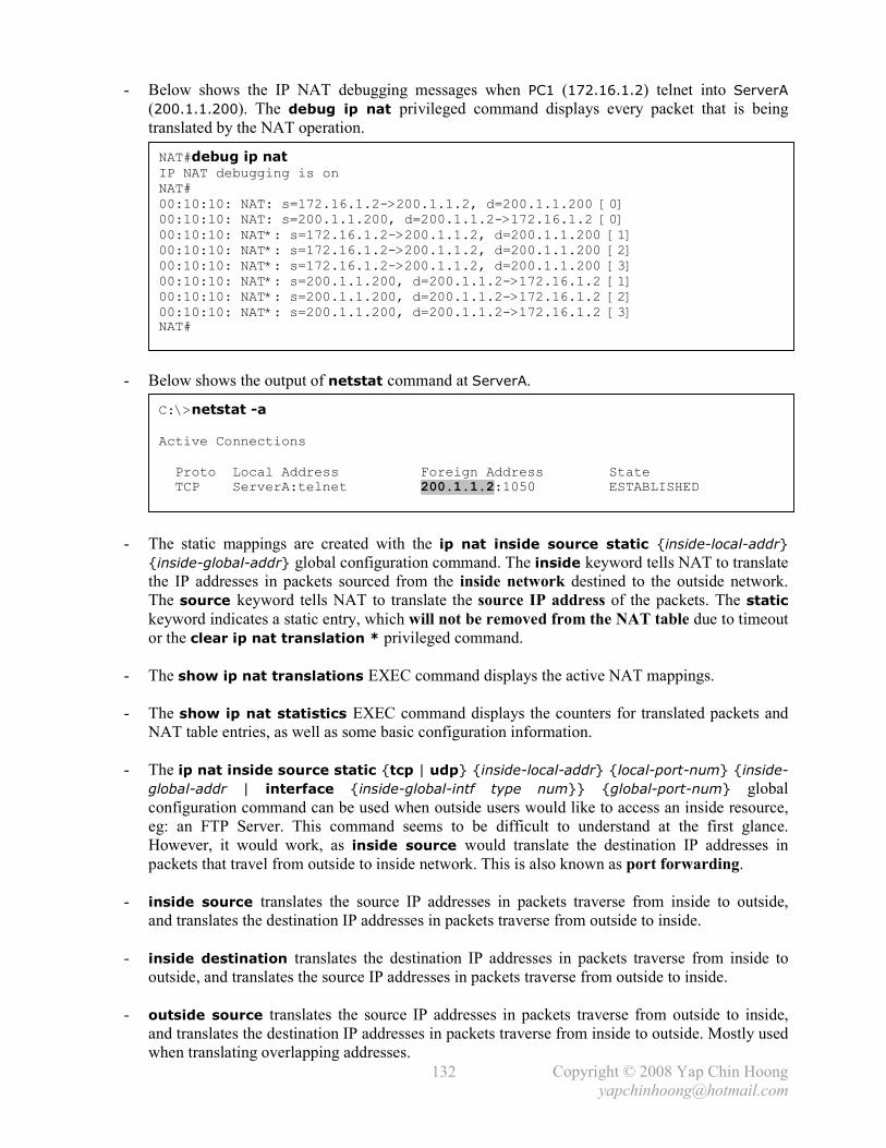
- Below shows the IP NAT debugging messages when PC1 (172.16.1.2) telnet into ServerA
(200.1.1.200). The debug ip nat privileged command displays every packet that is being
translated by the NAT operation.
- Below shows the output of netstat command at ServerA.
- The static mappings are created with the ip nat inside source static {inside-local-addr}
{inside-global-addr} global configuration command. The inside keyword tells NAT to translate
the IP addresses in packets sourced from the inside network destined to the outside network.
The source keyword tells NAT to translate the source IP address of the packets. The static
keyword indicates a static entry, which will not be removed from the NAT table due to timeout
or the clear ip nat translation * privileged command.
- The show ip nat translations EXEC command displays the active NAT mappings.
- The show ip nat statistics EXEC command displays the counters for translated packets and
NAT table entries, as well as some basic configuration information.
- The ip nat inside source static {tcp | udp} {inside-local-addr} {local-port-num} {inside-
global-addr | interface {inside-global-intf type num}} {global-port-num} global
configuration command can be used when outside users would like to access an inside resource,
eg: an FTP Server. This command seems to be difficult to understand at the first glance.
However, it would work, as inside source would translate the destination IP addresses in
packets that travel from outside to inside network. This is also known as port forwarding.
- inside source translates the source IP addresses in packets traverse from inside to outside,
and translates the destination IP addresses in packets traverse from outside to inside.
- inside destination translates the destination IP addresses in packets traverse from inside to
outside, and translates the source IP addresses in packets traverse from outside to inside.
- outside source translates the source IP addresses in packets traverse from outside to inside,
and translates the destination IP addresses in packets traverse from inside to outside. Mostly used
when translating overlapping addresses.
C:\>netstat -a
Active Connections
Proto Local Address Foreign Address State
TCP ServerA:telnet 200.1.1.2:1050 ESTABLISHED
NAT#debug ip nat IP NAT debugging is on
NAT#
00:10:10: NAT: s=172.16.1.2->200.1.1.2, d=200.1.1.200 [0]
00:10:10: NAT: s=200.1.1.200, d=200.1.1.2->172.16.1.2 [0]
00:10:10: NAT*: s=172.16.1.2->200.1.1.2, d=200.1.1.200 [1]
00:10:10: NAT*: s=172.16.1.2->200.1.1.2, d=200.1.1.200 [2]
00:10:10: NAT*: s=172.16.1.2->200.1.1.2, d=200.1.1.200 [3]
00:10:10: NAT*: s=200.1.1.200, d=200.1.1.2->172.16.1.2 [1]
00:10:10: NAT*: s=200.1.1.200, d=200.1.1.2->172.16.1.2 [2]
00:10:10: NAT*: s=200.1.1.200, d=200.1.1.2->172.16.1.2 [3] NAT#

Copyright © 2008 Yap Chin Hoong
133
Dynamic NAT Configuration
- An access list is created to include all the hosts on the inside network that are allowed to use
NAT to communicate with outside network. The ip nat pool {pool-name} {start-ip} {end-ip}
{netmask netmask | prefix-length prefix-length} global configuration command defines the
pool of inside global addresses that can be dynamically allocated for dynamic NAT operation.
- Dynamic NAT configuration on NAT:
NAT#conf t Enter configuration commands, one per line. End with CNTL/Z.
NAT(config)#no ip nat inside source static 172.16.1.2 200.1.1.2
NAT(config)#no ip nat inside source static 172.16.1.3 200.1.1.3 NAT(config)#
NAT(config)#access-list 1 permit 172.16.1.2
NAT(config)#access-list 1 permit 172.16.1.3
NAT(config)#ip nat pool pool01 200.1.1.1 200.1.1.2 netmask 255.255.255.252
NAT(config)#ip nat inside source list 1 pool pool01
NAT(config)#^Z NAT#
NAT#sh ip nat translations
NAT#sh ip nat statistics Total active translations: 0 (0 static, 0 dynamic; 0 extended)
Outside interfaces:
Ethernet0/1
Inside interfaces:
Ethernet0/0
Hits: 250 Misses: 0
Expired translations: 0
Dynamic mappings:
-- Inside Source
access-list 1 pool pool01 refcount 0
pool pool01: netmask 255.255.255.252
start 200.1.1.1 end 200.1.1.2
type generic, total addresses 2, allocated 0 (0%), misses 0
NAT# [PC1 Telnet into ServerA]
00:15:33: NAT: s=172.16.1.2->200.1.1.1, d=200.1.1.200 [0]
00:15:33: NAT: s=200.1.1.200, d=200.1.1.1->172.16.1.2 [0]
00:15:33: NAT*: s=172.16.1.2->200.1.1.1, d=200.1.1.200 [1]
00:15:33: NAT*: s=172.16.1.2->200.1.1.1, d=200.1.1.200 [2]
NAT#
NAT#sh ip nat translations Pro Inside global Inside local Outside local Outside global
--- 200.1.1.1 172.16.1.2 --- ---
NAT#sh ip nat statistics Total active translations: 1 (0 static, 1 dynamic; 0 extended)
Outside interfaces:
Ethernet0/1
Inside interfaces:
Ethernet0/0
Hits: 260 Misses: 1
Expired translations: 0
Dynamic mappings:
-- Inside Source
access-list 1 pool pool01 refcount 1
pool pool01: netmask 255.255.255.252
start 200.1.1.1 end 200.1.1.2
type generic, total addresses 2, allocated 1 (50%), misses 0 NAT#

Copyright © 2008 Yap Chin Hoong
134
- The access list indicates whether a NAT router should translate the source IP address in a packet.
Only packets with the source or destination addresses that are permitted (matched) in the access
list will be translated. Packets with the source or destination addresses that are not matched by
the access list will not be translated and the will be forwarded normally.
- With the ip nat inside source list 1 pool pool01 command configured, packets that traverse
from inside to outside with a source IP address matched by ACL 1 (172.16.1.2, 172.16.1.3)
will be translated to the an inside global address in the NAT pool pool01 (200.1.1.1, 200.1.1.2).
- The entries in the NAT table will be removed after a period of inactivity (timeout). The clear ip
nat translation * privileged command can be used to forcefully remove all dynamic NAT
entries in the NAT table. The NAT table is stored in memory and is cleared upon router reboot.
Note: Static NAT entries can only be removed with the no form of the static NAT commands in
the global configuration mode.
PAT Configuration
- PAT configuration on NAT:
Alternative configuration: NAT(config)#ip nat pool pool02 200.1.1.254 200.1.1.254 netmask 255.255.255.252
NAT(config)#ip nat inside source list 1 pool pool02 overload
NAT#conf t Enter configuration commands, one per line. End with CNTL/Z.
NAT(config)#no ip nat pool pool01 %Pool pool01 in use, cannot destroy
NAT(config)#^Z NAT#
NAT#clear ip nat translation *
NAT#conf t
NAT(config)#no ip nat pool pool01
NAT(config)#no ip nat inside source list 1 pool pool01 NAT(config)#
NAT(config)#ip nat inside source list 1 interface Ethernet0/1 overload
NAT(config)#^Z NAT#
NAT# [PC1 and PC2 Telnet into ServerA]
NAT#
NAT#sh ip nat translations Pro Inside global Inside local Outside local Outside global
tcp 200.1.1.254:1055 172.16.1.2:1055 200.1.1.200:23 200.1.1.200:23
tcp 200.1.1.254:1060 172.16.1.3:1060 200.1.1.200:23 200.1.1.200:23
NAT#
NAT#sh ip nat statistics Total active translations: 2 (0 static, 2 dynamic; 2 extended)
Outside interfaces:
Ethernet0/1
Inside interfaces:
Ethernet0/0
Hits: 285 Misses: 3
Expired translations: 0
Dynamic mappings:
-- Inside Source access-list 1 interface Ethernet0/1 refcount 2
Copyright © 2008 Yap Chin Hoong
143
Chapter 22
WAN Basics, Remote Access Technologies, and Serial PPP
- Organizations often extend their LANs to WANs, Wide Area Networks for connections to
remote sites. WANs allow the information exchange, communication and collaboration
between customers, suppliers, and among employees effectively.
- Cisco supports many types of WAN protocols. CCNA covers Serial PPP (leased lines), ISDN,
and Frame Relay.
- Below lists some common WAN terminologies:
i) Customer Premises Equipment (CPE) is the equipment that is owned by the service
subscriber and is located at the subscriber’s premise, eg: router.
ii) Demarcation Point is the spot where the responsibility of the service provider ends and
the CPE begins. The demarc is not a device or cable – it is a concept of where each party
responsibility starts and ends. When someone reported a WAN problem to the Telco and
the Telco replied that they have performed tests and are fine up to the demarc, the
problem must be caused by the CPE and is not the responsibility of the Telco.
iii) Local Loop is the connection from the demarc to the Telco switch in the closest service
provider switching office – the local CO (central office).
iv) Toll network is a collection of trunk links inside a service provider’s network.
- Below lists the common WAN connection types in the order of costing (from higher to lower):
Leased Lines Also referred to as PPP or dedicated connections. They are pre-established
connections which allow communication at any time (hence a circuit does not
need to be established before data transmission). Their cost is very high.
HDLC and PPP encapsulation protocols are frequently used on them.
They provide high bandwidth and constant data rate for data transfer.
Packet
Switching
This WAN service allows the sharing of bandwidth with other companies to
save money. It only works well for data transfer in bursty nature; hence leased
lines would be the better choice if constant data transfer is required.
Ex: X.25, Frame Relay, and ATM.
Circuit
Switching
Circuit switching operates much like a normal telephone call. The advantage
of this WAN service is low cost, where subscribers only pay for the duration of
the usage. A dedicated circuit is established, maintained, and terminated for
each communication session (hence a circuit needs to be established before
data communication). In circuit-switched networks, the resources along the
path are reserved for the duration of the communication session.
It normally provides low bandwidth for data transfer.
Ex: Modem dial-ups and ISDN.
- Data Terminal Equipment (DTE) and Data Communications Equipment (DCE):
DTEs are mostly router interfaces that connect to DCEs, eg: Channel Service Unit / Data
Service Unit (CSU/DSU), which are connects into the demarcation point (the start of the Telco
responsibility). CSUs/DSUs provide signal timing (clocking) for communication between DTEs
and DCE devices (Telco switch). CSUs/DSUs reside in the physical layer of the OSI model.
- A WAN network normally consists of 2 DTE networks connect through a DCE network.
The DCE network includes the CSU/DSU at both ends, the Telco wiring, and Telco switches.
DCE devices provide clocking to DTE interfaces, eg: router serial interfaces.

Copyright © 2008 Yap Chin Hoong
144
Figure 22-1: Basic WAN Components and Terminology
- The demarc points are not always fixed. In some cases, the CSU/DSU might owned by the Telco.
In some other cases, the Telco even owns and manages the routers at customer sites.
- Cisco routers mostly manufactured with an internal CSU/DSU, hence eliminates the connection
to an external CSU/DSU.
- Clock rate is important when defining the speed of a circuit or link. Both CSU/DSU and router
need to be configured to operate and communicate at an agreed same speed. CSUs/DSUs
provide clocking signal to routers for them to react, send and receive data at the correct rate.
Hence the CSU/DSU is considered clocking the synchronous link.
- DCE – data communication equipment. Device that provides clocking. Typically a CSU/DSU.
DTE – data terminal equipment. Device that receives clocking. Typically a router located at
subscriber premise.
- DCE cables are very useful for home labs. 2 routers, a DTE cable and a DCE cable (used to
form a back-to-back serial connection) is sufficient to simulate a point-to-point WAN link
connection without the purchase of CSU/DSU.
- DCE cables swap the transmission and reception circuits on the DTE cables.
- A back-to-back serial cable incorporates both DCE and DTE ends.
- Cisco offers a variety of WAN interface cards (WICs), eg: synchronous and asynchronous serial
WICs, ISDN BRI WICs, DSL WICs, and Analog Modem WICs.
- Below list the speeds or bit rates of common WAN link types:
Line Type Name of Signaling Type Speed / Bit Rate
64 DS0 64kbps
T1 DS1 1.544Mbps (24 DS0s + 8kbps management overhead)
T3 DS3 44.736Mbps (28 T1s + management overhead)
E1 ZM 2.048Mbps (32 DS0s)
E3 M3 34.368Mbps (16 E1s + management overhead)
J1 Y1 2.048Mbps (32 DS0s. Japan standard.)
* DSx = Digital Signal level x
* kbps = kilo bits per second
* T1 and T3 = US standards. E1 and E3 = Europe standards.
* T3 = 28 T1s. E3 = 16 E1s.
Copyright © 2008 Yap Chin Hoong
145
ATM, SONET, and SDH
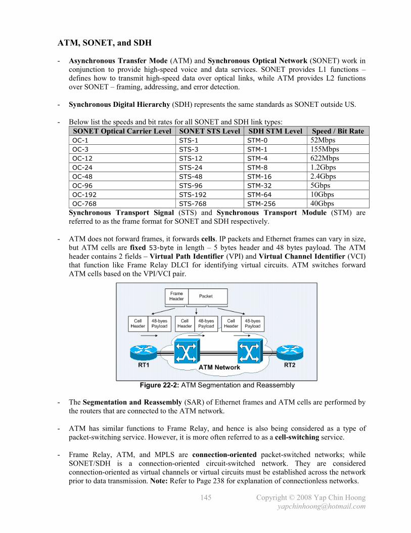
- Asynchronous Transfer Mode (ATM) and Synchronous Optical Network (SONET) work in
conjunction to provide high-speed voice and data services. SONET provides L1 functions –
defines how to transmit high-speed data over optical links, while ATM provides L2 functions
over SONET – framing, addressing, and error detection.
- Synchronous Digital Hierarchy (SDH) represents the same standards as SONET outside US.
- Below list the speeds and bit rates for all SONET and SDH link types:
SONET Optical Carrier Level SONET STS Level SDH STM Level Speed / Bit Rate
OC-1 STS-1 STM-0 52Mbps
OC-3 STS-3 STM-1 155Mbps
OC-12 STS-12 STM-4 622Mbps
OC-24 STS-24 STM-8 1.2Gbps
OC-48 STS-48 STM-16 2.4Gbps
OC-96 STS-96 STM-32 5Gbps
OC-192 STS-192 STM-64 10Gbps
OC-768 STS-768 STM-256 40Gbps
Synchronous Transport Signal (STS) and Synchronous Transport Module (STM) are
referred to as the frame format for SONET and SDH respectively.
- ATM does not forward frames, it forwards cells. IP packets and Ethernet frames can vary in size,
but ATM cells are fixed 53-byte in length – 5 bytes header and 48 bytes payload. The ATM
header contains 2 fields – Virtual Path Identifier (VPI) and Virtual Channel Identifier (VCI)
that function like Frame Relay DLCI for identifying virtual circuits. ATM switches forward
ATM cells based on the VPI/VCI pair.
Figure 22-2: ATM Segmentation and Reassembly
- The Segmentation and Reassembly (SAR) of Ethernet frames and ATM cells are performed by
the routers that are connected to the ATM network.
- ATM has similar functions to Frame Relay, and hence is also being considered as a type of
packet-switching service. However, it is more often referred to as a cell-switching service.
- Frame Relay, ATM, and MPLS are connection-oriented packet-switched networks; while
SONET/SDH is a connection-oriented circuit-switched network. They are considered
connection-oriented as virtual channels or virtual circuits must be established across the network
prior to data transmission. Note: Refer to Page 238 for explanation of connectionless networks.

Copyright © 2008 Yap Chin Hoong
146
Remote Access Technologies
- Remote access technologies are normally lower cost home-based Internet access if compared to
corporate Internet access (eg: leased lines, Frame Relay, ATM). Most remote access technologies
use the PSTN for basic physical access, eg: modems, ISDN, and DSL.
- Public Switched Telephone Network (PSTN) was built to support telephones voice traffic.
Microphones were being used to convert sound waves into analog electrical signals, and being
transported over the PSTN network to the speaker of the telephone at the other end. A circuit
must be established prior to communication.
- The core of the PSTN has evolved to use digital signals instead of analog signals, which results
in higher bandwidth and lower calling cost. Analog-to-digital (A/D) conversion is normally
performed by voice switches located at the Telco’s Central Offices (COs).
- Codec (Encoder + Decoder) is an A/D converter (ADC) that is being used for processing voices.
Figure 22-3: Analog Voice Calls over a Digital PSTN
- The original standard for the conversion of analog voice signals to digital signals is Pulse-Code
Modulation (PCM), which defines that an analog voice signal should be sampled 8000 times per
second by an A/D converter. Sampling rate is the rate at which the samples of a specific
waveform amplitude are collected within a specific period of time (eg: one second).
- The PCM standard defines the use of 256 different binary values per sample (to represent
different combination of amplitude, frequency, and phase). 256 values = 8 bits. 1 second = 8 x
8000 = 64kbps. This is the basic transmission speed that represents the necessary bandwidth for
a single PCM-encoded voice call. Due of this specification, the first digital PSTN was built on a
speed of 64kbps, and a single 64kbps channel was denoted as the Digital Signal Level 0 (DS0).
Analog Modems
- They allow 2 computers to communicate with digital signals, but without any physical changes
on the local loops and Telco’s Cos (transmit analog signals). A modem converts or encodes the
digital signals from a computer to analog signals, and sends the analog signals to the PSTN.
Another modem at the other end decodes the analog signals received from the PSTN back to
digital signals, and sends the digital signals to the computer at the other end.
- Modems are used in analog lines while CSUs/DSUs are used in digital lines.

Copyright © 2008 Yap Chin Hoong
147
- Modem � Modulation + Demodulation.
Modulation is the process of encoding a set of binary digits into an analog electrical signal.
Demodulation is the process of decoding an analog electrical signal into a set of binary digits.
- During the establishment of a modem dial-up circuit, a modem signals the tones associated with
the telephone keypad. These tones, which are generated by phones as well, are interpreted as
dual-tone multi-frequency (DTMF) tones by a CO switch. Once the circuit is established by the
Telco, the modems at both ends must agree the modem standard to use for communication.
There are many modem standards and most modems support several standards. Modems are
able to probe, negotiate, and use the best standard that is supported by the modems at both ends.
Figure 22-4: Modulation Schemes
- Modulation scheme with combination of AM and FM:
Amplitude Frequency Binary Code
Low Low 00
Low High 01
High Low 10
High High 11
- Amplitude modulation (AM) represents info by varying the amplitude of the carrier signal.
Frequency modulation (FM) represents info by varying the frequency of the carrier signal.
- Baud is a measure of the number of symbol changes or signaling events per second. A baud is a
single encoded analog energy that can represent 1 or more bits. To archive higher bit rates,
modems use certain modulation techniques to encode more than 1 bit in the analog signal.
With the AM + FM combined modulation scheme in Figure 22-4, a modem which is running at
14000 baud per second can transmit data at 28000bps.
- Most computers use PPP as the data link (L2) protocol over the L1 service provided by modems.
PPP is the good choice as modems traffic is transmitted asynchronously, while PPP support
both synchronous and asynchronous communications.
- Other reasons why PPP is being used in modem communications are:
i) PPP provides the capability to dynamically assign an IP address for a device connected
to the other end of a PPP link.
ii) PPP supports authentication (via PAP and CHAP), which is commonly being used to
authenticate dial-in users for the access to the ISP network.
- V.92 is the current modem specification defined by International Telecommunications Union
(ITU). It transmits at 56kbps (downstream) and 33kbps (upstream), which is same as V.90 but
offers a reduced handshake time (faster connection setup), increased compression throughput,
and the on-hold feature.

Copyright © 2008 Yap Chin Hoong
148
Digital Subscriber Lines (DSL)
- DSL just defines how to transmit data between a customer site and the local CO. Data do not
flow through DS0 channels inside the PSTN, but through some ISP IP networks. It does not need
to be compatible with the core of PSTN and hence is able to provide higher transmission rates.
The speed does not degrade when more users are added to the network.
Figure 22-5: DSL Connection
- The local loop connects to the DSL Access Multiplexer (DSLAM) at the local CO, which is
responsible for splitting the data and voice signals from the local loop.
- DSL allows concurrent data transmission and voice call, as it doesn’t use the voice frequencies.
Phones generate analog signals at 0–4000Hz, while DSL modems generate analog signals higher
than 4000Hz – the interference is minimal. Filters are often being used to prevent interference.
- DSL is considered an always-on Internet connection service. It does not require a circuit to be
setup before data transmission as with modems and ISDN.
- Its downstream speeds range from 1.5–8Mbps, while upstream speeds range from 64–800kbps.
- The ADSL maximum supported distance to home is 18000 feet (or ~5500 meters).
- Other DSL standards or variants include HDSL (High bit rate DSL), IDSL (ISDN DSL),
MSDSL (Multi-rate Symmetric DSL), PDSL (Powerline DSL), RADSL (Rate-Adaptive DSL),
SDSL (Symmetric DSL), SHDSL (Single-Pair High-Speed DSL), UDSL (Uni-DSL), and VDSL
(Very High Speed DSL).
- DSL routers usually include the DSL modem features, and other networking features, eg: IP
routing (allows Internet connection for multiple PCs), DHCP server, NAT, and port forwarding.

Copyright © 2008 Yap Chin Hoong
149
- DSL is a L1 service. It uses ATM as the L2 protocol for the communication between the DSL
modem (or router) and the ISP router. DSL uses PPP over ATM (PPPoA) protocol to
encapsulate PPP frames in the ATM AAL5 (ATM Adaptation Layer 5) cells. DSL transmit ATM
cells over DSL, instead of SONET. ATM cells are received and processed by the ISP router.
PPP and ATM are both L2 protocols, but they provide different functions in DSL connections.
PPP provides features such as address assignment, authentication, encryption, and compression.
- A DSL modem (or router) uses PPP over Ethernet (PPPoE) when performing bridging function
for a PC and a DSLAM when the PC connects to the DSL network using a PPPoE client.
The WAN IP address is dynamically assigned to the PC instead of the DSL router.
Cable Modems
- This remote access technology does not use a phone line for physical connectivity. It transmits
computer data in digital signals over cable TV coaxial cabling (analog). A splitter called
f-connector, is being used to split data received from drop cable to multiple cable TVs and the
cable modem in a subscriber house.
- Cable Modem Termination System (CMTS) is deployed at various concentration points or
hubs in the cable network to provide high-speed Internet access, voice, and other networking
services to home and business subscribers. The Cisco uBR (Universal Broadband Router) CMTS
Series is designed for deployments at MTUs (multi-tenant units), eg: apartments and hotels.
- The speed degrades as more subscribers are added to the network, as the bandwidth is shared
among subscribers.
- Downstream data referred to as the data going toward the home.
Upstream data referred to as the data going outward the home.
- Cable networks broadcast downstream traffic (logical bus networks). Security is a main concern.
- CATV (Community Antenna Television) standards use Multimedia Cable Network System
(MCNS) as the data link protocol for arbitration, addressing, and error detection.
- As the cables could be very long, the CSMA/CD algorithm used in Ethernet is not effective to
detect collisions in cable networks. MCNS defines some multiplexing methods – Time-Division
Multi Access (TDMA), where home users are allocated time slots per second to send upstream
data, and Frequency-Division Multiplexing (FDM) to receive downstream data.
FDM is a form of signal multiplexing where multiple baseband signals are modulated at different
frequency and bundled as a composite signal that could be transmit over a single physical circuit.
FDM was normally used in traditional analog telephone networks. Modern telephone networks
that employ digital transmission use Time-Division Multiplexing (TDM) instead of FDM.
- Multiplexing is the process of converting multiple logical signals into a single physical signal
for transmission across a physical channel.
- MCNS defines the following encoding schemes (QAM = Quadrature Amplitude Modulation):
i) QAM-64 � 6 bits per baud.
ii) QAM-256 � 8 bits per baud.
- MISC Notes: Analog modems and DSL support both symmetric and asymmetric speeds; while
ISDN, Frame Relay, and cable modems can only run across synchronous links or circuits.

Copyright © 2008 Yap Chin Hoong
150
Point-to-Point Serial Links (Leased Lines)
- The 2 most popular data link (L2) protocols that are being used over point-to-point serial links:
HDLC High-Level Data Link Control. It was derived from Synchronous Data Link Control
(SDLC) created by IBM. The HDLC specification was not intended to encapsulate
(or support) multiple network layer protocols across the same link. It does not include
a Protocol Type field and hence unable to identify the encapsulated network layer
packets. Vendors that support HDLC must define their own proprietary HDLC
headers that contain the Protocol Type field to identify the network layer protocols.
Due to this reason, HDLC implementations are proprietary – Cisco routers will not
work in connections to other vendor routers. It is the default encapsulation type used
on Cisco synchronous serial interfaces. HDLC does not support error recovery.
PPP Point-to-Point Protocol. It is an industry-standard protocol that provides an open
standard for creating point-to-point links between different vendor equipments.
It uses a standardized Protocol Type field – Network Control Protocol (NCP) field in
the header to identify the encapsulated network layer packets. It supports
authentication, multilink connections, and can operates over synchronous and
asynchronous links. PPP uses HDLC to encapsulate and transmit packets over point-
to-point links. PPP supports error recovery but is disabled by default.
Note: HDLC was developed by the International Organization for Standardization (ISO).
- HDLC does not need the arbitration feature as in Ethernet. Because on point-to-point serial links,
routers can send over the 4 wires (2 twisted-pair wires) circuit at any time, and the signal
(eventually data) will arrived at the other end of the link.
- Both HDLC and PPP frames include an address field, but it is not being used and not really
needed over point-to-point links.
- Do not confuse error detection with error recovery! Almost all data link layer protocols including
HDLC and PPP perform error detection with the FCS field in their trailers. Frames that fail the
FCS check will be noticed and discarded (error detection). Error recovery is normally being
performed by higher-layer protocols, eg: TCP.
Point-to-Point Protocol (PPP)
- When PPP was being developed, it includes many additional features that never been seen in
other WAN data link protocols up to that time.
- The PPP specification includes the following 2 subprotocols or sublayers:
i) Link Control Protocol (LCP). Responsible for establishing, configuring, testing,
maintaining, and terminating PPP connections. PPP was designed to work with several
network layer protocols, hence each PPP link has a LCP and a NCP for the corresponding
L3 protocol encapsulated and transmitted over the PPP link.
ii) Network Control Protocols (NCPs). Responsible for encapsulating network layer
protocols and assigning network layer addresses to the remote end over PPP links after
the link establishment and authentication phases. The negotiated network layer protocols
can then be transmitted across the PPP connection.
Ex: IP Control Protocol (IPCP) for IP, IPX Control Protocol (IPXCP) for IPX, and
AppleTalk Control Protocol (ATCP) for AppleTalk. A router configured for PPP
encapsulation will try to identify the network layer protocol and use the appropriate
network control protocol for the corresponding L3 protocol transmitted over the PPP link.

Copyright © 2008 Yap Chin Hoong
151
- PPP establishes a connection in 3 phases – link establishment (LCP negotiation), authentication
(optional), and network layer protocol negotiation (NCP negotiation). Both ends must agree on
the same parameters to establish a link, and authenticate each other using the authentication
protocol and option negotiated during the LCP negotiation. Authentication must be success prior
to NCP negotiation.
Figure 22-6: Point-to-Point Protocol Stack
- PPP also uses LCP to negotiate the following functions or features:
Function LCP Feature Description
Error
Detection
Link Quality Monitoring
(LQM)
Monitors link quality. PPP LCP at the
receiving end sends messages that describe the
number of correctly received packets and bytes
to the other end. The sending end calculates the
percent of loss. A link can be terminated after a
configured error rate is exceeded.
Looped Link
Detection
Magic number Endpoints send PPP LCP messages that
include a magic number, which is different for
each endpoint. A looped link is detected when
an endpoint receives an LCP message with its
own magic number instead of the magic
number of the other peer. PPP can be
configured to terminate detected looped links.
Multilink Multilink PPP Allows connections of multiple parallel
channels between 2 routers, and perform load
balancing across the multiple links.
Commonly used in ISDN links.
Authentication Password Authentication
Protocol (PAP) and
Challenge Handshake
Authen. Protocol (CHAP)
PPP initiates an authentication process to
verify the identity of the device on the other
end of the serial link. Normally used in dial-up
links (eg: modems, ISDN, and DSL).
Callback PPP Callback The calling router (client) first contacts the
remote router (server) and authenticates itself.
After the authentication process, the remote
router terminates the connection and then
reinitiates a connection to the calling router.
Normally used to minimize the long distance
dialing cost on the client side.
Compression Stacker and Predictor Compresses data at source and reproduces data
at destination. Predictor uses more memory
than Stacker; while Stacker is more CPU
intensive than Predictor.

Copyright © 2008 Yap Chin Hoong
152
- Comparisons between synchronous and asynchronous links:
Synchronous Links Asynchronous Links
Have identical frequencies. Each individual
character is encapsulated in control bits – the
Start / Stop bits, which designate the beginning
and ending of each character.
Send digital signals without timing. They
agree on the same speed, but there is no
checking or adjustment of the rates if they are
slightly different.
Send frame continuously. Send idle frames
called Receiver Ready when there is no data
transmission over the link. The purpose is to
maintain the clock synchronization.
No bits are sent during idle times. Only 1 byte
is sent per transfer.
Allow more throughputs (due to clock
synchronization).
Require less expensive hardware (do not
require clock synchronization).
Normally used for links between routers. Normally used for dial-up links (modems).
Isochronous transmission allows asynchronous data transfer over a synchronous link. It
requires constant bit rate for reliable transport.
- Below list some other common WAN data link protocols:
Protocol
Error
Recovery?
Protocol
Type Field? Other Attributes
Synchronous Data Link
Control (SDLC)
Yes No Developed by IBM. Supports
multipoint links. It assumes an
IBM SNA header after the SDLC
header. Replaced by HDLC.
High-level Data Link
Control (HDLC)
No No [1] Developed by IBM. Default on
Cisco synchronous serial links.
Qualified Logical Link
Control (QLLC)
Developed by IBM to transport
SNA traffic over X.25 networks.
Link Access Procedure
Balanced (LAPB)
Yes No [1] Mainly used in X.25 networks.
LAPB operates similar to HDLC,
but is restricted to be used only in
point-to-point links.
Link Access Procedure
– D Channel (LAPD)
No No Mainly used on ISDN D channels
for signaling in establishing and
terminating ISDN circuits.
Evolved from LAPB.
Link Access Procedure
for Frame-Mode Bearer
Services (LAPF)
No Yes Mainly used over Frame Relay
links (between a DCE and a DTE).
Similar to LAPD.
Point-to-Point Protocol
(PPP)
Yes but disabled
by default
Yes Designed for multiprotocol
interoperability.
[1] Cisco’s implementation of LAPB and HDLC includes a proprietary Protocol Type field.
- PPP and ATM can operate on synchronous and asynchronous links; while HDLC and Frame
Relay can only operate on synchronous links.
- PPP, HDLC, and LAPB are the data link layer protocols (or encapsulations) that can be used on
ISDN B channels. PPP uses HDLC to encapsulate and transmit packets over point-to-point links.

Copyright © 2008 Yap Chin Hoong
165
Chapter 25
Frame Relay Lab
Full Mesh Frame Relay Network with One IP Subnet (Multipoint Interfaces)
Figure 25-1: Full Mesh Frame Relay Network with One IP Subnet
- Frame Relay configuration on RT1, RT2, and RT3:
- Note: Watch out for split horizon issues on multipoint [sub]interfaces. Refer to Page 162 for the
discussion and the resolution of this issue.
- Frame Relay configuration can be relatively simple due to the following default IOS settings:
i) The LMI type is automatically sensed. LMI information is exchanged every 10 seconds.
If a router unable to autosense the LMI type, it would use Cisco as the LMI type.
ii) The encapsulation type (of the LAPF headers) is Cisco, instead of IETF.
iii) PVC DLCIs are learned via LMI status messages.
iv) Inverse ARP is enabled by default. It is triggered when a router received the LMI Status
Reply message that declares a VC is active. The router then uses Inverse ARP to discover
and determine the network address of a remote device by advertising itself by sending an
Inverse ARP to each active local DLCI. Inverse ARP messages are sent every 60 seconds.
Note: LMI keepalive messages and LMI status messages are different! LMI keepalive messages
are exchanged between DTE and DCE while LMI status messages are only sent in LMI Status
Reply messages which are sent from DCE to DTE.
- Frame Relay switches do not care about the encapsulation type and IP addressing. They only care
about the LMI type and the CIR.
- A router will be able to figure out the LMI type used in the Frame Relay switch without manual
configuration (with the autosense feature). Manual configuration disables the autosense feature.
RTx(config)#int s0/0
RTx(config-if)#encapsulation frame-relay
RTx(config-if)#ip add 200.1.1.{x} 255.255.255.0
RTx(config-if)#no shut
RTx(config-if)#exit
RTx(config)#router eigrp 1
RTx(config-router)#network 200.1.1.0
RTx(config-router)#network 172.16.0.0
RTx(config-router)#no auto-summary

Copyright © 2008 Yap Chin Hoong
166
- IETF Frame Relay encapsulation type must be used when there is a non-Cisco router (RT3).
Below shows the new configuration on all routers to support the following new requirements:
i) RT3 uses IETF encapsulation on all VCs on the interface.
ii) RT1 and RT2 LMI type should be ANSI, and LMI autosense should not be used.
- RT3 changes its encapsulation type on both VCs on the interface with the ietf keyword in the encapsulation command. However, RT1 and RT2 cannot change their configuration in this
way, as only one of their VCs needs to use IETF encapsulation, another one still use Cisco
encapsulation. The encapsulation type can be changed in per-VC basis (use IETF encapsulation
on VC to RT3) with the frame-relay interface-dlci {dest-dlci} ietf interface subcommand.
- Service provider’s Frame Relay switches (DCE) send LMI status messages to routers (DTE) to
update the virtual circuit status to one of the following 3 states: ACTIVE Everything is up, the connection is active, and the routers can exchange data.
INACTIVE The router’s interface is up and communicating with the local Frame Relay switch,
but the remote router’s connection to its Frame Relay switch is having problem.
DELETED No LMI message is being received from the local Frame Relay switch. It could be
a DLCI mapping problem, a line failure, or no service exists between the router
and the Frame Relay switch.
RT1 and RT2 configuration:
! interface Serial0/0 encapsulation frame-relay frame-relay lmi-type ansi frame-relay interface-dlci 103 ietf ip address 200.1.1.{x} 255.255.255.0 ! RT3 configuration:
! interface Serial0/0 encapsulation frame-relay ietf ip address 200.1.1.3 255.255.255.0 !

Copyright © 2008 Yap Chin Hoong
167
Frame Relay Address Mapping
- It is an important Frame Relay concept for mapping a L3 address with its corresponding L2
address, which is similar to the ARP process used for L3-to-L2 address mapping to figure out the
MAC address of the destination device on the same LAN before data transmission. Mapping is
only needed on multiaccess networks (point-to-point networks do not require mapping).
- Below shows the output of some Frame Relay address mapping commands on RT1:
- The show frame-relay pvc EXEC command can also be used to display the information of
Frame Relay congestion control, eg: the number of FECN and BECN packets.
- There is no DLCIs address mapping configuration on all routers. So how the routers know the
appropriate DLCI numbers to use in the Frame Relay LAPF headers when forwarding the
encapsulated packets to each other?
- The DLCIs address mapping can be built with either static configuration, or via a dynamic
process called Inverse ARP. Inverse ARP resolves an IP address from a DLCI.
- The Inverse ARP process differs from the ARP process on LANs. As soon as a VC is up, the
Inverse ARP process starts with the learning of the DLCI via LMI messages, and the router then
announces its network layer address by sending an Inverse ARP Request message over the
VC, hence allow its neighbor router to build a mapping between its L3 and L2 addresses (DLCI).
RT1#sh frame-relay pvc PVC Statistics for interface Serial0 (Frame Relay DTE) Active Inactive Deleted Static Local 2 0 0 0 Switched 0 0 0 0 Unused 0 0 0 0 DLCI = 102, DLCI USAGE = LOCAL, PVC STATUS = ACTIVE, INTERFACE = Serial0/0 input pkts 55 output pkts 52 in bytes 4907 out bytes 4845 dropped pkts 0 in FECN pkts 0 in BECN pkts 0 out FECN pkts 0 out BECN pkts 0 in DE pkts 0 out DE pkts 0 out bcast pkts 8 out bcast bytes 482 pvc create time 00:10:51, last time pvc status changed 00:09:41 DLCI = 103, DLCI USAGE = LOCAL, PVC STATUS = ACTIVE, INTERFACE = Serial0/0 input pkts 39 output pkts 18 in bytes 2564 out bytes 4845 dropped pkts 0 in FECN pkts 0 in BECN pkts 0 out FECN pkts 0 out BECN pkts 0 in DE pkts 0 out DE pkts 0 out bcast pkts 8 out bcast bytes 482 pvc create time 00:10:51, last time pvc status changed 00:05:30 RT1#
RT1#sh frame-relay map Serial0/0 (up): ip 200.1.1.2 dlci 102(0x66,0x1860), dynamic, broadcast,, status defined, active Serial0/0 (up): ip 200.1.1.3 dlci 103(0x67,0x1870), dynamic, broadcast,, status defined, active RT1#

Copyright © 2008 Yap Chin Hoong
168
Figure 25-2: Inverse ARP
- Inverse ARP messages for Figure 25-2:
Sending
Router
DLCI When the
Frame is Sent
Receiving
Router
DLCI When the
Frame is Received
Information in the
InARP Message
RT1 102 RT2 101 I am 200.1.1.1
RT1 103 RT3 101 I am 200.1.1.1
RT2 101 RT1 102 I am 200.1.1.2
RT2 103 RT3 102 I am 200.1.1.2
RT3 101 RT1 103 I am 200.1.1.3
RT3 102 RT2 103 I am 200.1.1.3
- Below shows the static mapping configuration on all routers instead of dynamic mapping with
Inverse ARP. The frame-relay map commands are required when Inverse ARP is disabled.
Frame Relay is a NBMA network, the broadcast keyword indicates that IP broadcasts can be
forwarded to this address, which is necessary for the operations of dynamic routing protocols.
- Note: Issue the no frame-relay inverse-arp interface subcommand before issuing the no
shutdown interface subcommand. This ensures that the interface does not perform InARP when
it is being enabled.
- The clear frame-relay inarp privileged command clears the dynamic Frame Relay DLCI
mappings created by Inverse ARP.
RT1(config)#int s0/0
RT1(config-if)#no frame-relay inverse-arp
RT1(config-if)#frame-relay map ip 200.1.1.2 102 broadcast
RT1(config-if)#frame-relay map ip 200.1.1.3 103 broadcast --------------------------------------------------
RT2(config)#int s0/0
RT2(config-if)#no frame-relay inverse-arp
RT2(config-if)#frame-relay map ip 200.1.1.1 101 broadcast
RT2(config-if)#frame-relay map ip 200.1.1.3 103 broadcast --------------------------------------------------
RT3(config)#int s0/0
RT3(config-if)#no frame-relay inverse-arp
RT3(config-if)#frame-relay map ip 200.1.1.1 101 broadcast
RT3(config-if)#frame-relay map ip 200.1.1.2 102 broadcast

Copyright © 2008 Yap Chin Hoong
169
Partial Mesh Frame Relay Network with One IP Subnet Per VC
(Point-to-Point Subinterfaces Configuration)
Figure 25-3: Partial Mesh Frame Relay Network with One IP Subnet Per VC
- Figure 25-3 shows a Frame Relay network with point-to-point subinterfaces configuration.
IP address is not configured on the physical interface in Frame Relay subinterfaces configuration.
- Frame Relay Point-to-Point Subinterfaces configuration on RT1:
- Frame Relay Point-to-Point Subinterfaces configuration on RT2, RT3, and RT4:
- Inverse ARP is not required for point-to-point subinterfaces; hence it is disabled by default.
RT1(config)#int s0/0
RT1(config-if)#encapsulation frame-relay
RT1(config-if)#no shut RT1(config-if)#
RT1(config-if)#int s0/0.102 point-to-point
RT1(config-subif)#ip add 200.1.1.1 255.255.255.0
RT1(config-subif)#frame-relay interface-dlci 102
RT1(config-fr-dlci)#exit
RT1(config-subif)#int s0/0.103 point-to-point
RT1(config-subif)#ip add 200.1.2.1 255.255.255.0
RT1(config-subif)#frame-relay interface-dlci 103
RT1(config-fr-dlci)#exit
RT1(config-subif)#int s0/0.104 point-to-point
RT1(config-subif)#ip add 200.1.3.1 255.255.255.0
RT1(config-subif)#frame-relay interface-dlci 104
RT1(config-fr-dlci)#exit RT1(config-subif)#
RTx(config)#int s0/0
RTx(config-if)#encapsulation frame-relay
RTx(config-if)#no shut
RTx(config-if)#int s0/0.101 point-to-point
RTx(config-subif)#ip add 200.1.{x-1}.2 255.255.255.0
RTx(config-subif)#frame-relay interface-dlci 101
RTx(config-fr-dlci)#exit RTx(config-subif)#
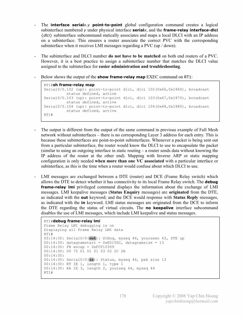
Copyright © 2008 Yap Chin Hoong
170
- The interface serialx.y point-to-point global configuration command creates a logical
subinterface numbered y under physical interface serialx, and the frame-relay interface-dlci
{dlci} subinterface subcommand statically associates and maps a local DLCI with an IP address
on a subinterface. This ensures a router associate the correct PVC with the corresponding
subinterface when it receives LMI messages regarding a PVC (up / down).
- The subinterface and DLCI number do not have to be matched on both end routers of a PVC.
However, it is a best practice to assign a subinterface number that matches the DLCI value
assigned to the subinterface for easier administration and troubleshooting.
- Below shows the output of the show frame-relay map EXEC command on RT1:
- The output is different from the output of the same command in previous example of Full Mesh
network without subinterfaces – there is no corresponding Layer 3 address for each entry. This is
because these subinterfaces are point-to-point subinterfaces. Whenever a packet is being sent out
from a particular subinterface, the router would know the DLCI to use to encapsulate the packet
(similar to using an outgoing interface in static routing – a router sends data without knowing the
IP address of the router at the other end). Mapping with Inverse ARP or static mapping
configuration is only needed when more than one VC associated with a particular interface or
subinterface, as this is the time when a router would confuse about which DLCI to use.
- LMI messages are exchanged between a DTE (router) and DCE (Frame Relay switch) which
allows the DTE to detect whether it has connectivity to its local Frame Relay switch. The debug
frame-relay lmi privileged command displays the information about the exchange of LMI
messages. LMI keepalive messages (Status Enquiry messages) are originated from the DTE,
as indicated with the out keyword; and the DCE would response with Status Reply messages,
as indicated with the in keyword. LMI status messages are originated from the DCE to inform
the DTE regarding the status of virtual circuits. The no keepalive interface subcommand
disables the use of LMI messages, which include LMI keepalive and status messages.
RT1#sh frame-relay map Serial0/0.102 (up): point-to-point dlci, dlci 102(0x66,0x1860), broadcast status defined, active Serial0/0.103 (up): point-to-point dlci, dlci 103(0x67,0x1870), broadcast status defined, active Serial0/0.104 (up): point-to-point dlci, dlci 104(0x68,0x1880), broadcast status defined, active RT1#
RT1#debug frame-relay lmi Frame Relay LMI debugging is on Displaying all Frame Relay LMI data RT1# 00:14:30: Serial0/0(out): StEnq, myseq 44, yourseen 43, DTE up 00:14:30: datagramstart = 0xE015DC, datagramsize = 13 00:14:30: FR encap = 0xFCF10309 00:14:30: 00 75 01 01 01 03 02 2C 2B 00:14:30: 00:14:30: Serial0/0(in): Status, myseq 44, pak size 13 00:14:30: RT IE 1, length 1, type 1 00:14:30: KA IE 3, length 2, yourseq 44, myseq 44 RT1# _

Copyright © 2008 Yap Chin Hoong
171
Hybrid Full and Partial Mesh Frame Relay Network
(Point-to-Point and Multipoint Subinterfaces Configuration)
Figure 25-4: Hybrid Full and Partial Mesh Frame Relay Network
- Frame Relay Point-to-Point and Multipoint Subinterfaces configuration on RT1:
- Frame Relay Point-to-Point Subinterface configuration on RT2 and RT3:
! interface Serial0/0 encapsulation frame-relay ! interface Serial0/0.102 point-to-point ip address 200.1.1.1 255.255.255.0 frame-relay interface-dlci 102 ! interface Serial0/0.103 point-to-point ip address 200.1.2.1 255.255.255.0 frame-relay interface-dlci 103 ! interface Serial0/0.888 multipoint ip address 200.1.3.1 255.255.255.0 frame-relay interface-dlci 104 frame-relay interface-dlci 105 ! interface FastEthernet1/0 ip address 172.16.1.1 255.255.255.0 !
! interface Serial0/0 encapsulation frame-relay ! interface Serial0/0.101 point-to-point ip address 200.1.{x-1}.2 255.255.255.0 frame-relay interface-dlci 101 ! interface FastEthernet1/0 ip address 172.16.x.1 255.255.255.0 !

Copyright © 2008 Yap Chin Hoong
172
- Frame Relay Multipoint Subinterface configuration on RT4:
- Frame Relay Multipoint Subinterface configuration on RT5:
- A multipoint subinterface is used when multiple VCs are associated with a subinterface.
- No mapping configuration is required, as Inverse ARP is enabled by default on multipoint
subinterfaces; while point-to-point subinterfaces never require mapping configuration.
- The output of the show frame-relay map EXEC command on RT1 includes the L3 address
mapping information on multipoint subinterfaces (learnt via Inverse ARP):
- The disadvantage of Inverse ARP is whenever the PVC data link layer is up, a DTE router needs
to learn the status and DLCIs of VCs and waits for the Inverse ARP process to occur, which can
take a considerable amount of time! Whereas with manually resolved PVCs, data transmission
is allowed as soon as the data link layer is up. Routers send InARP Request packets every 1 min.
A remote router that receives the InARP Request packet would reply with an InARP Reply
packet. Eventually both routers would have the L3-to-L2 address mapping to reach each other.
- The no interface {subif-num} global configuration command is insufficient to remove a
subinterface. The subinterface will still exist in the router’s memory. A router reboot is required.
This also applied when changing the subinterface type (reboot is required).
! interface Serial0/0 encapsulation frame-relay ! interface Serial0/0.888 multipoint ip address 200.1.3.2 255.255.255.0 frame-relay interface-dlci 101 frame-relay interface-dlci 105 ! interface FastEthernet1/0 ip address 172.16.4.1 255.255.255.0
! interface Serial0/0 encapsulation frame-relay ! interface Serial0/0.888 multipoint ip address 200.1.3.3 255.255.255.0 frame-relay interface-dlci 101 frame-relay interface-dlci 104 ! interface FastEthernet1/0 ip address 172.16.5.1 255.255.255.0
RT1#sh frame-relay map Serial0/0.102 (up): point-to-point dlci, dlci 102(0x66,0x1860), broadcast status defined, active Serial0/0.103 (up): point-to-point dlci, dlci 103(0x67,0x1870), broadcast status defined, active Serial0/0.888 (up): ip 200.1.3.2 dlci 104(0x68,0x1880), dynamic, broadcast,, status defined, active Serial0/0.888 (up): ip 200.1.3.3 dlci 105(0x69,0x1890), dynamic, broadcast,, status defined, active

Copyright © 2008 Yap Chin Hoong
207
Appendix 1
Cisco IOS Upgrade and Password Recovery Procedures
Cisco Router IOS Upgrade Procedure
Router>
Router>en
Router#conf t Enter configuration commands, one per line. End with CNTL/Z.
Router(config)#config-register 0x2101
Router(config)#^Z Router#
Router#sh ver Cisco Internetwork Operating System Software IOS (tm) 2500 Software (C2500-IS-L), Version 12.3(12), RELEASE SOFTWARE (fc3) Technical Support: http://www.cisco.com/techsupport Copyright (c) 1986-2004 by cisco Systems, Inc. Compiled Tue 30-Nov-04 02:33 by kellythw Image text-base: 0x03094EA4, data-base: 0x00001000 ROM: System Bootstrap, Version 5.2(8a), RELEASE SOFTWARE BOOTLDR: 3000 Bootstrap Software (IGS-RXBOOT), Version 10.2(8a), RELEASE SOFTWARE (fc1) Router uptime is 1 minutes System returned to ROM by power-on System image file is "flash:c2500-is-l.123-12.bin" cisco 2500 (68030) processor (revision N) with 14336K/2048K bytes of memory. Processor board ID 05534538, with hardware revision 00000000 Bridging software. X.25 software, Version 3.0.0. Basic Rate ISDN software, Version 1.1. 1 Ethernet/IEEE 802.3 interface(s) 2 Serial network interface(s) 1 ISDN Basic Rate interface(s) 32K bytes of non-volatile configuration memory. 16384K bytes of processor board System flash (Read ONLY) Configuration register is 0x2102 (will be 0x2101 at next reload)
Router#reload
System configuration has been modified. Save? [yes/no]: no Proceed with reload? [confirm] *Mar 1 00:01:33.871: %SYS-5-RELOAD: Reload requested by console. Reload Reason: Reload command. System Bootstrap, Version 5.2(8a), RELEASE SOFTWARE Copyright (c) 1986-1995 by cisco Systems 2500 processor with 14336 Kbytes of main memory Restricted Rights Legend Use, duplication, or disclosure by the Government is subject to restrictions as set forth in subparagraph (c) of the Commercial Computer Software - Restricted Rights clause at FAR sec. 52.227-19 and subparagraph (c) (1) (ii) of the Rights in Technical Data and Computer Software clause at DFARS sec. 252.227-7013.

Copyright © 2008 Yap Chin Hoong
208
cisco Systems, Inc. 170 West Tasman Drive San Jose, California 95134-1706 Cisco Internetwork Operating System Software IOS (tm) 3000 Bootstrap Software (IGS-RXBOOT), Version 10.2(8a), RELEASE SOFTWARE (fc1) Copyright (c) 1986-1995 by cisco Systems, Inc. Compiled Tue 24-Oct-95 15:46 by mkamson Image text-base: 0x01020000, data-base: 0x00001000 cisco 2500 (68030) processor (revision N) with 14332K/2048K bytes of memory. Processor board serial number 05534538 with hardware revision 00000000 X.25 software, Version 2.0, NET2, BFE and GOSIP compliant. ISDN software, Version 1.0. 1 Ethernet/IEEE 802.3 interface. 2 Serial network interfaces. 1 ISDN Basic Rate interface. 32K bytes of non-volatile configuration memory. 16384K bytes of processor board System flash (Read/Write) Press RETURN to get started! Router(boot)>
Router(boot)>en
Router(boot)#conf t Enter configuration commands, one per line. End with CNTL/Z.
Router(boot)(config)#int e0
Router(boot)(config-if)#ip add 172.16.0.1 255.255.255.0
Router(boot)(config-if)#no shut
Router(boot)(config-if)#^Z Router(boot)#
Router(boot)#ping 172.16.0.2 Type escape sequence to abort. Sending 5, 100-byte ICMP Echos to 172.16.0.2, timeout is 2 seconds: !!!!! Success rate is 100 percent (5/5), round-trip min/avg/max = 1/203/1004 ms
Router(boot)#copy tftp flash System flash directory: File Length Name/status 1 16522128 c2500-is-l.123-12.bin [16522192 bytes used, 255024 available, 16777216 total]
Address or name of remote host [255.255.255.255]? 172.16.0.2
Source file name? c2500-is-l.123-18.bin Destination file name [c2500-is-l.123-18.bin]? Accessing file 'c2500-is-l.123-18.bin' on 172.16.0.2... Loading c2500-is-l.123-18.bin from 172.16.0.2 (via Ethernet0): ! [OK] Erase flash device before writing? [confirm] Flash contains files. Are you sure you want to erase? [confirm]
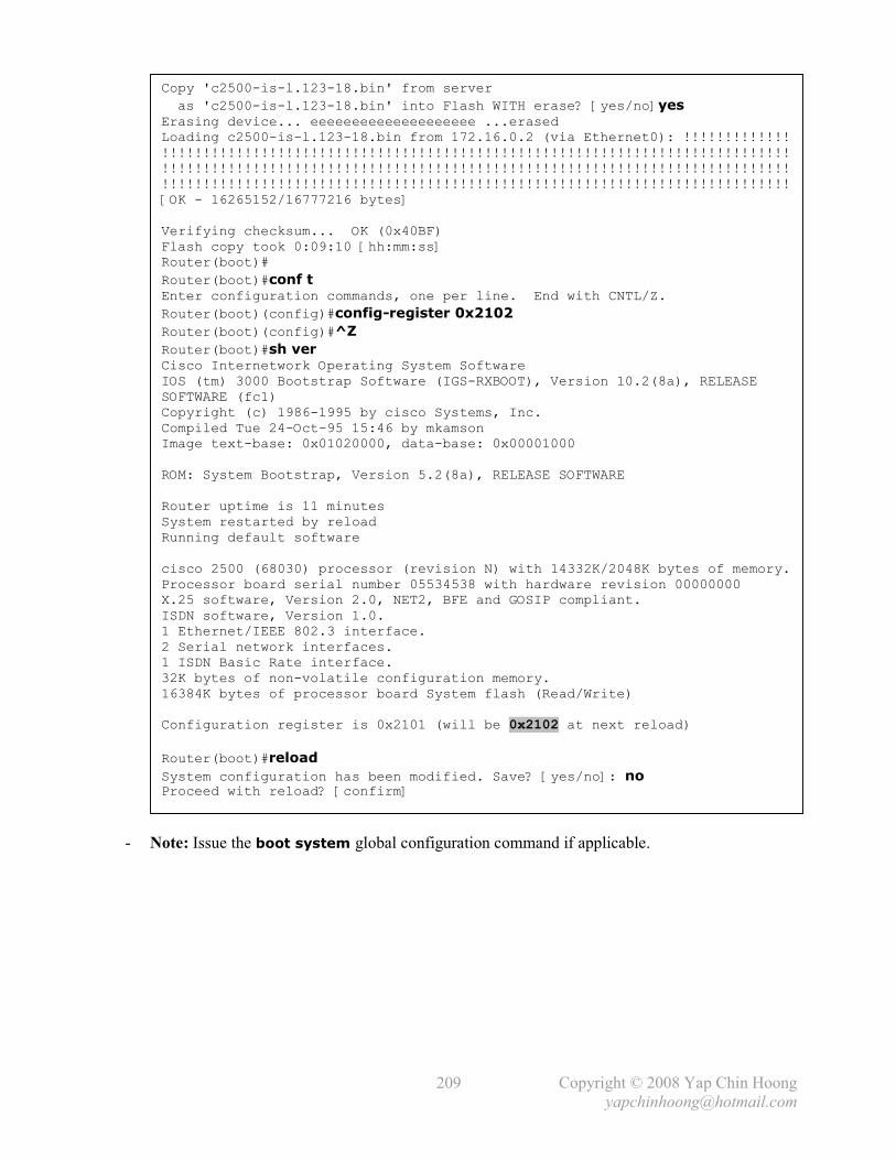
Copyright © 2008 Yap Chin Hoong
209
- Note: Issue the boot system global configuration command if applicable.
Copy 'c2500-is-l.123-18.bin' from server
as 'c2500-is-l.123-18.bin' into Flash WITH erase? [yes/no]yes Erasing device... eeeeeeeeeeeeeeeeeeee ...erased Loading c2500-is-l.123-18.bin from 172.16.0.2 (via Ethernet0): !!!!!!!!!!!!! !!!!!!!!!!!!!!!!!!!!!!!!!!!!!!!!!!!!!!!!!!!!!!!!!!!!!!!!!!!!!!!!!!!!!!!!!!!! !!!!!!!!!!!!!!!!!!!!!!!!!!!!!!!!!!!!!!!!!!!!!!!!!!!!!!!!!!!!!!!!!!!!!!!!!!!! !!!!!!!!!!!!!!!!!!!!!!!!!!!!!!!!!!!!!!!!!!!!!!!!!!!!!!!!!!!!!!!!!!!!!!!!!!!! [OK - 16265152/16777216 bytes] Verifying checksum... OK (0x40BF) Flash copy took 0:09:10 [hh:mm:ss] Router(boot)#
Router(boot)#conf t Enter configuration commands, one per line. End with CNTL/Z.
Router(boot)(config)#config-register 0x2102
Router(boot)(config)#^Z
Router(boot)#sh ver Cisco Internetwork Operating System Software IOS (tm) 3000 Bootstrap Software (IGS-RXBOOT), Version 10.2(8a), RELEASE SOFTWARE (fc1) Copyright (c) 1986-1995 by cisco Systems, Inc. Compiled Tue 24-Oct-95 15:46 by mkamson Image text-base: 0x01020000, data-base: 0x00001000 ROM: System Bootstrap, Version 5.2(8a), RELEASE SOFTWARE Router uptime is 11 minutes System restarted by reload Running default software cisco 2500 (68030) processor (revision N) with 14332K/2048K bytes of memory. Processor board serial number 05534538 with hardware revision 00000000 X.25 software, Version 2.0, NET2, BFE and GOSIP compliant. ISDN software, Version 1.0. 1 Ethernet/IEEE 802.3 interface. 2 Serial network interfaces. 1 ISDN Basic Rate interface. 32K bytes of non-volatile configuration memory. 16384K bytes of processor board System flash (Read/Write) Configuration register is 0x2101 (will be 0x2102 at next reload)
Router(boot)#reload
System configuration has been modified. Save? [yes/no]: no Proceed with reload? [confirm]

Copyright © 2008 Yap Chin Hoong
210
Catalyst Switch IOS Upgrade Procedure (Cisco IOS Release 12.0)
Switch>
Switch>en
Switch#conf t Enter configuration commands, one per line. End with CNTL/Z.
Switch(config)#int vlan 1
Switch(config-if)#ip add 172.16.0.1 255.255.255.0
Switch(config-if)#no shut
Switch(config-if)#^Z Switch#
Switch#ping 172.16.0.2 Type escape sequence to abort. Sending 5, 100-byte ICMP Echos to 172.16.0.2, timeout is 2 seconds: !!!!! Success rate is 100 percent (5/5), round-trip min/avg/max = 1/202/1002 ms Switch#
Switch#dir Directory of flash:/ 2 -rwx 1809119 Aug 10 2004 23:04:33 c2900xl-c3h2s-mz.120-5.WC10.bin 3 -rwx 105970 Jul 18 2000 01:26:29 c2900XL-diag-mz-120.5.2-XU 4 drwx 704 Aug 10 2004 23:05:26 html 18 -rwx 994 Mar 01 1993 00:00:46 config.text 20 -rwx 329 Mar 01 1993 00:00:50 env_vars 5 -rwx 8192 Aug 10 2004 23:04:34 e2rb.bin 17 -rwx 109 Aug 10 2004 23:05:28 info 3612672 bytes total (571392 bytes free) Switch#
Switch#del flash:c2900xl-c3h2s-mz.120-5.WC10.bin Delete filename [c2900xl-c3h2s-mz.120-5.WC10.bin]? Delete flash:c2900xl-c3h2s-mz.120-5.WC10.bin? [confirm]
Switch#del flash:html/*.* Delete filename [html/*.*]? Delete flash:html/homepage.htm? [confirm] --- output omitted ---
Switch#rmdir flash:html Rmdir filename [html]? Delete flash:html? [confirm] Removed dir flash:html
Switch#dir Directory of flash:/ 3 -rwx 105970 Jul 18 2000 01:26:29 c2900XL-diag-mz-120.5.2-XU 18 -rwx 994 Mar 01 1993 00:00:46 config.text 20 -rwx 329 Mar 01 1993 00:00:50 env_vars 5 -rwx 8192 Aug 10 2004 23:04:34 e2rb.bin 17 -rwx 109 Aug 10 2004 23:05:28 info 3612672 bytes total (3495424 bytes free) Switch#
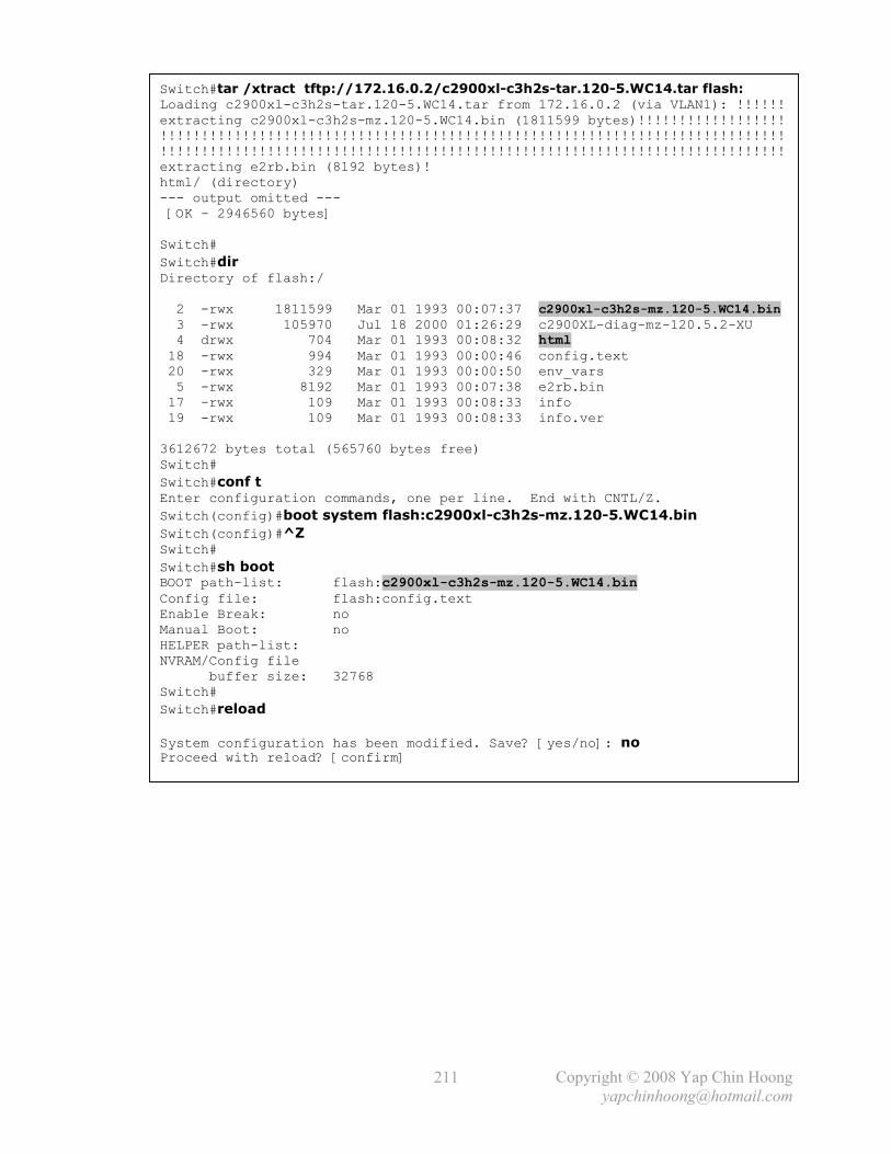
Copyright © 2008 Yap Chin Hoong
211
Switch#tar /xtract tftp://172.16.0.2/c2900xl-c3h2s-tar.120-5.WC14.tar flash: Loading c2900xl-c3h2s-tar.120-5.WC14.tar from 172.16.0.2 (via VLAN1): !!!!!! extracting c2900xl-c3h2s-mz.120-5.WC14.bin (1811599 bytes)!!!!!!!!!!!!!!!!!! !!!!!!!!!!!!!!!!!!!!!!!!!!!!!!!!!!!!!!!!!!!!!!!!!!!!!!!!!!!!!!!!!!!!!!!!!!!! !!!!!!!!!!!!!!!!!!!!!!!!!!!!!!!!!!!!!!!!!!!!!!!!!!!!!!!!!!!!!!!!!!!!!!!!!!!! extracting e2rb.bin (8192 bytes)! html/ (directory) --- output omitted --- [OK - 2946560 bytes] Switch#
Switch#dir Directory of flash:/ 2 -rwx 1811599 Mar 01 1993 00:07:37 c2900xl-c3h2s-mz.120-5.WC14.bin 3 -rwx 105970 Jul 18 2000 01:26:29 c2900XL-diag-mz-120.5.2-XU 4 drwx 704 Mar 01 1993 00:08:32 html 18 -rwx 994 Mar 01 1993 00:00:46 config.text 20 -rwx 329 Mar 01 1993 00:00:50 env_vars 5 -rwx 8192 Mar 01 1993 00:07:38 e2rb.bin 17 -rwx 109 Mar 01 1993 00:08:33 info 19 -rwx 109 Mar 01 1993 00:08:33 info.ver 3612672 bytes total (565760 bytes free) Switch#
Switch#conf t Enter configuration commands, one per line. End with CNTL/Z.
Switch(config)#boot system flash:c2900xl-c3h2s-mz.120-5.WC14.bin
Switch(config)#^Z Switch#
Switch#sh boot BOOT path-list: flash:c2900xl-c3h2s-mz.120-5.WC14.bin Config file: flash:config.text Enable Break: no Manual Boot: no HELPER path-list: NVRAM/Config file buffer size: 32768 Switch#
Switch#reload
System configuration has been modified. Save? [yes/no]: no Proceed with reload? [confirm]

Copyright © 2008 Yap Chin Hoong
212
Catalyst Switch IOS Upgrade Procedure (Cisco IOS Release 12.1 and later)
Switch>
Switch>en
Switch#conf t Enter configuration commands, one per line. End with CNTL/Z.
Switch(config)#int vlan 1
Switch(config-if)#ip add 172.16.0.1 255.255.255.0
Switch(config-if)#no shut
Switch(config-if)#^Z Switch#
Switch#ping 172.16.0.2 Type escape sequence to abort. Sending 5, 100-byte ICMP Echos to 172.16.0.2, timeout is 2 seconds: !!!!! Success rate is 100 percent (5/5), round-trip min/avg/max = 1/200/1000 ms Switch#
Switch#dir Directory of flash:/ 2 -rwx 2126 Mar 1 1993 00:01:15 +00:00 config.text 4 -rwx 24 Mar 1 1993 00:01:15 +00:00 private-config.text 7 drwx 192 Mar 1 1993 00:13:41 +00:00 c3550-i5k91l2q3-mz.122-25.SE 8 drwx 192 Mar 1 1993 00:04:27 +00:00 c3550-i9q3l2-mz.121-19.EA1c 420 -rwx 350 Mar 1 1993 00:13:41 +00:00 system_env_vars 419 -rwx 0 Mar 1 1993 00:13:41 +00:00 env_vars 15998976 bytes total (1409024 bytes free) Switch#
Switch#delete /force /recursive flash:c3550-i5k91l2q3-mz.122-25.SE Delete filename [c3550-i5k91l2q3-mz.122-25.SE]? Switch#
Switch#archive download-sw tftp://172.16.0.2/c3550-ipservicesk9-tar.122-
25.SEE.tar Loading c3550-ipservicesk9-tar.122-25.SEE.tar from 172.16.0.2 (via Vlan1): ! !!!!!!!!!!!!!!!!!!!!!!!!!!!!!!!!!!!!!!!!!!!!!!!!!!!!!!!!!!!!!!!!!!!!!!!!!!!! !!!!!!!!!!!!!!!!!!!!!!!!!!!!!!!!!!!!!!!!!!!!!!!!!!!!!!!!!!!!!!!!!!!!!!!!!!!! !!!!!!!!!!!!!!!!!!!!!!!!!!!!!!!!!!!!!!!!!!!!!!!!!!!!!!!!!!!!!!!!!!!!!!!!!!!! [OK - 8878080 bytes] examining image... extracting info (287 bytes) Image info: Version Suffix: ipservicesk9-122-25.SEE Image Name: c3550-ipservicesk9-mz.122-25.SEE.bin Version Directory: c3550-ipservicesk9-mz.122-25.SEE Ios Image Size: 7137792 Total Image Size: 8878592 Image Feature: IP|LAYER_3|PLUS|SSH|3DES|MIN_DRAM_MEG=64
Image Family: C3550

Copyright © 2008 Yap Chin Hoong
213
Extracting files... extracting info (287 bytes) extracting c3550-ipservicesk9-mz.122-25.SEE/c3550-ipservicesk9-mz.122-25.SEE.bin (7131928 bytes) c3550-ipservicesk9-mz.122-25.SEE/html/ (directory) extracting c3550-ipservicesk9-mz.122-25.SEE/html/layers.js (1616 bytes) --- output omitted --- extracting info.ver (287 bytes) New software image installed in flash:c3550-ipservicesk9-mz.122-25.SEE Configuring system to use new image...done. Switch#
Switch#sh boot BOOT path-list: flash:c3550-ipservicesk9-mz.122-25.SEE/c3550-ipservicesk9-mz.122-25.SEE.bin Config file: flash:/config.text Private Config file: flash:/private-config.text Enable Break: no Manual Boot: no HELPER path-list: NVRAM/Config file buffer size: 393216 Switch#
Switch#reload
System configuration has been modified. Save? [yes/no]: no Proceed with reload? [confirm]

Copyright © 2008 Yap Chin Hoong
214
Cisco Router Password Recovery Procedure
- Power on the router, and then send a break sequence (Ctrl-Break) to enter ROMmon.
[1] – Change the configuration register to ignore the contents of NVRAM. Use the confreg
command instead on Cisco 2600 Series and later.
System Bootstrap, Version 5.2(11a), RELEASE SOFTWARE Copyright (c) 1986-1995 by cisco Systems 4000 processor with 16384 Kbytes of main memory Abort at 0x10fb602 (PC)
>o Configuration register = 0xffff2102 at last boot Bit# Configuration register option settings: 15 Diagnostic mode disabled 14 IP broadcasts do not have network numbers 13 Boot default ROM software if network boot fails 12-11 Console speed is 9600 baud 10 IP broadcasts with ones 08 Break disabled 07 OEM disabled 06 Ignore configuration disabled 03-00 Boot file is cisco2-4000 (or 'boot system' command) >
>o/r 0x2142 [1]
>i System Bootstrap, Version 5.2(11a), RELEASE SOFTWARE Copyright (c) 1986-1995 by cisco Systems 4000 processor with 16384 Kbytes of main memory F3: 9248+6029511+165008 at 0x12000 Self decompressing the image : ############################################################################ ############################################################################ ########################################################## [OK] Restricted Rights Legend Use, duplication, or disclosure by the Government is subject to restrictions as set forth in subparagraph (c) of the Commercial Computer Software - Restricted Rights clause at FAR sec. 52.227-19 and subparagraph (c) (1) (ii) of the Rights in Technical Data and Computer Software clause at DFARS sec. 252.227-7013. cisco Systems, Inc. 170 West Tasman Drive San Jose, California 95134-1706 Cisco Internetwork Operating System Software IOS (tm) 4000 Software (C4000-JS-M), Version 12.1(27b), RELEASE SOFTWARE (fc1) Copyright (c) 1986-2005 by cisco Systems, Inc. Compiled Tue 16-Aug-05 16:53 by pwade Image text-base: 0x00012000, data-base: 0x00C19718

Copyright © 2008 Yap Chin Hoong
215
cisco 4000 (68030) processor (revision 0xA0) with 16384K/4096K bytes of memory. Processor board ID 5079453 G.703/E1 software, Version 1.0. Bridging software. X.25 software, Version 3.0.0. SuperLAT software (copyright 1990 by Meridian Technology Corp). TN3270 Emulation software. 2 Ethernet/IEEE 802.3 interface(s) 2 Serial network interface(s) 128K bytes of non-volatile configuration memory. 8192K bytes of processor board System flash (Read/Write) --- System Configuration Dialog ---
Would you like to enter the initial configuration dialog? [yes/no]: no Press RETURN to get started! Router>
Router>en
Router#copy startup-config running-config Router#
Router#conf t Enter configuration commands, one per line. End with CNTL/Z.
Router(config)#no enable secret
Router(config)#enable secret cisco Router(config)#
Router(config)#config-register 0x2102
Router(config)#^Z Router#
Router#sh ver Cisco Internetwork Operating System Software IOS (tm) 4000 Software (C4000-JS-M), Version 12.1(27b), RELEASE SOFTWARE (fc1) Copyright (c) 1986-2005 by cisco Systems, Inc. Compiled Tue 16-Aug-05 16:53 by pwade Image text-base: 0x00012000, data-base: 0x00C19718 --- output omitted --- Configuration register is 0x2142 (will be 0x2102 at next reload)
Router#
Router#copy running-config startup-config Building configuration... [OK] Router#

Copyright © 2008 Yap Chin Hoong
216
Catalyst Switch Password Recovery Procedure
- Hold down the Mode button located on the left side of the front panel while powering the switch.
Release the Mode button after the Port 1 LED goes out.
C2900XL Boot Loader (C2900-HBOOT-M) Version 12.0(5.2)XU, MAINTENANCE INTERIM SOFTWARE Compiled Mon 17-Jul-00 18:19 by ayounes starting... Base ethernet MAC Address: 00:04:27:c1:d3:c0 Xmodem file system is available. The system has been interrupted prior to initializing the flash filesystem. The following commands will initialize the flash filesystem, and finish loading the operating system software: flash_init load_helper boot
switch: flash_init Initializing Flash... flashfs[0]: 18 files, 2 directories flashfs[0]: 0 orphaned files, 0 orphaned directories flashfs[0]: Total bytes: 3612672 flashfs[0]: Bytes used: 3046912 flashfs[0]: Bytes available: 565760 flashfs[0]: flashfs fsck took 6 seconds. ...done Initializing Flash. Boot Sector Filesystem (bs:) installed, fsid: 3 Parameter Block Filesystem (pb:) installed, fsid: 4
switch: load_helper
switch: rename flash:config.text flash:config.old
switch: boot Loading "flash:c2900xl-c3h2s-mz.120-5.WC14.bin"...########################## ############################################################################ ############################################################################ File "flash:c2900xl-c3h2s-mz.120-5.WC14.bin" uncompressed and installed, entry point: 0x3000 executing... Restricted Rights Legend Use, duplication, or disclosure by the Government is subject to restrictions as set forth in subparagraph (c) of the Commercial Computer Software - Restricted Rights clause at FAR sec. 52.227-19 and subparagraph (c) (1) (ii) of the Rights in Technical Data and Computer Software clause at DFARS sec. 252.227-7013. cisco Systems, Inc. 170 West Tasman Drive San Jose, California 95134-1706
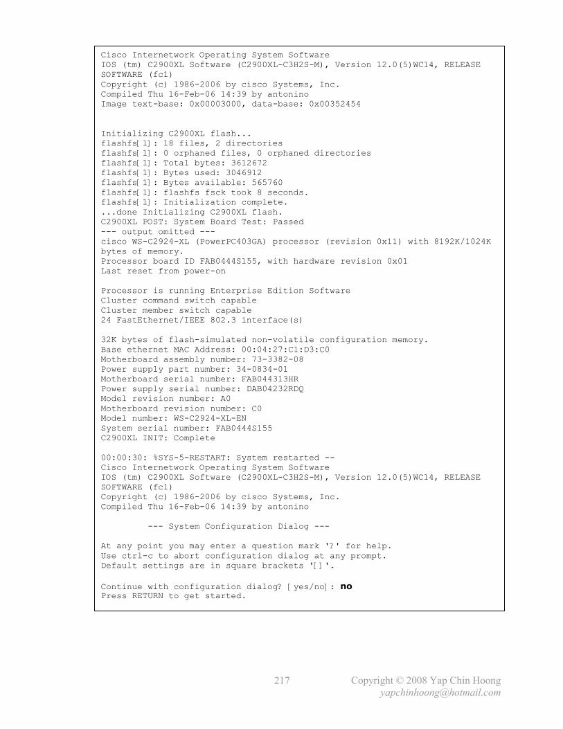
Copyright © 2008 Yap Chin Hoong
217
Cisco Internetwork Operating System Software IOS (tm) C2900XL Software (C2900XL-C3H2S-M), Version 12.0(5)WC14, RELEASE SOFTWARE (fc1) Copyright (c) 1986-2006 by cisco Systems, Inc. Compiled Thu 16-Feb-06 14:39 by antonino Image text-base: 0x00003000, data-base: 0x00352454 Initializing C2900XL flash... flashfs[1]: 18 files, 2 directories flashfs[1]: 0 orphaned files, 0 orphaned directories flashfs[1]: Total bytes: 3612672 flashfs[1]: Bytes used: 3046912 flashfs[1]: Bytes available: 565760 flashfs[1]: flashfs fsck took 8 seconds. flashfs[1]: Initialization complete. ...done Initializing C2900XL flash. C2900XL POST: System Board Test: Passed --- output omitted --- cisco WS-C2924-XL (PowerPC403GA) processor (revision 0x11) with 8192K/1024K bytes of memory. Processor board ID FAB0444S155, with hardware revision 0x01 Last reset from power-on Processor is running Enterprise Edition Software Cluster command switch capable Cluster member switch capable 24 FastEthernet/IEEE 802.3 interface(s) 32K bytes of flash-simulated non-volatile configuration memory. Base ethernet MAC Address: 00:04:27:C1:D3:C0 Motherboard assembly number: 73-3382-08 Power supply part number: 34-0834-01 Motherboard serial number: FAB044313HR Power supply serial number: DAB04232RDQ Model revision number: A0 Motherboard revision number: C0 Model number: WS-C2924-XL-EN System serial number: FAB0444S155 C2900XL INIT: Complete 00:00:30: %SYS-5-RESTART: System restarted -- Cisco Internetwork Operating System Software IOS (tm) C2900XL Software (C2900XL-C3H2S-M), Version 12.0(5)WC14, RELEASE SOFTWARE (fc1) Copyright (c) 1986-2006 by cisco Systems, Inc. Compiled Thu 16-Feb-06 14:39 by antonino --- System Configuration Dialog --- At any point you may enter a question mark '?' for help. Use ctrl-c to abort configuration dialog at any prompt. Default settings are in square brackets '[]'.
Continue with configuration dialog? [yes/no]: no Press RETURN to get started.

Copyright © 2008 Yap Chin Hoong
218
Switch>
Switch>en
Switch#rename config.old config.text Destination filename [config.text]? Switch#
Switch#copy config.text running-config Destination filename [running-config]? 994 bytes copied in 2.301 secs (497 bytes/sec) Switch#
Switch#conf t Enter configuration commands, one per line. End with CNTL/Z.
Switch(config)#no enable secret
Switch(config)#enable secret cisco
Switch(config)#^Z Switch#
Switch#copy running-config startup-config Building configuration... [OK] Switch#

Copyright © 2008 Yap Chin Hoong
235
Appendix 6
CCNA Extra Knowledge
Topic Page
MISC Basic Networking Notes 236
The LLC – Logical Link Control (IEEE 802.2) 236
Late Collision 236
Duplex and Simple Communications 237
Manually Configured (Static) MAC Address 237
MISC Data Link Layer Notes 238
MISC Physical Layer Notes 239
Multiplexing Methods 241
Ethernet Autonegotiation and Duplex Mismatch 242
ISO-TP: OSI Transport Layer Protocols 243
The TCP Connection States 244
HTTP and TCP TIME_WAIT State 247
Dissecting TCP and IP Header Fields 247
TCP Selective Acknowledgment (SACK) and Fast Retransmission 250
Dive into Proxy ARP 251
Local Proxy ARP 251
Determining Cisco Router Memory Size 253
The Myth of the Running Configuration file 253
Spanning Tree Protocol Port ID 254
Router-on-a-Stick VLAN Trunking Encapsulation and IP Address Configuration 254
switchport trunk encapsulation and switchport mode trunk Configuration 255
The Problem of Router-on-a-Stick Configuration on Ethernet Interface 256
Switching Technologies 257
Dissecting Subnet Zero 257
Default Route (Gateway of Last Resort) Configurations 259
The passive-interface Router Subcommand 259
The permanent keyword in the Static Route Configuration 260
RIPv1 and VLSM 262
Fun with NATs and ACLs (Firewalls) 263
NAT with Virtual Interface 266
NAT Attack Session – ip nat inside source and ip nat outside source 267
Complex ACL 269
The Access Control List established Keyword 270
The Access Control List fragments Keyword 271
Switch Port Access Control Lists 272
Advanced Access Control List Configurations 273
Optional PPP Commands 278
Unidirectional PPP PAP Authentication 278
Unidirectional PPP CHAP Authentication 283
Frame Relay DLCIs 285
IEEE 802.11 Standards and Specifications 286
IEEE 802.11 Frame Types 287
IEEE 802.11 Types and Subtypes 292
IEEE 802.1X Port-Based Authentication 293
VPN and IPsec Basics 295
Troubleshooting ISDN 303
Copyright © 2008 Yap Chin Hoong
236
MISC Basic Networking Notes
- The most common network user applications on today’s networks are email, web browsers,
instant messaging, collaboration, and databases.
- Below are the 3 categories of network applications:
i) Batch applications are started by a human complete with no other interaction, eg: FTP
and TFTP.
ii) Interactive applications include database updates and queries. A person requests data
from the server and waits for a reply. Response time depends more on the server than the
network.
iii) Real-time applications include VoIP and video. Network bandwidth is critical as these
applications are time critical. Quality of Service (QoS) and sufficient network bandwidth
are mandatory for these applications.
The LLC – Logical Link Control (IEEE 802.2)
- LLC was originated from the High-Level Data Link Control (HDLC) and uses a subset of the
HDLC specification. It is the upper data link sublayer that provides an interface for upper layers
to deal with any type of MAC lower sublayer, eg: 802.3 Ethernet and 802.5 Token Ring in order
to achieve physical media independence. It is used for managing the data link communication,
defining Service Access Points (SAPs) to identify and encapsulate network layer protocols.
Note: LLC is the same for various physical media, eg: Ethernet, Token Ring, and WLAN.
- LLC defines 3 types of operations (or services) for data communication:
LLC Type 1 Connectionless and unreliable. Allows network layer protocols to run on it.
Generally used by network layer protocols that using a transport layer.
LLC Type 2 Connection-oriented and reliable. Allows the LLC sublayer to provide
connection establishment, data acknowledgement, error recovery, and flow
control (windowing or sliding window). A retransmission timer is started when
an endpoint sends frames to its peer. The frames will be retransmitted if an
acknowledgment is not received within the timeout interval.
Generally used in LAN environments where network and transport layer
protocols are not involved.
LLC Type 3 Connectionless and reliable.
- Connection-oriented LLC (LLC2) uses a 2-byte Control field (in the 802.2 LLC header).
Late Collision
- Late collision is a type of collisions found in the CSMA/CD environment where a collision error
is detected after the first 64 bytes of the frame have been sent. It occurs when 2 end systems
encounter a collision upon frame transmission even they have performed collision detection.
This condition can occur when the network is so large that the frame propagation from one end
to another takes longer than the time used to perform collision detection.
- Late collisions are not retransmitted by the NIC (Layer 2). They are left for the upper layers
(eg: TCP) to detect and recover the loss of data.
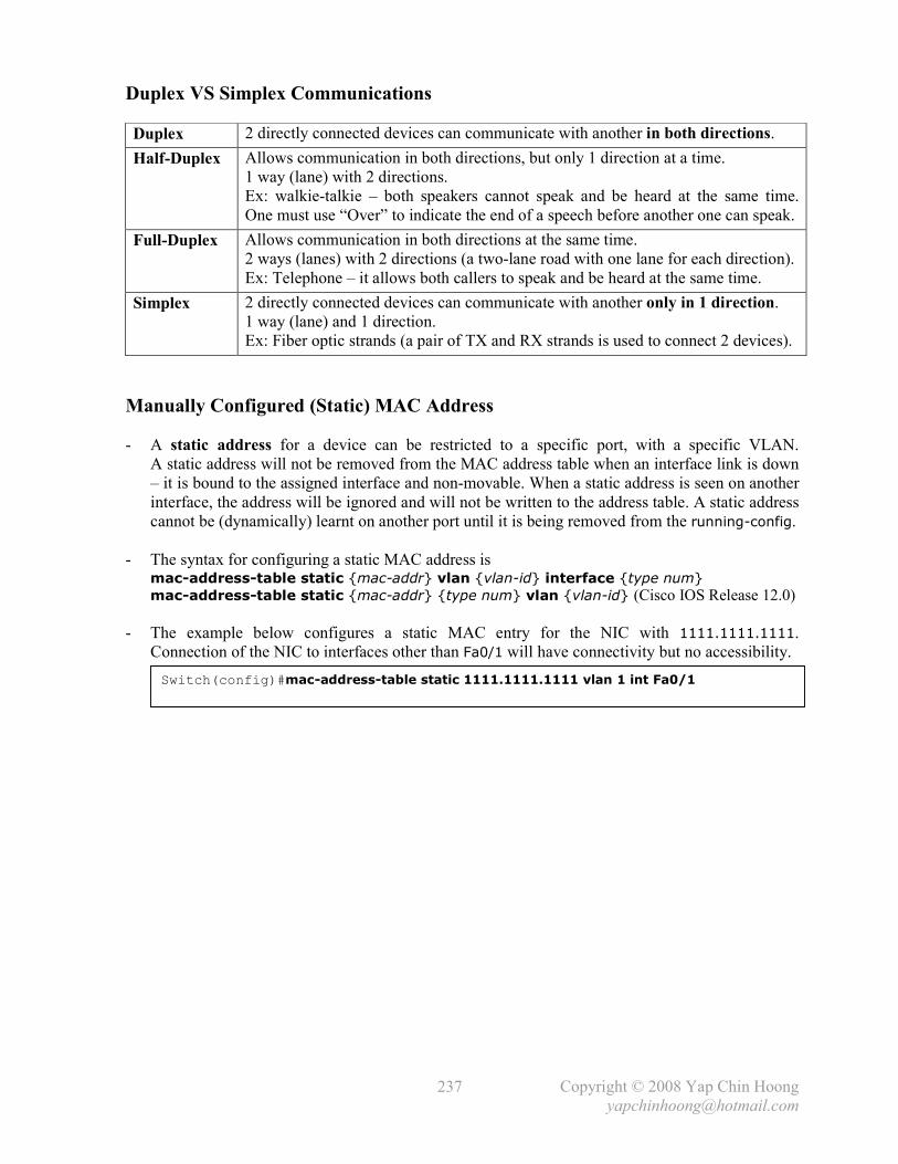
Copyright © 2008 Yap Chin Hoong
237
Duplex VS Simplex Communications
Duplex 2 directly connected devices can communicate with another in both directions.
Half-Duplex Allows communication in both directions, but only 1 direction at a time.
1 way (lane) with 2 directions.
Ex: walkie-talkie – both speakers cannot speak and be heard at the same time.
One must use “Over” to indicate the end of a speech before another one can speak.
Full-Duplex Allows communication in both directions at the same time.
2 ways (lanes) with 2 directions (a two-lane road with one lane for each direction).
Ex: Telephone – it allows both callers to speak and be heard at the same time.
Simplex 2 directly connected devices can communicate with another only in 1 direction.
1 way (lane) and 1 direction.
Ex: Fiber optic strands (a pair of TX and RX strands is used to connect 2 devices).
Manually Configured (Static) MAC Address
- A static address for a device can be restricted to a specific port, with a specific VLAN.
A static address will not be removed from the MAC address table when an interface link is down
– it is bound to the assigned interface and non-movable. When a static address is seen on another
interface, the address will be ignored and will not be written to the address table. A static address
cannot be (dynamically) learnt on another port until it is being removed from the running-config.
- The syntax for configuring a static MAC address is mac-address-table static {mac-addr} vlan {vlan-id} interface {type num}
mac-address-table static {mac-addr} {type num} vlan {vlan-id} (Cisco IOS Release 12.0)
- The example below configures a static MAC entry for the NIC with 1111.1111.1111.
Connection of the NIC to interfaces other than Fa0/1 will have connectivity but no accessibility.
Switch(config)#mac-address-table static 1111.1111.1111 vlan 1 int Fa0/1

Copyright © 2008 Yap Chin Hoong
238
MISC Data Link Layer Notes
- Ethernet is an example of connectionless networks, which means that the destination end
systems are not contacted prior to communication, nor is there any mechanism for the sender to
know whether a frame has reached its intended destination.
- Every time a transparent bridge learns a MAC address, it would timestamp the entry.
When the bridge sees a frame from this MAC address, it refreshes the timestamp. If the bridge
does not hear from this source for a specific amount of time (aging timer), the bridge deletes the
entry from its bridging table. The default MAC address table aging timer is 5 minutes.
- Content-Addressable Memory (CAM) is a special type of computer memory that implements
the lookup-table function in a single clock cycle (single operation) using dedicated comparison
circuitry. CAMs are hardware-based search engines that are much faster than algorithmic
approaches for search-intensive applications. CAMs are especially popular in network devices,
which require high-speed table lookup for packet switching and forwarding.
- The default ARP table aging time is 4 hours (14400 seconds); while the default MAC address
table aging time is 5 minutes (300 seconds). Aging time is the period that an entry is being kept.
- The arp timeout {seconds} interface subcommand and mac-address-table aging-time
{seconds} global configuration command modify the ARP table aging timer and MAC address
table aging timer respectively.
- A balanced line is a transmission line that consists of 2 connectors of the same type which there
is no master-slave relationship – the DTE and DCE are treated as equals. Each station may
initialize, supervise, recovery from errors, and send frames at any time.
- A balun can be used to convert balanced signal to unbalanced signal.
- Alignment error is an error that occurs in Ethernet networks, where a received frame has extra
bits – a number that is not divisible by 8. Alignment errors are generally caused by collisions and
eventually frame damage.
- Bit-oriented protocols are data link layer protocols that transmit frames regardless of the frame
content. Byte-oriented protocols use a specific character from the user character set to mark the
boundaries of frames. As compared with byte-oriented protocols, bit-oriented protocols are more
efficient and support full-duplex operation. As a result, byte-oriented protocols have been
superceded or replaced by bit-oriented protocols.
- Broadcasts and IP networks are not limited to VLANs, even though it is very tempting to think so.
If 2 switches are connected with a crossover cable, with one configured with VLAN 10 on all
ports, and another configured with VLAN 20 on all ports; hosts that connected to the switches
are able to communicate as they as on the same IP network!

Copyright © 2008 Yap Chin Hoong
239
MISC Physical Layer Notes
- The maximum point-to-point transmitting distance for a full-duplex mode 100BaseTX/FX
multimode fiber converter is 2KM; under half-duplex mode, this is limited to 412m.
- The maximum point-to-point transmitting distance for a full-duplex mode 100BaseTX/FX
single-mode fiber converter is 120KM. It is not recommended for a 100BaseTX/FX single-mode
fiber converter to run under half-duplex mode with single-mode fiber.
- To fully utilize the advantage of long-distance transmission with fiber optics, the 100BaseTX/FX
converters should be deployed together with switches instead of hubs, as switches support full-
duplex mode, which allows point-to-point connection up to 2KM for multimode fiber and up to
120KM for single-mode fiber.
- 1000BaseSX Gigabit ports on 10/100 and Gigabit switches only support point-to-point
connections of up to 280m. Gigabit multimode-SX-to-single-mode-LX converters have the
potential to extend the distance to 10KM (the maximum point-to-point transmitting distance is
10KM + 280m = 10280m).
- Below describes the differences between stacking and cascading:
Stacking Connecting multiple switches or hubs together with an SCSI cable. The cable
plugs into the rear port of each switch or hub. The physical switches form a single
logical switch.
Cascading Connecting multiple switches or hubs together with UTP cables. The cables plugs
into the front port of each switch or hub.
Stacking is the better solution when the devices are near to each other; while cascading is more
suitable for linking devices that are further apart or differing makes (vendor, model, etc).
- Note: The backplane speed of a stack is limited to 32Gbps. For comparison, some larger modular
switches can support 720Gbps on their backplanes.
- 2 pairs of wires (1 pair for transmission, another pair for collision detection and reception) in
100BaseTX UTP 8-pin connector are used for full-duplex transmission:
Pin Number Signal
1 TX+
2 TX-
3 RX+
4 -
5 -
6 RX-
7 -
8 -
- DOCSIS – Data over Cable Service Interface Specification.

Copyright © 2008 Yap Chin Hoong
240
- The 5-4-3 repeater deployment rule – No more than 5 network segments can be connected end-
to-end using 4 repeaters, but only 3 segments can have hosts on them. This rule only applicable
to bus topologies that use repeaters or hubs, and not applicable to extended start topologies that
use switches. This rule which is no longer applicable for the context of today’s networks, was the
source of pain for those who didn’t ever notice or understand it.
Figure A6-1: The 5-4-3 Repeater Deployment Topology
- Signal Quality Error (SQE) is designed to fix the problem in earlier versions of Ethernet where
a NIC does not know if a transceiver is connected. The SQE test is used to test the collision
detection circuit between a transceiver and a NIC. After data is successfully transmitted, the
Ethernet transceiver would assert the SQE signal on the collision detection circuit of the NIC.
The NIC treats this as a verification that the transceiver will inform it when a collision occurs.
- The SQE test is no longer being used in modern Ethernet networks, as most NICs already have
an integrated transceiver and hence the test for the collision detection circuit is unnecessary.
- NRZ and NRZI encoding schemes are used for transmitting digital data. Both signals are not
self-clocking.
- Non-Return to Zero (NRZ) encoding is used in low speed synchronous and asynchronous links.
With NRZ, a binary 1 bit signal is sent as a high voltage value and a binary 0 signal is sent as a
low voltage value – there is no encoding at all! The receiver may lose synchronization when
using NRZ due to long runs of consecutive bits with the same value (no changes in voltage).
- With Non-Return to Zero Inverted (NRZI) encoding, a 0 is encoded as no change or transition
in the voltage level, while a 1 is encoded when there is a change or transition in the voltage level
– either from low to high or from high to low.
Figure A6-2: The NRZ and NRZI Encoding Schemes
- Parity checking is a method of error checking in data transmission. An extra bit – the parity bit is
added to each character or data word so that the sum of the bits will be either an odd number
(odd parity) or an even number (even parity).

Copyright © 2008 Yap Chin Hoong
241
Multiplexing Methods
- Multiplexing is a technology that is used to combine and send multiple digital signals
simultaneously across a single physical transmission channel (wire, fiber, or link).
- Multiplexing occurs on the physical layer, as it combines multiple signals across a single
physical channel.
- Time-Division Multiplexing (TDM) is a technique for assigning bandwidth on a single wire to
data from several channels based on pre-assigned time slots. Bandwidth is allocated to each
channel based on time slots, regardless of whether there is data to be transferred. Bandwidth will
be wasted when there is no data to transfer. The SDH/SONET is an example application of TDM.
Note: Statistical Time-Division Multiplexing (STDM) is an advanced version of TDM.
- Frequency-Division Multiplexing (FDM) is a form of signal multiplexing where multiplex
baseband signals are modulated on different frequency carrier waves and combined together to
create a composite signal. Data channels are allocated bandwidth based on the signal frequency
of the traffic. Ex: FM radio.
- The concept corresponding to FDM in the optical domain is known as Wavelength-Division
Multiplexing (WDM). Wavelength-Division Multiplexing (WDM) and Dense WDM
(DWDM) are technologies that are being used in fiber-optic communications which multiplex
multiple optical carrier signals of a single fiber optic by using different wavelengths (colours) of
laser light to carry different signals. Data channels are allocated bandwidth based on wavelength
(inverse of frequency).
- With Statistical-Division Multiplexing (SDM), the link sharing is adapted to the instantaneous
traffic demands of the data streams that are translated over each channel (bandwidth is
dynamically allocated to data channels). SDM is an alternative to multiplexing methods that
create a fixed sharing of a link, eg: TDM and FDM.
- Asynchronous Time-Division Multiplexing (ATDM) is differs from normal TDM in which the
time slots are assigned when necessary rather than pre-assigned to certain transmitters.

Copyright © 2008 Yap Chin Hoong
242
Ethernet Autonegotiation and Duplex Mismatch
- Ethernet autonegotiation uses FLPs (Fast Link Pulses) and NLPs (Normal Link Pulses) bursts
(or signals) to negotiate the speed and duplex settings as well as other autonegotiation parameters
between 2 NICs to allow them to operate at the highest possible performance mode.
- Autonegotiation is an active method that negotiates the speed and duplex settings; while auto-
sensing is a rather passive method that only detects the speed of operation – it is impossible to
passively determine the duplex mode.
- Autonegotiation is a protocol; hence it only works if it is running on both sides of a link.
Setting a switch port to a specific speed and duplex disables autonegotiation for duplex mode.
As a result, the end system connecting to the switch port is not able to see autonegotiation
parameters, and hence connects only at half-duplex – duplex mismatch is occurred.
- Duplex mismatch normally produce poor performance and data link errors (eg: input errors,
CRC errors). Always remember to hardcode the speed and duplex settings at both ends or
configure autonegotiation at both ends in order to avoid duplex mismatch!
Note: The end system performs auto-sensing when the autonegotiation process fails.
- In half-duplex operation, the RX line is being monitored for frames. If the RX line is receiving a
frame, no frames are sent until the RX line is clear. A collision would occur when a frame is
received on the RX line while a frame is being sent on the TX line.
- In full-duplex operation, the RX line is not being monitored, and the TX line is always
considered available. Collisions do not occur as the TX and RX lines are completely independent.
Figure A6-3: Common Autonegotiation Failure Scenario
- When one side of a link operates in full-duplex, and another side operates in half-duplex, a large
number of collisions will occur on the half-duplex side; due to the full-duplex side transmits
frames without checking its RX line, and chances are it will be sending frames constantly.
The chances of collision is high, as when the half-duplex side transmit a frame after it sees the
RX line is not receiving any frame, the full-duplex side also transmit a frame as it never check its
RX line. The half-duplex side does not expect a frame to be received when it is sending a frame –
a collision occurs.
- Additionally, the half-duplex side would have a hard-time for getting a chance to transmit,
resulting in poor performance for communication with the device.
- Gigabit Ethernet uses a more robust autonegotiation mechanism and has low chances to fail.
Therefore Gigabit Ethernet interfaces should always be set to autonegotiation.

Copyright © 2008 Yap Chin Hoong
243
ISO-TP: OSI Transport Layer Protocols
- The OSI suite defines the following 5 transport layers protocols:
TP0 (Transport Protocol Class 0) Performs segmentation and reassembly functions.
TP1 (Transport Protocol Class 1) Performs segmentation, reassembly, and error recovery.
It segments and sequences PDUs and retransmits them or
reinitiates the connection if an excessive number of PDUs
are unacknowledged.
TP2 (Transport Protocol Class 2) Performs segmentation, reassembly, and multiplexing.
TP3 (Transport Protocol Class 3) Performs segmentation, reassembly, error recovery, and
multiplexing. It segments and sequences PDUs and
retransmits them or reinitiates the connection if an
excessive number of PDUs are unacknowledged.
TP4 (Transport Protocol Class 4) Same with TP3. It is the most commonly used among OSI
transport protocols. Similar to TCP in the TCP/IP suite.
- The protocols increase in complexity from Class 0 to 4.

Copyright © 2008 Yap Chin Hoong
244
The TCP Connection States
Figure A6-4: The TCP Finite State Machine
- In this context of discussion, a client is the peer that requests a connection; and a server is the
peer that accepts a connection.
- Handshake is a series of information exchanged between devices to ensure both ends are
synchronized for data transmission and operation.

Copyright © 2008 Yap Chin Hoong
245
Active open A client socket initiates a connection by sending a SYN segment which
contains the server’s port number and the client’s Initial Sequence Number
(ISN). The client socket enters into the SYN_SENT state.
Passive open Indicates a server socket is opened and listening or waiting for incoming SYN.
Active close Initiated by the client socket when it finished receiving data. The client socket
sends a FIN segment and enters into the FIN_WAIT_1 or FIN_WAIT_2 state.
The connection is now a half-closed connection, where the client no longer
sends data but still able to receive data from the server.
The server socket enters into the passive close state upon receiving the FIN
segment from the client.
Passive close Occurs when the server socket receives the FIN segment from the client active
close. The server socket enters into the CLOSE_WAIT state. The server socket
is waiting for the server application to close. The server sends its FIN when the
server application is closed.
Simultaneous
open
Occurs when both client and server applications send a SYN to each other to
establish a TCP connection. However, the possibly is small, as the server
required to know the port of the client host that the SYN should destined to.
TCP simultaneous open is normally found in P2P applications.
Simul. close Occurs when both client and server applications perform active close.
- A connection goes through the following states during its lifetime:
State Description
LISTEN The server socket waits for a connection request from any remote client host.
SYN_SENT The client socket waits for an acknowledgment after a connection request is
sent.
SYN_RECEIVED The server socket receives a connection request and pending to reply an
acknowledgment to the client. The SYN Flood DoS attack would typically
cause a lot of TCP connections in this state.
ESTABLISHED Represents an established connection. Data communication is allowed. The
normal state for the data transfer phase of a connection.
FIN_WAIT_1 The client socket has initiated active close and wait for an acknowledgment
from the server after a connection termination request (FIN segment) is sent.
FIN_WAIT_2 The client socket has received an acknowledgment for its connection
termination request but is still waiting for the connection termination request
(FIN segment) from the server.
CLOSE_WAIT The remote client socket is closed. The server socket enters into passive
close state and waits for a connection termination request from the server
application.
CLOSING The client socket waiting for a connection termination acknowledgment from
the remote server socket.
LAST_ACK The server application and socket are closed. Waiting for the final ACK for
the connection termination request from the remote client socket.
TIME_WAIT The client socket waiting for enough time to pass to make sure the stray
packets destined to the closed socket are flushed out from the network.
Note: Application layer protocol (eg: HTTP and Telnet) servers tend to initiates active close than
clients, which reverse the client and server roles in TCP. TCP assumes that clients tend to initiate
active close (by first sending a segment with the FIN bit set).

Copyright © 2008 Yap Chin Hoong
246
- Q: How does a client application enter the ESTABLISHED state from the CLOSED state?
A: The client application calls the connect() socket function, which causes TCP to send an
empty segment with the SYN bit set and enters into the SYN_SENT state. The server then replies
with an empty segment with the SYN and ACK bits set. When the client receives the SYN/ACK
segment, it replies with and ACK segment, and reports a successful connection establishment to
the client application.
- Q: What is the normal TCP shutdown sequence?
A: TCP is a bidirectional protocol – the connection is shutdown in 2 identical phases, one for
each direction. When the server finished sending data (the application protocol has finished using
the connection, but TCP still has some works to perform), it sends a segment with the FIN bit set,
which the client replies with a segment with ACK bit set. This sequence happens again when the
server waits for the FIN segment from the client, and replies with an ACK segment to the client.
Note: This is the normal TCP shutdown sequence observed in application layer protocols
(eg: HTTP and Telnet), which reverse the client and server roles in TCP, as TCP assumes that
clients tend to initiate active close (by first sending a segment with the FIN bit set).
- Q: What is the usage of the RST bit?
A: It represents an abnormal close, which happens under several circumstances. The 2 common
RST occurrences are “connection refused” and “connection terminated by remote host”.
The 1st case happens when trying to connect to a non-open port on a remote host, while the 2nd
case happens when the remote host interrupts the connection, the application crashes, or there is
a malicious insertion of a segment with the correct IP and TCP information (eg: source and
destination IP addresses, source and destination port numbers, sequence number) and RST bit set.
- Q: What’s wrong when connections keep getting into the FIN_WAIT_x state?
A: Either the application or remote host is not closing the connection properly. Since FIN_WAIT
states often last up to 10 minutes, it is well worth the effort to find and fix the root cause.
- Q: What’s wrong when there are many connections in the TIME_WAIT state?
A: Nothing wrong. TIME_WAIT is absolutely normal. Every socket that gets closed normally
goes through this state after it is closed. This state is a safety mechanism that catches stray
packets that are destined for a closed connection. Since the maximum time that such stray
packets can exist is 2 times the maximum segment lifetime, hence the TIME_WAIT state lasts
for 2 x MSL. However, there is no easy way to estimate MSL on the fly, so protocol stacks
normally hard-code a value (15 – 60 sec) for it. Hence, TIME_WAIT usually lasts 30 – 120 sec.
Glossary:
Stray packets Duplicate packets that are still in the network when a connection is closed.
MSL The maximum length of time a TCP segment can exist (or alive) in a network.
Stack The software implementation of a network protocol suite (eg: TCP/IP).

Copyright © 2008 Yap Chin Hoong
247
HTTP and TCP TIME_WAIT State
- Due to the nature of TCP/IP, it is possible that after an active close has commenced, there are
duplicate packets that traversing around the network and trying to reach their destination sockets.
If a new socket binds to the same port before these old packets are flushed out from the network,
old and new data could be mixed up.
- In HTTP, active close always initiated by the server. A server socket enters the TIME_WAIT state
when it receives the last FIN from the client and replies with an ACK.
- Application protocol (eg: HTTP and Telnet) servers tend to initiates active close than clients,
which reversed the client and server roles in TCP, as TCP assumes that clients tend to initiate
active close. If that is the case, TIME_WAITs won’t be existed in a busy web server as they do.
When the active close is initiated by clients, the TIME_WAIT state and the responsibility of
keeping old and new data from intermixing would tend to be on the client sockets.
Dissecting TCP and IP Header Fields
4-bit Nibble
8-bit Byte / Octet
32-bit Word
- Header Length or Data Offset (4 bits) specifies the number of 32-bit words in the TCP header,
which indirectly indicates where the application data begins.
- Unused or Reserved (6 bits) bits are reserved for future use. All must be 0s.
- Flags or Control Bits (6 bits):
URG Indicates that the Urgent Data Pointer field is significant.
ACK Indicates that the Acknowledgment Number field is significant.
PSH Push function.
RST Reset the connection.
SYN Synchronize the sequence numbers.
FIN No more data from sender.
- Whenever a receiving TCP sees the PUSH flag, it will pass the data to the receiving process
without waiting for more data – the receiving buffer that contains data associated with a PUSH
flag will be passed to application for processing even if the buffer is not fully filled.
- Checksum (16 bits) is the 16-bit one’s complement of the one’s complement sum of the header,
options, and application data. This field is filled with 0s when computing the checksum.
Note: The Header Checksum field in the IPv4 header is a checksum that is calculated based on
all the fields in the IPv4 header only; hence only the IPv4 header is being checked for errors.
The Header Checksum field is filled with 0s when computing the checksum.

Copyright © 2008 Yap Chin Hoong
248
- Urgent Data Pointer (16 bits) indicates a positive offset from the current sequence number in
the segment. It points to the sequence number of the octet following the urgent data (the end of
the urgent data). This field is only being interpreted when the URG control bit in a segment is set.
TCP must inform the application layer how much urgent data remains to be read from the
connection whenever it receives a segment with an urgent data pointer.
- Options (variable) may exist at the end of the TCP header. Their lengths are multiple of 8 bits.
The TCP checksum covers all the TCP options.
- Below lists some common TCP options:
Kind (8-bit) Length (8-bit) Description
0 - EOL – End of Option List. Indicates the end of the option list.
Used at the end of all options, not the end of each option.
1 - NOP – No Operation. May be used between options to align
the beginning of a subsequent option to a word boundary.
2 4 MSS – Maximum Segment Size. Indicates the maximum
receive segment size at the TCP that sent out this segment.
This option must only be sent in the initial connection request –
connection request segments with SYN control bit set.
Any segment size is allowed if this option is not used.
4 2 SACK permitted. The Selective Acknowledgment (SACK)
extension uses 2 forms of TCP options: an enabling option –
SACK permitted, that may be sent in a SYN segment to
indicate the use of SACK option in an established connection;
and the SACK option, which may be sent over an established
connection after the SACK permitted is granted operation.
5 Variable SACK options. They are used to convey extended
acknowledgment information over an established connection.
It is normally sent by a receiver to inform the sender about the
non-contiguous blocks of received data, which mostly caused
by the lost of a TCP segment. The receiver will wait for the
retransmissions of the missing block of data to fill in the gap.
A TCP client includes the SACK options along with the ACK
segment to the TCP server whenever there is queued and
unacknowledged data. SACK optimizes TCP retransmissions
with selective retransmission, which skips the retransmission
of selectively acknowledged segments. The SACK option can
be sent only when the TCP client has received the SACK
permitted option in the SYN segment from the TCP server,
which indicates that the server supports SACK.
- The SACK option fields:
Left Edge The first sequence number of this queued and unacknowledged data block.
Right Edge The last sequence number of this queued and unacknowledged data block.
Reference: RFC 2018 – TCP Selective Acknowledgment Options.

Copyright © 2008 Yap Chin Hoong
249
Figure A6-5: TCP Options
- Padding (variable) which is comprised of 0s is used to ensure the TCP header is 32-bit aligned.
- The Type of Service (TOS) field in the IP header was intended to use for TOS routing, in which
a router would have separate routing tables for different TOS values. When forwarding a packet,
the router would first choose a routing table based on the packet’s TOS, followed by normal
routing table lookup. TOS routing has rarely been implemented in the Internet. Only 2 routing
protocols – OSPF and IS-IS have ever supported the calculation of separate paths based on TOS.
- The first 3 bits in the TOS field in the IP header were being used for IP Precedence, in which
values from 0 – 7 can be used to specify the transmission priority of packets at each router hop.
IP Precedence does not affect the path of a packet as with TOS. IP Precedence is being phased
out in favor of DSCP, but is supported by many applications and routers.
- Differentiated Services Code Point (DSCP) is a modification of the TOS field. 6 bits of the
field are being reallocated for use as the DSCP field. DSCP is not compatible with IP Precedence.
- An application can modify the handling of IP packets by extending the IP header with IP options.
IP options are rarely used for regular IP packets, as most routers are heavily optimized for
forwarding IP packets without IP options. The use of IP options introduces a potential DoS
vulnerability against routers due to the additional processing workload of packets with IP options.
- Most IP options (eg: the record-route and timestamp options) are used for statistics collection
and do not affect the forwarding path of packets. However, the strict-source route and
loose-source route options can be utilized by the originator of a packet to control the forwarding
path the packet.
- IP source routing is often considered as a security hole, as even with security is being provided
through address filtering, the final destination of a packet might buried in the IP options field.
As a result, most routers are configured to discard packets containing source routing options with
the no ip source-route global configuration command.

Copyright © 2008 Yap Chin Hoong
250
TCP Selective Acknowledgment (SACK) and Fast Retransmission
Figure A6-6: TCP Selection Acknowledgment (SACK)
- In the above scenario, there are total of 5 segments to be sent from 10.0.0.1 to 172.16.0.1:
1) 1 – 1400, 2) 1401 – 2800, 3) 2801 – 4200, 4) 4201 – 5600, and 5) 5601 – 7000.
- Below describes the steps involved in the scenario:
i) Steps 1, 2, and 3 show the TCP three-way handshake connection establishment phase.
Both end systems agree to use SACK. The agreed MSS is 1460 bytes.
ii) 10.10.10.1 transmits the 1st and 2nd segments to 172.16.0.1 (Steps 5 and 6).
172.16.0.1 acknowledges the segments (Step 7).
iii) 10.10.10.1 transmits the 4th and 5th segments to 172.16.0.1 (Step 8 and 10). The 3rd
segment is lost. With selective acknowledgment, 172.16.0.1 selectively acknowledges
the out-of-order segments, instead of cumulatively acknowledging the last in-order
segment received (Step 9 and 11).
iv) With fast retransmission, which skips the retransmission of selectively acknowledged
segments, 10.10.10.1 retransmits the 3rd segment to 172.16.0.1 (Step 12).
v) Finally, 172.16.0.1 cumulatively acknowledges the receipt of all segments (Step 13).

Copyright © 2008 Yap Chin Hoong
251
Dive into Proxy ARP
- Proxy ARP allows a host with not routing capability to reach remote subnets without the default
gateway configuration. The hosts assume the network they reside as a flat network in which they
can reach any hosts after the ARP resolution process. Proxy ARP is defined in RFC 1027.
- Below are some of the disadvantages of using Proxy ARP:
i) It increases the amount of ARP traffic on the network.
ii) A host requires larger ARP table for handling IP-to-MAC address mappings.
iii) Security threat – spoofing, where a host claims to be another for intercepting packets.
Figure A6-7: Sample Proxy ARP Network
- Below shows the ARP table on PC1 when RT1 providing Proxy ARP service and PC1 is not
configured with any default gateway:
Local Proxy ARP
- Below shows the output of the show ip interface {type num} command which shows that
local proxy ARP is disabled. This section discusses what Local Proxy ARP is and its usage.
PC1#sh arp Protocol Address Age (min) Hardware Addr Type Interface Internet 10.10.10.10 - cc00.0f28.0000 ARPA FastEthernet0/0 Internet 10.10.10.1 0 cc01.0f28.0000 ARPA FastEthernet0/0 Internet 192.168.1.10 0 cc01.0f28.0000 ARPA FastEthernet0/0 Internet 172.16.1.2 0 cc01.0f28.0000 ARPA FastEthernet0/0 PC1#
RT1#sh ip redirects Default gateway is not set Host Gateway Last Use Total Uses Interface ICMP redirect cache is empty RT1#
Router#sh ip int fa1/0 FastEthernet1/0 is up, line protocol is up Internet address is 10.10.10.1/24 Broadcast address is 255.255.255.255 Address determined by setup command MTU is 1500 bytes Helper address is not set Directed broadcast forwarding is disabled Outgoing access list is not set Inbound access list is not set Proxy ARP is enabled Local Proxy ARP is disabled --- output omitted ---

Copyright © 2008 Yap Chin Hoong
252
- Local Proxy ARP is used when there is a need to perform proxy ARP for hosts in local network.
Normally network devices do not perform local proxy ARP as they would assume the host with
the requested IP address would answer the ARP request itself.
Figure A6-8: Sample Local Proxy ARP Network
- The switchport protected interface subcommand is configured on SW1 Fa0/1 and Fa0/2.
The ip local-proxy-arp interface subcommand is configured on RT3 Fa0/0.
- Below shows that RT3 is performing proxy ARP for RT2:
- The switchport protected interface subcommand configures a switch port as a protected port.
Protected ports have the following features:
i) A protected port does not forward any traffic (including unicast, multicast, and broadcast)
to other protected ports – traffic cannot be forwarded between protected ports at Layer 2;
all traffic between protected ports must be forwarded through a Layer 3 device.
ii) Traffic between a protected port and a non-protected port is forwarded as usual.
Note: This applies to a single switch, and cannot be extended across multiple switches.
- Protected ports are being used in environments where traffic must not be forwarded between
ports on the same switch so that an end system does not see the traffic from another end system.
Below are some other sample usages of protected ports:
i) A hotel environment where the ports for each room should not be able to communicate
with each other, but they need to communicate with the gateway.
ii) A DMZ zone where the ports for each server should not be able to communicate with
each other in order to prevent further damages of other servers when a server is owned.
iii) A collocation environment where servers from different customers should not be able to
communicate with each other.
RT1#ping 192.168.1.2 Type escape sequence to abort. Sending 5, 100-byte ICMP Echos to 17.0.0.2, timeout is 2 seconds: !!!!! Success rate is 100 percent (5/5), round-trip min/avg/max = 1/3/4 ms
RT1#sh arp Protocol Address Age (min) Hardware Addr Type Interface Internet 192.168.1.1 - 1111.1111.1111 ARPA FastEthernet0/0 Internet 192.168.1.2 6 3333.3333.3333 ARPA FastEthernet0/0 Internet 192.168.1.3 5 3333.3333.3333 ARPA FastEthernet0/0

Copyright © 2008 Yap Chin Hoong
253
Determining Cisco Router Memory Size
- The show version EXEC command is able to tell how much Dynamic RAM (DRAM) and
packet memory (separate SRAM or shared memory) are installed in a Cisco router.
- The Cisco 4000, 4500, 4700, and 7500 series routers have separate DRAM and packet memory.
The example below shows a router with 64M of DRAM and 2M of SRAM (packet memory): cisco RSP4 (R5000) processor with 65536K/2072K bytes of memory
The example below shows a router with 256M of DRAM and 8M of SRAM (packet memory): cisco RSP8 (R7000) processor with 262144K/8216K bytes of memory.
- The Cisco 1600, 2500, 2600, 3600, and 7200 series routers use a fraction of their DRAM as
packet memory. Hence both numbers need to be added to find out the real amount of DRAM.
The example below shows a router with 29696K + 3072K = 32768K = 32M of DRAM. cisco 2611 (MPC860) processor (revision x) with 29696K/3072K bytes of memory
The example below shows a router with 93184K + 5120K = 98304K = 98M of DRAM. cisco 2621XM (MPC860P) processor (revision) with 93184K/5120K bytes of memory
- DRAM is mainly used for system processing, eg: storing routing tables, routing protocols data,
network accounting information, and running the Cisco IOS software; while packet memory is
used for packet buffering of the router network interfaces and CPU cache memory functions.
The packet memory on Cisco 4000, 4500, 4700, and 7500 series routers is the total physical I/O
memory (also known as SRAM or Fast Memory); while the packet memory on Cisco 1600,
2500, 2600, 3600, and 7200 series routers is the amount of shared memory, which is a portion
of the DRAM.
- The terms I/O memory (iomem), shared memory, Fast Memory, and PCI memory are all refer to
Packet Memory, which is either a separate physical RAM stick or module, or shared DRAM.
- Static RAM (SRAM) is a type of semiconductor memory that does not need to be periodically
refreshed as Dynamic RAM (DRAM). Memory refresh is the process of periodically reading
information from an area of computer memory, and rewriting the read information back to the
same area immediately without any modification. SRAM is still volatile, as the data stored in it is
eventually lost when the memory is not powered.
- SRAM is more expensive, but faster and far less power hungry when idle (no periodical refresh)
compared to DRAM. Additionally, due to a more complex internal structure, SRAM is less dense
that DRAM and hence not used for high-capacity, low-cost applications, eg: PC main memory.
The Myth of the Running Configuration file
- The reload privileged command is the only way to restore the configuration of a device into its
last reboot state. Replacing the running-config with the startup-config or a configuration file
from a TFTP server will be unsuccessful – configuration is merged instead of being overwritten.
- The Configuration Replace and Configuration Rollback feature which introduced in Cisco IOS
Release 12.3(7)T and 12.2(25)S provides the capability to replace the current running
configuration with any configuration file. The configure replace privileged command can be
used to overwrite the running configuration.

Copyright © 2008 Yap Chin Hoong
254
Spanning Tree Protocol Port ID
- When 2 switches are interconnected with multiple cross cables, the root port of the non-root
bridge switch (SW2) is the port that connects to the lowest Port ID of the root bridge (SW1).
Figure A6-8: Spanning Tree Protocol Port ID
Router-on-a-Stick VLAN Trunking Encapsulation and IP Address Configuration
- Below shows the configuration sequence of VLAN trunking encapsulation and IP address on a
router subinterface in Router-on-a-Stick setup. The VLAN trunking encapsulation must be
configured prior to configuring an IP address.
RT1#conf t Enter configuration commands, one per line. End with CNTL/Z.
RT1(config)#int fa0/0.1
RT1(config-subif)#ip add 192.168.1.1 255.255.255.0 % Configuring IP routing on a LAN subinterface is only allowed if that subinterface is already configured as part of an IEEE 802.10, IEEE 802.1Q, or ISL VLAN. RT1(config-subif)#
RT1(config-subif)#encapsulation ? dot1Q IEEE 802.1Q Virtual LAN isl Inter Switch Link - Virtual LAN encapsulation sde IEEE 802.10 Virtual LAN - Secure Data Exchange
RT1(config-subif)#encapsulation dot1Q 1
RT1(config-subif)#ip add 192.168.1.1 255.255.255.0
RT1(config-subif)#^Z RT1#
RT1#sh int fa0/0.1 FastEthernet0/0.1 is up, line protocol is up Hardware is AmdFE, address is cc01.0520.0000 (bia cc01.0520.0000) Internet address is 192.168.1.1/24 MTU 1500 bytes, BW 100000 Kbit, DLY 100 usec, reliability 255/255, txload 1/255, rxload 1/255 Encapsulation 802.1Q Virtual LAN, Vlan ID 1. ARP type: ARPA, ARP Timeout 04:00:00 RT1#

Copyright © 2008 Yap Chin Hoong
255
switchport trunk encapsulation and switchport mode trunk Configuration
- Below shows the configuration sequence of VLAN trunking on a Fast Ethernet interface.
The VLAN trunking encapsulation must be configured (with the switchport trunk
encapsulation interface subcommand) prior to configuring a trunking interface with the
switchport mode trunk interface subcommand.
Switch#sh run int fa0/1 Building configuration... Current configuration : 68 bytes ! interface FastEthernet0/1 switchport mode dynamic desirable end Switch#
Switch#sh int fa0/1 trunk Port Mode Encapsulation Status Native vlan Fa0/12 desirable negotiate other 1 Port Vlans allowed on trunk Fa0/12 none Port Vlans allowed and active in management domain Fa0/12 none Port Vlans in spanning tree forwarding state and not pruned Fa0/12 none Switch#
Switch#conf t Enter configuration commands, one per line. End with CNTL/Z.
Switch(config)#int fa0/1
Switch(config-if)#switchport mode trunk Command rejected: An interface whose trunk encapsulation is "Auto" can not be configured to "trunk" mode. Switch(config-if)#
Switch(config-if)#switchport trunk encapsulation ? dot1q Interface uses only 802.1q trunking encapsulation when trunking isl Interface uses only ISL trunking encapsulation when trunking negotiate Device will negotiate trunking encapsulation with peer on interface
Switch(config-if)#switchport trunk encapsulation dot1q
Switch(config-if)#switchport mode trunk
Switch(config-if)#^Z Switch#

Copyright © 2008 Yap Chin Hoong
256
The Problem of Router-on-a-Stick Configuration on Ethernet Interface
- RT1 with router-on-a-stick configuration on an Ethernet interface was unable to communicate
with PC1 resides in Native VLAN due to confusion of using the main interface and subinterface.
Note: This problem does not happen on Fast Ethernet interfaces.
- Below shows the configuration on RT1 which experienced the above describe problem scenario:
- Below shows the root cause of the problem – RT1 unable to communicate with PC1:
- Below shows the output of the show arp command after implemented a workaround –
configure the native VLAN IP address on the main interface instead of the subinterface:
! interface Ethernet0/0 no ip address full-duplex ! interface Ethernet0/0.1 encapsulation dot1Q 1 native ip address 192.168.1.1 255.255.255.0 ! interface Ethernet0/0.2 encapsulation dot1Q 2 ip address 192.168.2.1 255.255.255.0 ! interface Ethernet0/0.3 encapsulation dot1Q 3 ip address 192.168.3.1 255.255.255.0 !
RT1#debug arp ARP packet debugging is on RT1#
RT1#ping 192.168.1.2 rep 1 Type escape sequence to abort. Sending 1, 100-byte ICMP Echos to 192.168.1.2, timeout is 2 seconds: . Success rate is 0 percent (0/1) RT1#
RT1#sh arp Protocol Address Age (min) Hardware Addr Type Interface Internet 192.168.1.1 - cc01.01c4.0000 ARPA Ethernet0/0.1 Internet 192.168.1.2 0 Incomplete ARPA RT1#
RT1#sh log | in ARP 00:07:31: IP ARP: sent req src 192.168.1.1 cc01.01c4.0000, 00:07:31: IP ARP rep filtered src 192.168.1.2 cc02.01c4.0000, dst 192.168.1.1 cc01.01c4.0000 wrong cable, interface Ethernet0/0 RT1#
RT1#sh arp Protocol Address Age (min) Hardware Addr Type Interface Internet 192.168.1.1 - cc01.01c4.0000 ARPA Ethernet0/0 Internet 192.168.1.2 0 cc02.01c4.0000 ARPA Ethernet0/0

Copyright © 2008 Yap Chin Hoong
257
Switching Technologies
- The load balancing method chosen for packet forwarding depends on the type of switching
performed by a router. Cisco IOS supports the following 2 common switching methods:
Process
Switching
Performs packet-by-packet load balancing.
Utilizes CPU resource for looking up the next hop in the routing table for
every packet that needs to be forwarded.
Fast Switching Performs destination-by-destination or session-by-session load balancing.
Uses a route cache for determining the destination IP address and the next
hop IP address, which is less CPU intensive than process switching.
- The first packet to any host is always process switched. If fast switching is enabled on the
outbound interface, the router would create a cache entry for the destination host after it
forwarded the first packet. The cache entry is then used to forward all subsequent packets
destined to the same host. Route cache lookup is much faster than routing table lookup.
- Cisco IOS offers other technologies and methods of switching IP packets depend on the
hardware platform and IOS version.
Dissecting Subnet Zero
- Traditionally, it was strongly recommended not to use subnet zero (all-0s) and broadcast subnet
for addressing (RFC 950 – Internet Standard Subnetting Procedure). This is to avoid the
confusion of having a network and a subnet with indistinguishable addresses.
- Below shows a Class B network – 172.16.0.0/16 is subnetted with /18 subnet mask:
Subnet Address Subnet Mask Broadcast Address Valid Host Range 172.16.0.0 255.255.192.0 172.16.63.255 172.16.0.1 – 172.16.63.254
172.16.64.0 255.255.192.0 172.16.127.255 172.16.64.1 – 172.16.127.254
172.16.128.0 255.255.192.0 172.16.191.255 172.16.128.1 – 172.16.191.254
172.16.192.0 255.255.192.0 172.16.255.255 172.16.192.1 – 172.16.255.254
- As shown in the example above, 172.16.16.16 is resides in the 172.16.0.0 subnet (subnet zero).
This subnet address is same with the network address – a network and subnet with
indistinguishable addresses.
- RFC 1878 – Variable Length Subnet Table For IPv4 states that the practice of excluding all-
0s and all-1s subnets is obsolete.
- MISC Note: Broadcast address is used in both logical (L3) and hardware (L2) addressing.
With logical addressing, the host address will be all 1s. With hardware addressing, the hardware
address will be all 1s in binary (all Fs in hexadecimal).

Copyright © 2008 Yap Chin Hoong
258
- Sample Subnet Zero configuration:
- Subnet Zero explanation:
1 10.0.0.1/24. Class A. Default subnet mask is /8.
10 0 0 1
00000000 00000000 00000000 00000001
Subnet Zero
2 10.1.0.1/24. Class A. Default subnet mask is /8.
10 1 0 1
00000000 00000001 00000000 00000001
Not Subnet Zero
3 172.16.0.1/24. Class B. Default subnet mask is /16.
172 16 0 1
10101100 00010000 00000000 00000001
Subnet Zero
4 172.16.1.1/24. Class B. Default subnet mask is /16.
172 16 1 1
10101100 00010000 00000001 00000001
Not Subnet Zero
5 192.168.0.1/26. Class C. Default subnet mask is /24.
192 168 0 1
11000000 10101000 00000000 00000001
Subnet Zero
6 192.168.0.65/26. Class C. Default subnet mask is /24.
192 168 0 65
11000000 10101000 00000000 01000001
Not Subnet Zero
- Note: The no ip subnet-zero global configuration command only affects the subnet zero;
it does not affect the broadcast (all-1s) subnet.
Router(config)#no ip subnet-zero
Router(config)#int fa0/0
Router(config-if)#ip address 10.0.0.1 255.255.255.0 (1) Bad mask /24 for address 10.0.0.1
Router(config-if)#ip address 10.1.0.1 255.255.255.0 (2)
Router(config-if)#ip address 172.16.0.1 255.255.255.0 (3) Bad mask /24 for address 172.16.0.1
Router(config-if)#ip address 172.16.1.1 255.255.255.0 (4)
Router(config-if)#ip address 192.168.0.1 255.255.255.192 (5) Bad mask /26 for address 192.168.0.1
Router(config-if)#ip address 192.168.0.65 255.255.255.192 (6)
Router(config-if)#exit Router(config)#
Router(config)#ip subnet-zero
Router(config)#int fa0/0
Router(config-if)#ip address 10.0.0.1 255.255.255.0
Router(config-if)#ip address 172.16.0.1 255.255.255.0
Router(config-if)#ip address 192.168.0.1 255.255.255.192 Router(config-if)#

Copyright © 2008 Yap Chin Hoong
259
Default Route (Gateway of Last Resort) Configurations
- The ip default-gateway {ip-addr} command should only be used when ip routing is
disabled on the Cisco device (eg: switch); or used to reach the TFTP server during IOS upgrade,
as a limited-function IOS (RXBOOT) with no routing capability will be loaded.
- The ip default-network {classful-net-addr} and ip route 0.0.0.0 0.0.0.0 {classful-net-
addr | ip-addr} commands can be used when ip routing is enabled on the Cisco device.
The major difference between these 2 commands is that configuring a static default route only
defines a default route for a single router, while ip default-network {classful-net-addr} will
propagate the default route to other routers via a routing protocol.
The passive-interface Router Subcommand
- The passive-interface router subcommand on most routing protocols (eg: RIP) would restrict
outgoing routing updates only. The router would still receive and process incoming routing
updates from other routers which reside on the passive interface subnet of the router.
- In EIGRP, the passive-interface {type num} router subcommand suppresses the exchange of
Hello packets between 2 routers, resulting in their neighbor relationship will never be formed and
hence will never exchange routing updates. This suppresses not only outgoing routing updates,
but also incoming routing updates.

Copyright © 2008 Yap Chin Hoong
260
The permanent keyword in the Static Route Configuration
- Without the permanent keyword in a static route statement, an inactive interface will cause the
directly connected network and all the associated static routes removed from the routing table.
- Adding the permanent keyword to a static route statement will keep the static route remains in
the routing table no matter what happens, even if the interface goes down (or shutdown) or the
directly connected network is removed from the routing table.
- The advantage of this option is that static routes do not need to be processed for insertion into /
removal from the routing table upon interface status change, hence saving processing resources.
The processing time for static routing insertion into / removal from the routing table is 1 second.
Prior to Cisco IOS Release 12.0, this processing time was 5 seconds.
- Note: Configuring static routes with the permanent keyword could make a subnet that doesn’t
even exist to be shown in the routing table!
- Below shows the behavior of the routing table before and after using the permanent keyword:
Router#sh run | in ip route ip route 172.16.1.0 255.255.255.0 10.10.10.2 Router#
Router#sh ip route Gateway of last resort is not set 172.16.0.0/24 is subnetted, 1 subnets S 172.16.1.0 [1/0] via 10.10.10.2 10.0.0.0/30 is subnetted, 1 subnets C 10.10.10.0 is directly connected, Serial1/0 Router#
Router#debug ip routing IP routing debugging is on Router# 00:03:34: is_up: 1 state: 4 sub state: 1 line: 0 00:03:42: %LINEPROTO-5-UPDOWN: Line protocol on Interface Serial1/0, changed state to down 00:03:42: is_up: 0 state: 4 sub state: 1 line: 0 00:03:42: RT: interface Serial1/0 removed from routing table 00:03:42: RT: del 10.10.10.0/30 via 0.0.0.0, connected metric [0/0] 00:03:42: RT: delete subnet route to 10.10.10.0/30 00:03:42: RT: delete network route to 10.0.0.0 00:03:43: RT: del 172.16.1.0/24 via 10.10.10.2, static metric [1/0] 00:03:43: RT: delete subnet route to 172.16.1.0/24 00:03:43: RT: delete network route to 172.16.0.0 Router#
Router#sh ip route Gateway of last resort is not set Router#

Copyright © 2008 Yap Chin Hoong
261
Router#conf t Enter configuration commands, one per line. End with CNTL/Z.
Router(config)#no ip route 172.16.1.0 255.255.255.0
Router(config)#ip route 172.16.1.0 255.255.255.0 10.10.10.2 permanent
Router(config)#^Z Router# 00:05:22: %LINEPROTO-5-UPDOWN: Line protocol on Interface Serial1/0, changed state to up 00:05:22: is_up: 1 state: 4 sub state: 1 line: 0 00:05:22: RT: add 10.10.10.0/30 via 0.0.0.0, connected metric [0/0] 00:05:22: RT: interface Serial1/0 added to routing table 00:05:23: RT: add 172.16.1.0/24 via 10.10.10.2, static metric [1/0] Router#
Router#sh ip route Gateway of last resort is not set 172.16.0.0/24 is subnetted, 1 subnets S 172.16.1.0 [1/0] via 10.10.10.2 10.0.0.0/30 is subnetted, 1 subnets C 10.10.10.0 is directly connected, Serial1/0 Router# Router# 00:06:04: is_up: 1 state: 4 sub state: 1 line: 0 00:06:12: %LINEPROTO-5-UPDOWN: Line protocol on Interface Serial1/0, changed state to down 00:06:12: is_up: 0 state: 4 sub state: 1 line: 0 00:06:12: RT: interface Serial1/0 removed from routing table 00:06:12: RT: del 10.10.10.0/30 via 0.0.0.0, connected metric [0/0] 00:06:12: RT: delete subnet route to 10.10.10.0/30 00:06:12: RT: delete network route to 10.0.0.0 Router#
Router#sh ip route Gateway of last resort is not set 172.16.0.0/24 is subnetted, 1 subnets S 172.16.1.0 [1/0] via 10.10.10.2 Router#
Router#conf t Enter configuration commands, one per line. End with CNTL/Z.
Router(config)#int s1/0
Router(config-if)#shut
Router(config-if)#^Z Router# 00:06:35: is_up: 0 state: 6 sub state: 1 line: 0 00:06:37: %LINK-5-CHANGED: Interface Serial1/0, changed state to administratively down 00:06:37: is_up: 0 state: 6 sub state: 1 line: 0 Router#
Router#sh ip route Gateway of last resort is not set 172.16.0.0/24 is subnetted, 1 subnets S 172.16.1.0 [1/0] via 10.10.10.2 Router#
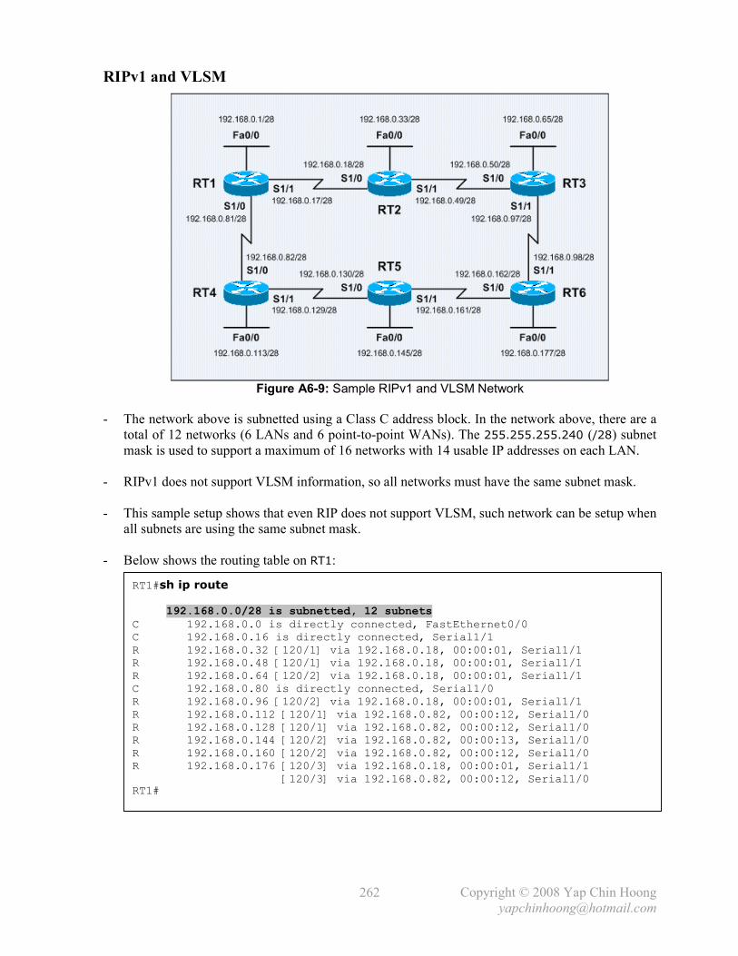
Copyright © 2008 Yap Chin Hoong
262
RIPv1 and VLSM
Figure A6-9: Sample RIPv1 and VLSM Network
- The network above is subnetted using a Class C address block. In the network above, there are a
total of 12 networks (6 LANs and 6 point-to-point WANs). The 255.255.255.240 (/28) subnet
mask is used to support a maximum of 16 networks with 14 usable IP addresses on each LAN.
- RIPv1 does not support VLSM information, so all networks must have the same subnet mask.
- This sample setup shows that even RIP does not support VLSM, such network can be setup when
all subnets are using the same subnet mask.
- Below shows the routing table on RT1:
RT1#sh ip route 192.168.0.0/28 is subnetted, 12 subnets C 192.168.0.0 is directly connected, FastEthernet0/0 C 192.168.0.16 is directly connected, Serial1/1 R 192.168.0.32 [120/1] via 192.168.0.18, 00:00:01, Serial1/1 R 192.168.0.48 [120/1] via 192.168.0.18, 00:00:01, Serial1/1 R 192.168.0.64 [120/2] via 192.168.0.18, 00:00:01, Serial1/1 C 192.168.0.80 is directly connected, Serial1/0 R 192.168.0.96 [120/2] via 192.168.0.18, 00:00:01, Serial1/1 R 192.168.0.112 [120/1] via 192.168.0.82, 00:00:12, Serial1/0 R 192.168.0.128 [120/1] via 192.168.0.82, 00:00:12, Serial1/0 R 192.168.0.144 [120/2] via 192.168.0.82, 00:00:13, Serial1/0 R 192.168.0.160 [120/2] via 192.168.0.82, 00:00:12, Serial1/0 R 192.168.0.176 [120/3] via 192.168.0.18, 00:00:01, Serial1/1 [120/3] via 192.168.0.82, 00:00:12, Serial1/0 RT1#
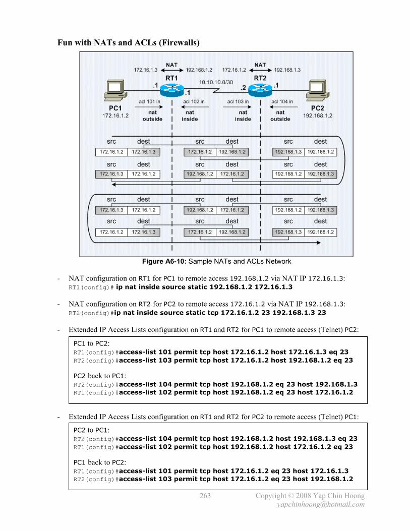
Copyright © 2008 Yap Chin Hoong
263
Fun with NATs and ACLs (Firewalls)
Figure A6-10: Sample NATs and ACLs Network
- NAT configuration on RT1 for PC1 to remote access 192.168.1.2 via NAT IP 172.16.1.3: RT1(config)# ip nat inside source static 192.168.1.2 172.16.1.3
- NAT configuration on RT2 for PC2 to remote access 172.16.1.2 via NAT IP 192.168.1.3: RT2(config)#ip nat inside source static tcp 172.16.1.2 23 192.168.1.3 23
- Extended IP Access Lists configuration on RT1 and RT2 for PC1 to remote access (Telnet) PC2:
- Extended IP Access Lists configuration on RT1 and RT2 for PC2 to remote access (Telnet) PC1:
PC1 to PC2: RT1(config)#access-list 101 permit tcp host 172.16.1.2 host 172.16.1.3 eq 23
RT2(config)#access-list 103 permit tcp host 172.16.1.2 host 192.168.1.2 eq 23
PC2 back to PC1: RT2(config)#access-list 104 permit tcp host 192.168.1.2 eq 23 host 192.168.1.3
RT1(config)#access-list 102 permit tcp host 192.168.1.2 eq 23 host 172.16.1.2
PC2 to PC1: RT2(config)#access-list 104 permit tcp host 192.168.1.2 host 192.168.1.3 eq 23
RT1(config)#access-list 102 permit tcp host 192.168.1.2 host 172.16.1.2 eq 23
PC1 back to PC2: RT1(config)#access-list 101 permit tcp host 172.16.1.2 eq 23 host 172.16.1.3
RT2(config)#access-list 103 permit tcp host 172.16.1.2 eq 23 host 192.168.1.2

Copyright © 2008 Yap Chin Hoong
264
- Below shows the NAT operations on RT1 and RT2 and ACL hit counts when PC1 accesses PC2:
RT1#debug ip nat IP NAT debugging is on RT1# 00:02:30: NAT: s=172.16.1.2, d=172.16.1.3->192.168.1.2 [14748] 00:02:32: NAT: s=172.16.1.2, d=172.16.1.3->192.168.1.2 [14748] 00:02:36: NAT: s=172.16.1.2, d=172.16.1.3->192.168.1.2 [14748] 00:02:38: NAT*: s=192.168.1.2->172.16.1.3, d=172.16.1.2 [19343] 00:02:38: NAT*: s=172.16.1.2, d=172.16.1.3->192.168.1.2 [14749] 00:02:38: NAT*: s=172.16.1.2, d=172.16.1.3->192.168.1.2 [14750] --- output omitted --- RT1#
RT1#sh access-list Extended IP access list 101 10 permit tcp host 172.16.1.2 host 172.16.1.3 eq telnet (28 matches) 20 permit tcp host 172.16.1.2 eq telnet host 172.16.1.3 Extended IP access list 102 10 permit tcp host 192.168.1.2 eq telnet host 172.16.1.2 (14 matches) 20 permit tcp host 192.168.1.2 host 172.16.1.2 eq telnet RT1#
RT1#sh ip nat statistics Total active translations: 1 (1 static, 0 dynamic; 0 extended) Outside interfaces: FastEthernet0/0 Inside interfaces: FastEthernet1/0 Hits: 36 Misses: 0 Expired translations: 0 Dynamic mappings: RT1# ---------------------------------------------------------------------- RT2# 00:02:31: NAT: s=172.16.1.2->192.168.1.3, d=192.168.1.2 [14748] 00:02:37: NAT*: s=192.168.1.2, d=192.168.1.3->172.16.1.2 [19343] 00:02:37: NAT*: s=172.16.1.2->192.168.1.3, d=192.168.1.2 [14749] --- output omitted ---
RT2#sh access-list Extended IP access list 103 10 permit tcp host 172.16.1.2 host 192.168.1.2 eq telnet (25 matches) 20 permit tcp host 172.16.1.2 eq telnet host 192.168.1.2 Extended IP access list 104 10 permit tcp host 192.168.1.2 eq telnet host 192.168.1.3 (14 matches) 20 permit tcp host 192.168.1.2 host 192.168.1.3 eq telnet RT2# ----------------------------------------------------------------------
PC1#telnet 172.16.1.3 Trying 172.16.1.3 ... Open User Access Verification Password: PC2>who Line User Host(s) Idle Location 0 con 0 idle 00:00:56 * 66 vty 0 idle 00:00:00 192.168.1.3 Interface User Mode Idle Peer Address PC2>

Copyright © 2008 Yap Chin Hoong
265
- Below shows the NAT operations on RT2 and RT1 and ACL hit counts when PC2 accesses PC1:
RT2#debug ip nat IP NAT debugging is on RT2# 00:04:42: NAT: s=192.168.1.2, d=192.168.1.3->172.16.1.2 [50878] 00:04:42: NAT*: s=172.16.1.2->192.168.1.3, d=192.168.1.2 [2634] 00:04:42: NAT*: s=192.168.1.2, d=192.168.1.3->172.16.1.2 [50879] 00:04:42: NAT*: s=192.168.1.2, d=192.168.1.3->172.16.1.2 [50880] --- output omitted --- RT2#
RT2#sh access-list Extended IP access list 103 10 permit tcp host 172.16.1.2 host 192.168.1.2 eq telnet 20 permit tcp host 172.16.1.2 eq telnet host 192.168.1.2 (17 matches) Extended IP access list 104 10 permit tcp host 192.168.1.2 eq telnet host 192.168.1.3 20 permit tcp host 192.168.1.2 host 192.168.1.3 eq telnet (25 matches) RT2#
RT2#sh ip nat statistics Total active translations: 1 (1 static, 0 dynamic; 0 extended) Outside interfaces: FastEthernet0/0 Inside interfaces: FastEthernet1/0 Hits: 40 Misses: 0 Expired translations: 0 Dynamic mappings: RT2# ---------------------------------------------------------------------- RT1# 00:04:43: NAT: s=192.168.1.2->172.16.1.3, d=172.16.1.2 [50878] 00:04:43: NAT*: s=172.16.1.2, d=172.16.1.3->192.168.1.2 [2634] 00:04:43: NAT*: s=192.168.1.2->172.16.1.3, d=172.16.1.2 [50879] 00:04:43: NAT*: s=172.16.1.2, d=172.16.1.3->192.168.1.2 [2635] --- output omitted ---
RT1#sh access-list Extended IP access list 101 10 permit tcp host 172.16.1.2 host 172.16.1.3 eq telnet 20 permit tcp host 172.16.1.2 eq telnet host 172.16.1.3 (17 matches) Extended IP access list 102 10 permit tcp host 192.168.1.2 eq telnet host 172.16.1.2 20 permit tcp host 192.168.1.2 host 172.16.1.2 eq telnet (25 matches) RT1# ----------------------------------------------------------------------
PC2#telnet 192.168.1.3 Trying 192.168.1.3 ... Open User Access Verification Password: PC1> PC1>who Line User Host(s) Idle Location 0 con 0 idle 00:00:35 * 66 vty 0 idle 00:00:00 172.16.1.3 Interface User Mode Idle Peer Address PC1>

Copyright © 2008 Yap Chin Hoong
266
NAT with Virtual Interface
Figure A6-11: NAT with Virtual Interface
- In this scenario, PC1 and PC2 are belong to 2 different organizations and must be assigned with
IP addresses in 192.168.1.0/24 and 10.1.1.0/24 subnets respectively due to some reasons, eg:
network overlapping and not feasible to have subnet other than the mentioned subnets.
- Organization A has no issue introducing routing to 10.1.1.0/24 into its network; but
Organization B unable to introduce routing to 192.168.1.0/24 due to its network design and IP
addressing plan.
- The solution is assign 10.2.2.1/24 to RT1 Lo0, which is supposed to be assigned to RT1 Fa1/0;
followed by translating 192.168.1.2 to 10.2.2.2 – the IP address which Organization B expects.
- NAT configuration on RT1:
- The NAT debug messages on RT1 shows the translation between 192.168.1.2 and 10.2.2.2:
! interface Loopback0 ip address 10.2.2.1 255.255.255.0 ip nat outside ! interface Serial0/0 ip address 10.10.10.1 255.255.255.0 ip nat outside ! interface FastEthernet1/0 ip address 192.168.1.1 255.255.255.0 ip nat inside ! router eigrp 100 network 10.0.0.0 no auto-summary ! ip nat inside source static 192.168.1.2 10.2.2.2 !
RT1#debug ip nat IP NAT debugging is on RT1# 00:07:18: NAT*: s=192.168.1.2->10.2.2.2, d=10.1.1.2 [10] 00:07:18: NAT*: s=10.1.1.2, d=10.2.2.2->192.168.1.2 [10] 00:07:18: NAT*: s=192.168.1.2->10.2.2.2, d=10.1.1.2 [11] 00:07:18: NAT*: s=10.1.1.2, d=10.2.2.2->192.168.1.2 [11]

Copyright © 2008 Yap Chin Hoong
267
- RT2 routing table showing that 192.168.1.0/24 network is not introduced into Organization B:
NAT Attack Session – ip nat inside source and ip nat outside source
Figure A6-12: NAT Attack Session
RT2#sh ip route Gateway of last resort is not set 10.0.0.0/24 is subnetted, 3 subnets D 10.2.2.0 [90/2297856] via 10.10.10.1, 00:10:46, Serial0/0 C 10.10.10.0 is directly connected, Serial0/0 C 10.1.1.0 is directly connected, FastEthernet1/0 RT2#

Copyright © 2008 Yap Chin Hoong
268
- This section shows how to achieve the same result – ServerA communicates with PC1 using
172.16.10.10 NAT IP instead of 192.168.1.10 real IP with inside source and outside source
NAT configurations. This is a knowledge attack session which strengthens the understanding of
NAT terminologies and operations.
- The *** indicates where the NAT operations are initiated according to the ip nat commands.
- Note: A router does not require a physical nor logical interface to reside in the NAT IP address
subnet for the operation of NAT – 172.16.10.0/24 in this case. As compared to the previous
section – NAT with Virtual Interface, which the router has a logical loopback interface and
advertising the NAT IP subnet (10.2.2.0/24) using EIGRP.
- RT1 configuration for ip nat inside source operation:
- Below shows the NAT debug messages on RT1 for the configuration above:
- RT1 configuration for ip nat outside source operation:
! interface FastEthernet0/0 ip address 172.16.1.2 255.255.255.0 ip nat outside ! interface FastEthernet1/0 ip address 192.168.1.1 255.255.255.0 ip nat inside ! ip nat inside source static 192.168.1.10 172.16.10.10 !
! interface FastEthernet0/0 ip address 172.16.1.2 255.255.255.0 ip nat inside ! interface FastEthernet1/0 ip address 192.168.1.1 255.255.255.0 ip nat outside ! ip nat outside source static 192.168.1.10 172.16.10.10 ip route 172.16.10.10 255.255.255.255 FastEthernet1/0 !
RT1#debug ip nat IP NAT debugging is on RT1# 00:04:29: NAT*: s=10.10.10.10, d=172.16.10.10->192.168.1.10 [15] 00:04:29: NAT*: s=192.168.1.10->172.16.10.10, d=10.10.10.10 [15] 00:04:29: NAT*: s=10.10.10.10, d=172.16.10.10->192.168.1.10 [16] 00:04:29: NAT*: s=192.168.1.10->172.16.10.10, d=10.10.10.10 [16] 00:04:29: NAT*: s=10.10.10.10, d=172.16.10.10->192.168.1.10 [17] 00:04:29: NAT*: s=192.168.1.10->172.16.10.10, d=10.10.10.10 [17]

Copyright © 2008 Yap Chin Hoong
269
Complex ACL
Figure A6-13: Sample Complex ACL Network
- The user requirement for the sample network above is to deny all access (Microsoft file sharing,
Remote Desktop, ICMP ping, etc) from PCs in VLAN 11, 12, and 13 to the PCs in HR Network.
- Below shows a sample solution by applying an inbound access list to RT1 Fa1 interface:
access-list 101 deny tcp 11.11.11.0 0.0.0.255 eq 135 10.10.11.0 0.0.0.255 access-list 101 deny tcp 11.11.11.0 0.0.0.255 eq 139 10.10.11.0 0.0.0.255 access-list 101 deny tcp 11.11.11.0 0.0.0.255 eq 445 10.10.11.0 0.0.0.255 access-list 101 deny udp 11.11.11.0 0.0.0.255 eq 137 10.10.11.0 0.0.0.255 access-list 101 deny udp 11.11.11.0 0.0.0.255 eq 138 10.10.11.0 0.0.0.255 access-list 101 deny tcp 11.11.11.0 0.0.0.255 eq 3389 10.10.11.0 0.0.0.255 access-list 101 deny icmp 11.11.11.0 0.0.0.255 10.10.11.0 0.0.0.255 echo-reply ! -------------------------------------------------- access-list 101 deny tcp 11.11.11.0 0.0.0.255 eq 135 10.10.12.0 0.0.0.255 access-list 101 deny tcp 11.11.11.0 0.0.0.255 eq 139 10.10.12.0 0.0.0.255 access-list 101 deny tcp 11.11.11.0 0.0.0.255 eq 445 10.10.12.0 0.0.0.255 access-list 101 deny udp 11.11.11.0 0.0.0.255 eq 137 10.10.12.0 0.0.0.255 access-list 101 deny udp 11.11.11.0 0.0.0.255 eq 138 10.10.12.0 0.0.0.255 access-list 101 deny tcp 11.11.11.0 0.0.0.255 eq 3389 10.10.12.0 0.0.0.255 access-list 101 deny icmp 11.11.11.0 0.0.0.255 10.10.12.0 0.0.0.255 echo-reply ! -------------------------------------------------- access-list 101 deny tcp 11.11.11.0 0.0.0.255 eq 135 10.10.13.0 0.0.0.255 access-list 101 deny tcp 11.11.11.0 0.0.0.255 eq 139 10.10.13.0 0.0.0.255 access-list 101 deny tcp 11.11.11.0 0.0.0.255 eq 445 10.10.13.0 0.0.0.255 access-list 101 deny udp 11.11.11.0 0.0.0.255 eq 137 10.10.13.0 0.0.0.255 access-list 101 deny udp 11.11.11.0 0.0.0.255 eq 138 10.10.13.0 0.0.0.255 access-list 101 deny tcp 11.11.11.0 0.0.0.255 eq 3389 10.10.13.0 0.0.0.255 access-list 101 deny icmp 11.11.11.0 0.0.0.255 10.10.13.0 0.0.0.255 echo-reply ! -------------------------------------------------- access-list 101 permit ip any any ! interface FastEthernet1 ip address 11.11.11.1 255.255.255.0 ip access-group 101 in !

Copyright © 2008 Yap Chin Hoong
270
The Access Control List established Keyword
- The established keyword is only applicable to TCP access list entries to match TCP segments
that have the ACK and / or RST control bit set (regardless of the source and destination ports),
which assumes that a TCP connection has already been established. The non-matching cases are
initial TCP connection-establishment segments which have only the SYN bit set.
- A typically usage is to distinguish the connections originating inside from connections
originating elsewhere. Figure A6-14 shows a scenario which allowing internal systems to initiate
Telnet connections to any Internet site (outside network), but not the other way around. A simple
solution is to block incoming packets that don’t have the ACK or RST bits set by using the
established keyword, which permitting return traffic for connections that are established and
initiated from the inside, and denying connections initiated from outside to inside.
Figure A6-14: Sample ACL established Network I
- Note: This method of blocking unwanted traffic originating outside the network can be
circumvented – it is possible to forge a packet with the appropriate bits set.
- Another usage is to allow connections to be initiated from client systems only, but not from the
server to the others. This can prevent abuse from the server and tighten the server to offer only
the necessary services.
Figure A6-15: Sample ACL established Network II
- The access-list 101 permit tcp any any established is equivalent to access-list 101
permit tcp any any ack rst.

Copyright © 2008 Yap Chin Hoong
271
The Access Control List fragments Keyword
- The fragments keyword indicates that an access list entry is only applied to non-initial packet
fragments (L3). The fragment is either permitted or denied accordingly. The default behavior is
without the fragments keyword.
- The fragments keyword cannot be configured for an access list entry that contains any L4
information. Ex: access-list 101 permit tcp host 1.1.1.1 host 2.2.2.2 eq 80 fragments
is invalid.
- Without the fragments keyword (default), an access list entry that contains only L3 information
(eg: access-list 101 permit ip host 10.10.10.1 host 10.10.10.2) is matched with all
types of packets – non-fragmented packets, initial and non-initial packet fragments.
Note: The fragments keyword indicates that an access list entry will be matched with non-
initial fragments.
- Without the fragments keyword (default), an access list entry that contains L3 and L4
information (eg: access-list 101 permit tcp host 10.10.10.1 host 10.10.10.2 eq telnet)
is matched with non-fragmented packets and initial packet fragments and is either permitted or
denied accordingly.
o When a permit statement (without the fragments keyword) is matched with non-initial packet fragments, the non-initial fragments are permitted.
o When a deny statement (without the fragments keyword) is matched with non-initial packet fragments, the next access list entry is processed, and the fragments are not being
denied!
Summary: The deny statements (without the fragments keyword) are handled differently for
non-initial packet fragments than the permit statements (without the fragments keyword).
- Do not simply add the fragments keyword to every access list entry, as the 1st fragment (initial
fragment) will not be matched with an access list permit or deny entry that contains the
fragments keyword – the packet is compared to the next access list entry, until it is either
permitted or denied by an access list entry that does not contain the fragments keyword.
Therefore, 2 deny access list entries are needed for every deny entry. The 1st deny entry of the
pair will not include the fragments keyword to be applied for initial fragments; the 2nd deny
entry of the pair will include the fragments keyword to be applied for non-initial fragments.
- Note: Packet fragments are considered individual packets and each is counted individually as a
packet in access list accounting.
- When there are multiple deny access list entries for a particular host with different L4 ports,
only a single deny access list entry with the fragments keyword for the host is required. All
the packet fragments are handled in the same manner by the access list.
- The fragment control feature affect policy routing if the policy routing is based on the match ip
address command and the access list has entries that match L4 through L7 information.
It is possible for non-initial fragments to be matched with the access list and are policy routed,
even if the 1st fragment was not policy routed (or the reverse).
- This feature provides a better match capability between initial and non-initial fragments and
hence allows the configuration of advanced policy routing.

Copyright © 2008 Yap Chin Hoong
272
Switch Port Access Control Lists
- Switch port ACLs can only be applied as inbound lists with extended named access lists to
L2 switch interfaces.
- MAC extended access lists perform filtering based on the source and destination MAC addresses,
as well as the optional EtherType information.
- The question is do we really want to deny MAC addresses? Deny access based on the EtherType
field in the Ethernet frame header is usually the better option.
- Blocking 0x0800 would mean blocking all IP traffic, which could be handy in the future when
forcing everyone to run IPv6!
Switch#conf t Enter configuration commands, one per line. End with CNTL/Z.
Switch(config)#mac access-list ? extended Extended Access List
Switch(config)#mac access-list extended ? WORD access-list name
Switch(config)#mac access-list extended example01
Switch(config-ext-macl)#deny any host ? H.H.H 48-bit destination MAC address
Switch(config-ext-macl)#deny any host 1111.1111.1111
Switch(config-ext-macl)#permit any any
Switch(config-ext-macl)#^Z Switch#
Switch#sh access-list Extended MAC access list example01 deny any host 1111.1111.1111 permit any any Switch#
Switch#conf t Enter configuration commands, one per line. End with CNTL/Z.
Switch(config)#int fa0/1
Switch(config-if)#mac access-group example01 ? in Apply to Ingress
Switch(config-if)#mac access-group example01 in
Switch(config-if)#^Z Switch#
Switch#sh mac access-group int fa0/1 Interface FastEthernet0/1: Inbound access-list is example01 Switch#

Copyright © 2008 Yap Chin Hoong
273
- MAC access lists can filter traffic based on various EtherType:
Advanced Access Control List Configurations
Figure A6-16: Network Setup for Advanced Access Control List Configurations
- Dynamic access lists or Lock-and-Key Security is a type of ACL traffic filtering security
feature that dynamically filters IP protocol traffic. Users that would like to traverse through the
router are normally blocked by the extended ACL until they authenticates themselves to the
router through a Telnet session with a username and password. After the user is authenticated,
the Telnet connection is dropped, and a dynamic ACL entry is appended to the existing extended
ACL to temporary allow the user to access resources that are blocked behind the router for
certain duration until the specified timeout expires.
Switch(config-ext-macl)#deny any any ? <0-65535> An arbitrary EtherType in decimal, hex, or octal aarp EtherType: AppleTalk ARP amber EtherType: DEC-Amber appletalk EtherType: AppleTalk/EtherTalk cos CoS value dec-spanning EtherType: DEC-Spanning-Tree decnet-iv EtherType: DECnet Phase IV diagnostic EtherType: DEC-Diagnostic dsm EtherType: DEC-DSM etype-6000 EtherType: 0x6000 etype-8042 EtherType: 0x8042 lat EtherType: DEC-LAT lavc-sca EtherType: DEC-LAVC-SCA lsap LSAP value mop-console EtherType: DEC-MOP Remote Console mop-dump EtherType: DEC-MOP Dump msdos EtherType: DEC-MSDOS mumps EtherType: DEC-MUMPS netbios EtherType: DEC-NETBIOS vines-echo EtherType: VINES Echo vines-ip EtherType: VINES IP xns-idp EtherType: XNS IDP <cr>

Copyright © 2008 Yap Chin Hoong
274
- Below shows a sample Dynamic Access Lists configuration on RT1:
[1]
[1]
[2]
[3]
[4]
Note: Configuring the autocommand access-enable host timeout 10 line command under
line vty 0 4 which is normally found in other configuration examples is not as flexible as
configuring the autocommand for particular users with the username privileged commands.
- Below describes the configuration steps for the sample dynamic access list configuration:
1) Create a user authentication method on the router. This can either be local authentication
or remote security database using RADIUS or TACACS+ server. This sample
configuration defines a user named remote with a password of cisco123 and a line of
command (access-enable host timeout 10 in this case) which will be issued
automatically (due to the autocommand keyword) after the user is authenticated via the
Telnet session to the router.
Note: The access-enable EXEC command creates a temporary access-list entry.
2) Define an extended ACL to allow only Telnet access to the router (for authentication),
but block all other traffic.
3) Create a dynamic ACL that applies to the extended access list 101 after the user is
authenticated via the Telnet session to the router.
4) Since this sample configuration is using local authentication, the router needs to be
configured to locally authenticate when a user connects to its VTY ports.
- Reflexive access lists are dynamic access lists that allow traffic based on the detection of traffic
in the opposite direction as well as upper-layer session information. They often permit outbound
traffic which originated from an inside network but deny inbound traffic which originated from
an outside network.
- Reflexive ACLs cannot be defined with standard or numbered ACLs; they can only be defined
with extended named ACLs and can be used along with other standard or extended ACLs.
They are temporary entries that are created when a new IP session begins and are removed when
the session ends (when the last segment with FIN or RST is seen or the idle timeout expires).
Reflexive ACLs are not applied directly to an interface, but are “nested” within an extended
named IP ACL that is applied to an interface.
Router(config)#username remote password cisco123
Router(config)#username remote autocommand access-enable host timeout 10
Router(config)#access-list 101 permit tcp any host 172.16.0.1 eq telnet
Router(config)#access-list 101 dynamic remote-access01 timeout 15 permit ip
172.16.0.0 0.0.0.255 10.10.10.0 0.0.0.255
Router(config)#int fa0/0
Router(config-if)#ip access-group 101 in
Router(config-if)#exit
Router(config)#line vty 0 4
Router(config-line)#login local
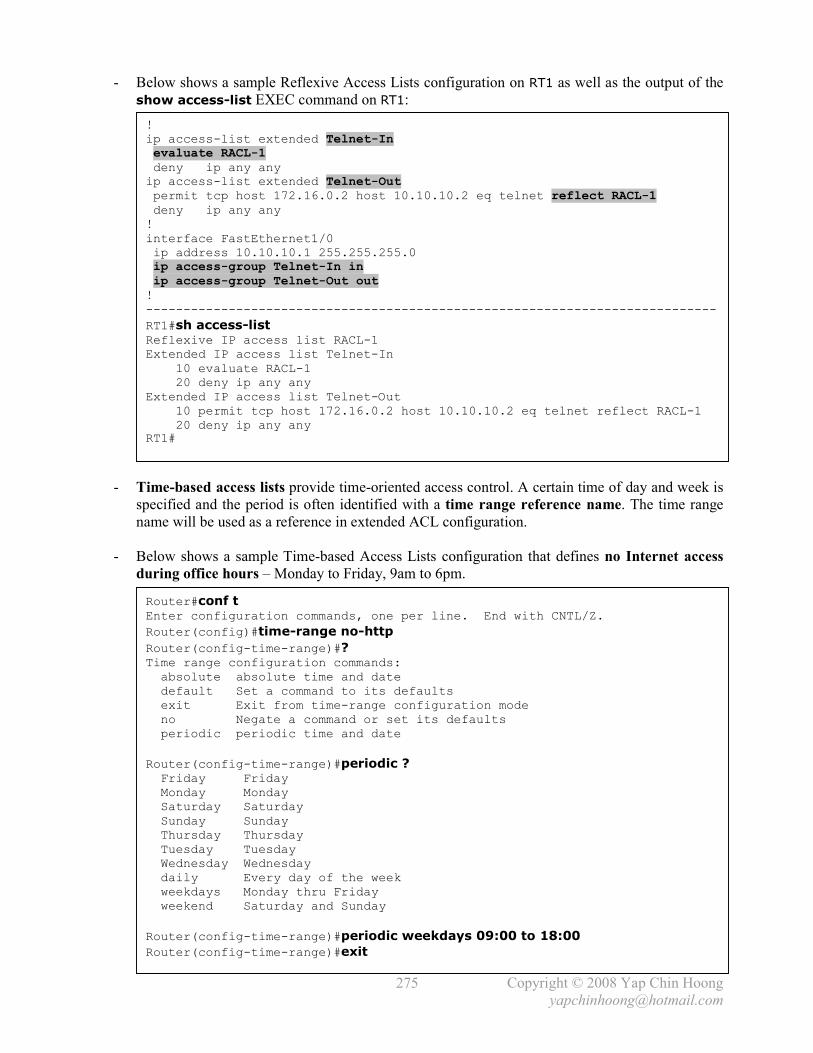
Copyright © 2008 Yap Chin Hoong
275
- Below shows a sample Reflexive Access Lists configuration on RT1 as well as the output of the
show access-list EXEC command on RT1:
- Time-based access lists provide time-oriented access control. A certain time of day and week is
specified and the period is often identified with a time range reference name. The time range
name will be used as a reference in extended ACL configuration.
- Below shows a sample Time-based Access Lists configuration that defines no Internet access
during office hours – Monday to Friday, 9am to 6pm.
Router#conf t Enter configuration commands, one per line. End with CNTL/Z.
Router(config)#time-range no-http
Router(config-time-range)#? Time range configuration commands: absolute absolute time and date default Set a command to its defaults exit Exit from time-range configuration mode no Negate a command or set its defaults periodic periodic time and date
Router(config-time-range)#periodic ? Friday Friday Monday Monday Saturday Saturday Sunday Sunday Thursday Thursday Tuesday Tuesday Wednesday Wednesday daily Every day of the week weekdays Monday thru Friday weekend Saturday and Sunday
Router(config-time-range)#periodic weekdays 09:00 to 18:00
Router(config-time-range)#exit
! ip access-list extended Telnet-In evaluate RACL-1 deny ip any any ip access-list extended Telnet-Out permit tcp host 172.16.0.2 host 10.10.10.2 eq telnet reflect RACL-1 deny ip any any ! interface FastEthernet1/0 ip address 10.10.10.1 255.255.255.0 ip access-group Telnet-In in ip access-group Telnet-Out out ! ----------------------------------------------------------------------------
RT1#sh access-list Reflexive IP access list RACL-1 Extended IP access list Telnet-In 10 evaluate RACL-1 20 deny ip any any Extended IP access list Telnet-Out 10 permit tcp host 172.16.0.2 host 10.10.10.2 eq telnet reflect RACL-1 20 deny ip any any RT1#

Copyright © 2008 Yap Chin Hoong
276
- Context-Based Access Control (CBAC) is a Cisco IOS Firewall feature which provides
advanced traffic filtering functionality and secure access control on a per-application basis.
CBAC is often referred to as Stateful IOS Firewall Inspection.
- CBAC provides multiple levels of network protection with the following functions:
Traffic Filtering Intelligently filters TCP and UDP segments based on application
layer protocol information (eg: FTP connection information).
Without CBAC, traffic filtering is limited to access list
implementations which only able to examine the information at the
network and transport layers. Due to the capability of learning the
state information of the sessions and control them, CBAC supports
filtering for application layer protocols that involve multiple
channels created as a result of negotiations in the control channel.
Many multimedia protocols and other protocols (eg: FTP, RPC,
SQL*Net) involve multiple channels in their communications.
CBAC can be configured to inspect application layer traffic for
sessions and connections that are originated from either side of a
firewall and permit the specified traffic through it; hence it can be
used for intranet, extranet, and Internet perimeters of a network.
Router(config)#ip access-list extended Time_no-http
Router(config-ext-nacl)#deny tcp any any eq www time-range no-http
Router(config-ext-nacl)#permit tcp any any
Router(config-ext-nacl)#exit
Router(config)#int fa0/0
Router(config-if)#ip access-group Time_no-http in
Router(config-if)#^Z Router#
Router#sh clock 10:00:01.835 UTC Sun Jan 6 2008
Router#sh time-range time-range entry: no-http (inactive) periodic weekdays 9:00 to 18:00 used in: IP ACL entry
Router#sh access-list Extended IP access list Time_no-http deny tcp any any eq www time-range no-http (inactive) permit tcp any any Router# ----------------------------------------------------------------------------
Router#sh clock 10:00:01.139 UTC Mon Jan 7 2008
Router#sh time-range time-range entry: no-http (active) periodic weekdays 9:00 to 18:00 used in: IP ACL entry
Router#sh access-list Extended IP access list Time_no-http deny tcp any any eq www time-range no-http (active) permit tcp any any Router#

Copyright © 2008 Yap Chin Hoong
277
Traffic Inspection Inspects traffic that passes through a firewall to discover and
manage state information for TCP and UDP sessions. The state
information is used to create temporary openings in the access lists
to allow return traffic for permissible sessions. With the capabilities
of inspecting and maintaining TCP and UDP session information,
CBAC is able to detect and prevent certain types of network
attacks, eg: SYN Flooding. CBAC helps to protect against DoS
attacks with the following approaches:
i) Inspects TCP sequence numbers in to see if they are within
expected ranges and drops the suspicious packets.
ii) Drops half-open connections, which require firewall processing and memory resources to maintain.
iii) Detects unusually high rates of new connections and issue alert messages.
Besides that, CBAC can also help to protect against certain DoS
attacks which involve fragmented IP packets. Even though the
firewall prevents an attacker from establishing actual connections to
an end system, the attacker can disrupt services on the end system
by sending many non-initial IP fragments, which can eventually tie
up resources on the target end system as it tries to reassemble the
incomplete packets.
Alerts and Audit Trails Generates real-time alerts and audit trails for tracking suspicious
activities and network transactions (eg: time stamps, source and
destination hosts, ports, total number of transmitted bytes, etc).
With CBAC inspection rules, alerts and audit trail information can
be configured on a per-application protocol basis.
Intrusion Prevention Provides a limited amount of intrusion detection to protect against
specific SMTP attacks. With intrusion detection, SYSLOG
messages are reviewed and monitored for specific attack signatures.
When CBAC detects an attack, it resets the offending connections
and generates a SYSLOG message to a SYSLOG server.
- CBAC only effective for the specified protocols. If a particular is not specified for CBAC, the
existing access lists will determine how the traffic for the particular protocol is being processed.
No temporary openings will be created for protocols that are not specified for CBAC inspection.
- CBAC can only provide protection against certain types of attacks, but not all types of attacks.
CBAC should not be considered as a perfect defense; there is no such thing as a perfect defense.
CBAC detects and prevents most types of popular network attacks.
- Authentication Proxy requires the Cisco IOS Firewall feature set as well. It is able to
authenticate inbound and/or outbound users and grant the access to the resources that are blocked
behind a firewall. By launching a browser to access resources behind the firewall, the firewall
would respond to the HTTP session and redirect the user to an authentication page which a valid
username and password must be supplied for authentication purpose. An authentication entry
will be created for the user. There is no intervention by the authentication proxy for subsequent
HTTP sessions through the firewall as long as a valid authentication entry exists for the user.

Copyright © 2008 Yap Chin Hoong
278
Optional PPP Commands
- The compress predictor interface subcommand enables the PPP Predictor compression
algorithm; while the compress stac interface subcommand enables the PPP Stacker
compression algorithm.
- The ppp quality {percent} interface subcommand ensures a PPP link meets a percentage of
quality during the optional link-quality determination phase in the PPP link establishment phase.
This is to determine whether the link quality is sufficient to bring up any Layer 3 protocols.
The link will not be established if it does not meet the percentage level.
Note: PPP link establishment is handled by Link Control Protocol (LCP).
- The ppp authentication {pap | chap} {chap | pap} interface subcommand defines a PPP
link to use the 1st authentication protocol, but will try 2nd authentication protocol if the 1st
authentication protocol fails or rejected by the other side.
- The ppp sent-username {username} password {password} interface subcommand is
mandate in PAP configuration.
- In PPP authentication configuration, passwords are case sensitive but usernames are not case-
sensitive.
Unidirectional PPP PAP Authentication
Figure A6-17: Unidirectional PPP PAP Authentication
- Unidirectional PPP PAP authentication configuration on Client:
Note: The ppp authentication pap interface subcommand is not required on Client.
interface Serial0/0 ip address 10.10.10.1 255.255.255.252 encapsulation ppp ppp direction callout ppp pap sent-username Client password 0 cisco

Copyright © 2008 Yap Chin Hoong
279
- Unidirectional PPP PAP authentication configuration on NAS:
Note: The callin keyword of the ppp authentication pap interface subcommand is optional
- A router configured with the ppp authentication pap interface subcommand will use PAP to
verify the identity of the peer, which means that the peer must present its username and password
to the local device for verification. The local device would use the local username-based
authentication system to verify and authenticate its peer.
- The function of the username {remote-username} password {passwd} statement is
different for PAP and CHAP. With PAP, it is only used to verify that an incoming username and
password; whereas CHAP uses it to generate the response to a challenge and verify a response.
- For one-way PAP authentication, the username {remote-hostname} password {passwd}
statement is only required on the called device to verify the username and password sent by the
calling device; whereas for two-way PAP authentication, it is required on both devices.
- A router configured with the ppp authentication pap callin interface subcommand
configured will only authenticate the peer during incoming calls – it will not authenticate the
peer for outgoing calls.
- The ppp pap sent-username {local-username} password {passwd} interface
subcommand is configured on the calling device to authenticate itself to a remote called device.
The remote device must have the same set of username – password statement configured.
- The ppp direction {callin | callout | dedicated} interface subcommand is introduced in
Cisco IOS Release 12.2T. This command is useful when a router is connected to an interface
type where there is no inherent call direction, eg: a back-to-back or leased-line connection.
username Client password 0 cisco ! interface Serial0/0 ip address 10.10.10.2 255.255.255.252 encapsulation ppp ppp authentication pap [callin] ppp direction callin

Copyright © 2008 Yap Chin Hoong
280
- Below shows the output of the PPP authentication debug messages for a successful unidirectional
PAP authentication on Client:
Client#sh debug PPP: PPP authentication debugging is on PPP protocol negotiation debugging is on
Client#conf t Enter configuration commands, one per line. End with CNTL/Z.
Client(config)#int s1/0
Client(config-if)#no shut Client(config-if)# 00:07:14: %LINK-3-UPDOWN: Interface Serial0/0, changed state to up 00:07:14: Se0/0 PPP: Using configured call direction 00:07:14: Se0/0 PPP: Treating connection as a callout 00:07:14: Se0/0 PPP: Session handle[5A000003] Session id[25] 00:07:14: Se0/0 PPP: Phase is ESTABLISHING, Active Open 00:07:14: Se0/0 PPP: Authorization required 00:07:14: Se0/0 PPP: No remote authentication for call-out 00:07:14: Se0/0 LCP: O CONFREQ [Closed] id 25 len 10 00:07:14: Se0/0 LCP: MagicNumber 0x0013D707 (0x05060013D707) 00:07:14: Se0/0 LCP: I CONFREQ [REQsent] id 83 len 14 00:07:14: Se0/0 LCP: AuthProto PAP (0x0304C023) 00:07:14: Se0/0 LCP: MagicNumber 0x0113BFC6 (0x05060113BFC6) 00:07:14: Se0/0 LCP: O CONFACK [REQsent] id 83 len 14 00:07:14: Se0/0 LCP: AuthProto PAP (0x0304C023) 00:07:14: Se0/0 LCP: MagicNumber 0x0113BFC6 (0x05060113BFC6) 00:07:14: Se0/0 LCP: I CONFACK [ACKsent] id 25 len 10 00:07:14: Se0/0 LCP: MagicNumber 0x0013D707 (0x05060013D707) 00:07:14: Se0/0 LCP: State is Open 00:07:14: Se0/0 PPP: No authorization without authentication 00:07:15: Se0/0 PPP: Phase is AUTHENTICATING, by the peer 00:07:15: Se0/0 PAP: Using hostname from interface PAP 00:07:15: Se0/0 PAP: Using password from interface PAP 00:07:15: Se0/0 PAP: O AUTH-REQ id 25 len 17 from "Client" 00:07:15: Se0/0 PAP: I AUTH-ACK id 25 len 5 00:07:15: Se0/0 PPP: Phase is FORWARDING, Attempting Forward 00:07:15: Se0/0 PPP: Queue IPCP code[1] id[1] 00:07:15: Se0/0 PPP: Phase is ESTABLISHING, Finish LCP 00:07:15: Se0/0 PPP: Phase is UP 00:07:15: Se0/0 IPCP: O CONFREQ [Closed] id 1 len 10 00:07:15: Se0/0 IPCP: Address 10.10.10.1 (0x03060A0A0A01) 00:07:15: Se0/0 CDPCP: O CONFREQ [Closed] id 1 len 4 00:07:15: Se0/0 PPP: Process pending ncp packets 00:07:15: Se0/0 IPCP: Redirect packet to Se1/0 00:07:15: Se0/0 IPCP: I CONFREQ [REQsent] id 1 len 10 00:07:15: Se0/0 IPCP: Address 10.10.10.2 (0x03060A0A0A02) 00:07:15: Se0/0 IPCP: O CONFACK [REQsent] id 1 len 10 00:07:15: Se0/0 IPCP: Address 10.10.10.2 (0x03060A0A0A02) 00:07:15: Se0/0 CDPCP: I CONFREQ [REQsent] id 1 len 4 00:07:15: Se0/0 CDPCP: O CONFACK [REQsent] id 1 len 4 00:07:15: Se0/0 IPCP: I CONFACK [ACKsent] id 1 len 10 00:07:15: Se0/0 IPCP: Address 10.10.10.1 (0x03060A0A0A01) 00:07:15: Se0/0 IPCP: State is Open 00:07:15: Se0/0 IPCP: Add link info for cef entry 10.1.1.2 00:07:15: Se0/0 IPCP: Install route to 10.1.1.2 00:07:15: Se0/0 CDPCP: I CONFACK [ACKsent] id 1 len 4 00:07:15: Se0/0 CDPCP: State is Open 00:07:16: %LINEPROTO-5-UPDOWN: Line protocol on Interface Serial0/0, changed state to up Client(config-if)#

Copyright © 2008 Yap Chin Hoong
281
- Below shows the output of the PPP authentication debug messages for a successful unidirectional
PAP authentication on NAS:
NAS# 00:07:08: Se0/0 LCP: I CONFREQ [Listen] id 25 len 10 00:07:08: Se0/0 LCP: MagicNumber 0x0013D707 (0x05060013D707) 00:07:08: Se0/0 PPP: Authorization required 00:07:08: Se0/0 LCP: O CONFREQ [Listen] id 83 len 14 00:07:08: Se0/0 LCP: AuthProto PAP (0x0304C023) 00:07:08: Se0/0 LCP: MagicNumber 0x0113BFC6 (0x05060113BFC6) 00:07:08: Se0/0 LCP: O CONFACK [Listen] id 25 len 10 00:07:08: Se0/0 LCP: MagicNumber 0x0013D707 (0x05060013D707) 00:07:09: Se0/0 LCP: I CONFACK [ACKsent] id 83 len 14 00:07:09: Se0/0 LCP: AuthProto PAP (0x0304C023) 00:07:09: Se0/0 LCP: MagicNumber 0x0113BFC6 (0x05060113BFC6) 00:07:09: Se0/0 LCP: State is Open 00:07:09: Se0/0 PPP: Phase is AUTHENTICATING, by this end 00:07:09: Se0/0 PAP: I AUTH-REQ id 25 len 17 from "Client" 00:07:09: Se0/0 PAP: Authenticating peer Client 00:07:09: Se0/0 PPP: Phase is FORWARDING, Attempting Forward 00:07:09: Se0/0 PPP: Phase is AUTHENTICATING, Unauthenticated User 00:07:09: Se0/0 PPP: Sent PAP LOGIN Request 00:07:09: Se0/0 PPP: Received LOGIN Response PASS 00:07:09: Se0/0 PPP: Phase is FORWARDING, Attempting Forward 00:07:09: Se0/0 PPP: Phase is AUTHENTICATING, Authenticated User 00:07:09: Se0/0 PPP: Sent LCP AUTHOR Request 00:07:09: Se0/0 PPP: Sent IPCP AUTHOR Request 00:07:09: Se0/0 LCP: Received AAA AUTHOR Response PASS 00:07:09: Se0/0 IPCP: Received AAA AUTHOR Response PASS 00:07:09: Se0/0 PAP: O AUTH-ACK id 25 len 5 00:07:09: Se0/0 PPP: Phase is UP 00:07:09: Se0/0 IPCP: O CONFREQ [Closed] id 1 len 10 00:07:09: Se0/0 IPCP: Address 10.10.10.2 (0x03060A0A0A02) 00:07:09: Se0/0 PPP: Sent CDPCP AUTHOR Request 00:07:09: Se0/0 PPP: Process pending ncp packets 00:07:09: Se0/0 CDPCP: Received AAA AUTHOR Response PASS 00:07:09: Se0/0 CDPCP: O CONFREQ [Closed] id 1 len 4 00:07:09: Se0/0 IPCP: I CONFREQ [REQsent] id 1 len 10 00:07:09: Se0/0 IPCP: Address 10.10.10.1 (0x03060A0A0A01) 00:07:09: Se0/0 AAA/AUTHOR/IPCP: Start. Her address 10.1.1.1, we want 0.0.0.0 00:07:09: Se0/0 PPP: Sent IPCP AUTHOR Request 00:07:09: Se0/0 AAA/AUTHOR/IPCP: Reject 10.1.1.1, using 0.0.0.0 00:07:09: Se0/0 AAA/AUTHOR/IPCP: Done. Her address 10.1.1.1, we want 0.0.0.0 00:07:09: Se0/0 IPCP: O CONFACK [REQsent] id 1 len 10 00:07:09: Se0/0 IPCP: Address 10.10.10.1 (0x03060A0A0A01) 00:07:09: Se0/0 CDPCP: I CONFREQ [REQsent] id 1 len 4 00:07:09: Se0/0 CDPCP: O CONFACK [REQsent] id 1 len 4 00:07:09: Se0/0 IPCP: I CONFACK [ACKsent] id 1 len 10 00:07:09: Se0/0 IPCP: Address 10.10.10.2 (0x03060A0A0A02) 00:07:09: Se0/0 IPCP: State is Open 00:07:09: Se0/0 CDPCP: I CONFACK [ACKsent] id 1 len 4 00:07:09: Se0/0 CDPCP: State is Open 00:07:09: Se0/0 IPCP: Add link info for cef entry 10.1.1.1 00:07:09: Se0/0 IPCP: Install route to 10.1.1.1 00:07:10: %LINEPROTO-5-UPDOWN: Line protocol on Interface Serial0/0, changed state to up NAS#

Copyright © 2008 Yap Chin Hoong
282
- Below shows the output of the PPP authentication debug messages for a failed unidirection PAP
authentication (wrong username password statement configured on NAS) on Client and NAS:
Client(config-if)#no shut Client(config-if)# 00:12:38: Se0/0 PPP: Phase is ESTABLISHING, Passive Open 00:12:38: Se0/0 LCP: State is Listen 00:12:38: Se0/0 LCP: State is Open 00:12:38: Se0/0 PPP: No authorization without authentication 00:12:38: Se0/0 PPP: Phase is AUTHENTICATING, by the peer 00:12:38: Se0/0 PAP: Using hostname from interface PAP 00:12:38: Se0/0 PAP: Using password from interface PAP 00:12:38: Se0/0 PAP: O AUTH-REQ id 40 len 17 from "Client" 00:12:39: Se0/0 PAP: I AUTH-NAK id 40 len 26 msg is "Authentication failed" 00:12:39: Se0/0 LCP: I TERMREQ [Open] id 134 len 4 00:12:39: Se0/0 LCP: O TERMACK [Open] id 134 len 4 00:12:39: Se0/0 PPP: Sending Acct Event[Down] id[29] 00:12:39: Se0/0 PPP: Phase is TERMINATING 00:12:41: Se0/0 LCP: TIMEout: State TERMsent 00:12:41: Se0/0 LCP: State is Closed 00:12:41: Se0/0 PPP: Phase is DOWN -------------------------------------------------- NAS# 00:12:30: Se0/0 PPP: Phase is ESTABLISHING, Passive Open 00:12:30: Se0/0 LCP: State is Listen 00:12:32: Se0/0 LCP: TIMEout: State Listen 00:12:32: Se0/0 PPP: Authorization required 00:12:32: Se0/0 LCP: State is Open 00:12:32: Se0/0 PPP: Phase is AUTHENTICATING, by this end 00:12:32: Se0/0 PAP: I AUTH-REQ id 40 len 17 from "Client" 00:12:32: Se0/0 PAP: Authenticating peer Client 00:12:32: Se0/0 PPP: Phase is FORWARDING, Attempting Forward 00:12:32: Se0/0 PPP: Phase is AUTHENTICATING, Unauthenticated User 00:12:32: Se0/0 PPP: Sent PAP LOGIN Request 00:12:32: Se0/0 PPP: Received LOGIN Response FAIL 00:12:32: Se0/0 PAP: O AUTH-NAK id 40 len 26 msg is "Authentication failed" 00:12:32: Se0/0 PPP: Sending Acct Event[Down] id[28] 00:12:32: Se0/0 PPP: Phase is TERMINATING 00:12:32: Se0/0 LCP: O TERMREQ [Open] id 134 len 4 00:12:33: Se0/0 LCP: I TERMACK [TERMsent] id 134 len 4 00:12:33: Se0/0 LCP: State is Closed 00:12:33: Se0/0 PPP: Phase is DOWN

Copyright © 2008 Yap Chin Hoong
283
Unidirectional PPP CHAP Authentication
Figure A6-18: Unidirectional PPP CHAP Authentication
- This lab demonstrates the mechanisms of unidirectional (one-way) PPP CHAP authentication.
Below describes the situation of the initial lab setup:
i) Both routers have no username and PPP authentication configurations.
ii) Both routers can ping each other.
iii) Both routers have enabled PPP authentication debugging with debug ppp authentication.
- The username password statement is required on both devices for both unidirectional and
bidirectional CHAP authentication. In unidirectional CHAP authentication (a local device
authenticating a remote device), it is first used by the remote device (RT1) to response to the
challenge generated by the local device (RT2), and then used by the local device (RT2) to verify
the response from the remote device (RT1).
- Below enable PPP CHAP authentication on RT2. The debugging messages show RT2 challenges
RT2 but RT1 is unable to response to RT2’s challenge.
RT2(config)#int s0/0
RT2(config-if)#ppp authentication chap RT2(config-if)# 00:15:52: Se0/0 CHAP: O CHALLENGE id 1 len 24 from "RT2" 00:15:53: %LINEPROTO-5-UPDOWN: Line protocol on Interface Serial0/0, changed state to down 00:15:54: Se0/0 CHAP: O CHALLENGE id 2 len 24 from "RT2" 00:15:56: Se0/0 CHAP: O CHALLENGE id 3 len 24 from "RT2" ---------------------------------------------------------------------- RT1# 00:15:52: Se0/0 CHAP: I CHALLENGE id 1 len 24 from "RT2" 00:15:52: Se0/0 CHAP: Username RT2 not found 00:15:52: Se0/0 CHAP: Unable to authenticate for peer 00:15:52: %LINEPROTO-5-UPDOWN: Line protocol on Interface Serial0/0, changed state to down 00:15:54: Se0/0 PPP: Using default call direction 00:15:54: Se0/0 PPP: Treating connection as a dedicated line 00:15:54: Se0/0 CHAP: I CHALLENGE id 2 len 24 from "RT2" 00:15:54: Se0/0 CHAP: Username RT1 not found 00:15:54: Se0/0 CHAP: Unable to authenticate for peer 00:15:56: Se0/0 CHAP: I CHALLENGE id 3 len 24 from "RT2" 00:15:56: Se0/0 CHAP: Username RT1 not found 00:15:56: Se0/0 CHAP: Unable to authenticate for peer

Copyright © 2008 Yap Chin Hoong
284
- Below configure the username and password on RT1. The debugging message show RT1 is able
to response to RT2’s challenge but RT2 is unable to validate RT1’s response.
Note: The alternative configuration on RT1 is the ppp chap hostname RT1 and ppp chap
password cisco123 interface subcommands.
- Below configure the username and password on RT2 for RT2 to validate RT1’s response. Finally
the unidirectional (one-way) PPP CHAP authentication is successful.
- LCP packets are sent during the PPP link establishment phase. These packets contain several
Configuration Option fields that allow PPP devices to negotiate how they want the link to be
established – the maximum datagram size the link can carry, authentication, quality monitoring,
and compression. If no Configuration Option field is present, the default configurations are used.
RT1(config)#username RT2 password cisco123 RT1(config)# 00:18:24: Se0/0 CHAP: I CHALLENGE id 67 len 24 from "RT2" 00:18:24: Se0/0 CHAP: O RESPONSE id 67 len 24 from "RT1" 00:18:24: Se0/0 CHAP: I FAILURE id 67 len 26 msg is "Authentication failure" 00:18:26: Se0/0 CHAP: I CHALLENGE id 68 len 24 from "RT2" 00:18:26: Se0/0 CHAP: O RESPONSE id 68 len 24 from "RT1" 00:18:26: Se0/0 CHAP: I FAILURE id 68 len 26 msg is "Authentication failure” ---------------------------------------------------------------------- RT2# 00:18:24: Se0/0 CHAP: O CHALLENGE id 67 len 24 from "RT2" 00:18:24: Se0/0 CHAP: I RESPONSE id 67 len 24 from "RT1" 00:18:24: Se0/0 CHAP: Unable to validate Response. Username RT1 not found 00:18:24: Se0/0 CHAP: O FAILURE id 67 len 26 msg is "Authentication failure" 00:18:26: Se0/0 CHAP: O CHALLENGE id 68 len 24 from "RT2" 00:18:26: Se0/0 CHAP: I RESPONSE id 68 len 24 from "RT1" 00:18:26: Se0/0 CHAP: Unable to validate Response. Username RT1 not found 00:18:26: Se0/0 CHAP: O FAILURE id 68 len 26 msg is "Authentication failure"
RT2(config)#username RT1 password cisco123 RT2(config)# 00:20:54: Se0/0 CHAP: O CHALLENGE id 127 len 24 from "RT2" 00:20:54: Se0/0 CHAP: I RESPONSE id 127 len 24 from "RT1" 00:20:54: Se0/0 CHAP: O SUCCESS id 127 len 4 00:20:54: %LINEPROTO-5-UPDOWN: Line protocol on Interface Serial0/0, changed state to up ---------------------------------------------------------------------- RT1# 00:20:48: Se0/0 CHAP: I CHALLENGE id 127 len 24 from "RT2" 00:20:48: Se0/0 CHAP: O RESPONSE id 127 len 24 from "RT1" 00:20:48: Se0/0 CHAP: I SUCCESS id 127 len 4 00:20:49: %LINEPROTO-5-UPDOWN: Line protocol on Interface Serial0/0, changed state to up 00:20:50: Se0/0 PPP: Using default call direction 00:20:50: Se0/0 PPP: Treating connection as a dedicated line

Copyright © 2008 Yap Chin Hoong
285
Frame Relay DLCIs
- DLCIs are 10 bits long. Below shows the range of Frame Relay DLCI. Practically, it allows up
to 992 PVCs per Frame Relay physical link.
DLCI Range Usage
0 LMI for ANSI Annex D and CCITT/ITU-T Q.933A type LMIs
1 – 15 Reserved for future use
16 – 1007 User traffic
1008 – 1022 Reserved for future use
1023 Reserved for LMI and CLLM messages for Cisco type LMI
Note: CLLM is referred to as Consolidated Link Layer Management.
- The LMI DLCI in the show interface EXEC command defines the type of LMI being used.
ANSI LMI DLCI 0 LMI type is ANSI Annex D frame relay DTE
Cisco LMI DLCI 1023 LMI type is CISCO frame relay DTE
CCITT/ITU-T Q.933A LMI DLCI 0 LMI type is CCITT frame relay DTE
- The ITU Telecommunication Standardization Sector (ITU-T) coordinates standards for
telecommunications on behalf of International Telecommunication Union (ITU). The Comité
Consultatif International Téléphonique et Télégraphique (CCITT) or International Telegraph
and Telephone Consultative Committee was created in 1956. It was renamed to ITU-T in 1993.
- Multicasting support is an extension of the LMI specification that allows efficient distribution of
routing information and ARP requests across a Frame Relay network. Multicasting uses the
reserved DLCIs from 1019 to 1022.
Router#sh int s0/0 Serial0/0 is up, line protocol is up Hardware is M4T Internet address is 10.10.10.10/24 MTU 1500 bytes, BW 1544 Kbit, DLY 20000 usec, reliability 255/255, txload 1/255, rxload 1/255 Encapsulation FRAME-RELAY, crc 16, loopback not set Keepalive set (10 sec) LMI enq sent 75, LMI stat recvd 76, LMI upd recvd 0, DTE LMI up LMI enq recvd 0, LMI stat sent 0, LMI upd sent 0 LMI DLCI 0 LMI type is ANSI Annex D frame relay DTE --- output omitted ---

Copyright © 2008 Yap Chin Hoong
286
IEEE 802.11 Standards and Specifications
- Below lists the IEEE 802.11 Standards / Specifications as well as their purpose:
IEEE 802.11a 54Mbps 5GHz standard.
IEEE 802.11b Enhancements to 802.11 to support 5.5Mbps and 11Mbps.
IEEE 802.11c Bridge operation procedures. Included in the IEEE 802.1d standard.
IEEE 802.11d International (country-to-country) roaming extensions.
IEEE 802.11e Enhancements to 802.11 – Quality of Service. Including packet bursting.
IEEE 802.11F Inter-Access Point Protocol.
IEEE 802.11g 54Mbps 2.4GHz standard. Backward compatible with 802.11b.
IEEE 802.11h Spectrum Managed 5GHz 802.11a – Dynamic Frequency Selection (DFS)
and Transmit Power Control (TPC).
IEEE 802.11i Wi-Fi Protected Access 2 (WPA2) for enhanced security (authentication
and encryption). Also referred to as Robust Security Network (RSN).
IEEE 802.11j Extensions for Japan and US public safety.
IEEE 802.11k Enhancements to 802.11 – Radio Resource Management (RRM).
IEEE 802.11m Maintenance of the standard, odds and ends.
IEEE 802.11n Higher throughput improvements using Multiple Input, Multiple Output
(MIMO) antennas.
IEEE 802.11p Wireless Access for the Vehicular Environment (WAVE) for vehicular
environments, eg: ambulances and passenger cars.
IEEE 802.11r Fast roaming.
IEEE 802.11s Extended Service Set (ESS) Mesh Networking.
IEEE 802.11T Wireless Performance Prediction (WPP).
IEEE 802.11u Internetworking with non-802 networks, eg: cellular networks.
IEEE 802.11v Wireless network management.
IEEE 802.11w Protected Management Frames.
IEEE 802.11y 3650–3700 operation in the US.
IEEE 802.11z Extensions to Direct Link Setup (DLS).
- The IEEE project naming convention uses upper-case letters (eg: 802.1Q) to identify standalone
standards, and lower-case letters to identify amendments (previously known as supplements) to
existing standards. There should never be 2 projects differing only in the case of letters!
- The REV notation (eg: 802.1Q-REV) is used to identify a revision of an existing standard, which
has more extensive changes to the existing standard than an amendment. Previously, revisions
also had their own project names.

Copyright © 2008 Yap Chin Hoong
287
IEEE 802.11 Frame Types
Figure A6-19: 802.11 in the OSI Reference Model
- The IEEE 802.11 architecture resides in the Data Link Media Access Control (MAC) sublayer
and the Physical layer in the OSI reference model.
- The Basic Service Set (BSS) and Extended Services Set (ESS) are the 2 available
infrastructure modes of WLAN. Another mode of WLAN is ad-hoc mode.
- Basic Service Set (BSS) is the basic building block of a WLAN. It is often being referred to as
the coverage area of an access point. An access point acts as a master to control the wireless
stations within a BSS. A BSS is identified by an SSID. The most basic BSS is Independent
Basic Service Set (IBSS) or ad-hoc mode BSS, which comprised of 2 wireless clients; whereas
the most basic infrastructure mode BSS is comprised of an access point and a wireless client.
- The IEEE 802.11 WLAN specification defines various frame types than Ethernet for wireless
communications, as well as managing and controlling wireless connections. The types of frames
in the IEEE 802.11 specification are management, control, and data frames. Understanding
the different IEEE 802.11 frame types is essential for analyzing and troubleshooting the
operation of WLANs.
- Every IEEE 802.11 WLAN frame contains the MAC addresses of the source and destination
wireless stations, a Frame Control field that indicates the 802.11 protocol version, frame type,
and various indicators (eg: whether WEP is enabled, power management is active, etc), a
Sequence Control field, the frame body, and the Frame Check Sequence for error detection.
Figure A6-20: 802.11 Frame Format

Copyright © 2008 Yap Chin Hoong
288
- Figure A6-20 shows the frame format of the IEEE 802.11 WLAN specification. Below describes
the subfields and flags in the Frame Control field:
Protocol Version Indicates the version of the 802.11 protocol. A receiving station uses this
value to determine whether it supports the version of the protocol of the
received frame.
Type and Subtype Determine the function of the frame – management, control, or data.
The type and subtype fields for each frame type determine the specific
function to perform.
To DS and
From DS
Indicates whether the frame is destined to or exiting from the distributed
system (DS). All frames of wireless stations that are associated with an
access point (infrastructure mode) will have one of the DS bits set. The
interpretation of the Address fields depends on the setting of these bits.
More Fragments Indicates whether there are more subsequent fragments for a particular
management or data frame are to follow. Control frames are not
fragmented, hence this bit is always set to 0 for control frames.
Retry Indicates whether the management or data frame is being retransmitted.
Power
Management
Indicates whether the sending wireless station is in active or power-
saving mode.
More Data Used to inform a wireless station which is in power-saving mode that the
access point has more frames to send to it. Also used by an access points
to indicate that additional broadcast or multicast frames are to follow.
This bit is only being used in management and data frames; hence this bit
is always set to 0 for control frames.
Protected Indicates whether encryption and authentication are used for the frame.
Control frames may not be encrypted; hence this bit is always set to 0 for
control frames.
Order Indicates that all received data frames must be processed in sequence.
- Below shows how to interpret the To DS and From DS bits:
From DS = 0 From DS = 1
To DS = 0
All management, control, and data
frames within an IBSS (ad-hoc).
Data frames arrived at a wireless station
(from AP) in an infra. WLAN.
To DS = 1
Data frames transmitted from a wireless
station (to AP) in an infra. WLAN.
Data frames on a wireless bridge
(WDS, Wireless Distribution System).
- The Duration/ID field is used in all control frames (except with the subtype of PS-Poll) to
indicate the remaining duration needed to receive the next frame transmission.
- Wireless stations may want to save battery power by turning off antennas. When the subtype is
PS-Poll, it contains the association identity (AID) of the waking transmitting station, which
indicates which BSS the station belongs to. Note: PS is referred to as Power Save.

Copyright © 2008 Yap Chin Hoong
289
- An 802.11 frame may contain up to 4 Address fields. The general rule is that Address 1 indicates
the receiver of a frame, Address 2 as the transmitter, and Address 3 for filtering by the receiver.
Depends upon the type of frame, the 4 Address fields will contain a combination of the following
address types:
BSS Identifier (BSSID) Used to uniquely identify each BSS (WLAN). When the frame
is from a wireless station in an infrastructure BSS, the BSSID is
the MAC address of the access point; when the frame is from a
wireless station in an IBSS (ad-hoc) mode, the BSSID is a
locally administered MAC address generated with a 46-bit
random number, and is generated by the wireless station that
initiated the IBSS.
Source Address (SA) Indicates the 48-bit MAC address of the source station that
created and transmitted the frame (source of the transmission).
Only 1 station can be the source of a frame.
Destination Address (DA) Indicates the 48-bit MAC address of the destination station to
receive the frame (recipient).
Transmitter Address (TA) Indicates the 48-bit MAC address of the wireless interface that
transmitted the frame onto the wireless medium. The TA is only
being used in wireless bridging.
Receiver Address (RA) Indicates the 48-bit MAC address of the (immediate) wireless
station which should receive and process the frame. If it is a
wireless station, the RA is the DA. For frames destined to a
node on an Ethernet network connected to an access point, the
RA is the wireless interface of the access point, and the DA may
be a node attached to the Ethernet.
- Below shows the usage of the Address fields in data frames:
Function To DS From DS Address 1 (RX) Address 2 (TX) Address 3 Address 4
IBSS 0 0 DA SA BSSID -
From AP 0 1 DA BSSID SA -
To AP 1 0 BSSID SA DA -
WDS 1 1 RA TA DA SA
Note: Address 1 indicates the receiver; while Address 2 indicates the transmitter.
- The Sequence Control field contains the following 2 subfields:
Fragment Number Indicates the number of each frame of a fragmented upper-layer packet.
The 1st fragment will have a fragment number of 0, and each subsequent
fragment of a fragmented packet increments the fragment number
incremented by one.
Sequence Number Indicates the sequence number of each frame. It begins at 0 and
incremented by 1 until 4095 and rollovers to zero and begins again
(modulo-4096). All fragments of a fragmented packet as well as
retransmitted frames will have the same sequence number.
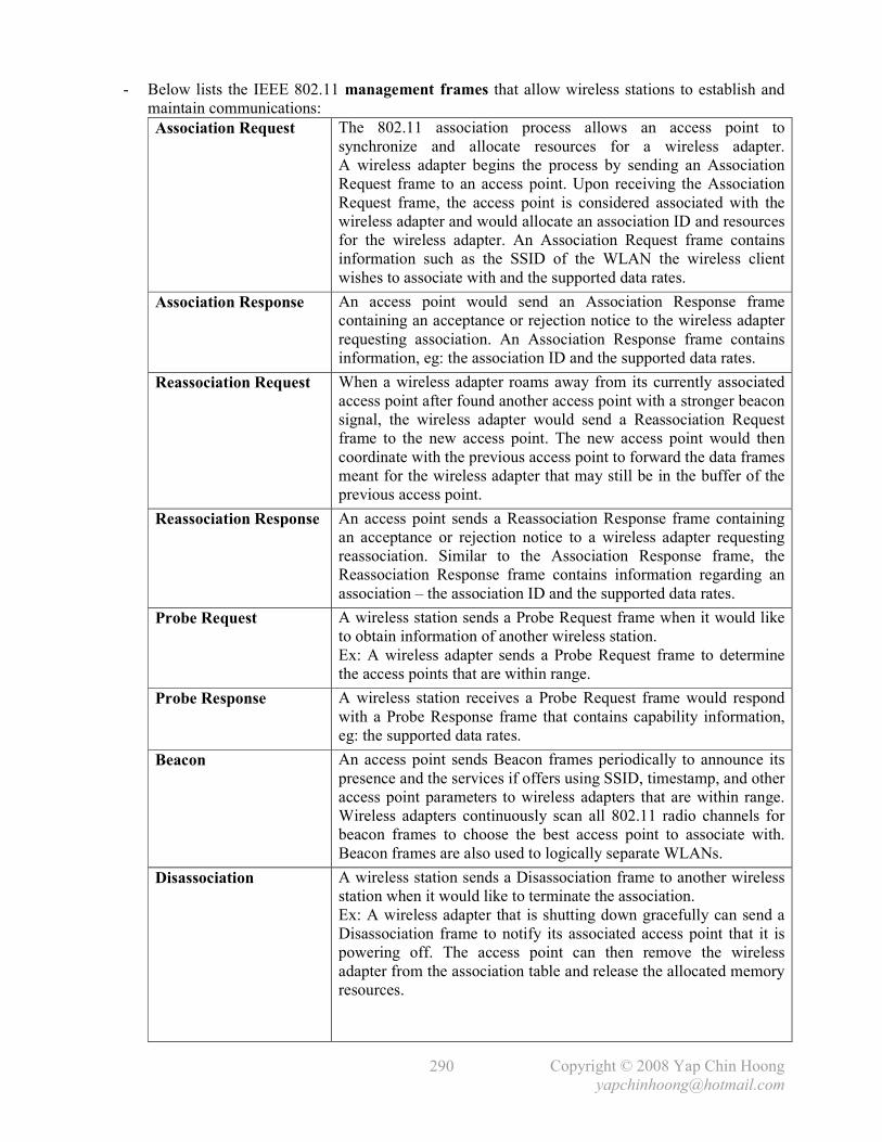
Copyright © 2008 Yap Chin Hoong
290
- Below lists the IEEE 802.11 management frames that allow wireless stations to establish and
maintain communications:
Association Request The 802.11 association process allows an access point to
synchronize and allocate resources for a wireless adapter.
A wireless adapter begins the process by sending an Association
Request frame to an access point. Upon receiving the Association
Request frame, the access point is considered associated with the
wireless adapter and would allocate an association ID and resources
for the wireless adapter. An Association Request frame contains
information such as the SSID of the WLAN the wireless client
wishes to associate with and the supported data rates.
Association Response An access point would send an Association Response frame
containing an acceptance or rejection notice to the wireless adapter
requesting association. An Association Response frame contains
information, eg: the association ID and the supported data rates.
Reassociation Request When a wireless adapter roams away from its currently associated
access point after found another access point with a stronger beacon
signal, the wireless adapter would send a Reassociation Request
frame to the new access point. The new access point would then
coordinate with the previous access point to forward the data frames
meant for the wireless adapter that may still be in the buffer of the
previous access point.
Reassociation Response An access point sends a Reassociation Response frame containing
an acceptance or rejection notice to a wireless adapter requesting
reassociation. Similar to the Association Response frame, the
Reassociation Response frame contains information regarding an
association – the association ID and the supported data rates.
Probe Request A wireless station sends a Probe Request frame when it would like
to obtain information of another wireless station.
Ex: A wireless adapter sends a Probe Request frame to determine
the access points that are within range.
Probe Response A wireless station receives a Probe Request frame would respond
with a Probe Response frame that contains capability information,
eg: the supported data rates.
Beacon An access point sends Beacon frames periodically to announce its
presence and the services if offers using SSID, timestamp, and other
access point parameters to wireless adapters that are within range.
Wireless adapters continuously scan all 802.11 radio channels for
beacon frames to choose the best access point to associate with.
Beacon frames are also used to logically separate WLANs.
Disassociation A wireless station sends a Disassociation frame to another wireless
station when it would like to terminate the association.
Ex: A wireless adapter that is shutting down gracefully can send a
Disassociation frame to notify its associated access point that it is
powering off. The access point can then remove the wireless
adapter from the association table and release the allocated memory
resources.

Copyright © 2008 Yap Chin Hoong
291
Authentication The 802.11 authentication process is where an access point accepts
or rejects the identity of a wireless adapter. A wireless adapter
begins the process by sending an Authentication frame that contains
its identity to the access point. For open authentication, the access
point responds with an Authentication frame as a response to
indicate the acceptance or rejection; while for shared-key
authentication, the access point responds with an Authentication
frame containing challenge text, which the wireless client must
response with an Authentication frame containing the encrypted
version of the challenge text using the shared-key for the access
point to verify its identity. WLAN authentication occurs at L2 and
is authenticating devices instead of users. The authentication and
association processes are occurred in sequence.
Note: Authentication occurs first and then followed by association.
Deauthentication A wireless station sends a Deauthentication frame to another
wireless station in order to terminate a secure connection.
- Below lists the IEEE 802.11 control frames that assist the delivery of data frames between
wireless stations:
Request to Send (RTS) A station sends a RTS frame to another station as the 1st phase of
the necessary 2-way handshake before transmitting a data frame.
Clear to Send (CTS) A station response to a RTS frame with the CTS frame to provide
the clearance for the source station to transmit a data frame.
The CTS frame contains a time value which would cause all
nearby stations (including hidden stations) to hold off data
transmission for a certain period of time necessary for the source
station to transmit its frames.
Acknowledgement (ACK) A destination station would run an error checking process to
detect the presence of errors upon received a data frame.
The destination station would send an ACK frame to the source
station if no errors are found. The source station will retransmit
the frame if it doesn’t receive an ACK for the frame for a certain
period of time.
Note: Kindly refer to Page 174 for the discussion of the CSMA/CA and RTS/CTS mechanisms.
- Finally, data frames are used to carry upper layers data – packets.
- Below shows the wireless client association process:
i) Access points send out beacons announcing the SSID and supported data rates.
ii) A wireless client scans all changes and sends out Probe Request frames to all access
points within range.
iii) All access points within range reply with a Probe Response frame, and the wireless client
listens for the responses from the access points.
iv) The wireless client associates with the access point with the strongest signal.
Authentication and other security information are sent to the access point.
v) The access point accepts the association request and associated with the wireless client.
Note: 802.1X authentication could occur straight after the association process is completed.
- The maximum Ethernet frame size is 1518 bytes whereas a wireless frame could be as large as
2346 bytes. Usually the WLAN frame size is limited to 1518 bytes as WLANs are often
connected to and communicating with wired Ethernet networks.

Copyright © 2008 Yap Chin Hoong
292
IEEE 802.11 Types and Subtypes
Type Value b3 b2
Type Description Subtype Value B7 b6 b5 b4
Subtype Description
00 Management 0000 Association Request 00 Management 0001 Association Response 00 Management 0010 Reassociation Request 00 Management 0011 Reassociation Response 00 Management 0100 Probe Request 00 Management 0101 Probe Response 00 Management 0110-0111 Reserved 00 Management 1000 Beacon 00 Management 1001 ATIM 00 Management 1010 Disassociation 00 Management 1011 Authentication 00 Management 1100 Deauthentication 00 Management 1101-1111 Reserved 01 Control 0000-1001 Reserved 01 Control 1010 PS-Poll 01 Control 1011 RTS 01 Control 1100 CTS 01 Control 1101 ACK 01 Control 1110 CF End 01 Control 1111 CF End + CF-ACK 10 Data 0000 Data 10 Data 0001 Data + CF-ACK 10 Data 0010 Data + CF-Poll 10 Data 0011 Data + CF-ACK + CF-Poll 10 Data 0100 Null function (no data) 10 Data 0101 CF-ACK (no data) 10 Data 0110 CF-Poll (no data) 10 Data 0111 CF-ACK + CF-Poll (no data) 10 Data 1000-1111 Reserved 11 Reserved 0000-1111 Reserved

Copyright © 2008 Yap Chin Hoong
293
IEEE 802.1X Port-Based Authentication
- The IEEE 802.1X standard defines a client-server-based access control and authentication
protocol that restricts unauthorized devices from gaining access to a network through publicly
accessible ports. The authentication server authenticates a client connects to a switch port before
granting the available network services to the client.
- 802.1X allows only Extensible Authentication Protocol over LAN (EAPOL) traffic through
the switch port which an unauthenticated client is connected to. Normal traffic can pass through
the switch port after authentication is completed successfully.
- With 802.1X port-based authentication, network devices have the following device roles:
Client
(Supplicant)
The device (workstation) that requires access to the LAN. Responds to the
requests from the switch. Must be running 802.1X-compliant client software.
Switch or
Access Point (Authenticator)
Controls the physical access to the network based on the authentication status
of the client. Acts as a proxy between the client and authentication server,
which requests identity information from the client, verify the information
with the authentication server, and relays the response to the client.
It is responsible for the re-encapsulation of the EAP and RADIUS frames
for communication with a client and an authentication server respectively.
Authentication
Server
Performs the authentication of the client. It validates the identity of the client
and notifies the switch or access point whether the client is authorized to
access the network. Currently, the RADIUS security system with EAP
extensions is the only supported authentication server.
Note: RADIUS is referred to as Remote Authentication Dial-In User Service.
Figure A6-21: The EAP Architecture
- EAP is designed to run over any link layer and use any number of authentication methods.

Copyright © 2008 Yap Chin Hoong
294
App06-22: 802.1X Authentication Message Exchange
- Below describes a typical WLAN 802.1X authentication process:
1) A wireless client becomes active on the medium. After the IEEE 802.11 WLAN
Probe Request/Response, Authentication, and Association processes, the access point
forces the port into an unauthorized state, which only 802.1X traffic is forwarded.
2) The access point replies with an EAP-Request Identity message to the wireless client to
obtain the client’s identity. The wireless client’s EAP-Response Identity message,
which contains the client’s identity, is forwarded to the authentication server.
3) The authentication server authenticates the wireless client and sends an Access Accept (or
Access Reject) message to the access point.
4) Upon receiving the Access Accept message, the access point relays the EAP-Success
message to the wireless client and transitions the client’s port to an authorized state and
normal traffic is forwarded.
- Note: Below lists the sequence of establishing WLAN connectivity with 802.1X authentication:
Probe Request, Probe Response, Authentication, Association, 802.1X authentication…
- When 802.1X is enabled, ports are authenticated before any other L2 or L3 features are enabled.
- Note: 802.1X is also considered as an efficient and effective alternative solution to port security.
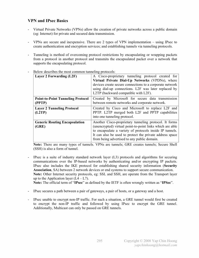
Copyright © 2008 Yap Chin Hoong
295
VPN and IPsec Basics
- Virtual Private Networks (VPNs) allow the creation of private networks across a public domain
(eg: Internet) for private and secured data transmission.
- VPNs are secure and inexpensive. There are 2 types of VPN implementation – using IPsec to
create authentication and encryption services; and establishing tunnels via tunneling protocols.
- Tunneling is method of overcoming protocol restrictions by encapsulating or wrapping packets
from a protocol in another protocol and transmits the encapsulated packet over a network that
supports the encapsulating protocol.
- Below describes the most common tunneling protocols:
Layer 2 Forwarding (L2F) A Cisco-proprietary tunneling protocol created for
Virtual Private Dial-Up Networks (VPDNs), where
devices create secure connections to a corporate network
using dial-up connections. L2F was later replaced by
L2TP (backward compatible with L2F).
Point-to-Point Tunneling Protocol
(PPTP)
Created by Microsoft for secure data transmission
between remote networks and corporate network.
Layer 2 Tunneling Protocol
(L2TP)
Created by Cisco and Microsoft to replace L2F and
PPTP. L2TP merged both L2F and PPTP capabilities
into one tunneling protocol.
Generic Routing Encapsulation
(GRE)
Another Cisco-proprietary tunneling protocol. It forms
(unencrypted) virtual point-to-point links which are able
to encapsulate a variety of protocols inside IP tunnels.
It can also be used to protect the private address space
from being advertised to any public domain.
Note: There are many types of tunnels. VPNs are tunnels; GRE creates tunnels; Secure Shell
(SSH) is also a form of tunnel.
- IPsec is a suite of industry standard network layer (L3) protocols and algorithms for securing
communications over the IP-based networks by authenticating and/or encrypting IP packets.
IPsec also includes the IKE protocol for establishing shared security information (Security
Association, SA) between 2 network devices or end systems to support secure communication.
Note: Other Internet security protocols, eg: SSL and SSH, are operate from the Transport layer
up to the Application layer (L4 – L7).
Note: The official term of “IPsec” as defined by the IETF is often wrongly written as “IPSec”.
- IPsec secures a path between a pair of gateways, a pair of hosts, or a gateway and a host.
- IPsec unable to encrypt non-IP traffic. For such a situation, a GRE tunnel would first be created
to encrypt the non-IP traffic and followed by using IPsec to encrypt the GRE tunnel.
Additionally, Multicast can only be passed on GRE tunnels.

Copyright © 2008 Yap Chin Hoong
296
- IPsec-based VPN is comprised of 2 parts – Internet Key Exchange (IKE) protocol and IPsec
security protocols – Authentication Header (AH) and Encapsulating Security Payload (ESP).
Below describes the flow of IPsec events:
i) IKE Phase 1: IKE Security Negotiation – IKE negotiates how to protect IKE by
establishing an authenticated and secure channel between 2 IKE peers called the
IKE Security Association. IKE Phase 1 is consists of Main Mode or Aggressive Mode.
The peer that initiates the session will propose or offer at least one or more configured
ISAKMP policies which specify a combination of encryption algorithm, hash algorithm,
authentication type, Diffie-Hellman group, and the lifetime. The remote peer will then try
to find a matching configured policy that has the same parameters as the one being sent
by its peer. If no matching policy is found, IKE will terminate the negotiation. If a policy
is mutually agreed upon, IKE will complete the negotiation process and an ISAKMP SA
will be created. Additionally, peers in an IPsec session must authenticate themselves
among each other during IKE Phase 1 Main Mode exchange before IKE can proceed.
ii) IKE Phase 2: IPsec Security Negotiation – IKE negotiates how to protect IPsec by
negotiating the IPsec security associations (SAs) and generating the keys for IPsec.
IKE Phase 2 negotiation is done in only 1 mode – Quick Mode. The peer that initiates
the session will propose or offer at least one or more configured transforms which specify
a combination of authentication and/or encryption algorithm. The remote peer will then
try to find a matching configured transform that has the same parameters as the one being
sent by its peer. If no matching transform is found, IKE will terminate negotiation and an
IPsec VPN will not be established. If a policy is mutually agreed upon, IKE will complete
the negotiation process and an IPsec SA will be created.
iii) IPsec transfers the actual data in the VPN tunnel using the authentication and encryption
methods agreed upon the IKE negotiation process.
- Internet Key Exchange (IKE) allows 2 VPN endpoints verify the identity of each other
(using pre-shared keys or RSA) in IKE Phase 1, and negotiate the methods (security policies) for
secured data transmission in IKE Phase 2. IKE manages VPN connections by defining a set of
Security Associations (SAs) for each connection. Each SA has its own SAID.
- In a VPN, before a communication path is considered secure, the VPN endpoints must be
authenticated. IPsec uses the following authentication methods to authenticate peers:
Pre-Shared Keys Secret key values that are manually configured on each peer.
RSA signatures Use the exchange of digital certificates to authenticate the peers.
- IKE is a hybrid protocol that uses part of Oakley and part of SKEME inside the ISAKMP
framework; hence IKE is formerly known as ISAKMP/Oakley. IKE typically uses ISAKMP for
key exchange and establishment of SAs, although other methods can be used.
- IKE establishes both ISAKMP and IPsec SAs for an IPsec VPN session. IKE first negotiates an
ISAKMP SA with the peer. It is possible to configure multiple policy statements with different
parameters, and then allow the peers to negotiate and establish a mutual agreement.
- An IPsec SA defines the security algorithms or parameters associated with particular connection
– the IPsec protocol (AH, ESP, or both), the session keys used for data encryption, etc.
IPsec SAs are unidirectional (simplex); hence there is always more than 1 IPsec SA per IPsec
connection. In cases where only either AH or ESP is used, 2 SAs will be created for each
connection – one for each the incoming and outgoing traffic. In cases where AH and ESP are
used in conjunction, 4 SAs will be created.

Copyright © 2008 Yap Chin Hoong
297
- The Internet Security Association and Key Management Protocol (ISAKMP) defines the
procedures for authenticating peers, IKASAMP and IPsec SAs establishment, negotiation,
modification, and deletion; key generation, and threat mitigation (eg: DoS and replay attacks).
- Instead of ISAKMP (the use of ipsec-isakmp keyword along with the crypto map global
configuration command), manual keying (the use of ipsec-manual keyword along with the
crypto map global configuration command) which require manual entry of the shared secret
session keys (used for hashing and encryption) on both crypto endpoints is also possible.
- IPsec operation requires both ends to be configured with the same transform set, which
specifies the methods for encrypt and decrypt the data. IPsec uses 2 primary security protocols –
Authentication Header (AH) and Encapsulating Security Payload (ESP). These protocols are
used for secured data transmission through an IPsec-based VPN tunnel. IPsec-based VPNs can
be established using AH only, ESP only, or both AH and ESP.
- The Authentication Header (AH) protocol provides authentication for both the IP header and
data of a packet using a one-way hash function. The sender first generates a one-way hash, and
then the receiver generates the same one-way hash. If the packet has changed in any way,
it won’t be authenticated and will be dropped. IPsec relies upon AH to guarantee authenticity.
AH provides integrity check on the entire packet, but it doesn’t provide any encryption services.
- ESP only provides integrity check (and encrypts) on the data of a packet (and the ESP header);
while AH checks the entire packet – both header and data. AH is used for authentication only,
while ESP can be used for either encryption or authentication only; or both.
- Although AH and ESP are typically used independently, they are often being used together to
provide data encryption service. Note: It is important to use authentication even if encryption is
used, as encrypt-only implementations are subject to some forms of effective attacks.
- ESP provides the following 4 functionalities or capabilities:
Confidentiality (Encryption) Provided through the use of symmetric encryption algorithms,
eg: DES, 3DES. Confidentiality can be selected separately
from all other services, but the confidentiality selected must be
the same on all VPN endpoints.
Data Origin Authentication
and Connectionless Integrity
Joint services offered as an option in conjunction with the
confidentiality option. Authentication ensures that the
connection is established with the desired system.
Anti-Replay Protection This service works only if data origin authentication is
selected. It is based upon the receiver – it is effective only if
the receiver checks the sequence number of the received
packets with a sliding window of the destination gateway or
host to prevent replay attacks.
Traffic Flow Confidentiality This service works only when tunnel mode is selected.
It is most effective if implemented at a security gateway,
where the source-destination patterns of attacks is visible.
- The degree of security of IPsec VPN is based on the encryption algorithm used and the length of
the pre-shared key. The longer the key, the harder it is to be broken.
- IPsec is not bound to any specific encryption or authentication algorithm, keying or technology,
or security algorithms, which allows IPsec to support newer and better algorithms.

Copyright © 2008 Yap Chin Hoong
298
- IPsec supports the following 3 types of encryption algorithms:
Data Encryption Standard (DES)
Uses a 56-bit key that ensures high performance encryption.
Uses a symmetric key cryptosystem.
Triple DES (3DES) A variant of DES that breaks data into 64-bit blocks. 3DES then
processes each block 3 times, each time with an independent 56-
bit key, hence providing significant improvement in encryption
strength over DES. Uses a symmetric key cryptosystem.
Advanced Encryption Standard (AES)
Provides stronger encryption than DES and is more efficient
than 3DES. Key lengths can be 128-, 192-, and 256-bit keys.
- Encryption algorithms (eg: DES, 3DES, and AES) require a symmetric shared secret key to
perform encryption and decryption. The Diffie-Hellman Key Exchange (D-H) is a public key
exchange process that allows 2 parties that have no prior knowledge of each other to negotiate
symmetric shared secret keys used for encryption and decryption over an insecure channel.
The shared secret keys are negotiated between crypto endpoints dynamically, which only the
prime modulus size for use in the D-H exchange is needed to be specified. IKE uses the D-H
keys to encrypt the ISAKMP SA when establishing the IPsec SAs. Additionally, D-H is also
used to generate shared secret keys to be used in the ciphers specified in the IPsec transforms,
which are then used in conjunction with the D-H keys by the IPsec to encrypt and decrypt the
data passes through the IPsec VPN tunnel.
- IPsec uses a data integrity algorithm called Hash-based Message Authentication Code
(HMAC) that adds a hash to the message to ensure data integrity. The hash guarantees the
integrity of the original message. If the transmitted hash matches the received hash, the message
is considered has not been tampered.
- IPsec uses the following 2 HMAC algorithms:
Message Digest Algorithm 5 (MD5)
Uses a 128-bit shared secret key. The message and 128-bit
shared secret key are combined and run through the MD5 hash
algorithm, producing a 128-bit hash. This hash is then added
to the original message and sent to the destination host.
Secure Hash Algorithm 1 (SHA-1)
Uses a 160-bit shared secret key. The message and 160-bit
shared secret key are combined and run through the SHA-1
hash algorithm, producing a 160-bit hash. This hash is then
added to the original message and sent to the destination host.
- Below lists the 2 modes of IPsec operation:
Transport Only the payload of the IP packet is encrypted and/or authenticated. The routing is
intact, as the IP header is neither modified nor encrypted. It is used for host-to-host
or end-to-end communications (end systems perform the security processing).
Tunnel The entire IP packet is encrypted and/or authenticated. The original packet is
encapsulated entirely into a new packet with a new set of source and destination IP
addresses for routing to work. It is used for network-to-network or portal-to-portal
communications (gateways or routers perform the security processing). It is the
traditional and default mode of IPsec VPNs.
- The Tunnel mode is most commonly used to secure existing IP traffic for communication
between end systems on networks connected to IPsec-enabled routers. With routers or VPN
endpoints performing the IPsec encryption, no changes are required to the software and drivers
on the end systems – the IPsec implementation is transparent to end systems.

Copyright © 2008 Yap Chin Hoong
299
Figure A6-23: IPsec in AH Transport Mode
Figure A6-24: IPsec in AH Tunnel Mode

Copyright © 2008 Yap Chin Hoong
300
Figure A6-25: IPsec in ESP Transport Mode
Figure A6-26: IPsec in ESP Tunnel Mode
- The main problem of IKE and IPsec protocols is NAT, as both protocols were not designed to
work through NAT. NAT Traversal (NAT-T) has evolved as a method of enabling IPsec-
protected IP packets to work well in NAT environments.

Copyright © 2008 Yap Chin Hoong
301
IPsec Configuration
Figure A6-27: Sample IPsec-Based VPN Network
- IPsec configuration on RT1:
- IPsec configuration starts with configuring the ISAKMP protection suite. The crypto isakmp
policy global configuration command first defines an ISAKMP policy. It is possible to define
multiple policies; the priorities of the policies determine the sequence of the policies during the
IKE negotiation phase (IKE Phase 1).
- The authentication pre-share ISAKMP subcommand tells IKE to use the manual key
configured with the crypto isakmp key global configuration command for authentication.
Note: The other 2 options beside the pre-share keyword are rsa-encr and rsa-sig, which
configures RSA Encryption and RSA Signature respectively. These keywords are used when
configuring ISAKMP using a CA (Certification Authority) instead of pre-shared keys.
Note: CA is a 3rd-party entity which is responsible for issuing and revoking digital certificates.
Each device that has its own certificate and public key of the CA can authenticate other devices
within a particular CA domain.
- The group {Diffie-Hellman group} ISAKMP subcommand defines the size of the modulus to
use for Diffie-Hellman calculation. Group 1 is 768-bit long, group 2 is 1024-bit long, and group
5 is 1536-bit long. The higher-number groups are significantly more CPU intensive but are more
secure than other lower-number groups. The default is group 1.
hostname RT1 ! crypto isakmp policy 1 encr 3des authentication pre-share group 2 crypto isakmp key CISCO-1234 address 10.10.10.2 ! ! crypto ipsec transform-set ESP-3DES-SHA esp-3des esp-sha-hmac ! crypto map CMAP-Site2 1 ipsec-isakmp description *** IPsec Tunnel to RT2 *** set peer 10.10.10.2 set transform-set ESP-3DES-SHA match address 102 ! interface Serial1/0 crypto map CMAP-Site2 ! access-list 102 permit ip 172.16.1.0 0.0.0.255 172.16.2.0 0.0.0.255 !

Copyright © 2008 Yap Chin Hoong
302
- It is possible to specify up to 6 transform sets for a particular crypto map and allow the peers to
negotiate a mutually agreed transform.
! crypto ipsec transform-set ESP-DES-MD5 esp-des esp-md5-hmac crypto ipsec transform-set ESP-3DES-SHA esp-3des esp-sha-hmac ! crypto map CMAP-Site2 1 ipsec-isakmp description *** IPsec Tunnel to RT2 *** set peer 10.10.10.2 set transform-set ESP-DES-MD5 ESP-3DES-SHA match address 102 ! _

Copyright © 2008 Yap Chin Hoong
303
Troubleshooting ISDN
Troubleshooting ISDN BRI Layer 1
- This section is only applicable to troubleshooting ISDN BRI Layer 1 deactivated status.
If the ISDN BRI Layer 1 is up and active as shown in the show isdn status EXEC command,
kindly proceed to Troubleshooting ISDN BRI Layer 2.
- Detailed information on ISDN Layer 1 states and signals are defined in the ITU-T I.430 standard.
- The show controller bri {num} EXEC command is used for advanced ISDN Layer 1
troubleshooting by displaying the information about the ISDN Layer 1 activation status.
- Use the following table to interpret the ISDN Layer 1 states:
L1 State L1 State Name L1 State Description F1 Inactive In this inactive (powered off) state, the terminal equipment (TE)
is not transmitting and cannot detect the presence of any input
signal.
F2 Sensing This state is entered after the TE has been powered on but has
not determined the type of signal (if any) that the TE is
receiving. When in this state, a TE may go into a lower power
consumption state.
F3 Deactivated This is the deactivated state of the physical protocol. Neither the
network termination (NT) nor the TE is transmitting. When in
this state, a TE may go to a low power consumption mode.
F4 Awaiting Signal When the TE wishes to initiate activation, it sends an Activation
signal to the NT and awaits a response.
F5 Identifying Input At the first receipt of any signal from the NT, the TE stops
sending Activation signals and awaits the activation signal or
synchronized frame from the NT.
F6 Synchronized When the TE has received an Activation signal from the NT, it
responds with a synchronized frame and is awaiting a
synchronized frame from the NT.
F7 Activated This is the normal active state, with the protocol activated in
both directions. Both the NT and the TE are transmitting normal
frames. State F7 is the only state where the B and D channels
contain operational data.
F8 Lost Framing This is the condition when the TE has lost frame
synchronization and is awaiting re-synchronization.
- Note: Most of the ISDN Layer 1 states are temporary and can be cleared with the clear
interface bri {num} privileged command or a router reboot. Contact the Telco for further
troubleshooting if those states persist for a long period.
Router>sh controllers bri0/0 BRI unit 0: Layer 1 is ACTIVATED. (ISDN L1 State F7) --- output omitted ---

Copyright © 2008 Yap Chin Hoong
304
Troubleshooting ISDN E1/T1 Physical Layer Alarms and Error Events
- This section explains the common alarm types and error events that may appear during the
operations of ISDN E1/T1 as well as the troubleshooting techniques.
- The show controller e1 | t1 {num} EXEC command displays the controller status specific to
the controller hardware, error statistics about the E1/T1 link, local or remote alarm information,
and information for identifying and troubleshooting ISDN physical and data link layer problems.
- Issue the show controller e1 | t1 {num} EXEC command repeatedly to see if the counters
for the frame loss, line code, and slip seconds errors and various alarms are increasing for a
particular duration of time, eg: 1 minute, 5 minutes.
- Below shows the sample output of the show controller e1 | t1 {num} EXEC command.
The output comprises of the alarm and error event sections.
- Contact the Telco for encoding and framing settings. HDB3 is the only defined encoding scheme
for E1 links, while CRC4 framing format is most widely used. Look for Clock Source is Line
in the output of the show controller e1 | t1 {num} EXEC command to verify that the
clocking is derived from the Telco.
Router>sh controller e1 E1 1/0 is up. Applique type is Channelized E1 - balanced No alarms detected. alarm-trigger is not set Framing is CRC4, Line Code is HDB3, Clock Source is Line. Module type is Channelized E1/T1 PRI Version info Firmware: 0000001D, FPGA: C Hardware revision is 0.0 , Software revision is 29 Protocol revision is 1 number of CLI resets is 16 Last clearing of alarm counters 1d22h receive remote alarm : 0, transmit remote alarm : 0, receive AIS alarm : 0, transmit AIS alarm : 0, loss of frame : 0, loss of signal : 0, Loopback test : 0, transmit AIS in TS 16 : 0, receive LOMF alarm : 0, transmit LOMF alarm : 0, MIB data updated every 10 seconds. Data in current interval (443 seconds elapsed): 0 Line Code Violations, 0 Path Code Violations 0 Slip Secs, 0 Fr Loss Secs, 0 Line Err Secs, 0 Degraded Mins 0 Errored Secs, 0 Bursty Err Secs, 0 Severely Err Secs, 0 Unavail Secs Total Data (last 24 hours) 0 Line Code Violations, 0 Path Code Violations, 0 Slip Secs, 0 Fr Loss Secs, 0 Line Err Secs, 0 Degraded Mins, 0 Errored Secs, 0 Bursty Err Secs, 0 Severely Err Secs, 0 Unavail Secs Router>

Copyright © 2008 Yap Chin Hoong
305
- Alarms are serious conditions that require attentions. Excessive errors, hardware problems, and
signal disruption can trigger alarms. The alarms are coded as colors. Different vendors define
alarm differently, and finding the details descriptions of the alarms can be challenging.
RFC 1232 describes most alarms; however, they are defined for use in SNMP and are not
intended to become a standard for hardware implementation.
- A Red Alarm is triggered when a Loss of Signal (LoS) or Loss of Frame (LoF) error is detected.
After a local device has a red alarm, it would send a yellow alarm to the far-end. When the far-
end receives the yellow alarm, it would trigger a yellow alarm.
Note: A red alarm is usually indicated on the opposite end of the yellow alarm, and vice versa.
- Loss of Signal (LoS) is the state where no electrical pulses have been detected – the line is dead,
there is no alarm and signal. LoS is equivalent to not connecting any cable to the interface.
Loss of Frame (LoF) indicates that a certain number of frames have been received with framing
bits in error. The data is considered garbage as the synchronization between both ends is invalid.
- A sample scenario of red alarm is when something has failed on an ISDN switch, the switch
would trigger a local red alarm and sends out yellow alarm signal to alert the neighboring router
regarding the problem. Another sample scenario is when an ISDN switch is sending garbled
frame to the neighboring router, which sees consecutive LoF errors and declares a red alarm.
When the router declares a red alarm, a yellow alarm is sent back out across the link.
- Interpreting the behaviors of red alarms can be challenging and confusing. Generally, a red alarm
indicates that there is a problem happening on the local device. However, the router in the 2nd
scenario above was receiving too much LoF errors until it is unable to recognize the signals and
frames from the ISDN switch.
- A Yellow Alarm is also known as a Remote Alarm Indication (RAI). A yellow alarm is
declared when a yellow alarm signal is received from the far-end. A yellow alarm does not
necessarily indicate a problem on the local device; rather there is a problem at the far-end device,
which has declared a red alarm and notifies the local device. Generally, a yellow alarm indicates
that the far-end receiver is in a LoS or LoF state. When the receiver experiences LoS or LoF, the
transmitter sends a yellow alarm. The circuit is considered as a one-way link – the transmitting
line towards the far-end device is experiencing problem while the transmitting line towards the
local device is functioning as it is able to receive the Yellow Alarm signal.
Note: A yellow alarm is usually indicated on the opposite end of the red alarm, and vice versa.
- A Blue Alarm is also known as an Alarm Indication Signal (AIS). RFC 1232 does not define
about this condition. A blue alarm is triggered when the receiver receives an AIS. Generally, a
blue alarm indicates that there is a problem upstream. An AIS in a framed or unframed all-1s
signal which is transmitted to maintain transmission continuity. It typically occurs when the far-
end CSU has lost its terminal side equipment or a cable is disconnected.
- The blue alarm is often sent from the service provider to both ends of the circuit to notify them
that there is a problem within the service provider’s network.

Copyright © 2008 Yap Chin Hoong
306
- Below addresses ISDN E1/T1 controller alarms along with the procedures to correct them:
Receive Alarm Indication Signal
(rxAIS)
Indicates that a stream of framed or unframed all-1s
signal is received. This problem should be cleared
when the LoF error is rectified. Change the framing
format with the framing {esf | sf | crc4 | no-crc4}
interface subcommand.
Receive Remote Alarm Indication
(rxRAI)
Indicates that the far-end device has a problem with
the signal which is receiving from the local device.
Perform hard plug loopback tests to verify the ISDN
controller hardware is OK. Check or replace cables to
isolate cabling problems.
Transmit Remote Alarm Indication
(txRAI)
Indicates that the ISDN interface has a problem with
the signal it receives from the far-end equipment.
Check the settings at the remote end to ensure that they
match the local port settings.
Transmit Alarm Indication Signal
(txAIS)
Indicates that the ISDN controller is shut down. Issue
the show controller e1 | t1 {num} EXEC
command to verify that the ISDN controller is up. If
the ISDN controller is down, issue the no shutdown
interface subcommand to bring it up.
- Below describes the various error events that occur on ISDN E1/T1 lines along with the
troubleshooting guidelines for them:
Linecode Violations Indicates that either a Bipolar Violation (BPV) or excessive zero
error event is present. BPVs are inserted upon the synchronization
of circuits with B8ZS linecoding. Linecode errors occur when
BPVs that are used for synchronization are received. Excessive
zero errors occur when 8 or more 0s in sequence are received on
circuits with AMI linecoding. These errors normally occur due to
an AMI/B8ZS linecoding misconfiguration on the intermediate
devices along the transmission path.
Pathcode Violations Examples are frame synchronization errors for SF and cyclic
redundancy check (CRC) errors for ESF. Both linecode and
pathcode violations are often present at the same time; hence
always verify the linecoding configuration. Note that some errors
can occur due to impulse noise, in which the errors might appear
only a few times a day and the impact or interrupt is minimal.
Slip Seconds Indicates a clocking problem. The ISDN network would provide
the clocking in which the CPE must synchronize. Look for Clock
Source is Line in the output of the show controller e1 | t1
{num} EXEC command to verify that the clocking is derived
from the Telco.
Loss of Frame Triggered when the receiver detects multiple framing-bit errors.
The data is considered garbage as the synchronization between
both ends is invalid. When this state is triggered, the framer starts
searching for a correct framing pattern. The LoS state ends when
reframe occurs. Ensure the framing format is configured correctly.
Change the framing format with the framing {esf | sf | crc4 |
no-crc4} interface subcommand.

Copyright © 2008 Yap Chin Hoong
307
Loss of Signal Triggered upon observing 175 +/- 75 contiguous pulse positions
with no pulses of either positive or negative polarity for T1 lines;
or when more than 10 consecutive 0s are detected for E1 lines.
Code Violation Error The CRC value in the received frame does not match with the
corresponding locally calculated CRC value.
Bipolar Violation Occurs when 2 mark signals (1s) occur in sequence with the same
polarity (when not part of a B8ZS substitution). T1 signaling
specifies that each mark must be the opposite polarity of the one
preceding it. It also includes other error patterns such as 8 or more
consecutive 0s and incorrect parity.
Errored Second A second with one or more Code Violation Error or Loss of
Frame events have occurred. The presence of Bipolar Violations
also triggers an Errored Second. Some errored seconds may occur
on a normal circuit.
Severely Errored Second A second with 320 or more Code Violation Error or Loss of
Frame events have occurred. Also known as Extreme Errored
Second (EES).
Unavailable Second A second that the CSU is in the Unavailable Signal state,
including the initial 10 seconds to enter the state, but excluding
the 10 seconds to exit the state.

Copyright © 2008 Yap Chin Hoong
308
Troubleshooting ISDN Layer 2
- Understanding the output messages of the debug isdn q921 command is vital in
troubleshooting ISDN Layer 2 Firstly, issue the debug isdn q921 to enable the ISDN Layer 2
debugging which provides the details of ISDN Layer 2 transactions between the router and the
Telco ISDN switch. Subsequently, issue the clear interface bri {num} or clear interface
serial {num:15} privileged command to reset the ISDN interface which forces the router to
renegotiate ISDN Layer 2 information with the Telco ISDN switch.
- Below shows the sample output messages of the debug isdn q921 command:
Router#debug isdn q921 debug isdn q921 is ON. Router#
Router#sh isdn status Global ISDN Switchtype = basic-net3 ISDN BRI0/0 interface dsl 0, interface ISDN Switchtype = basic-net3 Layer 1 Status: ACTIVE Layer 2 Status: TEI = 76, Ces = 1, SAPI = 0, State = TEI_ASSIGNED Layer 3 Status: 0 Active Layer 3 Call(s) Active dsl 0 CCBs = 0 The Free Channel Mask: 0x80000003 Total Allocated ISDN CCBs = 0 Router#
Router#clear int bri0/0 Router# 23:20:28: ISDN BR0/0 Q921: User TX -> IDREQ ri=24872 ai=127 23:20:28: ISDN BR0/0 Q921: User RX <- IDASSN ri=24872 ai=75 23:20:28: ISDN BR0/0 Q921: L2_EstablishDataLink: sending SABME 23:20:28: ISDN BR0/0 Q921: User TX -> SABMEp sapi=0 tei=75 23:20:28: ISDN BR0/0 Q921: User RX <- UAf sapi=0 tei=75 23:20:28: %ISDN-6-LAYER2UP: Layer 2 for Interface BR0/0, TEI 75 changed to up 23:20:38: ISDN BR0/0 Q921: User RX <- RRp sapi=0 tei=75 nr=0 23:20:38: ISDN BR0/0 Q921: User TX -> RRf sapi=0 t Total Allocated ISDN CCBs = 0 23:20:48: ISDN BR0/0 Q921: User RX <- RRp sapi=0 tei=75 nr=0 23:20:48: ISDN BR0/0 Q921: User TX -> RRp sapi=0 tei=75 nr=0 23:20:48: ISDN BR0/0 Q921: User TX -> RRf sapi=0 tei=75 nr=0 23:20:48: ISDN BR0/0 Q921: User RX <- RRf sapi=0 tei=75 nr=0 Router#
Router#sh isdn status Global ISDN Switchtype = basic-net3 ISDN BRI0/0 interface dsl 0, interface ISDN Switchtype = basic-net3 Layer 1 Status: ACTIVE Layer 2 Status: TEI = 75, Ces = 1, SAPI = 0, State = MULTIPLE_FRAME_ESTABLISHED Layer 3 Status: 0 Active Layer 3 Call(s) Active dsl 0 CCBs = 0 The Free Channel Mask: 0x80000003 Total Allocated ISDN CCBs = 0 Router#

Copyright © 2008 Yap Chin Hoong
309
IDREQ Identity Request transmitted from the router to the ISDN switch requesting a
Terminal Endpoint Identifier (TEI). All IDREQ messages have an AI value of 127
which indicates that the ISDN switch can assign any available TEI value.
IDASSN Identity Assigned message with the TEI value of 75 assigned by ISDN switch is
received from the ISDN switch.
SABMEp Request the connection to be in Multiple Frame Established state.
SABME � Asynchronous Balanced Mode Extended.
UAf Unnumbered Acknowledgment (UA) of the SABME message. The ISDN Layer 2 is
now in Multiple Frame Established state.
- An operational and functioning ISDN circuit (Multiple Frame Established) should have periodic
exchanges of RRp sapi = 0 and RRf sapi = 0 messages between the router and ISDN switch.
The interval between Receiver Ready poll (RRp) and Receiver Ready final (RRf) messages is
usually 10 or 30 seconds.
Note: TX -> indicates that a message is generated by the router while RX <- indicates that a
message is received by the router.
- Below shows the debug isdn q921 messages originated from the ISDN switch which indicate
various ISDN Layer 2 problems:
Message Explanation ID-Denied The ISDN switch cannot assign the requested TEI. If this message has an AI value
of 127, it indicates that the ISDN switch has no TEI available.
IDREM The ISDN switch has removed the TEI from the connection. The router must
terminate all existing communication using the particular TEI.
DISC The sending side of the DISConnect message has terminated the operation of
ISDN Layer 3 for the connection. It may be unnumbered acknowledged by the
other side. The router should then send a SABME message to reestablish the link.
DM Indicates the Acknowledged Disconnect mode. The ISDN switch does not wish to
enter the Multiple Frame Established state, and hence the router will remain in
Layer 2 TEI_ASSIGNED state. The router will continuously send SABME
messages until the ISDN switch responds with a UA instead of DM.
FRMR The Frame Reject Response indicates an error that cannot be recovered by
retransmission. The router will initiate a Layer 2 reset and transmit a SABME
message to request to enter into Multiple Frame Established state.
--- output omitted --- 23:23:05: ISDN BR0/0 Q921: User RX <- DISCp sapi=0 tei=75 23:23:05: %ISDN-6-LAYER2DOWN: Layer 2 for Interface BR0/0, TEI 75 changed to down 23:23:05: ISDN BR0/0 Q921: User TX -> UAf sapi=0 tei=75
Router#sh isdn status Global ISDN Switchtype = basic-net3 ISDN BRI0/0 interface dsl 0, interface ISDN Switchtype = basic-net3 Layer 1 Status: ACTIVE Layer 2 Status: TEI = 75, Ces = 1, SAPI = 0, State = TEI_ASSIGNED Layer 3 Status: 0 Active Layer 3 Call(s) Active dsl 0 CCBs = 0 The Free Channel Mask: 0x80000003
Total Allocated ISDN CCBs = 0

Copyright © 2008 Yap Chin Hoong
310
Troubleshooting ISDN Layer 3
- Only proceed to this section after ISDN Layers 1 and 2 on both ends of a circuit are verified OK.
- ISDN call failures could be due to any of the following:
i) Dial-on-Demand Routing (DDR) related issues.
ii) ISDN Layer 1, 2, or 3 problems.
iii) Point-to-Point Protocol (PPP), including authentication, Link Control Protocol (LCP), or
IP Control Protocol (IPCP) related issues.
- Figure A6-28 illustrates common Q.931 transactions during a successful ISDN call setup.
Figure A6-28: ISDN Call Setup Sequence
- Pay attention to the direction of the output messages from the debug isdn q931 privileged
command. The TX -> indicates that a message is generated by the router while the RX <-
indicates that a message is received by the router.
- The source of a problem can be identified by following the direction of a particular message and
the response. Ex: If the local router unexpectedly receives a RELEASE message from the ISDN
switch, then it will reset its end of the call as well. This indicates that there is an issue in the
ISDN switch or the remote router.
- Verify that the message received or sent is the expected one. Ex: If the called party receives a
SETUP message but responses with a DISCONNET message instead of a CONNECT message,
then troubleshoot the called router and not the ISDN network.

Copyright © 2008 Yap Chin Hoong
311
- Below lists all the possible Q.931 messages during call establishment and termination:
Message Description
SETUP Indicates that a device would like to establish an ISDN Layer 3 call.
CALL_PROC The SETUP message is received and is being processed by the network
and/or the remote device.
ALERTING Informs the network that the router is alerting the user, which would
normally be the case for a telephone and the alert would ring the handset.
This message is normally associated with equipment using a handset, eg:
an ISDN telephone or TA and is not usually seen for data calls.
CONNECT Call is accepted.
CONNECT_ACK Connect Acknowledge. The device has received the CONNECT
message. Higher layer protocols (eg: PPP) should now begin the
negotiation process.
DISCONNECT The router initiated a DISCONNECT message, which usually indicates
that an operational ISDN call is disconnected due to some higher layer
issues (eg: DDR, PPP, etc). The 3-way Disconnect Handshake will be
accompanied by a RELEASE message, a Disconnect Cause Code, and a
RELEASE_COMP message.
RELEASE Acknowledges the DISCONNECT message and continues the circuit
termination process. The RELEASE message is sent between the
DISCONNECT and RELEASE_COMP messages.
RELEASE_COMP Release Complete. The call termination is completed. This message is
often seen during a normal call termination initiated by one of the
routers; in response to a SETUP message from the calling party when
there is a mismatch of bearer capability between the ISDN switch and the
router; or due to protocol error if the coding of the SETUP message does
not comply with the Q.931 standard or the configuration of the ISDN
switch.
- If the calling router does not send a SETUP message to the ISDN switch, the problem is likely
related to ISDN Layer 1, 2, or DDR issues, and is not ISDN Layer 3 related. Perform the
following troubleshooting tasks on the calling and called routers:
i) Verify that the ISDN switch types on both routers are configured correctly.
ii) Verify that the ISDN Layers 1 and 2 on both routers are functioning.
iii) Perform ISDN loopback test calls on both routers to verify they are able to initiate and
accept calls.
iv) Verify the ISDN network of the called side is functioning by making a test call to the
called router with a regular analog phone, in which the router should receive a SETUP
message, although the call would eventually fail as it is not an ISDN call.
v) Verify that the calling router has a route to the destination with the show ip route
EXEC command.
vi) Verify that the interesting traffic on the calling router is identified correctly.
vii) Verify that the appropriate dialer string or dialer map interface subcommand on the
calling router refers to the correct number to the called router.
viii) Check the DDR configuration and use the debug dialer privileged command to verify
that the calling router is able to initiate calls.
ix) If the called router does not send a CONNECT message, check if the call is rejected due
to the misconfiguration of the isdn caller {incoming-number} interface subcommand.
x) Contact the Telco and determine whether the long distance call service is activated.
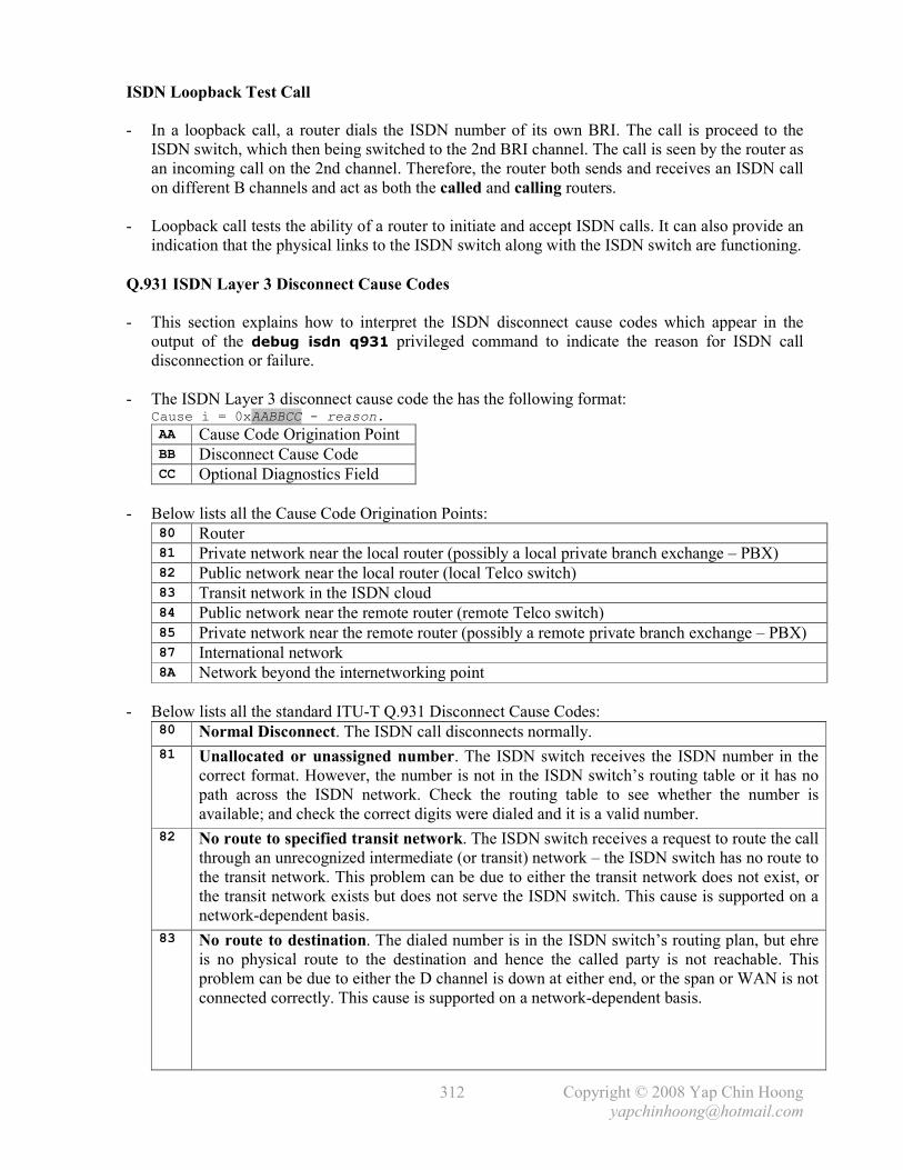
Copyright © 2008 Yap Chin Hoong
312
ISDN Loopback Test Call
- In a loopback call, a router dials the ISDN number of its own BRI. The call is proceed to the
ISDN switch, which then being switched to the 2nd BRI channel. The call is seen by the router as
an incoming call on the 2nd channel. Therefore, the router both sends and receives an ISDN call
on different B channels and act as both the called and calling routers.
- Loopback call tests the ability of a router to initiate and accept ISDN calls. It can also provide an
indication that the physical links to the ISDN switch along with the ISDN switch are functioning.
Q.931 ISDN Layer 3 Disconnect Cause Codes
- This section explains how to interpret the ISDN disconnect cause codes which appear in the
output of the debug isdn q931 privileged command to indicate the reason for ISDN call
disconnection or failure.
- The ISDN Layer 3 disconnect cause code the has the following format: Cause i = 0xAABBCC - reason.
AA Cause Code Origination Point BB Disconnect Cause Code CC Optional Diagnostics Field
- Below lists all the Cause Code Origination Points: 80 Router 81 Private network near the local router (possibly a local private branch exchange – PBX) 82 Public network near the local router (local Telco switch) 83 Transit network in the ISDN cloud 84 Public network near the remote router (remote Telco switch) 85 Private network near the remote router (possibly a remote private branch exchange – PBX) 87 International network 8A Network beyond the internetworking point
- Below lists all the standard ITU-T Q.931 Disconnect Cause Codes: 80 Normal Disconnect. The ISDN call disconnects normally.
81 Unallocated or unassigned number. The ISDN switch receives the ISDN number in the
correct format. However, the number is not in the ISDN switch’s routing table or it has no
path across the ISDN network. Check the routing table to see whether the number is
available; and check the correct digits were dialed and it is a valid number.
82 No route to specified transit network. The ISDN switch receives a request to route the call
through an unrecognized intermediate (or transit) network – the ISDN switch has no route to
the transit network. This problem can be due to either the transit network does not exist, or
the transit network exists but does not serve the ISDN switch. This cause is supported on a
network-dependent basis.
83 No route to destination. The dialed number is in the ISDN switch’s routing plan, but ehre
is no physical route to the destination and hence the called party is not reachable. This
problem can be due to either the D channel is down at either end, or the span or WAN is not
connected correctly. This cause is supported on a network-dependent basis.

Copyright © 2008 Yap Chin Hoong
313
84 Send special information tone. The called party is not reachable and a special information
tone should be returned from the calling party. Check the dialing number and verify whether
any prefix is required to access the network, eg: a 9 might need to be dialed for outbound
calls through a PBX. Contact the Telco or PBX administrator for details.
85 Misdialed trunk prefix. There is erroneous inclusion of a trunk prefix in the dialed number.
Check the dialing number and verify whether any prefix is required to access the network,
eg: a 9 might need to be dialed for outbound calls through a PBX. Contact the Telco or PBX
administrator for details.
86 Channel unacceptable. The service quality of the specified channel is insufficient to accept
the connection. The call fails due to the channel is not acceptable (unusable) for the call.
If a PBX is in used, check the configuration of the PBX. If a PRI is in used, find out how
many channels are provided by the Telco.
87 Call awarded and being delivered in an established channel. The called party receives an
incoming call, but the call is being connected to a channel already established for similar
calls (eg: packet-mode virtual calls).
88 Preemption. The call is being preempted or blocked. Sometimes calls are blocked if
another call has a higher priority than the current call, which is common with voice calls.
Wait and call again later. If a local or remote PBX is in used, check the configuration of the
PBX. Contact the Telco if the problem persists.
89 Preemption, circuit reserved for re-use. The call is being cleared as one of the routers
involved in the call has requested to terminate and clear the call.
90 Normal call clearing. The call disconnects and normal call clearing occurs due to one of
the routers involved in the call requested to terminate and clear the call. This is one of the
most common cause codes and is received for many reasons. Most of the time, the ISDN
network is not the source of this cause. If a call fails with this cause, it is most likely fails
with a higher layer protocol, eg: PPP, authentication, or idle timeout related issues.
Verify the router configuration to resolve such problems. Additionally, if callback is
configured on the local router, the remote router will disconnect the calls, generates this
code, and calls the local router back.
91 User busy. The called party acknowledges the connection request. However, it is unable to
accept the call due to all B channels are in use (the dialed number is busy). The routers are
compatible with the call in this situation. Note: If there are multiple ISDN circuits, the
Telco can configure them in a hunt-group, which calls are switched to next available circuit.
92 No user response. The called party does not respond to the call establishment message
within a prescribed duration, or it does not wish to answer the call. The called party must
respond with either an alert or connect indication according to ITU-T Q.931, when either
timer T303 or T310 expires.
93 No answer from user. The called party is alerted to the connection request but does not
respond with a connect indication to establish the connection within a prescribed duration.
This cause is not necessary generated by Q.931 procedures; it may be generated by internal
network timers. The problem is at the remote router.
94 Subscriber absent. The remote router is unavailable or disconnected from the ISDN
network. Contact the person responsible for the remote router.
95 Call rejected. The remote router rejects the call due to an unknown reason. Note: The
remote router is able to accept the call as it is able to respond with this cause, it is neither
busy nor incompatible. This cause may also be generated by the ISDN network indicating
that the call was cleared due to a supplementary service constraint.

Copyright © 2008 Yap Chin Hoong
314
96 Number changed. The called number is no longer assigned to any device. The new called
number may optionally be included in the diagnostic field. If the network does not support
this cause, the caller receives disconnect cause code 81 – unallocated or unassigned number.
97 Redirection to new destination. The call is routed to a different number. Check the called
number and verify the configuration of the PBX if PBX is in used.
99 Exchange routing error. The call cannot be successfully routed to the remote router.
Check the called number and verify the configuration of the PBX if a PBX is in used.
9A Non-selected user clearing. The remote router is able to accept the call. However, it rejects
the call due to the call is not assigned to any user.
9B Destination out of order. The remote router is not reachable as there is a problem sending
the signaling message to the remote router. This condition is often temporary, but can also
last for an extended period in some cases. Possible causes are ISDN layer 1 or 2 fails at the
remote end, or the remote router is powered off.
9C Invalid number format. The call fails due to the called number is not in a valid format or is
incomplete. This can also happen when the local router calling out using network-specific
ISDN Type of Number (TON) when it should be calling out using National or Unknown for
the ISDN Type of Number (TON). Verify whether the format of the number is correct,
which includes any necessary digits for a PBX or long distance.
9D Facility rejected. The ISDN network is unable to provide a requested supplementary service.
9E Response to STATUS ENQUIRY. This cause code is included in a STATUS message
when the STATUS message is generated upon the receipt of a STATUS ENQUIRY message.
9F Normal, unspecified. This is a very common cause code and happens when the network is
not able to determine the next course of action for the call. No action is required.
A1 Circuit out of order. The call fails due to some problems in the ISDN network.
A2 No channel available. The call fails due to no B channel is available to answer the call.
A3 Destination unattainable. The destination is not reachable through the ISDN network.
Contact the Telco.
A4 Out of order. Some parts of the ISDN network necessary to route the call is out of order.
The destination is not reachable due to a network malfunction. This condition can last for a
relatively long period. An immediate attempt to reconnect will probably fail. Try to use a
Presubscribed Inter-exchange Carrier (PIC) if a long distance carrier is being used. A PIC
allows us to verify whether the problem lies with the long distance carrier.
A6 Network out of order. The destination is not reachable due to a network malfunction.
This condition can last for a relatively long period. An immediate attempt to reconnect will
probably fail. Try to use a Presubscribed Inter-exchange Carrier (PIC) if a long distance
carrier is being used. A PIC allows us to verify whether the problem lies with the long
distance carrier.
A7 Permanent frame mode connection out of service. This cause code is included in a
STATUS message to indicate that a permanently established frame mode connection is
terminated. Contact the Telco if the problem persists.
A8 Permanent frame mode connection operational. This cause code is included in a
STATUS message to indicate that a permanently established frame mode connection is fully
operational again and capable of carrying user information after a termination.
The connection is probably terminated by a faulty equipment previously.
A9 Temporary failure. The call is disconnected due to a network malfunction. This condition
is not likely to last a long period of time; another call attempt can be tried immediately.
Contact the Telco if the problem persists.

Copyright © 2008 Yap Chin Hoong
315
AA Switching equipment congestion. The destination is unreachable due to a temporary high
traffic load on the network switching equipment. Try again later.
AB Access information discarded. The ISDN network is unable to provide the requested
access information. Note: The diagnostics field may indicate the particular type of discarded
access information, eg: user-to-user information, low layer compatibility, high layer
compatibility, and sub-address.
AC Requested channel not available. The remote router is unable to provide the requested
channel due to an unknown reason. This may happen when there is a glare condition, in
which both sides are selected top-down or bottom-up channel hunting. This problem is
usually temporary.
AF Resources unavailable, unspecified. This cause code is used to report a resource
unavailable event only when no other cause in the resource unavailable class applies.
This problem is usually temporary.
B1 Quality of server (QoS) unavailable. The ISDN network unable to provide the requested
Quality of Service as defined in Recommendation X.213. This problem can occur due to a
subscription problem, or the ISDN network does not support throughput or transit delay.
B2 Requested facility not subscribed. The local router is not authorized to use a requested
supplementary service which is implemented by the ISDN switch. The administrator has
probably not completed the necessary administrative arrangements with the service provider.
The ISDN network can also return this cause code if a call is made without supplying the
SPIDs, or the SPIDs are entered wrongly. Ensure that the SPIDs are correct, or contact the
Telco for verification.
B4 Outgoing calls barred. There are some restrictions on outgoing calls. The ISDN network
does not allow the local router to make outgoing calls.
B5 Outgoing calls barred within CUG. There are some restrictions on outgoing calls. The
ISDN network does not allow the local router to make outgoing calls although the calling
party is a member of the CUG for the outgoing CUG call. Outgoing calls are not allowed for
this member of the CUG. Contact the Telco.
B6 Incoming calls barred. The ISDN network does not allow the local router to receive calls.
Contact the Telco.
B7 Incoming calls barred within CUG. The ISDN network does not allow the local router to
receive calls although the called party is a member of the CUG for the incoming CUG call.
Incoming calls are not allowed for this member of the CUG. Contact the Telco. B9 Bearer capability not authorized. The local router requests a bearer capability that the
ISDN switch implements, however the local router is not authorized to use the capability.
A subscription problem usually causes this problem.
BA Bearer capability not presently available. The ISDN network normally provides the
requested bearer capability. However, the capability is unavailable at the particular moment.
Normally caused by a temporary ISDN network problem or a subscription problem.
BE Inconsistency in designated outgoing access information and subscriber class. There is
an inconsistency in the designated outgoing access information and subscriber class.
BF Service or option not available, unspecified. This cause code is used to report a service or
option is unavailable event only when no other cause in the service or option not available
class applies. Normally caused by a subscription problem.
C1 Bearer capability not implemented. The ISDN network is unable to provide the requested
bearer capability, eg: requesting 64kb data when only speech is supported. Contact the
Telco for further troubleshooting.

Copyright © 2008 Yap Chin Hoong
316
C2 Channel type not implemented. The equipment sending this cause does not support the
requested channel type.
C5 Requested facility not implemented. The equipment sending this cause does not support
the requested supplementary service.
C6 Only restricted digital info bearer capability available. The equipment sending this cause
does not support and hence unable to provide unrestricted digital information bearer service
(64kb). It only supports the restricted version of the requested bearer capability.
CF Service or option not implemented, unspecified. This cause code is used to report a
service or option not implemented event only when no other cause in the service or option
not implemented class applies. Normally caused by a subscription problem.
D1 Invalid call reference value. The equipment sending this cause receives a call with a call
reference that is not currently in use or assigned on the user-network interface.
Ex: The call that is being referenced by the call reference value does not exist on the system.
D2 Identified channel does not exist. The equipment sending this cause receives a request to
use an inactive channel for a call. Ex: When a PRI is subscribed to use channels 1 to 12 and
the router or the ISDN network attempts to assign a call to channels 13 to 25.
D3 Suspended call exists, but call id does not. The ISDN switch receives a call resume
request which contains a Call Identify (ID) information element that differs from the ID in
use for any currently suspended call.
D4 Call id in use. The ISDN switch receives a call suspend request which contains a call ID
that is already in use for a suspended call which the call can be resumed instead of
suspended again.
D5 No call suspended. The ISDN switch receives a call resume request when there is no
currently suspended call. This transient error can be resolved through successive call retries.
D6 Call with requested call id has been cleared. The ISDN switch receives a call resume
request which contains a call ID that indicates a suspended call. However, either a network
timeout or the remote router has cleared the call while the call was suspended.
D7 User not member of CUG. The called party for the incoming CUG call is not a member of
the specified CUG; or the calling party is an ordinary subscriber calling a CUG subscriber.
D8 Incompatible destination. Indicates an attempt to connect to non-ISDN device (eg: an
analog line), in which the equipment sending this cause is not capable of answering a
particular type of call – it is unable to accommodate a low layer compatibility, high layer
compatibility, or other compatibility attributes. This cause code often appears when the
calling device dials a wrong number and reaches a non-ISDN device; a data call is made to a
voice number; a voice call is made to a number that only supports data; calling a restricted
line in unrestricted mode; or calling a POTS phone using unrestricted mode. Check that the
correct number is dialed. If the dialed number is correct, contact the Telco to verify that the
ISDN switch configuration.
DA Non-existent CUG. The specified CUG does not exist. Contact the Telco if the problem
persists.
DB Invalid transit network selection. The ISDN switch is requested to route the call through
an unrecognized intermediate network – it receives a transit network identification which is
in an incorrect format as defined in Annex C of ITU-T Q.931.
DF Invalid message, unspecified. This cause code is used to report an invalid message event
only when no other cause in the invalid message class applies. This problem usually occurs
due to a D channel error. Contact the Telco if the problem occurs systematically.

Copyright © 2008 Yap Chin Hoong
317
E0 Mandatory IE missing. The equipment sending this cause receives a message is missing an
information element that is necessary for it to process the message. This problem usually
occurs due to a D channel error. Upgrade the Cisco IOS software on the router to resolve
this problem. Contact the Telco if the problem occurs systematically.
E1 Message type not implemented. The equipment sending this cause receives an
unrecognized message due to either the message type is invalid, or it does not support or
implement the message type. The problem usually occurs due to the D channel of the local
router or the configuration of the remote router.
E2 Message not compatible with call state or not implemented. The equipment sending this
cause receives a message that is not permissible in the call state according to the procedures,
or it receives a STATUS message which indicates an incompatible call state. This problem
usually occurs due to a D channel error. Contact the Telco if the problem occurs.
E3 IE not implemented. The equipment sending this cause receives a message that contains an
unrecognized information element which it does not support or implement. However, the
message does not need to contain the information element in order for the equipment
sending this cause to process the message. This problem usually occurs due to a D channel
error. Contact the Telco if the problem occurs.
E4 Invalid IE contents. The ISDN switch receives a message that contains invalid contents in
the information element – the information element is implemented, but one or more of the
fields in the information element are coded differently. This cause is usually followed by the
information element that is causing the problem.
E5 Message not compatible with call state. The ISDN switch receives a message that does not
correspond to the current call state for the call.
E6 Recovery on timer expired. Occurs when ISDN messages do not arrive in specified time
according to the Q.931 specification. This cause if sometimes followed by the expired timer.
Wait and try again later. Contact the Telco if the problem persists.
E7 Parameter not implemented. The equipment sending this cause receives a message which
contains an unrecognized parameter which it does not support or implement. Contact the
Telco if the problem occurs.
EE Message with unrecognized parameter discarded. The equipment sending this cause has
discarded a received message which contains an unrecognized parameter.
EF Protocol error, unspecified. This cause code is used to report a protocol error event only
when no other cause in the protocol error class applies. This problem usually occurs due to a
D channel error.
FF Interworking, unspecified. The ISDN network is interworking with another network which
does not provide the next course of action. The precise problem is unknown.
Note: Closed User Group (CUG) is a facility in X.25 and ISDN networks that allows a called
number to be available only to a limited number of users in a virtual private network.
IE – Information Element.

Copyright © 2008 Yap Chin Hoong
i
Index
?, CLI context-sensitive help, 31
10Base2, 18
10Base5, 18
10BaseT, 18
full-duplex, 20
half-duplex, 20
802.11 WLANs, 29, 30
802.11 standards, 173, 176, 177
802.1Q trunking, 51, 52
802.1D, Spanning Tree Protocol, 39 - 42
802.1w, Rapid STP, 43
V.90, 147
V.92, 147
A ABR (Autonomous Boundary Router), OSPF, 94
access layer, 4
access links, 59
access lists, 135 - 142
deny action, 136
extended access lists, 137, 138
configuration, 140, 141
named access lists, 138
configuration, 141, 142
operators, 137
permit action, 136
restricting VTY (Telnet) access, 142
standard access lists, 135, 136
configuration, 139, 140
access points, 29, 173
access rates, 160
ACK bit, TCP, 7, 8
Acknowledgement number field, TCP, 8
Active state, EIGRP, 109
ADC (A/D converter), 146
address classes, 61
address violations, 46, 47
addresses
IP addresses, 12
MAC addresses, 22
BIAs (burned-in addresses), 22
broadcast addresses, 22
multicast addresses, 22
OUIs (Organizationally Unique
Identifiers), 22
unicast addresses, 22
adjacencies, OSPF, 91
adjacent-layer interaction, 3
administrative distances (ADs), 80
alternate ports, RSTP, 43
amplitude modulation, 147
analog modems, 146, 147
baud, 147
modulation, 147
PPP, 147, 150 - 151, 153 - 156
standards, 147
analog signals, 146, 147
anonymous, FTP, 5
ANSI encapsulation, Frame Relay, 158
AppleTalk, 12
application layer, 2, 5
arbitration, 17
ARP (Address Resolution Protocol), 14
ARP request / reply, 14
displaying cache, 14
Proxy ARP, 14
RARP (Reverse ARP), 15
ASBR (Autonomous System Boundary
Router), OSPF, 94
ASICs (Application-Specific Integrated
Circuits), 21
asynchronous links, 152
ATCP (AppleTalk Control Protocol), 150
ATM (Asynchronous Transfer Mode), 145,
149, 178, 179
attenuation, 25
AUI (Attachment Unit Interface), 26, 27, 29
authentication
CHAP, 147, 151, 155
PAP, 147, 151, 155
auto-negotiation, 29
AS (autonomous system), 75
autosummarization, 98, 117, 118
AUX (auxiliary), 31
AWPP (Adaptive Wireless Path Protocol), 181
B B (bearer) channels, ISDN, 187, 188
B8ZS (Binary 8 with Zero Substitution), 192
backhaul interfaces, wireless networking, 180
backup designated routers, OSPF, 92
backup ports, RSTP, 43
back-off, 18, 19
back-to-back serial connections, 144
balanced hybrid routing protocols, 95 - 98
bandwidth, OSPF, 91, 103
baud, 147
BECN (Backward Explicit Congestion
Notification), Frame Relay, 163
BGP (Border Gateway Protocol), 123
BIAs (burned-in addresses), 22
binary values, 61

Copyright © 2008 Yap Chin Hoong
ii
blocking state, STP, 39
BNC, 27
boolean operations, 62
boot sequence, IOS, 37
boring traffic, ISDN, 193, 194, 196
BPDU messages, 40 - 42
BRI (Basic Rate Interface), ISDN, 187, 188
bridge ID, STP, 40
bridges, 3
frame filtering, 20
frame forwarding, 20
MAC address learning, 20
bridge and switch comparison, 21
transparent bridging, 20, 21
bridging protocols, 21
bridging tables, 20
broadcast addresses
Layer 2, 22
Layer 3, 63
broadcast domains, 3, 11
broadcast subnets (all-1s subnets), 63
broadcasts, 22
Frame Relay, 157, 162, 168
BOOTP, 15
BPDUs (bridge protocol data units), STP, 40
BPDU Guard, 42
BSS (Basic Service Set), 177
BVIs (Bridge Virtual Interfaces), 186
byte, 61
C cable modems, 149
FDM (Frequency-Division Multiplexing),
149
upstream and downstream data, 149
TDM (Time-Division Multiplexing), 149
TDMA (Time-Division Multi Access), 149
cable ranges, AppleTalk, 12
cables
coaxial, 26
crossover, 18, 24
Ethernet standards, 28
fiber-optic, 27, 28
connectors, 26
MM (multimode), 27, 28
SM (single-mode), 27, 28
rollover / console, 24
straight-through, 18, 24
shielded, 26
twisted-pair, 25, 26
UTP (Unshielded Twisted-Pair), 24, 26
connectors, 24
standards, 26
wiring, 24
call setup, ISDN, 189
callback, PPP, 151
Can’t Fragment code, 72
CatOS, 45
CATV, 149
CDP (Cisco Discovery Protocol), 68 - 70
timers, 69
cell switching, 145
cells, ATM, 145
central office, 143
channels, ISDN, 187 - 189
CHAP (Challenge Handshake Authentication
Protocol), 147, 151, 155, 156
Checksum field, IP, 13
CIDR (Classless Interdomain Routing), 123, 124
CIR (Committed Information Rate),
Frame Relay, 160
circuit switching, 143, 187
Cisco certification, 1
classful routing, 117, 119 - 121
classless routing, 117, 119 - 121
CLI (command line interface), 31 - 35
client mode, VTP, 55
clock rate, 144
configuration, 81, 82
clock sources, 143, 144
codec, 146
collision domains, 3
collisions, Ethernet, 18 - 20
commands
access-class, 142
access-list, 139, 140
auto-cost reference-bandwidth, 103
banner motd, 33
boot system, 37
cdp enable, 70
cdp holdtime, 69
cdp run, 70
cdp timer, 69
clear counters, 154
clear ip nat translation, 132
clear ip ospf process, 106
clock rate, 81, 82
clock set, 32
configure terminal, 31, 32
copy, 36
debug dialer events, 198
debug dialer packets, 198
debug frame-relay lmi, 170
debug ip igrp events, 89
debug ip igrp transactions, 89

Copyright © 2008 Yap Chin Hoong
iii
debug ip nat, 132
debug ip ospf packet, 103
debug ip ospf events, 103
debug ip rip, 87
debug isdn q921, 198
debug isdn q931, 198
debug ppp authentication, 156
debug ppp negotiation, 154
default interface, 33
description, 33
dialer fast-idle, 196
dialer idle-timeout, 196
dialer load-threshold, 202
dialer map, 195
dialer remote-name, 201, 202
dialer pool-member, 201, 202
dialer string, 194, 201
dialer-group, 194, 201
dialer-list, 194, 201
disconnect, 70. 71
enable / disable, 31, 32
enable password, 34
enable secret, 34
encapsulation frame-relay, 159, 165
encapsulation frame-relay ietf, 159, 166
encapsulation hdlc, 154
encapsulation ppp, 153
end, 31, 32
erase, 36
exec-timeout, 32
framing, 199
frame-relay interface-dlci, 166
frame-relay map, 168
ip access-group, 139 - 141
ip address, 45
ip classless, 119, 120
ip default-gateway, 45
ip domain-lookup, 36, 67
ip domain-name, 67
ip host, 67
ip name-server, 67
ip nat inside, 131
ip nat outside, 131
ip nat pool, 133
ip ospf cost, 103
ip proxy-arp, 14
ip route, 83, 84
ip split-horizon, 162
ip subnet-zero, 63
ip summary-address eigrp, 114
interface, 33
isdn switch-type, 196
line con, 32, 35
line vty, 35
logging synchronous, 32
login, 35
maximum-paths, 79, 90, 110
metric maximum-hops, 110
no auto-summary, 110, 118, 165
passive-interface, 90
password, 35
multipoint, 171
point-to-point, 169, 171
ppp authentication chap, 156
ppp multilink, 202
pri-group timeslots, 199
redistribute, 205
reload, 36
resume, 70, 71
router eigrp, 107
router igrp, 87
router ospf, 99
router rip, 85
router-id, 106
service password-encryption, 35
show access-lists, 141
show cdp entry, 69
show cdp neighbors, 68, 69
show cdp neighbors detail, 68
show clock, 32
show controllers, 83
show dialer interface, 197
show etherchannel, 49
show frame-relay map, 167, 170, 172
show frame-relay pvc, 167
show hosts, 67
show ip eigrp interfaces, 108
show ip eigrp neighbors, 109
show ip eigrp topology, 109
show ip nat statistics, 131, 133
show ip nat translations, 131, 133
show ip ospf, 101
show ip ospf database, 102
show ip ospf interface, 102
show ip ospf neighbor, 102
show ip protocols, 86, 103
show ip route, 83, 100, 108
show ip route ospf, 101
show isdn active, 198
show isdn status, 198
show mac-address-table dynamic, 45
show port-security, 46
show protocols, 90
show running-config, 33
show sessions, 70, 71
show spanning-tree, 47, 48
Copyright © 2008 Yap Chin Hoong
iv
show vlan, 57
show vtp status, 58
spanning-tree portfast, 46
switchport mode access, 46
switchport mode trunk, 58 - 60
switchport port-security, 46
switchport trunk encapsulation dot1q, 58 - 60
traffic-share min, 90
username, 156
variance, 90, 110
vtp domain, 58, 59
vtp mode, 59
vtp password, 58, 59
where, 70, 71
comparing
bridges and switches, 21
TCP and UDP, 10
WAN connection types, 143
configuration register, 37
configuration revision number, VTP, 55
configuring
CHAP, 155, 156
Cisco IOS switches, 45
dialer profiles (DDR), 200 - 202
default routes with ip default-gateway
command, 45
default routing, 84
EIGRP, 107 - 110
extended IP access lists, 140, 141
Frame Relay, 165 - 172
HDLC, 154
IGRP, 87 - 89
IP addresses, 45, 81, 82
ISDN BRI, 196 - 197
ISDN PRI, 199
legacy DDR, 193 - 196
named IP access lists, 141, 142
NAT (Network Address Translation)
dynamic NAT, 133, 134
static NAT, 131, 132
OSPF
multiarea, 104, 105
single-area, 99 - 101
PAT (Port Address Translation), 134
port security, 46, 47
RIP, 85, 86
route summarization, 114
secondary IP addresses, 121
standard IP access lists, 139, 140
static routing, 83. 84
STP
bridge priority, 48
EtherChannel, 49
port cost, 47
VLAN, 57
trunking, 58, 59
VTP, 58, 59
connectionless protocols, 10
connection-oriented protocols, 7 - 9
connectors
fiber, 26
UTP, 24
configuration register, 37
console, 31
convergence
STP, 39 - 42
EIGRP, 96
OSPF, 91 - 93
RIP / IGRP, 76 - 80
context-sensitive help, 31
counting to infinity, 78
core layer, 4
CPE (customer premises equipment), 143
CPs (control protocols), PPP, 150
CRC (Cyclical Redundancy Check), 17
crossover cables, 18, 24
crosstalk, 25
CSMA/CA (Carrier Sense Multiple Access
with Collision Avoidance), 30, 174
CSMA/CD (Carrier Sense Multiple Access
with Collision Detection), 17 - 20
CSU/DSU (channel service unit / data service
unit), 143
CTS (Clear To Send), CDMA/CA, 174
Cut-Through switching, 22
D D (data) channels, ISDN, 187, 188
data encapsulation, 3
data link layer, 2, 2, 17 - 23
addressing, 17, 22
arbitration, 17
error detection, 17 - 19
identifying encapsulated data, 17
data link layer, ISDN, 188
DCE (data communications equipment), 143,
144
DDR (Dial-on-Demand Routing)
dialer profiles configuration, 200 - 202
interesting packets, 194
legacy DDR configuration, 193 - 196
DE (Discard Eligibility), 163
DFS (Dynamic Frequency Selection), 176
dead interval, OSPF, 93
decapsulation, 3

Copyright © 2008 Yap Chin Hoong
v
decimal values, 61
default gateway, 11, 45
default routing, 84, 85
delay
IGRP, 79
EIGRP, 96
demarcation point, 143, 144
demodulation, 147
demultiplexing, Transport layer protocols, 9
deny action, 136
designated routers, OSPF, 92
designated ports, STP, 40, 41
Destination Unreachable messages, ICMP, 72
DHCP, 15
dial-on-demand routing, 193 - 196
digital modems
cable modems, 149
DSL, 148, 149
ISDN, 187 - 192
digital signals, 146, 147
encoding / modulation schemes, 147
Dijkstra’s algorithm, OSPF, 91
directly connected routes, routing table
updates, 76
directly connected subnets, 76, 81
discontiguous networks, 97, 98
discovering neighbor devices, 68
displaying running configuration, 33
diskless workstations, 15
distance-vector routing protocols, 75 - 78
IGRP, 79, 80, 87 - 89
loop avoidance features, 77, 78
RIP, 79, 80, 85 - 87
distribution layer, 4
DIX (DEC, Intel, and Xerox) Ethernet, 18
DLCIs (Data-Link Connection Identifiers), 158,
159
DNS (Domain Name System), 5
DoD Model, 2
dotted-decimal notation, 61
downstream data, 147 - 149
DSAP (Destination Service Access Point), 18, 23
DSL (Digital Subscriber Line), 148, 149
modems, 148
PPPoA, 149
PPPoE, 149
standards, 148
variants, 148
DSLAM (DSL Access Multiplexer), 148
DSSS (Direct Sequence Spread Spectrum), 177
DTE (data terminal equipment), 143, 144
DTMF (Dual-Tone Multi-Frequency), 147, 189
DUAL (Diffusing Update Algorithm), 95, 96
duplex, 19, 20
dynamic NAT, 126
configuration, 133, 134
dynamic routing protocols, 75
balanced hybrid, 95 - 98
distance-vector, 75 - 78
exterior routing protocols, 75
interior routing protocols, 75
link-state, 91 - 95
dynamic VLANs, 59
E E1, 144, 188, 192
EAP (Extensible Authentication Protocol), 183
Echo ICMP messages, 72
Echo Request / Reply messages, ICMP, 72
EEPROM (Electronically Erasable Programmable
Read-Only Memory), 36
EIA/TIA, 24
EIGRP (Enhanced IGRP), 95 - 98
active state routes, 109
autosummarization, 98
configuration, 107 - 110
DUAL (Diffusing Update Algorithm), 95, 96
feasible distance, 96, 109, 110
feasible successor, 96, 109, 110
Hello packets, 95
loop avoidance, 95, 96
metric, 96
packet types, 110
passive state routes, 109
PDMs, protocol dependent modules, 96
successor, 96
topology tables, 95
encapsulation
data encapsulation, 3
HDLC, 150, 152
Frame Relay, 159, 166
PPP, 147, 150 - 156
error detection, 17 - 20
error recovery, TCP, 8
ESS (Extended Service Set), 177
Ethernet
addressing, 17, 22
arbitration, 17, 18
auto-negotiation, 29
cabling standards, 26
collisions, 18, 19
CSMA/CD, 18, 19
duplex, 19, 20
error detection, 17 - 20
frame format, 23

Copyright © 2008 Yap Chin Hoong
vi
framing, 22
MAC addresses, 22
standards, 28
topologies, 25
EtherChannel, STP, 42
configuration, 49
evolution of PSTN, 146
exposed terminals, 174
extended IP access lists, 137, 140, 141
exterior gateway protocols, 75
exterior routing protocols, BGP, 75
external modems, 146, 147
F Fast-Forward switching, 22
FCC (Federal Communications Commission), 173
FCS (Frame Check Sequence), 17
FDM (Frequency-Division Multiplexing), 149
feasible successor, EIGRP, 95, 96
FECN (Forward Explicit Congestion
Notification), 163
fiber-optic, 26 - 28
connectors, 26
multimode (MM), 27, 28
single-mode (SM), 27, 28
FIN bit, TCP, 7, 8
Flash memory, 36, 37
flash updates, 78
flow control, TCP, 9
FLSM (Fixed-Length Subnet Mask), 117
flush timer, 80
forward delay, STP, 41, 42
forwarding state, STP, 39 - 42
forwarding unknown unicast frames, 20
FQDN (Fully Qualified Domain Name), 5
fragmentation, 122
Fragment-Free switching, 22
Frame Relay, 157 - 172
access rate, 160
address mapping, 166
assigning IP addresses, 161
CIR (Committed Information Rate), 160
comparison to point-to-point links, 158
congestion notification mechanism, 162
DLCIs (Data-Link Connection Identifiers),
158, 159, 165 - 168, 170, 172
encapsulation, 159, 160
global addressing, 159
hybrid Frame Relay networks, 161, 171
interworking, 162, 163
Inverse ARP, 167, 168
LMI (Local Management Interface), 157, 158,
160
local addressing, 159
PVC (permanent virtual circuit), 158
split horizon, 162
subinterfaces, 161, 162
SVC (switched virtual circuit), 158
topology types, 160
traffic shaping, 163
VCs (virtual circuits), 158
frames, Ethernet, 3, 23
frequency modulation, 147
FRF.5, 162, 163
FRF.8, 162, 163
FTP (File Transfer Protocol), 5
full mesh topology, 160
full-duplex, 20
function groups, ISDN, 190
G gateway of last resort, 84
global addressing, Frame Relay, 159
H half-duplex, 20
HDB3 (High-Density Bipolar 3), 192
HDLC (High-Level Data Link Control), 150, 152
headers, 3
IP, 13
TCP, 8
UDP, 10
Hello BPDUs, STP, 40 - 42
hello interval
OSPF, 93
Hello packets
EIGRP, 95
OSPF, 93
Hello timer, 91, 93
hexadecimal values, 61
hidden terminals, 174
holddown, 78
holddown timers, 79
hop count, 79
host addresses, 61
hostname, configuring, 67
Host Unreachable code, ICMP, 72
hostname resolution or translation, 67
HTTP (HyperText Transfer Protocol), 5
hub-and-spoke topology, Frame Relay, 160
hubs, 3

Copyright © 2008 Yap Chin Hoong
vii
I ICMP (Internet Control Message Protocol), 15,
72 - 74
Can’t Fragment code, 72
Destination Unreachable messages, 72
Echo Request / Reply messages, 15, 72
Host Unreachable, 72
Network Unreachable code, 72
Protocol Unreachable code, 72
Redirect messages, 72, 74
Source Quench messages, 73
Time Exceeded messages, 15, 72, 73
Unreachable codes, 72
icons, 1
identifying
data link layer encapsulated data, 17, 23
subnet broadcast address, 63
IP addresses in a subnet, 63
idle frames (synchronous data link protocols),
152
IETF encapsulation, Frame Relay, 159
IGMP (Internet Group Management Protocol), 20
IGRP (Interior Gateway Routing Protocol), 79, 80
configuration, 87 - 89
metric, 79
variance, 79, 90
inbound access list, 135
inside global addresses, 125, 129
inside local addresses, 125, 129
interaction
adjacent-layer interaction, 3
same-layer interaction, 3
interesting traffic, ISDN, 193, 194
interior gateway protocols, 75
interior routing protocols
classifying, 75
EIGRP, 95 - 98, 107 - 110
IGRP, 79, 80, 87 - 89
OSPF, 91 - 95, 99 - 106
RIP, 79, 80, 85 - 87
interoperability, 1
interworking, Frame Relay, 162, 163
invalid timer, 80
IOR (Index of Refraction), 27
IOS
boot sequence, 37
CLI error messages, 32
configuration register, 37
copy operation, 36
image name decode, 37
modes, 37
ROMmon, 37
RXBOOT, 37
upgrade process, 36
IP
address classes, 61
IP addresses, 12
IPv4 datagram format, 13
private addressing, 62
subnetting, 12, 62, 63
IPCP (IP Control Protocol), 150
IPv6, 64
IPX (Internetwork Packet Exchange), 12
IPXCP (IPX Control Protocol), 150
ISDN (Integrated Services Digital Networks)
BRI, 196, 197
call setup, 197
CHAP, 195
circuit establishment, 189
configuration, 193 - 202
DDR, 193 - 196
dialer groups, 200
dialer profiles, 200 - 202
displaying status information, 197, 198
encoding (PRI), 192, 199
framing (PRI), 192, 199
function groups, 190
idle timers, 193, 196
Layer 2 messages, 197, 198
Layer 3 messages, 197, 198
legacy DDR, 193 - 196
modems, 187, 191
Multilink PPP, 202
out-of-band signaling, 189
PRI
configuration, 199
E1 / T1 controllers, 199
encoding, 192, 199
framing, 192, 199
reference points, 191
signaling, 194, 195
SPIDs, 189, 196
ISL (Inter-Switch Link) trunking, 51, 52
ISM (Industrial, Scientific, and Medical) bands,
173
ITU (International Telecommunications
Union), 147, 188
J jamming signal, 18

Copyright © 2008 Yap Chin Hoong
viii
K keepalives
EIGRP, 95
Frame Relay, 157
OSPF, 93
keys, wireless networks, 182, 183
L L3 switches, 53
LANs
broadcast domains, 3, 11, 14
cabling, 18, 19, 24, 26
Ethernet, 26 - 29
frames, 3, 23
segmenting, 3, 19
switching, 20 - 22
LAPB (Link Access Procedure Balanced), 152
LAPD (Link Access Procedure – D Channel),
152, 188, 189
LAPF (Link Access Procedure for Frame-
Mode Bearer Services), 152, 159
latency, 17, 21, 22
layer
access layer, 4
core layer, 4
distribution layer, 4
layered architecture
benefits, 1
LCP (Link Control Protocol), 150, 151
LEAP (Lightweight Extensible Authentication
Protocol), 183
learning state, STP, 42
leased lines, 143
legacy DDR, 163 - 165
lightweight access points, 177, 178
link-state routing protocols, 91 - 95, 99 - 106
listening state, STP, 42
LLC (Logical Link Control) sublayer, 18
LMI (Local Management Interface), 157, 158
load balancing, 79, 80, 90, 95, 106, 110
local addressing, Frame Relay, 159
local loop, 143
logical topologies, 25
loop avoidance
distance-vector protocols
holddown, 79
poison reverse, 77
route poisoning, 77
split horizon, 77
triggered updates, 78
EIGRP, 95
OSPF, 93
STP, 39, 42
loopback interfaces, OSPF, 92, 106
looped link detection, PPP, 151
LQM (Link Quality Monitoring), PPP, 151
LSAs (Link-State Advertisements), 91
LSUs (Link-State Updates), 91
LWAPP (Lightweight Access Point Protocol),
178
M MAC sublayers, 18
MAC addresses, 17, 22
BIAs (burned-in addresses), 22
broadcast addresses, 22
dynamically learned MAC addresses, 20, 45
multicast addresses, 22
OUIs (Organizationally Unique Identifiers),
22
unicast addresses, 22
magic numbers, PPP, 151
MAPs (Mesh Access Points), 181
masks
subnet masks, 12, 62
wildcard masks, 100, 136
MAU (Medium Attachment Unit), 26, 27
MaxAge timer, STP, 41
maximum hop count, 78
maximum hop counts
RIP, 79
IGRP, 80
EIGRP, 97
maximum paths, 79, 90, 110
MCNS (Multimedia Cable Network Systems),
149
MD5 (Message Digest 5), 155
memory
Flash memory, 36
NVRAM, 36
RAM, 36
ROM, 36
mesh wireless topology, 180, 181
messages, ICMP
Destination Unreachable, 72
Echo Request / Reply, 72
Redirect, 72, 74
Time Exceeded, 72, 73
metrics, 79
administrative distances (ADs), 80
costs, OSPF, 91, 103
hop counts, RIP, 79
infinite metrics, 77 - 79
microsegmentation, LAN switching, 3, 19

Copyright © 2008 Yap Chin Hoong
ix
MIMO (Multiple-Input Multiple-Output), 177
MM (multimode) fiber, 27, 28
models
Cisco Hierarchical Model, 4
DoD Model, 2
OSI Reference Model, 1, 2
TCP/IP Model, 1, 2
modems
analog modems, 146, 147
ISDN modems, 187, 190
modulation schemes, 147
MOTD (message of the day) banners, 33
MT-RJ connectors, 26, 28
MTU (Maximum Transmission Unit), 23, 122
multi-access networks, Frame Relay, 173
multiarea OSPF configuration, 104, 105
multicasts, 22
EIGRP, 95
OSPF, 93
multilayer switching, 53. 54
Multilink PPP, ISDN, 151, 202
multiplexing, Transport layer protocols, 9
multipoint, Frame Relay, 161, 162, 165
N named IP access lists, 138, 141, 142
naming VLANs, 57
NAT (Network Address Translation)
configuration, 131 - 134
dynamic NAT, 126, 133, 134
inside global, 125, 129
inside local, 125, 129
outside global, 125, 129
outside local, 125, 129
PAT, 127, 128, 134
translating overlapping address, 128, 129
overloading, 127, 128, 134
static NAT, 126, 131, 132
native VLAN, 51 - 53
NBMA (non-broadcast multi-access), 157
NCPs (network control protocols), PPP, 150
neighbors, EIGRP, 95
neighbors, OSPF, 91
network addresses, 12, 61, 63
network interface layer, TCP./IP model, 2
network layer, 2, 3, 11 - 15
network layer, ISDN, 188
Network Unreachable code, ICMP, 72
NFS (Network File System), 5
node addresses, 61
NT1 (Network Termination Type 1), 190
NT2 (Network Termination Type 2), 190
numbered IP access lists, 135 - 141
NVRAM (nonvolatile RAM), 36
O octet, 61
OFDM (Orthogonal Frequency Division
Multiplexing), 177
OSI Reference Model, 1, 2
OSPF (Open Shortest Path First), 91 - 95
ABR, 94
adjacency, 91
areas, 93, 94
ASBR, 94
backup designated routers, 92
bandwidth, 103
dead interval, 93
designated routers, 92
hello interval, 93
Hello packets, 92, 93
hierarchical design, 93, 94
loop avoidance, 93
loopback interfaces, 92, 106
LSAs (Link-State Advertisements), 91
LSUs (Link-State Updates), 91
multiarea configuration, 104, 105
neighbors, 91
Process IDs, 99
Router IDs, 92, 106
scalability, 93. 94
single-area configuration, 99 - 101
stub areas, 95
topology database, 91, 92, 102, 106
OUIs (Organizationally Unique Identifiers), 22
out-of-band signaling, ISDN, 189
outbound access lists, 135
outside global addresses, 125, 129
outside local addresses, 125, 129
overlapping channels, wireless, 175, 176, 185
P packet filtering, 136
packet switching, 143, 157
Frame Relay, 157 - 172
packets
fragmentation, 122
interesting packets, DDR, 193, 194
MTU (Maximum Transmission Unit), 122
PANs (Personal Area Networks), 177
PAP (Password Authentication Protocol), 155
partial mesh topology, 160
passive interfaces, 90, 110
passive state, EIGRP, 109

Copyright © 2008 Yap Chin Hoong
x
PAT (Port Address Translation), 127, 128
configuration, 134
PCM (Pulse-Code Modulation), 146
PDMs (Protocol-Dependent Modules), EIGRP, 96
PDUs (Protocol Data Units), 3
periodic updates, 76
permit action, 136
phase modulation, 147
physical layer, 2, 3, 24 - 30
physical layer, ISDN, 188
physical topologies, 25
ping, 15, 73
pinhole congestion, 79
point-to-point, Frame Relay, 169, 171
point-to-point leased lines, 153
poison reverse, 77
poisoning, route, 77
port cost, STP, 41, 47
port ID, STP, 40
port numbers, 9
port roles, RSTP, 43
port security, STP, 46, 47
Port Unreachable code, 72
PortFast, STP, 42
configuration, 46, 57
POST (Power-On Self Test), 37
prefix routing, 117
priorities
OSPF, 92
STP, 40
Process IDs, OSPF, 99
PPP (Point-to-Point Protocol), 147, 150 -156
authentication, 151, 155, 156
callback, 151
compression, 151
configuration, 153 - 156
error detection, 151
features, 151
LCP (Link Control Protocol), 150, 151
looped link detection, 151
LQM (Link Quality Monitoring), 151
magic numbers, 151
multilink, 172
NCP (Network Control Protocol), 150, 151
negotiation, 150, 151
protocol stack, 151
session establishment, 150, 151
PPPoA (PPP over ATM), 149
PPPoE (PPP over Ethernet), 149
Preamble, Ethernet, 22
prefix notation, 62
presentation layer, 2
PRI (Primary Rate Interface), ISDN, 187, 188,
191, 192
configuration, 199
E1 / T1 controllers, 199
encoding, 192, 199
framing, 192, 199
private addressing, 62, 124
protocols
connectionless, 10
connection-oriented, 7 - 9
Protocol field, 13
protocol numbers, 13
routed protocols, 75
routing protocols, 75
Protocol field, IP, 13
Protocol Unreachable code, ICMP, 72
proxy ARP, 14
pruning, VTP, 56
PSTNs (Publish Switched Telephone Networks),
146
PVCs (permanent virtual circuits), 158
PVST+ (Per-VLAN Spanning Tree Plus), 51, 52
Q q933a, Frame Relay, 158
QAM (Quadrature Amplitude Modulation), 149
QLLC (Qualified Logical Link Control), 152
R radio frequencies, wireless networking, 173
RAM (Random-Access Memory), 36
RAPs (Root Access Points), 181
RARP (Reverse ARP), 15
rate shifting, 174
reassembly, 9, 122
Redirect messages, ICMP, 72, 74
redistribution, 203 - 206
reducing collisions, LAN switching, 18 - 20
reference points, ISDN, 190, 191
repeaters, 25
resolving hostnames, 67
RIDs (Router IDs), OSPF, 92, 106
RIP (Routing Information Protocol), 79, 80
configuration, 85 - 87
metric, 79
maximum hop counts, 79
RJ-45 connectors, 24
rollover cables, 24
ROM (Read-Only Memory), 36
ROMmon, 37
root bridges, STP, 40, 41
root ports, STP, 40, 41

Copyright © 2008 Yap Chin Hoong
xi
route flaps, 113
route poisoning, 77
route redistribution, 203 - 206
route summarization, 113 - 115
routed protocols, 75
Router ID, OSPF, 92, 106
router-on-a-stick, 53, 60
routers, 3
routing
classful, 117, 119 - 121
classless, 117, 119 - 121
default routing, 84, 85
maximum paths, 79, 90, 110
routing algorithms classification, 11
routing process, 11, 225 - 227
static routing, 75, 83, 84
routing by rumor, 76
routing loops, 76, 77
routing metrics, 79
routing protocols, 75
Balanced Hybrid, 95 - 98, 107 - 110
choosing the suitable routing protocol, 97
Distance-Vector, 75 - 80, 85 - 90
EIGRP, 95 - 98, 107 - 110
features comparison, 97
IGRP, 79, 80, 87 - 89
Link-State, 91 - 95, 99 - 106
RIP, 79, 80, 85 - 87
OSPF, 91 - 95, 99 - 106
routing updates
Balanced-Hybrid routing protocols, 95, 96
Distance-Vector routing protocols, 75, 76
Link-State routing protocols, 91, 92
RSTP (Rapid STP), 43, 44
RTP (Reliable Transport Protocol), EIGRP, 95
RTS (Ready To Send), CDMA/CA, 174
RTS/CTS mechanism, 174
running-config file, 33, 36
RXBOOT, 37
S same-layer interaction, 3
S/T, ISDN, 191
SC connectors, 26, 28
scalability, OSPF, 93, 94
SDH (Synchronous Digital Hierarchy), 145
SDLC (Synchronous Data Link Control), 152
secondary IP addresses, 121
security
access lists, 135 - 142
authentication, 147, 150, 151, 155, 156
port security, 46, 47
secure switch ports, 46, 47
segments, Transport layer protocol, 3, 7, 8
Sequence number field, TCP, 7, 8
server mode, VTP, 55
session layer, 2
SFP (Small Form Factor Pluggable), 28
signaling, ISDN, 187 - 189
DDR configuration, 194, 195
single-area OSPF configuration, 99 - 101
slash notation, 62
sliding windows, 9
SM (single-mode) fiber, 27, 28
SMTP (Simple Mail Transfer Protocol), 5
SNAP (Subnetwork Access Protocol), 23, 68
SNMP (Simple Network Management Protocol), 5
socket, 10
binding, 10
multiplexing, 10
port numbers, 10
SONET (Synchronous Optical Network), 145
Source Quench messages, ICMP, 73
Spanning Tree Protocol, 39 - 44
alternate ports, RSTP, 43
backup ports, RSTP, 43
BPDU messages, 40
BPDU Guard, 42
Bridge ID, 40
convergence, 40
designated ports, 40, 41
drawback, 39
EtherChannel, 42
forward delay, 41, 42
Hello BPDU, 40
MaxAge, 41
port costs, 41
PortFast, 42
root bridges, 40, 41
root ports, 40, 41
RSTP, 43, 44
timers, 41
SPF (Shortest Path First), OSPF, 91
SPIDs (Service Profile Identifiers), 189, 196
split horizon, 77
SR/TLB (Source-Route Translational Bridging),
21
SRB (Source-Route Bridging), 21
SRT (Source-Route Transparent Bridging), 21
SRTT (Smooth Round Trip Time), EIGRP, 109
SS7 (Signaling System 7), 189
SSIDs (Service Set Identifiers), 177, 182
ST connectors, 28
stable states, STP, 42
standard IP access lists, 135, 136, 139, 140

Copyright © 2008 Yap Chin Hoong
xii
star topologies, 25
startup-config file, 36
static NAT, 126
configuration, 131, 132
static routing, 75
configuration, 83, 84
static VLANs, 59
store-and-forward switching, 22
STP (shielded twisted-pair), 26
straight-through cables, 18, 24
strands, 27
stub areas, OSPF, 95
subinterfaces, trunking, 60
subinterfaces, Frame Relay, 161, 162
subnet masks, 12, 62, 63
subnetting, 62, 63
successor, EIGRP, 96
summary routes, 111, 114, 115
autosummarization, EIGRP, 98
supernetting, 123
SVCs (switched virtual circuits), 158
switches, 3, 19 - 20
switch / bridge comparison, 21
switching, 20 - 22
content switching, 53, 54
cut-through / fast-forward, 22
fragment-free, 22
L4 switching, 54
L5 – L7 switching, 54
multilayer switching, 53, 54
store-and-forward, 22
switching / forwarding algorithm, 20
symbols, 1
SYN bit, TCP, 7, 8
synchronous links, 152
T T-connector, BNC, 27
T1 links, 144, 188, 192
TA (Terminal Adapter), ISDN, 187, 189 - 191
TCN (Topology Change Notification), STP, 42
TCP
accumulated acknowledgment, 8
Acknowledgement number field, 8
congestion control, 8
connection-oriented communication, 7
connection establishment / termination, 7
error recovery, 8
flow control, 8
header, 8
multiplexing, 9
port numbers, 9
retransmission, 9
Sequence number field, 8
session establishment, 7
TCP and UDP comparison, 10
TCP segment structure, 8
well-known port numbers, 9
TCP/IP model, 1, 2
TDM (Time-Division Multiplexing), 149
TDMA (Time-Division Multi Access), 149
TE (Terminal Equipment) devices, ISDN
TE1, 190, 191
TE2, 190, 191
telcos, 143, 144
Telnet, 5, 70, 71
TFTP (Trivial File Transfer Protocol), 5
Time Exceeded messages, ICMP, 73
TKIP (Temporal Key Integrity Protocol), 183
toll networks, 143
topology
bus topology, 25
logical topology, 25
physical topology, 25
star topology, 25
topology database, OSPF, 91 - 95
topology table, EIGRP, 95 - 97
TPC (Transmit Power Control), 176
traceroute, 15, 73, 74
traffic shaping, Frame Relay, 163
transceiver, 27
transitory states, STP, 42
transparent bridging, 21
transparent mode, VTP, 55
transport layer, 2, 7 - 10
triggered updates, 78
trunking, VLAN, 51, 52, 58, 59
TTL (Time-to-Live) field, IP, 13, 15, 72, 73
twisted-pairs, 24
U UDP
TCP and UDP comparison, 10
UDP segment structure, 10
unicast, 22
UNII (Unlicensed National Information
Infrastructure) bands, 173
unknown unicast frames forwarding, 20
unlicensed bands, 173
Unreachable codes, ICMP, 72
upstream data, 147 - 149
Urgent Data Pointer field, TCP, 8
UTP (unshielded twisted-pair), 24

Copyright © 2008 Yap Chin Hoong
xiii
V vampire tap, 26
variance, IGRP, 79, 90
VCIs (Virtual Channel Identifiers), ATM, 145
VCs (virtual circuits), 158
VLANs, 51 - 53
802.1Q, 51, 52
access links, 59
benefits, 51
configuration, 57
broadcast domains, 51
inter-VLAN routing / switching, 53, 54
inter-VLAN routing configuration, 60
ISL, 51, 52
membership, 59
naming, 57
native VLAN, 52, 53
trunking, 51, 52, 58, 59
trunk links, 59
VLSM (Variable-Length Subnet Mask), 111, 112
VMPS (VLAN Management Policy Server), 59
VPIs (Virtual Path Identifiers), ATM, 145
VTP (VLAN Trunking Protocol), 54 - 55
advertisements, 55
client mode, 55
configuration, 58, 59
operation, 55
mode, 55
operation modes, 55
pruning, 56
server mode, 55
transparent mode, 55
VTY (Virtual TeleType / Terminal), 34
W WAN link speeds, 144
well-known port numbers, 9
WEP (Wired Equivalent Privacy), 182
Wi-Fi, 29 - 30
wildcard masks, 100, 136
Window field, TCP, 8, 9
windowing, TCP flow control, 9
wireless networks, 29, 30
802.11 standards, 173, 176, 177
access points, 29, 173
AWPP, 181
backhaul interfaces, 180
BSS (Basic Service Set), 177
common problems, 174
configuration, 186
CSMA/CA (Carrier Sense Multiple Access
with Collision Avoidance), 30, 174
DFS (Dynamic Frequency Selection), 176
DSSS frequency channels, 175
EAP (Extensible Authentication Protocol),
183
ESS (Extended Service Set), 177
framing, 29, 30
LEAP (Lightweight Extensible Authentication
Protocol), 183
lightweight access points, 177, 178
LWAPP, 178
mesh wireless networking, 180, 181
overlapping channels, 175, 176, 185
radio frequencies, 173
rate shifting, 174
RTS/CTS mechanism, 174
security, 182, 183
split-MAC architecture, 178
standards range and speed comparisons, 176
TKIP (Temporal Key Integrity Protocol), 183
TPC (Transmit Power Control), 176
WEP (Wired Equivalent Privacy), 182
WLAN controllers, 179, 180
WPA (Wi-Fi Protected Access), 182
zero configuration, 177
WLAN (Wireless LAN), 29, 30
workgroup (distribution) layer, 4
WPA (Wi-Fi Protected Access), 182
WWW (World Wide Web), 5
X X Window, 5
X.25, 157
Z zero configuration, 177
zero subnet (all-0s subnet), 63