CCM03 - Homepage | WEG · CCM03 Low Voltage Motor Control Center. 2 Low Voltage Motor Control...
12
Motors | Automation | Energy | Transmission & Distribution | Coatings CCM03 Low Voltage Motor Control Center
Transcript of CCM03 - Homepage | WEG · CCM03 Low Voltage Motor Control Center. 2 Low Voltage Motor Control...
Motors | Automation | Energy | Transmission & Distribution | Coatings
CCM03 Low Voltage Motor Control Center

www.weg.net
Low Voltage Motor Control Centers2
Designed with aim in a high level of standardization, a modular construction allows efficient space utilization and simplifies future expansions or modifications, besides providing easy assembling, installation, maintenance and interchangeability of control units of the same size and function.
Technical Characteristics
Elec
tric
al
Model MCC-03
Cable entry/exit Bottom 1)
Voltage class 690 V
Frequency 50/60 Hz
Rated currentHorizontal power busbar - up to 3,150 A 1)
Vertical power busbar: 630 A and 800 A
Short circuit current (1s-symmetrical) 50 kA and 80 kA (CEPEL Certified)
Ambient temperature 40 oC 1)
Temperature rise According to IEC60439-1
Maximum altitude 2,000 m 1)
Mec
hani
cal
Protection degree IP42 1)
Installation Indoor
Steel sheet thicknessStructure: 12 MSG
Other parts: 14 MSG
Surface treatmentExternal parts: phosphatizing
Internal parts: zinc-plated processBusbars: tin-plated process
PaintingDoors, roof and side: light gray RAL 7032 epoxy powder painting
Structure and baseboard: dark gray RAL 7022 epoxy powder painting
Section dimensionsHeight: 2,300 mm
Width: 750 mmDepth: 600 mm
Wireway dimensionsHeight: 1,760 mm
Width: 250 mmDepth: 600 mm
Constructive form 3b and 4b
Note: 1) Others under request.
WEG Low Voltage Motor Control Center
Certified according IEC60439-1 - TTA/PTTA and coordination type 1 and 2, according IEC60947, WEG MCCs ensure high operation and maintenance reliability.Also designed according to brazilian safety standard NR10.
There are available two different MCC models: Conventional MCCs - consists by vertical compartmentalized sections with fixed or withdrawable drawers. Intelligent MCCs - present the same characteristics of the conventional MCCs. However, each control unit has an intelligent device, like soft-starters, variable frequency drives and microprocessed relays (with support to fieldbus communication network), which allows access to control and monitoring systems.

www.weg.net
Low Voltage Motor Control Centers 3
Construction Details
Standards
WEG MCCs are according to IEC60439-1, VDE0660 P-5 and NR10 (electrical installations and services). The Profibus-DP fiedbus communication network is according to EN50170.
Drawer details
Withdrawable drawer details (GW-16)
Internal section view withall drawers removed
Fixeddrawer
Withdrawabledrawer
Max. units(per column)
Drawerheight (mm)
GWF-16 GWE-16 11 160
GWF-24 GWE-24 6 240
GWF-32 GWE-32 5 320
GWF-48 GWE-48 3 480
GWF-64 GWE-64 2 640
GWF-80 - 2 800
GWF-96 - 1 960
GWF-112 - 1 1,120
GWF-128 - 1 1,280
GWF-144 - 1 1,440
GWF-160 - 1 1,600
GWF-176 - 1 1,760
The maximum number of units (same size) within onesection are:
J Front-side access to units and compartments J Handles, meters, pushbuttons, pilot lights and control switches are mounted on the door for easy readability and convenient access. Those devices that do not require immediate access are mounted inside the compartment
J There are 5 different sizes of withdrawable units, which can be specified according to the equipment, type of starter, motor rating or load characteristics
J Front-side access to wireways and terminal blocks compartments
J Bottom or top cables entrance is available

www.weg.net
Low Voltage Motor Control Centers4
Interlock
Rear MCC View Drawer Removal Device Details
Vertical busbar shrouded by the metallic conduit and outputs connectors
Each MCC unit can be operated in three different modes: J Inserted/Connected (I): In this operation mode the power terminal block and the control circuit are connected to the busbar and the units are ready to run.
J Test (T): In this operation mode the power terminal block is disconnected from the busbar, however the control circuit is energized and ready to be tested. This operation mode is useful when the control source is the same for the whole MCC.
J Extracted/Disconnected (E): In this operation mode the power terminal block and the control circuit are disconnected from the busbar and the units can be removed from the MCC.
The disconnect operating handle (circuit breaker or disconnecting switch) is integrally mounted on the unit and mechanically interlocked, so that the door cannot be opened with the disconnect ON.The disconnect operating handle may be padlocked in the OFF position with up to 3 pad-locks.A special system guarantees the perfect electrical grip
between the unit stabs and the vertical busbar. Besides, this system allows a smoothly insertion/withdrawal of the unit, independently of the applied force.The main busbar is located at the top of the structure for easy installation, inspection, and maintenance without having to remove units.The vertical busbar is located on the rear part of each section, shrouded by a metallic duct reduce the possibility of accidental contact with those parts. The vertical busbar is connected to the horizontal busbar at top of each vertical section.The ground busbar is horizontally assembled and located at the bottom of the structure.When neutral busbar is required, it must be located together with the earth busbar compartment.Thermal vision inspection for the stab contact is possible through specially designed apertures.Automatic shutters cover the vertical busbar connection in the unit compartment when the unit is withdrawn to avoid accidental contact with the busbar.

www.weg.net
Low Voltage Motor Control Centers 5
Frontal view Form 3b: terminal not separated from the busbar
3b Constructive Form
J Separation of busbars from all functional units. J Separation of all functional units from one another. J Separation of terminals for external conductors from the functional units, but not from those of other functional units. J The power cable connections are disposed in the same compartment. J Maintenance services require extra care, as placed in the same compartment the connections of other units might be powered.

www.weg.net
Low Voltage Motor Control Centers6
4b Constructive Form
Looking for enhanced security in relation to operation, maintenance and handling, WEG developed MCC-03 / MCC-03i in 4b constructive form, according to IEC60439.
J Separation of busbars from all functional units. J Separation of all functional units from one another. J In the 4b construction, the rear access is necessary (cables connection in the rear part). J Rear doors are split into two, reducing the necessary access space, increasing the walkway / escape area in case of emergency.
J The power cables connection are placed in the same compartment (terminal block and cables compartment), however there are individual protections against accidental touch.
J Maintenance serves are totally safe, because other powered units will have their connections protected.
Rear cover opening just if the drawer is extracted Vertical busbar protected by metallic cover, withopenings to allow thermal camera inspection
Form 4b: outgoing terminals not in the same compartment as associated functional unit
Individual plexiglas protection covers, with openings to allow thermal camera inspection

www.weg.net
Low Voltage Motor Control Centers 7
Intelligent MCC
SuperDrive Programming Software
The intelligent MCCs are composed by motor starters (soft-starters, variable frequency drives or microprocessed relays), designated as the slaves, and by a Programmable Controller installed in the same or in an adjacent MCC, designated as the master. In this architecture the PLC (master) controls and monitors all MCC devices (slaves). Information regarding MCC devices is available through local/remote Human-Machine Interfaces or PCs (supervisory system).
From the HMI you can: J Control the motor starter. J Read unit status from units (Inserted/Test). J Read motor data, including the total elapsed motor running time, number of starts, and the number of overload trips, last errors.
From the PC (supervisory) you have the same options for the HMI plus:
J Statistical functions, fault recorder. J Reports, history and trend graphics.
Smart Relay SRW01
The SRW01 is a low voltage, electric motor management system with state-of-the-art technology and network communication capabilities. Additionally, its modular concept allows it to be used in various applications. The modular design provides greater expansion of the relay functions.
The SRW01 communicates with three different networks: J Profibus-DP V1 J DeviceNet J Modbus-RTU
Another innovative characteristic is the HMI (Human-Machine Interface), which allows easy monitoring and configuration of the relay.
SuperDrive is a Windows® based software used for WEG´s drives parameterization, control and monitoring via PC.The communication may be performed using RS232, when using point-to-point communication (one PC directly connected to one drive), or by RS485, when using a network communication (one PC connected up to 30 drives).

www.weg.net
Low Voltage Motor Control Centers8
SRW01 Technical CharacteristicsAssembly position Any
Degree of protection (IEC60529) -
UC - Control Unit IP20
Current measurement -
Without connection busbar IP20
With connection busbar IP00
Human Machine Interface (HMI) IP20
Acceptable ambient temperature -
Operation 0...+60 ºC (+32...+1,400 F)
Storage and transport -25...+80 ºC (-10...+1,760 F)
UC - Control Unit
Insulation rated voltage Ui 300 V
Supply rated voltage Us 110...240 V ac / V dc a 50/60 Hz
Operating range 0.90 Us ...1.10 Us
Consumption 13 W
Number of digital inputs 4 optically insulated inputs
Number of digital outputs 4 relay outputs
Motor protection via - PTC -
Trip value > 3.9 kΩ
Rearm value < 1.6 kΩ
Terminals (connectors) -
Torque 0.8...1.2 Nm (7.1...+11 lb - in)
Conductor diameter -
Rigid and no end sleeve 1 x (0.5...4 mm2); 2 x (0.5...2.5 mm2)
Flexible with/without terminals 1 x (0.5...2.5 mm2); 2 x (0.5...1.5 mm2)
Reset buttonError or failure reset - system
Trip or alarm reset - protections
Current Measuring Unit (UMC)
Current ranges 0.25...840 A ac
Degree of insulation Ui 690 V ac
Operating rated voltage Ue -
IEC60947-4-1 690 V ac
UL 508 600 V ac
Impulse voltage uimp 6 kV
Motor rated frequency Up to 99 Hz
Application Single phase and three phase
Diameter for cables
SRW01-UMC1, SRW01-UMC2, SRW01-UMC3 8 mm
SRW01-UMC4 15 mm
SRW01-UMC5 Busbar
SRW01-UMC6 31 mm or busbar -
Digital inputs
Number of digital inputs 4 optically insulated inputs
Source for digital inputs 24 V dc internal source (insulated)
Digital inputs current 11 mA to 24 V dc
Insulation 3 kV
Digital outputs
Number of digital outputs 4 relay outputs
Contact grouping2 SPST
2 SPST common shared
Contact voltage range 12...250 V ac / V dc
Lowest operating power 1 W or 1 VA
Operating capacity per relay contact -
AC-15 (IEC60947-5-1)
6 A / 24 V ac
6 A / 120 V ac
3 A / 230 V ac
DC-13 (IEC60947-5-1)
2 A / 24 V dc
0.55 A / 60 V dc
0.25 A / 125 V dc
External protection against short circuit 6 A gL/gG fuse
Mechanical life 1,000,000 operations
Electrical life (AC-15)100,000 operations (0.5 A / 250 V ac)
50,000 operations (1.5 A / 250 V ac)
Electrical life (DC-13)100,000 operations (0.5 A / 250 V dc)
50,000 operations (1.5 A / 250 V dc)
www.weg.net
Low Voltage Motor Control Centers 9
Advantages of Using MCC
Conventional MCC Intelligent MCC
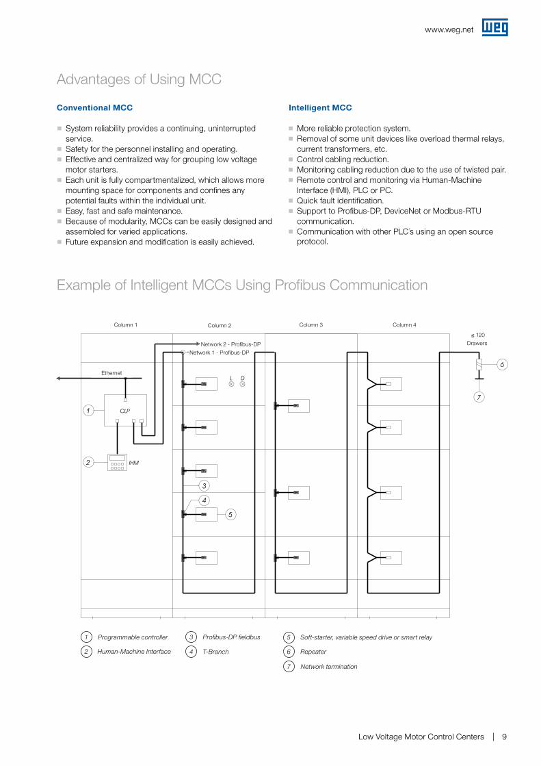
Example of Intelligent MCCs Using Profibus Communication
J ��System reliability provides a continuing, uninterrupted service.
J Safety for the personnel installing and operating. J Effective and centralized way for grouping low voltage motor starters.
J Each unit is fully compartmentalized, which allows more mounting space for components and confines any potential faults within the individual unit.
J Easy, fast and safe maintenance. J Because of modularity, MCCs can be easily designed and assembled for varied applications.
J Future expansion and modification is easily achieved.
J More reliable protection system. J Removal of some unit devices like overload thermal relays, current transformers, etc.
J Control cabling reduction. J Monitoring cabling reduction due to the use of twisted pair. J Remote control and monitoring via Human-Machine Interface (HMI), PLC or PC.
J Quick fault identification. J Support to Profibus-DP, DeviceNet or Modbus-RTU communication.
J Communication with other PLC´s using an open source protocol.
1 Programmable controller
Human-Machine Interface2 T-Branch4
Profibus-DP fieldbus3 Soft-starter, variable speed drive or smart relay5
Repeater6
Network termination7
Ethernet
Column 1 Column 2
Network 2 - Profibus-DP
Network 1 - Profibus-DP
Column 3 Column 4
≤ 120
Drawers
www.weg.net
Low Voltage Motor Control Centers10
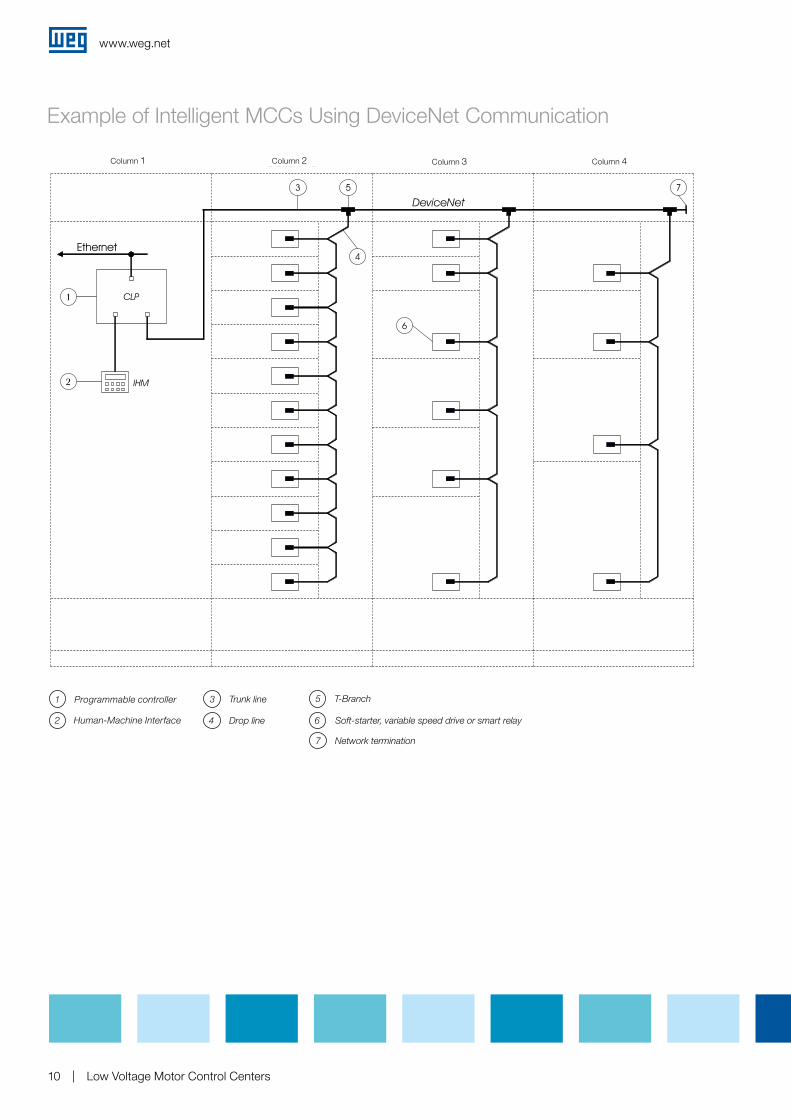
Example of Intelligent MCCs Using DeviceNet Communication
Trunk line3
Drop line4
T-Branch5
Soft-starter, variable speed drive or smart relay6
Network termination7
Column 1 Column 2 Column 3 Column 4
1 Programmable controller
Human-Machine Interface2

www.weg.net
Low Voltage Motor Control Centers 11
Intelligent MCCs - Unit Diagram
(**) Drawer position
E = Extracted
T = Test (eliminated)
I = Inserted
S0Stop
E T I (**)S7
S1Start
H1On
Network Profibus-DP
WEG Worldwide Operations
Cod
: 50
0440
30 |
Rev
: 04
| Dat
e (m
/y):
03/2
014
The
valu
es s
how
n ar
e su
bje
ct to
cha
nge
with
out p
rior
notic
e.
WEG Group - Automation Business Unit Jaraguá do Sul - SC - Brazil Phone: +55 47 3276 4000 [email protected] www.weg.net
For those countries where there is not a WEG own operation, find our local distributor at www.weg.net.
ARGENTINAWEG EQUIPAMIENTOS ELECTRICOS San Francisco - CordobaPhone: +54 3564 421 [email protected]/ar
WEG PINTURAS - PulverluxBuenos AiresPhone: +54 11 4299 [email protected]
AUSTRALIAWEG AUSTRALIAVictoria Phone: +61 3 9765 [email protected]/au
AUSTRIAWATT DRIVE - WEG GroupMarkt Piesting - ViennaPhone: +43 2633 404 [email protected]
BELGIUMWEG BENELUXNivelles - BelgiumPhone: +32 67 88 84 [email protected]/be
BRAZILWEG EQUIPAMENTOS ELÉTRICOSJaraguá do Sul - Santa CatarinaPhone: +55 47 [email protected]/br
CHILEWEG CHILESantiagoPhone: +56 2 784 [email protected]/cl
CHINAWEG NANTONGNantong - Jiangsu Phone: +86 0513 8598 [email protected]/cn
COLOMBIAWEG COLOMBIABogotáPhone: +57 1 416 [email protected]/co
FRANCEWEG FRANCESaint Quentin Fallavier - LyonPhone: +33 4 74 99 11 [email protected]/fr
GERMANYWEG GERMANY Kerpen - North Rhine Westphalia Phone: +49 2237 9291 [email protected]/de
GHANAZEST ELECTRIC GHANA WEG GroupAccraPhone: +233 30 27 664 [email protected]
INDIAWEG ELECTRIC INDIABangalore - KarnatakaPhone: +91 80 4128 2007 [email protected]/in
WEG INDUSTRIES INDIAHosur - Tamil NaduPhone: +91 4344 301 [email protected]/in
ITALYWEG ITALIACinisello Balsamo - MilanoPhone: +39 02 6129 [email protected]/it
JAPANWEG ELECTRIC MOTORSJAPANYokohama City - KanagawaPhone: +81 45 550 [email protected]/jp
MALAYSIAWATT EURO-DRIVE - WEG GroupShah Alam, SelangorPhone: 603 [email protected]
MEXICOWEG MEXICOHuehuetoca Phone: +52 55 5321 [email protected]/mx
VOLTRAN - WEG GroupTizayuca - HidalgoPhone: +52 77 5350 9354www.voltran.com.mx
NETHERLANDSWEG NETHERLANDS Oldenzaal - OverijsselPhone: +31 541 571 [email protected]/nl
PERUWEG PERULimaPhone: +51 1 472 [email protected]/pe
PORTUGALWEG EUROMaia - PortoPhone: +351 22 [email protected]/pt
RUSSIA and CISWEG ELECTRIC CIS Saint Petersburg Phone: +7 812 363 2172 [email protected] www.weg.net/ru
SOUTH AFRICAZEST ELECTRIC MOTORSWEG Group JohannesburgPhone: +27 11 723 [email protected]
SPAINWEG IBERIAMadridPhone: +34 91 655 30 [email protected]/es
SINGAPOREWEG SINGAPORE SingaporePhone: +65 [email protected]/sg
SCANDINAVIAWEG SCANDINAVIAKungsbacka - SwedenPhone: +46 300 73 [email protected]/se
UKWEG ELECTRIC MOTORS U.K.Redditch - WorcestershirePhone: +44 1527 513 [email protected]/uk
UNITED ARAB EMIRATESWEG MIDDLE EAST DubaiPhone: +971 4 813 [email protected]/ae
USAWEG ELECTRIC Duluth - GeorgiaPhone: +1 678 249 [email protected] www.weg.net/us
ELECTRIC MACHINERYWEG GroupMinneapolis - MinnesotaPhone: +1 612 378 8000www.electricmachinery.com
VENEZUELAWEG INDUSTRIAS VENEZUELAValencia - CaraboboPhone: +58 241 821 [email protected]/ve


![[PPT]Slide 1 · Web viewDC and AC Motor Drives Induction Motor Drives: Stator Voltage Control The stator voltage can be varied by three-phase ac voltage controllers, voltage-fed variable](https://static.fdocuments.us/doc/165x107/5add0e687f8b9a4a268d007a/pptslide-1-viewdc-and-ac-motor-drives-induction-motor-drives-stator-voltage-control.jpg)