CCGS Sir Wilfred Grenfell Drydocking Refit 2013
139
CCGS Sir Wilfred Grenfell Drydocking Refit 2013
Transcript of CCGS Sir Wilfred Grenfell Drydocking Refit 2013

CCGS Sir Wilfred Grenfell Drydocking Refit
2013
CCGS Sir Wilfred Grenfell Drydocking Refit 2013
F6885-12-2887
Revision 5
1
Contents Preamble ............................................................................................................................. 2 HD-01 Production Chart ................................................................................................... 11 HD-02 Dry-docking .......................................................................................................... 13 HD-03 Services ................................................................................................................. 16 HD-04 Hull Coating and Inspection ................................................................................. 20 HD-05 Hull Butts and Seams ............................................................................................ 25 HD-06 Hull Sacrificial Anodes ......................................................................................... 27 HD-07 Kort Nozzle Testing .............................................................................................. 29 HD-08 Storm Valve Inspection and Associated De-Icing Valves .................................... 31 HD-09 Ship Underwater De-Icing Valve Inspection and Replacement ........................... 34 HD-10 Sea Connections Inspection .................................................................................. 38 HD-11 Seabays, Seachests, Grids and Strainers ............................................................... 43 HD-12 Water Ballast Tank Inspections and Cleaning ...................................................... 47 H-01 Fixed Firefighting Systems ...................................................................................... 52 H-02 Galley Exhaust Fan Trunking Cleaning .................................................................. 57 H-03 Accommodation Space Ventilation Trunking Cleaning .......................................... 59 H-04 Fuel Oil, Lube Oil and Waste Tank Cleaning and Inspection ................................. 62 H-05 Annual Inspections, Port and Starboard Miranda Davits ........................................ 64 H-06 Annual Inspections, Lifeboat and Davit .................................................................. 66 H-07 Life Rafts Certification ............................................................................................ 68 H-08 Female Washroom Repairs ...................................................................................... 70 H-09 Fuel Oil Tank Calibrations ...................................................................................... 74 H-10 Steel Remediation –Save-All Above Bosun’s Locker............................................. 76 ED-01 Port Propeller, Tailshaft and Stern Tube ............................................................... 79 ED-02 Starboard Propeller, Tailshaft and Stern Tube ...................................................... 84 ED-03 Starboard Side Intermediate Bearings ................................................................... 88 ED-04 Stern Thruster Survey............................................................................................ 91 ED-05 Bow Thruster Survey ............................................................................................ 95 ED-06 Port and Starboard Rudder Stock Inspections ....................................................... 99 ED-07 Miscellaneous Piping Replacements ................................................................... 102 ED-08 Port and Starboard Fire Fighting Pump Clutch Surveys ..................................... 105 ED-09 Fire Fighting Monitor Maintenance/Survey ........................................................ 109 ED-10 Fire Fighting Pump Inspection and Alignment ................................................... 112 E-01 Starboard Inboard Main Engine Clutch Survey ..................................................... 117 E-02 Starboard Shaft Generator Clutch Survey .............................................................. 121 E-03 Safety Valve Calibration and Certification ............................................................ 125 L-01 Kongsberg Tank Level Transducers ...................................................................... 127 L-02 Clutch Control Upgrades........................................................................................ 129 L-03 Gyro Replacement .................................................................................................. 131
CCGS Sir Wilfred Grenfell Drydocking Refit 2013
F6885-12-2887
Revision 5
2
Item #: N/A SPECIFICATION TCMS Field #: N/A
Preamble 1. Intent These specifications are supplied to the shipbuilder or ship repairer, hereinafter referred to as the Contractor for the purpose of outlining the objectives, performance, standards and basic engineering requirements for the refit, including dry-docking, of the CCGS Sir Wilfred Grenfell for the Canadian Coast Guard, Department of Fisheries and Oceans for the entire refit period scheduled from Jan.10 to Feb.21, 2013. The intention is to provide sufficient information such that the Contractor, with this guidance and his own experience and knowledge of good marine practice, shall complete the work items herein by carrying out the engineering and production work, while conforming to the requirements of all applicable regulatory bodies.
The intent of this specification shall describe the necessary work involved in carrying out the ship’s Annual Refit. All work specified herein and all repairs, inspections and renewals shall be carried out to the satisfaction of the Owner’s Representative and, where applicable, the attending TCMS Surveyor. Unless otherwise specifically stated, the Owner’s Representative is the Chief Engineer. 2. Manufacturer’s Recommendations The overhaul and installation of all machinery and equipment specified herein shall be as per the manufacturer’s applicable instructions, drawings and specifications. 3. Testing and Records All test results, calibrations, measurements and readings shall be properly tabulated, compiled and three typewritten copies shall be presented to the Owner’s Representative and attending surveyors in a timely manner. All tests are to be performed to the satisfaction of the Owner’s Representative and attending TCMS surveyors.
CCGS Sir Wilfred Grenfell Drydocking Refit 2013
F6885-12-2887
Revision 5
3
4. Workmanship The contractor shall use fully qualified, certified and competent tradesmen and supervision to ensure a uniform high level of workmanship as judged by normally accepted shipbuilding standards and to the Owner’s satisfaction. 5. Facilities Quotation shall include all of the necessary parts, labour and equipment required for the erection of access staging, rigging, lighting, tugs, pilotage, necessary carnage, transportation and line handling. Ice clearing services if so required for ship movements shall form part of the bid price. During the entire refit, the contractor shall maintain all walkways, gangways, scaffolding, ladders, guardrails and similar appliances which are necessary for the safety of persons working or on business in areas where work is in progress in a state of good order. 6. Materials and Substitutions All material shall be supplied by the contractor and all materials shall be new and unused unless otherwise specified. All replacement material in the form of jointing, packing, insulation, small hardware, oils, lubricants, cleaning solvents, preservatives, paints, coatings, etc., shall be in accordance with the equipment manufacturer’s drawings, manuals or instructions. Where no particular item is specified, or where substitution must be made, the Owner’s representative must approve all material offered. The contractor shall be required to offer certificates of grade and quality on various materials to the Owner’s representative. 7. Removals Any items of equipment to be removed and subsequently reinstalled in order to carry out work specified or for access to carry out the work specified, shall be jointly inspected for damages prior to removal by both the contractor and Owner’s representative. 8. Tools The Contractor shall supply all tools necessary to perform the work specified except for certain specialty tools which shall be issued to the Contractor and shall be returned in good order to the Chief Engineer. In all other instances, ship’s tools shall not be used by the Contractor.
CCGS Sir Wilfred Grenfell Drydocking Refit 2013
F6885-12-2887
Revision 5
4
9. Exposure and Protection of Equipment The contractor shall provide adequate temporary protection for any equipment or areas affected by this refit. The contractor shall take proper precautions to maintain in a proper state of preservation any machinery, equipment, fittings, stores or items of outfit, which might become damaged by exposure. The contractor shall take proper precautions to movement of materials, sand, grit or shot blasting, airborne particles from sand, grit or shot blasting, welding, grinding, burning, gouging, painting or airborne particles of paint. Any damage shall be the responsibility of the Contractor. Owner furnished equipment and materials shall be received by the Contractor and stored in a secure warehouse or storeroom having a controlled environment appropriate to the equipment as per the manufacturer’s instructions. 10. Lighting and Ventilation Temporary lighting and/or temporary ventilation required by the Contractor to carry out any item of this specification shall be supplied, installed and maintained in a safe working condition by the Contractor and removed upon the completion of work. The Contractor may use the ship’s electrical receptacles for 120 volt power providing no circuits are overloaded. The Contractor shall use electrical equipment that is functioning properly and any work being performed by the ship’s crew shall not be impeded. 11. Cleanliness The Contractor shall at all times maintain the work areas in which his personnel have access in a clean condition and free from debris. Upon completion of this refit, the contractor shall ensure that the vessel is in a clean condition, free from all foreign material in any system or location placed there as a result of this refit. The Contractor shall provide adequate temporary protection for any equipment or areas affected by this refit. The Contractor shall dispose of any and all oil and water residue that accumulates in the machinery space bilges as a result of any refit work detailed in this specification. 12. Asbestos Any and all insulation materials supplied or installed by the Contractor shall be asbestos free and approved for the required application.
CCGS Sir Wilfred Grenfell Drydocking Refit 2013
F6885-12-2887
Revision 5
5
13. Chemists Certificates The Contractor shall supply the Owner’s representative with Marine Chemist’s or Equivalent Certificates in accordance with the TC TP 3177E directive before any cleaning, painting, or hotwork is commenced in confined spaces or machinery compartments. Certificates shall clearly state the type of work permitted and shall be renewed as required by the regulations. Additional copies of these certificates shall be posted in conspicuous locations for the information of Ship’s and Contractor personnel. The Contractor shall be aware that all storage compartments accessed by manhole covers are deemed to be ‘Confined Spaces’, this includes fuel and ballast tanks, cofferdams and chain lockers. The Contractor shall ensure that any work performed in confined spaces as defined by the Canada Labor Code complies fully with all provisions of the code and follow the Canadian Coast Guard Fleet Safety Manual for Confined Space Entry 7.D.9. and 7.D.9.(N) Version 3 dated November 24, 2006. 14. Hotwork Any item of work involving the use of heat in its execution requires that the Contractor advises the Owner’s representative prior to starting such heating and upon its completion. The Contractor shall be responsible for maintaining a competent and properly equipped fire watch during and for one full hour after all hotwork. The fire watch shall be arranged such that all sides of surfaces being worked on are visible and accessible. The Contractor shall provide sufficient suitable fire extinguishers and a fire watch during any such heating and until the work has cooled. Ship’s extinguishers are not to be used except in an emergency. The Chief Engineer, Captain and Representatives shall be notified immediately should an incident of this nature occur. The Contractor shall provide and present the necessary Certificates from a Marine Chemist’s prior to commencing any hotwork in any space. All Hotwork shall be completed in accordance with the Coast Guard Fleet Safety Manual Section 7.D.11 and 7.D.11(N). 15. Painting All new and disturbed steelwork that shall not be on the underwater wetted surface of the ship’s hull shall be protected with two (2) coats of primer. Unless otherwise stated in the individual specification item, the primer shall be Ameron Zinc Silicate (AX-9708 AMERCOAT 5105 RED OXYDE) red, or equivalent. The paint shall be applied as per the manufacturer’s instructions on their respective product data sheets. The Contractor will strictly adhere to the manufacturer’s instructions. The Contractor will perform this work to the satisfaction of a CCG contracted NACE inspector for the preparation, application and curing of all coating during the refit.

CCGS Sir Wilfred Grenfell Drydocking Refit 2013
F6885-12-2887
Revision 5
6
16. Welding The Contractor shall quote unit cost of per foot bead of welding to the hull exterior in the event of repairs to damaged areas. All welding shall be in accordance with the Canadian Coast Guard Welding Specifications for Ferrous Materials, Revision 4. (TP6151 E) The Contractor shall be currently certified by the Canadian Welding Bureau (CWB) in accordance with CWB 47.1 latest revision Division I, II or III at the time of bid closing. The Contractor shall provide a current letter of validation from the CWB indicating compliance with standard CSA W47.1, Division I, II or III. (latest revision). The Contractor may be required to provide approved procedure data sheets for each type of joint and welding position that will be involved in this refit. The Contractor may be required to supply a current Welders Ticket for each individual welder that will be involved in this refit. 17. Smoking The Public Service Smoking Policy forbids smoking in all Government ships in areas inside the ship where Contractor personnel shall be working. The Contractor shall inform shipyard workers of this policy and ensure that it is complied with. 18. Restricted Areas The following areas are out of bounds to Contractor personnel except to perform work as required by the specifications: Cabins, Offices, Wheelhouse, Control Room, Engineer’s Office, Public Washrooms, Cafeteria, Dining Room And Lounge Areas. 19. Electrical Standards Any electrical installations or renewals shall be in accordance with the latest editions of the following marine standards:
• TP 127E - Ship Safety Electrical Standards. • IEEE Standard 45 - Recommended Practice for Electrical Installation
on Shipboard If any cable installed within this contract found to be damaged, shorted or opened as a result of the manner of installation, the entire length of cable shall be replaced and installed at no cost to the Department. Plastic tie-wraps may be used to secure wiring in panels or junction boxes only.

CCGS Sir Wilfred Grenfell Drydocking Refit 2013
F6885-12-2887
Revision 5
7
20. Drawings All drawings and drawing revisions that the contractor is requested to do in the execution of this contract shall be of a quality equal to that of the drawings that are requested to be updated. For example, drawings that have been lettered and dimensioned in a professional manner are not to be updated using freehand. Prints and reproductions that a contractor is required to provide shall be made on one piece of paper and are not to be made up of smaller pieces of paper that are glued, stapled or taped together. Electronic copies of drawings shall be provided with hardcopies. 21. Lockout and Tagout Procedures The Contractor shall be responsible to protect persons working onboard the vessel while working on or near shipboard systems and equipment from accidental exposure to:
• Electrical currents. • Hydraulic pressure. • Pneumatic pressure. • Gas or steam pressure and vacuum. • High temperatures. • Cryogenic temperatures. • Radio frequency emissions. • Potential reactive chemicals. • Stored mechanical energy. • Equipment actuation.
The Contractor, under the supervision of the Chief Engineer and or the Electrical Officer, shall be responsible for the Lockout and Tagout of Equipment and systems listed in the Specification. The Contractor shall supply and install all locks and tags and complete the Lockout Tagout Log Sheet provided by the Vessel. 22. Regulatory and Authority Inspections The Contractor shall confirm a schedule of inspections with the regulatory authorities TCMS, Health Canada and Lloyd’s for all work described in this specification and shall be responsible for arranging inspections when required. 23. Transducers The Contractor shall not paint any of the transducers and they are to be afforded sufficient protection to prevent damage during hull cleaning, blasting, burning, welding and coating operations. 24. Air Testing of Structural tanks Where air testing has been approved and agreed upon by TCMS, Lloyd’s and Chief Engineer, the Contractor shall be responsible for securing all entry and exit points of the tanks to prevent the escape of test air. All materials, parts and labor shall be provided by the Contractor to perform such air tight tests. The Contractor shall be responsible for removing all materials used for these tests to make tanks air tight.

CCGS Sir Wilfred Grenfell Drydocking Refit 2013
F6885-12-2887
Revision 5
8
25. Fire Detection and Suppression Systems If any Specification item will require disturbing, removing or isolating any heat or smoke sensors / detectors, the Contractor shall advise the Chief Engineer prior to work commencing. The Ship’s Crew shall perform any such work. The Contractor shall note that failure to observe / follow proper precautions while performing work of this nature could result in system malfunction and spontaneous discharge of System Suppressant (such as Halon, CO2, FM-200 ). 26. Safety Annex The Contractor shall have in place a Safety Management System that complies with the Canada Labor Code and Provincial Regulations that deals with the Contractor responsibilities for items such as Hotwork, Confined Space Entry, Diving Operations, Working a loft, Lockout and Tagout Procedures.
• The Contractor shall be aware that the Vessel is a Federal Work Place and thereby regulated by the Canada Labor Code.
• The Contractor shall comply with the work requirements as outlined in the Canada Labor Code and applicable Provincial Regulations.
• The Contractor shall keep a log of all personnel entering and leaving any enclosed space.
• The Contractor shall note that Canadian Coast Guard Ships presently work under
the International Safety Management System (ISM) Code and each ship has a leet Safety Manual onboard. The Fleet Safety Manual shall be adhered to when contract work involves CCG personnel and any other Public Service Employee during the Contract Period. An electronic copy of the Fisheries and Oceans, Canadian Coast Guard Fleet Safety Manual (DFO-5737) – (Adobe Acrobat .PDF version) can be found at;
http://142.130.14.20/fleet-flotte/Safety/main e.htm The following is a list of applicable work instructions 7. B.2 FALL PROTECTION 7. D.9 ENTRY INTO ENCLOSED SPACES 7. D.9 (N) ENTRY INTO ENCLOSED SPACES-WORK INSTRUCTION 7. D.10 DRYDOCKING 7. D.11 HOTWORK 7. D.11 (N) HOTWORK – WORK INSTRUCTIONS 7. F.1 HANDLING FUEL, OIL AND WASTE OIL PRODUCTS 7. F.6 HANDLING STORAGE AND DISPOSAL OF HAZARDOUS MAT’LS 7. F.9 PAINT AND OTHER COATINGS 7. D.19 LOCKOUT AND TAGOU

CCGS Sir Wilfred Grenfell Drydocking Refit 2013
F6885-12-2887
Revision 5
9
27. Suspension of Work The Technical Authority reserves the right to suspend work immediately when that work is being performed in contravention of the Coast Guard’s Safety Management System. Work shall be allowed to resume when the Technical Authority, in consultation with the Contractor and PWGSC are satisfied that the agreed upon procedures are in place and being conformed to. 28. Vessel Security There shall be a Visitor Log at each main vessel access. The Contractor shall ensure that all its employees and sub-contractor personnel sign-in when entering vessel and sign-out when departing vessel. This requirement pertains to all visitors to the vessel including Inspectors or Vendors. These Visitor Logs shall be available to the Contractor’s Security Personnel in the event of any emergency. 29. WHIMIS Any WHIMIS – controlled products used onboard shall be accompanied by a current MSDS: any neutralizing chemicals or specialized protective equipment required shall be provided by the Contractor at all times when these WHIMIS – controlled products are onboard the vessel
CCGS Sir Wilfred Grenfell Drydocking Refit 2013
F6885-12-2887
Revision 5
10
30. SHIP’S PARTICULARS
• Length O.A. 68.48 Meters
• Breadth Moulded 15.00 Meters
• Depth Moulded 7.25 Meters
• Displacement at S.L.W.L. 3753 Tons
• Lightship weight 2065 Tons
• Gross Tonnage 2404 Tons
• Net Tonnage 664 Tons
• Summer Load Draft 5.424 Meters
• Year built 1985

CCGS Sir Wilfred Grenfell Drydocking Refit 2013
F6885-12-2887
Revision 5
11
Item #: HD-01 SPECIFICATION TCMS Field #: N/A
HD-01 Production Chart
Part 1: Scope:
1.1 The intent of this specification shall be to develop a production chart using MS Project encompassing all work specifications detailed in this project.
1.2 All refit specification items and shall be updated by the contractor prior to all production meetings.
Part 2: References:
2.1 Guidance Drawings/Nameplate Data:
2.2 Standards:
2.3 Regulations:
2.4 Owner Furnished Equipment:
The contractor shall supply all materials, equipment, and parts required to perform the specified work unless otherwise stated.
Part 3: Technical Description:
General
3.1 The successful contractor shall supply three hard copies and forward one electronic copy to the vessel’s Project Engineer
The contractor shall forward a copy of the Production Chart to the Contracting Authority
3.2 The chart shall show for each specification item, the start date, the duration, and the completion date.
CCGS Sir Wilfred Grenfell Drydocking Refit 2013
F6885-12-2887
Revision 5
12
3.3 A critical path of work shall be identified, which shows critical tasks that may delay the completion of the refit if they are not completed within the estimated time frame. The critical path may exist due to labour constraints or tasks that cannot be completed concurrently with other tasks.
3.4 If work arises that affects the critical path, it shall be immediately brought to the attention of the Chief Engineer, Project Engineer and PWGSC. Every effort shall be made to prevent completion delay.
Part 4: Proof of Performance
4.1 The Production Charts shall be done to the satisfaction of the Chief Engineer and PWGSC.
Part 5: Deliverables:
5.1 The successful Contractor shall supply three copies of a detailed bar chart showing the planned work schedule for the ship's refit. This bar chart shall show, for each specification item, the start date, the duration and the completion date.
5.2 Three copies of the original and three copies of each weekly update shall be given to the Chief Engineer one day prior to each weekly Production Meeting.
5.3 The bar chart shall be updated weekly or for each production meeting to reflect the actual production on the refit and changes to the anticipated completion dates of each individual item. The Contractor shall include on the updates to the production chart any Work Arising from PWGSC 1379 action and indicate how the additional work will impact the completion schedule for the vessel.

CCGS Sir Wilfred Grenfell Drydocking Refit 2013
F6885-12-2887
Revision 5
13
Item #: HD-02 SPECIFICATION TCMSB Field #: N/A
HD-02 Dry-docking Part 1: Scope: 1.1 The intent of this specification shall be to have the vessel docked and undocked with necessary lay days required to carry out the specified work with reasonable time allowance to deal with any work arising. Part 2: References: 2.1 Guidance Drawings/Nameplate Data 2.1.1 Docking Plan: # NJC-10-106 2.2 Standards 2.2.1 N/A 2.3 Regulations 2.3.1 CSA Marine Machinery Regulations 2.4 Owner Furnished Equipment 2.4.1 The contractor shall supply all materials, equipment, and parts required to perform the specified work unless otherwise stated. Part 3: Technical Description: 3.1 General 3.1.1 The contractor shall perform crankshaft deflections on all four main engines before the dry docking, immediately after the dry docking and after the undocking. The engines will be at pre-heat temperature. Readings shall be taken in the presence of the Chief Engineer or designate, recorded in the Ship Condition Report and a copy given to the Chief Engineer following each before and after set. 3.1.2 The contractor shall supply the services of a diver to confirm that the vessel settles evenly on the bilge and keel blocks and to ensure that the transducers in the hull, anodes and sea inlet grids are clear of the blocks and accessible. The Contractor shall prepare these blocks and necessary shoring to maintain true alignment of the vessel’s hull and machinery throughout the dry-docking period. A minimum of 4 feet shall be available below the keel. If any hull fittings are covered, the Contractor shall be responsible for all labour and materials required for making alternate arrangements to drain tanks and/or move blocks to gain access to areas of specified work. 3.1.3 The contractor shall quote on the total lay day cost and unit lay day cost. Quote

CCGS Sir Wilfred Grenfell Drydocking Refit 2013
F6885-12-2887
Revision 5
14
shall include any tug or pilot service cost. 3.1.4 The available deck crew is responsible for handling ship’s lines but may require additional personnel (contractor supply) as required. The contractor shall quote on the services of four persons for line handling. The contractor shall discuss with the Commanding Officer prior to moving the vessel. 3.1.5 The overhanging transom shall be shored by the Contractor in way of Frame 5 approximately 4.5 m off the centerline, Port and Starboard immediately after vessel is dry docked for duration of the dry docking with removal only for periods when necessary for specified work. 3.1.6 Prior to dry-docking, all tanks on the vessel shall be sounded and contents recorded in the vessel’s Ship Condition Report. Copy shall be signed by the ship’s Captain, Chief Engineer and the Contractor’s Docking Master. 3.1.7 The Contractor shall be responsible for the safe transfer of the ship from its pre- docking berth or location onto its docking blocks. During docking, radio contact shall be maintained between the vessel’s Captain and the Contractor’s Docking Master. 3.1.8 Following the dry docking all tanks will be sounded and recorded in the Ship Condition Report. Copies shall be signed and given to the ship’s Captain, Chief Engineer and the Contractor’s Docking Master. 3.1.9 Following dry-docking, the underwater hull shall be cleaned by high pressure fresh water washing 2000 psi minimum to remove all marine growth and allow preliminary inspection. 3.1.10 Prior to commencing hydro-blasting, all hull mounted equipment and openings shall be fully protected. 3.1.11 The contractor shall then remove and mark the following docking plugs and give to the Chief Engineer. # 1 WB Port and Starboard – 2 each # 20 WB Center – 1 each # 2 WB Port and Starboard – 1 each # 7 WB Port and Starboard – 1 Each # 15 WB Port and Starboard – 1 each # 17 FW Center – 1 each # 16 FW Port and Starboard – 1 each # 18 WB Center – 1 each All tanks emptied shall be recorded in the Ship Condition Report. Copies shall be held by the Contractor, ship’s Captain and Chief Engineer. 3.1.12 The Contractor shall not remove or transfer any tank contents without first discussing same with the ship’s Captain and Chief Engineer.
CCGS Sir Wilfred Grenfell Drydocking Refit 2013
F6885-12-2887
Revision 5
15
3.1.13 For any Hydrostatic testing of tanks, the testing shall be carried out uniformly so that excess local strain shall not ensue. Not more than one (1) tank at a time shall be filled without symmetrical compensation on the opposite side of the ship. Additional shoring for testing deep tanks shall be fitted as/when required. 3.1.14 At undocking, all sea valves shall be shut prior to undocking and checked for water tightness during the undocking period by the Contractor. All tanks shall be filled to obtain the same Drafts and Trim as at docking and the condition agreed by the ship’s Captain, Chief Engineer and Contractor’s Docking Master. 3.2 Location 3.2.1 N/A 3.3 Interferences 3.3.1 Contractor is responsible for the identification of interference items, their temporary removal, storage and refitting to vessel. Part 4: Proof of Performance 4.1 Inspection 4.1.1 All work shall be completed to the satisfaction of the Chief Engineer. 4.2 Testing 4.2.1 N/A 4.3 Certification 4.3.1 N/A Part 5: Deliverables: 5.1 Drawings/Reports 5.1.1 All reports from the work specified shall be given to the Chief Engineer. 5.2 Spares 5.2.1 N/A 5.3 Training 5.3.1 N/A 5.4 Manuals 5.4.1 N/A
CCGS Sir Wilfred Grenfell Drydocking Refit 2013
F6885-12-2887
Revision 5
16
Item #: HD-03 SPECIFICATION TCMS Field #: N/A
HD-03 Services Part 1: Scope: 1.1 The intent of this specification shall be to supply and connect the following services to the vessel during the drydock period as applicable and disconnected when leaving. The Contractor shall supply all material and labor to the point of onboard connection. The Contractor’s quote shall include all crane / scaffolding required for connection and disconnection. The Contractor’s bid price shall be broken down by item. Part 2: References: 2.1 Guidance Drawings/Name plate Data 2.1.1 N/A 2.2 Standards 2.2.1 N/A 2.3 Regulations 2.3.1 N/A 2.4 Owner Furnished Equipment 2.4.1 The contractor shall supply all materials, equipment, and parts required to perform the specified work unless otherwise stated. Part 3: Technical Description: 3.1 General
3.1.1. Metered electrical service 600 VAC, 3 phase, 60 Hz, 440A continuous shall be supplied and maintained. Quote on supplying 300,000 kWh to be adjusted up or down by 1379 action. Quote shall also include the unit cost per kWh for adjustment purposes. A ground cable shall be solidly attached to ship’s hull. The contractor shall supply and install the electrical cable and kilowatt hour meter. The vessel’s electrical cable shall not be cut. The ship’s shore power cable and plugs shall not to be disconnected or opened. The 300,000 kWh quoted above shall be for the vessel’s own use. Meter readings shall be taken and recorded by the Contractor and ship’s Electrical Officer at time of connection and disconnection. The contractor shall supply this electrical service from the starting date to the completion date of the contract. The Contractor shall supply separate electrical service for contractor items in this specification.

CCGS Sir Wilfred Grenfell Drydocking Refit 2013
F6885-12-2887
Revision 5
17
3.1.2. Water connections shall be supplied and connected to the ship’s fire main at 80
psi with a 2 inch diameter hose. Pressure shall be maintained to the vessel at all times continuous 24 hours per day. The Contractor shall supply a pressure reducing valve with a pressure gauge which shall be fitted before the connection onboard the ship. The connection shall be such that when fully opened 2 hydrants on the vessel shall result in no noticeable decrease in the flow of water. The contractor shall be responsible for ensuring the water line does not freeze by providing a bleed connection led to the dock bottom.
3.1.3. The Potable Fresh Water connection to ship’s domestic system, minimum 60 psi shall be connected to the shore connection Port Foc’sle Deck through a Contractor supplied / installed pressure reducing valve and gauge. The contractor shall be responsible for ensuring a continuous supply and that the water line does not freeze by providing a bleed connection led to the dock bottom. The Contractor shall supply this Potable Fresh Water until the fresh water system onboard is put back in service. The Contractor is to supply any fresh water used for cleaning, testing or flushing of tanks as required by the specification.
3.1.4. The Contractor shall make connection of one (1) 3 inch sewage discharge line fitted to the ship’s overboard discharge opening at ship’s shell and lead to the Contractor’s sewage outlet.
3.1.5. The Contractor shall make connection of six (6) 3 inch grey water discharge lines fitted to the ship’s overboard discharge openings at ship’s shell and lead to the Contractor’s sewage outlet.
3.1.6. The Contractor shall supply labour and services for the rigging of two (2) separate and independent boarding gangways complete with safety nets and two handrails. The gangways (Contractor supplied) shall be suitably illuminated for use at night. The Contractor shall arrange these two (2) gangways as to provide two (2) separate and distinctive fire escape routes.
3.1.7. The Contractor shall supply suitable Refuse containers 6 square meters on the after deck. Refuse shall be removed from the ship when container is 80% full. The contractor shall be responsible for provision of suitable containers and any costs associated with waste disposal including crane, transportation and regulations that may be in place. This shall include hazardous materials and recyclables. The contractor shall advise the owner’s representative of any such regulations or practices at the pre-refit meeting.
3.1.8. The Contractor shall supply four (4) independent and private telephone lines. The service shall not to be routed through the contractor’s switchboard and all lines shall be totally independent. They shall be connected to the Shore Phone connection box located on the winch room aft bulkhead. All lines shall be active 24 hours per day and have long distance dialing capabilities for the duration of the contract. The cost of connections, removal and local service charges shall be included. Long distance charges shall be paid by 1379 action at the end of the refit. The Contractor shall be responsible for giving
CCGS Sir Wilfred Grenfell Drydocking Refit 2013
F6885-12-2887
Revision 5
18
notice to Telephone Company of connection / disconnection times. Contractor to supply listing of Contractor telephone numbers, fire, police and emergency numbers to Chief Engineer upon dry-docking.
3.1.9. The contractor shall supply one cable TV connection to the vessel in the winch room.
3.1.10. The contractor shall provide labour and equipment (crane) to erect, as necessary, scaffolding and staging and temporary lighting to facilitate the specified exterior work. The scaffolding and staging and temporary lighting shall be removed when the work is complete by said Contractor.
3.1.11. The Contractor shall allow $1000.00 in bid for crane usage for vessel’s purpose and not for Contractor work. Contractor shall include an hourly rate for crane to be used to adjust cost up or down by 1379 action.
3.1.12. During the entire refit, the Contractor shall maintain in a state of good order and cleanliness all walkways, gangways and places where work is ongoing.
3.1.13. Ice clearing services if so required for ship shall form part of the Contractor’s bid price.
3.1.14. The Contractor shall quote on removing from ship’s bilges 12 cubic meters of oil/water mixture. Quotation shall include crane, pumping, trucking and disposal of waste mixture. Contractor to provide identity of firm(s) licensed for pumping and disposal of waste oil. The Contractor shall quote a unit price per cubic meter to be adjusted up or down by 1379 action.
3.1.15. Dock and Sea Trials: On completion of all specification items, dock trials and sea trials will be carried out as a functional test of the ships propulsion system and maneuvering systems. Dock trials will last a minimum of one (1) hour. Sea trials will last a minimum of four (4) hours. Trials will include ahead and astern movements at various power levels. Trials will be carried out to the satisfaction of the Chief Engineer .The contractor is to have sufficient supervisory staff on board during these trials to witness the operation of machinery and systems that were worked on during the refit. 3.2 Location 3.2.1 N/A 3.3 Interferences 3.3.1 The Contractor is responsible for the identification of interference items, their temporary removal, storage and refitting to the vessel.

CCGS Sir Wilfred Grenfell Drydocking Refit 2013
F6885-12-2887
Revision 5
19
Part 4: Proof of Performance 4.1 Inspection 4.1.1 All work shall be to the satisfaction of the Chief Engineer. 4.2 Testing 4.2.1 N/A 4.3 Certification 4.3.1 N/A Part 5: Deliverables: 5.1 Drawings/Reports 5.1.1 All reports from the work specified shall be given to the Chief Engineer.

CCGS Sir Wilfred Grenfell Drydocking Refit 2013
F6885-12-2887
Revision 5
20
Spec item #: HD-04 SPECIFICATION TCMS Field #: N/A
HD-04 Hull Coating and Inspection Part 1: Scope:
1.1 The intent of this item shall be to clean, repair coating, and inspect the hull of the vessel. The entire underwater area of the ship’s hull is coated with abrasion resistant coating products.
1.2 For purposes of clarity this specification item shall be dealt with in two sections. 1.2.1. The underwater portion of the hull 1.2.2. The above waterline portion of the hull
1.3 This work shall be carried out in conjunction with the following:
• HD-06 Hull Anodes Replacement. • HD-12 Ballast Tank Testing and Coating.
Part 2: References: 2.1 Guidance Drawings/Nameplate Data 2.1.1 NJC-11-100 2.2 Standards 2.2.1 Ships ISM Hot-Work, Confined Space, Fall Protection Lockout Procedures 2.2.2 Steel Structures Painting Council Standard (SSPC) 2.3 Regulations 2.3.1 N/A 2.4 Owner Furnished Equipment 2.4.1 The contractor shall supply all materials, parts, equipment, labour and tools required to perform the specified work. Part 3: Technical Description: 3.1 General Underwater Hull 3.1.1 The entire underwater area of the ship from the keel to the top of the light waterline shall be hydro blasted and cleaned of all marine growth and salts. This shall include rudders, propellers, nozzles and thruster tunnels. The cleaning shall be done
CCGS Sir Wilfred Grenfell Drydocking Refit 2013
F6885-12-2887
Revision 5
21
immediately after the vessel is dry-docked. 3.1.2 The entire underwater hull shall then be inspected by the Chief Engineer and attending TCMS and NACE inspectors. The Contractor shall supply and erect staging/scaffolding as required for the inspection. 3.1.3 The contractor shall make repairs to areas where the hull coating is missing as directed by the Chief Engineer.
3.1.4 In order to avoid any confusion as to the total area to be repaired, the Contractor shall assign a representative, who along with the owner’s representative to view the ship as it sits on the blocks subsequent to cleaning but prior to coating repairs. The two representatives shall view the ship and agree upon the total area of the hull that shall be repaired and coated. 3.1.5 The Contractor shall plug deck scuppers and discharges as well as take other measures necessary to prevent any liquids from contaminating areas being prepared or coated. The contractor shall also take measures to ensure that no damage, unnecessary cleaning, or any repairs result from either the hull preparation process or coating application. Measures shall be taken to ensure that surfaces and equipment, other than those specified, are not coated and that the coating shall not block any inlets or discharges in the shell. Deck machinery and other gear shall be protected from damage by grit and coatings. 3.1.6 All traces of grit used for blast cleaning, shall be removed by the Contractor. The Contractor shall be responsible and liable for ensuring that the hull is clear and clean prior to, during and immediately after the coating application. 3.1.7 Abrasive blast material shall not be permitted to enter any part of the vessel. The Contractor shall ensure that every opening into the vessel where grit may gain entry is covered. 3.1.8 The contractor shall quote on making repairs to approximately 300 square meters of damaged hull coating. The repairs shall include surface preparation, epoxy coating to damaged areas. The quote shall include the unit cost per square meter and shall be used to adjust the total area for the work up or down by PWGSC 1379 action. The total area is 1500 square metres. 3.1.9 Suitable storage facilities shall be provided close to the work site for the necessary materials and equipment and they must be maintained at the recommended temperature of the coating manufacturer to ensure ease of preparation and application. 3.1.10 The mixing and spraying equipment shall be kept heated and protected as necessary, while in use, to ensure that the coating is maintained and the recommended temperature.

CCGS Sir Wilfred Grenfell Drydocking Refit 2013
F6885-12-2887
Revision 5
22
NOTE: The equipment used to apply the coating shall meet the specifications of the coating manufacturer. Surface Preparation 3.1.11 Abrasive Blast all bare and rusted areas to SSPC-SP-10 Near White Metal. All edges of intact epoxy coating shall be feathered back to accept new coating. “Sweep Blast” the remaining entire hull intact coating to create a profile to accept new coating. Primer - Touchup 3.1.12 Apply one touch up coat of Amercoat 238 Abrasion Resistant Epoxy to bare blasted areas only. Apply @ 10 mils DFT. Intermediate Coat 3.1.13 Apply one full coat of Amercoat 238 Abrasion Resistant Epoxy to entire underwater hull area. Apply @ 10 mils DFT. Colour Red Oxide. Topcoat 3.1.14 Apply one full coat of Amercoat 339 Low Friction Hull Coating to entire underwater hull area. Apply @ 8 mils DFT. Colour Black. 3.1.15 Sea-bay grids shall be protected during application of the coating and orifices shall be proven original diameter before undocking. The transducers shall be protected as well. 3.1.16 Zinc anodes shall be protected from coating and the protection shall be removed prior to undocking. All new anodes shall be installed prior to coating. 3.1.17 The Contractor shall perform the work in strict accordance with Ameron’s application instructions for each applicable coating. 3.2 Anchor Pockets 3.2.1 The anchor pockets shall be completely abrasive blasted to SSPC-SP10 to achieve an anchor profile of 2 -3 mils. The Contractor shall quote on 4 square meters for each pocket. 3.2.2 The contractor shall apply two coats of Amercoat 238 Abrasion Resistant Epoxy at 10 mils DFT per coat with sufficient feathering. The final coat of Amercoat 238 shall be followed by one coat of Amercoat 339 Low Friction Hull Coating at 8 mils DFT. Above Waterline Hull Surface Preparation 3.3.1 Abrasive Blast all bare and rusted areas to SSPC-SP-10 Near White Metal and feather back existing intact coating to accept new coating. The contractor shall quote on making repairs to approximately 200 square meters of damaged hull coating. The repairs shall include surface preparation and primer coatings to damaged areas. The quote shall include the unit cost per square meter and shall be used to adjust up or down by PWGSC 1379 action the total area for the work. The total area is 450 square meters.
CCGS Sir Wilfred Grenfell Drydocking Refit 2013
F6885-12-2887
Revision 5
23
Primer 3.3.2 Apply two touch up coats of Amercoat 5105 Primer to all blasted areas. Apply @ 2 to 3 mils DFT. Topcoat 3.3.3 Apply two full coats of Amercoat 5450 Topcoat to entire area. Apply @ 2 to 3 mils DFT. Colour Coast Guard Red (509-102). 3.3.4 The waterline shall be cut in and the shell of the ship from the lightship waterline and up one foot shall be given one coat of anti-corrosive paint. Bare areas of the hull shall be given one coat of Contractor supplied primer and then the entire hull area above the underwater body given one coat of owner supplied red paint. 3.3.5 All draft marks, load lines, thruster symbols and hull symbols shall be painted with two coats using Contractor supplied white paint as per ship’s painting schedule. 3.3.6 The thickness determination of the new coating shall be verified and recorded at three positions on each repair area. Measuring points shall be as indicated by the Owner’s representative. 3.3.7 The hull markings including the load line, draft marks, thruster symbols, ship’s name, Port of Registry, white slash with black trim, Coast Guard service title, Fisheries and Oceans departmental signature shall be painted on as directed by Chief Officer. The vessel shall supply templates for the Coast Guard service title and Fisheries and Oceans departmental signature. 3.3.8 The areas of the ship’s hull as designated by the Chief Officer for Port and Starboard sides shall have the white paint “RESCUE ZONE” stenciling renewed. (Located between Fr. 35 and 48) Stenciling and white paint shall be owner supplied (Amercoat 400). 3.3.9 The Contractor shall perform the work in strict accordance with Ameron’s application instructions for each applicable coating. 3.3.10 All work shall be done to the satisfaction of the Chief Engineer and Chief Officer. 3.3 Location 3.3.1 Exterior Hull 3.4 Interferences 3.4.1 The Contractor is responsible for the identification of all interference items, their temporary removal, storage and refitting to vessel. Part 4: Proof of Performance

CCGS Sir Wilfred Grenfell Drydocking Refit 2013
F6885-12-2887
Revision 5
24
4.1 Inspection 4.1.1 All work shall be completed to the satisfaction of the Chief Engineer, Chief Officer and NACE Inspector. 4.2 Testing 4.2.1 The contractor shall prove to the owners the DFT measurements at areas where the coating was completely missing. 4.3 Certification 4.3.1 The Contractor shall supply documentation of coatings applied. Part 5: Deliverables: 5.1 Drawings/Reports 5.1.1 The thickness determination DFT of the new coatings applied shall be verified and recorded. Reports shall be given to Chief Engineer. 5.1.2 All reports from the work specified shall be given to the Chief Engineer.

CCGS Sir Wilfred Grenfell Drydocking Refit 2013
F6885-12-2887
Revision 5
25
Spec item #: HD-05 SPECIFICATION TCMS Field #:
3LL040
HD-05 Hull Butts and Seams Part 1: Scope: 1.1 The intent of this item shall be to inspect the hull plate welding of butts and seams and to repair where deemed necessary. 1.2 This work shall be completed in conjunction with: 1.2.1. HD-02 Dry-Docking. 1.2.2. HD-07 Kort Nozzle Testing. 1.2.3. HD-11 Sea-Bays, Sea-Chest and Strainer Cleaning and Painting. 1.2.4. HD-06 Hull Sacrificial Anodes. 1.2.5. HD-04 Hull Coating and Inspection. 1.2.6. HD-12 Water ballast Tank Surveys and Cleaning / Coating. Part 2: References: 2.1 Guidance Drawings / Name Plate Data 2.1.1 N/A 2.2 Standards 2.2.1 Canadian Coast Guard Welding Specifications for Ferrous Materials, Revision 4. (TP6151 E) and all welding shall be as per specification preamble. 2.3 Regulations 2.3.1 CSA Hull and Construction Regulation 2.3.2 Ships ISM Safety Procedures 2.3.3 CG Hotwork Procedures 2.4 Owner Furnished Equipment 2.4.1 The contractor shall supply all materials, equipment, labour and parts required to perform the specified work unless otherwise stated. Part 3: Technical Description: 3.1 General 3.1.1 The hull plate welding of butts and seams to be repaired will be determined at the time of the Hull Survey by the TCMS and the Chief Engineer.

CCGS Sir Wilfred Grenfell Drydocking Refit 2013
F6885-12-2887
Revision 5
26
3.1.2 Seams and butts selected for repair shall be marked, cleaned to sound metal by air arc or grinding and brought up to original levels by approved welding techniques and materials. 3.1.3 The Contractor shall quote on 1,000 feet of gouging and 4,000 bead feet of weld. The Contractor shall quote per bead foot for adjustment purposes up or down by PWGSC 1379 action. 3.1.4 Any butts and seams falling in way of fuel tanks that require gas freeing and certification for hot work will be recovered by PWGSC 1379 action. Butts and seams falling in way of ballast / void tanks that are painted shall require paint work to be touched up in way of damage by the Contractor. 3.1.5 All work shall be to the satisfaction of TCMS and the Chief Engineer. 3.2 Location 3.2.1 Outside Hull area. 3.3 Interferences 3.3.1 The Contractor shall be responsible for all removals required for completion of this item. Any removals shall be replaced in good order after the completion of all work. 3.3.2 The Contractor is responsible for the identification of all interference items, their temporary removal, storage, and refitting to vessel. Part 4: Proof of Performance 4.1 Inspection 4.1.1 TCMS Inspectors and Chief Engineer. 4.2 Testing 4.2.1 N/A 4.3 Certification 4.3.1 All new welding shall have full documentation of the Type of welding completed and the welding procedure and all welding shall be as per specification preamble. Part 5: Deliverables: 5.1 Drawings/Reports 5.1.1 All reports from the work specified shall be given to the Chief Engineer. 5.2 Spares 5.2.1 N/A 5.3 Training
CCGS Sir Wilfred Grenfell Drydocking Refit 2013
F6885-12-2887
Revision 5
27
5.3.1 N/A Spec item #: HD-06 SPECIFICATION TCMS Field #: N/A
HD-06 Hull Sacrificial Anodes Part 1: Scope: 1.1 The intent shall be to replace all wasted anodes located on the underwater areas of the vessel’s hull. New anodes shall be installed in the same positions as existing unless otherwise instructed by the Chief Engineer.
1.2 This work shall be carried out in Conjunction with the following: 1.2.1 HD-04 Hull Coating and Inspection. 1.2.2 HD-11 Sea Bay, Sea Chest Cleaning.
Part 2: References: 2.1 Guidance Drawings/Nameplate Data 2.1.1 N/A. 2.2 Standards 2.2.1 Ships ISM Hot-Work, Confined Space, Fall Protection & Lockout Procedures. 2.3 Regulations 2.3.1 N/A. 2.4 Owner Furnished Equipment 2.4.1 The contractor shall supply all materials, parts, equipment, labour and tools required to perform the specified work. Part 3: Technical Description: 3.1 General 3.1.1 All zinc anodes on the hull, propeller, nozzles, rudders, thruster tunnels, sea bays and sea chest shall be inspected for wastage. The Contractor shall bid on supplying and installing (98) ninety eight 10 kilogram zinc anodes as directed by the Chief Engineer. The quote shall include the cost for each anode and shall be used to adjust up or down by PWGSC 1379 action the total anodes replaced. The quote shall be for the removal and installation of each anode. 3.1.2 The old mounting straps shall be removed and the welds for same ground flush prior to hull coating.
CCGS Sir Wilfred Grenfell Drydocking Refit 2013
F6885-12-2887
Revision 5
28
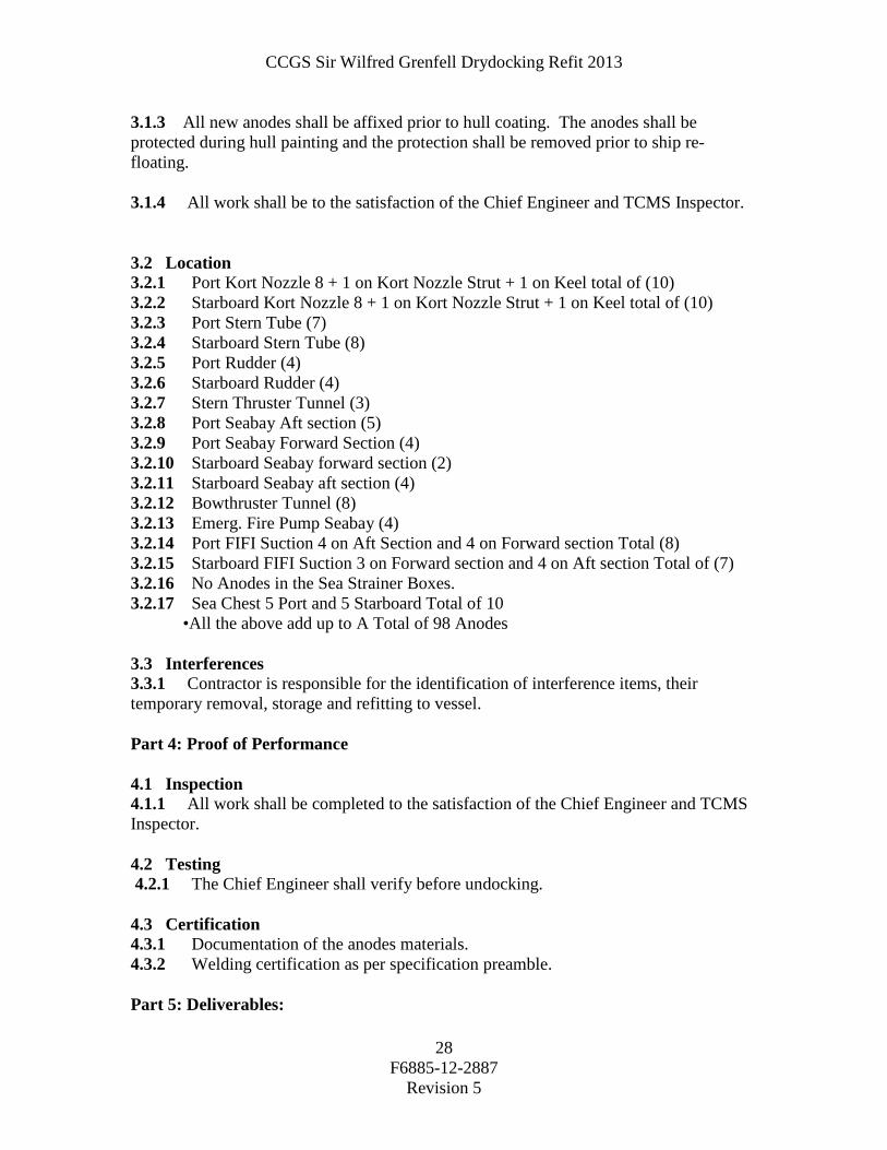
3.1.3 All new anodes shall be affixed prior to hull coating. The anodes shall be protected during hull painting and the protection shall be removed prior to ship re-floating. 3.1.4 All work shall be to the satisfaction of the Chief Engineer and TCMS Inspector. 3.2 Location 3.2.1 Port Kort Nozzle 8 + 1 on Kort Nozzle Strut + 1 on Keel total of (10) 3.2.2 Starboard Kort Nozzle 8 + 1 on Kort Nozzle Strut + 1 on Keel total of (10) 3.2.3 Port Stern Tube (7) 3.2.4 Starboard Stern Tube (8) 3.2.5 Port Rudder (4) 3.2.6 Starboard Rudder (4) 3.2.7 Stern Thruster Tunnel (3) 3.2.8 Port Seabay Aft section (5) 3.2.9 Port Seabay Forward Section (4) 3.2.10 Starboard Seabay forward section (2) 3.2.11 Starboard Seabay aft section (4) 3.2.12 Bowthruster Tunnel (8) 3.2.13 Emerg. Fire Pump Seabay (4) 3.2.14 Port FIFI Suction 4 on Aft Section and 4 on Forward section Total (8) 3.2.15 Starboard FIFI Suction 3 on Forward section and 4 on Aft section Total of (7) 3.2.16 No Anodes in the Sea Strainer Boxes. 3.2.17 Sea Chest 5 Port and 5 Starboard Total of 10 •All the above add up to A Total of 98 Anodes 3.3 Interferences 3.3.1 Contractor is responsible for the identification of interference items, their temporary removal, storage and refitting to vessel. Part 4: Proof of Performance 4.1 Inspection 4.1.1 All work shall be completed to the satisfaction of the Chief Engineer and TCMS Inspector. 4.2 Testing 4.2.1 The Chief Engineer shall verify before undocking. 4.3 Certification 4.3.1 Documentation of the anodes materials. 4.3.2 Welding certification as per specification preamble. Part 5: Deliverables:

CCGS Sir Wilfred Grenfell Drydocking Refit 2013
F6885-12-2887
Revision 5
29
5.1 Drawings/Reports 5.1.1 Documentation of anode material. 5.1.1 All reports from the work specified shall be given to the Chief Engineer. Spec item #: HD-07 SPECIFICATION TC Field #: 3H057-58
HD-07 Kort Nozzle Testing Part 1: Scope: 1.1 The intent of this item shall be to inspect and air test Port and Starboard Kort Nozzles for TCMS and to obtain a five year credit for the survey. . 1.2 This work shall be carried out in Conjunction with: 1.2.1 HD-04 Coating and Inspection 1.2.2 HD-06 Hull Sacrificial Anodes 1.2.3 HD-11 Water Ballast Inspections and Cleaning Part 2: References: 2.1 Guidance Drawings/Nameplate Data 2.1.1 N/A. 2.2 Standards 2.2.1 Canadian Coast Guard Welding Specifications for Ferrous Materials, Revision 4. (TP6151 E). 2.3 Regulations 2.3.1 CSA Hull and Construction Regulation. 2.3.2 Ships ISM Safety Procedures. 2.4 Owner Furnished Equipment 2.4.1 The contractor shall supply all materials, equipment, parts and labour required to perform the specified work unless otherwise stated. Part 3: Technical Description: 3.1 General 3.1.1. The Port and Starboard Kort Nozzles shall have their drain plugs removed then be
air tested to a maximum of 3 psi and shall be checked for leakage. Prior to removal of drain plugs the Contractor shall notify the Chief Engineer to witness the presence of any leakage.
CCGS Sir Wilfred Grenfell Drydocking Refit 2013
F6885-12-2887
Revision 5
30
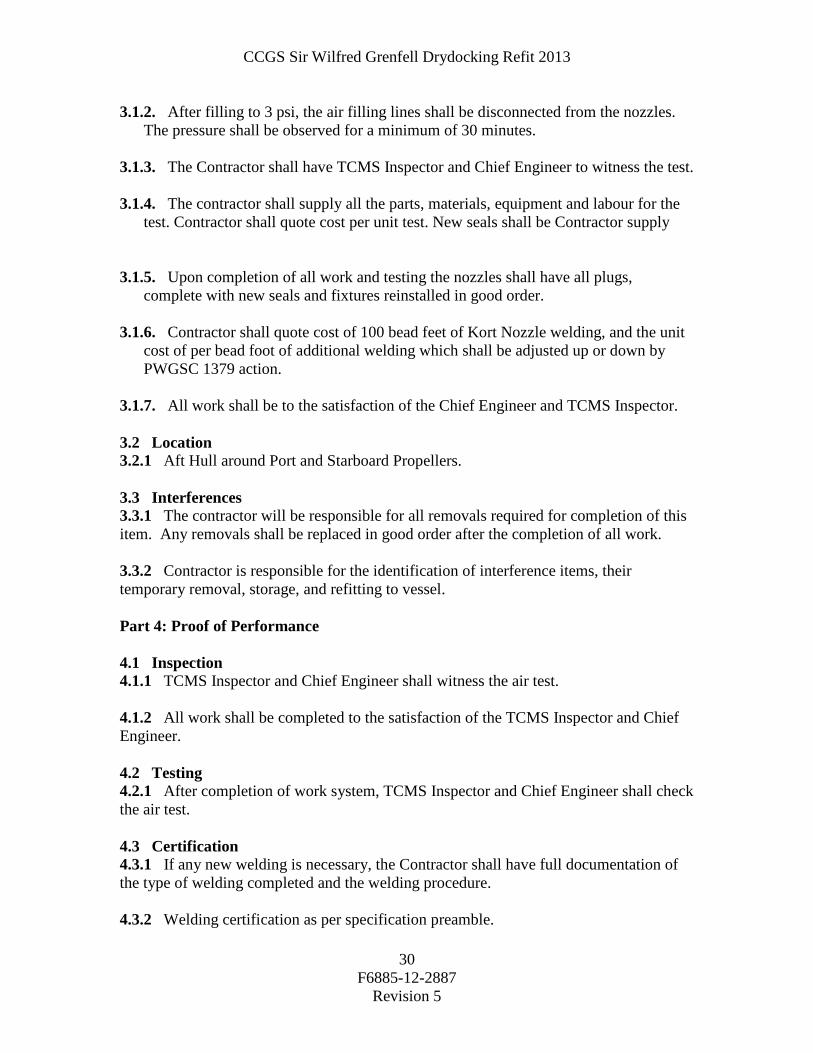
3.1.2. After filling to 3 psi, the air filling lines shall be disconnected from the nozzles.
The pressure shall be observed for a minimum of 30 minutes.
3.1.3. The Contractor shall have TCMS Inspector and Chief Engineer to witness the test.
3.1.4. The contractor shall supply all the parts, materials, equipment and labour for the test. Contractor shall quote cost per unit test. New seals shall be Contractor supply
3.1.5. Upon completion of all work and testing the nozzles shall have all plugs, complete with new seals and fixtures reinstalled in good order.
3.1.6. Contractor shall quote cost of 100 bead feet of Kort Nozzle welding, and the unit cost of per bead foot of additional welding which shall be adjusted up or down by PWGSC 1379 action.
3.1.7. All work shall be to the satisfaction of the Chief Engineer and TCMS Inspector. 3.2 Location 3.2.1 Aft Hull around Port and Starboard Propellers. 3.3 Interferences 3.3.1 The contractor will be responsible for all removals required for completion of this item. Any removals shall be replaced in good order after the completion of all work. 3.3.2 Contractor is responsible for the identification of interference items, their temporary removal, storage, and refitting to vessel. Part 4: Proof of Performance 4.1 Inspection 4.1.1 TCMS Inspector and Chief Engineer shall witness the air test. 4.1.2 All work shall be completed to the satisfaction of the TCMS Inspector and Chief Engineer. 4.2 Testing 4.2.1 After completion of work system, TCMS Inspector and Chief Engineer shall check the air test. 4.3 Certification 4.3.1 If any new welding is necessary, the Contractor shall have full documentation of the type of welding completed and the welding procedure. 4.3.2 Welding certification as per specification preamble.

CCGS Sir Wilfred Grenfell Drydocking Refit 2013
F6885-12-2887
Revision 5
31
Part 5: Deliverables: 5.1 Drawings/Reports 5.1.1 All reports from the work specified shall be given to the Chief Engineer. Spec item #: HD-08 SPECIFICATION TC Field #: 3LL090
HD-08 Storm Valve Inspection and Associated De-Icing Valves Part 1: Scope: 1.1 The intent of this item shall be to open the above noted storm valves and associated De-Icing Valves valves for inspection and to obtain a survey credit by TCMS. The contractor shall be responsible for notifying TCMS for all inspections. Part 2: References: 2.1 Guidance Drawings/Nameplate Data 2.1.1 N/A. 2.2 Standards 2.2.1 Canadian Coast Guard Welding Specifications for Ferrous Materials, Revision 4. (TP6151 E). 2.3 Regulations 2.3.1 CSA Hull and Construction Regulation. 2.3.2 Ships ISM Safety Procedures. 2.4 Owner Furnished Equipment 2.4.1 The contractor shall supply all materials, equipment, parts and labor required to perform the specified work unless otherwise stated. Part 3: Technical Description: 3.1 General 3.1.1. The Contractor shall note that the affected cabins and spaces will be occupied
while this work is ongoing. The contractor shall install blanks over access covers while the work is in progress.
3.1.2. The noted valves shall be opened up for cleaning and inspection. The contractor
shall be responsible for the removal and replacement of panels in the cabins to provide access to the valves as required. The valve flappers shall be removed and
CCGS Sir Wilfred Grenfell Drydocking Refit 2013
F6885-12-2887
Revision 5
32
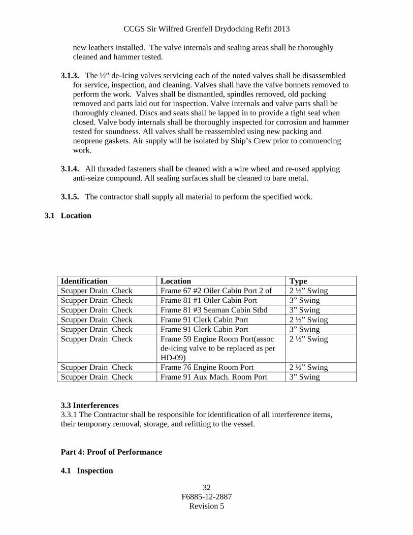
new leathers installed. The valve internals and sealing areas shall be thoroughly cleaned and hammer tested.
3.1.3. The ½” de-Icing valves servicing each of the noted valves shall be disassembled
for service, inspection, and cleaning. Valves shall have the valve bonnets removed to perform the work. Valves shall be dismantled, spindles removed, old packing removed and parts laid out for inspection. Valve internals and valve parts shall be thoroughly cleaned. Discs and seats shall be lapped in to provide a tight seal when closed. Valve body internals shall be thoroughly inspected for corrosion and hammer tested for soundness. All valves shall be reassembled using new packing and neoprene gaskets. Air supply will be isolated by Ship’s Crew prior to commencing work.
3.1.4. All threaded fasteners shall be cleaned with a wire wheel and re-used applying
anti-seize compound. All sealing surfaces shall be cleaned to bare metal. 3.1.5. The contractor shall supply all material to perform the specified work.
3.1 Location Identification Location Type Scupper Drain Check Frame 67 #2 Oiler Cabin Port 2 of 2 ½” Swing Scupper Drain Check Frame 81 #1 Oiler Cabin Port 3” Swing Scupper Drain Check Frame 81 #3 Seaman Cabin Stbd 3” Swing Scupper Drain Check Frame 91 Clerk Cabin Port 2 ½” Swing Scupper Drain Check Frame 91 Clerk Cabin Port 3” Swing Scupper Drain Check Frame 59 Engine Room Port(assoc
de-icing valve to be replaced as per HD-09)
2 ½” Swing
Scupper Drain Check Frame 76 Engine Room Port 2 ½” Swing Scupper Drain Check Frame 91 Aux Mach. Room Port 3” Swing 3.3 Interferences 3.3.1 The Contractor shall be responsible for identification of all interference items, their temporary removal, storage, and refitting to the vessel. Part 4: Proof of Performance 4.1 Inspection

CCGS Sir Wilfred Grenfell Drydocking Refit 2013
F6885-12-2887
Revision 5
33
4.1.1 All storm valves and de-icing valves shall be inspected by Chief Engineer and TCMS Inspector before reassembly. 4.1.2 All work shall be completed to the satisfaction of the TCMS Inspector and Chief Engineer. 4.2 Testing 4.2.1 The contractor shall test all valves for tightness during the re-float and be responsible for the repairs if necessary. 4.3 Certification 4.3.1 If any machining is necessary or new valves required, the Contractor shall have full documentation of work performed and / or new valve certificates. Part 5: Deliverables: 5.1 Drawings/Reports 5.1.1 All reports from the work specified shall be given to the Chief Engineer.

CCGS Sir Wilfred Grenfell Drydocking Refit 2013
F6885-12-2887
Revision 5
34
Spec item #: HD-09 SPECIFICATION TCMS Field #: 3LL110
HD-09 Ship Underwater De-Icing Valve Inspection and Replacement Part 1: Scope: 1.1 The intent of this Item is to replace some of the existing ½” flanged valves with new 1.2 Lloyds TC approved valves, same configuration, type, materials and dimensions as
existing and inspect all others as specified accordingly in valve list. The Contractor shall supply and install 3 valves and inspect all 12 valves.
1.3 Currently the de-icing air valves for several underwater overboard discharges are
leaking. This causes the air compressors to run more frequently causing compressor wear and tear. Every 4 years since the ship was commissioned these valves were opened up for TCMS inspection and valve and seat ground in. It seems that the material has been ground away to the extent that the effective sealing area is lost.
1.4 The Current configuration is that ½” flanged de-icing valves are placed outboard of
the overboard discharge valves. To work on these valves the ship has to be on dry-dock.
1.5 The Current valves have 4 bolt flanges, overall length of valve from outside flange to
outside flange is approximately 4.75 inches, the outside diameter of the flange is approximately 3.86 inches. Access is limited where these valves are to be installed. The Contractor shall verify these measurements.
1.6 This work shall be carried out in Conjunction with HD-08 and HD 10: N/A Part 2: References: 2.1 Guidance Drawings/Nameplate Data 2.1.1 N/A 2.2 Standards 2.2.1 Coast Guards ISM hotwork, Confined Space entry, Lockout, and fall protection procedures are to be strictly enforced. 2.2.2 A valid hotwork permit must be obtained from vessel’s Chief Engineer before any

CCGS Sir Wilfred Grenfell Drydocking Refit 2013
F6885-12-2887
Revision 5
35
type of hot work is performed. 2.3 Regulations 2.3.1 CSA – Load Line Regulations 2.4 Owner Furnished Equipment 2.4.1 The contractor shall supply all materials, equipment, labor and parts required to perform the specified work unless otherwise stated. Part 3: Technical Description: 3.1 General 3.1.1 The intent of this item shall be to replace three (3) and inspect twelve (12) de-icing valves as described in valve list and to obtain a survey credit by TCMS. The contractor shall be responsible for notifying TCMS for all inspections. 3.1.2 Contractor supplied new valves shall be installed in the same positions as the existing using new neoprene gaskets. 3.1.3 The new valves shall be the same material, and dimensions as existing, if the new valves are shorter than existing, then appropriate sized spacer to be installed. 3.1.4 The air supply will be isolated and locked out and entered into the ships ISM Lockout book by Ship’s Crew and Contractor prior to commencing work. 3.1.5 After the Contractor has removed the old valve, the air supply pipe shall be blanked because this pipe is used for other air supplies. 3.1.6 All the valves shall be installed using new good quality bolts, nuts, and lock washers using anti-seize compound. All flanges sealing surfaces shall be cleaned to bare metal. 3.1.7 All valves shall be inspected by Chief Engineer and TCMS Inspectors before installation. 3.1.8 The Contractor shall supply all material, parts, equipment and labour to perform the specified work. 3.1.9 The contractor shall test all valves for tightness during the re-float and be responsible for the repairs if necessary. This test shall be witnessed by TCMS inspector and Chief Engineer. 3.2 Location Identification Location Type Port Main Engines Overboard Frame 64 Port engine room 6”
Starboard Main Engines Overboard (INSPECT de-icing valve)
Frame 64 Starboard engine room 6”

CCGS Sir Wilfred Grenfell Drydocking Refit 2013
F6885-12-2887
Revision 5
36
CPP and Gearbox Coolers Overboard (INSPECT de-icing valve)
Frame 50 Port escape pump room 3”
Ships Service Generators Overboard (INSPECT de-icing valve)
Frame 77 Port engine room 3”
Windlass Hydraulic Bilge Overboard (INSPECT de-icing valve)
Frame 104 Port forward hydraulic 2”
Refrigeration and HVAC Overboard (INSPECT de-icing valve)
Frame 87 Starboard forward stock room
2.5”
Sewage Overboard (INSPECT de-icing valve)
Frame 78 Port engine room 3”
Bilge Overboard (INSPECT de-icing valve)
Frame 12 Port Steering Gear 2”
Laundry Drains Pump(INSPECT de-icing valve)
Overboard Frame 87 Port Auxiliary Machinery
2”
General Service Pumps Overboard (INSPECT de-icing valve)
Frame 64 Port engine room 6”
Oily Water Separator Overboard (INSPECT de-icing valve)
Frame 67 Starboard engine room 1”
Ballast Pump Overboard (INSPECT de-icing valve)
Frame 64 Starboard engine room 6”
Port Vent Seachest (REPLACE de-icing valve)
Frame 60 Engine room port 4” Butterfly
Stbd Vent Seachest (REPLACE de-icing valve)
Frame 60 Engine room port 4” Butterfly
Scupper Drain Check (REPLACE de-icing valve)
Frame 59 Engine Room Port 2 ½” Swing
3.3 Interferences 3.3.1 The Contractor shall be responsible for identification of all interference items, their temporary removal, storage, and refitting to the vessel. Part 4: Proof of Performance 4.1 Inspection 4.1.1 All work shall be completed to the satisfaction of the TCMS and the Chief Engineer. 4.2 Testing 4.2.1 TCMS and Chief Engineer to inspect and witness the installation of the valves and leak test during undocking of ship. 4.2.2 Valves to be watched closely for leaks when ship is refloated by the Contractor and repaired as needed. 4.3 Certification 4.3.1 Valves must be approved and Stamped by Lloyds.

CCGS Sir Wilfred Grenfell Drydocking Refit 2013
F6885-12-2887
Revision 5
37
4.3.2 TCMS Inspector to do all the inspections before and after the installation, and make the necessary remarks and corrections in the Ships Hull and Machinery Record Book. 4.3.3 All the valve Certifications documentation shall be given to the Chief Engineer. Part 5: Deliverables: 5.1 Drawings/Reports 5.1.1 All reports from the work specified shall be given to the Chief Engineer. 5.2 Spares 5.2.1 N/A 5.3 Training 5.3.1 N/A

CCGS Sir Wilfred Grenfell Drydocking Refit 2013
F6885-12-2887
Revision 5
38
Spec item #: HD-10 SPECIFICATION TC Field #: 3LL110
HD-10 Sea Connections Inspection Part 1: Scope: 1.1 The intent of this item shall be to open the above valves for inspection and to obtain a
survey credit by TCMS. The contractor shall be responsible for notifying TCMS for all inspections.
Part 2: References: 2.1 Guidance Drawings/Nameplate Data 2.1.1 N/A. 2.2 Standards 2.2.1 Canadian Coast Guard Welding Specifications for Ferrous Materials, Revision 4. (TP6151 E). 2.3 Regulations 2.3.1 CSA Hull and Construction Regulation. 2.3.2 Ships ISM Safety Procedures. 2.4 Owner Furnished Equipment 2.4.1 The contractor shall supply all materials, equipment, parts and labour required to perform the specified work unless otherwise stated. Part 3: Technical Description: 3.1 General 3.1.1. The 20” FiFi valves shall be inspected externally from inside seabay, in
conjunction with the removal of FiFi seabay grids. Valve seats and discs shall be thoroughly cleaned and inspected for defects and unusual wear. Valves are operated by extended spindle and reduction gearbox. Gearboxes shall be opened up for inspection and repacked with new grease upon completion.
3.1.2. To gain access to the 14” Main Seabay valves it shall be necessary to remove the
inlet sea strainer box on both port and starboard sea bays. The 14” butterfly valves shall be unbolted for the removal of the sea strainers. Valves shall be removed and thoroughly cleaned. Cleaning agent shall be compatible with the rubber seats. Valve operating gearboxes shall be opened up, thoroughly cleaned and inspected for wear and defects. Valve operating gearboxes shall be packed with new grease and boxed up following inspection. All strainer box flanges and pipe flanges shall be cleaned to

CCGS Sir Wilfred Grenfell Drydocking Refit 2013
F6885-12-2887
Revision 5
39
bare metal. Upon completion, strainer boxes shall be replaced in good order as per original. Valves shall be replaced as originally found.
3.1.3. The other butterfly valves shall be removed and thoroughly cleaned. Cleaning
agent shall be compatible with the rubber seats. Valve operating gearboxes shall be opened up, thoroughly cleaned and inspected for wear and defects. Valve operating gearboxes shall be packed with new grease and boxed up following inspection. Valves shall be replaced as originally found. The valves shall be installed in their original position.
3.1.4. All globe valves shall have the valve bonnets removed to perform the work.
Valves shall be dismantled, spindles removed, old packing removed and parts laid out for inspection by TCMS. Valve internals and valve parts shall be thoroughly cleaned. Discs and seats shall be lapped in to provide a tight seal when closed. Valve body internals shall be thoroughly inspected for corrosion and hammer tested for soundness. All valves shall be reassembled using new packing and neoprene gaskets.
3.1.5. The ½” De-Icing valves servicing the above valves shall be dealt with in the same
manner as the globe valve work description. Air supply will be isolated by Ship’s Crew prior to commencing work.
3.1.6. All threaded fasteners shall be cleaned with a wire wheel and re-used applying
anti-seize compound. 3.1.7. The contractor shall supply all parts and material to perform the specified work. 3.2 Location Main Seabay / Seachest Identification Location Type Port Seabay Vent and De-ice Frame 60 Engine room port 4” Butterfly
Port Seabay Vent Frame 60 Engine room port 6” Butterfly
Port Seabay to Sea Strainer Inlet Frame 60 Engine room port 14” Butterfly
Port Sea Strainer Outlet to Seachest Frame 60 Engine room port 14” Butterfly
Port Engines Re-circ to Port Seabay Frame 60 Engine room port 6” Butterfly
Port Engines Re-circ to Seachest Frame 60 Engine room port 6” Butterfly
Port Vent Seachest Frame 60 Engine room port 4” Butterfly
Starboard Vent Seachest Frame 60 Engine room port 4” Butterfly

CCGS Sir Wilfred Grenfell Drydocking Refit 2013
F6885-12-2887
Revision 5
40
Starboard Seabay Vent and De-ice Frame 60 Engine room starboard 4” Butterfly Starboard Seabay Vent Frame 60 Engine room starboard 6” Butterfly
Starboard Seabay to Sea Strainer Inlet
Frame 60 Engine room starboard 14” Butterfly
Starboard Sea Strainer Outlet to Seachest
Frame 60 Engine room starboard 14” Butterfly
Starboard Engines Re-circ to Stbd Seabay
Frame 60 Engine room starboard 6” Butterfly
Starboard Engines Re-circ to Seachest
Frame 60 Engine room starboard 6” Butterfly
Fi-Fi Seabays Port and Starboard Identification Location Type Port Fi-Fi Pump Inlet Frame 48 Engine room port 20” Butterfly
Port Fi-Fi Seabay Vent and De-ice Frame 48 Engine room port 2” Angle Globe
Port Fi-Fi Seabay (System Drain) Frame 48 Engine room port 2 ½” Globe
Starboard Fi-Fi Pump Inlet Frame 48 Engine room
starboard 20” Butterfly
Starboard Fi-Fi Seabay Vent and De-ice
Frame 48 Engine room starboard
2” Angle Globe
Starboard Fi-Fi Seabay (System Drain)
Frame 48 Engine room starboard
2 ½” Globe
Emergency Fire Pump Seabay Identification Location Type Fire Pump Inlet Frame 91 Bow Thruster Compt 3” Globe
Fire Seabay vent Frame 91 Bow Thruster Compt 2 ½”
Butterfly
CCGS Sir Wilfred Grenfell Drydocking Refit 2013
F6885-12-2887
Revision 5
41
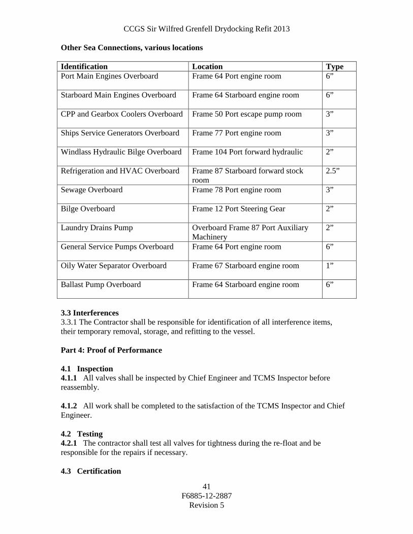
Other Sea Connections, various locations Identification Location Type Port Main Engines Overboard Frame 64 Port engine room 6”
Starboard Main Engines Overboard Frame 64 Starboard engine room 6”
CPP and Gearbox Coolers Overboard Frame 50 Port escape pump room 3”
Ships Service Generators Overboard Frame 77 Port engine room 3”
Windlass Hydraulic Bilge Overboard Frame 104 Port forward hydraulic 2”
Refrigeration and HVAC Overboard Frame 87 Starboard forward stock
room 2.5”
Sewage Overboard Frame 78 Port engine room 3”
Bilge Overboard Frame 12 Port Steering Gear 2”
Laundry Drains Pump Overboard Frame 87 Port Auxiliary Machinery
2”
General Service Pumps Overboard Frame 64 Port engine room 6”
Oily Water Separator Overboard Frame 67 Starboard engine room 1”
Ballast Pump Overboard Frame 64 Starboard engine room 6”
3.3 Interferences 3.3.1 The Contractor shall be responsible for identification of all interference items, their temporary removal, storage, and refitting to the vessel. Part 4: Proof of Performance 4.1 Inspection 4.1.1 All valves shall be inspected by Chief Engineer and TCMS Inspector before reassembly. 4.1.2 All work shall be completed to the satisfaction of the TCMS Inspector and Chief Engineer. 4.2 Testing 4.2.1 The contractor shall test all valves for tightness during the re-float and be responsible for the repairs if necessary. 4.3 Certification

CCGS Sir Wilfred Grenfell Drydocking Refit 2013
F6885-12-2887
Revision 5
42
4.3.1 If any machining is necessary or new valves required, the Contractor shall have full documentation of work performed and / or new valve certificates. Part 5: Deliverables: 5.1 Drawings/Reports 5.1.1. All reports from the work specified shall be given to the Chief Engineer. 5.1.2. Certificates for new valves shall be given to the Chief Engineer.

CCGS Sir Wilfred Grenfell Drydocking Refit 2013
F6885-12-2887
Revision 5
43
Spec item #: HD-11 SPECIFICATION TC Field #: 3L039
HD-11 Seabays, Seachests, Grids and Strainers Part 1: Scope: 1.1 The intent of this item is for the contractor to clean and paint the internal surfaces of the sea bay and the sea chests of the vessel, in preparation for replacement of the sacrificial anodes in these spaces. Description Size Port Sea Bay Frame 60-62 (Low) Approx Size 2m X 1m Stbd Sea Bay Frame60-62(High) Approx Size 2m X 1m Port Fi-Fi Sea Bay Frame 45-47 Approx Size 1m X 1m Stbd Fi-Fi Sea Bay Frame 46-47 Approx Size 1m X 1m Fwd Sea Bay Frame 96-97 Approx Size 0.5m X 1.5m Sea Chest Frame 60-62 Approx. Size 10m x 1.2m x 1m Port Sea Strainer Box Frame 60-62 Approx Size 0.5m x.0.5m x 0.75m Stbd Sea Strainer Box Frame 60-62 Approx Size 0.5m x.0.5m x 0.75m Part 2: References: 2.1 Guidance Drawings/Nameplate Data 2.1.1 SW Circulating Arrangement 2.2 Standards 2.2.1 Canadian Coast Guard Welding Specifications for Ferrous Materials, Revision 4. (TP6151 E). 2.3 Regulations 2.3.1 CSA Hull and Construction Regulation. 2.3.2 Ships ISM Safety Procedures. 2.4 Owner Furnished Equipment 2.4.1 The contractor shall supply all materials, equipment, parts and labor required to perform the specified work unless otherwise stated. Part 3: Technical Description: 3.1 General 3.1.1. Sea Bays 3.1.2. Each of the five (5) above sea bays shall have their strainer grids removed and the
grid holes cleaned as well as drilled or reamed as required to return them to their original size. These areas shall be hydro blasted, and inspected by the Chief Engineer. The sea chest and sea strainer boxes shall be dealt with in a different manner. Any areas where epoxy coating is found damaged shall be repaired as follows.

CCGS Sir Wilfred Grenfell Drydocking Refit 2013
F6885-12-2887
Revision 5
44
3.1.3. Surface Preparation 3.1.4. Abrasive Blast all bare and rusted areas to SSPC-SP-10 Near White Metal. All
edges of intact epoxy coating to be feather back to accept new coating. “Sweep Blast” the remaining area of intact coating to create a profile to accept new coating.
3.1.5. Primer - Touchup 3.1.6. Apply one touch up coat of Amercoat 238 Abrasion Resistant Epoxy to bare
blasted areas only. Apply @ 10 mils DFT. 3.1.7. Intermediate Coat 3.1.8. Apply one full coat of Amercoat 238 Abrasion Resistant Epoxy to entire area.
Apply @ 10 mils DFT. Colour Red Oxide. 3.1.9. Topcoat 3.1.10. Apply one full coat of Amercoat 339 Low Friction Hull Coating to entire area.
Apply @ 8 mils DFT. Colour Black. 3.1.11. The Contractor shall quote on repairing 20 square meters of the coating. Quote
shall include unit cost of each square meter and shall be used to adjust total area of damaged coating.
3.1.12. All anodes shall be replaced, as determined by the Owner’s Representative. The
seabays shall be closed up in good order with grids properly secured using stainless steel studs, Nuts and locking wire. The Port and Stbd Sea Strainer boxes shall be opened up for thorough cleaning of the internals and strainer grids. Strainers shall be re-installed and boxes closed up.
3.1.13. The Contractor shall quote a separate cost on removing a section of the bow and
stern thruster grids to gain access to the thruster tunnels for the replacement of the wasted anodes if required. The quote shall include the replacement of the sections and coating as per under water hull coating specifications.
3.1.14. It may be necessary to remove a section of 4 inch re-circulation line in the
starboard sea bay to gain access to seabay interior for cleaning and painting. This section of re-circulation line shall be replaced in good order upon completion of the work.
3.1.15. Sea Chest and Sea Strainer Boxes 3.1.16. The sea chest will be pumped down to suction level by the ship's engineers. The
manhole cover shall be removed, and any remaining water disposed of. The chest internals shall be wiped dry. A mechanical ventilation system vented to the outside of the ship shall be provided to ensure good air movement in the sea chest.
3.1.17. Flakes of rust scale or marine growth shall be scraped and wire brushed away
from chest internals. The internals shall be hydro-blasted clean. All debris shall be
CCGS Sir Wilfred Grenfell Drydocking Refit 2013
F6885-12-2887
Revision 5
45
removed ashore and the chest internals thoroughly dried out such that no moisture remains.
3.1.18. Upon completion of cleaning and prior to coating, the tank internals shall be
inspected by Owner's Representative and attending TCMS Surveyor. At this time wasted anodes shall be replaced as per zinc anode specification item.
3.1.19. Areas where epoxy coating is found damaged shall be dealt with as follows. 3.1.20. Surface Preparation 3.1.21. Power Tool Clean all bare/rusted areas to SSPC-SP-11 (power tool clean to bare
metal). Feather back all “intact” existing coating. 3.1.22. Coating System 3.1.23. Bare areas shall be coated with two (2) coats of Amercoat 235 Epoxy to bare
areas with sufficient feathering. Apply @ 5 to 6 mils Dry Film Thickness per coat. Total DFT shall be 10 to 12 mils. The contractor shall perform the work in accordance with product application instructions with particular attention to the environmental conditions.
3.1.24. The contractor shall quote on repairing 10 square metres of the coating and
include unit cost of each square meter which shall be used to adjust the total area of damaged coating.
3.1.25. The vents shall be proven clear and low level alarm tested. Upon completion the
sea chest shall be closed up in good order using new gasket material on the covers and anti-seizing compound on the fastener threads.
3.1.26. All work shall be to the satisfaction of the Chief Engineer and attending TCMS
Surveyor. Part 4: Proof of Performance 4.1 Inspection 4.1.1 All work shall be completed to the satisfaction of the Chief Engineer. 4.2 Testing 4.2.1 The contractor shall prove to the owners the DFT measurements at areas where the coating was completely missing. 4.3 Certification 4.3.1 The Contractor shall supply documentation of coatings applied. Part 5: Deliverables: 5.1 Drawings/Reports 5.1.1. The thickness determination DFT of the new coatings applied shall be verified
and recorded. Reports shall be given to Chief Engineer.

CCGS Sir Wilfred Grenfell Drydocking Refit 2013
F6885-12-2887
Revision 5
46
5.1.2. All reports from the work specified shall be given to the Chief Engineer. 5.1.3. The contractor shall supply copies of all paint coating MSDS and technical data
sheets.

CCGS Sir Wilfred Grenfell Drydocking Refit 2013
F6885-12-2887
Revision 5
47
Spec item #: HD-12 SPECIFICATION TCMSB Field #: N/A
HD-12 Water Ballast Tank Inspections and Cleaning Part 1: Scope: 1.1 The intent of this item shall be to have the following tanks opened up for cleaning abrasive blasting, coating repairs, inspection and hydrostatic pressure testing for TCMS and Chief Engineer 1.2 This work shall be carried out in Conjunction with the following: 1.2.1 HD-04 Hull Coating and Inspection Part 2: References: 2.1 Guidance Drawings/Nameplate Data 2.1.1 Shell Expansion. 2.1.2 Docking Plan. 2.1.3 Tank Capacity Plan. 2.1.4 Amercoat Product Data/Application Instructions. 2.2 Standards 2.2.1 Ships ISM Hot-Work, Confined Space, Fall Protection & Lockout Procedures. 2.2.2 Steel Structures Painting Council Standard (SSPC). 2.3 Regulations 2.3.1 CSA - Hull Construction Regulations. 2.4 Owner Furnished Equipment 2.4.1 The contractor shall supply all materials, equipment, labor and parts required to perform the specified work unless otherwise stated. Part 3: Technical Description: 3.1 General 3.1.1 The following tanks shall be opened up for cleaning, inspection by Transport Canada Marine Safety, abrasive blasting, coating repairs, and pressure testing. The Canadian Coast Guard will have a NACE inspector on site for the surface preparation and coating procedure.
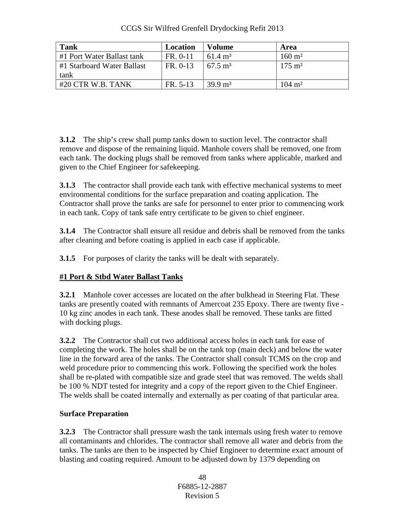
CCGS Sir Wilfred Grenfell Drydocking Refit 2013
F6885-12-2887
Revision 5
48
Tank Location Volume Area #1 Port Water Ballast tank FR. 0-11 61.4 m³ 160 m² #1 Starboard Water Ballast tank
FR. 0-13 67.5 m³ 175 m²
#20 CTR W.B. TANK FR. 5-13 39.9 m³ 104 m² 3.1.2 The ship’s crew shall pump tanks down to suction level. The contractor shall remove and dispose of the remaining liquid. Manhole covers shall be removed, one from each tank. The docking plugs shall be removed from tanks where applicable, marked and given to the Chief Engineer for safekeeping. 3.1.3 The contractor shall provide each tank with effective mechanical systems to meet environmental conditions for the surface preparation and coating application. The Contractor shall prove the tanks are safe for personnel to enter prior to commencing work in each tank. Copy of tank safe entry certificate to be given to chief engineer. 3.1.4 The Contractor shall ensure all residue and debris shall be removed from the tanks after cleaning and before coating is applied in each case if applicable. 3.1.5 For purposes of clarity the tanks will be dealt with separately. #1 Port & Stbd Water Ballast Tanks 3.2.1 Manhole cover accesses are located on the after bulkhead in Steering Flat. These tanks are presently coated with remnants of Amercoat 235 Epoxy. There are twenty five - 10 kg zinc anodes in each tank. These anodes shall be removed. These tanks are fitted with docking plugs. 3.2.2 The Contractor shall cut two additional access holes in each tank for ease of completing the work. The holes shall be on the tank top (main deck) and below the water line in the forward area of the tanks. The Contractor shall consult TCMS on the crop and weld procedure prior to commencing this work. Following the specified work the holes shall be re-plated with compatible size and grade steel that was removed. The welds shall be 100 % NDT tested for integrity and a copy of the report given to the Chief Engineer. The welds shall be coated internally and externally as per coating of that particular area. Surface Preparation 3.2.3 The Contractor shall pressure wash the tank internals using fresh water to remove all contaminants and chlorides. The contractor shall remove all water and debris from the tanks. The tanks are then to be inspected by Chief Engineer to determine exact amount of blasting and coating required. Amount to be adjusted down by 1379 depending on

CCGS Sir Wilfred Grenfell Drydocking Refit 2013
F6885-12-2887
Revision 5
49
coating condition. Note: Contractor to quote on water, grit blasting and coating of entire tank surface area. 3.2.4 The contractor shall Abrasive Blast the required internal surfaces to SSPC-SP-10 Near White Metal to achieve an anchor profile of 2.0 to 3.0 mils. The contractor shall remove all debris from the tanks prior to coating. 3.2.5 The contractor shall then have the tank internally inspected by TCMS and the Chief Engineer. Coating System Inspection and Testing 3.2.6 The contractor shall apply two (2) full coats of Amercoat 235 Epoxy to the required tank surface. Apply @ 5 to 6 mils Dry Film Thickness per coat. Total DFT shall be 10 to 12 mils feathered to remaining good coating as required. The contractor shall perform the work in accordance with product application instructions with particular attention to the environmental conditions. 3.2.7 Following the coating and recommended drying time the contractor to inform Chief Engineer for an inspection of tank. Upon approval from Chief Engineer the contractor shall perform hydrostatic test on the tanks. The vent heads shall be removed for this procedure and replaced when completed with new ¼” neoprene gasket. Tank vent shall be inspected for foreign debris prior to installation. Tank covers are to have new ¼” neoprene gaskets installed. TCMS shall witness the test. It is the Contractor’s responsibility to notify TCMS. Note: Contractor to include in bid the cost of replacing 20 cover studs and nuts to be adjusted up or down by 1379 action. # 20 C Water Ballast Tank 3.3.1 Manhole cover is located port of center in Steering Flat Deck. This tank is coated with Amercoat 235. Tank is fitted with a docking plug. 3.3.2 The intent for this tank shall be to water blast the entire tank for inspection, abrasive blast and coat tank as required. Surface Preparation 3.3.5 The contractor shall Pressure Wash the tank internals using fresh water to remove all contaminants and chlorides. All water and debris is to be removed ashore and the tank inspected by Chief Engineer to determine exact amount of blast and coating required. Amount to be adjusted down by 1379 depending on coating condition. Note: Contractor to quote on pressure washing entire tank surface area and grit blasting and coating of 10% tank surface area.

CCGS Sir Wilfred Grenfell Drydocking Refit 2013
F6885-12-2887
Revision 5
50
3.3.6 The contractor shall Abrasive Blast the damaged areas to SSPC-SP-10 Near White Metal to achieve an anchor profile of 2.0 to 3.0 mils feathering to existing good coating surfaces. The contractor shall remove all debris from the tanks prior to coating. 3.3.7 The contractor shall then have the tank internally inspected by TCMS and the Chief Engineer. Coating System Inspection and Testing 3.3.8 The contractor shall apply two (2) full coats of Amercoat 235 Epoxy to effected tank surface. Apply @ 5 to 6 mils Dry Film Thickness per coat. Total DFT shall be 10 to 12 mils. The contractor shall perform the work in accordance with product application instructions with particular attention to the environmental conditions. 3.3.9 Following the coating and curing time the Contractor shall notify the Chief engineer to inspect the tank. Upon approval from Chief Engineer the contractor is to button up tank and perform hydrostatic test on the tanks. Tank covers are to have new ¼” neoprene gaskets installed. The vent heads shall be removed for this procedure and replaced when completed with new ¼” neoprene gasket. Tank vent shall be inspected for foreign debris prior to installation. TCMS shall witness the test. It is the Contractor’s responsibility to notify TCMS. Note: Contractor to include in bid the cost of replacing 20 cover studs and nuts to be adjusted up or down by 1379 action. Part 4: Proof of Performance 4.1 Inspection 4.1.1 All work shall be completed to the satisfaction of the Chief Engineer, TCMS and NACE Inspector. 4.1.2 Tank vents shall be inspected for foreign debris prior to installation. 4.2 Testing 4.2.1 The Contractor shall prove to the owners the DFT measurements at areas where the coating was completely missing. 4.2.2 The Contractor shall perform hydrostatic test on the tanks to be witnessed by TCMS and Chief Engineer. 4.3 Certification 4.3.1 The Contractor shall supply documentation of coating applied. Part 5: Deliverables: 5.1 Drawings/Reports 5.1.1 The thickness determination DFT of the new coatings applied shall be verified and recorded. Reports shall be given to Chief Engineer.

CCGS Sir Wilfred Grenfell Drydocking Refit 2013
F6885-12-2887
Revision 5
51
5.1.2 All reports from the work specified shall be given to the Chief Engineer. 5.1.3 The contractor shall supply copies of all paint coating MSDS and technical data sheets.

CCGS Sir Wilfred Grenfell Drydocking Refit 2013
F6885-12-2887
Revision 5
52
Item #: H-01 SPECIFICATION TC Field #: 3N0090
H-01 Fixed Firefighting Systems Part 1: Scope: 1.1 The intent shall be to test and inspect the vessel’s FM-200 Fixed Fire Fighting Systems for TCMS annual requirements. All tests shall be witnessed by the Chief Engineer and the attending TCMS Surveyor. 1.2 The contractor shall obtain the services of an Authorized Representative for all systems. Part 2: References: 2.1 Guidance Drawings/Nameplate Data 2.1.1 N/A 2.2 Standards 2.2.1 Coast Guards ISM Lockout, Hotwork, Confined Space Entry, Lockout, and Fall Protection procedures are to be strictly enforced. 2.2.2 Contractor to have the necessary qualification and Manufacturer’s approval to work on the new FM200 systems. 2.3 Regulations 2.3.1 Canada Shipping act. 2.3.2 TCMS Annual Inspections. 2.4 Owner Furnished Equipment 2.4.1 The contractor shall supply all materials, equipment, parts and labor required to perform the specified work unless otherwise stated. Part 3: Technical Description: 3.1 General 3.1.1 Before any work is to commence the contractor shall meet with the ships Electrical Officer and Chief Engineer for identification and Lockout of all FM200 system power isolation switches, and to inform ships personnel that these systems will be worked on and will be un-operational. 3.1.2 The Level and Contents of each cylinder shall be ascertained, recorded and given

CCGS Sir Wilfred Grenfell Drydocking Refit 2013
F6885-12-2887
Revision 5
53
to the Chief Engineer. 3.1.2.1 Main Engine Room Port and Starboard Systems Located in foam room Four (4) FM200 600 lbs. Eight (8) Nitrogen Driver Cylinders Four (4) Activation / Control Nitrogen Cylinders 3.1.2.2 Port and Starboard Engine Room Bilge System Located in Lower engine Room: Two (2) FM200 Cylinders 176 lbs Two (2) Nitrogen Driver Cylinders 3.1.2.3 Pump Room FM200 System Located in Foam Room One (1) FM200 Cylinder 225 Lbs Three (3) Activation / Control Nitrogen Cylinders 3.1.2.4 Stern Thruster and Steering Gear System: Located In Lathe Room One (1) FM200 Cylinder 197 lbs. Three (3) Activation / Control Nitrogen Cylinders 3.1.2.5 Auxiliary Machinery Space: Located Alleyway Outside Space One (1) FM200 Cylinder 109 Lbs, Three (3) Activation / Control Nitrogen Cylinders 3.1.2.6 Bowthruster Compartment: Located Outside Space Tank Top One (1) FM200 Cylinder 122 Lbs. Three (3) Activation Control Nitrogen Cylinders 3.1.2.7 Paint Locker: Located In Paint Locker One (1) FM200 Cylinder 48 Lbs Four (4) Activation / Control Nitrogen Cylinders in the HVAC Room 3.1.2.8 Emergency Generator Room Located In Emergency Generator Room One (1) FM200 Cylinder 25 Lbs Four (4) Activation / Control Nitrogen Cylinders in the Protected Space 3.1.2.9 Electronics Room FM200 Located in Electronics Room One (1) FM200 Cylinder 123 Lbs Four (4) Activation / Control Nitrogen Cylinders in the Protected Space

CCGS Sir Wilfred Grenfell Drydocking Refit 2013
F6885-12-2887
Revision 5
54
3.1.2.10 Gun Locker Fitted With CO2 - One 20 Lb Cylinder. 3.1.3 The FM200 cylinders and CO2 shall be disconnected as per the manufacturer’s recommendations and instructions, after advising Chief Engineer, FM200 heads removed and all associated piping shall be blown through to prove all lines are clear. All controls, electrical and mechanical, including sirens and ventilation shutdowns shall be proven operational. 3.1.4 Upon completion of all work, all systems shall be reconnected in good working order. 3.1.5 Any recharging shall be carried out under PWGSC 1379 action. 3.1.6 Copies of test certificates shall be forwarded to Chief Engineer. 3.1.7 Twin-Agent Fire Extinguishing Skid Unit: FOAM BOSS Model: 1013-87 Hose: 98.5 x 1" twin jacketed Dry chemical vessel: 500 pound capacity AFFF vessel: 100 USG capacity. Pre-mixed 3% solution Nitrogen cylinders: 2x300 cubic feet 3.1.7.1 The twin-agent skid unit shall be thoroughly examined and tested as per TCMS requirements. The level and contents of both nitrogen cylinders shall be ascertained. Each nitrogen regulator shall be examined for defects and proven to operate correctly. The pressure regulator should give a nominal downstream pressure of 230-250 psi. 3.1.7.2 The contents of the dry chemical system shall be checked for the powder having "caked" or "compacted" and a sample given to the Chief Engineer. All linkages and cabling shall be cleaned and proven free to operate properly. All associated piping including the twin-jacketed hose shall be proven clear. 3.1.7.3 The safety relief valve shall be inspected for defects and tested to the lift setting of 250 psi. 3.1.7.4 The hand nozzle valve shall be inspected for defects and checked for correct operation. 3.1.7.5 The Hose shall be completely rolled out and inspected, then the hose shall be properly pressure tested and certificate of the testing given to Chief Engineer. This is a requirement for our ISM tracking system.
CCGS Sir Wilfred Grenfell Drydocking Refit 2013
F6885-12-2887
Revision 5
55
3.1.7.6 Upon completion of all work, the system shall be reassembled in good order to an operational state. 3.1.7.7 The Pre-mix foam solution in the Twin Skid system was renewed Refit 2006. 3.1.7.8 Foam samples shall be taken from Twin Agent system and from helicopter firefighting 6000 litre foam tank. Sample strengths to be tested and copies of results given to Chief Engineer. 3.1.8 Helicopter Foam System: 3.1.8.1 The proportional valve arrangement and diaphragm shall be opened up for inspection and re-assembled. 3.1.9 Shipboard Fire Fighting Foam Supply (20 Litre Containers). 3.1.9.1 Foam samples shall be taken from 20 litre containers of 3% AFFF stored in Emergency Equipment Locker. Sample required from each batch lot, presently only 1 batch lot onboard. Sample strengths to be tested and copies of results given to Chief Officer. (As per Fleet Bulletin 06-2007) 3.1.10 Galley Range Karbaloy Fire Extinguishing System: 3.1.10.1 The contractor shall provide the services of an Authorized "Range Guard" Representative to perform the following work. 3.1.10.2 Disconnect the Karbaloy cylinder. 3.1.10.3 Clean linkages and cabling. 3.1.10.4 Prove the associated piping is clear. 3.1.10.5 Pressure switches, hand controls and electrical shutdowns shall be proven operational with tests being witnessed by Chief Engineer and attending TCMS Surveyor. 3.1.10.6 Contents of cylinder to be ascertained and recorded. 3.1.10.7 Upon completion of all of the above, the system shall be reconnected in good working order to an operational state. Copies of the test certificates to be forwarded to Chief Engineer. 3.1.10.8 All work shall be done to the satisfaction of the TCMS Inspector and the Chief Engineer. 3.2 Location 3.2.1 FM200 systems: Foam room,
Engine room, Stern Thruster/Steering Gear Compartments, Paint Locker,

CCGS Sir Wilfred Grenfell Drydocking Refit 2013
F6885-12-2887
Revision 5
56
Auxiliary Machinery room Bow Thruster Compartment
Emergency generator room Electronics Room
3.2.2 CO2 System in Gun Locker :
Foc’sle deck aft 3.2.3 Galley Karbaloy System:
Crews Mess, Room Foc’sle deck. 3.3 Interferences 3.3.1 The Contractor is responsible for identification of interference items, their temporary removal, storage, and refitting to the vessel. Part 4: Proof of Performance 4.1 Inspection 4.1.1 All work shall be completed to the satisfaction of TCMS and the Chief Engineer. 4.2 Testing 4.2.1 As per specification. 4.3 Certification 4.3.1 All certificates shall be given to Chief Engineer. Part 5: Deliverables: 5.1 Drawings/Reports 5.1.1 All certificates shall be given to Chief Engineer. 5.1.2 All reports from the work specified shall be given to the Chief Engineer. 5.2 Spares 5.2.1 N/A. 5.3 Training 5.3.1 N/A. 5.4 Manuals 5.4.1 N/A

CCGS Sir Wilfred Grenfell Drydocking Refit 2013
F6885-12-2887
Revision 5
57
Part 1: Scope: 1.1 The intent of this item shall be to clean the galley exhaust ventilation of build up of grease and for the prevention of possible fires. Part 2: References: 2.1 Guidance Drawings/Nameplate Data 2.1.1 N/A 2.2 Standards 2.2.1 Coast Guards ISM hotwork, Confined Space entry, and fall protection procedures are to be strictly enforced. 2.3 Regulations 2.3.1 CSA - Fire Regulations. 2.4 Owner Furnished Equipment 2.4.1 The contractor shall supply all materials, equipment, labor and parts required to perform the specified work unless otherwise stated. Part 3: Technical Description: 3.1 General 3.1.1 Trunking Length is 30 feet of 18 inches x 8 inches rectangular duct. 3.1.2 The contractor shall dismount and clean the galley range exhaust fan and use the access so created to mechanically and chemically clean the trunking. A portion of the trunking can be disconnected at the lower Bridge Deck exterior to assist in the cleaning. 3.1.3 The Contractor supplied chemicals used shall be non-flammable and low vapour. The galley surfaces shall be protected from residues, run-offs and debris. All residues and debris shall be removed ashore by the contractor. The exhaust fan shall be remounted on completion of satisfactory inspection of the trunking by the Chief Engineer. 3.1.4 The contractor shall note that the vessel will be crewed and the galley in use during the time this work will be performed. The work shall take place outside of normal galley hours that are 0600 – 1800 hours daily. The galley shall be left in a clean and tidy condition for 0600 each day with any materials and debris removed. 3.1.5 On completion of work, contractor shall ensure all areas/equipment affected by the work to be clean of dust and residues, and that all fittings removed are re- installed in there original positions. 3.1.6 All work shall be to the satisfaction of the Chief Engineer. 3.2 Location 3.2.1 Galley Port Aft 3.2.2 Lower Bridge Deck 3.3 Interferences 3.3.1 The contractor will be responsible for all removals required for completion of this item. Any removals shall be replaced in good order after the completion of all work.
Spec item #: H-02 SPECIFICATION TCMS Field #: N/A
H-02 Galley Exhaust Fan Trunking Cleaning

CCGS Sir Wilfred Grenfell Drydocking Refit 2013
F6885-12-2887
Revision 5
58
3.3.2 Work is to be arranged with Chief Engineer, so it will have the least interference on the Contractor or Crew especially the Galley crew. 3.3.3 The Contractor is responsible for the identification of all interference items, their temporary removal, storage, and refitting to vessel. Part 4: Proof of Performance 4.1 Inspection 4.1.1 The Chief Engineer shall check cleanliness of the Duct before it is boxed up. 4.1.2 All work shall be completed to the satisfaction of the Chief Engineer. 4.2 Testing 4.2.1 After completion of work, the system shall be started up with Chief Engineer present, motor to be turning properly etc. 4.3 Certification 4.3.1 All reports from the work specified shall be Given to the Chief Engineer. Part 5: Deliverables: 5.1 Drawings/Reports 5.1.1 All reports from the work specified shall be given to the Chief Engineer. 5.2 Spares 5.2.1 N/A 5.3 Training 5.3.1 N/A 5.4 Manuals 5.4.1 N/A.

CCGS Sir Wilfred Grenfell Drydocking Refit 2013
F6885-12-2887
Revision 5
59
Part 1: Scope: 1.1 The intent of this item shall be to clean the HVAC ducting and registers and diffusers as required for health reasons. 1.2 Before the Contractor commences any work, the HVAC refrigeration compressors and the fans for the spaces are to be locked out, and entered in Ships Lockout procedures Log book. 1.3 This work shall be carried out in Conjunction with: N/A Part 2: References: 2.1 Guidance Drawings/Nameplate Data 2.1.1 HVAC Drawing: NJC - 70 - 200 2.2 Standards 2.2.1 Coast Guards ISM hotwork, Confined Space entry, Lockout, and fall protection procedures are to be strictly enforced. 2.2.2 A valid hotwork permit must be obtained from vessel’s Chief Engineer before any type of hot work is performed. 2.3 Regulations 2.3.1 N/A 2.4 Owner Furnished Equipment 2.4.1 The contractor shall supply all materials, equipment, labour and parts required to perform the specified work unless otherwise stated. Part 3: Technical Description: 3.1 General 3.1.1 The Contractor shall mechanically clean the accommodation space ventilation trunking and remove all debris ashore as per generally accepted industry practice. The trunking to be cleaned is all that HVAC systems supply to all cabins, common spaces, galley, and storerooms. The deckhead diffusers shall be taken down in each compartment and the trunking cleaned as far as practical and the diffusers replaced in good order 3.1.2 The Contractor shall supply and install a protective covering over furniture and all outfit in all cabins where this work is performed. 3.1.3 Total amount of registers/diffusers = 64 as per the following cabin and compartments:
Spec item #: H-03 SPECIFICATION TCMSB Field #: N/A
H-03 Accommodation Space Ventilation Trunking Cleaning

CCGS Sir Wilfred Grenfell Drydocking Refit 2013
F6885-12-2887
Revision 5
60
Bridge Boat Deck Foc’sle Deck Main deck
Bridge = 12 Captain’s Cabin = 2 C/E’s Cabin = 2 Chief Officer’s cabin = 1 Sen. Engineer’s cabin =1 B/D by Sr engr. cabin = 1 Elect. officer’s cabin = 1 Sec. Engineer’s cabin = 1 Third engineer’s cabin = 1 Second officer’s cabin = 1
Fisheries officer port = 1 Fisheries officer starboard =1 Officer’s lounge = 2 Galley = 3 Off. Mess = 2 Crew lounge = 2 Crew Mess = 2 Starboard Foc’sle deck aft = 1
Oiler =1 Oiler = 1 Port Main deck aft = 1 Hospital,triage & ships office = 9 Oiler = 1 Steward = 1 Store keeper = 1 Cook = 1 Bosun = 1 Leading Seaman = 1 Leading Seaman = 1 Leading Seaman = 1 Starboard main deck = 1 Starboard main deck By stairs = 1 Seaman = 1 Seaman = 1 LAN room = 1 Female washroom = 1 Laundry Room in staircase area = 1
3.1.3 All Materials used shall be to the most recent standards of that used for Air Duct Cleaning. 3.1.4 After completion of work, the Contactor shall ensure all areas/equipment affected by the work shall be cleaned of dust and residues. All the protective coverings shall be removed. 3.2 Location 3.2.1 Accommodation ducting is found on the following decks; Bridge Deck Lower Bridge Deck Boat Deck Forecastle Deck Main Deck Below Main Deck 3.3 Interferences 3.3.1 The Contractor shall be responsible for identification of all interference items,

CCGS Sir Wilfred Grenfell Drydocking Refit 2013
F6885-12-2887
Revision 5
61
their temporary removal, storage, and refitting to the vessel. Part 4: Proof of Performance 4.1 Inspection 4.1.1 All work shall be completed to the satisfaction of the Chief Engineer. 4.2 Testing 4.2.1 Upon completion of all work, the contractor shall test the system by operating all the ventilation fans. 4.2.2 The Contractor and Chief Engineer to check for air leakage through duct joints and Plenum doors. Etc. 4.3 Certification 4.3.1 The contractor shall obtain and provide documentation to the Chief Engineer all required technical certification as specified in the applicable rules and codes. 4.3.2 Equipment and component inspection certificates including all test reports supporting the certifications shall be given to the Chief Engineer. 4.3.3 Copies of MSDS of any chemicals used for the work shall be given to the Chief Officer. Part 5: Deliverables: 5.1 Drawings/Reports 5.1.1 Equipment and component inspection certificates including all test reports supporting the certifications shall be given to the Chief Engineer. 5.2 Spares 5.2.1 N/A 5.3 Training 5.3.1 N/A 5.4 Manuals 5.4.1 N/A

CCGS Sir Wilfred Grenfell Drydocking Refit 2013
F6885-12-2887
Revision 5
62
Spec item#: H-04 SPECIFICATION TCMS Field #:
H-04 Fuel Oil, Lube Oil and Waste Tank Cleaning and Inspection Part 1: Scope: 1.1 The intent of this item shall be to clean, inspect and pressure test the following tanks
for TCMS survey. 1.2 This work shall be carried out in conjunction with the following: 1.2.1. L-01 Kongsberg Tank Level Transducers
Part 2: References: 2.1 Guidance Drawings/Nameplate Data TANK LOCATION CAPACITY
m³ TCMS #
#9 Port Fuel FR. 43-60 93.5 3L017 #9 Stbd Fuel FR 43-60 89.3 3L018 #14 Port Fuel FR. 68-82 26.0 3L025 #14 Stbd Fuel FR. 68-82 26.0 3L026 Sludge Tank FR. 43-47 11.18 3L035 Dirty Oil Tank FR 50-54 7.58 3L036 Bilge Collection Tank FR. 64-66 4.20 3L037 Main Engine Lube Oil Tk FR. 62-66 12.65 3L038 Fuel Oil Drains Tank FR. 47-50 5.62 3L043 Gear Oil Tk Port FR. 48-50 4.26 3L045 CCP Oil Tank Port FR. 50-52 4.26 3L043 Part 3: Technical Description: 3.1.1. Ship’s personnel shall pump/drain the tanks to suction level. 3.1.2. The contractor shall dispose of any remaining fuel or sludge ashore. Quote on
removal of 1000 litres per tank; to be adjusted up or down as required by 1379. 3.1.3. Tanks shall be certified gas free and safe for men to enter, by a certified chemist.
One copy of each gas free certificate shall be posted outside of subject tank, near manhole, and one copy of each certificate shall be given to the Chief Engineer prior to men entering the tank. Each tank interior is then to be washed with high pressure water/degreaser mixture, and remnants disposed of. Tanks are then to be wiped dry.

CCGS Sir Wilfred Grenfell Drydocking Refit 2013
F6885-12-2887
Revision 5
63
3.1.4. Tank internals are then to be inspected by the Chief Engineer and attending TCMS Surveyor.
3.1.5. Tank vent heads shall be removed (one per tank) to prepare for an air test using a
manometer on each tank. Each tank shall then be air tested to the satisfaction of attending TCMS surveyor.
3.1.6. Upon completion each tank shall be drained and internals wiped dry. Owner’s
representative shall inspect each tank prior to final closing. Vent pipe valve bodies shall be replaced using new gaskets. Manhole covers and docking plugs shall be replaced as per original using new ¼” neoprene gaskets on manholes.
3.1.7. The contractor shall supply all material to perform the specified work. Part 4: Proof of Performance 4.1 Inspection 4.1.1 All work shall be completed to the satisfaction of the Chief Engineer. 4.2 Testing Each tank shall then be air tested to the satisfaction of attending TCMS surveyor 4.3 Certification 4.3.1 The contractor shall obtain and provide documentation to the Chief Engineer all required technical certification as specified in the applicable rules and codes. 4.3.2 Equipment and component inspection certificates including all test reports supporting the certifications shall be given to the Chief Engineer. Part 5: Deliverables: 5.1 Drawings/Reports 5.1.1 Equipment and component inspection certificates including all test reports supporting the certifications shall be given to the Chief Engineer. 5.2 Spares 5.2.1 N/A 5.3 Training 5.3.1 N/A 5.4 Manuals 5.4.1 N/A

CCGS Sir Wilfred Grenfell Drydocking Refit 2013
F6885-12-2887
Revision 5
64
Item #: H-05 SPECIFICATION TCMS Field #: N/A
H-05 Annual Inspections, Port and Starboard Miranda Davits
Part 1: Scope:
1.1 The intent of this specification shall be for the contractor to supply the services of a Schat Harding Representative to carry out annual inspection on the vessel’s Miranda Davits.
1.2 The contractor shall include in his quote $8000.00 for the services of the FSR.
1.3 This allowance encompasses FSR services for H-05 and H-06. The Contractor shall allow one labourer for forty hours to assist the Schat FSR for work encompassed in H-05 and H-06.
1.4 This work shall be carried out in conjunction with the following: 1.4.1. H-06 Annual Inspections, Lifeboat and Davit Part 2: References: 2.1 Guidance Drawings/Nameplate Data 2.2 Standards 2.3 Regulations 2.3.1 N/A 2.4 Owner Furnished Equipment 2.4.1 The contractor shall supply all materials, equipment, labour and parts required to perform the specified work unless otherwise stated. Part 3: Technical Description:
3.1 General
3.1.1. The contractor shall supply the services of a Schat Harding representative to carry out an annual inspection on the Miranda Davits in accordance with Schat Harding procedures and checklists. Summary inspection of key components to be carried out as quickly as possible to identify critical path, and possible purchase of long-lead items.
3.1.2. 3.1.3. Contact information for the FSR:
Colin Edwards, Manager, Umoe Schat Harding, tel: 604-543-0849 3.1.4. The intention is for the FSR to Assist Ships Crew in the carrying out of the
inspection.

CCGS Sir Wilfred Grenfell Drydocking Refit 2013
F6885-12-2887
Revision 5
65
3.2 Location The Miranda Davits are located on the port and starboard side of the foc’sle deck.
3.3 Interferences
Contractor is responsible for the identification of interference items, their temporary removal, storage and refitting to vessel. Part 4: Proof of Performance
4.1 Inspection All work shall be completed to the satisfaction of the Chief Engineer.
4.2 Testing
Davits are to be functionally tested in accordance with Schat Harding procedures and checklists. 4.3 Certification 4.3.1. Instruments or accessories required to perform testing of davits shall be certified and calibrated (i.e. loads cell or stones used to test davit structure) Part 5: Deliverables:
5.1 Drawings/Reports
5.1.1 The contractor shall arrange for the Schat Harding FSR to shall provide three typewritten reports detailing the inspections and his findings to the Chief Engineer.
5.2 Spares
5.3 Training
5.4 Manuals
CCGS Sir Wilfred Grenfell Drydocking Refit 2013
F6885-12-2887
Revision 5
66
Item #: H-06 SPECIFICATION TCMSB Field #: N/A
H-06 Annual Inspections, Lifeboat and Davit
Part 1: Scope:
1.1 The intent of this specification shall be for the contractor to supply the services of a Schat Harding Representative to carry out annual inspection on the vessel’s Lifeboat and Lifeboat Davit in accordance with Schat Harding procedures and checklists.
1.2 This work shall be carried out in conjunction with the following: H-05 Annual Inspections, Port and Starboard Miranda Davits Part 2: References: 2.1 Guidance Drawings/Nameplate Data 2.2 Standards 2.3 Regulations 2.3.1 N/A 2.4 Owner Furnished Equipment 2.4.1 The contractor shall supply all materials, equipment, labour and parts required to perform the specified work unless otherwise stated. Part 3: Technical Description: 3.1 General
3.1.1. The contractor shall supply the services of a Schat Harding representative to carry
out an annual inspection on the Lifeboat and Davit in accordance with Schat Harding procedures and checklists. Summary inspection of key components to be carried out as quickly as possible to identify critical path, and possible purchase of long-lead items.
3.1.2. Contact information for the FSR: Colin Edwards, Manager, Umoe Schat Harding, tel: 604-543-0849
CCGS Sir Wilfred Grenfell Drydocking Refit 2013
F6885-12-2887
Revision 5
67
3.1.3. The intention is for the FSR to assist Ships Crew in the carrying out of the inspection.
3.2 Location
3.2.1. The Lifeboat and Davit are located on the starboard side of the boat deck.
3.3 Interferences
3.3.1. Contractor is responsible for the identification of interference items, their temporary removal, storage and refitting to vessel.
Part 4: Proof of Performance 4.2 Inspection 4.1.1. All work shall be completed to the satisfaction of the Chief Engineer. 4.3 Testing
4.2.1. Davits are to be functionally tested in accordance with Schat Harding procedures and checklists.
4.3 Certification 4.3.1. Instruments or accessories required to perform testing of davits shall be certified and calibrated (i.e. loads cell or stones used to test davit structure) Part 5: Deliverables:
5.1 Drawings/Reports
5.1.1 The contractor shall arrange for the Schat Harding FSR to shall provide three typewritten reports detailing the inspections and his findings to the Chief Engineer.
5.2 Spares
5.3 Training
5.4 Manuals

CCGS Sir Wilfred Grenfell Drydocking Refit 2013
F6885-12-2887
Revision 5
68
Spec item #: H-07 SPECIFICATION TCMSB Field #:
H-07 Life Rafts Certification Part 1: Scope: 1.1 The intent of this specification shall be for the contractor to provide the services
of a qualified contractor to inspect and certify the life rafts on the vessel. Part 2: References: 2.1 Guidance Drawings/Nameplate Data
2.2 Standards 2.3 Regulations
2.4 Owner Furnished Equipment
2.4.1. The contractor shall supply all materials, equipment, and parts required to
perform the specified work unless otherwise stated. Part 3: Technical Description: 3.1 General
3.1.1. There are six (6) 16 person life rafts on the vessel manufactured by RFD. 3.1.2. The contractor shall remove the rafts from the vessel and transport to the sub-
contractor’s facility for inspection and certification of the life rafts. 3.1.3. The sub-contractor shall be certified to carry out inspection for the make of the
life rafts. The subcontractor shall be responsible for contacting TCMS. 3.1.4. Upon completion of the rafts they shall be returned to the vessel and installed in
the proper locations as directed by the Chief Officer. Certificates are to be delivered to the Chief Officer. The contractor is responsible for transport to/from the ship and delivery of the certificates to the Chief Officer, the invoices shall be paid by CCG Marine Engineering.

CCGS Sir Wilfred Grenfell Drydocking Refit 2013
F6885-12-2887
Revision 5
69
3.2 Location
3.2.1. Three on port bridge deck, three on starboard bridge deck.
3.3 Interferences
3.3.1. Contractor is responsible for the identification of interference items, their temporary removal, storage and refitting to vessel.
Part 4: PROOF OF PERFORMANCE: 4.1 Inspection
4.1.1. All work shall be completed to the satisfaction of the Chief Engineer. 4.2 Testing
4.3 Certification Part 5: DELIVERABLES: 5.1 Drawings/Reports
5.1.1 The contractor shall provide a report detailing the work carried out and items replaced. The contractor shall provide the updated liferaft certificates to the Chief Officer.
5.2 Spares
5.3 Training
5.4 Manuals

CCGS Sir Wilfred Grenfell Drydocking Refit 2013
F6885-12-2887
Revision 5
70
Spec item #: H-08 SPECIFICATION TCMSB Field #:
H-08 Female Washroom Repairs
Part 1: Scope: 1.1 The intent of this specification is to outline the work required in restoring the
Crew’s Female Washroom to a sanitary and aesthetic condition.
1.2 The refurbishment will consist of upgrade to the toilet and shower stalls
Part 2: References: 2.1 Guidance Drawings/Nameplate Data General Arrangement NJC-10-100 2.2 Standards 2.2.1 Canadian Coast Guard Fleet Safety Manual (DFO 5737) 2.2.2 Coast Guard ISM Confined Space Entry 7.D.9 2.2.3 ISM hotwork, Confined Space entry, and fall protection procedures are to be
strictly enforced. 2.2.4 All welding shall be as per specification preamble. 2.2.5 CG Lockout Procedure. 2.3 Regulations 2.4 Owner Furnished Equipment 2.4.1 The contractor shall supply all materials, equipment, labor and parts required to perform the specified work unless otherwise stated. Part 3: Technical Description: 3.1 General
Shower Stalls
3.1.1. The washroom consists of two shower stalls; each stall has a showering section

CCGS Sir Wilfred Grenfell Drydocking Refit 2013
F6885-12-2887
Revision 5
71
and a change area. 3.1.2. The Contractor shall isolate and remove hot and cold water lines, shower mixing
valves, and shower partitions.
3.1.3. New fiberglass enclosures shall be fabricated and installed. The Contractor shall use the services of a professional bath fitting service to fabricate and install the new enclosures. Each new enclosure shall include the showering area and change area. In order to allow for the installation of new enclosures the existing corrugations in the bulkheads in the showering area will have to be cut out and flat plate of the existing thickness will be inserted and welded in place. The enclosures shall extend up to a minimum of 8 inches below the existing deckhead panels. The Contractor will consult with the Chief Engineer and bath fitter to determine the height of the inserts. It will be required to weld rounded inserts at 90 degrees at the top of the inserts to form a transition to the remaining section of corrugation at the top of the shower.
3.1.4. All penetrations for pipe work and drains of the new enclosures shall be covered
with decorative flanges. All open edges shall be fitted with decorative trim or molded round. Each enclosure shall be fitted with new handrails, soap dishes, and toiletry holders. The change areas shall be fitted with clothes hooks. All fastenings shall be decorative stainless steel screws.
3.1.5. The Contractor shall supply and install 2 new 120 Volt heat lamps and all material
necessary, (1 each) shall be installed in the change areas with the switch located outside the shower area. Switches shall be fitted with timers to allow turning off after a one hour period. Appropriate electrical cabling shall be supplied and installed, the Contractor to allow for 50 feet for bid purposes. The Contractor shall install a junction box in deckhead near panel L-04 in Port Alleyway. Connection of wiring will be to Breaker L-4-17. This will involve pulling back existing wiring to new junction box and fitting a new cable run to Junction box from Panel as well from junction box to new heat lamps. All interference Items shall be removed and reinstalled by the Contractor. Note that one 5x12” vent will have to be relocated forward approx. 1 Ft.
3.1.6. Shower control valves and piping shall be concealed in a stainless steel enclosure
similar to the Male Washroom. 3.1.7. All piping and valves shall be re-connected. New shower control valves shall be
installed; these shall be Crane Rada Excel Series Valve to maintain inventory consistency.
3.1.8. Contractor shall use the Male Washroom design to maintain continuity in
appearance.
Toilets
CCGS Sir Wilfred Grenfell Drydocking Refit 2013
F6885-12-2887
Revision 5
72
3.1.1. Washroom consists of two toilet stalls, each fitted with a toilet, handrail, and paper holder.
3.1.2. Toilets shall be removed from the seating, new style toilet shall be reused and the
old style toilet shall be discarded and a new owner supplied toilet shall be installed. The wooden toilet seating and studs shall be removed from the deck. The deck shall be cleaned to bare metal. New studs and wooden seat shall be fabricated the same shape and size of the toilets bottom seating that will be installed. The wood shall be fastened with studs welded to the deck and countersunk nuts. Four additional studs shall be installed for fastening the toilet. All studs shall be stainless steel. The wood shall be oak at a thickness that suits the standard toilet height from the finished deck. Allow 2 inches thick, 18 inches deep, and 12 wide for bidding purposes. The toilets shall be installed; some minor rework of ABS pipe in the toilet area will be required.
3.1.3. Contractor shall remove existing toilet partitions, doors, and replace with new
partitions and doors the same as existing. Toilet stalls shall be fitted with a privacy lock that is actuated from the inside, a latch arrangement on the outside to prevent door from swinging while at sea, new stainless steel hand rails, and paper holders. This shall be completed prior to installing new deck coverings.
3.1.4. All work and materials shall be to the satisfaction of Chief Engineer.
3.1.5. The Contractor shall dispose of the removals to the contractor’s facilities.
3.2 Location Starboard Raised Main Deck Forward. 3.3 Interferences 3.3.1. The Contractor shall be responsible for the identification of all interference items,
their temporary removal, and storage and refitting to vessel.
3.3.2. Affected areas under washroom will be Alleyway outside of Vegetable refer space, Alleyway outside Auxiliary machinery Room and Laundry Room. There is no insulation in these areas.
CCGS Sir Wilfred Grenfell Drydocking Refit 2013
F6885-12-2887
Revision 5
73
Part 4: Proof of Performance 4.1 Inspection 4.1.1 All work shall be completed to the satisfaction of the Chief Engineer. 4.2 Testing 4.2.1 4.3 Certification 4.3.1 All welding shall be as per specification preamble. Part 5: Deliverables: 5.1 Drawings/Reports 5.1.1

CCGS Sir Wilfred Grenfell Drydocking Refit 2013
F6885-12-2887
Revision 5
74
Spec item #: H-09 SPECIFICATION TCMSB Field #:
H-09 Fuel Oil Tank Calibrations
Part 1: Scope: 1.1 The intent of this specification is to have the following tanks recalibrated to match the
sounding table book. As these tanks have angled sounding pipes, soundings do not actually match the volume of fuel in these tanks.
1.2 The Contractor shall arrange the services of a Naval Architect to measure the sounding pipes and to calibrate the soundings with the tank calibration vertical offsets.
Part 2: References:
2.1 Guidance Drawings/Nameplate Data:
2.1.1. Tank sounding tables 2.1.2. Tank specific diagrams
2.2 Standards:
Ships ISM Confined Space, Fall Protection & Lockout Procedures.
2.3 Regulations:
2.4 Owner Furnished Equipment:
Part 3: Technical Description: 3.1 General 3.1.1. A total of 6 tanks are to be recalculated and new sounding tables provided.
Tanks to be addressed:

CCGS Sir Wilfred Grenfell Drydocking Refit 2013
F6885-12-2887
Revision 5
75
3.1.2. No. 6 Port and Stbd Fuel Oil tks (2) 3.1.3. No. 8 Port and Stbd Fuel Oil tks (2) 3.1.4. No. 10 Port and Stbd Fuel oil tks (2) 3.1.5. Ship’s personnel shall pump/drain the tanks to suction level. 3.1.6. The Contractor shall remove the manhole covers and provide ventilation. 3.1.7. Confined space certificate required prior to entering any tank. 3.1.8. The Contractor shall dispose of any remaining fuel or sludge ashore. Quote on
removal of 1000 litres per tank; to be adjusted up or down as required by 1379. 3.1.9. The Contractor shall allow twenty hours labour to assist the Naval Architect for
measurements in the tank. 3.1.10. Tanks shall be certified gas free and safe for men to enter, by a certified chemist.
One copy of each gas free certificate shall be posted outside of subject tank, near manhole, and one copy of each certificate shall be given to the Chief Engineer prior to personnel entering the tank
3.1.11. This will involve entering the tanks, accurately measuring the angles, lengths and
position of sounding pipes. The volume of tanks at varying heights of 1 m³ sounding is to be re calculated. These values to be calculated and/or verified by a certified Naval Architect as correct.
3.1.12. Upon completion of the above noted work the contractor shall clean the surfaces
around the manhole and install the cover using new gasket material suitable for fuel oil tanks.
3.2 Location 3.2.1 N/A 3.3 Interferences 3.3.1 Contractor is responsible for the identification of interference items, their temporary removal, storage and refitting to vessel. Part 4: Proof of Performance 4.1.1. Inspection All work to satisfaction of Chief Engineer.
4.1.2. Certification Part 5: Deliverables: 5.1 Drawings/Reports 5.1.1 New tank tables to be submitted to TCMS for approval and 4 stamped copies of new tables to be given to Chief Engineer upon approval.
CCGS Sir Wilfred Grenfell Drydocking Refit 2013
F6885-12-2887
Revision 5
76
Spec item #: H-10 SPECIFICATION TCMSB Field #:
H-10 Steel Remediation –Save-All Above Bosun’s Locker
Part 1: Scope: 1.1 Save-all for VENTS: Fuel-Oil Tank No.9 Port, Fuel-Oil No.8 Port and Fuel-Oil
No.13 Port, DAY. This plating is wasted by corrosion. This area is to be to be cropped and renewed.
Part 2: References: 2.1 2.2 Standards 2.2.1 Ships ISM Hot-Work, Confined Space, Fall Protection and Lockout Procedures.
The contractor will be responsible for completion of the lockout / tag out log sheets. The contractor is to demonstrate how the lockout / tag out procedure meet the requirements before work begins. For audit purposes the completed lockout / tag out log sheets are to be delivered to the Chief Engineer when completed.
2.3 Regulations 2.3.1 CSA Fire Regulations 2.4 Owner Furnished Equipment 2.4.1 The contractor shall supply all materials, equipment, parts and labor required to
perform the specified work unless otherwise stated. Related Spec work: The steel work on the exterior deck is in close proximity to Fuel Oil
Tank vents. This work should be conducted in conjunction with H-04 Fuel Oil, Lube Oil and Waste Tank Cleaning and Inspection.
Part 3: Technical Description: General 3.1
Save-all for VENTS: Fuel-Oil Tank No.9 Port, Fuel-Oil No.8 Port and Fuel-Oil No.13 Port, DAY
3.1.1. Save-all located on Boat Deck, Port Side, Frame 57 located directly above Bosun's locker.

CCGS Sir Wilfred Grenfell Drydocking Refit 2013
F6885-12-2887
Revision 5
77
3.1.2. Bosun's locker is to be emptied, and items stored ashore.
3.1.3. Insulation and expanded sheet metal to be removed from deckhead in Bosun's
Locker.
3.1.4. Steel plating to be cropped off and renewed. New save-all to be constructed from 1/4" plate and measures 25" X 62"and rises a minimum of 6" from deck.
3.1.5. Heat affected steel is then to be coated with one complete coat of primer.
3.1.6. Insulation material is to be conserved and subsequently re-installed.
3.1.7. One outboard corner of Save-all to be contoured to accommodate nearby scupper
drain.
3.1.8. New plating and stiffeners to be new Lloyd’s Grade A material.
3.1.9. All new and disturbed plating to be primed after installation.
3.1.10. Scope of Coating for Steel: 3.1.11. All steel is to be blasted and primed with a weldable primer before fabrication.
3.1.12. Once installed, all welded and heat affected areas are to be hand tooled and coated
with primer.
3.1.13. The complete external area, new steel and heat effected steel is then to be coated
with one complete coat of primer. This process is to ensure that all steel in the repair area is completely primed.
3.1.14. After priming, the complete exterior deck is to have two top coats of marine
epoxy. The exterior coating is to match the current vessel paint type and colour.
3.1.15. The contractor is to complete the coating and all associated machine tooling to
feather back the affected areas.

CCGS Sir Wilfred Grenfell Drydocking Refit 2013
F6885-12-2887
Revision 5
78
3.2 Interferences 3.2.1 The Contractor is responsible for identification of interference items, their
temporary removal, storage, and refitting to the vessel. . Part 4: PROOF OF PERFORMANCE: 4.1 Weld Inspection and Testing
4.1.1. The Contractor shall perform tests to verify that all requirements of the Specification are met.
4.1.2. The steel work is to be completed to the satisfaction of the attending TCMS Inspector and Chief Engineer. The completed steel work is to be visually inspected after welding is completed.
4.1.3. There is to be a 10% MPI testing completed on the deck welds by approved testing personnel.
4.1.4. This testing is to be carried out in the presence of the attending TCMS surveyor and owner’s representative. All costs associated with the inspection to be included in the contractor’s price for known steel work. The contractor is to be responsible to contact Transport Canada for all inspections.
4.1.5. The contractor is responsible for all air quality testing to ensure hot work and entry is permitted. The contractor shall issue and post hot work permits and shall maintain a fire watch.
4.1.6. After acceptance of the test on the weld seams by the TCMS and owner’s representatives, the area is to be inspected to ensure all debris has been removed.
4.1.7. After acceptance of the steel work, the contractor may commence to reinstall insulation and outfit.
4.2 Certification:
4.2.1 The Contractor shall obtain and provide to the Technical Authority all required technical Certifications as specified in the applicable rules and codes in accordance with Standards.
Part 5: DELIVERABLES: 5.1 Drawings/Reports 5.1.1 Contactor shall provide copies of all NDT and hot work permits to the Chief
Engineer upon completion of work.
CCGS Sir Wilfred Grenfell Drydocking Refit 2013
F6885-12-2887
Revision 5
79
Part 1: Scope: 1.1 The intent of this work is to open up the port propeller, port tailshaft and port stern
tube for TCMS inspection and credit. 1.2 The Contractor shall allow $55,000.00 to be adjusted up or down by 1379 action on
proof of invoices for services and expenses for a LIPS FSR. This allowance encompasses the FSR services in required in ED-01 and ED-02.
Part 2: References:
2.1 Guidance Drawings/Nameplate Data:
Manufacturer: WAUKESHA-LIPS Propeller mass: 7070 Kilograms Propeller dia.: 3.4 Metres SKF sleeve coupling mass: 710 kilograms Sterntube Seals: WAUKESHA-LIPS B.V. Aft size: 400-MK2 (ea 3) Fwd size: 380-MK2 (ea 2)
Part 2: REFERENCES:
2.2 Standards:
2.3 Regulations:
2.4 Owner Furnished Equipment:
The Contractor shall supply all materials, equipment, and parts required to perform the specified work unless otherwise stated. The Canadian Coast Guard will supply OEM parts and system oils. The contractor shall supply all other parts required for the specified work.
Spec item #: ED-01 SPECIFICATION TCMSB Field #:3FF010,3F060
ED-01 Port Propeller, Tailshaft and Stern Tube

CCGS Sir Wilfred Grenfell Drydocking Refit 2013
F6885-12-2887
Revision 5
80
Part 3: Technical Description: 3.1 General 3.1.1. The Contractor shall provide the services of a WAUKESHA-LIPS service
representative during the removal and replacement of the shafting and propellers, inspection of shaft bearings and stern tube, as well as the installation of the new stern tube seals. The Contractor shall quote the cost of these technical services and include this cost in the overall quote.
3.1.2. Removal, disassembly, assembly and reinstallation of the propeller and tailshaft shall be carried out in strict accordance with the manufacturer’s procedures and recommendations and under the directions of manufacturer’s representative. Drawings to be supplied to the contractor for use during survey, as required.
3.1.3. A special guide tool is available from the vessel to assist in the removal and
installation of the tailshaft from the stern tube. 3.1.4. The tailshaft and propeller assembly shall be withdrawn for inspections and
surveys which shall be carried out by the manufacturer’s representative, Chief Engineer and attending TCMS Surveyor.
3.1.5. Scaffolding shall be erected in way of propeller to allow access for the above
inspections and removed upon completion of all work. 3.1.6. The rope guard to be removed and reinstalled upon completion of work described
below. 3.1.7. Prior to withdrawing the tailshaft, the contractor shall drain off the stern tube oil
and forward seal housing oil (600 litres total) and dispose of the oil ashore. Note that this oil can only be drained internally at the three-way cock beneath the forward seal in the Shaft Tunnel compartment.
3.1.8. All oil (375 litres) shall be drained from the CPP system and disposed of by the
Contractor. 3.1.9. The Contractor shall take sterntube weardown readings prior to drawing the
propeller and shafting, using the Owner-supplied weardown gauges. Upon completion of all work, a second set of weardown readings shall be taken and recorded. Copies of both sets of readings shall be given to the Chief Engineer.
3.1.10. The Contractor shall also measure and record the run-out on the forward seal
housing bushing prior to withdrawing the propeller shaft.

CCGS Sir Wilfred Grenfell Drydocking Refit 2013
F6885-12-2887
Revision 5
81
3.1.11. The drive for the feed back potentiometers, located on the OD box, shall be properly marked and then disconnected prior to any pitching of the blades or removals. The potentiometer drive shall be reconnected to its original timing marks upon completion of reassembly. This shall be done by the service representative.
3.1.12. The propeller shaft is coupled to the intermediate shaft through an SKF sleeve
coupling. The areas of shafting adjacent to the SKF coupling shall be thoroughly cleaned prior to removal of the coupling.
3.1.13. The owner shall supply the high-pressure oil injection equipment necessary for
withdrawal and installation of the coupling. The contractor shall release the SKF sleeve coupling, strictly following the manufacturer’s procedures. The pressure required for release of the coupling halves shall be recorded. The coupling shall be thoroughly cleaned and prepared for reinstallation as per the manufacturer’s procedures prior to replacement. The coupling shall also be protected against the ingress of dirt and moisture while off the shaft.
3.1.14. NOTE: While separating any two sections of shafting, care must be taken not to
put undue stress on the central oil supply pipe. Also care must be taken in way of the oil supply pipe seal at each coupling.
3.1.15. The tailshaft and propeller shall be withdrawn as a unit and transported to the Contractor’s shop for position marking and removal of the stern tube seal liners. The after stern tube seal liner shall be renewed (owner supplied OEM spare). The forward seal liner shall be cleaned and re-installed in original position or as directed by LIPS Field Service Technician. The tailshaft and propeller shall be supported properly at all times. The tailshaft shall be thoroughly cleaned and readied for inspection. While removed from the ship, the tailshaft/propeller assembly shall be protected from mechanical damage and the unit shall be covered and protected as required. The stern tube shall be sealed to prevent the ingress of foreign material during the removal of the tailshaft.
3.1.16. The propeller blades shall be removed from the hub to gain access to the propeller
operating system. The internals shall be thoroughly cleaned and laid out for inspection. The hub is filled with 75 litres of Petro Canada OG grease. TCMS shall inspect the internals of the hub. The blade assembly shall be reassembled using new seals and refilled with new grease. The grease shall be pumped in the hub. The Canadian Coast Guard have lifting gear for removing the blades.
3.1.17. The contractor shall remove any remaining oil in the stern tube and clean the stern
tube of any sludge and dirt that may be present. The forward and aft stern tube bearings shall be cleaned for inspection by the attending TCMS Surveyor. Measurements shall be taken on the bore of each stern tube bearing in the vertical and horizontal direction at four equal points along the length of the bearing. The diameter of the tailshaft IWO bearings shall be measured in the same manner as the stern tube. These readings shall be recorded and given to the Chief Engineer.
CCGS Sir Wilfred Grenfell Drydocking Refit 2013
F6885-12-2887
Revision 5
82
3.1.18. The existing spacer from the stern tube boss to the after seal is a tapered spacer as part of a past modification, this shall remain intact.
3.1.19. New Owner-supplied seals shall be installed in the forward end of the stern tube
as well as the aft end of the stern tube as per Lips procedure. Upon reinstallation of the propeller shaft, the Contractor shall take the run-out on the forward seal housing bushing once again. The Chief Engineer shall witness the readings and receive copies. The Contractor shall note that a shaft turning gear is not fitted.
3.1.20. Upon completion of all work the tailshaft and the propeller shall be installed in
good order with all fasteners being torqued and locked as per manufacturer’s specifications.
3.1.21. The tailshaft/intermediate shaft coupling shall be measured for correct alignment.
Care shall be taken to ensure that the central oil feed pipe in both sections of shafting shall be lined up properly. The Shaft/SKF Coupling seating Areas shall be thoroughly cleaned to satisfaction of attending FSR. The SKF coupling shall be reinstalled in good order up to the original marks. The hydraulic pressure for the final fitting to be recorded. All threaded holes in the coupling shall be cleaned sealed and protected. The ends of all couplings shall be thoroughly cleaned and wrapped with a water and oil resistant tape to prevent the ingress of dirt and moisture during service.
3.1.22. Upon completion of above noted work, the stern tube header tank and the seal oil tank shall be filled with new oil (Owner Supply) and subject to an eight hour static head pressure test as per manufacturer’s requirements. Any leaks shall be made good. The stern tube and seal oil tank shall then to be topped up to their operational level.
3.1.23. The CPP hydraulic system shall be refilled with owner supplied oil. The system shall be tested for leaks.
3.1.24. Any piping, fixtures, wiring, etc. removed or disturbed during the shaft survey shall be replaced in good order.
3.1.25. The LIPS representative shall test all functions that could be affected by the work and to be set to the as found condition. A sea trial shall be required for acceptance of this item.
3.2 Location 3.2.1 N/A 3.3 Interferences 3.3.1 Contractor is responsible for the identification of interference items, their temporary removal, storage and refitting to vessel.
Part 4: Proof of Performance 4.1.3. Inspection

CCGS Sir Wilfred Grenfell Drydocking Refit 2013
F6885-12-2887
Revision 5
83
All work shall be completed to the satisfaction of the Chief Engineer. WAUKESHA-LIPS representative and attending TCMS Surveyor.
4.1.4. Certification TCMS shall make the necessary updating in the Ships Hull and Machinery Record Book. Part 5: Deliverables: 5.1 Drawings/Reports 5.1.1 The Contractor shall record readings and three typewritten copies shall be given to the Chief Engineer.

CCGS Sir Wilfred Grenfell Drydocking Refit 2013
F6885-12-2887
Revision 5
84
Part 1: Scope: 1.1 The intent of this work is to open up the starboard propeller, starboard tailshaft and
starboard stern tube for TCMS inspection and credit. 1.2 Allowance as per ED-01. Part 2: References: Manufacturer: WAUKESHA-LIPS Propeller mass: 7070 Kilograms Propeller dia.: 3.4 Metres SKF sleeve coupling mass: 710 kilograms Stern tube Seals: WAUKESHA-LIPS B.V. Aft size: 400-MK2 (ea 3) Fwd size: 380-MK2 (ea 2)
Part 2: REFERENCES:
2.2 Standards:
2.3 Regulations:
2.4 Owner Furnished Equipment:
The Contractor shall supply all materials, equipment, and parts required to perform the specified work unless otherwise stated. The Canadian Coast Guard will supply OEM parts and system oils. The contractor shall supply all other parts required for the specified work.
Spec item #: ED-02 SPECIFICATION TCMSB Field #: 3FF030,3F080
ED-02 Starboard Propeller, Tailshaft and Stern Tube

CCGS Sir Wilfred Grenfell Drydocking Refit 2013
F6885-12-2887
Revision 5
85
Part 3: Technical Description: 3.1 General 3.1.1. The Contractor shall provide the services of a WAUKESHA-LIPS service
representative during the removal and replacement of the shafting and propellers, inspection of shaft bearings and stern tube, as well as the installation of the new stern tube seals. The contractor shall quote the cost of these technical services and include this cost in the overall quote.
3.1.2. Removal, disassembly, assembly and reinstallation of the propeller and tailshaft shall be carried out in strict accordance with the manufacturer’s procedures and recommendations and under the directions of manufacturer’s representative. Drawings to be supplied to the contractor for use during survey, as required.
3.1.3. A special guide tool is available from the vessel to assist in the removal and
installation of the tailshaft from the stern tube. 3.1.4. The tailshaft and propeller assembly shall be withdrawn for inspections and
surveys which shall be carried out by the manufacturer’s representative, Chief Engineer and attending TCMS Surveyor.
3.1.5. Scaffolding shall be erected in way of propeller to allow access for the above
inspections and removed upon completion of all work. 3.1.6. The rope guard to be removed and reinstalled upon completion of work described
below. 3.1.7. Prior to withdrawing the tailshaft, the contractor shall drain off the stern tube oil
and forward seal housing oil (600 litres total) and dispose of the oil ashore. Note that this oil can only be drained internally at the three-way cock beneath the forward seal in the Shaft Tunnel compartment.
3.1.8. All oil (375 litres) shall be drained from the CPP system and disposed of by the
contractor. 3.1.9. The Contractor shall take sterntube weardown readings prior to drawing the
propeller and shafting, using the Owner-supplied weardown gauges. Upon completion of all work, a second set of weardown readings shall be taken and recorded. Copies of both sets of readings shall be given to the Chief Engineer.
3.1.10. The Contractor shall also measure and record the run-out on the forward seal
housing bushing prior to withdrawing the propeller shaft. 3.1.11. The drive for the feed back potentiometers, located on the OD box, shall be
properly marked and then disconnected prior to any pitching of the blades or

CCGS Sir Wilfred Grenfell Drydocking Refit 2013
F6885-12-2887
Revision 5
86
removals. The potentiometer drive shall be reconnected to its original timing marks upon completion of reassembly. This shall be done by the service representative.
3.1.12. The propeller shaft is coupled to the intermediate shaft through an SKF sleeve
coupling. The areas of shafting adjacent to the SKF coupling shall be thoroughly cleaned prior to removal of the coupling.
3.1.13. The owner shall supply the high-pressure oil injection equipment necessary for
withdrawal and installation of the coupling. The contractor shall release the SKF sleeve coupling, strictly following the manufacturer’s procedures. The pressure required for release of the coupling halves shall be recorded. The coupling shall be thoroughly cleaned and prepared for reinstallation as per the manufacturer’s procedures prior to replacement. The coupling shall also be protected against the ingress of dirt and moisture while off the shaft.
3.1.14. NOTE: While separating any two sections of shafting, care must be taken not to
put undue stress on the central oil supply pipe. Also care must be taken in way of the oil supply pipe seal at each coupling.
3.1.15. The tailshaft and propeller shall be withdrawn as a unit and transported to the Contractor’s shop for position marking and removal of the stern tube seal liners. The after sterntube seal liner shall be renewed (owner supplied OEM spare). The forward seal liner shall be cleaned and re-installed in original position or as directed by LIPS Field Service Technician. The tailshaft and propeller shall be supported properly at all times. The tailshaft shall be thoroughly cleaned and readied for inspection. While removed from the ship, the tailshaft/propeller assembly shall be protected from mechanical damage and the unit shall be covered and protected as required. The stern tube shall be sealed to prevent the ingress of foreign material during the removal of the tailshaft.
3.1.16. The propeller blades shall be removed from the hub to gain access to the propeller
operating system. The internals shall be thoroughly cleaned and laid out for inspection. The hub is filled with 75 litres of Petro Canada OG grease. TCMSB shall inspect the internals of the hub. The blade assembly shall be reassembled using new seals and refilled with new grease. The grease shall be pumped in the hub. The Canadian Coast Guard have lifting gear for removing the blades.
3.1.17. The contractor shall remove any remaining oil in the stern tube and clean the stern
tube of any sludge and dirt that may be present. The forward and aft stern tube bearings shall be cleaned for inspection by the attending TCSS Surveyor. Measurements shall be taken on the bore of each stern tube bearing in the vertical and horizontal direction at four equal points along the length of the bearing. The diameter of the tailshaft IWO bearings shall be measured in the same manner as the stern tube. These readings shall be recorded and given to the Chief Engineer.
3.1.18. The existing spacer from the stern tube boss to the after seal is a tapered spacer as
part of a past modification, this shall remain intact.
CCGS Sir Wilfred Grenfell Drydocking Refit 2013
F6885-12-2887
Revision 5
87
3.1.19. New Owner-supplied seals shall be installed in the forward end of the stern tube
as well as the aft end of the stern tube as per Lips procedure. Upon reinstallation of the propeller shaft, the Contractor shall take the run-out on the forward seal housing bushing once again. The Chief Engineer shall witness the readings and receive copies. The Contractor shall note that a shaft turning gear is not fitted.
3.1.20. Upon completion of all work the tailshaft and the propeller shall be installed in
good order with all fasteners being torqued and locked as per manufacturer’s specifications.
3.1.21. The tailshaft/intermediate shaft coupling shall be measured for correct alignment.
Care shall be taken to ensure that the central oil feed pipe in both sections of shafting shall be lined up properly. The Shaft/SKF Coupling seating Areas shall be thoroughly cleaned to satisfaction of attending FSR. The SKF coupling shall be reinstalled in good order up to the original marks. The hydraulic pressure for the final fitting to be recorded. All threaded holes in the coupling shall be cleaned sealed and protected. The ends of all couplings shall be thoroughly cleaned and wrapped with a water and oil resistant tape to prevent the ingress of dirt and moisture during service.
3.1.22. Upon completion of above noted work, the stern tube header tank and the seal oil tank shall be filled with new oil (Owner Supply) and subject to an eight hour static head pressure test as per manufacturer’s requirements. Any leaks shall be made good. The stern tube and seal oil tank shall then to be topped up to their operational level.
3.1.23. The CPP hydraulic system shall be refilled with owner supplied oil. The system shall be tested for leaks.
3.1.24. Any piping, fixtures, wiring, etc. removed or disturbed during the shaft survey shall be replaced in good order.
3.1.25. The LIPS representative shall test all functions that could be affected by the work and to be set to the as found condition. A sea trial shall be required for acceptance of this item.
Part 4: Proof of Performance
4.1 Inspection All work shall be completed to the satisfaction of the Chief Engineer. WAUKESHA-LIPS representative and attending TCMS Surveyor.
4.2 Certification TCMS shall make the necessary updating in the Ships Hull and Machinery Record Book. Part 5: Deliverables: 5.1 Drawings/Reports 5.1.1 The Contractor shall record readings and three typewritten copies shall be given to the Chief Engineer.

CCGS Sir Wilfred Grenfell Drydocking Refit 2013
F6885-12-2887
Revision 5
88
Spec item #: ED-03 SPECIFICATION TCMS Field #:3F001
ED-03 Starboard Side Intermediate Bearings Part 1: Scope: 1.1 The intent of this item shall be to open the forward and aft starboard side
intermediate shaft bearings for inspection by TCMS Inspector. 1.2 Allowance as per line 1.2 in ED-02. Part 2: References: 2.1 Guidance Drawings / Nameplate Data Intermediate shaft 1 mass: 3020 kilograms Intermediate shaft 11 mass: 3040 kilograms Shaft Bearing: WAUKESHA-LIPS B.V. Size SLC-300 WAUKESHA-LIPS B.V. Instruction Manual 2.2 Standards 2.2.1 Canadian Coast Guard Fleet Safety Manual (DFO 5737) 2.2.2 Coast Guard ISM Confined Space Entry 7.D.9 2.3 Regulations 2.3.1 CSA Marine Machinery Regulations. 2.4 Owner Furnished Equipment 2.4.1 Owner to supply the Bearing oil 2.4.2 The contractor shall supply all other materials, Parts, equipment, Tools and labour required to perform the specified work. Part 3: Technical Description: 3.1 General 3.1.1 The Contractor shall supply all equipment, staging, chain falls, cranage, slings and shackles necessary to perform the work. All lifting equipment shall be appropriate for the expected duties, and be accompanied by current certification indicating, or be permanently marked as to being, of an adequate safe working load for the expected duties. Any brackets or other welded attachments required in the performance of this specification shall be welded into place by CWB-certified welders certified to welding Std. W47.1, Div. 1 and 2). Proof of certification must be provided to the Chief Engineer prior to commencement of steel work. Prior to any Hot Work taking place, the Contractor shall ensure the area of work is gas freed suitable for hot work and the appropriate gas free certificates issued as per the requirements of CCG Fleet Safety Manual.
CCGS Sir Wilfred Grenfell Drydocking Refit 2013
F6885-12-2887
Revision 5
89
3.1.2 The Contractor shall drain the oil from both intermediate shaft bearing sumps and dispose of to their own facilities. 3.1.3 Bulkhead gland to have packing removed. New Contractor supplied packing to be installed on completion of the bearing inspection. 3.1.4 Two sections of intermediate shafting are to be lifted (jacked up) to permit inspection of the shafting and removal of the lower halves of each of the two intermediate shaft bearings. 3.1.5 The Contractor shall remove the top housing of each intermediate shaft bearing. The top and bottom bearings, oil baffle, oil scraper, oil slinger and oil disc are to be removed, cleaned and inspected. The shaft bearings are also to be cleaned for inspection. 3.1.6 The Contractor shall arrange for inspection for the Chief Engineer and TCMS Inspector. 3.1.7 Bearing alignment shall be checked using feelers as per Lips instruction manual and readings recorded. Bearing halves to be checked for wear and readings recorded. Copies of readings are to be given to Chief Engineer. The bearing oil baffle, oil scraper, oil slinger and oil disc are to be reinstalled with the upper bearing housing in good order with all fasteners torqued and locked as required. The Contractor shall ensure that there is a 2-3 mm gap between the ends of the oil slinger upon reassemble. Also, there is to be sufficient clearance between the shaft journal and oil baffle at all points. 3.1.8 Upon completion of the inspections and reassembly, the Contractor shall refill each bearing with Owner supplied oil and lubricate the bulkhead gland. 3.1.9 All work shall be completed to the satisfaction of the Chief Engineer and TCMS inspector. 3.1.10 The Contractor shall remove all lifting equipment, staging, chain falls, cranage, slings and shackles necessary to perform the work. 3.2 Location 3.2.1 Starboard Shaft Tunnel 3.3 Interference Items 3.3.1 The Contractor shall be responsible for the identification of all interference items, their temporary removal, storage and refitting to vessel. Part 4: Proof of Performance 4.1 Inspection 4.1.1 All work shall be completed to the satisfaction of TCMS and the Chief Engineer. 4.2 Testing
CCGS Sir Wilfred Grenfell Drydocking Refit 2013
F6885-12-2887
Revision 5
90
4.2.1 Four (4) hour alongside, witnessed by TCMS Inspection Authority and the Chief Engineer. 4.3 Certification 4.3.1 TCMS shall make the necessary updating in the Ships Hull and Machinery Record Book. 4.3.2 Welding as per specification preamble. Part 5: Deliverables: 5.1 Drawings/Reports 5.1.1 The Contractor shall record readings and copies shall be given to the Chief Engineer.

CCGS Sir Wilfred Grenfell Drydocking Refit 2013
F6885-12-2887
Revision 5
91
Spec item #: ED-04 SPECIFICATION TCMSB Field #:
3H054
ED-04 Stern Thruster Survey Part 1: Scope: 1.1 The intent of this item shall be to make repairs to the stern thruster under the supervision of a service representative (FSR) from Ulstein Thruster. 1.2 The Contractor shall include in the bid an allowance of $32,000.00 for manufacturer’s field technician services (FSR) expenses; to be adjusted up or down by PWGS 1379 action on proof of invoice. The manufacturer’s field technician will supervise the work. The Contractor shall open up the Stern Thruster for repairs. This allowance encompasses the FSR services in ED-04 and ED-05. 1.3 Following completion of all work vibration readings shall be taken. The readings will be compared to readings taken prior to survey repairs in 2010. These vibration readings will form part of the acceptance criteria for this item. This can only be carried out with the vessel afloat and propulsion on-line. 1.4 This work shall be carried out in Conjunction with the following: 1.4.1 HD-04 Hull Coating and Inspection 1.4.2 HD-06 Anode Replacement Part 2: References: 2.1 Guidance Drawings/Nameplate Data Stern Thruster Data: ULSTEIN Type: 150 TV-A 2.2 Standards 2.2.1 Canadian Coast Guard Fleet Safety Manual (DFO 5737) 2.2.2 Coast Guard ISM Confined Space Entry 7.D.9 2.2.3 Ships ISM Lockout, Hotwork, Fall Prevention, Confined Space Entry, permits are required to be completed for commencement of work. 2.3 Regulations 2.3.1 CSA Marine Machinery Regulations. 2.4 Owner Furnished Equipment 2.4.1 Owner shall supply the Thruster parts for the complete overhaul. 2.4.2 The contractor shall supply all other materials, equipment, labour and tools that are required to perform the specified work. Part 3: Technical Description:

CCGS Sir Wilfred Grenfell Drydocking Refit 2013
F6885-12-2887
Revision 5
92
3.1 General 3.1.1. The Contractor shall supply all equipment, staging, chain falls, cranage, slings
and shackles necessary to perform the work. All lifting equipment shall be appropriate for the expected duties, and be accompanied by current certification indicating, or be permanently marked as to being, of an adequate safe working load for the expected duties. Any brackets or other welded attachments required in the performance of this specification shall be welded into place by CWB-certified welders certified to welding Std. W47.1, Div. 1 and 2). Proof of certification must be provided to both the Chief Engineer prior to commencement of steel work. Prior to any hot work taking place the Contractor shall ensure the area of work is gas freed suitable for hot work and the appropriate gas free certificates issued and posted as per the requirements of CCG Fleet Safety Manual.
3.1.2. The Starboard stern thruster tube grid shall be removed for access to the propeller
and shall be re-welded in place upon completion of the work below. The Contractor shall supply and erect all scaffolding required.
3.1.3. The thruster shall be inspected for defects and leaks by the Contractor, Chief
Engineer and TCMS. 3.1.4. The contractor shall drain the gearbox and reservoir of approximately 200 litres of
Petro Canada Ultima EP-150 oil. The contractor shall disassemble the Stern Thruster gearbox to the extent necessary under the guidance of the attending Ulstein Field Service.
3.1.5. The contractor shall dispose of all the Oil or sludge to their premises ashore. 3.1.6. The Contractor shall quote on 200 liters of oil; the invoice amount will be
adjusted up or down upon proof of invoice by PWGSC 1379 action. The Contractor shall collect a sample of the draining oil in a clean one liter container and hand same to Chief Engineer.
3.1.7. It will be necessary for the Contractor to uncouple the thruster motor. At this time
it will also be necessary to remove the maneuvering unit, oil pipes, and the pitch control lever. The electric motor shall have its associated wiring disconnected and shall be uncoupled and lifted clear of the thruster housing. The motor shall be adequately supported while out of operating position.
3.1.8. The contractor shall remove the end housings of the electric motor and replace the
bearings for the drive end and non drive end. Motor shall then be re-assembled as original. The contractor shall supply the bearings for the motor. Bearings and housings shall be pack with grease. Allow $1000.00 for each bearing and shall be adjusted up or down by PWGSC 1379 upon receipt of invoice.
3.1.9. The gearbox and propeller shall be removed ashore for opening up, cleaning, and
inspection by the Chief Engineer and the attending TCMS Surveyor. Prior to removing the gearbox ashore, the tooth flank clearance on the periphery of the

CCGS Sir Wilfred Grenfell Drydocking Refit 2013
F6885-12-2887
Revision 5
93
gearwheel shall be measured and recorded. This will require partial disassembly in the thruster tunnel.
3.1.10. The contractor shall disassemble the propeller and clean all parts for inspection by
the Chief Engineer and TCMS. Upon completion of the inspection, the propeller unit shall be assembled in good order using new seals and o-rings, Owner supplied. All fasteners shall be torqued as required and all locking devices shall be replaced.
3.1.11. In conjunction with the propeller inspection the Contractor shall draw the servo
piston and shaft for disassembly and cleaning. Upon completion of inspection by the Chief Engineer and TCMS the servo unit shall be assembled with all new seals and o-rings, Owner supplied. All fasteners shall be torqued as required and all locking devices replaced.
3.1.12. Upon completion of installation of the gearbox, the Contractor shall install the
electric motor back in place and couple it up with the alignment being made good. The contractor shall clean all mounting flanges between motor and thruster unit. The contractor shall adjust the coupling as required to give the correct clearances as laid out in the manufacturer's specification sheet, Owner supplied. All electrical connections shall be reconnected and all piping replaced. The maneuvering unit and pitch control lever shall be reinstalled.
3.1.13. On Contractor completion of repairs and re-assembly, the contractor shall refill the system through an off-line filtration system using 5 micron filters. Existing grease to be removed from propeller hub and hub to be refilled with new Petro Canada OG 2 hub grease supplied by the Owner, and to temporarily connect a 440 Volt supply to be applied to the servo pump and the unit to be pitched for two hours to verify free of air locks and to check for leaks.
3.1.14. The Stern thruster hydraulic system shall be tested by the ship's personnel for
leaks and correct operation on dock. Any leaks found shall be Contractor repaired. The Contractor shall mount the propeller shaft assembly, complete with new lip seal and bearing housing back into the gear housing according to standard procedure. Correct tooth pattern and end play shall be confirmed.
3.1.15. The gearbox unit shall be reassembled and re-installed by the Contractor. Upon
installing the gearbox in the thruster tunnel, the contractor shall "blue" the teeth of the gearwheel and check that the correct contact picture is obtained as outlined by the manufacturer. The gearwheel shall be adjusted as required to obtain the correct contact picture. Also the tooth flank clearance on the periphery shall be measured and should be in the range of 0.30 - 0.40 mm.
3.1.16. The thruster unit shall be tested for operation on undocking. 3.1.17. The thruster tunnel grid shall be replaced upon completion of all work. Any other
fixtures or steelwork disturbed as a result of the above work shall be returned to its

CCGS Sir Wilfred Grenfell Drydocking Refit 2013
F6885-12-2887
Revision 5
94
original state. All disturbed steel work shall be wire brushed and given 2 coats of primer and 2 coats finish paint as per ship’s painting schedule.
3.2 Location 3.2.1 Stern Hull, and Stern Thruster Compartment Frames 15 to 19 3.3 Interferences 3.3.1 The Contractor shall be responsible for the identification of all interference items, their temporary removal, storage and refitting to vessel. Part 4: Proof of Performance 4.1 Inspection 4.1.1 All work shall be completed to the satisfaction of the Ulstein FSR, TCMS Surveyor and the Chief Engineer. 4.2 Testing 4.2.1 A four (4) hour dock trial shall be perform and witnessed by the Chief Engineer, TCMS and the FSR for Ulstein. In conjunction with this test trial the FSR shall set the controls for the unit, Maximum Pitch Port and Starboard, zero pitch, adjust meters to correspond, and stability. 4.2.2 At this time vibration readings shall be taken and compared with the readings that were taken prior to the overhaul. 4.3 Certification 4.3.1 TCMS to make the necessary updating in the Ships Hull and Machinery Record Book. Part 5: Deliverables: 5.1 Drawings/Reports 5.1.1 A detail report from the Ulstein FSR for the work that was done during the overhaul shall be given to the Chief Engineer. This shall include all measurements clearances, readings, invoicing, etc. 5.1.2 The Contractor shall provide a Quality Assurance (QA) report indicating that all areas as defined in this specification have been inspected by the Contractor’s QA Department and all areas of defects established by this survey have been identified for remedial action. 5.2 Spares 5.2.1 N/A 5.3 Training 5.3.1 N/A

CCGS Sir Wilfred Grenfell Drydocking Refit 2013
F6885-12-2887
Revision 5
95
Spec item #: ED-05 SPECIFICATION TCMSB Field #:
3H056
ED-05 Bow Thruster Survey Part 1: Scope: 1.1 The intent of this item shall be to overhaul the bow thruster for survey by TCMS
under the supervision of a service representative (FSR) from Ulstein Thruster.
1.2 FSR allowance as per line 1.2 in ED-04.
1.3 Before any work begins the Contractor shall arrange for vibration readings to be
taken on the bow thruster. Following completion of all work vibration readings shall be taken. The 2 sets of readings will be compared. These vibration readings will form part of the acceptance criteria for this item. This can only be carried out with the vessel afloat and propulsion on-line.
1.4 This work shall be carried out in Conjunction with the following: Hull Coating Anode Replacement Part 2: References: 2.1 Guidance Drawings/Nameplate Data Bow Thruster Data: ULSTEIN Type: 150 TV-A 2.2 Standards 2.2.1 Canadian Coast Guard Fleet Safety Manual (DFO 5737) 2.2.2 Coast Guard ISM Confined Space Entry 7.D.9 2.2.3 Ships ISM Lockout, Hotwork, Fall Prevention, Confined Space entry in effect, permits are required to be completed for commencement of work. 2.3 Regulations 2.3.1 CSA Marine Machinery Regulations. 2.4 Owner Furnished Equipment 2.4.1 Owner shall supply the Thruster parts for the complete overhaul.

CCGS Sir Wilfred Grenfell Drydocking Refit 2013
F6885-12-2887
Revision 5
96
2.4.2 The contractor shall supply all other materials, equipment, labour and Tools that is required to perform the specified work. Part 3: Technical Description: 3.1 General 3.1.1. The Contractor shall supply all equipment, staging, chain falls, cranage, slings
and shackles necessary to perform the work. All lifting equipment shall be appropriate for the expected duties, and be accompanied by current certification indicating, or be permanently marked as to being, of an adequate safe working load for the expected duties. Any brackets or other welded attachments required in the performance of this specification shall be welded into place by CWB-certified welders certified to welding Std. W47.1, Div. 1 and 2). Proof of certification must be provided to both the PWGSC Inspection Authority and the Chief Engineer prior to commencement of steel work. Prior to any hot work taking place the Contractor shall ensure the area of work is gas freed suitable for hot work and the appropriate gas free certificates issued and posted as per the requirements of CCG Fleet Safety Manual.
3.1.2. The Starboard bow thruster tube grid shall be removed for access to the propeller
and shall be rewelded in place upon completion of the work below. This work shall be in conjunction with Hull Coating. The Contractor shall supply and erect all scaffolding required.
3.1.3. The thruster shall be inspected for defects and leaks by the Contractor, Chief
Engineer and TCMS. 3.1.4. The Contractor shall drain the gearbox and reservoir of approximately 200 litres
of Petro Canada Ultima EP-150 oil. The contractor shall disassemble the Bow Thruster gearbox to the extent necessary under the guidance of the attending Ulstein Field Service .
3.1.5. The contractor shall dispose of all the Oil or sludge to their premises ashore. 3.1.6. The Contractor shall quote on 200 liters of oil; the invoice amount will be
adjusted up or down upon proof of invoice by PWGSC 1379 action. The Contractor shall collect a sample of the draining oil in a clean one liter container and hand same to Chief Engineer.
3.1.7. It will be necessary for the Contractor to uncouple the thruster motor. At this time 3.1.8. It will also be necessary to remove the maneuvering unit, oil pipes, and the pitch
control lever. The electric motor shall have its associated wiring disconnected and shall be uncoupled and lifted clear of the thruster housing. The motor shall be adequately supported while out of operating position.
3.1.9. The contractor shall remove the end housings of the electric motor and replace the
bearings for the drive end and non drive end. Motor shall then be re-assembled as original. The contractor shall supply the bearings for the motor. Bearings and housings shall be pack with grease. Allow $1000.00 for each bearing and shall be adjusted up or down by PWGSC 1379 upon receipt of invoice.
3.1.10. The gearbox and propeller shall be removed ashore for opening up, cleaning, and
CCGS Sir Wilfred Grenfell Drydocking Refit 2013
F6885-12-2887
Revision 5
97
inspection by the Chief Engineer and the attending TCMS Surveyor. Prior to removing the gearbox ashore, the tooth flank clearance on the periphery of the gearwheel shall be measured and recorded. This will require partial disassembly in the thruster tunnel.
3.1.11. The contractor shall disassemble the propeller and clean all parts for inspection by
the Chief Engineer and TCMS. Upon completion of the inspection, the propeller unit shall be assembled in good order using new seals and o-rings, Owner supplied. All fasteners shall be torqued as required and all locking devices shall be replaced.
3.1.12. In conjunction with the propeller inspection the Contractor shall draw the servo 3.1.13. piston and shaft for disassembly and cleaning. Upon completion of inspection by
the Chief Engineer and TCMS the servo unit shall be assembled with all new seals and o-rings, Contractor supplied. All fasteners shall be torqued as required and all locking devices replaced.
3.1.14. The gearbox unit shall be reassembled and re-installed by the Contractor. Upon
installing the gearbox in the thruster tunnel, the contractor shall "blue" the teeth of the gearwheel and check that the correct contact picture is obtained as outlined by the manufacturer. The gearwheel shall be adjusted as required to obtain the correct contact picture. Also the tooth flank clearance on the periphery shall be measured and should be in the range of 0.30 - 0.40 mm.
3.1.15. Upon completion of installation of the gearbox, the Contractor shall install the
electric motor back in place and couple it up with the alignment being made good. The contractor shall clean all mounting flanges between motor and thruster unit. The contractor shall adjust the coupling as required to give the correct clearances as laid out in the manufacturer's specification sheet, Owner supplied. All electrical connections shall be reconnected and all piping replaced. The maneuvering unit and pitch control lever shall be reinstalled.
3.1.16. On Contractor completion of repairs and re-assembly, the contractor shall refill 3.1.17. the system through an off-line filtration system using 5 micron filters Existing
grease to be removed from propeller hub and hub to be refilled with new Petro Canada OG 2 hub grease contractor supplied, and to temporarily connect a 440 Volt supply to be applied to the servo pump and the unit to be pitched for two hours to verify free of air locks and to check for leaks.
3.1.18. The bow thruster hydraulic system shall be tested by the ship's personnel for leaks
and correct operation on dock. Any leaks found shall be Contractor repaired. 3.1.19. The thruster unit shall be tested for operation on undocking. 3.1.20. The thruster tunnel grid shall be replaced upon completion of all work. Any other
fixtures or steelwork disturbed as a result of the above work shall be returned to its original state. All disturbed steel work shall be wire brushed and given 2 coats of primer and 2 coats finish paint as per ship’s painting schedule.

CCGS Sir Wilfred Grenfell Drydocking Refit 2013
F6885-12-2887
Revision 5
98
3.3 Location 3.3.1 Fwd Hull, and Bow Thruster Compartment Frames 91 to 95 3.4 Interferences 3.4.1 The Contractor shall be responsible for the identification of all interference items, their temporary removal, storage and refitting to vessel. Part 4: Proof of Performance 4.1 Inspection 4.1.1 All work shall be completed to the satisfaction of the Ulstein FSR, TCMS and the Chief Engineer. 4.2 Testing 4.2.1 A four (4) hour dock trial shall be perform and witnessed by the Chief Engineer, TCMS and the FSR for Ulstein. In conjunction with this test trial the FSR shall set the controls for the unit, Maximum Pitch Port and Starboard, zero pitch, adjust meters to correspond, and stability. 4.2.2 At this time vibration readings shall be taken and compared with the readings that were taken prior to the overhaul. 4.3 Certification 4.3.1 TCMS to make the necessary updating in the Ships Hull and Machinery Record Book. Part 5: Deliverables: 5.1 Drawings/Reports 5.1.1 A detail report from the Ulstein FSR for the work that was done during the overhaul shall be given to the Chief Engineer. This shall include all measurements clearances, readings, invoicing, etc. 5.1.2 The Contractor shall provide a Quality Assurance (QA) report indicating that all areas as defined in this specification have been inspected by the Contractor’s QA Department and all areas of defects established by this survey have been identified for remedial action. 5.2 Spares 5.2.1 N/A 5.3 Training 5.3.1 N/A 5.4 Manuals 5.4.1 N/A

CCGS Sir Wilfred Grenfell Drydocking Refit 2013
F6885-12-2887
Revision 5
99
Spec item #: ED-06 SPECIFICATION TCMSB Field #: 3H056
ED-06 Port and Starboard Rudder Stock Inspections Part 1: Scope: 1.1 The intent of this item shall be to measure the rudder stock bearing clearances of the
port and stbd rudders and to remove the rudder/rudderstock assemblies to enable the removal of the tail shafts. A survey credit from TCMS shall be obtained for the rudder systems.
1.2 Rudderstock bearing clearances on both rudders shall be measured fore and aft and
athwart ships with typewritten copies of the readings given to the Chief Engineer. 1.3 The contractor shall provide the services of a TENJFORD service representative
(available through Rolls Royce Canada) to supervise the removal and re-installation of the rudder stock from the steering gear and to record all readings specified in this spec item. The contractor shall quote the cost of these technical services and include this cost in the overall quote. The contractor shall allow $6200.00 to be adjusted up or down by 1379 action on proof of invoices for transportation, meals and lodging for the service representative.
Part 2: References:
2.1 Note: Max. Allowable rudderstock clearance: 0.110”. THORDON bushings require renewal when this clearance is exceeded.
2.2 Contractor shall remove jumping collars. Jumping collars shall be replaced in
good order with clearances between collar and bushing housing not to exceed 1 mm. This clearance shall be recorded and included with the above clearances. Jumping collar securing bolts and nuts shall be locked by tack welding.
Part 3: Technical Description: General 3.1 3.1.1. Drain plugs shall be removed from the both rudders to check for leakage. Upon
completion of inspection the plugs shall be replaced in good order using new seals. Owner’s representative to be present for inspection.

CCGS Sir Wilfred Grenfell Drydocking Refit 2013
F6885-12-2887
Revision 5
100
3.1.2. Both steering gear assemblies shall be opened up only as far as necessary to accomplish the renewal of the seawater seals. Dismantling and reassembly shall be as per TENJFORD instructions and specifications.
3.1.3. Prior to lowering each rudder and rudderstock, alignment readings shall be taken
between the stock and steering gear housing. All readings shall be recorded and passed to the Chief Engineer. Readings shall be taken in the fore and aft and athwartships directions. The date, time, title and name(s) of personnel taking the readings shall be legibly recorded. The jumping collar clearances shall be measured and the jumping collars shall be dismounted.
3.1.4. Rudder stocks shall be supported within the steering gear compartment.
Expansion rings (locking rings) and adjusting screws shall be removed, with each rudder and stock lowered sufficiently to clear the rudder bushing bore and subsequently transported to a safe and clean storage in Contractor’s premises.
3.1.5. Rudder stock stainless steel liners in way of sea water seals shall be cleaned and
polished. The remaining rudder stock areas shall be cleaned to the surface to allow inspection by TCMS.
3.1.6. Each rudder and stock assembly shall be transported back to vessel on completion
of re-installation of propeller and tailshaft assembly and re-installed in perfect alignment under the guidance and with the assistance of the Tenfjord Field Service Technician.
3.1.7. Note that the alignment of the rudderstock within the bore shall be expedited with
the use of a hydraulic jack beneath the rudder taking the brunt of the weight of the assembly. Alignment shall be proven and recorded after torqueing of each expansion ring.
3.1.8. The rudder stock seawater seal sets shall be replaced with new Owner supplied
sea water seals. The new sea water seal set securing is not to be carried out until the rudder stock is raised back into position.
3.1.9. NOTE: The alignment of the rudder stock within the steering gear housing shall
be made good prior to torqueing the locking rings. Upon completion of torqueing all locking rings, but prior to securing the new seawater seals, the clearances shall be taken once again. This shall confirm the alignment. Chief Engineer shall witness the alignment readings upon completion of torqueing the locking rings and prior to securing the seawater seals. Seawater seals shall then to be secured. The jumping collar shall be replaced in good order. Jumping collar clearance shall be measured and recorded; clearance must be less than one millimetre.
3.1.10. Rudders shall be inspected to the satisfaction of Chief Engineer and TCMS. The
contractor is responsible for arranging all inspections.

CCGS Sir Wilfred Grenfell Drydocking Refit 2013
F6885-12-2887
Revision 5
101
3.1.11. Any lifting lugs installed by the contractor are to be removed after completion of repairs. Any areas of the hull disturbed by the work, including areas such as for installation and removal of lifting lugs, shall be given 3 coats of paint as follows:
Base Coat Apply one touch up coat of Amercoat 238 Abrasion Resistant Epoxy to bare blasted areas only. Apply @ 10 mils DFT. Intermediate Coat 30. Apply one full coat of Amercoat 238 Abrasion Resistant Epoxy to entire underwater hull area. Apply @ 10 mils DFT. Colour Red Oxide. Topcoat Apply one full coat of Amercoat 339 Low Friction Hull Coating to entire underwater hull area. Apply @ 8 mils DFT. Colour Black. Part 4: Proof of Performance 4.1 Inspection 4.1.1 All work shall be completed to the satisfaction of the Chief Engineer and NACE Inspector. 4.2 Testing 4.2.1 N/A 4.3 Certification 4.3.1 TCMS to make the necessary updating in the Ships Hull and Machinery Record Book. Part 5: Deliverables: 5.1 Drawings/Reports 5.1.1 All reports from the work specified shall be given to the Chief Engineer. 5.2 Spares 5.2.1 N/A 5.3 Training 5.3.1 N/A
CCGS Sir Wilfred Grenfell Drydocking Refit 2013
F6885-12-2887
Revision 5
102
Spec item #: ED-07 SPECIFICATION TCMSB Field #: N/A
ED-07 Miscellaneous Piping Replacements Part 1: Scope: 1.1 The intent of this specification shall be to have all the listed piping replaced with
new. All renewed Sea Water piping will be hot dipped galvanized. All Fuel Oil Piping shall not be galvanized.
1.2 The Contractor shall remove, fabricate and install new piping for the following: 1.2.1. Fuel line from purifiers to port and stbd day tanks. 1.2.2. CPP cooling. S/W water lines for gearbox and total of 3 couplings (1/2”) to be
added to piping so zincs may be inserted. 1.2.3. O/B discharge line in Central Stores 1 1.2.4. Bilge Overboard Line, located, Windlass Hydraulic Compartment
Part 2: REFERENCES:
2.1 Guidance Drawings/Nameplate Data:
2.2 Standards:
2.3 Regulations:
2.4 Owner Furnished Equipment:
The contractor shall supply all materials, equipment, and parts required to perform the specified work unless otherwise stated.
Part 3: Technical Description: General 3.1 The systems for associated with these particular pipes shall be locked out and tagged out in consultation with the Chief Engineer. 3.1.1. Fuel-Oil Purifier delivery lines: Fuel oil purifier to Port & Stbd Day Tanks. Fuel Oil Lines shall not to be galvanized. a. Piping to be replaced is comprised of 7 spools. Socket Welded b. 1-1/4" Schedule 40 pipe, Length 75 feet, c. 14 flanges, 4-1/2" O.D. 4 hole, Bolt holes, 2-1/4" Ctr-Ctr (Welded) d. 1 - 3 way valve

CCGS Sir Wilfred Grenfell Drydocking Refit 2013
F6885-12-2887
Revision 5
103
e. Two (2) Unions, f. Two (2) Couplings in straight sections and 1 coupling due to awkward location
through frame g. Four (4) 90-Elbows h. 8 Bends in pipe to accommodate the route taken
3.1.2. CPP Cooling: a. Fabricate new pipe same as existing piping. Material required, (Approximate). Pipe
run is comprised of 3 different sections, with different diameter pipe, going from 2-1/2” to 2” to 1-1/2”.
b. PIPE 2-1/2" Schedule 40 pipe, five(5) feet, one(1) 2-1/2" 90 Elbow, one(1) 2-
1/2"Roust-a-Bout, one (1) straight reducer 2-1/2" to 2" c. PIPE 2" Schedule 40 pipe, 12 feet, Two(2) Custom fabricated flanges, to adapt to
Heat Exchangers, Two(2) 2" Butterfly valves, Six(6) 2" 90 Elbows d. PIPE 1-1/2" Schedule 40 pipe, 30 feet, Three(3) 1-1/2" Ball Valves, Six(6) 1-1/2",
Unions, Three(3) 1-1/2" "TEE"s, ten(10) 1-1/2 "90 Elbows, Five(5) 1-1/2" 45 Elbows 3.1.3. Refrigeration Drain line from Refrigeration and HVAC: a. Piping Located in CS1 (Central Stores 1): b. PIPE 2-1/2" Schedule 40,pipe 12 feet, One(1) 90 Elbow, Two(2) 45 Elbows, One(1)
Flange 7"O.D. 4 bolt holes 4" Ctr-Ctr 3.1.4. Bilge Overboard Line: Located, Windlass, Hydraulic Compartment, 78" of 2" Schedule 40 pipe, two(2)-90 Elbows, one(1) 45-Elbow, two(2) Flanges 6" O.D. 3-1/2" Ctr-Ctr bolt holes, one(1) 2" Valve, + plug or cap. Fabricate pipe same as existing. 3.2 Location 3.2.1 3.3 Interferences Part 4: Proof of Performance 4.1 Inspection 4.1.1. All work shall be completed to the satisfaction of the Chief Engineer. 4.1.2. The pipes shall be pressure tested prior to installation. 4.1.3. The system are to be operationally tested in consultation with the Chief Engineer.

CCGS Sir Wilfred Grenfell Drydocking Refit 2013
F6885-12-2887
Revision 5
104
4.2 Testing 4.2.1 N/A 4.3 Certification 4.3.1 N/A Part 5: Deliverables: 5.1 Drawings/Reports 5.1.1 All reports from the work specified shall be Given to the Chief Engineer. 5.2 Spares 5.2.1 N/A 5.3 Training 5.3.1 N/A 5.4 Manuals 5.4.1 N/A

CCGS Sir Wilfred Grenfell Drydocking Refit 2013
F6885-12-2887
Revision 5
105
Spec item #: E-08 SPECIFICATION TCMSB Field
#:3G005, 3G017
ED-08 Port and Starboard Fire Fighting Pump Clutch Surveys
Part 1: Scope: 1.1 The intent of this item shall be open up the clutches for their 5 year survey by
Transport Canada Marine Safety Branch. 1.2 The Contractor shall include in the bid an allowance of $25000.00 for Bosch Rexroth
FSR services to be adjusted up or down by PWGSC 1379 action on proof of invoicing. The FSR will supervise the work .The Contractor shall supply labour. This allowance encompasses the FSR services in ED-08, E-01 and E-02.
1.3 This work shall be done in conjunction with ED-10 Fire Fighting Pump Inspection
and Alignment. Part 2: References: 2.1 Guidance Drawings/Nameplate Data 2.1.1 Clutch data: Lohmann+Stolterfoht Type: Pneumaflex KA Model: KAA 200 - 1300 Mass: 543 kg All fasteners and piping are metric. 2.2 Standards 2.2.1 Ships ISM Hot-Work, Confined Space, Fall Protection Lockout Procedures 2.3 Regulations N/A 2.4 Owner Furnished Equipment 2.4.1 The contractor shall supply all materials, Parts, equipment, labor and Tools required to perform the specified work. Part 3: Technical Description: 3.1 General 3.1.1. The Contractor shall supply all equipment, staging, chain falls, cranage, slings
and shackles necessary to perform the work. All lifting equipment shall be appropriate for the expected duties, and be accompanied by current certification indicating, or be permanently marked as to being, of an adequate safe working load for the expected duties. Any brackets or other welded attachments required in the performance of this specification shall be welded into place by CWB-certified welders certified to welding Std. W47.1, Div. 1 and 2). Proof of certification must be provided to the Chief Engineer prior to commencement of steel work. Prior to any hot work taking place the Contractor shall ensure the area of work is gas freed suitable

CCGS Sir Wilfred Grenfell Drydocking Refit 2013
F6885-12-2887
Revision 5
106
for hot work and the appropriate gas free certificates issued and placed as per the requirements of CCG Fleet Safety Manual.
3.1.2. The Contractor shall isolate and lockout all main engines, lockouts are to be
entered into the ships lockout record book and lockouts shall be removed and entered into lockout book after completion of repairs.
3.2 Pre Removal
3.2.1. The contractor shall remove the clutch guard surrounding each clutch as well as any necessary piping and wiring to facilitate the removal of the clutch assembly.
3.2.2. The contractor shall measure and record the clutch drum travel in the ahead and astern positions as per the manufacturers’ specifications.
3.2.3. The contractor shall measure and record the torsional deformation "angle of twist"
on the spiroflex elements as per the manufacturer's instructions. 3.2.4. Copies of the above readings shall be given to the Chief Engineer prior to
continuing removal of each clutch. 3.2.5. Ship's personnel can assist in taking the readings and special tools for the
measurements can be supplied by the ship. 3.2.6. The contractor shall ensure that all faces of the associated flanges and spacer
plates are properly "proof" marked for subsequent re-assembly and correct orientation.
3.3 Removal and Disassembly 3.3.1. Remove the clutches to the contractor's facilities for disassembly. 3.3.2. The contractor shall be aware of the central feed line and seal ring before
removal. 3.3.3. During disassembly of the clutch pack, the contractor shall ensure that all
elements of the pack are proof marked for correct orientation during re-assembly. 3.3.4. Disassemble the clutch to clean and lay out the parts for inspection by the
attending 3.3.5. TCMS Surveyor and Chief Engineer as follows. Separate the tapered jackets,
separate the friction cones and spiroflex elements, disassemble the clutch cylinders and pistons, and remove and discard the piston seals and the sealing cords.
3.4 Cleaning and Inspection
3.4.1. Thoroughly clean both tapered jackets and inspect them closely for heat cracks
and discolouration. Lightly buff both sets of friction pads to remove any dirt, grease, oil and contaminants and inspect them closely for wear and defects. Clean and inspect all fasteners for wear and defects.

CCGS Sir Wilfred Grenfell Drydocking Refit 2013
F6885-12-2887
Revision 5
107
3.4.2. Clean and inspect the four spiroflex elements in each for wear and defects. Clean and inspect the cylinder and piston, especially in way of the seal surfaces, for wear and defects.
3.4.3. The attending Transport Canada Marine Safety Surveyor and Chief Engineer shall inspect the clutch components before re-assembly.
3.4.4. The contractor shall be responsible for arranging the attendance of the TCMS Surveyor.
3.5 Re-assembly 3.5.1. Reassemble the pistons and cylinders in good order using new seals and cord with
the seals cemented in place with adhesive (ship supply) in accordance with the manufacturer's instructions. Reassemble the friction cones and spiroflex elements in good order.
3.5.2. Reassemble the tapered jackets. 3.5.3. All fasteners are be torqued as per the manufacturers specifications. All proof
marks shall be checked. Reassemble any additional removals 3.6 Pre-Installation Testing 3.6.1. Before the clutch assembly is returned to the vessel the contractor shall pressurize
it to 100 psi to demonstrate that all components are tight and that all seals are operating correctly. This test shall be carried out in the presence of the Chief Engineer. The duration of the test will be for one hour to the satisfaction of the Chief Engineer.
3.7 Re-Installation and Testing 3.7.1. The contractor shall transport the clutch assemblies back to the ship and re-install
in good order ensuring correct orientation of associated flanges and spacer rings using the proof marks. All proof mark locations shall be verified. All fasteners shall be properly torqued.
3.7.2. The contractor shall advise the Chief Engineer when the clutch is ready to be
tested 3.7.3. The ship’s crew will manually operate the clutch to check for correct operation
and air leaks after installation with the Contractor’s personnel in attendance. 3.7.4. The contractor shall record the clutch travel readings and present them to the
Chief Engineer at this time. 3.7.5. The contractor shall replace all guards, disturbed piping, wiring, and other
removals in good order on completion of the above work. Part 4: Proof of Performance 4.1 Inspection 4.1.1 All work shall be completed to the satisfaction of the Chief Engineer and TCMS. 4.2 Testing
CCGS Sir Wilfred Grenfell Drydocking Refit 2013
F6885-12-2887
Revision 5
108
Upon completion of all work, the clutch shall be tested for correct operation with the engine running to the satisfaction of the Chief Engineer. This will include a load or sea trial at the Chief Engineer’s discretion. 4.2.1 N/A 4.3 Certification 4.3.1 N/A Part 5: Deliverables: 5.1 Drawings/Reports The contractor shall provide three typewritten copies of the service report including measurements and readings. 5.1.1 5.2 Spares 5.2.1 N/A 5.3 Training 5.3.1 N/A 5.4 Manuals 5.4.1 N/A

CCGS Sir Wilfred Grenfell Drydocking Refit 2013
F6885-12-2887
Revision 5
109
Spec item #: ED-09 SPECIFICATION TCMS Field #:
N/A
ED-09 Fire Fighting Monitor Maintenance/Survey Part 1: Scope: 1.1 The intent of this item shall be to test, inspect and service both the manual and
hydraulic controls of azimuth and elevation of the four (4) fire- fighting monitors. 1.2 For some time now the fire-fighting monitors have been difficult to move both in
azimuth and elevation positions. Also when operating in hydraulic mode some erratic movement of monitors are noticeable.
1.3 Work shall be carried out only by qualified hydraulic contractor.
Part 2: References:
2.1 Guidance Drawings/Nameplate Data: Thune -Eureka FI FI Monitors EF 300 All work completed as per manufacturer Thune -Eureka’s technical manual, and the applicable drawings in that manual. Drawings #s SU 02406-002, SU 1589-00, SU 1586-00, SU1587-00, SU 2190-00, Su 1588-00 See Attached digital Picture
2.2 Standards:
2.3 Regulations:
2.4 Owner Furnished Equipment:
The contractor shall supply all materials, equipment, and parts required to perform the specified work unless otherwise stated.

CCGS Sir Wilfred Grenfell Drydocking Refit 2013
F6885-12-2887
Revision 5
110
Part 3: Technical Description: General 3.1 3.1.1. Contractor to assess operation of all four fire-fighting monitors in manual and
hydraulic modes in consultation with Chief Engineer. 3.1.2. Hydraulic power pack to be locked out in the Control Room. Hot Work permits
and fall protection gear required as necessary. 3.1.3. Contractor shall identify, properly mark, dismount, and take to shop the hydraulic
valve blocks, 2 hydraulic motors, one for azimuth position and one for the elevation positions on each monitor for a total of 8 motors and 4 valve blocks. In the shop they shall be disassembled, cleaned, all motors and valve block ports shall be proven clear and free blown out with dry compressed air, all parts are to be protected from moisture and dirt, and laid out for inspection by Chief Engineer. After installing any parts required, motors and valve blocks are to be reassembled, and installed on the monitors in their original positions. All fitting and components disturbed by the work shall be wrapped in denzo tape.
3.1.4. Contractor shall disassemble the azimuth and elevation manual control wheels
systems, Gearing, worm, worm wheels, screws, and clutches, and clean out old grease for inspection by Chief Engineer. After completion of any repairs, systems are to be re-filled with grease, new grease nipples of same type as existing to be installed.
3.1.5. After completion of work all four monitors shall be tested both manually and
hydraulically for proper and full azimuth and elevation positions. 3.2 Location 3.2.1 Wheel house Top Monitor platform. 3.3 Interferences Part 4: Proof of Performance 4.1 Inspection 4.1.1 All work is to be to the satisfaction of the Chief Officer, Chief Engineer and attending TCMS Surveyor. 4.2 Testing 4.2.1 N/A

CCGS Sir Wilfred Grenfell Drydocking Refit 2013
F6885-12-2887
Revision 5
111
4.3 Certification 4.3.1 N/A Part 5: Deliverables: 5.1 Drawings/Reports 5.1.1 The contractor shall provide three typewritten service reports to the Chief Engineer. 5.2 Spares 5.2.1 N/A 5.3 Training 5.3.1 N/A 5.4 Manuals 5.4.1 N/A

CCGS Sir Wilfred Grenfell Drydocking Refit 2013
F6885-12-2887
Revision 5
112
Spec item #: ED-10 SPECIFICATION TCMSB Field #: N/A
ED-10 Fire Fighting Pump Inspection and Alignment
Part 1: Scope: The intent of this specification is to replace the leaking forward seals in both fire fighting pumps and to laser align the units after reassembly. This work shall be done in conjunction with ED-08 Port and Starboard Fire Fighting Pump Clutch Surveys Part 2: References: 2.1 Guidance Drawings/Nameplate Data See attached digital pictures Clutch data: Lohmann and Stolterfoht Type: Pneumaflex KA Port and Stbd Pumps Model: KAP 200-1300. The following guidance drawings shall be used, as required, in carrying out this work: Drawings
Drawing # Rev Title & Notes 37-24236 - Fi-Fi System II Diagram
Manuals Manual Number Document Title/ Description
- Marystown Shipyard LTD - Dock Trial Booklet – Hull 37 - Thune Eureka – Fire Monitors Manual - Thune Eureka – Fi_Fi Monitor Manuals
2.2 Standards 2.2.1 N/A 2.3 Regulations
2.4 Owner Furnished Equipment:
The contractor shall supply all materials, equipment, and parts required to perform the specified work unless otherwise stated.

CCGS Sir Wilfred Grenfell Drydocking Refit 2013
F6885-12-2887
Revision 5
113
Existing Configuration Pumps (2 in total)
• Type: Centrifugal
• Manufacturer: Thune Eureka
• Model: C42BB 16-20 AAN
• Serial: Port: 85-0464
• Serial: Stbd: 85-0463 • Performance: 3600 cu.m./hr @ 1650 RPM157 metre liquid column @ SG 1.030
• Power: 1920 kW (direct off ME gearboxes)
• Weight:1390 kg
• Direction: One pump turns clockwise, the other turns counter clockwise Part 3: Technical Description: General 3.1 Contractor will have removed both pump clutches as per the Pneumaflex clutch manual under Spec Item ED-08. 3.1.1. Store the coupling parts with all fasteners for reuse. The following is the usual
method for clutch removal/Re-installation
Pump Disassembly work 3.1.2. The Contractor shall provide any support services, such as rigging, pullers,
staging and removal and reinstallation of any interferences. The Contractor shall remove, and protect from damage all interferences. During disassembly, match mark mating surfaces and tag all interchangeable parts to eliminate the possibility of incorrect reassembly. The removed pump parts are to be completely, cleaned and inspected. All exposed machined surfaces are to be protected. The Chief Engineer and TCMS shall be notified when all pump components are cleaned and available for inspection. The pump housing and internals are to be inspected for deterioration, defects, distortion and conformance to manufacturer’s specifications. The shaft is to be to within 0.002” inch total indicator runout (TIR) at each step
3.1.3. All new parts will be manufacturer’s original parts. The cost of these replacement

CCGS Sir Wilfred Grenfell Drydocking Refit 2013
F6885-12-2887
Revision 5
114
parts, verified by invoice, will be covered under form 1379. 3.1.4. Additional parts required and not specifically mentioned in this item shall be
provided by the contractor. The cost of the replacement parts will be covered by a separate delivery order and verified by invoice. The cost of labour to install these parts, however, shall be included in this item.
3.1.5. The contractor shall supply services of authorized service center for the
inspection, overhaul and reassembly of the fire fighting pumps. All replacement parts shall be manufacturer’s factory parts.
3.1.6. Contractor shall install Contractor supplied seals as per Thune Eureka Technical
manual. After all authorized repairs are completed. The pump(s) shall be reassembled ensuring all clearances are within manufacturer’s design specifications and mating parts with match marks are properly aligned Align driver and pump to within 0.002” TIR angular and parallel in vertical and horizontal planes.
3.1.7. After completion of repairs Contractor shall supply Condition Report for any
recommended repairs to pumps. Paint all new and disturbed areas to match existing colour scheme. Prior to operation, flood the pump casing and vent air to prevent mechanical seal damage at start up. Follow manufacturer’s recommendations for start-up and commissioning process. The Contractor shall obtain and provide to the Chief Engineer all required technical readings and clearances.
3.2 Location Engine room, aft of port and starboard gearboxes. 3.2.1 3.3 Interferences The contractor shall remove the clutch guard surrounding the clutch as well as any necessary piping, wiring, etc to facilitate the removal of the clutch assembly.
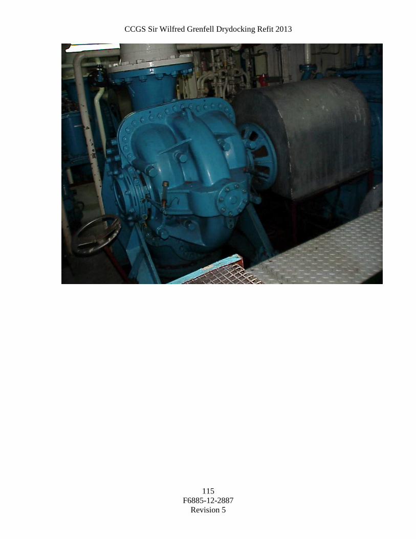
CCGS Sir Wilfred Grenfell Drydocking Refit 2013
F6885-12-2887
Revision 5
115
CCGS Sir Wilfred Grenfell Drydocking Refit 2013
F6885-12-2887
Revision 5
116
Part 4: Proof of Performance 4.1 Inspection 4.1.1 All work and materials used shall be to satisfaction of Chief Engineer.
4.2 Testing 4.2.1 N/A 4.3 Certification 4.3.1 N/A Part 5: Deliverables: 5.1 Drawings/Reports 5.1.1 The contractor shall provide three typewritten service reports to the Chief Engineer. 5.2 Spares 5.2.1 N/A 5.3 Training 5.3.1 N/A 5.4 Manuals 5.4.1 N/A
CCGS Sir Wilfred Grenfell Drydocking Refit 2013
F6885-12-2887
Revision 5
117
Spec item #: E-01 SPECIFICATION TCMSB Field #: 3G014
E-01 Starboard Inboard Main Engine Clutch Survey Part 1: Scope:
1.1 The intent of this item shall be open up the clutch for its 5 year survey by Transport Canada Marine Safety Branch.
1.2 Bosch Rexroth allowance as per ED-08. Part 2: References: 2.1 Guidance Drawings/Nameplate Data 2.1.1 Clutch data: Lohmann+Stolterfoht Type: Pneumaflex KA Model: KAA 280 Mass: 1180 KG All fasteners and piping are metric. 2.2 Standards 2.2.1 Ships ISM Hot-Work, Confined Space, Fall Protection Lockout Procedures 2.3 Regulations N/A 2.4 Owner Furnished Equipment 2.4.1 The contractor shall supply all materials, Parts, equipment, labor and Tools required to perform the specified work. Part 3: Technical Description: 3.1 General 3.1.1. The Contractor shall supply all equipment, staging, chain falls, cranage, slings
and shackles necessary to perform the work. All lifting equipment shall be appropriate for the expected duties, and be accompanied by current certification indicating, or be permanently marked as to being, of an adequate safe working load for the expected duties. Any brackets or other welded attachments required in the performance of this specification shall be welded into place by CWB-certified welders certified to welding Std. W47.1, Div. 1 and 2). Proof of certification must be provided to the Chief Engineer prior to commencement of steel work. Prior to any hot work taking place the Contractor shall ensure the area of work is gas freed suitable for hot work and the appropriate gas free certificates issued and placed as per the requirements of CCG Fleet Safety Manual.
3.1.2. The Contractor shall isolate and lockout both main engines associated with this
clutch, lockout are to be entered into the ships lockout record book and lockouts shall be removed and entered into lockout book after completion of repairs.
Pre Removal
CCGS Sir Wilfred Grenfell Drydocking Refit 2013
F6885-12-2887
Revision 5
118
3.1.3. The contractor shall remove the clutch guard surrounding the clutch as well as any necessary piping, wiring, etc to facilitate the removal of the clutch assembly.
3.1.4. The contractor shall measure and record the clutch drum travel in the ahead and
astern positions as per the manufacturers’ specifications. 3.1.5. The contractor shall measure and record the torsional deformation "angle of twist"
on the spiroflex elements as per the manufacturer's instructions. 3.1.6. Copies of the above readings shall be given to the Chief Engineer prior to
continuing removal of the clutch. 3.1.7. Ship's personnel can assist in taking the readings and special tools for the
measurements can be supplied by the ship. 3.1.8. The contractor shall ensure that all faces of the associated flanges and spacer
plates are properly "proof" marked for subsequent re-assembly and correct orientation.
Removal and Disassembly 3.1.9. Remove the clutch to the contractor's facilities for disassembly. 3.1.10. The contractor shall be aware of the central feed line and seal ring before
removal. 3.1.11. During disassembly of the clutch pack, the contractor shall ensure that all
elements of the pack are proof marked for correct orientation during re-assembly. 3.1.12. Disassemble the clutch to clean and lay out the parts for inspection by the
attending TCMSB Surveyor and Chief Engineer as follows. Separate the tapered jackets, separate the friction cones and spiroflex element, disassemble the clutch cylinder and piston, and remove and discard the piston seals and the sealing cord.
Cleaning and Inspection 3.1.13. Thoroughly clean both tapered jackets and inspect them closely for heat cracks
and discolouration. Lightly buff both sets of friction pads to remove any dirt, grease, oil, etc. and inspect them closely for wear and defects. Clean and inspect all fasteners for wear and defects.
3.1.14. Clean and inspect the four spiroflex elements for wear and defects. Clean and
inspect the cylinder and piston, especially in way of the seal surfaces, for wear and defects.
3.1.15. The attending Transport Canada Marine Safety Surveyor and Chief Engineer shall
inspect the clutch components before re-assembly. 3.1.16. The contractor shall be responsible for arranging the attendance of the TCMS
Surveyor. Re-assembly

CCGS Sir Wilfred Grenfell Drydocking Refit 2013
F6885-12-2887
Revision 5
119
3.1.17. Reassemble the piston and cylinder in good order using new seals and cord with the seals cemented in place with adhesive (ship supply) in accordance with the manufacturer's instructions. Reassemble the friction cones and spiroflex elements in good order. Reassemble the tapered jackets.
3.1.18. All fasteners are be torqued as per the manufacturers specifications. All proof
marks shall be checked. Reassemble any additional removals Pre-Installation Testing 3.1.19. Before the clutch assembly is returned to the vessel the contractor shall pressurize
it to 100 psi to demonstrate that all components are tight and that all seals are operating correctly. This test shall be carried out in the presence of the Chief Engineer.
3.1.20. The duration of the test will be for one hour to the satisfaction of the Chief Engineer.
Re-Installation and Testing 3.1.21. The contractor shall transport the clutch assembly back to the ship and re-install it
in good order ensuring correct orientation of associated flanges and spacer rings using the proof marks. All proof mark locations shall be verified. All fasteners shall be properly torqued.
3.1.22. The contractor shall advise the Chief Engineer when the clutch is ready to be tested .
3.1.23. The ship’s crew will manually operate the clutch to check for correct operation and air leaks after installation with the contractor’s personnel in attendance.
3.1.24. The contractor shall record the clutch travel readings and present them to the
Chief Engineer at this time. 3.1.25. The contractor shall replace all guards, disturbed piping, wiring, and other
removals in good order on completion of the above work. 3.2 Interferences 3.3 Location Part 4: Proof of Performance 4.1 Inspection

CCGS Sir Wilfred Grenfell Drydocking Refit 2013
F6885-12-2887
Revision 5
120
4.1.1 All work and materials used shall be to satisfaction of Chief Engineer.
4.2 Testing 4.2.1 Upon completion of all work, the clutch shall be tested for correct operation with the engine running to the satisfaction of the Chief Engineer. This will include a load or sea trial at the Chief Engineer’s discretion. 4.3 Certification 4.3.1 N/A Part 5: Deliverables: 5.1 Drawings/Reports 5.1.1 Following completion of the above work to the satisfaction of the attending TCMS Surveyor, Chief Engineer a receipt of three typewritten copies of all the measurements and readings are required. 5.2 Spares 5.2.1 N/A 5.3 Training 5.3.1 N/A 5.4 Manuals 5.4.1 N/A

CCGS Sir Wilfred Grenfell Drydocking Refit 2013
F6885-12-2887
Revision 5
121
Spec item #: E-02 SPECIFICATION TCMSB Field #:
3G016
E-02 Starboard Shaft Generator Clutch Survey Scope: 1.1 The intent of this item shall be open up the clutch for its 5 year survey by Transport
Canada Marine Safety Branch. 1.2 Bosch Rexroth allowance as per ED-08. Part 2: References: 2.1 Guidance Drawings/Nameplate Data 2.1.1 Clutch data: Lohmann+Stolterfoht Type: Pneumaflex KA Model: KAZ 160 Mass: 1180 KG All fasteners and piping are metric. 2.2 Standards 2.2.1 Ships ISM Hot-Work, Confined Space, Fall Protection Lockout Procedures 2.3 Regulations N/A 2.4 Owner Furnished Equipment 2.4.1 The contractor shall supply all materials, Parts, equipment, labor and Tools required to perform the specified work. Part 3: Technical Description: 3.1 General 3.1.1. The Contractor shall supply all equipment, staging, chain falls, cranage, slings
and shackles necessary to perform the work. All lifting equipment shall be appropriate for the expected duties, and be accompanied by current certification indicating, or be permanently marked as to being, of an adequate safe working load for the expected duties. Any brackets or other welded attachments required in the performance of this specification shall be welded into place by CWB-certified welders certified to welding Std. W47.1, Div. 1 and 2). Proof of certification must be provided to both the PWGSC Inspection Authority and the Chief Engineer prior to commencement of steel work. Prior to any hot work taking place the Contractor shall ensure the area of work is gas freed suitable for hot work and the appropriate gas free certificates issued and placed as per the requirements of CCG Fleet Safety Manual.
3.1.2. The Contractor shall isolate and lockout both main engines associated with this
clutch, lockout are to be entered into the ships lockout record book and lockouts shall be removed and entered into lockout book after completion of repairs.

CCGS Sir Wilfred Grenfell Drydocking Refit 2013
F6885-12-2887
Revision 5
122
Pre Removal 3.1.3. The contractor shall remove the clutch guard surrounding the clutch as well as
any necessary piping, wiring, etc to facilitate the removal of the clutch assembly. 3.1.4. The contractor shall measure and record the clutch drum travel in the ahead and
astern positions as per the manufacturers’ specifications. 3.1.5. The contractor shall measure and record the torsional deformation "angle of twist"
on the spiroflex elements as per the manufacturer's instructions. 3.1.6. Copies of the above readings shall be given to the Chief Engineer prior to
continuing removal of the clutch. 3.1.7. Ship's personnel can assist in taking the readings and special tools for the
measurements can be supplied by the ship. 3.1.8. The contractor shall ensure that all faces of the associated flanges and spacer
plates are properly "proof" marked for subsequent re-assembly and correct orientation.
Removal and Disassembly 3.1.9. Remove the clutch to the contractor's facilities for disassembly. 3.1.10. The contractor shall be aware of the central feed line and seal ring before
removal. 3.1.11. During disassembly of the clutch pack, the contractor shall ensure that all
elements of the pack are proof marked for correct orientation during re-assembly. 3.1.12. Disassemble the clutch to clean and lay out the parts for inspection by the
attending TCMS Surveyor and Chief Engineer as follows. Separate the tapered jackets, separate the friction cones and spiroflex element, disassemble the clutch cylinder and piston, and remove and discard the piston seals and the sealing cord.
Cleaning and Inspection 3.1.13. Thoroughly clean both tapered jackets and inspect them closely for heat cracks
and discolouration. Lightly buff both sets of friction pads to remove any dirt, grease, oil, etc. and inspect them closely for wear and defects. Clean and inspect all fasteners for wear and defects.
3.1.14. Clean and inspect the four spiroflex elements for wear and defects. Clean and inspect the cylinder and piston, especially in way of the seal surfaces, for wear and defects.

CCGS Sir Wilfred Grenfell Drydocking Refit 2013
F6885-12-2887
Revision 5
123
3.1.15. The attending Transport Canada Marine Safety Surveyor and Chief Engineer shall inspect the clutch components before re-assembly.
3.1.16. The contractor shall be responsible for arranging the attendance of the TCMS
Surveyor. Re-assembly 3.1.17. Reassemble the piston and cylinder in good order using new seals and cord with
the seals cemented in place with adhesive (ship supply) in accordance with the manufacturer's instructions. Reassemble the friction cones and spiroflex elements in good order. Reassemble the tapered jackets.
3.1.18. All fasteners are be torqued as per the manufacturers specifications. All proof
marks shall be checked. Reassemble any additional removals Pre-Installation Testing 3.1.19. Before the clutch assembly is returned to the vessel the contractor shall pressurize
it to 100 psi to demonstrate that all components are tight and that all seals are operating correctly. This test shall be carried out in the presence of the Chief Engineer.
3.1.20. The duration of the test will be for one hour to the satisfaction of the Chief
Engineer. Re-Installation and Testing
3.1.21. The contractor shall transport the clutch assembly back to the ship and re-install it
in good order ensuring correct orientation of associated flanges and spacer rings using the proof marks. All proof mark locations shall be verified. All fasteners shall be properly torqued.
3.1.22. The contractor shall advise the Chief Engineer when the clutch is ready to be
tested 3.1.23. The ship’s crew will manually operate the clutch to check for correct operation
and air leaks after installation with the contractor’s personnel in attendance. 3.1.24. The contractor shall record the clutch travel readings and present them to the
Chief Engineer at this time. 3.1.25. The contractor shall replace all guards, disturbed piping, wiring, and other
removals in good order on completion of the above work. 3.2 Interferences 3.3 Location

CCGS Sir Wilfred Grenfell Drydocking Refit 2013
F6885-12-2887
Revision 5
124
Part 4: Proof of Performance 4.1 Inspection 4.1.1 All work and materials used shall be to satisfaction of Chief Engineer.
4.2 Testing 4.2.1 Upon completion of all work, the clutch shall be tested for correct operation with the engine running to the satisfaction of the Chief Engineer. This will include a load or sea trial at the Chief Engineer’s discretion. 4.3 Certification 4.3.1 N/A Part 5: Deliverables: 5.1 Drawings/Reports 5.1.1 Following completion of the above work to the satisfaction of the attending TCMS Surveyor, Chief Engineer a receipt of three typewritten copies of all the measurements and readings are required. 5.2 Spares 5.2.1 N/A 5.3 Training 5.3.1 N/A 5.4 Manuals 5.4.1 N/A

CCGS Sir Wilfred Grenfell Drydocking Refit 2013
F6885-12-2887
Revision 5
125
Spec item #: E-03 SPECIFICATION TCMSB Field #: N/A
E-03 Safety Valve Calibration and Certification Part 1: Scope: 1.1 The intent of this specification shall be to send all safety valves from the vessels compressed air system to a nationally accredited facility for calibration and certification to satisfy the requirements of TCMS. 1.1.1 This work shall be carried out in Conjunction with the following
N/A
Part 2: References: 2.1 Guidance Drawings/Nameplate Data
Safety Valve Data:
• Main Air Receivers – Set at 34 bar – 4 each • Service Air Receiver – Set at 8.5 bar – 1 each • Clutch Air Receivers – Set at 11.5 bar – 2 each • Emergency Air Receiver – Set at 34 bar – 1 each • Main Air Compressors HP – Set at 33 bar – 2 each • Main Air Compressors LP – Set at 5.5 bar – 2 each • Emergency Air Compressor HP – Set at 33 bar – 1 each • Emergency Air Compressor LP – Set at 5.5 bar – 1 each • Clutch Air Reducing Station – Set at 11 bar – 1 each • Service Air Reducing Station – Set at 7.5 bar – 1 each • De-Icing Reducing Station – Set at 3.5 bar – 1 each • Emergency Air Receiver Reducing Station – Set at 11 bar – 1 each • Oil Mist Detector Reducing Station – Set at 8 bar – 1 each 2.2 Standards 2.2.1 National Institute of Standards Technology 2.3 Regulations 2.3.1 CSA Marine Machinery Regulations 2.4 Owner Furnished Equipment 2.4.1 The contractor shall supply all materials, equipment, labor and parts required to perform the specified work unless otherwise stated. Part 3: Technical Description:
CCGS Sir Wilfred Grenfell Drydocking Refit 2013
F6885-12-2887
Revision 5
126
3.1 General 3.1.1 The Contractor shall ensure that the compressed air system is completely drained and that all compressors are isolated and locked out and recorded in the vessels’ lockout book. 3.1.2 The Contractor shall label each valve for correct location and identification. Valves shall be removed and sent to a nationally accredited facility for calibration and certification. 3.1.3 Valves shall be disassembled, thoroughly cleaned, reassembled and tested. Pressures shall be set as noted in the nameplate section of this item. 3.1.4 The valves shall have replaced new sealant and gaskets where applicable. 3.2 Location 3.2.1 Engine Room Flat Aft Port Side 3.2.2 Engine Room Flat Centerline Aft and Forward 3.2.3 Engine Room Tank Top Forward 3.3 Interferences 3.3.1 The Contractor shall be responsible for the identification of all interference items, their temporary removal, storage and refitting to vessel. Part 4: Proof of Performance 4.1 Inspection 4.1.1 All work shall be completed to the satisfaction of the Chief Engineer and TCMS. 4.2 Testing 4.2.1 All valves shall be tested for leaks after installation when the compressed air system is put back in service. 4.3 Certification 4.3.1 Each valve shall have a calibration certificate. Original copy of each certificate shall be shown to TCMS and then given to the Chief Engineer. Part 5: Deliverables: 5.1 Drawings/Reports 5.1.1 Original copy of each certificate for each valve shall be given to the Chief Engineer. 5.2 Spares 5.2.1 N/A

CCGS Sir Wilfred Grenfell Drydocking Refit 2013
F6885-12-2887
Revision 5
127
Spec item #: L-01 SPECIFICATION TCMSB Field #:
L-01 Kongsberg Tank Level Transducers Part 1: Scope: 1.1 The intent of this item shall be install 7 new owner supply transducers and calibrate
the newly installed and other previously fitted level transducers.
1.2 The contractor shall make an allowance of $5000.00 to arrange the field service representation of Kongsberg to connect, commission and calibrate the installation of the seven owner supplied transducers and for calibration of the thirty four tanks on the tank gauging system.
1.3 Work will be done in conjunction with HD-12 Water Ballast Tank Inspection and
Cleaning and, H-04 Fuel Oil. Lube Oil and Waste Tank Cleaning and Inspection 1.4 Work will entail removing existing welded supports, installing new owner supplied
supports, running cable through existing conduits and bulkheads and connecting new transducers so FSR can calibrate system again.
Part 2: References: 2.1 Nameplate Data 2.1.1 K-Chief System 2.2 Standards 2.2.1 TP-127E Electrical Rules/Regulations, and Canadian Electrical Code 2.2.2 TCMS survey requirements for electrical machinery. 2.2.3 Ships ISM Lockout 2.3 Regulations 2.3.1 Approved by TCMS 2.4 Owner Furnished Equipment 2.4.1 The contractor shall supply all materials, equipment, and parts required to perform the specified work unless otherwise stated Part 3: Technical Description: 3.1 General 3.1.1.

CCGS Sir Wilfred Grenfell Drydocking Refit 2013
F6885-12-2887
Revision 5
128
The Contractor shall be responsible for installation of all sensor brackets and sensors must be installed according to the official Kongsberg documentation. Complete installation of connection wires to the DPU must be in place before Kongsberg Service Engineer is called to vessel. Kongsberg will connect to DPU, commission and calibrate the sensor for each tank. Vessel must be in water and pumps available to fill tanks at time of commissioning. 3.2 Location 3.2.1 : #1 Water Ballast Tanks Port and Stbd (2) # 20 Water Ballast Stability (Anti-roll) Tank (1) #9 Fuel Oil Tanks Port and Stbd (2) #14 Fuel Oil Tanks Port and Stbd (2) 3.3 Interferences 3.3.1 Contractor is responsible for the identification of interference items, their temporary removal, storage and refitting to vessel. Part 4: Proof of Performance 4.1 Inspection 4.1.1 All work shall be completed to the satisfaction of the Chief Engineer. 4.2 Testing 4.2.1 N/A 4.3 Certification 4.3.1 N/A Part 5: Deliverables: 5.1 Drawings/Reports 5.1.1 All reports from the work specified shall be Given to the Chief Engineer. 5.2 Spares 5.2.1 N/A 5.3 Training 5.3.1 N/A 5.4 Manuals 5.4.1 N/A
CCGS Sir Wilfred Grenfell Drydocking Refit 2013
F6885-12-2887
Revision 5
129
Spec item #: L-02 SPECIFICATION TCMS Field #:
L-02 Clutch Control Upgrades Part 1: Scope: 1.1 The intent of this item shall be to install a new owner supplied clutch control system
in the Machinery Control Room and to integrate the new system with the existing Woodward 828 electronic governors.
1.2 The Contractor shall arrange the services of a Woodward Governor Field Services
Representative to install, program, test and commission the clutch control upgrades. 1.3 The Contractor shall make an allowance of $45000.00 for these services. The final
amount shall be adjusted up or down by 1379 action .The final costs will be based on the subcontractor’s invoicing.
1.4 The Contractor shall provide twenty hours labour to assist the Woodward Governor
Field Services Representative. Part 2: References: 2.1 Guidance Drawings/Nameplate Data 2.1.1 N/A 2.2 Standards 2.2.1 N/A 2.3 Regulations 2.3.1 N/A 2.4 Owner Furnished Equipment 2.4.1 The contractor shall supply all materials, equipment, and parts required to perform the specified work unless otherwise stated Part 3: Technical Description: 3.1 General The Contractor shall arrange a Woodward Governor Field Service Representative to provide; Project management, equipment removal, equipment mounting and installation, commissioning, testing and training necessary to complete Phase 2 of the Woodward 828 clutch upgrade. 3.2 Location

CCGS Sir Wilfred Grenfell Drydocking Refit 2013
F6885-12-2887
Revision 5
130
3.2.1. Machinery Control Room Console 3.3 Interferences 3.3.1 Contractor is responsible for the identification of interference items, their temporary removal, storage and refitting to vessel. Part 4: Proof of Performance 4.1 Inspection All work shall be completed to the satisfaction of the Chief Engineer. 4.2 Testing 4.2.1 Dock trials and sea trials to be carried out to verify the operation of the upgraded clutch controls system. 4.3 Certification 4.3.1 N/A Part 5: Deliverables: 5.1 Drawings/Reports 5.1.1 All reports from the work specified shall be Given to the Chief Engineer. 5.2 Spares 5.2.1 N/A 5.3 Training 5.3.1 4 hours training will be provided to the ship engine room personnel by the Woodward Governor FSR. 5.4 Manuals 5.4.1 Clutch controls manuals for upgraded system to be provided to the Chief Engineer.

CCGS Sir Wilfred Grenfell Drydocking Refit 2013
F6885-12-2887
Revision 5
131
Item #: L-03 SPECIFICATION TCMSB Field #: N/A
L-03 Gyro Replacement Part 1: Scope: 1.1 The intent of this work is to install four plates for remounting the gyros. (See attached
pictures for dimensions and locations). 1.2 Contract work should be performed at beginning of refit to allow Technicians time to
install and commission new equipment to be installed. Part 2: References: 2.1 Guidance Drawings/Name plate Data 2.1.1 N/A 2.2 Standards 2.2.1 N/A 2.3 Regulations 2.3.1 N/A 2.4 Owner Furnished Equipment 2.4.1 The contractor shall supply all materials, equipment, and parts required to perform the specified work unless otherwise stated Part 3: Technical Description: 3.1 General
3.1.1. Contractor to remove existing plates as indicated in attached picture. 3.1.2. (2 plates with nothing mounted and 1 plate on deck with 2 Gyros mounted which
will be removed by CCG personnel) 3.1.3. New plates will be ¼ inch aluminium or 3/16 inch steel if aluminium not practical
for welding. 3.1.4. Plates must be bolted or welded in a manner to withstand the stress of a ship
environment and the weight of equipment to be mounted. (40 to 50 lbs of equipment to be mounted per plate)
CCGS Sir Wilfred Grenfell Drydocking Refit 2013
F6885-12-2887
Revision 5
132
3.3 Location Contract work is for the Gyro room.
3.3 Interferences 3.3.1 Contractor is responsible for the identification of interference items, their temporary removal, storage and refitting to vessel. Part 4: Proof of Performance 4.1. All work shall be completed to the satisfaction of the Informatics and Electronics/ Electronic Project Officer (709-772-7738 or 709-682-1524) and the Chief Engineer. 4.2 Testing 4.2.1 N/A 4.3 Certification 4.3.1 N/A Part 5: Deliverables: 5.1 Drawings/Reports 5.1.1 All reports from the work specified shall be Given to the Chief Engineer. 5.2 Spares 5.2.1 N/A 5.3 Training 5.3.1 N/A 5.4 Manuals 5.4.1 N/A 4.1 Inspection