
CCD - ZBAUS. · PDF fileThis scanner is in conformity with CE ... CE‐marked power supply...
74
Advanced Miniature CCD Scan Module 1
Transcript of CCD - ZBAUS. · PDF fileThis scanner is in conformity with CE ... CE‐marked power supply...

Advanced Miniature CCD Scan Module 1


Advanced Miniature CCD Scan Module i
Revision History
Changes to the original manual are listed below:
Version Date Description of Version
1.0 September. 03, 2010 Initial release

Advanced Miniature CCD Scan Module ii
Important Notice
No warranty of any kind is made in regard to this material, including, but not limited to, implied warranties of merchantability or fitness for a particular purpose. We are not liable for any errors contained herein or incidental or consequential damages in connection with furnishing, performance or use of this material. No part of this document may be reproduced, transmitted, stored in a retrieval system, transcribed, or translated into any language or computer language in any form or by any means electronic, mechanical, magnetic, optical, chemical, manual or otherwise, without express written consent and authorization. We reserve the right to make changes in product design without reservation and without notification. The material in this guide is for information only and is subject to change without notice. All trademarks mentioned herein, registered or otherwise, are the properties of their various respective owners. Copyright © 2010. All rights reserved. For CE‐countries This scanner is in conformity with CE standards. Please note that an approved, CE‐marked power supply unit should be used in order to maintain CE conformance. Guidance for Printing 1. This manual is in A5 size. Please double check your printer setting before printing it
out. 2. When printing barcodes for programming, the use of a high‐resolution laser printer
is strongly suggested for the best scan result.

Advanced Miniature CCD Scan Module iii
Table of Contents Important Notice.....................................................................................ii Introduction.............................................................................................1 Overview ...............................................................................................2
Components......................................................................................2 Mounting...............................................................................................3
Scanner Operation...................................................................................4 Precautions ...........................................................................................4 Maintaining the Scanner .......................................................................4 Scan Angles ...........................................................................................5 Scan Zone ..............................................................................................6 Blink Mode ............................................................................................6 Test Button Function .............................................................................7
Trigger Mode.....................................................................................7 Performance Test Mode....................................................................7 Test Mode Settings............................................................................8
Connection ........................................................................................... 10 Free interface ............................................................................ 10 RS‐232 interface ........................................................................ 10 USB interface connection .......................................................... 10
Technical Specification ......................................................................... 11 Dimension ............................................................................................ 13 Programming Guide ............................................................................. 14 Programming Procedure .................................................................... 15 Default Parameters ............................................................................ 16
Scanner Operation......................................................................... 16 Interface Communication .............................................................. 16 Symbologies....................................................................................17 Data Formating .............................................................................. 18 Trigger Command Format.............................................................. 19
Parameter Setting ...............................................................................20 Scanner Operation..........................................................................20
System Function Setting .............................................................20 Interface Setting ........................................................................ 21 Operation Function Setting ....................................................... 22 Same Code Delay....................................................................... 28

Advanced Miniature CCD Scan Module iv
Interface Configuration.................................................................. 29 RS‐232C Interface Setting .......................................................... 29 Same Code Delay....................................................................... 29 Parity Bit .................................................................................... 30 Stop Bit ...................................................................................... 30 Data Bit ...................................................................................... 30 Wand Emulation Setting............................................................ 34
The Symbologies ............................................................................ 36 Codabar Parameter Setting ....................................................... 36 Code 39 Parameter Setting........................................................ 38 Code 93 Parameter Setting........................................................ 40 Code 128 Parameter Setting...................................................... 41 Chinese Post Code Parameter Setting ....................................... 42 MSI/Plessy Parameter Setting ................................................... 43 Code 11 Interface Setting .......................................................... 44 ITF 2 of 5 Parameter Setting ...................................................... 45 Standard 2 of 5 Parameter Setting .............................................47 Industrial 2 of 5 Parameter Setting............................................ 48 UPC/EAN/JAN Parameter Setting .............................................. 49 Telepen Parameter Setting ........................................................ 54 Matrix 2 of 5 Parameter Setting .................................................55 GS1 DataBar Parameter Setting................................................. 56 GS1 DataBar Omnidirectional (Formally RSS‐14) ...................... 56 GS1 DataBar Limited (Formally RSS Limited)..............................57 GS1 DataBar............................................................................... 58
Data Editing.................................................................................... 59 Identifier Code........................................................................... 59 Header and Trailer ..................................................................... 61
Appendix 1: USB Virtual COM Driver Installation...........................62 Appendix 2: Barcode Length Setting.............................................. 63 Appendix 3: Full ASCII Code 39 Table ............................................ 64

Advanced Miniature CCD Scan Module 1
USER’S MANUAL
Introduction
This miniature CCD scan module is especially designed for embedded scanning solution. It only weights 15 grams and sized as small as a match box. There are 3 LED indicators on top allowing immediate scanning response and a test button for performance test. There are mounting holes on the back of the case reserved for quick and easy installation.
The module has a newly designed CCD scan engine with light beam bright and clear as laser beam that gives user best visual indication and its powerful high resolution CCD acts in outstanding performance.
The scanner includes key features as,
World’s smallest CCD scan module in its class
Industrial standard design
A “Test” button on top for performance testing
Mounting holes at bottom for easy installation
Great CCD scanning performance
Future upgradeability on firmware
Best for embedded applications, kiosks, lottery machine, and others where space is limited.

Advanced Miniature CCD Scan Module 2
USER’S MANUAL
Overview
Components
Description Function
OK Indicates a successful reading
NG Indicates a failed reading
Power Indicates the power status
Test Button Used for performance test or trigger scan
Interface Cable Used to connect to the host
Front Window CCD aperture
NG
Power
Test Button
Interface Cable
Front Window
OK

Advanced Miniature CCD Scan Module 3
USER’S MANUAL
Mounting
The scanner is designed to embed into any space limited devices, and it has 3 screwed mounting holes reserved at the bottom.
Figure 1: Screw Position
Back Mounting Holes

USER’S MANUAL
Advanced Miniature CCD Scan Module 4
Scanner Operation
Precautions To ensure the scanner reaches its best performance, the following points need to be noticed when mounting the scanner:
a. Do not place the scanner under direct sunlight or any other bright light source illuminating.
b. When placing the barcode label, one must be careful not to over tilt, skew and/or pitch the barcode (Refer to figure 2)
c. Do not place the device at specula reflection position. The LED light of the scanner reflects directly back on the scanner if it is placed at specula reflection position. As to the nature of CCD sensor, it will not be able to read any barcodes.
d. The barcode label must be placed within the effective depth of field (D.O.F.) since it is the effective reading distance for the barcode from the scanner. For the best placing position, please refer to the Decode Depth of Field drawing. (Figure 3)
Maintaining the Scanner The scanner is designed for long‐term trouble‐free operation and rarely requires any maintenance. Only an occasional cleaning of the scanner window is necessary in order to remove dirt and fingerprints.
Wipe the scan window with a soft lint‐free cloth and a non‐abrasive cleaner to avoid scratching and damaging the scan window. The scan window may be cleaned while the scanner is running.

Advanced Miniature CCD Scan Module 5
USER’S MANUAL
Scan Angles See the following illustrations for the effective barcode reading angles.
Pitch Angle: ±65° normal Specular Reflection: ±5°
Skew Angle: ±65° normal
Roll Angle: ±20° normal (Prevents reading of a barcode if all the bars are not inside the reading beam or if tilt is more than 20°.)
Figure 2: Skew, Pitch and Roll Angle Illustration
Test condition: using a 100% EAN 13 barcode, 0.33mm (13 mil), at a distance of 14cm (5.5”) in optimal lighting conditions.
USER’S MANUAL
Advanced Miniature CCD Scan Module 6
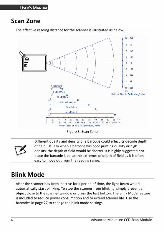
Scan Zone The effective reading distance for the scanner is illustrated as below.
Figure 3: Scan Zone
Different quality and density of a barcode could effect its decode depth of field. Usually when a barcode has poor printing quality or high density, the depth of field would be shorter. It is highly suggested not place the barcode label at the extremes of depth of field as it is often easy to move out from the reading range.
Blink Mode After the scanner has been inactive for a period of time, the light beam would automatically start blinking. To stop the scanner from blinking, simply present an object close to the scanner window or press the test button. The Blink Mode feature is included to reduce power consumption and to extend scanner life. Use the barcodes in page 27 to change the blink mode settings

Advanced Miniature CCD Scan Module 7
USER’S MANUAL
Test Button Function On top of the scan module, there is a “Test” button, and it controls two function modes:
Trigger mode
Scan performance test mode
Trigger Mode
When the module is in trigger mode, the reading light beam remains off and scanning is only made when the “Test” button is depressed.
In trigger mode, simply aim the scan module at the barcode and press the “Test” button to trigger scan light beam and decode.
Performance Test Mode
To enter into scan performance test mode, press the “Test” button twice quickly. The LED indicators will be turned off and you will hear three short beep sounds. This indicates that the module has successfully entered the test mode. Place the barcode label within its scan range to get the best scan performance result.
The result is indicated with LED lights with different read rate as below:
Read Rate % 50% 75% 90%
OK_LED On On On
NG_LED Off On On
PWR_LED Off Off On
Press the “Test” button once to exit the scan performance test mode and return to its original setting.
The LED will stay on for 1 second every time you turn on the module. You may only use the light beam to scan the “Start Of Configuration” barcode in this second. This feature is designed for users to change settings without pressing the “Test” button when the module is in trigger mode.

USER’S MANUAL
Advanced Miniature CCD Scan Module 8
Test Mode Settings
The “Test” button and the performance test settings can be configured using the following set‐up barcodes:
*Default values are highlighted in gray background.
Start Of Configuration
“Test” Button Function Setting Barcode Value
Barcode Label Description
Complex mode ‐The test button controls both trigger mode and scan performance test mode.
ST01
When the scanner is set in this mode, press the “Test” button once to scan and press the “Test” button twice quickly to activate the scan performance test function.
Scan performance test mode only ‐Pressing the “Test” button will activate scan performance test mode only.
ST02
When the scanner is set in this mode, press and hold the “Test” button for 2 seconds to perform a scan test.
ST03
Trigger mode only ‐The test button only functions as a trigger.
End Of Configuration

USER’S MANUAL
Advanced Miniature CCD Scan Module 9
Start Of Configuration
Performance Test Mode Beeper Selection Barcode Value
Barcode Label Description
LB13
Beeper disable ‐Beeper disabled in performance test.
LB14
Beeper enable ‐Beeper enabled in performance test.
Performance Test Mode Data Transmission Barcode Value
Barcode Label Description
LB15
Data transmission disable in performance test ‐Data not transmitted in performance test.
LB16
Data transmission enable in performance test ‐Data is transmitted in performance test.
End Of Configuration

Advanced Miniature CCD Scan Module 10
USER’S MANUAL
Connection
The scan module has 3 different kinds of interface connection to suit customer’s desire; the standard cable is black, straight and 2 m (6.5 feet) in length. Below shows the connector types and pin out configuration for each interface.
Free interface RS‐45 10P10C for multi‐interface connection
Pin # Function
1 RTS_EIA
2 USB_D+
3 USB_D‐
4 GND
5 CTS_EIA
6 RX_EIA
7 Trigger In
8 +5V Input
9 N.C.
10 TX_EIA
RS‐232 interface Power adapter required if host can not provide sufficient power.
Pin # Function
1 N.C.
2 TX_EIA
3 RX_EIA
4 N.C.
5 GND
6 N.C.
7 CTS_EIA
8 RTS_EIA
9 +5V Input
Inner of DC‐Jack: +5V DC Outer of DC‐Jack: GND
USB interface connection
Pin # Function
1 VBUS
2 D‐
3 D+
4 VSS

USER’S MANUAL
Advanced Miniature CCD Scan Module 11
Technical Specification
Power Requirement Input voltage LED on LED off Decode
5V ±10% VDC 105mA typical 55mA typical 120mA typical Max. 250mA @ 1msec peak
Operational Sensor Illumination Depth of field Scan rate Minimum bar width Print contrast Indicators (LED) Beeper operation Scan angle Pitch angle Skew angle Specular reflection angle System interface
Linear CCD array 617nm visible red LED 280mm (UPC/EAN 100%, PCS=90%) 330 scans per second 0.1mm (0.07mm actually) (Code 39, PCS=90%) 30% @ UPC/EAN 100% “OK”, “NG”, “PWR” and “TEST” Programmable tone & beep time 43° ±65° ±65° ±5° RS‐232C, HID USB, and USB‐Virtual COM port emulation
Environment Operating temperature Storage temperature Humidity Ambient light immunity Shock Vibration
0℃ ~ 50℃ (32℉ ~ 122℉ )
‐20℃ ~ 60℃ (‐4℉ ~ 140℉)
5% to 95% non‐condensing 100,000 Lux max. (Sunlight) 2,000G 5~2KHz. 6.0G rms. 3‐axis.

USER’S MANUAL
Advanced Miniature CCD Scan Module 12
~Technical Specification Continued~
Physical dimension Height Width Depth Weight Mounting
15.8mm (0.62”) 26.6mm (1.05”) 39.0mm (1.54”) 15g 3‐M1.6 * 0.35 screw hole
Regulatory Regulator approval
According CE, FCC, VCCI, BSMI,RoHS compliant
Decode symbology UPC/JAN/EAN, UPC A & E, EAN‐8, EAN‐13, ISBN/ISSN, Code 39, Codabar, Code 128, EAN 128, Code 93, Interleave 2 of 5, Addendum 2 or 5, IATA Code, MSI/Plessy, Chinese Postal Code, Code 32 (Italian Pharmacode), Industrial 2 of 5, Standard 2 of 5, Matrix 2 of 5 (JAP), Code 11, GS1 DataBar, Telepen

USER’S MANUAL
Advanced Miniature CCD Scan Module 13
Dimension

USER’S MANUAL
Advanced Miniature CCD Scan Module 14
Programming Guide
Scanning a series of programming bar code labels can configure the scanner. This allows decoding options and interface protocols to be tailored to a specific application. The configuration is stored in non‐volatile memory and will not be lost by removing power from the scanner.
The scanner must be properly powered before programming. For RS‐232C type scanners, an external power adapter might be necessary to supply DC power to the scanner.
During the programming mode, the scanner will acknowledge a good and valid reading with a short beep. It will give long beeps for either an invalid or bad reading.
See the Default Parameter section for all the programmable parameters. The default settings will be restored whenever the “Reset” programming label is scanned.

Advanced Miniature CCD Scan Module 15
USER’S MANUAL
Programming Procedure Below is the programming procedure for using barcodes in this guide.
1. Power up the scanner.
2. Scan the Start of Configuration barcode.
3. Scan the barcode for the desired feature. Multiple features can be enabled/disabled before scanning the End of Configuration barcode.
4. Scan the End of Configuration barcode and save the new configuration.
5. To give up a configuration change, power off the scanner before scanning the End of Configuration barcode or scan the Abort barcode.
6. For some parameter setting, such as barcode length and identifier code, it is required to scan the Set barcode to save the configuration.
Default values are highlighted in gray background.
Scan the “Start of Configuration” barcode
Scan the “End of Configuration” barcode
Scan the “Abort” barcode Power off the scanner
Finish the configuration
Scan barcode of the desired feature
Power up the scanner
Discard the configuration

Advanced Miniature CCD Scan Module 16
USER’S MANUAL
Default Parameters This table gives the default settings of all the programmable parameters. The default settings would be restored whenever the laser scanner reads the “Reset” programming label in programming mode. If you wish to change any setting, scan the appropriate barcodes below.
Scanner Operation
Parameter Default
Same code delay 500ms
Scan mode Auto scan
Beeping frequency Medium
Beeping duration 50ms
LED/Beep before data transmission On
Header and trailer None
Inter message delay None
Inter character delay None
Interface Communication
Parameter Default
RS‐232 Interface
Baud rate 9600
Parity none
Data Bits 8
Stop Bit 1
RTS/CTS off
Terminator <CR><LF>
USB Interface
Terminator type Enter
Code mode Scan code
Keyboard US keyboard
Wand Emulation
Wand emulation speed Normal
Data output Black=high

USER’S MANUAL
Advanced Miniature CCD Scan Module 17
Symbologies
Parameter Default
Decoder Selection
EAN/UPC Enable
Code 39 Enable
Code 32 Disable
Codabar Enable
ITF 2 of 5 Enable
MSI Disable
Chinese Post Code Disable
Code 93 Enable
Code 128 Enable
EAN‐128 Disable
Telepen Disable
Code 11 Disable
Standard 2 of 5 Disable
Industrial 2 of 5 Disable
Matrix 2 of 5 Disable
GS1 DataBar Disable
Code Identifiers
Identifier code as factory standard Disable
Identifier code as AIM standard Disable
Code 39 identifier code M
ITF 2 of 5 identifier code I
Chinese post code identifier code H
UPC‐A identifier code A
UPC‐E identifier code E
EAN‐13 identifier code F
EAN‐8 identifier code FF
Codabar identifier code N
Code 128 identifier code K
Code 93 identifier code L
MSI identifier code P
Code 11 identifier code O
S Standard 2 of 5 identifier code
D Industrial 2 of 5 identifier code
G Matrix 2 of 5 identifier code
RS GS1 DataBar identifier code

Advanced Miniature CCD Scan Module 18
USER’S MANUAL
GS1 DataBar Limited identifier code RL GS1 DataBar Expanded identifier code RX
Barcode Length
maximum 32 Codabar Code 11 Standard 2 of 5 Industrial 2 of 5 Matrix 2 of 5
minimum 6
maximum 62 Code 39 Code 93 Code 128 minimum 3
maximum 16 Chinese Post Code
minimum 10
maximum 32 MSI ITF 2 of 5 minimum 4
maximum 14 GS1 DataBar GS1 DataBar Limited minimum 14
maximum 48 GS1 DataBar Expanded
minimum 6
Data Formating
Code Message Format
EAN‐13 D1 D2 D3 D4 D5 D6 D7 D8 D9 D10 D11 D12 D13
EAN‐8 D1 D2 D3 D4 D5 D6 D7 D8
UPC‐A D1 D2 D3 D4 D5 D6 D7 D8 D9 D10 D11 D12
UPC‐E D1 D2 D3 D4 D5 D6 D7 D8
Code 128 D1‐Dx (default 3~62)
EAN‐128 C1 D1‐Dx (default 3~62)
Code 39 D1‐Dx (default 3~62)
Codabar D1‐Dx (default 6~32)
ITF 2 of 5 D1‐Dx (default 6~32)
Chinese Post Code D1‐Dx (default 8~32)
Code 93 D1‐Dx (default 3~32)
MSI D1‐Dx (default 6~32)

USER’S MANUAL
Advanced Miniature CCD Scan Module 19
Trigger Command Format
(Only for RS‐232C and USB‐Virtual COM Port)
Level Trigger Command
Command Description
<ESC>A0<CR> When the scanner receives this command, the CCD/laser would light up and start scanning barcodes entering its scan filed.
The light would be switched off when the scanner receives a trigger off command.
Edge Trigger Command
Command Description
<ESC>A0.mm<CR> When the scanner receives this command, the CCD/laser would light up and start scanning barcode entering its scan field.
The light would remain on until the scanner reads a barcode or until “mm” period is over.
The scanner is not controlled by the trigger off command.
<ESC>A2<CR> When the scanner receives this command, the CCD/laser light would light up and remain on but the device can only scan once.
The light would be switched off when the scanner receives a trigger off command.
<ESC>A2.mm<CR> When the scanner receives this command, the CCD/laser light would light up and remain on until “mm” period is over.
If the scanner read a barcode before “mm” period is over, the light‐off countdown would re‐start.
The scanner is not controlled by the trigger off command.
Trigger Off Command
Command Description
The CCD/laser light would be switched off when the scanner receives a trigger off command.
<ESC>A1<CR>

Advanced Miniature CCD Scan Module 20
USER’S MANUAL
Parameter Setting
Start Of Configuration
Scanner Operation
System Function Setting Barcode Value
Barcode Label Description
‐‐
Reset (return to factory default)
%/
Display firmware version
++
Abort :exit programming mode with no update
KE94 Return to customer default
KE95 Save as customer default
End Of Configuration

Advanced Miniature CCD Scan Module 21
USER’S MANUAL
Start Of Configuration
Interface Setting Barcode Value
Barcode Label Description
KE97 Return to USB default
KE99 Return to RS‐232 default
KE87 Enable USB virtual COM (Virtual COM driver required. For installation steps refer to Appendix 1.)
KE01 Enable IBM PC/AT/PS/2 Keyboard emulation
KE05 Enable stand‐alone keyboard (Required no keyboard or key simulator. Only available for special firmware version.)
KE98 Enable wand emulation (Only available for special firmware version.)
KE77 Enable OPOS/JPOS (Available for USB interface only and requires driver. For RS‐232 interface, the scanner needs reset and identifier code has to be enabled.)
End Of Configuration

Advanced Miniature CCD Scan Module 22
USER’S MANUAL
Start Of Configuration
Operation Function Setting Good Read Beeper Tone Selection
Barcode Value
Barcode Label Description
GR02 Low beeper tone
GR01 Medium beeper tone
GR03 High beeper tone
GR05 Speaker disable
Beeper Sound Selection Barcode Value
Barcode Label Description
GR13 Very short (5 ms)
GR12 Short (20 ms)
GR11 Medium (50 ms)
GR10 Long (100 ms)
GR14 Very Long (200 ms)
GR15 Ultra long (500 ms)
End Of Configuration

Advanced Miniature CCD Scan Module 23
USER’S MANUAL
Start Of Configuration
Beeper Volume Selection
Barcode Value
Barcode Label Description
GR20 Loud
GR21 Medium
GR22 Slight
Beeper Timing Selection Barcode Value
Barcode Label Description
LB00 LED/Beep after transmission Use this barcode to indicate a “good read”
after a barcode has been successfully decoded.
LB01 LED/Beep before transmission Use this barcode to indicate a “good read”
before successfully transmitting the barcode data to the host.
LB03 Power‐on tone enable
LB04 Power‐on tone disable
End Of Configuration

USER’S MANUAL
Advanced Miniature CCD Scan Module 24
Start Of Configuration
Scan Function Setting
Barcode Value
Barcode Label Description
SM01
Trigger mode The scanner becomes inactive once the data is
transmitted. It must be triggered to active again.
Auto scan mode SM02
The scanner will actively scan and decode barcodes, and the same barcode cannot be read twice.
Repeat mode SM05
It is similar to auto scan mode, but double reading on the same barcode is permitted if uses trigger.
“Test” Button Function Setting Barcode Value
Barcode Label Description
Complex mode ST01
The test button controls both trigger mode and scan performance test mode.
ST02
Scan performance test mode only The test button only functions as scan
performance test mode. Press down “Test” button continuously over 2
seconds and it starts to perform scan test. ST03
Trigger mode only The test button only functions as a trigger.
End Of Configuration

USER’S MANUAL
Advanced Miniature CCD Scan Module 25
Start Of Configuration
Performance Test Mode Beeper Selection
Barcode Value
Barcode Label Description
LB13
Beeper disable Beeper disabled in performance test.
LB14
Beeper enable Beeper enabled in performance test.
Performance Test Mode Data Transmission Barcode Value
Barcode Label Description
LB15
Data transmission disable in performance test Data not transmitted in performance test.
LB16
Data transmission enable in performance test Data is transmitted in performance test.
End Of Configuration
USER’S MANUAL
Advanced Miniature CCD Scan Module 26
Start Of Configuration
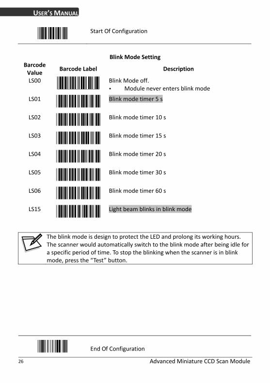
Blink Mode Setting
Barcode Value
Barcode Label Description
Blink Mode off. LS00
Module never enters blink mode
Blink mode timer 5 s LS01
LS02
Blink mode timer 10 s
LS03
Blink mode timer 15 s
LS04
Blink mode timer 20 s
LS05
Blink mode timer 30 s
LS06
Blink mode timer 60 s
LS15
Light beam blinks in blink mode
The blink mode is design to protect the LED and prolong its working hours. The scanner would automatically switch to the blink mode after being idle for a specific period of time. To stop the blinking when the scanner is in blink mode, press the “Test” button.
End Of Configuration

USER’S MANUAL
Advanced Miniature CCD Scan Module 27
Start Of Configuration
Inter Message Delay
Barcode Value
Barcode Label Description
IM01 0 ms
IM02 100 ms
IM03 500 ms
IM04 1000 ms
Inter Character Delay Barcode Value
Barcode Label Description
IC01 0 ms
IC05 2 ms
5 ms IC00
IC02 10 ms
IC03 20 ms
IC04 50 ms
End Of Configuration

USER’S MANUAL
Advanced Miniature CCD Scan Module 28
Start Of Configuration
Same Code Delay
Barcode Value
Barcode Label Description
SD01 Same code delay time 50 ms
Same code delay time 100 ms SD02
Same code delay time 200 ms SD03
SD04 Same code delay time 300 ms
SD05 Same code delay time 400 ms
Same code delay time 500 ms SD06
Same code delay time 600 ms SD07
SD08 Same code delay time 700 ms
SD09 Same code delay time 800 ms
Same code delay time 900 ms SD10
Same code delay time 1000 ms SD11
SD12 Same code delay time Infinite
End Of Configuration

USER’S MANUAL
Advanced Miniature CCD Scan Module 29
Start Of Configuration
Interface Configuration
RS‐232C Interface Setting
Same Code Delay
Barcode Value
Barcode Label Description
BR09 115200
BR08 57600
BR00 38400
19200 BR01
BR02 9600
4800 BR03
BR04 2400
BR05 1200
End Of Configuration

USER’S MANUAL
Advanced Miniature CCD Scan Module 30
Start Of Configuration
Parity Bit
Barcode Value
Barcode Label Description
PB01 Even parity
Odd parity PB02
PB03 Mark parity
PB04 Space parity
PB05 None parity
Stop Bit
Barcode Value
Barcode Label Description
SB01 1 stop bit
SB02 2 stop bit
Data Bit
Barcode Value
Barcode Label Description
DB07 7 data bit
8 data bit DB08
End Of Configuration

USER’S MANUAL
Advanced Miniature CCD Scan Module 31
Start Of Configuration
Handshaking Protocol
Barcode Value
Barcode Label Description
HP01 None handshaking
ACK/NAK HP02
Xon/Xoff HP03
RTS/CTS HP04
LB07 Enable beeper on <BEL> character
Ignore beep on <BEL> character LB08
Disable ACK/NAK timeout beeper LB09
RT01 ACK/NAK response time 300 ms
ACK/NAK response time 500 ms RT03
ACK/NAK response time 1 s RT05
RT02 ACK/NAK response time 2 s
ACK/NAK response time 3 s RT04
ACK/NAK response time 5 s RT06
RT07 ACK/NAK response time infinity
End Of Configuration

USER’S MANUAL
Advanced Miniature CCD Scan Module 32
Start Of Configuration
Message Terminator
Barcode Value
Barcode Label Description
DT11 RS‐232 message terminator—none
DT12 RS‐232 message terminator—CR/LF
DT13 RS‐232 message terminator—CR
DT14 RS‐232 message terminator—LF
DT15 RS‐232 message terminator—H‐tab
DT16 RS‐232 message terminator—STX/ETX
DT17 RS‐232 message terminator—EOT
End Of Configuration

USER’S MANUAL
Advanced Miniature CCD Scan Module 33
Start Of Configuration
Keyboard Setting
Barcode Value
Barcode Label Description
Capital lock on CP00
CP01 Capital lock off
Function key emulation enable CP05
CP06 Function key emulation disable
CP18 Send number as normal data
CP19 Send number as keypad data
Alphabet follow as keyboard CP20
CP21 Alphabet always upper case
CP22 Alphabet always Lower case
Message Terminator
Barcode Value
Barcode Label Description
DT01 Keyboard terminator‐‐‐none
Keyboard terminator‐‐‐Enter DT02
Keyboard terminator‐‐‐H‐TAB DT03
End Of Configuration

USER’S MANUAL
Advanced Miniature CCD Scan Module 34
Start Of Configuration
Wand Emulation Setting Wand emulation is a standard interface but requires special firmware. If needed, please contact your distributor. Barcode Value
Barcode Label Description
All barcode will be decoded and transmitted in that symbology
WD01
Enable Wand output data format as Code 39 WD02
Wand emulation data output black = high WO01 Scan this barcode to set quiet zones and
spaces low and bars =high.
Wand emulation data output black=low WO02 Scan this barcode to set quiet zones and
spaces high and bars=low
Idle = high WO03 Idle state refers to the TTL logic level of the
Wand Emulation signal when not in use
Idle = low WO04 Idle state refers to the TTL logic level of the
Wand Emulation signal when not in use
WS01 Wand emulation speed‐‐‐Low This option allows the transmission of wand
emulation at 1ms narrow element width
Wand emulation speed‐‐‐medium WS02 This option allows the transmission of wand
emulation at 600us narrow element width
End Of Configuration

USER’S MANUAL
Advanced Miniature CCD Scan Module 35
Start Of Configuration
Wand Emulation Speed
Barcode Value
Barcode Label Description
Wand emulation speed‐‐‐normal WS03
WS04 Wand emulation speed‐‐‐high This option allows the transmission of wand
emulation at 300us narrow element width
Wand emulation speed‐‐‐higher WS05 This option allows the transmission of wand
emulation at 100 us narrow element width
Wand emulation narrow/wide ratio 1:2 WS00
Wand emulation narrow/wide ratio 1:3 WS08
End Of Configuration

USER’S MANUAL
Advanced Miniature CCD Scan Module 36
Start Of Configuration
The Symbologies
Codabar Parameter Setting Barcode Value
Barcode Label Description
Codabar enable RC02
Codabar disable RD02
Codabar start/stop character transmission-none CB05
Codabar start/stop character transmission-A,B,C,D CB06
Codabar start/stop character transmission-
DC1~DC4
CB07
Codabar start/stop character transmission-
a/t,b/n,c/*,d/e
CB08
Codabar maximum length setting CB09
Codabar minimum length setting CB10
Confirm to save this setting (required for reading full ASCII table and length setting)
SET
CB11 Codabar concatenation disable
CB12 Codabar concatenation enable
End Of Configuration

USER’S MANUAL
Advanced Miniature CCD Scan Module 37
Start Of Configuration
Codabar (Continued) Barcode Value
Barcode Label Description
CB13 No check character
Validate modulo 16,but don’t transmit CB14
Validate modulo 16 and transmit CB15
Codabar data redundant check=off DC50
Codabar data redundant check=1 DC51
Codabar data redundant check=2 DC52
Codabar data redundant check=3 DC53
End Of Configuration

USER’S MANUAL
Advanced Miniature CCD Scan Module 38
Start Of Configuration
Code 39 Parameter Setting Barcode Value
Barcode Label Description
Code 39 enable RC01
Code 39 disable RD01
Code 32 enable RC13
Code 32 disable RD13
DC00 Code 39 data redundant check=off
Code 39 data redundant check=1 DC01
Code 39 data redundant check=2 DC02
Code 39 data redundant check=3 DC03
Standard code 39 3901
Full ASCII code 39 3902
Code 39 start/stop character transmission 3903
Code 39 start/stop character without transmission 3904
End Of Configuration

USER’S MANUAL
Advanced Miniature CCD Scan Module 39
Start Of Configuration
Code 39 (Continued) Barcode Value
Barcode Label Description
3905 Code 39 check digit calculate and transmit
3906 Code 39 check digit calculate but without transmit
3907 No check character
3908 Code 39 maximum length setting
3909 Code 39 minimum length setting
Confirm to save this setting (required for reading full ASCII table and length setting)
SET
3910 Code 39 concatenation enable
3911 Code 39 concatenation disable
3912 Code 32 (Italian pharmacy) transmit “A” character
3913 Code 32 (Italian pharmacy) without transmit ”A” character
End Of Configuration

USER’S MANUAL
Advanced Miniature CCD Scan Module 40
Start Of Configuration
Code 93 Parameter Setting Barcode Value
Barcode Label Description
Code 93 enable RC08
Code 93 disable RD08
Code 93 data redundant check=off DC30
Code 93 data redundant check=1 DC31
Code 93 data redundant check=2 DC32
Code 93 data redundant check=3 DC33
Code 93 maximum length setting 9301
Code 93 minimum length setting 9302
Confirm to save this setting (required for reading full ASCII table and length setting)
SET
9303 Code 93 check digit calculate but without transmit
Code 93 check digit not calculate and without transmit
9304
Code 93 check digit calculate and transmit 9305
End Of Configuration

USER’S MANUAL
Advanced Miniature CCD Scan Module 41
Start Of Configuration
Code 128 Parameter Setting Barcode Value
Barcode Label Description
Code 128 enable RC06
RD06 Code 128 disable
RC10 EAN‐128 enable
RD10 EAN‐128 disable
DC40 Code 128 data redundant check=off
DC41 Code 128 data redundant check=1
DC42 Code 128 data redundant check=2
DC43 Code 128 data redundant check=3
Code128 FNC2 concatenation enable 1801
1802 Code128 FNC2 concatenation disable
1803 No check character
1804 Calculate but not transmitted
1805 Calculate and transmit
1806 Code 128 maximum length setting
1807 Code 128 minimum length setting
Confirm to save this setting (required for reading full ASCII table and length setting)
SET
End Of Configuration

USER’S MANUAL
Advanced Miniature CCD Scan Module 42
Start Of Configuration
Chinese Post Code Parameter Setting Barcode Value
Barcode Label Description
Chinese post code enable RC05
Chinese post code disable RD05
Chinese post code data redundant check=off DC60
Chinese post code data redundant check=1 DC61
Chinese post code data redundant check=2 DC62
Chinese post code data redundant check=3 DC63
Chinese post code maximum length setting SZ01
Chinese post code minimum length setting SZ02
Confirm to save this setting (required for reading full ASCII table and length setting)
SET
End Of Configuration

USER’S MANUAL
Advanced Miniature CCD Scan Module 43
Start Of Configuration
MSI/Plessy Parameter Setting Barcode Value
Barcode Label Description
MSI enable RC14
RD14 MSI disable
DC70 MSI data redundant check= off
DC71 MSI data redundant check=1
DC72 MSI data redundant check=2
DC73 MSI data redundant check=3
MS01 MSI/Plessy maximum length setting
MSI/Plessy minimum length setting MS02
Confirm to save this setting (required for reading full ASCII table and length setting)
SET
MS03 MSI/Plessy double check digit calculate but not transmit
MS04 MSI/Plessy double check digit without calculate and transmit
MSI/Plessy double check digit calculate but only first digit transmit
MS05
MS06 MSI/Plessy double check digit calculate and both transmit
MS07 MSI/Plessy single check digit calculate but without transmit
MS08 MSI/Plessy single check digit calculate and transmit
End Of Configuration

USER’S MANUAL
Advanced Miniature CCD Scan Module 44
Start Of Configuration
Code 11 Interface Setting Barcode Value
Barcode Label Description
Code 11 enable RC07
Code 11 disable RD07
Code 11 maximum length setting 1101
Code 11 minimum length setting 1102
Confirm to save this setting (required for reading full ASCII table and length setting)
SET
1103 Code 11 one check digit verification
Code 11 two check digit verification 1104
Two Check for Code 11 check digit if code length is longer than 10 characters
1105
Disable verification 1106
Code 11 check digit transmitted 1107
Code 11 check digit not transmitted 1108
End Of Configuration

USER’S MANUAL
Advanced Miniature CCD Scan Module 45
Start Of Configuration
ITF 2 of 5 Parameter Setting Barcode Value
Barcode Label Description
ITF 2 of 5 enable RC04
ITF 2 of 5 disable RD04
RC09 IATA code enable
RD09 IATA disable
ITF 25 data redundant check=off DC80
DC81 ITF25 data redundant check=1
DC82 ITF25 data redundant check=2
DC83 ITF25 data redundant check=3
ITF 2 of 5 no check character IT03
IT04 ITF 2 of 5 check digit calculate and transmit
IT05 ITF 2 of 5 check digit calculate but without transmit
End Of Configuration

USER’S MANUAL
Advanced Miniature CCD Scan Module 46
Start Of Configuration
ITF 2 of 5 (Continued) Barcode Value
Barcode Label Description
IT01 ITF 2 of 5 code maximum length setting
IT02 ITF 2 of 5 code minimum length setting
ITF 2 of 5 one fixed length setting IT06
ITF 2 of 5 two fixed length setting IT07
Confirm to save this setting (required for reading full ASCII table and length setting)
SET
End Of Configuration

USER’S MANUAL
Advanced Miniature CCD Scan Module 47
Start Of Configuration
Standard 2 of 5 Parameter Setting Barcode Value
Barcode Label Description
Standard 2 of 5 code enable RC22
RD22 Standard 2 of 5 code disable
D051 Standard 2 of 5 code maximum length setting
D052 Standard 2 of 5 code minimum length setting
Confirm to save this setting (required for reading full ASCII table and length setting)
SET
D053 Standard 2 of 5 code no check character
Standard 2 of 5 code check digit calculate and transmit
D054
Standard 2 of 5 code check digit calculate but without transmit
D055
End Of Configuration

USER’S MANUAL
Advanced Miniature CCD Scan Module 48
Start Of Configuration
Industrial 2 of 5 Parameter Setting Barcode Value
Barcode Label Description
Industrial 2 of 5 code enable RC21
RD21 Industrial 2 of 5 code disable
D251 Industrial 2 of 5 code maximum length setting
D252 Industrial 2 of 5 code minimum length setting
Confirm to save this setting (required for reading full ASCII table and length setting)
SET
D253 Industrial 2 of 5 code no check character
D254 Industrial 2 of 5 code check digit calculate and transmit
Industrial 2 of 5 code check digit calculate but without transmission
D255
End Of Configuration

USER’S MANUAL
Advanced Miniature CCD Scan Module 49
Start Of Configuration
UPC/EAN/JAN Parameter Setting Barcode Value
Barcode Label Description
RC11 EAN convert to ISSN/ISBN enable
RD11 EAN convert to ISSN/ISBN disable
RC03 UPC/EAN/JAN enable
UPC/EAN/JAN disable RD03
UE01 UPC/EAN/JAN all enable
UE02 EAN‐8 or EAN‐13 enable
UE03 UPC‐A and EAN‐13 enable
UPC‐A and UPC‐E enable UE04
UE05 UPC‐A enable
UE06 UPC‐E enable
UE07 EAN‐13 enable
UE08 EAN‐8 enable
UE09 UPC/EAN Addendum disable
End Of Configuration

USER’S MANUAL
Advanced Miniature CCD Scan Module 50
Start Of Configuration
UPC/EAN/JAN (Continued) Barcode Value
Barcode Label Description
UE10 Add on 5 only
UE11 Add on 2 only
UE12 Add on 2 or 5
UE13 Force UPC‐E to UPC‐A format enable
UE14 Force UPC‐E to UPC‐A format disable
UE15 Force UPC‐A to EAN‐13 format enable
UE16 Force UPC‐A to EAN‐13 format disable
UE44 Force EAN‐8 to EAN‐13 format enable
UE45 Force EAN‐8 to EAN‐13 format disable
UE17 Transmit UPC‐A check digit enable
UE18 Transmit UPC‐A check digit disable
UE19 Transmit UPC‐E leading character enable
UE20 Transmit UPC‐E leading character disable
UE21 Transmit UPC‐E check digit enable
UE22 Transmit UPC‐E check digit disable
End Of Configuration

USER’S MANUAL
Advanced Miniature CCD Scan Module 51
Start Of Configuration
UPC/EAN/JAN (Continued) Barcode Value
Barcode Label Description
UE23 Transmit EAN‐8 check digit enable
UE24 Transmit EAN‐8 check digit disable
UE25 Transmit EAN‐13 check digit enable
UE26 Transmit EAN‐13 check digit disable
UE27 Transmit UPC‐A leading character enable
UE28 Transmit UPC‐A leading character disable
UE30 Add‐on format with separator
UE31 Add‐on format without separator
UE60 EAN‐13 country code first “0” can transmitted
UE61 EAN‐13 country code first:”0” can’t transmitted
UE66 EAN‐13 with first 0 ID code same as “UPC‐A”
UE67 EAN‐13 with first 0 ID code same as “EAN‐13”
DC10 UPC‐A data redundant check=off
DC11 UPC‐A data redundant check=1
End Of Configuration

USER’S MANUAL
Advanced Miniature CCD Scan Module 52
Start Of Configuration
UPC/EAN/JAN (Continued) Barcode Value
Barcode Label Description
DC12 UPC‐A data redundant check=2
DC13 UPC‐A data redundant check=3
DC14 UPC‐E data redundant check=off
DC15 UPC‐E data redundant check=1
DC16 UPC‐E data redundant check=2
DC17 UPC‐E data redundant check=3
DC20 EAN‐13 data redundant check=off
DC21 EAN‐13 data redundant check=1
DC22 EAN‐13 data redundant check=2
DC23 EAN‐13 data redundant check=3
DC24 EAN‐8 data redundant check=off
DC25 EAN‐8 data redundant check=1
DC26 EAN‐8 data redundant check=2
DC27 EAN‐8 data redundant check=3
UE32 EAN/UPC +add‐on (none mandatory)
UE33 EAN/UPC +add‐on (mandatory)
End Of Configuration

USER’S MANUAL
Advanced Miniature CCD Scan Module 53
Start Of Configuration
UPC/EAN/JAN (Continued) UE35 EAN/UPC +add‐on mandatory for 978/977 bookland
(Supplement requirement, not sent for other)
UE38 EAN/UPC +addon mandatory for 978/977 bookland (Supplement requirement, optionally for other)
UE42 EAN/UPC +addon mandatory for 491 Japanese bookland (Supplement requirement, not sent for other)
UE43 EAN/UPC +addon mandatory 491 Japanese bookland (Supplement requirement, optionally for other)
End Of Configuration

USER’S MANUAL
Advanced Miniature CCD Scan Module 54
Start Of Configuration
Telepen Parameter Setting Barcode Value
Barcode Label Description
RC25 Telepen enable
RD25 Telepen disable
TE03 Telepen numeric mode enable
TE04 AIM Telepen enable
End Of Configuration

USER’S MANUAL
Advanced Miniature CCD Scan Module 55
Start Of Configuration
Matrix 2 of 5 Parameter Setting Barcode Value
Barcode Label Description
RC12 Matrix 2 of 5 enable
RD12 Matrix 2 of 5 disable
D151 Matrix 2 of 5 maximum length setting
D152 Matrix 2 of 5 minimum length setting
SET
Confirm to save this setting (required for reading full ASCII table and length setting)
D153 Matrix 2 of 5 no check character
D154 Matrix 2 of 5 check digit calculate and transmit
D155 Matrix 2 of 5 check digit calculate but without transmission
End Of Configuration

USER’S MANUAL
Advanced Miniature CCD Scan Module 56
Start Of Configuration
GS1 DataBar Parameter Setting There are 7 kinds of barcodes in the GS1 DataBar family and they are categorized into three groups. Barcode types in the same group use the same barcodes for setting.
Group Representative Contents
Group 1 GS1 DataBar Omnidirectional GS1 DataBar Omnidirectional GS1 DataBar Truncated (Formally RSS‐14) GS1 DataBar Stacked GS1 DataBar Stacked Omnidirectional
Group 2 GS1 DataBar Limited (Formally RSS Limited)
GS1 DataBar Limited
Group 3 GS1 DataBar Expanded (Formally RSS Expanded)
GS1 DataBar Expanded GS1 DataBar Expanded Stacked
GS1 DataBar Omnidirectional (Formally RSS‐14) Barcode Value
Barcode Label Description
RC15 GS1 DataBar Omnidirectional enable
RD15 GS1 DataBar Omnidirectional disable
SS00 Transmit GS1 DataBar Omnidirectional check digit
SS01 Do not transmit GS1 DataBar Omnidirectional check digit
SS02 Transmit GS1 DataBar Omnidirectional application ID (01)
SS03 Do not transmit GS1 DataBar Omnidirectional application ID (01)
GS1 DataBar Omnidirectional /EAN‐128 emulation enable
SS05
GS1 DataBar Omnidirectional /EAN‐128 emulation disable
SS04
End Of Configuration

USER’S MANUAL
Advanced Miniature CCD Scan Module 57
Start Of Configuration
GS1 DataBar Limited (Formally RSS Limited) Barcode Value
Barcode Label Description
RC16 GS1 DataBar Limited enable
RD16 GS1 DataBar Limited disable
SS10 Transmit GS1 DataBar Limited check digit
SS11 Don’t transmit GS1 DataBar Limited check digit
SS12 Transmit GS1 DataBar limited application ID (01)
SS13 Do not transmit GS1 DataBar limited application ID
End Of Configuration
USER’S MANUAL
Advanced Miniature CCD Scan Module 58
Start Of Configuration
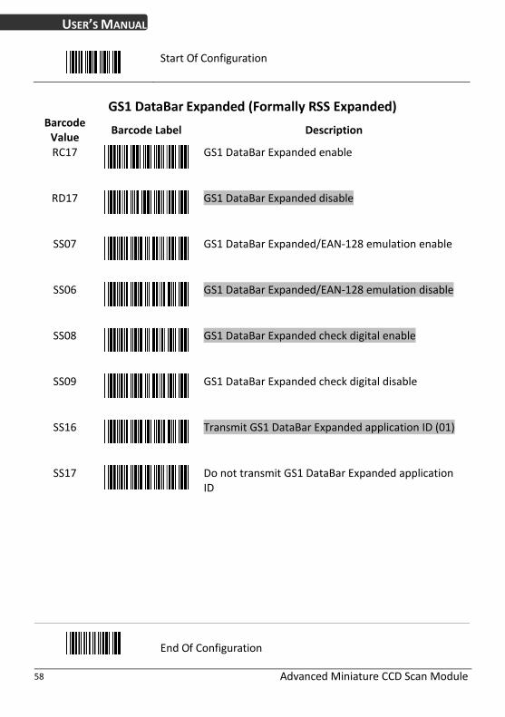
GS1 DataBar Expanded (Formally RSS Expanded) Barcode Value
Barcode Label Description
RC17 GS1 DataBar Expanded enable
RD17 GS1 DataBar Expanded disable
SS07 GS1 DataBar Expanded/EAN‐128 emulation enable
SS06 GS1 DataBar Expanded/EAN‐128 emulation disable
SS08 GS1 DataBar Expanded check digital enable
SS09 GS1 DataBar Expanded check digital disable
SS16 Transmit GS1 DataBar Expanded application ID (01)
SS17 Do not transmit GS1 DataBar Expanded application ID
End Of Configuration

USER’S MANUAL
Advanced Miniature CCD Scan Module 59
Start Of Configuration
Data Editing
Identifier Code Barcode Value
Barcode Label Description
IS00 Disable identifier code
IS01 Enable identifier code table as factory standard
IS03 Enable identifier code table as AIM standard.
CI01 Code 39 identifier code setting
CI02 ITF 2 of 5 identifier code setting
CI03 Chinese Post Code identifier code setting
CI04 UPC‐E identifier code setting
CI05 UPC‐A identifier code setting
CI06 EAN‐13 identifier code setting
CI07 EAN‐8 identifier code setting
SET
Confirm to save this setting (required for reading full ASCII table and length setting)
End Of Configuration

USER’S MANUAL
Advanced Miniature CCD Scan Module 60
Start Of Configuration
Barcode Value
Barcode Label Description
CI08 Codabar identifier code setting
Code 128 identifier code setting CI09
Code 93 identifier code setting CI10
CI11 MSI identifier code setting
CI12 GS1 DataBar Omnidirectional identifier code setting
CI13 GS1 DataBar Limited identifier code setting
GS1 DataBar expanded identifier code setting CI14
CI15 Industrial 2 of 5 identifier code setting
CI16 Code 11 Identifier code setting
Standard 2 of 5 identifier code setting CI17
CI18 Matrix 2 of 5 identifier code setting
SET Confirm to save this setting (required for reading full ASCII table and length setting)
End Of Configuration

USER’S MANUAL
Advanced Miniature CCD Scan Module 61
Start Of Configuration
Header and Trailer Barcode Value
Barcode Label Description
CP11 Add code length as header enable (2 digits)
CP12 Add code length as header disable (2 digits)
HT01 Header (Preamble)
HT02 Trailer (Postamble)
HT03 Truncate header character
HT04 Truncate trailer character
SET
Confirm to save this setting (required for reading full ASCII table and length setting)

USER’S MANUAL
Advanced Miniature CCD Scan Module 62
Appendix 1: USB Virtual COM Driver Installation
Contact your distributor to get the driver and follow the steps below to enable USB virtual COM port.
1. Connect the handheld scanner and the host (e.g. a PC) with a USB interface cable.
2. Enable USB virtual COM port with programming barcodes on page 21.
3. After the programming, the host would request driver installation. Browse your files to locate the driver and start installation.
4. The USB virtual COM port is ready for use after driver installation.
USER’S MANUAL
Advanced Miniature CCD Scan Module 63
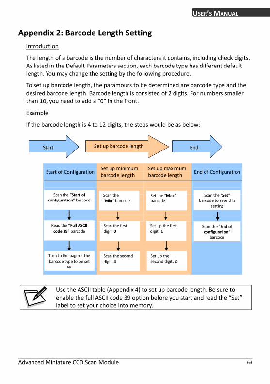
Appendix 2: Barcode Length Setting
Introduction
The length of a barcode is the number of characters it contains, including check digits. As listed in the Default Parameters section, each barcode type has different default length. You may change the setting by the following procedure.
To set up barcode length, the paramours to be determined are barcode type and the desired barcode length. Barcode length is consisted of 2 digits. For numbers smaller than 10, you need to add a “0” in the front.
Example
If the barcode length is 4 to 12 digits, the steps would be as below:
Start up barcode length End Set
Start of ConfigurationSet up minimum Set up maximum
End of Configuration barcode length barcode length
Scan the “Start of configuration” barcode
Scan the “Min“ barcode
Scan the “Set” barcode to save this
settin
Set the “Max” barcode
g
Set up the second digit: 2
Scan the first digit: 0
Read the “Full ASCII code 39” barcode
Set up the first digit: 1
Scan the “End of configuration”
barcode
Tubarcode type to be set
u
rn to the page of the Scan the second digit: 4
p
Use the ASCII table (Appendix 4) to set up barcode length. Be sure to enable the full ASCII code 39 option before you start and read the “Set” label to set your choice into memory.

USER’S MANUAL
Advanced Miniature CCD Scan Module 64
Start Of Configuration
Appendix 3: Full ASCII Code 39 Table
Code 39 ASCII Hexa‐co
de Code 39 ASCII
Hexa‐code
Full ASCII ‐‐‐NUL 00 Full ASCII ‐‐‐SI Function key‐‐‐‐‐“Shift”
0F
Full ASCII ‐‐‐SOH Function key‐‐‐‐‐“Ins”
01 Full ASCII ‐‐‐DLE
Function key‐‐‐‐‐“5(num)”
10
Full ASCII ‐‐‐STX Function key‐‐‐‐‐“Del”
02 Full ASCII ‐‐‐DC1 11 Function key‐‐‐‐‐“F1”
03 12 Full ASCII ‐‐‐ETX Full ASCII ‐‐‐DC2 Function key‐‐‐‐‐“Home” Function key‐‐‐‐‐“F2”
04 13 Full ASCII ‐‐‐EOT Full ASCII ‐‐‐DC3 Function key‐‐‐‐‐“End” Function key‐‐‐‐‐“F3”
05 14 Full ASCII ‐‐‐ENQ Function key‐‐‐‐‐“Up arrow”
Full ASCII ‐‐‐DC4 Function key‐‐‐‐‐“F4”
Full ASCII ‐‐‐ACK Function key‐‐‐‐‐“Down arrow”
06 Full ASCII ‐‐‐NAK Function key‐‐‐‐‐“F5”
15
Full ASCII ‐‐‐BEL Function key‐‐‐‐‐“Left arrow”
07 16 Full ASCII ‐‐‐SYN Function key‐‐‐‐‐“F6”
08
Full ASCII ‐‐‐BS Full ASCII ‐‐‐ETB Function key‐‐‐‐‐“Backspace” Function key‐‐‐‐‐“F7”
17
Full ASCII ‐‐‐HT Function key‐‐‐‐‐“TAB”
09 Full ASCII ‐‐‐CAN Function key‐‐‐‐‐“F8”
18
Full ASCII ‐‐‐LF Function key‐‐‐‐‐“Enter (alpha numeric”
0A Full ASCII ‐‐‐EN Function key‐‐‐‐‐“F9”
19
Full ASCII ‐‐‐VT Function key‐‐‐‐‐“right arrow”
0B 1A Full ASCII ‐‐‐SUB Function key‐‐‐‐‐“F10”
0C
Full ASCII ‐‐‐FF Full ASCII ‐‐‐ESC Function key‐‐‐‐‐“PgUp” Function key‐‐‐‐‐“F11”
1B
Full ASCII ‐‐‐CR Function key‐‐‐‐‐“Enetr(num.)”
0D 1C Full ASCII ‐‐‐FS Function key‐‐‐‐‐“F12”
0E Full ASCII ‐‐‐GS 1D
Full ASCII ‐‐‐SO Function key‐‐‐‐‐“PgDn” Function key‐‐‐‐‐“ESC”
End Of Configuration

USER’S MANUAL
Advanced Miniature CCD Scan Module 65
Start Of Configuration
Full ASCII Code 39 Table
Code 39 ASCII Hexa‐code Code 39 ASCII Hexa‐code
Full ASCII ‐‐‐RS Function key‐‐‐‐‐“CTL(L)”
1E
Full ASCII ‐‐‐‐ 2D
1F 2E Full ASCII ‐‐‐US
Full ASCII ‐‐‐. Function key‐‐‐‐‐“ALT(L)”
20 Full ASCII ‐‐‐SP Full ASCII ‐‐‐/
2F
21
Full ASCII ‐‐‐0 30 Full ASCII ‐‐‐!
Full ASCII ‐‐‐“ 22
Full ASCII ‐‐‐1 31
Full ASCII ‐‐‐# 23
Full ASCII ‐‐‐2 32
24 Full ASCII ‐‐‐$
Full ASCII ‐‐‐3 33
Full ASCII ‐‐‐% 25
Full ASCII ‐‐‐4 34
Full ASCII ‐‐‐& 26
Full ASCII ‐‐‐5 35
Full ASCII ‐‐‐‘ 27
36 Full ASCII ‐‐‐6
28 37 Full ASCII ‐‐‐ (
Full ASCII ‐‐‐7
29 Full ASCII ‐‐‐) Full ASCII ‐‐‐8
38
Full ASCII ‐‐‐* 2A
Full ASCII ‐‐‐9 39
Full ASCII ‐‐‐+ 2B 3A Full ASCII ‐‐‐:
2C Full ASCII ‐‐‐; 3B Full ASCII ‐‐‐,
End Of Configuration

Advanced Miniature CCD Scan Module 66
USER’S MANUAL
Start Of Configuration
Full ASCII Code 39 Table
Code 39 ASCII Hexa‐code Code 39 ASCII Hexa‐code
Full ASCII ‐‐‐< 3C
Full ASCII ‐‐‐K 4B
Full ASCII ‐‐‐= 3D
Full ASCII ‐‐‐L 4C
Full ASCII ‐‐‐> 3E
Full ASCII ‐‐‐M 4D
Full ASCII ‐‐‐? 3F
Full ASCII ‐‐‐N 4E
Full ASCII ‐‐‐@ 40
Full ASCII ‐‐‐O 4F
Full ASCII ‐‐‐A 41
Full ASCII ‐‐‐P 50
Full ASCII ‐‐‐B 42
Full ASCII ‐‐‐Q 51
Full ASCII ‐‐‐C 43
Full ASCII ‐‐‐R 52
Full ASCII ‐‐‐D 44
Full ASCII ‐‐‐S 53
Full ASCII ‐‐‐E 45
Full ASCII ‐‐‐T 54
Full ASCII ‐‐‐F 46
Full ASCII ‐‐‐U 55
Full ASCII ‐‐‐G 47
Full ASCII ‐‐‐V 56
Full ASCII ‐‐‐H 48
Full ASCII ‐‐‐W 57
Full ASCII ‐‐‐I 49
Full ASCII ‐‐‐X 58
Full ASCII ‐‐‐J 4A
Full ASCII ‐‐‐Y 59
End Of Configuration

USER’S MANUAL
Advanced Miniature CCD Scan Module 67
Start Of Configuration
Full ASCII Code 39 Table
Hexa‐codeCode 39 ASCII Code 39 ASCII Hexa‐code
Full ASCII ‐‐‐Z 5A Full ASCII ‐‐‐i 69
Full ASCII ‐‐‐[ 5B Full ASCII ‐‐‐j
6A
5C 6B Full ASCII ‐‐‐\ Full ASCII ‐‐‐k
5D Full ASCII ‐‐‐] Full ASCII ‐‐‐l
6C
Full ASCII ‐‐‐^ 5E Full ASCII ‐‐‐m 6D
Full ASCII ‐‐‐_ 5F Full ASCII ‐‐‐n
6E
60 Full ASCII ‐‐‐o 6F Full ASCII ‐‐‐`
61
Full ASCII ‐‐‐a Full ASCII ‐‐‐p 70
Full ASCII ‐‐‐b 62 Full ASCII ‐‐‐q 71
Full ASCII ‐‐‐c 63 Full ASCII ‐‐‐r
72
64 Full ASCII ‐‐‐s 73 Full ASCII ‐‐‐d
65 74
Full ASCII ‐‐‐e Full ASCII ‐‐‐t
66 75
Full ASCII ‐‐‐f Full ASCII ‐‐‐u
67 Full ASCII ‐‐‐g
Full ASCII ‐‐‐v 76
Full ASCII ‐‐‐h 68 Full ASCII ‐‐‐w 77
End Of Configuration

USER’S MANUAL
Advanced Miniature CCD Scan Module 68
Start Of Configuration
Full ASCII Code 39 Table
Hexa‐code
Code 39 ASCII
Full ASCII ‐‐‐x 78
79 Full ASCII ‐‐‐y
7A Full ASCII ‐‐‐z
7B Full ASCII ‐‐‐{
Full ASCII ‐‐‐| 7C
Full ASCII ‐‐‐} 7D
7E Full ASCII ‐‐‐~
Full ASCII ‐‐‐DEL 7F
End Of Configuration