CCD JBC 082306 - Snap-on · PDF filemoving fan blades. 5. If an extension cord is necessary,...
86
Form 5815-6.. 4.3 ® Operators Manual - Pro32 Conventional Sensor Systems
Transcript of CCD JBC 082306 - Snap-on · PDF filemoving fan blades. 5. If an extension cord is necessary,...

Form 5815-6.. 4.3
®
Op
erat
ors
Man
ual
- P
ro32
Co
nve
nti
on
al S
enso
r S
yste
ms

Blank page

I
Safety
Safety InformationFor your safety, read this manual thoroughly before operating the equipment.
The Aligner is intended for use by properly trained skilled automotive technicians. The safety messagespresented in this section and throughout the manual are reminders to the operator to exercise extremecare when performing wheel alignments with this product.
There are many variations in procedures, techniques, tools, and parts for servicing vehicles, as well asthe skill of the individual doing the work. Because of the vast number of vehicle applications and potentialuses of the product, the manufacturer cannot possibly anticipate or provide advice or safety messagesto cover every situation. It is the automotive technician’s responsibility to be knowledgeable of thevehicle to be aligned. It is essential to use proper service methods and perform wheel alignments in anappropriate and acceptable manner that does not endanger your safety, the safety of others in the workarea or the equipment or vehicle being serviced.
It is assumed that, prior to using the Aligner, the operator has a thorough understanding of the vehiclesystems being serviced. In addition, it is assumed he has a thorough knowledge of the operation andsafety features of the alignment rack or lift, and has the proper hand and power tools necessary toperform wheel alignments.
When using your garage equipment, basic safety precautions should always be followed, including:
1. Read all instructions.2. Care must be taken as burns can occur from touching hot parts.3. Do not operate equipment with a damaged power cord or if the equipment has been dropped or
damaged until it has been examined by a qualified serviceman.4. Do not let cord hang over edge of table, bench or counter or come in contact with hot manifolds or
moving fan blades.5. If an extension cord is necessary, a cord with a current rating equal to or more than that of the
equipment should be used. Cords rated for less than the equipment may overheat. Care should betaken to arrange the cord so that it will not be tripped over or pulled.
6. Always unplug equipment from electrical outlet when not in use. Never use the cord to pull the plugfrom the outlet. Grasp plug and pull to disconnect.
7. Let equipment cool completely before putting away. Loop cord loosely around equipment whenstoring.
8. To reduce the risk of fire, do not operate equipment in the vicinity of open containers of flammableliquids, such as gasoline.
9. Adequate ventilation should be provided when working on operating internal combustion engines.10. Keep hair, loose clothing, fingers, and all parts of body away from moving parts.11. To reduce the risk of electrical shock, do not use on wet surfaces or expose to rain.12. Use only as described in this manual. Use only manufacturer’s recommended attachments.13. ALWAYS WEAR SAFETY GLASSES. Everyday eyeglasses only have impact resistant lenses, they
are NOT safety glasses.
IMPORTANT!! SAVE THESE INSTRUCTIONSDO NOT DISCARD!!

II
Safety
Safety INSTRUCTIONSIMPORTANT!! SAVE THESE INSTRUCTIONS
Risk of electrical shock.••••• Do not operate equipment with a damaged power cord or if the equipment
has been dropped or damaged, until it has been examined by a qualifiedservice person.
••••• If an extension cord is necessary, a cord with a current rating equal to orgreater than that of the equipment should be used. Cords rated for lesscurrent than the equipment can overheat.
••••• Unplug equipment from electrical outlet when not in use. Never use thecord to pull the plug from the outlet. Grasp plug and pull to disconnect.
••••• Do not expose the equipment to rain. Do not use on wet surfaces.••••• Plug unit into correct power supply.••••• Do not remove or bypass grounding pin.Contact with high voltages can cause death or serious injury.
Risk of electrical shock. High voltages are present within the console unit.••••• There are no user serviceable items within the console other than the
keyboard and printer.••••• Service on the unit must be performed by qualified personnel.••••• Do not open any part of the console other than noted areas.••••• Turn power switch off and unplug the unit before servicing.Contact with high voltages can cause death or serious injury.
Risk of eye injury. Debris, dirt, and fluids may drop from vehicles.••••• Knock off any loose debris. Clean surfaces as needed to avoid any
materials from falling.••••• Wear approved safety glasses when servicing.Debris, dirt, and fluids can cause serious eye injury.
Risk of crushing. Vehicles may roll off alignment lift if not secured.••••• Leave automatic transmission in park or manual transmission in gear
unless equipment operation steps require vehicle in neutral.••••• Apply parking brake unless equipment operation steps require wheel
movement.••••• Use wheel chocks whenever vehicle is positioned on the lift.••••• Follow rack or lift manufacturer’s safety recommendations when lifting a
vehicle.Vehicles rolling off lifts can cause death or serious injury.

III
Safety
Risk of entanglement or crushing. There are moving parts on vehicle lifts duringoperation.••••• Keep all persons clear of lifts.••••• Read lift manufacturer’s operation instructions carefully.••••• Follow lift manufacturer’s safety recommendations.Contact with moving parts could cause injury.
Risk of pinching or crushing body parts when jacking vehicles.••••• Keep hands and other body parts away from jacking surfaces.••••• Do not use unapproved adapters (i.e. wooden blocks) when jacking a
vehicle.••••• Do not bypass any jack manufacturer’s safety features.••••• Read jack manufacturer’s operation instructions carefully.••••• Follow jack manufacturer’s safety recommendations.Improperly used or maintained jacks can cause injury.
Risk of burns.••••• Do not touch hot exhaust systems, manifolds, engines, radiators, etc.••••• Wear gloves whenever performing a service near hot components.Hot components can cause burns.
Risk of injury. Tools may break or slip if improperly used or maintained.••••• Use the correct tool for the task.••••• Frequently inspect, clean, and lubricate (if recommended) all tools.••••• Follow recommended procedures when performing vehicle services.Tools that break or slip can cause injury.

Blank Page

Table of Contents
iii
Table of Contents
Safety INSTRUCTIONS .................................................................................................................. II
Introduction _________________________________________________________________ 1-1Getting started ............................................................................................................................... 1-1Assembly and Setup ...................................................................................................................... 1-1
Aligner Location ........................................................................................................................ 1-1Power ON .................................................................................................................................. 1-1
Aligner Components ...................................................................................................................... 1-2Console ..................................................................................................................................... 1-2Sensor connections ................................................................................................................... 1-2Computer Connections ............................................................................................................. 1-2Wheel Clamps ........................................................................................................................... 1-3Measuring Sensors ................................................................................................................... 1-3Aligner Software ........................................................................................................................ 1-4Screen Layout and Navigation .................................................................................................. 1-5Remote Display Unit (Optional) ................................................................................................. 1-6
Toolbar Buttons .............................................................................................................................. 1-7
Setup - Preferences __________________________________________________________ 2-1Preferences Screen ....................................................................................................................... 2-1Preferences Tab Flow Chart .......................................................................................................... 2-2Interaction ...................................................................................................................................... 2-3
Features................................................................................................................................ 2-3Displays ................................................................................................................................ 2-4User Login ............................................................................................................................ 2-4
Logout .............................................................................................................................. 2-5Lost or Forgotten Passwords ........................................................................................... 2-6Usage Log ........................................................................................................................ 2-6
Security ..................................................................................................................................... 2-6Units .......................................................................................................................................... 2-6
Resolution ............................................................................................................................. 2-7Angle Units ........................................................................................................................... 2-7Linear Units ........................................................................................................................... 2-8Loading Units ........................................................................................................................ 2-8Pressure Units ...................................................................................................................... 2-8
Connectivity Options ................................................................................................................. 2-8Romess Inclinometer ................................................................................................................ 2-8Select Wizard ............................................................................................................................ 2-8Store Name ............................................................................................................................... 2-9Regional Settings ...................................................................................................................... 2-9
Languages ............................................................................................................................ 2-9Specifications ...................................................................................................................... 2-10
System .................................................................................................................................... 2-10Turntables ...................................................................................................................... 2-10Sensors .......................................................................................................................... 2-11
Shutting Down the Computer ....................................................................................................... 2-11

Table of Contents
iv
Steps to Performing a 4-Wheel Alignment ________________________________________ 3-1Mounting the Wheel Clamps ......................................................................................................... 3-2
Optional Wheel Clamp Accessories .......................................................................................... 3-3Hub Flange Adapter for “Wheel off” adjustments ..................................................................... 3-3
Home Alignment Tab ...................................................................................................................... 3-4Using the Wizard Procedure .......................................................................................................... 3-5
Wizard versus Manual Operation............................................................................................. 3-5Typical Wizard Procedures ....................................................................................................... 3-5
Sample alignment process. ........................................................................................................... 3-5Run Wizard ........................................................................................................................... 3-5Begin a New Alignment ........................................................................................................ 3-6Select Vehicle Manufacturer, Year and Model ...................................................................... 3-6
Vehicle Manufacturer or Make ......................................................................................... 3-6Vehicle Year ..................................................................................................................... 3-7Vehicle Model ................................................................................................................... 3-7Custom Specifications ...................................................................................................... 3-7
View Specifications ............................................................................................................... 3-8Editing Specifications ....................................................................................................... 3-8Adjustment Animations..................................................................................................... 3-8Additional Assistance ....................................................................................................... 3-9
Enter Customer Data (Advanced Feature) ........................................................................... 3-9Adding Customer Information ........................................................................................ 3-10Selecting a Stored Record ............................................................................................. 3-10Recalling a Previous Alignment...................................................................................... 3-10Adding a New Customer ................................................................................................ 3-10Editing an Existing Record ............................................................................................. 3-11Using the Database Outside the Aligner Platform.......................................................... 3-11
Inspection ........................................................................................................................... 3-11Using Inspection Reports ............................................................................................... 3-12
Perform Runout Compensation .......................................................................................... 3-12Runout Status ................................................................................................................. 3-13More Information on Runout .......................................................................................... 3-14
Prepare for Caster Measurement ....................................................................................... 3-14Lower Wheels and Jounce (settle) the Suspension ....................................................... 3-14Install Brake Pedal Depressor ........................................................................................ 3-15Level and Lock Measurement Sensors .......................................................................... 3-15Center the Steering ........................................................................................................ 3-15
Perform Caster Turn ........................................................................................................... 3-15Automatic or Manual Caster Sweep............................................................................... 3-16Turn to 10 Degrees Left ................................................................................................. 3-16Turn to 10 Degrees Right ............................................................................................... 3-16Turn Wheels Straight Ahead .......................................................................................... 3-16Information about Caster Accuracy ................................................................................ 3-17
Calibration Check ............................................................................................................... 3-17Vehicle Dimensions / Setback ............................................................................................ 3-18All Readings........................................................................................................................ 3-18

Table of Contents
v
Rear Readings .................................................................................................................... 3-18Cross Values / Total Toe ................................................................................................. 3-19Readings Toolbar ........................................................................................................... 3-19
Level and Lock Steering Wheel .......................................................................................... 3-20Front Readings Screen....................................................................................................... 3-20
Loop Button .................................................................................................................... 3-21Zoom .............................................................................................................................. 3-21
Print Results ....................................................................................................................... 3-21Inspections ................................................................................................................................... 3-22MAP ............................................................................................................................................. 3-22Vehicle Dynamics ......................................................................................................................... 3-22
Manual Diagnostics ................................................................................................................. 3-23Automatic Diagnostics ............................................................................................................. 3-23Bent Parts Diagnosis ............................................................................................................... 3-23
Measure ...................................................................................................................................... 3-24Steering Axis Inclination (SAI) and Included Angle (IA) .......................................................... 3-25Measuring Steering Axis Inclination (SAI) and Included Angle ............................................... 3-25Camber at Zero Toe ................................................................................................................ 3-26Vehicle Dimensions / Setback ................................................................................................. 3-27Toe-Out-On-Turns (or Turning Radius) ................................................................................... 3-27Maximum Turn Angle .............................................................................................................. 3-28Toe Curve Change .................................................................................................................. 3-29Ride Height .............................................................................................................................. 3-29
Adjust .......................................................................................................................................... 3-30Live Caster, Camber and Toe.................................................................................................. 3-31Elevated Camber and Toe ....................................................................................................... 3-31Adjust Caster and/or Camber, Toe on Turntables ................................................................... 3-32Adjust Caster, Camber and Toe Elevated ............................................................................... 3-33Adjust Front Camber Elevated ................................................................................................ 3-34Adjust Rear Camber Elevated................................................................................................. 3-34
3-35Adjust A-arms .......................................................................................................................... 3-35EZ Toe ..................................................................................................................................... 3-36Cradle Adjust ........................................................................................................................... 3-37Drag Link Adjust ...................................................................................................................... 3-38Single Tie Rod Adjust .............................................................................................................. 3-38Shims and Kits ........................................................................................................................ 3-39Default Part Vendor ................................................................................................................. 3-39INFO ........................................................................................................................................ 3-39Front Offset Cam Bushings ..................................................................................................... 3-40ADR Adjustment ...................................................................................................................... 3-40

Table of Contents
vi
Maintenance _________________________________________________________ 4-1Maintenance Menu ........................................................................................................................ 4-1Calibration Menu ............................................................................................................................ 4-2Camber/SAI/Cross Toe Calibration ................................................................................................ 4-2Calibration Factors ......................................................................................................................... 4-2Calibration History .......................................................................................................................... 4-2ISO Certification ............................................................................................................................. 4-3Front Sensor Calibration procedures ............................................................................................. 4-4Rear Sensor Calibration ................................................................................................................ 4-7Preventative Maintenance ............................................................................................................. 4-8
Maintenance Checklist .............................................................................................................. 4-8Maintenance History .................................................................................................................. 4-8
Wizards - Editing and Creating ...................................................................................................... 4-9Modifying Existing OEM Wizards .............................................................................................. 4-9
Adding a Procedure .............................................................................................................. 4-9Deleting a Procedure ............................................................................................................ 4-9Adding a Wizard ................................................................................................................. 4-10Loop Back to Previous Step ............................................................................................... 4-10Skip Allowed ....................................................................................................................... 4-10
Speaker Training (Voice Control) ................................................................................................. 4-11Database Utilities ......................................................................................................................... 4-12Windows® Utilities ....................................................................................................................... 4-12

1-1
Introduction
Introduction
The following chapters detail basic, advanced and platinum software features which may ormay not be included in all aligner models. This document primarily is designed to cover softwarenavigation and features with minimum regard to the hardware platform in which it resides. Thereare many variations of aligner models each of which may utilize different features of the basesoftware package.
Getting startedThe aligner software offers extraordinary power and versatility. This section of the manualdescribes how to begin enjoying the many features and benefits. References are often made toother sections of the Operator’s Manual.
Assembly and SetupInstallation and setup of a new aligner is best handled by a qualified Representative. If unsure ofwho to contact, refer to the backpage of this manual.The aligner must be calibrated to at least one rack, lift, or other surface where wheel alignmentsare to be performed.All software is loaded onto the computer’s hard drive. The Software Discs shipped with the unitcontains the alignment software as a backup, and is not needed when performing alignments.All standard alignment features are activated at manufacture. Advanced features are activatedas they are purchased with “Activation Codes”.
Setups for the PC hardware and Microsoft® Windows® are preset at the factory to maximizeperformance and should not be altered.
Aligner LocationLocate the aligner in a location that provides the most convenience for the operator. Visualcontact with the monitor is necessary during most steps of a wheel alignment.
Power ONThe main power switch for the aligner is located on the rear of the cabinet. This switch appliespower to all of the aligner’s components. Most of the individual electronic components containa power switch as well. Make sure the monitor’s power switch and the computer’s power switch(in cabinet drawer) are left in the ON position at all times.
When the power switch is turned on, the unit initiates the computer boot-up. The boot sequencemay take several minutes. If any problems are encountered during the boot-up sequence,consult the Maintenance and Service section of this Operator’s Manual. The computer willautomatically load the alignment software beginning with the logo screen. Click OK to advanceto the Home Alignment screen indicating the aligner is ready for operation.

1-2
Introduction
Aligner Components
ConsoleThe console houses many of the aligner componentsincluding the power supplies, the computer system,the sensor interface components, and provides placesfor the display monitor, keyboard, and printer. Themeasurement sensors are stored on the sides of thecabinet when not in use.
The upper shelf of the console provides a location forthe display monitor and space for a mouse andkeyboard.
The console also houses the computer system and asliding drawer for a printer.
NOTE: Do not expose the aligner or measuringsensors to water, heavy dust environments,or operations that produce metal chips. Donot block the rear of the computer or disablethe cooling fan.
Sensor connectionsThe sensor interconnect cables plug into the back ofthe console. There are 6 female connectors – one foreach of the 4 sensors, one for the optional remotedisplay unit, and one spare. When the aligner isutilized with a rack wiring kit, all 6 connectors are used.The connectors are universal – it does not matter whichsensor is plugged into any of the 6 connectors.
CAUTION! DO NOT CHANGE COMPUTER CONNECTIONSOR COMPONENTS UNLESS INSTRUCTED BYAUTHORIZED PERSONNEL.
CAUTION! CALL FOR A CERTIFIED TECHNICIAN IF YOUARE IN DOUBT AS TO HOW TO MAKE ANY CONNECTION.MAKING A CONNECTION INCORRECTLY COULDDAMAGE THE UNIT AND VOID THE WARRANTY.
Computer ConnectionsInstallation of the aligner includes connection ofdevices to the computer. Care should be taken if therebe any reason to examine those connections, orchange a component such as the pointing device.

1-3
Introduction
Note: Refer to the manuals supplied with thecomputer and the maintenance chapter forcomputer connections.
CAUTION! THERE ARE NO SERVICEABLE PARTS INSIDETHE COMPUTER. DO NOT ATTEMPT TO OPEN THECOMPUTER CASE FOR ANY REASON. CALL FORSERVICE IF A COMPUTER PROBLEM IS SUSPECTED.
Wheel ClampsWheel clamps are adjustable to different wheel sizesand types. The center slide is adjustable allowing fora clear line of site for the toe measurement system.The slide bracket can be moved to any position priorto wheel runout compensation.
Two types of rim claws are supplied, one standard setand a set used for those vehicles with lug mountedwheel covers.
Measuring SensorsEach Measuring Sensor is mounted to a wheel clamp.To attach, make sure the pivot shaft key way is facingup, then insert the shaft into the hole in the clampcenter slide. Tighten the Hex Head Cap Screw, thentighten the jam nut to prevent loosening.
There are 2 basic sensors, a right and a left. Eachsensor is configured for front or rear use. To configure,press the orientation button for three seconds, thenwith each subsequent depression the indicator LEDwill alternate between front or rear. Press “Enter” whendesired location is selected.
NOTE: Once the sensor is configured and calibrated,it must remain in that position.

1-4
Introduction
Most functions of the aligner can be controlled fromthe measuring sensors. Study the keypad to becomefamiliar with the layout of the sensor controls whichare:
1 Battery condition/Sensor level2 Next3 Meters screen4 Runout5 Tab6 Enter7 Sensor Configuration8 Home
Aligner SoftwareThere are several ways to control movement withinthe aligner program. In addition to the sensor keypaddiscussed earlier, all aligner models are equipped witha hand-held remote control whose various buttonspermit full aligner function.
Operation from the console is accomplished primarilyby a single mouse click to initiate each function. Theright mouse button is not utilized within the alignmentsoftware.
A standard keyboard is included for data entry. Allaligner functions can also be controlled from thekeyboard similar to the remote and the measuringsensors. The function keys (F1 - F12) located on thetop row of the keyboard have decals that are theequivalent of the remote and buttons.
In addition, the keyboard has a “Print Screen” key.When this key is pressed the currently displayedscreen will be captured and printed.
1 2 3 4
5 6 7 8

1-5
Introduction
Screen Layout and NavigationThe software features a common interface throughoutits many screens. Becoming familiar with the variousscreen navigation functions is essential for efficientuse of the aligner.
1-Toolbar – these buttons appear on every screen,and correspond to the F1-F12 keys on the keyboard,as well as the keys on the remote. The functions forF1-F4 are common to every screen, while the functionsof F5-F12 vary depending on the screen
2-Screen Tabs – these tabs move to other major areasof aligner operation. Each tab contains a new set ofFunction Icons to perform functions related to the titleon the tab
3-Function Icons – when the pointer is positionedover any function icon, a text pop-up appearsdescribing its function. When the left mouse button isclicked, this function begins
4-Status Bar – contains aligner setup and informationon the vehicle selected
5-Text Fields – some screens have text blocks thatallow the user to type information
6-Radio Buttons – enables the selection of one itemamong a list. Click on the button to the left of thedescription to enable that function
7-OK and Cancel Buttons – most screens have thesetwo buttons. OK saves the information and/or tells thesoftware the user is ready to move to the next step.Cancel leaves the screen, losing the information and/or moving back a step, or possibly skipping the stepshown on-screen
4
6 6
7
1 2 3
5

1-6
Introduction
8-Drop-Down Selection Boxes – used on severalscreens to choose among different options
9-Drill Down Selections – on the Vehicle Selectionscreen there are a series of choices with an arrownext to them. To make a manufacturer selection,double-click with the pointing device to expand to thenext level. Double-click on the year to further expandfor the model selections. To completely contract theselection, double-click on the arrow or name of themanufacturer
10-Scroll Bars – when these are present on thescreen, either vertical or horizontal, clicking on thearrow moves the screen view in that direction to showadditional selections or information. You can also clickand hold the center slider and move it up or down tocreate large movement.
Click to Select – some screens feature columns androws where a specific action is indicated. To use these,click in the box as desired
Remote Display Unit (Optional)
The optional Remote Display unit is handy whenadjusting the vehicle. It is not necessary to be in visualcontact with the console, since the Remote Displaycan show all necessary information. There are 2 LEDwindows to show live angle readings, an LCD displaythat shows information about the current function, anda full operational keypad.
9 10
8

1-7
Introduction
Toolbar ButtonsToolbars are found on every screen within thesoftware. The following legend identifies the buttonand refers to the pages where the button’s function isdescribed.
Help – launches context-sensitive help screens.
Meters – jumps directly to the alignment meter screens.
Home – jumps directly to the Home Alignment tab.
Print – launches the Print Report screen.
Measure – from any readings screen, launches the Measurescreen.
Adjust – from any readings screen, launches the Adjust features.
Animation – launches help with performing angle adjustments.
Zoom – makes the selected meter fill the entire screen.
Unzoom – returns from a zoomed meter to the standard meterscreen.
Custom Specifications – when selecting a vehicle, brings upany custom vehicles that have been saved.
Restore OEM – during editing of specs, returns to OEM values.
Plus and Minus – when editing specs, values increase ordecrease.
Delete – during custom specs, deletes the highlighted record.
Check – during inspections, creates entry “checked”.
Service – during inspections, indicated the item has beenserviced.

1-8
Introduction
Replace – during inspections, indicated the item has beenserviced.
Languages – allows the on-screen or printout languages to bechanged.
Wizard – allows selection of a different Wizard process.
Login – allows login and logout of users.
Edit Setup – allows changing of system setup items
Shop Management – if equipped, connects to the shopmanagement system.
Mercedes Benz “MKS” Measurement System.
Information System – if equipped, calls up vehicle repairinformation.
About - Gives information regarding software revision andoptions along with copyright statement.
Logo Screen - Selecting this button displays the Logo screenfor display during idle time.
Manual Caster Swing - Selecting this button during the casterswing process allows the wheel to be moved to the degreedesired by the operator while observing the turnplate scales.
Automatic Caster Swing - Choose this button to revert back toautomatic caster mode.
Aligner Diagnostics - Sensor values can be observed andanalyzed during readings display in the event of concern.
Find - During the customer data entry process, selecting thisbutton allows the user to search for an archived file using “Name”,“Phone” or vehicle “License” number.
Download - Occasionally, firmware updates are made availablefor enhanced sensor operation or addition of features. Selectthis button to begin the load process. NOTE: Sensors shouldbe corded during download, not cordless.
Current Record - Recall the Customer record that is currentlystored in memory.

1-9
Introduction
Clear All Fields - Select this button to clear all fields within thedata file currently open.
Sensor Voltage - This displays a screen showing values criticalfor proper cordless operation.
Recall the Current Alignment - Displays the current alignmentstored values.
Toggle Editing Mode - Select this button to toggle the methodof editing a displayed specification. A custom specification canbe edited by either using the +/- keys or by directly enteringdesired values.
Setup for Multiple Aligners - While in the data basemaintenance screen select this button to setup multiple alignersso they may share a common customer alignment data base.
Calibration Utilities - Stored calibration factors can be savedand retrieved. Files containing factors and other data can besaved to a floppy for retrieval or restoring to a machine.
Setup - The Preferences Menu is selected from the toolbar iconwhen a basic software package is used as the operating system.
A-Arm Toggle - Click to change from adjusting the upper A-Armto the Lower A-Arm.
Set Default Make - Choosing this Icon while a specific makevehicle is highlighted will make that make the default so it isselected whenever specs are viewed.
Quick Align - Choosing this Icon allows several steps in theselected wizard to be skipped taking the operator to Readings inthe shortest means possible.
ISO Certification - Select to display ISO certification diagnosticreport used to troubleshoot measurements
Rolling Runout - Select to perform a “Rolling Runout” procedure.Rolling runout allows compensation to be performed by rollingthe vehicle. Rolling runout may be used in lieu of standard runoutto avoid jacking the car. It may be used if ample space exists onthe rack to roll the vehicle back 180 degree rotation of the wheels.

2-1
Setup - Preferences
Setup - Preferences
The Preferences Tab is used to setup various functionsand features within the software. Numerous operatingattributes or “preferences” can be altered to suit theoperator’s individual tastes. Although the aligner isshipped with the most common elements selected asdefault, an operator is able to tailor several elementsof the alignment process as well as the display featuresto customize his machine. Operator preferences canbe altered before the alignment process begins or anytime thereafter.
Preferences ScreenThe Preference Screen allows access to the followingsetup selections, each identified by an icon.
1- Interaction – controls several functions, whichalters interaction between the software and the user
2- Units – selects the units to be displayed for angleand linear measurements
3- CSR (password protected) – allows a ServiceTechnician to access controlled maintenance screens
4- Connectivity – activates access to a shopmanagement networking system
5- Wizard – allows selection of any pre-programmedalignment sequences
6- Store Name – allows a store name and address tobe entered for the customer printout
7- Languages – selects from various languages forthe screen and printout, also selects alignmentdatabase
8- System – selects the rack, turntable, and sensorconfiguration
1 2 3 4
5 6 7 8

2-2
Setup - Preferences
Preferences Tab Flow ChartMany Preference items are selected at the time ofaligner installation and do not need to be changed.Others are software, user-interface related and maybe changed depending on operator preference. Hereis a list of setup items typically found in each category:
One Time, Upon InstallationSpecification Selection MethodSensor ConfigurationLogo DisplayDealer Address and Phone Number for PrintoutCalibration CheckPurchased Software OptionsTurntables - Standard or Electronic
User Configuration ChangesWizard ConfigurationRack SelectionUnits of MeasureLanguages UsedPrinted Reports Selection

2-3
Setup - Preferences
InteractionThe Interaction icon launches a series of screens thatallows alteration of the interaction between the userand the software. The Interaction setup uses tabs asfollows:
Features
This tab provides control of operational properties:
1- Special Wizards – Selects how Wizards, includingVSA (Vehicle Sensitive Alignment) wizards are appliedto the alignment process. Some “OEM” wizards areselected automatically when a specific vehicle isselected. VSA wizard procedures are automaticallygenerated by the aligner dynamically based on thevehicle selected and the angles measured.
2- MAP – allows viewing of MAP service procedureguidelines from the Inspection icon.
3- MKS - Mercedes Benz “MKS” MeasurementSystem. OEM process used to validate rackcalibration.
4- Hub Pin Clamps Available - Wheel clamps areavailable fopr certain applications that use the brakerotor for surface index. This allows a very accuratemounting and one which does not necessarioly requirerunout compensation.
5- Calibration Check Sensitivity – alters the point atwhich an aligner is prompted to re-calibrate. NormalThreshold is recommended. High threshold shouldonly be used in a very high confidence situation, wherethe operator feels sure that none of the sensors havebeen compromised since last calibration.
6- Automatic Screen Advance - Check this selectionto automatically advance past several routineprocedures, such as “Steering Wheel Level”. Pausetime can also be altered.
1 2 3
4 5 6

2-4
Setup - Preferences
Displays
Select Splash Screen - Select to use the default logoon the Splash Screen or a custom logo may be placedin the “logo” subdirectory of the program on the harddrive for operators who have a license to use them.Users may also create their own logos in the “BMP”(bitmap) graphics format and copy to the “logo”subdirectory.
Note: Unauthorized use of copyrighted logos may beillegal without license or the owner’s permission.
Steering Asymmetry Threshold - This is generallyleft unchecked in the default value of 0.5 degrees. Ifthe value is changed steering errors may not bedetected or may be flagged in error.
V3D/CCD Selection - Select the desired measuringsystem. Some machines may have multiple sensortypes. Selecting this feature allows sensors to betoggled from the Main Menu status bar. Generaly isleft unchecked.
Calibration Data Backup - activate capability tobackup and restore the calibration data to and from afloppy.
Reports Setup - Select “One Click Printing” to sendthe selected default report to print from any Screen.Select the desired logo to appear on the alignmentprintout from this setup menu.
User Login
This utility is used to control access to the alignersoftware and track usage. When login is activated,only “authorized” users who have been set up with auser name and password can operate the aligner.
The User Login tab allows editing of the operatorauthorization feature. The Login Setup screen allowsoperators to be added, deleted or modified. Whenthe Administrator is logged in, he can perform severalchanges within the Login command screen, such asmodify, delete, or add users. He can also changewhether a user must have a password or not to run

2-5
Setup - Preferences
the software. Any number of operators can be added.Users can select a unique password for security.Ultimate control of the operator login process is withthe Administrator of the system. The Administratorcan be the primary operator, the shop manager, shopowner, or anyone who takes responsibility for thealigner. If the login function is to be activated, it issuggested that the appointed Administratorimmediately change his password in order to securecontrol of the login process.
The aligner is shipped so that no login or password isrequired to operate the unit. When login is activated,all control will cease until a proper login is registered.To activate the login requirement, the box at the lowerleft of Login screen must be checked.
To login, select the Login icon (F10) from the toolbarat the top of most screens. Select the operator nameamong the listed users to begin aligner operation, andenter the password if applicable. Although nopassword is required, it is recommended when themachine has more than one operator.
When the voice control option is activated, the userdatabase is used to distinguish operators. Eachoperator is required to “train” the voice control engineto recognize his voice.
Note: If Login is activated, ALL control of the computeris inactivated until a valid operator has successfullylogged in with the correct password. The operatorcan then navigate the alignment software.Logout
Selecting the Login button on the toolbar (F10) whena user is logged in opens the “Logout” window. Twoselections are available, Logout and Logout andShutdown Windows. This screen is used to securethe aligner when not use. Both login and logoutcommands can be selected anywhere within theprogram since the icon is present on the toolbar onmost screens. Remember, the machine cannot becontrolled or even shut down without a proper Login(if activated).

2-6
Setup - Preferences
Lost or Forgotten Passwords
If the “Administrator” loses or forgets his/her passwordon a machine with Login activated, the operator isrequired to contact your Technical SupportRepresentative to obtain an authorization codenecessary to unlock the software to reenter anAdministrator password. If a user forgets his/herpassword it will be necessary for the Administrator tochange the user to a new password.
Usage Log
Whenever the Login function is activated, all useractivity is recorded in a database file on the hard drivecalled ALIGNMENTDATA.MDB. This data file can beviewed with common database viewers such asMicrosoft Access. The file contains most of the datagenerated by the alignment process.
SecuritySecurity is a utility screen used to activate advancedor optional features. Some software options may bepurchased after the initial sale of the Aligner. Toactivate optional features, an operator or factoryrepresentative will be required to obtain “activationcodes” which enables software features. Activationcodes are unique to one aligner and may not be usedon other machines.
UnitsThere are many different units of measurement forwheel alignment angles and dimensions dependingon local practices, vehicle manufacturer requirements,or operator preference. Choose the Units icon fromthe Preferences tab. Click on the radio button next tothe desired selection of units of measure. Once aprescribed unit of measure has been chosen, allreadings and specifications will be stated in those unitson all readings screens.

2-7
Setup - Preferences
Toe Units – move the pointer over the toe units bestsuited to the operator’s requirements and highlight thebutton left of the desired unit. The choices are, withexamples:- Degrees, Decimal – 0.5 degrees- Degrees and Minutes – 0' 30"- Inch Fractional – 1/4"- Inch Decimal – 0.25"- mm (14" rim) – European metric display – 20 mm- mm, (28" tire) – US metric display – 20 mm- Input tire diameter – prior to bringing up toe
specifications during the alignment program, theAligner will ask for the actual vehicle tire diameter.The toe specs and readings will then be calculatedbased on that input value.
Resolution
Use the Resolution selection to choose how numericdisplays are to be read during the alignment program.Choices are Normal (0.10 degree or tenths of adegree) or High (0.01 degree or hundredths of adegree) resolution. Regardless of choice it won’t effectthe accuracy of the aligner, simply the number of digitsafter the decimal point and the associated roundoff.
The selection will effect the way Alignment readingsare viewed. Adjustments using a 0.10 degreeresolution will be easier to obtain than when using the0.01 degree setting. Aligning the car to withinhundredths of a degree requires a greater degree ofprecision on the technician’s part to obtain exactreadings.
Angle Units
Specify the units in which all angular measurementswill be displayed such as: caster, camber, SAI,included angle, thrust angle, etc.
Examples:- Degrees, Decimal – 0.5 degrees- Degrees and Minutes – 0' 30"- Inch Fractional – 1/4"

2-8
Setup - Preferences
Linear Units
Specify the units in which all linear measurements(setback, vehicle dimensions, etc.) will be displayed.
Loading Units
Where applicable, values can be expressed in eitherkg (kilograms) or in lbs. (pounds).
Pressure Units
Units depicting pressure as in reference to tirepressure can be expressed in psi or in bars.
Connectivity OptionsAn interface is available for networking the aligner toa shop management computer system. This interfaceallows sharing of information between the aligner anda host computer. (Optional software required)
Romess InclinometerThis menu is also where the “Romess Inclinomenter”is activated for use with certain makes of vehicles,Mercedes Benz for example.
Select WizardThe Wizard selection allows for choosing a pre-programmed alignment process or “Wizard”. Thescreen also allows selection of a default procedure.The default wizard is initiated whenever the “Wizard”icon is chosen from the Home Alignment screen.
The procedures set the aligner to follow a certain pathtoward an end result, a completed alignment. Eachpre-programmed procedure sets the aligner up toperform certain functions in a predetermined order andwhether certain functions can be skipped.
Several OEM procedures are pre-programmed tofollow manufacturers recommended alignmentmethods and are activated when this message isdisplayed. The Vehicle Sensitive Alignment (VSA) may

2-9
Setup - Preferences
skip certain screens or procedures and only performthose required to complete the alignment for thatparticular Make and Model. This means fastercompletion with equal results.
To chose a wizard other than the default for a particularalignment, click on the desired wizard and press OK(or, double-click on the desired wizard). The alignmentwill then begin using that wizard. To set a differentwizard as the default, chose the desired wizard andclick on the “Default Wizard” button.
See “Wizards - Editing and Creating” in theMaintenance section of this manual for informationregarding customizing procedures to suit the uniquerequirements of a shop.
Store NameInformation entered into the Store Name selection willbe utilized on the alignment results printout. Severallines of information is available for printing. The nameof the business, address, city and state are entered.Also available for display is a phone and fax numberif desired.
Regional SettingsA variety of different languages are available. Thisfeature allows a printout in a language different fromthe screen operating language. When the Languagesicon is selected from the Preferences tab, twoadditional tab selection screens appear:Languages – selection of screen languageSpecifications – select from the database of vehiclesfrom a variety of countries or regions.
Languages
To change the screen language, select from the listusing the pointing device, or arrow up/down. To selectthe Alternate Language, use the pointing device tomove to down, click to select. Select “OK” when bothscreen and alternate languages are highlighted. Allscreens will now be in the chosen language. Englishis the first selection on both lists should it becomenecessary to change the unit back to the defaultsetting. Selecting “Ctrl-Alt-F8” toggles to the Alternatelanguage.

2-10
Setup - Preferences
Specifications
The specification tab allows for changing the specdatabase to suit the country where the aligner isoperated. Also selected is the order in which the make,model, and year appear can be altered.
Note: Some automotive markets not specificallyidentified on this screen have vehicles from avariety of sources. It may be necessary tochange databases in order to locatespecifications on some vehicles.
SystemThe three “Select” buttons on the left side of theSystem screen allows the aligner to be used on anyone of three racks (alignment surfaces) in the shop,which are named by default as Rack A, Rack B, andFloor. The names of each can be changed as desiredby editing the text field (i.e. “4-Post Lift”). Any of thethree calibrated alignment work surfaces can beutilized as needed by moving the alignerinstrumentation. In most shops the primary alignmentlift is designated as “Rack A”.
Note: In order to perform accurate alignments, eachlift/rack surface must be properly calibrated.
Select the rack type used to perform most wheelalignments. The rack choice must be changedwhenever using a different surface for performingalignments.
Turntables
Each of the above rack/floor selections also containcontrol for selecting whether each alignment positionutilizes Standard mechanical-type or ElectronicTurntables. The overwhelming majority of rack/liftsuse mechanical-type turntables. Electronic Turntablesare offered to automate some measurements suchas Toe-Out-On-Turns.
Note: DO NOT select Electronic turntables unless liftis so equipped. Operational problems will becreated if an error is made with turntable setup.

2-11
Setup - Preferences
Sensors
Also selected on this screen is the measuring sensorconfiguration. A two-sensor setting is possible to allowthe aligner to be used with the front sensors only onlarge vehicles where a line of site from the front torear is not possible.
Once the desired rack, turntable, and sensorconfiguration has been selected place the pointer overthe “OK” button to save the selections.
Shutting Down the Computer
CAUTION! TO AVOID DAMAGING IMPORTANTFILES IT IS NECESSARY TO SHUT DOWNWINDOWS PROPERLY BEFORE TURNING OFFOR RESTARTING THE ALIGNER OR THECOMPUTER.
Use the following steps to shut down the aligner fromwithin the Alignment software:1. Return to the Home Alignment screen.2. Click on the “Shutdown Windows” button located
in the lower left corner of the Advanced Main Menuscreen and in the tool bar of the Basic Menuscreen.
3. Answer “Yes” when prompted, the computer systemwill then shutdown automatically.
From the Windows desktop:1. Close any programs or windows that may have
been opened.2. Click the Start button, and then click Shut Down.3. On the Shut Down Windows box that appears,
select “Shut down the computer?” Click “Yes” toproceed.
4. The computer will automatically shutdown, if not, ascreen message lets you know when you cansafely turn the power off to the aligner.

2-12
Setup - Preferences

3-1
Operation
Steps to Performing a 4-Wheel AlignmentThere are many reasons why a wheel alignment may be required on a vehicle, such as:- Accelerated or uneven tire wear- Pull, wandering, or other steering / handling problems- After replacement of worn suspension or steering system components- After-collision repairs- Routine vehicle maintenance
Regardless of the reasons for alignment, it is important that the technician performs these steps necessary toaddress and correct all problems.
1. Gather information from the vehicle owner – ask about any drivability symptoms of misalignment. Inquire if thevehicle has been in a collision or has had any parts replaced recently.
2. Perform a test drive to verify owner’s complaint – try to recreate the problem. If unable to duplicate, have thevehicle owner explain further or have him/her drive with you.
3. Place vehicle on the alignment lift – center the vehicle on the lift and turntables. Raise the lift to a solid, levellock position.
4. Inspect the tires for any signs of abnormal wear – tires often reflect any misalignment conditions.
5. Perform a thorough component inspection. Replace defective parts prior to performing the alignment. Alwayscheck tire pressure and ride height.
6. Mount measuring sensors to the vehicles wheels. Use the safety straps in the event of grip failure.
7. Choose the proper Wizard procedure for the vehicle – the best alignment for the majority of vehicles is a fourwheel 8 sensor setup, a quality alignment is possible with six sensor systems as well.
8. Perform runout compensation – the purpose of performing runout is to eliminate measurement errors due to thewheel runout and clamp mounting error.
9. Measure caster, camber, and toe.
10. Determine what needs to be done – Examine the vehicle and any reference materials to determine theprocedures for angle corrections. Determine what items are needed to correct any problems (i.e. aftermarketkits, special tools, etc.).
11. Make any needed angle corrections – center the steering wheel carefully when prompted. Use this order ofadjustment unless directed otherwise by an OEM or VSA procedure:
a. Rear camberb. Rear toec. Front casterd. Front cambere. Front toe
12. Re-center the steering wheel and readjust front toe if needed – crooked steering wheels are the leading causeof customer dissatisfaction with wheel alignments.
13. Print the results – the printout is useful for showing the customer before and after results. Many shops keep aprintout on file for future reference.
14. Perform a test drive to verify proper alignment.

3-2
Operation
Mounting the Wheel ClampsPrior to beginning an alignment, attach each wheelclamp/sensor assembly to a vehicle wheel. There areseveral ways the wheel clamps can be attached toaccommodate various wheel configurations.
WARNING! ALWAYS SECURE THE WHEELCLAMPS USING THE SUPPLIED SAFETY STRAPSONTO EACH WHEEL TO INSURE THE SENSORDOES NOT FALL OFF THE VEHICLE.
WARNING! THE CLAMPS AND THEIR HOLDERSHAVE SHARP EDGES.
Method 1This option is used on many standard and customrims with no inside bead surface. Use the clawadapters supplied to insert between the tire and theoutside edge of the rim. Secure the clamp by turningthe lock knob several turns counter-clockwise.
Method 2This is used on some standard and custom rims withno opportunity to clamp from the outside of the rimand very narrow edges on the wheel rim. Clamp fromthe inside of the rim. Secure the clamp from the insideout by turning the lock knob several turns clockwise.
Method 3A second set of claws are used on wheels with lugretained wheel covers. These special claws have arim gripping surface as well as a relief to clear theedge of a wheel cover. Unused claws are stored inthe storage area located on the lower clamp slide.

3-3
Operation
Optional Wheel Clamp AccessoriesAn optional shaft extension kit is available to assistwith alignment applications where the optical path maybe blocked between the front measurement sensorand the rear Measurement sensor. Commonapplications include some Postal vehicles, motorhomes, and some pickup and delivery vehicles. Otherapplications may include vehicles with fenderextensions, running boards with fender flaps, andsome dual rear wheel vehicles.
Place the Adapter shaft into the clamp slide and tightenthe locking knob and jam nut. Place the sensor shafton the adapter, tighten the knob, and mount the clampto the wheel using one of the methods descibed earlier.
Hub Flange Adapter for “Wheel off” adjustments
Some vehicles may require alignment adjustment orservice to a suspension component requiring thewheel to be removed for access or adjustment.
Some vehicles allow the target clamp assembly to bemounted directly to the brake rotor, while the hub as-sembly on other vehicles may require the use of thisadapter for mounting the target assembly.
This adapter allows the aligner target to be installedfor “live” adjustment while elevated.

3-4
Operation
Home Alignment TabAll wheel alignment functions begin from the HomeAlignment tab which is the default or “home” screen. Thescreen, contains a series of icons that execute alignmentrelated functions. The Home key, located along the toolbarand on each sensor keypad, always returns to this screen.
1-Wizard – The Wizard selection launches a pre-programmed alignment process of gathering the alignmentangles. The process is directed by the Wizard that isselected at that time.
2-Vehicle Selection – Selects the Make, Year, and Modelof the vehicle to be aligned
3-Vehicle Specification – Displays the selected vehicle’salignment specifications and gives access to adjustmentanimations and assistance
4-Inspections – Six Inspection screens are available underInspections as well as a Diagnostics icon. These are Pre-Alignment Inspection, Tire Inspection, Brake Inspection,Under Car Inspection, Under Hood Inspection, andCourtesy Inspection
5-Measure – This group of icons allow quick access toseveral angular measurement screens such as Caster, SAI,Steering Angles, and Vehicle Dimensions
6-Adjust – This selection of icons gives access to a varietyof features that assist the technician with adjustment ofalignment angles. Some of these features include LiveCaster, A-arm Adjust, Rear Shim Programs, and CradleAdjust
7-Customer Data (option) – This advanced feature, whenactivated, opens a data entry screen used to recordcustomer information and his vehicle information.Information can then be retrieved alphabetically.
8-Speech Recognition status (option) - Click to activate.
9-Sensor type indicator - Click to toggle betweenconventional and imaging sensor types.
5 6 7
1 2 3 4
8
9

3-5
Operation
Using the Wizard ProcedureThe Wizard procedures set the aligner to follow acertain process path resulting in a completedalignment. Each pre-programmed procedure, calleda Wizard, sets the aligner up to perform certainfunctions in a predetermined order and determineswhether certain functions can be skipped. Also definedin the Wizard procedure is the measurement sensorsetup.
Wizard versus Manual OperationWhen the Wizard icon is selected from the HomeAlignment tab, the alignment process is performedusing the Wizard that is currently selected. Atechnician can also choose to manually executeindividual alignment functions directly from the MainAlignment tab by pressing the appropriate icon, suchas Measure. Generally, it is recommended to use theWizard process to obtain the initial readings.
Typical Wizard ProceduresSeveral Wizard procedures are pre-programmed atthe factory to follow manufacturer’s recommended andindustry recognized alignment methods.
The aligner will process a default Wizard unlessotherwise specified. To change wizards, click on thewizard icon on the toolbar or use the setup found onthe Preferences tab.
Sample alignment process.The following procedures are based on an alignmentprocess from start to finish using the standard 4 wheel8 sensor wizard.
Run Wizard
Click on the Run Wizard icon on the Home Alignmentscreen.

3-6
Operation
Begin a New Alignment
This screen gives the choice to start a new alignmentor continue with an alignment already in progress. Ifthe “OK” icon is selected the computer memory of theprevious alignment is erased allowing a new customerand vehicle to be setup. If the “Continue currentalignment” icon is selected, all customer, vehicle, andalignment measurements are retained and thesoftware returns to the alignment readings screens.
Select Vehicle Manufacturer, Year and Model
Note: The order the manufacturer, year, andmodel appear will vary depending on howthe specifications are set up.
Vehicle Manufacturer or Make
This screen shows the vehicle manufacturers in thespecification database. The vertical scroll bar on theright indicates there are additional choices furtherdown the page. Click on the down arrow on the scrollbar move down. Using the down arrow key on thekeyboard also moves down the screen. Once thedesired manufacturer is in view, double-click on thename to expand out the model selections. Double-click again to contract. Also, the keyboard’s right arrowkey expands and the left arrow key contracts the list.
Selecting a Default Make
To select a desired Make of Vehicle as “Default so itcomes up first every time, highlight the Make then clickon “F10” select default make Icon. This will anchorthe selection. This is useful for dealership or shopsthat work on same makes the majority of the time.
Note: To move to the manufacturer selectionquicker, using the keyboard, press the firstletter of the manufacturer name. Thiscauses the selection bar to move directlyto the first name starting with that letter (i.e.press “H” - moves to Honda).

3-7
Operation
Vehicle YearSelect the year of manufacture using the up/down keysor pointing device on the scroll bar to move up or downto the desired year, then double-click or press the rightarrow key to expand out the years this model wasmade.
Vehicle Model
Use the direction keys or pointing device to select themodel of the vehicle, then select “OK”, press Enter, ordouble click the selection.
Custom Specifications
Alignment specifications that have beenadded by the operator reside in a specialdatabase. To retrieve these specifications goto the Vehicle Manufacturers screen and
select Custom Specifications on the toolbar (F5). Anycustom specifications that have been previously addedwill be listed in a similar manner as the OEM specs.Click on F5 again to return to the OEM specificationselection page.
Additional custom specifications can be added byclicking on the “plus” button (F7) on the toolbar (seebelow for details). Records are deleted by firsthighlighting the record and then clicking on the “X”button (F8) on the toolbar.

3-8
Operation
View Specifications
This screen displays the Year, Manufacturer, andModel of the selected vehicle with Minimum, Preferredand Maximum specifications for the front and rearwheels. Dashes in any position indicate there are nomanufacturer specifications for that wheel or angle.A “wrench” icon to the right of the specifications fieldindicates that assistance is available for adjusting thatangle. Clicking on the wrench launches the adjustmenthelp features described on the next page. The EditSpecs toolbar button (F8) allows editing of thedisplayed specifications prior to beginning themeasurements.
Editing Specifications
To edit the displayed specifications, click on toolbarbutton F8, Edit Specifications. The toolbarconfiguration will change, with a plus and minus signdisplayed (F6 and F7). Use the pointer to click on thespecification to be edited (i.e. left camber). Once it ishighlighted, use the plus and minus buttons to changethe specification as needed. Notice that when the leftvalue is changed the right value changes at the sametime. Use the pointer to move to any other values tobe changed. If any mistakes are made, or the userwants to return to manufacturer’s specifications, clickon Restore (F8). When all editing is complete, clickon OK. Since these edited specs are now custom, aprompt appears to enter in a description of the newcustom specification.
Adjustment Animations
Illustrations of adjustments specific to the selectedvehicle can be viewed by clicking on the “wrench” iconto the right of the specifications field. Animations arealso accessible from the readings screens. Ananimation of the adjustment procedure will appear onthe screen. Animations can be paused, stopped andrestarted at the operators preference by using thecontrols at the immediate bottom of the animationscreen. Select “OK” or “Cancel” to return the operationto the current screen.
3-9
Operation
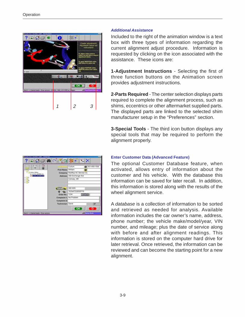
Additional Assistance
Included to the right of the animation window is a textbox with three types of information regarding thecurrent alignment adjust procedure. Information isrequested by clicking on the icon associated with theassistance. These icons are:
1-Adjustment Instructions - Selecting the first ofthree function buttons on the Animation screenprovides adjustment instructions.
2-Parts Required - The center selection displays partsrequired to complete the alignment process, such asshims, eccentrics or other aftermarket supplied parts.The displayed parts are linked to the selected shimmanufacturer setup in the “Preferences” section.
3-Special Tools - The third icon button displays anyspecial tools that may be required to perform thealignment properly.
Enter Customer Data (Advanced Feature)
The optional Customer Database feature, whenactivated, allows entry of information about thecustomer and his vehicle. With the database thisinformation can be saved for later recall. In addition,this information is stored along with the results of thewheel alignment service.
A database is a collection of information to be sortedand retrieved as needed for analysis. Availableinformation includes the car owner’s name, address,phone number; the vehicle make/model/year, VINnumber, and mileage; plus the date of service alongwith before and after alignment readings. Thisinformation is stored on the computer hard drive forlater retrieval. Once retrieved, the information can bereviewed and can become the starting point for a newalignment.
1 2 3

3-10
Operation
Adding Customer Information
Using the pointing device or TAB key to move aroundeach of the text blocks, the operator enters informationabout the customer and his vehicle using the keyboard.Selecting OK will save the record to file for laterretrieval.
Selecting a Stored Record
Stored or existing records can be sorted and retrievedin several different ways – drill down through datarecords, sort alphabetically by last name, by telephonenumber, and by vehicle license plate number. Oncea record is visible, clicking on the plus sign expandsthe list to bring up a particular data set. Another wayto find a record is to select the first letter of thecustomer’s name and highlight it using the pointingdevice. Double click with the left button when thedesired record is highlighted. The complete recordwill be displayed with stored data.
Recalling a Previous Alignment
Once a particular record under the customer is chosen,the results of that previous alignment are recalled usingthe “Recall” button (F11) on the toolbar. The firstscreen that appears is the specifications of the vehiclethat was aligned. Pressing OK brings up the InspectionScreen so that any inspected items can be reviewed.Pressing OK from here brings up the alignmentreadings in the “All Readings” format. The displayedvalues can be toggled from the initial to final readingsusing the Toggle button (F9) on the toolbar.
Adding a New Customer
Clearing all information on the data window can entera new record. Selecting Clear Fields on the toolbar(F7) clears information. Once the screen has beencleared, enter the new customer information asdesired. If another record is desired for an existingcustomer, highlight his name as using the pointingdevice, and begin entering information at the blankscreen.

3-11
Operation
Editing an Existing Record
An existing record can be edited by selecting thedesired customer record. Once the record isdisplayed, move between information fields with thepointing device or TAB key. When the “I” bar is withinthe field to be edited, make the desired corrections.Data is saved when “OK” is entered.
Using the Database Outside the Aligner Platform
The database is stored on the hard drive in a file calledAlignmentData.mdb. This database file is compatiblewith several common database programs such asMicrosoft® Access® (not supplied). See your officecomputer software representative for informationregarding these programs.
Inspection
Inspection reports are a valuable tool for the reportingof vehicle problem areas. Reports can be printed andretained for shop files or given to the customer toreinforce his comprehension of the work performedor the work necessary before an alignment can beperformed. In many cases worn or damagedcomponents will affect the quality of the wheelalignment.
A Wizard procedure can contain up to six vehicleinspection reports or lists. These lists can be selectedwithin the Wizard process or they can be selectedmanually from the Main Alignment tab.
Areas to be inspected within each of the inspectionforms are topically related. Any number of inspectionscan be utilized during the alignment process. The sixinspection forms are:- Pre-Alignment Inspection- Tire Inspection- Brake Inspection- Under Car Inspection- Under Hood Inspection- Courtesy Inspection

3-12
Operation
Using Inspection Reports
All inspection reports require the same operatingprocedures, with the exception of Tire Inspection.When the desired inspection report is displayed, usethe pointing device to select “Checked”, “Adjusted”,or “Replaced” in the column to the right of thecomponent description. A comment relating to thecomponent or repair can be typed in the spaceprovided to the right by selecting Edit Comments onthe toolbar (F8). After all inspections and commentshave been made, choose “OK” to save these checksto the database and to the printer buffer for laterprintout. Selecting “Cancel” button takes the operatorto the previous screen.
Perform Runout Compensation
Compensating for the amount of runout of the wheelassemblies is an important factor in the alignmentprocess. If not correctly determined, there will be errorsin the displayed camber and toe angles. The alignerutilizes a runout procedure that calculates a true planeof the wheel assembly by measuring variations in toeand camber planes during a 360-degree rotation ofthe wheel.
To perform wheel runout, raise the vehicle wheels offthe alignment rack surface using air jacks or othermethod to allow the wheels to rotate freely. Ananimation of how to perform runout is launched byselecting Animate on the toolbar (F5). Follow steps Athrough C carefully.
A. Turn the wheel until the stamped-in number “1” isshowing on the wheel-clamp center slide which isat the 9 o’clock position. Level the sensor, hold theassembly here and press the “Runout” key on thesensor keypad.
B. Turn the wheel until the stamped-in number “2” isshowing on the wheel-clamp center slide (180deg) which is at the 3 o’clock position. Level thesensor, hold the assembly here and press the“Runout” key on the sensor keypad.

3-13
Operation
C. Turn the wheel until the stamped-in number “3” isshowing on the wheel-clamp center slide (90 deg)which is at the 12 o’clock or straight-up position.Level the sensor, hold the assembly here andpress the “Runout” key on the sensor keypad.
After the first time the runout button is pressed a lightwill appear on the “Runout” key on the sensor,indicating the aligner is in the runout mode. As therunout key is pressed at position 2, the light will blinkand a tone will sound from the console.
At position 3 the light will blink and then go off,indicating the runout process is complete for thatwheel. If the runout indicator light does not go outafter step 3, something has gone wrong. Press therunout key until the light goes out, then repeat thecomplete the 1-2-3 runout steps for that wheel.
Repeat the above steps for all wheels.
Runout Status
The Runout screen shows the status each wheel ofthe vehicle. As runout is successfully completed eachwheel turns to a green color and display “OK”. If amoderate amount of wheel runout is detected (.75°-1.5°), but not enough to influence the alignmentresults, a “?” will appear and the wheel indicator willturn yellow. It is acceptable to continue at this point.If a high amount of runout is detected (above 1.5°), ared universal “Cancel” will appear on the wheelindicator. This problem must be corrected prior toproceeding. Incorrect wheel clamp mounting, a bentclamp, a bent or loose wheel, or a problem inside themeasuring sensor can cause excessive runout.

3-14
Operation
More Information on Runout
Here are some important notes regarding runoutcompensation:
- If “two sensors” has been selected in the Systemsetup, only two wheels will be shown.
- Runout can be completed or updated at any timeand from any screen in the aligner. It is not necessaryto start over if runout needs to be taken again. Anytime a wheel is removed from the vehicle, or theclamp is removed from the wheel, runoutcompensation must be repeated on that wheelonly.
- The wheel clamp must remain in the straight upposition (#3) at the end of the runout procedure.Do not rotate the clamp away from straight up forany reason. Be careful of many rear wheel and 4wheel drive axles where turning one raised wheelcauses another to move.
- Do not skip or shortcut the runout compensationprocess in any way. It is an important part ofobtaining accurate alignment angles.
After runout compensation is completed on all thealigner is ready to measure the vehicle’s wheelalignment angles, beginning with caster. Click on theOK button to proceed.

3-15
Operation
Lower Wheels and Bounce (settle) the Suspension
The next screen that appears instructs the technicianto lower the wheels and bounce or settled thesuspension so the vehicle sits at a true ride height.Slip plates should be utilized to provide the necessaryside-slip required to return the vehicle to its normalresting position. When lifted, a vehicle’s suspensionand steering components are placed in an unloadedcondition. If not bounced or allowed to settle whenlowered, this could skew the readings results. Clickon “OK” to proceed.
Center the Steering
If the front wheels are not facing straight ahead, thefirst step of the caster sweep directs the operator tosteer as needed. While viewing the on the screenmeter, center the steering as instructed.
Perform Caster Turn
The caster angle is measured by moving through a20-degree turn of the front wheels. The softwareguides the operator through the steps on-screen. Thecaster sweep screens show a graphic of the wheelswith the direction they should point, an arrow to indicatethe turn direction, and a steering wheel graphicindicating the turn direction. Always follow the arrowdirection and hold the wheel steady until the wheelturns green and the screen advances.
Automatic or Manual Caster Sweep
Automatic caster sweep is used in most situations,using the sensors’ infrared optics system to accuratelymeasure 10 degrees and then automaticallyprogressing to the next step. If the automatic modecannot be used for any reason, the system can beswitched into the Manual caster sweep mode whereturntable scales are used to determine 10 degreesand the OK button is pressed to move to the nextstep. The Automatic/Manual mode is selected anytimeduring the caster swing procedure by selecting theTab button on the toolbar (F5). The active selectedmode will be indicated in the top left of the display.

3-16
Operation
Turn to 10 Degrees Left
After starting out with the front wheels facing straightahead, the screen will change to indicate a turn to 10degrees left. As the turning angle nears 10 degreesthe wheels will change from gray to green meaningthe measurement has been taken.
Turn to 10 Degrees Right
The screen then changes to indicate a turn paststraight-ahead to 10 degrees right. The “wheels” willbehave as above as the 10 degree angle isapproached. The wheel graphics change to green asthe measurement is taken.
Turn Wheels Straight Ahead
The screen then changes to indicate turning thewheels to the straight-ahead position. Centering thesteering allows the geometric centerline to beestablished for the rear readings that in turn willdetermine the thrust angle or rolling direction.
Once these steps are completed, caster is measuredand the software moves to the readings screens.
Information about Caster Accuracy
There are a number of reasons why castermeasurements may vary when repeated:- Pulling/pushing the wheel differently – these
variations can be minimized by utilizing a brakepedal depressor during the caster sweep to ensurethe wheels do not roll or rock during the turns. Inaddition, utilizing the steering wheel to make theturns minimizes the operator influence.
- Failure to reach the 10 degree mark exactly and holdsteady until the measurement is taken
- Vehicle suspension / steering variations – if thevehicle has play or looseness in suspension and/orsteering components, this can affect the reactionand tilt of the wheel during turns.
- Turntable / Rack condition – the condition of theturntables is critical. They must be free moving andflat with all bearings in place. Also, center the vehiclewheels on the turntables to ensure flatness duringthe turn.

3-17
Operation
Vehicle Sensitive Alignment (VSA)
If “Vehicle Sensitive Alignment” is activated in the pref-erences menu, the message to the left will appear.Select “Yes” if this feature is desired or “No” if standardalignment procedures are desired. The “VSA” feature inmost cases will speed the alignment process by skippingprocedures not required for completion of the alignment.
The VSA procedure is activated by selecting “PromptWhen Available” on the “Features” menu, under thePreferences tab. See illustration to the left.
Calibration Check
Each time the aligner is operated it checks itself againsta preprogrammed set of parameters and determines ifthe machine accuracy has been compromised. First,all measuring sensors must be level. A screen indicateswhich sensors require attention. Once level is achievedon all four sensors, a verification screen indicates which,if any sensors exceed calibrated parameters. Thisfeature will warn the operator if readings will be affectedif a sensor has been dropped or damaged.
Vehicle Dimensions / Setback
The results of the 8-sensor vehicle dimensionsmeasurements are displayed with a visual referenceto a vehicle depicting wheelbase difference, trackwidthdifference, and front and rear setback. Setback occurswhen one wheel on an axle is not even with the other.
Setback and vehicle dimensions are usefulmeasurement tools to diagnose vehicles that mayhave been involved in a collision.

3-18
Operation
All Readings
This is a screen that shows both the rear and the frontreadings at the same time, giving the ability to evaluatethe vehicle’s total alignment status. If vehiclespecifications have been entered, the numeric displayswill be red (out of specification) or green (withinspecification). Front and rear camber and toe readingsare live on this screen allowing for adjustments to bemade. In addition, this screen is where the vehicle’sdiagnostic angles, if measured, are displayed. Theseangles are Included Angle, SAI, Toe Out on Turns,and Setback. Click on the scroll bar to the right of thescreen to view the diagnostic angles for the front andrear.
Rear Readings
After All Readings, the Rear Readings screen appears.This screen displays, both in meter and numericalformat, the angle measurements and informationneeded to determine if corrections are necessary. Thedisplay is divided into three rows: Camber, Toe andThrust Angle. The columns represent the left andright side of the vehicle. The Camber and Toe metershave minimum and maximum specifications along thetop, a numeric readout of live readings, and a colorcoding to indicate the relationship of live values tospecification. Grey meters indicate no specificationhas been entered for this angle. Red meters indicatethe angle is beyond manufacturer’s specification.Green meters indicate the live values are within thespecification. Elevated readings can be viewed byselecting the “Jack” icon located right of the crossvalues.
Cross Values / Total Toe
The numeric value between the camber metersindicates cross values (side-to-side), the differencebetween left and right readings. This cross value isimportant on many vehicles for proper handling. Thenumeric value between the left and right toe metersindicates the rear Total Toe (the sum of individual toe).

3-19
Operation
Readings Toolbar
Toolbar buttons available on both front and rearReadings Screens from left to right are:F1 Help – displays operation assistance for the screen
presently openF2 Meters - takes the user directly to “Readings”F3 Home – returns the software to the opening Home
Alignment tabF4 Print – accesses the print report menuF5 Measure – access to measuring additional anglesF6 Adjust – access to assistance for the technician
with angle correctionsF7 Animate – assists the technician with illustrations
of each angle adjustmentF8 Zoom – brings any meter to full screen size to aide
viewingF9 Wizards - change wizardsF10 Login – user Login or LogoutF11Edit – allows editing of the vehicle selection,
specifications, customer information, andinspections within the current alignment
F12 Setup – allows alteration of any setup item on thePreferences tab
NOTE: If a toolbar button is “grayed out” it meansthe function is not available on thatparticular screen.
1 2 3 4 5 6 7 8 9 10 11 12

3-20
Operation
Level and Lock Steering Wheel
Before front readings are displayed it is necessary tolevel the steering wheel and lock it in place using thesteering wheel holder. In addition, all measuringsensors must be leveled and locked in place. Press“OK” to move forward.
When the aligner software prompts the operator tolevel the steering wheel, the vehicle’s thrust angle isdetermined. Thrust Angle is the direction of thevehicle travel determined by the total toe of the rearwheels. The thrust angle is used as a referencewhen adjusting the front toe so that a straightsteering wheel is the end result. Toe error on manyrear wheel drive vehicles cannot be corrected,creating a dog tracking effect and/or a crookedsteering wheel.
Front Readings Screen
The Front Readings screen is similar to the rear. Casteris displayed with the top meters. Note this reading isrepresented by an icon showing the caster reading tobe “frozen”, since caster is not a live reading. Cambermeters are located in the middle of the screen andtoe meters are at the bottom. Camber and toe are“live” displays which can be referenced while makingadjustments. When measurements are withinspecification, the center portion of the meter is green.If red is displayed, the readings are outside ofspecifications. Grey meters indicate this angle hasno specification. Elevated readings can be viewed byselecting the “Jack” icon located right of the crossvalues.
Cross Values / Total Toe – the numeric value betweenthe caster and camber meters indicates cross values(side-to-side), the difference between left and rightreadings. This cross value is important on manyvehicles for proper handling. The numeric valuebetween the left and right toe meters indicates thefront Total Toe (the sum of individual toe).

3-21
Operation
Loop Button
There are three “Readings” screens within the software– All Readings, Rear, and Front Readings. Thesethree screens can be “looped” from the Front Readingsscreen. When the Front Readings screen is displayed,the Rear and All Readings screens are retrieved bypressing the “Loop” button located at the lower leftcorner of the screen.
Zoom
For a full screen zoom image of any one meter movethe white highlight box with the arrow keys, and thenselect Zoom on the toolbar F8. Click on button F8again to return to the full screen display (unzoom).Double-clicking on any meter will also zoom/unzoomthem. It is possible to move around to other meterswhile zoomed by using the arrow keys on the keyboardand sensor keypads.
Print Results
Select Print on the toolbar (F4) on either the Front orRear Readings screen to go to the Printer Menuscreen. The options are:
1-Select Desired Alignment Report - Select thedesired type of report to be printed from the drop downbox
2 - Import from a disk - This selection allows acustomized report or logo to be imported to the systemdirectory. Custom reports must be created by CrystalReports* by the user or authorized agent. A custom“BMP” logo can be imported as well.
3 - Set Default Report - Determine the desired reportto be used as default and for one click printing.
4 - Zoom - Select this button to enhance the size ofthe displayed report. Click OK to continue printing orCancel to go back to the print menu.1 2 3 4
* Not included with aligner software package

3-22
Operation
InspectionsInspections are typically part of the Wizard process,or can be selected from the Home Alignment tab byclicking on the Inspection icon. In addition, Inspectionscan be accessed during the alignment from thereadings screen by selecting the “Edit” button (F11)on the toolbar. The single icon on the right side,Vehicle Dynamics, accesses the diagnostics functionsof the aligner.
MAPThe MAP button, located on the lower left of theInspection screen, launches vehicle inspection andrepair information from MAP, which stands for MotoristAssurance Program. This information providesguidelines for the automotive service industry on howto diagnose faulty components and the proper waysto explain the needed repairs to the vehicle owner.This is a valuable tool for the industry that has beenwidely accepted throughout North America.
Vehicle DynamicsIf additional assistance is required to repair or diagnosean alignment problem, the technician has severaloptions that he can exercise. Diagnostic proceduresare available automatically when programmed into aWizard or they can be accessed when needed duringan alignment.
From the Inspection screen, click on the VehicleDynamics icon to bring up the Vehicle Dynamicsscreen. Two icons are available – Manual andAutomatic Diagnostics.

3-23
Operation
Manual DiagnosticsSelection of Manual Diagnostics activates a seriesscreens in which the operator is asked questions toassist the technician in diagnosing the vehicle’sproblem. When all questions have been answered,suggestions in resolving the problems are made.
Four complaints are covered – Pull, Unlevel SteeringWheel, Vibration, and Treadwear.
Automatic DiagnosticsSelecting Automatic Diagnostics activates a routinethat utilizes measured angles, compares them tovehicle specifications, then makes an determinationof a vehicle’s potential problem. This feature is usefulfor educating the technician and vehicle owner on whatvehicle problems are created when alignment anglesare out of specifications. The screen shows theexpected vehicle problem for caster, camber, and toeon the left and right wheels.
Note: The operator must measure SAI and mustenter specifications before an automaticevaluation can be made. If theseDiagnostics screens are made part of thealignment path using a Wizard, it isrecommended to configure the “AlignmentOrder” to measure Caster/SAIsimultaneously instead of caster only.
Bent Parts DiagnosisSAI, Included Angle, and camber have been usedmanually for years to diagnose bent parts. Thistechnique has been incorporated into the softwareutilizing the power of the computer system. Anglesare measured and compared with vehiclespecifications to determine if a problem exists. An on-screen readout informs the technician whichcomponents are most likely bent or damaged,categorized by suspension designs.

3-24
Operation
MeasureWhen the Measure icon is selected from the MainScreen or from the toolbar on any readings screen, ascreen appears that allows the operator to measureany wheel alignment angle.
1-Caster Only – used to update the caster value byre-sweeping the wheels through the 20 degree turn.
2-Caster and SAI on Turntables – measures boththe caster and steering axis inclination (SAI) anglessimultaneously by sweeping the wheels through the20 degree turn. This is done on the turntables (loadedsuspension)
3-SAI Only Elevated – measure the SAI angle only,with the wheels elevated (unloaded)
4-Camber at Zero Toe* – a routine that forcesmeasurement of camber with each individual wheelin the straight ahead (zero toe ) position.Recommended for vehicles with high caster values
5-Vehicle Dimensions – provides additionalinformation about the condition of the vehicle’s frame,such as setback. With the optional 8-sensormeasurement package, additional information, suchas trackwidth difference, is displayed
6-Toe Out On Turns – measure the difference inturn angles of the front wheels at 20 degrees (toe outon turns)
7-Maximum Turn Angle – measure the maximumangle each front wheel will turn
8-Toe Curve Measurement* – measure the individualwheel toe change as the suspension goes throughbounce and rebound
9-Ride Height Measurement* – measure the vehicleride height
* These Measurements are Premium Features
9
1 2 3 4
5 6 7 8

3-25
Operation
Steering Axis Inclination (SAI) and Included Angle(IA)These angles are powerful tools in diagnosing bentor damaged suspension parts. A bent spindle, controlarm, strut, frame mounts, or a cradle shift problemscan be identified. SAI is measured either vehicleweight loaded on the turntables or with the front wheelselevated. Included Angle is not actually an angledefined on the vehicle – it is a mathematical formula.By definition, IA = SAI + CAMBER. Most latemodel vehicles have a specification for Included Angle,and a few for SAI. Co mpare the measured values tospec, but also compare side-to-side (cross)differences.
Note: Cross differences for Included Angle shouldnot exceed 1 to 1.5 degrees for mostvehicles. If a high cross value is discovered,it may be creating a pull condition.Generally, the damaged part is on the sidewith the lower IA reading.
Measuring Steering Axis Inclination (SAI) andIncluded AngleThe measurement method for SAI and Included Angleis similar to the Caster measurement. The wheelsare turned through a 20 degree turn and the changein wheel tilt is measured. SAI can be measured eitheron the turntables (loaded) or with the front wheelselevated (unloaded). The results of loaded or unloadedwill be similar, but some variation may occur due tothe type of vehicle suspension. When measured onthe turntables, caster is also measured. For accurateresults follow the on-screen instructions carefully.
1. Whether measuring SAI on the turntables orelevated, it is mandatory to lock the vehicle’sbrakes. Start the car to initiate the power brakesand install the brake pedal depressor between theseat and the brake pedal.
2. Level and lock the measuring sensors on thewheel clamps using the locking knobs.

3-26
Operation
3. Follow the on-screen instructions. During theelevated measurement, the instruction say to raisethe front wheels using rigid supports. This istypically done with a jack included with the alignmentlift.
4. The turning sequence is identical to the process forobtaining caster values.
5. When measuring elevated SAI, the final instructionswill be to lower the vehicle and bounce thesuspension.
6. The SAI and Included Angle values are displayedon the All Readings screen. Caster is displayed onthe All Readings screen as well as the FrontReadings meter screen.
7. Use SAI and Included Angle to diagnose a handlingproblem or a bent part that is limiting the adjustmentof camber.
Note: Not all vehicle manufacturers publishspecifications for SAI or Included Angle. Allavailable manufacturers’ specifications areincluded in the aligner database.
Camber at Zero ToeThis routine measures camber on the left and rightfront wheels individually at zero toe. This is therecommended procedure for vehicles with high casterspecifications, such as Mercedes-Benz.
The procedure is as follows:
1. Select Camber at Zero Toe from MeasureScreen
2. Using the on-screen meter, turn the left wheeltowards the center until the meter turns green
3. Press OK to continue4. Repeat this process for the right wheel. Click OK
to continue5. The software returns to the readings screen

3-27
Operation
Vehicle Dimensions / SetbackSetback and vehicle dimensions are usefulmeasurement tools to diagnose vehicles that mayhave been involved in a collision. Setback occurswhen one wheel on an axle is not even with the other.These measurements are accessed from the Measuretoolbar button on the Front or Rear Readings screens,or from the Measure icon on the Home Alignment tab.In addition, Vehicle Dimensions can automaticallyappear in the alignment path if this feature has beenset up in the Wizard procedures. On-screeninstructions must be followed carefully.
The results of the 8-sensor vehicle dimensionsmeasurements are displayed with a visual referenceto a vehicle depicting wheelbase difference, trackwidthdifference, and front and rear setback. In addition,setback values are displayed on the All Readingsscreen and are printed during the alignment resultsprintout. Vehicle dimensions and setback can bedisplayed in inches or millimeters, selectable in theUnits setup.
Toe-Out-On-Turns (or Turning Radius)Toe-out-on-turns is another diagnostic measurementthat is valuable in troubleshooting steering andhandling problems.
TOOT or turning radius, as it is commonly called, isthe difference in the turning angle between the insideand the outside wheel.
On many vehicles, the manufacturer specifies theinside wheel to be turned 20 degrees. Other vehiclesspecify the wheel be turned to a different angle. Thisis possible by clicking on the “Other Angle” button andspecifying the reference angle.
Note: The vehicle database does not containspecifications for toe-out-on-turns. Refer toan alignment specification book or thevehicle’s shop manual.

3-28
Operation
The Toe-Out-On-Turns measurement entry isautomatic using the CCD toe imaging sensors. Somesystems may also be equipped with optional ElectronicTurntables for extended range.
Turn the inside wheel to the reference angle asindicated by the scale, the values are entered into thecomputer automatically when OK is selected. Whena turn is made to the left, the driver side wheel is theinside wheel and the passenger side is the outsidewheel. Repeat these steps for a right-hand turn. Thediagnosis of a problem is always made on the outsidewheel of the turn. For best results follow the screenscarefully. Once completed, the TOOT results appearon-screen in a chart format and are available forprintout. To review the TOOT values later in thealignment, go to the All Readings screen.
Note: Toe Out on Turns problems indicate a bentor damaged steering arm, with the problemwheel being the one on the outside of theturn.
Maximum Turn AngleThis routine is very similar to the Toe Out On turnsfeature. It allows the measurement of the “full lock”or maximum turn in each direction. It uses theturntable scales and provides the ability to enter theresults in the computer for viewing and printing.Consult an alignment specification manual or shopservice manual for manufacturer specifications for themaximum turn reference angle and the outside turnvalue. Entry of these values is accomplished byclicking on the up or down arrow button next to thenumeric window until the desired value is obtained.

3-29
Operation
Toe Curve ChangeThis feature allows measurement of individual wheeltoe change as the suspension system goes throughbounce and rebound (spring compression andexpansion). An excessive amount of toe change cancause premature tire wear. A large change on onlyone side can cause “bump steer”, a dangerouscondition causing the vehicle to rapidly changedirections when bumps are encountered. While thereare no specifications for the amount of change, itshould be fairly small, and a comparison of left andright wheels can assist in diagnosing defective steeringsystem components. Follow the on-screen instructionscarefully to move the suspension through a 60mm(2.3”) travel. Pulling down or pushing up thesuspension can do this. Use a ruler or tape measureto observe the proper amount of frame movement.Select OK when completed to display the results.
Note: On cars with rack and pinion steering, abump steer condition is usually created byworn rack mounting bushings that allow theentire rack to shift when bumps are hit.Some cars have slotted idler arm mountsto allow correction of toe curve changeproblems.
Ride HeightThe alignment of many vehicles are dependent on aride height measurement. Variations in ride heightmay alter desired specifications. Examine the ve-hicle and determine the proper method of ride heightmeasurement. Highlight the measurement methoddisplayed for both front and rear. Press “Enter”.
Input the measured values into the provided spacesto record into the database
Many vehicles may not have manufacturers rideheight specifications, however the side to side andfront to rear relationship can be measured andcompared to diagnose a potential problem.

3-30
Operation
AdjustOne of the most powerful features of the software isassistance given to the alignment technician whenperforming adjustments on a vehicle. These features areon the Adjust screen, and are accessed through the Adjusticon, located on the Home Alignment screen and fromthe Adjust button on the toolbar when alignment readingsare displayed.
There are numerous features designed to improve theefficiency and affectivity of the alignment technician. Iconchoices are from the Adjust screen are explained below:
1-Caster and/or Camber – several different optionsavailable to assist with these angles, including live casterand elevated modes
2-Adjust A-arms – for vehicles whose caster and camberadjustments are located on the suspension A-arm, thisselection allows both angles to be correctedsimultaneously
3-EZ Toe* – this software routine is a new and improvedmethod of setting front toe, making it easier to obtainstraight steering wheels
4-Cradle Adjust* – assist with the adjustment of theengine cradle on many front wheel drive cars
5-Drag Link Adjust* – assists with steer direction andstraight steering wheel when performing toe adjustmentson trucks with a drag link adjustment
6-Single Tie Rod Adjust* – helps with vehicles havinga single tie rod toe adjuster
7-Shims and Kits – many front wheel drive cars use ashim on the rear axle/spindle to adjust camber and/or toe.This program determines the proper shim to use
8-Front Shims and Kits – used on many 2 and 4 wheeldrive trucks to calculate proper size and orientation ofoffset bushing or sleeve
9 - ADR Adjustment* - The aligner can be used inconjunction with VAS 6141 to align the ADR sensor to thevehicle thrust line.
* These Adjustments are Advanced Features
5 6 7 8
9
1 2 3 4

3-31
Operation
Live Caster, Camber and ToeThese selections access methods of adjusting caster,cameber and toe with live readings. The user selectedicon will depend on the type of adjustment being madeand the type of vehicle suspension.
1- Adjust Caster, Camber, Toe on Turntables –Caster, camber and toe adjustments can be made withthe suspension loaded, such as cams on a McPhersonstrut for camber or strut rods for adjusting caster. Inthis mode, the wheels remain on the turntables andcaster is a live reading.
2- Adjust Caster, Camber and Toe Elevated – Theweight of the vehicle may keep the adjustment frombeing made easily, such as moving the upper strutmount. In this mode, the wheels are elevated andcaster is a live reading.
3- Adjust Caster, Camber, Toe Wheel Off - Thisselection is like selection (2) above except the operatoris given the choice of mounting the measuring sensordirectly to the brake rotor for easy access to adjustmentcomponents. Refer to page 3-3 for more information.
Elevated Camber and Toe4- Adjust Front Camber and Toe Elevated – thismode is used for adjusting camber and toe on thefront wheels. The readings on the turntables areretained even though the wheels are elevated.
5- Adjust Caster, Camber, Toe Wheel Off - Sameas above but with the Wheel-off option.
6- Adjust Rear Camber and Toe Elevated – thismode is used for adjusting camber and toe on therear wheels. The readings on the turntables areretained even though the wheels are elevated.
7- Adjust Caster, Camber, Toe Wheel Off - Same asabove but with the Wheel-off option.
1 2 3 4
5 6 7

3-32
Operation
Adjust Caster and/or Camber, Toe on Turntables
After selecting this icon, instructions appear inpreparation for the adjustment.1. Bounce the suspension2. Install brake pedal depressor3. Level and lock the sensors
WARNING! FOLLOW ALL ON-SCREENINSTRUCTIONS CAREFULLY. INCORRECTADJUSTMENT READINGS ARE POSSIBLE IFTHESE STEPS ARE IGNORED.
When OK is pressed, a screen very similar to thestandard Front Readings display appears. The majordifference is the caster reading – it is live instead offrozen. Caster and camber can be adjusted whileviewing this screen – for example, caster change willbe shown as a strut rod is lengthened or shortened.
As the adjustments are made, the meter movementsand numeric values change. The meters are colorcoded to show their relationship to specification. Thisscreen is useful for vehicles with independentadjustments where one adjustment causes the otherangle to change (i.e. Mercedes Benz and Lexus).
Once the adjustments are completed, press OK.
1. Unlock the brakes2. Unlock the sensors3. Press OK
The software returns to the Caster and/or Camberselection screen. Select the Cancel button to returnto the meter screens.

3-33
Operation
Adjust Caster, Camber and Toe Elevated
After selecting this icon, instructions appear inpreparation for the adjustment.1. Bounce the suspension2. Install brake pedal depressor3. Level and lock the sensors4. Press OK5. Raise front wheels using rigid supports6. Press OK
WARNING! FOLLOW ALL ON-SCREENINSTRUCTIONS CAREFULLY. INCORRECTADJUSTMENT READINGS ARE POSSIBLE IFTHESE STEPS ARE IGNORED.
When OK is pressed, a screen very similar to thestandard Front Readings display appears. The majordifference is the caster reading – it is live instead offrozen.
Adjust caster and camber while viewing this screen –for example, camber and caster change will be shownas an eccentric cam is turned. As the adjustmentsare made, the meter movements and numeric valueschange. The meters are color coded to show thereadings’ relationship to specification.
Once the adjustments are completed, press OK. Post-adjustment instructions will be displayed.
1. Lower wheels. Bounce suspension2. Unlock the brakes3. Unlock the sensors4. Press OK
The software returns to the Caster and/or Camberselection screen. Pressing the cancel button fromthere returns to the meter screens.

3-34
Operation
Adjust Front Camber Elevated
Adjust Rear Camber Elevated
For either the front or rear wheels, this feature allowsthe wheels to be elevated while retaining the measuredcamber values. This gives the ability to make accuratecorrection of camber without vehicle weight inhibitingthe adjustment process. This would be useful fortapping down a wedge on a strut vehicle.
The adjustment screen displays live camber metersand numeric values for the left and right wheels alongwith live toe values. Make the desired adjustmentswhile viewing the meters. When completed with theadjustment, press OK. Post-adjustment instructionsare displayed.
1. Lower wheels2. Bounce suspension3. Press OK
The software returns to the Caster and/or Camberselection screen. Pressing the cancel button fromthere returns to the meter screens.

3-35
Operation
Adjust A-arms
Many vehicles have adjustment provisions for casterand camber located on the suspension A-arm (controlarm), either on the upper or lower arm. Theadjustments may be made with shims, eccentric cams,or slots in the frame. Both angles are easily correctedto manufacturer’s specification using the Adjust A-armicon.
The first step is telling the aligner the location of theadjustable A-arm and whether the corrections will bemade on the turntables or elevated. This isaccomplished by pressing the proper icon on theAdjust A-arm screen. The icons are:
Caster/Camber Adjustment on Upper ArmCaster/Camber Adjustment on Lower Arm
Examine the vehicle for the location of the adjusters.It does not matter whether the A-arms have shims,slots, or cams. Once the technician makes thedecision, upper or lower, on the turntables or elevated,instructions appear apply the brake pedal depressor(important).
Next, a screen appears with a graphic of the right sideA-arm along with two meters. These meters representthe movement of the front and rear of the A-arm, andtheir relationship to the desired readings. Move eachside of the A-arm by adding/removing shims, looseningthe bolts and sliding the arm, or turning the eccentriccams, until each meter indicator is centered in themeter – this is the desired value for both caster andcamber. Press OK when this side is complete – asimilar screen appears for the left side. When bothsides are completed, press OK to return to the Adjustscreen, and Cancel to go to readings.

3-36
Operation
EZ ToeThis software routine is an improved method of settingfront toe, making it easier to obtain straight steeringwheels. It also makes it possible to adjust toe withthe wheels turned left or right, an aide when settingtoe on cars with firewall-mounted rack and pinion units.
Use the following procedures:
1. Perform all alignment steps normally used to obtainalignment readings. Correct any misalignment inthe rear as well as front caster and/or camber.
2. Select the EZ Toe icon from the Adjust screen.
Note: DO NOT use the Steering Wheel Clampduring the EZ Toe procedure.
3. Level the vehicle steering wheel and the measuringsensors. Select OK.
4. Steer the right wheel to desired adjust position.Select OK.
5. The next screen shows a meter indicating theamount of toe change needed for the right wheel.
6. Adjust the right tie rod until the meter needle is inthe green. Select OK after completion.
7. Follow the same procedures for the left wheel.
8. Select OK once the left toe adjustment is made.
9. Return to the Front Readings screen and rechecktoe and steering wheel position.

3-37
Operation
Cradle Adjust
Cradle adjustment is a growing necessity for frontwheel drive vehicles. Many front wheel drivevehicles are designed where the engine cradle alsoserves as the attachment point for the lower pivotsof the suspension system. This assembly is boltedto the sub-frame as a unit from the bottom of thevehicle. The assembly must be properly alignedwith the sub-frame to assure that front alignmentis maintained.
A closer look shows that the lower control armsare bolted to the engine cradle. The control arm isattached to the spindle through the lower ball joint.The strut is attached to the top of the spindle andis then attached to the body via the upper strutmount to complete the suspension steering axis.
The engine cradle can potentially move side to side,changing the camber and SAI angles. Prior tobeginning a cradle adjustment, examine the left andright camber values. If one side has excessivepositive camber and the other side excessivenegative, this vehicle is a candidate for cradleadjustment.
Vehicles with possible cradle misalignment include:Ford Taurus / Mercury Sable, Lincoln Continental,GM “W” Body (Lumina, Grand Prix, Cutlass, Regal),Chrysler “LH” Body (Intrepid, Vision, Concorde,LHS), Honda Accord, Acura Integra, Mazda 929.
Consult the specific vehicle service manual fordetails on how to loosen the engine cradle.
To adjust a cradle, click on the Cradle Adjust iconon the Adjust Screen. The Cradle Adjust screenhas a graphic of the cradle with an arrow showingthe direction of needed movement. A meter displaydetermines exact placement. Loosen the cradleand slide in the direction of the arrow until the meterindicator is straight up – this is the ideal placementof the cradle. In addition, a live caster reading isshown for reference or for making a minor castercorrection.

3-38
Operation
Drag Link Adjust
The steering linkage on some 4-wheel drive truckshas a single total toe adjuster along with a drag linkadjuster to correct the steering direction and straightenthe steering wheel. The Drag Link Adjust feature allowssimple and accurate adjustments to be made. Fromthe Adjust Screen select the Drag Link Adjust icon.
The Drag Link Adjust screens displays a total toe meterand a steering direction meter. To make the properadjustments use the following steps:
1. Steer the front wheels to equalize toe by bringingthe lower meter into the green area. Click OK.
2. Adjust the single tie rod to the total toe specificationswhile observing the upper meter. Click OK.
3. Straighten and lock the steering wheel as promptedthen click OK. Adjust the drag link sleeve until thesteering direction is straight ahead, as indicatedon the lower meter display.
Single Tie Rod AdjustSome vehicles, such as earlier Ford trucks and 80’sVolkswagons, have a single tie adjuster for total toe,with no provision for adjusting for straight steeringdirection with a straight steering wheel. For thesevehicles, click on the Single Tie Rod Adjust icon.
The screen that appears is similar to the Drag LinkAdjust screen. Use the following steps:
1. Steer the front wheels to equalize toe by bringingthe lower meter into the green area. Lock thesteering wheel at this position.
2. Adjust the single tie rod to the total toe specificationswhile observing the upper meter.
3. If a straight steering wheel does not result, yet isdesired, remove the steering wheel from thesteering column (see factory recommendedprocedures prior to removing) and replace it asneeded for a straight condition.

3-39
Operation
Shims and Kits
Many front wheel drive vehicles utilize aftermar-ket shims to correct front and rear camber and/or toe. This correction is achieved by placing theshim between the rear axle and the spindle.
When a vehicle that utilizes rear shims is accessed from thespecification database, the technician can use the aligner todetermine the proper shim to correct a rear misalignment.From the “Adjust” screen choose the Rear Shims and Kitsicon.
At this point the computer will examine the live rear camberand toe readings, compare them to preferred specification,and calculate the amount of change needed. It will thenrecommend the shim needed to make this correction. Thescreen to the left will be displayed.
Default Part VendorDetermine the desired part vendor to select asthe default aftermarket supplier. This selec-tion will vary location to location and upon theTechnicians preferences.
INFOThe correct part number is automatically selectedand displayed dependant on the vehicle selectedand the amount of correction required.
Highlight one of the part numbers displayed, thenclick on the “Info” ICON to invoke a screen describing thecorrect orientation of shims or other corrective aftermarketparts. The “Info” ICON can be selected from several places ofthe screen. If highlighted, information is available. See samplescreen at left.
Installation video and detailed Instructions may also be avail-able.
Click the “Aftermarket Tools Available” ICON toview tools required for the specific procedure ifavailable.

3-40
Operation
Front Offset Cam Bushings
Many pickup trucks including Ford 2-wheel drive trucksand many Ford/GM/Dodge 4-wheel drive trucks utilizeoffset sleeves, cams or inserts around the upper orlower ball joints to adjust the caster and camberangles.
The program compares the current reading for casterand camber with the preferred specification, displayingthe meters on-screen for reference. The requiredsleeve/insert to correct the angles is shown below themeters, along with the orientation of the slot. Properorientation of the slot insures the correct amount ofcaster and camber is obtained from the sleeve/insert.
The calculations assume the current sleeve/insert isa ZERO (no offset). If it is not, examine the slotorientation to determine if the previous installationcorrected camber or caster. Enter the value of the oldsleeve/insert in the box below either caster or camber,whichever most accurately reflects the orientation ofthe slot.
Note: Whenever there is a sleeve/insert installedthat is not zero, it is difficult to determineits affect on the calculation of the newrequired sleeve/insert. It is a good idea tohave a few zero sleeves available to installin the truck and remeasure caster to get atrue initial reading.
ADR Adjustment
Immediately after the vehicle is selected, the operatoris asked if the vehicle is equipped with Adaptive CruiseControl (Volkswagen Phaeton for example). Thesequence is only for vehicles with this feature. Afternormal alignment inspections and customer date en-try, the first Phaeton specific screen is the informationscreen that gives an overview of the process. Followon-screen instructions

Maintenance
4-1
Maintenance
Maintenance MenuThis screen is the hub of all service andmaintenance. Icon selections are:
1. Calibration – the software that enables themeasuring sensors to be calibrated using theoptional Customer Calibration Kit. An optional ISOcalibration fixture is also available for certifyingsystems to ISO traceable standards.
2. Measurement Data – primarily for servicepersonnel, this allows access to measuring sensordirect output.
3. Preventative Maintenance – a software featurethat guides the equipment operator throughrecommended periodic aligner maintenance.
4. Demo Mode - A program used primarily by salesrepresentatives and training personnel. This isprogram that demonstrates the capabilities of thealigner software without actually having measuringsensors or a vehicle available. It is a useful toolfor training new or experienced users aboutmachine features.
5. Windows Utilities – Allows access to theWindows Desktop and also allows the operatorto perform routine installation of printers, software,etc.
6. Database Utilities – The feature is used forbacking up and restoring alignment based datafiles, customer data, etc.
7. Speaker Training – Optional Hardware /Software package that allows an end-user tocontrol the aligner through voice commands.
1 2 3
4 5 6 7

Maintenance
4-2
Calibration Menu
Camber/SAI/Cross Toe Calibration
Calibration of the measuring sensors requires theCustomer Calibration Kit. This kit consists of a steel-tube bar approximately 5 feet long and a pair of stands,(with screw/knob assemblies). Make sure these itemsare present before proceeding with the calibration. Thereare three separate subsystems that must be calibrated– cross toe, track toe, and camber/SAI sensors. Crosstoe measures wheel angles across the front or back ofthe vehicle. Camber and SAI sensors measure wheeltilt angles. Cross toe and Camber/SAI and Track toecalibration is performed by placing the sensors on thecalibration bar and stands. Each sensor has a toe systemthat measures angles from the front to rear.
Calibration Factors
The calibration factors can be viewed at anytime byselecting the Calibration Factors icon from the CalibrationMenu. These factors are referenced each time analignment is performed. Notice there are three sets ofcamber factors for the three alignment surfaces.
Calibration HistoryThe past 10 calibrations of the Aligner can be viewed byselecting the Calibration History icon on the CalibrationScreen. It gives a graphical presentation of the calibrationfactors of any sensor selected, allowing a visual trackingof any problem areas. Selecting any of the buttons belowthe sensor selection brings up the calibration informationfor all 4 sensors, along with dates the calibrations wereperformed.
The calibration history displays the last 10 calibrationsperformed on the aligner. The chart is graphed, the Xfactor is numbered 1 thru 10 (last 10 calibrations) 1 beingthe calibration just performed and the Y factor isnumbered -2.0 thru +2.0 (Raw Data).
By selecting the radio button under the “Sensor” the unitwill return a graph for that Wheel Sensor and display thelast 10 calibrations for each component inside the wheelsensor. The operator also may view any notes that mayhave been entered by selecting the buttons in the lowerhalf of the screen. Each time a calibration is performedthe 10th calibration history and notes are purged andthe history is moved 1 becomes 2 and 2 becomes 3 andso on up through 10.

Maintenance
4-3
ISO CertificationThis purpose of this procedure is thecalibration certification procedure for theImaging family of wheel alignment products,using traceable measurement standards andISO methods.
This procedure may optionally serve as a fine tuning ofthe calibration by allowing offset values to be applied.
The basic alignment system calibration is performed usingthe service calibration functions normally performed bythe Service Representative but can be performed by auser if an optional calibration kit is purchased.
The procedures tend to certify the calibration of the CCDbased wheel alignment products. The aligner will becertified for accuracy using an apparatus consisting ofaxles, stands, and spacers, which are themselves certifiedannually. All inspection findings regarding the aligner,will be annotated on the Certificate of Calibration.
The certification frequency can be a customer-defined.The certification will alert the user at one year intervalsto recertify if not performed earlier. The customer maydetermine the calibration and certification intervalsneeded and the accuracy to be specified.
Information must be entered for the ISO calibration reportsuch as the ISO fixture serial number and the certifiedoffsets.
Information about the shop is then entered for thecertification record.
Perform the procedures as directed in the “On-line”instructions which follow.
Anytime the “ISO” icon is selected from thetoolbar the ISO report is displayed in text format.

Maintenance
4-4
Front Sensor Calibration procedures
Note: Follow all on-screen instructions carefully toensure quality results.
1. Click on the Camber/SAI Calibration icon on theCalibration screen.
2. Select whether the front or rear sensors are to becalibrated by clicking on the proper radio button.
3. Choose the rack that the calibration is to be performedon. Up to 3 alignment surfaces can be utilized, andeach must be calibrated independently. In mostshops, Rack A is the primary alignment surface –choices are Rack A, Rack B, or Floor. Each alignmentsurface can be renamed to whatever is desired. Seerenaming instructions in the “Setup” chapter.
4. Set the calibration stands on the front (turnplates) with the open end of the stands facing therear of the alignment lift. Set the calibration barinto the notched sections of the stands with thenumbers that are printed on the bar on the lefthand side. Click on the “OK” button in the lowerright hand corner.
Next step
1. Rotate the bar forward until the #4 is at 12:00.
2. Slide both the left and right front sensors into thecalibration bar with the groove on the stub shaftfacing up.
3. Hand tighten the left and right thumb screws onthe calibration bar.
4. Rotate the bar forward until the #1 is at the 12:00position.
5. Level and lock both sensors using the level vialthat is mounted on the outside shell of thesensor. This procedure automatically sets theelectronic level inside the sensor.
6. Gently press the “runout” button on one of thefront sensors.
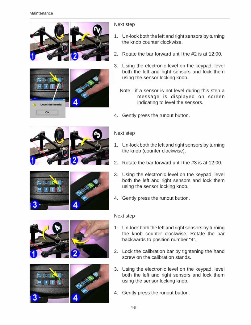
Maintenance
4-5
Next step
1. Un-lock both the left and right sensors by turningthe knob counter clockwise.
2. Rotate the bar forward until the #2 is at 12:00.
3. Using the electronic level on the keypad, levelboth the left and right sensors and lock themusing the sensor locking knob.
Note: if a sensor is not level during this step amessage is displayed on screenindicating to level the sensors.
4. Gently press the runout button.
Next step
1. Un-lock both the left and right sensors by turningthe knob (counter clockwise).
2. Rotate the bar forward until the #3 is at 12:00.
3. Using the electronic level on the keypad, levelboth the left and right sensors and lock themusing the sensor locking knob.
4. Gently press the runout button.
Next step
1. Un-lock both the left and right sensors by turningthe knob counter clockwise. Rotate the barbackwards to position number “4”.
2. Lock the calibration bar by tightening the handscrew on the calibration stands.
3. Using the electronic level on the keypad, levelboth the left and right sensors and lock themusing the sensor locking knob.
4. Gently press the runout button.

Maintenance
4-6
Next step
1. Swap the entire assembly from left to right so thatthe left sensor is on the RH side facing rearwardand the right sensor is on the LH side facingrearward. The calibration bar must also berotated so that the numbers are on the RH sideof the alignment lift.
2. Rotate the calibration bar so that the number “4”is in the 12:00 position.
3. Using the electronic level on the keypad, levelboth the left and right sensors and lock themusing the sensor locking knob.
4. Gently press the runout button.
Next step
1. Remove the wheel sensors from the bar andorient them so that both rear toe sensors arefacing each other.
2. Using the electronic level on the keypad, levelboth the left and right sensors and lock themusing the sensor locking knob.
3. Gently press the runout button.

Maintenance
4-7
Next step
After calibration a screen will appear displaying thecalibration factors of all systems within the frontsensors. The screen has three columns of numbers.The first column “New” displays the calibrationfactors that were just obtained. The second column“Current” displays the calibration factors that wereobtained from the previously performed calibration.The last column “Change” shows the total amountof change between the two calibrations. Should afactor exceed the usable limit, a warning will bedisplayed which indicates a possible problem andwill recommend that a service technician be called.Clicking on the “Cancel” button will reject the newcalibration factors and return to the CalibrationScreen. Clicking on the “OK” button will accept thenew factors and use them to perform alignments. Afourth column called “Comments” allows the operatorto enter any notes about why the calibration wasperformed.
Rear Sensor Calibration
Repeat the calibration process for the rear sensorsby choosing “Rear Sensors” from the calibrationmenu. The rear wheel sensors must be mounted atthe rear of the alignment rack for this process.

Maintenance
4-8
Preventative Maintenance
The aligner software has a PreventativeMaintenance feature that insures the aligner is keptat peak operating performance. When thePreventative Maintenance icon is selected from theMaintenance Tab, a screen appears with three tabs:
Weekly – items that should be addressed on aweekly basisMonthly – items that should be addressed on aweekly basisHistory – shows the dates maintenance wasperformed, provides selection of maintenance day
Maintenance Checklist
The items listed represent the weekly chores to beperformed and checks that should be made. Asimilar list is available for Monthly Maintenance. Thechoices are Checked, Service, or Replace,depending on the operator’s input. A text block isavailable to enter information about the itemmaintained.
Maintenance History
A listing of the dates, who the person was whoperformed the maintenance, and whether it wasweekly or monthly maintenance is shown. Detailsof the maintenance procedure can be shown byhighlighting any date, then select OK.

Maintenance
4-9
Wizards - Editing and Creating
Modifying Existing OEM Wizards To access an existing wizard press “Ctrl-Alt-E”from any screen. The wizard select menu willappear, select the wizard you wish to use as abase line such as “Standard-Alignment”.
Double Click on the highlighted wizard to view thesteps included in this wizard. This wizardillustrates how the procedures within a normalalignment are ordered when using this wizard.
Determine how you wish to modify this wizard.
If you wish to customize or modify this procedureselect “Add Step Before” or “Add Step After” or“Delete Step”.
Adding a Procedure
Locate the desired procedure to be added locatedin the popup menu, click once to highlight. ClickOK to add this step to the open wizard.
Deleting a Procedure
An undesired procedure can be deleted from anywizard. Highlight the procedure to be deleted andclick on “Delete Step”. Once any OEM wizard ismodified it must be renamed as a custom wizard.Wizards which are already custom files are simplysaved when OK is selected.
Once the wizard has been modified you must saveit as a different file name. Change the Authorsname as well if desired. OEM wizards cannot bemodified but must be renamed as custom wizards.The OEM procedure will be copied to the newprocedure. Click OK to save.

Maintenance
4-10
Adding a Wizard
Before attempting to create a new wizard, it issuggested to view the procedures compiled in anexisting standard wizard and study its layout. Press“Ctrl-Alt-A” from any screen to add a new Wizard. Ablank procedure page appears. Enter the name ofthe wizard desired to appear on the menu, the filename and the name of the Author. Add proceduresin the desired order in the same manor as explainedabove.
Loop Back to Previous Step
Several procedures within the Wizard can beinstructed to “Loop” back to a previous procedure orscreen. An example of this is when operation is onthe front readings screen, the user may desire toLoop back to the Rear readings screen to verifyresults. Loop does not function on all procedures.
Skip Allowed
Some procedures within the wizard can beprogramed to be “Skipped”. These procedures areusually informational screens such as customer dataentry or the inspection screens. Critical screens suchas rollback should never be skipped.
Note: The Wizard menu can be displayedseveral ways. Click on “View Select” tochange the way the available wizards aredisplayed.

Maintenance
4-11
Speaker Training (Voice Control)
Prior to using the Voice Control feature, eachoperator must train the aligner to recognize his/her speech patterns. Since each person speakswith unique inflection each user must train thealigner system to recognize his/her commands.
The aligner can recognize different individualsbased on the training provided with this utility.When a new user is logged-in a new datafile iscreated for that individual. The voice controloption must be activated prior to speakertraining, the headset/microphone must beoperable as well.
Training the voice recognition engine isaccomplished through the Maintenance Menu.Select the Speaker Training icon. The operatorwill then be required to select each commandone at a time and speak that command intothe microphone when prompted.
Operating the aligner with voice control issimple. First the aligner must have voice controlactivated. Do this by clicking the voice icon inthe lower right corner of the status bar. Onceactivated and trained, the aligner can benavigated by voice control by first speaking thename given to the machine. This name tellsthe machine to begin listening for validcommands. For example, speaking“Joe...begin align” will prompt the machine tostart the alignment wizard process. Continuethe alignment process in the same manner foreach command.
Note: The key to a successfully trainedsystem is to speak normally, and tospeak consistently. The recognitionsystem can recognize any languageor phrase to describe a function. Themachine name is not required to be“Joe”, but can be any term used toaddress the machine.
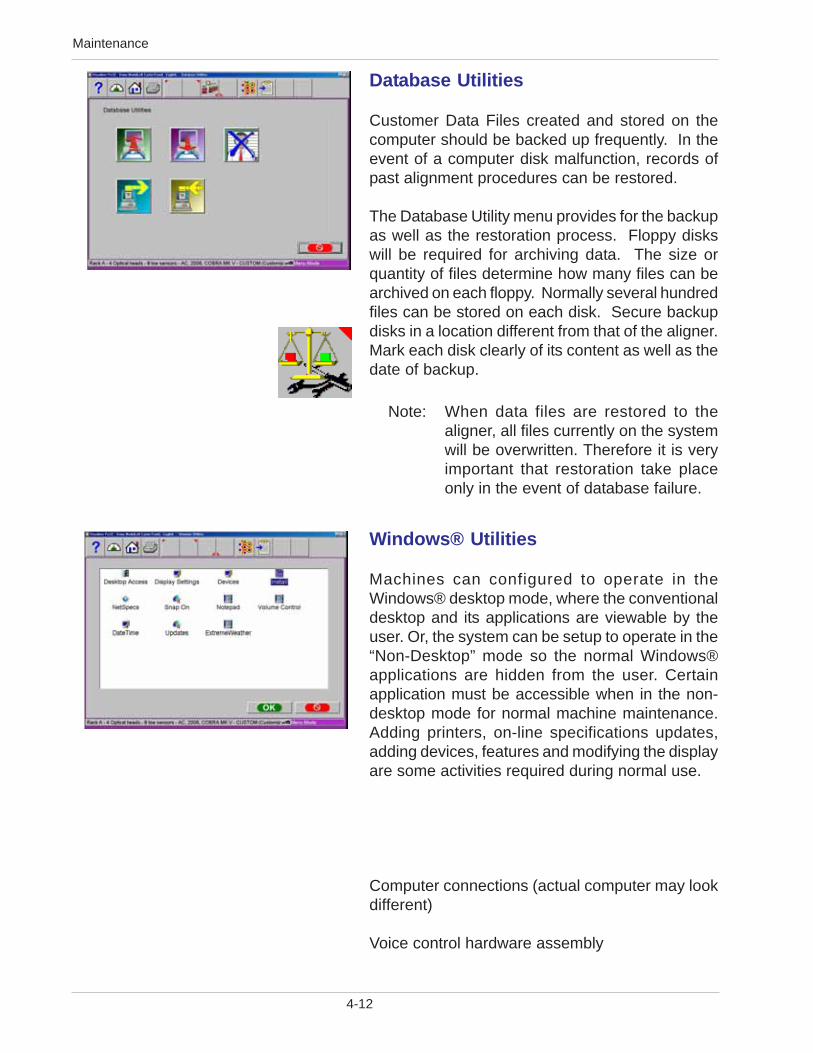
Maintenance
4-12
Database Utilities
Customer Data Files created and stored on thecomputer should be backed up frequently. In theevent of a computer disk malfunction, records ofpast alignment procedures can be restored.
The Database Utility menu provides for the backupas well as the restoration process. Floppy diskswill be required for archiving data. The size orquantity of files determine how many files can bearchived on each floppy. Normally several hundredfiles can be stored on each disk. Secure backupdisks in a location different from that of the aligner.Mark each disk clearly of its content as well as thedate of backup.
Note: When data files are restored to thealigner, all files currently on the systemwill be overwritten. Therefore it is veryimportant that restoration take placeonly in the event of database failure.
Windows® Utilities
Machines can configured to operate in theWindows® desktop mode, where the conventionaldesktop and its applications are viewable by theuser. Or, the system can be setup to operate in the“Non-Desktop” mode so the normal Windows®applications are hidden from the user. Certainapplication must be accessible when in the non-desktop mode for normal machine maintenance.Adding printers, on-line specifications updates,adding devices, features and modifying the displayare some activities required during normal use.
Computer connections (actual computer may lookdifferent)
Voice control hardware assembly

Maintenance
4-13
Monitor Keyboard USB Ports AC Power
Printer Mouse Network Sound
Computer connections - NOTE: Printer, Mouse and Keyboard are all USB devices, plug into any port
Voice control hardware assembly

Blank page

Form 5815-6 4.3...08/11/06...wdc...copyright 2001-2006 Snap-on Equipment Services Printed in the USA
Notice: The information contained in this document is subject to change without notice. EquipmentServices makes no warranty with regard to this material. shall not be liable for errors contained hereinor for incidental consequential damages in connection with furnishings, performance, or use of thismaterial.
This document contains proprietary information which is protected by copyright and patents. All rights arereserved. No part of this document may be photocopied, reproduced, or translated without prior writtenconsent of Equipment Services.
is a registered trademark of Equipment Services and Snap-on Equipment
USAEquipment Services309 Exchange AvenueConway, Arkansas 72032Tel.: (800) 362-8326 or (501) 450-1500Fax: (501) 450-1585
FRANCEJohn BeanSnap-On Equipment FranceZ.A. Du Vert Galant15, rue de la GuivernoneBP 717595310 Saint Ouen L’AumoneTel: (33) 1-3448-5878Fax: (33) 1-3448-5879
UNITED KINGDOMSnap-On Equipment Ltd.John Bean Equipment GroupOldmedow RoadKings LynnNorfolkPE30 4JW
CANADAJohn Bean6500 Millcreek DriveMississauga, OntarioCanada L5N 2W6Tel: (905) 814-0114Fax: (905) 814-0110
JBC GERMANYGeschaeftsbereich der Snap-on Equipment GmbHWerner-von-Siemens-Str. 2D-63419 PfungstadtDeutschlandTel: +49 (0) 6157 12 600Fax: +49 (0) 6157 12 601Website: www.johnbean.de
LATIN AMERICAInternational Equipment Group309 Exchange AvenueConway, Arkansas 72032Tel.: (501) 450-1568Fax: (501) 450-2086
®