CCC OWNERS MANUAL - EAB rev 5 - Bright Coop for a detailed preventative maintenance schedule. Inlet...
23
S S y y s s t t e e m m s s I I n n c c o o r r p p o o r r a a t t e e d d
Transcript of CCC OWNERS MANUAL - EAB rev 5 - Bright Coop for a detailed preventative maintenance schedule. Inlet...
SSyysstteemmss IInnccoorrppoorraatteedd

601 Buncombe Street, Greenville, SC 877-233-7104 Fax 864-233-7483 2
Table of Contents
Introduction
1. Safety 2. Machine Overview 3. Start-up Procedure 4. Warranty
Maintenance
1. Fan trailer and running gear 2. Generator Set 3. High Pressure Pump
Appendices I. Hatz Diesel Engine Instruction & Spare Parts books
II. Stamford AC Generator Manual III. CatPump® Operating and Maintenance manual IV. Trailer Documents V. Control Panel Schematic

601 Buncombe Street, Greenville, SC 877-233-7104 Fax 864-233-7483 3
Introduction Thank you for your purchase of the Cline Systems Inc. CCoooopp CCoooolleerr. This machine has been designed and fabricated to meet the growing need of live haul carriers to maintain a competitive advantage and high levels of animal welfare. By following the simple and basic information contained in this manual, the end user should see a long and safe operating life cycle for the equipment.
1. Safety
Read all instructions, warnings and cautions carefully. Follow all safety precautions to avoid personal injury or property damage during transportation, set-up and operation of the CCoooopp CCoooolleerr.. Cline Systems Inc. cannot be responsible for damage or injury resulting from unsafe product use, lack of maintenance, or incorrect product and unit operation. Contact Cline Systems Incorporated (1-877-233-7104) when in doubt as to the safety precautions and operation. Failure to comply with the following cautions and warnings could cause equipment damage and personal injury. - Is used to indicate correct operating or maintenance procedures and practices to prevent damage to, or destruction of equipment or other property.
CAUTION

601 Buncombe Street, Greenville, SC 877-233-7104 Fax 864-233-7483 4
- Indicates a potential danger that requires correct procedures or practices to avoid personal injury. - Is only used when your action or lack of action may cause serious injury or even death. Machine Overview Figures 1, 2 and 3 identify the major pieces of equipment that makeup the Coop Cooler.
Figure 1
WARNING
DANGER
Fan Bank
Hose reel
Generator Set with sub-base fuel tank
Rear Swing Panel
Forward Swing Panel

601 Buncombe Street, Greenville, SC 877-233-7104 Fax 864-233-7483 5
Figure 2
Cline Systems Inc., manufactures 2 versions of the Coop Cooler. The unit in figure 1 is an eight fan dual swing panel bumper pull model. The other is a nine fan gooseneck model with a forward fixed fan panel and a rear swing panel. Operation and major components are the same for either unit.
Pump Unit

601 Buncombe Street, Greenville, SC 877-233-7104 Fax 864-233-7483 6
Figure 3
The Coop Cooler Trailer is equipped with an electric braking system on both axles. The trailer tongue receiver requires the use of a 2-5/16” diameter hitch ball. WARNING – Never attempt to transport the unit without the proper size hitch ball and electrical connections to ensure proper operation of the trailers lighting and braking systems. Transport vehicle should be equipped with an electric brake controller.
Control Panel

601 Buncombe Street, Greenville, SC 877-233-7104 Fax 864-233-7483 7
WARNING - Never attempt to transport or reposition the Coop Cooler without first switching off all electrical power to the fans and pump unit, shutting down the generator, disconnecting the water supply, stow the water supply hose and folding and locking the swing panels. (See figures 4 & 5)
Figure 4
Coop Cooler properly secured for transport
Figure 5
Locking Clamp & Safety Pin
Locking Clamp
Safety Pin

601 Buncombe Street, Greenville, SC 877-233-7104 Fax 864-233-7483 8
WARNING – Never use the Coop Cooler to transport medium or heavy duty equipment, personnel or live stock. Start Up Procedure Maneuver the Coop Cooler next to the live haul vehicle. Maintain at least a 10’-0” clearance between the Coop Cooler and the live haul trailer. Release the locking clamp and safety pin (Figure 5, page 7), release the swing panel locking pins from their respective receivers (Figure 6) and swing open the forward and rear hinged fan panels (Figure 7).
Figure 6
Hinge panel locking pin
601 Buncombe Street, Greenville, SC 877-233-7104 Fax 864-233-7483 9
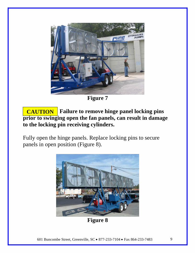
Figure 7
Failure to remove hinge panel locking pins prior to swinging open the fan panels, can result in damage to the locking pin receiving cylinders. Fully open the hinge panels. Replace locking pins to secure panels in open position (Figure 8).
Figure 8
CAUTION
601 Buncombe Street, Greenville, SC 877-233-7104 Fax 864-233-7483 10
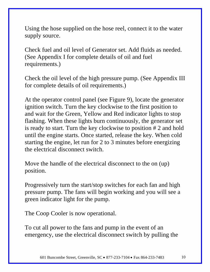
Using the hose supplied on the hose reel, connect it to the water supply source. Check fuel and oil level of Generator set. Add fluids as needed. (See Appendix I for complete details of oil and fuel requirements.) Check the oil level of the high pressure pump. (See Appendix III for complete details of oil requirements.) At the operator control panel (see Figure 9), locate the generator ignition switch. Turn the key clockwise to the first position to and wait for the Green, Yellow and Red indicator lights to stop flashing. When these lights burn continuously, the generator set is ready to start. Turn the key clockwise to position # 2 and hold until the engine starts. Once started, release the key. When cold starting the engine, let run for 2 to 3 minutes before energizing the electrical disconnect switch. Move the handle of the electrical disconnect to the on (up) position. Progressively turn the start/stop switches for each fan and high pressure pump. The fans will begin working and you will see a green indicator light for the pump. The Coop Cooler is now operational. To cut all power to the fans and pump in the event of an emergency, use the electrical disconnect switch by pulling the

601 Buncombe Street, Greenville, SC 877-233-7104 Fax 864-233-7483 11
level to the down (off ) position. Use this switch for emergency shut down only. To shut down the Coop Cooler, progressively turn the on/off switches to the left for each fan and high pressure pump. The fans and pump will turn off. Move the handle of the electrical disconnect to the off (down) position. Turn the key counter-clockwise to the 0 (zero) position on the generator ignition switch to shut down the generator. The Coop Cooler is now shut down and ready to begin stowage procedure for transport.
Figure 9 – Control Panel and Switches
Start/Stop Switches
Generator Ignition Switch
Generator Electrical
Power Disconnect
Switch (E-Stop)
601 Buncombe Street, Greenville, SC 877-233-7104 Fax 864-233-7483 12
Warranty The Coop Cooler is covered by a limited warranty against material and manufacturing defects for (1) one year from date of purchase. Failure to follow the operational and maintenance procedures as outlined by this owner’s manual and the vendor supplied equipment operation and service manuals will automatically void all warranties written or implied. Equipment abuse and misuse will also void Cline Systems Incorporated (1) year limited warranty. Warranty claims can be made in writing to Cline Systems Incorporated, 601 Buncombe Street Greenville, SC 29601 via e-mail at [email protected] or phone call to 877-233-7104.

601 Buncombe Street, Greenville, SC 877-233-7104 Fax 864-233-7483 13
Maintenance Fan trailer and running gear The Coop Cooler trailer requires very little in the way of maintenance. It is recommended that the wheel bearings and brakes be inspected for wear every 12 months if duty service is light or every 6 months for severe service. Tire pressure should be checked weekly and maintain cold inflation pressure per recommended pressure on trailer I.D. tag. Emergency break-away brake battery should be inspected and checked every 6 months. Trailer umbilical should be inspected for damage (frayed insulation, cracked plug) at every hook-up and disconnect from the tow vehicle. Any observed damage should be repaired immediately by a qualified electrician/mechanic prior to placing the Coop Cooler back into service. Trailer lights (turn signal, brake and running lights) should be inspected for proper operation every time the Coop Cooler is hooked to a tow vehicle for transport. Any lights not functioning properly should be repaired prior to using the Coop Cooler. Swing panel hinges should be greased every 6 months.

601 Buncombe Street, Greenville, SC 877-233-7104 Fax 864-233-7483 14
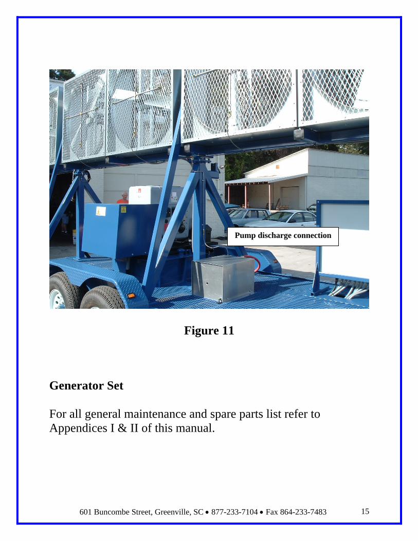
If the Coop Cooler is to be stored during the winter months, it is recommended that the water that may remain in the tubing and hoses of the high pressure water supply system be drained. This is accomplished by disconnecting the stainless steel braided hose end connected to the brass tee of the water supply header tubing (Figure 10). Also, disconnect the stainless steel braided hose from the discharge port of the high pressure pump (Figure 11). Once this remaining water has been drained, reconnect the hoses.
Figure 10
Hose to header connections
601 Buncombe Street, Greenville, SC 877-233-7104 Fax 864-233-7483 15
Figure 11
Generator Set For all general maintenance and spare parts list refer to Appendices I & II of this manual.
Pump discharge connection

601 Buncombe Street, Greenville, SC 877-233-7104 Fax 864-233-7483 16
High Pressure Pump
The Coop Cooler is supplied with a Catpump® SP plunger pump, Model number 2SF22ELS. Cline Systems Incorporated highly recommends that you strictly adhere to all maintenance and service schedules as outlined in the SF plunger pump service manual found in Appendix III of this manual. Failure to do so will void the pump factory warranty and Cline Systems Incorporated limited 1 year warranty. The following check and maintenance instructions are for your quick reference prior to starting the high pressure pump. These instructions are supplemental and in no way written or implied, override the Catpump® SP plunger pump service manual. The High Pressure pump supplied with the Coop Cooler is extremely easy to operate and maintain as long as some very simple but important steps are followed prior to starting up the unit
1. Pump Oil level check 2. Inlet water pressure check 3. Water and Oil leaks check
Oil Level
Pump oil level should be checked before each use. The pump oil level is checked via the sight glass that is located on the front of the pump. The proper oil level can only be determined with the pump not running. Oil level should
601 Buncombe Street, Greenville, SC 877-233-7104 Fax 864-233-7483 17
read mid level of the sight glass. Avoid over filling pump when adding oil to recommended level.
The pump manufacturer CatPumps® recommends that the pump lubrication oil be change after every 500 hours of operation using multi-viscosity ISO68 oil. Each pump requires a 50 hour break in period after which the lubrication oil needs to be changed. After the break in period, oil change intervals follow manufactures recommendation. Cline Systems Incorporated suggests purchasing pump lubrication oil per CatPumps® recommendation and specification or through Cline Systems Incorporated. Refer to the Catpump® SP plunger pump service manual in Appendix III of this manual for a detailed preventative maintenance schedule.
Inlet Water Pressure
The high pressure pump requires a minimum of 10 p.s.i. of inlet water pressure to be able to start the pump. Always insure that the inlet water is on before starting the system. A pressure switch located between the pump and inlet water connection monitors this. If this switch fails, pump operation stops. Repair or replacement of this switch will be required in order to bring the pump back in operation. NEVER UNDER ANY CIRCUMSTANCE RUN THE PUMP UNIT WITHOUT WATER. DOING SO WILL RESULT IN SERIOUS MECHANICAL DAMAGE.

601 Buncombe Street, Greenville, SC 877-233-7104 Fax 864-233-7483 18
Oil and Water Leaks The pump and its water distribution system should be checked daily for any signs of oil and water leaks. Any leaks detected should be repaired immediately to avoid degradation of performance and damage to the pump. Consult the Catpump® SP plunger pump service manual located in Appendix III of this manual for detail maintenance and repair information.
Pump Discharge Pressure
The High pressure pump unit is factory set to operate at 1,000 p.s.i. This enables the pump to operate properly and extend pump life. The pump unit is provided with a 1,500 p.s.i. liquid filled gauge located on the front cover panel of the pump unit to monitor system pressure. If at any time the system pressure exceeds or falls below the 1000 p.s.i. setting, it is highly recommended that the pump be shut down and the cause of the problem corrected, before continued operation. Contact Cline Systems Incorporated at 877-233-7104 is you need assistance.
Inlet Water Filter
The pump water inlet connection is fitted with a 5-micron filter that filters the inlet water. Water filters should be changed at every 500 hours of operation or with every oil change of the pump. Depending on water purity, this filter may need to be changed at a much earlier interval.

601 Buncombe Street, Greenville, SC 877-233-7104 Fax 864-233-7483 19
Appendix I
Hatz Diesel Engine Instruction & Spare Parts Books

601 Buncombe Street, Greenville, SC 877-233-7104 Fax 864-233-7483 20
Appendix II
Marelli AC Generator Manual

601 Buncombe Street, Greenville, SC 877-233-7104 Fax 864-233-7483 21
Appendix III
CatPump® Operating and Maintenance Manual

601 Buncombe Street, Greenville, SC 877-233-7104 Fax 864-233-7483 22
Appendix IV
Trailer Documents

601 Buncombe Street, Greenville, SC 877-233-7104 Fax 864-233-7483 23
Appendix V
Control Panel Schematic Drawings