CC3200 SimpleLink Wi-Fi and IoT Solution with MCU LaunchPad ...
29
CC3200 SimpleLink™ Wi-Fi ® and IoT Solution with MCU LaunchPad Hardware User's Guide Literature Number: SWRU372B June 2014–Revised January 2015
-
Upload
phungthien -
Category
Documents
-
view
239 -
download
2
Transcript of CC3200 SimpleLink Wi-Fi and IoT Solution with MCU LaunchPad ...

CC3200 SimpleLink™ Wi-Fi® and IoT Solutionwith MCU LaunchPad Hardware
User's Guide
Literature Number: SWRU372BJune 2014–Revised January 2015
Contents
1 Introduction......................................................................................................................... 41.1 CC3200 LaunchPad ..................................................................................................... 41.2 Key Features ............................................................................................................. 41.3 What's Included .......................................................................................................... 51.4 FCC/IC Regulatory Compliance........................................................................................ 5
2 Hardware Description ........................................................................................................... 52.1 Block Diagram ........................................................................................................... 62.2 Hardware Features....................................................................................................... 62.3 Connecting a BoosterPack.............................................................................................. 72.4 Jumpers, switches and LEDs........................................................................................... 72.5 Power..................................................................................................................... 152.6 Measure CC3200 Current Draw ...................................................................................... 172.7 RF Connections......................................................................................................... 202.8 Design Files ............................................................................................................. 21
3 Software Examples ............................................................................................................. 223.1 Development Environment Requirements........................................................................... 22
4 Additional Resources.......................................................................................................... 224.1 LaunchPad Wiki......................................................................................................... 224.2 Information on the CC3200............................................................................................ 224.3 Download CCS, IAR.................................................................................................... 224.4 The CC3200 Code Examples ......................................................................................... 224.5 CC3200 Application Notes ............................................................................................ 224.6 The Community ......................................................................................................... 23
5 Known Limitations.............................................................................................................. 235.1 Hardware Limitations................................................................................................... 23
Revision History.......................................................................................................................... 24Revision History.......................................................................................................................... 24
2 Table of Contents SWRU372B–June 2014–Revised January 2015Submit Documentation Feedback
Copyright © 2014–2015, Texas Instruments Incorporated

www.ti.com
List of Figures1 CC3200 LaunchPad EVM Overview ...................................................................................... 52 CC3200 Block Diagram ..................................................................................................... 63 Pn-1 Marking on the LaunchPad (white triangle)........................................................................ 74 JTAG Headers ............................................................................................................... 75 I2C Connections ............................................................................................................. 86 UART Signals............................................................................................................... 107 SOP Jumpers ............................................................................................................... 118 2x20 Pin Connector ....................................................................................................... 159 Powering From USB ....................................................................................................... 1610 Battery Power............................................................................................................... 1711 Measuring Low Power ..................................................................................................... 1812 Measuring Active Power................................................................................................... 1913 Radiated Testing Using Chip Antenna .................................................................................. 2014 Board Set for Conducted Testing ........................................................................................ 20
List of Tables1 JTAG Headers ............................................................................................................... 82 Jumper Settings.............................................................................................................. 83 Default I2C Addresses ...................................................................................................... 94 Jumper Settings.............................................................................................................. 95 UART Signals............................................................................................................... 106 SOP Lines ................................................................................................................... 117 Miscellaneous Settings .................................................................................................... 128 Push Buttons................................................................................................................ 139 LEDs ......................................................................................................................... 1410 Change Log ................................................................................................................. 21
3SWRU372B–June 2014–Revised January 2015 List of FiguresSubmit Documentation Feedback
Copyright © 2014–2015, Texas Instruments Incorporated

User's GuideSWRU372B–June 2014–Revised January 2015
CC3200 SimpleLink™ Wi-Fi® and IoT Solution with MCULaunchPad Hardware
1 Introduction
1.1 CC3200 LaunchPadThe high performance CC3200 is the industry's first single-chip Microcontroller (MCU) with built-in Wi-Ficonnectivity for the LaunchPad™ ecosystem. Created for the Internet of Things (IoT), the SimpleLink Wi-Fi CC3200 device is a wireless MCU that integrates a high-performance ARM® Cortex®-M4 MCU allowingcustomers to develop an entire application with a single IC. With on-chip Wi-Fi, internet and robustsecurity protocols, no prior Wi-Fi experience is needed for faster development.
The CC3200 LaunchPad is a low-cost evaluation platform for ARM® Cortex™-M4F-basedmicrocontrollers. The LaunchPad design highlights the CC3200 Internet-on-a-chip™ solution and WiFicapabilities. The CC3200 LaunchPad also features programmable user buttons, RGB LED for customapplications and onboard emulation for debugging. The stackable headers of the CC3200 LaunchPad XLinterface demonstrate how easy it is to expand the functionality of the LaunchPad when interfacing withother peripherals on many existing BoosterPack add-on boards such as graphical displays, audio codec,antenna selection, environmental sensing, and much more. Figure 1 shows a photo of the CC3200LaunchPad.
Free software development tools are also available, including TI’s Eclipse-based Code ComposerStudio™ and IAR Embedded Workbench®. More information about the LaunchPad, the supportedBoosterPacks, and the available resources can be found at TI’s LaunchPad portal. Also visit the CC3200Wiki page for design resources and example projects.
NOTE: The antennas used for this transmitter must be installed to provide a separation distance ofat least 20 cm from all persons and must not be co-located or operating in conjunction withany other antenna or transmitter.
NOTE: All figures and references in this document apply to the Rev3.2. Most of the document alsoapplies to the Rev4.1, unless otherwise stated. For the exact list of changes made acrossboard revisions, refer to Section 2.8.2.
1.2 Key Features• CC3200, SimpleLink Wi-Fi, internet-on-a-chip™ solution with integrated MCU• 40-pin LaunchPad standard that leverages the BoosterPack ecosystem• FTDI based JTAG emulation with serial port for Flash programming• Two buttons and three LEDs for user interaction• Backchannel universal asynchronous receiver/transmitter (UART) through USB to PC• On-board chip antenna with U.FL for conducted testing
SimpleLink, LaunchPad, Code Composer Studio are trademarks of Texas Instruments.ARM® Cortex is a trademark of ARM Limited.ARM, Cortex are registered trademarks of ARM Limited.IAR Embedded Workbench is a registered trademark of IAR Systems AB.Wi-Fi is a registered trademark of Wi-Fi Alliance.All other trademarks are the property of their respective owners.
4 CC3200 SimpleLink™ Wi-Fi® and IoT Solution with MCU LaunchPad SWRU372B–June 2014–Revised January 2015Hardware Submit Documentation Feedback
Copyright © 2014–2015, Texas Instruments Incorporated

www.ti.com Introduction
• On-board accelerometer and temperature sensor for out-of-box demo• Micro USB connector for power and debug connections
1.3 What's Included
Kit Contents• CC3200 LaunchPad development tool• Micro USB cable• Quick start guide
1.4 FCC/IC Regulatory ComplianceThe CC3200 SimpleLink Wi-Fi and IoT solution with MCU LaunchPad hardware is FCC Part 15 and ICICES-003 Class A compliant.
2 Hardware Description
Figure 1. CC3200 LaunchPad EVM Overview
5SWRU372B–June 2014–Revised January 2015 CC3200 SimpleLink™ Wi-Fi® and IoT Solution with MCU LaunchPadHardwareSubmit Documentation Feedback
Copyright © 2014–2015, Texas Instruments Incorporated
Hardware Description www.ti.com
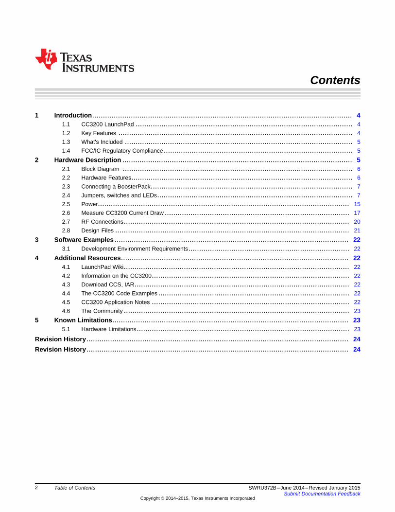
2.1 Block Diagram
Figure 2. CC3200 Block Diagram
2.2 Hardware Features• CC3200, SimpleLink Wi-Fi, internet-on-a-chip solution with integrated MCU40-pin LaunchPad standard
that leverages the BoosterPack ecosystem• FTDI-based JTAG emulation with serial port for Flash programming• Supports both 4-wire JTAG and 2-wire SWD• Two buttons and three LEDs for user interaction• Virtual COM port UART through USB on PC• On-board chip antenna with U.FL for conducted testing• On-board accelerometer and temperature sensor for out-of-box demo with option to isolate them from
the inter-integrated circuit (I2C) bus• Micro USB connector for power and debug connections• Headers for current measurement and external JTAG connection• Bus-powered device with no external power required for Wi-Fi• Long range transmission with highly optimized antenna (200m typical in open air with a 6dBi antenna
AP)• Can be powered externally, with 2xAA or 2xAAA alkaline batteries working down to 2.3V typical (typ)
6 CC3200 SimpleLink™ Wi-Fi® and IoT Solution with MCU LaunchPad SWRU372B–June 2014–Revised January 2015Hardware Submit Documentation Feedback
Copyright © 2014–2015, Texas Instruments Incorporated
www.ti.com Hardware Description
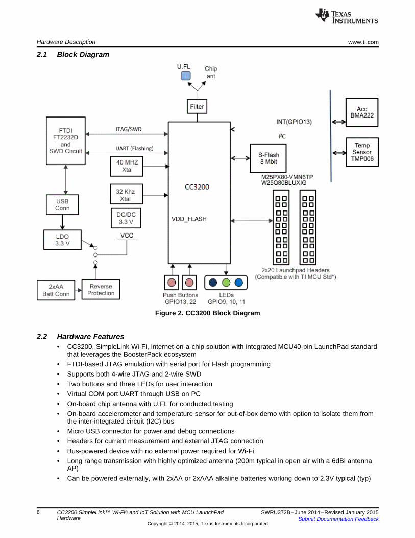
2.3 Connecting a BoosterPackA compatible BoosterPack can be stacked on top of the LaunchPad using the 2x20 pin connectors. Notethat the connectors do not have a “key” to prevent the misalignment of the pins or reverse connection.Ensure that Vcc and 5V pins, are aligned with the BoosterPack header pins. On the CC3200 LaunchPad,a small white triangle symbol is provided near Pin-1 (see Figure 3) to orient all BoosterPacks. This samemarking, provided on compatible BoosterPacks, needs to be aligned before powering up the boards.
Figure 3. Pn-1 Marking on the LaunchPad (white triangle)
2.4 Jumpers, switches and LEDs
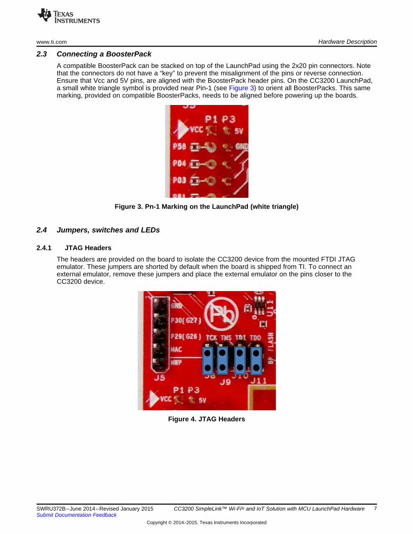
2.4.1 JTAG HeadersThe headers are provided on the board to isolate the CC3200 device from the mounted FTDI JTAGemulator. These jumpers are shorted by default when the board is shipped from TI. To connect anexternal emulator, remove these jumpers and place the external emulator on the pins closer to theCC3200 device.
Figure 4. JTAG Headers
7SWRU372B–June 2014–Revised January 2015 CC3200 SimpleLink™ Wi-Fi® and IoT Solution with MCU LaunchPad HardwareSubmit Documentation Feedback
Copyright © 2014–2015, Texas Instruments Incorporated

Hardware Description www.ti.com
Table 1. JTAG Headers
Reference Usage CommentsJ8 (TCK) (1) JTAG Short : Routes the on-board emulator to the CC3200J9 (TMS) (1)
J10 (TDI) Open: Isolate the on-board emulator from the CC3200.J11(TDO)
(1) For the SWD mode, only TCK and TMS need to be shorted to the CC3200.
When a battery is used, be sure to disconnect all the JTAG headers to prevent any reverse leakagecurrent.
2.4.2 I2C ConnectionsThe board features an accelerometer and a temperature sensor for the out-of-box demo. These areconnected to the I2C bus and can be isolated using the jumpers provided.
Figure 5. I2C Connections
By removing J2 and J3, the accelerometer and the temperature sensors are isolated from the I2C bus.Note that this also removes any pull-up resistor from the I2C bus.
2.4.2.1 Jumper Settings
Table 2. Jumper Settings
Reference Usage CommentsJ2 I2C SDA Short : Connect the CC3200 I2C bus to the on-board sensors with pull-up
Open : Isolate the sensors from the CC3200J3 I2C SCL Short : Connect the CC3200 I2C bus to the on-board sensors with pull-up
Open : Isolate the sensors from the CC320J4 INT Short : Connect the accelerometer interrupt to the CC3200 on GPIO13
8 CC3200 SimpleLink™ Wi-Fi® and IoT Solution with MCU LaunchPad SWRU372B–June 2014–Revised January 2015Hardware Submit Documentation Feedback
Copyright © 2014–2015, Texas Instruments Incorporated
www.ti.com Hardware Description
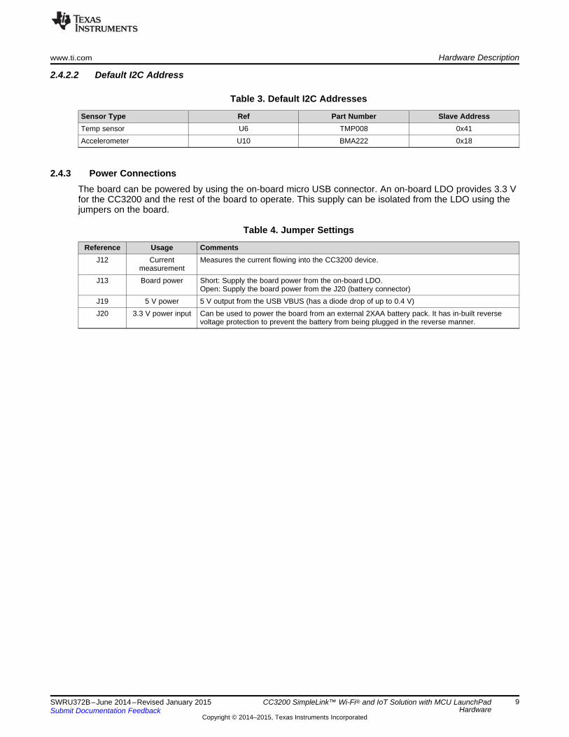
2.4.2.2 Default I2C Address
Table 3. Default I2C Addresses
Sensor Type Ref Part Number Slave AddressTemp sensor U6 TMP008 0x41Accelerometer U10 BMA222 0x18
2.4.3 Power ConnectionsThe board can be powered by using the on-board micro USB connector. An on-board LDO provides 3.3 Vfor the CC3200 and the rest of the board to operate. This supply can be isolated from the LDO using thejumpers on the board.
Table 4. Jumper Settings
Reference Usage CommentsJ12 Current Measures the current flowing into the CC3200 device.
measurementJ13 Board power Short: Supply the board power from the on-board LDO.
Open: Supply the board power from the J20 (battery connector)J19 5 V power 5 V output from the USB VBUS (has a diode drop of up to 0.4 V)J20 3.3 V power input Can be used to power the board from an external 2XAA battery pack. It has in-built reverse
voltage protection to prevent the battery from being plugged in the reverse manner.
9SWRU372B–June 2014–Revised January 2015 CC3200 SimpleLink™ Wi-Fi® and IoT Solution with MCU LaunchPadHardwareSubmit Documentation Feedback
Copyright © 2014–2015, Texas Instruments Incorporated

UART for Flashing Mode UART for BoosterPack
Hardware Description www.ti.com
2.4.4 UART SignalsThe board supports a USB-based virtual COM port, which is used on the FTDI device FT2232D. Thereare two ports on the FT2232: the first port is dedicated for the emulation (JTAG/SWD) and the second portis used for the virtual COM port. The UART can also be routed to the 20-pin connector and the selectionis performed using jumpers on the board.
Figure 6. UART Signals
Table 5. UART Signals
Reference Usage CommentsJ6, J7 UART for Flash Short 1-2: Route the signals to the 20 pin connector.
programming Short 2-3: Route the signals to the FTDI for Flash programming.
10 CC3200 SimpleLink™ Wi-Fi® and IoT Solution with MCU LaunchPad SWRU372B–June 2014–Revised January 2015Hardware Submit Documentation Feedback
Copyright © 2014–2015, Texas Instruments Incorporated

www.ti.com Hardware Description
2.4.5 Sense on PowerThe CC3200 can be set to operate in three different modes based on the state of the Sense on Power(SOP) lines. These are pins 21, 34, 35 on the CC3200 device. The state of the device is described inTable 6.
Table 6. SOP Lines
Usage CommentsSOP[2:0] 100 = Flash programming
000 = Functional mode + 4 Wire JTAG001 = Functional mode + 2 Wire JTAG
Note: SOP[2:0] corresponds to J15, J16, and J17, in the LaunchPad schematic design.
Figure 7. SOP Jumpers
11SWRU372B–June 2014–Revised January 2015 CC3200 SimpleLink™ Wi-Fi® and IoT Solution with MCU LaunchPadHardwareSubmit Documentation Feedback
Copyright © 2014–2015, Texas Instruments Incorporated

Hardware Description www.ti.com
2.4.6 Other Miscellaneous
Table 7. Miscellaneous Settings
Reference Usage CommentsJ4 Accelerometer Short = Route the Accelerometer sensor interrupt to the GPIO_13
Interrupt Open = Isolates the Interrupt to the GPIO_13
J5 Debug Header To observe the Network Processor (NWP), MAC Logs.
J14 SOP2 Isolation Isolate SOP2 (GPIO_25) from the 20 pin connector
12 CC3200 SimpleLink™ Wi-Fi® and IoT Solution with MCU LaunchPad SWRU372B–June 2014–Revised January 2015Hardware Submit Documentation Feedback
Copyright © 2014–2015, Texas Instruments Incorporated
www.ti.com Hardware Description
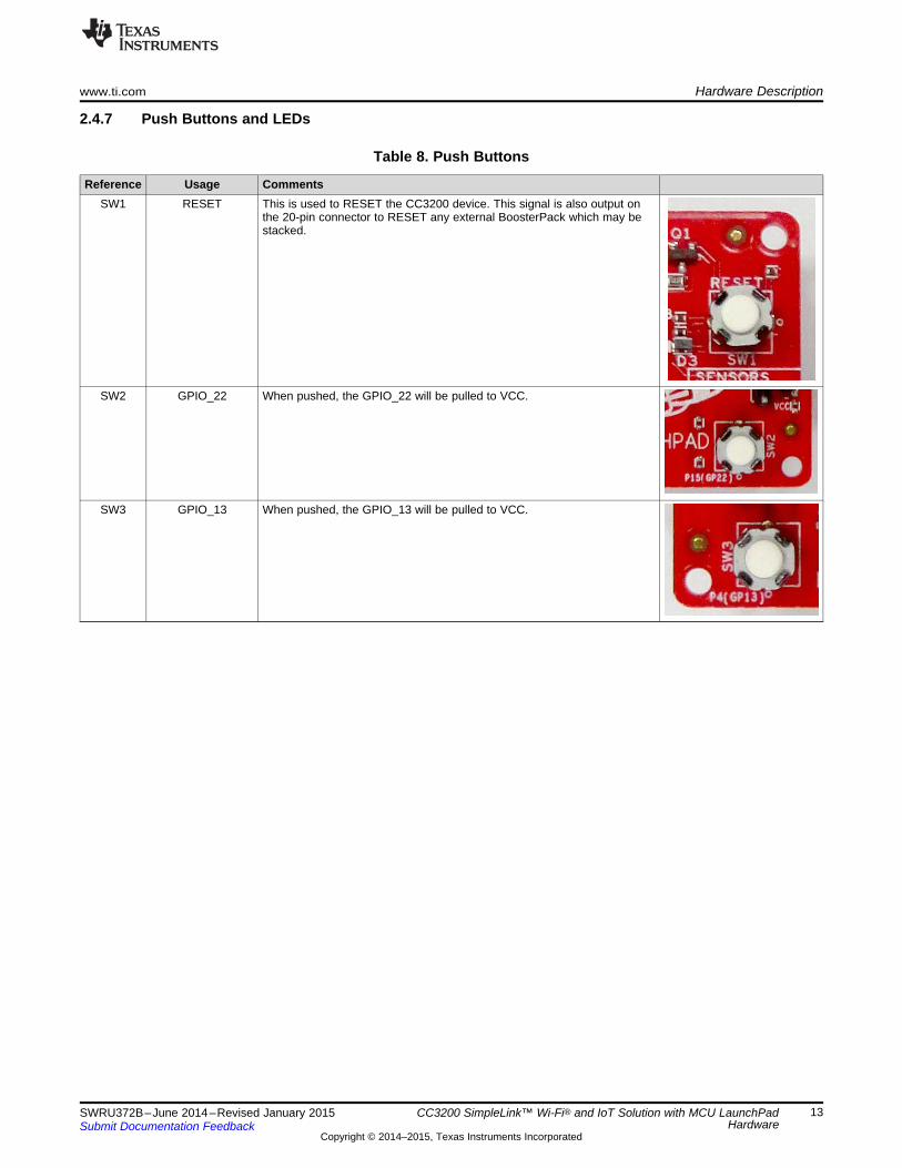
2.4.7 Push Buttons and LEDs
Table 8. Push Buttons
Reference Usage CommentsSW1 RESET This is used to RESET the CC3200 device. This signal is also output on
the 20-pin connector to RESET any external BoosterPack which may bestacked.
SW2 GPIO_22 When pushed, the GPIO_22 will be pulled to VCC.
SW3 GPIO_13 When pushed, the GPIO_13 will be pulled to VCC.
13SWRU372B–June 2014–Revised January 2015 CC3200 SimpleLink™ Wi-Fi® and IoT Solution with MCU LaunchPadHardwareSubmit Documentation Feedback
Copyright © 2014–2015, Texas Instruments Incorporated

Hardware Description www.ti.com
Table 9. LEDs
Reference Colo4 Usage CommentsD1 Yellow nRESET This LED is used to indicate the state of nRESET pin. If this LED is
glowing, the device is functional.
D2 Green Debug This LED glows whenever the debugging it enabled over the JTAG
D4 RED Power Indicates when the 3.3 V power is supplied to the board.
D5 GREEN GPIO_11 (1) Glows when the GPIO is logic-1D6 YELLOW GPIO_10 (1) Glows when the GPIO is logic-1D7 RED GPIO_09 Glows when the GPIO is logic-1
(1) GPIO_10 and GPIO_11 are used as I2C also. So whenever the pull-ups are enabled, the LEDs would glow.
14 CC3200 SimpleLink™ Wi-Fi® and IoT Solution with MCU LaunchPad SWRU372B–June 2014–Revised January 2015Hardware Submit Documentation Feedback
Copyright © 2014–2015, Texas Instruments Incorporated

CC3200
P1 P3
Ref Signal
Dev
Pin#
Dev
Pin# Signal
1 3.3V 5V
2 ADC_CH1 58 GND
3 UART0_RX 4 57 ADC_CH0
4 UART0_TX 3 60 ADC_CH3
5 GPIO 61 58* ADC_CH1
6 ADC_CH2 59 59* ADC_CH2
7 SPI_CLK 5 63 AUD_SYNC
8 GPIO 62 53 AUD_CLK
9 I2C_SCL 1 64 AUD_DOUT
10 I2C_SDA 2 50 AUD_DIN
P4 P2
Signal
Dev
Pin#
Dev
Pin# Signal Ref
PWM 2* GND 1
PWM 1* 18 GPIO 2
PWM 17* 8 SPI_CS 3
PWM 64* 45 GPIO 4
CCAP/GPIO 21* RESET_OUT 5
CCAP/GPIO 18* 7 SPI_DOUT 6
GPIO 62* 6 SPI_DIN 7
GPIO 60* 21 GPIO 8
GPIO 16 55 GPIO 9
GPIO 17 15 GPIO 10
www.ti.com Hardware Description
2.4.8 2x20 Pin Connector AssignmentThe signal assignment on the 2x20 pin connector is shown in Figure 8. The P1-Pn naming convention isused for 2x20 pin connectors only.
Figure 8. 2x20 Pin Connector
The signal mappings are as indicated in above table shown in Figure 8. All the signals are referred by thepin number in the SDK and Figure 8 shows the default mappings. Note that some of the pins are repeatedacross the connector. For instance, pin 62 is available on P1 and P4, but only P1 is connected by default.The signal on P4 is marked with a *(star) to signify that it is not connected by default. It can be routed tothe pin by using a 0 Ω resistor in the path. For the exact resistor placement, see the schematics andplacement diagram.
2.5 PowerThe LaunchPad is designed such that it can be powered by the USB connection or by external2xAA/2xAAA batteries.
15SWRU372B–June 2014–Revised January 2015 CC3200 SimpleLink™ Wi-Fi® and IoT Solution with MCU LaunchPadHardwareSubmit Documentation Feedback
Copyright © 2014–2015, Texas Instruments Incorporated
Hardware Description www.ti.com
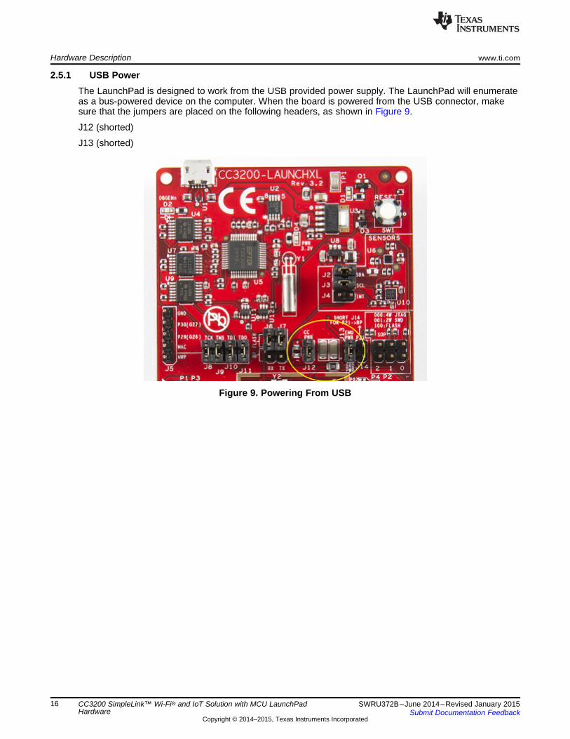
2.5.1 USB PowerThe LaunchPad is designed to work from the USB provided power supply. The LaunchPad will enumerateas a bus-powered device on the computer. When the board is powered from the USB connector, makesure that the jumpers are placed on the following headers, as shown in Figure 9.
J12 (shorted)
J13 (shorted)
Figure 9. Powering From USB
16 CC3200 SimpleLink™ Wi-Fi® and IoT Solution with MCU LaunchPad SWRU372B–June 2014–Revised January 2015Hardware Submit Documentation Feedback
Copyright © 2014–2015, Texas Instruments Incorporated
www.ti.com Hardware Description
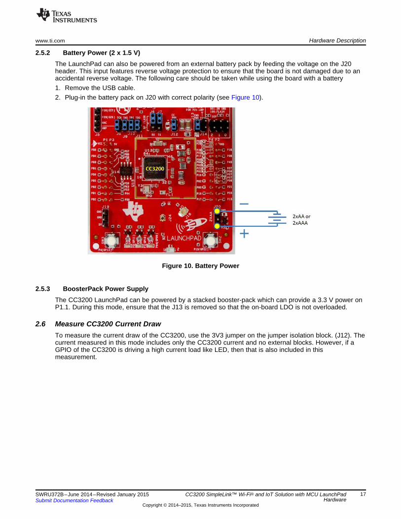
2.5.2 Battery Power (2 x 1.5 V)The LaunchPad can also be powered from an external battery pack by feeding the voltage on the J20header. This input features reverse voltage protection to ensure that the board is not damaged due to anaccidental reverse voltage. The following care should be taken while using the board with a battery1. Remove the USB cable.2. Plug-in the battery pack on J20 with correct polarity (see Figure 10).
Figure 10. Battery Power
2.5.3 BoosterPack Power SupplyThe CC3200 LaunchPad can be powered by a stacked booster-pack which can provide a 3.3 V power onP1.1. During this mode, ensure that the J13 is removed so that the on-board LDO is not overloaded.
2.6 Measure CC3200 Current DrawTo measure the current draw of the CC3200, use the 3V3 jumper on the jumper isolation block. (J12). Thecurrent measured in this mode includes only the CC3200 current and no external blocks. However, if aGPIO of the CC3200 is driving a high current load like LED, then that is also included in thismeasurement.
17SWRU372B–June 2014–Revised January 2015 CC3200 SimpleLink™ Wi-Fi® and IoT Solution with MCU LaunchPadHardwareSubmit Documentation Feedback
Copyright © 2014–2015, Texas Instruments Incorporated
Hardware Description www.ti.com
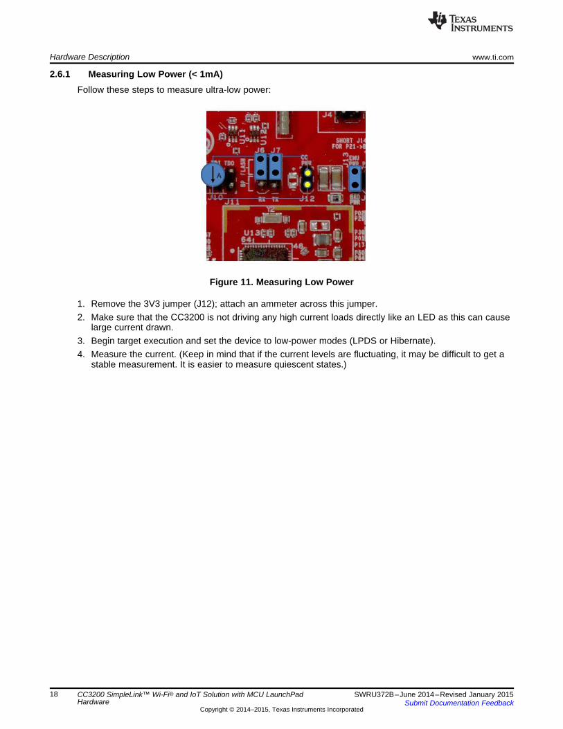
2.6.1 Measuring Low Power (< 1mA)Follow these steps to measure ultra-low power:
Figure 11. Measuring Low Power
1. Remove the 3V3 jumper (J12); attach an ammeter across this jumper.2. Make sure that the CC3200 is not driving any high current loads directly like an LED as this can cause
large current drawn.3. Begin target execution and set the device to low-power modes (LPDS or Hibernate).4. Measure the current. (Keep in mind that if the current levels are fluctuating, it may be difficult to get a
stable measurement. It is easier to measure quiescent states.)
18 CC3200 SimpleLink™ Wi-Fi® and IoT Solution with MCU LaunchPad SWRU372B–June 2014–Revised January 2015Hardware Submit Documentation Feedback
Copyright © 2014–2015, Texas Instruments Incorporated
www.ti.com Hardware Description
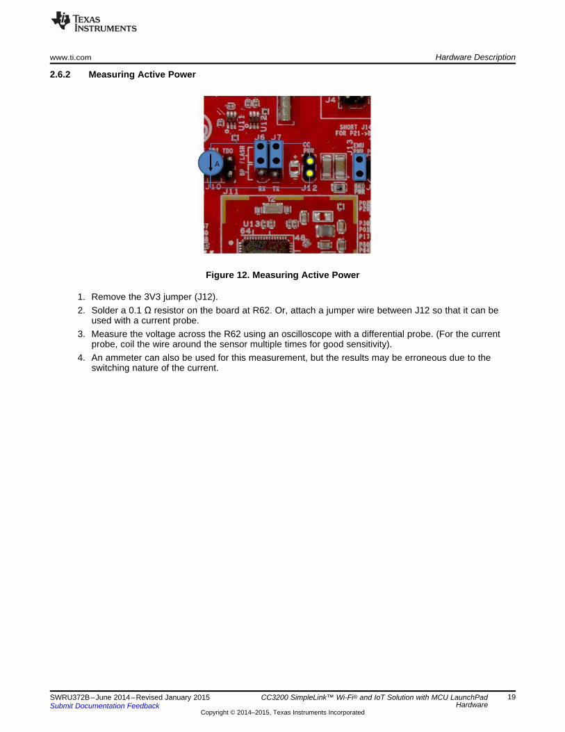
2.6.2 Measuring Active Power
Figure 12. Measuring Active Power
1. Remove the 3V3 jumper (J12).2. Solder a 0.1 Ω resistor on the board at R62. Or, attach a jumper wire between J12 so that it can be
used with a current probe.3. Measure the voltage across the R62 using an oscilloscope with a differential probe. (For the current
probe, coil the wire around the sensor multiple times for good sensitivity).4. An ammeter can also be used for this measurement, but the results may be erroneous due to the
switching nature of the current.
19SWRU372B–June 2014–Revised January 2015 CC3200 SimpleLink™ Wi-Fi® and IoT Solution with MCU LaunchPadHardwareSubmit Documentation Feedback
Copyright © 2014–2015, Texas Instruments Incorporated
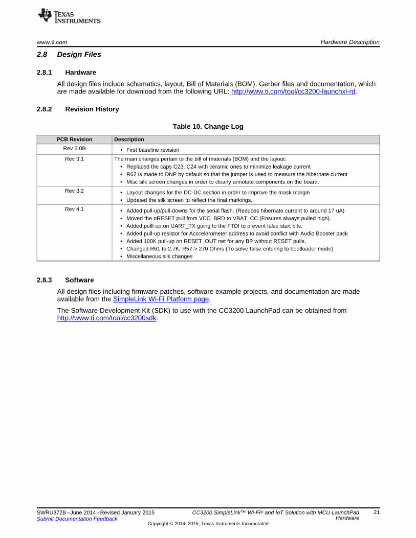
Resistor mounted
towards U.FL
Murata connector
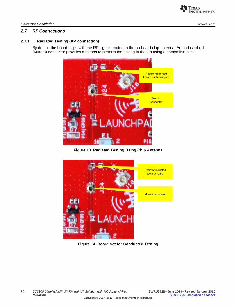
Resistor mounted
towards antenna path
Murata
Connector
Hardware Description www.ti.com
2.7 RF Connections
2.7.1 Radiated Testing (AP connection)By default the board ships with the RF signals routed to the on-board chip antenna. An on-board u.fl(Murata) connector provides a means to perform the testing in the lab using a compatible cable.
Figure 13. Radiated Testing Using Chip Antenna
Figure 14. Board Set for Conducted Testing
20 CC3200 SimpleLink™ Wi-Fi® and IoT Solution with MCU LaunchPad SWRU372B–June 2014–Revised January 2015Hardware Submit Documentation Feedback
Copyright © 2014–2015, Texas Instruments Incorporated
www.ti.com Hardware Description
2.8 Design Files
2.8.1 HardwareAll design files include schematics, layout, Bill of Materials (BOM), Gerber files and documentation, whichare made available for download from the following URL: http://www.ti.com/tool/cc3200-launchxl-rd.
2.8.2 Revision History
Table 10. Change Log
PCB Revision DescriptionRev 3.0B • First baseline revisionRev 3.1 The main changes pertain to the bill of materials (BOM) and the layout:
• Replaced the caps C23, C24 with ceramic ones to minimize leakage current• R62 is made to DNP by default so that the jumper is used to measure the hibernate current• Misc silk screen changes in order to clearly annotate components on the board.
Rev 3.2 • Layout changes for the DC-DC section in order to improve the mask margin• Updated the silk screen to reflect the final markings.
Rev 4.1 • Added pull-up/pull-downs for the serial flash. (Reduces hibernate current to around 17 uA)• Moved the nRESET pull from VCC_BRD to VBAT_CC (Ensures always pulled high).• Added pulll-up on UART_TX going to the FTDI to prevent false start bits.• Added pull-up resistor for Acccelerometer address to avoid conflict with Audio Booster pack• Added 100K pull-up on RESET_OUT net for any BP without RESET pulls.• Changed R61 to 2.7K, R57-> 270 Ohms (To solve false entering to bootloader mode)• Miscellaneous silk changes
2.8.3 SoftwareAll design files including firmware patches, software example projects, and documentation are madeavailable from the SimpleLink Wi-Fi Platform page.
The Software Development Kit (SDK) to use with the CC3200 LaunchPad can be obtained fromhttp://www.ti.com/tool/cc3200sdk.
21SWRU372B–June 2014–Revised January 2015 CC3200 SimpleLink™ Wi-Fi® and IoT Solution with MCU LaunchPadHardwareSubmit Documentation Feedback
Copyright © 2014–2015, Texas Instruments Incorporated

Software Examples www.ti.com
3 Software Examples
3.1 Development Environment RequirementsTo use any of the following software examples with the LaunchPad, you must have an integrateddevelopment environment (IDE) that supports the CC3200 device.
For more details on where to download the latest IDE, see Section 4.3.
The CC3200 Programmer's guide (SWRU369) has detailed information on software environment setup,and examples. Please refer to this document for further details on the software sample examples.
3.1.1 CCSCCS 6.0 or higher is required. When CCS has been launched, and a workspace directory chosen, useProject → Import Existing CCS Eclipse Project. Direct it to the desired demo’s project directory containingmain.c.
3.1.2 IARIAR 6.70 or higher is required. To open the demo in IAR, simply choose File → Open → Workspace…,and direct it to the *.eww workspace file inside the \IAR subdirectory of the desired demo. All workspaceinformation is contained within this file.
The subdirectory also has an *.ewp project file; this file can be opened into an existing workspace, usingProject → Add-Existing-Project….
4 Additional Resources
4.1 LaunchPad WikiMost updated information would be available on the CC3200 Wiki page.
4.2 Information on the CC3200For more information on CC3200 visit the product page (http://www.ti.com/product/cc3200) (datasheet andkey documents like the technical reference manual (TRM)) and Wiki (http://www.ti.com/simplelinkwifi-wiki)(Organize information for Getting started, Hardware details, Software details including porting information,Test/Certification and Support and Community).
4.3 Download CCS, IARAlthough the files can be viewed with any text editor, more can be done with the projects if they’re openedwith a development environment like Code Composer Studio (CCS), IAR, or Energia.
CCS and IAR are each available in a full version, or a free, code-size-limited version. The full out-of-boxdemo cannot be built with the free version of CCS or IAR (IAR Kickstart) due to the code size limit. Tobypass this limitation, a code-size-limited CCS version is provided, that has most functionality integratedinto a library. The code that is built into the library is able to be viewed by the user, but it cannot be edited.For full functionality download the full version of either CCS or IAR.
4.4 The CC3200 Code ExamplesThe user's guide for each example can be found within the Software Development Kit (SDK), or on theSimplelink Wiki.
4.5 CC3200 Application NotesThere are many application notes with practical design examples and topics located at the SimpleLink(TM)Wi-Fi(R) main wiki page, and the main landing page.
22 CC3200 SimpleLink™ Wi-Fi® and IoT Solution with MCU LaunchPad SWRU372B–June 2014–Revised January 2015Hardware Submit Documentation Feedback
Copyright © 2014–2015, Texas Instruments Incorporated
www.ti.com Additional Resources
4.6 The Community
4.6.1 TI E2E CommunitySearch the forums at e2e.ti.com. If you cannot find your answer, post your question to the community!
5 Known Limitations
5.1 Hardware Limitations
5.1.1 Floating IO (All Revisions)All the GPIO outputs from the CC3200 device would float while the device enters hibernate state. This cancause glitches on the lines if they are not pulled externally.
5.1.2 Board Modification for LPDS ModeThere must be a 100K pull-down resistor on the pin19 (JTAG_TCK) for the device to reliably enter theLPDS mode. This is not present on the boards.
5.1.3 Floating S-Flash Lines (Rev 3.2 and Earlier)The SPI lines routed from the CC3200 to the on-board serial flash are not pulled up or down usingresistors on the board. When the device enters Hibernate state, these pins can be floating and highcurrents can be drawn by the serial flash.
23SWRU372B–June 2014–Revised January 2015 CC3200 SimpleLink™ Wi-Fi® and IoT Solution with MCU LaunchPadHardwareSubmit Documentation Feedback
Copyright © 2014–2015, Texas Instruments Incorporated

Revision History www.ti.com
Revision History
Changes from A Revision (August 2014) to B Revision ................................................................................................ Page
• Added Board Modification for LPDS Mode section.................................................................................. 23
Revision History
Changes from Original (June 2014) to A Revision ......................................................................................................... Page
• Added note. ................................................................................................................................ 4• Added Rev 4.1 value to table........................................................................................................... 21• Removed Floating S Flash Lines section. ............................................................................................ 23• Added Floating S-Flash Lines (Rev 3.2 and Earlier) section....................................................................... 23
NOTE: Page numbers for previous revisions may differ from page numbers in the current version.
STANDARD TERMS AND CONDITIONS FOR EVALUATION MODULES1. Delivery: TI delivers TI evaluation boards, kits, or modules, including any accompanying demonstration software, components,
or documentation (collectively, an “EVM” or “EVMs”) to the User (“User”) in accordance with the terms and conditions set forthherein. Acceptance of the EVM is expressly subject to the following terms and conditions.1.1 EVMs are intended solely for product or software developers for use in a research and development setting to facilitate
feasibility evaluation, experimentation, or scientific analysis of TI semiconductors products. EVMs have no direct functionand are not finished products. EVMs shall not be directly or indirectly assembled as a part or subassembly in anyfinished product. For clarification, any software or software tools provided with the EVM (“Software”) shall not be subjectto the terms and conditions set forth herein but rather shall be subject to the applicable terms and conditions thataccompany such Software
1.2 EVMs are not intended for consumer or household use. EVMs may not be sold, sublicensed, leased, rented, loaned,assigned, or otherwise distributed for commercial purposes by Users, in whole or in part, or used in any finished productor production system.
2 Limited Warranty and Related Remedies/Disclaimers:2.1 These terms and conditions do not apply to Software. The warranty, if any, for Software is covered in the applicable
Software License Agreement.2.2 TI warrants that the TI EVM will conform to TI's published specifications for ninety (90) days after the date TI delivers
such EVM to User. Notwithstanding the foregoing, TI shall not be liable for any defects that are caused by neglect,misuse or mistreatment by an entity other than TI, including improper installation or testing, or for any EVMs that havebeen altered or modified in any way by an entity other than TI. Moreover, TI shall not be liable for any defects that resultfrom User's design, specifications or instructions for such EVMs. Testing and other quality control techniques are used tothe extent TI deems necessary or as mandated by government requirements. TI does not test all parameters of eachEVM.
2.3 If any EVM fails to conform to the warranty set forth above, TI's sole liability shall be at its option to repair or replacesuch EVM, or credit User's account for such EVM. TI's liability under this warranty shall be limited to EVMs that arereturned during the warranty period to the address designated by TI and that are determined by TI not to conform tosuch warranty. If TI elects to repair or replace such EVM, TI shall have a reasonable time to repair such EVM or providereplacements. Repaired EVMs shall be warranted for the remainder of the original warranty period. Replaced EVMs shallbe warranted for a new full ninety (90) day warranty period.
3 Regulatory Notices:3.1 United States
3.1.1 Notice applicable to EVMs not FCC-Approved:This kit is designed to allow product developers to evaluate electronic components, circuitry, or software associated withthe kit to determine whether to incorporate such items in a finished product and software developers to write softwareapplications for use with the end product. This kit is not a finished product and when assembled may not be resold orotherwise marketed unless all required FCC equipment authorizations are first obtained. Operation is subject to thecondition that this product not cause harmful interference to licensed radio stations and that this product accept harmfulinterference. Unless the assembled kit is designed to operate under part 15, part 18 or part 95 of this chapter, theoperator of the kit must operate under the authority of an FCC license holder or must secure an experimentalauthorization under part 5 of this chapter.3.1.2 For EVMs annotated as FCC – FEDERAL COMMUNICATIONS COMMISSION Part 15 Compliant:
CAUTION
24 Revision History SWRU372B–June 2014–Revised January 2015Submit Documentation Feedback
Copyright © 2014–2015, Texas Instruments Incorporated

www.ti.com Revision History
STANDARD TERMS AND CONDITIONS FOR EVALUATION MODULES (continued)This device complies with part 15 of the FCC Rules. Operation is subject to the following two conditions: (1) This devicemay not cause harmful interference, and (2) this device must accept any interference received, including interferencethat may cause undesired operation.Changes or modifications not expressly approved by the party responsible for compliance could void the user's authorityto operate the equipment.
FCC Interference Statement for Class A EVM devicesNOTE: This equipment has been tested and found to comply with the limits for a Class A digital device, pursuant to part15 of the FCC Rules. These limits are designed to provide reasonable protection against harmful interference when theequipment is operated in a commercial environment. This equipment generates, uses, and can radiate radio frequencyenergy and, if not installed and used in accordance with the instruction manual, may cause harmful interference to radiocommunications. Operation of this equipment in a residential area is likely to cause harmful interference in which casethe user will be required to correct the interference at his own expense.
SPACER
SPACER
SPACER
SPACER
SPACER
SPACER
SPACER
SPACERFCC Interference Statement for Class B EVM devicesNOTE: This equipment has been tested and found to comply with the limits for a Class B digital device, pursuant to part15 of the FCC Rules. These limits are designed to provide reasonable protection against harmful interference in aresidential installation. This equipment generates, uses and can radiate radio frequency energy and, if not installed andused in accordance with the instructions, may cause harmful interference to radio communications. However, there is noguarantee that interference will not occur in a particular installation. If this equipment does cause harmful interference toradio or television reception, which can be determined by turning the equipment off and on, the user is encouraged to tryto correct the interference by one or more of the following measures:
• Reorient or relocate the receiving antenna.• Increase the separation between the equipment and receiver.• Connect the equipment into an outlet on a circuit different from that to which the receiver is connected.• Consult the dealer or an experienced radio/TV technician for help.
3.2 Canada3.2.1 For EVMs issued with an Industry Canada Certificate of Conformance to RSS-210Concerning EVMs Including Radio Transmitters:This device complies with Industry Canada license-exempt RSS standard(s). Operation is subject to the following twoconditions: (1) this device may not cause interference, and (2) this device must accept any interference, includinginterference that may cause undesired operation of the device.
Concernant les EVMs avec appareils radio:Le présent appareil est conforme aux CNR d'Industrie Canada applicables aux appareils radio exempts de licence.L'exploitation est autorisée aux deux conditions suivantes: (1) l'appareil ne doit pas produire de brouillage, et (2)l'utilisateur de l'appareil doit accepter tout brouillage radioélectrique subi, même si le brouillage est susceptible d'encompromettre le fonctionnement.
Concerning EVMs Including Detachable Antennas:Under Industry Canada regulations, this radio transmitter may only operate using an antenna of a type and maximum (orlesser) gain approved for the transmitter by Industry Canada. To reduce potential radio interference to other users, theantenna type and its gain should be so chosen that the equivalent isotropically radiated power (e.i.r.p.) is not more thanthat necessary for successful communication. This radio transmitter has been approved by Industry Canada to operatewith the antenna types listed in the user guide with the maximum permissible gain and required antenna impedance foreach antenna type indicated. Antenna types not included in this list, having a gain greater than the maximum gainindicated for that type, are strictly prohibited for use with this device.
Concernant les EVMs avec antennes détachables
25SWRU372B–June 2014–Revised January 2015 Revision HistorySubmit Documentation Feedback
Copyright © 2014–2015, Texas Instruments Incorporated
Revision History www.ti.com
STANDARD TERMS AND CONDITIONS FOR EVALUATION MODULES (continued)Conformément à la réglementation d'Industrie Canada, le présent émetteur radio peut fonctionner avec une antenned'un type et d'un gain maximal (ou inférieur) approuvé pour l'émetteur par Industrie Canada. Dans le but de réduire lesrisques de brouillage radioélectrique à l'intention des autres utilisateurs, il faut choisir le type d'antenne et son gain desorte que la puissance isotrope rayonnée équivalente (p.i.r.e.) ne dépasse pas l'intensité nécessaire à l'établissementd'une communication satisfaisante. Le présent émetteur radio a été approuvé par Industrie Canada pour fonctionneravec les types d'antenne énumérés dans le manuel d’usage et ayant un gain admissible maximal et l'impédance requisepour chaque type d'antenne. Les types d'antenne non inclus dans cette liste, ou dont le gain est supérieur au gainmaximal indiqué, sont strictement interdits pour l'exploitation de l'émetteur
3.3 Japan3.3.1 Notice for EVMs delivered in Japan: Please see http://www.tij.co.jp/lsds/ti_ja/general/eStore/notice_01.page 日本
国内に輸入される評価用キット、ボードについては、次のところをご覧ください。http://www.tij.co.jp/lsds/ti_ja/general/eStore/notice_01.page
3.3.2 Notice for Users of EVMs Considered “Radio Frequency Products” in Japan: EVMs entering Japan are NOTcertified by TI as conforming to Technical Regulations of Radio Law of Japan.
If User uses EVMs in Japan, User is required by Radio Law of Japan to follow the instructions below with respect toEVMs:1. Use EVMs in a shielded room or any other test facility as defined in the notification #173 issued by Ministry of
Internal Affairs and Communications on March 28, 2006, based on Sub-section 1.1 of Article 6 of the Ministry’s Rulefor Enforcement of Radio Law of Japan,
2. Use EVMs only after User obtains the license of Test Radio Station as provided in Radio Law of Japan with respectto EVMs, or
3. Use of EVMs only after User obtains the Technical Regulations Conformity Certification as provided in Radio Law ofJapan with respect to EVMs. Also, do not transfer EVMs, unless User gives the same notice above to the transferee.Please note that if User does not follow the instructions above, User will be subject to penalties of Radio Law ofJapan.
SPACER
SPACER
SPACER
SPACER
SPACER【無線電波を送信する製品の開発キットをお使いになる際の注意事項】本開発キットは技術基準適合証明を受けておりません。本製品のご使用に際しては、電波法遵守のため、以下のいずれかの措置を取っていただく必要がありますのでご注意ください。1. 電波法施行規則第6条第1項第1号に基づく平成18年3月28日総務省告示第173号で定められた電波暗室等の試験設備
でご使用いただく。2. 実験局の免許を取得後ご使用いただく。3. 技術基準適合証明を取得後ご使用いただく。
なお、本製品は、上記の「ご使用にあたっての注意」を譲渡先、移転先に通知しない限り、譲渡、移転できないものとします。
上記を遵守頂けない場合は、電波法の罰則が適用される可能性があることをご留意ください。日本テキサス・インスツルメンツ株式会社東京都新宿区西新宿6丁目24番1号西新宿三井ビル
Notice for EVMs for Power Line Communication: Please see3.3.3 http://www.tij.co.jp/lsds/ti_ja/general/eStore/notice_02.page電力線搬送波通信についての開発キットをお使いになる際の注意事項については、次のところをご覧ください。http://www.tij.co.jp/lsds/ti_ja/general/eStore/notice_02.page
SPACER4 EVM Use Restrictions and Warnings:
4.1 EVMS ARE NOT FOR USE IN FUNCTIONAL SAFETY AND/OR SAFETY CRITICAL EVALUATIONS, INCLUDING BUTNOT LIMITED TO EVALUATIONS OF LIFE SUPPORT APPLICATIONS.
4.2 User must read and apply the user guide and other available documentation provided by TI regarding the EVM prior tohandling or using the EVM, including without limitation any warning or restriction notices. The notices contain importantsafety information related to, for example, temperatures and voltages.
4.3 Safety-Related Warnings and Restrictions:
26 Revision History SWRU372B–June 2014–Revised January 2015Submit Documentation Feedback
Copyright © 2014–2015, Texas Instruments Incorporated
www.ti.com Revision History
STANDARD TERMS AND CONDITIONS FOR EVALUATION MODULES (continued)4.3.1 User shall operate the EVM within TI’s recommended specifications and environmental considerations stated in
the user guide, other available documentation provided by TI, and any other applicable requirements and employreasonable and customary safeguards. Exceeding the specified performance ratings and specifications(including but not limited to input and output voltage, current, power, and environmental ranges) for the EVMmay cause personal injury or death, or property damage. If there are questions concerning performance ratingsand specifications, User should contact a TI field representative prior to connecting interface electronics includinginput power and intended loads. Any loads applied outside of the specified output range may also result inunintended and/or inaccurate operation and/or possible permanent damage to the EVM and/or interfaceelectronics. Please consult the EVM user guide prior to connecting any load to the EVM output. If there isuncertainty as to the load specification, please contact a TI field representative. During normal operation, evenwith the inputs and outputs kept within the specified allowable ranges, some circuit components may haveelevated case temperatures. These components include but are not limited to linear regulators, switchingtransistors, pass transistors, current sense resistors, and heat sinks, which can be identified using theinformation in the associated documentation. When working with the EVM, please be aware that the EVM maybecome very warm.
4.3.2 EVMs are intended solely for use by technically qualified, professional electronics experts who are familiar withthe dangers and application risks associated with handling electrical mechanical components, systems, andsubsystems. User assumes all responsibility and liability for proper and safe handling and use of the EVM byUser or its employees, affiliates, contractors or designees. User assumes all responsibility and liability to ensurethat any interfaces (electronic and/or mechanical) between the EVM and any human body are designed withsuitable isolation and means to safely limit accessible leakage currents to minimize the risk of electrical shockhazard. User assumes all responsibility and liability for any improper or unsafe handling or use of the EVM byUser or its employees, affiliates, contractors or designees.
4.4 User assumes all responsibility and liability to determine whether the EVM is subject to any applicable international,federal, state, or local laws and regulations related to User’s handling and use of the EVM and, if applicable, Userassumes all responsibility and liability for compliance in all respects with such laws and regulations. User assumes allresponsibility and liability for proper disposal and recycling of the EVM consistent with all applicable international,federal, state, and local requirements.
5. Accuracy of Information: To the extent TI provides information on the availability and function of EVMs, TI attempts to be asaccurate as possible. However, TI does not warrant the accuracy of EVM descriptions, EVM availability or other informationon its websites as accurate, complete, reliable, current, or error-free.
SPACER
SPACER
SPACER
SPACER
SPACER
SPACER
SPACER6. Disclaimers:
6.1 EXCEPT AS SET FORTH ABOVE, EVMS AND ANY WRITTEN DESIGN MATERIALS PROVIDED WITH THE EVM(AND THE DESIGN OF THE EVM ITSELF) ARE PROVIDED "AS IS" AND "WITH ALL FAULTS." TI DISCLAIMS ALLOTHER WARRANTIES, EXPRESS OR IMPLIED, REGARDING SUCH ITEMS, INCLUDING BUT NOT LIMITED TOANY IMPLIED WARRANTIES OF MERCHANTABILITY OR FITNESS FOR A PARTICULAR PURPOSE OR NON-INFRINGEMENT OF ANY THIRD PARTY PATENTS, COPYRIGHTS, TRADE SECRETS OR OTHER INTELLECTUALPROPERTY RIGHTS.
6.2 EXCEPT FOR THE LIMITED RIGHT TO USE THE EVM SET FORTH HEREIN, NOTHING IN THESE TERMS ANDCONDITIONS SHALL BE CONSTRUED AS GRANTING OR CONFERRING ANY RIGHTS BY LICENSE, PATENT, ORANY OTHER INDUSTRIAL OR INTELLECTUAL PROPERTY RIGHT OF TI, ITS SUPPLIERS/LICENSORS OR ANYOTHER THIRD PARTY, TO USE THE EVM IN ANY FINISHED END-USER OR READY-TO-USE FINAL PRODUCT,OR FOR ANY INVENTION, DISCOVERY OR IMPROVEMENT MADE, CONCEIVED OR ACQUIRED PRIOR TO ORAFTER DELIVERY OF THE EVM.
7. USER'S INDEMNITY OBLIGATIONS AND REPRESENTATIONS. USER WILL DEFEND, INDEMNIFY AND HOLD TI, ITSLICENSORS AND THEIR REPRESENTATIVES HARMLESS FROM AND AGAINST ANY AND ALL CLAIMS, DAMAGES,LOSSES, EXPENSES, COSTS AND LIABILITIES (COLLECTIVELY, "CLAIMS") ARISING OUT OF OR IN CONNECTIONWITH ANY HANDLING OR USE OF THE EVM THAT IS NOT IN ACCORDANCE WITH THESE TERMS AND CONDITIONS.THIS OBLIGATION SHALL APPLY WHETHER CLAIMS ARISE UNDER STATUTE, REGULATION, OR THE LAW OF TORT,CONTRACT OR ANY OTHER LEGAL THEORY, AND EVEN IF THE EVM FAILS TO PERFORM AS DESCRIBED OREXPECTED.
8. Limitations on Damages and Liability:
27SWRU372B–June 2014–Revised January 2015 Revision HistorySubmit Documentation Feedback
Copyright © 2014–2015, Texas Instruments Incorporated
Revision History www.ti.com
STANDARD TERMS AND CONDITIONS FOR EVALUATION MODULES (continued)8.1 General Limitations. IN NO EVENT SHALL TI BE LIABLE FOR ANY SPECIAL, COLLATERAL, INDIRECT, PUNITIVE,
INCIDENTAL, CONSEQUENTIAL, OR EXEMPLARY DAMAGES IN CONNECTION WITH OR ARISING OUT OFTHESE TERMS ANDCONDITIONS OR THE USE OF THE EVMS PROVIDED HEREUNDER, REGARDLESS OFWHETHER TI HAS BEEN ADVISED OF THE POSSIBILITY OF SUCH DAMAGES. EXCLUDED DAMAGES INCLUDE,BUT ARE NOT LIMITED TO, COST OF REMOVAL OR REINSTALLATION, ANCILLARY COSTS TO THEPROCUREMENT OF SUBSTITUTE GOODS OR SERVICES, RETESTING, OUTSIDE COMPUTER TIME, LABORCOSTS, LOSS OF GOODWILL, LOSS OF PROFITS, LOSS OF SAVINGS, LOSS OF USE, LOSS OF DATA, ORBUSINESS INTERRUPTION. NO CLAIM, SUIT OR ACTION SHALL BE BROUGHT AGAINST TI MORE THAN ONEYEAR AFTER THE RELATED CAUSE OF ACTION HAS OCCURRED.
8.2 Specific Limitations. IN NO EVENT SHALL TI'S AGGREGATE LIABILITY FROM ANY WARRANTY OR OTHEROBLIGATION ARISING OUT OF OR IN CONNECTION WITH THESE TERMS AND CONDITIONS, OR ANY USE OFANY TI EVM PROVIDED HEREUNDER, EXCEED THE TOTAL AMOUNT PAID TO TI FOR THE PARTICULAR UNITSSOLD UNDER THESE TERMS AND CONDITIONS WITH RESPECT TO WHICH LOSSES OR DAMAGES ARECLAIMED. THE EXISTENCE OF MORE THAN ONE CLAIM AGAINST THE PARTICULAR UNITS SOLD TO USERUNDER THESE TERMS AND CONDITIONS SHALL NOT ENLARGE OR EXTEND THIS LIMIT.
9. Return Policy. Except as otherwise provided, TI does not offer any refunds, returns, or exchanges. Furthermore, no return ofEVM(s) will be accepted if the package has been opened and no return of the EVM(s) will be accepted if they are damaged orotherwise not in a resalable condition. If User feels it has been incorrectly charged for the EVM(s) it ordered or that deliveryviolates the applicable order, User should contact TI. All refunds will be made in full within thirty (30) working days from thereturn of the components(s), excluding any postage or packaging costs.
10. Governing Law: These terms and conditions shall be governed by and interpreted in accordance with the laws of the State ofTexas, without reference to conflict-of-laws principles. User agrees that non-exclusive jurisdiction for any dispute arising out ofor relating to these terms and conditions lies within courts located in the State of Texas and consents to venue in DallasCounty, Texas. Notwithstanding the foregoing, any judgment may be enforced in any United States or foreign court, and TImay seek injunctive relief in any United States or foreign court.
28 Revision History SWRU372B–June 2014–Revised January 2015Submit Documentation Feedback
Copyright © 2014–2015, Texas Instruments Incorporated

IMPORTANT NOTICE
Texas Instruments Incorporated and its subsidiaries (TI) reserve the right to make corrections, enhancements, improvements and otherchanges to its semiconductor products and services per JESD46, latest issue, and to discontinue any product or service per JESD48, latestissue. Buyers should obtain the latest relevant information before placing orders and should verify that such information is current andcomplete. All semiconductor products (also referred to herein as “components”) are sold subject to TI’s terms and conditions of salesupplied at the time of order acknowledgment.TI warrants performance of its components to the specifications applicable at the time of sale, in accordance with the warranty in TI’s termsand conditions of sale of semiconductor products. Testing and other quality control techniques are used to the extent TI deems necessaryto support this warranty. Except where mandated by applicable law, testing of all parameters of each component is not necessarilyperformed.TI assumes no liability for applications assistance or the design of Buyers’ products. Buyers are responsible for their products andapplications using TI components. To minimize the risks associated with Buyers’ products and applications, Buyers should provideadequate design and operating safeguards.TI does not warrant or represent that any license, either express or implied, is granted under any patent right, copyright, mask work right, orother intellectual property right relating to any combination, machine, or process in which TI components or services are used. Informationpublished by TI regarding third-party products or services does not constitute a license to use such products or services or a warranty orendorsement thereof. Use of such information may require a license from a third party under the patents or other intellectual property of thethird party, or a license from TI under the patents or other intellectual property of TI.Reproduction of significant portions of TI information in TI data books or data sheets is permissible only if reproduction is without alterationand is accompanied by all associated warranties, conditions, limitations, and notices. TI is not responsible or liable for such altereddocumentation. Information of third parties may be subject to additional restrictions.Resale of TI components or services with statements different from or beyond the parameters stated by TI for that component or servicevoids all express and any implied warranties for the associated TI component or service and is an unfair and deceptive business practice.TI is not responsible or liable for any such statements.Buyer acknowledges and agrees that it is solely responsible for compliance with all legal, regulatory and safety-related requirementsconcerning its products, and any use of TI components in its applications, notwithstanding any applications-related information or supportthat may be provided by TI. Buyer represents and agrees that it has all the necessary expertise to create and implement safeguards whichanticipate dangerous consequences of failures, monitor failures and their consequences, lessen the likelihood of failures that might causeharm and take appropriate remedial actions. Buyer will fully indemnify TI and its representatives against any damages arising out of the useof any TI components in safety-critical applications.In some cases, TI components may be promoted specifically to facilitate safety-related applications. With such components, TI’s goal is tohelp enable customers to design and create their own end-product solutions that meet applicable functional safety standards andrequirements. Nonetheless, such components are subject to these terms.No TI components are authorized for use in FDA Class III (or similar life-critical medical equipment) unless authorized officers of the partieshave executed a special agreement specifically governing such use.Only those TI components which TI has specifically designated as military grade or “enhanced plastic” are designed and intended for use inmilitary/aerospace applications or environments. Buyer acknowledges and agrees that any military or aerospace use of TI componentswhich have not been so designated is solely at the Buyer's risk, and that Buyer is solely responsible for compliance with all legal andregulatory requirements in connection with such use.TI has specifically designated certain components as meeting ISO/TS16949 requirements, mainly for automotive use. In any case of use ofnon-designated products, TI will not be responsible for any failure to meet ISO/TS16949.
Products ApplicationsAudio www.ti.com/audio Automotive and Transportation www.ti.com/automotiveAmplifiers amplifier.ti.com Communications and Telecom www.ti.com/communicationsData Converters dataconverter.ti.com Computers and Peripherals www.ti.com/computersDLP® Products www.dlp.com Consumer Electronics www.ti.com/consumer-appsDSP dsp.ti.com Energy and Lighting www.ti.com/energyClocks and Timers www.ti.com/clocks Industrial www.ti.com/industrialInterface interface.ti.com Medical www.ti.com/medicalLogic logic.ti.com Security www.ti.com/securityPower Mgmt power.ti.com Space, Avionics and Defense www.ti.com/space-avionics-defenseMicrocontrollers microcontroller.ti.com Video and Imaging www.ti.com/videoRFID www.ti-rfid.comOMAP Applications Processors www.ti.com/omap TI E2E Community e2e.ti.comWireless Connectivity www.ti.com/wirelessconnectivity
Mailing Address: Texas Instruments, Post Office Box 655303, Dallas, Texas 75265Copyright © 2015, Texas Instruments Incorporated