CBSE NCERT Solutions for Class 12 Physics Chapter 7...Class- XII-CBSE-Physics Alternating Current...
21
Class- XII-CBSE-Physics Alternating Current Practice more on Alternating Current Page - 1 www.embibe.com CBSE NCERT Solutions for Class 12 Physics Chapter 7 Back of Chapter Questions 7.1. A 100 Ω resistor is connected to a 220 V, 50 Hz ac supply. (a) What is the rms value of current in the circuit? (b) What is the net power consumed over a full cycle? Solution: Given, The rms voltage, rms = 220 V Resistance, = 100 Ω Frequency, = 50 Hz (a) As the circuit is purely resistive, rms current, rms = rms = 220 V 100 Ω = 2.2 A (b) We know, power for a purely resistive circuit, = rms 2 R = (2.2 A) 2 × 100 Ω = 484 W The net power consumed over a full cycle is 484 W. 7.2. (a) The peak voltage of an ac supply is 300 V. What is the rms voltage? (b) The rms value of current in an ac circuit is 10 A. What is the peak current? Solution: (a) Given, Peak voltage, m = 300 V We know, rms voltage, rms = m √2 = 300 V √2 = 212.1 V (b) Given, rms current, rms = 10 A We know, rms = m √2 Hence, the peak current-
Transcript of CBSE NCERT Solutions for Class 12 Physics Chapter 7...Class- XII-CBSE-Physics Alternating Current...
Class- XII-CBSE-Physics Alternating Current
Practice more on Alternating Current Page - 1 www.embibe.com
CBSE NCERT Solutions for Class 12 Physics Chapter 7 Back of Chapter Questions
7.1. A 100 Ω resistor is connected to a 220 V, 50 Hz ac supply. (a) What is the rms value of current in the circuit? (b) What is the net power consumed over a full cycle?
Solution:
Given,
The rms voltage, 𝑉𝑉rms = 220 V
Resistance, 𝑅𝑅 = 100 Ω
Frequency, 𝑓𝑓 = 50 Hz
(a) As the circuit is purely resistive,
rms current, 𝐼𝐼rms = 𝑉𝑉rms𝑅𝑅
= 220 V100 Ω
= 2.2 A
(b) We know, power for a purely resistive circuit,
𝑃𝑃 = 𝐼𝐼rms2 R = (2.2 A)2 × 100 Ω = 484 W
The net power consumed over a full cycle is 484 W.
7.2. (a) The peak voltage of an ac supply is 300 V. What is the rms voltage?
(b) The rms value of current in an ac circuit is 10 A. What is the peak current?
Solution:
(a) Given,
Peak voltage, 𝑉𝑉m = 300 V
We know,
rms voltage, 𝑉𝑉rms = 𝑉𝑉m√2
= 300 V√2
= 212.1 V
(b) Given,
rms current, 𝐼𝐼rms = 10 A
We know,
𝐼𝐼rms =𝐼𝐼m√2
Hence, the peak current-

Class- XII-CBSE-Physics Alternating Current
Practice more on Alternating Current Page - 2 www.embibe.com
𝐼𝐼m = 𝐼𝐼rms × √2 = 10 A × √2 = 14.1 A
7.3. A 44 mH inductor is connected to 220 V, 50 Hz ac supply. Determine the rms value of the current in the circuit.
Solution:
Given,
Inductance, 𝐿𝐿 = 44 mH
Frequency, 𝑓𝑓 = 50 Hz
rms voltage, 𝑉𝑉 = 220 V
for a purely inductive circuit,
rms current, 𝐼𝐼rms = 𝑉𝑉rms𝑋𝑋𝐿𝐿
Where inductive reactance,
𝑋𝑋𝐿𝐿 = 2𝜋𝜋𝑓𝑓𝐿𝐿 𝐿𝐿: Inductance
𝑋𝑋𝐿𝐿 = 2𝜋𝜋 × 50 Hz × 44 mH = 13.8 Ω
The rms value of the current,
𝐼𝐼rms =220 V13.8 Ω
= 15.9 A
7.4. A 60 µF capacitor is connected to a 110 V, 60 Hz ac supply. Determine the rms value of the current in the circuit.
Solution:
Given,
Capacitance, 𝐶𝐶 = 60 μF
Frequency, 𝑓𝑓 = 60 Hz
rms Voltage, 𝑉𝑉 = 110 V
As for a purely inductive circuit,
rms current, 𝐼𝐼rms = 𝑉𝑉𝑋𝑋𝐶𝐶
Where capacitive reactance-
𝑋𝑋𝐶𝐶 = 12𝜋𝜋𝜋𝜋𝐶𝐶
𝐶𝐶: Capacitance
𝑋𝑋𝐶𝐶 =1
2𝜋𝜋 × 60 μF × 60 Hz = 44.2 Ω
Class- XII-CBSE-Physics Alternating Current
Practice more on Alternating Current Page - 3 www.embibe.com
The rms value of the current,
𝐼𝐼 =110 V
44.2 Ω = 2.49 A
7.5. In Exercises 7.3 and 7.4, what is the net power absorbed by each circuit over a complete cycle. Explain your answer.
Solution:
In the inductive circuit,
rms current, 𝐼𝐼rms = 15.92 A
rms voltage, 𝑉𝑉rms = 220 V
Hence, the net power absorbed can be given by the relation,
𝑃𝑃 = 𝑉𝑉rms𝐼𝐼rms 𝑐𝑐𝑐𝑐𝑐𝑐𝑐𝑐
Where 𝑐𝑐 = Phase difference between 𝑉𝑉rms and 𝐼𝐼rms.
For a purely inductive circuit, the phase difference between alternating voltage and current is 90° i.e., 𝑐𝑐 = 90°. Hence, 𝑃𝑃 = 0 i.e., the net power is 0.
In the capacitive circuit,
rms current, 𝐼𝐼rms = 2.49 A
rms voltage, 𝑉𝑉rms = 110 V
Hence, the net power absorbed can be obtained as:
𝑃𝑃 = 𝑉𝑉rms𝐼𝐼rms 𝑐𝑐𝑐𝑐𝑐𝑐𝑐𝑐
For a purely capacitive circuit, the phase difference between alternating voltage and current is 90° i.e., 𝑐𝑐 = 90°. Hence, 𝑃𝑃 = 0 i.e., the net power is 0.
7.6. Obtain the resonant frequency 𝜔𝜔𝑟𝑟 of a series 𝐿𝐿𝐶𝐶𝑅𝑅 circuit with 𝐿𝐿 = 2.0H, 𝐶𝐶 = 32 µF and 𝑅𝑅 = 10 Ω. What is the Q-value of this circuit?
Solution:
Given,
Inductance, 𝐿𝐿 = 2.0H
Capacitance, 𝐶𝐶 = 32 µF
Resistance, 𝑅𝑅 = 10 Ω.
We know,
The resonating frequency,
Class- XII-CBSE-Physics Alternating Current
Practice more on Alternating Current Page - 4 www.embibe.com
𝜔𝜔𝑟𝑟 =1
√𝐿𝐿𝐶𝐶=
1
2 H × 32 μF = 125 s−1
Q-value of the circuit,
𝑄𝑄 =𝜔𝜔r𝐿𝐿𝑅𝑅
= 125 s−1 × 2 H
10 Ω = 25
7.7. A charged 30 µF capacitor is connected to a 27 mH inductor. What is the angular frequency of free oscillations of the circuit?
Solution:
Given,
Capacitance, 𝐶𝐶 = 30 μF
Inductance, 𝐿𝐿 = 27 mH
The angular frequency of free oscillations,
𝜔𝜔𝑟𝑟 =1
√𝐿𝐿𝐶𝐶
𝜔𝜔𝑟𝑟 = 1
27 mH × 30 μF= 1.1 × 10³ rad s−1
7.8. Suppose the initial charge on the capacitor in Exercise 7.7 is 6 mC. What is the total energy stored in the circuit initially? What is the total energy at a later time?
Solution:
Given,
Charge on the capacitor, Q = 6 mC
Capacitance, 𝐶𝐶 = 30 μF
Total energy stored by a capacitive circuit having charge Q on the capacitor with capacitance 𝐶𝐶 is given by,
𝐸𝐸 =Q2
2𝐶𝐶
𝐸𝐸 = (6 mC)2
2 × 30 μF= 0.6 J
In the case of 𝐿𝐿𝐶𝐶 oscillations, the total energy of the circuit remains constant over time. The energy in the system oscillates between the capacitor and the inductor, but their sum or the total energy is constant over time.
7.9. A series 𝐿𝐿𝐶𝐶𝑅𝑅 circuit with 𝑅𝑅 = 20 Ω, 𝐿𝐿 = 1.5 H and 𝐶𝐶 = 35 µF is connected to a variable-frequency 200 V ac supply. When the frequency of the supply equals
Class- XII-CBSE-Physics Alternating Current
Practice more on Alternating Current Page - 5 www.embibe.com
the natural frequency of the circuit, what is the average power transferred to the circuit in one complete cycle?
Solution:
Given,
Voltage, 𝑉𝑉 = 200 V
Resistance, 𝑅𝑅 = 20 Ω
Inductance, 𝐿𝐿 = 1.5 H
Capacitance, 𝐶𝐶 = 35 µF
The power of a series 𝐿𝐿𝐶𝐶𝑅𝑅 circuit is given by,
𝑃𝑃 = 𝐼𝐼2𝑍𝑍 cos𝑐𝑐
Where, 𝑍𝑍 = (𝑋𝑋𝐿𝐿 − 𝑋𝑋𝐶𝐶)2 + 𝑅𝑅2
cos𝑐𝑐 =𝑅𝑅𝑍𝑍
When the frequency of the supply equals the natural frequency, it is the case of resonance in the circuit. At resonance, 𝑋𝑋𝐶𝐶 – 𝑋𝑋𝐿𝐿 = 0, 𝑍𝑍 = 𝑅𝑅 and 𝑐𝑐 = 0. Therefore,
cos𝑐𝑐 = 1 and 𝑃𝑃 = 𝐼𝐼2𝑍𝑍 = 𝐼𝐼2𝑅𝑅.
That is, maximum power is dissipated in a circuit (through 𝑅𝑅) at resonance.
So, the average power transferred to the circuit in one complete cycle,
𝑃𝑃 = 𝑉𝑉2
𝑅𝑅=
(200 V)2
20 Ω = 2000 W
7.10. A radio can tune over the frequency range of a portion of MW broadcast band: (800 kHz to 1200 kHz). If its 𝐿𝐿𝐶𝐶 circuit has an effective inductance of 200 µH, what must be the range of its variable capacitor? [Hint: For tuning, the natural frequency i.e., the frequency of free oscillations of the 𝐿𝐿𝐶𝐶 circuit should be equal to the frequency of the radiowave.]
Solution:
Given,
Inductance, 𝐿𝐿 = 200 μH
Range of frequency = 800 kHz to 1200 kHz
The frequency of the 𝐿𝐿𝐶𝐶 oscillation,
𝜔𝜔𝑟𝑟 =1
√𝐿𝐿𝐶𝐶
Class- XII-CBSE-Physics Alternating Current
Practice more on Alternating Current Page - 6 www.embibe.com
The maximum value of capacitance, i.e., at 𝑓𝑓 = 800 kHz
𝐶𝐶 =1
(2𝜋𝜋𝑓𝑓)2𝐿𝐿=
1(2𝜋𝜋 × 800 kHz)2 × 200 μH
= 197.8 pF
The minimum value of capacitance, i.e., at 𝑓𝑓 = 1200 kHz
𝐶𝐶 =1
(2𝜋𝜋𝑓𝑓)2𝐿𝐿=
1(2𝜋𝜋 × 1200 kHz)2 × 200 μH
= 87.9 pF
The value of capacitance must be in the range of 87.9 pF to 197.8 pF.
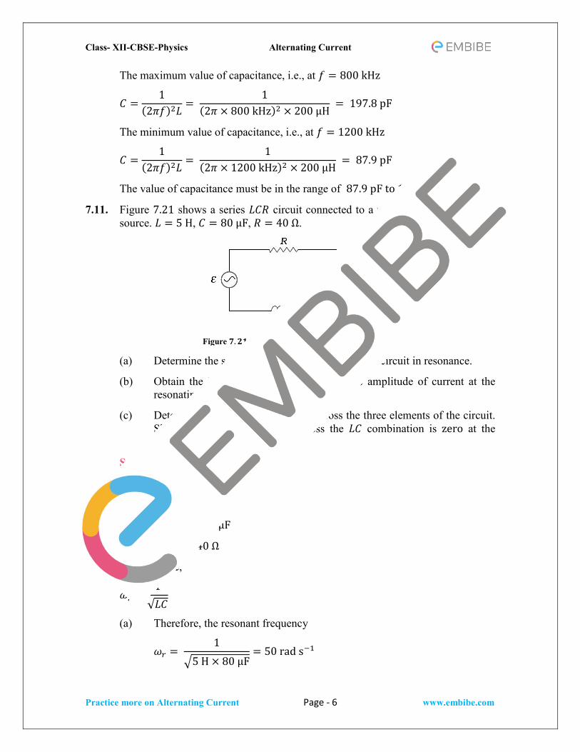
7.11. Figure 7.21 shows a series 𝐿𝐿𝐶𝐶𝑅𝑅 circuit connected to a variable frequency 230 V source. 𝐿𝐿 = 5 H, 𝐶𝐶 = 80 μF, 𝑅𝑅 = 40 Ω.
Figure 𝟕𝟕.𝟐𝟐𝟐𝟐
(a) Determine the source frequency which drives the circuit in resonance.
(b) Obtain the impedance of the circuit and the amplitude of current at the resonating frequency.
(c) Determine the rms potential drops across the three elements of the circuit. Show that the potential drop across the 𝐿𝐿𝐶𝐶 combination is zero at the resonating frequency.
Solution:
Given,
Inductance, 𝐿𝐿 = 5 H
Capacitance, 𝐶𝐶 = 80 μF
Resistance, 𝑅𝑅 = 40 Ω
At resonance,
𝜔𝜔𝑟𝑟 =1
√𝐿𝐿𝐶𝐶
(a) Therefore, the resonant frequency
𝜔𝜔𝑟𝑟 = 1
5 H × 80 μF= 50 rad s−1
Class- XII-CBSE-Physics Alternating Current
Practice more on Alternating Current Page - 7 www.embibe.com
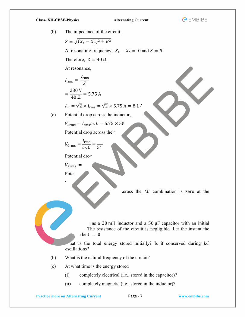
(b) The impedance of the circuit,
𝑍𝑍 = (𝑋𝑋𝐿𝐿 − 𝑋𝑋𝐶𝐶)2 + 𝑅𝑅2
At resonating frequency, 𝑋𝑋𝐶𝐶 – 𝑋𝑋𝐿𝐿 = 0 and 𝑍𝑍 = 𝑅𝑅
Therefore, 𝑍𝑍 = 40 Ω
At resonance,
𝐼𝐼rms = 𝑉𝑉rms𝑍𝑍
=230 V40 Ω
= 5.75 A
𝐼𝐼𝑚𝑚 = √2 × 𝐼𝐼rms = √2 × 5.75 A = 8.1 A
(c) Potential drop across the inductor,
𝑉𝑉𝐿𝐿rms = 𝐼𝐼rms𝜔𝜔𝑟𝑟𝐿𝐿 = 5.75 × 50 × 5 = 1437.5 V
Potential drop across the capacitor,
𝑉𝑉𝐶𝐶rms =𝐼𝐼rms𝜔𝜔𝑟𝑟𝐶𝐶
=5.75
50 × 80 × 10−6= 1437.5 V
Potential drop across the resistor,
𝑉𝑉𝑅𝑅rms = 𝐼𝐼rms𝑅𝑅 = 5.75 × 40 = 230 V
Potential drop across the 𝐿𝐿𝐶𝐶 circuit,
𝑉𝑉𝐿𝐿𝐶𝐶rms = 𝑉𝑉𝐿𝐿rms − 𝑉𝑉𝐶𝐶rms = 0
Hence, the potential drop across the 𝐿𝐿𝐶𝐶 combination is zero at the resonating frequency.
Additional Exercises:
7.12. An 𝐿𝐿𝐶𝐶 circuit contains a 20 mH inductor and a 50 µF capacitor with an initial charge of 10 mC. The resistance of the circuit is negligible. Let the instant the circuit is closed be t = 0.
(a) What is the total energy stored initially? Is it conserved during 𝐿𝐿𝐶𝐶 oscillations?
(b) What is the natural frequency of the circuit?
(c) At what time is the energy stored
(i) completely electrical (i.e., stored in the capacitor)?
(ii) completely magnetic (i.e., stored in the inductor)?

Class- XII-CBSE-Physics Alternating Current
Practice more on Alternating Current Page - 8 www.embibe.com
(d) At what times is the total energy shared equally between the inductor and the capacitor?
(e) If a resistor is inserted in the circuit, how much energy is eventually dissipated as heat?
Solution:
Given,
Charge on the capacitor, 𝑄𝑄 = 10 mC,
Inductance, 𝐿𝐿 = 20 mH
Capacitance, 𝐶𝐶 = 50 μF
(a) The total energy stored initially at t = 0,
𝐸𝐸 =𝑄𝑄2
2𝐶𝐶
𝐸𝐸 = (10 mC)2
2 × 50 μF= 1 J
Yes, total energy will remain conserved during the oscillation.
(b) The natural frequency of the circuit,
𝜔𝜔𝑟𝑟 =1
√𝐿𝐿𝐶𝐶
𝜔𝜔𝑟𝑟 = 1
20 mH × 50 μF= 103 rad s−1
𝑓𝑓𝑟𝑟 =𝜔𝜔𝑟𝑟2𝜋𝜋
=103
2𝜋𝜋 rad s−1 = 159 s−1
(c) (i) For time period (𝑇𝑇 = 1𝜋𝜋
= 1159
= 6.28 ms), total charge on the capacitor at time t,
Q′ = Q cos 2𝜋𝜋𝜋𝜋𝑇𝑇
For energy stored in electrical, we can write Q′ = Q.
Hence, it can be inferred that the energy stored in the capacitor is completely electrical at time, t = 0, T
2 ,𝑇𝑇 , 3𝑇𝑇
2 , … ….
(ii) Magnetic energy is maximum when electrical energy is minimum. Hence, it can be inferred that the energy stored in the circuit is completely magnetic at time 𝜋𝜋 = 𝑇𝑇
4 , 3𝑇𝑇
4, 5𝑇𝑇4
,.
Class- XII-CBSE-Physics Alternating Current
Practice more on Alternating Current Page - 9 www.embibe.com
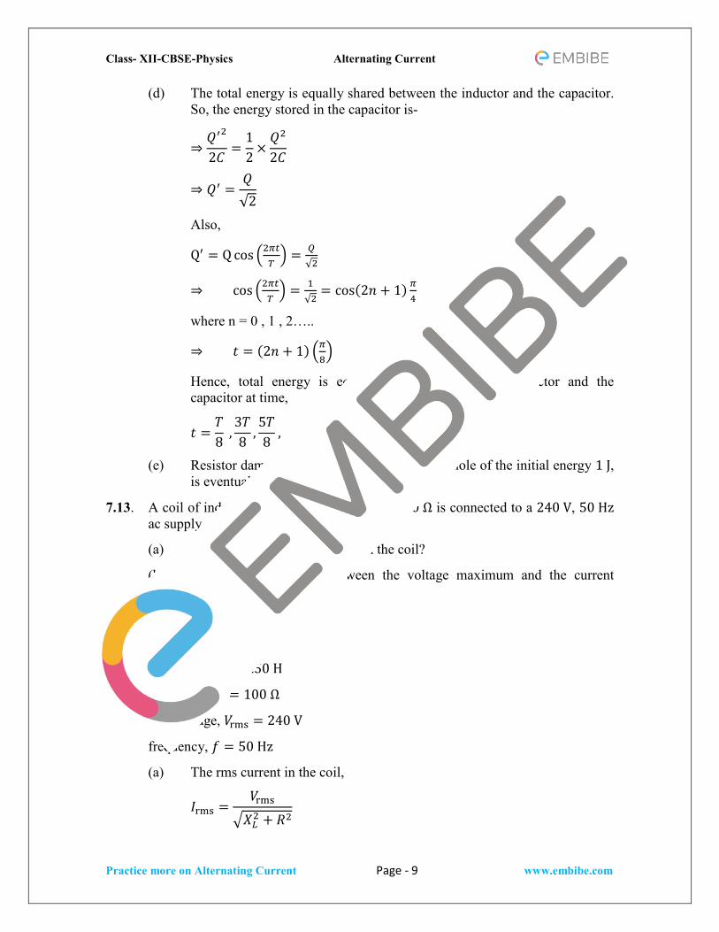
(d) The total energy is equally shared between the inductor and the capacitor. So, the energy stored in the capacitor is-
⇒𝑄𝑄′2
2𝐶𝐶=
12
×𝑄𝑄2
2𝐶𝐶
⇒ 𝑄𝑄′ =𝑄𝑄√2
Also,
Q′ = Q cos 2𝜋𝜋𝜋𝜋𝑇𝑇 = 𝑄𝑄
√2
⇒ cos 2𝜋𝜋𝜋𝜋𝑇𝑇 = 1
√2= cos(2𝑛𝑛 + 1) 𝜋𝜋
4
where n = 0 , 1 , 2…..
⇒ 𝜋𝜋 = (2𝑛𝑛 + 1) 𝜋𝜋8
Hence, total energy is equally shared between the inductor and the capacitor at time,
𝜋𝜋 =𝑇𝑇8
,3𝑇𝑇8
,5𝑇𝑇8
,
(e) Resistor damps out the 𝐿𝐿𝐶𝐶 oscillations. The whole of the initial energy 1 J, is eventually dissipated as heat.
7.13. A coil of inductance 0.50 H and resistance 100 Ω is connected to a 240 V, 50 Hz ac supply.
(a) What is the maximum current in the coil?
(b What is the time lag between the voltage maximum and the current maximum?
Solution:
Given,
Inductance, 𝐿𝐿 = 0.50 H
Resistance, 𝑅𝑅 = 100 Ω
rms voltage, 𝑉𝑉rms = 240 V
frequency, 𝑓𝑓 = 50 Hz
(a) The rms current in the coil,
𝐼𝐼rms =𝑉𝑉rms
𝑋𝑋𝐿𝐿2 + 𝑅𝑅2

Class- XII-CBSE-Physics Alternating Current
Practice more on Alternating Current Page - 10 www.embibe.com
For an inductive circuit,
𝑋𝑋𝐿𝐿 = 2𝜋𝜋 × 50 Hz × 0.5 H = 157 Ω
𝐼𝐼rms =240 V
(157 Ω)2 + (100 Ω)2=
240 V186.1 Ω
= 1.2 A
So, The maximum current in the coil
𝐼𝐼𝑚𝑚 = √2 × 𝐼𝐼rms = √2 × 1.2 A = 1.82 A
(b) In 𝐿𝐿𝑅𝑅 circuit,
If, 𝑉𝑉 = 𝑉𝑉𝑚𝑚 cos𝜔𝜔𝜋𝜋 then,
𝐼𝐼 = 𝐼𝐼𝑚𝑚 cos (𝜔𝜔𝜋𝜋 − 𝑐𝑐)
Voltage is maximum at t = 0 whereas, the current is maximum at = 𝜙𝜙𝜔𝜔
,
Therefore, the time lag between the maximum voltage and maximum current = 𝜙𝜙
𝜔𝜔.
Also, tan𝑐𝑐 = 𝜔𝜔𝐿𝐿𝑅𝑅
= 2𝜋𝜋×50 Hz×0.5 H100 Ω
= 1.57
𝑐𝑐 = tan−1 1.57 = 57.5° =57.5𝜋𝜋180
Timelag = 𝜙𝜙𝜔𝜔
= 57.5𝜋𝜋180×2𝜋𝜋×50
= 3.2 ms.
7.14. Obtain the answers (a) to (b) in Exercise 7.13 if the circuit is connected to a high frequency supply (240 V,10 kHz). Hence, explain the statement that at very high frequency, an inductor in a circuit nearly amounts to an open circuit. How does an inductor behave in a dc circuit after the steady state?
Solution:
Given,
Inductance, 𝐿𝐿 = 0.50 H
Resistance, 𝑅𝑅 = 100 Ω
rms voltage, 𝑉𝑉rms = 240 V
frequency, 𝑓𝑓 = 10 kHz
(a) The maximum current in the coil,
𝐼𝐼m =√2 × 𝑉𝑉rms𝑋𝑋𝐿𝐿2 + 𝑅𝑅2
For an inductive circuit,
Class- XII-CBSE-Physics Alternating Current
Practice more on Alternating Current Page - 11 www.embibe.com
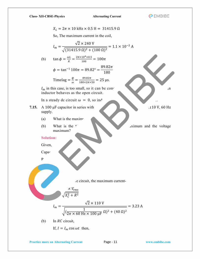
𝑋𝑋𝐿𝐿 = 2𝜋𝜋 × 10 kHz × 0.5 H = 31415.9 Ω
So, The maximum current in the coil,
𝐼𝐼m =√2 × 240 V
(31415.9 Ω)2 + (100 Ω)2= 1.1 × 10⁻² A
(b) tan𝑐𝑐 = 𝜔𝜔𝐿𝐿𝑅𝑅
= 2𝜋𝜋×104×0.5100
= 100𝜋𝜋
𝑐𝑐 = tan−1 100𝜋𝜋 = 89.82° =89.82𝜋𝜋
180
Timelag = 𝜙𝜙𝜔𝜔
= 89.82𝜋𝜋180×2𝜋𝜋×50
= 25 μs.
𝐼𝐼m in this case, is too small, so it can be concluded that at high frequencies an inductor behaves as the open circuit.
In a steady dc circuit ω = 0, so inductor acts as a simple conductor.
7.15. A 100 µF capacitor in series with a 40 Ω resistance is connected to a110 V, 60 Hz supply.
(a) What is the maximum current in the circuit?
(b) What is the time lag between the current maximum and the voltage maximum?
Solution:
Given,
Capacitance, 𝐶𝐶 = 100 μF
Resistance, 𝑅𝑅 = 40 Ω,
rms voltage, 𝑉𝑉rms = 110 V
frequency, 𝑓𝑓 = 60 Hz
(a) For a capacitive circuit, the maximum current-
𝐼𝐼m =√2 × 𝑉𝑉rms𝑋𝑋𝐶𝐶2 + 𝑅𝑅2
𝐼𝐼m =√2 × 110 V
( 12𝜋𝜋 × 60 Hz × 100 μF Ω)2 + (40 Ω)2
= 3.23 A
(b) In 𝑅𝑅𝐶𝐶 circuit,
If, 𝐼𝐼 = 𝐼𝐼𝑚𝑚 cos𝜔𝜔𝜋𝜋 then,

Class- XII-CBSE-Physics Alternating Current
Practice more on Alternating Current Page - 12 www.embibe.com
𝑉𝑉 = 𝑉𝑉𝑚𝑚 cos (𝜔𝜔𝜋𝜋 − 𝑐𝑐)
current is maximum at t = 0 whereas, voltage is maximum at 𝜋𝜋 = 𝜙𝜙𝜔𝜔
,
Therefore, the time lag between the maximum voltage and maximum current = 𝜙𝜙
𝜔𝜔
Also, tan𝑐𝑐 = 1𝜔𝜔𝐶𝐶𝑅𝑅
= 12𝜋𝜋×60 Hz×100 μF×100 Ω
= 0.66
𝑐𝑐 = tan−1 0.66 = 33.56° =33.56𝜋𝜋
180
time lag = 𝜙𝜙𝜔𝜔
= 33.56𝜋𝜋180×2𝜋𝜋×60
= 1.55 ms.
7.16. Obtain the answers to (a) and (b) in Exercise 7.15 if the circuit is connected to a 110 V, 12 kHz supply? Hence, explain the statement that a capacitor is a conductor at very high frequencies. Compare this behaviour with that of a capacitor in a dc circuit after the steady state.
Solution:
Given,
Capacitance, 𝐶𝐶 = 100 μF
Resistance, 𝑅𝑅 = 40 Ω,
rms voltage, 𝑉𝑉rms = 110 V
frequency, 𝑓𝑓 = 12 kHz
(a) For a capacitive circuit, the maximum current-
𝐼𝐼m =√2 × 𝑉𝑉rms𝑋𝑋𝐶𝐶2 + 𝑅𝑅2
𝐼𝐼m =√2 × 110 V
( 12𝜋𝜋 × 12 kHz × 100 μF Ω)2 + (40 Ω)2
= 3.88 A
(b) tan𝑐𝑐 = 1𝜔𝜔𝐶𝐶𝑅𝑅
= 12𝜋𝜋×12 kHz×100 μF×100 Ω
= 196𝜋𝜋
𝑐𝑐 = tan−11
96𝜋𝜋= 0.2° =
0.2𝜋𝜋180
rad
Timelag = 𝜙𝜙𝜔𝜔
= 0.2𝜋𝜋180×2𝜋𝜋×12×103
= 0.04 μs.
Class- XII-CBSE-Physics Alternating Current
Practice more on Alternating Current Page - 13 www.embibe.com
Hence, 𝑐𝑐 tends to become 0 at high frequencies. At a high frequency, capacitor 𝐶𝐶 acts as a conductor. In a dc circuit, after the steady state is achieved, 𝜔𝜔 = 0. Hence, capacitor 𝐶𝐶 amounts to an open circuit.
7.17. Keeping the source frequency equal to the resonating frequency of the series 𝐿𝐿𝐶𝐶𝑅𝑅 circuit, if the three elements, 𝐿𝐿, 𝐶𝐶, and 𝑅𝑅 are arranged in parallel, show that the total current in the parallel 𝐿𝐿𝐶𝐶𝑅𝑅 circuit is minimum at this frequency. Obtain the current rms value in each branch of the circuit for the elements and source specified in Exercise 7.11 for this frequency.
Solution:
Given,
rms voltage, 𝑉𝑉 = 230 V
Inductance, 𝐿𝐿 = 5 H
Resistance, 𝑅𝑅 = 40 Ω
Capacitance,𝐶𝐶 = 80 μF
As the circuit elements are arranged in parallel, the impedance of the circuit is given by,
1𝑍𝑍2
=1𝑋𝑋𝐿𝐿2
+1𝑋𝑋𝐶𝐶2
Also, source frequency is equal to the resonance frequency-
𝜔𝜔 =1
√𝐿𝐿𝐶𝐶 =
15 H × 80 μF
= 50 rad s−1
As the value of 𝑍𝑍 is maximum at this frequency. Hence, the total current will be minimum.
The rms current in the inductor,
𝐼𝐼𝐿𝐿 =𝑉𝑉𝜔𝜔𝐿𝐿
=230
50 × 5= 0.92 A
The rms current in the capacitor,
𝐼𝐼𝐿𝐿 = 𝑉𝑉𝜔𝜔𝐶𝐶 = 230 × 50 × 80 × 10−6 = 0.92 A
The rms current in the resistor,
𝐼𝐼𝑅𝑅 =𝑉𝑉𝑅𝑅
=230 40
= 5.75 A
7.18. A circuit containing a 80 mH inductor and a 60 µF capacitor in series is connected to a 230 V, 50 Hz supply. The resistance of the circuit is negligible.
(a) Obtain the current amplitude and rms values.

Class- XII-CBSE-Physics Alternating Current
Practice more on Alternating Current Page - 14 www.embibe.com
(b) Obtain the rms values of potential drops across each element.
(c) What is the average power transferred to the inductor?
(d) What is the average power transferred to the capacitor?
(e) What is the total average power absorbed by the circuit? [‘Average’ implies ‘averaged over one cycle’.]
Solution:
Here,
Inductance, 𝐿𝐿 = 80 mH
Capacitance, 𝐶𝐶 = 60 μF
rms voltage, 𝑉𝑉 = 230 V
Frequency, 𝑓𝑓 = 50 Hz
(a) 𝜔𝜔 = 2𝜋𝜋𝑓𝑓 = 2π × 50 Hz = 100π rads−1
current amplitude,
𝐼𝐼𝑚𝑚 = √2 ×𝑉𝑉rms𝑍𝑍
=𝑉𝑉rms√2𝑋𝑋𝐿𝐿 − 𝑋𝑋𝐶𝐶
=230 × √2
100𝜋𝜋 × 80 × 10−3 − 1100𝜋𝜋 × 60 × 10−6
= −11.6 A
rms current,
𝐼𝐼rms =𝐼𝐼m√2
=−11.63√2
= −8.24 A
(b) rms value of potential drop across the inductor,
𝑉𝑉𝐿𝐿rms = 𝐼𝐼rms × 𝑋𝑋𝐿𝐿 = 8.24 × 100𝜋𝜋 × 80 × 10−3 = 207 V
rms voltage across the inductor,
𝑉𝑉𝐶𝐶rms = 𝐼𝐼rms × 𝑋𝑋𝐶𝐶 = 8.24 ×1
100𝜋𝜋 × 60 × 10−6= 437 V
(c) As the phase difference between voltage and current through the inductor is π
2 , the average power transferred over a complete cycle by the source to
inductor will always be zero.
𝑃𝑃I,avg = 0.
(d) For 𝐶𝐶, voltage lags by 𝜋𝜋/2. As the phase difference between voltage and current through the capacitor is 𝜋𝜋/2, the average power transferred over a complete cycle by the source to inductor will always be zero.
Class- XII-CBSE-Physics Alternating Current
Practice more on Alternating Current Page - 15 www.embibe.com
𝑃𝑃I,avg = 0.
(e) As there is no average power transfer over a complete cycle by the source to the circuit elements, so the average power absorbed by the circuit is zero.
7.19. Suppose the circuit in Exercise 7.18 has a resistance of 15 Ω. Obtain the average power transferred to each element of the circuit, and the total power absorbed.
Solution:
Here,
Inductance, 𝐿𝐿 = 80 mH
Capacitance, 𝐶𝐶 = 60 μF
rms voltage 𝑉𝑉 = 230 V
Frequency, 𝑓𝑓 = 50 Hz
𝜔𝜔 = 2𝜋𝜋𝑓𝑓 = 2π × 50 Hz = 100π rads−1
Resistance, 𝑅𝑅 = 15 Ω
The impedance of the circuit –
𝑍𝑍 = (𝑋𝑋𝐿𝐿 − 𝑋𝑋𝐶𝐶)2 + 𝑅𝑅2
= 100𝜋𝜋 × 80 × 10−3 −1
100𝜋𝜋 × 60 × 10−62
+ 152 = 31.728 Ω
Current following in the circuit-
𝐼𝐼rms =𝑉𝑉𝑍𝑍
=230 V
31.72 Ω = 7.25 A
The average power transferred to the resistor,
𝑃𝑃𝑅𝑅 = 𝐼𝐼rms2 𝑅𝑅 = 7.252 × 15 = 791 W
The average power transferred to the resistor and capacitor, 𝑃𝑃𝐶𝐶 = 𝑃𝑃𝐼𝐼 = 0
As the average power transferred to inductor and capacitor is zero in one complete cycle. Hence, the total transferred is 791 W.
7.20. A series 𝐿𝐿𝐶𝐶𝑅𝑅 circuit with 𝐿𝐿 = 0.12 H, 𝐶𝐶 = 480 nF, 𝑅𝑅 = 23 Ω is connected to a 230 V variable frequency supply.
(a) What is the source frequency for which current amplitude is maximum? Obtain this maximum value.

Class- XII-CBSE-Physics Alternating Current
Practice more on Alternating Current Page - 16 www.embibe.com
(b) What is the source frequency for which average power absorbed by the circuit is maximum? Obtain the value of this maximum power.
(c) For which frequencies of the source is the power transferred to the circuit half the power at resonant frequency? What is the current amplitude at these frequencies?
(d) What is the Q − factor of the given circuit?
Solution:
Given,
Inductance, 𝐿𝐿 = 0.12 H
Capacitance, 𝐶𝐶 = 480 nF
rms voltage, 𝑉𝑉 = 230 V
Resistance, 𝑅𝑅 = 23 Ω
(a) At resonance the impedance of the circuit will be minimum, resulting in maximum current in the circuit. This frequency is given by-
𝜔𝜔𝑟𝑟 =1
√𝐿𝐿𝐶𝐶=
1√0.12 × 480 × 10−9
= 4167 rad s−1
𝑓𝑓𝑟𝑟 =𝜔𝜔𝑟𝑟2𝜋𝜋
= 663 s−1
The maximum current is given by,
𝐼𝐼m = √2 ×𝑉𝑉𝑅𝑅
= √2 ×23023
= 10√2A
(b) The maximum average power is given by,
𝑃𝑃avg,max =12𝐼𝐼m2 𝑅𝑅 =
12
× 10√22
× 23 = 2300 W
(c) The two angular frequencies for which the power transferred to the circuit is half the power at the resonant frequency,
𝜔𝜔 = 𝜔𝜔𝑟𝑟 ± Δω
Where,
Δ𝜔𝜔 =𝑅𝑅2𝐿𝐿
=23
2 × 0.12= 95.8 rad s−1
Δ𝑓𝑓 =Δ𝜔𝜔2𝜋𝜋
= 15.2 Hz
Hence, at frequencies 648 Hz and 678 Hz the power absorbed is half the peak power.
Class- XII-CBSE-Physics Alternating Current
Practice more on Alternating Current Page - 17 www.embibe.com
The current amplitude at these frequencies can be given as,
𝐼𝐼′ =𝐼𝐼m√2
=10√2√2
= 10
(d) Q-factor of the circuit is given by,
𝑄𝑄 =𝜔𝜔𝑟𝑟𝐿𝐿𝑅𝑅
=4167 × 0.12
23= 21.7
7.21. Obtain the resonant frequency and 𝑄𝑄 − factor of a series 𝐿𝐿𝐶𝐶𝑅𝑅 circuit with 𝐿𝐿 =3 H, 𝐶𝐶 = 27 μF, and 𝑅𝑅 = 7.4 Ω. It is desired to improve the sharpness of the resonance of the circuit by reducing its ‘full width at half maximum’ by a factor of 2. Suggest a suitable way.
Solution:
Given,
Inductance, 𝐿𝐿 = 3 H
Capacitance, 𝐶𝐶 = 27 μF
Resistance, 𝑅𝑅 = 7.4 Ω
Resonant frequency,
𝜔𝜔𝑟𝑟 =1
√𝐿𝐿𝐶𝐶=
1√3 × 27 × 10−6
= 111 rad s−1
𝑄𝑄 − factor of the circuit,
𝑄𝑄 =𝜔𝜔𝑟𝑟𝐿𝐿𝑅𝑅
=111 × 3
7.4= 45
For improvement in sharpness of resonance by a factor of 2, 𝑄𝑄 should be doubled. To double 𝑄𝑄 without changing frequency 𝑅𝑅 should be reduced to half, i.e., to 3.7 Ω.
7.22. Answer the following questions:
(a) In any ac circuit, is the applied instantaneous voltage equal to the algebraic sum of the instantaneous voltages across the series elements of the circuit? Is the same true for rms voltage?
(b) A capacitor is used in the primary circuit of an induction coil.
(c) An applied voltage signal consists of a superposition of a dc voltage and an ac voltage of high frequency. The circuit consists of an inductor and a capacitor in series. Show that the dc signal will appear across C and the ac signal across L.
(d) A choke coil in series with a lamp is connected to a dc line. The lamp is seen to shine brightly. Insertion of an iron core in the choke causes no
Class- XII-CBSE-Physics Alternating Current
Practice more on Alternating Current Page - 18 www.embibe.com
change in the lamp’s brightness. Predict the corresponding observations if the connection is to an ac line.
(e) Why is choke coil needed in the use of fluorescent tubes with ac mains? Why can we not use an ordinary resistor instead of the choke coil?
Solution:
(a) The voltage applied will be equal to the average sum of the instantaneous voltage across the circu it's series elements and will be true for any ac circuit. But the voltages across different elements may not be in phase in the case of rms Voltage In the case of rms voltage, therefore, the statement is not true.
(b) When the circuit is broken, the capacitor is charged with a high induced voltage and the capaci tor is used in an induction coil's primary circuit to avoid sparks in the circuit.
(c) For dc signals, an inductor (L) impedance is negligible, but a capacitor impedance is very high. The dc signal will be appearing across the capacitor (C).In the case of a high frequency ac signal, an inductor (L) impedance will be high and a capacitor (C) impedance will be very low. A high frquency ac signal will therefore appear across the inductor (L).
(d) When an iron core is inserted into the choke coil in series with a lamp connected to the ac line,the lamp will glow dimly, and this is because the iron core and the choke coil increase the circuit impedance.
(e) The choke coil reduces the tube voltage without a lot of power being wasted. So, when using fluorescent tubes with ac mains, the choke coil is needed.An ordinary resistor wastes power in the form of heat so that the use of fluorescent tubes with ac mains cannot use an ordinary resistor instead of a choke coil.
7.23. A power transmission line feeds input power at 2300 V to a stepdown transformer with its primary windings having 4000 turns. What should be the number of turns in the secondary in order to get output power at 230 V?
Solution:
Given,
Input voltage, 𝑉𝑉1 = 2300 V
Input voltage, 𝑉𝑉2 = 230 V
No. of turns in the primary coil, 𝑛𝑛1 = 4000
Using the formula for transformers, we get
𝑉𝑉2𝑉𝑉1
=𝑛𝑛2𝑛𝑛1
Class- XII-CBSE-Physics Alternating Current
Practice more on Alternating Current Page - 19 www.embibe.com
Or, 𝑛𝑛2 = 𝑛𝑛1 × 𝑉𝑉2𝑉𝑉1
= 4000 × 2302300
= 400 turns
7.24. At a hydroelectric power plant, the water pressure head is at a height of 300 m, and the water flow available is 100 m3s–1. If the turbine generator efficiency is 60%, estimate the electric power available from the plant (𝑔𝑔 = 9.8 ms–2).
Solution:
Given,
Height of water pressure head, ℎ = 300 m
The volume of water flown in 1 sec, V = 100 m3
Mass of water, m = 100 × 103 = 105 kg
Efficiency, 𝑒𝑒 = 60%
The potential energy of water during one second = 𝑚𝑚𝑔𝑔ℎ = 105 × 9.8 × 300 =29.4 × 10⁷ J s−1
Efficiency,
𝑒𝑒 =output powerinput power
output power = 𝑒𝑒 × input power = 0.6 × 294 × 106 = 176 MW
Hence, 176 MW of power is available from the plant.
7.25. A small town with a demand of 800 kW of electric power at 220 V is situated 15 km away from an electric plant generating power at 440 V. The resistance of the two wire line carrying power is 0.5 Ω per km. The town gets power from the line through a 4000 − 220 V step-down transformer at a sub-station in the town.
(a) Estimate the line power loss in the form of heat.
(b) How much power must the plant supply, assuming there is negligible power loss due to leakage?
(c) Characterise the step-up transformer at the plant.
Solution:
Given,
The power required, 𝑃𝑃 = 800 × 103 W
Voltage to be supplied, 𝑉𝑉 = 220 V
Voltage at power generating plant, 𝑉𝑉′ = 440 V
The total resistance of two wire line, 𝑅𝑅 = 2 × 15 km × 0.5 Ω per km = 15 Ω
A step-down transformer of rating 4000 − 220 V is used in the sub-station.

Class- XII-CBSE-Physics Alternating Current
Practice more on Alternating Current Page - 20 www.embibe.com
Input Voltage, 𝑉𝑉1 = 4000 V
Output Voltage, 𝑉𝑉2 = 220 V
rms current in the wire lines can be given by,
𝐼𝐼 =𝑃𝑃𝑉𝑉1
=800 × 103
4000= 200 A
(a) Line power loss in the form of heat,
𝑃𝑃′ = 𝐼𝐼2𝑅𝑅 = 2002 × 15 = 600 kW
(b) As there is no power loss due to leakage current. Total power,
𝑃𝑃𝑇𝑇 = 𝑃𝑃 + 𝑃𝑃′ = 800 kW + 600 kW = 1400 kW
(c) Drop across the power line = 𝐼𝐼𝑅𝑅 = 200 × 15 = 3000 Ω
Total voltage transmitted by the plant = 3000 + 4000 = 7000 V
Voltage at power generating plant, 𝑉𝑉′ = 440 V
Hence, the rating of the step-up transformer at the power plant is 440 V − 7000 V.
7.26. Do the same exercise as above with the replacement of the earlier transformer by a 40,000 − 220 V step-down transformer (Neglect, as before, leakage losses though this may not be a good assumption any longer because of the very high voltage transmission involved). Hence, explain why high voltage transmission is preferred?
Solution:
Given,
The power required, 𝑃𝑃 = 800 × 103 W
Voltage to be supplied, 𝑉𝑉 = 220 V
Voltage at power generating plant, 𝑉𝑉′ = 440 V
The total resistance of two wires, 𝑅𝑅 = 2 × 15 km × 0.5 Ω per km = 15 Ω
A step-down transformer of rating 40000 − 220 V is used in the sub-station.
Input Voltage, 𝑉𝑉1 = 40000 V
Output Voltage, 𝑉𝑉2 = 220 V
rms current in the wire lines can be given by,
𝐼𝐼 =𝑃𝑃𝑉𝑉1
=800 × 103
40000= 20 A
(a) Line power loss in the form of heat,
Class- XII-CBSE-Physics Alternating Current
Practice more on Alternating Current Page - 21 www.embibe.com
𝑃𝑃′ = 𝐼𝐼2𝑅𝑅 = 202 × 15 = 6 kW
(b) As there is no power loss due to leakage current. Total power,
𝑃𝑃𝑇𝑇 = 𝑃𝑃 + 𝑃𝑃′ = 800 kW + 6 kW = 806 kW
(c) Drop across the power line = 𝐼𝐼𝑅𝑅 = 20 × 15 = 300 V
Total voltage transmitted by the plant = 300 + 40000 = 40300 V
Voltage at power generating plant, 𝑉𝑉′ = 440 V
Hence, the rating of the step-up transformer at the power plant is 440 V − 40300 V.
Percentage loss during transmission = 6806
× 100 = 0.74%
Percentage loss in the previous exercise = 6001400
× 100 = 43%
The percentage of power loss greatly reduced by high voltage transmission.
⧫ ⧫ ⧫