
CBR Shelters
39
CEMP-ET Engineer Technical Letter 1110-3-498 Department of the Army U.S. Army Corps of Engineers Washington, DC 20314-1000 ETL 1110-3-498 24 February 1999 Engineering and Design DESIGN OF COLLECTIVE PROTECTION SHELTERS TO RESIST CHEMICAL, BIOLOGICAL, AND RADIOLOGICAL (CBR) AGENTS Distribution Restriction Statement Approved for public release; distribution is unlimited.
-
Upload
holisticken -
Category
Documents
-
view
225 -
download
0
Transcript of CBR Shelters
8/3/2019 CBR Shelters
http://slidepdf.com/reader/full/cbr-shelters 1/39
CEMP-ET
Engineer Technical
Letter
1110-3-498
Department of the Army
U.S. Army Corps of EngineersWashington, DC 20314-1000
ETL 1110-3-498
24 February 1999
Engineering and Design
DESIGN OF COLLECTIVE PROTECTION
SHELTERS TO RESIST CHEMICAL,
BIOLOGICAL, AND RADIOLOGICAL (CBR)
AGENTS
Distribution Restriction Statement
Approved for public release; distribution is
unlimited.
8/3/2019 CBR Shelters
http://slidepdf.com/reader/full/cbr-shelters 2/39
CEMP-ET DEPARTMENT OF THE ARMYU.S. ARMY CORPS OF ENGINEERS
Washington, DC 203 14- O00
ETL 1110-3-498
Technical .LetterNo. 1110-3-498 24 February 1999
Engineering and Design
DESIGN OF COLLECTIVE PROTECTION SHELTERS TO RESIST
CMEMICAL, BIOLOGICAL, AND RADIOLOGICAL (CBR) AGENTS
1. n+ This letter provides information and guidance or the design of collective protection(CP) systems. Collective protection provides a toxic-be area (TFA) where personnel canfunction without individual protective equipment such as a mask and protective garments.
2. m. This letter applies to all HQUSACE elements and USACE commands avingmilitary construction and design responsibility.
3. References. Appendix A contains a list of referencedand related publications.
4. Distribti. Approved for public release;distribution is unlimited.
5. wound. Chemical, biological, or radiological agent hreats can come from a wartime
attack, a terrorist attack, or from an industrial accident. Protection can be achieved by evacuatingthe affected area or by using shelters or individual protective equipment (IPE). When evacuationis logistically impossible, passive shelters hat use only sealing measuresprovide limited
, proiection for a short period. For increasedprotection and longer durations, a preplaced collectiveprotection ventilation system s required.
6. Actia. Pending publication of permanent guidance, the enclosed nformation will be used o
assist -IQUSACE, major subordinate conmand;s,district offices, and FOA in the managementand design of collective protection systems.
7. Jmalement~. This letter will have routine application for aI future military projects asdefined in paragraph 8c, ER I 110-345-100.
FOR THE COMMANDER:
7 Appendices Da% P.E.
App A - References Chief, Engineering and Cbnstruction DivisionApp B - Collective Protection for Facilities Directorate of MiIitary ProgramsApp C - Class I, Filtration with PressurizationApp D - Class II, Filtration with Little or No
PressurizationApp E - Filtration EquipmentApp F - Airlocks and PersonnelProcessingApp G - Facility Air Leakage Rates
8/3/2019 CBR Shelters
http://slidepdf.com/reader/full/cbr-shelters 3/39
ETL 1110-3-498
24 Feb 99
A-1
APPENDIX A
REFERENCES
1. ASHRAE “Handbook of Fundamentals,” 1997.
2. ASHRAE 52.1, “Gravimetric and Dust-Spot Procedures for Testing Air-Cleaning Devices
Used in General Ventilation for Removing Particulate Matter,” 1992.
3. ASHRAE Standard 62, “Ventilation for Acceptable Indoor Air Quality,” 1989.
4. ASME AG-1a, Section FC, “Code on Nuclear Air and Gas Treatment,” 1996.
5. ASME N509, “Nuclear Power Plant Air-Cleaning Units and Components,” 1989.
6. ASME N510, “Testing of Nuclear Air Treatment Systems,” 1989.
7. ASME NQA-1, “Quality Assurance Requirements for Nuclear Facility Applications,” 1994.
8. ASTM E779, “Standard Test Method for Determining Air Leakage Rate by Fan
Pressurization,” 1987.
9. EA-C-1704, “Carbon-Activated, Impregnated, Copper-Silver-Zinc-Molybdenum-
Triethylenediamine (ASZM-TEDA),” U.S. Army Edgewood Research, Development and
Engineering Center (ERDEC), Aberdeen Proving Grounds, Maryland, January 1992.
10. ERDEC-TR-336, “Expedient Sheltering In Place: An Evaluation for the Chemical Stockpile
Emergency Preparedness Program,” U.S. Army Edgewood Research, Development and
Engineering Center (ERDEC), Aberdeen Proving Grounds, Maryland, June 1996.
11. FM 3-4, “NBC Protection,” 29 May 1992.
12. IEEE Std-344, “IEEE Recommended Practice for Seismic Qualification of Class 1E
Equipment for Nuclear Power Generating Stations,” 1987.
13. MIL-PRF-32016(EA), “Performance Specification Cell, Gas Phase, Adsorber,”26 November 1997.
14. MIL-STD-282, “Filter Units, Protective Clothing, Gas-Mask Components and Related
Products: Performance-Test Method,” 28 May 1956.
15. MS MIL-F-51079D, “Filter Medium, Fire-Resistant, High-Efficiency,” 17 February 1988.

8/3/2019 CBR Shelters
http://slidepdf.com/reader/full/cbr-shelters 4/39
ETL 1110-3-498
24 Feb 99
A-2
16. NFPA 101, “Life Safety Code,” 1997.
17. TM 5-810-1, “Mechanical Design Heating, Ventilating, and Air Conditioning,” 15 June 1991.
18. TM 5-855-1, “Design and Analysis of Hardened Structures to Conventional Weapons
Effects,” August 1998.
19. UL 586, “High-Efficiency, Particulate, Air Filter Units,” 1996.
20. ER 1110-345-100, “Design Policy for Military Construction.”
8/3/2019 CBR Shelters
http://slidepdf.com/reader/full/cbr-shelters 5/39
ETL 1110-3-498
24 Feb 99
B-1
APPENDIX B
COLLECTIVE PROTECTION FOR FACILITIES
B-1. Collective Protection Design Strategy.
A chemical, biological, or radiological (CBR) airborne threat can come from a wartime attack,
terrorist attack, or from an industrial accident. Protection of personnel during these events can be
achieved by evacuation from the affected area, collective protection sheltering, or individual
protective equipment (IPE).
a. Use of CBR Detectors. Theoretically, automatic detectors can be used to initiate
protective actions such as shutdown of ventilation systems, closing outside air intakes, or turning
on filtration systems. Detection of radiological agents can be performed with off-the-shelf
equipment. Current biological detection technology requires a minimum delay of approximately 15minutes to detect the presence of biological agents. Practical application of chemical detection is
limited by shortcomings in response time, false alarms, broad spectrum capability, maintenance
requirements, cost, and the quantity of sensors needed at air intake locations. For wartime threats,
audible and visual indicators along with detection are used to initiate protective actions. For
terrorist threats, no audible and visual indications announce the attack, other than incapacitation of
people. Thus, application of detectors for terrorist threats should be limited to the following uses:
first entry determination by first responders, monitoring casualties before medical treatment,
determining the extent of the hazard, and determining when protective measures are no longer
required.
b. Wartime Threat . For large scale wartime chemical or biological attack, the facility will bedesigned to provide a toxic-free area (TFA) where personnel can function without IPE. To resist
the penetration of agents into the TFA from long duration exposure, a wartime facility must have a
CBR overpressure filter system that prevents penetration of agents at a wind speed of 40 km/hr
(25 mph). Also required are an outdoor or integral contamination control area (CCA) for
decontamination of personnel and an airlock that prevents contaminated air from entering the TFA
during ingress and egress of personnel.
c. Terrorist Threat . For facilities that require continuous operation during a short duration
threat with little or no warning, such as a terrorist attack, continuous filtration of the ventilation air
intakes is required. To resist the short duration penetration of agents into the TFA, a CBR
filtration system will be required to provide an overpressure that prevents the penetration of agentsthrough the TFA envelope at wind speeds of 12 km/hr (7 mph). This wind speed condition is most
favorable for directing a plume of agent with minimum dispersion toward an outside air intake.
d. Industrial Accidents. To provide passive protection for an exposure of short duration,
sealing measures at the facility envelope and closing outside air intakes will provide limited
protection to the occupants for a short period of time. The level of protection provided by passive
8/3/2019 CBR Shelters
http://slidepdf.com/reader/full/cbr-shelters 6/39
ETL 1110-3-498
24 Feb 99
B-2
means is time dependent. To provide collective protection for a facility that requires continuous
operation either closing of the outside air intakes during the release, or protecting the air intakes
with a CBR filtration system is required.
B-2. Facility Collective Protection Classification.
Existing and new facilities designated to provide collective protection (CP) can be separated into
the three major classes of protection described below.
a. Class I - Filtration with Pressurization. This class of protection is applicable against
wartime military threats that produce a large-scale release of agents over an extended period of
time. Effective protection requires a CBR filtration and overpressure system that resists a
continual large-scale threat in a 40-km/hr (25-mph) wind. The filtration and pressurization system
may be operated continuously or maintained in a standby mode; i.e., energized only when there is a
known threat of attack. An internal or external CCA and an ingress and egress airlock arerequired.
b. Class II - Filtration with Little or No Pressurization. This class of protection is
applicable to a terrorist attack with little or no warning that produces a short duration small-scale
release of agent. Outside air intakes will be protected by continuously operating CBR filtration
units. The filtration system will be sized for the normal facility air intake requirements and need
provide little or no facility overpressure. An airlock is not required, but a vestibule that acts as an
airlock is desirable.
c. Class III - Passive Protection. This class of protection is applicable to a short duration
release such as an industrial accident. Protection is achieved by closing building openings andturning off ventilation systems. The release must be detected and adequate warning must be issued
before protective measures can be applied.
B-3. Guidance.
a. Designation of CBR Protected Facilities. The commander or authority having
jurisdiction determines if facilities are susceptible to a CBR threat and which facilities require
collective protection.
b. Existing Facilities. Existing facilities designated to have a Class I CP overpressure
system will be modified in accordance with Appendix C. Existing facilities designated to have aClass II CP system with little or no pressurization will be modified in accordance with Appendix D.
Expedient passive protection CP sealing measures for existing Class III facilities will be based on
the recommendations in ERDEC-TR-336.
c. New Facilities. New facilities designated as a Class I CP overpressure system, or required
to incorporate design features that ease future installation of a CP system, will incorporate the
8/3/2019 CBR Shelters
http://slidepdf.com/reader/full/cbr-shelters 7/39
ETL 1110-3-498
24 Feb 99
B-3
requirements in Appendix C. Requirements for collective protection for wartime facilities which
include an integral CCA will be designed in accordance with TM 5-855-1 and other criteria as
designated by the using command or authority having jurisdiction. New facilities designated as a
Class II CP system or required to incorporate design features that ease future installation of a CPsystem will incorporate the requirements in Appendix D.
B-4. Additional Assistance.
Additional assistance is available from the Corps of Engineers Protective Design Center at the
address provided below.
U.S. Army Engineer District, Omaha
ATTN: CENWO-ED-S
215 North 17th Street
Omaha, NE 68102-4978
Telephone: (402) 221-4925/4918
8/3/2019 CBR Shelters
http://slidepdf.com/reader/full/cbr-shelters 8/39
ETL 1110-3-498
24 Feb 99
C-1
APPENDIX C
CLASS I, FILTRATION WITH PRESSURIZATION
C-1. Existing Facility Classification.
Existing facilities can be separated into four classes that reflect their potential to support the
integration of a CP system.
a. Class IA. This class of facility is capable of fully integrating the CP overpressure system
with the facility heating, ventilating, and air-conditioning (HVAC) system. The HVAC system
may not be specifically designed for a CP overpressure system, but it is capable of fully maintaining
the facility temperature during CP system operation. The CCA will be outside of the facility or
under an open-air overhang, roofed shelter, or tent.
b. Class IB. The facility HVAC system is capable of partial integration of the CP
overpressure system. The HVAC system may require upgrades to existing ductwork and isolation
of the ductwork used for normal HVAC facility operations. The HVAC system may not be
capable of maintaining original design conditions without modification and may require
supplemental heating and cooling. The CCA will be outside of the facility or under an open-air
overhang, roofed shelter, or tent.
c. Class IC . The facility HVAC system is not capable of integrating the CP overpressure
system. The facility design temperatures cannot be maintained without supplemental heating and
cooling from the CP overpressure system. The CCA will be outside of the facility or under an
open-air overhang, roofed shelter, or tent.
d. Class ID. The facility cannot be sealed economically to maintain an overpressure, but it is
suitable for portable enclosures or liner systems set up internally with advance warning. This type
of arrangement allows the existing HVAC system to partially or fully maintain the facility design
temperature outside the inflatable liner or shelter. Examples are warehouses, hangers, and
maintenance bays.
C-2. Guidance.
New Class I CP facilities will be designed as Class 1A; i.e., capable of maintaining the facility
temperature during collective protection operations. New collective protection facilities with anintegral CCA will be designed in accordance with TM 5-855-1 and other criteria as designated by
the using command having jurisdiction.
8/3/2019 CBR Shelters
http://slidepdf.com/reader/full/cbr-shelters 9/39
ETL 1110-3-498
24 Feb 99
C-2
C-3. Design Requirements.
Major considerations for the design of CP systems for both existing and new facilities are listed
below. Requirements for each item are discussed in subsequent paragraphs.
a. Button-Up Period and Floor Area Requirements.
b. Toxic-Free Area Envelope.
c. Airlock Requirements.
d. Toxic-Free Area Overpressure.
e. Toxic-Free Area Envelope Air Leakage Rate and Sealing Measures.
f. Collective Protection Overpressure System Design.
g. Collective Protection Control System and Operational Requirements.
h. Operation and Maintenance.
C-4. Button-Up Period and Floor Area Requirements.
The CP button-up period is determined by the command or authority having jurisdiction and can
range from several hours to several days. For off-site industrial accidents, the button-up period is
usually less than 24 hours. Button-up periods longer than 24 hours are generally restricted towartime. The button-up period influences the floor area requirements and the amount of
consumable and waste storage. Generally, the button-up period will not significantly affect the
performance of the CP system.
a. Less Than 24 Hours. A button-up period less than 24 hours does not require sleeping
areas. The occupant load will generally be a net 1.86 m /person (20 ft /person) depending upon2 2
the classification of occupancy. The classification of occupancy, as stated in NFPA 101, may
require a higher or lower occupant loading depending upon the building classification. The
occupant loading will be coordinated with the authority having jurisdiction.
b. More Than 24 Hours. A button-up period greater than 24 hours requires sleeping areas.The minimum floor area, with the use of single size beds, is approximately 5.6 m /person (602
ft /person). With the use of bunked beds, the minimum floor area is approximately 2.8 m /person2 2
(30 ft /person).2
C-5. Toxic-Free Area Envelope.
8/3/2019 CBR Shelters
http://slidepdf.com/reader/full/cbr-shelters 10/39
ETL 1110-3-498
24 Feb 99
C-3
The total required TFA floor space is determined from the button-up period, the number of people
sheltered, and the required floor area per person. Generally, large open areas such as common
areas, multipurpose areas, gymnasiums, etc., provide the most efficient floor area for protecting a
large number of personnel. The TFA envelope should include bathroom facilities and, if possible,kitchen facilities.
C-6. Airlock Requirements.
Personnel that ingress and egress the TFA during CP operations must process through an airlock.
The airlock maintains TFA overpressure, prevents the migration of airborne contaminants into the
TFA, and purges contaminants from personnel before they enter the TFA. The number of airlocks
required depends on the number of personnel that ingress and egress during a given time period.
a. Stand-Alone Airlock . For existing facilities, the stand-alone two-stage airlock discussed
in Appendix F will be used. This airlock is designed to process two people into the facility within8 minutes with 4 minutes in the first stage and an additional 4 minutes in the second stage. An
integral 94 L/s (200 cfm) air filtration unit is used to provide the necessary air purge rate upon
which the dwell time is based.
b. Integral Airlock . For new facilities, the integral single-stage airlock discussed in
Appendix F will be incorporated into the vestibule area. The airflow purge rate through the single-
stage airlock will provide a 3 log reduction in contaminants based on equation C-1.
(eq C-1)
where:
Q = airflow, cubic meters per minute
V = airlock volume, cubic meters
T = purge time, minutes
Airlock airflow is driven by internal overpressure from the TFA. Uncontaminated air from the
TFA will enter the airlock near the ceiling and exhaust near the floor. The airflow rate through the
TFA will be monitored by an airflow measuring station or measuring device that can be field
calibrated, and the airflow rate will be displayed at a CP control panel. The airflow rate through
the airlock will be controlled by a flow control damper and backdraft damper. A warning light will
illuminate when the airflow rate drops below design values. The static air pressure drop from theTFA to the airlock and from the airlock to the exterior will not exceed 25 Pa (0.1 inch wg) at each
location, giving a total airlock static pressure drop of not more than 50 Pa (0.2 inch wg).
C-7. Toxic-Free Area Overpressure.
8/3/2019 CBR Shelters
http://slidepdf.com/reader/full/cbr-shelters 11/39
ETL 1110-3-498
24 Feb 99
C-4
The minimum TFA overpressure will be 75 Pa (0.3 inch wg). This corresponds to a wind speed
impact pressure normal to a wall of 40 km/hr (25 mph). After installation of the overpressure
system, it is possible that a TFA pressure higher than the 75 Pa (0.3 inch wg) will result. A higher
pressure provides a higher factor of safety for the CP system and should not be intentionallylowered to maintain a 75 Pa (0.3 inch wg) overpressure.
C-8. Toxic-Free Area Envelope Air Leakage Rate and Sealing Measures.
a. Existing Facilities. To determine the envelope air leakage rate for existing facilities, an
air leakage measurement test using a blower door assembly will be performed in accordance with
ASTM E779. Test data will be plotted on a log-log graph for ease of data extrapolation and
review. Air leakage locations can be identified during pressurization testing when the blower door
assembly is operated in the negative pressure mode and draws outside air into the proposed TFA.
These leakage locations can also be identified by physical inspection or with smoke testing.
Leakage areas will be sealed with a good quality sealant or, if necessary, reconstructed. Weathersealing measures can be expected to achieve leakage reductions in the range from 5 to 50 percent
depending on the type and quality of facility construction. Sealing of the TFA envelope will
reduce the air leakage rate and thus reduce the required amount of filtered air. Sealing measures
must be economical when compared to the cost of the filtration and HVAC equipment and, for
continuously operated CP facilities, energy usage must also be considered. After sealing, a second
blower test will be conducted to determine the final TFA envelope air leakage rate.
b. New Facilities. For new facilities, the TFA envelope air leakage rate will be calculated
using the effective leakage area procedures in the ASHRAE Handbook of Fundamentals. The
leakage calculations will be performed for the TFA envelope including the walls, roofs, floors,
doors, windows, sole plates, mechanical and electrical penetrations, ceiling-wall joints, isolationdampers, etc. The overpressure of the TFA will be used as the differential pressure in determining
the TFA envelope leakage rate. Appendix G will be used as a guide to confirm the TFA envelope
unit leakage rate as determined by the calculations. Care should be taken during design and
construction to ensure that proper sealing of penetrations is performed and that continuous air
leakage control barriers are used in the TFA envelope. A blower door test of the TFA envelope
should be performed to verify the leakage rate and ensure that the CP overpressure filtration
system has sufficient capacity.
C-9. Collective Protection Overpressure System Design.
a. Airflow Filtration Capacity. The airflow capacity of the CP overpressure filtration system
is the sum of the following three components: TFA envelope air leakage rate at the design pressure
differential, the ventilation air intake rate that meets exhaust requirements, and the airlock airflow
necessary to achieve the required purge rate. The CP filtration system blower total static pressure
will be designed to include the filtration system with dirty filters, ductwork system pressure losses,
and the overpressure requirement of the TFA. The HVAC system must be designed, operated, and
maintained to provide uncontaminated air to the TFA. It will be located in a contamination-free
8/3/2019 CBR Shelters
http://slidepdf.com/reader/full/cbr-shelters 12/39
ETL 1110-3-498
24 Feb 99
C-5
mechanical room to insure that negative pressures induced in the ductwork by HVAC equipment
located in the mechanical room will not draw in contaminated air to the protected area. Filtration
systems will conform to Appendix E.
b. HVAC Requirements.
(1) Existing Facilities. For existing facilities, an engineering evaluation will be performed to
determine if the existing HVAC equipment can be used for CP operations to maintain the designed
indoor air temperatures for both the summer and winter design conditions. The final indoor
temperature for the summer and winter design conditions will be coordinated with the user and, if
necessary, mechanical equipment modifications or additional heating and cooling equipment will be
added to meet user requirements. For Class IC facilities that do not require the system to maintain
above freezing indoor conditions during low outdoor ambient conditions, water utilities must be
protected from freezing during CP operations.
(2) New Facilities. For new facilities, the HVAC equipment will be designed to incorporate
the requirements of the CP overpressure system and maintain indoor design conditions. The
outside air intakes will be located in an inaccessible location or secured by use of a standoff
distance that inhibits the direct insertion of contaminants.
(3) Outside Air Occupant Ventilation Rate. The target outside air intake rate per occupant
will conform to ASHRAE Standard 62. If during CP operations the fresh air intake rates required
in ASHRAE Standard 62 cannot be maintained, lower air intake rates can be used. The lower
fresh air intake rates cannot be used for normal operations but only during CP operations.
Different levels of indoor air quality (IAQ) can be used depending upon user requirements and
facility restrictions. To maintain IAQ based upon the ASHRAE Standard 62 acceptable indoorcarbon dioxide level of 0.1 percent, a minimum air intake rate of 7 L/s (15 ft /min) can be used.3
The lower recommended limit of fresh air intake is based on a carbon dioxide limit of 0.5 percent
or a minimum outside intake rate of 1.4 L/s (3 ft /min). However, 2.4 L/s (5 ft /min) should be3 3
used as the practical lower limit. For facilities that cannot meet the carbon dioxide level of 0.1
percent, a carbon dioxide detector will be provided that will alarm at a level 50 percent higher than
the expected carbon dioxide value, but not more than 0.8 percent. Normally, the filtered outside
air intake required to pressurize the TFA will exceed the occupant ventilation rate.
c. TFA Envelope Isolation and Control.
(1) Ductwork. Ductwork that serves the TFA during normal operation but is not requiredduring CP operations will be closed off and isolated by use of low-leakage dampers at the TFA
envelope. During CP operations, the TFA overpressure system will maintain pressure on the
isolation dampers under all conditions and thereby eliminate entrance of contaminated air into the
TFA. Isolation damper position indicators will be included to provide visual identification of the
open and closed positions. Additionally, the isolation damper position will be visually annunciated
8/3/2019 CBR Shelters
http://slidepdf.com/reader/full/cbr-shelters 13/39
ETL 1110-3-498
24 Feb 99
C-6
at the system control panel. The leakage rating of the isolation dampers will be selected based on
an economical comparison of damper leakage and additional filtration capacity.
(2) Doors. Doors at the TFA envelope will be weather sealed to reduce the air leakage rate.The door position will be monitored and visually annunciated at the system control panel.
C-10. Collective Protection Control System and Operational Requirements.
The CP control system will be located in the TFA, preferably in a utility room. The CP system will
be energized by one control panel switch that de-energizes other facility systems not required
during CP system operations. Examples of these systems are normal outside air fans, exhaust fans,
and recirculation fans that are in the building but outside the protected envelope. The control
system will monitor the position of all isolation dampers and doors by use of an annunciator light
at the control panel. All device positions; i.e., either open or closed, will be annunciated at the CP
control panel. A green indicator light will annunciate if the damper or door is in the correctposition during CP system operation. A red indicator light will annunciate if the damper or door is
not in the correct position or if a problem has occurred. The TFA overpressure with reference to
the atmosphere will be monitored and displayed on the CP control panel. To maintain the TFA
overpressure, the airlock doors must not be opened simultaneously.
C-11. Operation and Maintenance.
a. CP System Operational Testing. Standby CP systems should be tested once each month
to ensure that they are in good operating condition. For continuously operated systems, periodic
system monitoring should be performed to ensure the CP system is operating properly.
b. Filter System. In addition to the manufacturer’s recommended maintenance requirements,
the following filter replacement and testing requirements should be performed.
(1) High-Efficiency Particulate Air (HEPA) Filter. The initial resistance of the HEPA filter is
typically 250 Pa (1.0 inch wg). The HEPA filter should be replaced when it is loaded and the static
pressure differential reaches about 750 Pa (3.0 inches wg). The HEPA filter pressure drop will be
monitored at the CP system control panel with annunciation when the dirty filter pressure drop is
reached. The HEPA filter will be mechanically leak tested after filter replacement.
(2) Adsorption Filter. The adsorber filter should be replaced as required in FM 3-4 and
mechanical leak tested with a test gas after filter replacement.
(3) Airflow Testing. The filtration system airflow rate should be periodically tested and re-
balanced as necessary to maintain the design airflow rate. The filtration system should also be
airflow tested after prolonged use. A HEPA filter without a prefilter could be fully loaded after 9
months of continuous use. Utilizing a prefilter will extend the life of the HEPA filter to about 2
years of continuous use.
8/3/2019 CBR Shelters
http://slidepdf.com/reader/full/cbr-shelters 14/39
ETL 1110-3-498
24 Feb 99
C-7
(4) Filtration System Testing. The filtration system will be field leak tested by an
independent testing agency after installation. The system should also be mechanical leak tested
every 12 months and after replacement of the HEPA filter or adsorber filter. The design must
ensure that adequate filter access is provided.
c. Signage. Doors required to be closed during overpressure will be labeled as such on red
background signage. Doors required to remain open during overpressure will be labeled as such
on green background signage.
d. Training. Training should be conducted for all facility personnel that may be called upon
to operate the CP system.
e. Operating Instructions. Operating instructions and system diagrams for the CP system
will be displayed next to the CP system control panel at eye level. Operating instructions will
describe, in short and concise language, the steps required to operate the CP system. All CPsystem control switches and indicators will be clearly marked and identified.
f. Operation and Maintenance Manual. An operation and maintenance manual will be
provided and will contain system operating instructions, emergency operation instructions,
preventive maintenance information, troubleshooting, corrective maintenance, periodic
maintenance recommendations, critical instructions, and a spare parts list.
8/3/2019 CBR Shelters
http://slidepdf.com/reader/full/cbr-shelters 15/39
ETL 1110-3-498
24 Feb 99
D-1
APPENDIX D
CLASS II, FILTRATION WITH LITTLE OR NO PRESSURIZATION
D-1. Facility Classification.
New facilities designated to have a Class II CP system do not require a CCA or an airlock for
personnel ingress or egress, however, a vestibule that acts as an airlock can be used to maintain
overpressure. This class of protection is applicable against a terrorist attack. Vulnerable outside
air intakes are protected by a continuous CBR filtration system sized for the normal facility air
intake requirements.
D-2. Guidance.
a. Existing Facilities. Existing facilities designated to have a Class II CP system will bemodified in accordance with this appendix.
b. New Facilities. New facilities designated to have a Class II CP overpressure system, or
to incorporate design features that ease future installation of a CP system, will incorporate the
requirements discussed in this appendix.
D-3. Design Requirements.
Major considerations for the design of Class II CP systems for both existing and new facilities are
listed below. Requirements for each item are discussed in subsequent paragraphs.
a. Toxic-Free Area Envelope.
b. Toxic-Free Area Overpressure.
c. Toxic-Free Area Envelope Air Leakage Rate.
d. Collective Protection System Design.
e. Collective Protection Operation and Maintenance Requirements.
D-4. Toxic-Free Area Envelope.
The total floor area required for the TFA is simply the area requiring collective protection. For
Class II facilities, required envelope sealing measures will be minimal. Noticeable leakage paths
should be sealed in existing facilities, and sealing measures should be incorporated in the design of
new facilities. Though an airlock is not required for this level of protection, a double entry door
such as a vestibule entrance can be used to maintain overpressure.
8/3/2019 CBR Shelters
http://slidepdf.com/reader/full/cbr-shelters 16/39
ETL 1110-3-498
24 Feb 99
D-2
D-5. Toxic-Free Area Overpressure.
For existing facilities being modified or new facilities being designed with a Class II CP system, the
air intakes will be protected with a CBR filtration system. The TFA will be designed for aminimum overpressure goal of 5 Pa (0.02 inches wg). This overpressure corresponds to a wind
speed impact pressure normal to a wall of 12 km/hr (7 mph). This wind speed condition is most
favorable for directing a plume of agent with minimum dispersion toward an outside air intake.
After installation of the overpressure system, it is possible that a TFA pressure may be higher than
the 5 Pa (0.02 inch wg). A higher pressure provides a higher factor of safety for the CP system
and should not be intentionally lowered to maintain a 5 Pa (0.02 inch wg) overpressure.
a. Existing Facilities. For existing facilities, the ventilation design will be analyzed to
determine if an overpressure can be achieved by supplying additional air through the existing
ventilation system, restricting exhaust airflow rates such as from an economizer air exhaust or from
other building exhaust systems. The IAQ will still be met since the air is simply exhausted throughthe TFA envelope. The IAQ and exhaust airflow rates required by building ventilation codes will
be maintained. If an overpressure can be achieved with the existing ventilation system, an air
leakage measurement test using a blower door assembly will be performed in accordance with
ASTM E779. If an overpressure cannot be achieved in existing facilities, good protection is still
provided by protecting the outside air intakes.
b. New Facilities. For new facilities, overpressure can be achieved by supplying a higher
rate of conditioned fresh air to the TFA than is exhausted. To obtain a TFA minimum over-
pressure of 5 Pa (0.02 inch wg), the additional air required can be approximated by the unit
leakage values presented in Appendix G. In addition, the air leakage calculation procedures in
ASHRAE Handbook of Fundamentals can be used to determine the additional air intakerequirement.
D-6. Toxic-Free Area Envelope Air Leakage Rate.
a. Existing Facilities. For existing facilities, a pressurization test using a blower door
assembly will be performed in accordance with ASTM E779. Test data will be plotted on a log-
log graph for ease of data tabulation, extrapolation, and review. Air leakage locations can be
identified during pressurization testing when the blower door assembly is operated in the negative
pressure mode and draws outside air into the proposed TFA. These leakage locations can also be
identified by physical inspection or with smoke testing. Leakage areas will be sealed with a good
quality sealant or, if necessary, reconstructed. Weather sealing measures can be expected to
achieve leakage reductions in the range from 5 to 50 percent depending on the type and quality of
facility construction. Sealing of the TFA envelope will reduce the air leakage rate and thus reduce
the required amount of filtered air. Sealing measures must be economical when compared to the
cost of the filtration and HVAC equipment and, for continuously operated CP facilities, energy
usage must also be considered. After sealing, a second blower test will be conducted to determine
the final TFA envelope air leakage rate.
8/3/2019 CBR Shelters
http://slidepdf.com/reader/full/cbr-shelters 17/39
ETL 1110-3-498
24 Feb 99
D-3
b. New Facilities. For new facilities, the TFA envelope air leakage rate will be calculated
using the effective leakage area procedures in the ASHRAE Handbook of Fundamentals. The
leakage calculations will be performed for the TFA envelope including the walls, roofs, floors,
doors, windows, sole plates, mechanical and electrical penetrations, ceiling-wall joints, isolationdampers, etc. The overpressure of the TFA will be used as the differential pressure in determining
the TFA envelope leakage rate. Appendix G will be used as a guide to confirm the TFA envelope
unit leakage rate as determined by the calculations. Care should be taken during design and
construction to ensure that proper sealing of penetrations is performed and that continuous air
leakage control barriers are used in the TFA envelope. A blower door test of the TFA envelope
should be performed after construction to verify the leakage rate and ensure that the CP
overpressure filtration system has sufficient capacity.
D-7. Collective Protection System Design.
a. Airflow Filtration Capacity. The airflow capacity of the CP overpressure filtrationsystem is the sum of the following two components: TFA envelope air leakage rate at the design
pressure differential and the ventilation air intake rate that meets the facility exhaust requirements.
The CP filtration system blower total static pressure will be designed to include the filtration
system with dirty filters, ductwork system pressure losses, and the overpressure requirement of the
TFA. The HVAC system must be designed, operated, and maintained to provide uncontaminated
air to the TFA. It will be located in a contamination-free mechanical room to insure that negative
pressures induced in the ductwork by HVAC equipment located in the mechanical room will not
draw in contaminated air to the protected area. Filtration systems will conform to Appendix E.
b. HVAC Design Requirements.
(1) Existing Facilities. For existing facilities, an analysis will be performed to determine if
the existing HVAC equipment can be utilized for CP operations to maintain a slight overpressure.
If necessary, mechanical equipment modifications will be made to existing facilities and increased
equipment capacities provided for new facilities. The HVAC system must be designed, located,
operated, and maintained to provide uncontaminated air to the TFA. The outside air intakes will
be secured to inhibit the direct insertion of contaminants.
(2) New Facilities. For new facilities, the HVAC equipment will be designed to incorporate
the requirements to maintain a slight overpressure and maintain indoor design conditions. The
HVAC system must be designed, located, operated, and maintained to provide uncontaminated air
to the TFA. The outside air intakes will be located in an inaccessible location or secured to inhibitthe direct insertion of contaminants.
(3) Indoor and Outdoor Design Temperatures. Indoor dry and wet bulb design
temperatures and outdoor design temperatures will be determined in accordance with TM 5-810-1,
associated references, and mission requirements.
8/3/2019 CBR Shelters
http://slidepdf.com/reader/full/cbr-shelters 18/39
ETL 1110-3-498
24 Feb 99
D-4
(4) Outside Air Occupant Ventilation Rate. The outside air intake rate per occupant will
conform to ASHRAE Standard 62 and facility mission requirements.
D-8. Collective Protection Operation and Maintenance Requirements.
a. Control System Location. The CP control system will be located in the mechanical
room.
b. CP System Operational Testing. Periodic CP system monitoring should be performed to
ensure it is in good operating condition.
c. Filter System. In addition to the manufacturer’s recommended maintenance
requirements, the filter replacement and testing requirements discussed below should be followed.
(1) HEPA Filter. The initial resistance of the HEPA filter is typically 250 Pa (1.0 inch wg).The HEPA filter should be replaced when it is loaded and the static pressure differential reaches
about 750 Pa (3.0 inches wg). The HEPA filter pressure drop will be monitored at the CP system
control panel with annunciation when the dirty filter pressure drop is reached.
(2) Adsorption Filter. The adsorber filter should be replaced as required in FM 3-4 and
mechanical leak tested with a fluorocarbon refrigerant gas after filter replacement.
(3) Airflow Testing. The filtration system airflow rate should be periodically tested and
rebalanced as necessary to maintain the design airflow rate.
(4) Filtration System Testing. The filtration system will be field leak tested by anindependent testing agency after installation. The system should also be mechanical leak tested
every 12 months and after replacement of the HEPA filter or adsorber filter. The design must
ensure that adequate filter access is provided.
e. Operating Instructions. Operating instructions will describe, in short and concise
language, the steps required to operate the CP system. All CP system control switches and
indicators will be clearly marked and identified.
f. Operation and Maintenance Manual. An operation and maintenance manual will be
provided and will contain system operating instructions, emergency operation instructions,
preventive maintenance information, troubleshooting, corrective maintenance, critical instructions,and a spare parts list.
8/3/2019 CBR Shelters
http://slidepdf.com/reader/full/cbr-shelters 19/39
ETL 1110-3-498
24 Feb 99
E-1
APPENDIX E
FILTRATION EQUIPMENT
E-1. Collective Protection System Design.
If the CP filtration system is located in a contaminated environment; i.e., outside the TFA
envelope, the CP filtration system will be designed as a blow-through system with the blower
located before the CP filtration system. If the CP filtration system is located in a clean
environment; i.e., inside the TFA envelope, and draws in the contaminated air through a ductwork
system, it will be designed as a draw-through system with the blower located after the CP filtration
system. The CP filtration system blower total static pressure will be designed to include the
filtration system with dirty filters, ductwork system pressure losses, and the overpressure
requirement of the TFA.
E-2. Filtration Systems.
The filtration system is the most critical part of the CP overpressure system. A number of filtration
systems are available from both the military and commercial suppliers. If commercial filter systems
are used, the mechanical system designer should have the technical expertise to prepare
specifications that meet military filter system requirements. For continuously operated filter
systems, accessory equipment such as moisture eliminators and large particulate filters will be
considered for protection of the filter system.
a. Military Filtration Systems. Military filtration units are typically provided as
Government-furnished equipment (GFE). Military equipment provided as GFE has the advantageof being pre-approved for use on Government installations, while commercially available
equipment requires additional Government quality testing.
(1) Fan Filter Assembly (FFA) 580. The FFA-580 filtration unit provides chemical
filtration with a designed capacity of 283 L/s (600 cfm) at 3,750 Pa (15.0 inches wg) using a 2.24-
kW (3-HP) motor. The FFA-580 contains a HEPA filter and an ASZM-TEDA carbon adsorber
designed for a residence time of 0.25 seconds. The FFA-580 is designed for standby operation and
is not intended for continuous duty.
(a) Air Tempering. The FFA-580 unit does not provide air tempering of the filtered air.
For Class I and II facilities, the filtered air can be either ducted directly into the facility air handling
unit return ductwork or discharged directly into the TFA. The existing mechanical system
provides tempering of the air and must be located within the TFA envelope. If the FFA-580 unit is
used to pressurize Class III facilities, the filtered outside air will be discharged directly into the
TFA and the TFA temperature will approach outside ambient conditions.
8/3/2019 CBR Shelters
http://slidepdf.com/reader/full/cbr-shelters 20/39
ETL 1110-3-498
24 Feb 99
E-2
(b) Filtered Airflow Rate. The FFA-580 is provided with an adjustable iris valve (variable
diameter orifice) at the blower inlet. The iris valve is used to maintain the airflow rate for differing
field conditions and will be field adjusted to maintain a maximum airflow rate of 311 L/s (660 cfm).
Adjusting the FFA-580 unit for this airflow rate allows the unit to maintain the minimum 283 L/s(600 cfm) airflow rate when the HEPA filter becomes slightly loaded with dirt and atmospheric
dust. Airflow rates above 311 L/s (660 cfm) should be avoided because higher airflow rates
reduce filter adsorption capacity and residence time. The FFA-580 unit does not have a prefilter
and therefore the HEPA filter will load more quickly than a filtration system with a prefilter. The
FFA-580 unit requires periodic airflow testing to ensure it is maintaining an airflow rate in the
range of 283 L/s (600 cfm) to 311 L/s (660 cfm). An airflow rate of 283 L/s (600 cfm) will be
used for design of the overpressure filtered air system and an airflow rate of 311 L/s (660 cfm) will
be used to design the HVAC system heating and cooling loads. The FFA-580 blower unit can be
used for both 50 and 60 Hz power supply. This will result in different airflow rates and static
pressure values and needs to be considered in the facility design. The FFA-580 blower will
produce a calculated temperature rise of 4.4 degrees C (8.0 degrees F) at standard conditions.Actual tested conditions to determine the air temperature rise across the blower unit indicated in
certain conditions the air temperature rise can be higher than the calculated value. It is
recommended that a temperature rise of 5.5 degrees C (10 degrees F) be used across the FFA-580
blower unit.
(2) The M49 Adsorption Filter. The M49 adsorber is a military developed and produced
gas adsorber. Quality control and testing is also provided and managed by the military. The M49
filter comes in two sizes: 283 L/s (600 cfm) and 566 L/s (1,200 cfm). The M49 adsorber is of
modular design and can be stacked in multiples to achieve a higher airflow rate. When compared
to commercially available adsorber filters, the M49 requires only one stage of filtration for an
airflow rate of 566 L/s (1,200 cfm). Therefore, using the M49 will require somewhat less floorspace than a commercial filter system. The M49 pressure drop is approximately 1,750 Pa (7 inches
wg) lower than a comparable commercially available filter. The lower static pressure drop results
in less initial blower cost due to the lower static head requirement. For CP filtration systems that
operate continuously, the lower static pressure drop of the M49 results in lower operating costs.
However, for CP systems that operate only when needed, the energy cost savings will be minor.
The M49 carbon trays are refillable by the Government. The disadvantage of the M49 filter is its
relatively high initial cost compared to commercially available filters. The M49 adsorption filter
requires prefilters, HEPA filters, and test sections or test points similar to commercial filter
systems. To procure the M49 filter, contact the Technical Director, U.S. Army Edgewood
Research, Development and Engineering Center, ATTN: SCBRD-ENP-A/ Fixed Installation
Engineer, 5183 Blackhawk Road, Aberdeen Proving Ground, MD 21010-5423.
b. Commercial Filtration Systems. Commercial filtration systems are of modular sectional
design and each section can filter 165 L/s (350 cfm) to 590 L/s (1,250 cfm) with two stages of
adsorption. The CP overpressure filter system will require, in series, the following filter sections:
roughing filter, prefilter, an initial HEPA filter, either one or two stages of adsorbers, and a final
HEPA filter. The actual type and number of filters required will depend upon what is to be
8/3/2019 CBR Shelters
http://slidepdf.com/reader/full/cbr-shelters 21/39
ETL 1110-3-498
24 Feb 99
E-3
filtered. Test sections can be provided with the filtration system to ease in-place leak testing of the
system, isolate which filter section fails the leak test, and for future leak testing of the filter system.
To test the carbon adsorbers, typically testing injection and sampling ports that are located before
and after the filter system will be adequate in testing a single stage adsorption system. To test twostages of adsorption, a test section will be required between the stages. To test HEPA filters, test
sections will be required for sampling after the HEPA filter. Test ports must be placed at a
location where good mixing will occur or the test ports must be located approximately 10 duct
diameters before and after the filter system. The filter system will be quality assurance tested in
accordance with ASME N510 and MIL-PRF-32016(EA). Current commercial filtration systems
are of nuclear grade safety class design and are designed for use primarily by the nuclear industry.
The commercial filtration systems meet quality assurance requirements for nuclear facility
applications (ASME NQA-1) and generic seismic requirements in IEEE Standard 344.
Commercial filtration systems used for certain applications, primarily for containment, warrant the
use of ASME NQA-1 and IEEE 344.
(1) Filter Housing. The filter housing will be a bag-in and bag-out design conforming to the
applicable sections of ASME N509 and will be constructed of type 304 stainless steel. For
applications where contaminants will be continuously filtered, bags for the bag-in and bag-out
ports will be provided. For applications where contaminants will rarely be filtered, bags for the
bag-in and bag-out ports are not required.
(2) Roughing Filter. Continuously operated filter systems will have a roughing filter with
an average efficiency of 25 to 30 percent when tested in accordance with ASHRAE 52.1. The
roughing filter extends the life of the intermediate filter or prefilter and reduces its change
frequency.
(3) Prefilter. The prefilter or intermediate filter will have an average efficiency of 80 to 85
percent when tested in accordance with ASHRAE 52.1. The prefilter extends the life of the HEPA
filter and reduces its change frequency.
(4) HEPA Filter. The HEPA filter frame and filter media will meet the construction,
material, testing, qualification, and documentation requirements of ASME N509, ASME N510,
and UL 586 and will have a filter efficiency of 99.97 percent at a 0.3 F m diameter particle size
when tested in accordance with the MIL-STD-282 dioctyl phthalate (DOP) test method. The filter
frames will meet the requirements of ASME AG-1a, Section FC. The HEPA filter medium will
meet the requirements of MS MIL-F-51079D.
(5) Adsorption Filter. The adsorber charcoal media will be designed to adsorb aerosol with
a minimum residence time of 0.25 seconds and will meet the requirements of MIL-PRF-
32016(EA). Typically, for commercial filters, two stages are required to achieve the 0.25 second
residence time at airflow rates of 330 L/s (700 cfm) to 590 L/s (1,250 cfm). One stage of
filteradsorption can be used for airflow rates from 165 L/s (350 cfm) to 295 L/s (625 cfm). For
unknown threats and adsorption of volatile agents, ASZM-TEDA carbon conforming to EA-C-
8/3/2019 CBR Shelters
http://slidepdf.com/reader/full/cbr-shelters 22/39
ETL 1110-3-498
24 Feb 99
E-4
1704 will be used. If the threat is known, the use of ASZM-TEDA may not be required. This will
depend upon the chemical volatility of the threat. If agents of higher volatility, such as hydrogen
cyanide and cyangen chloride are not a threat, activated carbon (not impregnated carbon) will
suffice. The static pressure drop through an ASZM-TEDA adsorber that meets the requirementsof MIL-PRF-32016(EA) is approximately 625 Pa (2.5 inches wg) for a 235 L/s (500 cfm)
adsorber. A sample of the ASZM-TEDA carbon must be provided by the filter manufacturer for
testing at the U.S. Army Edgewood Research, Development and Engineering Center (ERDEC) as
stated in MIL-PRF-32016(EA). Funding for ERDEC testing is provided by the user. Filter trays
not contaminated by chemical surety materials or by super toxic materials can be refilled by the
manufacturer, but any contaminated carbon must be disposed of by the owning activity in
accordance with local, state, and federal regulations. A license must be obtained from the U.S.
Department of Commerce before an adsorption filter containing ASZM-TEDA carbon can be
shipped outside the United States.
8/3/2019 CBR Shelters
http://slidepdf.com/reader/full/cbr-shelters 23/39
ETL 1110-3-498
24 Feb 99
F-1
APPENDIX F
AIRLOCKS AND PERSONNEL PROCESSING
F-1. Airlock Description.
Airlocks will be used in Class I facilities where an overpressure must be maintained during
collective protection operations.
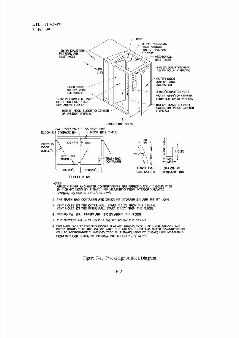
a. Stand-Alone Two-Stage Airlock . As shown in Figure F-1, the stand-alone two-stage
airlock has outer first stage and inner second stage compartments. Clean airflow is provided by a
dedicated filter blower unit connected to the inner compartment at the filtered air inlet. The stand-
alone airlock is designed for a 94 L/s (200 cfm) filter blower unit and intended for retrofitting to
existing facilities. The outer compartment is used to remove protective garments while it is being
continuously purged by the flow of filtered air. After protective garments are removed, personnelenter the inner compartment which is then purged of vapors during the dwell cycle. After the
dwell period, personnel enter the toxic-free area (TFA).
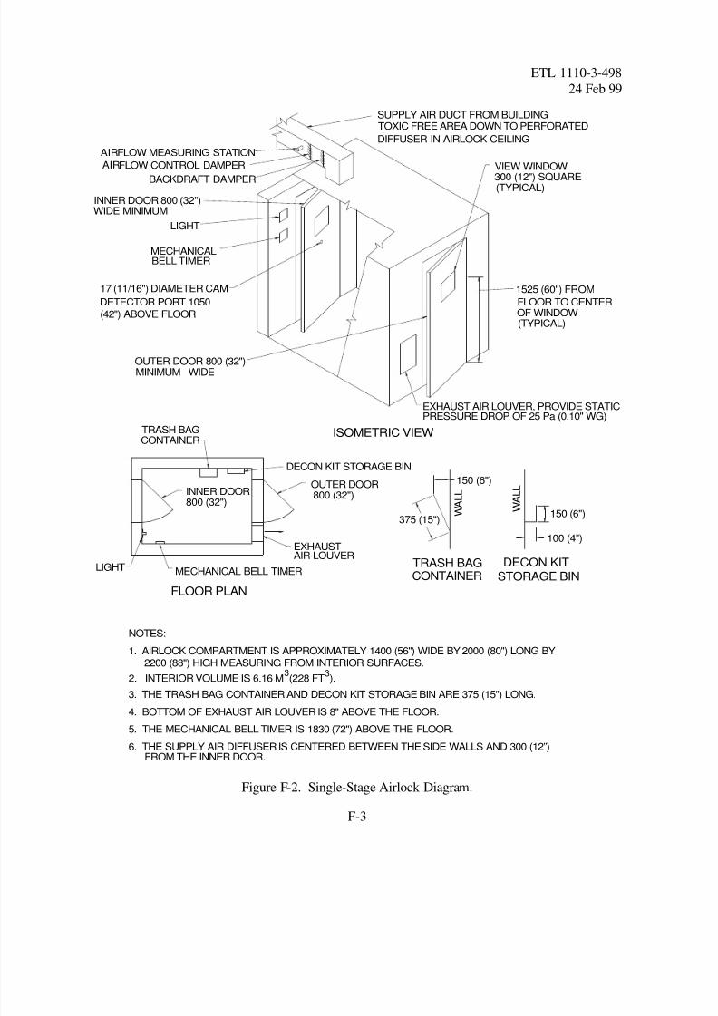
b. Integral Single-Stage Airlock . As shown in Figure F-2, the integral single-stage airlock
is provided with filtered air from the TFA. The overpressure in the TFA will cascade through the
airlock, thereby continuously purging contaminants from the airlock. The design airflow rate will
be determined by equation C-1. The airlock is used to remove protective garments while it is
being continuously purged by the flow of filtered air. After the protective garments are removed,
the airlock will be purged of vapors during the dwell cycle. After the dwell period, personnel
enter the TFA.
F-2. Airlock Features.
The following features are common to an integral or stand-alone airlock.
a. Timers. A mechanical bell timer to time the dwell and purge cycles is required in each
compartment.
b. Windows. A window is required at each compartment to determine if it is occupied.
c. Lights. Lights are required because the interior lacks adequate natural lighting.
d. Purge Vents. The two-stage airlock has fixed rather than adjustable purge vents because
it has a dedicated filter blower unit that makes the airflow rate easy to maintain. For an airlock
without a dedicated filter blower unit, a variable area purge vent or flow control valve is required
to adjust the airflow rate and maintain the required purge rate.
8/3/2019 CBR Shelters
http://slidepdf.com/reader/full/cbr-shelters 24/39
ETL 1110-3-498
24 Feb 99
F-2
Figure F-1. Two-Stage Airlock Diagram.
8/3/2019 CBR Shelters
http://slidepdf.com/reader/full/cbr-shelters 25/39
INNER DOOR 800 (32")WIDE MINIMUM
17 (11/16") DIAMETER CAM
DETECTOR PORT 1050
(42") ABOVE FLOOR
LIGHT
VIEW WINDOW300 (12") SQUARE(TYPICAL)
MECHANICALBELL TIMER
OUTER DOOR 800 (32")WIDEMINIMUM
DECON KIT STORAGE BIN
MECHANICAL BELL TIMER
INNER DOOR800 (32")
OUTER DOOR800 (32")
LIGHT
TRASH BAGCONTAINER
ISOMETRIC VIEW
FLOOR PLAN
1525 (60") FROM
FLOOR TO CENTEROF WINDOW(TYPICAL)
TOXIC FREE AREA DOWN TO PERFORATEDSUPPLY AIR DUCT FROM BUILDING
DIFFUSER IN AIRLOCK CEILING
DAMPERCONTROLFLOWAIR
STATIONMEASURINGFLOWAIR
EXHAUSTAIR LOUVER
150 (6")
150 (6")
100 (4")
W
A L L
W A L L
TRASH BAGCONTAINER
DECON KITSTORAGE BIN
NOTES:
1. AIRLOCK COMPARTMENT IS APPROXIMATELY 1400 (56") WIDE BY 2000 (80") LONG BY
2200 (88") HIGH MEASURING FROM INTERIOR SURFACES.
3. THE TRASH BAG CONTAINER AND DECON KIT STORAGE BIN ARE 375 (15") LONG.
4. BOTTOM OF EXHAUST AIR LOUVER IS 8" ABOVE THE FLOOR.
5. THE MECHANICAL BELL TIMER IS 1830 (72") ABOVE THE FLOOR.
6. THE SUPPLY AIR DIFFUSER IS CENTERED BETWEEN THE SIDE WALLS AND 300 (12”)FROM THE INNER DOOR.
EXHAUST AIR LOUVER, PROVIDE STATICPRESSURE DROP OF 25 Pa (0.10" WG)
2. INTERIOR VOLUME IS 6.16 M (228 FT ).3 3
375 (15")
BACKDRAFT DAMPER
ETL 1110-3-498
24 Feb 99
F-3
Figure F-2. Single-Stage Airlock Diagram.
8/3/2019 CBR Shelters
http://slidepdf.com/reader/full/cbr-shelters 26/39
ETL 1110-3-498
24 Feb 99
F-4
e. Monitoring Port . The monitoring port allows the chemical agent monitor (CAM)
detector inlet to be inserted into the outer compartment by a CAM operator located in the inner
compartment. This allows the CAM operator to determine if there is agent vapor in the outer
compartment. With a negative reading in both the G and H mode (about 10 seconds each), the
operator may determine that a shorter or longer dwell period is required. A second CAM check
for sorbed vapor can then be performed in the inner or second stage compartment.
f. Caulking. Caulking should be applied to all joints to limit uncontrolled air leakage.
g. Paint . Painting the interior and exterior surfaces with epoxy paint is required to
minimize the sorption of liquid and vapor agent.
h. Instructional Signs. Basic personnel processing instructions should be provided on the
outer and inner doors.
i. Clothing Chute or Trash Bag Container . A clothing chute allows contaminated clothing
to be removed from the airlock and discarded outdoors without re-exposure of personnel to the
contaminated atmosphere. As an alternative, plastic trash bags can be placed in the airlock so that
personnel can seal clothing in the bag after removal. The bag is then removed by the next group
entering the airlock. If a clothing chute is not provided, a trash bag container should be provided.
8/3/2019 CBR Shelters
http://slidepdf.com/reader/full/cbr-shelters 27/39
ETL 1110-3-498
24 Feb 99
F-5
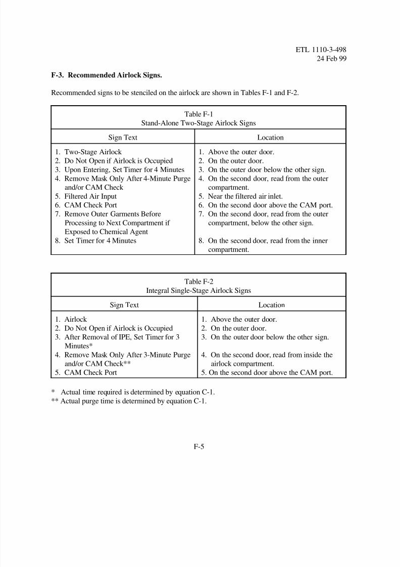
F-3. Recommended Airlock Signs.
Recommended signs to be stenciled on the airlock are shown in Tables F-1 and F-2.
Table F-1
Stand-Alone Two-Stage Airlock Signs
Sign Text Location
1. Two-Stage Airlock
2. Do Not Open if Airlock is Occupied
3. Upon Entering, Set Timer for 4 Minutes
4. Remove Mask Only After 4-Minute Purge
and/or CAM Check 5. Filtered Air Input
6. CAM Check Port
7. Remove Outer Garments Before
Processing to Next Compartment if
Exposed to Chemical Agent
8. Set Timer for 4 Minutes
1. Above the outer door.
2. On the outer door.
3. On the outer door below the other sign.
4. On the second door, read from the outer
compartment.5. Near the filtered air inlet.
6. On the second door above the CAM port.
7. On the second door, read from the outer
compartment, below the other sign.
8. On the second door, read from the inner
compartment.
Table F-2
Integral Single-Stage Airlock Signs
Sign Text Location
1. Airlock
2. Do Not Open if Airlock is Occupied
3. After Removal of IPE, Set Timer for 3
Minutes*
4. Remove Mask Only After 3-Minute Purge
and/or CAM Check**
5. CAM Check Port
1. Above the outer door.
2. On the outer door.
3. On the outer door below the other sign.
4. On the second door, read from inside the
airlock compartment.
5. On the second door above the CAM port.
* Actual time required is determined by equation C-1.
** Actual purge time is determined by equation C-1.
8/3/2019 CBR Shelters
http://slidepdf.com/reader/full/cbr-shelters 28/39
ETL 1110-3-498
24 Feb 99
F-6
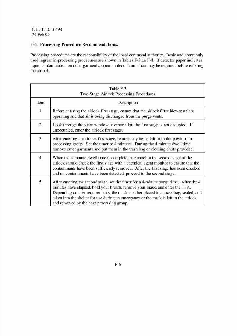
F-4. Processing Procedure Recommendations.
Processing procedures are the responsibility of the local command authority. Basic and commonlyused ingress in-processing procedures are shown in Tables F-3 an F-4. If detector paper indicates
liquid contamination on outer garments, open-air decontamination may be required before entering
the airlock.
Table F-3
Two-Stage Airlock Processing Procedures
Item Description
1 Before entering the airlock first stage, ensure that the airlock filter blower unit isoperating and that air is being discharged from the purge vents.
2 Look through the view window to ensure that the first stage is not occupied. If
unoccupied, enter the airlock first stage.
3 After entering the airlock first stage, remove any items left from the previous in-
processing group. Set the timer to 4 minutes. During the 4-minute dwell time,
remove outer garments and put them in the trash bag or clothing chute provided.
4 When the 4-minute dwell time is complete, personnel in the second stage of the
airlock should check the first stage with a chemical agent monitor to ensure that the
contaminants have been sufficiently removed. After the first stage has been checkedand no contaminants have been detected, proceed to the second stage.
5 After entering the second stage, set the timer for a 4-minute purge time. After the 4
minutes have elapsed, hold your breath, remove your mask, and enter the TFA.
Depending on user requirements, the mask is either placed in a mask bag, sealed, and
taken into the shelter for use during an emergency or the mask is left in the airlock
and removed by the next processing group.
8/3/2019 CBR Shelters
http://slidepdf.com/reader/full/cbr-shelters 29/39
ETL 1110-3-498
24 Feb 99
F-7
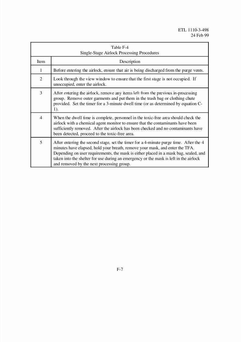
Table F-4
Single-Stage Airlock Processing Procedures
Item Description
1 Before entering the airlock, ensure that air is being discharged from the purge vents.
2 Look through the view window to ensure that the first stage is not occupied. If
unoccupied, enter the airlock.
3 After entering the airlock, remove any items left from the previous in-processing
group. Remove outer garments and put them in the trash bag or clothing chute
provided. Set the timer for a 3-minute dwell time (or as determined by equation C-
1).
4 When the dwell time is complete, personnel in the toxic-free area should check the
airlock with a chemical agent monitor to ensure that the contaminants have been
sufficiently removed. After the airlock has been checked and no contaminants have
been detected, proceed to the toxic-free area.
5 After entering the second stage, set the timer for a 4-minute purge time. After the 4
minutes have elapsed, hold your breath, remove your mask, and enter the TFA.
Depending on user requirements, the mask is either placed in a mask bag, sealed, and
taken into the shelter for use during an emergency or the mask is left in the airlock
and removed by the next processing group.
8/3/2019 CBR Shelters
http://slidepdf.com/reader/full/cbr-shelters 30/39
ETL 1110-3-498
24 Feb 99
G-1
APPENDIX G
FACILITY AIR LEAKAGE RATES
G-1. Facility Envelope Air Leakage Database.
The facility leakage information in Table G-1 results from field leakage testing with a calibrated
blower door assembly. The graphs in Figures G-1 through G-9 show leakage characteristics for
the facility construction types indicated.
G-2. Facility Envelope Construction Types.
Facility wall and roof construction is categorized into the general types below. These categories
are referred to in the leakage characteristic graphs.
a. Wall Construction Types.
(1) Type 1: 25-mm (1-inch) stucco or siding, insulation, 20-mm (¾-inch) plaster or
gypsum.
(2) Type 2: 25-mm (1- inch) stucco or siding, 200-mm (8-inch) concrete block or cast-in-
place concrete, 20-mm (¾-inch) plaster or gypsum.
(3) Type 3: steel siding, insulation, steel siding.
(4) Type 4: 100-mm (4-inch) face brick, insulation, 300-mm (12-inch) concrete block or
cast-in-place concrete, 20-mm (¾-inch) plaster or gypsum.
(5) Type 5: concrete thickness as indicated in millimeters (inches), insulation, 20-mm (¾-
inch) plaster or gypsum. No windows.
b. Roof Construction Types.
(1) Type 1: slag or stone, felt membrane, insulation, steel siding.
(2) Type 2: slag or stone, felt membrane, lightweight concrete.
(3) Type 3: Concrete thickness in mm (inches), insulation.
8/3/2019 CBR Shelters
http://slidepdf.com/reader/full/cbr-shelters 31/39
E T L 1 1 1 0 - 3 -4 9 8
2 4 F e b 9 9
G-2
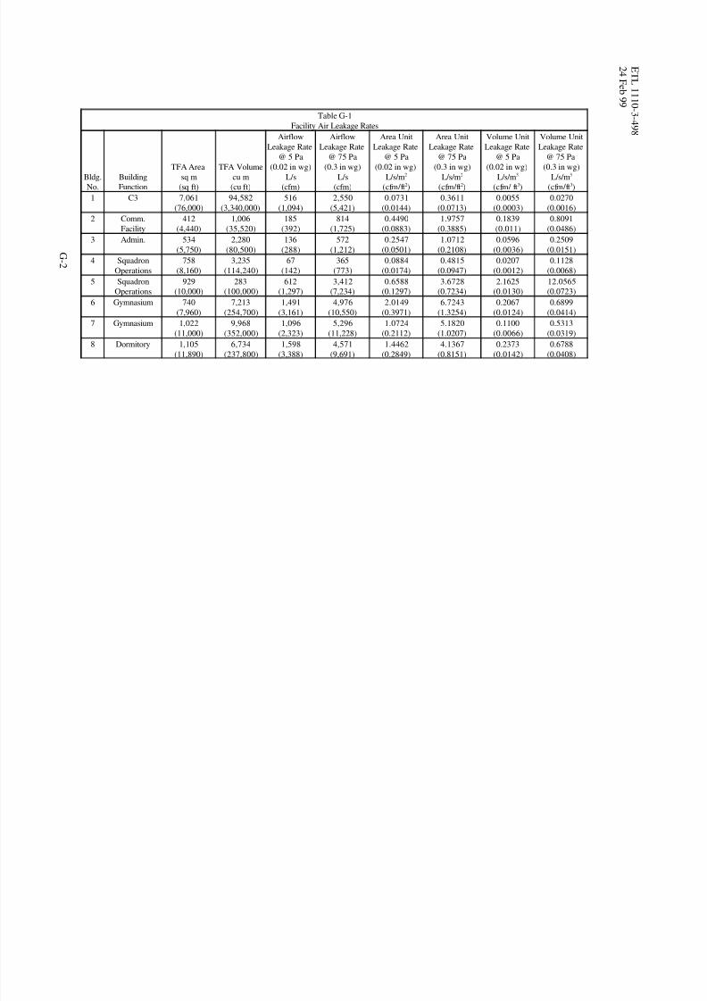
Table G-1
Facility Air Leakage Rates
Bldg.
No.
Building
Function
TFA Areasq m
(sq ft)
TFA Volumecu m
(cu ft)
Airflow
Leakage Rate
@ 5 Pa
(0.02 in wg)L/s
(cfm)
Airflow
Leakage Rate
@ 75 Pa
(0.3 in wg)L/s
(cfm)
Area Unit
Leakage Rate
@ 5 Pa
(0.02 in wg)L/s/m2
(cfm/ft )2
Area Unit
Leakage Rate
@ 75 Pa
(0.3 in wg)L/s/m2
(cfm/ft )2
Volume Unit
Leakage Rate
@ 5 Pa
(0.02 in wg)L/s/m3
(cfm/ ft )3
Volume Unit
Leakage Rate
@ 75 Pa
(0.3 in wg)L/s/m3
(cfm/ft )3
1 C3 7,061
(76,000)
94,582
(3,340,000)
516
(1,094)
2,550
(5,421)
0.0731
(0.0144)
0.3611
(0.0713)
0.0055
(0.0003)
0.0270
(0.0016)
2 Comm.
Facility
412
(4,440)
1,006
(35,520)
185
(392)
814
(1,725)
0.4490
(0.0883)
1.9757
(0.3885)
0.1839
(0.011)
0.8091
(0.0486)
3 Admin. 534
(5,750)
2,280
(80,500)
136
(288)
572
(1,212)
0.2547
(0.0501)
1.0712
(0.2108)
0.0596
(0.0036)
0.2509
(0.0151)
4 Squadron
Operations
758
(8,160)
3,235
(114,240)
67
(142)
365
(773)
0.0884
(0.0174)
0.4815
(0.0947)
0.0207
(0.0012)
0.1128
(0.0068)
5 Squadron
Operations
929
(10,000)
283
(100,000)
612
(1,297)
3,412
(7,234)
0.6588
(0.1297)
3.6728
(0.7234)
2.1625
(0.0130)
12.0565
(0.0723)
6 Gymnasium 740
(7,960)
7,213
(254,700)
1,491
(3,161)
4,976
(10,550)
2.0149
(0.3971)
6.7243
(1.3254)
0.2067
(0.0124)
0.6899
(0.0414)
7 Gymnasium 1,022
(11,000)
9,968
(352,000)
1,096
(2,323)
5,296
(11,228)
1.0724
(0.2112)
5.1820
(1.0207)
0.1100
(0.0066)
0.5313
(0.0319)8 Dormitory 1,105
(11,890)
6,734
(237,800)
1,598
(3,388)
4,571
(9,691)
1.4462
(0.2849)
4.1367
(0.8151)
0.2373
(0.0142)
0.6788
(0.0408)
8/3/2019 CBR Shelters
http://slidepdf.com/reader/full/cbr-shelters 32/39
Internal Pressure, Pa
L e a k a g e R a
t e ,
L / s
1 10 100 1,000100
1,000
10,000
100,000
Wall Type 5: 31000 mm (122") ThickRoof Type 3: 31000 mm (122") Thick
ETL 1110-3-498
24 Feb 99
G-3
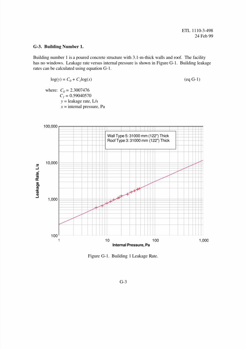
Figure G-1. Building 1 Leakage Rate.
G-3. Building Number 1.
Building number 1 is a poured concrete structure with 3.1-m-thick walls and roof. The facilityhas no windows. Leakage rate versus internal pressure is shown in Figure G-1. Building leakage
rates can be calculated using equation G-1.
log( y) = C + C log( x) (eq G-1)0 1
where: C = 2.30074760
C = 0.590405701
y = leakage rate, L/s
x = internal pressure, Pa
8/3/2019 CBR Shelters
http://slidepdf.com/reader/full/cbr-shelters 33/39
Internal Pressure, Pa
L e a k a g e
R a t e ,
L / s
1 10 100 1,00010
100
1,000
10,000
Wall Type 5: 6600 mm (26") thick, with 8 mm (1/4") Spall PlateRoof Type 3: 6600 mm (26") Thick
ETL 1110-3-498
24 Feb 99
G-4
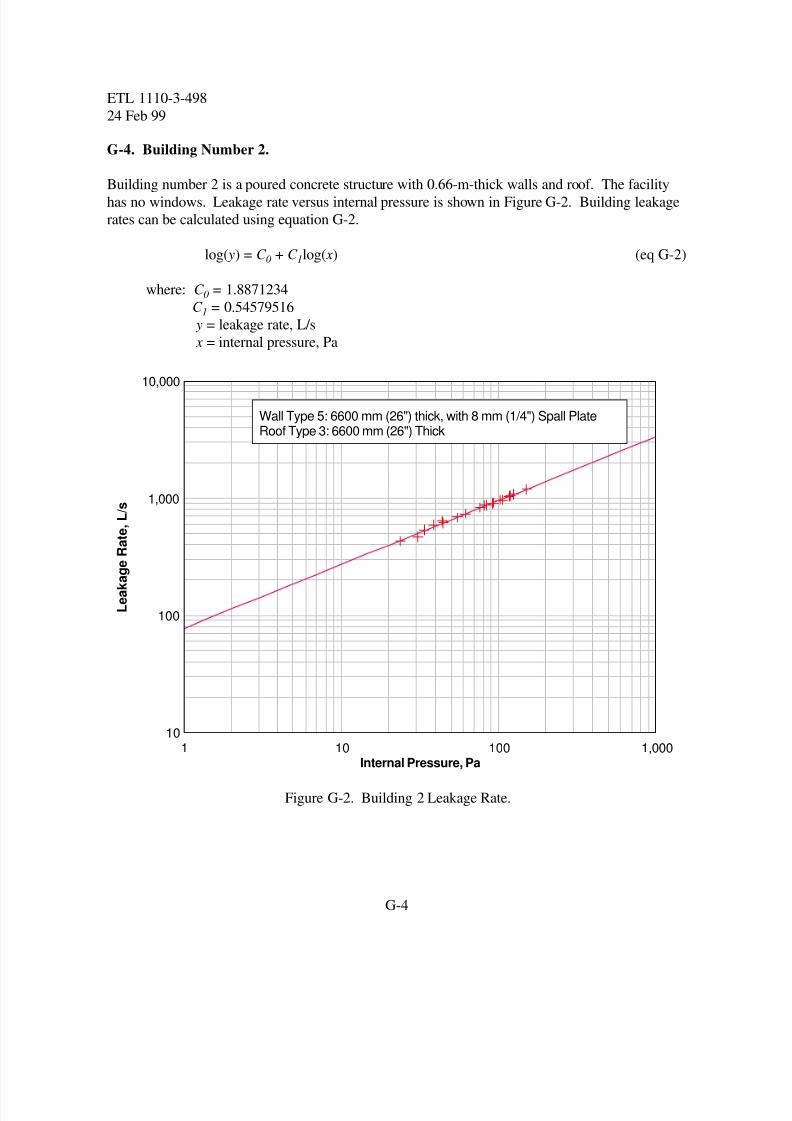
Figure G-2. Building 2 Leakage Rate.
G-4. Building Number 2.
Building number 2 is a poured concrete structure with 0.66-m-thick walls and roof. The facilityhas no windows. Leakage rate versus internal pressure is shown in Figure G-2. Building leakage
rates can be calculated using equation G-2.
log( y) = C + C log( x) (eq G-2)0 1
where: C = 1.88712340
C = 0.545795161
y = leakage rate, L/s
x = internal pressure, Pa
8/3/2019 CBR Shelters
http://slidepdf.com/reader/full/cbr-shelters 34/39
Internal Pressure, Pa
L e a k a g e
R a t e ,
L / s
1 10 100 1,00010
100
1,000
10,000
Wall Type 5: 6600 mm (26") ThickRoof Type 3: 6600 mm (26") Thick
ETL 1110-3-498
24 Feb 99
G-5
Figure G-3. Building 4 Leakage Rate.
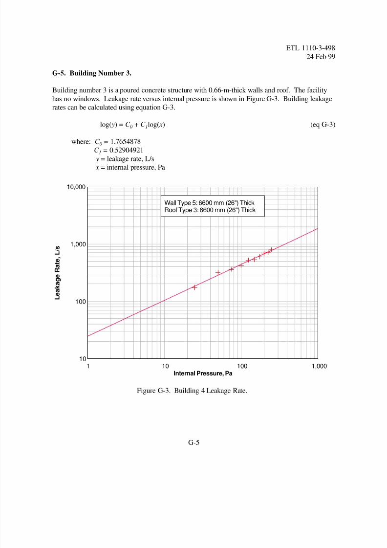
G-5. Building Number 3.
Building number 3 is a poured concrete structure with 0.66-m-thick walls and roof. The facilityhas no windows. Leakage rate versus internal pressure is shown in Figure G-3. Building leakage
rates can be calculated using equation G-3.
log( y) = C + C log( x) (eq G-3)0 1
where: C = 1.76548780
C = 0.529049211
y = leakage rate, L/s
x = internal pressure, Pa
8/3/2019 CBR Shelters
http://slidepdf.com/reader/full/cbr-shelters 35/39
Internal Pressure, Pa
L e a k a g e R a t e ,
L / s
1 10 100 1,00010
100
1,000
10,000
Wall Type 5: 6600 mm (26") ThickRoof Type 3: 6600 mm (26") Thick
ETL 1110-3-498
24 Feb 99
G-6
Figure G-4. Building 3 Leakage Rate.
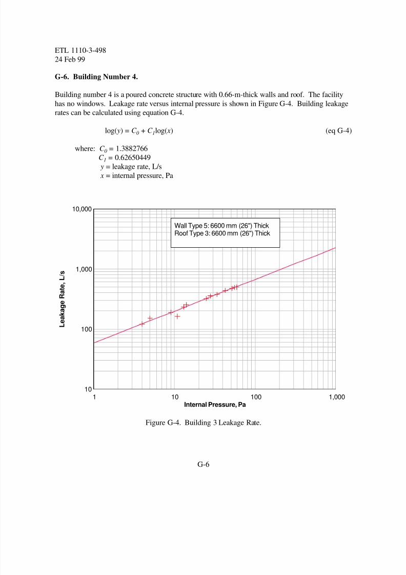
G-6. Building Number 4.
Building number 4 is a poured concrete structure with 0.66-m-thick walls and roof. The facilityhas no windows. Leakage rate versus internal pressure is shown in Figure G-4. Building leakage
rates can be calculated using equation G-4.
log( y) = C + C log( x) (eq G-4)0 1
where: C = 1.38827660
C = 0.626504491
y = leakage rate, L/s
x = internal pressure, Pa
8/3/2019 CBR Shelters
http://slidepdf.com/reader/full/cbr-shelters 36/39
Internal Pressure, Pa
L e a k a g e
R a t e
1 10 100 1,000100
1,000
10,000
100,000
Wall Type 2Roof Type 2
ETL 1110-3-498
24 Feb 99
G-7
Figure G-5. Building 5 Leakage Rate.
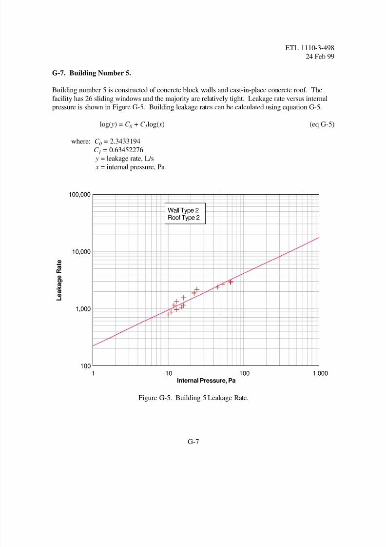
G-7. Building Number 5.
Building number 5 is constructed of concrete block walls and cast-in-place concrete roof. Thefacility has 26 sliding windows and the majority are relatively tight. Leakage rate versus internal
pressure is shown in Figure G-5. Building leakage rates can be calculated using equation G-5.
log( y) = C + C log( x) (eq G-5)0 1
where: C = 2.34331940
C = 0.634522761
y = leakage rate, L/s
x = internal pressure, Pa
8/3/2019 CBR Shelters
http://slidepdf.com/reader/full/cbr-shelters 37/39
Internal Pressure, Pa
L e a k a g e r a t e ,
L / s
1 10 100 1,000100
1,000
10,000
100,000
Wall Type 2Roof Type 1
ETL 1110-3-498
24 Feb 99
G-8
Figure G-6. Building 6 Leakage Rate.
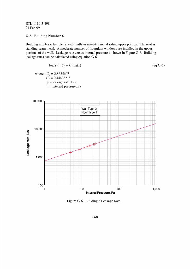
G-8. Building Number 6.
Building number 6 has block walls with an insulated metal siding upper portion. The roof isstanding seam metal. A moderate number of fiberglass windows are installed in the upper
portions of the wall. Leakage rate versus internal pressure is shown in Figure G-6. Building
leakage rates can be calculated using equation G-6.
log( y) = C + C log( x) (eq G-6)0 1
where: C = 2.86256070
C = 0.444962181
y = leakage rate, L/s
x = internal pressure, Pa
8/3/2019 CBR Shelters
http://slidepdf.com/reader/full/cbr-shelters 38/39
Internal Pressure, Pa
L e a k a g e R a
t e ,
L / s
1 10 100 1,000100
1,000
10,000
100,000
Wall Type 2Roof Type 1
ETL 1110-3-498
24 Feb 99
G-9
Figure G-7. Building 7 Leakage Rate.
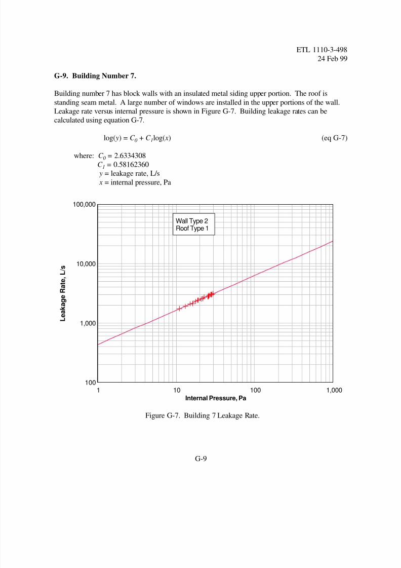
G-9. Building Number 7.
Building number 7 has block walls with an insulated metal siding upper portion. The roof isstanding seam metal. A large number of windows are installed in the upper portions of the wall.
Leakage rate versus internal pressure is shown in Figure G-7. Building leakage rates can be
calculated using equation G-7.
log( y) = C + C log( x) (eq G-7)0 1
where: C = 2.63343080
C = 0.581623601
y = leakage rate, L/s
x = internal pressure, Pa
8/3/2019 CBR Shelters
http://slidepdf.com/reader/full/cbr-shelters 39/39
Internal Pressure, Pa
L e a k a g e R
a t e ,
L / s
1 10 100 1,000100
1,000
10,000
100,000
Wall Type 2Roof Type 2
ETL 1110-3-498
24 Feb 99
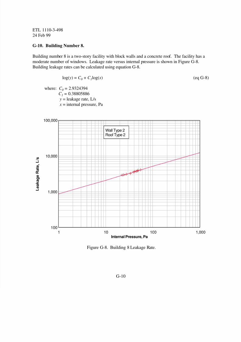
Figure G-8. Building 8 Leakage Rate.
G-10. Building Number 8.
Building number 8 is a two-story facility with block walls and a concrete roof. The facility has amoderate number of windows. Leakage rate versus internal pressure is shown in Figure G-8.
Building leakage rates can be calculated using equation G-8.
log( y) = C + C log( x) (eq G-8)0 1
where: C = 2.93243940
C = 0.388058861
y = leakage rate, L/s
x = internal pressure, Pa