
cb12_eng.pdf
5
PRODUCT DATA SHEET CONTROL BOX CB12 Features: • Mains voltage: 230 & 100/120 V AC 50-60 Hz • Output voltage: 24 V DC • Protection class: IP51 • Colour: black • DIN socket for handset HB40, HB70 or AC P/ACM box • Exchangeable 3.2 m straight mains cable • Electronic overload prot ection (EOP) for all channels • Compact high-power toroidal transformer ensures low power consumption and low electromagnetic emission • Locking mechanism for DIN , jack- and mains sockets • CB12 has a replaceable primary fuse which pr o- tects the CB12 against ov erload. The transformer is protected via a non-replaceable thermal fuse. Options: • Battery back-up: available wit h internally or externally fitted battery sets (BA18) (1.2Ah). The internal charging system cannot charge both internal and external batteries. • Battery alarm indicates low batt ery charge with a buzzer. • Protection class: IP66. The material used is resistent to the m ajority of cleaners and disinfectants used in the hospital and nursing home sector. A control box with IP66 can be used in wash tunnels - see the user manual (LINAK control boxes) for further information. • Colour: grey • Class 1: Earth connections outside the control box and 3-wire mains cable • Automatic mains cut-of f when in standby mode • Audio alarm warns if there is liquid inside the control box (only possible on AT/BT version) • 0.6 m coiled mains cable • Mains fuse replaceable from the outside, ext ra fuse placed on lid Usage: • Duty cycle: 2/18; 2 min. continuous us e followed by 18 min. not in use • For up to 4 actuators: types LA28S, LA30L, LA31, LA32 or LA34 (LA34 with fast motor is possible but only up to 8 amp) and BL4 (only CB12H) (all actuators must be equipped with a jack-plug) • Ambient temperature +5° to +40° C • Medically approved acc ording to EN 60601-1 The CB12 product range features three standard versions, which are ideal for a vast number of medical and industrial applications. In general the CB12 is a transformer operated control unit, which can control up to 4 acuta- tors. The control box features a range of built-in safety devices, increased current cut-off, EAS (Electronic Arc Suppression) and other options such as battery back-up, earth out-let, wet alarm etc. The standard product range: CB12, CB12E with EAS and CB12H with EAS. The CB12E and CB12H with EAS are specially developed for use together with the LA34 actuator.
-
Upload
emilio-medina -
Category
Documents
-
view
213 -
download
0
Transcript of cb12_eng.pdf
7/17/2019 cb12_eng.pdf
http://slidepdf.com/reader/full/cb12engpdf 1/4
P R O D U C T D A T A S H E E T
CONTROL BOXCB12
Features:
• Mains voltage: 230 & 100/120 V AC 50-60 Hz
• Output voltage: 24 V DC
• Protection class: IP51
• Colour: black
• DIN socket for handset HB40, HB70 or ACP/ACM
box
• Exchangeable 3.2 m straight mains cable
• Electronic overload protection (EOP) for all
channels
• Compact high-power toroidal transformer ensures
low power consumption and low electromagnetic emission
• Locking mechanism for DIN, jack- and mains
sockets
• CB12 has a replaceable primary fuse which pro-
tects the CB12 against overload. The transformer
is protected via a non-replaceable thermal fuse.
Options:
• Battery back-up: available with internally or
externally fitted battery sets (BA18) (1.2Ah).
The internal charging system cannot charge both
internal and external batteries.
• Battery alarm indicates low battery charge with
a buzzer.
• Protection class: IP66. The material used is resistent
to the majority of cleaners and disinfectants used
in the hospital and nursing home sector. A control
box with IP66 can be used in wash tunnels - see
the user manual (LINAK control boxes) for further
information.
• Colour: grey
• Class 1: Earth connections outside the control box
and 3-wire mains cable
• Automatic mains cut-off when in standby mode
• Audio alarm warns if there is liquid inside thecontrol box (only possible on AT/BT version)
• 0.6 m coiled mains cable
• Mains fuse replaceable from the outside, extra
fuse placed on lid
Usage:
• Duty cycle: 2/18; 2 min. continuous use followed
by 18 min. not in use
• For up to 4 actuators: types LA28S, LA30L, LA31,
LA32 or LA34 (LA34 with fast motor is possible but
only up to 8 amp) and BL4 (only CB12H) (all
actuators must be equipped with a jack-plug)• Ambient temperature +5° to +40° C
• Medically approved according to EN 60601-1
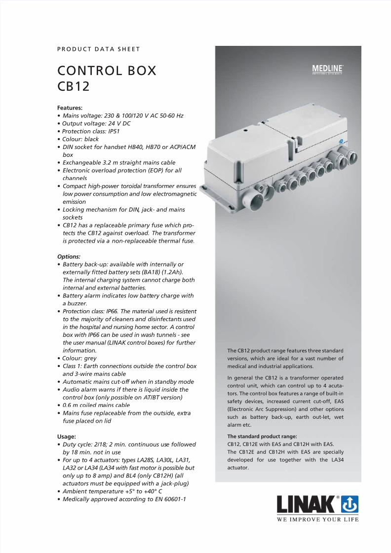
The CB12 product range features three standard
versions, which are ideal for a vast number of
medical and industrial applications.
In general the CB12 is a transformer operated
control unit, which can control up to 4 acuta-tors. The control box features a range of built-in
safety devices, increased current cut-off, EAS
(Electronic Arc Suppression) and other options
such as battery back-up, earth out-let, wet
alarm etc.
The standard product range:
CB12, CB12E with EAS and CB12H with EAS.
The CB12E and CB12H with EAS are specially
developed for use together with the LA34
actuator.

7/17/2019 cb12_eng.pdf
http://slidepdf.com/reader/full/cb12engpdf 2/4
Options for CB12H with EAS:
• Charging indicator circuit for charging indicator on ACP /
ACM (only possible if ch. 4 not mounted, must be specified
parallel or serial connection).
• 8 A current cut-off on channel 1 up or down or channel 2
up or down or any other combination i.e. 10.000 N thrust
for an LA34 with 12 mm pitch standard motor. The currentcut off in the opposite direction will be standard 5.5 A.
• The control box can be chosen with the standard CB12
transformer or the high power transformer from CB14/18
• Special hospital versions: H (most versions demand special
article, see description).
• If battery backup option is chosen, the internal charging
device is always present.
Dimensions:
Options for CB12E:
• Charging indicator circuit for the charging indicator on
ACP/ACM (only possible if ch.4 not mounted, (only serial
connection possible).
• 7A current cut-off on channel 1 up or down or channel 2
up or down or any other combination i.e. 8.000 N thrust for
an LA34 wtih 12 mm pitch and standard motor. The currentcut off in the opposite direction will be standard 5.5 A.
• The control box can be chosen with a standard CB12 trans-
former or a high power transformer from CB14/18.
As standard CB12, CB12E and CB12H can be used with the ACM/ACP ( only serial connection). Use of the ACP and CB12 in
parallel is only possible as a special article and requires additional information.
Note: To ensure compatibility between the ACM/ACP and the CB12, please always specify the type and functionality of the
required ACM/ACP.

7/17/2019 cb12_eng.pdf
http://slidepdf.com/reader/full/cb12engpdf 3/4
BA18Dimensions:
BA18 Battery box (1.2 Ah)Ordering example:
Graph:
The measurements are made in connection with a CB12H with 8 Amp. current cut-off and LA34 with12 mm pitch, -both
randomly selected. The measurements must only be used as guidelines!
How to choose the right transformer type: std. CB12 or high power CB14/18.The secondary voltage in a transformer (voltage for the actuator) decreases when there is a current consumption.
The higher current consumption the more the drop in voltage.
The voltage drop depends on the size of the transformer. - a large transformer will have less voltage drop than a smalltransformer with the same load. When you increase the current cut-off setting the current consumption from the actuatorwill increase, but the voltage drop will also increase. This will result in a drop in actuator speed.
By using a larger transformer, as the one in CB14/18 in CB12, this can partly compensate for the increased voltage drop of anLA34 as LA34 demands more power with heavy loads.
0
2
4
6
8
10
12
14
0 2000 4000 6000 8000 10000 12000
Thrust (N)
S p e e d m m / s
CB18
CB12
0 = Not used
0 = Not used
0 = Not used
- = Not used
Cable length:
- = Not used
IP Protection 0 = IP511 = IP652 = IP66
Colour: 0 = Black
1 = Grey
From 200 mm to 1300 mm with steps of 50 mm
BA18 0 0 - 0200 - 0 0 0
Type: BA18

7/17/2019 cb12_eng.pdf
http://slidepdf.com/reader/full/cb12engpdf 4/4
Specifications subject to change without prior notice.
It is the responsibility of the product user to determine the suitabilityof LINAK A/S products for a specific application. LINAK will at point of
delivery replace/repair defective products covered by the warranty
if promptly returned to the factory. No liability is assumed beyond
such replacement/repair.
C o p y r i g h t ©
L I N A K 0 6 . 0
6 .
M A M 9 - 0 2 - 0 9 0 - I .
C h a p t e r 6 . 8
* By using digits 1-9 increased current cut-off can be chosen on the listed channel combinations: Version E = 7A; version H =8A. All currentlimits are evaluated via common measurements.
** For E or H versions a high power transformer can be chosen (use option =1).*** Battery BA1201 has to be ordered separately for M,P and N versions.The battery is not mounted at LINAK A/S.
CB12Ordering example:
CB12 0 0 0 0 2 0 0 0 0 0 0
Mains cable 2P Mains cable 3P (with earth)
0 straight cable EU A straight cable EU
1 coiled cable EU B coiled cable EU
2 C3 straight cable UK D straight cable UK
4 straight cable JAPAN E
5 straight cable UL F straight cable UL
6 G straight cable CH
7 straight cable AUS H straight cable AUS
8 I
9 without cable J without cable
K coiled cable DK
IP protection: 0 = IP51
2 = IP66 Washable
Voltage input: 0 = 230V 3 = 230V without fuse cover
1 = 120V 4 = 120V without fuse cover
2 = 100V 5 = 100V without fuse cover
Colour: 0 = Black
1 = Grey
Option: 0 = Standard ACM/ACP can be used
in serial connection (CB12, - E, - H,)
A = ACM/ACP in parallel connection (CB12H)
Battery:
Channels: 1 - 4
*Standard art icle: 0 = Standard current limit 6 = CH1 in/CH2 out
1 = CH1 out 7 = CH2 in/CH1 out
2 = CH1 in 8 = CH2 in/CH1 in
3 = CH1 out/CH1 in 9 = CH1 out/CH1 in/CH2 out
4 = CH2 out
5 = CH1 out/CH2 out
Special code no.:
**St an dar d ar tic le: 0 = CB12 Transformer
1 = CB14 Transformer
Mains cut-off: 0 = without mains cut-out
F = mains cut-out
Version: 0 = Standard
E = EAS (Electric Arc Supression)
H = Hospital version + EAS (Electric Arc Supression)
Type: Control box CB12
0 = Without batteries
Internal batteries mounted
A = With internal batteries
B = Prepared for external batteries (BA1800)
C = As A + wet alarm
D = As B + wet alarm.
E = As B + charging indicator
F = As B + charging indicator + wet alarm.
*** Prepared for internal batteries
L = As A but with charging indicator
M = As A, but the batteries are not mounted!
N = As C + wet alarm, but the batteries are not mounted!
P = As A + charging, but the batteries are not mounted!
B = BL4 comp.ch3/4, LA31 in ch1 & ch2 (only CB12H)
D = Has to be chosen when running LA31/LA34
simultaneously (only CB12E/H)
B and D versions with CB12H are first available from 1. Sept. 2006


