CATU 2012-13 Catalogue
160
SICAME GROUP The world of electrical safety CATALOGUE
-
Upload
kunaltirpankar -
Category
Documents
-
view
1.923 -
download
14
Transcript of CATU 2012-13 Catalogue
SICAME GROUP
The world ofelectrical safety
CATALOGUE

Now more than ever, working safely is essential for all professionals in the electrical industry.In Europe and in the rest of the world, new clearances allow a larger population of people to perform electricaland non-electrical work on or around installations and structures, in compliance with prevention rules.
This major change, supports better risk analysis and strict adherence to the supervision chain, in order tofurther improve operator safety.From this standpoint, CATU is fully committed to supporting you in these changes.Firstly, with many new products designed and produced by our teams for you.Next, with a completely redesigned catalogue that focuses on our products, their functions, and their use.Finally, with new educational tools, including our convenient guides that provide simple and helpful information.
It's time to work with lasting safety, and we are here to help you, the Pros!
Thank you for your confidence in us!
Alain FourcadeManaging Director, CATU
IEC
TESTINGACCREDITATIONN°1 - 0897SCOPEAVAILABLE ONwww.cofrac.fr
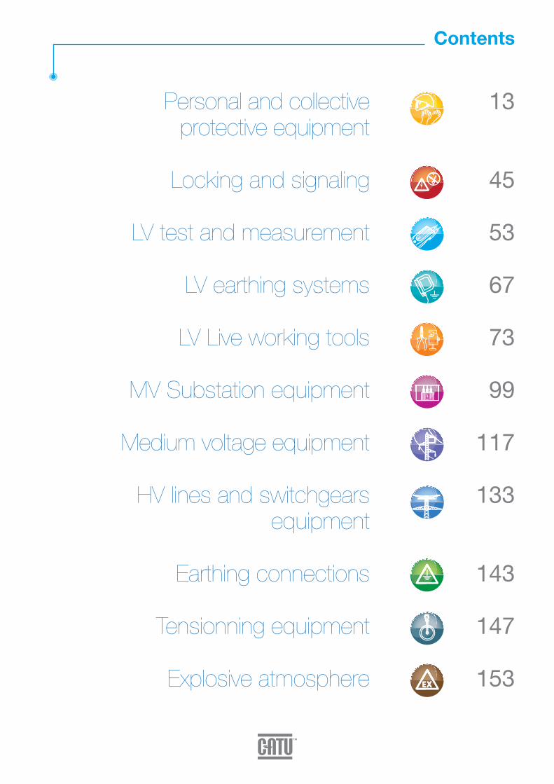
Personal and collective protective equipment
Locking and signaling
LV test and measurement
LV earthing systems
LV Live working tools
MV Substation equipment
Medium voltage equipment
HV lines and switchgears equipment
Earthing connections
Tensionning equipment
Explosive atmosphere
13
45
53
67
73
99
117
133
143
147
153
Contents
4
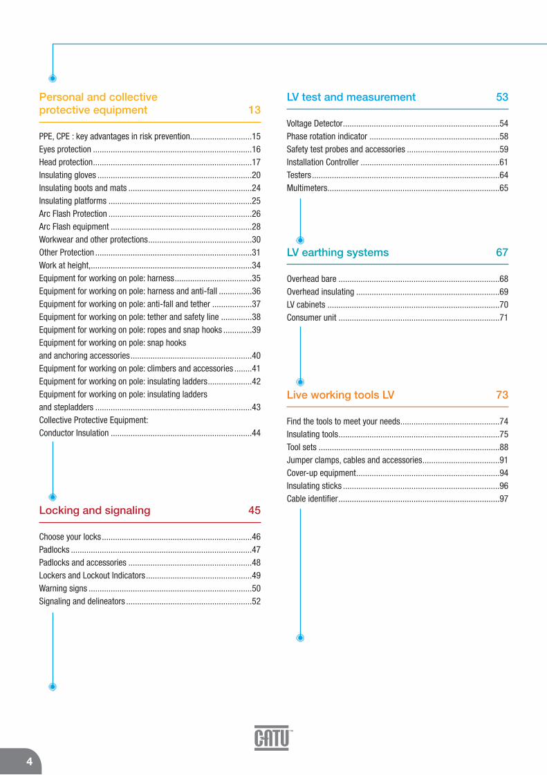
Personal and collective protective equipment 13
PPE, CPE : key advantages in risk prevention............................15Eyes protection ........................................................................16Head protection........................................................................17Insulating gloves ......................................................................20Insulating boots and mats ........................................................24Insulating platforms .................................................................25Arc Flash Protection .................................................................26Arc Flash equipment ................................................................28Workwear and other protections...............................................30Other Protection .......................................................................31Work at height,.........................................................................34Equipment for working on pole: harness...................................35Equipment for working on pole: harness and anti-fall ...............36Equipment for working on pole: anti-fall and tether ..................37Equipment for working on pole: tether and safety line ..............38Equipment for working on pole: ropes and snap hooks .............39Equipment for working on pole: snap hooks and anchoring accessories.......................................................40Equipment for working on pole: climbers and accessories ........41Equipment for working on pole: insulating ladders....................42Equipment for working on pole: insulating ladders and stepladders .......................................................................43Collective Protective Equipment: Conductor Insulation ................................................................44
Locking and signaling 45
Choose your locks....................................................................46Padlocks ..................................................................................47Padlocks and accessories ........................................................48Lockers and Lockout Indicators................................................49Warning signs ..........................................................................50Signaling and delineators .........................................................52
LV test and measurement 53
Voltage Detector.......................................................................54Phase rotation indicator ...........................................................58Safety test probes and accessories ..........................................59Installation Controller ...............................................................61Testers .....................................................................................64Multimeters..............................................................................65
LV earthing systems 67
Overhead bare .........................................................................68Overhead insulating .................................................................69LV cabinets ..............................................................................70Consumer unit .........................................................................71
Live working tools LV 73
Find the tools to meet your needs.............................................74Insulating tools.........................................................................75Tool sets ..................................................................................88Jumper clamps, cables and accessories...................................91Cover-up equipment.................................................................94Insulating sticks .......................................................................96Cable identifier.........................................................................97
5
General products index
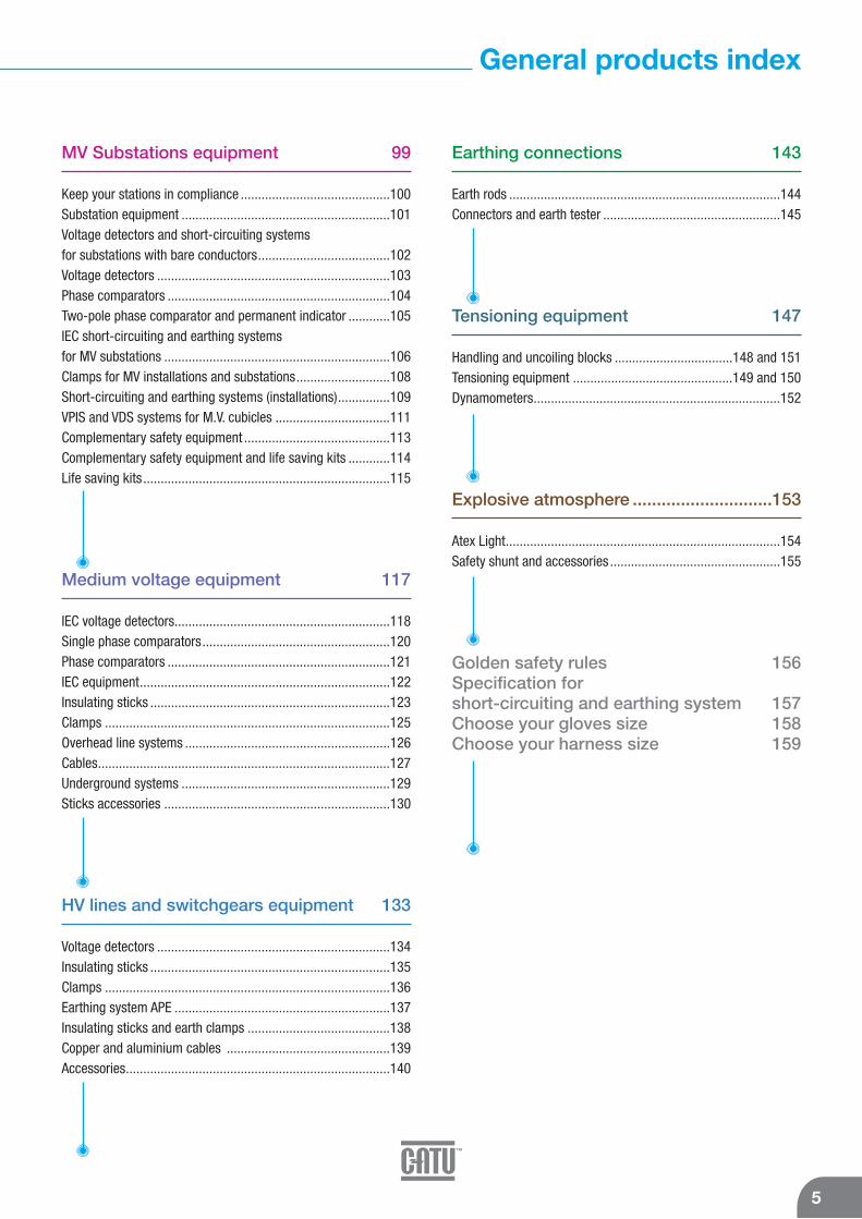
MV Substations equipment 99
Keep your stations in compliance ...........................................100Substation equipment ............................................................101Voltage detectors and short-circuiting systems for substations with bare conductors......................................102Voltage detectors ...................................................................103Phase comparators ................................................................104Two-pole phase comparator and permanent indicator ............105IEC short-circuiting and earthing systems for MV substations .................................................................106Clamps for MV installations and substations...........................108Short-circuiting and earthing systems (installations)...............109VPIS and VDS systems for M.V. cubicles .................................111Complementary safety equipment ..........................................113Complementary safety equipment and life saving kits ............114Life saving kits.......................................................................115
Medium voltage equipment 117
IEC voltage detectors..............................................................118Single phase comparators......................................................120Phase comparators ................................................................121IEC equipment........................................................................122Insulating sticks .....................................................................123Clamps ..................................................................................125Overhead line systems ...........................................................126Cables....................................................................................127Underground systems ............................................................129Sticks accessories .................................................................130
HV lines and switchgears equipment 133
Voltage detectors ...................................................................134Insulating sticks .....................................................................135Clamps ..................................................................................136Earthing system APE ..............................................................137Insulating sticks and earth clamps .........................................138Copper and aluminium cables ...............................................139Accessories............................................................................140
Earthing connections 143
Earth rods ..............................................................................144Connectors and earth tester ...................................................145
Tensioning equipment 147
Handling and uncoiling blocks ..................................148 and 151Tensioning equipment ..............................................149 and 150Dynamometers.......................................................................152
Explosive atmosphere .............................153
Atex Light...............................................................................154Safety shunt and accessories .................................................155
Golden safety rules 156Specification for short-circuiting and earthing system 157Choose your gloves size 158Choose your harness size 159

J
HA
B
C
D
E
F
GH
I
6
ABS helmet ................................................17Ac voltage detector for outdoor/indoor use134Access points ...........................................109Accessories (measurement kit) .................145Adhesive tapes ...........................................44Adjustable access points ..........................140Adjustable spanners ...................................83Adjustment “Come-along”........................149Aluminium cables..............................128/140Anti-fall device with automatic release strap ..............................................37Anti-fall grip ...............................................36Aperture Housing......................................113"Arc flash" face shield kit ..........................28"Arc flash" Gloves .................................22/27"Arc flash" jacket and protective coverall kits ...............................................28"Arc flash" High-Visibility Parka..................27"Arc flash" protective kits (25, 40, 55, 65 or 100 cal/cm2) ...................29Automatic come-along..............................149
Bag for insulator cover................................94Bag tool bag to order separately .................89Bags for insulating mats .............................25Bent snipe nose plier ..................................75Bent snipe nose pliers ................................79Blanket clamp .......................................44/95
Cable cutter......................................76/80/81Cable Identifier ...........................................97Cable spike equipment .............................129Cable testing stick ....................................129Carrying bag...............................................23Chain delineators........................................52Clamp dispender heads ............................125Clamps for installation on bare conductors108Cleaning brushes......................................131Cold Protection Kit and Cap ........................32Combination wrenches ...............................83Come-along..............................................149Compact carrying KIT ...............................114Complete intervention kit.......................77/87Composite gloves .......................................22Conductor insulating end – cap ..................94Connection adaptors for insulating sticks..130Connectors ...............................................145Constraint tie ..............................................40Contact probes for L.V. tester ......................60Copper cables ...................................127/139Copper/steel (350 μ coating) earth rods ....144Cranked ring wrenches...............................84
Delineators .................................................52Differential Controllers ................................61Digital clamp multimeter.............................65Digital multimeter .......................................65Double lanyard ...........................................38Double safety descent device .....................39Double tether rope with energy absorber ....38Dust-proof equipment.................................30Dynamometer for Insulating Conductor .....152
Earplugs .....................................................31Earth clamp.........................106/108/125/138Earth rod ..................................................125Earthing clip .............................................145Earthing coil .............................................157Earthing equipment ....................................69Earthing equipment for overhead lines systems......................................................68Earthing kit support ..................................140Earthing system with clamp interlocking...137Electrician coverall .....................................30End cutting pliers........................................80Equipotential Lines ...................................139
Face shield............................................17-16Fall arrester retractable type .......................37Fixed length sticks....................................123Fixing tools for warning signs .....................52Flat blade screwdrivers .........................75/78Flat nose plier........................................76/79Flexible - type conductor cover ...................94Folding stepladder with railing ....................43Forged steel climbers for round wooden poles .............................................41Frontal ratchet cable cutter.........................81Full body fall arrest harness........................35Fuse puller ...............................................131
Grounding and continuity measurement device ........................................................62Grounding flags ..........................................51Guying equipment ....................................151
Hacksaw ....................................................82Hand stick ..................................................60Handle for 10 and 30 padlocks ...................48Handle with 6 padlocks ..............................48Helmet with built-in face shield ..................18Hexagonal spanners with T handle..............84High performance noise-reduction helmet ..31Hoist ratchet.............................................151
Hook stick ..................................................96HV and EHV clamps manœuverable by insulating stick.....................................136
IEC electronic Voltage Detectors, “Compactserie” for indoor and outdoor use..............119IEC Insulating stick for Voltage Detector ....102IEC short-circuiting and earthing systems(three-phase crossarm networks) .............122IEC Voltage detector..................................102Infrared thermometer .................................64Installation on bare conductors .................107Installation on permanent fixed points.......106Insulating blanket .....................................129Insulating boots ..........................................24Insulating cable cutter ..............................115Insulating flexible cover .........................44/95Insulating flexible cover with Velcro™ tape.................................44/95Insulating gloves "Arc flash".......................22Insulating gloves for "Arc flash" protection .27Insulating ladders .......................................42Insulating mats...........................................24Insulating platform (outdoor model) ............25Insulating platforms (indoor models) ...........25Insulating Pole bags..................................132Insulating running-block ...........................148Insulating stepladders.................................43Insulating sticks for manœuvring detectors & short-circuiting and earthing systems....135Insulating sticks for short circuiting and earthing systems ......................................138Insulating sticks for short-circuiting and earthing systems ......................................124Insulating sticks for substation use ...........110Insulating tape.......................................44/95Insulating tool kits ......................................87Insulating torque wrench 3/8” ....................86Insulation controller ....................................63Insulator cover............................................94Integrated voltage detecting system (V.D.S) ......................................................111Integrated voltage presence indicating system (V.P.I.S) .........................................111Interface for integrated voltage detecting system (V.D.S) ..........................................112Intervention kit ......................................77/87Intervention kit for electricians....................90Intervention kits Substation equipment .....101Intrinsically safe ATEX LED's Headlamp.....154
Jumper cable with insulating jumper clamps .......................................................92Jumper cables............................................92

JL
M
NO
R
S
P
S
T
U
V
W
7
General products index
Jumper cables realisation specially manufactured items .................................128Jumper connecting box with fuse ...............93
Lanyard ......................................................39Lead set for checks on L.V distribution board..........................................................60LED’s headlamp .........................................19LED’s headlamp (4 LED’s)...........................19Life saving kits for M.V. substations ..........115Long nose pliers with side cutter ................79Lockers ......................................................49Low voltage complete set. Complete equipment for live line (LV) interventions.....89Lowlock system..........................................69
Manœuvring and rescue stick...................113Manœuvring hook.....................................131Mechanical adjusters ...............................150Mechanical climbers for rectangular shapedconcrete poles............................................41Mechanical climbers for round and hexagonalconcrete poles............................................41Mini jumper clamps fully insulating for switchboard use....................................91Mittens .......................................................23Mobile safety line .......................................38Multi-pockets electrician bag......................25Multiple Locker...........................................49Multiple locking apparatus..........................48
Noise-reduction cover for helmet................31
Open end spanners.....................................84Opening block ..........................................148Operating Testers......................................104Overglasses................................................16Overgloves .................................................23
Padlocks.....................................................47Parallel jaws “Come-along”......................150Permanent luminous indicator for indoor use ...........................................105Phase rotation indicator ..............................58Phase tester insulated screwdriver .............64Pliers ..........................................................87Pliers kit .....................................................77Plug plier for preinsulating pin terminals.....79Pneumatic glove tester ...............................22Poles skirts...............................................110Polycarbonate helmet .................................17
PPE-CPE Accessories..................................18Pro electric full body fall arrest harness ......35Pulling Cable Clip......................................149
Ratchet cable cutters..................................81Rescue hook.............................................114Reversible hexagonal ratchet handles.........83Right angle hexagonal key wrenches ..........83Rope operated clamp................................141Round nose plier ...................................76/79Rubber gloves box ......................................22
Safety adhesive tape ..................................52Safety boots ...............................................32Safety boundary post..................................52Safety glasses ............................................16Safety lamps ............................................113Safety rope with wear tell tales...................39Safety Shoes ..............................................32Safety test probe for voltage detector use only......................................................59Scissors......................................................86Screwdrivers PHILLIPS ...............................78Screwdrivers POZIDRIV .........................75/78Screwdrivers kit .........................................77Self adhesive warning signs .......................51Separable voltage detecting system (V.D.S) ..........................................112Set of sticks..............................................135Short circuiting device for LV cabinet ..........70Short length stick .....................................110Short-circuiting and earthing systems.......126Short-circuiting and earthing systems carrying bags ...........................................142Short-circuiting equipment .........................71Short-circuiting systems.............................68Shunt Telescopic probe...............................93Side cutters ...........................................76/80Single pole phase comparator for indoor and outdoor use .......................................120Snap hook with double safety latch ............39Snap hook with stick adapter......................40Snap hooks (aluminium alloy) .....................40Snap hooks (stainless steel)........................40Socket 3/8” - 6 sided male hex Key ...........86Sockets 3/8” Long series............................86Sockets 3/8” U.S Standard .........................86Sockets wrenches sets ...............................85Soft case ....................................................88Sound phase comparator..........................111Spool with earthing connection.................125Stainless steel earth rods..........................144Standard electronic voltage detector for indoor and outdoor use........................119
Standard extension ladders ........................43Standard sticks.........................................110Sticks with rain skirts ...............................124Storage bag ...............................................60Stripping knifes ..........................................82Stripping plier for LV cables ........................82Substation signs .........................................50
Tap off box .................................................93Telescopic stick for voltage detector .........123Tensioning block.......................................150Tether rope with a tension device. ..............37Threaded adapter .......................................93Tool bag .....................................................88Tool bag for safety harness.........................41Torchs for explosives atmospheres (ATEX)154Trimmer and prunning saw.......................131Two-pole phase comparator for indoor and outdoor use ................................104/105
Uncoiling block .........................................148Undergloves ...............................................23Undergloves Nomex III ®.......................23/27Universal hand stick ...................................96Universal pliers......................................75/78
Voltage Detectors and Testers................54/56Voltage detector with leds for indoor use (Compact serie) without batteries .............103Voltage detector with leds for indoor use without batteries.......................................103Voltage detectors and indicators ...............112Voltage take-off punch................................59Voltage tester for M.V. separable connectors ...............................................112
Wall mounted supports......................114/123Warning flags .............................................50Warning signs.............................................50Water pump plier...................................76/80Winches TIRFOR and JOCKEY ...................150Wire Gun Tester ........................................141Wire stripping plier ................................76/82Wire-cutter stick.........................................96Wireless phase comparator ......................121Work Gloves ...............................................31Working on pole kits ...................................36

References PagesReferences PagesReferences PagesReferences PagesA-76230
AC-21
AC-44
AD-01
AL-200
AL-201-C/1
AL-201/1
AL-202
AL-203
AL-205
AL-205/5
AL-207/10
AL-207/30
AL-230-(**)-EX
AL-230-S-(**)-EX
AL-230-S-Z-EX
AL-230-Z-EX
AL-236-00-EX
AL-236-111-EX
AL-236-222-EX
AL-236-S-00-EX
AL-236-S-111-EX
AL-236-S-222-EX
AL-240-(**)-EX
AL-240-B-(**)-EX
AL-240-B-00-EX
AL-240-B-Z-EX
AL-240-BL-(**)-EX
AL-240-BL-00-EX
AL-240-BL-Z-EX
AL-240-J-(**)-EX
AL-240-J-00-EX
AL-240-J-Z-EX
AL-240-S-(**)-EX
AL-240-S-B-(**)-EX
AL-240-S-B-00-EX
AL-240-S-BL-(**)-EX
AL-240-S-BL-00-EX
AL-240-S-J-(**)-EX
AL-240-S-J-00-EX
AL-240-S-V-(**)-EX
AL-240-S-V-00-EX
AL-240-S-Z-EX
AL-240-V-(**)-EX
AL-240-V-00-EX
AL-240-V-Z-EX
AL-240-Z-EX
AL-31
AL-31/05
AL-31/25
AL-316
AL-318
AL-32/05
AL-53
AL-58
AL-60
AL-62-A
AL-63-A
AL-65-A
AM-20-GB
AM-20-RM
AM-215-RM
AM-282/2-RM
AM-32/3
47
52
52
52
48
49
49
48
48
49
49
48
48
47
47
47
47
48
48
48
48
48
48
47
47
47
47
47
47
47
47
47
47
47
47
47
47
47
47
47
47
47
47
47
47
47
47
52
52
52
52
52
52
50
51
51
52
52
52
50
50
50
50
50
AM-33/3
AM-34/2
AM-344
AM-344-GB
AM-344/05
AM-345-GB
AM-41/1
AM-41/2
AM-467-GB
AM-49/1
AM-49/2
AM-61-GB
AM-61-RM
AM-7002
AP-499/1
AP-510-BT-GB
AP-510-GB
AP-951/2
AT-41/025
AT-41/05
AT-41/1
AT-49/025
AT-49/05
AT-49/1
AT-50/025
AT-50/053
AT-50/1
AT-5005
AT-51/025
AT-51/05
AT-51/1
AT-52/05
AT-52/1
AT-53/05
AT-53/1
AT-54/05
AT-54/1
AT-55/05
AT-55/1
AT-56/05
AT-56/1
AT-57/05
AT-57/1
AT-58/05
AT-58/1
AT-59/05
AT-59/1
AT-60/05
AT-60/1
AT-61/05
AT-61/1
AT-62/05
AT-62/1
AT-63/05
AT-63/1
AT-64/1
AT-66/1
C-92-20
CC-151-K
CC-245-150
CC-245-150/420-(*)
CC-245-225/420-(*)
CC-245-225/550-(*)
CC-245-315/765-1-(*)
50
50
50
50
50
50
50
50
50
50
50
50
50
50
50
50
50
50
51
51
51
51
51
51
51
51
51
52
51
51
51
51
51
51
51
51
51
51
51
51
51
51
51
51
51
51
51
51
51
51
51
51
51
51
51
51
51
104
112
134
134
134
134
134
CC-245-60/150-(*)
CC-245-63/150-(*)
CC-245-63/90-(*)
CC-245-90/225-(*)
CC-365-10/30-(*)
CC-365-101
CC-365-3/10-(*)
CC-45-K
CC-875-10/30-(*)
CC-875-10/36-(*)
CC-875-11/33-(*)
CC-875-5,5/20-(*)
CC-92-492
CD-122
CD-124
CE-3-24-C
CE-3-72-(*)
CE-3-90-(*)
CE-4-21-(*)
CE-4-21-C
CE-5-90-C
CE-5-90-K
CE-75-(*)
CF-5-110-(*)
CF-5-170-(*)
CF-5-40-(*)
CF-5-90-(*)
CF-5-90-(*)
CF-5-90-(*)
CG-02-(*)
CG-05-(*)
CG-10-(*)
CG-11-(*)
CG-117
CG-12-(*)
CG-15-(*)
CG-16-(**)
CG-20-(*)
CG-22-(**)
CG-30-(*)
CG-35/2
CG-36/1
CG-36/2
CG-37
CG-40-(*)
CG-65-CAL
CG-80-(*)
CG-81
CG-96-(*)
CG-97-C
CG-98-(*)
CG-99-(*)
CGL-20-(*)
CGL-30-(*)
CI-06-D
CI-08
CI-10-D
CI-12-D
CI-70
CL-1-06
CL-12-12/36*
CL-12-4/12*
CL-2-10/30-2
CL-2-5/36-2
134
134
134
134
119
119
119
112
118
102 / 118
102 / 118
118
119
113
113
110
110
110
110 / 123 / 160
102
40
40
110 / 123 / 160
123 / 160
123 / 160
110 / 123 / 124
110 / 124
123
124
22
21
21
27
22
22
21
22
21
22
21
22
23
23
27
21
27
23
23
31
31
21 / 23
21 / 23
22
22
107 / 114 / 123
114 / 123
106 / 114 / 123
123 / 160
113
104
121
121
103
103
CL-4-10-30-2
CL-4-10-30-M
CL-40010
CL-495-3
CL-497-00
CL-498-00
CL-499/101
CL-5-03
CL-5-36
CL-7-06/18-(*)
CL-7-10/30-(*)
CL-7-10/30-1-(*)
CL-7-12/36-(*)
CL-8-05
CL-8-36
CL-8-36/1
CM-02-(*)
CM-03-K
CM-04-K
CM-1-10
CM-1-15
CM-1-20
CM-225
CM-3-03
CM-3-04
CM-3-05
CM-3-06
CM-3900-J
CM-4115-(*)
CM-4120-(*)
CM-4125-(*)
CM-4130-(*)
CM-4220-(*)
CM-4230-(*)
CM-4240-(*)
CM-4345-(*)
CM-4360-(*)
CM-4400-J
CM-4410
CM-4410-(*)
CM-4410-I
CM-4415
CM-4415-(*)
CM-4415-I
CM-4420
CM-4420-(*)
CM-4420-I
CM-4425
CM-4425-(*)
CM-4425-I
CM-45
CM-4610
CM-4610-(*)
CM-4610-I
CM-4615
CM-4615-(*)
CM-4615-I
CM-4620
CM-4620-(*)
CM-4620-I
CM-4625
CM-4625-(*)
CM-4625-I
CM-6-15
103
103
105
111
111
112
112
105
105
120
120
120
120
104
104
104
131
131
131
132
132
132
113
132
132
132
132
135
135
135
135
135
135
135
135
135
135
124
124
124
124
124
124
124
124
124
124
124
124
124
113
135
135
135
135
135
135
135
135
135
135
135
135
138
8
References PagesReferences PagesReferences PagesReferences PagesCM-6-20
CM-6-25
CM-6-30
CM-7-10-A
CM-90
CS-01-C
CS-225
CS-45
CS-90
CT-7-25/1
CT-7-40/1
CT-7-63
CT-9-25
CT-9-45
CT-9-63
CX-34211
CX-35811
CX-45211
CX-45411
CX-45511
CZ-53-MR
CZ-53-R
CZ-53-R/2
CZ-53MR/2
CZ-54-R
CZ-54-RM
CZ-55-R
CZ-55-RM
CZ-60
DT-170
DT-300
DT-500
ENR-15-ATEX
KIT-01
KIT-02
KIT-03
KIT-04
KIT-05
KIT-07
KIT-10
KIT-23
KIT-24
KIT-25
KIT-27
KIT-ARC-08-C-(*)
KIT-ARC-10-C-(*)
KIT-ARC-10-J-(*)
KIT-ARC-10-JP-(*)
KIT-ARC-100-B-(*)
KIT-ARC-25-B-(*)
KIT-ARC-40-B-(*)
KIT-ARC-55-B-(*)
KIT-ARC-65-B-(*)
KIT-HAUT-01-(*)
KIT-HAUT-02-(*)
KIT-HAUT-03-(*)
KIT-HAUT-04-(*)
KIT-HAUT-05-(*)
KIT-HAUT-06-(*)
M-24-10
M-24-120
M-24-120-S
M-24-150
M-24-150-S
138
138
138
110 / 123 / 160
113
114
113
113
113
25
25
25
25
25
25
59
59
59
59
59
114
114
114
114
115
115
115
115
115
61
62
63
155
101
101
87
87
87
87
101
77
77
77
77
28
28
28
28
29
29
29
29
29
36
36
36
36
36
36
127
127 / 139
128 / 139
129 / 139
130 / 139
M-24-16
M-24-16-S
M-24-25
M-24-25-S
M-24-30
M-24-35
M-24-35-S
M-24-40
M-24-40-S
M-24-50
M-24-50-S
M-24-70
M-24-70-S
M-24-75
M-24-95
M-24-95-S
M-28-120
M-28-150
M-28-50
M-28-70
M-52-91/92
M-78665
M-87-153
M-87-295
M-87-53
M-87290
M-87292
M-87303
M-87369
M-87370
M-87384
M-87384
M-87386
M-87386
M-87396
M-881622
M-881635
M-881836
M-881837
M-881838
M-881954
M-882082
M-92-28
M-921647
M-951143
M-951981
M-952206
M-952271
M-952325
M-95626/4
M-95627/4
MC-116
MC-120/100
MC-120/15
MC-120/50
MC-121
MC-122
MC-123
MC-124
MC-126
MC-126/1
MC-141
MC-142
MC-1421
127
127
127
127
127
127
127
127
127
127
127
127 / 139
127 / 139
127 / 139
127 / 139
127 / 139
128 / 140
128 / 140
128
128 / 140
96
106
142
142
142
58 / 60
60 / 61 / 63
88
55 / 57
88
18 / 89
89
25 / 89
89
60
18
17 / 18
18
18
18
61
27
131
62
60
63
17
60 / 61
55 / 57
71
71
93
92
92
92
92
92
92
92
93
93
91
91
97
MC-143
MC-144
MC-145
MC-146
MC-147
MC-147/1
MC-148
MC-148/1
MC-149
MC-150
MC-153/05
MC-153/10
MC-153/30
MC-153/60
MC-155/05
MC-155/10
MC-155/20
MC-155/30
MC-155/60
MC-155/80
MC-156
MC-156/1
MC-161
MC-181
MC-182
MC-183
MC-237-D
MC-244/1
MC-245/1
MC-296-00/08
MC-296-115/08
MC-296-115/12
MC-296-160/12
MC-296-P
MC-296/320
MC-296/440
MC-296/440M12
MD-02
MD-10-C
MD-12-C
MD-14-C
MD-40-B
MD-42-B
MF-60
MF-61
MF-62
MF-63
MF-66
MG-116-S
MG-117-S
MG-125-K
MG-130
MG-131
MK-08
MK-100
MK-15
MK-20
MK-40
MK-60
ML-05/10
ML-08/20
ML-16/20
ML-32/20
MO-052
91
91
91
91
91
91
91
91
91
93
92
92
92
92
92
92
92
92
92
92
93
93
71
93
93
93
93
70
70
71
71
71
71
71
71
71
71
39
131
131
131
131
131
141
141
141
141
141
96
96
96
96
96
149
150
149
149
150
150
150
150
150
150
39
MO-11000
MO-11001
MO-11003
MO-11010
MO-11011
MO-131/1
MO-131/2
MO-132
MO-151
MO-151/100
MO-152
MO-155
MO-156
MO-157
MO-158
MO-16-A
MO-17-01
MO-17-02
MO-17-03
MO-17-04
MO-17-A
MO-182/1-B
MO-182/1-J
MO-182/1-R
MO-183-BL
MO-183-RL
MO-184
MO-185-B
MO-185-BL
MO-185-BLM
MO-185-J
MO-185-R
MO-186
MO-24
MO-25
MO-26
MO-308
MO-32/3
MO-3260/05
MO-3260/10
MO-331/04-B
MO-331/06-A
MO-331/08-B
MO-331/09-A
MO-331/10-B
MO-331/12-A
MO-331/13-P
MO-331/16-B
MO-331/22-P
MO-331/26-B
MO-331/38-P
MO-332/13-E
MO-332/14-D
MO-332/18-E
MO-337/06
MO-339/02
MO-339/03
MO-339/09-D
MO-34
MO-343
MO-344
MO-35
MO-36
MO-371
16
16
16
16
16
30
30
30
31
31
31
31
31
32
32
41
41
41
41
41
41
17
17
17
17
17
16
18
18
18
18
18
17
41
41
41
148
41
152
152
150
150
150
150
150
150
149
150
149
150
149
149
149
149
149
149
149
149
88 / 89
150
150
41
88
148
9
General references index

References PagesReferences PagesReferences PagesReferences PagesMO-371/01
MO-371/100
MO-375/150
MO-375/250
MO-375/300
MO-375/400
MO-38510
MO-43200
MO-43201
MO-43202
MO-43203
MO-510-03-EX
MO-52-L
MO-52-P
MO-52020
MO-52021
MO-52031
MO-52033
MO-52034
MO-53
MO-53002
MO-53010
MO-54
MO-54000
MO-54002
MO-54004
MO-54005-C
MO-54005-K
MO-54010
MO-55/1
MO-56009
MO-56010
MO-563-(*)
MO-565-(*)
MO-591000
MO-591002
MO-61
MO-61001
MO-61002
MO-64502
MO-650-D
MO-652-D
MO-65202
MO-65203
MO-65204
MO-65205
MO-65206
MO-65207
MO-65209
MO-65211
MO-65222
MO-65230
MO-65232
MO-65234
MO-65236
MO-65238
MO-65240
MO-65242
MO-65244
MO-65246
MO-65248
MO-653-D
MO-66001
MO-66002
MO-66003
MO-66005
MO-66102
MO-66105
MO-66202
MO-66300
MO-66302
MO-66402
MO-66404
MO-66502
MO-67101
MO-67102
MO-67103
MO-67302
MO-67304
MO-67305
MO-67306
MO-67401
MO-67402
MO-67404
MO-67500
MO-67501
MO-67502
MO-67599
MO-67600
MO-67601
MO-67611
MO-68/10
MO-68/15
MO-68008
MO-68008/19
MO-68009
MO-68010
MO-68011
MO-68012
MO-68013
MO-68014
MO-68015
MO-68016
MO-68017
MO-68018
MO-68019
MO-68020
MO-68021
MO-68022
MO-68023
MO-68024
MO-68025
MO-68026
MO-68027
MO-68028
MO-68029
MO-68030
MO-68032
MO-68107
MO-68108
MO-68109
MO-68110
MO-68111
MO-68112
MO-68113
MO-68114
MO-68115
MO-68116
MO-68117
MO-68118
MO-68119
MO-68120
MO-68121
MO-68122
MO-68123
MO-68124
MO-68125
MO-68126
MO-68127
MO-68128
MO-68129
MO-68130
MO-68132
MO-68610
MO-68613
MO-68614
MO-68701
MO-68702
MO-68703
MO-68704
MO-69002
MO-69003
MO-69004
MO-69005
MO-69050
MO-69210
MO-69213
MO-69216
MO-69217
MO-69218
MO-69219
MO-69306
MO-69307
MO-69308
MO-69308/23
MO-69309
MO-69310
MO-693100
MO-69311
MO-69312
MO-69313
MO-69314
MO-69315
MO-69316
MO-69317
MO-69318
MO-69319
MO-69321
MO-69322
MO-69323
MO-69393
MO-69394
MO-69395
MO-69396
MO-69397
MO-69398
MO-69408
MO-69408/23
MO-69410
MO-69411
MO-69412
MO-69413
10
MO-69414
MO-69415
MO-69416
MO-69417
MO-69418
MO-69419
MO-69420
MO-69421
MO-69422
MO-69423
MO-69424
MO-69430
MO-69513
MO-69514
MO-69523
MO-69524
MO-69533
MO-69534
MO-69542
MO-69543
MO-69544
MO-69610
MO-69612
MO-69613
MO-69614
MO-69616
MO-69617
MO-69618
MO-69619
MO-69621
MO-69622
MO-69624
MO-69735
MO-69736
MO-69737
MO-69738
MO-69739
MO-69740
MO-69741
MO-69742
MO-69903
MO-69904
MO-69905
MO-69906
MO-69908
MO-69910
MO-69912
MO-71
MO-72003
MO-72004
MO-72005
MO-72006
MO-72007
MO-72009
MO-72040
MO-72042
MO-72044
MO-72046
MO-72100
MO-72102
MO-72122
MO-72132
MO-72142
MO-72155
85
85
85
85
85
85
85
85
85
85
85
85
85
85
85
85
85
85
85
85
85
86
86
86
86
86
86
86
86
86
86
86
86
86
86
86
86
86
86
86
83
83
83
83
83
83
83
35
75
75
75
75
75
75
75
75
75
75
86
75
76
76
75
76
148
148
148
148
148
148
90
151
151
151
151
89
37
37
38
38
40
40
40
39
38
38
40
40
39
40
40
40
38
40
37
37
35
35
37
37
37
82
82
82
78
78
78
78
78
78
78
78
78
78
64
78
78
78
78
78
78
78
78
78
78
78
78
78
78
78
79
79
79
79
79
79
79
80
80
80
80
82
82
82
82
80
80
80
80
81
81
81
81
81
81
36
36
84
84
84
84
84
84
84
84
84
84
84
84
84
84
84
84
84
84
84
84
84
84
84
84
84
84
84
84
84
84
84
84
84
84
84
84
84
84
84
84
84
84
84
84
84
84
84
84
84
84
84
84
84
83
83
83
83
83
83
83
83
86
83
83
83
83
83
83
85
85
85
85
85
85
86
85
85
85
85
85
85
85
85
85
85
85
85
86
86
86
86
86
86
85
85
85
85
85
85

References PagesReferences PagesReferences Pages References Pages
11
General references index
MO-72162
MO-72172
MO-72200
MP-01
MP-01
MP-02
MP-100/03-10
MP-100/03-5
MP-100/05-10
MP-100/05-5
MP-100/10-10
MP-100/10-5
MP-123
MP-123/1
MP-123/2
MP-19-(*)
MP-19-LOT
MP-211
MP-212
MP-213
MP-213/EXT
MP-213/LAM
MP-22
MP-23
MP-26-A
MP-26-B
MP-26-C
MP-26-D
MP-26-E
MP-31
MP-311
MP-315
MP-32/10
MP-32/15
MP-33
MP-35
MP-35/12
MP-37
MP-39
MP-40
MP-4110
MP-41530
MP-42/11
MP-42/16
MP-42/66
MP-50
MP-506/2
MP-508/2
MP-509/2
MP-510/2
MP-514/2
MP-515/2R
MP-59
MP-60/03-10
MP-60/03-5
MP-60/05-10
MP-60/05-5
MP-602-D
MP-603-D
MP-604-D
MP-605-D
MP-607/2-I
MP-607/3-I
MP-608/2-I
76
76
76
25
89
25
24
24
24
24
24
24
44 / 95
44 / 95
44 / 95
44
44
129
129
129
129
129
94
94
94
94
94
94
94
94
151
151
94
94
94
44 / 95
44 / 95
44 / 95
44 / 95
44 / 95
44 / 95
44 / 95
24
24
24
94
42
42
42
42
42
42
94
24
24
24
24
42
42
42
42
43
43
43
MP-608/3-I
MP-609/2-I
MP-634/2-D
MP-700-1
MP-700-2
MP-700-3
MP-700-4
MP-700-5
MP-700-6
MS-124
MS-125
MS-126
MS-129
MS-130
MS-131/1
MS-152+
MS-62
MS-63
MS-8013
MS-8014
MS-917-EX
MS-917/2-EX
MS-920-EX
MT-1910
MT-1911
MT-1911-E
MT-1920
MT-1921
MT-1921-E
MT-1951/10
MT-1951/12
MT-205
MT-206
MT-207
MT-222
MT-223
MT-242
MT-244
MT-245
MT-249
MT-2950/35
MT-2951
MT-2951/1
MT-2951/2
MT-3950/35
MT-3951
MT-3951/1
MT-3952
MT-3952/1
MT-40
MT-404
MT-405
MT-406
MT-407
MT-508/36
MT-508/46
MT-5805
MT-615/1-7,5
MT-615/2-7,5
MT-630-C
MT-630-K
MT-630-S
MT-633-C
MT-633-K
43
43
42
43
43
43
43
43
43
19
19
154
154
154
154
58
59
59
60
60
55
55
57
106
106
106
106
106
106
109
109
69
69
69
69
69
68
68
68
68
109
109
109
109
109
109
109
109
109
128
68
68
68
68
126
126
107
69
69
125
125
125
125
125
MT-633-S
MT-634-C/K
MT-634/1-C/K/S
MT-635/1-C/K/S
MT-640-S
MT-650
MT-650
MT-6613
MT-6613/1
MT-70/1
MT-701/1
MT-731-(*)
MT-732-(*)
MT-734-(*)
MT-735-(*)
MT-737-H
MT-790
MT-792
MT-797
MT-811-C
MT-812-C
MT-813-C
MT-814/2
MT-814/3
MT-815-C
MT-815-E
MT-815-S
MT-815-S1
MT-817-C
MT-834-E
MT-834-H
MT-834-T
MT-835-E
MT-835-H
MT-835-T
MT-837-E
MT-837-H
MT-837-T
MT-840
MT-840/1
MT-8408
MT-841
MT-843
MT-843-P
MT-847
MT-852
MT-853
MT-890
MT-891
MT-893
MT-895
MT-920-E
MT-925-E
MT-934
MT-935
MT-951/1
MT-951/2
MT-951/3
MT-952/1
MT-952/2
MT-952/3
MT-953/08
MT-953/12
MT-955/08
125
125
125
125
125
69
125
122
122
128
141
136
136
136
136
136
140
140
140
108
108
108
108
108
108
108
108
108
108
137
137
137
137
137
137
137
137
137
108
108 / 125
107
108
125 / 138
138
138
138
138
106 / 107
106 / 107
106 / 107
106 / 107 / 140
109
109
137
137
109
109
109
109
109
109
109
109
109
MT-955/12
MT-956
MT-9801
MT641-S
MV-104/(*)
MV-123-(*)
MV-124-(*)
MV-131-(*)
MV-134-(*)
MV-135-(*)
MX-400
MX-400/1
MX-400/6
MX-400/7
MX-404
MX-430-M
MX-433-T
MX-701
MX-702
MX-704
TF-1
TO-2-16
TO-2-19
TO-3-16/19
TO-32/100
TO-8/32
TP-1610-R
TP-1615-R
TP-1620-R
TP-1910-R
TP-1915-R
TP-1920-R
TR-116-10
TR-116-15
TR-119-10
TR-119-15
TR-119-20
TR-1610
TR-1615
TR-1620
TR-1910
TR-1915
TR-1920
TRI-1610
TRI-1615
TS-1601
TS-1901
ZCESSV3502C1240
ZCESSV3503C1240
ZCESSV3504C1240
ZCESSV3505C1240
ZCESSV3506C1240
ZCESSV3507C1240
ZCESSV3510C1240
ZCESSV3512C1240
ZCESSV3515C1240
ZCESSV3550C1240
ZLEQ3735L010
ZLEQ3735L04
ZLEQ3735L06
ZLEQ3735L15
109
109
107
125
30
32
32
32
24
24
97
97
97
97
111
145
145
65
65
64
145
145
145
145
145
145
144
144
144
144
144
144
144
144
144
144
144
144
144
144
144
144
144
144
144
145
145
139
139
139
139
139
139
139
139
139
139
139
139
139
139

IEC Standard
International Electrotechnical Commission is a worldwideorganization for standardization comprising nationalelectro technical committees (NC). The object of the IEC isto promote international cooperation on all questionsconcerning standardization in the electrical fields. Thesestandards have been approved by more than 50 differentcountries including Australia, Canada, China, France,Germany, Japan, Russia, Malaysia, Singapore, Mexico,India, Indonesia, South Africa, New Zealand, USA…
A rapid need to perform electrical operations evolved with the time.
This resulted in regional or national working on specific standards withoutcoordination.
IEC standards were developed according to a consensus procedure and approvedby recognized body. They provide an adequate answer at worldwide level.
The IEC standard presents benefits to all parties involved:
- for the end-users: it is the guarantee of a suitable and internationally recognizedquality equipment,
- for the Testing Laboratories: it determines better standards of testing and controlprocedures for materials,
- for the manufacturers: it helps them to make a better technico-commercial offer.
CATU Designs, tests and manufactures under the IEC requirements.
CATU Is the first manufacturer to provide a full range of products complying withthe IEC standards.
CATU Shows its innovation ability for the welfare of the electrical world.

Eyes protection 16
Head Protection 17
Insulating rubber gloves 20
Insulating boots and mats 24
Insulating platforms 25
"Arc Flash" protection 26
Workwear and other protections 30
Work at height 34
Collective Protective Equipment: conductor insulation 44
Personal and collectiveprotective equipment

14
PPE - CPE
15
PPE, CPE :key advantages in risk prevention.
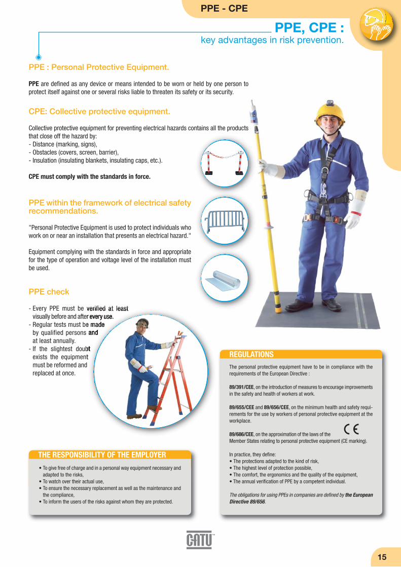
THE RESPONSIBILITY OF THE EMPLOYER
REGULATIONS
• To give free of charge and in a personal way equipment necessary andadapted to the risks,
• To watch over their actual use, • To ensure the necessary replacement as well as the maintenance and
the compliance, • To inform the users of the risks against whom they are protected.
PPE within the framework of electrical safetyrecommendations.
"Personal Protective Equipment is used to protect individuals whowork on or near an installation that presents an electrical hazard."
Equipment complying with the standards in force and appropriatefor the type of operation and voltage level of the installation mustbe used.
PPE check
- Every PPE must be verified at least visually before and after every use.
- Regular tests must be madeby qualified persons andat least annually.
- If the slightest doubtexists the equipmentmust be reformed andreplaced at once.
The personal protective equipment have to be in compliance with therequirements of the European Directive :
89/391/CEE, on the introduction of measures to encourage improvementsin the safety and health of workers at work.
89/655/CEE and 89/656/CEE, on the minimum health and safety requi-rements for the use by workers of personal protective equipment at theworkplace.
89/686/CEE, on the approximation of the laws of theMember States relating to personal protective equipment (CE marking).
In practice, they define: • The protections adapted to the kind of risk,• The highest level of protection possible,• The comfort, the ergonomics and the quality of the equipment,• The annual verification of PPE by a competent individual.
The obligations for using PPEs in companies are defined by the EuropeanDirective 89/656.
PPE : Personal Protective Equipment.
PPE are defined as any device or means intended to be worn or held by one person toprotect itself against one or several risks liable to threaten its safety or its security.
CPE: Collective protective equipment.
Collective protective equipment for preventing electrical hazards contains all the productsthat close off the hazard by:- Distance (marking, signs),- Obstacles (covers, screen, barrier),- Insulation (insulating blankets, insulating caps, etc.).
CPE must comply with the standards in force.

16
Eyes protection
Safety glasses
Protection against UV radiation and ejections ofsolid particles.
Grilamid frame
Tips “Softflex”.
Polycarbonate lensewith a large field ofvision. Anti-scratch,anti-impact and anti-chemical producttreatments.
Caution: Do not use forwelding operations.
Caution: Do not use forwelding operations.
EN 166 / EN 170
Reference
MO-11000
MO-11001
MO-11003 *
Clearlenses
Tintedlenses
Tintedlenses
Delivered in storage bag.* EN 169 - 80 °C - FT HTA N°127.
Characteristics UV protection Resistance
99.5 %< 370 nm
99.5 %< 370 nm
UV/IR protection,
welding filter
Overglasses
Polycarbonate overglasses. Protection against UV radiation and ejections of solid particles.
Reference
MO-11010
MO-11011
Clearlenses
Green tintedlenses
Delivered in storage bag.
Characteristics UV protection Resistance
100 %180 < 400 nm
Level FImpact:
6 mm steelball launched
at 45 m/s 100 %
180 < 400 nm
MO-11000
MO-11003MO-11001
MO-11011
MO-11010
Polycarbonate lensand frame with apanoramic field ofvision.
One piece wraparound protectionthat can be worn over eyeglasses.
EN 166 / EN 170
EN 166 / EN 170
Face shield
Protection against electric short-circuit arcs. Faceshield adjustable on MO-182 helmet.
Reference
MO-184 470 x 200 170100%
Acetate face shield
mm g
Fa ce shield on helmetMO-182/1-B.
mm Dimensions g Weight
Adjustable by rubber band.
Level F
Impact: 6 mm
steel ball launched at
45 m/s
Caution: Do not use forwelding operations.
UV protection
PPE - CPE
17
Head protection
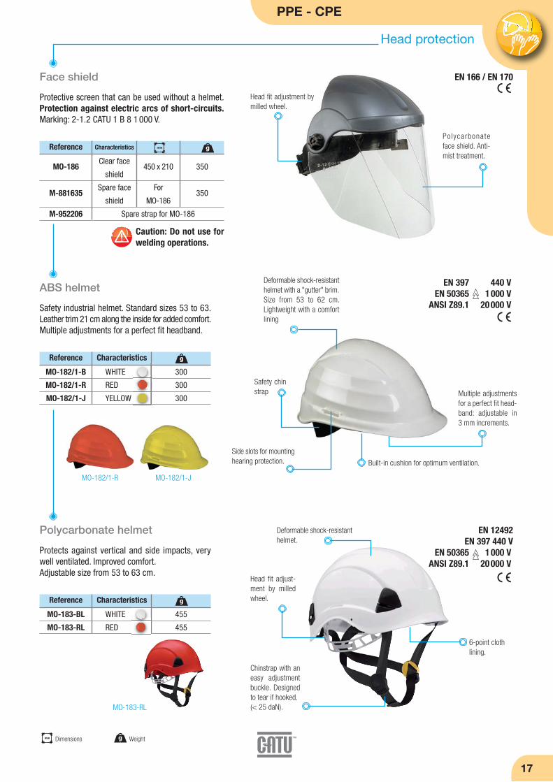
Face shield
Protective screen that can be used without a helmet.Protection against electric arcs of short-circuits.Marking: 2-1.2 CATU 1 B 8 1 000 V.
ABS helmet
Safety industrial helmet. Standard sizes 53 to 63.Leather trim 21 cm along the inside for added comfort.Multiple adjustments for a perfect fit headband.
Polycarbonate helmet
Protects against vertical and side impacts, verywell ventilated. Improved comfort.Adjustable size from 53 to 63 cm.
Reference
MO-186
M-881635
M-952206
Clear face
shield
Spare face
shield
Spare strap for MO-186
450 x 210
For
MO-186
350
350
mm g
Polycarbonateface shield. Anti-mist treatment.
Head fit adjustment bymilled wheel.
Multiple adjustmentsfor a perfect fit head-band: adjustable in 3 mm increments.
EN 397 440 VEN 50365 1 000 V
ANSI Z89.1 20 000 V
EN 166 / EN 170
Built-in cushion for optimum ventilation.
Safety chinstrap
Side slots for mountinghearing protection.
Reference Characteristics
MO-182/1-B
MO-182/1-R
MO-182/1-J
WHITE
RED
YELLOW
300
300
300
g
MO-182/1-R MO-182/1-J
Deformable shock-resistanthelmet with a "gutter" brim.Size from 53 to 62 cm.Lightweight with a comfortlining
Chinstrap with aneasy adjustmentbuckle. Designedto tear if hooked.(< 25 daN).
Head fit adjust-ment by milledwheel.
Deformable shock-resistanthelmet.
MO-183-RL
Caution: Do not use forwelding operations.
Characteristics
mm Dimensions g Weight
EN 12492EN 397 440 V
EN 50365 1 000 VANSI Z89.1 20 000 V
Reference Characteristics
MO-183-BL
MO-183-RL
WHITE
RED
455
455
g
6-point clothlining.

18
Head protection
Helmet with built-in face shield
Accessories
Industrial helmet with integrated face shieldApproved for protection against electric arcs.Electrical isolation 1000 V.
MO-185-BL
MO-185-R
MO-185-J
MO-185-B
MO-185-BLM
100%
100%
100%
100%
100%WHITE + Chinstrap with a chin
WHITE
RED
YELLOW
BLUE
Panoramic face shield innon-scratch and anti-mistpolycarbonate.
Chinstrap (with Velcrofastening).
Head fit adjustmentby milled wheel.
Adjusting the heightposition.
EN 166 / EN 170 / EN 397EN 50365 1 000 V
MO-185-R
MO-185-B
MO-185-J
M-881837
Reference Characteristics
M-881622
M-881836
M-881835
M-881837
M-881838
M-87384
Spare complete set MO-185
Spare padded headbandMO-185
Chinstrap replacement with chin for MO-185
RED headband + 4 hooks
RED/WHITE velcro for identification
Cover for MO-182, MO-183, MO-184, MO-185for MO-186 BLACK fabric cover for transporting and
protecting helmets and shields
M-87384
Reference Characteristics UV protection
M-881838
PPE - CPE
19
Head protection
Adhesive clip supplied toattach to helmet or shield.
g Weight
Battery.
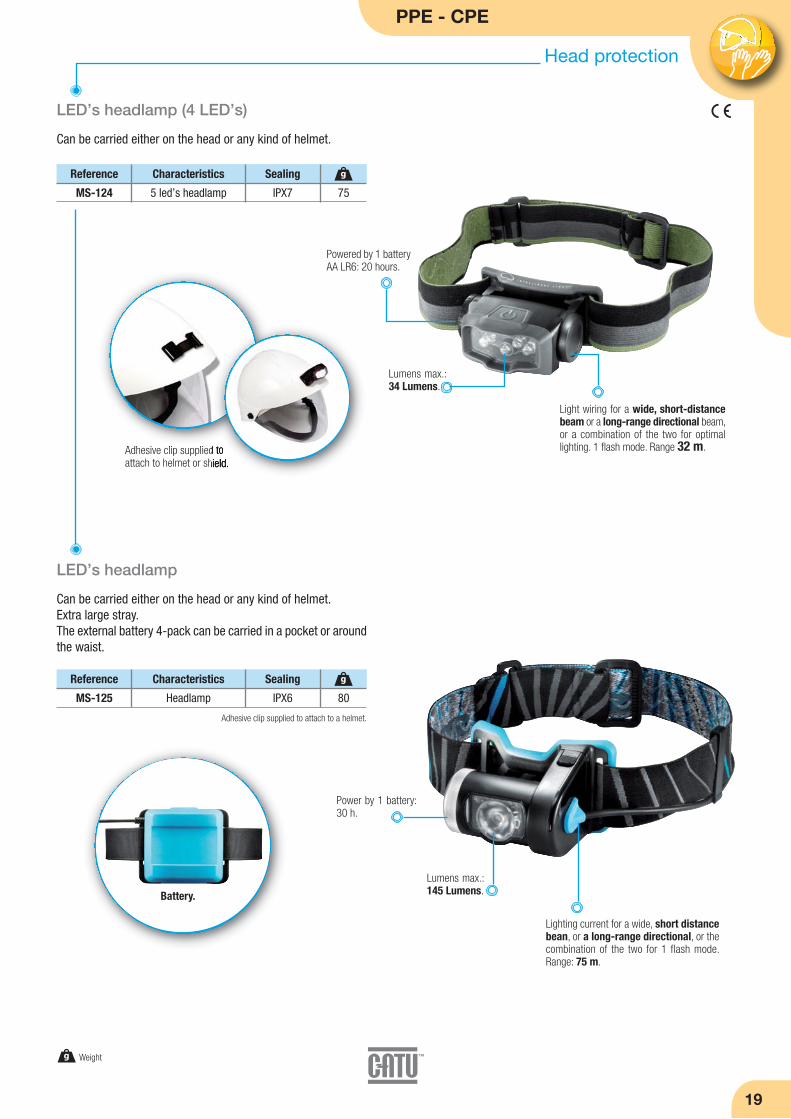
75
g
LED’s headlamp (4 LED’s)
Can be carried either on the head or any kind of helmet.
MS-124 5 led’s headlamp IPX7
Reference Characteristics Sealing
80
g
LED’s headlamp
Can be carried either on the head or any kind of helmet.Extra large stray .The external battery 4-pack can be carried in a pocket or aroundthe waist.
MS-125 Headlamp IPX6
Reference Characteristics Sealing
Light wiring for a wide, short-distancebeam or a long-range directional beam,or a combination of the two for optimallighting. 1 flash mode. Range 32 m.
Lumens max.:34 Lumens.
Powered by 1 batteryAA LR6: 20 hours.
Lighting current for a wide, short distancebean, or a long-range directional, or thecombination of the two for 1 flash mode.Range: 75 m.
Lumens max.:145 Lumens.
Power by 1 battery:30 h.
Adhesive clip supplied to attach to a helmet.

20
Insulating rubber glovesAn essential choice for safety!
Compliance.
Insulating gloves offer personal protection against electrical shockswhen working on or near live wires.They must comply with the IEC 60903 and EN 60903standards. As a result, they undergo various voltage,ageing, and mechanical testing.
The gloves are individually tested and sold ina sealed plastic bag.
Glove Types, Classes, and Categories.
There are 2 main types of insulating gloves:- Latex gloves provide high dielectric performance. They must be used with leather glove covers for mechanical protection.- Composite gloves offer superior mechanical protection against punctures and tears. They eliminate the need for overgloves.
• Insulating gloves should be chosen according to their class,which corresponds the voltage level used.
• Insulating gloves can have other environmental resistance pro-perties, and they are classified into categories.
CHARACTERISTICS OF SYMBOLS
• Label with a double triangle symbolIEC 60 417-5216, suitable for workon live wires.
• Label with a mechanical hammersymbol, indicating composite gloves.
Class
00
0
1
2
3
4
750 V
1 500 V
11 250 V
25 500 V
39 750 V
54 000 V
DCAC
500 Veffective
1 000 Veffective
7 500 Veffective
17 000 Veffective
26 500 Veffective
36 000 Veffective
Category
A
H
Z
R
C
Acid
Oil
Ozone
Acid, Oil, and Ozone
Very low temperature
Resisting in
Note 1: Category R combines the characteristics of Categories A, H, and Z.Note 2: Any category combination may be used.
LOT : 8019
00 / RCIEC 60903 : 2003
06 09
10 SUP
CG-05C
Class. Category.
Compliance with the 2003IEC 60903 standard.
Month, logo,and year ofmanufacture
Size.
Traceability
Marking area showingthe date of first useand periodic testingdates.
IEC or ENmarking
CE markingrequired.
Symbol appears only oncomposite gloves
CG-30
CG-02
All our gloves provide greater comfort and hygiene when used.

PPE - CPE
Insulating gloves
21
All insulating gloves must be visible inspected afterinflation and before each use.
For Classes 0 and 00: The tests consist of an air in-flation test and a visual inspection when the gloveis inflated. The dielectric test is not required, but itmay be performed at the owner's request.
For Classes 1, 2, 3, and 4: Even when in storage, a glove can-not be used without having been tested within the last sixmonths. Normal testing periods are between 30 and 90 days.
An inspection of the inside of the gloves is also recommended.Gloves should be stored in their packaging, without being com-pressed or folded. They should not be stored near a heat sourcewith a temperature of 10 to 21°C.
Inspection and Storage of Insulating Gloves.
Insulating Latex Gloves
Gloves without mechanical protection for use with silicon leather glove covers.
Insulating latex glove to glove cover size conversion table
Reference ClassThickness max. mmVoltage
CG-05-(*)
CG-10-(*)
CG-15-(*)
CG-20-(*)
CG-30-(*)
CG-40-(*)
00
0
1
2
3
4
≤ 500 V
≤ 1 000 V
≤ 7 500 V
≤ 17 000 V
≤ 26 500 V
≤ 36 000 V
0.5
1
1.5
2.3
2.9
3.6
Category
AZC
RC
RC
RC
RC
AZC
360
360
360
360
360
410
150
220
270
450
560
800
g
GLOVES Reference GLOVES Size
CG-05-(*)
CG-10-(*)
CG-15-(*)
CG-20-(*)
CG-30-(*)
CG-40-(*)
A = 8
B = 9
C = 10
D = 11
A = 8
B = 9
C = 10
D = 11
OVERGLOVES Reference OVERGLOVES Size OVERGLOVES
CG-98-(*)
CG-99-(**)
A = 8
B = 9
C = 10
D = 11
C = 10
D = 11
E = 12
GLOVES
EN 60903 / IEC 60903
(*) References to be completed by size A, B, C or D.(**) References to be completed by size C, D or E.
g Weight
CG-10
Class 00 Class 0 Class 1 Class 2 Class 3 Class 4
mm
mm Total length
(*) Reference to be completed by size A, B, C ou D.CG-05 to CG-20 : A, B, C, D.
CG-30 : B, C, D.CG-40 : C, D.

Cat.
RC
RC
RC
RC
360
360
410
410
mm
22
Composite gloves
Insulating gloves with higher mechanical properties for working in full safetywithout leather overgloves.
Pneumatic glove tester
For compulsory control of gloves before use.Checking is done by inflating and immersing in water.
Reference ClassThickness max. mm
Voltage
CG-02-(*)
CG-12-(*)
CG-16-(**)
CG-22-(**)
00
0
1
2
≤ 500 V
≤ 1 000 V
≤ 7 500 V
≤ 17 000 V
1.8
2.3
2.8
3.3
(*) References to be completed by size A, B, C, or D.(**) References to be completed by size B, C, or D.
Insulating gloves
Conventional gloves
Thickness max. mm
Voltage
CGL-20-(*)
CGL-30-(*)
2
3
≤ 17 000 V
≤ 26 500 V
3.3
3.6
(*) References to be completed by size B or C.
Long Gloves Long composite glovesfor insulating the handand arm.
EN 60903 / IEC 60903
Reference Characteristics
CG-117 * Pneumatic glove tester 600
g
Gloves box
Specially designed for protecting insulating gloves.Can be fixed on wall.
Reference
CG-35/2 * 101 x 224 x 476 770
gmm
* Delivered in cardboard140 x 150 x 160.
* Includes a bottle of talcum powder and precautions for use on tape positioned according to the language (English, French, Spanish,
German, Italian, Portuguese, Arabic dutch, Chinese, Russian).
mm Dimensions
Recommendedmaintenancereminders.
The transparent coverenables to check glovespresence. UV resistant.
Insulating gloves "arc flash"
See page 27.
Cat.
AZC
AZC
800
800
mm
1 800
2 040
g
300
350
580
620
g
Reference Class
mm Total length g Weight
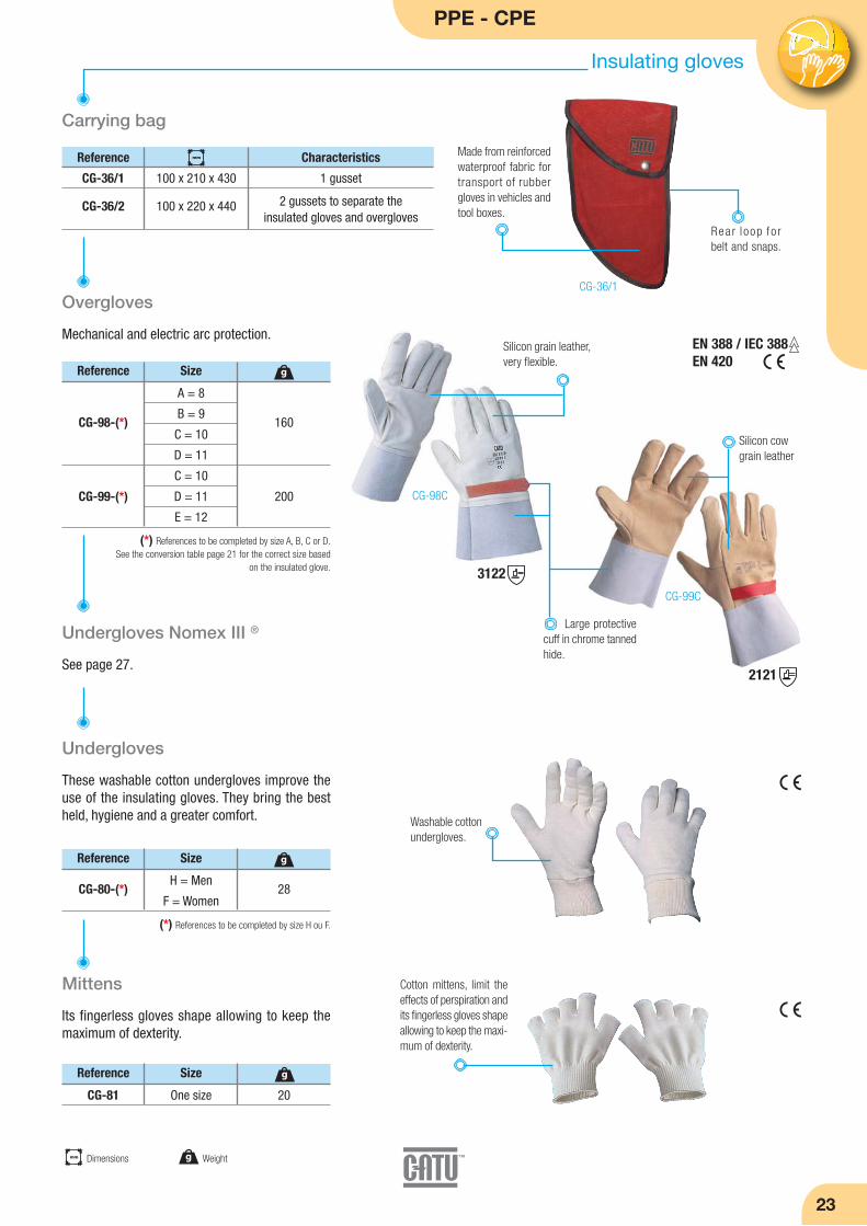
Rea r l oop fo rbelt and snaps.
EN 388 / IEC 388EN 420
PPE - CPE
23
Carrying bag
Overgloves
Mechanical and electric arc protection.
Undergloves
Insulating gloves
Reference Characteristics
CG-36/1
CG-36/2
100 x 210 x 430
100 x 220 x 440
1 gusset
2 gussets to separate the insulated gloves and overgloves
mm
Reference
160
200
g
Made from reinforced waterproof fabric fortransport of rubbergloves in vehicles andtool boxes.
(*) References to be completed by size A, B, C or D.See the conversion table page 21 for the correct size based
on the insulated glove.
A = 8
B = 9
C = 10
D = 11
C = 10
D = 11
E = 12
CG-98-(*)
CG-99-(*)
Size
Reference
28
g
(*) References to be completed by size H ou F.
H = Men
F = WomenCG-80-(*)
Size
3122
2121
Silicon grain leather,very flexible.
CG-98C
Large protective cuff in chrome tannedhide.
CG-99C
These washable cotton undergloves improve theuse of the insulating gloves. They bring the bestheld, hygiene and a greater comfort.
Mittens
Its fingerless gloves shape allowing to keep themaximum of dexterity.
Washable cottonundergloves.
Cotton mittens, limit theeffects of perspiration andits fingerless gloves shapeallowing to keep the maxi-mum of dexterity.
Reference Size
CG-81 One size 20
g
mm Dimensions g Weight
Undergloves Nomex III ®
See page 27.
Silicon cowgrain leather
CG-36/1

24
Insulating boots and mats
Insulating boots
Reference
(*) Add sizes: 39, 40/41, 42, 43, 44, 45, 46/47, 48, 49/50.Example: MV-135-40/41.
MV-135-(*)
MV-134-(*)
Voltage
20 000 V
1 000 V
Standards
ISO EN 20345ISO EN 20347
EN 50321 - Classe 0
EN 13287
ISO EN 20345ISO EN 20347
Protection against step and touch hazardous potential gradients.
Made from high qualitydielectrical rubber, veryflexible and resistant.
Anti-perforation compositesole and shell. Anti-slipsole. EN 13287.
Safety tip in technicalpolymer.
External height370 mm.
MV-135MV-134
Insulating mats
Individual models
VoltageThickness
mm
MP-42/11
MP-42/16
MP-42/66
3
3
3
≤ 26.5 kV
≤ 26.5 kV
≤ 26.5 kV
1 000 x 1 000
600 x 1 000
600 x 600
4 500
2 900
1 800
gmm
3
3
3
For placing in front of panels
VoltageThickness
mm
MP-60/03-5
MP-60/03-10
MP-100/03-5
MP-100/03-10
MP-60/05-5
MP-60/05-10
MP-100/05-5
MP-100/05-10
3
3
3
3
4
4
4
4
≤ 26.5 kV
≤ 26.5 kV
≤ 26.5 kV
≤ 26.5 kV
≤ 36 kV
≤ 36 kV
≤ 36 kV
≤ 36 kV
600 x 5 000
600 x 10 000
1 000 x 5 000
1 000 x 10 000
600 x 5 000
600 x 10 000
1 000 x 5 000
1 000 x 10 000
14 000
28 000
25 000
53 500
28 000
44 000
45 000
89 000
gmm
3
3
3
3
5
5
5
5
Insulating mats
Adapted to High Voltage.
Reference
MP-100/10-5
MP-100/10-10
1 000 x 5 000
1 000 x 10 000
87 000
154 000
gmm
10
10
High quality dielectricalrubber.
Regulatory markclearly indicatingthe mat features.
High qualitydielectricalrubber.
IEC 61111EN 61111
Non-skid surface.
Non-skid surface.
Contact us for any particular application.
Thickness mm
Reference Class
Reference Class
mm Dimensions g Weight

PPE - CPE
25
Accessories and insulating platforms
Bags for insulating mats
Specially designed for carrying and protecting insulatingmats. Equipped with a shoulder strap.
plastic window for instructionsand storage identification.
Reference
MP-01
MP-02
700
1 100
mm
For MP-42/16 and MP-42/66
For MP-42/11
Characteristics
Insulating platforms (indoor models)
CT-7-25/1
CT-7-40/1
220
260
UNE 204 001 ≤ 36 kV
UNE 204 001 ≤ 45 kV
3 700
3 800
g
Insulating platform (outdoor model)
Reference Ratedinsulation
Number of
skirts/foot
CT-9-25
CT-9-45
CT-9-63
2
3
4
≤ 24 kV
≤ 45 kV
≤ 63 kV
6 000
6 500
7 000
g
Moulded insulatingmaterial, one-piece.
Top 50 x 50 cm.
Insulating platforms (indoor models)
Adapted to the B High Voltage.
Reference Ratedinsulation
Heightmm
CT-7-63 515≤ 63 kV 3 350
gRemovable feetwith rubber tips.
Solid plate with mouldedinsulating material 52 x52 cm, thickness 40 cm.
Heightmm
350
435
515
Feet with rubbertips.
Insulatingskirts.
Solid plate with mouldedinsulating material 52 x52 cm, thickness 40 cm.
Multi-pockets electrician bag
Specially designed for carrying and protecting insulating mats, face shield and controllers.
Equipped with severalpockets.
Reference
M-87386 650 x 150 x 250 850
gmm
8 0 0 - d e n i e rdust resistantnylon with PVCcoating.
Lockable.
Rated insulation
≤ 24 kV
≤ 40 kV
4
5
ClassReference Standards Heightmm
mm Dimensionsmm Total length g Weight
26
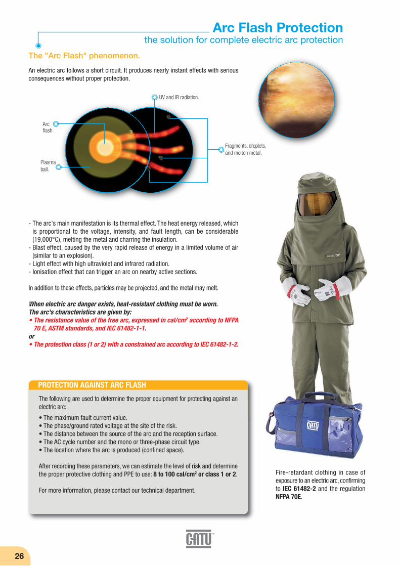
- The arc's main manifestation is its thermal effect. The heat energy released, whichis proportional to the voltage, intensity, and fault length, can be considerable(19,000°C), melting the metal and charring the insulation.
- Blast effect, caused by the very rapid release of energy in a limited volume of air(similar to an explosion).
- Light effect with high ultraviolet and infrared radiation.- Ionisation effect that can trigger an arc on nearby active sections.
In addition to these effects, particles may be projected, and the metal may melt.
When electric arc danger exists, heat-resistant clothing must be worn.The arc's characteristics are given by:• The resistance value of the free arc, expressed in cal/cm2 according to NFPA
70 E, ASTM standards, and IEC 61482-1-1.or• The protection class (1 or 2) with a constrained arc according to IEC 61482-1-2.
Arc Flash Protectionthe solution for complete electric arc protection
The "Arc Flash" phenomenon.
UV and IR radiation.
Arcflash.
Fragments, droplets,and molten metal.
Plasmaball.
PROTECTION AGAINST ARC FLASH
The following are used to determine the proper equipment for protecting against anelectric arc:
• The maximum fault current value.• The phase/ground rated voltage at the site of the risk.• The distance between the source of the arc and the reception surface.• The AC cycle number and the mono or three-phase circuit type.• The location where the arc is produced (confined space).
After recording these parameters, we can estimate the level of risk and determinethe proper protective clothing and PPE to use: 8 to 100 cal/cm2 or class 1 or 2.
For more information, please contact our technical department.
Fire-retardant clothing in case of exposure to an electric arc, confirmingto IEC 61482-2 and the regulationNFPA 70E.
An electric arc follows a short circuit. It produces nearly instant effects with seriousconsequences without proper protection.
PPE - CPE
Arc Flash protection
27
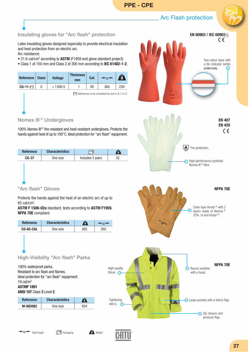
Insulating gloves for "Arc flash" protection
Latex insulating gloves designed especially to provide electrical insulationand heat protection from an electric arc.Arc resistance:• 21.6 cal/cm2 according to ASTM (F1959 and glove standard project).• Class 1 at 150 mm and Class 2 at 300 mm according to IEC 61482-1-2.
(*) References to be completed by size A, B, C or D.
Nomex III ® Undergloves
100% Nomex III ® fire-resistant and heat-resistant undergloves. Protects thehands against heat of up to 100°C. Ideal protection for "arc flash" equipment.
Two-colour latex witha life indicator (whiteundercoat).
High performance syntheticNomex III ® fibre.
Reference
CG-37
Characteristics
One size 32
g
High-Visibility "Arc flash" Parka
100% waterproof parka.Resistant to arc flash and flames.Ideal protection for "arc flash" equipment.19 cal/m2
ASTMF 1891ANSI 107 Class 3 Level 2.
Reference
M-882082
Characteristics
One size 924
g
"Arc flash" Gloves
Reference
CG-65-CAL
Characteristics
One size 265
g
Outer layer Kevlar ® with 2layers made of Nomex ®
33%. of and Kevlar ®.
NFPA 70E
Thickness mmVoltage
CG-11-(*) 0 ≤ 1 000 V 1
Cat.
RC 360
mm
230
gReference Class
Includes 5 pairs
355
mm
EN 407EN 420
NFPA 70E
Large pockets with a Velcro flap.
Zip closure andpressure flap.
Tighteningvelcro.
Hight qualitytissue.
Round necklinewith a hood.
mm Total length Packaging g Weight
Protects the hands against the heat of an electric arc of up to65 cal/cm2.ASTM F 1506-02a standard, tests according to ASTM F1959.NFPA 70E compliant.
Fire protection.
EN 60903 / IEC 60903
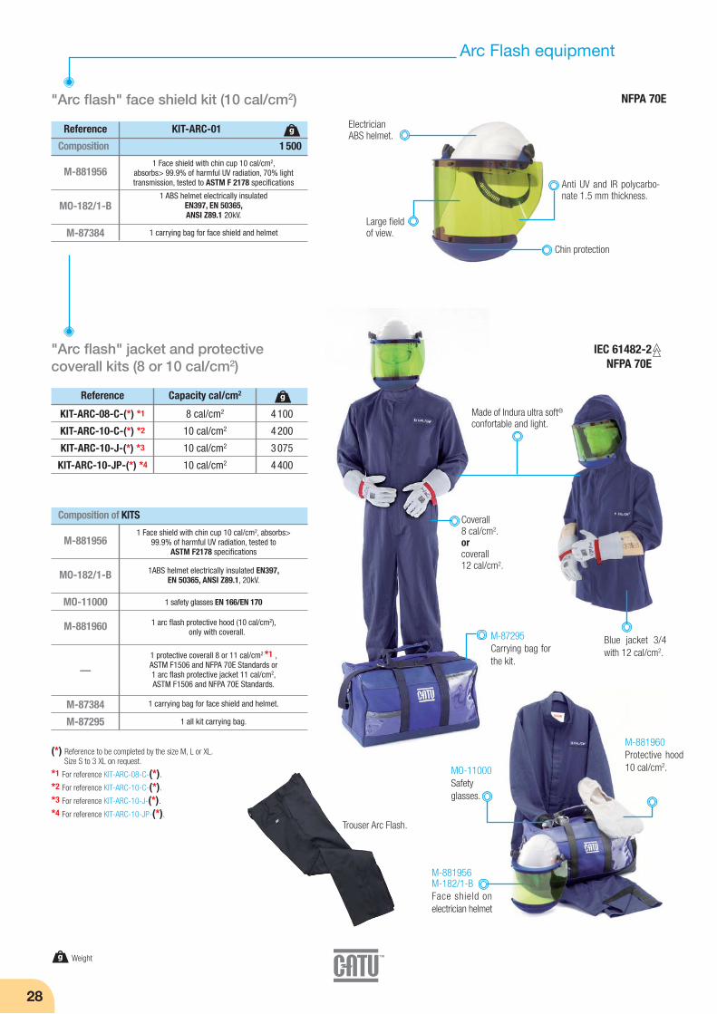
28
Arc Flash equipment
"Arc flash" face shield kit (10 cal/cm2)
Composition 1 500
M-881956
MO-182/1-B
M-87384
Reference KIT-ARC-01
1 Face shield with chin cup 10 cal/cm2, absorbs> 99.9% of harmful UV radiation, 70% light transmission, tested to ASTM F 2178 specifications
1 ABS helmet electrically insulated EN397, EN 50365, ANSI Z89.1 20kV.
1 carrying bag for face shield and helmet
g
"Arc flash" jacket and protective coverall kits (8 or 10 cal/cm2)
M-881956
MO-182/1-B
MO-11000
M-881960
—
M-87384
M-87295
1 Face shield with chin cup 10 cal/cm2, absorbs> 99.9% of harmful UV radiation, tested to
ASTM F2178 specifications
1ABS helmet electrically insulated EN397, EN 50365, ANSI Z89.1, 20kV.
1 safety glasses EN 166/EN 170
1 arc flash protective hood (10 cal/cm2), only with coverall.
1 protective coverall 8 or 11 cal/cm2 *1 , ASTM F1506 and NFPA 70E Standards or1 arc flash protective jacket 11 cal/cm2, ASTM F1506 and NFPA 70E Standards.
1 carrying bag for face shield and helmet.
1 all kit carrying bag.
(*) Reference to be completed by the size M, L or XL.Size S to 3 XL on request.
*1 For reference KIT-ARC-08-C-(*).
*2 For reference KIT-ARC-10-C-(*).
*3 For reference KIT-ARC-10-J-(*).
*4 For reference KIT-ARC-10-JP-(*).
Blue jacket 3/4with 12 cal/cm2.
M-881960Protective hood10 cal/cm2.MO-11000
Safetyglasses.
M-881956M-182/1-BFace shield onelectrician helmet
Coverall8 cal/cm2.orcoverall12 cal/cm2.
M-87295Carrying bag forthe kit.
Reference
KIT-ARC-08-C-(*) *1
KIT-ARC-10-C-(*) *2
KIT-ARC-10-J-(*) *3
KIT-ARC-10-JP-(*) *4
Capacity cal/cm2
8 cal/cm2
10 cal/cm2
10 cal/cm2
10 cal/cm2
4 100
4 200
3 075
4 400
g
Composition of KITS
IEC 61482-2 NFPA 70E
g Weight
NFPA 70E
ElectricianABS helmet.
Large fieldof view.
Chin protection
Anti UV and IR polycarbo-nate 1.5 mm thickness.
Made of Indura ultra soft®confortable and light.
Trouser Arc Flash.
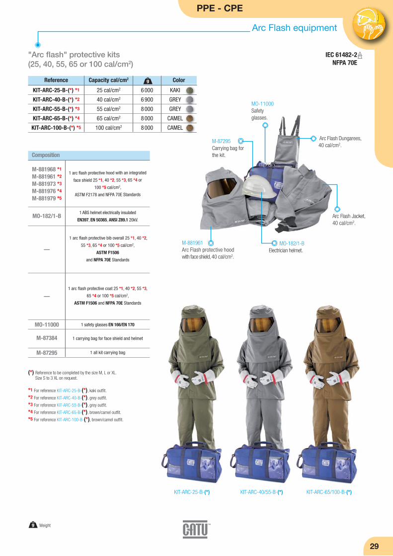
PPE - CPE
29
Arc Flash equipment
"Arc flash" protective kits (25, 40, 55, 65 or 100 cal/cm2)
KIT-ARC-40/55-B-(*)KIT-ARC-25-B-(*) KIT-ARC-65/100-B-(*)
Reference
KIT-ARC-25-B-(*) *1
KIT-ARC-40-B-(*) *2
KIT-ARC-55-B-(*) *3
KIT-ARC-65-B-(*) *4
KIT-ARC-100-B-(*) *5
Capacity cal/cm2
25 cal/cm2
40 cal/cm2
55 cal/cm2
65 cal/cm2
100 cal/cm2
6 000
6 900
8 000
8 000
8 000
KAKI
GREY
GREY
CAMEL
CAMEL
g
MO-182/1-B
MO-11000
M-87384
M-87295
(*) Reference to be completed by the size M, L or XL.Size S to 3 XL on request.
*1 For reference KIT-ARC-25-B-(*), kaki outfit.
*2 For reference KIT-ARC-40-B-(*), grey outfit.
*3 For reference KIT-ARC-55-B-(*), grey outfit.
*4 For reference KIT-ARC-65-B-(*), brown/camel outfit.
*5 For reference KIT-ARC-100-B-(*), brown/camel outfit.
Composition
M-881968 *1
M-881961 *2
M-881973 *3
M-881976 *4
M-881979 *5
1 arc flash protective hood with an integrated
face shield 25 *1, 40 *2, 55 *3, 65 *4 or
100 *5 cal/cm2,
ASTM F2178 and NFPA 70E Standards
1 ABS helmet electrically insulated
EN397, EN 50365, ANSI Z89.1 20kV.
—
1 safety glasses EN 166/EN 170
1 carrying bag for face shield and helmet
1 all kit carrying bag
1 arc flash protective bib overall 25 *1, 40 *2,
55 *3, 65 *4 or 100 *5 cal/cm2,
ASTM F1506
and NFPA 70E Standards
1 arc flash protective coat 25 *1, 40 *2, 55 *3,
65 *4 or 100 *5 cal/cm2,
ASTM F1506 and NFPA 70E Standards
Color
—
M-87295Carrying bag forthe kit.
M-881961Arc Flash protective hoodwith face shield, 40 cal/cm2.
MO-182/1-BElectrician helmet.
MO-11000Safetyglasses.
Arc Flash Dungarees,40 cal/cm2.
Arc Flash Jacket, 40 cal/cm2.
IEC 61482-2 NFPA 70E
g Weight
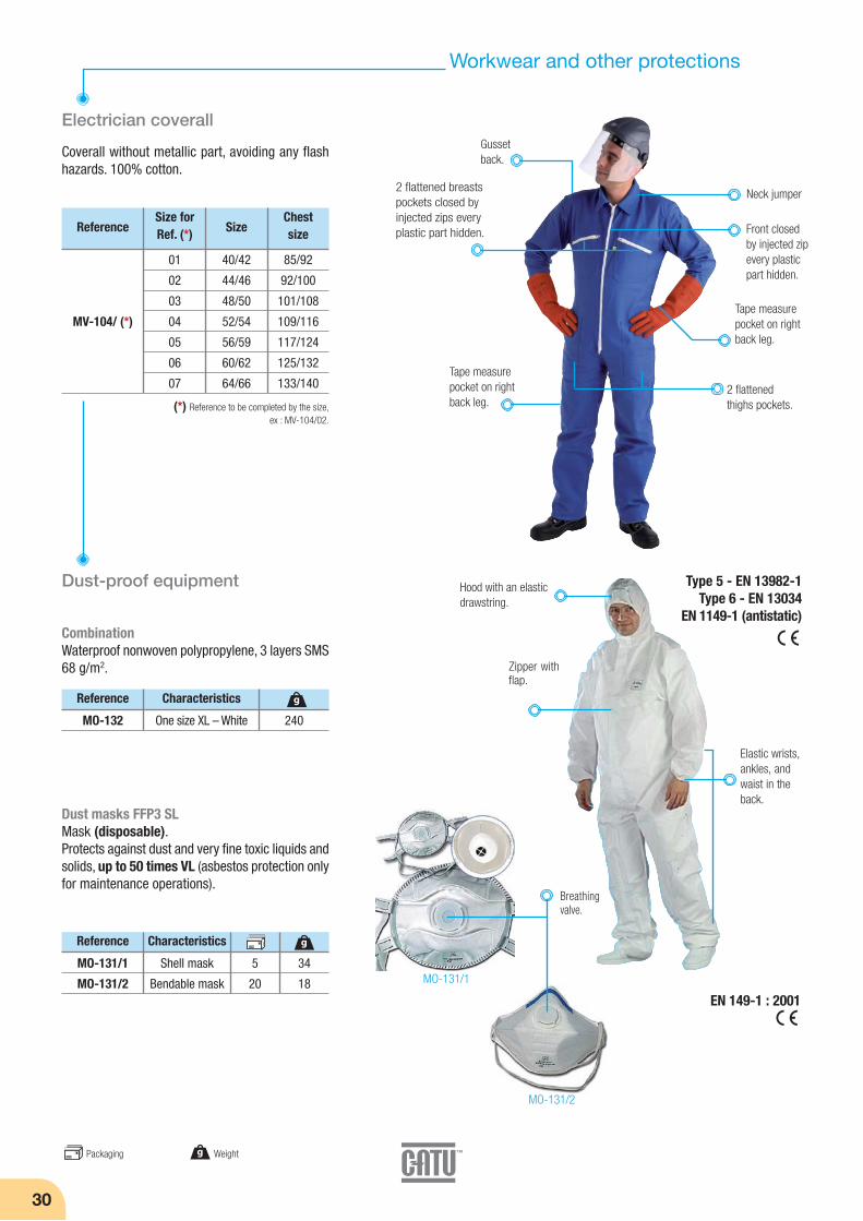
Tape measurepocket on rightback leg.
30
Workwear and other protections
Electrician coverall
Reference
(*) Reference to be completed by the size,ex : MV-104/02.
40/42
44/46
48/50
52/54
56/59
60/62
64/66
MV-104/ (*)
Size
85/92
92/100
101/108
109/116
117/124
125/132
133/140
Chest size
Coverall without metallic part, avoiding any flashhazards. 100% cotton.
Dust-proof equipment
CombinationWaterproof nonwoven polypropylene, 3 layers SMS68 g/m2.
Neck jumper
Gusset back.
2 flattened breastspockets closed byinjected zips everyplastic part hidden.
Hood with an elasticdrawstring.
Front closedby injected zipevery plasticpart hidden.
2 flattenedthighs pockets.
01
02
03
04
05
06
07
Size forRef. (*)
Tape measurepocket on rightback leg.
Type 5 - EN 13982-1Type 6 - EN 13034
EN 1149-1 (antistatic)
Zipper withflap.
Elastic wrists,ankles, andwaist in theback.
Reference
MO-132
Characteristics
One size XL – White 240
g
Dust masks FFP3 SLMask (disposable).Protects against dust and very fine toxic liquids andsolids, up to 50 times VL (asbestos protection onlyfor maintenance operations).
Reference
MO-131/1
MO-131/2
Characteristics
Shell mask
Bendable mask
34
18
5
20
g
EN 149-1 : 2001
MO-131/1
MO-131/2
Breathingvalve.
g WeightPackaging
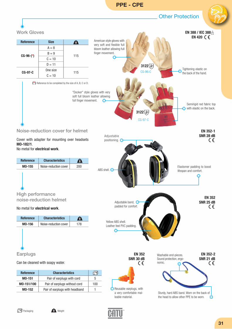
PPE - CPE
Other Protection
31
Reference
MO-155
Characteristics
Noise-reduction cover 200
g
Work Gloves
Noise-reduction cover for helmet
Reference
115
115
g
(*) Reference to be completed by the size of A, B, C or D.
A = 8
B = 9
C = 10
D = 11
One size
C = 10
CG-96-(*)
CG-97-C
Size
EN 388 / IEC 388EN 420
CG-96-C
CG-97-C
Tightening elastic onthe back of the hand.
American style gloves withvery soft and flexible fullbloom leather allowing fullfinger movement.
"Docker" style gloves with verysoft full bloom leather allowingfull finger movement.
Semirigid red fabric topwith elastic on the back.
Cover with adapter for mounting over headsetsMO-182/1.No metal for electrical work.
Elastomer padding to boostlifespan and comfort.
Adjustablepositioning.
EN 352-1SNR 28 dB
Reference
MO-156
Characteristics
Noise-reduction cover 178
g
High performance noise-reduction helmet
No metal for electrical work.
Reference
MO-151
MO-151/100
MO-152
Characteristics
Pair of earplugs with cord
Pair of earplugs without cord
Pair of earplugs with headband
Earplugs
Can be cleaned with soapy water.
EN 352SNR 25 dBAdjustable band,
padded for comfort.
Yellow ABS shell.Leather feel PVC padding.
Reusable earplugs, witha very comfortable mal-leable material.
Washable end-pieces.Sound protection, ergo-nomic.
Sturdy, hard ABS band. Worn on the back ofthe head to allow other PPE to be worn.
g Weight
3122
3122
EN 352-2SNR 21 dB
EN 352SNR 30 dB
ABS shell.
5
100
1
Packaging
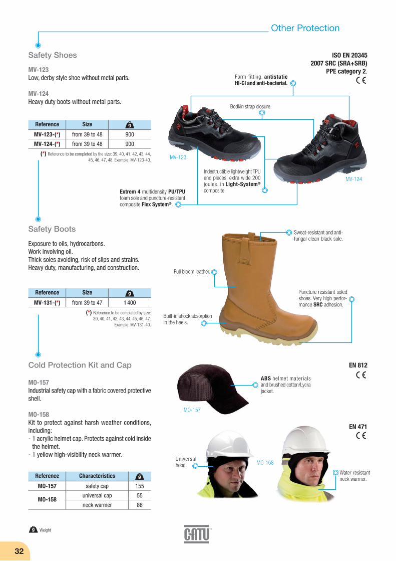
32
Safety Shoes
Other Protection
Reference
900
900
g
(*) Reference to be completed by the size: 39, 40, 41, 42, 43, 44,45, 46, 47, 48. Example: MV-123-40.
from 39 to 48
from 39 to 48
MV-123-(*)
MV-124-(*)
Size
Safety Boots
Exposure to oils, hydrocarbons.Work involving oil.Thick soles avoiding, risk of slips and strains.Heavy duty, manufacturing, and construction.
Reference
1 400
g
(*) Reference to be completed by size:39, 40, 41, 42, 43, 44, 45, 46, 47.
Example: MV-131-40.
from 39 to 47MV-131-(*)
Size
Reference
MO-157
MO-158
Characteristics
safety cap
universal cap
neck warmer
Cold Protection Kit and Cap
MO-157Industrial safety cap with a fabric covered protectiveshell.
MO-158Kit to protect against harsh weather conditions, including:- 1 acrylic helmet cap. Protects against cold inside
the helmet.- 1 yellow high-visibility neck warmer.
g Weight
Built-in shock absorptionin the heels.
MV-124
MV-123
Puncture resistant soledshoes. Very high perfor-mance SRC adhesion.
Sweat-resistant and anti-fungal clean black sole.
Full bloom leather.
MV-123Low, derby style shoe without metal parts.
MV-124Heavy duty boots without metal parts.
EN 812
EN 471
ISO EN 203452007 SRC (SRA+SRB)
PPE category 2.
Bodkin strap closure.
Indestructible lightweight TPUend pieces, extra wide 200joules. in Light-System®
composite.
Form-fitting, antistaticHI-CI and anti-bacterial.
Extrem 4 multidensity PU/TPUfoam sole and puncture-resistantcomposite Flex System®.
155
55
86
g
ABS helmet materialsand brushed cotton/Lycrajacket.
MO-157
MO-158Universalhood.
Water-resistantneck warmer.

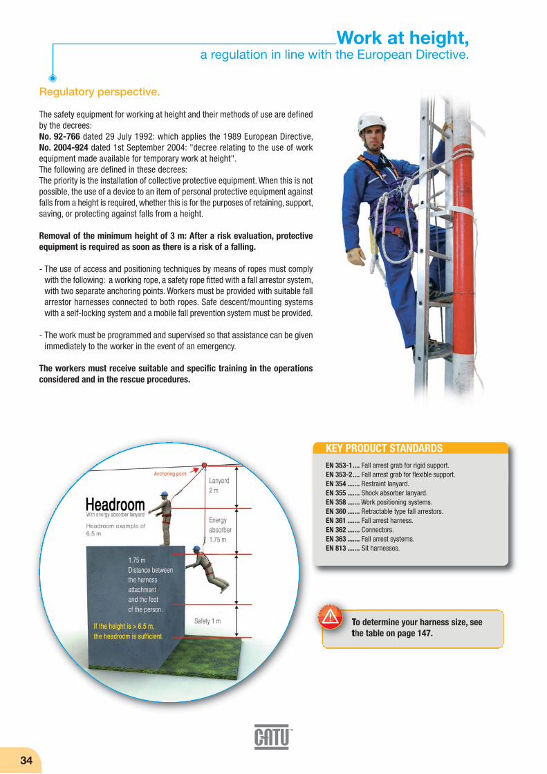
34
Work at height,a regulation in line with the European Directive.
Regulatory perspective.
The safety equipment for working at height and their methods of use are definedby the decrees:No. 92-766 dated 29 July 1992: which applies the 1989 European Directive, No. 2004-924 dated 1st September 2004: "decree relating to the use of workequipment made available for temporary work at height".The following are defined in these decrees:The priority is the installation of collective protective equipment. When this is notpossible, the use of a device to an item of personal protective equipment againstfalls from a height is required, whether this is for the purposes of retaining, support,saving, or protecting against falls from a height.
Removal of the minimum height of 3 m: After a risk evaluation, protectiveequipment is required as soon as there is a risk of a falling.
- The use of access and positioning techniques by means of ropes must complywith the following: a working rope, a safety rope fitted with a fall arrestor system,with two separate anchoring points. Workers must be provided with suitable fallarrestor harnesses connected to both ropes. Safe descent/mounting systemswith a self-locking system and a mobile fall prevention system must be provided.
- The work must be programmed and supervised so that assistance can be givenimmediately to the worker in the event of an emergency.
The workers must receive suitable and specific training in the operationsconsidered and in the rescue procedures.
KEY PRODUCT STANDARDSEN 353-1.... Fall arrest grab for rigid support.EN 353-2.... Fall arrest grab for flexible support.EN 354 ....... Restraint lanyard.EN 355 ....... Shock absorber lanyard.EN 358 ....... Work positioning systems.EN 360 ....... Retractable type fall arrestors.EN 361 ....... Fall arrest harness.EN 362 ....... Connectors.EN 363 ....... Fall arrest systems.EN 813 ....... Sit harnesses.
To determine your harness size, seethe table on page 147.
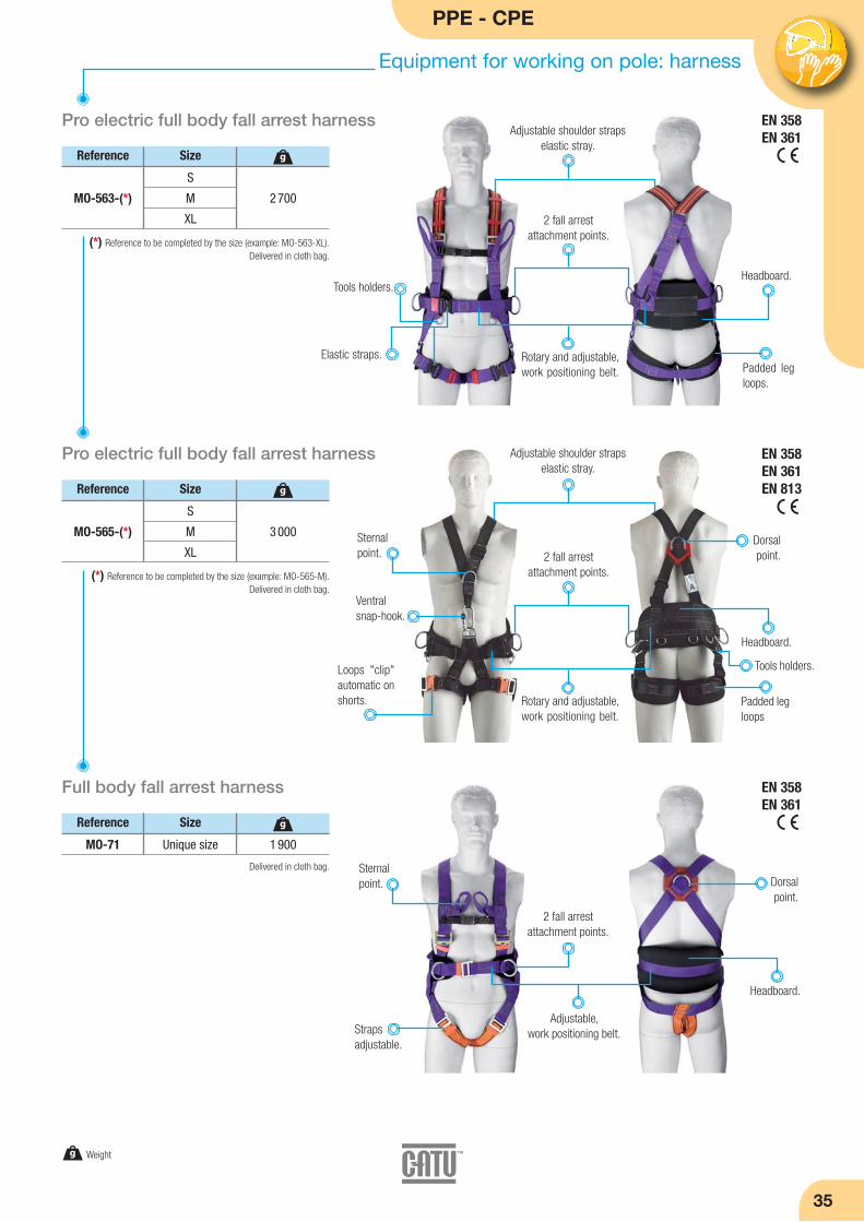
PPE - CPE
Equipment for working on pole: harness
35
Pro electric full body fall arrest harness
Reference
2 700
g
(*) Reference to be completed by the size (example: MO-563-XL).Delivered in cloth bag.
S
M
XL
MO-563-(*)
Size
Pro electric full body fall arrest harness
Reference
3 000
g
(*) Reference to be completed by the size (example: MO-565-M).Delivered in cloth bag.
S
M
XL
MO-565-(*)
Size
Full body fall arrest harness
Reference
1 900
g
Delivered in cloth bag.
Unique sizeMO-71
Size
Elastic straps. Rotary and adjustable,work positioning belt.
Headboard.
2 fall arrest attachment points.
Adjustable shoulder strapselastic stray.
Padded legloops.
EN 358EN 361
EN 358EN 361
EN 358EN 361EN 813
Ventral snap-hook.
Rotary and adjustable,work positioning belt.
Padded legloops
Headboard.
Dorsalpoint.
Sternal point.
Sternal point. Dorsal
point.
Adjustable, work positioning belt.Straps
adjustable.
Headboard.
Loops "clip"automatic onshorts.
2 fall arrest attachment points.
g Weight
Tools holders.
Tools holders.
Adjustable shoulder strapselastic stray.
2 fall arrest attachment points.
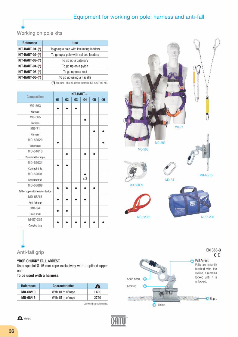
EN 353-3
36
Equipment for working on pole: harness and anti-fall
Working on pole kits
Reference
(*) Add size : M or XL (order example: KIT-HAUT-02-XL).
To go up a pole with insulating ladders
To go up a pole with spliced ladders
To go up a catenary
To go up on a pylon
To go up on a roof
To go up using a nacelle
KIT-HAUT-01-(*)
KIT-HAUT-02-(*)
KIT-HAUT-03-(*)
KIT-HAUT-04-(*)
KIT-HAUT-05-(*)
KIT-HAUT-06-(*)
Use
CompositionKIT-HAUT-…
01 02 03 04 05 06
MO-563
Harness
MO-565
Harness
MO-71
Harness
MO-52020
Tether rope
MO-54010
Double tether rope
MO-52034
Constraint tie
MO-52031
Constraint tie
MO-56009
Tether rope with tension device
MO-68/15
Anti-fall grip
MO-54
Snap hook
M-87-295
Carrying bag
x 2
M-87-295
MO-68/15MO-54
MO-71
MO-565
MO-56009
MO-52031
MO-563
Reference
MO-68/10
MO-68/15
Characteristics
With 10 m of rope
With 15 m of rope
1 600
2720
g
Anti-fall grip
“ROP CHUCK” FALL ARREST.Uses special Ø 15 mm rope exclusively with a spliced upperend.To be used with a harness.
Lifeline.
Snap hook.
Locking.
Rope.
Fall ArrestFalls are instantlyblocked with thelifeline. It remainslocked until it isunlocked.
Delivered complete only.
g Weight
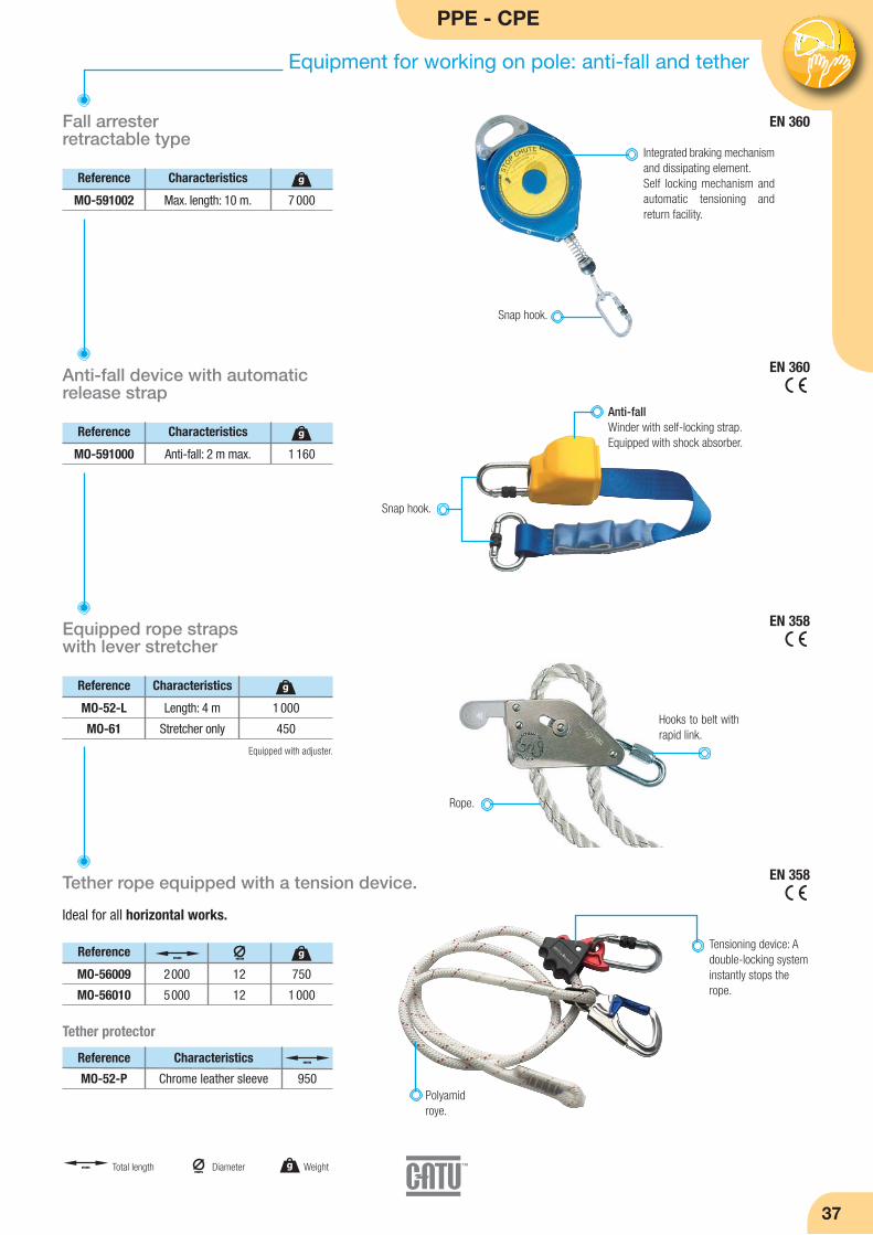
EN 360
PPE - CPE
Equipment for working on pole: anti-fall and tether
37
Equipped rope straps with lever stretcher
EN 360
Reference
MO-591002
Characteristics
Max. length: 10 m. 7 000
g
Fall arresterretractable type
Rope.
Reference Characteristics
MO-52-L
MO-61
Length: 4 m
Stretcher only
1 000
450
g
Tether rope equipped with a tension device.
Ideal for all horizontal works.
EN 358
EN 358
Equipped with adjuster.
Hooks to belt withrapid link.
Tensioning device: Adouble-locking systeminstantly stops therope.
Refe rence
MO-591000
Characteristics
Anti-fall: 2 m max. 1 160
g
Anti-fall device with automaticrelease strap
Snap hook.
Anti-fallWinder with self-locking strap.Equipped with shock absorber.
Snap hook.
Integrated braking mechanismand dissipating element.Self locking mechanism andautomatic tensioning and return facility.
Polyamidroye.
Reference
MO-56009
MO-56010
2000
5000
12
12
750
1 000
gmmmm
g Weightmm
Diametermm Total length
Reference Characteristics
MO-52-P Chrome leather sleeve 950
mm
Tether protector

38
Equipment for working on pole: tether and safety line
EN 355Double tether rope with energy absorber
Reference
MO-52020
MO-52021
Length: 1.5 m
Length: 2 m
1 100
1 200
g
1 steel snap hook withscrewing locking.
Strap adjuster.
Equipped with 2 steel snaphooks with automatic locking.
EN 355
EN 354
EN 795B
Double tether rope with energy absorber
Reference
MO-54010 Length: 1.20 m 1 400
g
Double lanyard
Reference
MO-53010 1000 12 1 400
gmm
Equipped with 2 steel snap hookswith automatic locking.
1 steel snap hook withscrewing locking.
mm
Can be connected to the harness by locking steelscrew karabiners.
Mobile safety line
Reference
MO-53002 5 to 20 m 2 000 Kg 2 820
g
Easy and quick to set up, this line can be used by 2people. It is equipped with a tension device.This safety line is designed for short operations. The users can then hook themselves to the safety lineusing a fall arrest device or a shock absorbing lanyard.When using a shock absorbing lanyard, allow for atleast 7 meters clearance.
Tether rope with energyabsorber.
Double tether rope with energyabsorber.
Two-strandnylon lanyardDouble-latch
karabiner, 50mm opening.
Adjustable strap.
Incorporated stretcher.
It has 2 harness rings withscrew gate karabiners.
Resistance
g Weightmm
Diametermm Total length
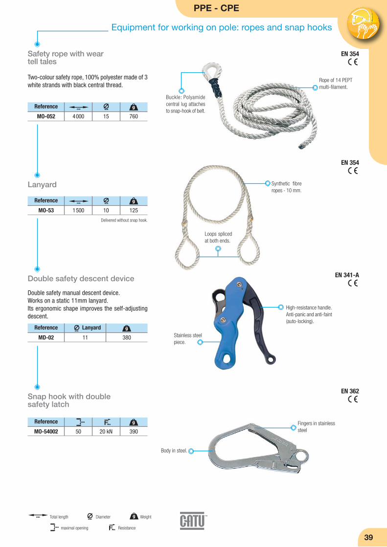
PPE - CPE
Equipment for working on pole: ropes and snap hooks
39
Double safety descent device
Double safety manual descent device.Works on a static 11mm lanyard.Its ergonomic shape improves the self-adjustingdescent.
High-resistance handle.Anti-panic and anti-faint(auto-locking).
Stainless steelpiece.
Reference
MD-02
Lanyard
11 380
gmm
Snap hook with double safety latch
EN 341-A
EN 362
EN 354Safety rope with wear tell tales
Reference
MO-052 4000 15 760
gmmmm
Two-colour safety rope, 100% polyester made of 3white strands with black central thread.
Rope of 14 PEPTmulti-filament.
EN 354
Lanyard
Reference
MO-53 1500 10 125
gmmmm
Synthetic fibreropes - 10 mm.
Loops splicedat both ends.
Delivered without snap hook.
Buckle: Polyamidecentral lug attachesto snap-hook of belt.
Reference
MO-54002 50 20 kN 390
gmm FNm
Body in steel.
Fingers in stainlesssteel
g Weightmm
Diametermm Total length
FNmmm Resistancemaximal opening
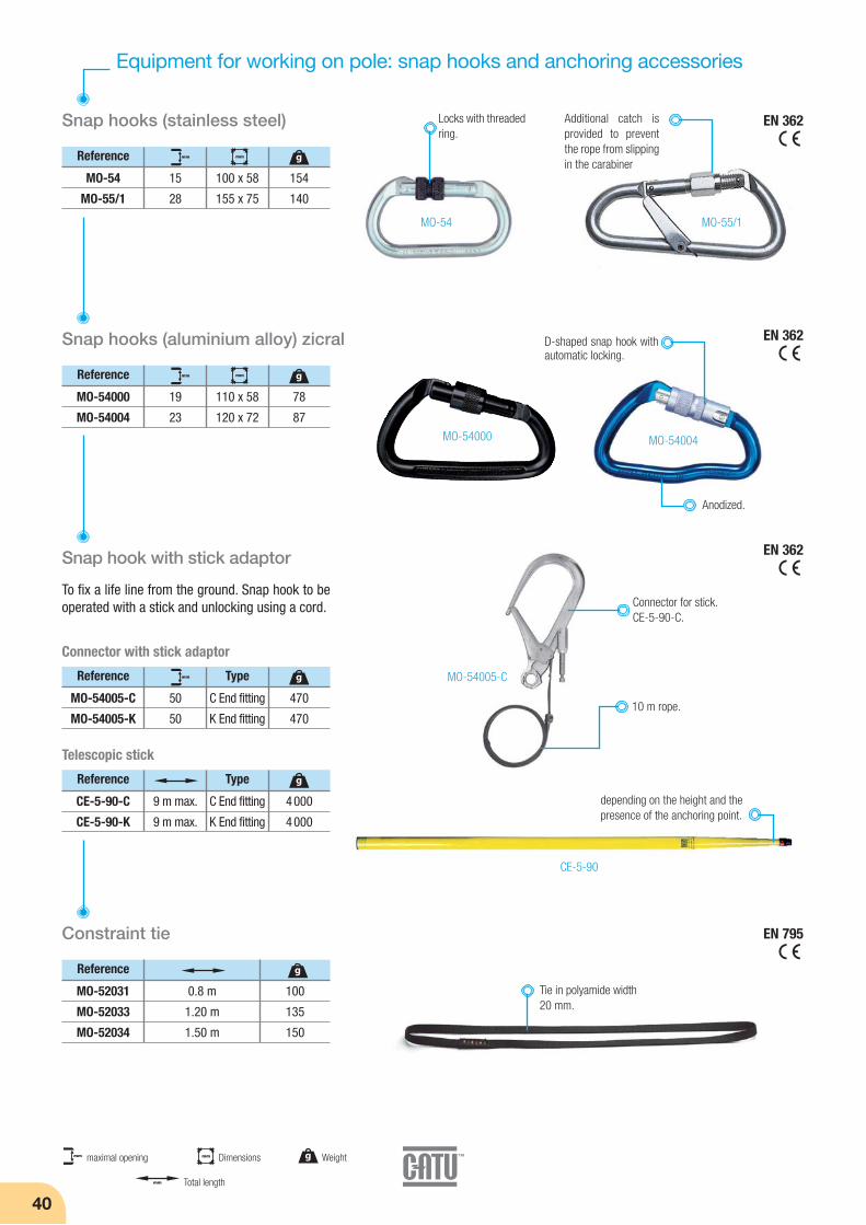
40
Equipment for working on pole: snap hooks and anchoring accessories
Snap hooks (stainless steel) EN 362
EN 362
EN 362
EN 795
Reference
MO-54
MO-55/1
15
28
100 x 58
155 x 75
154
140
gmm mm
Locks with threadedring.
Additional catch isprovided to preventthe rope from slippingin the carabiner
Snap hooks (aluminium alloy) zicral
Reference
MO-54000
MO-54004
19
23
110 x 58
120 x 72
78
87
gmm mm
Snap hook with stick adaptor
Reference Type
MO-54005-C
MO-54005-K
50
50
C End fitting
K End fitting
470
470
gmm
Reference
CE-5-90-C
CE-5-90-K
9 m max.
9 m max.
C End fitting
K End fitting
4 000
4 000
g
MO-54 MO-55/1
MO-54000 MO-54004
D-shaped snap hook withautomatic locking.
Telescopic stick
Connector with stick adaptor
Type
MO-54005-C
CE-5-90
depending on the height and the presence of the anchoring point.
Connector for stick.CE-5-90-C.
Tie in polyamide width20 mm.
10 m rope.
To fix a life line from the ground. Snap hook to beoperated with a stick and unlocking using a cord.
Constraint tie
Reference
MO-52031
MO-52033
MO-52034
0.8 m
1.20 m
1.50 m
100
135
150
g
g Weight
mm Total length
mm maximal opening mm Dimensions
Anodized.

PPE - CPE
Equipment for working on pole: climbers and accessories
41
Mechanical climbers for round andhexagonal concrete poles
Reference Pole
MO-16-A 140 > 300 6 500
gmm
Delivered by pair.
Forged steel climbers for roundwooden poles
Reference Pole
MO-24
MO-25
MO-26
MO-35
200
250
300
350
2 600
2 800
3 000
3 200
gmm
Mechanical climbers for rectangularshaped concrete poles
Tool bag for safety harness
Reference Pole width
MO-17-A 14 à 42 cm 9 000
g
Delivered by pair.
Delivered by pair.
Adaptable to the polediameter. For poles Ø140 to 300 mm.
Hard forged steel.
Leather belts withcast buckles.
Leather belts withcast buckles.
Leather belts withcast buckles.
NFS-071-012
For rectangular shaped concrete poles
Automatic locking ofjaws by elastic cord.
Wear plate placedon sole arm.Mobile drum on axis can
be removed; processedsteel rollers.
High resistance alumi-nium alloy rack, used forclamping onto poles 14to 42 cm wide.
Spare parts
Reference
MO-17-01
MO-17-02
MO-17-03
MO-17-04
Pair of elastic cords
Pair of wear plates
Blade roller
Pair of runners
Characteristics
Sole in aluminium alloy, highresistance, with leather beltsand steel buckle.
Reference
MO-32/3 250 x 230 x 100 835
gmm 2 pocket leatherpouch.
g Weightmm
Diameter mm Dimensions
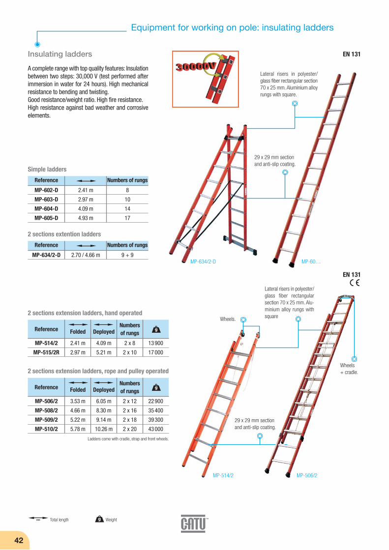
42
Equipment for working on pole: insulating ladders
Insulating ladders
Reference Numbers of rungs
MP-602-D
MP-603-D
MP-604-D
MP-605-D
2.41 m
2.97 m
4.09 m
4.93 m
8
10
14
17
Simple ladders
A complete range with top quality features: Insulationbetween two steps: 30,000 V (test performed afterimmersion in water for 24 hours). High mechanicalresistance to bending and twisting.Good resistance/weight ratio. High fire resistance.High resistance against bad weather and corrosiveelements.
Lateral risers in polyester/glass fiber rectangular section70 x 25 mm. Aluminium alloyrungs with square.
29 x 29 mm sectionand anti-slip coating.
EN 131
EN 131
Reference Folded DeployedNumbersof rungs
MP-514/2
MP-515/2R
2.41 m
2.97 m
4.09 m
5.21 m
2 x 8
2 x 10
13 900
17 000
2 sections extension ladders, hand operated
Reference Numbers of rungs
MP-634/2-D 2.70 / 4.66 m 9 + 9
2 sections extention ladders
Ladders come with cradle, strap and front wheels.
g
Reference Folded DeployedNumbersof rungs
MP-506/2
MP-508/2
MP-509/2
MP-510/2
3.53 m
4.66 m
5.22 m
5.78 m
6.05 m
8.30 m
9.14 m
10.26 m
2 x 12
2 x 16
2 x 18
2 x 20
22 900
35 400
39 300
43 000
2 sections extension ladders, rope and pulley operated
g
Lateral risers in polyester/glass fiber rectangularsection 70 x 25 mm. Alu-minium alloy rungs withsquare
MP-634/2-D MP-60…
MP-514/2 MP-506/2
mm Total length g Weight
Wheels.
Wheels+ cradle.
29 x 29 mm sectionand anti-slip coating.

PPE - CPE
43
Equipment for working on pole: insulating ladders and stepladders
Insulating stepladders
Insulation between two steps: 30 000 V
Standard extension ladders
MP-607/2-I
MP-608/2-I
MP-609/2-I
2 sections extension ladders, rope and pulley operated
Reference Folded DeployedNumbersof rungs
4.66 m
5.22 m
5.8 m
8.02 m
9.14 m
9.98 m
2 x 16
2 x 18
2 x 20
30 200
34 400
37 800
g
MP-607/3-I
MP-608/3-I
3 sections extension ladders, rope and pulley operated
Reference Folded DeployedNumbersof rungs
2.98 m
3.82 m
6.89 m
8.86 m
3 x 10
3 x 13
24 600
34 600
g
MP-700-4
MP-700-1
MP-700-2
MP-700-3
MP-700-5
ReferenceNbr
steps
HeightAccess
(m)
Heightfolded
(m)
Heightbased
feet (m)2.58
2.81
3.04
3.27
3.50
1.39
1.64
1.89
2.14
2.39
0.68
0.91
1.14
1.37
1.60
3
4
5
6
7
5 900
6 900
8 000
9 400
11 000
g
Folding stepladder with railing
Secure non-insulating platform.
MP-700-6
ReferenceNbr
stepsHeightAccess
Heightfolded
Heightbasedfeet
2.88 m 1.40 m 0.88 m4 19 500
g
Superior element lateral risersin polyester/ glass fiber.
Lower element in aluminium alloy.
Slimline8.8 cm.
Railing equippedwith a toolholder.
EN 131
MP-607/2-I MP-608/3-I
mm Total length g Weight
MP-700-2
Skirting on threesides.
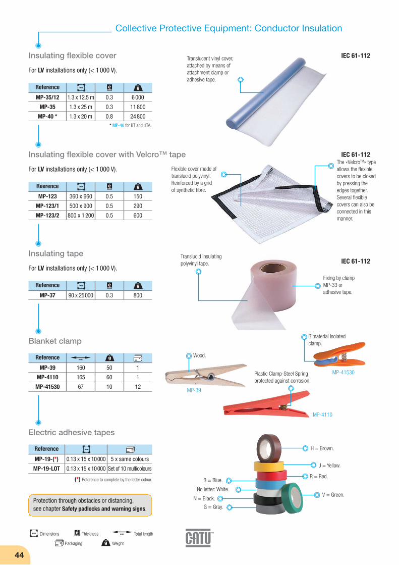
44
Collective Protective Equipment: Conductor Insulation
Insulating flexible cover
Reference
MP-35/12
MP-35
MP-40 *
1.3 x 12.5 m
1.3 x 25 m
1.3 x 20 m
0.3
0.3
0.8
6 000
11 800
24 800
For LV installations only (< 1 000 V).
Insulating flexible cover with Velcro™ tape
Reerence
MP-123
MP-123/1
MP-123/2
360 x 660
500 x 900
800 x 1 200
0.5
0.5
0.5
150
290
600
For LV installations only (< 1 000 V).
Insulating tape
Reference
MP-37 90 x 25000 0.3 800
For LV installations only (< 1 000 V).
Blanket clamp
Reference
MP-39
MP-4110
MP-41530
160
165
67
50
60
10
1
1
12
Translucent vinyl cover,attached by means ofattachment clamp oradhesive tape.
* MP-40 for BT and HTA.
Flexible cover made oftranslucid polyvinyl.Reinforced by a grid of synthetic fibre.
The «VelcroTM» typeallows the flexiblecovers to be closedby pressing theedges together.Several flexiblecovers can also beconnected in thismanner.
Translucid insulatingpolyvinyl tape.
Fixing by clampMP-33 or adhesive tape.
mm Dimensions
g Weight
mm Total lengthémm Thickness
gmm émm
gmm émm
g
g
mm émm
mm
Electric adhesive tapes
Reference
MP-19-(*)
MP-19-LOT
0.13 x 15 x 10000
0.13 x 15 x 10000
5 x same colours
Set of 10 multicolours
(*) Reference to complete by the letter colour.
mm
No letter: White.
R = Red.B = Blue.
V = Green.
J = Yellow.
G = Gray.
H = Brown.
N = Black.
Packaging
Protection through obstacles or distancing, see chapter Safety padlocks and warning signs.
Plastic Clamp-Steel Springprotected against corrosion.
MP-4110
Wood.
MP-39
Bimaterial isolatedclamp.
MP-41530
IEC 61-112
IEC 61-112
IEC 61-112

Safety padlocks 46
Padlocks 47
Padlocks and accessories 48
Lockers and lockout indicators 49
Warning signs 50
Signaling and delineators 52
Locking and signaling
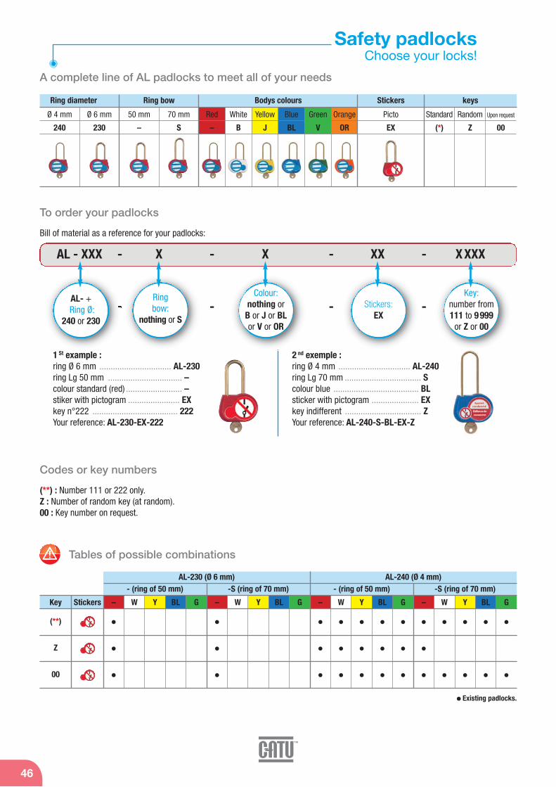
Red
–
White
B
Yellow
J
Blue
BL
Green
V
Orange
OR
46
Safety padlocksChoose your locks!
A complete line of AL padlocks to meet all of your needs
Tables of possible combinations
Codes or key numbers
Ring diameter
AL-230 (Ø 6 mm) AL-240 (Ø 4 mm)- (ring of 50 mm) -S (ring of 70 mm) - (ring of 50 mm) -S (ring of 70 mm)
Ring bow Bodys colours
Ø 4 mm
240
Ø 6 mm
230
50 mm
–
70 mm
S
– W Y BL GKey
(**)
Z
00
Stickers
(**) : Number 111 or 222 only.Z : Number of random key (at random).00 : Key number on request.
1 St example : ring Ø 6 mm ................................ AL-230ring Lg 50 mm ................................. –colour standard (red) ......................... –stiker with pictogram ....................... EXkey n°222 ...................................... 222Your reference: AL-230-EX-222
2 nd exemple : ring Ø 4 mm ................................ AL-240ring Lg 70 mm .................................. Scolour blue ...................................... BLsticker with pictogram ..................... EXkey indifferent .................................. ZYour reference: AL-240-S-BL-EX-Z
Existing padlocks.
To order your padlocks
AL - XXX - X - X - XX - X XXX
- - - - AL- + Ring Ø:
240 or 230
Ringbow:
nothing or S
Colour:nothing or B or J or BLor V or OR
Stickers:EX
Key:number from111 to 9 999
or Z or 00
Bill of material as a reference for your padlocks:
Stickers
Picto
EX
keys
Standard
(*)
Random
Z
Upon request
00
– W Y BL G – W Y BL G– W Y BL G

Locking and Signaling
Padlocks
47
Models with special symbols
Reference
AL-230-(**)-EX
AL-230-S-(**)-EX
AL-230-Z-EX
AL-230-S-Z-EX
AL-240-(**)-EX
AL-240-S-(**)-EX
AL-240-Z-EX
AL-240-S-Z-EX
50
70
50
70
50
70
50
70
6
6
6
6
4
4
4
4
204
214
204
214
192
198
192
198
gmm
mm
(**) Add the key numbers 111 or 222 only.
Ring
Colour models
Reference
AL-240-B-(**)-EX
AL-240-B-Z-EX
AL-240-B-00-EX
AL-240-S-B-(**)-EX
AL-240-S-B-00-EX
AL-240-J-(**)-EX
AL-240-J-Z-EX
AL-240-J-00-EX
AL-240-S-J-(**)-EX
AL-240-S-J-00-EX
AL-240-BL-(**)-EX
AL-240-BL-Z-EX
AL-240-BL-00-EX
AL-240-S-BL-(**)-EX
AL-240-S-BL-00-EX
AL-240-V-(**)-EX
AL-240-V-Z-EX
AL-240-V-00-EX
AL-240-S-V-(**)-EX
AL-240-S-V-00-EX
RingColour
50
50
50
70
70
50
50
50
70
70
50
50
50
70
70
50
50
50
70
70
4
4
4
4
4
4
4
4
4
4
4
4
4
4
4
4
4
4
4
4
White
White
White
White
White
Yellow
Yellow
Yellow
Yellow
Yellow
Blue
Blue
Blue
Blue
Blue
Green
Green
Green
Green
Green
192
192
192
198
198
192
192
192
198
198
192
192
192
198
198
192
192
192
198
198
gmm
mm
(**) Add the key numbers 111 or 222 only.
For all padlocks
Reference Characteristics
A-76230Additional key
(specify the number)
mmDiameter g Weightmm Total height
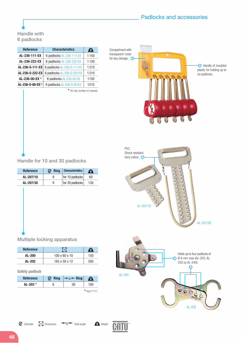
48
Padlocks and accessories
* 00: key number on request.
Compartment withtransparent coverfor key storage.
Handle with 6 padlocks
Handle of mouldedplastic for holding up tosix padlocks.
Reference Characteristics
AL-236-111-EX
AL-236-222-EX
AL-236-S-111-EX
AL-236-S-222-EX
AL-236-00-EX *
AL-236-S-00-EX *
6 padlocks AL-230-111-EX
6 padlocks AL-230-222-EX
6 padlocks AL-230-S-111-EX
6 padlocks AL-230-S-222-EX
6 padlocks AL-230-00-EX
6 padlocks AL-230-S-00-EX
1 150
1 150
1 210
1 210
1150
1210
g
Reference Ring Characteristics
AL-207/10
AL-207/30
9
9
for 10 padlocks
for 30 padlocks
60
130
g
Handle for 10 and 30 padlocks
PVC.Shock resistant.Ivory colour.
mm
Reference
AL-200
AL-202
100 x 60 x 10
165 x 50 x 12
150
200
g
Reference Ring
AL-203 * 6 50 180
gmm
Ringmm
Multiple locking apparatus
Holds up to four padlocks ofØ 6 mm max (AL-203, AL-230 ou AL-240).
Safety padlock
AL-207/10
AL-207/30
AL-200
AL-202
* Key n°111.
mm
mm Dimensionsmm
Diameter g Weightmm Total length
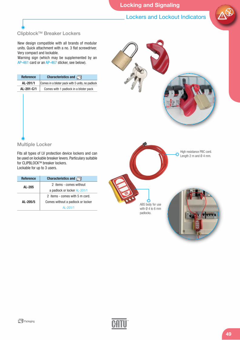
Locking and Signaling
Lockers and Lockout Indicators
49
ClipblockTM Breaker Lockers
Multiple Locker
New design compatible with all brands of modularunits. Quick attachment with a no. 3 flat screwdriver.Very compact and lockable.Warning sign (which may be supplemented by an AP-461 card or an AP-467 sticker, see below).
Reference Characteristics and
AL-201/1
AL-201-C/1
Comes in a blister pack with 5 units, no padlock
Comes with 1 padlock in a blister pack
Fits all types of LV protection device lockers and canbe used on lockable breaker levers. Particulary suitablefor CLIPBLOCKTM breaker lockers.Lockable for up to 3 users.
High resistance PBC cord. Length 2 m and Ø 4 mm.
Reference Characteristics and
AL-205
AL-205/5
2 items - comes without
a padlock or locker AL-201/1
2 items - comes with 5 m cord.
Comes without a padlock or locker
AL-201/1ABS body for usewith Ø 4 to 6 mmpadlocks.
Packaging

50
Warning signs
Warning signs
Special tool steel, oil-hardened.
AM-344-GB AM-345-GB AM-344/05 - AM-344
AM-49/… AM-41/… AM-467-GB
1
2
3
5
FIRST, SELECT THE RIGHT EQUIPEMENTS
EN 50110
LOCKEDAPPARATUS
FORBIDDENTO
OPERATE
+
+
++
Det
ex
3
T
MO-11000or
MO-11001
CG-10-B
MS-911
AL-230-GB
AL-318
AL-32/05
MP-42/11or
MP-42/16
LOCKEDAPPARATUS
FORBIDDENTO
OPERATE
4
DEAD WORKING LOW VOLTAGEFIVE GOLDEN RULES
4
1 Isolate the installationfrom sources of supply.
2 Lock the isolation devicesin the open position.
Check the absence of voltage.
3 Identify the work. 5 Show warm others. Protectthe work area from the closelive parts.
DRAW
ING
AP-499/1 AM-20-GB AP-510-BT-GB
Reference Type Colours
AM-344-GB aluminium 100 mm side black letters on yellow
AM-345-GB aluminium 100 mm side black letters on yellow
AM-467-GB aluminium Ø 80 mm white letterson red
AP-510-BT-GB plastic 297 x 210 mm golden rules
AM-344 aluminium 100 mm side black or yellow
AM-344/05 aluminium 50 mm side black or yellow
AM-49/1 aluminium 100 mm side black or yellow
AM-49/2 aluminium 200 mm side black or yellow
AM-41/1 aluminium 100 mm side black or yellow
AM-41/2 aluminium 200 mm side black or yellow
AM-20-GB aluminium 350 x 250 mm blue letters plain aluminium
AP-499/1 plastic Ø 100 mm white or red
mm Dimensions
AM-20-RM
AP-510-GB AM-7002
AM-215-RM
AM-282/2-RM
AM-61-GB AM-61-RMAL-53
ALU-METALTM AM-34/2 97
TM
AM-34/2
AP - 951/2 96
AP-951/2
TM
ALU-METALTM AM-33/3 97
AM-33/3AM-32/3
Substation signs
Specialized signs.
Reference Type Colours
AM-20-RM aluminium 350 x 500 mm blue letters on plain
aluminium
AM-61-GB aluminium 150 x 200 mm
AM-61-RM aluminium 150 x 200 mm
AM-215-RM aluminium 350 x 250 mm black on yellow
SF6 warning
AM-282/2-RM aluminium 200 x 60 mm
AM-7002 aluminium 300 x 200 mm black on yellow
AM-33/3 aluminium Ø 300 mm red-black on alu
AM-34/2 aluminium Ø 200 mm red-black on alu
AM-32/3 aluminium Ø 300 mm
AP-510-GB plastic 420 x 297 mm golden rules
AP-951/2 plastic 200 x 200 mm red on white
Reference mm
AL-53 650 x 350 on handle
Warning flags
Brightly colored ribbon.
For other models, please consult us.
mm
mm
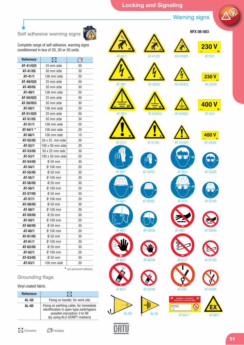
Self adhesive warning signs
Complete range of self adhesive, warning signs conditionned in box of 20, 30 or 50 units.
Reference mm
AT-41/025AT-41/05AT-41/1
AT-49/025AT-49/05AT-49/1
AT-50/025AT-50/053AT-50/1
AT-51/025AT-51/05AT-51/1
AT-64/1 *AT-66/1AT-52/05AT-52/1AT-53/05AT-53/1AT-54/05AT-54/1AT-55/05AT-55/1AT-56/05AT-56/1AT-57/05AT-57/1AT-58/05AT-58/1AT-59/05AT-59/1AT-60/05AT-60/1AT-61/05AT-61/1AT-62/05AT-62/1AT-63/05AT-63/1
25 mm side
50 mm side
100 mm side
25 mm side
50 mm side
100 mm side
25 mm side
50 mm side
100 mm side
25 mm side
50 mm side
100 mm side
100 mm side
100 mm side
50 x 25 mm side
100 x 50 mm side
50 x 25 mm side
100 x 50 mm side
Ø 50 mm
Ø 100 mm
Ø 50 mm
Ø 100 mm
Ø 50 mm
Ø 100 mm
Ø 50 mm
Ø 100 mm
Ø 50 mm
Ø 100 mm
Ø 50 mm
Ø 100 mm
Ø 50 mm
Ø 100 mm
Ø 50 mm
Ø 100 mm
Ø 50 mm
Ø 100 mm
Ø 50 mm
100 mm side
50
30
20
50
30
20
50
30
20
50
30
20
20
10
30
20
30
20
30
20
30
20
30
20
30
20
30
20
30
20
30
20
30
20
30
20
30
20
AT-51/025AT-51/05AT-51/1
AT-41/025AT-41/05AT-41/1
AT-49/025AT-49/05AT-49/1
AT-52/1
AT-52/05
AT-53/1
AT-53/05
AT-54/1 AT-54/05 AT-55/1 AT-55/05
AT-56/1 AT-56/05 AT-57/1 AT-57/05
AT-58/1 AT-58/05 AT-59/1 AT-59/05
AT-60/1 AT-60/05 AT-61/1 AT-61/05
AT-62/1 AT-62/05 AT-63/1 AT-63/05
AT-50/025AT-50/053AT-50/1
AT-66/1AT-64/1 *
* non-permanent adhesive.
Locking and Signaling
51
Warning signs
NFX 08-003
Packaging
Reference mm
AL-58
AL-60
Fixing on handle; for work site
Fixing on earthing cable; for immediateidentification in open-type switchgears
possible inscription: 0 to 99(by using ALU-SCRIPT markers)
Grounding flags
Vinyl coated fabric.
AL-58AL-60
mm Dimensions
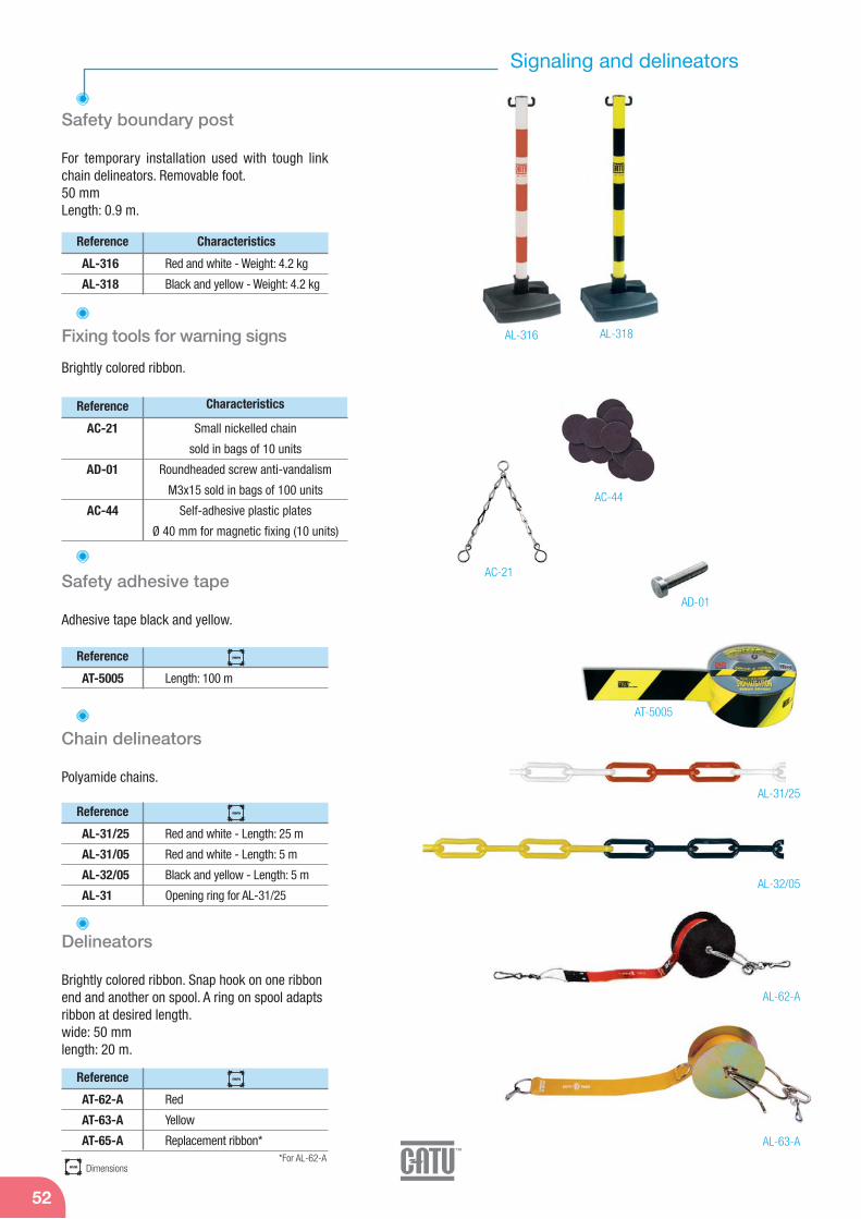
52
AL-62-A
AL-63-A
AL-32/05
AL-31/25
Safety adhesive tape
Reference
Adhesive tape black and yellow.
AT-5005 Length: 100 m
Chain delineators
Reference
Polyamide chains.
AL-31/25 Red and white - Length: 25 m
AL-31/05 Red and white - Length: 5 m
AL-32/05 Black and yellow - Length: 5 m
AL-31 Opening ring for AL-31/25
Delineators
Reference
Brightly colored ribbon. Snap hook on one ribbon end and another on spool. A ring on spool adapts ribbon at desired length.wide: 50 mmlength: 20 m.
AT-62-A Red
AT-63-A Yellow
AT-65-A Replacement ribbon*
Signaling and delineators
AL-316 AL-318
AD-01
AC-21
AC-44
Safety boundary post
Reference
For temporary installation used with tough linkchain delineators. Removable foot. 50 mmLength: 0.9 m.
Characteristics
AL-316 Red and white - Weight: 4.2 kg
AL-318 Black and yellow - Weight: 4.2 kg
Reference
AC-21
AD-01
AC-44
Small nickelled chain
sold in bags of 10 units
Roundheaded screw anti-vandalism
M3x15 sold in bags of 100 units
Self-adhesive plastic plates
Ø 40 mm for magnetic fixing (10 units)
Fixing tools for warning signs
Brightly colored ribbon.
Characteristics
mm Dimensions
mm
mm
mm
AT-5005
*For AL-62-A
Voltage Detector 54
Phase rotation indicator 58
Safety test probes and accessories 59
Installation Controller 61
Testers 64
Multimeters 65
LV test and measurement
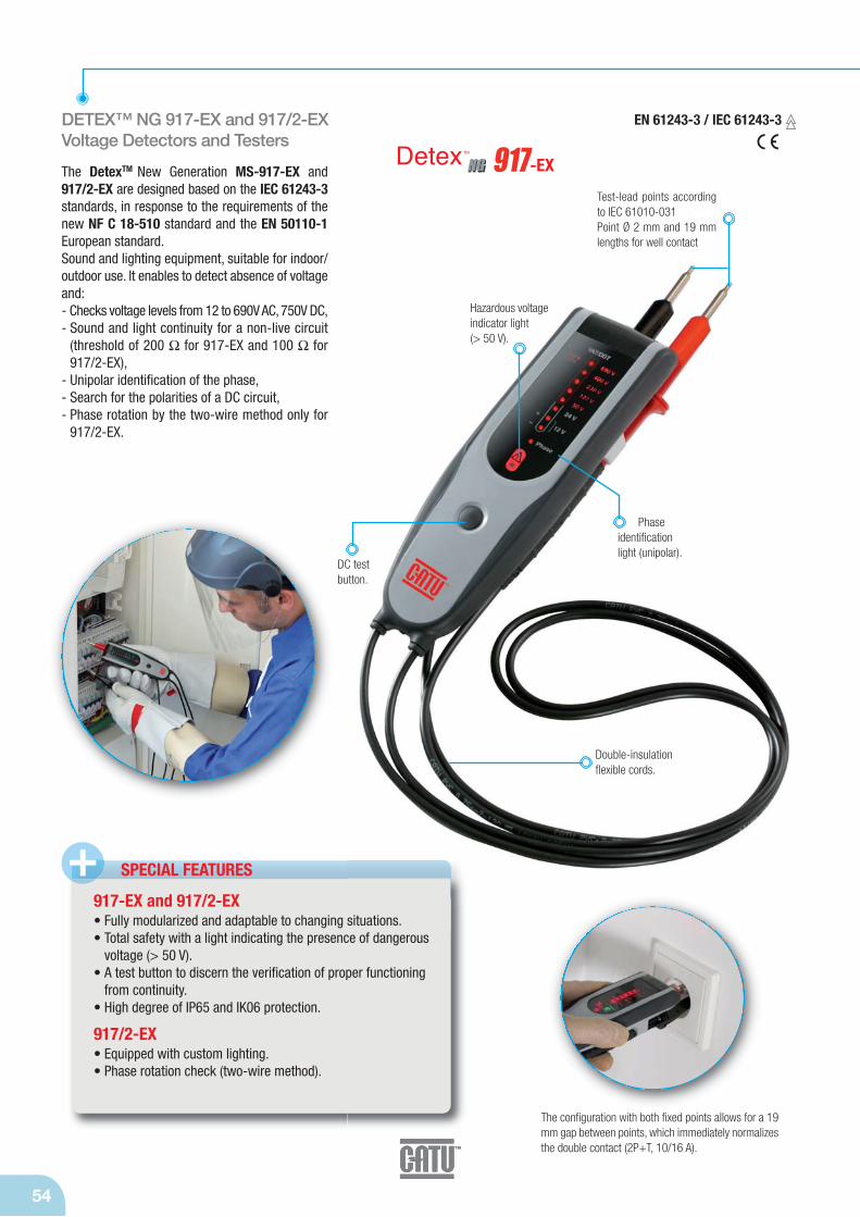
54
DETEX™ NG 917-EX and 917/2-EXVoltage Detectors and Testers
The DetexTM New Generation MS-917-EX and917/2-EX are designed based on the IEC 61243-3standards, in response to the requirements of thenew NF C 18-510 standard and the EN 50110-1European standard.Sound and lighting equipment, suitable for indoor/outdoor use. It enables to detect absence of voltageand:- Checks voltage levels from 12 to 690V AC, 750V DC,- Sound and light continuity for a non-live circuit
(threshold of 200 Ω for 917-EX and 100 Ω for917/2-EX),
- Unipolar identification of the phase,- Search for the polarities of a DC circuit,- Phase rotation by the two-wire method only for
917/2-EX.
SPECIAL FEATURES +917-EX and 917/2-EX• Fully modularized and adaptable to changing situations.• Total safety with a light indicating the presence of dangerous
voltage (> 50 V).• A test button to discern the verification of proper functioning
from continuity.• High degree of IP65 and IK06 protection.
917/2-EX• Equipped with custom lighting.• Phase rotation check (two-wire method).
Test-lead points accordingto IEC 61010-031Point Ø 2 mm and 19 mmlengths for well contact
DC test button.
Double-insulationflexible cords.
Hazardous voltageindicator light (> 50 V).
Phase identification light (unipolar).
The configuration with both fixed points allows for a 19mm gap between points, which immediately normalizesthe double contact (2P+T, 10/16 A).
EN 61243-3 / IEC 61243-3
-EX

LV Test and measurement
55
Voltage Detector
Reference
MS-917-EX *
MS-917/2-EX *
200
100
– –
Selections and Characteristics:
Cat=
g
Voltage12-690 V AC12-750 V DC
50/60 Hz+/- 10 % Continuity
IP65 Protection
IK06
Category IV600 V
Operations -15 to +55 °C
(class N)
2 AAA batteries
1.5 V
Phase rotation direction
Lighting unit. 210
Suitable forstandard 2P+T.
19 mmClass II
Dangerous voltagelight (> 50 V).
Phase identificationlight (unipolar).
Phase rotation detection check(two-wire method)
Multifunctional light12 V / + range12 V / - range
Voltage light.for 24 to 690 V AC(750 DC)
MS-917/2storage configuration.
M-87369Carrying bag.
M-952325Board hanger providedon the back of the device.
Touch-key unlockingcontrol.
Lighting unit.
Accessories
Reference
M-87369
M-952325
Carrying bag *
Board hanger *
Characteristics
MS-917/2-EX Front Panel
* Ordered separately.
* Supplied without accessories.
-EX

56
DETEXTM NG 920 Voltage Detector and Tester
The DetexTM New Generation MS-920 is designedbased on IEC 61243-3 rates, in response to the re-quirements of the new NF C 18-510 standard andthe EN 50110-1 European standard.Sound and lighting equipment, suitable for indoor/outdoor use. It enables to detect absence of vol-tage and:- Check of voltage levels > 50 V DC and AC,- Up to 690 V AC and 750 V DC,- Continuity sound control for a non-live (< 100 Ω),- Measure of non-live continuity from 100 to 1,000 Ω,- Unipolar identification of the phase,- Search for the polarities of a DC circuit,- Phase rotation check (two-wire method).
EN 61243-3 / IEC 61243-3
DC test button.
Double-insulationflexible cords.
SPECIAL FEATURES+• Three-digit digital display RED and BLUE).• Measure of AC and DC voltage.• Measure of continuity in Ω (up to 1000 Ω).• Fully modularized and adaptable to changing situations.• Total safety with a light indicating the presence of dangerous
voltage (> 50 V).• A test button to discern the verification of proper functioning
and continuity (threshold of 100 Ω).• IP2X touch key "Touch" functionality.• High degree of IP65 and IK06 protection.• Phase rotation check (two-wire method).• Equipped with custom lighting.
Three digit colourLCD screen display.
Indicator lightwhen voltage > 50 V.
Unlockingcontrol.
The configuration with both fixed points allows for a 19 mmgap between points, which immediately normalizes thedouble contact (2P+T, 10/16 A).
-EXTest-lead points accordingto IEC 61010-031Point Ø 2 mm and 19 mmlengths for well contact.
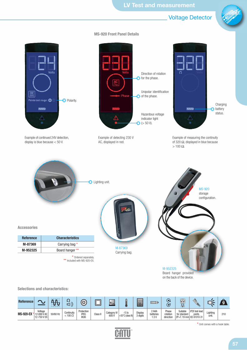
LV Test and measurement
57
Reference
MS-920-EX *
Selections and characteristics:
g
Voltage12-690 V AC12-750 V DC
50/60 Hz Continuity< 100 Ω
ProtectionIP65IK06
Category IV600 V
-15 to+55°C (class N)
2 AAA batteries
1.5 V
Phase rotation direction
IP2X test-leadpoints.
IEC 61010-31
Lighting unit. 210
Suitable for standard
2P+T. 19 mmClass II
Accessories
Reference
M-87369
M-952325
Carrying bag *
Board hanger **
Characteristics
Cat
=
* Ordered separately.** Included with MS-920-EX.
* Unit comes with a hook table.
M-87369Carrying bag.
Polarity.
MS-920 Front Panel Details
Hazardous voltageindicator light (> 50 V).
Direction of rotationfor the phase.
Unipolar identificationof the phase.
Chargingbatterystatus.
Example of continued 24V detection,display is blue because < 50 V.
Example of detecting 230 VAC, displayed in red.
Example of measuring the continuityof 320 Ω, displayed in blue because> 100 Ω.
Lighting unit.
Display3 digits
888
MS-920storage configuration.
M-952325Board hanger providedon the back of the device.
Voltage Detector
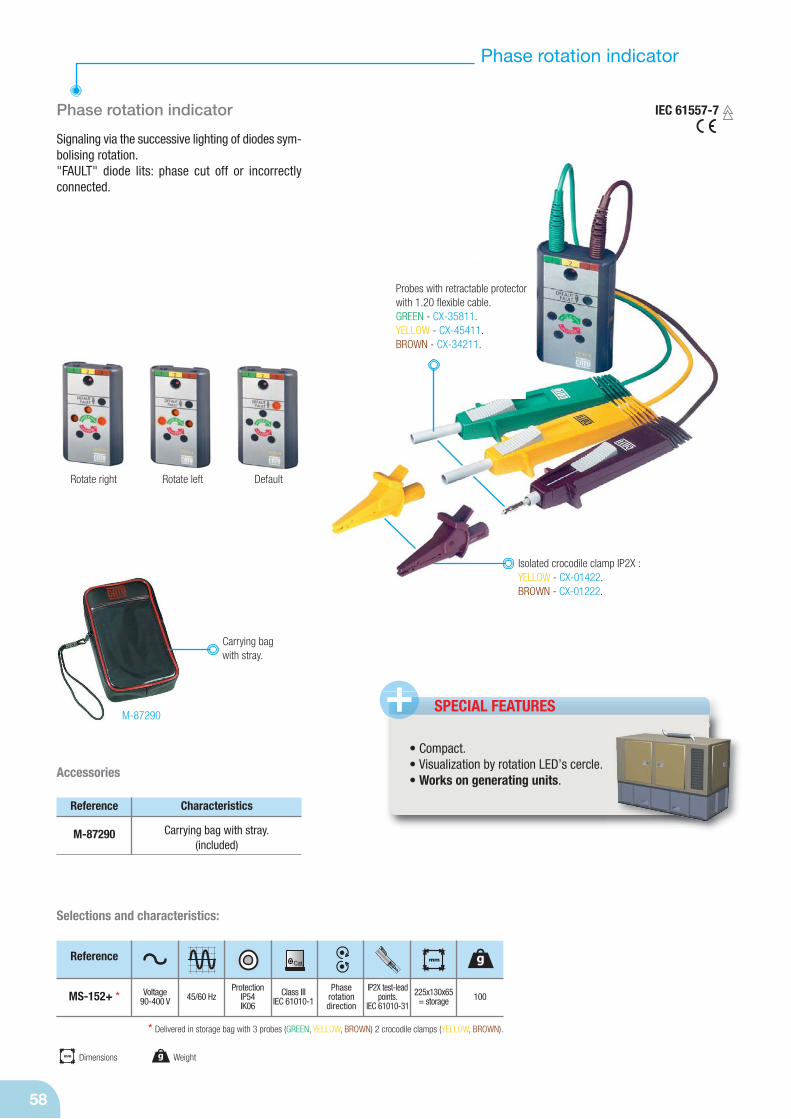
Phase rotation indicator
58
Phase rotation indicator
Signaling via the successive lighting of diodes sym-bolising rotation."FAULT" diode lits: phase cut off or incorrectlyconnected.
Reference
MS-152+ *
Selections and characteristics:
g
Voltage90-400 V 45/60 Hz
ProtectionIP54IK06
Class IIIIEC 61010-1
Phase rotation direction
IP2X test-leadpoints.
IEC 61010-31100
mm
225x130x65= storage
Accessories
Reference
M-87290
Characteristics
Carrying bag with stray.(included)
Rotate right Rotate left Default
IEC 61557-7
Isolated crocodile clamp IP2X :YELLOW - CX-01422.BROWN - CX-01222.
Probes with retractable protectorwith 1.20 flexible cable.GREEN - CX-35811.YELLOW - CX-45411.BROWN - CX-34211.
SPECIAL FEATURES+
Cat
* Delivered in storage bag with 3 probes (GREEN, YELLOW, BROWN) 2 crocodile clamps (YELLOW, BROWN).
Carrying bagwith stray.
M-87290
mm Dimensions g Weight
• Compact.• Visualization by rotation LED’s cercle.• Works on generating units.
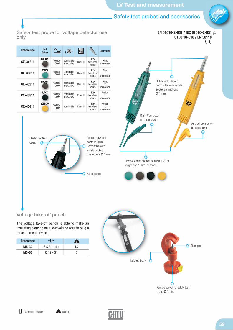
LV Test and measurement
59
Safety test probes and accessories
Safety test probe for voltage detector useonly
EN 61010-2-031 / IEC 61010-2-031UTEC 18-510 / EN 50110
Hand-guard.
Access downhole depth 26 mm.Compatible withfemale socket connections Ø 4 mm.
Elastic contactcage.
Reference
CX-34211
CX-35811
CX-45211
CX-45511
CX-45411
A Cat
Voltage1000 V
Voltage1000 V
Voltage1000 V
Voltage1000 V
Voltage1000 V
admissiblemax. 20 A
admissiblemax. 20 A
admissiblemax. 20 A
admissiblemax. 20 A
admissible
Class III
Class III
Class III
Class III
Class III
Rightundeceived
Rightno
undeceived
Rightno
undeceived
Angledno
undeceived
Angledno
undeceived
IP2X test-leadpoints.
IP2X test-leadpoints.
IP2X test-leadpoints.
IP2X test-leadpoints.
IP2X test-leadpoints.
ConnectorUnit Colour
Retractable sheathcompatible with femalesocket connections Ø 4 mm.
Flexible cable, double isolation 1.20 mlenght and 1 mm2 section.
Angled connectorno undeceived.
Right Connectorno undeceived.
BROWN
GREEN
BROWN
BLACK
YELLOW
Voltage take-off punch
The voltage take-off punch is able to make an insulating piercing on a low voltage wire to plug ameasurement device.
Isolated body.
Steel pin.
Female socket for safety testprobe Ø 4 mm.
Reference
MS-62
MS-63
Ø 5.6 - 14.4
Ø 12 - 31
15
5
mmg
g Weightmm
Clamping capacity
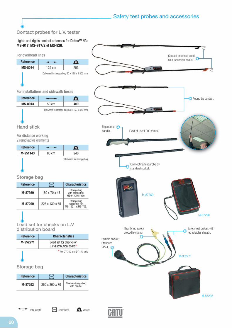
Safety test probes and accessories
60
Contact probes for L.V. tester
Lights and rigids contact antennas for DetexTM NG : MS-917, MS-917/2 et MS-920.
For installations and sidewalk boxes
For overhead lines
Reference
MS-8014 125 cm 755
g
Reference
MS-8013 50 cm 400
g
Delivered in storage bag 50 x 130 x 1 300 mm.
Delivered in storage bag 50 x 150 x 470 mm.
Reference
M-951143 80 cm 240
g
Delivered in storage bag.
Contact antennas usedas suspension hooks.
Round tip contact.
Hand stick
For distance working2 removables elements
Ergonomichandle. Field of use:1 000 V max.
M-87290
Storage bagReference Characteristics
M-87369
M-87290
180 x 70 x 45
225 x 130 x 65
mm
Storage bag with seatbelt for
MS-917, MS-920.
Storage bag with stray for
MS-152+ et MS-703.
M-87369
mm Dimensions g Weightmm Total length
Lead set for checks on L.V distribution board
Reference
M-952271 Lead set for checks on L.V distribution board *
Characteristics
* For DT-300 and DT-170 only.
Female socketStandard2P+T.
Heartbring safetycrocodile clamp.
Safety test probes withretractables sheath.
Storage bag
Reference Characteristics
M-87292 250 x 200 x 70
mm
Flexible storage bagwith handle.
M-87292
M-952271
Connecting test probe bystandard socket.
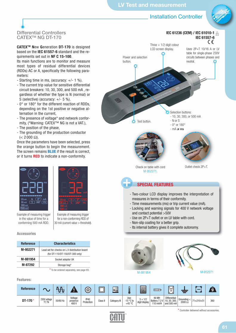
LV Test and measurement
61
Installation Controller
Reference
DT-170 *
Features:
g
230V voltageTT, TN 50/60 Hz
Voltage presence
400 V
Use: -15 °C to +45 °C
IP40 Protection Category III Grounding <
2000 Ω 3603 + 1/2 digit displayClass II
Differential Controllers CATEXTM NG DT-170
CATEXTM New Generation DT-170 is designedbased on the IEC 61557-6 standard and the re-quirements set out in NF C 15-100.Its main functions are to monitor and measuremost types of residual differential devices(RDDs) AC or A, specifically the following para-meters:- Starting time in ms, (accuracy: +/- 1 %).- The current trip value for sensitive differential
circuit breakers: 10, 30, 300, and 500 mA , re-gardless of whether the type is N (normal) orS (selective) (accuracy: +/- 5 %).
- 0° or 180° for the different reaction of RDDs,depending on the 1st positive or negative al-ternation in the current,
- The presence of voltage* and network confor-mity, (*Warning: CATEX™ NG is not a VAT.),
- The position of the phase,- The grounding of the production conductor
(< 2 000 Ω).Once the parameters have been selected, pressthe orange button to begin the measurement.The screen remains BLUE if the result is correct,or it turns RED to indicate a non-conformity.
Selection buttons:- 10, 30, 300, or 500 mA- N or S- 0° or 180°- mA or ms
Power and selectionbutton.
Test button.
Uses 2P+T 10/16 A or LVtable for single-phase 230Vcircuits between phases andneutral.
NI-MH Battery 7.2 V110 mA/H
Example of measuring triggerin the value of time for a
conforming 500 mA RDD.
Example of measuring trigger for a non-conforming RDD of
30 mA (current value > threshold).
SPECIAL FEATURES+- Two-colour LCD display improves the interpretation of
measures in terms of their conformity.- Time measurements (ms) or trip current value (mA).- Locking and warning signals for 400 V network voltage
and contact potential >50V- Use on 2P+T outlet or on LV table with cord.- Non-slip coating for a better grip.- Its internal battery gives it complete autonomy.
Outlet check 2P+T.Check on table with cordM-952271.
IEC 61236 (CEM) / IEC 61010-1IEC 61557-6
mm
71x210x51
* Controller delivered without accessories.
Three + 1/2 digit colourLCD screen display.
Differential:10, 30, 300,and 500 mA
Cat888 DDR
mA
M-952271M-881954
Accessories
Reference
M-952271
M-881954
M-87292
Lead set for checks on L.V distribution board (for DT-110/DT-150/DT-300 only)
Socket adaptor UK
Storage bag*
Characteristics
* To be ordered separately, see page 65.
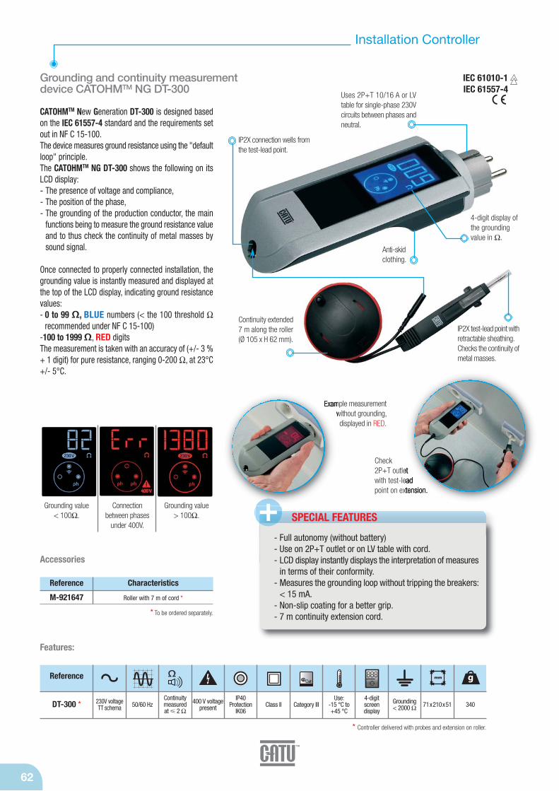
62
Grounding and continuity measurementdevice CATOHMTM NG DT-300
CATOHMTM New Generation DT-300 is designed basedon the IEC 61557-4 standard and the requirements setout in NF C 15-100.The device measures ground resistance using the "defaultloop" principle.The CATOHMTM NG DT-300 shows the following on itsLCD display:- The presence of voltage and compliance,- The position of the phase,- The grounding of the production conductor, the main
functions being to measure the ground resistance valueand to thus check the continuity of metal masses bysound signal.
Once connected to properly connected installation, thegrounding value is instantly measured and displayed atthe top of the LCD display, indicating ground resistancevalues:- 0 to 99 Ω, BLUE numbers (< the 100 threshold Ω
recommended under NF C 15-100)-100 to 1999Ω, RED digitsThe measurement is taken with an accuracy of (+/- 3 %+ 1 digit) for pure resistance, ranging 0-200 Ω, at 23°C+/- 5°C.
Uses 2P+T 10/16 A or LVtable for single-phase 230Vcircuits between phases andneutral.
Anti-skid clothing.
4-digit display ofthe groundingvalue in Ω.
Installation Controller
IEC 61010-1IEC 61557-4
Features:
Continuitymeasured at 2 Ω
Grounding value < 100Ω.
Connection between phases
under 400V.
Grounding value > 100Ω.
Check2P+T outletwith test-leadpoint on extension.
Example measurementwithout grounding,displayed in RED.
IP2X connection wells fromthe test-lead point.
Reference
DT-300 *
Cat g
230V voltageTT schema 50/60 Hz 400 V voltage
present
Use: -15 °C to +45 °C
IP40Protection
IK06Category III Grounding
< 2000 Ω 3404-digit screen display
Class II
888 mm
71x210x51
IP2X test-lead point withretractable sheathing.Checks the continuity ofmetal masses.
SPECIAL FEATURES
- Full autonomy (without battery)- Use on 2P+T outlet or on LV table with cord.- LCD display instantly displays the interpretation of measures
in terms of their conformity.- Measures the grounding loop without tripping the breakers:
< 15 mA.- Non-slip coating for a better grip.- 7 m continuity extension cord.
Continuity extended7 m along the roller(Ø 105 x H 62 mm).
* Controller delivered with probes and extension on roller.
Reference
M-921647 Roller with 7 m of cord *
Characteristics
* To be ordered separately.
Accessories
+

LV Test and measurement
63
Installation Controller
Insulation controller
NF C 15-100 recommends periodically checkinginsulation resistance. Insulation resistance ismeasured between each active conductor and theground (when not live). Its value should be 500 kΩfor a DC testing voltage of 500 V.The DT-500 is a specially designed device forquickly, easily, and safely measuring insulation resistance.It provides a safety system that prevents a measu-rement when connected to a live installation.Measures insulation resistance below 500 V.
The insulation resistance value is indicated by illu-minating a light:- RED for values including 0, 300, 400 kΩ.- GREEN for values including 500, 600, 700, 800,
900, 1 000 kΩ and∞.
IP2X test-lead point BLUE(neutral) independent andconnected by a safetyterminal.
IP2X test-leadpoint RED.
IP2X test-lead pointYELLOW/GREEN (ground).
3 large opening alligator clips:RED, YELLOW/ GREEN,BLUE.
The DT-500 comes with abelt clip and areas wheretest-lead points can be stored.
The DT-500 can bypass the phase andneutral in order to protect sensitiveequipment (electronics, computers, etc.).
Test button for measuringand self-testing.
Battery statusindicator light.
Insulated resistancediodes.
500 V test indicatorlight.
Default blinking light.
IEC 61010-1IEC 61557-2
Features:
Reference
DT-500 *
Cat g
Output voltage
< 500 V DC from 0 to ∞
Use: 15 °C to +45 °C
IP54 Protec-tionIK06
Category IIIIEC 61010-1
600 with batteries andaccessories
Class II
500 V
+-mm
mesuresΩ
213x75x46
* Delivered with 3 test probes, 3 crocodiles safety clamps and batteries.
IP2Xtest-endpoints
4 LR6 batteries
Accessories
Reference
M-951981
M-87292
Characteristics
* To be ordered separately.
1 m insulationcable.
Replacement blue test-lead point *
Storage case *
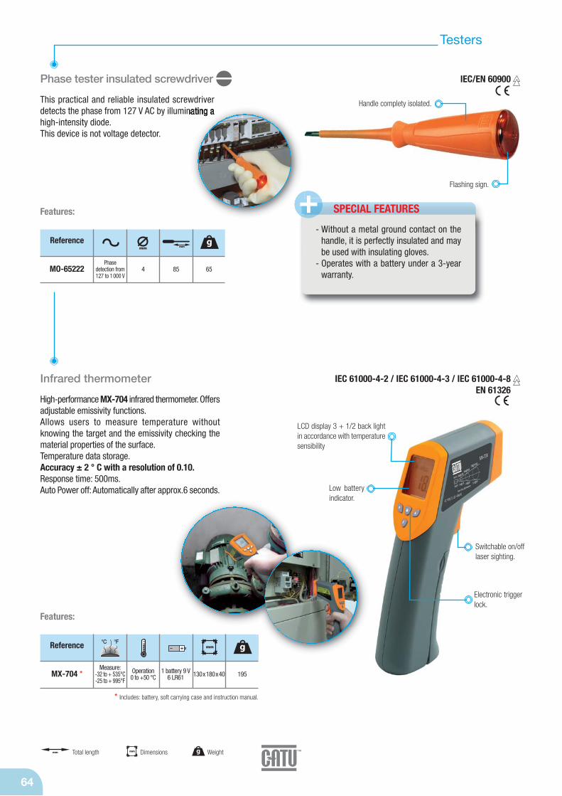
Testers
64
mm Dimensions g Weightmm Total length
Phase tester insulated screwdriver
This practical and reliable insulated screwdriverdetects the phase from 127 V AC by illuminating ahigh-intensity diode.This device is not voltage detector.
Flashing sign.
Handle complety isolated.
SPECIAL FEATURES +- Without a metal ground contact on the
handle, it is perfectly insulated and maybe used with insulating gloves.
- Operates with a battery under a 3-yearwarranty.
Reference
MO-65222
g
Phase detection from127 to 1000 V
65
mm mm
4 85
Features:
IEC/EN 60900
Infrared thermometer
High-performance MX-704 infrared thermometer. Offersadjustable emissivity functions.Allows users to measure temperature withoutknowing the target and the emissivity checking thematerial properties of the surface.Temperature data storage.Accuracy ± 2 ° C with a resolution of 0.10.Response time: 500ms.Auto Power off: Automatically after approx.6 seconds.
IEC 61000-4-2 / IEC 61000-4-3 / IEC 61000-4-8EN 61326
Low batteryindicator.
Electronic triggerlock.
Switchable on/off laser sighting.
LCD display 3 + 1/2 back lightin accordance with temperaturesensibility
Reference
MX-704 *
g
Operation0 to +50 °C 195
mm
130x180x40
* Includes: battery, soft carrying case and instruction manual.
°C °F
1 battery 9 V 6 LR61
Features:
Measure:-32 to + 535°C-25 to + 995°F

LV Test and measurement
65
1 thermometric probe
Multimeters
65
Digital multimeter
The MX-701 is a highly reliable 3-1/2 digit digitalmultimeter with automatic measuring range selection.It can measure direct and alternating voltage, AC and DC, resistance, capacity, temperature, and it cantest the diodes and open circuit (sound).
LCD display 3 +1/2 back light.
Voltage200 mV to
600 V AC / DC
75x158x35
* Delivered with 2 test probes or flexible cable, 2 thermometric probes, 2 crocodile clamps, batteries and storage bag.
Features:
MX-701 * 40 - 400 HzResistance200 Ω to 20 MΩ
Category III600 V
Capacity 20 nF to 1 000 μF
2 probes inaccessories 200Class III
Screendisplay
3 + 1/2 digits
Reference AmesuresΩ Cat
°C °F 888 mm gμF
Use:0 °C to+40 °C
Measure:-20 to
+1000°C0 to +1800°F
3 AAA1.5 V
batteries
Intensity200 μA to 10 AAC / DC
* Delivered with 2 test probes on flexibles cable, 1 thermometric probe, batteries and storage bag.
Features:
MX-702 *
ReferencemesuresΩ mm g
Indication of Lowbattery Level onscreen.
Selectionbutton.
Two crocodileclamps.
Digital clamp multimeter
The MX-702 is a compact 3-1/2 digit digital multi-meter with a clamp and automatic measuringrange selection.It can measure direct and alternating voltage, ACand DC voltage and AC curent, resistance, diodes,continuity, and temperature. It automatically indi-cates the polarity and overrange: OL or -OL.
2 thermometric probes.
2 probeswith angledsocket.
LCD display 3 +1/2 back light.
Max. measurableconductor: Ø 30 mm.Jaw opening capability: Ø 36 mm.Sensor: clamp-shapetransformer for AC mea-surement-
- Low batteryindication
mm Dimensions g Weight
2 probeswith angledsocket
A Cat
°C °F 888
Voltage 2 to 600 V AC
0.2 to 600 V DC70x190x3840 - 400 Hz
Resistance200 Ω to 20 MΩ
Use:0 °C to+40 °C
Category III600 V
Continuity "buzzer"< 50 Ω
2 probes inaccessories 220Class III
Screendisplay
3 + 1/2 digits
2 AAA1.5 V
batteries
Intensity2 to 600 A
AC
Measure:-40 to
+1000°C-40 to +1832°F
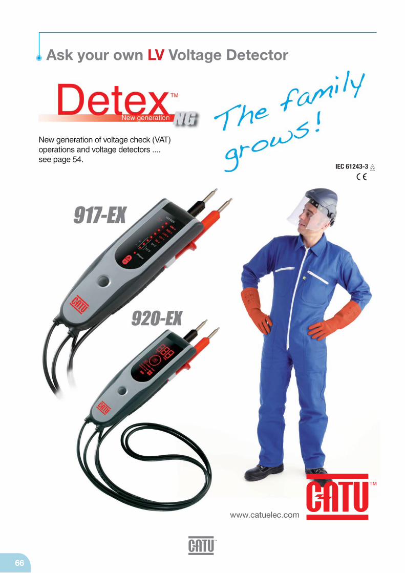
66
www.catuelec.com
Ask your own LV Voltage Detector
New generation of voltage check (VAT)operations and voltage detectors .... see page 54.
IEC 61243-3

Overhead bare 68
Overhead insulating 69
LV Cabinets 70
Consumer unit 71
LV earthing systems
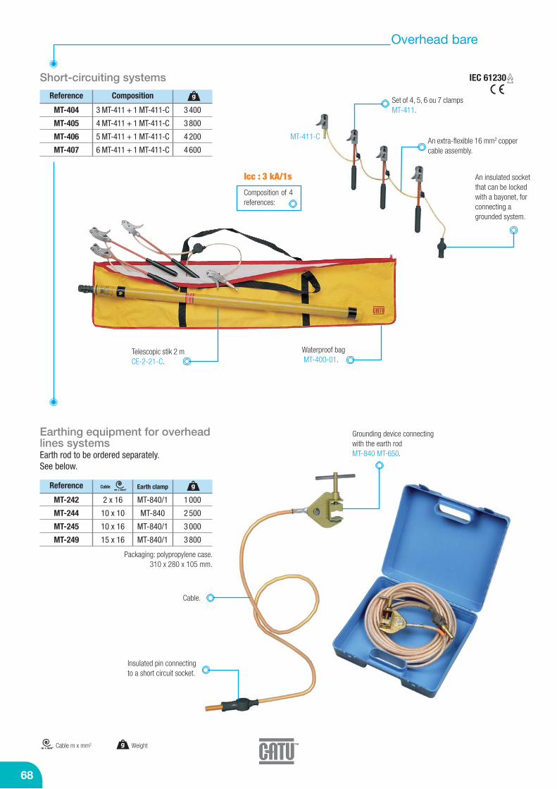
68
Overhead bare
Short-circuiting systems
Reference
MT-404
MT-405
MT-406
MT-407
3 MT-411 + 1 MT-411-C
4 MT-411 + 1 MT-411-C
5 MT-411 + 1 MT-411-C
6 MT-411 + 1 MT-411-C
3 400
3 800
4 200
4 600
gSet of 4, 5, 6 ou 7 clampsMT-411.
Waterproof bagMT-400-01.
Telescopic stik 2 mCE-2-21-C.
An extra-flexible 16 mm2 coppercable assembly.
An insulated socketthat can be lockedwith a bayonet, forconnecting agrounded system.
Icc : 3 kA/1s
Composition
Composition of 4references:
Earthing equipment for overheadlines systemsEarth rod to be ordered separately.See below.
Cable.
Insulated pin connecting to a short circuit socket.
Grounding device connectingwith the earth rodMT-840 MT-650.
g Weightm x mm2 Cable m x mm2
Reference
MT-242
MT-244
MT-245
MT-249
2 x 16
10 x 10
10 x 16
15 x 16
MT-840/1
MT-840
MT-840/1
MT-840/1
1 000
2 500
3 000
3 800
m x mm2gEarth clamp Cable
Packaging: polypropylene case. 310 x 280 x 105 mm.
MT-411-C
IEC 61230

LV earthing systems
69
Overhead insulating
Lowlock system IEC 61230
Reference CompositionRating g
5 MT-616/1-03 contact clamps on handles (I = 0.35 m each) 4 braids of M-24-35 copper
cable (1.00 m) 1 M-87-153 carrying bag 250 x 85 x 750 mm
For conductors 3 to 21 mm Ø.With clamps type “snap-on/screw-on”.Connecting cables: 35 mm2 copper.Short-circuiting and earthing systems
7.5MT-615/1-7,5 3 000
5 MT-616/1-03 contact clamps on handles4 braids of M-24-35 copper cable (1.00 m)1 braid of M-24-35 copper cable (7.00 m)
1 MT-840/1 earth clamp
7.5MT-615/2-7,5 6 500
Short-circuiting systems
MT-222
Reference
MT-205
MT-206
MT-207
5
6
7
1 100
1 500
1 900
gSocket
Reference
MT-222
MT-223
10 x 25
35 x 70
Earthing equipment
Equipment includes either 5 or 6 copper-aluminiumalloy stubs
285390285
118
800
800
Packaging: polypropylene case. 234 x 215 x 75 mm.
Upon request, ability to connect witha male socket.
Set of 4, 5, 6 ou 7clamps.
Connector for conductor MT-222 or MT-223, see below, to ordered separatly.
An extra-flexible16 mm2 coppercable assembly.
Reference
MT-650 1 m 2 200
g
m x mm2
A connector for conductors
To be ordered in addition to short circuit and grounding equipment.
Earth rodEarthing equipment with bayonet splicing for over-head lines systems
Galvanized steel.Hexagonal 18 mmper side.
Icc : 4 kA/1s
Composition of 3references:
g Weight
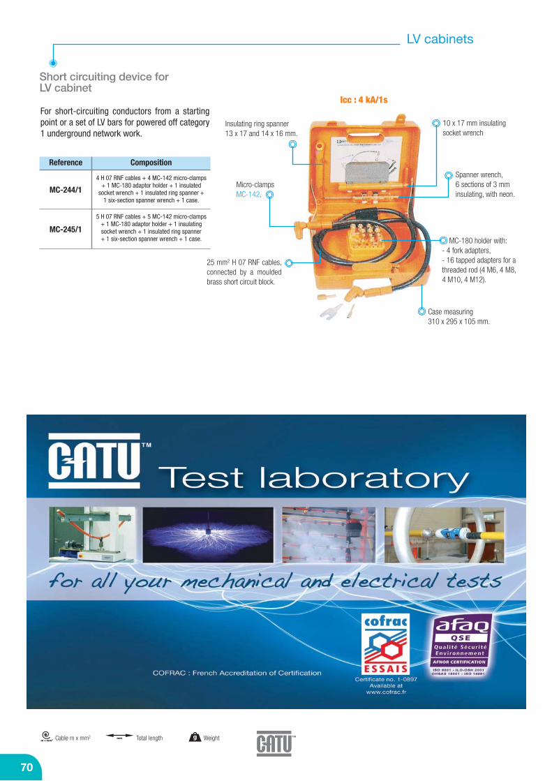
70
g Weightmmm x mm2 Total lengthCable m x mm2
LV cabinets
Short circuiting device for LV cabinet
Reference
MC-244/1
MC-245/1
Composition
Icc : 4 kA/1sFor short-circuiting conductors from a startingpoint or a set of LV bars for powered off category1 underground network work.
4 H 07 RNF cables + 4 MC-142 micro-clamps+ 1 MC-180 adaptor holder + 1 insulated
socket wrench + 1 insulated ring spanner + 1 six-section spanner wrench + 1 case.
5 H 07 RNF cables + 5 MC-142 micro-clamps+ 1 MC-180 adaptor holder + 1 insulatingsocket wrench + 1 insulated ring spanner+ 1 six-section spanner wrench + 1 case.
25 mm2 H 07 RNF cables,connected by a mouldedbrass short circuit block.
Micro-clampsMC-142.
MC-180 holder with:- 4 fork adapters,- 16 tapped adapters for athreaded rod (4 M6, 4 M8, 4 M10, 4 M12).
10 x 17 mm insulatingsocket wrench
Insulating ring spanner13 x 17 and 14 x 16 mm.
Spanner wrench, 6 sections of 3 mminsulating, with neon.
Case measuring 310 x 295 x 105 mm.
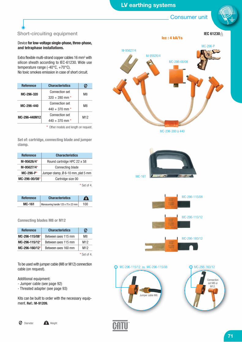
LV earthing systems
71
Consumer unit
Set of: cartridge, connecting blade and jumperclamp.
To be used with jumper cable (M8 or M12) connectioncable (on request).
Additional equipment:- Jumper cable (see page 92)- Threated adapter (see page 93)
Kits can be built to order with the necessary equip-ment. Ref.: M-91209.
MC-296-115/08
MC-296-115/12
MC-296-160/12
Short-circuiting equipment
Reference
MC-296-320
MC-296-440
MC-296-440M12
Connection set
320 + 280 mm *
Connection set
440 + 370 mm *
Connection set
440 + 370 mm *
M8
M8
M12
Characteristicsmm
Reference
M-95626/4*
M-95627/4*
MC-296-P*
MC-296-00/08*
Round cartridge HPC 22 x 58
Connecting blade
Jumper clamp, Ø 6-10 mm, plat 5 mm
Cartridge size 00
Characteristics
Device for low-voltage single-phase, three-phase,and tetraphase installations.
Extra flexible multi-strand copper cables 16 mm2 withsilicon sheath according to IEC-61230. Wide usetemperature range (-40°C, +70°C).No toxic smokes emission in case of short circuit.
* Other models and length on request.
* Set of 4.
* Set of 4.
M-95627/4
M-95626/4
MC-296-00/08
MC-296-P
MC-296-280 à 440
Reference
MC-161 Manœuvring handle 125 x 75 x 23 mm 100
gCharacteristics
Connecting blades M8 or M12
Reference
MC-296-115/08*
MC-296-115/12*
MC-296-160/12*
Between axes 115 mm
Between axes 115 mm
Between axes 160 mm
M8
M12
M12
Characteristics
MC-161
MC-296-115/12 ou MC-296-115/08 MC-296-160/12
Jumper cable M8.
Connectionset M8 or
M12.
mm
Icc : 4 kA/1s
g Weightmm
Diameter
IEC 61230

Your major supplier forall your electrical safety equipment needs
Just contact us !
Insulated tools 74
Tool sets 88
Jumper clamps, cables and accessories 91
Cover-up equipment 94
Insulating sticks 96
Cable identifier 97
LV Live working tools
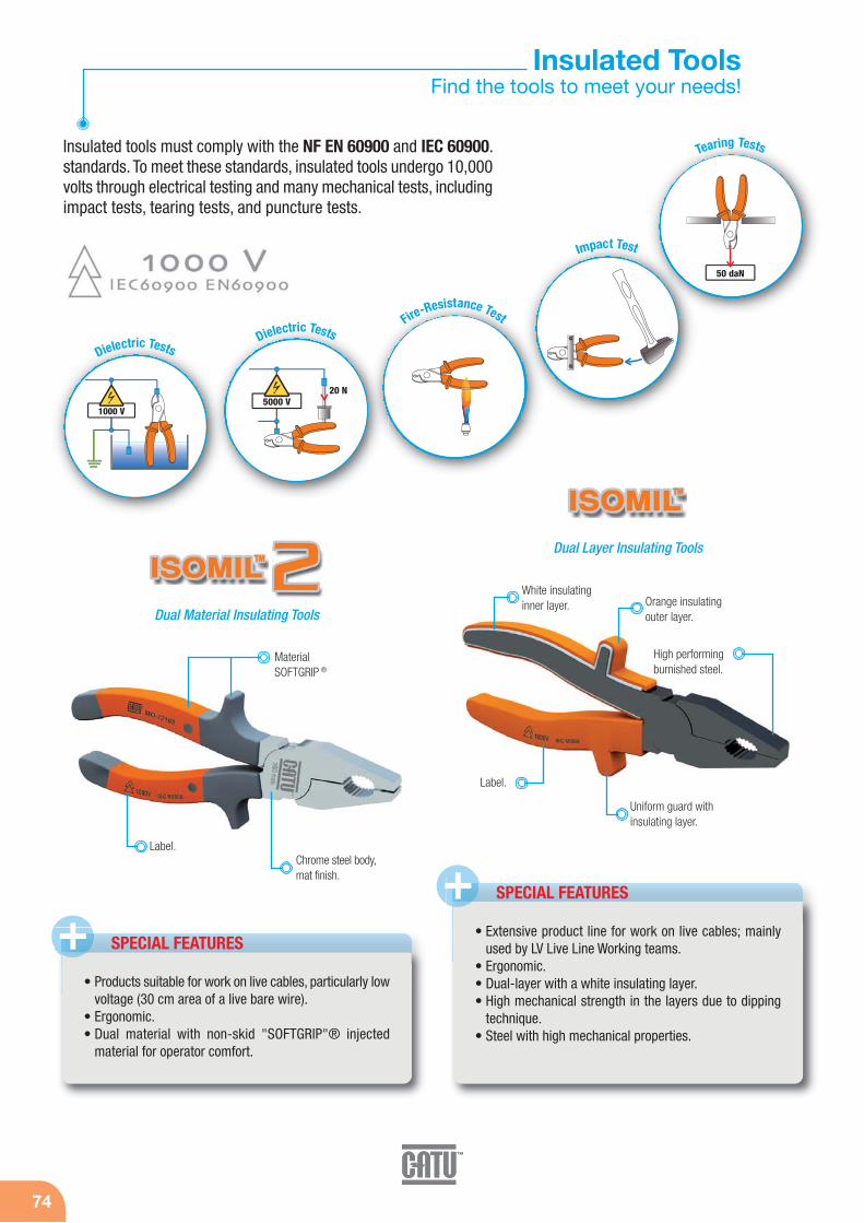
74
Insulated ToolsFind the tools to meet your needs!
Insulated tools must comply with the NF EN 60900 and IEC 60900.standards. To meet these standards, insulated tools undergo 10,000volts through electrical testing and many mechanical tests, includingimpact tests, tearing tests, and puncture tests.
Dual Layer Insulating Tools
Dual Material Insulating Tools
SPECIAL FEATURES+
Label.
Label.
Uniform guard withinsulating layer.
MaterialSOFTGRIP ®
White insulatinginner layer. Orange insulating
outer layer.
• Products suitable for work on live cables, particularly lowvoltage (30 cm area of a live bare wire).
• Ergonomic.• Dual material with non-skid "SOFTGRIP"® injected
material for operator comfort.
• Extensive product line for work on live cables; mainlyused by LV Live Line Working teams.
• Ergonomic.• Dual-layer with a white insulating layer.• High mechanical strength in the layers due to dipping
technique.• Steel with high mechanical properties.
20 N5000 V
50 daN
1000 V
Dielectric TestsDielectric Tests
Fire-Resistance Test
Impact Test
Tearing Tests
SPECIAL FEATURES+
High performingburnished steel.
Chrome steel body,mat finish.
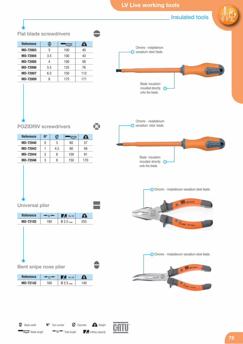
LV Live working tools
75
Insulated tools
75
Flat blade screwdrivers
Reference
MO-72003
MO-72004
MO-72005
MO-72006
MO-72007
MO-72009
3
3.5
4
5.5
6.5
8
100
100
100
125
150
175
40
43
58
76
112
171
mmmm
Reference
POZIDRIV screwdrivers
Reference
MO-72040
MO-72042
MO-72044
MO-72046
3
4.5
6
8
0
1
2
3
60
80
100
150
37
58
91
170
Chrome - molybdenumvanadium steel blade.
Blade insulationmoulded directlyonto the blade.
N°
Universal plier
MO-72102 Ø 2.5 max180 255
Cu / Al
Chrome - molybdenum vanadium steel blade.
Reference
Bent snipe nose plier
MO-72142 Ø 2.5 max160 140
Cu / Al
Chrome - molybdenumvanadium steel blade.
Blade insulationmoulded directlyonto the blade.
Chrome - molybdenum vanadium steel blade.
g
mm
mm mm
g
g
mm mmg
mm
mmDiametermm Blade width g Weight
mm Total lengthmm Blade length mm Cutting capacity
Tool numberN°

76
Reference
Flat nose plier
MO-72132 160 140
Reference
Round nose plier
MO-72122 160 140
Side cutter
Reference
MO-72162 Ø 4 max160 212
Cu / Al
Cable cutter
Reference
MO-72200 Ø 5 max160 238
Cu / Al
Wire stripping plier
Reference
MO-72172 Ø 5 max160 166
Cu / Al
Special steel,chrome matfinished.
Special steel,chrome matfinished.
Special steel,chrome matfinished.
Special steel,chrome matfinished.
Special steel,chrome matfinished.
Reference
Water pump plier
MO-72155 250 347
Special steel.
g Weightmm Total length
mm Cutting capacitymm Stripping capacity
mm g
mm g
mm gmm
mmmm g
mm g
mm gmm
Insulated tools
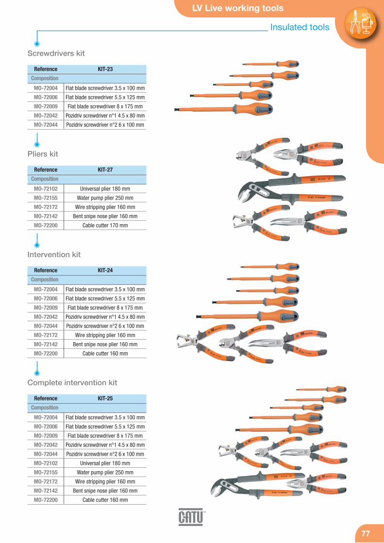
LV Live working tools
7777
Screwdrivers kit
Composition
MO-72004
MO-72006
MO-72009
MO-72042
MO-72044
Flat blade screwdriver 3.5 x 100 mm
Flat blade screwdriver 5.5 x 125 mm
Flat blade screwdriver 8 x 175 mm
Pozidriv screwdriver n°1 4.5 x 80 mm
Pozidriv screwdriver n°2 6 x 100 mm
Reference KIT-23
Composition
MO-72102
MO-72155
MO-72172
MO-72142
MO-72200
Universal plier 180 mm
Water pump plier 250 mm
Wire stripping plier 160 mm
Bent snipe nose plier 160 mm
Cable cutter 170 mm
Reference KIT-27
Pliers kit
Composition
MO-72004
MO-72006
MO-72009
MO-72042
MO-72044
MO-72172
MO-72142
MO-72200
Flat blade screwdriver 3.5 x 100 mm
Flat blade screwdriver 5.5 x 125 mm
Flat blade screwdriver 8 x 175 mm
Pozidriv screwdriver n°1 4.5 x 80 mm
Pozidriv screwdriver n°2 6 x 100 mm
Wire stripping plier 160 mm
Bent snipe nose plier 160 mm
Cable cutter 160 mm
Reference KIT-24
Intervention kit
Composition
MO-72004
MO-72006
MO-72009
MO-72042
MO-72044
MO-72102
MO-72155
MO-72172
MO-72142
MO-72200
Flat blade screwdriver 3.5 x 100 mm
Flat blade screwdriver 5.5 x 125 mm
Flat blade screwdriver 8 x 175 mm
Pozidriv screwdriver n°1 4.5 x 80 mm
Pozidriv screwdriver n°2 6 x 100 mm
Universal plier 180 mm
Water pump plier 250 mm
Wire stripping plier 160 mm
Bent snipe nose plier 160 mm
Cable cutter 160 mm
Reference KIT-25
Complete intervention kit
Insulated tools
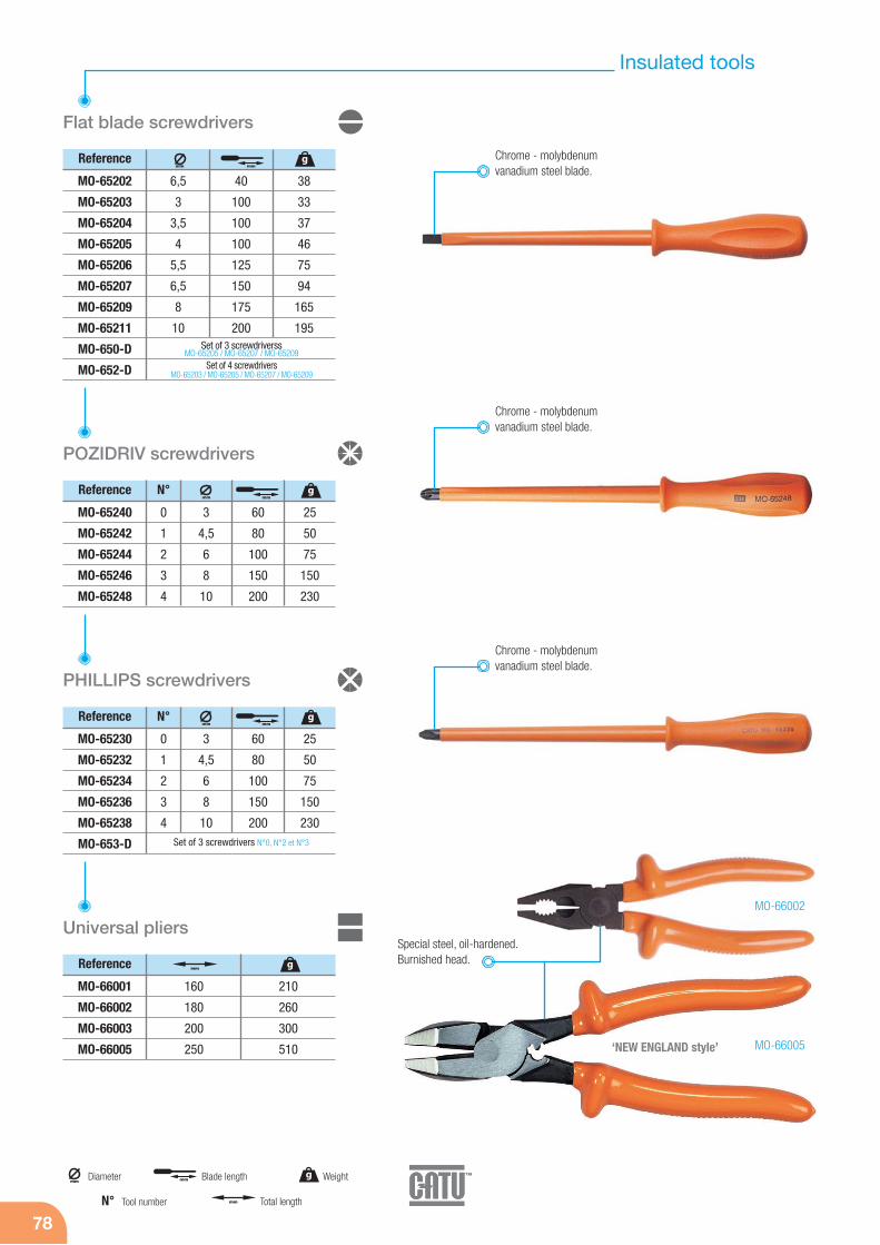
78
Flat blade screwdrivers
Reference
6,5
3
3,5
4
5,5
6,5
8
10
40
100
100
100
125
150
175
200
38
33
37
46
75
94
165
195
Chrome - molybdenumvanadium steel blade.
Chrome - molybdenumvanadium steel blade.
Chrome - molybdenumvanadium steel blade.
MO-65202
MO-65203
MO-65204
MO-65205
MO-65206
MO-65207
MO-65209
MO-65211
MO-650-D
MO-652-D
Set of 3 screwdriverssMO-65205 / MO-65207 / MO-65209
Set of 4 screwdrivers MO-65203 / MO-65205 / MO-65207 / MO-65209
PHILLIPS screwdrivers
Reference
MO-65230
MO-65232
MO-65234
MO-65236
MO-65238
MO-653-D
POZIDRIV screwdrivers
Reference
MO-65240
MO-65242
MO-65244
MO-65246
MO-65248
3
4,5
6
8
10
0
1
2
3
4
60
80
100
150
200
25
50
75
150
230
N°
3
4,5
6
8
10
0
1
2
3
4
60
80
100
150
200
25
50
75
150
230
N°
MO-66005
MO-66002
Set of 3 screwdrivers N°0, N°2 et N°3
Reference
Universal pliers
MO-66001
MO-66002
MO-66003
MO-66005
160
180
200
250
210
260
300
510
Special steel, oil-hardened.Burnished head.
mmDiameter g Weight
mm Total length
mm Blade length
Tool numberN°
mmg
mm
mmg
mm
mmg
mm
mm g
‘NEW ENGLAND style’
Insulated tools
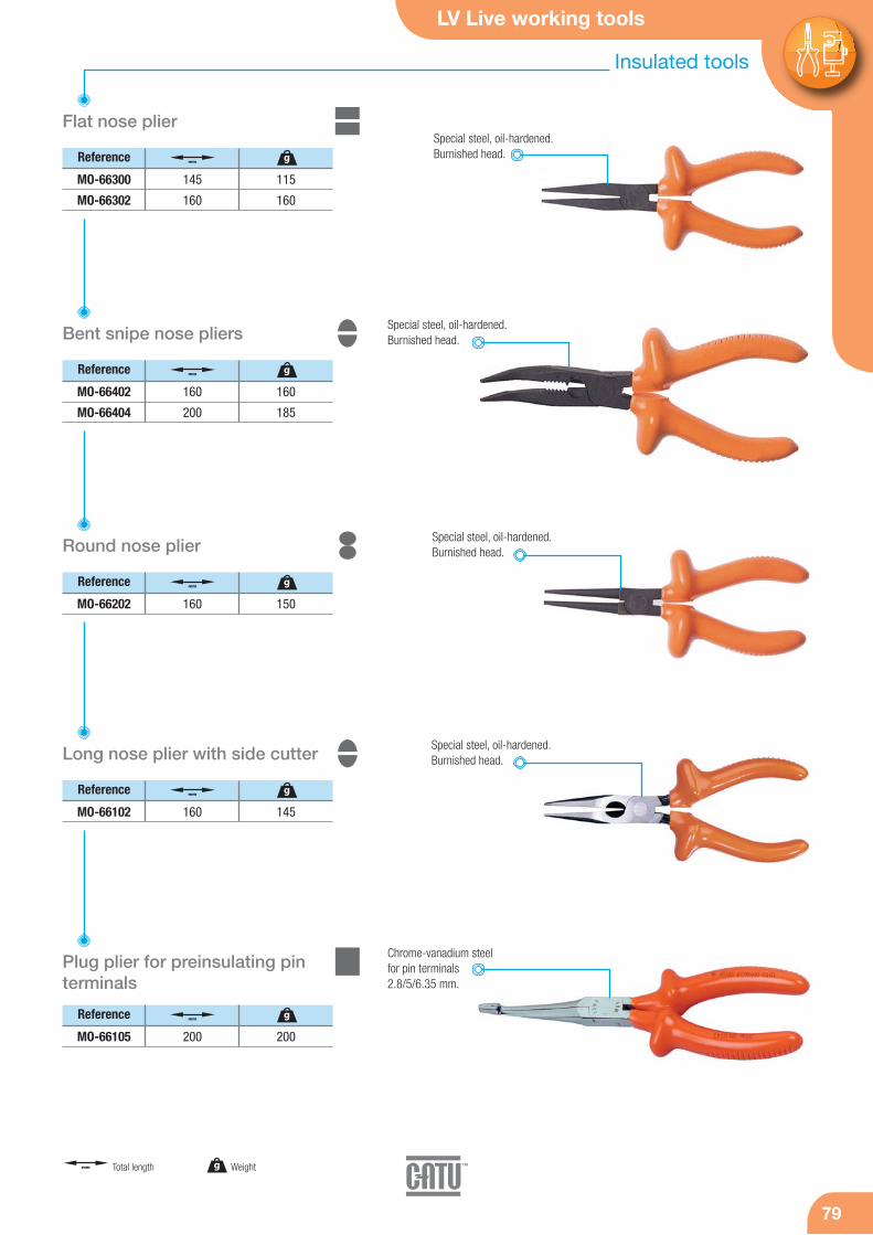
LV Live working tools
7979
Reference
Flat nose plier
MO-66300
MO-66302
145
160
115
160
Reference
Bent snipe nose pliers
MO-66402
MO-66404
160
200
160
185
Special steel, oil-hardened.Burnished head.
Special steel, oil-hardened.Burnished head.
Reference
Round nose plier
MO-66202 160 150
Special steel, oil-hardened.Burnished head.
Reference
Long nose plier with side cutter
MO-66102 160 145
Chrome-vanadium steelfor pin terminals2.8/5/6.35 mm.
Reference
Plug plier for preinsulating pinterminals
MO-66105 200 200
g Weightmm Total length
mm g
mm g
mm g
mm g
mm g
Special steel, oil-hardened.Burnished head.
Insulated tools
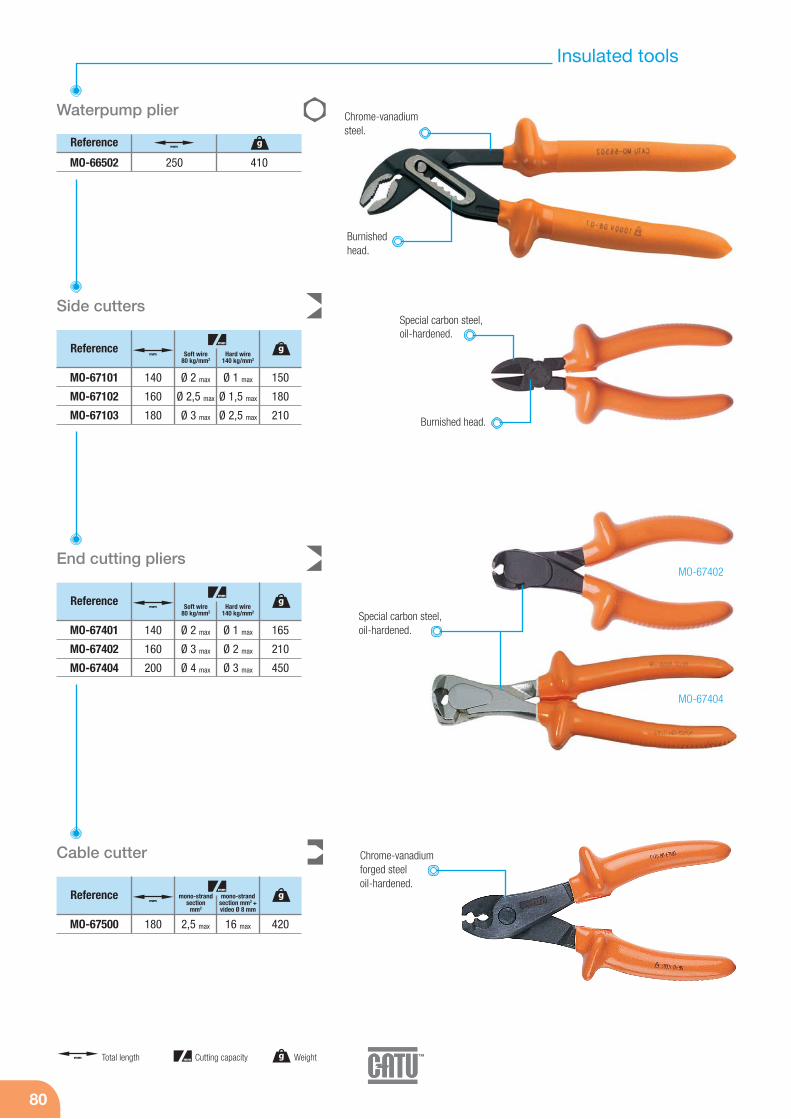
80
Reference
Waterpump plier
MO-66502 250 410
Side cutters
Reference
MO-67101
MO-67102
MO-67103
Ø 2 max
Ø 2,5 max
Ø 3 max
140
160
180
Ø 1 max
Ø 1,5 max
Ø 2,5 max
150
180
210
Soft wire80 kg/mm2
Hard wire140 kg/mm2
Special carbon steel,oil-hardened.
Burnished head.
End cutting pliers
Reference
MO-67401
MO-67402
MO-67404
Ø 2 max
Ø 3 max
Ø 4 max
140
160
200
Ø 1 max
Ø 2 max
Ø 3 max
165
210
450
Soft wire80 kg/mm2
Hard wire140 kg/mm2
Reference
MO-67500 2,5 max180 16 max 420
mono-strandsection
mm2
mono-strandsection mm2 +video Ø 8 mm
Chrome-vanadiumsteel.
Burnishedhead.
MO-67402
MO-67404
Special carbon steel,oil-hardened.
Cable cutter Chrome-vanadiumforged steel oil-hardened.
g Weightmm Total length mm Cutting capacity
mm g
mmg
mm
mmg
mm
mmg
mm
Insulated tools

LV Live working tools
8181
Reference Coppersection mm2
Aluminiumsection mm2
Cable cutters
Reference
MO-67501
MO-67502
Ø 15 max
Ø 20 max
170
230
285
520
Ratchet cable cutters
MO-67599
MO-67600
MO-67601
900
950
975
Chrome-vanadium forgedsteel oil-hardened.
MO-67501
MO-67502
Ø 32 max
Ø 38 max
Ø 55 max
180
240
300
250
300
450
Reference Coppersection mm2
Aluminiumsection mm2
Frontal ratchet cable cutter
MO-67611 900Ø 32 max 180 250
Treated forgedsteel blade.
Treated forgedsteel blade.
MO-67599
MO-67600
g Weightmm Total length mm Cutting capacity
gmm
mm
gmm
mm
mm gmm
Insulated tools

82
Hacksaw
Reference
MO-64502 300450 780mm
Protectedhard forgedsteel.
Two blade positions. Flushand 90° cutting supplied.
Delivered with pouch.
Tension bladeby screw.
Stripping plier for LV cables
Stripping pliers for LV cables
Reference
MO-67305
MO-67306
de 16 à 150
de 50 à 240
265
270
650
670
Stripping capacitymm2
Reference
MO-67304 de 16 à 150220 470
Stripping capacitymm2
Wire stripping plier
Reference
MO-67302 de 0.6 à 10160 170
Stripping capacitymm2
Stripping knives
Aluminium casting plier.
Aluminium castingplier.
Chrome vanadiumsteel. Burnishedhead.
Reference
180
180
62
50
110
110
MO-61001
MO-61002
Delivered with 2 blades.
Curved blade.
g Weightmm Total length
mm Blade length mm Stripping capacity
mm g
mmmm g
mmg
mm
mmg
mm
mmg
mm
Insulated tools
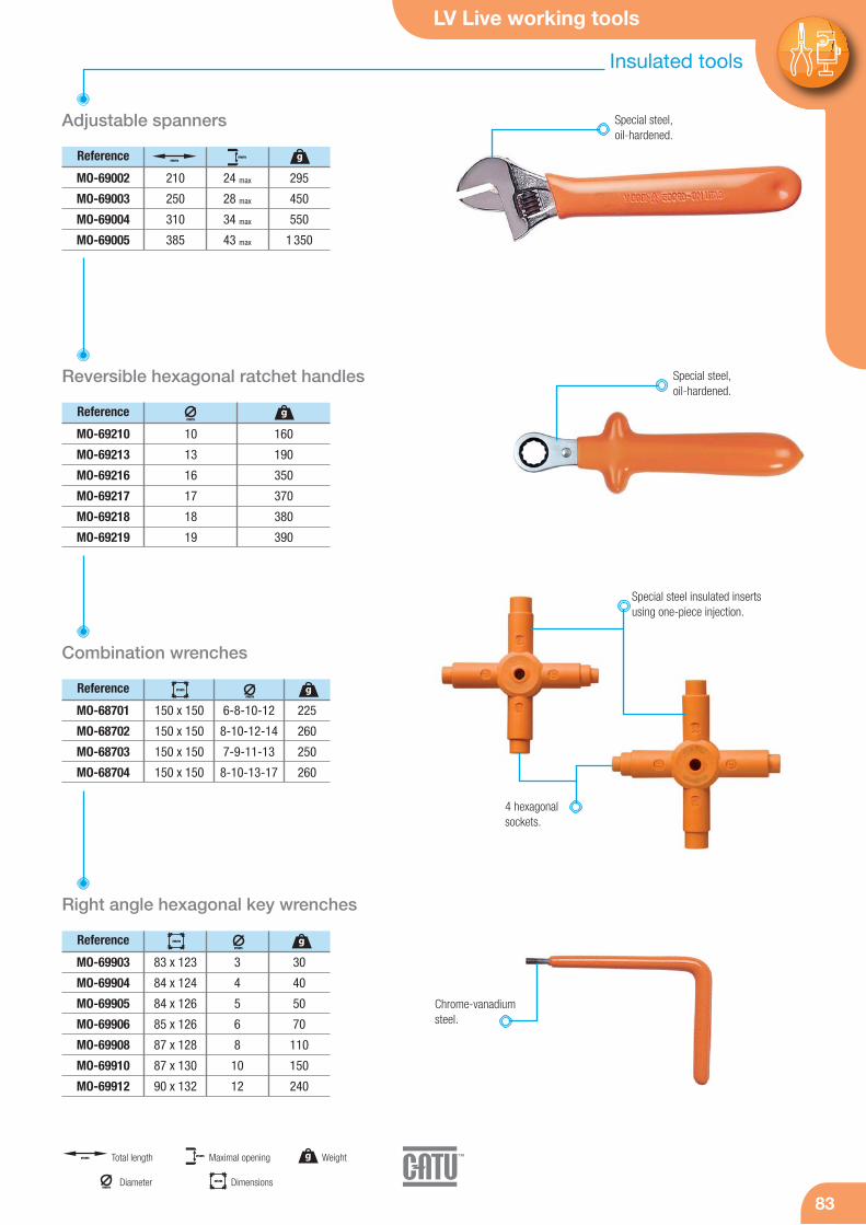
LV Live working tools
8383
Adjustable spanners
Reference
210
250
310
385
24 max
28 max
34 max
43 max
295
450
550
1 350
MO-69002
MO-69003
MO-69004
MO-69005
Special steel,oil-hardened.
Reference
Reversible hexagonal ratchet handles
MO-69210
MO-69213
MO-69216
MO-69217
MO-69218
MO-69219
10
13
16
17
18
19
160
190
350
370
380
390
Reference
Combination wrenches
MO-68701
MO-68702
MO-68703
MO-68704
150 x 150
150 x 150
150 x 150
150 x 150
225
260
250
260
6-8-10-12
8-10-12-14
7-9-11-13
8-10-13-17
Special steel,oil-hardened.
Special steel insulated inserts using one-piece injection.
4 hexagonalsockets.
Reference
Right angle hexagonal key wrenches
MO-69903
MO-69904
MO-69905
MO-69906
MO-69908
MO-69910
MO-69912
30
40
50
70
110
150
240
3
4
5
6
8
10
12
Chrome-vanadiumsteel.
83 x 123
84 x 124
84 x 126
85 x 126
87 x 128
87 x 130
90 x 132
mmDiameter mm Dimensions
g Weightmm Total length mm Maximal opening
mmmm g
gmm
gmm
mm
gmm
mm
Insulated tools

84
Open end spanners
Reference
8 max
9 max
10 max
11 max
12 max
13 max
14 max
15 max
16 max
17 max
18 max
19 max
40
40
45
50
60
80
100
110
120
140
160
170
MO-68008
MO-68009
MO-68010
MO-68011
MO-68012
MO-68013
MO-68014
MO-68015
MO-68016
MO-68017
MO-68018
MO-68019
MO-68008/19 8 open end spanners set: 8 / 10 / 11 / 12 / 13 / 14 / 17 / 19 mm
Reference
20 max
21 max
22 max
23 max
24 max
25 max
26 max
27 max
28 max
29 max
30 max
32 max
185
200
220
250
260
280
300
340
360
400
500
570
685
MO-68020
MO-68021
MO-68022
MO-68023
MO-68024
MO-68025
MO-68026
MO-68027
MO-68028
MO-68029
MO-68030
MO-68032
Cranked ring wrenches
Reference
7
8
9
10
11
12
13
14
15
16
17
18
19
35
40
45
50
65
80
100
120
150
180
190
195
200
MO-68107
MO-68108
MO-68109
MO-68110
MO-68111
MO-68112
MO-68113
MO-68114
MO-68115
MO-68116
MO-68117
MO-68118
MO-68119
Reference
20
21
22
23
24
25
26
27
28
29
30
32
–
240
260
260
270
280
300
360
400
440
480
500
540
–
MO-68120
MO-68121
MO-68122
MO-68123
MO-68124
MO-68125
MO-68126
MO-68127
MO-68128
MO-68129
MO-68130
MO-68132
–
Chrome-vanadium steel.
Chrome-vanadium steel.
Chrome steel.Hexagonal spanners with T handle
Reference
10
13
14
145
185
220
MO-68610
MO-68613
MO-68614
g Weightmm Maximal opening
mm g
mm g
mm g
mm g
mm g
Insulated tools
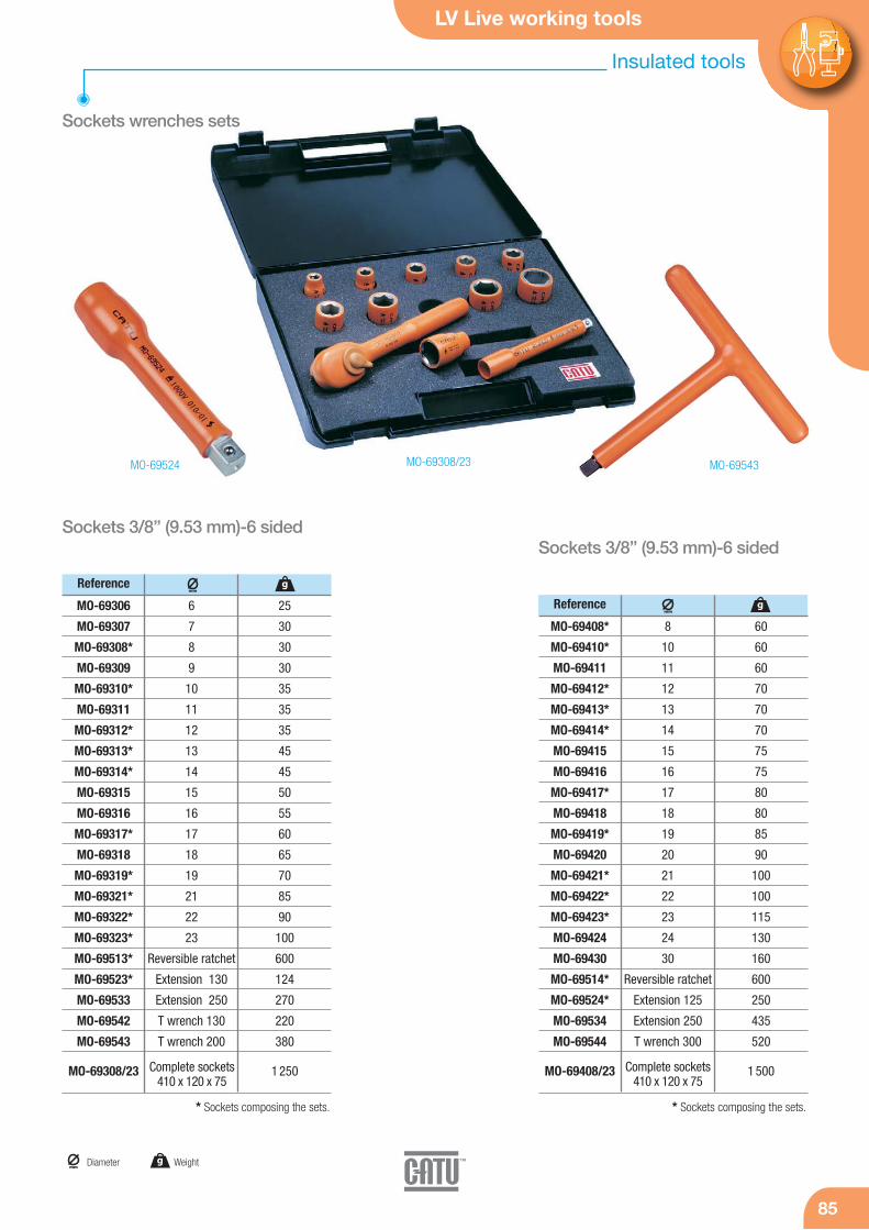
LV Live working tools
8585
Reference
Sockets 3/8” (9.53 mm)-6 sidedSockets 3/8” (9.53 mm)-6 sided
MO-69306
MO-69307
MO-69308*
MO-69309
MO-69310*
MO-69311
MO-69312*
MO-69313*
MO-69314*
MO-69315
MO-69316
MO-69317*
MO-69318
MO-69319*
MO-69321*
MO-69322*
MO-69323*
MO-69513*
MO-69523*
MO-69533
MO-69542
MO-69543
MO-69308/23
6
7
8
9
10
11
12
13
14
15
16
17
18
19
21
22
23
Reversible ratchet
Extension 130
Extension 250
T wrench 130
T wrench 200
25
30
30
30
35
35
35
45
45
50
55
60
65
70
85
90
100
600
124
270
220
380
1 250
Reference
MO-69408*
MO-69410*
MO-69411
MO-69412*
MO-69413*
MO-69414*
MO-69415
MO-69416
MO-69417*
MO-69418
MO-69419*
MO-69420
MO-69421*
MO-69422*
MO-69423*
MO-69424
MO-69430
MO-69514*
MO-69524*
MO-69534
MO-69544
MO-69408/23
8
10
11
12
13
14
15
16
17
18
19
20
21
22
23
24
30
Reversible ratchet
Extension 125
Extension 250
T wrench 300
60
60
60
70
70
70
75
75
80
80
85
90
100
100
115
130
160
600
250
435
520
1 500Complete sockets410 x 120 x 75
Complete sockets410 x 120 x 75
MO-69524 MO-69543MO-69308/23
* Sockets composing the sets. * Sockets composing the sets.
mmDiameter g Weight
gmm
gmm
Sockets wrenches sets
Insulated tools
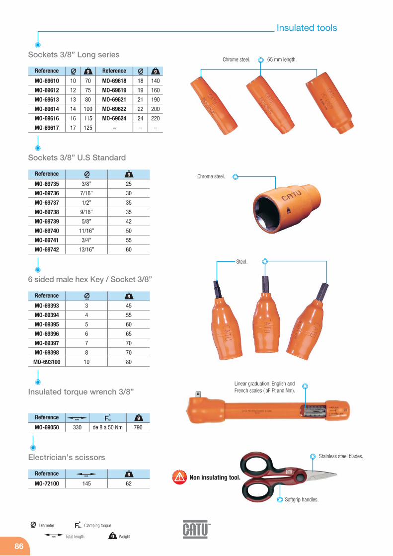
86
Reference
MO-69610
MO-69612
MO-69613
MO-69614
MO-69616
MO-69617
10
12
13
14
16
17
70
75
80
100
115
125
Sockets 3/8” Long series
Reference
MO-69735
MO-69736
MO-69737
MO-69738
MO-69739
MO-69740
MO-69741
MO-69742
3/8”
7/16”
1/2”
9/16”
5/8”
11/16”
3/4”
13/16”
25
30
35
35
42
50
55
60
Sockets 3/8” U.S Standard
Reference
MO-69393
MO-69394
MO-69395
MO-69396
MO-69397
MO-69398
MO-693100
3
4
5
6
7
8
10
45
55
60
65
70
70
80
6 sided male hex Key / Socket 3/8”
Reference
MO-69050 de 8 à 50 Nm 790
Insulated torque wrench 3/8”
65 mm length.Chrome steel.
Chrome steel.
Steel.
Linear graduation, English andFrench scales (ibF Ft and Nm).
330
mmDiameter
g Weightmm Total length
FNm Clamping torque
gmm
gmm
gmm
gmm FNm
Reference
MO-69618
MO-69619
MO-69621
MO-69622
MO-69624
–
18
19
21
22
24
–
140
160
190
200
220
–
gmm
Reference
Electrician’s scissors
MO-72100 145 62
gmm Non insulating tool.
Stainless steel blades.
Softgrip handles.
Insulated tools

LV Live working tools
8787
Screwdrivers kit
Composition
MO-65242
MO-65244
MO-65204
MO-65206
MO-65209
Pozidriv screwdriver N°1
Pozidriv screwdriver N°2
Flat blade screwdriver 3.5 x 100 mm
Flat blade screwdrivere 5.5 x 125 mm
Flat blade screwdriver 8 x 175 mm
Reference KIT-03
Composition
MO-66002
MO-66502
MO-67302
MO-66402
MO-67500
Universal pliers overall length 180 mm
Water pump pliers overall length 250 mm
End stripping pliers 160 mm
Bent snipe nose pliers overall 160 mm
Cable cutter 170 mm
Reference KIT-07
Composition
MO-65242
MO-65244
MO-65204
MO-65206
MO-65209
MO-67302
MO-66402
MO-67500
Pozidriv screwdriver N°1
Pozidriv screwdriver N°2
Flat blade screwdriver 3.5 x 100 mm
Flat blade screwdriver 5.5 x 125 mm
Flat blade screwdriver 8 x 175 mm
End stripping pliers overall 160 mm
Bent snipe nose pliers overall 160 mm
Cable cutter 170 mm
Reference KIT-04
Intervention kit
Composition
MO-65242
MO-65244
MO-65204
MO-65206
MO-65209
MO-66002
MO-66502
MO-67302
MO-66402
MO-67500
Pozidriv screwdriver N°1
Pozidriv screwdriver N°2
Flat blade screwdriver 3.5 x 100 mm
Flat blade screwdriver 5.5 x 125 mm
Flat blade screwdriver 8 x 175 mm
Universal pliers overall 180 mm
Water pump pliers overall 250 mm
End stripping pliers overall 160 mm
Bent snipe nose pliers overall 160 mm
Cable cutter 170 mm
Reference KIT-05
Complete intervention kit
Pliers kit
Insulated tools
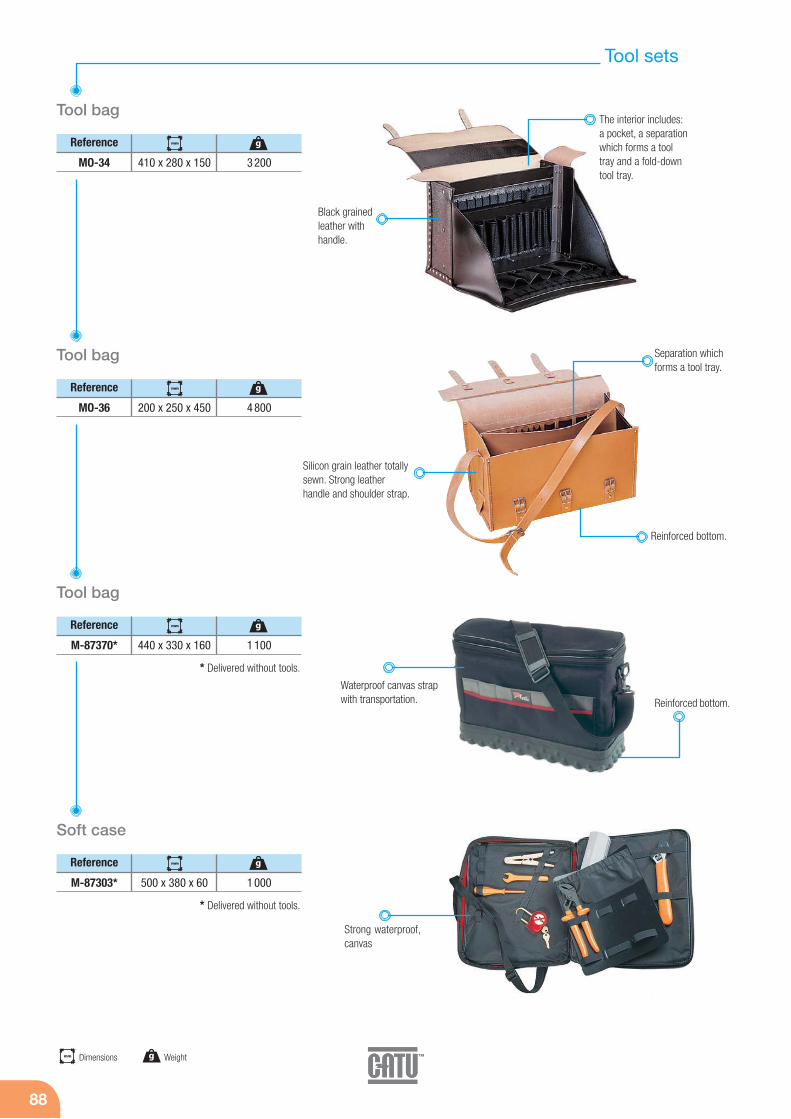
88
Tool sets
Reference
Tool bag
MO-34 410 x 280 x 150 3 200
Reference
Tool bag
MO-36 200 x 250 x 450 4 800
Reference
Tool bag
M-87370* 440 x 330 x 160 1 100
Reference
Soft case
M-87303* 500 x 380 x 60 1 000
Black grainedleather withhandle.
Silicon grain leather totallysewn. Strong leatherhandle and shoulder strap.
Waterproof canvas strapwith transportation.
The interior includes:a pocket, a separationwhich forms a tooltray and a fold-downtool tray.
Strong waterproof,canvas
Reinforced bottom.
Separation whichforms a tool tray.
Reinforced bottom.
* Delivered without tools.
* Delivered without tools.
mm Dimensions g Weight
g
g
g
g
mm
mm
mm
mm

LV Live working tools
898
Tool sets
89
Low voltage complete set.Complete equipment for live line (LV) interventions.
Bag tool bag to order separately
1 right angle hexagonal key wrench 3 mm
1 right angle hexagonal key wrench 4 mm
1 right angle hexagonal key wrench 6 mm
1 insulating folding rule
1 adjustable spanner 250 mm
1 universal pliers 180 mm
1 round nose pliers 160 mm
1 water pump pliers 250 mm
1 side cutter 160 mm
1 flat blade screwdriver 4 x 100
1 flat blade screwdriver 6.5 x 150
1 flat blade screwdriver 8 x 175
1 Phillips screwdriver n° 1
1 Phillips screwdriver n° 2
1 Phillips screwdriver n° 3
MO-69903
MO-69904
MO-69906
MO-751
MO-69003
MO-66002
MO-66202
MO-66502
MO-67102
MO-69308/23
MO-65205
MO-65207
MO-65209
MO-65232
MO-65234
MO-65236
Insulating tools
following… MO-510-03-EX *
1 sockets 3/8" wrench set with 10 sockets: 8, 10, 12, 13, 14, 17, 19, 21, 22, 23
Personal equipment
MO-186
CG-98-C
CG-05-B
CG-36
MP-42/16
MS-917 EX
MP-26-A
MP-35/12
MP-39
MP-32/15
MP-19
MO-61001
MO-67502
MO-68008/19
1 face shield
1 working gloves size C
1 rubber gloves size B
1 carrying bag for rubber gloves
1 insulating mat 3 mm
1 voltage detector
10 insulating caps
1 insulating blanket
10 wood clamps for insulating blanket
6 line protectors 1.50 m
5 insulating adhesive tapes
1 stripping knife
1 cable cutter 230 mm
Reference MO-510-03-EX*
1 open end spanners set with8 / 10 / 11 / 12 / 13 / 14 / 17 / 19 mm
Voltage detector
Insulating tools
Insulating
Reference Characteristics
MO-34
MP-01
Leather tool bag , see page 88
Bags for insulating mats, see page 25
Reference Characteristics
M-87384
M-87386
Bag for face shield and helmet, see page 18
Multi-pocket electrician bag, see page 25
* Delivered without tool bag. * Delivered without tool bag.

90
Tool sets
Intervention kit for electricians
Composition
M-87370
CG-05-C
MO-11001
AL-230-111
MO-65204
MO-65206
MO-65209
MO-65242
MO-65244
MO-66002
MO-66402
MO-67302
MO-67500
MO-66502
1 tool bag
1 pair of insulating gloves size C
1 safety glasses
1 safety padlock
Flat blade screwdriver - 3.5 x 100 mm
Flat blade screwdriver - 5.5 x 125 mm
Flat blade screwdriver - 8 x 175 mm
Pozidriv screwdriver - N°1 4.5 x 80 mm
Pozidriv screwdriver - N°2 6 x 100 mm
Universal plier - length 180 mm
Bent snipe nose plier - length 160 mm
End stripping plier - length 160 mm
Cable cutter - length 170 mm
Water pump plier - length 250 mm
Reference MO-38510
Our guides and catalogues are availableon request or downloadable from ourwebsite:
www.catuelec.com
To help you in LV Live working,your guide is available.
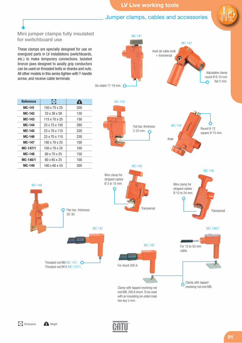
LV Live working tools
9191
These clamps are specially designed for use onenergized parts in LV installations (switchboards,etc.) to make temporary connections. Isolatedbronze jaws designed to axially grip conductorscan be used on threaded bolts or shanks and nuts.All other models in this series tighten with T-handlescrew, and receive cable terminals
Reference
Mini jumper clamps fully insulated for switchboard use
MC-141
MC-142
MC-143
MC-144
MC-145
MC-146
MC-147
MC-147/1
MC-148
MC-148/1
MC-149
150 x 75 x 25
33 x 38 x 58
115 x 70 x 25
23 x 75 x 150
23 x 70 x 110
23 x 70 x 110
100 x 70 x 25
100 x 70 x 25
80 x 70 x 25
80 x 65 x 25
160 x 60 x 55
200
130
150
280
220
230
100
100
150
100
300
Six-sided 17-19 mm.
Adjustable clamp round Ø 6-10 mm
flat 5 mm.
Threated rod M8 MC-147.Threated rod M10 MC-147/1.
Flat bar, thickness2-25 mm.
Round 8-12 square 9-10 mm.
Wire clamp forstripped cables Ø 3 to 10 mm. Wire clamp for
stripped cablesØ 10 to 24 mm.
MC-141
MC-142
MC-143
MC-144
MC-145MC-146
MC-149
Axial (at cable end)+ transversal
TransversalTransversal
Axial
Clamp with tapped revolving rodend M8, 200 A shunt. To be usedwith an insulating six-sided malehex key 5 mm.
MC-147
MC-148
MC-148/1
Clamp with tapped revolving rod end M8.
For 10 to 50 mmcable.
Flat bar, thickness20-30.
For shunt 200 A.
Jumper clamps, cables and accessories
mm Dimensions g Weight
gmm

92
Jumper clamps, cables and accessories
Jumper cable with insulated jumper clamps
Reference
MC-121
MC-122
MC-123
MC-124
60 x 25
125 x 35
125 x 35
125 x 35
50
100
100
100
Jumper cable with insulatedjumper clamps
Reference
MC-120/15
MC-120/50
MC-120/100
1 500
5 000
10 000
850
1 950
4 000
Jumper cables
Reference
MC-153/05
MC-153/10
MC-153/30
MC-153/60
MC-155/05
MC-155/10
MC-155/20
MC-155/30
MC-155/60
MC-155/80
500
1 000
3 000
6 000
500
1 000
2 000
3 000
6 000
8 000
270
570
1 720
3 460
380
760
1 520
2 280
4 560
6 080
35
35
35
35
50
50
50
50
50
50
LV live working tools.
Sectionsmm2
Delivered with socketscrewing ISO M8
Insolated cover.
Junction.
Fuse holder for Shunt.piece female-female.
piece male-female.
MC-121
MC-122
MC-123
Fuse holder for 30 A for Clamps + banana plug.
piece male-female.MC-124
Connector for cable 8 mm.
Rated insulation:1 500 V.
Icc = 5 kA/1 s.
2 clamps MC-120.150 x 100 x 60 mmand 190 g each.Tightening capacity.12 mm (- flat).Spring tightening.
Cable H 07 RN-F of 25 mm2
Continuous rating: 75 A.
Isolated copper cableH 07 RN-F.Nominal intensity200 A.
g Weightmm Total length
mm g
mm g
mm g

LV Live working tools
9393
Cylindrical body diameter10 mm to fits on panelnetwork threadof switchboard etc... Total length 50 mm.
Reference
MC-126
MC-126/1
de 1.5 à 16
de 10 à 70
60 A
100 A
Reference
MC-150 173 x Ø 32 185
Reference
Threaded adapter
MC-181
MC-182
MC-183
50
27
48
M10
M8
M12
50 x 13
50 x 10
50 x 17
Reference
Tap off box
MC-156
MC-156/1
MC-237-D
Box 40 x 80 x 158 mm
Spare part
Triangular spanner witch T hande
Reference
Jumper connecting box with fuse
MC-116 de 30 à 200 A
MC-183
MC-182
MC-181
Set of 4 adapters by reference.
The tap off box allows on each side to connect 3 by pass jumpers.
The shunt for collective channeling is a box usedto make sure, before proceeding to the replace-ment of a molten fuse situated on a channeling,that the defect which brought about the molten iseliminated. This box is used with a fuse when the(nominal) assigned intensity of the channeling is< 100 A and with 2 fuses when this intensity is in-cluded between 100 A and 200 A. It can also beused to open a circuit in load, for example tochange a damaged accessory such as a pin.
Jumper clamps, cables and accessories
Shunt Telescopic probe
Sections mm2 Intensity
Intensity
Characteristics
Connector with insulated probe.
Cover etractable accessory.
The six removable fittingscan be separated by thetriangular spanner.
Other connecting box: consult us.
Shunt forcollectivepipes.
mmDiametermm Dimensions g Weightmm Total length
mm g
gmm
mm
MC-150
MC-126
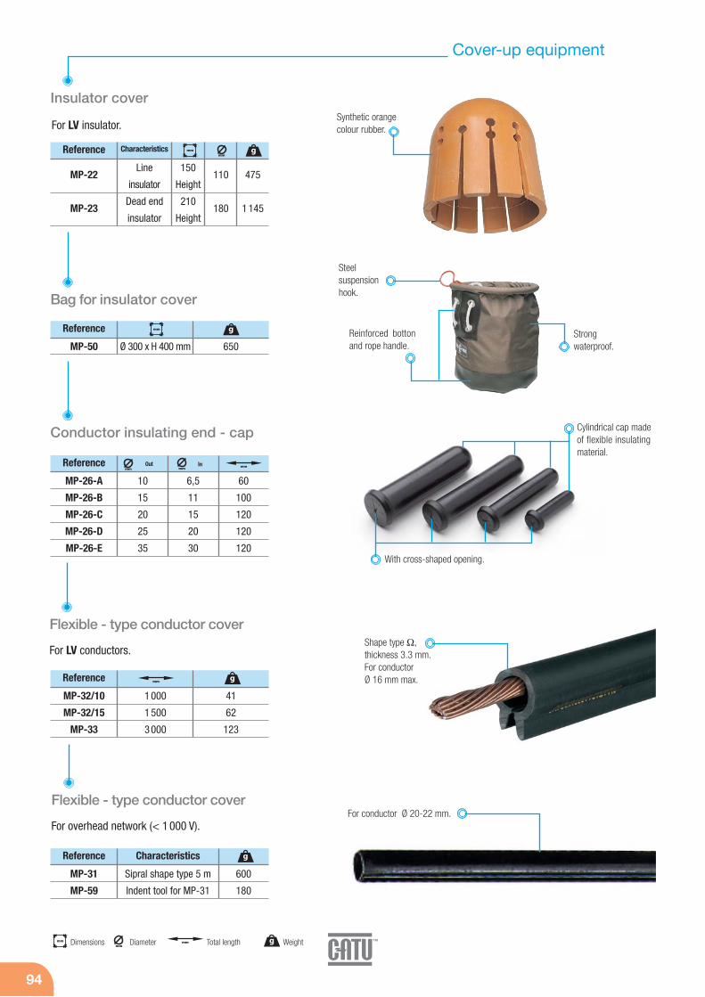
94
Cover-up equipment
For LV insulator.
Reference
Insulator cover
MP-22
MP-23
475
1 145
110
180
150
Height
210
Height
Synthetic orangecolour rubber.
Line
insulator
Dead end
insulator
Characteristics
Bag for insulator cover
Reinforced bottonand rope handle.
Reference
MP-50 Ø 300 x H 400 mm 650
Flexible - type conductor cover
Reference
MP-32/10
MP-32/15
MP-33
1 000
1 500
3 000
41
62
123
Conductor insulating end - cap
Strong waterproof.
Steel suspension hook.
For LV conductors.
Flexible - type conductor cover
Reference
MP-31
MP-59
Sipral shape type 5 m
Indent tool for MP-31
600
180
For overhead network (< 1 000 V).
Shape type Ω, thickness 3.3 mm.For conductor Ø 16 mm max.
Characteristics
For conductor Ø 20-22 mm.
mmDiametermm Dimensions g Weightmm Total length
gmm
mm
g
g
g
mm
mm
Cylindrical cap madeof flexible insulatingmaterial.
With cross-shaped opening.
Reference
MP-26-A
MP-26-B
MP-26-C
MP-26-D
MP-26-E
60
100
120
120
120
10
15
20
25
35
6,5
11
15
20
30
InOutmmmm
mm
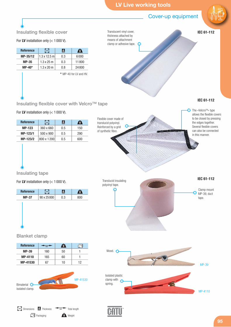
LV Live working tools
9595
Insulating flexible cover
Reference
MP-35/12
MP-35
MP-40*
1.3 x 12.5 m
1.3 x 25 m
1.3 x 20 m
0.3
0.3
0.8
6 000
11 800
24 800
For LV installation only (< 1 000 V).
Insulating flexible cover with Velcro™ tape
Reference
MP-123
MP-123/1
MP-123/2
360 x 660
500 x 900
800 x 1 200
0.5
0.5
0.5
150
290
600
For LV installation only (< 1 000 V).
Insulating tape
Reference
MP-37 90 x 25000 0.3 800
For LV installation only (< 1 000 V).
Translucent vinyl cover,thickness attached bymeans of attachmentclamp or adhesive tape.
* MP-40 for LV and HV.
Flexible cover made oftranslucid polyvinyl.Reinforced by a grid of synthetic fibre.
The «VelcroTM» typeallows the flexible coversto be closed by pressingthe edges together.Several flexible coverscan also be connectedin this manner.
Translucid insulatingpolyvinyl tape.
Clamp mountMP-39, ducttape.
MP-4110
MP-41530
MP-39
Wood.
mm Dimensions
g Weight
mm Total lengthémm Thickness
gmm émm
gmm émm
gmm émm
Bimaterial isolated clamp.
Blanket clamp
Reference
MP-39
MP-4110
MP-41530
160
165
67
50
60
10
1
1
12
gmm
Packaging
Isolated plasticclamp withspring.
Cover-up equipment
IEC 61-112
IEC 61-112
IEC 61-112

96
Insulating sticks
For working from a distance.
Wire-cutter stick
Reference
MG-116-S
MG-117-S
2 000
2 600
26
26
2 100
2 300
Out
Trammel mechanism with a two-part copper and alu-minium hook, with three positions:- open, outward-facing hook,- closed, outward-facing hook ("universal joint"
position),- closed, inward-facing hook ("transport" position),Automatic locking in "universal joint" position.
Universal hand stick
Reference
MG-125-K 2 600 32 1 300
Out
Hook stick (hook pole)
Reference
MG-130
MG-131
M-52-91/92
2 600
1 800
35
35
3 800
3 300
Extérieur
Set of two blades (fixed and moving)
Laminatedcontrol ring
movable in fivedirections at
350 mm intervals.
Cylindrical head underinsulating cap.
Insulating sus-pension hookon the top.
Insulatingsuspensionhook on the top.
Two "K" (universal)end-fittings at eachend, in light alloywith 12 teeth and an unloseablelocking screw.
Two reversesuspensionhooks.
Cutting capacity:- copper: 48 mm- aluminium: 54 mm- aluminium-steel: 37 mm- 120 kg/mm steel: 5 mm.
Metal controlhandle withinsulating coating.
Nondegradablemovement with laminated ring.
Sharpenable, inter-changeable blades.
MG-116-SMG-117-S
MG-130MG-131
MG-125-K
White epoxy resin/fibreglass cylindrical tubularpole body.
mmDiameter g Weightmm Total length
mm gmm
mm gmm
mm gmm

LV Live working tools
97
Cable identifier
97
Cable Identifier
Accessories
The MX-400 includes a modulator A and areceiver B.The MX-400 is a cable identifier that is particularlywell suited for quickly identifying underground cablesand insulating overhead lines. It is also designed foridentifying phases. This identifier is used on any typeof power distribution network with rated voltages of230 to 400 Volts.
Operating voltage: 230/400 V +/– 10%.Frequency: 50 Hz +/– 10%.Operating temperature: – 10° to + 55°C.Storage temperature: – 20° to + 70.Class II modulator.
Reference
MX-400 510 x 465 x 216 10 600
Reference
MX-400/1
MX-400/6
MX-400/7
MC-1421
Modulator + receiver
Receiver
Amperemetric clamp
Connection clamp
Comes complete with an ABS case, 2 cables,and 1 amperemetric clamp.
The modulator is an electronicpower system that draws currentpulses in 10-millisecond intervals ata frequency of 1 Hertz.Current limited by fuse, HPC 100 kA aM 10 A.
The receiver is equipped withtwo sensors that detect the pas-sage of pulses drawn by themodulator. Once these pulsesare received, the device emits alight signal, confirmed with abeep after three seconds.Receiver powered by 9 V lithiumtype 6LR61 battery.Sensor sensitivity adjustable to15 levels.Detection can easily be adjus-ted, which accordingly affectsidentification accuracy.
H07RNF power cables. (6 mm2 and 3 m length).The connection is made between phases for identifying the cable or between phase and neutralfor identifying a phase. After connection, the deviceis immediately live, as indicated by two 230 and400 Volts lights.
The phase is identified with anamperemetric clamp connectedto the receiver and positionedaround the phase to be identified.When the clamp detects pulsesdrawn by the modulator, the recei-ver emits a light signal, confirmedby a beep after three seconds.
Characteristics
mm Dimensions g Weight
gmm
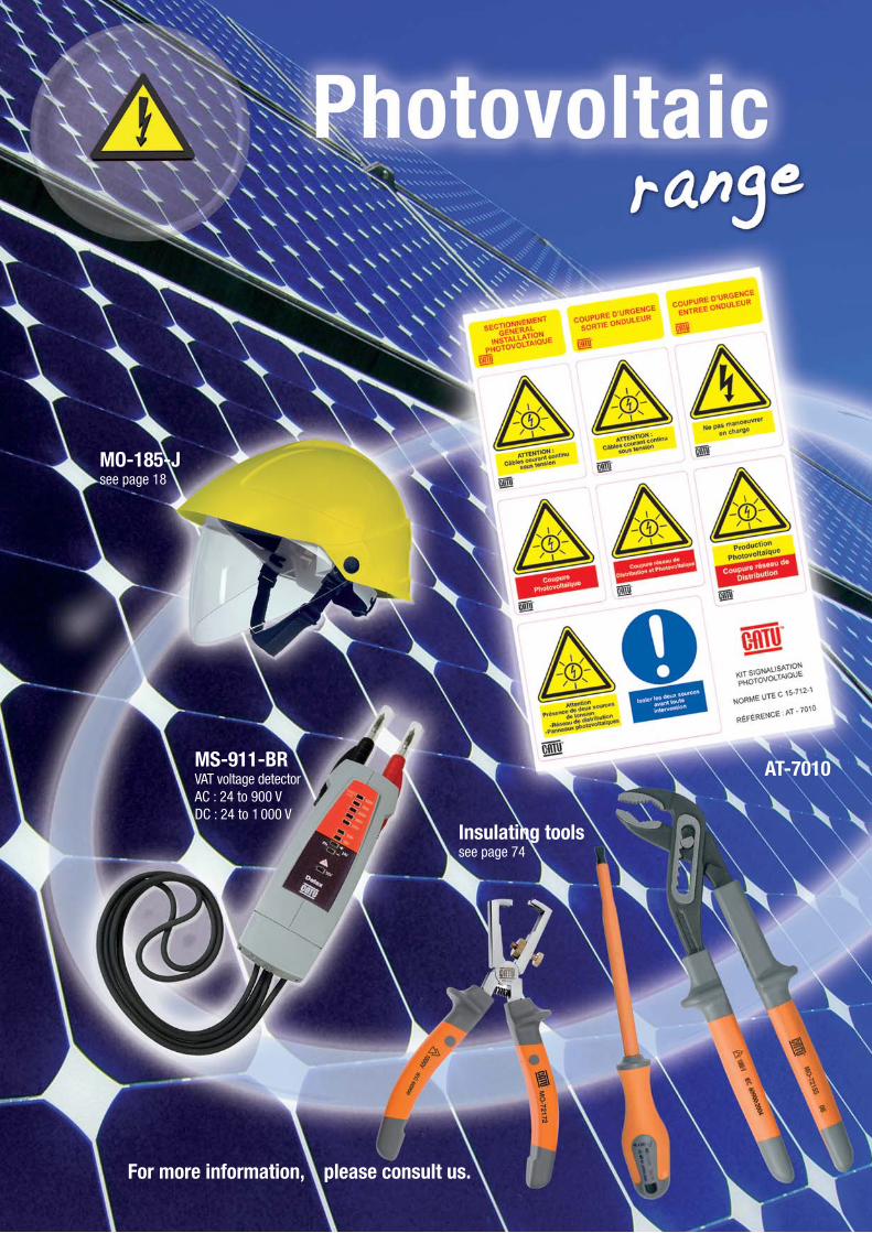
98
MS-911-BRVAT voltage detectorAC : 24 to 900 VDC : 24 to 1 000 V
MO-185-Jsee page 18
Insulating toolssee page 74
AT-7010
For more information, please consult us.
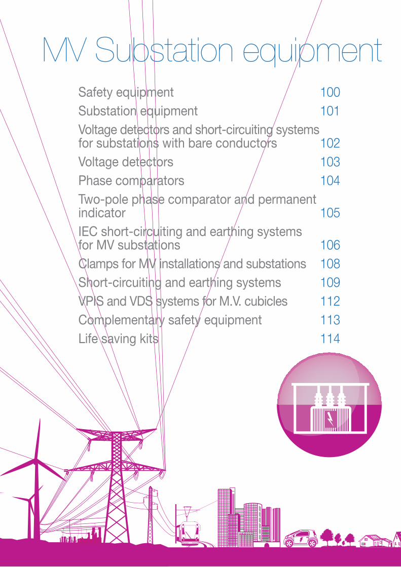
Safety equipment 100Substation equipment 101Voltage detectors and short-circuiting systemsfor substations with bare conductors 102Voltage detectors 103Phase comparators 104Two-pole phase comparator and permanent indicator 105IEC short-circuiting and earthing systems for MV substations 106Clamps for MV installations and substations 108Short-circuiting and earthing systems 109VPIS and VDS systems for M.V. cubicles 112Complementary safety equipment 113Life saving kits 114
MV Substation equipment

100
Safety EquipmentKeep your substations in compliance
Special regulatory signaling
The standard recommends the following signalingin substations:- A substation poster,- Two posters about what to do in the event of an
indoor or outdoor electrical emergency,- A poster displays the service rules.
All of these posters comes in kits that werespecially designed by CATU to get yoursubstations in compliance.
Safety Equipment
The standard recommends the following serviceequipment:- An insulating platform or an insulated mat,- A rescue pole,- A pair of insulating gloves adjusted to the
sub-station's rated voltage,- A voltage detector (see below for information)- A grounding and short
circuit device (see belowfor information)
- A glove box,- A fuse holder.CATU has assembled all ofthe service equipment into kitsto simplify your selection and tobring your facilities into complianceright away. This equipment must include a suitable voltage detector.
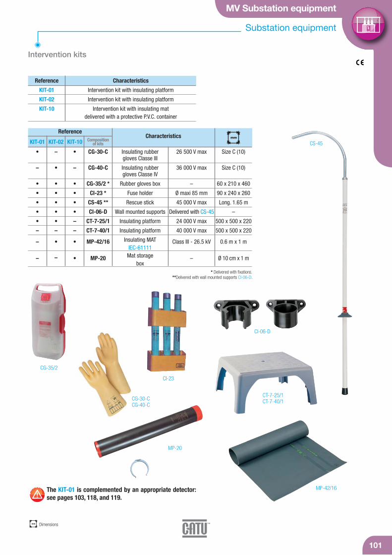
MV Substation equipment
Substation equipment
101
Reference Characteristics
Intervention kits
MP-42/16
MP-20
CG-35/2
CI-23
KIT-02KIT-01
•
–
•
•
•
•
•
–
–
–
–
•
•
•
•
•
•
–
•
–
KIT-10
•
–
•
•
•
•
–
–
•
•
ReferenceCharacteristics
CG-30-C
CG-40-C
CG-35/2 *
CI-23 *
CS-45 **
CI-06-D
CT-7-25/1
CT-7-40/1
MP-42/16
MP-20
Composition of kits
KIT-01
KIT-02
KIT-10
Intervention kit with insulating platform
Intervention kit with insulating platform
Intervention kit with insulating matdelivered with a protective P.V.C. container
Insulating rubber gloves Classe III
Insulating rubber gloves Classe IV
Rubber gloves box
Fuse holder
Rescue stick
Wall mounted supports
Insulating platform
Insulating platform
Insulating MATIEC-61111
Mat storage box
26 500 V max
36 000 V max
–
Ø maxi 85 mm
45 000 V max
Delivered with CS-45
24 000 V max
40 000 V max
Class III - 26.5 kV
–
mm
Size C (10)
Size C (10)
60 x 210 x 460
90 x 240 x 260
Long. 1.65 m
–
500 x 500 x 220
500 x 500 x 220
0.6 m x 1 m
Ø 10 cm x 1 m
CS-45
CG-30-CCG-40-C
CT-7-25/1CT-7-40/1
CI-06-D
mm Dimensions
* Delivered with fixations.**Delivered with wall mounted supports CI-06-D.
The KIT-01 is complemented by an appropriate detector:see pages 103, 118, and 119.
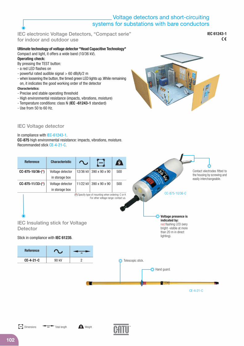
Voltage detectors and short-circuiting systems for substations with bare conductors
102
CE-4-21-C
IEC Insulating stick for VoltageDetector
Stick in compliance with IEC 61235.
CE-4-21-C 90 kV 2
Referencem
IEC electronic Voltage Detectors, “Compact serie”for indoor and outdoor use
Ultimate technology of voltage detector "Head Capacitive Technology"Compact and light, it offers a wide band (10/36 kV).Operating check:By pressing the TEST button:- a red LED flashes on- powerful rated audible signal > 60 dB(A)/2 m- when loosening the button, the timed green LED lights up. While remaining
on, it indicates the good working order of the detectorCharacteristics:- Precise and stable operating threshold- High environmental resistance (impacts, vibrations, moisture)- Temperature conditions: class N (IEC -61243-1 standard)- Use from 50 to 60 Hz.
Voltage presence isindicated by:red flashing LED (verybright -visible at morethan 20 m in direct lighting).
Contact electrodes fitted tothe housing by screwing andeasily interchangeable.
CC-875-10/36-C
Reference gCharacteristic
500CC-875-10/36-(*) 390 x 90 x 90Voltage detector
in storage box
mm
12/36 kV
IEC Voltage detector
In compliance with IEC-61243-1.CC-875 high environmental resistance: impacts, vibrations, moisture.Recommanded stick CE-4-21-C.
Telescopic stick.
Hand guard.
mm Dimensions g Weightmm Total length
CC-875-11/33-(*) 500390 x 90 x 90Voltage detector
in storage box
11/22 kV
IEC 61243-1
(*) Specify type of mounting when ordering: C or K For other voltage range: contact us.

MV Substation equipment
103
C-18-311
Voltage detectors
CL-4-10/30-2
Built-in device for checking operation of the led’s indicator via a piezo-electric generator.High-brightness led’s indicator.
Voltage detector with leds for indoor use without batteries
CL-4-10/30-M
For indoor use. This compact serie voltage detector is designed to becarried easily by operators. Voltage presence is indicated by ahigh-brightness LED’s indicator. Built-in device for checking of theLED’s indicator by a piezotest generator.
Voltage detector with leds for indoor use (Compact serie) without batteries
Sturdy thermo-plastic moulded case providing.
Pivoting contact electrodeenabling wire contact at any angle.
Fixed stick.
10-30 kV
10-30 kV
1 000
950
Reference g
* Delivered in vinyl sheath with wall brackets CI-06-D.** Delivered in canvas, waterproofed with ramp.
CL-4-10/30-M *
CL-4-10/30-2 **
–
0.85
1.35
1.26
m
Folded up m
5-36 kV
10-30 kV
400
400
Reference g
Other models fixed or telescopic, please contact us.Delivered in holster.
CL-2-5/36-2
CL-2-10/30-2
0.33
0.33
0.9
0.9
m
Folded up m
Equipped with a telescopic handle.
Contact electrode.
Ø 58.5 mm compatiblewith aperturehousing.
Telescopic insulating stick.
g Weightmm Total length
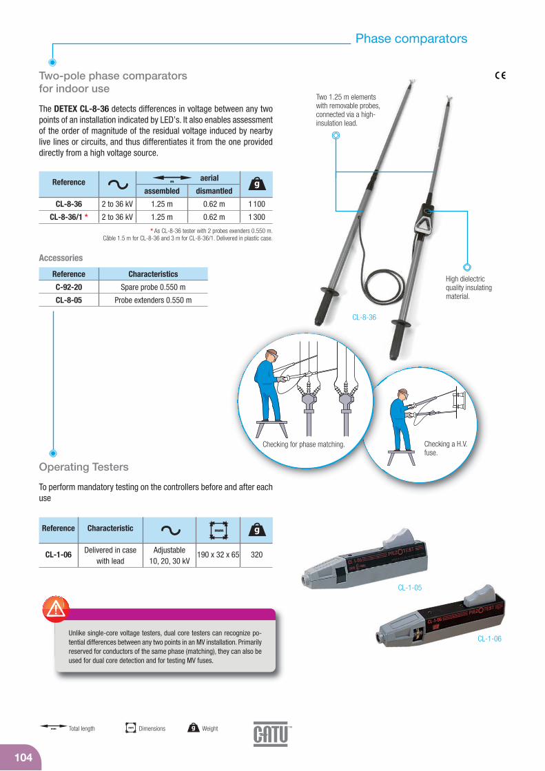
CL-8-36
Phase comparators
Two-pole phase comparators for indoor use
The DETEX CL-8-36 detects differences in voltage between any twopoints of an installation indicated by LED’s. It also enables assessmentof the order of magnitude of the residual voltage induced by nearbylive lines or circuits, and thus differentiates it from the one provideddirectly from a high voltage source.
104
Unlike single-core voltage testers, dual core testers can recognize po-tential differences between any two points in an MV installation. Primarilyreserved for conductors of the same phase (matching), they can also beused for dual core detection and for testing MV fuses.
CL-1-05
CL-1-06
Checking a H.V.fuse.
Checking for phase matching.
Two 1.25 m elementswith removable probes,connected via a high-insulation lead.
High dielectricquality insulatingmaterial.
Operating Testers
To perform mandatory testing on the controllers before and after eachuse
Reference gCharacteristic
320CL-1-06 190 x 32 x 65Delivered in casewith lead
mm
Adjustable 10, 20, 30 kV
* As CL-8-36 tester with 2 probes exenders 0.550 m.Câble 1.5 m for CL-8-36 and 3 m for CL-8-36/1. Delivered in plastic case.
Reference g
1 100
1 300
CL-8-36
CL-8-36/1 *
1.25 m
1.25 m
0.62 m
0.62 m
2 to 36 kV
2 to 36 kV
assembled dismantled
aerialm
C-92-20
CL-8-05
Reference Characteristics
Spare probe 0.550 m
Probe extenders 0.550 m
Accessories
mm Dimensions g Weightmm Total length

MV Substation equipment
105
Two-pole phase comparator and permanent indicator
Two-pole phase comparator for indoor and outdoor use
Complete function testing: built-in, with TEST push-button (battery supplied).Consists of two elements connected by a high-insulation lead.Removable handles.Device delivered in metal case.140 x 250 x 850 mm - 7.5 kg.
CL-5-36 / CL-5-03
Indications provided by thegalvanometer needle;dials are calibrated accordingto voltage.
High isolated materialscharacteristics.
Contactelectrode
Reference Graduation cadran (kV)
CL-5-36
CL-5-03
6 - 36 kV
0.75 - 3 kV
5 - 10 - 15 - 20 - 25 - 30 - 33 - 36
0.75 - 1 - 1.25 - 1.5 - 3
g
7 500
CL-40010
Permanent luminous indicatorfor indoor use
Single-pole 5 to 75 kV indicator. On bus bars.
Signaling the presence of voltageby 7 electroluminiscent diodes.
9 V
9 V
type 6 LR-61
Reference
CL-40010 Sold in box of 3 units
g WeightPackaging

IEC short-circuiting and earthing systems for MV substations
Installation on permanent fixed points
106
IEC-61230
MT-1910MT-1920
CF-5-40-E
M-78665
MT-2951 MT-3951
Fixed points(characteristicpage 109).
Earth clamps
Claw for “T” or round fixed points for round conductors.
MT-1911MT-1921
MT-1911-EMT-1921-E
3 contactclamps.
3 copper cables MCC,IEC extra flexible siliconesheath, L = 1.5 m.
1 trifurcation connectorearthed by an extra-flexiblecopper cable with siliconesheath, L = 2.5 m.
Plastic case.
Earth clamp.
MT-1911-E
MT-1921-E
MT-1911
MT-1921
Reference Characteristic
Claw for “T” fixed pointsMT-1951…
Ø 20 mm MT-2951…round fixed points
Ø 8 à 18 mmClaw for “T” fixed points
MT-1951… round fixed points Ø 25 mm MT-3951…
round conductors Ø 10 à 25 mm
Same characteristics with hande MT-1911-E
Same characteristics with hande MT-1921-E
Rating(kA/1 s)
20
30
20
30
580
690
–
–
g
Stick.
MT-890
MT-891
MT-893
MT-895
CI-10-D
M-78665
Reference Characteristics
Clamps 3 claws
Earth clamp fixation
Cable tensioner
Cable kit support
Wall mounted support
Fixed points MT-1910 or MT-1920
Installation on permanent fixed points
MT-1910
MT-1920
Reference Rating(kA/1 s)
20
30
Installation onfixed points
Ø 20 mm MT-2951range
Ø 25 mm MT-3951range
3 clamps MT-1911-E1 MT-1911
3 clamps MT-1921-E1 MT-1921
3 cables 95 mm2
1 earth cable 35 mm2
3 cables 150 mm2
1 earth cable 50 mm2
Composition Connection set
3 fixed points.
Delivered with screws M 12.
g Weight

MV Substation equipment
107
IEC short-circuiting and earthing systems for MV substations
Installation on bare conductors
MT-5805
CE-4-21-C
M-78665
IEC-61230
MT-890
MT-891
MT-893
MT-895
CI-06-D
Reference Characteristics
Clamps 3 claws
Earth clamp fixation
Cable tensioner
Cable kit support
Wall mounted support
Installation on permanent fixed points
Stick to be orderedseparately.
Contact clamps.
1 trifurcation connectorearthed by an extra-flexi-ble copper cable with silicone sheath, L = 2.5 m.
Plastic case included.
Extra-flexible cablesilicone sheath. L: 2.5 m.
Earth clamp.
Ø 5-3516-405-40
Ø 18-33––
Ø 5-160-16
Ø 5-28
MT-5805
MT-8408
MT-9801
Reference Rating(kA/1 s)
20
12,5
10
Installation onfixed points
3 clamps MT-815-C1 MT-840/1
3 clamps MT-814/31 MT-840/1
3 clamps MT-817-C3 clamps MT-814/2
1 MT-840/1
3 cables 95 mm2
1 earth cable 35 mm2
3 cables 70 mm2
1 earth cable 35 mm2
3 cables 50 mm2
1 earth cable 25 mm2
Composition Connection set
Delivered in case.Clamp characteristics : see page 141.
3 copper cable extra-flexiblesilicone sheath. L: 1.5 m.
Bare conductors.
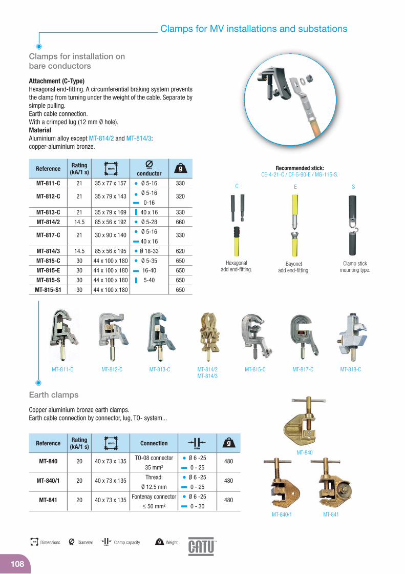
Clamps for MV installations and substations
Clamps for installation on bare conductors
108
EC S
Bayonet add end-fitting.
Clamp stickmounting type.
Recommended stick:CE-4-21-C / CF-5-90-E / MG-115-S.
MT-818-CMT-814/2MT-814/3
MT-815-C MT-817-CMT-813-CMT-812-CMT-811-C
MT-840/1
MT-840
MT-841
Earth clamps
Copper aluminium bronze earth clamps.Earth cable connection by connector, lug, TO- system...
MT-840
MT-840/1
MT-841
Reference Rating(kA/1 s)
20
20
20
TO-08 connector
35 mm2
Thread:
Ø 12.5 mm
Fontenay connector
≤ 50 mm2
Ø 6 -25
0 - 25
Ø 6 -25
0 - 25
Ø 6 -25
0 - 30
Connection
480
480
480
g
40 x 73 x 135
40 x 73 x 135
40 x 73 x 135
mmmm
Hexagonal add end-fitting.
MT-811-C
MT-812-C
MT-813-C
MT-814/2
MT-817-C
MT-814/3
MT-815-C
MT-815-E
MT-815-S
MT-815-S1
Reference Rating(kA/1 s)
21
21
21
14.5
21
14.5
30
30
30
30
330
320
330
660
330
620
650
650
650
650
g
35 x 77 x 157
35 x 79 x 143
35 x 79 x 169
85 x 56 x 192
30 x 90 x 140
85 x 56 x 195
44 x 100 x 180
44 x 100 x 180
44 x 100 x 180
44 x 100 x 180
mm mm
conductor
Attachment (C-Type)Hexagonal end-fitting. A circumferential braking system preventsthe clamp from turning under the weight of the cable. Separate bysimple pulling.Earth cable connection.With a crimped lug (12 mm Ø hole).MaterialAluminium alloy except MT-814/2 and MT-814/3:copper-aluminium bronze.
mmClamp capacitymm Dimensions g Weight
mmDiameter
Ø 5-16
Ø 5-16
0-16
40 x 16
Ø 5-28
Ø 5-16
40 x 16
Ø 18-33
Ø 5-35
16-40
5-40
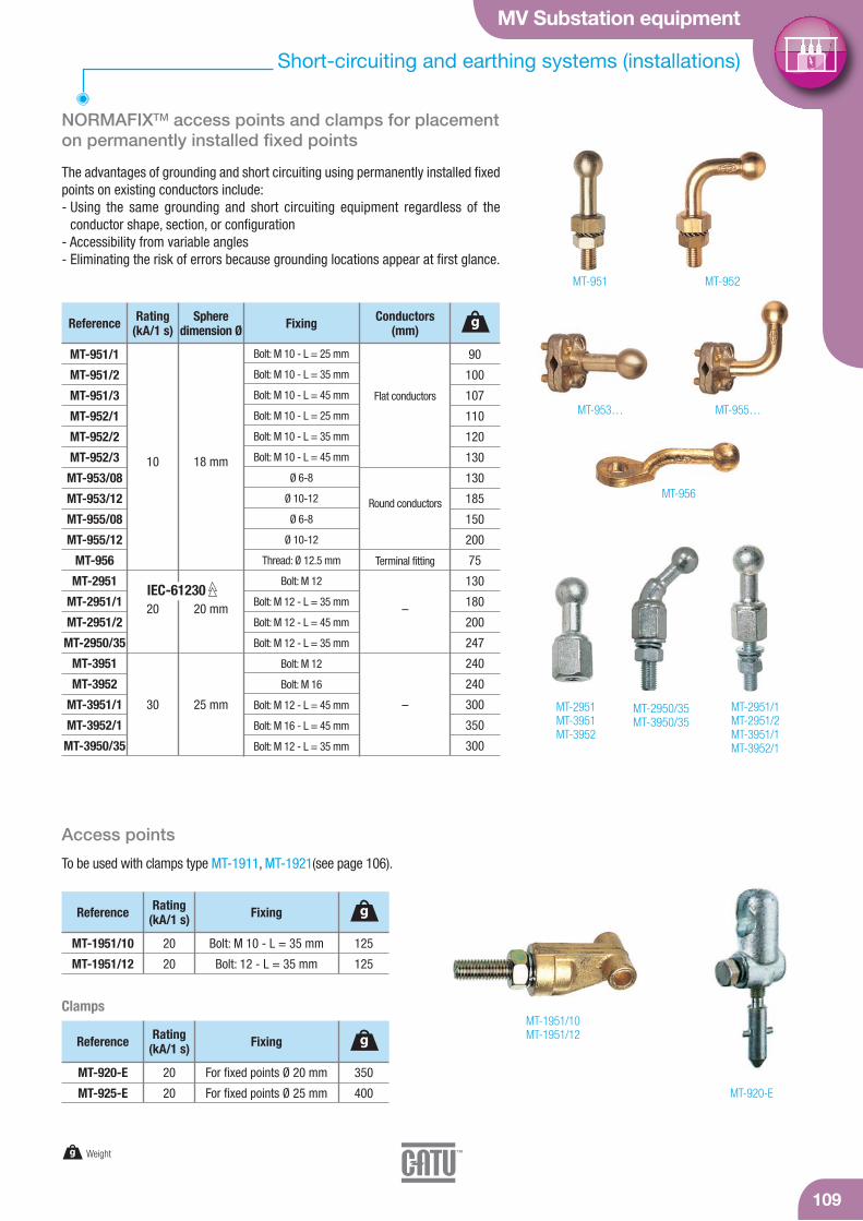
MV Substation equipment
109
Short-circuiting and earthing systems (installations)
NORMAFIXTM access points and clamps for placementon permanently installed fixed points
MT-955…MT-953…
MT-956
MT-2951/1MT-2951/2MT-3951/1MT-3952/1
MT-2951MT-3951MT-3952
MT-1951/10MT-1951/12
MT-920-E
MT-2950/35MT-3950/35
18 mm
20 mm
25 mm
MT-951/1
MT-951/2
MT-951/3
MT-952/1
MT-952/2
MT-952/3
MT-953/08
MT-953/12
MT-955/08
MT-955/12
MT-956
MT-2951
MT-2951/1
MT-2951/2
MT-2950/35
MT-3951
MT-3952
MT-3951/1
MT-3952/1
MT-3950/35
Reference Rating(kA/1 s)
10
20
30
Sphere dimension Ø
Bolt: M 10 - L = 25 mm
Bolt: M 10 - L = 35 mm
Bolt: M 10 - L = 45 mm
Bolt: M 10 - L = 25 mm
Bolt: M 10 - L = 35 mm
Bolt: M 10 - L = 45 mm
Ø 6-8
Ø 10-12
Ø 6-8
Ø 10-12
Thread: Ø 12.5 mm
Bolt: M 12
Bolt: M 12 - L = 35 mm
Bolt: M 12 - L = 45 mm
Bolt: M 12 - L = 35 mm
Bolt: M 12
Bolt: M 16
Bolt: M 12 - L = 45 mm
Bolt: M 16 - L = 45 mm
Bolt: M 12 - L = 35 mm
Flat conductors
Round conductors
Terminal fitting
–
–
Fixing Conductors(mm)
90
100
107
110
120
130
130
185
150
200
75
130
180
200
247
240
240
300
350
300
g
IEC-61230
The advantages of grounding and short circuiting using permanently installed fixedpoints on existing conductors include:- Using the same grounding and short circuiting equipment regardless of the
conductor shape, section, or configuration- Accessibility from variable angles- Eliminating the risk of errors because grounding locations appear at first glance.
MT-951 MT-952
Access points
To be used with clamps type MT-1911, MT-1921(see page 106).
MT-1951/10
MT-1951/12
Reference Rating(kA/1 s)
20
20
Bolt: M 10 - L = 35 mm
Bolt: 12 - L = 35 mm
Fixing
125
125
g
Clamps
MT-920-E
MT-925-E
Reference Rating(kA/1 s)
20
20
For fixed points Ø 20 mm
For fixed points Ø 25 mm
Fixing
350
400
g
g Weight

110
CF-3
Short-circuiting and earthing systems (installations)
IEC-61235**IEC-60855
CE-4-21-C
CE-75-C
CF-5
CM-7-10-A
Lower elementmade of resinpolyester/glassfiber. Ø 41 mm.
Telescopic stickcontains 2 ele-ments made ofresin polyester/glass fiber tube.
Lockableby button.
An upper orange element madeof glass fiber/resin epoxy foamfilled of 32 mm diameter (**). Isolating skirts
polycarbonate Ø 100 mm,height 90 mm ,shock resistant.
Element made of glass fiber/resinepoxy foam filled of 36 mm diameter.
Insulating sticks for substation use
Telescopic sticks for voltage detectors and earthing systems for usein dry and wet conditions.
CE-4-21-(*)
CM-7-10-A
CE-75-(*)
90 kV
Extension*
75 kV
41/32
36
41/32
1.15
–
1.15
2
1
2
1 500
1 000
1 200
(*) Specify type of mounting when ordering: C or K.Delivered with wall mounted support CI-10-D.
* For CE-4-21.
Referencemm
m gFolded m
Standard sticks
For short circuiting and earthing system.For use in dry conditions.
(*) Specify type of mounting when ordering: C, K or E.Delivered with wall mounted support CI-10-D.
CE-3-72-(*)
CE-3-90-(*)
72.5 kV
90 kV
36
36
1.50
2
880
1 060
Referencemm
gm
Sticks with skirts
Short length stick
For short circuiting and earthing system.For use in dry conditions.
(*) Specify type of mounting when ordering: C, K or E.
CF-5-40-(*)
CF-5-90-(*)
40 kV
90 kV
36
36
1.50
2
1 550
1 550
Referencemm
gm
CE-3-24-CInsulating Length = 0.52Overall Length = 0.80Folded Length = 0.56
Reference
370
g
For MV telescopic sticks.
CE-3-24-C
Terminal element in resine of polyester/glassfiber foam filled.
m
g Weightmm
Diameter mm Total length
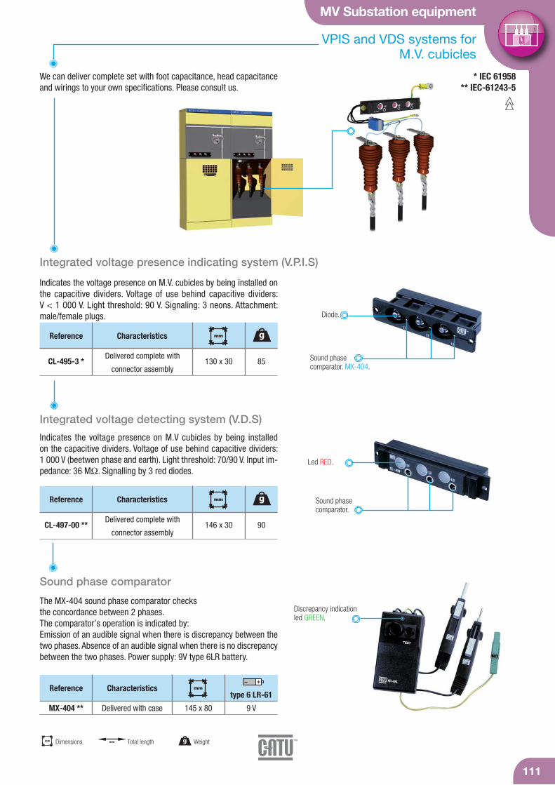
MV Substation equipment
111
g Weightmm Dimensions mm Total length
VPIS and VDS systems for M.V. cubicles
Integrated voltage presence indicating system (V.P.I.S)
Indicates the voltage presence on M.V. cubicles by being installed onthe capacitive dividers. Voltage of use behind capacitive dividers: V < 1 000 V. Light threshold: 90 V. Signaling: 3 neons. Attachment:male/female plugs.
We can deliver complete set with foot capacitance, head capacitanceand wirings to your own specifications. Please consult us.
* IEC 61958** IEC-61243-5
Sound phase comparator. MX-404.
Reference Characteristics
CL-495-3 *Delivered complete with
connector assembly85
g
130 x 30
mm
Diode.
Integrated voltage detecting system (V.D.S)
Indicates the voltage presence on M.V cubicles by being installed on the capacitive dividers. Voltage of use behind capacitive dividers: 1 000 V (beetwen phase and earth). Light threshold: 70/90 V. Input im-pedance: 36 MΩ. Signalling by 3 red diodes.
Sound phase comparator.
Led RED.
Sound phase comparator
The MX-404 sound phase comparator checks the concordance between 2 phases. The comparator’s operation is indicated by:Emission of an audible signal when there is discrepancy between thetwo phases. Absence of an audible signal when there is no discrepancybetween the two phases. Power supply: 9V type 6LR battery.
Discrepancy indicationled GREEN.
Reference Characteristics
CL-497-00 **Delivered complete with
connector assembly90
g
146 x 30
mm
Reference Characteristics
MX-404 ** Delivered with case 145 x 80
mm
9 V
type 6 LR-61
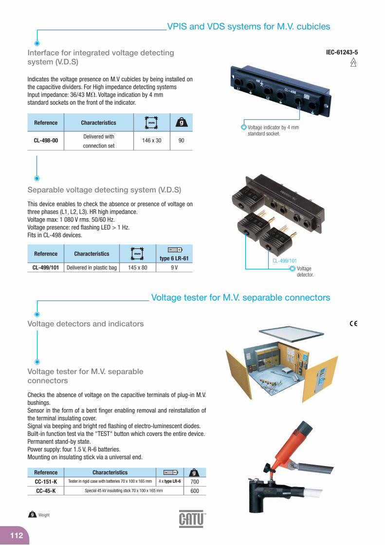
112
g Weight
VPIS and VDS systems for M.V. cubicles
Interface for integrated voltage detecting system (V.D.S)
Indicates the voltage presence on M.V cubicles by being installed onthe capacitive dividers. For High impedance detecting systemsInput impedance: 36/43 M. Voltage indication by 4 mm standard sockets on the front of the indicator.
Voltage indicator by 4 mm standard socket.
Separable voltage detecting system (V.D.S)
This device enables to check the absence or presence of voltage onthree phases (L1, L2, L3). HR high impedance.Voltage max: 1 080 V rms. 50/60 Hz. Voltage presence: red flashing LED > 1 Hz. Fits in CL-498 devices.
CL-499/101Reference Characteristics
CL-499/101 Delivered in plastic bag 145 x 80
mm
9 V
type 6 LR-61
Reference Characteristics
CL-498-00Delivered with
connection set90
g
146 x 30
mm
IEC-61243-5
Voltage detector.
Voltage tester for M.V. separable connectors
Voltage detectors and indicators
Voltage tester for M.V. separable connectors
Checks the absence of voltage on the capacitive terminals of plug-in M.V.bushings.Sensor in the form of a bent finger enabling removal and reinstallation ofthe terminal insulating cover.Signal via beeping and bright red flashing of electro-luminescent diodes.Built-in function test via the "TEST" button which covers the entire device.Permanent stand-by state.Power supply: four 1.5 V, R-6 batteries.Mounting on insulating stick via a universal end.
Reference Characteristics
CC-151-K
CC-45-K
Tester in rigid case with batteries 70 x 100 x 165 mm
Special 45 kV insulating stick 70 x 100 x 165 mm
700
600
g4 x type LR-6
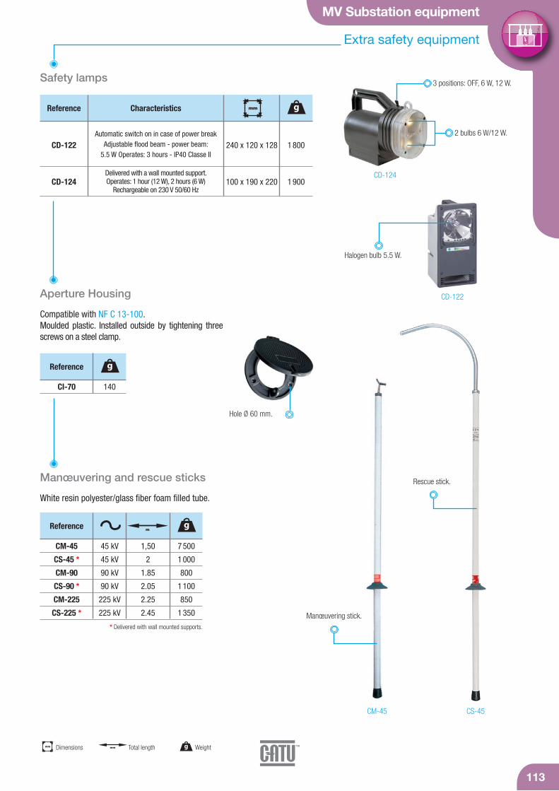
MV Substation equipment
113
Extra safety equipment
Safety lamps
Manœuvering and rescue sticks
White resin polyester/glass fiber foam filled tube.
Aperture Housing
Compatible with NF C 13-100.Moulded plastic. Installed outside by tightening threescrews on a steel clamp.
CD-122
CD-124
CS-45CM-45
Hole Ø 60 mm.
Halogen bulb 5.5 W.
2 bulbs 6 W/12 W.
3 positions: OFF, 6 W, 12 W.
Reference Characteristics
CD-122
CD-124
Automatic switch on in case of power breakAdjustable flood beam - power beam:
5.5 W Operates: 3 hours - IP40 Classe II
gmm
240 x 120 x 128
100 x 190 x 220
1 800
1 900
* Delivered with wall mounted supports.
CM-45
CS-45 *
CM-90
CS-90 *
CM-225
CS-225 *
45 kV
45 kV
90 kV
90 kV
225 kV
225 kV
1,50
2
1.85
2.05
2.25
2.45
7 500
1 000
800
1 100
850
1 350
Reference gm
CI-70 140
Reference g
Manœuvering stick.
Rescue stick.
g Weightmm Dimensions mm Total length
Delivered with a wall mounted support. Operates: 1 hour (12 W), 2 hours (6 W)
Rechargeable on 230 V 50/60 Hz

114
Extra safety equipment and life saving kits
For sticks and voltage detectors. Plastic.
Wall mounted supports
CI-06-D
CI-08
CI-10-D
28-30
16-20
32-36
Reference mm
Top
36 max.
36 max.
58 max.
mm
Bottom
Delivered with wood screws.
Top Bottom
Rescue hook
* Delivered with small mounted supports and 4 screws.
Reference Characteristics
CS-01-C Adaptor C 350
g
345 x 335
mm
On stick equippedwith a "C" end-fitting.
g Weightmm Dimensionsmm
Diameter
Compact carrying KIT
This compact kit is designed especially to be carried in a vehicle forsafety electrical intervention.Made in two part (of moulded material: PEHD), the case is also on itsred part, an insulating platform.
Reference Characteristics with instructions in English
CZ-53-R
CZ-53-MR
CZ-53-R/2
CZ-53-MR/2
With instructions in English
With instructions in English/Arabic
With instructions in English
With instructions in English/Arabic
21 000
21 000
21 000
21 000
g
710 x 570 x 240
710 x 570 x 240
710 x 570 x 240
710 x 570 x 240
mm
25 kV
25 kV
36 kV
36 kV
Insulating platform.
Telescopic insulatingstick.
Voltage detector with autotest.Rescue hook.
Insulated cutter cable.
Pair of insulatinggloves.
Talcum powder can.
Adhesive tape(black and yellow).
Safety instructions and safetyfirst aid posters.
Pair of insulatingboots.
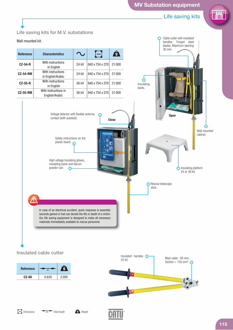
Close
MV Substation equipment
Life saving kits
115
Wall mounted kit.
In case of an electrical accident, quick response is essential:seconds gained or lost can decide the life or death of a victim.Our life saving equipment is designed to make all necessarymaterials immediately available to rescue personnel.
Life saving kits for M.V. substations
Open
Insulated cable cutterMaxi cable : 26 mm.Section ≈ 150 mm2.
CZ-60 0.630 2 200
Reference gm
Reference Characteristics
CZ-54-R
CZ-54-RM
CZ-55-R
CZ-55-RM
With instructionsin English
With instructions in English/ArabicWith instructions
in EnglishWith instructions in
English/Arabic
21 000
21 000
21 000
21 000
g
840 x 754 x 270
840 x 754 x 270
840 x 754 x 270
840 x 754 x 270
mm
24 kV
24 kV
36 kV
36 kV
Insulated handles25 kV.
Safety instructions on theplastic board.
Voltage detector with flexible antennacontact (with autotest).
Rescue telescopicstick.
Insulating platform24 or 36 kV.
Cable cutter with insulatedhandles. Forged steelblades. Maximum opening30 mm.
Wall mountedcabinet.
Insulatingboots.
High voltage Insulating gloves,insulating boots and talcumpowder can.
g Weightmm Dimensions mm Total length


IEC voltage detectors 118
Single phase comparators 120
Phase comparators 121
IEC equipment 122
Insulating sticks 123
Clamps 125
Overhead line systems 126
Cables 127
Underground systems 129
Sticks accessories 130
Medium voltage equipment

CC-875-C
CC-875-K
Robust housing.Weight of the detector: 450 gr.Size of the detector: Ø 59 x 270 mm.
CC-875-5,5/20-(*)
CC-875-10/30-(*)
CC-875-10/36-(*)
CC-875-11/33
50/60 Hz
50/60 Hz
50/60 Hz
50/60 Hz
118
IEC voltage detectors
IEC-61243-1IEC electronic Voltage Detectors, "Compactserie" for indoor and outdoor use
Ultimate technology of voltage detector “Head Capacitive Technology"Compact and light, it offers a wide band (10/36 kV).Operating check:By pressing the TEST button:- A red LED flashes on.- Powerful rated audible signal > 60 dB(A)/2 m.- When loosening the button. The timed green LED lights up. While remaining
on, it indicates the good working order of the detector.Characteristics:- Precise and stable operating threshold.- High environmental resistance (impacts, vibrations, moisture).- Temperature conditions: class N (IEC -61243-1 standard).- Use from 50 to 60 Hz.
ReferenceOperating voltage (KV)
5.5 - 20 kV
10 - 30 kV
10 - 36 kV
11 - 33 kV
(*) Specify type of mounting when ordering: C or K.Packaging: unit supplied complete in a case with batteries and contact electrodes (straight and V-shaped).
Total weight: 1100 g. Total size: 340 x 275 x 83 mm. For other voltages, please consult us.
Voltage presence is indicated by:- red flashing LED (very bright -visible at more than 20 m
in direct lighting),- powerful rated audible signal > 60 dB(A)/2 m.
Contact electrodes fitted to thehousing by screwing and are easily interchangeable.
9 V
9 V
9 V
9 V
450
450
450
450
gtype 6 LR 61
C K
End fittings:C: hexagonal 12 mm, for hexagonal end-fitting sticks, K: universal, for universal end-fitting sticks.Recommended stick: CE-4-21, CE-75. See page 123.
g Weight
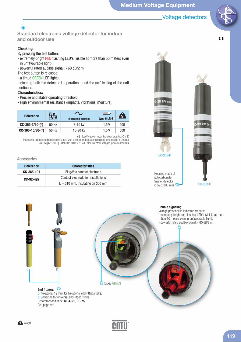
Medium Voltage Equipment
Voltage detectors
119
Standard electronic voltage detector for indoorand outdoor use
CheckingBy pressing the test button:- extremely bright RED flashing LED’s (visible at more than 50 meters even
in unfavourable light),- powerful rated audible signal > 60 dB/2 mThe test button is released:- a timed GREEN LED lights. Indicating both the detector is operational and the self testing of the unitcontinues.Characteristics:- Precise and stable operating threshold.- High environmental resistance (impacts, vibrations, moisture).
CC-363-K
CC-363-C
Double signaling:Voltage presence is indicated by both:- extremely bright red flashing LED’s (visible at more
than 50 meters even in unfavourable light),- powerful rated audible signal > 60 dB/2 m.
Housing made of polycarbonate.Size of detectorØ 59 x 390 mm.
CC-365-101
CC-92-492
Reference Characteristics
Flag/Vee contact electrode
Contact electrode for installations
L = 310 mm, insulating on 300 mm
Diode GREEN.
CC-365-3/10-(*)
CC-365-10/30-(*)
50 Hz
50 Hz
Reference
3-10 kV
10-30 kV
(*) Specify type of mounting when ordering: C or K.Packaging: unit supplied complete in a case with batteries and contact electrodes (straight and V-shaped).
Total weight: 1100 g. Total size: 340 x 275 x 83 mm. For other voltages, please consult us.
1.5 V
1.5 V
500
500
Accessories
C K
End fittings:C: hexagonal 12 mm, for hexagonal end-fitting sticks, K: universal, for universal end-fitting sticks.Recommended stick: CE-4-21, CE-75. See page 123.
g Weight
(operating voltage)g
type 6 LR 61
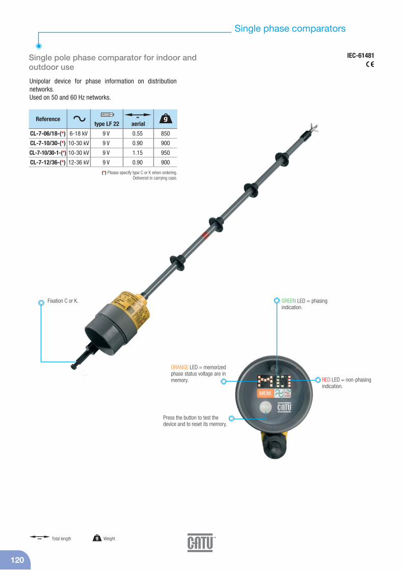
Single phase comparators
IEC-61481
120
Unipolar device for phase information on distribution networks.Used on 50 and 60 Hz networks.
Single pole phase comparator for indoor andoutdoor use
Press the button to test the device and to reset its memory.
CL-7-06/18-(*)
CL-7-10/30-(*)
CL-7-10/30-1-(*)
CL-7-12/36-(*)
6-18 kV
10-30 kV
10-30 kV
12-36 kV
0.55
0.90
1.15
0.90
9 V
9 V
9 V
9 V
(*) Please specify type C or K when ordering.Delivered in carrying case.
Reference m
aerialtype LF 22
GREEN LED = phasingindication.
Fixation C or K.
RED LED = non-phasingindication.
ORANGE LED = memorizedphase status voltage are inmemory.
850
900
950
900
g
g Weightmm Total length
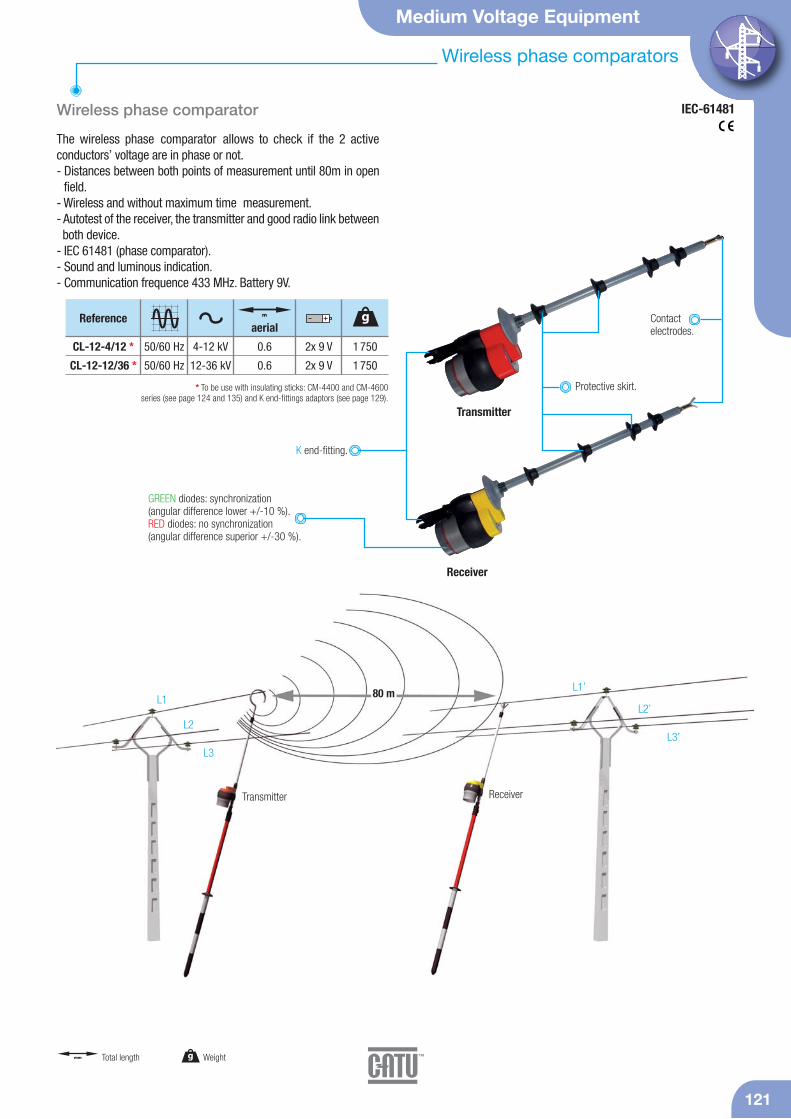
GREEN diodes: synchronization (angular difference lower +/-10 %). RED diodes: no synchronization(angular difference superior +/-30 %).
Medium Voltage Equipment
121
Wireless phase comparators
IEC-61481
Receiver
Transmitter
Wireless phase comparator
The wireless phase comparator allows to check if the 2 activeconductors’ voltage are in phase or not.- Distances between both points of measurement until 80m in open
field.- Wireless and without maximum time measurement.- Autotest of the receiver, the transmitter and good radio link between both device.
- IEC 61481 (phase comparator).- Sound and luminous indication.- Communication frequence 433 MHz. Battery 9V.
ReceiverTransmitter
L1
L2
L3
L1’
L2’
L3’
80 m
Contact electrodes.
K end-fitting.
CL-12-4/12 *
CL-12-12/36 *
4-12 kV
12-36 kV
0.6
0.6
2x 9 V
2x 9 V
* To be use with insulating sticks: CM-4400 and CM-4600 series (see page 124 and 135) and K end-fittings adaptors (see page 129).
Reference
1 750
1 750
g
50/60 Hz
50/60 Hz
aerial
Protective skirt.
g Weightmm Total length
m
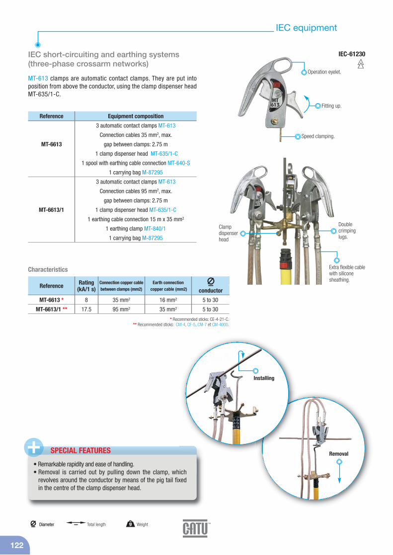
122
IEC equipment
IEC short-circuiting and earthing systems(three-phase crossarm networks)
MT-613 clamps are automatic contact clamps. They are put into position from above the conductor, using the clamp dispenser head MT-635/1-C.
IEC-61230
SPECIAL FEATURES+• Remarkable rapidity and ease of handling.• Removal is carried out by pulling down the clamp, which
revolves around the conductor by means of the pig tail fixedin the centre of the clamp dispenser head.
MT-6613
MT-6613/1
Reference Equipment composition
3 automatic contact clamps MT-613
Connection cables 35 mm2, max.
gap between clamps: 2.75 m
1 clamp dispenser head MT-635/1-C
1 spool with earthing cable connection MT-640-S
1 carrying bag M-87295
3 automatic contact clamps MT-613
Connection cables 95 mm2, max.
gap between clamps: 2.75 m
1 clamp dispenser head MT-635/1-C
1 earthing cable connection 15 m x 35 mm2
1 earthing clamp MT-840/1
1 carrying bag M-87295
Operation eyelet.
Removal
Fitting up.
Speed clamping.
C lamp dispenser head
Extra flexible cablewith siliconesheathing.
Double crimpinglugs.
Installing
g Weightmm
Diametermm
Diameter mm Total length
* Recommended sticks: CE-4-21-C.** Recommended sticks: CM-4, CF-5, CM-7 et CM-4000.
MT-6613 *
MT-6613/1 **
Reference Rating(kA/1 s)
8
17.5
Connection copper cablebetween clamps (mm2)
35 mm2
95 mm2
16 mm2
35 mm2
5 to 30
5 to 30
Earth connectioncopper cable (mm2)
mm
conductor
Characteristics
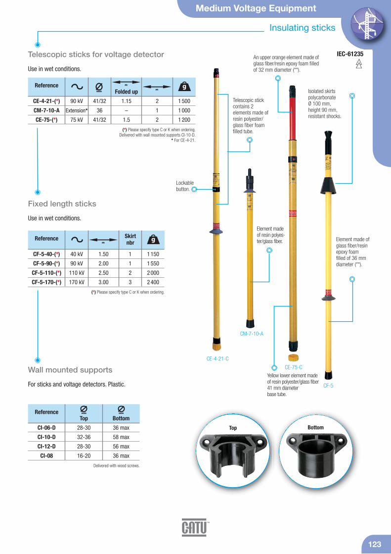
IEC-61235
Medium Voltage Equipment
123
Insulating sticks
Telescopic sticks for voltage detector
Use in wet conditions.
CE-4-21-C
CE-75-C
CF-5
CM-7-10-A
Yellow lower element madeof resin polyester/glass fiber41 mm diameter base tube.
For sticks and voltage detectors. Plastic.
Wall mounted supports
CE-4-21-(*)
CM-7-10-A
CE-75-(*)
90 kV
Extension*
75 kV
41/32
36
41/32
1.15
–
1.5
2
1
2
1 500
1 000
1 200
(*) Please specify type C or K when ordering.Delivered with wall mounted supports CI-10-D.
* For CE-4-21.
Telescopic stickcontains 2 elements made ofresin polyester/glass fiber foamfilled tube.
Lockable button.
Element madeof resin polyes-ter/glass fiber.
Referencemm
m gFolded up m Isolated skirts
polycarbonate Ø 100 mm,height 90 mm ,resistant shocks.
Fixed length sticks
Use in wet conditions.
CF-5-40-(*)
CF-5-90-(*)
CF-5-110-(*)
CF-5-170-(*)
40 kV
90 kV
110 kV
170 kV
1.50
2.00
2.50
3.00
1 150
1 550
2 000
2 400
1
1
2
3
(*) Please specify type C or K when ordering.
Reference gm
Skirtnbr
CI-06-D
CI-10-D
CI-12-D
CI-08
28-30
32-36
28-30
16-20
Reference mm
Top
36 max
58 max
56 max
36 max
mm
Bottom
Delivered with wood screws.
Element made ofglass fiber/resinepoxy foam filled of 36 mmdiameter (**).
An upper orange element made ofglass fiber/resin epoxy foam filledof 32 mm diameter (**).
Top Bottom
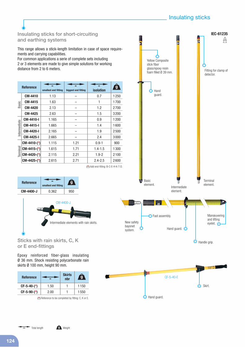
IEC-61235
124
CM-4400-J
Insulating sticks for short-circuiting and earthing systems
This range allows a stick-length limitation in case of space require-ments and carrying capabilities.For common applications a serie of complete sets including2 or 3 elements are made to give simple solutions for workingdistance from 2 to 6 meters.
Sticks with rain skirts, C, K or E end-fittings
Epoxy reinforced fiber-glass insulating Ø 36 mm. Shock resisting polycarbonate rainskirts Ø 100 mm, height 90 mm.
CF-5-40-E
New safetybayonetsystem. Hand guard.
Manœuveringand lifting eyelet.
Fitting for clamp ofdetector.
Fast assembly.
Intermediate elements with rain skirts.
Intermediateelement.
Basic element.
Terminalelement.
Hand guard.
Skirt.CF-5-40-(*)
CF-5-90-(*)
1.50
2.00
1 150
1 550
1
1
(*) Reference to be completed by fitting: C, K or E.
gm
Skirtsnbr
1 250
1 700
2 700
3 200
1 200
1 600
2 500
3 000
900
1 300
2 100
2 600
g
CM-4410
CM-4415
CM-4420
CM-4425
CM-4410-I
CM-4415-I
CM-4420-I
CM-4425-I
CM-4410-(*)
CM-4415-(*)
CM-4420-(*)
CM-4425-(*)
1.13
1.63
2.13
2.63
1.165
1.665
2.165
2.665
1.115
1.615
2.115
2.615
m
smallest end fitting
–
–
–
–
–
–
–
–
1.21
1.71
2.21
2.71
m
biggest end fitting
0.7
1
1.2
1.5
0.9
1.4
1.9
2.4
0.9-1
1.4-1.5
1.9-2
2.4-2.5
m
isolation
Basi
cIn
term
edia
teTe
rmin
al
(*) Add end-fitting: B-C-E-H-K-T-D.
950
Reference g
CM-4400-J 0.362
m
smallest end fitting
Insulating sticks
Handguard.
Handle grip.
Reference
Reference
g Weightmm Total length
Yellow Compositestick fiberglass/epoxy resinfoam filled Ø 39 mm.
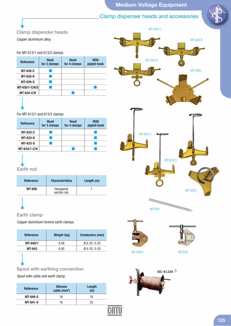
Medium Voltage Equipment
Clamp dispenser heads and accessories
125
Reference Headfor 3 clamps
Headfor 4 clamps
Withpigtail hook
MT-633-C
MT-633-K
MT-633-S
MT-634/1-C/K
Reference Silicone cable (mm2)
Length (m)
MT-640-S 16 16
MT-641-S 16 25
Reference Weight (kg) Conductors (mm)
MT-840/1 0.48 Ø 6-25 0-25
MT-843 0.95 Ø 6-35 0-35MT-840/1 MT-843
MT-630-C
MT-633-C
MT-633/..
MT-633-S
MT-630-S
Clamp dispender heads
Copper aluminium alloy.
Earth clamp
Copper aluminium bronze earth clamps.
Reference Characteristics Length (m)
MT-650 Hexagonal 1section rod
Earth rod
For MT-613/1 and 613/2 clamps
MT-650
Spool with earthing connection
Spool with cable and earth clamp.IEC-61230
Reference Headfor 3 clamps
Headfor 4 clamps
Withpigtail hook
MT-630-C
MT-630-K
MT-630-S
MT-635/1-C/K/S
MT-634-C/K
For MT-613/1 and 613/2 clamps
MT-630-K
MT-630/..
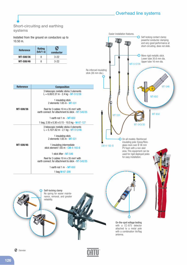
126
Overhead line systems
Short-circuiting and earthing systems
Installed from the ground on conductors up to10.50 m.
MT-546
MT-650
On-the-spot voltage testingwith a CC-875 detector attached to a metal polewith a combination Ve/flagantenna.
MT-508/36
MT-508/46
Reference Rating(kA/1 s)
8
8
3-22
3-22
mm
conductor
Composition
3 telescopic metallic sticks 3 elementsL = 6.00/2.37 m - 2.4 kg - MT-512/36
1 insulating stick 2 elements 1.65 m - MT-531
Reel for 3 cables 10 m x 35 mm2 withearth connect. for attachment to stick - MT-543/35
1 earth rod 1 m - MT-650
1 bag. 2.50 x 0.30 x 0.15 - 10.5 kg - M-87-127
3 telescopic metallic sticks 4 elementsL = 5.10/1.62 m - 2.1 kg - MT-512/46
1 insulating stick2 elements 1.65 m - MT-531
1 insulating intermediatestick element 1.65 m - CM-4-165-B
1 stick lifter - MT-546
Reel for 3 cables 10 m x 35 mm2 withearth connect. for attachment to stick - MT-543/35
1 earth rod 1 m - MT-650
1 bag M-87-208
Reference
MT-508/36
MT-508/46
MT-512/36
MT-531
CM-4-165-B
MT-543/35
MT-650
Easier installation features.Self locking contact clamp: powerful conductor clampingand very good performance atshort-circuiting, does not slide.
Re-inforced insulatingstick (36 mm dia.).
More rigid metallic stick.Lower tube 30.6 mm dia.Upper tube 16 mm dia.
On all models: Reinforced insulating pole: Epoxy/fibre-glass resin over Ø 36 mmPV foam with a non-skidarea. This equipment can beused for rigid deployed polesfor easy installation.
Self-locking clampNo spring for easier mainte-nance, removal, and greaterreliability.
mmDiameter

Medium Voltage Equipment
127
Cables
* IEC-61230Copper cables
Extra flexible braided multi-strand cables. Transparent PVC sheath, withcable section identification. Transparent silicon sheath according toIEC-61230. Resistant to temperature variations (-40 °C to +70 °C) withdouble IEC triangle marked on cable section.
Copper cables only: Heating curves (Gut & Grundberg method).
Copper cables only: Heating curves - 300 °C.
FUSI ÓN
500100015002000
10
16
25
30
35
40
50
70
95
3000
4000
5000
6000
7000
8000
9000
10. 000
15. 000
20. 000
25. 000
30. 000
35. 000
40. 000
0 0, 5 1 2 3 4 5sA
120 mm2
300°C
500100015002000 10
16
2530
40
50
70
95
3000
4000
5000
6000
7000
8000
9000
10. 000
15. 000
20. 000
25. 000
30. 000
35. 000
40. 000
0 0, 5 1 2 3 4 5s
0 0, 5 1 2 3 4 5s
A
120 mm2
35
Fusion 300 °C
M-24-10
M-24-16
M-24-25
M-24-30
M-24-35
M-24-40
M-24-50
M-24-70
M-24-75
M-24-95
M-24-120
M-24-150
–
M-24-16-S
M-24-25-S
–
M-24-35-S
M-24-40-S
M-24-50-S
M-24-70-S
–
M-24-95-S
M-24-120-S
M-24-150-S
Reference
A B*Rating
(kA/1 s)Cable
Weight (kg/m) Ø (mm)
2
3.5
6
7
8
10
12
16
20
20
30
40
0.105
0.156
0.5
0.330
0.86
0.440
0.545
0.768
0.800
1.000
1.280
1.630
4.5
5.6
7.5
8
9
9.5
10
12
12
14
17
19
Section(mm2)
10
16
25
30
35
40
50
70
75
95
120
150
Copper cables.
A: Transparent PVC sheath, with cable section identification.B: Transparent silicon sheath according to IEC-61230. Resistant to temperature variations
(-40 °C to +70 °C) with double IEC triangle marked on cable section.
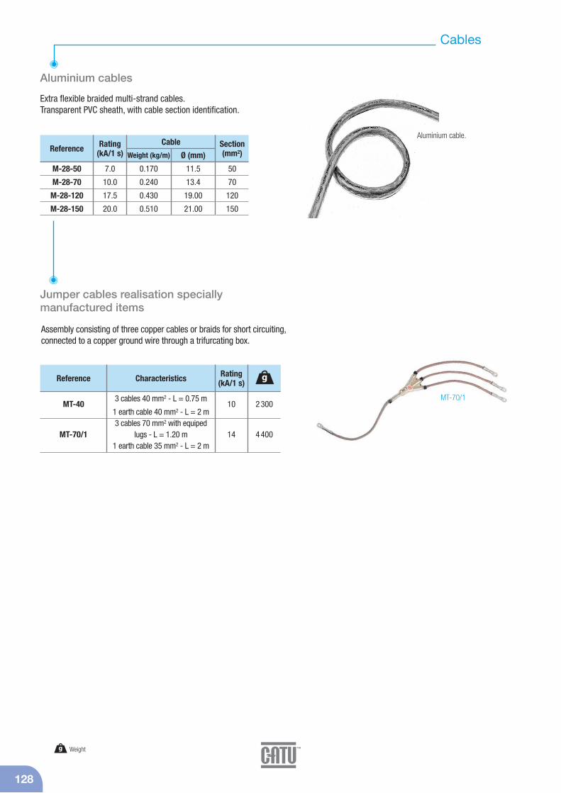
128
Cables
Aluminium cables
Extra flexible braided multi-strand cables.Transparent PVC sheath, with cable section identification.
MT-70/1
Jumper cables realisation specially manufactured items
Assembly consisting of three copper cables or braids for short circuiting,connected to a copper ground wire through a trifurcating box.
M-28-50
M-28-70
M-28-120
M-28-150
Reference Rating(kA/1 s)
Cable
Weight (kg/m) Ø (mm)
7.0
10.0
17.5
20.0
0.170
0.240
0.430
0.510
11.5
13.4
19.00
21.00
Section(mm2)
50
70
120
150
MT-40
MT-70/1
Reference Characteristics
3 cables 40 mm2 - L = 0.75 m
1 earth cable 40 mm2 - L = 2 m3 cables 70 mm2 with equiped
lugs - L = 1.20 m1 earth cable 35 mm2 - L = 2 m
Rating(kA/1 s)
10
14
2 300
4 400
g
Aluminium cable.
g Weight
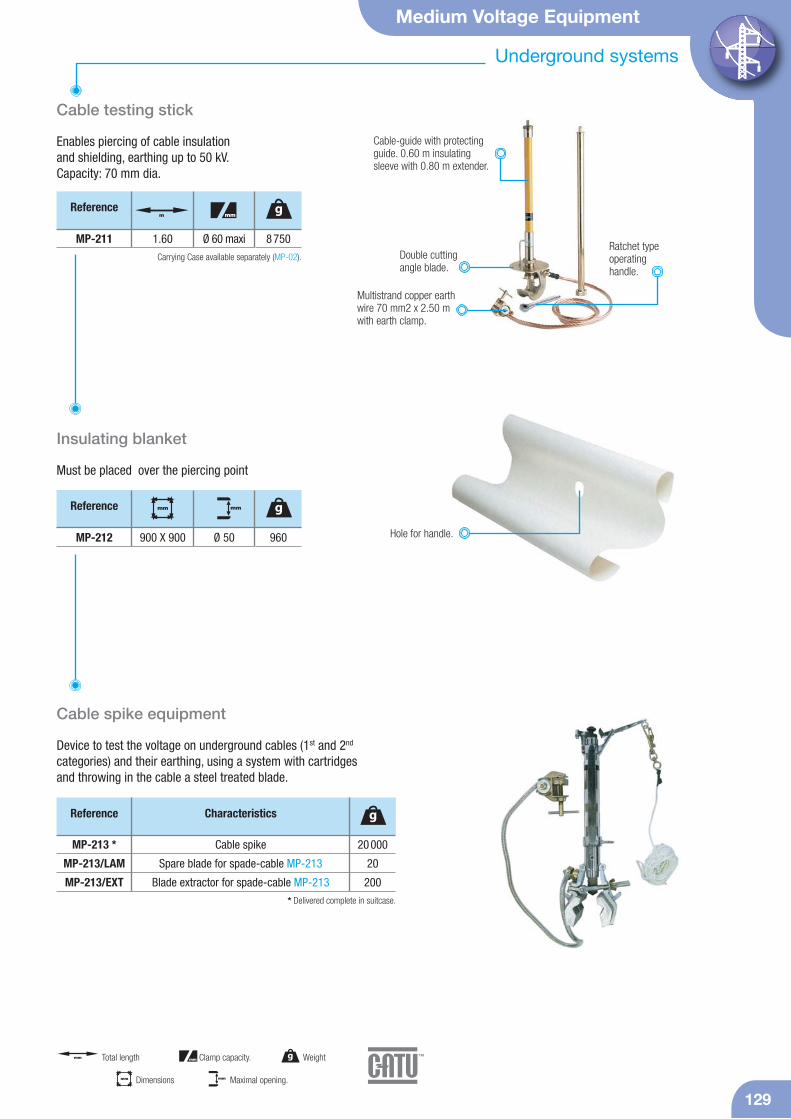
Medium Voltage Equipment
129
Underground systems
Cable testing stick
Enables piercing of cable insulation and shielding, earthing up to 50 kV.Capacity: 70 mm dia.
Carrying Case available separately (MP-02).Ratchet typeoperatinghandle.
MP-211 1.60 8 750Ø 60 maxi
Reference gm mm
Double cuttingangle blade.
Cable-guide with protectingguide. 0.60 m insulatingsleeve with 0.80 m extender.
Must be placed over the piercing point
Insulating blanket
960
Reference g
MP-212 Hole for handle.
mm
900 X 900 Ø 50
mm
Cable spike equipment
Device to test the voltage on underground cables (1st and 2nd
categories) and their earthing, using a system with cartridges and throwing in the cable a steel treated blade.
Cable spike
Spare blade for spade-cable MP-213
Blade extractor for spade-cable MP-213
Reference Characteristics
20 000
20
200
g
MP-213 *
MP-213/LAM
MP-213/EXT* Delivered complete in suitcase.
Multistrand copper earth wire 70 mm2 x 2.50 m with earth clamp.
g Weightmm Total length mm Clamp capacity.
mm Dimensions mm Maximal opening.

130
Sticks accessories
E
Connection adaptors for insulating sticks
Acce
ssor
ies
Conn
ectio
n ad
apto
rsSt
icks
C K S A ou B
C EK
CI-7-C CI-3-C CI-6-C CI-5-C CI-3-K CI-4-K CI-6-K CI-7-K CI-5-K CI-3-E CI-7-E CI-4-E
E A B K S A B C K E S A B K C
21
With this range any accessory can be attached to any stick by using connection adaptors. Other models, please consult us.
hexagonal universal bayonet clamp-stick"MAJOR" Serie CM-4 / CM-6.

Medium Voltage Equipment
131
Sticks accessories
Manœuvering hook
Bronze-copper nickel aluminium
Bronze-copper nickel aluminium
Reference Characteristics
120
120
g
CM-02-(*)
CM-03-K(*) Add end-fitting: C, E or K.
CM-02-C CM-03-KCM-02-K
Cleaning brushes
Trimmer and prunning saw
Fuse puller
All parts in metal protected against corrosion.
MD-12-C MD-14-C
MD-10-C
500
500
500
Reference g
MD-10-C
MD-12-C
MD-14-C
mm
100 x 125 x 170
175 x 228
175 x 328
Concave brush with two rows of perpendicular bristle
Round head brushAdjustable hinged round
head brush
Characteristics
1 200
1 100
–
Reference g
MD-40-B
MD-42-B
M-92-28
mm
375 x 240 x 60
125 x 610 x 60
–
Trimmer, maximum capacityØ 45 mm (for branches up to
28 mm depending on tree species)Prunning saw on rigid frame,
34 cm blade
Replacement blade MD-42-B
Characteristics
MD-40-B MD-42-B
CM-04-K
Reference
up to 70
mm
mm
230 x 80
g Weightmm
Diametermm Dimensions
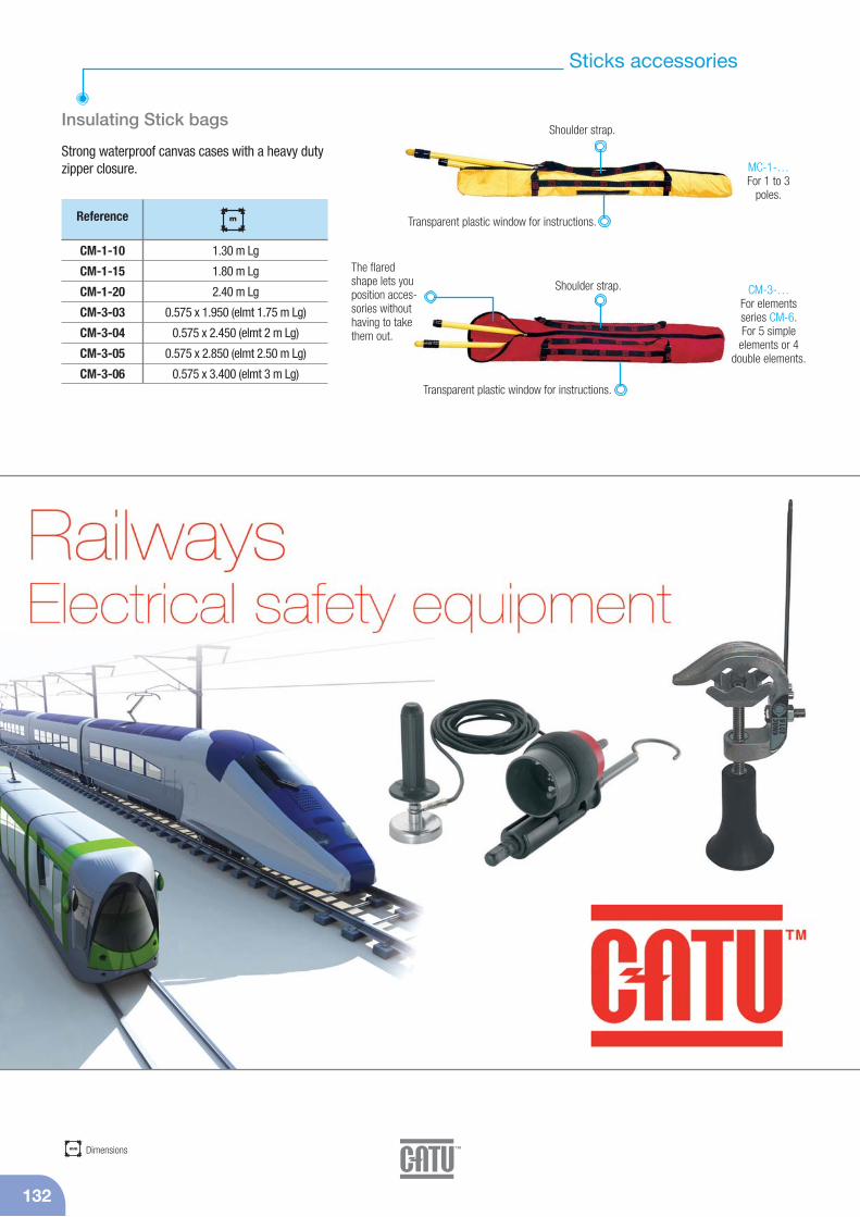
132
Sticks accessories
mm Dimensions
Insulating Stick bags
Strong waterproof canvas cases with a heavy dutyzipper closure.
Reference
CM-1-10
CM-1-15
CM-1-20
CM-3-03
CM-3-04
CM-3-05
CM-3-06
mm
1.30 m Lg
1.80 m Lg
2.40 m Lg
0.575 x 1.950 (elmt 1.75 m Lg)
0.575 x 2.450 (elmt 2 m Lg)
0.575 x 2.850 (elmt 2.50 m Lg)
0.575 x 3.400 (elmt 3 m Lg)
Shoulder strap.
The flaredshape lets youposition acces-sories withouthaving to takethem out.
Transparent plastic window for instructions.
Transparent plastic window for instructions.
Shoulder strap.
MC-1-…For 1 to 3
poles.
CM-3-…For elements series CM-6. For 5 simple
elements or 4double elements.
m

Voltage detectors 134
Insulating sticks 135
Clamps 136
Earthing system “APE” 137
Insulating sticks and earth clamps 138
Copper and aluminium cables 139
Accessories 140
HV lines and switchgearequipment

134
Voltage detectors
IEC 61243-1 edition 2Ac voltage detector for outdoor/indoor use
Precise and stable operating threshold. Insensitivity to inducedvoltages by limiting the operating voltage range. Remarkablyresistant to impacts, vibrations, extreme temperatures, humidity.Double signaling. Voltage presence indicated at the same time by:- 4 bright red flashing electro-luminescent diodes (visible at
more than 50 meters even in direct lighting),- a powerful rated acoustic signal (60 dB/2 m).
The CC-245 detectors are available according to the modelswith end fittings:W: Hexagonal 20 mm,C: Hexagonal 12 mm,K: Universal.Put on “silent block”.
CC-245-63/90-C
CC-245-150/420-K
K
C
Delivered in synthetic case with handle, battery and electrodes 370 x 165 x 145 mm.(*) Please specify type of mounting when ordering: C or K.
Robust housing made frompolycarbonate with highmechanical properties anddielectric strength.
CC-245-63/90-(*)
CC-245-150-(*)
CC-245-225/420-(*)
CC-245-60/150-(*)
CC-245-63/150-(*)
CC-245-90/225-(*)
CC-245-150/420-(*)
CC-245-225/550-(*)
CC-245-315/765-1-(*)
Reference IEC 61243-1edition 2
63 - 90 kV
150 kV
225 - 420 kV
60 - 150 kV
63 - 150 kV
90 - 225 kV
150 - 420 kV
225 - 550 kV
315 - 765 kV
Contact electrode
Ø 120 mm
Ø 120 mm
Ø 200 mm
Ø 120 mm
Ø 120 mm
Ø 120 mm
Ø 120 mm
Ø 200 mm
Ø 200 mm
Body colour
Yellow
Red
Red
Red
Red
Red
Red
Red
Red
9 V
9 V
9 V
9 V
9 V
9 V
9 V
9 V
9 V
-25/+55 C°
-25/+55 C°
-25/+55 C°
-25/+55 C°
-25/+55 C°
-25/+55 C°
-25/+55 C°
-25/+55 C°
-25/+55 C°
650
650
650
650
650
650
650
650
650
gtype 6 LR 61
•
•
•
•
•
•
•
–
–
(Operating voltage)
Surrounded by a rubber impact-resistant padding.
Two GREEN illuminated lights, indicatingthat the device is on. These lights turnoff, and four RED lights illuminate when a voltage is detected.
Check that the device is workingby pressing the TEST button. This tests all of the detector's active components once the TESTbutton is released.
g Weight
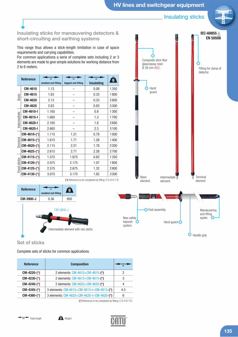
HV lines and switchgear equipment
Insulating sticks
135
CM-3900-J
Insulating sticks for manœuvering detectors &short-circuiting and earthing systems
This range thus allows a stick-length limitation in case of space requirements and carrying capabilities.For common applications a serie of complete sets including 2 or 3 elements are made to give simple solutions for working distance from2 to 6 meters.
New safetybayonetsystem.
Hand guard.
Handle grip.
Manœuveringand lifting eyelet.
Composite stick fiberglass/epoxy resin Ø 39 mm RED.
Handguard.
Fitting for clamp ofdetector.
Fast assembly.
Intermediate element with rain skirts.
Intermediateelement.
Basic element.
Terminalelement.
950
Reference g
CM-3900-J 0.36
m
smallest end fitting
Set of sticks
Complete sets of sticks for common applications.
1 350
1 800
2 800
3 300
1 300
1 700
2 600
3 100
1 000
1 400
2 200
2 700
1 350
1 800
2 800
3 300
Reference g
CM-4610
CM-4615
CM-4620
CM-4625
CM-4610-I
CM-4615-I
CM-4620-I
CM-4625-I
CM-4610-(*)
CM-4615-(*)
CM-4620-(*)
CM-4625-(*)
CM-4115-(*)
CM-4120-(*)
CM-4125-(*)
CM-4130-(*)
1.13
1.63
2.13
2.63
1.165
1.665
2.165
2.665
1.115
1.615
2.115
2.615
1.575
2.075
2.575
3.075
m
smallest end fitting
–
–
–
–
–
–
–
–
1.21
1.71
2.21
2.71
1.675
2.175
2.675
3.175
m
biggest end fitting
0.08
0.33
0.33
0.83
0.8
1.3
1.8
2.3
0.78
1.28
1.78
2.28
0.82
1.07
1.32
1.82
m
Insulating
Basi
cIn
term
edia
teTe
rmin
alFi
xed
stic
ks
(*) Reference to be completed by fitting: C-E-H-K-T-D.
m
CM-4220-(*)
CM-4230-(*)
CM-4240-(*)
CM-4345-(*)
CM-4360-(*)
Reference Composition
2 elements: CM-4610+CM-4610-(*)
2 elements: CM-4615+CM-4615-(*)
2 elements: CM-4620+CM-4620-(*)
3 elements: CM-4615+CM-4615-I+CM-4615-(*)
3 elements: CM-4620+CM-4620-I+CM-4620-(*)
2
3
4
4.5
6
(*) Reference to be completed by fitting: C-E-H-K-T-D.
IEC-60855EN 50508
g Weightmm Total length
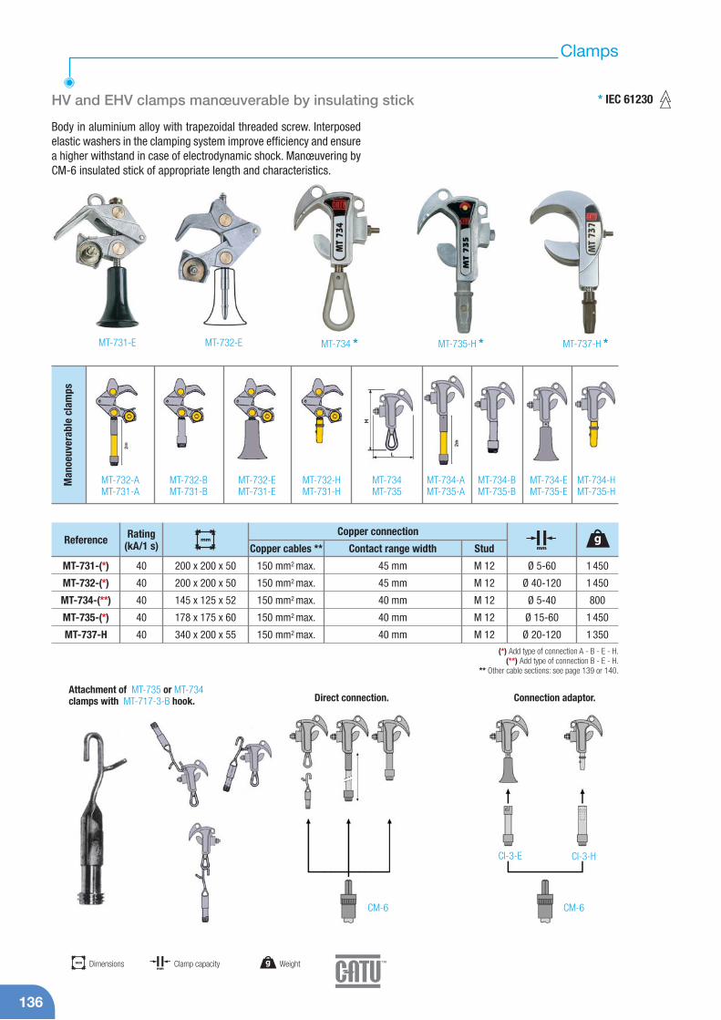
136
Clamps
HV and EHV clamps manœuverable by insulating stick
Body in aluminium alloy with trapezoidal threaded screw. Interposedelastic washers in the clamping system improve efficiency and ensurea higher withstand in case of electrodynamic shock. Manœuvering byCM-6 insulated stick of appropriate length and characteristics.
Attachment of MT-735 or MT-734clamps with MT-717-3-B hook. Direct connection. Connection adaptor.
CM-6 CM-6
CI-3-E CI-3-H
MT-731-E MT-732-E MT-734 * MT-735-H * MT-737-H *
Man
oeuv
erab
le c
lam
ps
MT-732-AMT-731-A
MT-732-BMT-731-B
MT-732-EMT-731-E
MT-732-HMT-731-H
MT-734MT-735
MT-734-AMT-735-A
MT-734-BMT-735-B
MT-734-EMT-735-E
MT-734-HMT-735-H
(*) Add type of connection A - B - E - H.(**) Add type of connection B - E - H.
** Other cable sections: see page 139 or 140.
MT-731-(*)
MT-732-(*)
MT-734-(**)
MT-735-(*)
MT-737-H
Reference Rating(kA/1 s)
40
40
40
40
40
150 mm2 max.
150 mm2 max.
150 mm2 max.
150 mm2 max.
150 mm2 max.
45 mm
45 mm
40 mm
40 mm
40 mm
M 12
M 12
M 12
M 12
M 12
Ø 5-60
Ø 40-120
Ø 5-40
Ø 15-60
Ø 20-120
Copper connection
Copper cables ** Contact range width Stud
1 450
1 450
800
1 450
1 350
g
200 x 200 x 50
200 x 200 x 50
145 x 125 x 52
178 x 175 x 60
340 x 200 x 55
mm
mm
g Weightmm Dimensionsmm
Clamp capacity
* IEC 61230

HV lines and switchgear equipment
137
Earthing system APE
Earthing system with clamp interlocking
The APE is a grounding system with an interlocking systembetween earthing clamp and line clamps. It is used for safeand accurate installation (earthing clamp and then lineclamp) and removal (line clamp and then earthing clamp).
MT-834-H*
MT-834-E*
MT-834-T*
MT-835-H*
MT-835-E*
MT-835-T*
MT-837-H*
MT-837-E*
MT-837-T*
MT-934*
MT-935*
Reference Rating Use
31.5 kA/1 s
31.5 kA/1 s
31.5 kA/1 s
31.5 kA/1 s
31.5 kA/1 s
31.5 kA/1 s
31.5 kA/1 s
31.5 kA/1 s
31.5 kA/1 s
31.5 kA/1 s
31.5 kA/1 s
Substation
Substation
Substation
Substation
Substation
Substation
Substation
Substation
Substation
Line
Line
Fitting
H hexagonal
E bayonet
T bayonet
H hexagonal
E bayonet
T bayonet
H hexagonal
E hexagonal
T hexagonal
ring
ring
5 - 40
5 - 40
5 - 40
15 - 60
15 - 60
15 - 60
20 - 120
20 - 120
20 - 120
5 - 40
15 - 60
9 600
9 600
9 600
10 440
10 440
10 440
11 640
11 640
11 640
9 600
10 440
g
360 x 200 x 85
360 x 200 x 85
360 x 200 x 85
390 x 200 x 85
390 x 200 x 85
390 x 200 x 85
470 x 220 x 85
470 x 220 x 85
470 x 220 x 85
360 x 200 x 85
390 x 200 x 85
mm
mm
width 38 mm
width 38 mm
width 38 mm
width 38 mm
width 38 mm
width 38 mm
width 38 mm
width 38 mm
width 38 mm
width 38 mm
width 38 mm
M 12
M 12
M 12
M 12
M 12
M 12
M 12
M 12
M 12
M 12
M 12
Connection
Range Stud
SPECIAL FEATURES+- Locking system using a patented system with
more than 30,000 possible combinations.- Easy installation and removal without additional
accessories.- Automatic trip at the recommended torque on
support withstand the short circuit current.- System security (unable to be unlocked without
the associated clamp).
Captive protection cap.
Earth clamp.
Clamping handle.
Clamp.
g Weightmm Dimensionsmm
Clamp capacity
*One reference including 3 phases, so 3 clamps equipped.
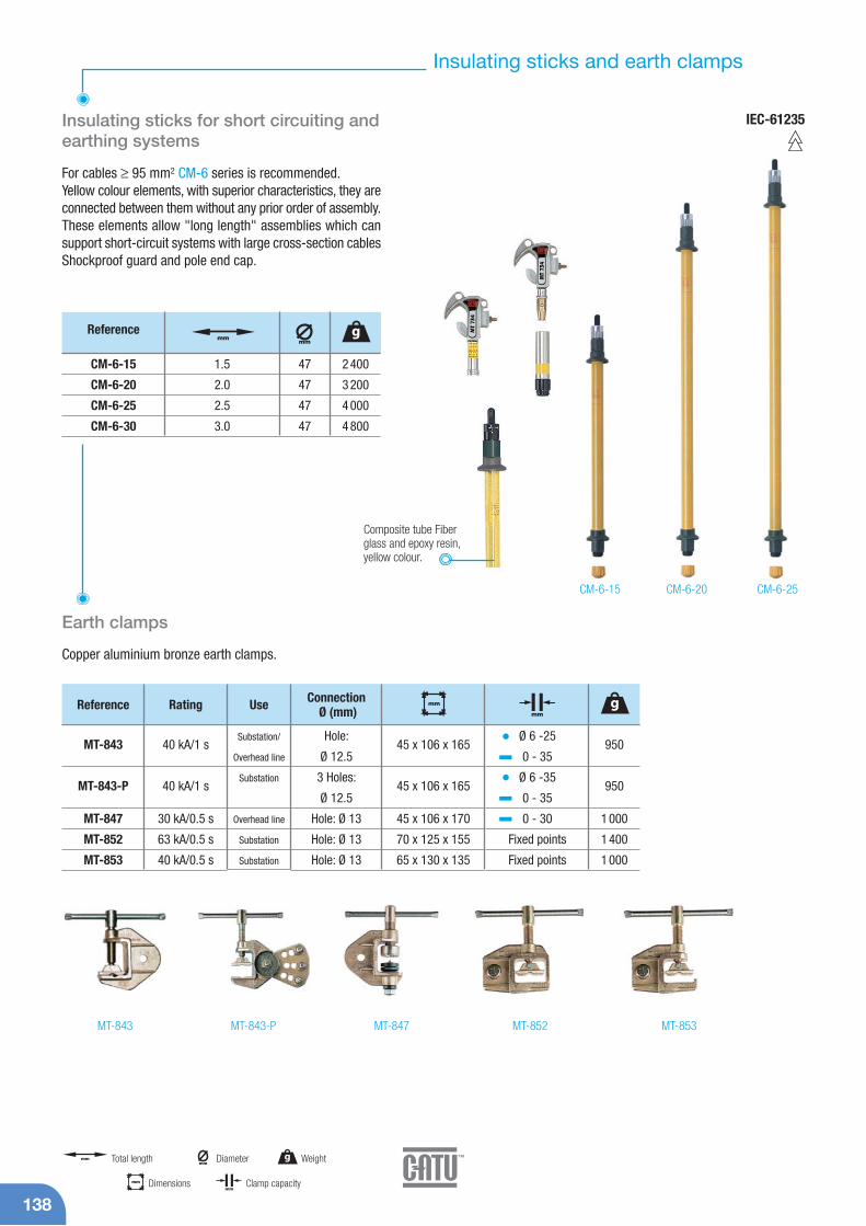
138
Insulating sticks and earth clamps
IEC-61235Insulating sticks for short circuiting and earthing systems
For cables ≥ 95 mm2 CM-6 series is recommended.Yellow colour elements, with superior characteristics, they areconnected between them without any prior order of assembly.These elements allow "long length" assemblies which cansupport short-circuit systems with large cross-section cablesShockproof guard and pole end cap.
CM-6-15 CM-6-20 CM-6-25
Composite tube Fiberglass and epoxy resin, yellow colour.
47
47
47
47
Referencemm
2 400
3 200
4 000
4 800
g
CM-6-15
CM-6-20
CM-6-25
CM-6-30
1.5
2.0
2.5
3.0
mm
Earth clamps
Copper aluminium bronze earth clamps.
MT-843 MT-847MT-843-P MT-852 MT-853
MT-843
MT-843-P
MT-847
MT-852
MT-853
Reference Rating Use
40 kA/1 s
40 kA/1 s
30 kA/0.5 s
63 kA/0.5 s
40 kA/0.5 s
Substation/
Overhead line
Substation
Overhead line
Substation
Substation
Hole:
Ø 12.5
3 Holes:
Ø 12.5
Hole: Ø 13
Hole: Ø 13
Hole: Ø 13
Ø 6 -25
0 - 35
Ø 6 -35
0 - 35
0 - 30
Fixed points
Fixed points
ConnectionØ (mm)
950
950
1 000
1 400
1 000
g
45 x 106 x 165
45 x 106 x 165
45 x 106 x 170
70 x 125 x 155
65 x 130 x 135
mm
mm
g Weightmm Total lengthmm
Diameter
mm Dimensionsmm
Clamp capacity
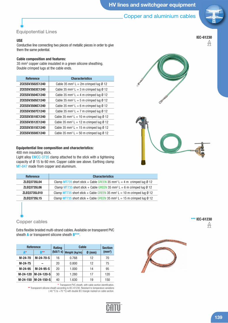
HV lines and switchgear equipment
139
Copper and aluminium cables
*** IEC-61230Copper cables
Extra flexible braided multi-strand cables. Available on transparent PVCsheath A or transparent silicone sheath B***.
IEC-61230
M-24-70
M-24-75
M-24-95
M-24-120
M-24-150
M-24-70-S
–
M-24-95-S
M-24-120-S
M-24-150-S
Reference
A* B**Rating
(kA/1 s)Cable
Weight (kg/m) Ø (mm)
16
20
20
30
40
0.768
0.800
1.000
1.280
1.630
12
12
14
17
19
Section(mm2)
70
75
95
120
150
* Transparent PVC sheath, with cable section identification.** Transparent silicone sheath according to IEC-61230. Resistant to temperature variations
(-40 °C to +70 °C) with double IEC triangle marked on cable section.
Equipotential Lines
USEConductive line connecting two pieces of metallic pieces in order to givethem the same potential.
Cable composition and features:35 mm2 copper cable insulated in a green silicone sheathing.Double crimped lugs at the cable ends.
Reference Characteristics
ZCESSV3502C1240
ZCESSV3503C1240
ZCESSV3504C1240
ZCESSV3505C1240
ZCESSV3506C1240
ZCESSV3507C1240
ZCESSV3510C1240
ZCESSV3512C1240
ZCESSV3515C1240
ZCESSV3550C1240
Cable 35 mm2 L = 2m crimped lug Ø 12
Cable 35 mm2 L = 3 m crimped lug Ø 12
Cable 35 mm2 L = 4 m crimped lug Ø 12
Cable 35 mm2 L = 5 m crimped lug Ø 12
Cable 35 mm2 L = 6 m crimped lug Ø 12
Cable 35 mm2 L = 7 m crimped lug Ø 12
Cable 35 mm2 L = 10 m crimped lug Ø 12
Cable 35 mm2 L = 12 m crimped lug Ø 12
Cable 35 mm2 L = 15 m crimped lug Ø 12
Cable 35 mm2 L = 50 m crimped lug Ø 12
Reference Characteristics
ZLEQ3735L04
ZLEQ3735L06
ZLEQ3735L010
ZLEQ3735L15
Clamp MT735 short stick + Cable GREEN 35 mm2 L = 4 m crimped lug Ø 12
Clamp MT735 short stick + Cable GREEN 35 mm2 L = 6 m crimped lug Ø 12
Clamp MT735 short stick + Cable GREEN 35 mm2 L = 10 m crimped lug Ø 12
Clamp MT735 short stick + Cable GREEN 35 mm2 L = 15 m crimped lug Ø 12
Equipotential line composition and characteristics:400 mm insulating stick.Light alloy EMCC-3735 clamp attached to the stick with a tighteningcapacity of Ø 15 to 60 mm. Copper cable see above. Earthing clampMT-847 made from copper and aluminum.

140
Accessories
Earthing kit support
Welded steel assembly with galvanization surfacetreatment.Writing zone available.
Reference
MT-895 900
g
230 x 230 x 150
mm
Reference Characteristics
MT-790
MT-792
MT-797
Copper/Alu alloy Ø 18 mm
Light alloy Ø 20 mm
Light alloy Ø 20 mm
1 400
855
1 200
gRating(kA/1 s)
30
30
30
Ø 12 - 60
Ø 12 - 60
Ø 60 - 120
255 x 105 x 50
270 x 105 x 60
240 x 170 x 60
mm
mm
Conductor
Copper
Aluminium
Aluminium
Type
Extra flexible braided multi-strand cables.Transparent PVC sheath, with cable section identification.
M-28-70
M-28-120
M-28-150
Reference Rating(kA/1 s)
Cable
Weight (kg/m) Ø (mm)
10.0
17.5
20.0
0.240
0.430
0.510
13.4
19.00
21.00
Section(mm2)
70
120
150
Aluminium cables
Adjustable access points
For large vertical or oblique heavy duty conductors.
g Weightmm
Diametermm Dimensions
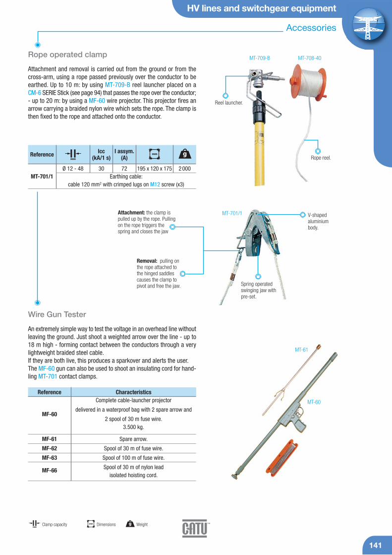
HV lines and switchgear equipment
141
Accessories
Rope operated clamp
Attachment and removal is carried out from the ground or from thecross-arm, using a rope passed previously over the conductor to beearthed. Up to 10 m: by using MT-709-B reel launcher placed on a CM-6 SERIE Stick (see page 94) that passes the rope over the conductor;- up to 20 m: by using a MF-60 wire projector. This projector fires anarrow carrying a braided nylon wire which sets the rope. The clamp isthen fixed to the rope and attached onto the conductor.
MT-708-40
MT-701/1
MT-709-B
Attachment: the clamp ispulled up by the rope. Pullingon the rope triggers thespring and closes the jaw
Wire Gun Tester
An extremely simple way to test the voltage in an overhead line withoutleaving the ground. Just shoot a weighted arrow over the line - up to18 m high - forming contact between the conductors through a verylightweight braided steel cable.If they are both live, this produces a sparkover and alerts the user.The MF-60 gun can also be used to shoot an insulating cord for hand-ling MT-701 contact clamps.
Reference Characteristics
MF-60
MF-61
MF-62
MF-63
MF-66
Complete cable-launcher projector
delivered in a waterproof bag with 2 spare arrow and
2 spool of 30 m fuse wire.3.500 kg.
Spare arrow.
Spool of 30 m of fuse wire.
Spool of 100 m of fuse wire.
Spool of 30 m of nylon leadisolated hoisting cord.
Earthing cable: cable 120 mm2 with crimped lugs on M12 screw (x3)
Reference
MT-701/12 000
gIcc(kA/1 s)
30
I assym.(A)
72 195 x 120 x 175
mm
Ø 12 - 48
mm
V-shaped aluminiumbody.
Spring operatedswinging jaw withpre-set.
Rope reel.
Reel launcher.
Removal: pulling onthe rope attached tothe hinged saddlescauses the clamp topivot and free the jaw.
MT-60
MT-61
g Weightmm Dimensionsmm
Clamp capacity

142
Accessories
Short-circuiting and earthingsystem carrying bags
Can receive earthing system equipment (clampsand cables).
M-87-295
M-87-53
Reference
M-87-53
M-87-153
M-87-295
2 000
2 500
1 500
g
380 x 250 x 400
380 x 250 x 600
550 x 300 x 300
mm
g Weightmm Dimensions

Earth rods 144
Connectors and earthing clip 145
Earth resistance tester 145
Earthing connections
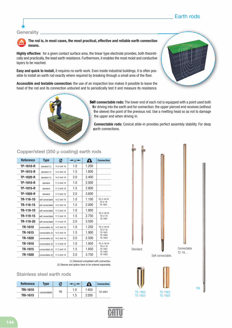
144
Earth rods
The rod is, in most cases, the most practical, effective and reliable earth connectionmeans.
Highly effective: for a given contact surface area, the linear type electrode provides, both theoreti-cally and practically, the least earth resistance. Furthermore, it enables the most moist and conductivelayers to be reached.
Easy and quick to install, it requires no earth work. Even inside industrial buildings, it is often pos-sible to install an earth rod exactly where required by breaking through a small area of the floor.
Accessible and testable connection: the use of an inspection box makes it possible to leave thehead of the rod and its connection unburied and to periodically test it and measure its resistance.
Generality
Self connectable rods: The lower end of each rod is equipped with a point used bothfor driving into the earth and for connection; the upper pierced end receives (withoutthe sleeve) the point of the previous rod. Use a rivetting head so as not to damagethe upper end when driving in.
Connectable rods: Conical slide-in provides perfect assembly stability. For deepearth connections.
Standard.
TS-1902TS-1602
TRITS-1903TS-1603
ConnectableTZ-16…
Self connectable.
(1) Delivered completed with connection.(2) Sleeves and spikes have to be ordered separately.
Reference Type
TRI-1610
TRI-1615
1.0
1.516 1 450
2 200TZI-2001
Stainless steel earth rods
Connectiongmm
mm
connectable
Reference Type
TP-1610-R
TP-1615-R
TP-1620-R
TP-1910-R
TP-1915-R
TP-1920-R
TR-116-10
TR-116-15
TR-119-10
TR-119-15
TR-119-20
TR-1610
TR-1615
TR-1620
TR-1910
TR-1915
TR-1920
1.0
1.5
2.0
1.0
1.5
2.0
1.0
1.5
1.0
1.5
2.0
1.0
1.5
2.0
1.0
1.5
2.0
14.2 Unit 16
14.2 Unit 16
14.2 Unit 16
17.3 Unit 19
17.3 Unit 19
17.3 Unit 19
14.2 Unit 16
14.2 Unit 16
17.3 Unit 19
17.3 Unit 19
17.3 Unit 19
14.2 Unit 16
14.2 Unit 16
14.2 Unit 16
17.3 Unit 19
17.3 Unit 19
17.3 Unit 19
1.200
1.800
2.400
2.000
2.800
3.600
1.100
2.000
1.800
2.750
3.500
1.250
1.900
2.500
1.950
1.850
3.750
Copper/steel (350 μ coating) earth rods
Connectiongmm
mm
standard (1)
standard (1)
standard (1)
standard
standard
standard
self connectable
self connectable
self connectable
self connectable
self connectable
connectable (2)
connectable (2)
connectable (2)
connectable (2)
connectable (2)
connectable (2)
TO-3-16/19 TO-2-19TS-1901TS-1902 TS-1903
TO-3-16/19TO-2-16 TS-1601TS-1602 TS-1603
TO-3-16/19TO-2-19 TS-1901
TO-3-16/19TO-2-16 TS-1601
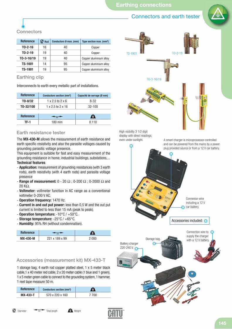
Earthing connections
145
g Weightmm
Diameter mm Total length
40
40
40
95
95
Copper
Copper
Copper aluminium alloy
Copper aluminium alloy
Copper aluminium alloy
Connectors and earth tester
TS-1901 TO-2-19
TO-3-16/19Earthing clip
Reference Rod
TO-2-16
TO-2-19
TO-3-16/19
TS-1601
TS-1901
16
19
19
14
19
Connectors
Conductors Ø max. (mm) Type section max. (mm2)
Interconnects to earth every metallic part of installations.
Earth resistance testerThe MX-430-M allows the measurement of earth resistance andearth specific resistivity and also the parasite voltages caused bygrounding parasitic voltage presence.This equipment is suitable for fast and easy measurement of thegrounding resistance in home, industrial buildings, substations,...Technical features- Application: measurement of grounding resistances (with 3 earth
rods), earth resistivity (with 4 earth rods) and parasite voltage presence
- Range of measurement: 0 - 20 Ω ; 0-200 Ω ; 0-2000 Ω and20 KΩ.
- Voltmeter: voltmeter function in AC range as a conventional voltmeter 0-200 V AC.
- Operation frequency: 1470 Hz.- Current in and out put power: less than 0,5 W and the out put
current is limited to less than 15 mA (peak to peak).- Operation temperature: -10°C / +50°C.- Storage temperature: -25°C / +65°C.- Humidity: 95% RH (without condemnation).
Accessories (measurement kit) MX-433-T
1 storage bag, 4 earth rod copper platted steel, 1 x 5 meter blackcable,1 x 40 meter red cable, 2 x 20 meter cable (1 blue and 1 green),1 x 5 meter green cable to connect to the grounding system, 1 hammer,1 reel tape measure 50 m.
Reference
TO-8/32
TO-32/100
1 x 2.5 to 2 x 6
1 x 2.5 to 2 x 16
8-32
32-100
Conductors section (mm2) Capacité de serrage (Ø mm)
High visibility 3 1/2 digitdisplay with direct readings,even under sunlight. A smart charger is microprocessor-controlled
and can be powered from the mains by a powerplug provided source or from a 12 V car battery.
Connexion wire including a 12 V car battery.
Reference
MX-433-T 570 x 220 x 160 7 700
Conductors section (mm2) g
Reference
MX-430-M 221 x 189 x 99 2 000
g
Reference
TF-1 180 mm 0.110
gmm
mmConnection wire tosupply the chargerwith a 12 V battery.
Battery charger 220-240 V.
Storage bag.
Accessories included:
mm

Since the second world war,CATU has worked in close co-operation
with EDF to research and developsafety equipment and practices for use
on low and high voltage networks, initially in France and now worldwide.
Utilities would be better off efficiency oftheir networks by avoiding
outages,whatever the costs. With theincreasing recognition of EDF-Serectworldwide, CATU is fast becoming a
major supplier in liveline working equipment. All the tools meet thespecifications of the International Electrotechnical Committee (IEC).
CATU tools have a liveline lifeof around 20 years.
LIVE WORKING TOOLS
Catalogue available upon request.

Handling and uncoiling blocks 148
Tensioning equipment 149
Hoist ratchet and Guying equipment 151
Dynamometers 152
Tensioning equipment

148
Handling and uncoiling blocks
Uncoiling block
MO-371 130 10024.5 max. 30 1 550
Live security hook.
Full wheel plastic.
Hook mountedon swivel.
MO-371/01
MO-371/100
* For insulating cables. ** For bare cables.
Reference Use Working load (daN)
MO-371/100 Bracket with strapfor MO-371/01*
800 max. 2 200
Insulating running-block
Is used in order to pull or adjust a bare on insulated conductor or atwister cable of insulated conductors.
Retractable safetylatch with ring polehook.
mmgDiameter Weight
Pivoting safetyhook.
Safety catch.
Full wheel rigger.
Ring with greaser.
Made entirely fromaluminium alloy.
MO-375/…
g
mm Maximum aperture
Reference
MO-375/150 *
MO-375/250 *
MO-375/300 *
MO-375/400 *
MO-371/01 **
160
250
300
400
140
1 000 max.
1 000 max.
1 500 max.
2 000 max.
800 max.
22
38
36
80
80
25
25
25
–
24
mm
HookWorking
load (daN)Cablemm
Groovebottom
mm
1 550
2 100
2 850
5 000
1 500
g
* For insulated conductors.
Referencemm
HookWorking
load (daN)Ropemm
Groovebottom
mm
g
MO-308 114 250 max.16 max. 33 mm
For elevation handling, single block and tackle and return block.
Safety catch.Opening block
Light alloy pulley, set inmiddle roller bearings.
3 000
Référencemm
HookRopemm
Groovebottom
mm
gWorking load (daN)

Tensioning equipment
149
Tensioning equipment
mmgDiameter Weightmm Dimensionsmm Maximum aperture
Reference
Pulling cable clip
For bare conductors: Almelec, Almelec-steel, aluminium-steel.Specially designed for handling and manœuvering from a distance,using a hooked pole.Advanced mechanical characteristics due to the use of spheroidalgraphite iron that is protected against corrosion.
MO-339/02
MO-339/03
Ø 5 à 15
Ø 8 à 20
127 mm
140 mm
2000 max.
3000 max.
400
450
LengthJaw mm
Automatic come-along
For alu, alu alloy or ACSR.
Reference
MO-332/09-D
MO-332/14-D
MO-332/13-E
MO-332/18-E
Ø 2.6 to 9.4 mm
Ø 6.4 to 14.3 mm
Ø 5 to 13.2 mm
Ø 12.7 to 18.8 mm
800 max.
1 500 max.
2 500 max.
3 500 max.
Cable
Come-along
Reference
MO-337/06 Ø 1-8 mm 300
Tightening by cam jaw. For copper and aluminium conductors.
Insulated cables.
Reference
MO-331/13-P
MO-331/22-P
MO-331/38-P
Ø 6 to 13.5 mm
Ø 17 to 22 mm
Ø 33 to 38 mm
600 max.
400 max.
800 max.
MK-08
MK-15
MK-20
Ø 2 to 8 mm
Ø 7 to 15 mm
Ø 14 to 18 mm
400 max.
600 max.
800 max.
g
Locked to preventthe cable from escaping.
Can be locked whileopen using the attached shackle.Cable guidedthrough a self-lubricated tube.
mm
Cablemm
Tightening bycam jaw.
mm Total lengthmm
Clamping capacity
mm
mm
mmReference Working load (daN)
1 000
1 300
1 550
4 100
g
1 600
2 900
g
1 000
1 000
3 775
g
300
550
600
g
Adjustment "Come-along"
Working load (daN)
Working load (daN)
Force(daN)
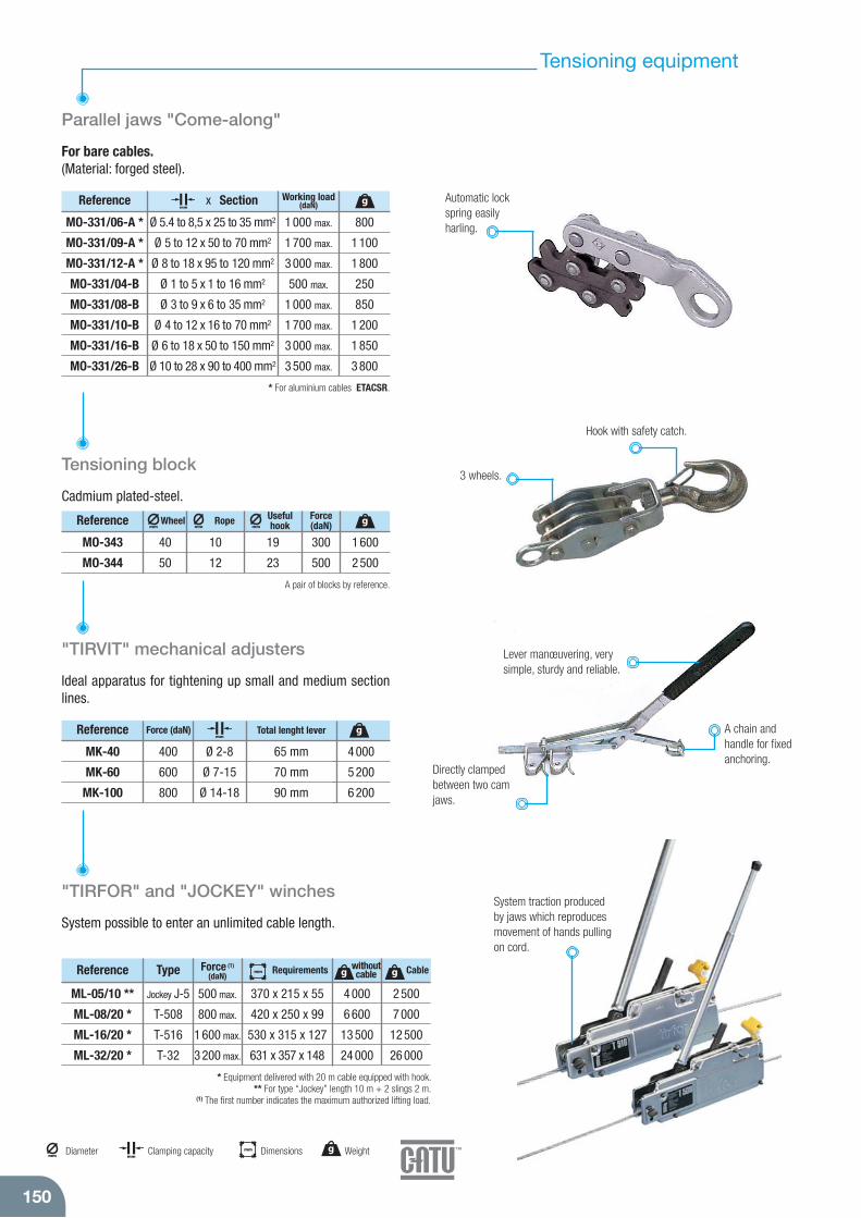
150
Tensioning equipment
Reference
MO-343
MO-344
40
50
19
23
10
12
300
500
1 600
2 500
Parallel jaws "Come-along"
For bare cables. (Material: forged steel).
mm
* Equipment delivered with 20 m cable equipped with hook. ** For type “Jockey” length 10 m + 2 slings 2 m.
(1) The first number indicates the maximum authorized lifting load.
"TIRVIT" mechanical adjusters
Ideal apparatus for tightening up small and medium sectionlines.
Reference
MK-40
MK-60
MK-100
400
600
800
Ø 2-8
Ø 7-15
Ø 14-18
65 mm
70 mm
90 mm
4 000
5 200
6 200
Total lenght lever
MO-331/06-A *
MO-331/09-A *
MO-331/12-A *
MO-331/04-B
MO-331/08-B
MO-331/10-B
MO-331/16-B
MO-331/26-B
Ø 5.4 to 8,5 x 25 to 35 mm2
Ø 5 to 12 x 50 to 70 mm2
Ø 8 to 18 x 95 to 120 mm2
Ø 1 to 5 x 1 to 16 mm2
Ø 3 to 9 x 6 to 35 mm2
Ø 4 to 12 x 16 to 70 mm2
Ø 6 to 18 x 50 to 150 mm2
Ø 10 to 28 x 90 to 400 mm2
1 000 max.
1 700 max.
3 000 max.
500 max.
1 000 max.
1 700 max.
3 000 max.
3 500 max.
Working load(daN)x SectionReference
Tensioning block
Cadmium plated-steel.
mmRope
mm
Usefulhookmm
Reference
ML-05/10 **
ML-08/20 *
ML-16/20 *
ML-32/20 *
Jockey J-5
T-508
T-516
T-32
370 x 215 x 55
420 x 250 x 99
530 x 315 x 127
631 x 357 x 148
500 max.
800 max.
1 600 max.
3 200 max.
4 000
6 600
13 500
24 000
2 500
7 000
12 500
26 000
"TIRFOR" and "JOCKEY" winches
System possible to enter an unlimited cable length.
Type withoutcable CableRequirements
3 wheels.
Hook with safety catch.
mmgDiameter Weight
mmClamping capacity
g
g g
g
Automatic lockspring easilyharling.
mm Dimensions
mm
Lever manœuvering, verysimple, sturdy and reliable.
Directly clampedbetween two camjaws.
A chain andhandle for fixedanchoring.
A pair of blocks by reference.
* For aluminium cables ETACSR.
Wheel
System traction producedby jaws which reproducesmovement of hands pullingon cord.
Force (1)
(daN)mm
800
1 100
1 800
250
850
1 200
1 850
3 800
g
Force(daN)
Force (daN)
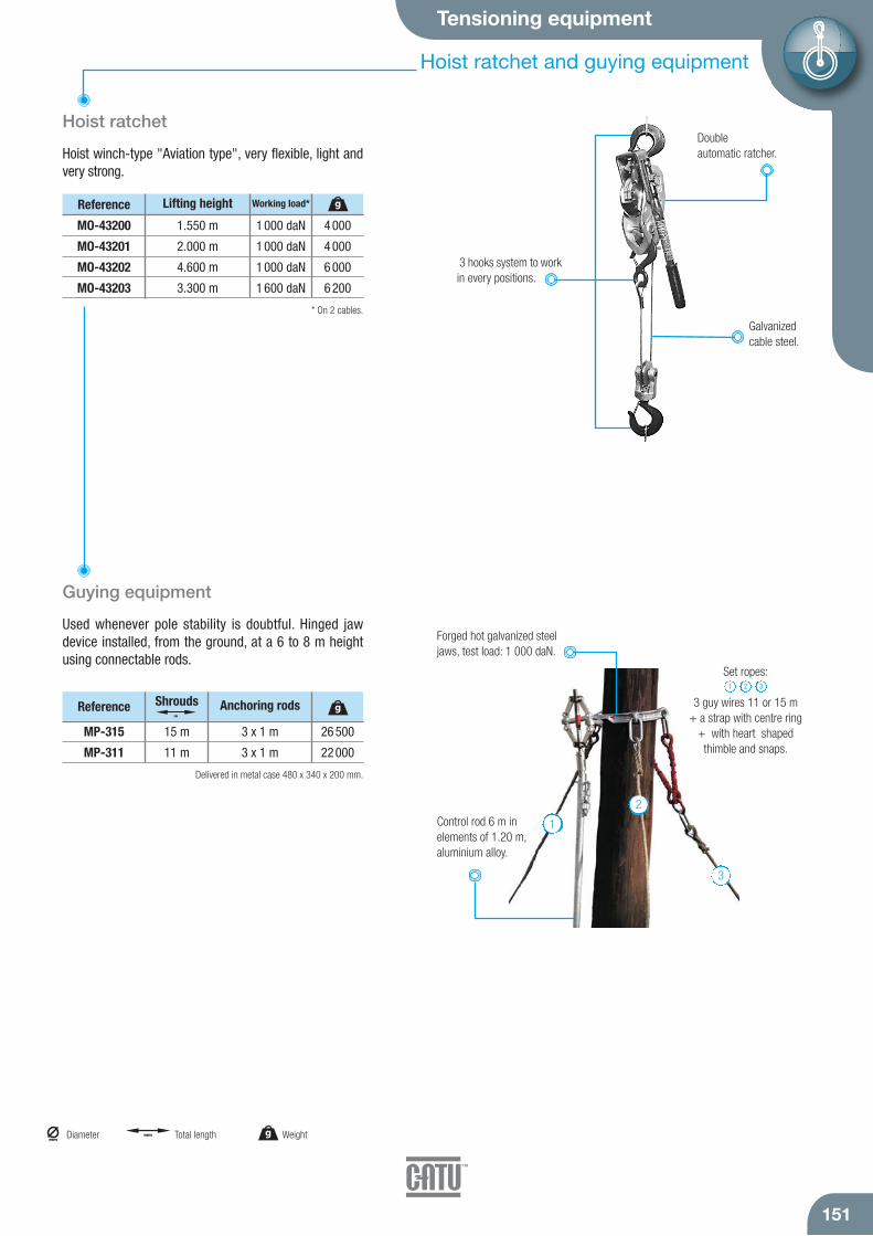
Tensioning equipment
151
Hoist ratchet and guying equipment
Reference
MO-43200
MO-43201
MO-43202
MO-43203
1.550 m
2.000 m
4.600 m
3.300 m
1 000 daN
1 000 daN
1 000 daN
1 600 daN
Lifting height Working load*
Hoist ratchet
Hoist winch-type "Aviation type", very flexible, light andvery strong.
Guying equipment
Used whenever pole stability is doubtful. Hinged jaw device installed, from the ground, at a 6 to 8 m heightusing connectable rods.
Reference
MP-315
MP-311
15 m
11 m
3 x 1 m
3 x 1 m
Set ropes:
3 guy wires 11 or 15 m + a strap with centre ring
+ with heart shaped thimble and snaps.
1 2 3
Double automatic ratcher.
3 hooks system to workin every positions.
Galvanizedcable steel.
* On 2 cables.
Delivered in metal case 480 x 340 x 200 mm.
Control rod 6 m inelements of 1.20 m,aluminium alloy.
Anchoring rods
Forged hot galvanized steeljaws, test load: 1 000 daN.
1
2
3
4 000
4 000
6 000
6 200
g
26 500
22 000
gShroudsm
mmgDiameter Weightmm Total length
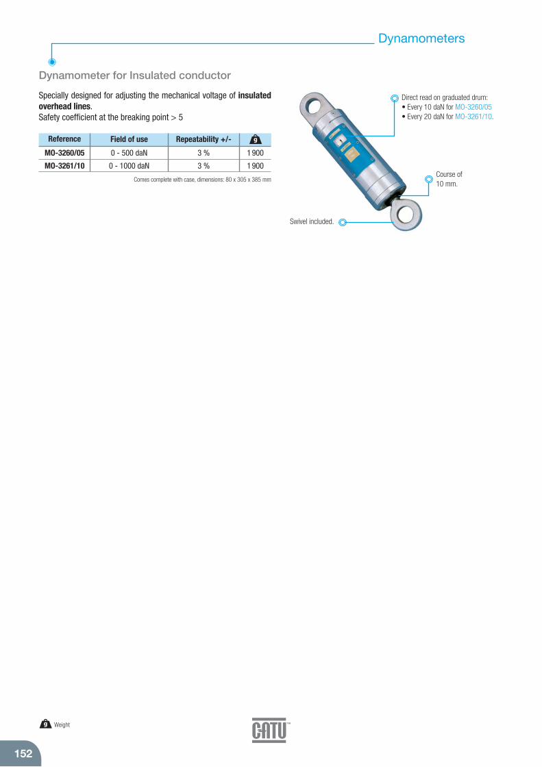
152
Dynamometers
Dynamometer for Insulated conductor
Specially designed for adjusting the mechanical voltage of insulatedoverhead lines.Safety coefficient at the breaking point > 5
Reference
MO-3260/05
MO-3261/10
0 - 500 daN
0 - 1000 daN
3 %
3 %
Repeatability +/-Field of use
g Weight
Direct read on graduated drum:• Every 10 daN for MO-3260/05• Every 20 daN for MO-3261/10.
Swivel included.
Comes complete with case, dimensions: 80 x 305 x 385 mmCourse of10 mm.
1 900
1 900
g

Atex lights 154
Safety shunt and accessories 155
Explosive atmosphere

154
Atex Lights
Intrinsically safe ATEX LED's Headlamp
Agreement ATEXEuropean certificate category 2 (zone 1)N° ITSO9ATEX26185X
II 2 G Ex ia IIB T4.Can be carried either on the head on any kind of helmet.Autonomy: 150 hours.Very light, ABS body.Range: 10 to 15 meters.
Lighting by 3 high performance White LEDs.
Adjustable lamp height angle.
Strap: cloth or siliconerubber (for helmet).
Reference
MS-126 125
g
76 x 68 x 44
mm
Delivered with batteries and 2 Straps.
3 x 1.5 V
type LRO3 (AAA)
MS-129
MS-130
MS-130/1
Reference
50
210
220
g
0.139
0.178
0.178
21
72
40
2 AAA included
4 AA not included
4 AA NiMH included
mm Dimensions g Weight
Bloc NiMHlong life.
Torchs for explosive atmosphere(ATEX)
Mini-pocket yellow torch, Zone 0.For maintenance and control operations.
II 1 G Ex ia IIC T4Ga Ex ia D 20IP 65.Maxi temperature 90°C.4 hours autonomy.
MS-129
Yellow torch, Zone 0 with polycarbonate body.II 1 G Ga Ex ia IIC T4
II 1 D Da Ex ia D 20IP 66.Maxi temperature 83°C.7.25 hours autonomy.
MS-130
Yellow torch Zone 1 rechargeable version of MS-130.Transformer operating on 220 V or 12 V.
II 2 G Ex ib IIC T4.32 hours autonomy.
MS-130/1
m
Strap.
Clip.
Inversed reflexion module “Recoil LED”.
New generation led.
Security screw.
Pen size and body inpolycarbonate.
Lumens

Explosive atmosphere
Safety shunt and accessories
155
mm Dimensions g Weight
Earthing coil
Earthing coil for explosive atmospheres Zones 0, 1, 2.Guarantees bonding loads.
Reference Description
ENR-15-ATEX With 15 m cable 13 000
g
Cable guide roller with self-lubrificated.
EarthingClamp.
ENR-15-ATEX
Earthing box withwarning light.
Link electrical collector anti-spark catch.

156
Golden safety rules
SEPARATE THE WORK AREA FROM ALL POSSIBLESOURCES OF POWER-SUPPLY
by opening circuit-breakers, switches…
LOCK THE LINK IN THE OPEN POSITIONwith a safety lock system (safety padlock)
CHECK THE ABSENCE OF VOLTAGEat source and on site, on each conductor and
apparatus involved.
APPLY APPROPRIATE SHORT-CIRCUIT ANDEARTHING SYSTEMSin sufficient numbers on the conductors of your networkwhere operation is taking place.
SHOWN, WARN OTHERS AND LIMIT THE WORK AREAeven during the most simple temporary
maintenance operation
1
2
3
4
5
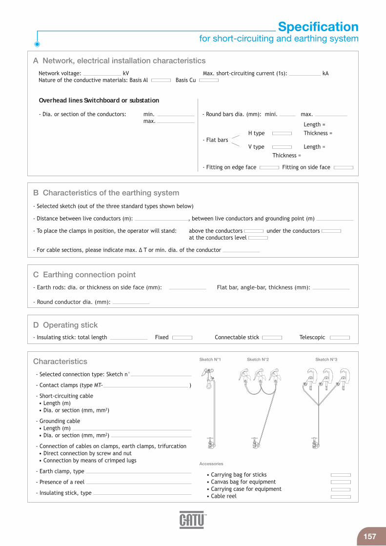
157
Specificationfor short-circuiting and earthing system
- Earth rods: dia. or thickness on side face (mm): Flat bar, angle-bar, thickness (mm):
- Round conductor dia. (mm):
- Insulating stick: total length Fixed Connectable stick Telescopic
- Selected sketch (out of the three standard types shown below)
- Distance between live conductors (m): , between live conductors and grounding point (m)
- To place the clamps in position, the operator will stand: above the conductors under the conductors at the conductors level
- For cable sections, please indicate max. Δ T or min. dia. of the conductor
Network voltage: kV Max. short-circuiting current (1s): kANature of the conductive materials: Basis Al Basis Cu
Overhead lines Switchboard or substation
- Dia. or section of the conductors: min. - Round bars dia. (mm): mini. max. max.
- Selected connection type: Sketch n°
- Contact clamps (type MT- )
- Short-circuiting cable • Length (m) • Dia. or section (mm, mm2)
- Grounding cable • Length (m)
• Dia. or section (mm, mm2)
- Connection of cables on clamps, earth clamps, trifurcation • Direct connection by screw and nut • Connection by means of crimped lugs
- Earth clamp, type
- Presence of a reel
- Insulating stick, type
• Carrying bag for sticks • Canvas bag for equipment • Carrying case for equipment • Cable reel
Characteristics
D Operating stick
C Earthing connection point
B Characteristics of the earthing system
Accessories
Sketch N°1 Sketch N°2 Sketch N°3
Length = H type Thickness = - Flat bars V type Length = Thickness = - Fitting on edge face Fitting on side face
A Network, electrical installation characteristics

Chooseyour gloves size!
6 7 8 9 10 11
Check
Put your hand on the drawing and look yoursize on the right.
158
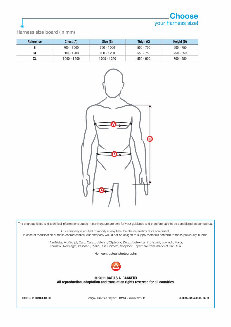
Harness size board (in mm)
Chooseyour harness size!
The characteristics and technical informations stated in our literature are only for your guidance and therefore cannot be considered as contractual.
Our company is entitled to modify at any time the characteristics of its equipment. In case of modification of these characteristics, our company would not be obliged to supply materials conform to those previously in force.
“Alu-Metal, Alu-Script, Catu, Catex, Catohm, Clipblock, Detex, Detex-Lumifix, Isomil, Lowlock, Major, Normafix, Normagrif, Pelican 2, Piezo-Test, Pointest, Snaplock, Triplix” are trade marks of Catu S.A.
Non contractual photographs
PRINTED IN FRANCE BY FOI GENERAL CATALOGUE RG-11
© 2011 CATU S.A. BAGNEUXAll reproduction, adaptation and translation rights reserved for all countries.
Design / direction / layout: COMST - www.comst.fr
A
B
C
D
Chest (A) Size (B)
S
M
XL
700 - 1 000
800 - 1 200
1 000 - 1 500
750 - 1 000
900 - 1 200
1 000 - 1 350
500 - 700
550 - 750
550 - 900
600 - 750
750 - 850
700 - 950
Height (D)Thigh (C)Reference
Distributed by:
www.catuelec.comCATU • 10/20 Avenue JEAN-JAURES • B.P.2 • 92222 BAGNEUX CEDEX (FRANCE) •
• Phone: (33) 01 42 31 46 00 • Fax: (33) 01 42 31 46 32 • Phone business: (33) 01 42 31 46 46 •
SICAME GROUP