Catia Lab Manual
93
ANNA UNIVERSITY OF TECHNOLOGY TIRUNELVELI TIRUNELVELI-627 007 CAD LABORATORY RECORD NOTE BOOK NAME :……………………………………………….. REG NO :……………………………………………….. SEMESTER :……………………………………………….. DEGREE :………………………………………………... SUBJECT :………………………………………………… DEPARTMENT : …………………………………………………
-
Upload
rameez-farouk -
Category
Documents
-
view
1.377 -
download
204
description
This manual consists of drawing and the procedure for drawing it using Catia tool.
Transcript of Catia Lab Manual
ANNA UNIVERSITY OF TECHNOLOGY TIRUNELVELI
TIRUNELVELI-627 007
CAD LABORATORY RECORD NOTE BOOK
NAME :………………………………………………..
REG NO :………………………………………………..
SEMESTER :………………………………………………..
DEGREE :………………………………………………...
SUBJECT :…………………………………………………
DEPARTMENT : …………………………………………………
vijaynandhu
Rectangle
vijaynandhu
Rectangle

Name : Programme : Roll No : Subject : Department : Branch : Semester : REGISTER NO : Certified to the bonafide record of practical work done by
Mr/Ms……………………………………………………………………………
in the …………………………………………..laboratory during the period
……………………………….. 2010 - 2011.
DATE: Signature of faculty-in-charge signature of H O D Submitted for the practical examination held on …………………………...
Internal Examiner External Examiner
BONAFIDE CERTIFICATE
ANNA UNIVERSITY OF TECHNOLOGY TIRUNELVELI
TIRUNELVELI - 627 007

S.NO DATE EX.NO DESCRPTION PAGE NO SIGNATURE
1 Introduction 1
2 EX.NO.01 Isometric view-1 12
3 EX.NO.02 Isometric view-2 16
4 EX.NO.03 Isometric view-3 20
5 EX.NO.04 Isometric view-4 24
6 EX.NO.05 Isometric view-5 28
7 EX.NO.06 Isometric view-6 32
8 EX.NO.07 Isometric view-7 36
9 EX.NO.08 Isometric view-8 40
10 EX.NO.09 Isometric view-9 44
11 EX.NO.10 Isometric view-10 48
12 EX.NO.11 Assembly Of Sleeve and Cotter joint 52
13 EX.NO.12 Assembly Of Gib and Cotter joint 56
14 EX.NO.13 Assembly Of Knuckle joint 60
15 EX.NO.14 Assembly Of Flanged Coupling 64
16 EX.NO.15 Assembly Of Universal Coupling 68
17 EX.NO.16 Assembly Of Plummer Block 72
18 EX.NO.17 Assembly Of Simple Ecentric 76
19 EX.NO.18 Assembly Of Screw Jack 80
20 EX.NO.19 Assembly Of Stuffing Box 84
21 EX.NO.20 Assembly Of Bushed Bearing 88
INDEX

INTRODUCTION
In cad laboratory we are going to study about how to create a model of engineering
objects and also how to create an assembly of modeled objects. The modeling softwares like
catia, pro e, unigraphics are generally used in mechanical engineering field for the modeling. In
this lab catia-v5r18 software is used to do the exercises.
CATIA (Computer Aided Three-dimensional Interactive Application) is a multi-platform
CAD/CAM/CAE. It is written in the C++ programming language. Commonly referred to as a 3D
Product Lifecycle Management software suite, CATIA supports multiple stages of product
development (CAx), from conceptualization, design (CAD), manufacturing (CAM), and
engineering (CAE).CATIA can be customized via application programming interfaces (API). V4
can be adapted in the Fortran and C Programming languages under an API called CAA
(Component Application Architecture). V5 can be adapted via the Visual Basic and C++
programming languages, an API called CAA2 or CAA V5 that is a component object model
(COM)-like interface. Although later versions of CATIA V4 implemented NURBS, V4
principally used piecewise polynomial surfaces.
1.1 AN OVERVIEW OF CATIA DESIGN SOFTWARE
1.1.1 Optimal Sharing.
Catia V6 users will get access to a unique, collaborative 3 dimensional environment that
can be access by an unlimited number of people online. This allows people from across the globe
to collaborate in a virtual environment. It has been designed to not only allow for online
cooperation, but also makes offline sharing and designing easy to integrate as well.
1.1.2. Simplified Product Development.
Creating a new product can be a long and complex process. It encompasses multiple
design phases including the initial design, overall development, and manufacturing. Catia V6
decreases the complexity and length of the entire project because it integrates various stages of
the development process so that they can be controlled and modified on a single platform. It does
this by using an approach to systems engineering known as RFLP. This allows you to create
several versions of the same product using different sets of requirements. This gives you a
comprehensive look at what the final product could be.
1
1.1.3. Seamless Transitioning.
Every version of the Catia design software is designed to allow for seamless integration
with previous versions. This makes upgrading a simple process and can be completed without
losing any of the information that has already been stored.
Catia design software has found its way into more and more industries with each passing year.
Traditionally, it gained notoriety through 3 main industries; however every industry that is
involved in engineering has found it useful.
Catia has become a leader in product development software and may be exactly what is needed
to overcome the shortcomings of CAD software.
1.2 Tool Bars
Many standard toolbars are used in the different modes like sketcher mode operational
mode etc, In catia software. Here we discuss about the tool bars used in sketcher with some
examples.
1.2.1 Sketcher Work Bench Tool Bars
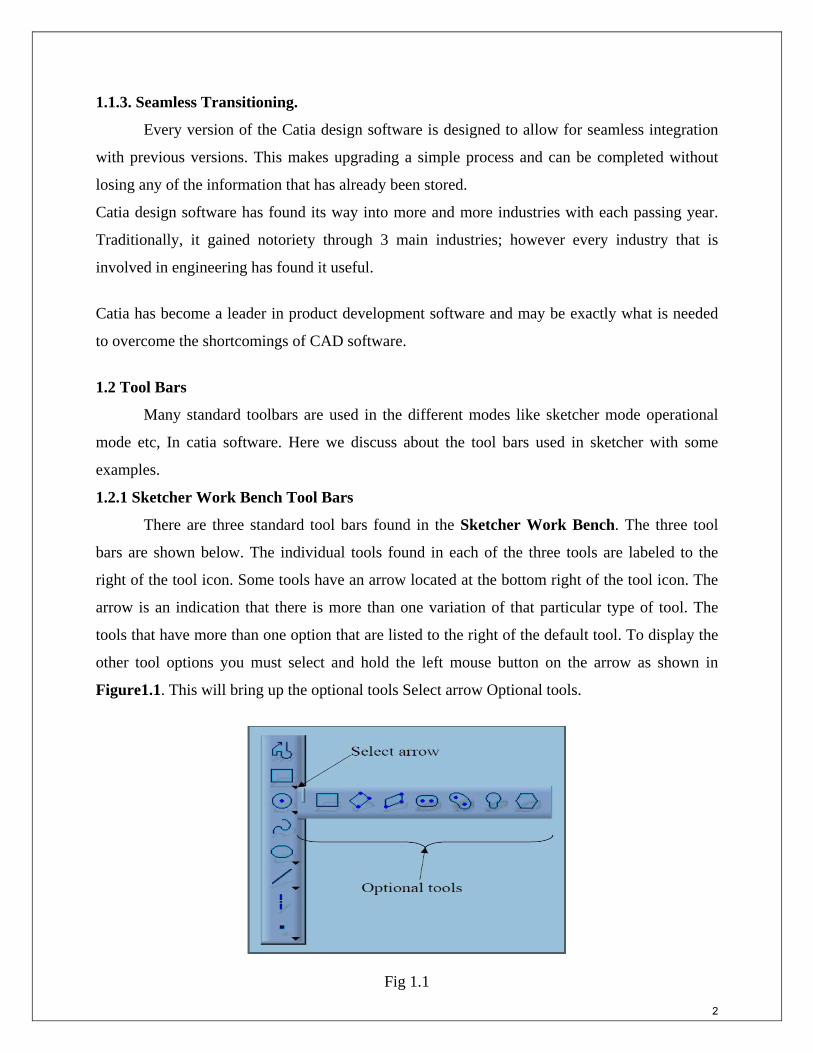
There are three standard tool bars found in the Sketcher Work Bench. The three tool
bars are shown below. The individual tools found in each of the three tools are labeled to the
right of the tool icon. Some tools have an arrow located at the bottom right of the tool icon. The
arrow is an indication that there is more than one variation of that particular type of tool. The
tools that have more than one option that are listed to the right of the default tool. To display the
other tool options you must select and hold the left mouse button on the arrow as shown in
Figure1.1. This will bring up the optional tools Select arrow Optional tools.
Fig 1.1 2

THE OPERATION TOOL BAR THE PROFILE TOOL BAR
Fig 1.2
THE CONSTRAINTS TOOL BAR
Fig 1.3
3

Fig 1.4
1.3 Specify A Working Plane The next step is to create a 2 dimensional profile of the part. The Sketcher Work
Bench is a two dimensional (planar) work area. To use the Sketcher Work Bench, you must
specify which plane the profile is to be created on. Specifying, the plane can be done several
different ways.
ZX plane
Fig 1.5
4
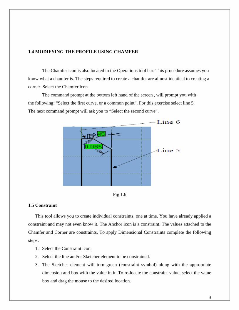
1.4 MODIFYING THE PROFILE USING CHAMFER
The Chamfer icon is also located in the Operations tool bar. This procedure assumes you
know what a chamfer is. The steps required to create a chamfer are almost identical to creating a
corner. Select the Chamfer icon.
The command prompt at the bottom left hand of the screen , will prompt you with
the following: “Select the first curve, or a common point”. For this exercise select line 5.
The next command prompt will ask you to “Select the second curve”.
Fig 1.6
1.5 Constraint
This tool allows you to create individual constraints, one at time. You have already applied a
constraint and may not even know it. The Anchor icon is a constraint. The values attached to the
Chamfer and Corner are constraints. To apply Dimensional Constraints complete the following
steps:
1. Select the Constraint icon.
2. Select the line and/or Sketcher element to be constrained.
3. The Sketcher element will turn green (constraint symbol) along with the appropriate
dimension and box with the value in it .To re-locate the constraint value, select the value
box and drag the mouse to the desired location.
5

4. If the initial location of the constraint is not satisfactory re-select the dimension and drag
and drop it at the new location.
5. To edit the value of the constraint double click on the value box. This will bring up the
Constraint Definition pop up window shown in. This window shows the existing value
forthe Sketcher element. This value can be edited by typing the newvalue over the
existing value. Then select OK or hit the Enter key. The entities linked to the constraint
will automatically be updated to the new value.
6. If the constraint is between two different entities, such as lines, select the first line and
then the second line.CATIA V5 will constrain the distance between the two entities. The
constraint value will appear near the constraint. To move the constraint value. For this
lesson constrain your “L Shaped Extrusion” similar to the one shown in Figure
Fig 1.7
1.6 Practice Exercises:
Now that your CATIA V5 tool box has some tools in it, put them to use on the following
practice exercises. The shapes are simple and can be completed in one sketch. The dimensions
represent the constraints you are to use in the Sketcher Work Bench. The first practice exercise
has the suggested steps to completing the task along with some helpful hints. 6

Each subsequent practice exercise contains less suggested steps and helpful hints. By the
last practice exercise you will be on your own.
Using the Sketcher Work Bench and create the following profile and extrude to the
dimensions shown below. When completed save as CAT Part”.
Fig 1.8
Suggested Steps:
1. Select the XY plane (the plane the profile will be sketched on).Reference Step 3 for
information on selecting planes.
2. Enter the Sketcher Work Bench. Reference Step 4.
3. Sketch the profile of the part. Hint: use the Profile tool.
4. Anchor the lower left hand corner of the sketch. For anchoring a profile.
5. Constrain the profile to match the dimensions shown above. Reference Step 18 for
constraining a profile.
6. Exit the Sketcher Work Bench, return to the Part Design Work Bench (the 3D
environment). Reference Step 21 for exciting the Sketcher Work Bench and entering the Part
Design Work Bench.
7. Once in the Part Design Work Bench extrude the profile to the dimension shown (2”).
Reference Step 22 for extruding a profile.
8. Save the part as told in “Reference Step23for saving a file.
7

This part (profile) should be straightforward. This would be a good exerciseto try
different methods of constraining and testing the results. Save the shape as mensioned.
Exercise 2.CAT Part”.
Fig 1.9
To help make it easier to sketch this part set the grid Primary Spacing to 1and the Graduations
to 4. This will put the grid lines in the Sketcher screen to a .25 inch spacing. With that spacing
all you have to do is snap to the intersections of the grid to sketch the part.
This practice exercise is a little bit more challenging, lets see what you can down with it. Save
this CAT Part as Exercise 3.CATPart”.
Fig 1.10
8

It is not as complicated as it looks. If your grid Graduations is set to 10 just snap to the
intersections for the beginning and ending points of your lines. To set the constraint for the
angles select the angled lines and the angle constraint will appear. Reference Step 19 for
modifying the angle value. If the profile gets over constrained delete the Parallel constraint.
Save the file as “ Exercise 3.CATPart”.
This practice exercise should challenge you. For this part use radius values, not angles.
Save this CAT Part as “Exercise 4.CATPart”.
Fig 1.11
This part can be done using the radius option in the profile command. Before starting, set the
grid Primary Spacing to 1 and the Graduations to 4.
SKETCHING WITH THE PROFILE ICON (RADIUS OPTION)
1. Starting at the bottom left corner of the part.
2. Select the Profile icon from the right menu bar.
3. Sketch the vertical 1.50 inch line that defines the left edge of the part.
9

4. Now sketch the first arc along the top of the part. To do this hold down the left mouse
button and drag it in the direction you want the arc to go then release the mouse button.
The arc will appear and allow you to drag and place it where you want. Place it on the
grid intersection 2 inches above the bottom of the part and a half-inch to the right. This
will only create half of the arc needed, so the process will have to be repeated to sketch
the other half of the arc.
5. Finish sketching the rest of the part. When you reach the inside .25 radius,
6. When the sketch is done constrain it to double check that all the dimensions match the
part shown above. Make the necessary changes if needed.
This will give you more practice using the line and corner icons. Save this CAT Part as
Exercise 5.CAT Part”
Fig 1.12 Use the Line or Profile icon first to sketch the profile using sharp corners (no radius).
Once it is constrained to the dimensions above, go back and add in the radiuses using the Corner
icon.
*******
10

11
vijaynandhu
Typewritten Text
vijaynandhu
Typewritten Text
vijaynandhu
Typewritten Text
vijaynandhu
Typewritten Text
vijaynandhu
Typewritten Text
vijaynandhu
Typewritten Text
vijaynandhu
Typewritten Text
vijaynandhu
Typewritten Text
vijaynandhu
Typewritten Text
vijaynandhu
Typewritten Text
NAME : REG.NO : CLASS : M.E CAD I YEAR
vijaynandhu
Typewritten Text
vijaynandhu
Typewritten Text
vijaynandhu
Typewritten Text
vijaynandhu
Typewritten Text
vijaynandhu
Typewritten Text
vijaynandhu
Rectangle
vijaynandhu
Rectangle

EX.NO 1 ISOMETRIC VIEW - 1
DATE:
AIM:
Preparation of 3D model using CATIA V5.18 software
TOOLS USED:
Pad, Pocketing etc.,
PROCEDURE:
1. Click the Sketcher icon to start the Sketcher workbench.
2. Select XY, YZ, ZX plane to define the sketch plane, now the Sketcher workbench is
displayed, it contains the tools needed for sketching any profile.
3. Select the profile and draw the part which is given in the model.
4. Using Constraint command the dimensions are modified as per the given model.
5. Exit the Sketcher workbench, click Pad and give the thickness for the part.
6. Select the face to define the work plane and draw the second element.
7. Using Pocket command material is removed and the final model is created.
12
vijaynandhu
Rectangle

13
vijaynandhu
Typewritten Text
NAME : REG.NO : CLASS : M.E CAD I YEAR
vijaynandhu
Rectangle
vijaynandhu
Rectangle

RESULT:
Thus t he given 3D model as pe r t he dr awing is modelled us ing CATIA V5.18
software.
14
vijaynandhu
Rectangle

15
vijaynandhu
Typewritten Text
NAME : REG.NO : CLASS : M.E CAD I YEAR
vijaynandhu
Rectangle
vijaynandhu
Rectangle

EX.NO 2 ISOMETRIC VIEW - 2
DATE:
AIM:
Preparation of 3D model using CATIA V5.18 software
TOOLS USED:
Pad, Pocketing
PROCEDURE:
1. Click the Sketcher icon to start the Sketcher workbench.
2. Select XY, YZ, ZX plane to define the sketch plane, now the Sketcher workbench is
displayed, it contains the tools needed for sketching any profile.
3. Select the profile and draw the part which is given in the model.
4. Using Constraint command the dimensions are modified as per the given model.
5. Exit the Sketcher workbench, click Pad and give the thickness for the part.
6. Select the face to define the work plane and draw the second element.
7. Using Pocket command material is removed and the final model is created.
16
vijaynandhu
Rectangle

17
vijaynandhu
Typewritten Text
NAME : REG.NO : CLASS : M.E CAD I YEAR
vijaynandhu
Rectangle
vijaynandhu
Rectangle

RESULT:
Thus the given 3D model as per the drawing is modelled using CATIA V5.18 software.
18
vijaynandhu
Rectangle

19
vijaynandhu
Typewritten Text
NAME : REG.NO : CLASS : M.E CAD I YEAR
vijaynandhu
Rectangle
vijaynandhu
Rectangle

EX.NO 3 ISOMETRIC VIEW - 3
DATE:
AIM:
Preparation of 3D model using CATIA V5.18 software
TOOLS USED:
Pad, Pocketing
PROCEDURE:
1. Click the Sketcher icon to start the Sketcher workbench.
2. Select XY, YZ, ZX plane to define the sketch plane, now the Sketcher workbench is
displayed, it contains the tools needed for sketching any profile.
3. Select the profile and draw the part which is given in the model.
4. Using Constraint command the dimensions are modified as per the given model.
5. Exit the Sketcher workbench, click Pad and give the thickness for the part.
6. Select the face to define the work plane and draw the second element.
7. Using Pocket command material is removed and the final model is created.
20
vijaynandhu
Rectangle

21
vijaynandhu
Typewritten Text
NAME : REG.NO : CLASS : M.E CAD I YEAR
vijaynandhu
Rectangle
vijaynandhu
Rectangle

RESULT:
Thus the given 3D model as per the drawing is modelled using CATIA V5.18 software.
22
vijaynandhu
Rectangle
23
vijaynandhu
Typewritten Text
NAME : REG.NO : CLASS : M.E CAD I YEAR
vijaynandhu
Rectangle
vijaynandhu
Rectangle

EX.NO 4 ISOMETRIC VIEW -4
DATE:
AIM:
Preparation of 3D model using CATIA V5.18 software
TOOLS USED:
Pad, Pocketing
PROCEDURE:
1. Click the Sketcher icon to start the Sketcher workbench.
2. Select XY, YZ, ZX plane to define the sketch plane, now the Sketcher workbench is
displayed, it contains the tools needed for sketching any profile.
3. Select the profile and draw the part which is given in the model.
4. Using Constraint command the dimensions are modified as per the given model.
5. Exit the Sketcher workbench, click Pad and give the thickness for the part.
6. Select the face to define the work plane and draw the second element.
7. Using Pocket command material is removed and the final model is created.
24
vijaynandhu
Rectangle

25
vijaynandhu
Typewritten Text
NAME : REG.NO : CLASS : M.E CAD I YEAR
vijaynandhu
Rectangle
vijaynandhu
Rectangle

RESULT:
Thus the given 3D model as per the drawing is modelled using CATIA V5.18 software.
26
vijaynandhu
Rectangle

27
vijaynandhu
Typewritten Text
NAME : REG.NO : CLASS : M.E CAD I YEAR
vijaynandhu
Rectangle
vijaynandhu
Rectangle

EX.NO 5 ISOMETRIC VIEW - 5
DATE:
AIM:
Preparation of 3D model using CATIA V5.18 software
TOOLS USED:
Pad, Pocketing
PROCEDURE:
1. Click the Sketcher icon to start the Sketcher workbench.
2. Select XY, YZ, ZX plane to define the sketch plane, now the Sketcher workbench is
displayed, it contains the tools needed for sketching any profile.
3. Select the profile and draw the part which is given in the model.
4. Using Constraint command the dimensions are modified as per the given model.
5. Exit the Sketcher workbench, click Pad and give the thickness for the part.
6. Select the face to define the work plane and draw the second element.
7. Using Pocket command material is removed and the final model is created.
28
vijaynandhu
Rectangle

29
vijaynandhu
Typewritten Text
NAME : REG.NO : CLASS : M.E CAD I YEAR
vijaynandhu
Rectangle
vijaynandhu
Rectangle

RESULT:
Thus the given 3D model as per the drawing is modelled using CATIA V5.18 software.
30
vijaynandhu
Rectangle

31
vijaynandhu
Typewritten Text
NAME : REG.NO : CLASS : M.E CAD I YEAR
vijaynandhu
Rectangle
vijaynandhu
Rectangle

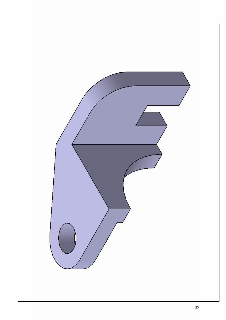
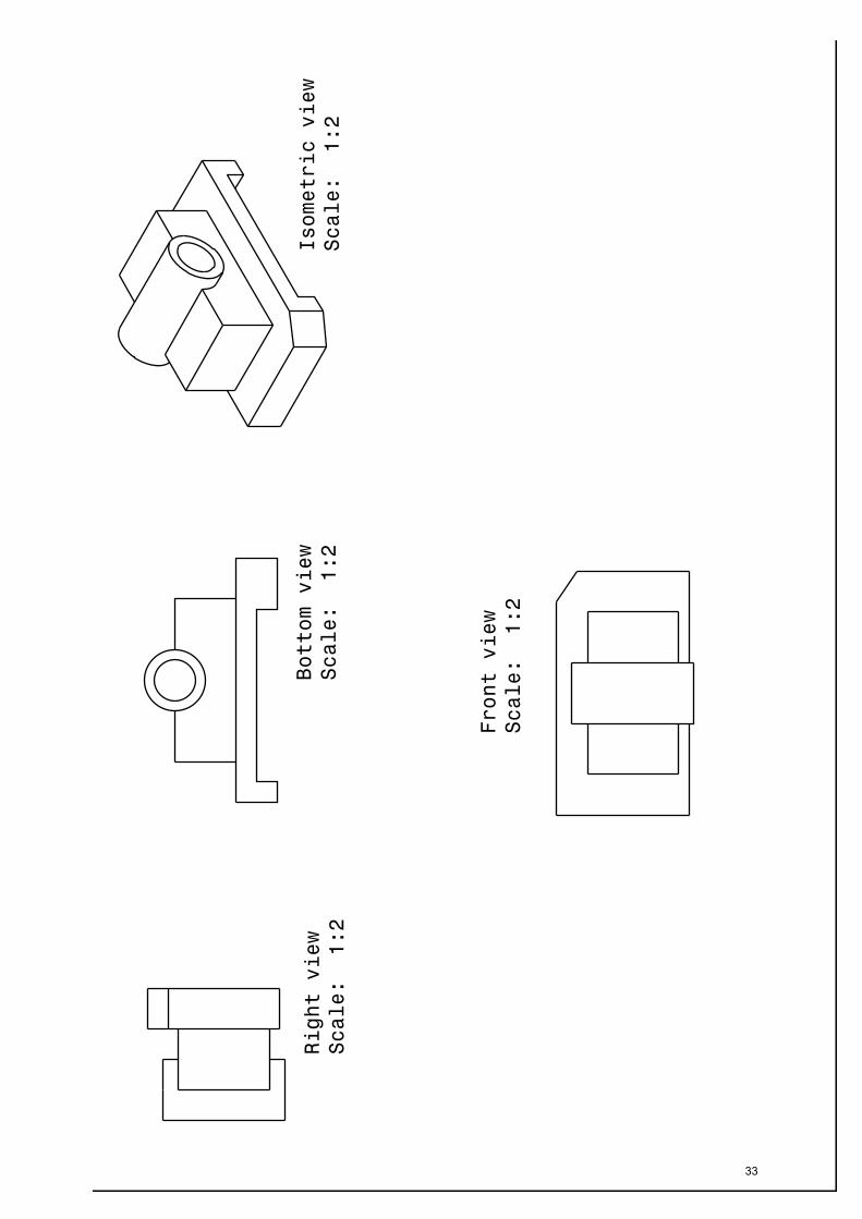
EX.NO 6 ISOMETRIC VIEW - 6
DATE:
AIM:
Preparation of 3D model using CATIA V5.18 software
TOOLS USED:
Pad, Pocketing, chamber
PROCEDURE:
1. Click the Sketcher icon to start the Sketcher workbench.
2. Select XY, YZ, ZX plane to define the sketch plane, now the Sketcher workbench is
displayed, it contains the tools needed for sketching any profile.
3. Select the profile and draw the part which is given in the model.
4. Using Constraint command the dimensions are modified as per the given model.
5. Exit the Sketcher workbench, click Pad and give the thickness for the part.
6. Select the face to define the work plane and draw the second element.
7. Using Pocket command material is removed
8. Select the define edges to be chamfered and the final model is created.
32
vijaynandhu
Rectangle
33
vijaynandhu
Typewritten Text
NAME : REG.NO : CLASS : M.E CAD I YEAR
vijaynandhu
Rectangle
vijaynandhu
Rectangle

RESULT:
Thus the given 3D model as per the drawing is modelled using CATIA V5.18 software.
34
vijaynandhu
Rectangle

35
vijaynandhu
Typewritten Text
NAME : REG.NO : CLASS : M.E CAD I YEAR
vijaynandhu
Rectangle
vijaynandhu
Rectangle

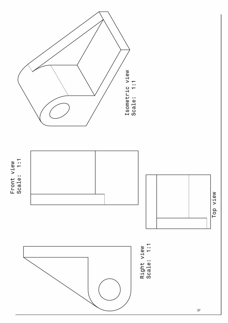
EX.NO 7 ISOMETRIC VIEW - 7
DATE:
AIM:
Preparation of 3D model using CATIA V5.18 software
TOOLS USED:
Pad, Pocketing
PROCEDURE:
1. Click the Sketcher icon to start the Sketcher workbench.
2. Select XY, YZ, ZX plane to define the sketch plane, now the Sketcher workbench is
displayed, it contains the tools needed for sketching any profile.
3. Select the profile and draw the part which is given in the model.
4. Using Constraint command the dimensions are modified as per the given model.
5. Exit the Sketcher workbench, click Pad and give the thickness for the part.
6. Select the face to define the work plane and draw the second element.
7. Using Pocket command material is removed and the final model is created.
36
vijaynandhu
Rectangle
37
vijaynandhu
Typewritten Text
NAME : REG.NO : CLASS : M.E CAD I YEAR
vijaynandhu
Rectangle
vijaynandhu
Rectangle
RESULT:
Thus the given 3D model as per the drawing is modelled using CATIA V5.18 software.
38
vijaynandhu
Rectangle

39
vijaynandhu
Typewritten Text
NAME : REG.NO : CLASS : M.E CAD I YEAR
vijaynandhu
Rectangle
vijaynandhu
Rectangle

EX.NO 8 ISOMETRIC VIEW - 8
DATE:
AIM:
Preparation of 3D model using CATIA V5.18 software
TOOLS USED:
Pad, Pocketing
PROCEDURE:
1. Click the Sketcher icon to start the Sketcher workbench.
2. Select XY, YZ, ZX plane to define the sketch plane, now the Sketcher workbench is
displayed, it contains the tools needed for sketching any profile.
3. Select the profile and draw the part which is given in the model.
4. Using Constraint command the dimensions are modified as per the given model.
5. Exit the Sketcher workbench, click Pad and give the thickness for the part.
6. Select the face to define the work plane and draw the second element.
7. Using Pocket command material is removed and the final model is created.
40
vijaynandhu
Rectangle

41
vijaynandhu
Typewritten Text
NAME : REG.NO : CLASS : M.E CAD I YEAR
vijaynandhu
Rectangle
vijaynandhu
Rectangle

RESULT:
Thus the given 3D model as per the drawing is modelled using CATIA V5.18 software.
42
vijaynandhu
Rectangle

43
vijaynandhu
Typewritten Text
NAME : REG.NO : CLASS : M.E CAD I YEAR
vijaynandhu
Rectangle
vijaynandhu
Rectangle

EX.NO 9 ISOMETRIC VIEW - 9
DATE:
AIM:
Preparation of 3D model using CATIA V5.18 software
TOOLS USED:
Pad, Pocketing
PROCEDURE:
1. Click the Sketcher icon to start the Sketcher workbench.
2. Select XY, YZ, ZX plane to define the sketch plane, now the Sketcher workbench is
displayed, it contains the tools needed for sketching any profile.
3. Select the profile and draw the part which is given in the model.
4. Using Constraint command the dimensions are modified as per the given model.
5. Exit the Sketcher workbench, click Pad and give the thickness for the part.
6. Select the face to define the work plane and draw the second element.
7. Using Pocket command material is removed and the final model is created.
44
vijaynandhu
Rectangle

45
vijaynandhu
Typewritten Text
NAME : REG.NO : CLASS : M.E CAD I YEAR
vijaynandhu
Rectangle
vijaynandhu
Rectangle

RESULT:
Thus the given 3D model as per the drawing is modelled using CATIA V5.18 software.
46
vijaynandhu
Rectangle

47
vijaynandhu
Typewritten Text
NAME : REG.NO : CLASS : M.E CAD I YEAR
vijaynandhu
Rectangle
vijaynandhu
Rectangle

EX.NO 10 ISOMETRIC VIEW -10
DATE:
AIM:
Preparation of 3D model using CATIA V5.18 software
TOOLS USED:
Pad, Pocketing
PROCEDURE:
1. Click the Sketcher icon to start the Sketcher workbench.
2. Select XY, YZ, ZX plane to define the sketch plane, now the Sketcher workbench is
displayed, it contains the tools needed for sketching any profile.
3. Select the profile and draw the part which is given in the model.
4. Using Constraint command the dimensions are modified as per the given model.
5. Exit the Sketcher workbench, click Pad and give the thickness for the part.
6. Select the face to define the work plane and draw the second element.
7. Using Pocket command material is removed and the final model is created.
48
vijaynandhu
Rectangle

49
vijaynandhu
Typewritten Text
NAME : REG.NO : CLASS : M.E CAD I YEAR
vijaynandhu
Rectangle
vijaynandhu
Rectangle

RESULT:
Thus the given 3D model as per the drawing is modelled using CATIA V5.18 software.
50
vijaynandhu
Rectangle
51
vijaynandhu
Sticky Note
Marked set by vijaynandhu
vijaynandhu
Rectangle
vijaynandhu
Typewritten Text
vijaynandhu
Typewritten Text
vijaynandhu
Typewritten Text
vijaynandhu
Typewritten Text
NAME : REG.NO : CLASS : M.E CAD I YEAR
vijaynandhu
Typewritten Text
vijaynandhu
Typewritten Text
vijaynandhu
Typewritten Text
vijaynandhu
Rectangle

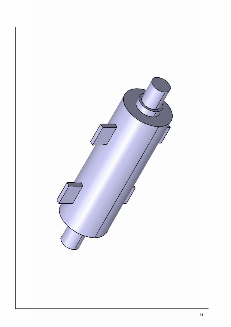
EX.NO 11 ASSEMBLY OF SLEEVE AND COTTER JOINT
DATE:
AIM:
Preparation of 3D Assembly model using CATIA V5.18 software
TOOLS USED:
Existing Component icon, Smart move, Constraining etc.,
PROCEDURE:
1. Assembly Design command is activated to launch the required workbench.
2. The commands for assembling parts are available in the toolbar on the right side of the
application window.
3. Click the Existing Component icon in the Product Structure toolbar, then the File
Selection dialog box is displayed were the required part model is selected.
4. To constrain a model for positioning parts correctly is carried using the various
constraints tools like Constraining and Manipulating and Select the fix component icon,
to Fix a part in the space.
5. Then the parts are assembled in the following order Sleeve, Rod, Cotter by adopting
above methods
6. Select t he u pdate icon for assem bly to be upd ated, all ass embly de sign models ar e
ensured that it is in constraints condition before the models are finished.
52
vijaynandhu
Rectangle

53
vijaynandhu
Typewritten Text
NAME : REG.NO : CLASS : M.E CAD I YEAR
vijaynandhu
Rectangle
vijaynandhu
Rectangle

RESULT:
Thus the given 3D assembly model as per the drawing is modelled using CATIA V5.18 software.
54
vijaynandhu
Rectangle
55
vijaynandhu
Typewritten Text
NAME : REG.NO : CLASS : M.E CAD I YEAR
vijaynandhu
Rectangle
vijaynandhu
Rectangle

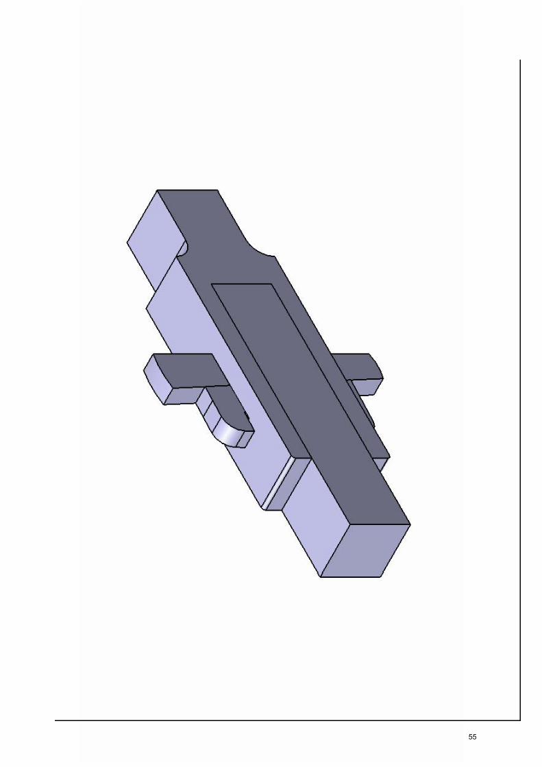
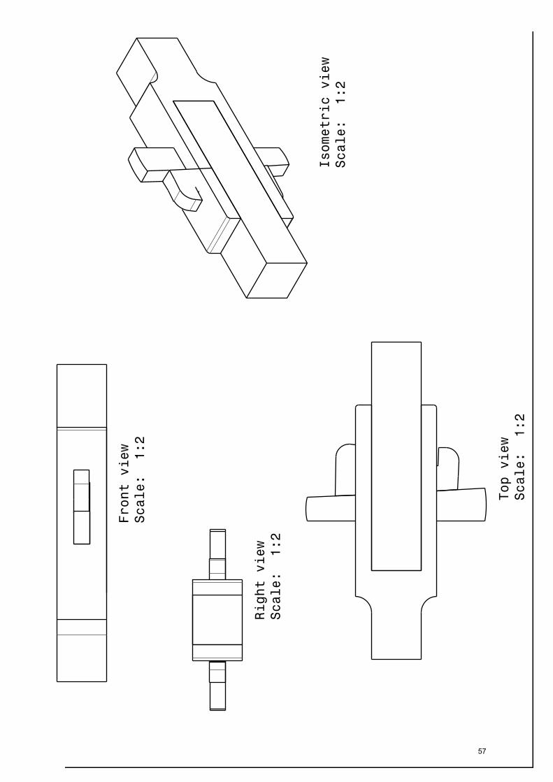
EX.NO 12 ASSEMBLY OF GIB AND COTTER JOINT
DATE:
AIM:
Preparation of 3D Assembly model using CATIA V5.18 software
TOOLS USED:
Existing Component icon, Smart move, Constraining etc.,
PROCEDURE:
1. Assembly Design command is activated to launch the required workbench.
2. The commands for assembling parts are available in the toolbar on the right side of the
application window.
3. Click the Existing Component icon in the Product Structure toolbar, then the File
Selection dialog box is displayed were required the part model is selected.
4. To constrain a model for positioning parts correctly is carried using the various
constraints tools like Constraining and Manipulating and Select the fix component icon,
to Fix a part in the space.
5. Then the parts are assembled in the following order Fork, Block, Gib, Cotter by
adopting above methods
6. Select t he u pdate icon for a ssembly t o b e upd ated, all a ssembly de sign m odels a re
ensured that it is in constraints condition before the models are finished.
56
vijaynandhu
Rectangle
57
vijaynandhu
Typewritten Text
NAME : REG.NO : CLASS : M.E CAD I YEAR
vijaynandhu
Rectangle
vijaynandhu
Rectangle

RESULT:
Thus the given 3D assembly model as per the drawing is modelled using CATIA V5.18 software.
58
vijaynandhu
Rectangle
59
vijaynandhu
Typewritten Text
NAME : REG.NO : CLASS : M.E CAD I YEAR
vijaynandhu
Rectangle
vijaynandhu
Rectangle

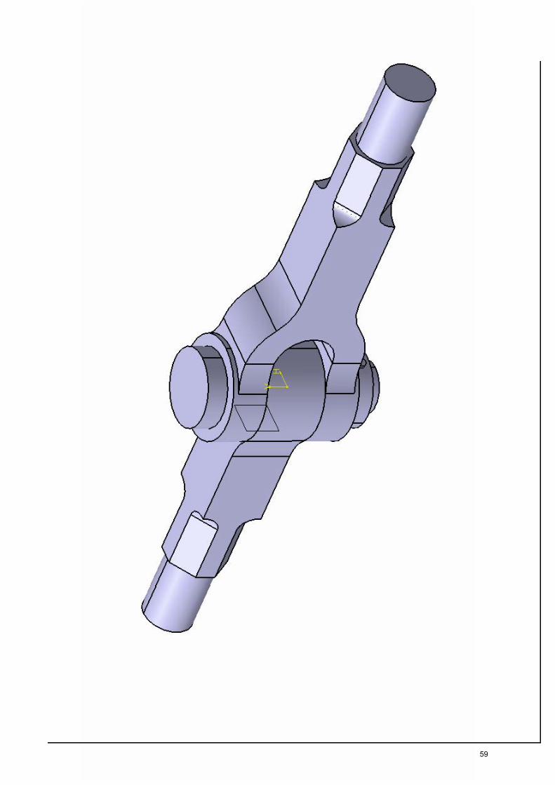
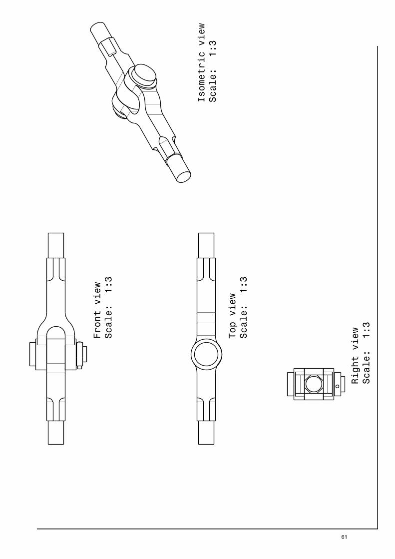
EX.NO 13 ASSEMBLY OF KNUCKLE JOINT
DATE:
AIM:
Preparation of 3D Assembly model using CATIA V5.18 software
TOOLS USED:
Existing Component icon, Smart move, Constraining etc.,
PROCEDURE:
1. Assembly Design command is activated to launch the required workbench.
2. The commands for assembling parts are available in the toolbar on the right side of the
application window.
3. Click the Existing Component icon in the Product Structure toolbar, then the File
Selection dialog box is displayed were required the part model is selected.
4. To constrain a model for positioning parts correctly is carried using the various
constraints tools like Constraining and Manipulating and Select the fix component icon,
to Fix a part in the space.
5. Then t he pa rts a re a ssembled i n t he f ollowing or der Fork end, Eye end. Pin, Collar,
Taper pin by adopting above methods
6. Select t he u pdate icon for assem bly to be upd ated, all ass embly de sign models ar e
ensured that it is in constraints condition before the models are finished.
60
vijaynandhu
Rectangle
61
vijaynandhu
Typewritten Text
NAME : REG.NO : CLASS : M.E CAD I YEAR
vijaynandhu
Rectangle
vijaynandhu
Rectangle

RESULT:
Thus the given 3D assembly model as per the drawing is modelled using CATIA V5.18 software.
62
vijaynandhu
Rectangle
63
vijaynandhu
Typewritten Text
NAME : REG.NO : CLASS : M.E CAD I YEAR
vijaynandhu
Rectangle
vijaynandhu
Rectangle

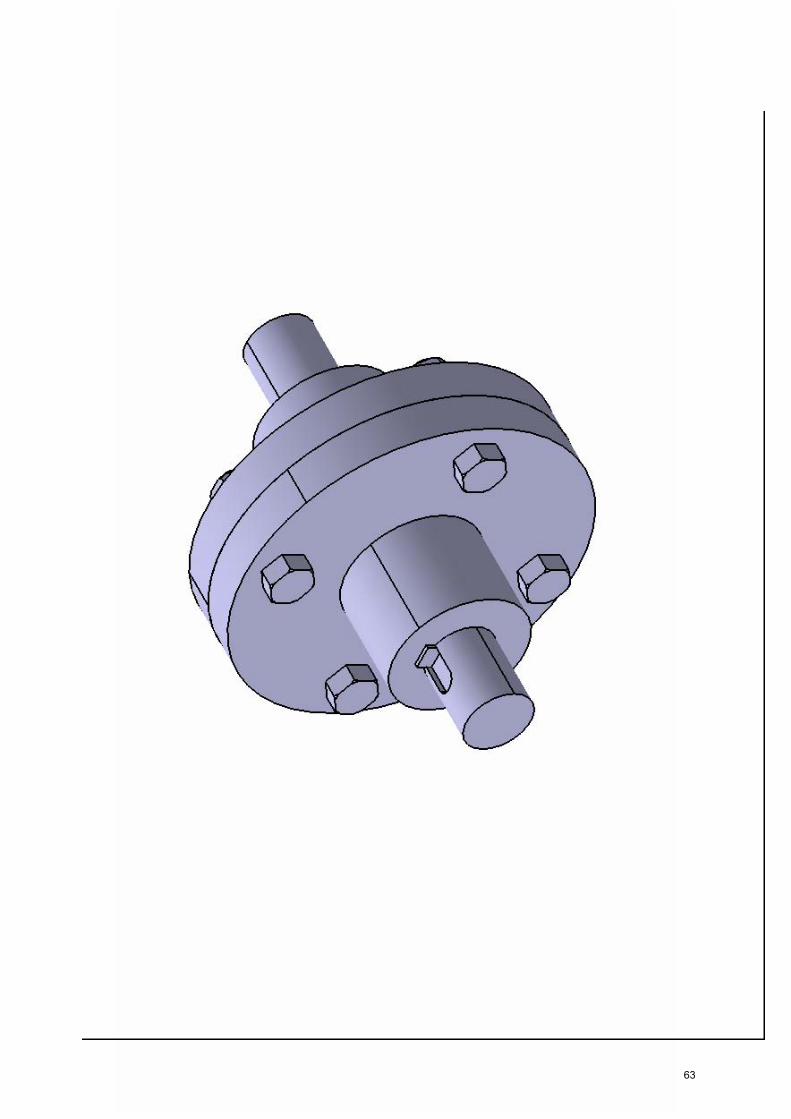
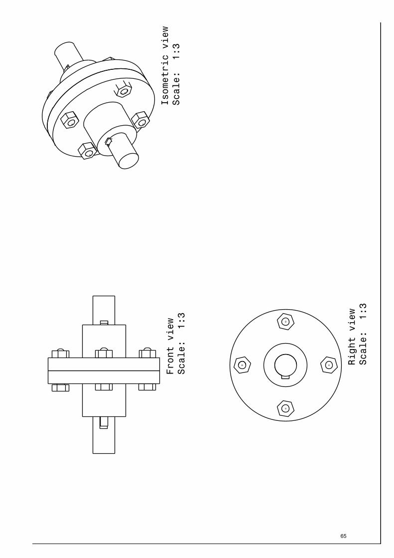
EX.NO 14 ASSEMBLY OF FLANGED COUPLING
DATE:
AIM:
Preparation of 3D Assembly model using CATIA V5.18 software
TOOLS USED:
Existing Component icon, Smart move, Constraining etc.,
PROCEDURE:
1. Assembly Design command is activated to launch the required workbench.
2. The commands for assembling parts are available in the toolbar on the right side of the
application window.
3. Click the Existing Component icon in the Product Structure toolbar, then the File
Selection dialog box is displayed were required the part model is selected.
4. To constrain a model for positioning parts correctly is carried using the various
constraints tools like Constraining and Manipulating and Select the fix component icon,
to Fix a part in the space.
5. Then t he p arts are a ssembled i n the f ollowing or der Flange(Male), Flange(Female),
Shaft, Key by adopting above methods
6. Select t he u pdate icon for assem bly to be upd ated, all ass embly de sign models ar e
ensured that it is in constraints condition before the models are finished.
64
vijaynandhu
Rectangle
65
vijaynandhu
Typewritten Text
NAME : REG.NO : CLASS : M.E CAD I YEAR
vijaynandhu
Rectangle
vijaynandhu
Rectangle

RESULT:
Thus the given 3D assembly model as per the drawing is modelled using CATIA V5.18 software.
66
vijaynandhu
Rectangle
67
vijaynandhu
Typewritten Text
NAME : REG.NO : CLASS : M.E CAD I YEAR
vijaynandhu
Rectangle
vijaynandhu
Rectangle
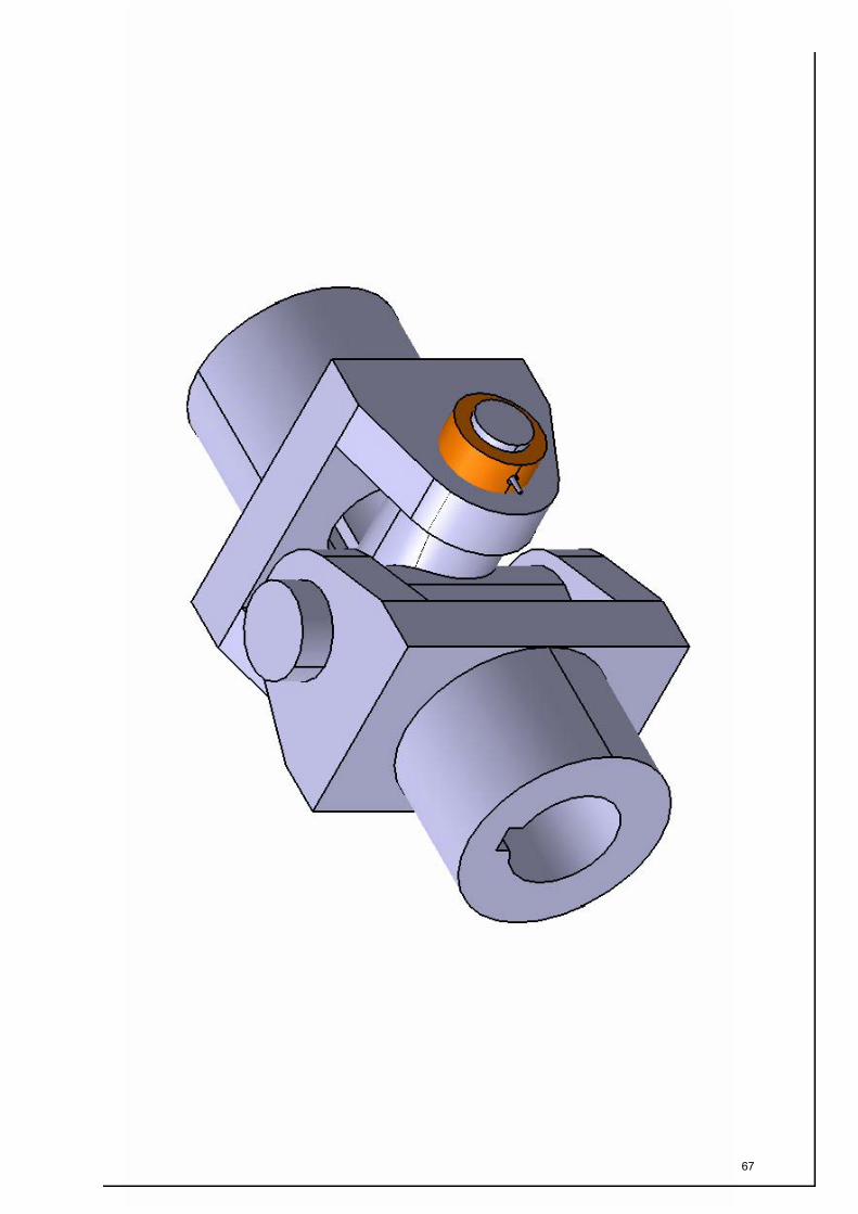
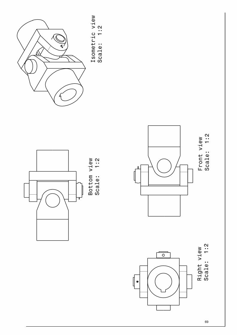
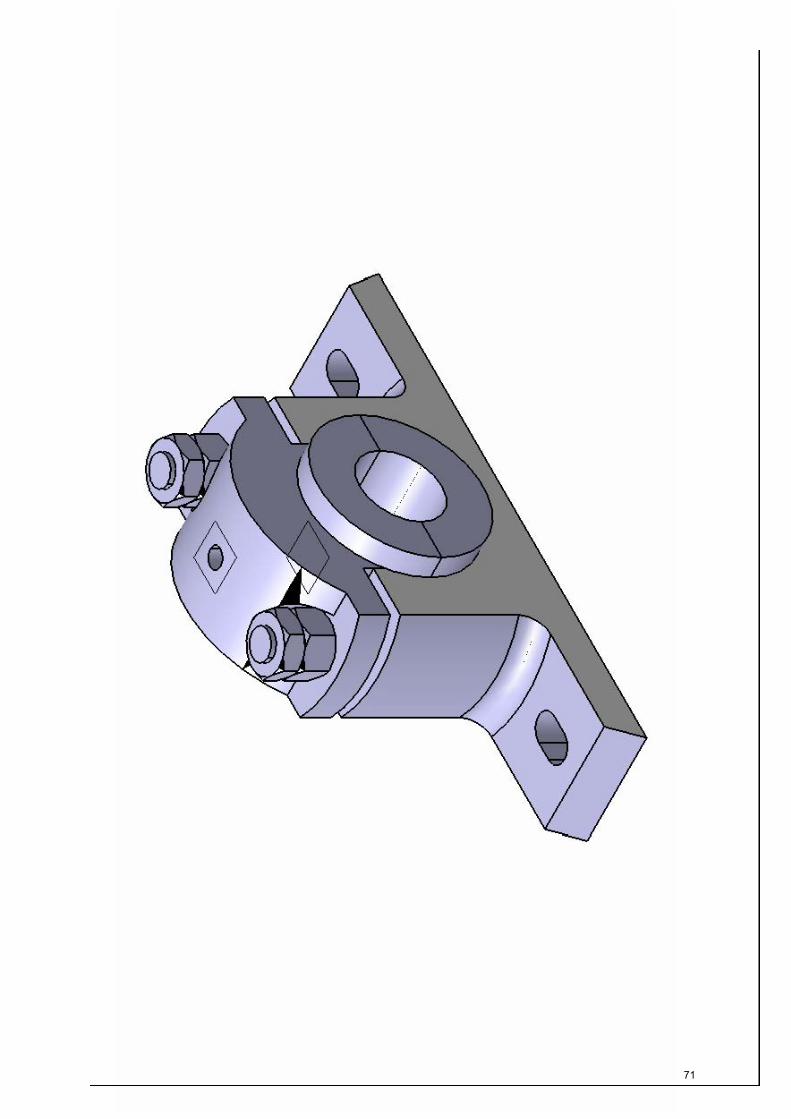
EX.NO 15 ASSEMBLY OF UNIVERSAL COUPLING
DATE:
AIM:
Preparation of 3D Assembly model using CATIA V5.18 software
TOOLS USED:
Existing Component icon, Smart move, Constraining etc.,
PROCEDURE:
1. Assembly Design command is activated to launch the required workbench.
2. The commands for assembling parts are available in the toolbar on the right side of the
application window.
3. Click the Existing Component icon in the Product Structure toolbar, then the File
Selection dialog box is displayed were required the part model is selected.
4. To constrain a model for positioning parts correctly is carried using the various
constraints tools like Constraining and Manipulating and Select the fix component icon,
to Fix a part in the space.
5. Then the parts are assembled in the following order Flange, Centre block, collar, Taper
pin by adopting above methods
6. Select t he u pdate icon for assem bly to be upd ated, all ass embly design m odels a re
ensured that it is in constraints condition before the models are finished.
68
vijaynandhu
Rectangle
69
vijaynandhu
Typewritten Text
NAME : REG.NO : CLASS : M.E CAD I YEAR
vijaynandhu
Rectangle
vijaynandhu
Rectangle
RESULT:
Thus the given 3D assembly model as per the drawing is modelled using CATIA V5.18 software.
70
vijaynandhu
Rectangle
71
vijaynandhu
Typewritten Text
NAME : REG.NO : CLASS : M.E CAD I YEAR
vijaynandhu
Rectangle
vijaynandhu
Rectangle

EX.NO 16 ASSEMBLY OF PLUMMER BLOCK
DATE:
AIM:
Preparation of 3D Assembly model using CATIA V5.18 software
TOOLS USED:
Existing Component icon, Smart move, Constraining etc.,
PROCEDURE:
1. Assembly Design command is activated to launch the required workbench.
2. The commands for assembling parts are available in the toolbar on the right side of the
application window.
3. Click the Existing Component icon in the Product Structure toolbar, then the File
Selection dialog box is displayed were required the part model is selected.
4. To constrain a model for positioning parts correctly is carried using the various
constraints tools like Constraining and Manipulating and Select the fix component icon,
to Fix a part in the space.
5. Then the pa rts ar e a ssembled in the following or der Body, Brass, Cap, Bolt & Nuts,
Lock Nuts by adopting above methods
6. Select t he u pdate icon for assem bly to be upd ated, all ass embly de sign models ar e
ensured that it is in constraints condition before the models are finished.
72
vijaynandhu
Rectangle

73
vijaynandhu
Typewritten Text
NAME : REG.NO : CLASS : M.E CAD I YEAR
vijaynandhu
Rectangle
vijaynandhu
Rectangle

RESULT:
Thus the given 3D assembly model as per the drawing is modelled using CATIA V5.18 software.
74
vijaynandhu
Rectangle
75
vijaynandhu
Typewritten Text
NAME : REG.NO : CLASS : M.E CAD I YEAR
vijaynandhu
Rectangle
vijaynandhu
Rectangle

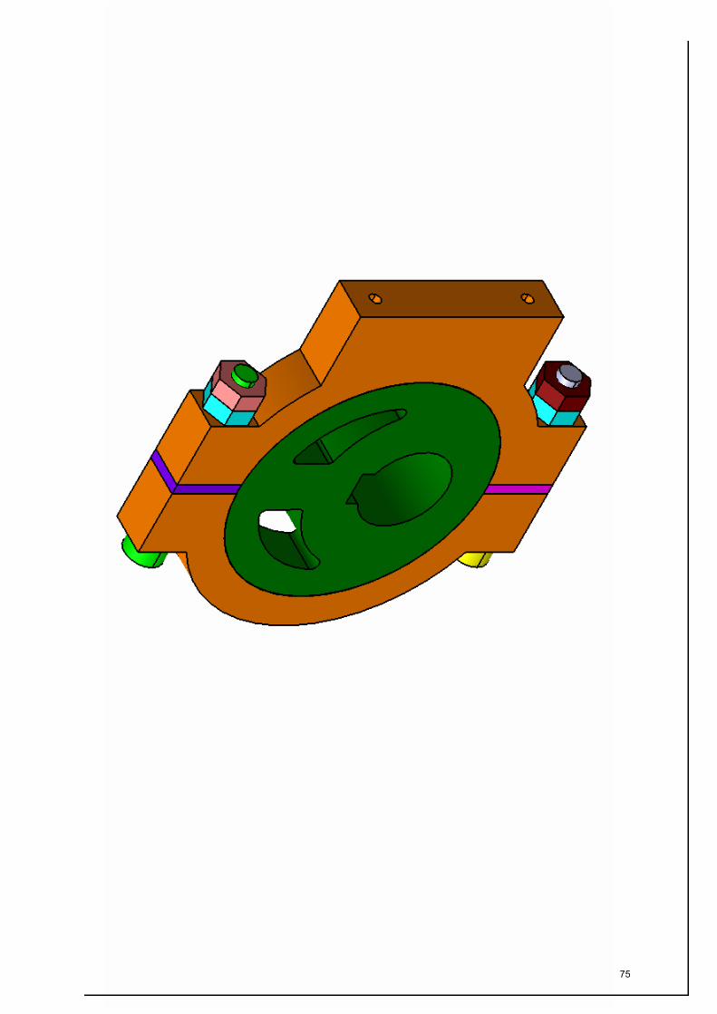
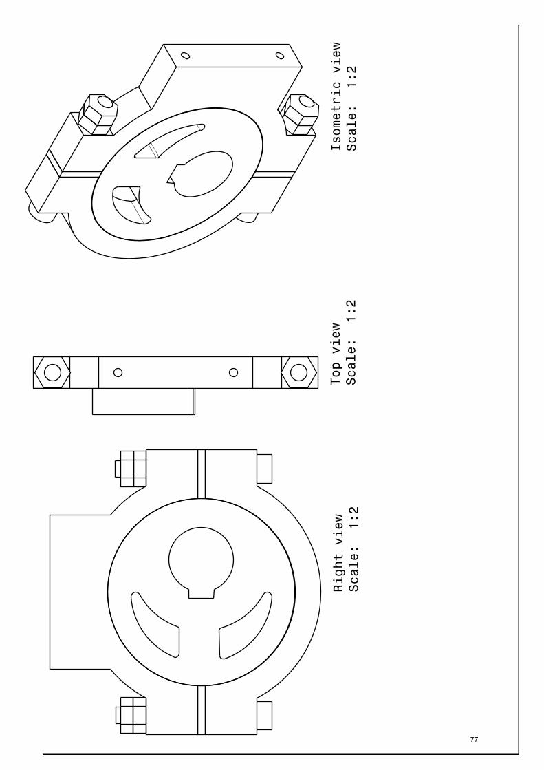
EX.NO 17 ASSEMBLY OF SIMPLE ECENTRIC
DATE:
AIM:
Preparation of 3D Assembly model using CATIA V5.18 software
TOOLS USED:
Existing Component icon, Smart move, Constraining etc.,
PROCEDURE:
1. Assembly Design command is activated to launch the required workbench.
2. The commands for assembling parts are available in the toolbar on the right side of the
application window.
3. Click the Existing Component icon in the Product Structure toolbar, then the File
Selection dialog box is displayed were required the part model is selected.
4. To constrain a model for positioning parts correctly is carried using the various
constraints tools like Constraining and Manipulating and Select the fix component icon,
to Fix a part in the space.
5. Then the parts are assembled in the following order Straps, Sheave, Shim, Headed bolt,
Nuts, Lock Nuts by adopting above methods
6. Select t he update icon for a ssembly t o b e upd ated, all a ssembly de sign m odels a re
ensured that it is in constraints condition before the models are finished.
76
vijaynandhu
Rectangle
77
vijaynandhu
Typewritten Text
NAME : REG.NO : CLASS : M.E CAD I YEAR
vijaynandhu
Rectangle
vijaynandhu
Rectangle

RESULT:
Thus the given 3D assembly model as per the drawing is modelled using CATIA V5.18 software.
78
vijaynandhu
Rectangle
79
vijaynandhu
Typewritten Text
NAME : REG.NO : CLASS : M.E CAD I YEAR
vijaynandhu
Rectangle
vijaynandhu
Rectangle

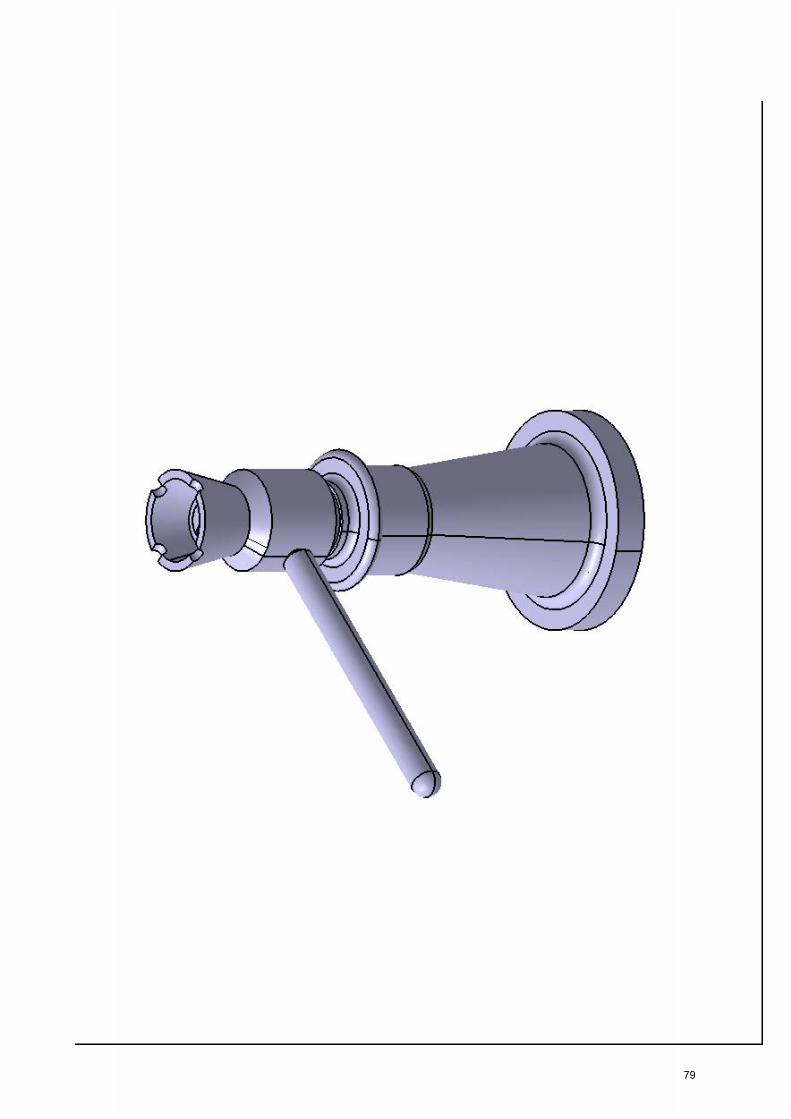
EX.NO 18 ASSEMBLY OF SCREW JACK
DATE:
AIM:
Preparation of 3D Assembly model using CATIA V5.18 software
TOOLS USED:
Existing Component icon, Smart move, Constraining etc.,
PROCEDURE:
1. Assembly Design command is activated to launch the required workbench.
2. The commands for assembling parts are available in the toolbar on the right side of the
application window.
3. Click the Existing Component icon in the Product Structure toolbar, then the File
Selection dialog box is displayed were required the part model is selected.
4. To constrain a model for positioning parts correctly is carried using the various
constraints tools like Constraining and Manipulating and Select the fix component icon,
to Fix a part in the space.
5. Then t he pa rts a re a ssembled i n t he f ollowing or der Body, Screw spindle, Nuts, Cup,
Tommy bar, Sunk screw, washer by adopting above methods
6. Select t he u pdate icon for assem bly to be upd ated, all ass embly de sign models ar e
ensured that it is in constraints condition before the models are finished.
80
vijaynandhu
Rectangle

81
vijaynandhu
Typewritten Text
NAME : REG.NO : CLASS : M.E CAD I YEAR
vijaynandhu
Rectangle
vijaynandhu
Rectangle
RESULT:
Thus the given 3D assembly model as per the drawing is modelled using CATIA V5.18 software.
82
vijaynandhu
Rectangle

83
vijaynandhu
Typewritten Text
NAME : REG.NO : CLASS : M.E CAD I YEAR
vijaynandhu
Rectangle
vijaynandhu
Rectangle

EX.NO 19 ASSEMBLY OF STUFFING BOX
DATE:
AIM:
Preparation of 3D Assembly model using CATIA V5.18 software
TOOLS USED:
Existing Component icon, Smart move, Constraining etc.,
PROCEDURE:
1. Assembly Design command is activated to launch the required workbench.
2. The commands for assembling parts are available in the toolbar on the right side of the
application window.
3. Click the Existing Component icon in the Product Structure toolbar, then the File
Selection dialog box is displayed were required the part model is selected.
4. To constrain a model for positioning parts correctly is carried using the various
constraints tools like Constraining and Manipulating and Select the fix component icon,
to Fix a part in the space.
5. Then the parts are assembled in the following order Body, Neck bush, gland bush, gland
Shaft by adopting above methods
6. Select t he u pdate icon for assem bly to be upd ated, all ass embly de sign models ar e
ensured that it is in constraints condition before the models are finished.
84
vijaynandhu
Rectangle

85
vijaynandhu
Typewritten Text
NAME : REG.NO : CLASS : M.E CAD I YEAR
vijaynandhu
Rectangle
vijaynandhu
Rectangle

RESULT:
Thus the given 3D assembly model as per the drawing is modelled using CATIA V5.18 software.
86
vijaynandhu
Rectangle

87
vijaynandhu
Typewritten Text
NAME : REG.NO : CLASS : M.E CAD I YEAR
vijaynandhu
Rectangle
vijaynandhu
Rectangle
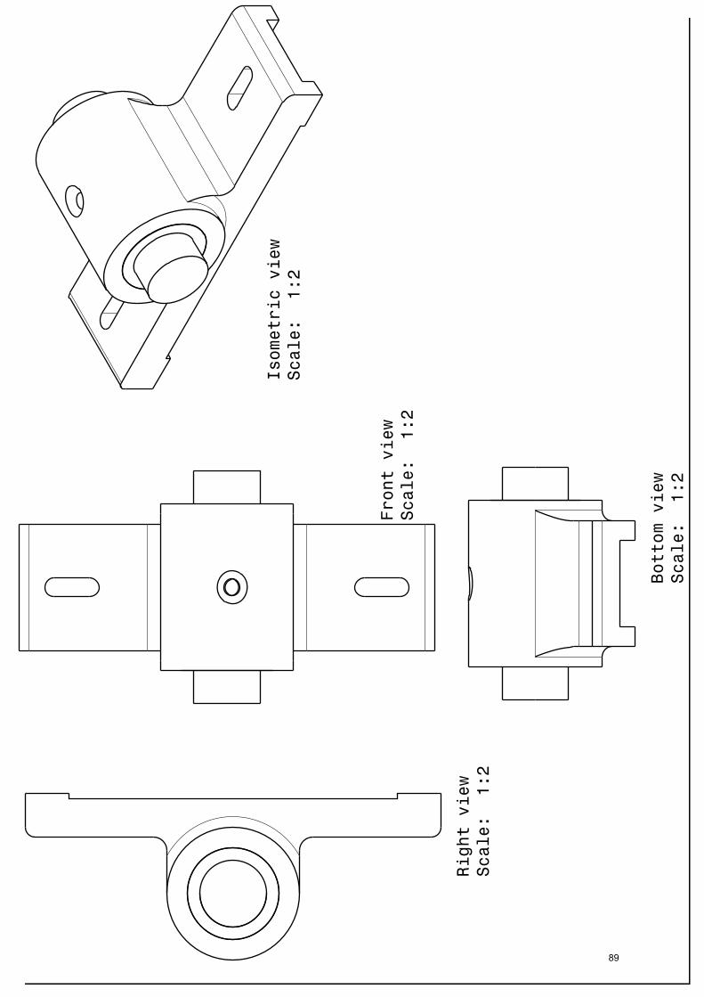
EX.NO 20 ASSEMBLY OF BUSHED BEARING
DATE:
AIM:
Preparation of 3D Assembly model using CATIA V5.18 software
TOOLS USED:
Existing Component icon, Smart move, Constraining etc.,
PROCEDURE:
1. Assembly Design command is activated to launch the required workbench.
2. The commands for assembling parts are available in the toolbar on the right side of the
application window.
3. Click the Existing Component icon in the Product Structure toolbar, then the File
Selection dialog box is displayed were required the part model is selected.
4. To constrain a model for positioning parts correctly is carried using the various
constraints tools like Constraining and Manipulating and Select the fix component icon,
to Fix a part in the space.
5. Then t he pa rts are a ssembled i n the f ollowing or der Body, Bush, Shaft by a dopting
above methods
6. Select t he u pdate icon for assem bly to be upd ated, all ass embly de sign models ar e
ensured that it is in constraints condition before the models are finished.
88
vijaynandhu
Rectangle
89
vijaynandhu
Rectangle

RESULT:
Thus the given 3D assembly model as per the drawing is modelled using CATIA V5.18 software.
90
vijaynandhu
Rectangle