
Caterpillar 236B-246B-252B Y 262B
22
Testing and Adjusting 236B, 246B, 252B and 262B Skid Steer Loaders Hydraulic System Media Number -RENR4867-03 Publication Date -01/11/2009 Date Updated -24/11/2009 i03177701 Hydrostatic System - Test and Adjust SMCS - 4350-025; 4350-081 Required Tools Part number Description Quantity 6V-4143 Quick Connect Coupler 10 177-7861 Hose As 5 6V-3989 Fitting As 6 6V-3966 Fitting As 2 8T-0855 Pressure Gauge 0 to 4000 kPa (580 psi) 3 8T-0854 Pressure Gauge 0 to 1000 kPa (145 psi) 1 8T-0860 Pressure Gauge 0 to 40000 kPa (5802 psi) 1 186-2613 Pressure Gauge 0 to 70000 kPa (10153 psi) 2 1U-5796 Pressure Differential Tool Gp 1 164-3310 Infrared Thermometer 1 9U-7400 Multitach Tool Gp 1 1U-6605 Reflective Tape 1 7X-2444 Swivel Tee 1 Table 1
-
Upload
victor-montesdeoca -
Category
Documents
-
view
130 -
download
13
description
caterpillar motores 6d16
Transcript of Caterpillar 236B-246B-252B Y 262B
Testing and Adjusting236B, 246B, 252B and 262B Skid Steer Loaders Hydraulic System
Media Number -RENR4867-03 Publication Date -01/11/2009 Date Updated -24/11/2009
i03177701
Hydrostatic System - Test and Adjust
SMCS - 4350-025; 4350-081
Required Tools
Part number Description Quantity
6V-4143 Quick Connect Coupler 10
177-7861 Hose As 5
6V-3989 Fitting As 6
6V-3966 Fitting As 2
8T-0855 Pressure Gauge 0 to 4000 kPa (580 psi) 3
8T-0854Pressure Gauge 0 to
1000 kPa (145 psi)1
8T-0860Pressure Gauge 0 to
40000 kPa (5802 psi)1
186-2613 Pressure Gauge 0 to70000 kPa (10153 psi)
2
1U-5796 Pressure Differential Tool Gp 1
164-3310 Infrared Thermometer 1
9U-7400 Multitach Tool Gp 1
1U-6605 Reflective Tape 1
7X-2444 Swivel Tee 1
Table 1
4J-5477 O-Ring Seal 1
5P-2937 O-Ring Adapter 1
3J-7354 O-Ring Seal 1
Install a 6V-4143 Quick Connect Coupler to each end of the 177-7861 Hose As . Install a 6V-3989Fitting to the 8T-0855 . Install a 6V-3989 Fitting to the 8T-0854 Pressure Gauge . You will also needto install a 6V-3989 Fitting to the 186-2613 Pressure Gauge .
Install a 6V-3966 Fitting As into both of the 7X-2444 Swivel Tee and the 5P-2937 O-Ring Adapter .
Sudden movement of the machine or release of oil under pressure cancause injury to persons on or near the machine.
To prevent possible injury, perform the procedure that follows beforetesting and adjusting the power train.
NOTICE
Care must be taken to ensure that fluids are contained duringperformance of inspection, maintenance, testing, adjusting and repairof the product. Be prepared to collect the fluid with suitable containers
before opening any compartment or disassembling any componentcontaining fluids.
Refer to Special Publication, NENG2500, "Caterpillar Dealer ServiceTool Catalog" for tools and supplies suitable to collect and contain
fluids on Caterpillar products.
Dispose of all fluids according to local regulations and mandates.
Before any tests are performed, prepare the machine. Refer to Testing and Adjusting, "MachinePreparation". Before any tests are performed, visually inspect the complete hydraulic system for oilleaks and damaged parts. Refer to Testing and Adjusting, "Visual Inspection".
The tests for the hydraulic system should be done in the following order. In order for the hydrostaticsystem to function correctly, each component in the system must be set to the correct specifications.Some components must be set prior to the testing of other components. A component that is not setcorrectly will have an impact on other components in the system.
It is not advisable to bypass preceding tests. Do not perform a test before the tests that precede thattest have been done. Table 1 lists the equipment that is needed to perform testing on the hydrostaticsystem. Equivalent tooling may be substituted.
Clearly mark all of the hoses and the corresponding pressure gauges, when the hoses are installed.The hoses and the pressure gauges will be used multiple times in the testing and adjusting procedures.
Throughout the entire testing procedure, MB pressure refers to the hydraulic oil pressure in theforward hydrostatic loop. MA pressure refers to the hydraulic oil pressure in the reverse hydrostaticloop.
Note: The oil in the hydraulic system must be at an operating temperature of 45° ± 5°C (113° ± 9° F).This temperature range is specified for only the standard oil from the factory. Use the 164-3310Infrared Thermometer or the equivalent to measure this temperature at the hydraulic filter. In order toincrease the hydraulic system temperature, start the engine and operate all hydraulic cylinders for atleast five cycles. Move the machine in the forward and reverse directions. Move the work toolthrough the full range of motion.
Baseline for the Hydrostatic System
Use cribbing to elevate the machine. The wheels must not touch the ground.1.
Release the hydraulic system pressure. Refer to Testing and Adjusting, "Hydraulic SystemPressure - Release" for the correct procedure.
2.
Raise the cab. Refer to Operation and Maintenance Manual, "Cab Support Operation" for thecorrect procedure.
3.
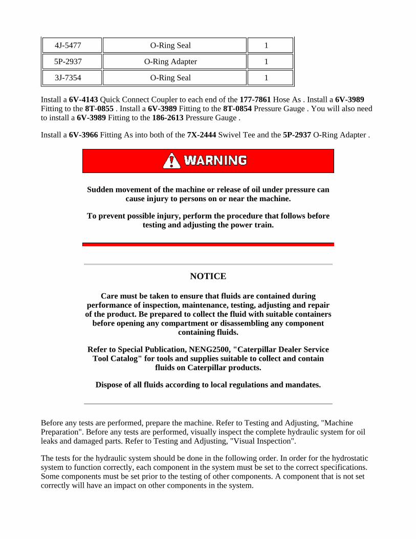
Illustration 1 g00788958
(1) Charge pressure tap
Install the 177-7861 Hose to the charge pressure tap (1) on the right side of the hydrostaticpiston pump. Connect the 8T-0855 Pressure Gauge to the other end of this hose. Place the hosein a visible position.
4.
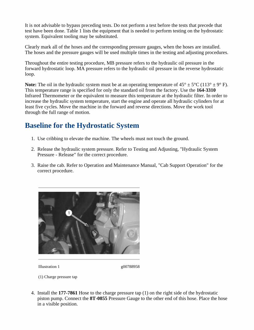
Illustration 2 g00788976
(2) Speed sensing pressure tap
Install the 177-7861 Hose to the speed sensing pressure tap (2) . The speed sensing pressure tapis located on the top of the hydrostatic piston pump. Connect the 8T-0855 Pressure Gauge tothe other end of this hose. Place the hose in a visible position.
5.
Illustration 3 g00592868
Install the 9U-7400 Multitach Tool Gp on the rear frame and position the sensor in order to pickup the reflective tape on the crankshaft pulley.
6.
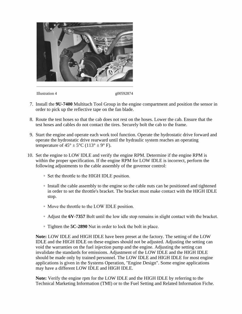
Illustration 4 g00592874
Install the 9U-7400 Multitach Tool Group in the engine compartment and position the sensor inorder to pick up the reflective tape on the fan blade.
7.
Route the test hoses so that the cab does not rest on the hoses. Lower the cab. Ensure that thetest hoses and cables do not contact the tires. Securely bolt the cab to the frame.
8.
Start the engine and operate each work tool function. Operate the hydrostatic drive forward andoperate the hydrostatic drive rearward until the hydraulic system reaches an operatingtemperature of 45° ± 5°C (113° ± 9° F).
9.
Set the engine to LOW IDLE and verify the engine RPM. Determine if the engine RPM iswithin the proper specification. If the engine RPM for LOW IDLE is incorrect, perform thefollowing adjustments to the cable assembly of the governor control:
10.
Set the throttle to the HIGH IDLE position.◦
Install the cable assembly to the engine so the cable nuts can be positioned and tightenedin order to set the throttle's bracket. The bracket must make contact with the HIGH IDLEstop.
◦
Move the throttle to the LOW IDLE position.◦
Adjust the 6V-7357 Bolt until the low idle stop remains in slight contact with the bracket.◦
Tighten the 5C-2890 Nut in order to lock the bolt in place.◦
Note: LOW IDLE and HIGH IDLE have been preset at the factory. The setting of the LOWIDLE and the HIGH IDLE on these engines should not be adjusted. Adjusting the setting canvoid the warranties on the fuel injection pump and the engine. Adjusting the setting caninvalidate the standards for emissions. Adjustment of the LOW IDLE and the HIGH IDLEshould be made only by trained personnel. The LOW IDLE and HIGH IDLE for most engineapplications is given in the Systems Operation, "Engine Design". Some engine applicationsmay have a different LOW IDLE and HIGH IDLE.
Note: Verify the engine rpm for the LOW IDLE and the HIGH IDLE by referring to theTechnical Marketing Information (TMI) or to the Fuel Setting and Related Information Fiche.

Model Low Idle Engine RPM
236B/ 246B/ 252B/ 262B 1000 ± 50 RPM
Table 2
Record the following items at LOW IDLE: engine RPM, charge pressure and speed sensingpressure.
11.
Model Charge PressurePressure for Speed Sensing
Oil Temperature Range
45° ± 5°C (113° ± 9°F)
236B/ 246B/ 252B/ 262B3100 ± 200 kPa (450 ± 29 psi) 950 ± 200 kPa (138 ± 29 psi)
Table 3
Increase the engine speed to HIGH IDLE.12.
If the engine speed for HIGH IDLE is incorrect, perform the following checks:
Set the throttle to the HIGH IDLE position.◦
Install the cable assembly to the engine so the cable nuts can be positioned and tightenedin order to set the throttle's bracket. The bracket must make contact with the high idlestop.
◦
Move the throttle to the LOW IDLE position.◦
Adjust the 6V-7357 Bolt until the LOW IDLE stop remains in slight contact with thebracket.
◦
Tighten the 5C-2890 Nut in order to lock the bolt in place.◦
Note: Low idle and high idle have been preset at the factory. The setting of the LOW IDLE andthe HIGH IDLE on these engines should not be adjusted. Adjusting the setting can void thewarranties on the fuel injection pump and the engine. Adjusting the setting can invalidate thestandards for emissions. Adjustment of the LOW IDLE and the HIGH IDLE should be madeonly by trained personnel. LOW IDLE and HIGH IDLE for most engine applications is given inthe Systems Operation, "Engine Design". Some engine applications may have a different LOWIDLE and HIGH IDLE.
Model High Idle Engine RPM
236B/ 246B/ 252B/ 262B 2860 ± 50 RPM
Table 4
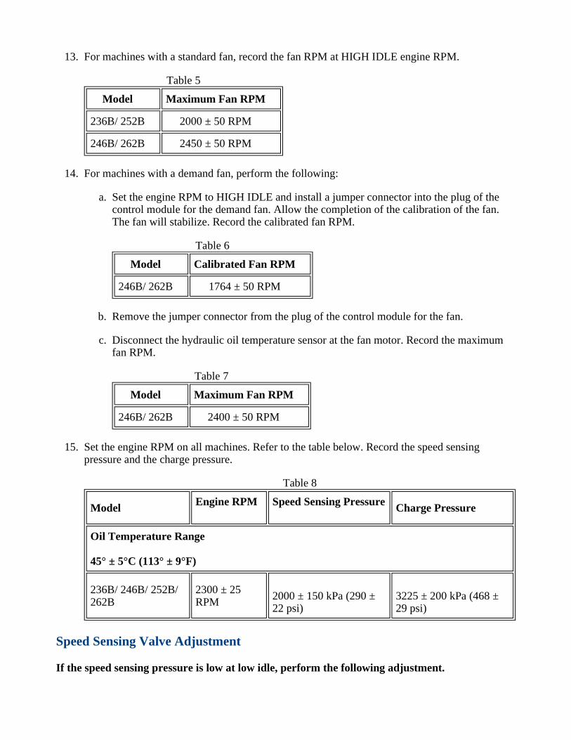
For machines with a standard fan, record the fan RPM at HIGH IDLE engine RPM.13.
Model Maximum Fan RPM
236B/ 252B 2000 ± 50 RPM
246B/ 262B 2450 ± 50 RPM
Table 5
For machines with a demand fan, perform the following:14.
Set the engine RPM to HIGH IDLE and install a jumper connector into the plug of thecontrol module for the demand fan. Allow the completion of the calibration of the fan.The fan will stabilize. Record the calibrated fan RPM.
a.
Model Calibrated Fan RPM
246B/ 262B 1764 ± 50 RPM
Table 6
Remove the jumper connector from the plug of the control module for the fan.b.
Disconnect the hydraulic oil temperature sensor at the fan motor. Record the maximumfan RPM.
c.
Model Maximum Fan RPM
246B/ 262B 2400 ± 50 RPM
Table 7
Set the engine RPM on all machines. Refer to the table below. Record the speed sensingpressure and the charge pressure.
15.
ModelEngine RPM Speed Sensing Pressure
Charge Pressure
Oil Temperature Range
45° ± 5°C (113° ± 9°F)
236B/ 246B/ 252B/262B
2300 ± 25RPM
2000 ± 150 kPa (290 ±22 psi)
3225 ± 200 kPa (468 ±29 psi)
Table 8
Speed Sensing Valve Adjustment
If the speed sensing pressure is low at low idle, perform the following adjustment.
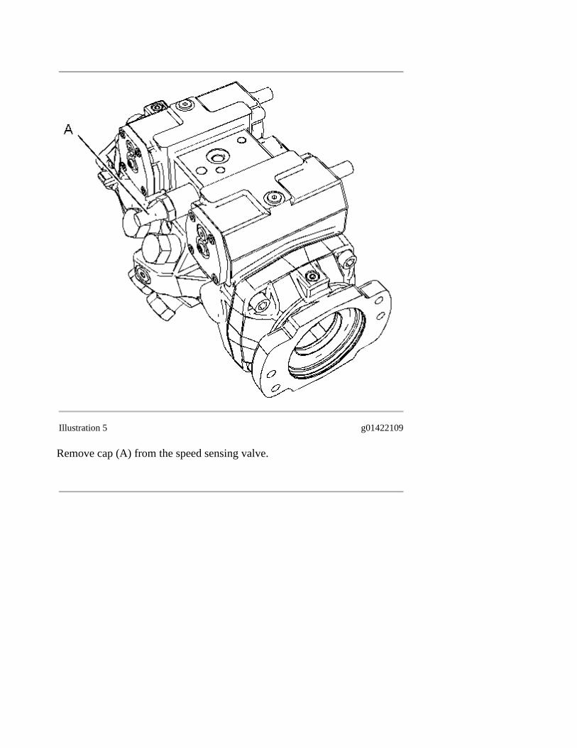
Illustration 5 g01422109
Remove cap (A) from the speed sensing valve.
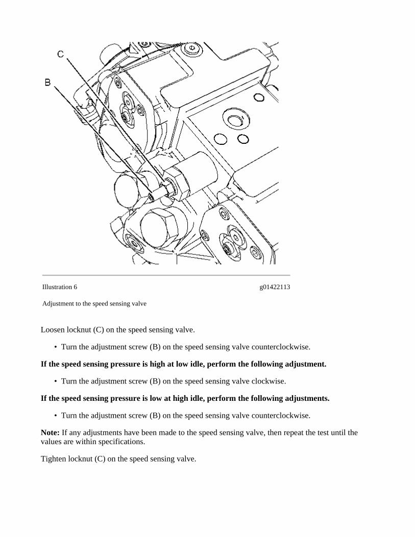
Illustration 6 g01422113
Adjustment to the speed sensing valve
Loosen locknut (C) on the speed sensing valve.
Turn the adjustment screw (B) on the speed sensing valve counterclockwise.•
If the speed sensing pressure is high at low idle, perform the following adjustment.
Turn the adjustment screw (B) on the speed sensing valve clockwise.•
If the speed sensing pressure is low at high idle, perform the following adjustments.
Turn the adjustment screw (B) on the speed sensing valve counterclockwise.•
Note: If any adjustments have been made to the speed sensing valve, then repeat the test until thevalues are within specifications.
Tighten locknut (C) on the speed sensing valve.

Start To Move Test
Perform the start to move test in order to verify that forward and reverse machine movement beginswithin specified time after the operator initiates a command.
Perform the Hydrostatic System Baseline Test before testing for start to move.1.
Start the engine and operate each work tool function. Operate the hydrostatic drive forward andoperate the hydrostatic drive rearward. Operate until the hydraulic system reaches an operatingtemperature of 45° ± 5°C (113° ± 9° F).
2.
Set the engine speed to LOW IDLE.3.
Quickly move the joystick control for drive into forward to the 12 o'clock position. Capture thetime until the machine moves. Use a stopwatch to measure the specifications. Immediatelyreturn the joystick to the neutral position.
4.
Repeat four times. Calculate the average in order to determine the Forward Start to Move time.5.
Quickly move the joystick control for drive into rearward to the 6 o'clock position. Capture thetime until the machine moves. Use a stopwatch to measure the specifications. Immediatelyreturn the joystick to the neutral position.
6.
Repeat four times. Calculate the average in order to determine the Forward Start to Move time.7.
Model Start to Move Forward. Start to Move Reverse.
236B/ 246B/ 252B/ 262B 1 second max 1.5 seconds max
Table 9
Pump Neutral Position Test
Perform the test for the neutral position of the pump in order to make sure that the piston pump issynchronized. If the pump is not synchronized, the machine could drift or the machine could movewith the pilot operated hydraulic control ( hydrostatic) in the NEUTRAL position. If the pump is notsynchronized, the wheel on one side of the machine could start to move before the wheel on the otherside of the machine starts to move.
Note: If the left wheel and the right wheel start to move at the same time, this test is notrequired.
Use cribbing to elevate the machine. The wheels must not touch the ground. Make sure that allhoses are out of the way of the rotating wheels.
1.
Sit in the operator's seat. Fasten the seat belt and lower the armrest.2.
Start the engine and run the engine at LOW idle.3.
Move the pilot operated hydraulic control ( hydrostatic) slowly forward. Check that the leftwheel and the right wheel start to move at the same time. If the left wheel and the right wheel
4.
start to move at the same time, proceed to the "Maximum Runout"test. If the left wheel and theright wheel do not start to move at the same time, proceed to step 5.
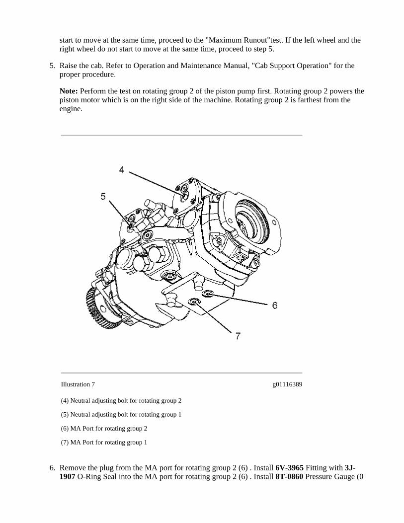
Raise the cab. Refer to Operation and Maintenance Manual, "Cab Support Operation" for theproper procedure.
5.
Note: Perform the test on rotating group 2 of the piston pump first. Rotating group 2 powers thepiston motor which is on the right side of the machine. Rotating group 2 is farthest from theengine.
Illustration 7 g01116389
(4) Neutral adjusting bolt for rotating group 2
(5) Neutral adjusting bolt for rotating group 1
(6) MA Port for rotating group 2
(7) MA Port for rotating group 1
Remove the plug from the MA port for rotating group 2 (6) . Install 6V-3965 Fitting with 3J-1907 O-Ring Seal into the MA port for rotating group 2 (6) . Install 8T-0860 Pressure Gauge (0
6.

to 40000 kPa) to the MA port for rotating group 2 (6) with the following items: 6V-3989Fitting , two 6V-4143 Quick Connect Couplers and 177-7860 Hose .
Illustration 8 g01116394
(8) MB Port for rotating group 2
(9) MB Port for rotating group 1
Install 8T-0860 Pressure Gauge (0 to 40000 kPa) to the MB port for rotating group 2 (8) withthe following items: 6V-3989 Fitting , two 6V-4143 Quick Connect Couplers and 177-7860Hose .
7.
Place the two gauges in an easily visible position.8.
Lower the cab. Route the test hoses so that the cab does not rest on any of the hoses.9.
Fasten the seat belt and lower the armrest.10.
Start the engine and run the engine at LOW idle.11.
Raise the cab.12.
Loosen the locknut for the neutral adjusting bolt. Do not use an impact socket.13.
Turn neutral adjustment screw for rotating group 2 (4) clockwise. Mark the location of theneutral adjusting bolt when the MB pressure begins to increase.
14.
Turn neutral adjustment screw (4) counterclockwise. Mark the location of the neutral adjustingbolt when the MA pressure begins to increase.
15.
Turn the neutral adjustment screw (4) midway between the two marks.16.
Hold the neutral adjustment screw (4) in position as you tighten the locknut to a torque of 30.0± 1.5 N·m (22.1 ± 1.1 lb ft).
17.
Lower the cab.18.
Note: In the next step, the wheels will rotate. Make sure that all hoses are out of the way of therotating wheels.
Move the pilot operated hydraulic control ( hydrostatic) slowly forward. Check that the leftwheel and the right wheel start to move at the same time.
19.
If the wheels do not start to move at the same time, then repeat this adjustment procedure forrotating group 1.
20.
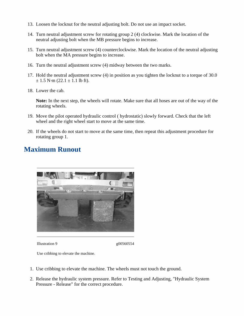
Maximum Runout
Illustration 9 g00560554
Use cribbing to elevate the machine.
Use cribbing to elevate the machine. The wheels must not touch the ground.1.
Release the hydraulic system pressure. Refer to Testing and Adjusting, "Hydraulic SystemPressure - Release" for the correct procedure.
2.
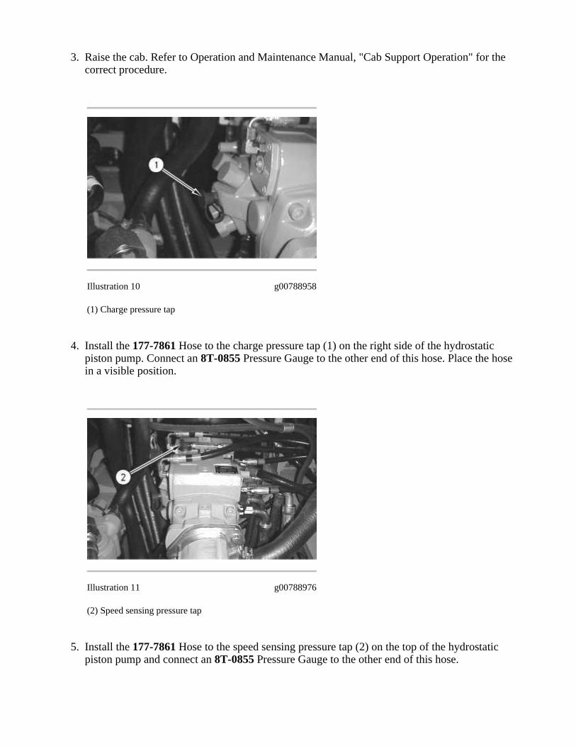
Raise the cab. Refer to Operation and Maintenance Manual, "Cab Support Operation" for thecorrect procedure.
3.
Illustration 10 g00788958
(1) Charge pressure tap
Install the 177-7861 Hose to the charge pressure tap (1) on the right side of the hydrostaticpiston pump. Connect an 8T-0855 Pressure Gauge to the other end of this hose. Place the hosein a visible position.
4.
Illustration 11 g00788976
(2) Speed sensing pressure tap
Install the 177-7861 Hose to the speed sensing pressure tap (2) on the top of the hydrostaticpiston pump and connect an 8T-0855 Pressure Gauge to the other end of this hose.
5.
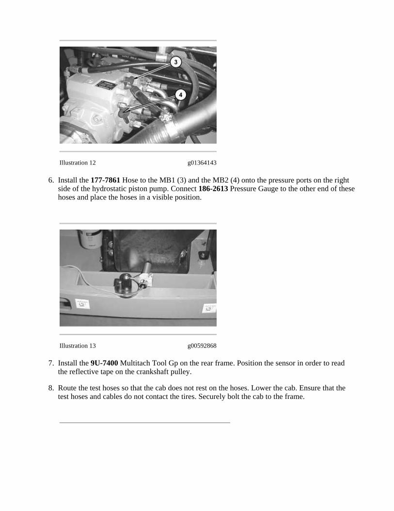
Illustration 12 g01364143
Install the 177-7861 Hose to the MB1 (3) and the MB2 (4) onto the pressure ports on the rightside of the hydrostatic piston pump. Connect 186-2613 Pressure Gauge to the other end of thesehoses and place the hoses in a visible position.
6.
Illustration 13 g00592868
Install the 9U-7400 Multitach Tool Gp on the rear frame. Position the sensor in order to readthe reflective tape on the crankshaft pulley.
7.
Route the test hoses so that the cab does not rest on the hoses. Lower the cab. Ensure that thetest hoses and cables do not contact the tires. Securely bolt the cab to the frame.
8.
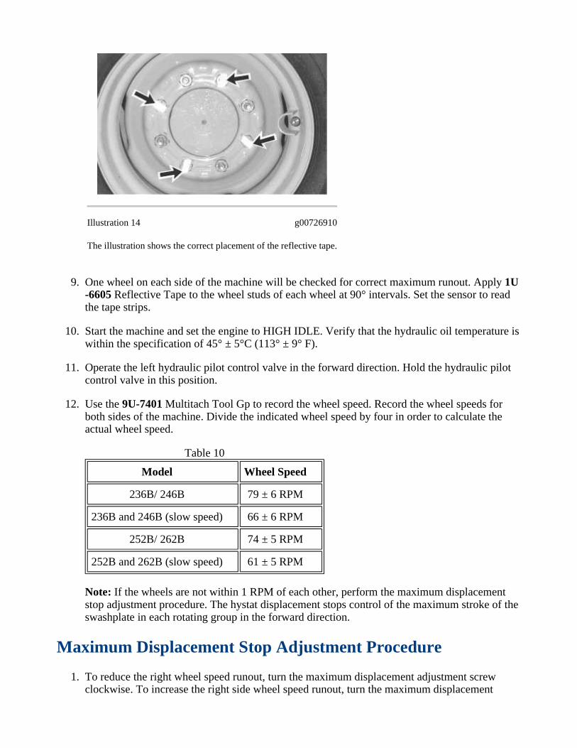
Illustration 14 g00726910
The illustration shows the correct placement of the reflective tape.
One wheel on each side of the machine will be checked for correct maximum runout. Apply 1U-6605 Reflective Tape to the wheel studs of each wheel at 90° intervals. Set the sensor to readthe tape strips.
9.
Start the machine and set the engine to HIGH IDLE. Verify that the hydraulic oil temperature iswithin the specification of 45° ± 5°C (113° ± 9° F).
10.
Operate the left hydraulic pilot control valve in the forward direction. Hold the hydraulic pilotcontrol valve in this position.
11.
Use the 9U-7401 Multitach Tool Gp to record the wheel speed. Record the wheel speeds forboth sides of the machine. Divide the indicated wheel speed by four in order to calculate theactual wheel speed.
12.
Model Wheel Speed
236B/ 246B 79 ± 6 RPM
236B and 246B (slow speed) 66 ± 6 RPM
252B/ 262B 74 ± 5 RPM
252B and 262B (slow speed) 61 ± 5 RPM
Table 10
Note: If the wheels are not within 1 RPM of each other, perform the maximum displacementstop adjustment procedure. The hystat displacement stops control of the maximum stroke of theswashplate in each rotating group in the forward direction.
Maximum Displacement Stop Adjustment Procedure
To reduce the right wheel speed runout, turn the maximum displacement adjustment screwclockwise. To increase the right side wheel speed runout, turn the maximum displacement
1.
adjustment screw counterclockwise. The right side maximum displacement adjustment screw islocated on the right side of the hydrostatic pump farthest from the engine. Make adjustments byturning the screw in increments of 1/8 of a turn and recheck using the maximum runout test.
To reduce the left side wheel speed runout, turn the maximum displacement adjustment screwclockwise. To increase the left side wheel speed runout, turn the maximum displacementadjustment screw counterclockwise. The left side maximum displacement adjustment screw islocated on the right side of the hydrostatic pump. Make adjustments by turning the screw inincrements of 1/8 of a turn and recheck using the maximum runout test.
2.
Once the right and left wheel speeds are within the specification, tighten the adjustment screwand the adjustment screw locknut to 22 ± 1 N·m (16.2 ± 0.7 lb ft) and install a 6E-5060 CapAs .
3.
Stall Test
Sudden movement of the machine or release of oil under pressure cancause injury to persons on or near the machine.
To prevent possible injury, perform the procedure that follows beforetesting and adjusting the power train.
Personal injury can result from hydraulic oil pressure and hot oil.
Hydraulic oil pressure can remain in the hydraulic system after theengine has been stopped. Serious injury can be caused if this pressure is
not released before any service is done on the hydraulic system.
Make sure all of the attachments have been lowered, oil is cool beforeremoving any components or lines. Remove the oil filler cap only when
the engine is stopped, and the filler cap is cool enough to touch withyour bare hand.
The test can be used in order to identify low power problems with the engine. The test is also used toidentify the crossover relief valves that may be malfunctioning.
Raise the cab. Refer to Operations and Maintenance Manual, "Cab Support Operation" for thecorrect procedure.
1.
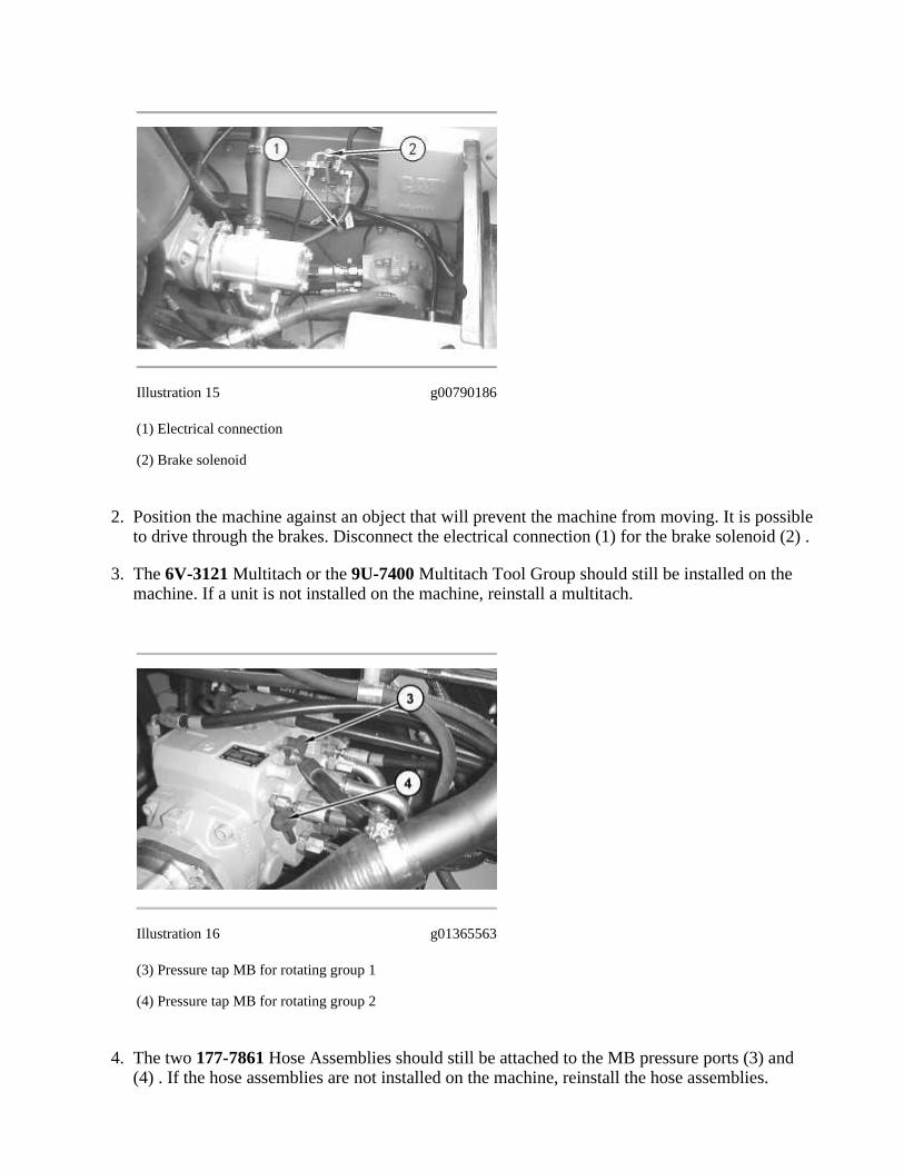
Illustration 15 g00790186
(1) Electrical connection
(2) Brake solenoid
Position the machine against an object that will prevent the machine from moving. It is possibleto drive through the brakes. Disconnect the electrical connection (1) for the brake solenoid (2) .
2.
The 6V-3121 Multitach or the 9U-7400 Multitach Tool Group should still be installed on themachine. If a unit is not installed on the machine, reinstall a multitach.
3.
Illustration 16 g01365563
(3) Pressure tap MB for rotating group 1
(4) Pressure tap MB for rotating group 2
The two 177-7861 Hose Assemblies should still be attached to the MB pressure ports (3) and(4) . If the hose assemblies are not installed on the machine, reinstall the hose assemblies.
4.

Route the test hoses and cables so that the cab will not rest on the hoses and cables. Properlysecure the cab.
5.
Sit in the operator's seat and fasten the seat belt. Lower the armrest.6.
Start the engine and run the engine at LOW IDLE.7.
Slowly increase the engine speed to HIGH IDLE.8.
Push the pilot operated hydraulic control to the FORWARD position until the engine RPMstabilizes.
9.
Note: Do not continue to stall the hydrostatic system for more than 15 seconds. Damage to themachine may result.
Note: The wheels should not spin. If the wheels spin, refer to the Testing and Adjusting, "BrakeTest".
Record the engine stall speed. Record the MB1 and MB2 pressure values.10.
Model Engine Stall MB1 Pressure MB2 Pressure
236B/ 246B/ 252B/262B
2700 ± 200RPM
38300 ± 2000 kPa (5555 ±290 psi)
38300 ± 2000 kPa (5555 ±290 psi)
Table 11
If the engine stall RPM is not correct, refer to the troubleshooting section.
If the MB pressures are not within the specification, the crossover relief valves may need to beadjusted. Refer to the procedure below.
Remove the cap of the crossover relief valve that is not within the specification. Remove thespring and the crossover relief valve.
1.
Illustration 17 g01365567

Place crossover relief valve (5) into a vise.2.
Turn the set screw (6) counterclockwise in order to loosen the setscrew.3.
Illustration 18 g01365572
Place retainer (7) of the crossover relief valve in a vise. Turn adjustment screw (8) in order toadjust the relief pressure. Turn the adjustment screw clockwise in order to increase the pressureor turn the adjustment screw counterclockwise in order to decrease the pressure. One full turnof the adjustment screw is approximately 6400 kPa (928 psi).
4.
Note: When you adjust the crossover relief valve to decrease the pressure, turn the adjustmentscrew for an additional 1/4 turn past the estimated adjustment setting. Then, turn the adjustmentscrew clockwise for 1/4 turn.
Tighten setscrew (6) to a torque of 6.5 N·m (58 lb in).5.
Install crossover relief valve (5) , the spring, and the cap. Tighten the cap to a torque of 160 ±10 N·m (118 ± 7 lb ft).
6.
Double Stall Test
The test will determine if engine performance is low.
Note: The 6V-3121 Multitach or the 9U-7400 Multitach Tool Group should still be installed on themachine. If the unit is not installed, reinstall the unit.
Position the machine against an object that will prevent the machine from moving. It is possibleto drive through the brakes.
1.
Raise the cab. Refer to the Operations and Maintenance Manual, "Cab Support Operation" forthe correct procedure.
2.
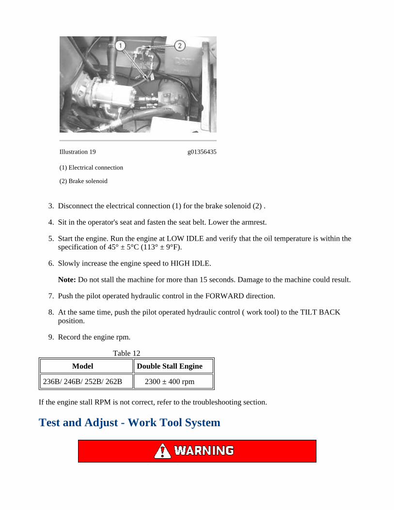
Illustration 19 g01356435
(1) Electrical connection
(2) Brake solenoid
Disconnect the electrical connection (1) for the brake solenoid (2) .3.
Sit in the operator's seat and fasten the seat belt. Lower the armrest.4.
Start the engine. Run the engine at LOW IDLE and verify that the oil temperature is within thespecification of 45° ± 5°C (113° ± 9°F).
5.
Slowly increase the engine speed to HIGH IDLE.6.
Note: Do not stall the machine for more than 15 seconds. Damage to the machine could result.
Push the pilot operated hydraulic control in the FORWARD direction.7.
At the same time, push the pilot operated hydraulic control ( work tool) to the TILT BACKposition.
8.
Record the engine rpm.9.
Model Double Stall Engine
236B/ 246B/ 252B/ 262B 2300 ± 400 rpm
Table 12
If the engine stall RPM is not correct, refer to the troubleshooting section.
Test and Adjust - Work Tool System

Escaping fluid under pressure, even a pinhole size leak, can penetratebody tissue, causing serious injury, and possible death. If fluid is
injected into your skin, it must be treated immediately by a doctorfamiliar with this type of injury.
Always use a board or cardboard when checking for a leak.
NOTICE
Care must be taken to ensure that fluids are contained duringperformance of inspection, maintenance, testing, adjusting and repairof the product. Be prepared to collect the fluid with suitable containers
before opening any compartment or disassembling any componentcontaining fluids.
Refer to Special Publication, NENG2500, "Caterpillar Dealer ServiceTool Catalog" for tools and supplies suitable to collect and contain
fluids on Caterpillar products.
Dispose of all fluids according to local regulations and mandates.
NOTICE
Do not adjust the main relief valve above the specified pressure.Adjustment of the main relief valve above the specified pressure may
cause damage to the gear pump.
Before any tests are performed, prepare the machine for troubleshooting. Refer to Testing andAdjusting, "Machine Preparation". Before any tests are performed, visually inspect the completehydraulic system. Refer to the Testing and Adjusting, "Visual Inspection".
Note: The hydraulic oil temperature during all system tests must be at an operating temperature of 45°± 5°C (113° ± 9° F). Use the 164-3310 Infrared Thermometer or a equivalent to measure thistemperature at the hydraulic filter. In order to increase the hydraulic system temperature, start theengine and operate all hydraulic cylinders for at least five cycles. Move the machine in the forwardand reverse directions for several minutes.


![2025 Mathematics | Grade 6 - Pearson Educationassets.pearsonschool.com/correlations/ADOPT_NM_enVision... · 2016. 6. 10. · [246B-Whole-Class Participation] [246B-Extend] [246B-Connect]](https://static.fdocuments.us/doc/165x107/60e5d039fbdffa568e243f90/2025-mathematics-grade-6-pearson-2016-6-10-246b-whole-class-participation.jpg)
