Catalytic Vent - Free Wall-Mounted Fireplace - Wittus · Catalytic Vent - Free Wall-Mounted...
28
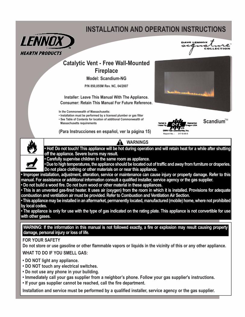
INSTALLATION AND OPERATION INSTRUCTIONS Catalytic Vent - Free Wall-Mounted Fireplace Model: Scandium-NG P/N 850,055M Rev. NC, 04/2007 Installer: Leave This Manual With The Appliance. Consumer: Retain This Manual For Future Reference. In the Commonwealth of Massachusetts: • Installation must be performed by a licensed plumber or gas fitter • See Table of Contents for location of additional Commonwealth of Massachusetts requirements (Para Instrucciones en español, ver la página 15) FOR YOUR SAFETY Do not store or use gasoline or other flammable vapors or liquids in the vicinity of this or any other appliance. WHAT TO DO IF YOU SMELL GAS: • DO NOT light any appliance. • DO NOT touch any electrical switches. • Do not use any phone in your building. • Immediately call your gas supplier from a neighbor’s phone. Follow your gas supplier's instructions. • If your gas supplier cannot be reached, call the fire department. Installation and service must be performed by a qualified installer, service agency or the gas supplier. • Hot! Do not touch! This appliance will be hot during operation and will retain heat for a while after shutting off the appliance. Severe burns may result. • Carefully supervise children in the same room as appliance. • Due to high temperatures, the appliance should be located out of traffic and away from furniture or draperies. Do not place clothing or other materials on or near this appliance. • Improper installation, adjustment, alteration, service or maintenance can cause injury or property damage. Refer to this manual. For assistance or additional information consult a qualified installer, service agency or the gas supplier. • Do not build a wood fire. Do not burn wood or other material in these appliances. • This is an unvented gas-fired heater. It uses air (oxygen) from the room in which it is installed. Provisions for adequate combustion and ventilation air must be provided. Refer to Combustion and Ventilation Air Section. • This appliance may be installed in an aftermarket, permanently located, manufactured (mobile) home, where not prohibited by local codes. • The appliance is only for use with the type of gas indicated on the rating plate. This appliance is not convertible for use with other gases. Scandium WARNINGS TM WARNING: If the information in this manual is not followed exactly, a fire or explosion may result causing property damage, personal injury or loss of life. 317-S-05-5 Report No. :
Transcript of Catalytic Vent - Free Wall-Mounted Fireplace - Wittus · Catalytic Vent - Free Wall-Mounted...
INSTALLATION AND OPERATION INSTRUCTIONS
Catalytic Vent - Free Wall-MountedFireplace
Model: Scandium-NG P/N 850,055M Rev. NC, 04/2007
Installer: Leave This Manual With The Appliance.Consumer: Retain This Manual For Future Reference.
In the Commonwealth of Massachusetts:• Installation must be performed by a licensed plumber or gas fitter• See Table of Contents for location of additional Commonwealth of
Massachusetts requirements
(Para Instrucciones en español, ver la página 15)
FOR YOUR SAFETYDo not store or use gasoline or other flammable vapors or liquids in the vicinity of this or any other appliance.WHAT TO DO IF YOU SMELL GAS:• DO NOT light any appliance.• DO NOT touch any electrical switches.• Do not use any phone in your building.• Immediately call your gas supplier from a neighbor’s phone. Follow your gas supplier's instructions.• If your gas supplier cannot be reached, call the fire department.Installation and service must be performed by a qualified installer, service agency or the gas supplier.
• Hot! Do not touch! This appliance will be hot during operation and will retain heat for a while after shuttingoff the appliance. Severe burns may result.• Carefully supervise children in the same room as appliance.• Due to high temperatures, the appliance should be located out of traffic and away from furniture or draperies.Do not place clothing or other materials on or near this appliance.
• Improper installation, adjustment, alteration, service or maintenance can cause injury or property damage. Refer to thismanual. For assistance or additional information consult a qualified installer, service agency or the gas supplier.• Do not build a wood fire. Do not burn wood or other material in these appliances.• This is an unvented gas-fired heater. It uses air (oxygen) from the room in which it is installed. Provisions for adequatecombustion and ventilation air must be provided. Refer to Combustion and Ventilation Air Section.• This appliance may be installed in an aftermarket, permanently located, manufactured (mobile) home, where not prohibitedby local codes.• The appliance is only for use with the type of gas indicated on the rating plate. This appliance is not convertible for usewith other gases.
Scandium
WARNINGS
TM
WARNING: If the information in this manual is not followed exactly, a fire or explosion may result causing propertydamage, personal injury or loss of life.
317-S-05-5 Report No. :

2
This appliance is a high efficiency, unvented, flame effect gas heater. Itprovides radiant and convected warmth both efficiently and safelyutilizing the latest type catalytic convertor burner technology. Theappliance does not require a flue system of any type as the catalyticconverter cleans the flue products to provide a complete combustionsystem, which is intrinsically safe.
These heaters are fitted with a specially designed pilot utilizing anoxygen depletion sensor (ODS) which responds to the amount ofoxygen available in the room and shuts the heater off before the oxygenlevel drops below 18%. The pilot can be relit only when fresh air isavailable. Refer to the Combustion and Ventilation Air section.
The appliance is designed to fit various types of situations as listed inthe Installation Requirements.
This appliance is factory set for operation on the gas type, and at thepressure stated on the appliance rating plate.
On first light up of a new appliance, initial curing of high temperaturepaint and burning off of lubricants may occur for the first few hours ofoperation. During this period some smoke may be emitted from outletgrille, this should be no cause for concern. Accordingly, the roomshould be well ventilated with all windows and doors open during thisperiod.
Read all these instructions before commencing installation. Allinstructions must be handed to the user for safekeeping.
QUANTITY DESCRIPTION1 Firebox and burner assembly1 Installation and operating instructions1 Glass facia panel assembly 1 Fitting template1 Screw and wall plug pack1 Rubber grommet
Section Contents Page No.1.0 General Information 22.0 Packaging List 23.0 Appliance Data 24.0 Important Safety Information 25.0 Codes 46.0 Combustion and Ventilation Air 47.0 Site Requirements 48.0 Preparing the Appliance 59.0 Mounting the Appliance 510.0 Checking the Burner 611.0 Connecting a Gas Line 612.0 Checking the Gas Connections 713.0 Gas Pressure Check 714.0 Spark Gap 715.0 Assembly of the Glass Facia 716.0 Fitting the Glass Facia 817.0 Fitting the side panels 818.0 Briefing the customer 919.0 Servicing 920.0 Servicing the Burner 921.0 Pilot Assembly 1022.0 Catalysts 1023.0 Testing for Firebox Leakage 1024.0 Cleaning 1025.0 Lighting Instructions 1126.0 To Turn off gas to Appliance 1127.0 Troubleshooting Guide 1228.0 Replacement Parts 1229.0 Positioning of field assembled parts 13
1.0 GENERAL INFORMATION
2.0 PACKAGING LIST
4.0 IMPORTANT SAFETY INFORMATION
TABLE OF CONTENTS
3.0 APPLIANCE DATAGas Type Natural GasGas inlet pressure Maximum 10.5” w.c.
Minimum 6” w.c.Regulator Pressure Setting 5” w.c.Max Energy Input 11,950 BTU/hrMin Energy Input 6,820 BTU/hrPilot Energy Input 560 BTU/hourBurner (Manifold) Pressure High 2.4” w.c.
Low 0.8” w.c. Main burner flow restrictor 2.0mm (0.079”) Oxypilot SIT/Bray 9082Gas Inlet Connection 3/8” NPT at regulatorIgnition Piezo sparkSpark Gap 1/8” - 3/16”Please see Data Plate affixed to appliance for current data.This appliance is for use only with the gas type, and at the pressurestated on the appliance Data Plate.
T H E F O L L O W I N G B O X E D I N F O R M AT I O N A P P L I E S T OREQUIREMENTS FOR THE COMMONWEALTH OF MASSACHUSETTS.Note: The following requirements reference various Massachusetts andnational codes not contained in this document.
Unvented Room Heaters shall be installed in accordance with 527 CMR30.00 and 248 CMR 3.00 through 7.00:
(a) Permits and Inspections: In addition to complying with 248 CMR 3.05the following requirements must be satisfied:
1. A permit shall be obtained from the head of the fire department and thelocal or state gas inspector having jurisdiction for the installation of allunvented propane or natural gas-fired space/room heaters.
2. The permits shall be conditioned upon final inspection and approval ofinstallation by the head of the fire department and the local or state gasinspector having jurisdiction.
3. A copy of the manufacturer’s installation/operating literature shall besubmitted with each permit application.
4. Before operation, the Head of the Fire Department and the local or stategas inspector shall inspect the installation for compliance with 527 CMR(Board of Fire Prevention Regulations) and 248 CMR (Board of StateExaminers of Plumbers and Gas Fitters).
READ AND UNDERSTAND THESE INSTRUCTIONSCOMPLETELY BEFORE INSTALLING OR OPERATINGYOUR UNVENTED ROOM HEATER.
IMPORTANT

• Children and adults should be alerted to the hazard of high surfacetemperature and should stay away to avoid burns or clothing ignition.
• Young children should be carefully supervised when they are in thesame room with the heater.
• Do not place clothing or other flammable material on or near theheater.
• Any safety screen or guard removed for servicing the heater must bereplaced prior to operating the heater.
• Installation and repair should be done by a qualified service person.The heater should be inspected before use and at least annually by aprofessional service person. More frequent cleaning may be requireddue to excessive lint from carpeting, bedding material, etc. It isimportant that control compartments, burners and circulating airpassageways of the heater be kept clean.
• Allow the heater to cool before servicing. Always shut off the gas tothe heater while performing service work.
• The installation must conform with local codes or, in the absence oflocal codes with the National Fuel Gas Code, ANSI Z223.1.
• The heater and its individual shut-off valve must be disconnectedfrom the gas supply piping system while performing any tests of thegas supply piping system at pressures in excess of 1/2 psig.
• The heater must be isolated from the gas supply piping system byclosing its individual manual shut-off valve during any pressuretesting of the gas supply piping system at test pressures equal to orless than 1/2 psig.
• Keep heater area clear and free from combustible materials, gasolineand other flammable vapors and liquids.
• Do not use this heater if any part has been under water. Immediatelycall a qualified service technician to inspect the room heater and toreplace any part of the control system and any gas control which hasbeen under water.
• Input ratings are shown in BTU per hour and are for elevations up to4,500 feet. If these appliances are installed at elevations above 4,500feet, nuisance pilot outages may occur. Do not install this heater at anelevation above 4,500 feet if the gas supply has not been derated forthat elevation. Consult your local gas supplier.
• Ensure that the heater is clean when operating. Excessive dustaccumulation on the burner will increase the amount of carbonmonoxide formation and could lead to carbon monoxide poisoningand/or death.
• Vent-free gas fireplaces are designed for use as a supplementalheaters. They are not intended for continuous use as a primarysource.
3
4.0 IMPORTANT SAFETY INFORMATION (continued)
5. A final inspection by the state or local gas inspector of the unventedspace/room heater shall not be performed until proof is provided that thehead of the fire department having jurisdiction has granted a permit.
(b) Unvented natural gas-fired space/room heaters shall conform to ANSIZ21.11.2, be equipped with an oxygen depletion safety (ODS) shutoffsystem and be Product-approved in accordance with 248 CMR.
(c) Unvented natural gas-fired space/room heaters shall be installed inaccordance with their listings and the manufacturer’s instructions. Properclearances to combustibles shall be maintained. In no case shall theclearances be such as to interfere with combustion air and accessibility.
(d) Installations shall be of a permanent type, with a permanently pipedfuel supply in accordance with 248 CMR. LPG appliances shall be subjectto the storage requirements in accordance with 527 CMR 6.00. Portableunvented or natural gas-fired space/room heaters shall be prohibited.
(e) Unvented natural gas-fired space/room heaters shall be prohibited inbedrooms and bathrooms.
(f) Space/room heaters shall be properly sized for the room or space ofinstallation, but shall not exceed a maximum of 40,000 BTU input per roomor space.
(g) In occupancies with an unvented natural gas-fired space/room heater,no less than one listed carbon monoxide detector that is installed inaccordance with the manufacturers instructions shall be installed andmaintained near the space where the heater is located.
1. Any building wherein the heater is to be installed shall, as a preconditionto such installation, have working smoke detectors installed andmaintained in accordance with the requirements of 780 CMR (State Boardof Building Regulations and Standards) in effect at the time of constructionor;
2. If no requirement was in effect at the time of construction the smokedetector shall be compliant and installed as provided for in M.G.L. c. 148,§ 26E.
(h) In rooms and buildings served by an unvented natural gas-firedspace/room heater, a primary source of heat, which is operable, shall bepermanently installed and maintained in the building in accordance with105 CMR (Department of Public Health).
(i) Sellers of unvented natural gas-fired space/room heaters shall provideto each purchaser a copy of 527 CMR 30.00 upon sale of the unit.
• Installation and repair must be done by a plumber or gas fitter licensedin the Commonwealth of Massachusetts.
• The flexible gas line connector used shall not exceed 36 inches (92centimeters) in length.
•The individual manual shut-off must be a T-handle type valve.
FAILURE TO KEEP THE PRIMARY AIR OPENING(S) OF THEBURNER(S) CLEAN MAY RESULT IN SOOTING ANDPROPERTY DAMAGE.
WARNING
T H E F O L L O W I N G B O X E D I N F O R M AT I O N A P P L I E S T OREQUIREMENTS FOR THE COMMONWEALTH OF MASSACHUSETTS.
New York : This appliance is approved for installation in the U.S. stateof New York, but not New York City.
FAILURE TO COMPLY WITH THE INSTALLATION ANDOPERATING INSTRUCTIONS PROVIDED IN THISDOCUMENT WILL RESULT IN AN IMPROPERLY INSTALLEDAND OPERATING APPLIANCE, VOIDING ITS WARRANTY.ANY CHANGE TO THIS APPLIANCE AND/OR ITSOPERATING CONTROLS IS DANGEROUS. IMPROPERINSTALLATION OR USE OF THIS APPLIANCE CAN CAUSESERIOUS INJURY OR DEATH FROM FIRE, BURNS,EXPLOSION OR CARBON MONOXIDE POISONING.
WARNING
CHECK GAS TYPE : THE GAS SUPPLY MUST BE THE SAMEAS STATED ON THE APPLIANCE’S RATING PLATE. IF THEGAS SUPPLY IS DIFFERENT DO NOT INSTALL THEAPPLIANCE. CONTACT YOUR DEALER FOR THE CORRECTMODEL.
WARNING
Example:Vent-free heater #1 9,000 BTU/HrVent-free heater #2 23,000 BTU/HrGas appliance #1 35,000 BTU/Hr(water heater)
Total = 67,000 BTU/Hr* Do not include direct-vent gas appliances. Direct-vent is sealedcombustion and draws combustion air from the outdoors.
The space in the previous example is a confined space because the actualBTU/Hr used is more than the maximum BTU/Hr the space can support.You must provide additional fresh air. Your options are:a. Rework equations adding the space of adjoining room(s). If the extravolume provides an unconfined space, then remove door or add ventilationgrills between rooms. Refer to National Fuel Gas Code, ANSI Z223.1,Section 5.3.b. Vent room directly to the outdoors. Refer to National Fuel Gas Code,ANSI Z223.1, Section 5.3.c. Install a lower BTU/Hr heater, to make the area an unconfined space.If the actual BTU/Hr used is less than the maximum BTU/Hr the space cansupport, then the space is an unconfined space. You will need no additionalfresh air ventilation for an unconfined space.
This appliance is designed to be wall-hung. Do not recess any part ofthe appliance into the wall. This appliance may be installed in anyroom in a home except bedrooms or bathrooms - or areas where largeamounts of steam are likely to be generated.
It should be noted that heaters create warm air currents. Thesecurrents move heat to wall surfaces next to the heater. Installingthe heater next to vinyl or cloth wall coverings or operating theheater where impurities in the air (such as tobacco smoke orcandle smoke) exist, may discolour walls.
Installation in living rooms is common, however other rooms such askitchens, dining rooms and hallways are permitted, providing a suitablenatural gas supply is available, and rooms sizing and ventilationrequirements are strictly adhered to (see section 4).
The appliance is designed to be versatile, and as such will operate correctlywhen exposed to normal gentle drafts experienced within the home. It is notrecommended, however that the appliance be installed in areas where it islikely to be exposed to persistent strong drafts, that may be generated byoutside doors or windows, air vents etc. It is recommended that theappliance should not be installed within 20” of any air vent.
4
5.0 CODESAdhere to all local codes or in their absence the latest edition of TheNational Fuel Gas Code ANSI Z223.1 or NFPA54 which can be obtainedfrom The American National Standards Institute, Inc. (1430 Broadway, NewYork, NY, 10018) or National Fire Protection Association, Inc. (BatterymarchPark, Quincy, MA, 02269).
Seller of unvented natural gas fired supplemental room heaters in thecommonwealth of Massachusettes shall provide to each purchaser a copyof 527 CMR 30 upon sale of the unit. Please refer to section 4.0 on page 2of this manual.
This Lennox Hearth Products unvented gas room heater is certified byOMNI-Test Laboratories, Inc to ANSI Z21.11.2-2007 standard.
This heater shall not be installed in a confined space or unusually tightconstruction unless provisions are provided for adequate combustion andventilation air.
The National Fuel Gas Code, ANSI Z223.1/NFPA 54 defines a confinedspace as a space whose volume is less than 50 ft 3 per 1,000 BTU/Hr (4.8m3 per kW) of the aggregate input rating of all appliances installed in thatspace and an unconfined space as a space whose volume is not less than50 ft 3 per 1,000 BTU/Hr (4.8 m3 per kW) of the aggregate input rating of allappliances installed in that space.
Rooms communicating directly with the space in which the appliances areinstalled, through openings not furnished with doors, are considered a partof the unconfined space.Unusually tight construction is defined as construction where:
a. wall and ceilings exposed to the outside atmosphere have a continuouswater vapor retarder with a rating of one perm or less with openingsgasketed or sealed, and
b. weather stripping has been added on operable windows and doors, and
c. caulking or sealants are applied to areas such as joints around windowand door frames, between sole plates and floors, between wallceiling joints,between wall panels, at penetrations for plumbing, electrical, and gas lines,and at other openings.Use the following equations to determine if you have a confined orunconfined space.
Determine the volume of space — ft 3.
Length x Width x Height = _____ ft 3
(Include adjoining rooms with doorless passageways or ventilationgrills between rooms.)
Example: 24' (L) x 16' (W) x 8' (H) = 3072 ft 3
Divide the volume of space by 50 ft 3 to determine the maximumBTU/Hr the space can support.
______ (volume of space – ft 3)/ 50 ft 3 =(Maximum BTU/Hr the space can support)
Example: 3072 ft 3 / 50 ft 3 = 61.44or 61,440 BTU/Hr the space can support.
Add the BTU/Hr of all the fuel burning appliances in the space.
Vent-Free heater _______ BTU/HrGas appliance #1* _______ BTU/HrGas appliance #2 + _______ BTU/HrGas appliance #3 + _______ BTU/Hr
Total = _______ BTU/Hr
1.
2.
3.
6.0 COMBUSTION AND VENTILATION AIR
4. Compare the maximum BTU/Hr the space can support with theactual amount of BTU/Hr used.
_______ BTU/Hr (max. the space can support)_______ BTU/Hr (actual amount of BTU/Hr used)
Example:61,440 BTU/Hr (max. the space can support)67,000 BTU/Hr (actual amount of BTU/Hr used)
7.0 SITE REQUIREMENTS
IF THE AREA IN WHICH THE HEATER MAY BE OPERATED ISSMALLER THAN THAT DEFINED AS AN UNCONFINEDSPACE OR IF THE BUILDING IS OF UNUSUALLY TIGHTCONSTRUCTION, PROVIDE ADEQUATE COMBUSTION ANDVENTILATION AIR BY ONE OF THE METHODS DESCRIBEDIN THE NATIONAL FUEL GAS CODE, ANSI Z223.1/NFPA 54,SECTION 5.3 OR APPLICABLE LOCAL CODES.
WARNING

Clearances to non-combustiblesNon-combustible surfaces are defined as brick, metal, marble, concreteetc. and also a number of man-made materials impervious to flame. If indoubt refer to the material manufacturer for further information beforeproceeding with installation.
Clearances to the sides of the appliance are 4”. Clearance to the front ofthe appliance is 20”.
The back of the appliance may be installed directly onto a non-combustiblewall, providing the area behind the appliance is flat and does not interferewith the various vent holes in the back panel of the appliance.
The appliance may be installed with or without a non-combustible hearth. Ifa hearth is fitted, the size and design may be as desired.
A non-combustible shelf of any depth may be positioned above theappliance provided it is no closer than 16” from the top of the applianceglass panel and the wall above the appliance is non combustible.
Clearances to combustible materialsCombustible materials are defined as wood, fabrics, or other materialslikely to combust if exposed to flame. Generally, any material, which is likelyto discolour, melt or misshape when exposed to moderate heat, should beconsidered as a combustible material or surface.
Clearance to the sides of the appliance are 4” but curtains, drapes andother fabrics are not permitted within a distance of 20” of the appliancesides. No such materials are permitted directly above the applianceregardless of distance.
The minimum clearance to the ceiling above the appliance is 32” measuredfrom the top of the appliance glass panel.
Combustible materials should not be positioned directly in front of theappliance within a distance of 40”.
Under no circumstances should any electrical equipment e.g. plasmascreen TV sets etc. be positioned on the wall above the appliance. Theappliance is designed to be wall mounted alone and not in conjunction withany type of combustible fire surround.
No combustible shelves should be positioned on the wall above theappliance.
It should be established that any mirrors or picture frames etc. to bepositioned on the wall above the appliance are able to withstand prolongedexposure to moderate heat and moisture before proceeding with theirinstallation.
The back of the appliance may be installed directly onto a combustible wall,providing it is flat and does not interfere with the various vent holes in theback panel of the appliance. The wall must be structurally sound andconstructed from a material capable of withstanding moderate heat.Finished plaster, conventional wall paper and dry-lined plasterboard areexamples of suitable materials. Materials such as flock, blown vinyl andembossed paper which are sensitive to even small amounts of heat shouldbe avoided as scorching and or discoloration may occur over time.
If the appliance is to be mounted on a dry-lined wall or a timber framedconstruction wall then the integrity and ability of the wall to carry the weightof the appliance must be confirmed. It is important in these circumstancesthat any vapor control barrier is not damaged, and that any structuralmembers of the house frame are not damaged.
The appliance may be positioned as close to a solid floor (i.e. stone,wooden laminate etc.) as the particular design of fire frame permits,however it is not permitted to install the appliance within 4” of carpet, rugsor fabric materials of any kind. This dimension is measured vertically to thebottom of the appliance frame.
Gas connection :The heater gas inlet connection is 3/8” NPT at theregulator, located below the burner, in the center of the heater.
There are four possibleentry points for the gassupply pipework to enterthe appliance firebox.These entry points are‘knock out’ type holes(shown in figure 1).Non-concealed gasconnections may bemade using the entrypoints on the base of thefirebox. A concealedgas connection may bemade using the knockout hole in the centreback of the firebox.Select the mostappropriate entry point and knock out the relevant hole. If a concealed gas connection is to be made, the supply pipe should alwaysbe sleeved through walls and floors using the shortest possible route.
For concealed supply pipe routing, pipes must (where possible) be verticaland providing there is sufficient wall thickness available, they should beplaced in pipe chases. Horizontal pipe runs should be avoided wherepossible. Prior to chasing a solid wall, an inspection should be made to notethe proximity of any cables/sockets outlets which may already be buried.Pipes must be secured using suitable clips and protected against corrosion.Ideally factory finished protected pipework and fittings should be used.Joints should be kept to a minimum and compression fittings must not beused. The pipework installation must be tested for soundness before anyprotection is applied and/or the pipework and fittings are buried.
After having selected the final mounting position of the appliance, takinginto account the site requirements as specified in section 7 of theseinstructions, the integrity of the wall, and the feasibility of the proposedsupply pipe routing, the firebox of appliance may be secured to the wall.
5
7.0 SITE REQUIREMENTS (continued)
8.0 PREPARING THE APPLIANCE
9.0 MOUNTING THE APPLIANCE
Figure 1
DO NOT USE A BLOWER INSERT, HEAT EXCHANGERINSERT OR OTHER ACCESSORY NOT APPROVED FORUSE WITH THIS HEATER.
WARNING
DO NOT ALLOW ANY FANS TO BLOW DIRECTLY INTOTHE FIREPLACE. AVOID ANY DRAFTS THAT ALTERBURNER FLAME PATTERNS.
WARNING

There are no imitation fuel bed components to install. The appliancefeatures a ribbon burner which is designed to produce a continuousband of flame over its length. The burner should be visually inspectedto ensure it is free from any foreign matter. If it is necessary to clean ordust off the burner then the glass door should be removed by removalof the four retaining screws. Re-fit the glass door after cleaning orinspection, ensuring a good seal.
A qualified gas appliance installer must connect the gas room heater tothe gas supply. Consult all local codes. The installer must provide anANSI approved manual shut off valve, flex connector and 3/8" NPTfitting. Route gas line using techniques and materials prescribed by localand/or national codes. Only use pipe of 1/2"or greater size to allow fullgas volume to the gas fireplace. Undue pressure loss will occur if thepipe is too small. An ANSI approved manual shut-off valve and unionmust be installed upstream of the heater within the fireplace cavitywhen rigid pipe is used. Ensure that a sediment trap is installedupstream of the heater (figure 4) within the structure’s piping system toprevent moisture and contaminants from passing through the pipe tothe heater controls and burner. Failure to do so could prevent the heaterfrom operating reliably. The heater gas inlet connection is 3/8” NPT atthe regulator, located below the burner, in the right hand side of theheater. When tightening up the joint to the regulator hold the regulatorsecurely with a wrench to prevent the regulator from moving.
6
To ensure customer safety, be sure to design the installation so that thestrength of both the wall and any wall fixings used are sufficient. LennoxHearth Products assumes absolutely no responsibility for injuries anddamages that may occur due to improper installation or handling.
The appliance should not be installed until all dry wall sanding and wallpainting has been completed.Incorrect installation can cause the appliance to fall from the wall andcause injury. Do not block the ventilation holes of the appliance. Thewall onto which the appliance is installed must be flat. Install only on avertical surface. Avoid sloped surfaces. Installation onto anything otherthan a vertical wall may result in fire, damage or injury.
A full size fitting template is supplied to assist with wall mounting.
Mark the positions shown as “Fixing Points” on the wall. If the applianceis to be mounted on the inner leaf of a conventional cavity wall, or asolid wall, drill four holes using a 1/4” masonry bit. Insert the fiber wallplugs provided.
If the appliance is to be mounted on a dry lined wall or a timber framedconstruction wall then special cavity screw fixings will be required whichare not supplied with this product. These should be constructed frommetal and not plastic.
If a concealed gas connection is to be made ensure the gas supply pipeis in it’s final position and can enter the appliance in the correct positionwhen the appliance is hung on the wall.Insert the wall mounting screws into the top wall plugs, taking care toleave the screws protruding approximately 3/8” from the wall. Now hangthe appliance onto these screws through the two keyhole shaped holesin the back panel of the appliance. Insert the lower mounting screws into the lower wall plugs through thecorresponding depressed holes in the lower part of the back panel. Donot tighten fully.
Before tightening the wall mounting screws fully, at this stage it isrecommended to check the horizontal alignment of the appliance with aspirit level, as small adjustments can still be made if necessary. Whenthis has been checked, tighten all four fixing screws fully. To access the upper fixing screws insert a screwdriver through theholes in the deflector plates above the catalyst as shown in figure 3.
Figure 2
Figure 3
11.0 CONNECTING A GAS LINE
9.0 MOUNTING THE APPLIANCE (continued)
Figure 4
10.0 CHECKING THE BURNER
THE WALL WHERE THE APPLIANCE IS TO BEINSTALLED MUST BE CAPABLE OF LONG-TERMSUPPORT OF THE TOTAL LOAD OF THE APPLIANCE.MEASURES SHOULD ALSO BE TAKEN TO ENSURESUFFICIENT STRENGTH TO WITHSTAND THE FORCE OFEARTHQUAKES, VIBRATION AND OTHER EXTERNALFORCES.
WARNING
HOLD HEATER REGULATOR WITH A WRENCH TOPREVENT MOVEMENT WHEN CONNECTING TO INLETPIPING.
IMPORTANT
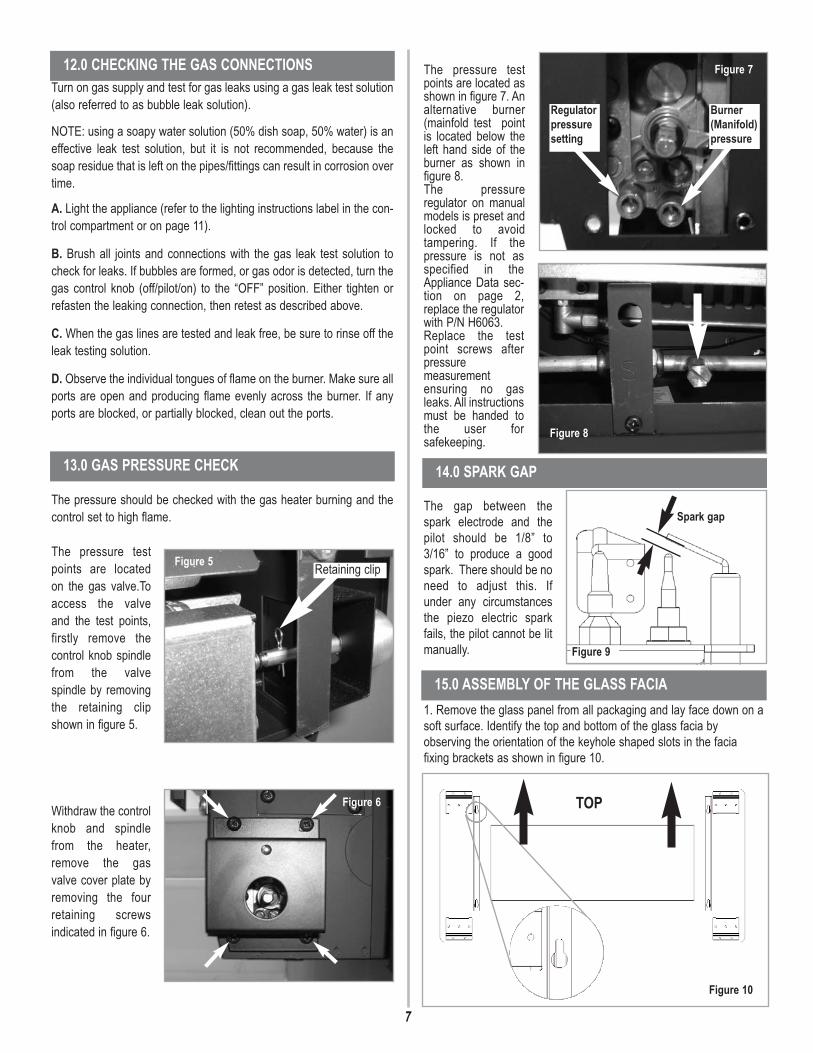
The pressure testpoints are located asshown in figure 7. Analternative burner(mainfold test pointis located below theleft hand side of theburner as shown infigure 8. The pressureregulator on manualmodels is preset andlocked to avoidtampering. If thepressure is not asspecified in theAppliance Data sec-tion on page 2,replace the regulatorwith P/N H6063. Replace the testpoint screws afterpressuremeasurementensuring no gasleaks. All instructionsmust be handed tothe user forsafekeeping.
The gap between thespark electrode and thepilot should be 1/8” to3/16” to produce a goodspark. There should be noneed to adjust this. Ifunder any circumstancesthe piezo electric sparkfails, the pilot cannot be litmanually.
1. Remove the glass panel from all packaging and lay face down on asoft surface. Identify the top and bottom of the glass facia byobserving the orientation of the keyhole shaped slots in the faciafixing brackets as shown in figure 10.
7
Turn on gas supply and test for gas leaks using a gas leak test solution(also referred to as bubble leak solution).
NOTE: using a soapy water solution (50% dish soap, 50% water) is aneffective leak test solution, but it is not recommended, because thesoap residue that is left on the pipes/fittings can result in corrosion overtime.
A. Light the appliance (refer to the lighting instructions label in the con-trol compartment or on page 11).
B. Brush all joints and connections with the gas leak test solution tocheck for leaks. If bubbles are formed, or gas odor is detected, turn thegas control knob (off/pilot/on) to the “OFF” position. Either tighten orrefasten the leaking connection, then retest as described above.
C. When the gas lines are tested and leak free, be sure to rinse off theleak testing solution.
D. Observe the individual tongues of flame on the burner. Make sure allports are open and producing flame evenly across the burner. If anyports are blocked, or partially blocked, clean out the ports.
The pressure should be checked with the gas heater burning and thecontrol set to high flame.
The pressure testpoints are locatedon the gas valve.Toaccess the valveand the test points,firstly remove thecontrol knob spindlefrom the valvespindle by removingthe retaining clipshown in figure 5.
Withdraw the controlknob and spindlefrom the heater,remove the gasvalve cover plate byremoving the fourretaining screwsindicated in figure 6.
12.0 CHECKING THE GAS CONNECTIONS
13.0 GAS PRESSURE CHECK
Figure 5 Retaining clip
Figure 6
Burner(Manifold)pressure
Regulatorpressuresetting
Figure 7
Figure 8
14.0 SPARK GAP
Figure 9
Spark gap
TOP
Figure 10
15.0 ASSEMBLY OF THE GLASS FACIA

8
2. Slide on the side pieces ensuring that the grille fixing holes (shown)are aligned towards the top of the glass facia (as shown in figure 11).
3.Ensure the sides are neatly aligned with the glass and secure thesides using two M6 screws for each side as shown in figure 12. Donot overtighten the screws.
4. Position the grille within the two side pieces ensuring a neat fit.
5. Secure the grille in position using two M6 screws and two no. 8 selftapping screws as shown in figure 14.
The glass facia panel is supported by four M6 screws which protrudefrom the front of the outer casing. Insert the M6 retaining screws andensure they are unscrewed approximately 1/8” so the keyhole shapedholes may engage, and the facia can be hooked on. Ensuring that thecorresponding keyhole shaped holes engage the screwheads fully.Refer to figure 15.
Remove the two side panel
assemblies from the protective
packaging and fit onto the sides of the
firebox as shown. Insert the M6
retaining screws in the sides of the
firebox and ensure they are
unscrewed approximately 1/8” so the
keyhole shaped holes may engage,
and the sides can be hooked on.
16.0 FITTING THE GLASS FACIA15.0 ASSEMBLY OF THE GLASS FACIA - (continued)
Grille fixing holes
Figure 11
Figure 12
TOP
Figure 13
Figure 14
Figure 15
17.0 FITTING THE SIDE PANELS
Note : Front frame/facia not shownfor clarity.
Figure 16

9
Insert a screwdriverthrough the holes in theright hand side panel toaccess the two M6 fixingscrews (designated ‘a’ infigure 17) and tighten fully.Next insert two no.8 selftapping screws (designated‘b’ in figure 17) through theside panel support bracket,and the correspondingholes in the side of thefirebox. Tighten fully.
Repeat for the left handside panel, which issecured by tightening theM6 ‘a’ screws only.
The right-hand side panelhas a hinged flap to allowaccess to the control knob.
After commissioning the appliance, the customer should be instructedon the safe use of the appliance and the need for regular servicing.Frequency of service depends on usage, but MUST be carried out atleast once annually.
Advise that cleaning of the fireplace may be achieved when thefireplace is cold using a damp cloth and mild detergent on mostsurfaces.
Advise that the fireplace will emit an odor for a time after initialcommissioning and that extra ventilation may be needed during thistime. A periodic visual check of the pilot flame and the burner flameshould be carried out. (Refer to figure 22).
A suggested procedure for servicing is detailed as follows;
Turn off the fireplace at the the gas supply. Ensure that the fireplace isfully cold before attempting service.
1. Lay out the dustsheet and tools.2. Remove the front glass facia as described in section 16.0,
only in reverse.3. Remove the glass door assembly (5 screws) and clean
carefully. Remove the valve cover plate (4 screws).
4. Inspect the burner and the catalysts and clean if necessarywith a soft brush.
5. Disconnect the gas supply.6. Undo the four screws retaining the burner support brackets to
the base and rear of the firebox. 7. Remove the burner unit, strip off the burner pipes and clean
thoroughly.8. Clean the in-line restrictor, pilot assembly and the burner
tube. Do not attempt to remove the pilot injector as this cancause damage.
9. Re-assemble components.10. Turn on the gas supply and leak test. Check pilot and
burner for good ignition.11. Refit the valve cover and retaining screws.12. Refit the glass door assembly.13. Refit the facia Refitting as described in section 15.0.14. Check the purpose provided ventilation is unobstructed. 15. Light the fire and test setting pressures.16. Check safe operation of the appliance. For specific servicing instructions, see relevant sections.
First, remove the front Glass facia as described in Section 16.0 only inreverse, remove the valve cover (4 screws) and disconnect the gasconnection inside appliance. The gas connections to the gas valve cannow be released. Undo the four screws retaining the burner brackets tothe base and rear of the firebox. The burner may now be removed.
Remove the pilot and main burner pipes and blow through to dislodgeany debris. Now remove the in line restrictor and blow through to makesure it is entirely clear.
Unclip the pilot lint gauze and clean with a soft brush. Clean the exteriorof the pilot assembly with a soft brush and blow through the flame portson the pilot head. Check the aeration holes are free from lint or dirt. Thepilot assembly can be removed if required by disconnecting theelectrode HT lead, gas pipe, thermocouple lead and unscrewing themounting screws and lifting away. The pilot assembly is a non-serviceable item and should not be taken apart. Aeration holes must beabsolutely clear internally for proper operation. NEVER MODIFY ORBEND THE THERMOCOUPLE TO MAKE THE PILOT STAY ALIGHT.Modifications are dangerous and can have serious unseen effects onsafety. If the pilot will not stay lit there is a problem with dirt, the gassupply to it, or the thermocouple needs replacement. The gas valve is a non-serviceable item. If this needs replacement,remove the cover plate then the securing screw holding the valvebracket in place, remove all pipe unions, and the complete valve.Replacement must be original manufacturers parts.Re-assemble in the reverse of removal. Ensure setting pressures areas stated in Section 3; Appliance Data.
17.0 FITTING THE SIDE PANELS (continued)
19.0 SERVICING
20.0 SERVICING THE BURNER
‘a’
‘a’
‘b’‘b’
Figure 17
18.0 BRIEFING THE CUSTOMER
DO NOT ADD LOGS OR ORNAMENTS SUCH AS PINECONES, VERMICULITE OR ROCK WOOL. USINGTHESE ADDED ITEMS CAN CAUSE SOOTING.
WARNING ANY CHANGE TO THIS HEATER OR ITS CONTROLSCAN BE DANGEROUS.
WARNING

Remove the glass facia, glass panel and burner unit (as per servicingsection), lint arrestor and pilot unit by using a screwdriver to remove theretaining screws. Clean the pilot assembly with a soft brush and blowthrough. Check the aeration holes are free of any dirt or lint. Cleanthoroughly internally, the connection can be removed from the base ofthe pilot unit using two spanners to make cleaning easier. Do notdamage or try to dismantle the pilot injector. The unit is factory set andthe only check necessary is to ensure the spark gap is correct. Seespecifications for gas setting.NEVER MODIFY OR BEND THE THERMOCOUPLE TO MAKE THEPILOT STAY ALIGHT. If the pilot will not stay lit there is a problem withdirt, the gas supply, or the thermocouple needs replacement.Modifications are dangerous and can have a serious unseen effect onsafety and therefore MUST not be done. Replacements must be origi-nal manufacturers parts. Re-assemble in the reverse of removal.Ensure setting pressures are as stated in Section 3; Appliance Data.It is recommended that the catalysts are inspected for signs of damageand dirt during routine servicing procedures. The expected life of the
catalysts is in excess of 11,000 hours (10 years of normal use). Afterthis time the catalyst should be replaced. If there are any deposits of dirtor soot on the catalysts they should be cleaned with a soft brush and avacuum cleaner. If removed for cleaning ensure the seals are in goodcondition before replacing the catalyst. New seals will usually berequired.The performance of the catalyst may be checked using a combustiongas analyzer as follows. Important: The temperature of the gases
emitted by the catalytic converters is in excess of 700 oF. Measuring gasof this temperature may damage some types of gas analyzers. If indoubt consult the equipment manufacturer.Turn on the fireplace as per the operating instructions, and run atmaximum setting for 15 minutes. Position gas sample probe directlyover a catalyst via the outlet grille, on top of the appliance. Record thecarbon dioxide (CO2) concentration and then the carbon monoxide(CO) concentration as displayed by the analyzer - also noting the unitsin which the values are expressed. Most analyzers display carbondioxide (CO2) concentrations in percentage (%) terms and carbonmonoxide concentration in parts per million (ppm) terms.In order to calculate the combustion ratio for the appliance (CO/CO2) itis first necessary to express both gas concentrations in terms of per-centage. To convert from parts per million (ppm) to a percentage (%)divide the ppm figure by 10,000. Examples : 35ppm = 0.0035%, 15ppm= 0.0015%, 5ppm = 0.0005%.Now divide the concentration of carbon monoxide (CO) expressed inpercent by the concentration of carbon dioxide (CO2) to obtain theappliance combustion ratio.
The combustion ratio of the gasses emitted by the catalytic convertorshould not exceed 0.0015. If replacing, firstly, remove the glass facia asdescribed in section 15.0. The catalysts are located on the top of theinternal firebox and can be removed be unscrewing the retaining nutssecuring the clamping plate. Remove the catalysts and seals anddiscard. Refit a new catalysts and seals in reverse order, ensure thecatalysts and door have good seals.
Appliances that are several years old or have been extensively disman-tled should be checked for soundness. It is important that all the prod-ucts of combustion pass through the catalytic converters at the top ofthe firebox before leaving the appliance.The firebox is heated by lighting for a few minutes to provide a flowthrough the firebox. The burner is then shut off and a smoke pellet ormatch introduced at the base of the fire underneath the burner tray.Large quantities of smoke will emerge from the top of the appliance, butnone should emerge from the joints or gasket faces, especially aroundthe door. It is important to note that the appliance can never be expect-ed to be 100% smoke tight and small quantities of smoke may be seenin corners of joints and gasket faces etc without affecting safety whenthe fire is in operation.
GLASS PANEL -This can be cleaned with a suitable glass cleaner. Thefollowing solutions are approved for use to clean glass.
• Non-ammonia based household cleaner• 50% -50% mix of white vinegar and water• Gas fireplace/stove glass cleaner
Test on a small area first.PAINTED AREAS - These can be cleaned using a dry cloth.FINISHED METAL AREAS - These can either be cleaned using aproprietary metal cleaner or baby oil. Test on a small hidden part beforecleaning. Always clean in the direction of the grain.10
22.0 CATALYSTS
CO (%)CO2 (%) = ratio
23.0 TESTING FOR FIREBOX LEAKAGE
24.0 CLEANING
21.0 PILOT ASSEMBLY
NO ADJUSTMENTS ARE TO BE MADE TO THE ODSPILOT SYSTEM. TAMPERING WITH THIS SYSTEMCAN BE EXTREMELY HAZARDOUS.
WARNING
DO NOT BLOCK THE CATALYSTS OR THEAPPLIANCE OUTLET GRILLE. BLOCKAGE MAYCAUSE HIGH CARBON MONOXIDE LEVELS AND/ORBREAKAGE OF THE GLASS FACIA PANEL.
WARNING
DO NOT OPERATE THE APPLIANCE WITH THECATALYST UNITS REMOVED.
WARNING
Figure 18 DO NOT BLOCKTHESE AREAS
TURN OFF THE UNVENTED GAS ROOM HEATERAND ALLOW TO COOL BEFORE CLEANING.
WARNING

11
FOR YOUR SAFETY READ BEFORE LIGHTING
A. This heater has a pilot which must be lit by hand. Whenlighting the pilot, follow these instructions exactly.
B. BEFORE OPERATING smell all around the heater area for gas.Be sure to smell next to the floor because some gas isheavier than air and will settle on the floor.
WHAT TO DO IF YOU SMELL GAS
• Do not try to light any appliance.
• Do not touch any electric switch; do not use any phone inyour building.
• Immediately call your gas supplier from a neighbor’s phone. Follow the gas supplier’s instructions.
• If you cannot reach your gas supplier, call the fire department.
C. Use only your hand to push in or turn the gas control knob.Never use tools. If the knob will not push in or turn by hand, donot try to repair it, call a qualified service technician. Forced orattempted repair may result in a fire or explosion.
D. Do not use this heater if any part has been under water.Immediately call a qualified service technician to inspect theappliance and to replace any part of the control system andany gas control which has been under water.
25.0 LIGHTING INSTRUCTIONS1. Stop! Read the safety information above.
2. Make sure manual shut-off valve is fully open.
3. Open the access panel.
4. Depress control knob in and turn clockwise to the“OFF” position ( Figure 19 ).
5. Wait 5 minutes to clear out any gas. Then smell for gas, including nearthe floor. If you smell gas, STOP! Follow the safety instructions in “Whatto do if you smell gas” under section ‘B’ above. If you do not smell gas,go to next step.
6. The pilot is located on the left side behind the burner (Figure 20).
7. Depress control knob in and turn counterclockwiseto the “SPARK” position ( Figure 19 ) and hold there for a few seconds.
Note: If you are running the heater for the first time or after an extendedperiod of non use it will be necessary to press the control knob all theway in for 30 seconds to allow air to bleed out of the gas piping.
8. Continue turning counterclockwise through the sparkclick to the PILOT light position, ensuring the pilot has lit. If not, turn theknob fully clockwise, and repeat.
9. Hold the control knob in for a further 10 seconds to prevent the flamefailure detector from shutting off the gas while the probe is warming up.
10. Release the control knob while turning counterclockwiseto the preferred setting. Close the control access panel.
• If the knob does not pop out when released, stop and immediately callyour service technician or gas supplier.
• If the pilot will not stay lit after several tries, depress and turn the gascontrol knob clockwise to “OFF”and wait 30 seconds.Depress and turn knob counterclockwise to “SPARK” andignite the heater again. If your pilot does not relight depress and turncontrol knob clockwise to “OFF” and call your servicetechnician or gas supplier.
11. Wait 30 seconds before readjusting the heater when the control knobhas been turned down to a lower setting.
26.0 TO TURN OFF GAS TO APPLIANCE2. Depress and turn control knob clockwise to the “OFF”position (Figure 19). Close the control access panel.
1. Open the control access panel.
Figure 20: Pilot unit. This is located behindthe burner, on the left-hand side of theappliance.
Figure 20The control knob is located on the lower righthand side of the outer case. It is of aspherical design and is marked as shown infigure 19
‘OFF’ position
‘SPARK’ position
‘LOW’ position
‘HIGH’ position
Figure 19
IF YOU DO NOT FOLLOW THESE INSTRUCTIONS EXACTLY, A FIRE OR EXPLOSION MAY RESULT CAUSINGPROPERTY DAMAGE, PERSONAL INJURY OR LOSS OF LIFE.
WARNING

12
Fire sparks but pilot does not light No gas to Pilot, check the gas line connections. Air not fully purged, repurge supply or wait longer. Spark grounding to metal work, reset gap correctly. Blocked pilot, clean out internally.
Pilot lights but then goes out Severe restriction in gas supply: clear obstruction. Faulty thermocouple, replace pilot unit. Blocked pilot, clean out. Blocked lint gauze, clean. Hold control knob in for longer. Check control knob does not foul data plate.If the pilot will not stay lit there is a problem with dirt, the gas supply, or the thermocouple needsreplacement. Modifications are dangerous and can have a serious unseen effect on safety.NEVER MODIFY OR BEND THE THERMOCOUPLE TO MAKE THE PILOT STAY LIT.
Fire does not spark at pilot HT lead detached, refit. Check the spark gap (see section 14.0).Faulty piezo unit, replace. Debris shorting out electrode, clean. Spark shorting to metalwork under tray, realign HT lead.
Fire runs for a time and then cuts off Loose or faulty thermocouple, rectify. Blocked pilot, clean out. Dirt or lint in pilot aeration hole or on the lint gauze, clean thoroughly. If the pilot will not stay lit there is a problem with dirt, the gas supply, or the thermocouple needsreplacement. Modifications are dangerous and can have a serious unseen effect on safety.NEVER MODIFY OR BEND THE THERMOCOUPLE TO MAKE THE PILOT STAY LIT.
Pilot flame shrinks when fire is on high Poor gas flow to fire, check pressure with fire on high. If pressure is low, remove any restriction in pipework or valve. Check all pipework is adequately sized. Check meter pressure is adequate. If the pilot will not stay lit there is a problem with dirt, the gas supply, or the thermocouple needsreplacement. Modifications are dangerous and can have a serious unseen effect on safety.NEVER MODIFY OR BEND THE THERMOCOUPLE TO MAKE THE PILOT STAY LIT.
Fire smells when first lit or in use Newness smell from brand new appliance. Leakage occurring. Carry out leakage test and rectify any problems. Combustible materials used in incorrect positions.Unit may require a service to remove dust from catalysts.
27.0 TROUBLESHOOTING GUIDE
28.0 REPLACEMENT PARTS
Description Catalog No.Glass door assembly H6055Gas valve H6059Catalyst H6060Pilot assembly H6061Burner assembly H6056Catalyst seal kit H6062Inlet pressure regulator H6063Decorative glass facia H6068
When ordering spare parts, always give the following information:1. The model number of the heater.2. The serial number of the heater.3. The part number.4. The description of the part.5. The quantity required.6. The installation date of the heater.
If you encounter any problems, require spare parts, or have anyquestions concerning the installation of the heater please contact yourdistributor. For the name of your nearest distributor contact:
LENNOX HEARTH PRODUCTS1110 West Taft Avenue Orange, CA 92865Phone: 1-800-9-Lennoxvisit us at www.Lennox.com

13
Figure 22
Figure 21: Removal and refitting of glassdoor assembly and burner assembly.
Figure 22 : Visual checkfor correct pilot flame.
29.0 POSITIONING OF FIELD REMOVABLE PARTS
Figure 21
4 off burner installation positions
FAILURE TO POSITION THE PARTSIN ACCORDANCE WITH THESEDIAGRAMS OR FAILURE TO USEONLY PARTS SPECIFICALLYAPPROVED WITH THIS HEATERMAY RESULT IN PROPERTYDAMAGE OR PERSONAL INJURY.
WARNING

1110 West Taft Avenue • Orange, CA 92865
NOTE: DIAGRAMS & ILLUSTRATIONS ARE NOT TO SCALE
Lennox reserves the right to make changes at any time, without notice, in design,materials, specifications, prices and also to discontinue colors, styles and products.Consult your local dealer or distributor for fireplace code information.
LENNOX HEARTH PRODUCTS
P/N 850,054M REV. NC 04/2007
Lennox Hearth Products Gas Fireplaces, Stoves and Inserts20 Year Limited Warranty
THE WARRANTYLennox Hearth Products ("LHP") warrants your gas fireplace, appliance, stove or insert ("Product") to be free from defects in materials and workmanship at the time of manufacture. Afterinstallation, if any of the components manufactured by LHP in the Product are found to be defective in materials or workmanship during the twenty year warranty period and while theProduct remains at the site of the original installation, LHP will, at its option, replace or repair the defective components. LHP will also pay for reasonable labor costs incurred in replacingor repairing such components for a period of one year from the date of installation. THERE ARE EXCLUSIONS AND LIMITATIONS to this Limited Warranty as described herein.
EXCLUSIONS AND LIMITATIONSThis Limited Warranty applies only if the Product is installed in the United States or Canada and only if operated and maintained in accordance with the printed instructions accompanyingthe Product and in compliance with all applicable installation and building codes and good trade practices. If repair or replacement is not commercially practical, LHP will, at its option,refund the purchase price of the LHP Product.
The firebox and enclosure are warranted for twenty (20) years from the date of installation as follows: First year - parts at no charge and reasonable labor charges. Second through fifthyear - parts only at no charge. Sixth through twentieth year - parts only at 50% of the then current list price. Vent components, brass components, paint, optional accessories and optionalglass doors are excluded from this Limited Warranty. A separate limited warranty is available from LHP for optional glass doors manufactured by LHP. The following components areNOT warranted for 20 years but are warranted as follows:
Controls - repair or replacement for one year from the date of installation.Burner - repair or replacement for one year from the date of installation.Glass Components - repair or replacement for one year from the date of installation. Ceramic glass is warranted against thermal breakage only for a period of
two years from date of installation.Gaskets - repair or replacement for one year from the date of installation.Logs - repair or replacement for one year from the date of installation.Catalyst - two years parts and labor, 3-5th year, parts only from the date of installation.
We will not be responsible for: (a) damages caused by accident, riot, fire, flood or acts of God; (b) damages caused by abuse, negligence, misuse, or unauthorized alteration or repairof the Product affecting its stability or performance (The Product must be subject to normal use. The Product is designed to burn either natural or propane gas only. Burning conventionalfuels such as wood, coal or any other solid fuel will cause damage to the Product, will produce excessive temperatures and will result in a fire hazard); (c) damages caused by failing toprovide proper maintenance and service in accordance with the instructions provided with the Product; (d) damages, repairs or inefficiency resulting from faulty installation or applicationof the Product.
This Limited Warranty covers only parts and labor as provided herein. In no case shall LHP be responsible for materials, components or construction which are not manufactured orsupplied by LHP or for the labor necessary to install, repair or remove such materials, components or construction. All replacement or repair components will be shipped F.O.B. thenearest LHP factory.
LIMITATION ON LIABILITYIt is expressly agreed and understood that LHP's sole obligation and purchaser's exclusive remedy under this warranty, under any other warranty, expressed or implied, orin contract, tort or otherwise, shall be limited to replacement, repair, or refund, as specified herein. In no event shall LHP be liable for any incidental or consequentialdamages caused by defects in the Products, whether such damage occurs or is discovered before or after replacement or repair, and whether such damage is caused byLHP's negligence. LHP has not made and does not make any representation or warranty of fitness for a particular use or purpose, and there is no implied condition of fitnessfor a particular use or purpose.
We make no express warranties except as stated in this Limited Warranty. The duration of any implied warranty is limited to the duration of this expressed warranty.
No one is authorized to change this Limited Warranty or to create for us any other obligation or liability in connection with the Product. Some states and provinces do notallow the exclusion or limitation of incidental or consequential damages, so the above limitations or exclusions may not apply to you. The provisions of this LimitedWarranty are in addition to and not a modification of or substraction from any statutory warranties and other rights and remedies provided by law.
INVESTIGATION OF CLAIMS AGAINST WARRANTYLHP reserves the right to investigate any and all claims against this Limited Warranty and to decide upon method of settlement.
LHP NOT RESPONSIBLE FOR WORK DONE WITHOUT WRITTEN CONSENTTo receive the benefits and advantages described in this Limited Warranty, the appliance must be installed and repaired by a licensed contractor approved by LHP. Contact LHP at theaddress provided herein to obtain a listing of approved dealers. LHP shall in no event be responsible for any warranty work done by a contractor that is not approved without first obtainingLHP's prior written consent.
HOW TO REGISTER A CLAIM AGAINST WARRANTYIn order for any claim under this Warranty to be valid, LHP must be notified of the claimed defect in writing as soon as reasonably possible after thedefect is discovered. Notices should be directed to LHP, attention Customer Service Department, 1110 West Taft Avenue, Orange, CA 92865. Claims in writing should include the dateof installation and a description of the defect.

INSTRUCCIONES DE INSTALACIÓN Y OPERACIÓN
Chimenea catalítica de pared sin salida de humos
Modelo : Scandium-NG P/N 850,055M Rev. NC, 04/2007
Instalador: Deje este manual junto al aparato.Consumidor: Guarde este manual para su consulta en el futuro.
En el Estado de Massachusetts:• La instalación debe ser realizada por un plomero o
gasista matriculado o con licencia.• Consulte este manual, donde encontrará
otros requisitos del Estado de Massachusetts.
PARA SU SEGURIDADNo guarde ni utilice gasolina u otros vapores o líquidos inflamables cerca de este o de otros aparatos.QUÉ HACER SI USTED NOTA OLOR A GAS:• NO ENCIENDA ningún aparato eléctrico.• NO TOQUE ningún interruptor eléctrico.• No utilice ningún teléfono de su edificio.• Llame inmediatamente a su compañía de gas desde el teléfono de un vecino. Siga las instrucciones de lacompañía de gas.• Si no puede contactar con su compañía de gas, llame a los bomberos.La instalación y el mantenimiento deben ser realizados por un instalador o empresa de mantenimiento autorizado,o por la compañía de gas.
• ¡Caliente! ¡No tocar! Este aparato alcanza altas temperaturas durante su uso y las conserva durante un tiempodespués de apagarlo. Pueden producirse quemaduras graves.• Supervise con atención a los niños que estén en la misma habitación que el aparato.• Debido a las altas temperaturas generadas, el aparato debe ubicarse en un lugar con poco tránsito, alejado demuebles y cortinas. No coloque ropa ni otros materiales sobre o cerca de este aparato.• La instalación, el ajuste, la modificación, la revisión o el mantenimiento inadecuados pueden causar daños
materiales o lesiones personales. Consulte este manual. Si necesita ayuda o información adicional, consulte a un instaladorcalificado, a una empresa de mantenimiento o a la compañía de gas.• No haga un fuego de leña. No queme madera ni otros materiales en este aparato.• Éste es un calentador de gas sin salida de humos. Consume aire (oxígeno) de la habitación en la que está instalado. Es necesarioproporcionar un suministro adecuado de aire de combustión y ventilación. Consulte la sección Aire de combustión y ventilación.• Este aparato puede ser instalado en una casa prefabricada (móvil) con ubicación permanente una vez adquirida, siempre que nolo prohíba la normativa local.• El aparato debe utilizarse únicamente con el tipo de gas indicado en la placa de características. Este aparato no es convertiblepara el uso con otros gases.
Scandium
ADVERTENCIAS
TM
ADVERTENCIA: Si no se siguen exactamente las indicaciones de este manual, puede producirse un incendio o una explosióny provocar daños materiales, lesiones personales o pérdida de la vida.
317-S-05-5 Informe N°:

16
Este aparato es un calentador de gas de alta eficacia, sin salida de humos,con efecto de llama. Proporciona calor por radiación y por convección demanera eficiente y segura, utilizando las últimas tecnologías de combustióncon conversión catalítica. El aparato no necesita ningún sistema deevacuación de humos, puesto que el convertidor catalítico limpia losresiduos, proporcionando un completo sistema de combustión, que esintrínsecamente seguro.Estos calentadores incorporan un piloto de diseño especial que utiliza unsensor de agotamiento de oxígeno (ODS) que detecta la cantidad deoxígeno que queda en la habitación y apaga el calentador antes de que elnivel de oxígeno caiga por debajo del 18%. El piloto sólo puede serencendido de nuevo cuando haya suficiente aire fresco. Consulte la secciónAire de combustión y ventilación.El diseño del aparato permite su instalación en diferentes situaciones, segúnse indica en los Requisitos de instalación. Este aparato viene ajustado de fábrica para el tipo de gas y la presiónindicados en la placa de características del aparato.Al encender por primera vez un aparato nuevo, se produce el curado inicialde la pintura para altas temperaturas y se queman los lubricantes durantelas primeras horas de funcionamiento. Durante este periodo es posible quese emita cierta cantidad de humo por la rejilla de salida; esto es normal y nodebe ser causa de preocupación. Por ello, la habitación debe ventilarsebien, dejando abiertas todas las puertas y ventanas durante este periodo.Lea todas estas instrucciones antes de comenzar la instalación. Todas lasinstrucciones deben ser entregadas al usuario para su conservación.
Recomendamos que nuestrosproductos de gas seaninstalados y mantenidos porprofesionales autorizados enlos EE.UU. por el NationalFireplace Institute® (NFI) comoEspecialistas de Gas del NFI.
CANTIDAD DESCRIPCIÓN1 Conjunto de cámara de combustión y quemador1 Instrucciones de instalación y operación1 Conjunto de panel decorativo de vidrio 1 Plantilla de instalación1 Paquete de tornillos y tacos de pared1 Pasamuros de goma
Sección Contenido Página Nº1.0 Información general 162.0 Lista de embalaje 163.0 Especificaciones del aparato 164.0 Información de seguridad importante 165.0 Normativa 186.0 Aire de combustión y ventilación 187.0 Requisitos del lugar de ubicación 188.0 Preparación del aparato 199.0 Montaje del aparato 1910.0 Comprobación del quemador 2011.0 Conexión de un conducto de gas 2012.0 Comprobación de las conexiones de gas 2113.0 Comprobación de la presión del gas 2114.0 Espacio entre electrodos 2115.0 Armado del panel decorativo de vidrio 2116.0 Montaje del panel decorativo de vidrio 2217.0 Colocación de los paneles laterales 2218.0 Información al cliente 2319.0 Mantenimiento 2320.0 Mantenimiento del quemador 2321.0 Montaje del piloto 2422.0 Catalizadores 2423.0 Comprobación de fugas de la cámara de combustión 2424.0 Limpieza 2425.0 Instrucciones de encendido 2526.0 Cómo cerrar el paso de gas al aparato 2527.0 Guía de solución de problemas 2628.0 Repuestos 2629.0 Ubicación de piezas ensambladas in situ 27
1.0 INFORMACIÓN GENERAL
2.0 LISTA DE EMBALAJE
4.0 INFORMACIÓN DE SEGURIDAD IMPORTANTE
CONTENIDO
3.0 ESPECIFICACIONES DEL APARATOTipo de gas Gas naturalPresión de entrada de gas Máxima 10,5” cda
Mínima 6” cdaAjuste de presión del regulador 5” cdaConsumo máximo de energía 11.950 BTU/hConsumo mínimo de energía 6.820 BTU/hConsumo de energía del piloto 560 BTU/horaPresión del quemador (colector) Alta 2,4” cda
Baja 0,8” cda Restricción de caudal del quemador principal 2 mm (0,079”) Piloto con sensor de oxígeno SIT/Bray 9082Conexión de entrada de gas 3/8” NPT en el reguladorEncendido Piezoeléctrico, por chispaEspacio entre electrodos 1/8” - 3/16”
Consulte en la placa de características fijada al aparato las especificacionesactuales.Este aparato debe utilizarse únicamente con el tipo de gas y a la presiónindicados en la placa de características del aparato.
EN EL SIGUIENTE RECUADRO SE INDICAN LOS REQUISITOSESPECÍFICOS DEL ESTADO DE MASSACHUSETTS.
Nota: Los siguientes requisitos se refieren a diversos códigos del Estado deMassachusetts y de EE.UU. no contenidos en este documento.
Los calentadores sin salida de humos deberán instalarse según lo establecidoen 527 CMR 30 y 248 CMR de 3 a 7:
(a) Permisos e inspecciones: Deben satisfacerse los siguientes requisitos,además de los establecidos en 248 CMR 3.05:
1. Deberá obtenerse un permiso del jefe de bomberos y del inspector de gaslocal o estatal competentes en la instalación de calentadores de gas natural opropano sin salida de humos.
2. El otorgamiento del permiso quedará supeditado a la inspección y aprobaciónfinales de la instalación por el jefe de bomberos y el inspector de gas local oestatal competentes.
3. Deberá presentarse una copia de los manuales de instalación y operación delfabricante con cada solicitud de permiso.
4. Antes de poner en funcionamiento el aparato, el jefe de bomberos y elinspector de gas local o estatal deberán inspeccionar la instalación paradeterminar su cumplimiento con lo establecido en 527 CMR (Board of FirePrevention Regulations [Junta de reglamentación para la prevención deincendios]) y 248 CMR (Board of State Examiners of Plumbers and Gas Fitters[Junta de evaluación estatal de plomeros y gasistas]).
LEA Y COMPRENDA COMPLETAMENTE ESTASINSTRUCCIONES ANTES DE INSTALAR O PONER ENFUNCIONAMIENTO SU CALENTADOR SIN SALIDA DE HUMOS.
IMPORTANTE

• Es necesario advertir a niños y adultos del peligro de la alta temperatura dela superficie, y éstos deben mantenerse alejados para evitar quemaduras oque se les prenda fuego la ropa.• Es necesario supervisar cuidadosamente a los niños pequeños cuando esténen la misma habitación que el calentador.• No coloque ropa ni otros materiales inflamables sobre o cerca del calentador.• Debe volver a colocarse cualquier rejilla o protector de seguridad que se hayaretirado para efectuar tareas de mantenimiento en el calentador antes deponerlo en funcionamiento.• La instalación y las reparaciones deben ser realizadas por un profesional demantenimiento calificado. El calentador debe ser inspeccionado antes del uso,y al menos una vez por año, por un profesional de mantenimiento calificado.Puede ser necesario limpiar más a menudo debido a pelusas provenientes demoquetas y alfombras, ropa de cama, etc. Es importante mantener limpios loscompartimentos de control, los quemadores y los pasos de aire del calentador.• Deje que se enfríe el calentador antes de realizar tareas de mantenimiento.Cierre siempre el paso de gas al calentador al realizar trabajos demantenimiento.• La instalación debe realizarse de acuerdo con la normativa local, o en suausencia, con el National Fuel Gas Code (Código Nacional del Gas), ANSIZ223.1.• El calentador y su llave de paso individual deben ser desconectados delsistema de tuberías de suministro de gas durante la realización de pruebas delsistema de tuberías de suministro de gas a una presión superior a 1/2 psig.• El calentador debe ser aislado del sistema de tuberías de suministro de gascerrando su llave de paso manual individual durante cualquier prueba depresión del sistema de tuberías de suministro de gas a una presión de pruebaigual a o menor de 1/2 psig.• Mantenga la zona del calentador despejada y libre de materialescombustibles, gasolina y otros vapores y líquidos inflamables.• No utilice este calentador si cualquier parte del mismo ha estado sumergidaen agua. Llame inmediatamente a un técnico de mantenimiento calificado paraque inspeccione el calentador y cambie cualquier pieza del sistema de controly cualquier control de gas que haya estado sumergido en agua.• Las cifras de consumo se indican en BTU por hora, y son para altitudes dehasta 4.500 pies. Si estos aparatos se instalan a altitudes superiores a los4.500 pies, es posible que a veces se apague el piloto y ocasione molestias.No instale este calentador a altitudes de más de 4.500 pies si el suministro degas no ha sido ajustado para dicha elevación. Consulte a su compañía de gaslocal.• Asegúrese de que el calentador está limpio durante el funcionamiento. Unaacumulación excesiva de polvo en el quemador aumentará la cantidad demonóxido de carbono formada, y podría ser causa de envenenamiento pormonóxido de carbono y/o la muerte.• Las chimeneas de gas sin salida de humos están diseñadas para usarsecomo calentadores complementarios. No están concebidas para usarse demanera continua como principal fuente de calefacción.
17
4.0 INFORMACIÓN DE SEGURIDAD IMPORTANTE (cont.)
5. El inspector de gas estatal o local no realizará la inspección final delcalentador sin salida de humos hasta que se demuestre que el jefe debomberos competente ha otorgado su permiso.(b) Los calentadores de gas natural sin salida de humos deben cumplir con lanorma ANSI Z21.11.2, estar equipados con un sistema de apagado deseguridad por agotamiento de oxígeno (ODS) y contar con la aprobaciónestablecida en 248 CMR.(c) Los calentadores de gas natural sin salida de humos deben instalarse segúnsus especificaciones y las instrucciones del fabricante. Debe mantenerse elespacio libre adecuado hasta los materiales combustibles. En ningún caso lascaracterísticas del espacio libre obstaculizarán el aire de combustión ni laaccesibilidad.(d) Las instalaciones deberán ser de tipo permanente y contar con unsuministro de combustible de tubería permanente según las disposiciones de248 CMR. Los aparatos de gas LP deberán cumplir con los requisitos dealmacenamiento establecidos en 527 CMR 6. Están prohibidos los calentadoresportátiles de gas natural o sin salida de humos.(e) Está prohibido el uso de calentadores de gas natural sin salida de humos endormitorios y baños.(f) Debe determinarse correctamente el tamaño del calentador para lahabitación o el espacio de instalación y en ningún caso deberá superar unaentrada de 40.000 BTU, como máximo, por habitación o espacio.(g) En las viviendas con un calentador de gas natural sin salida de humos,deberá instalarse y mantenerse, como mínimo, un detector de monóxido decarbono aprobado cerca del espacio donde está ubicado el calentador. Dichodetector se instalará según las instrucciones del fabricante.1. Como condición previa, en todo edificio en el que se vaya a instalar elcalentador deberá haber detectores de humo en buen estado de operación,cuya instalación y mantenimiento deberán cumplir con los requisitos de 780CMR (State Board of Building Regulations and Standards [Junta estatal dereglamentos y normas de la construcción]) vigentes en el momento de laconstrucción, o bien2. Si, en el momento de la construcción, no se encontraba vigente ningúnrequisito, el detector de humo deberá cumplir con las disposiciones de M.G.L.c. 148, § 26E e instalarse según ellas.(h) En las habitaciones y los edificios en los que se utilice un calentador de gasnatural sin salida de humos, deberá instalarse y mantenerse de formapermanente una fuente principal de calor operativa en el edificio según lasdisposiciones de 105 CMR (Departamento de Salud Pública).(i) El vendedor de un calentador de gas natural sin salida de humos debeproporcionar a cada comprador una copia de 527 CMR 30 en el momento de laventa de la unidad.• La instalación y las reparaciones deben ser realizadas por un plomero ogasista matriculado o con licencia en el Estado de Massachusetts.• El conector flexible de la tubería de gas no deberá superar los 92 centímetros(36 pulgadas) de largo.•Cada llave de paso manual debe ser de un tipo con manija en T.
EL NO MANTENER LIMPIA(S) LA(S) ABERTURA(S)PRINCIPAL(ES) DE VENTILACIÓN DEL/DE LOS QUEMADOR(ES)PUEDE PRODUCIR HOLLÍN Y DAÑOS MATERIALES.
ADVERTENCIA
EN EL SIGUIENTE RECUADRO SE INDICAN LOS REQUISITOSESPECÍFICOS DEL ESTADO DE MASSACHUSETTS.
Nueva York: Este aparato está homologado para su instalación en elEstado de Nueva York, EE.UU., pero no en la Ciudad de Nueva York.
EL INCUMPLIMIENTO DE LAS INSTRUCCIONES DE INSTALACIÓN YSEGURIDAD PROPORCIONADAS EN ESTE DOCUMENTO DARÁLUGAR A UN APARATO MAL INSTALADO DE FUNCIONAMIENTOINCORRECTO, ANULANDO SU GARANTÍA. CUALQUIERMODIFICACIÓN DE ESTE APARATO Y/O SUS CONTROLES DEOPERACIÓN ES PELIGROSO. LA INSTALACIÓN O EL USOINCORRECTOS DE ESTE APARATO PUEDEN CAUSAR GRAVESLESIONES O LAMUERTE POR INCENDIO, QUEMADURAS, EXPLOSIÓNO ENVENENAMIENTO POR MONÓXIDO DE CARBONO.
ADVERTENCIA
VERIFIQUE EL TIPO DE GAS: EL SUMINISTRO DE GAS DEBECOINCIDIR CON EL INDICADO EN LA PLACA DECARACTERÍSTICAS DEL APARATO. SI ES DIFERENTE, NOINSTALE EL APARATO. SOLICITE EL MODELO CORRECTO A SUDISTRIBUIDOR.
ADVERTENCIA

Ejemplo:Calentador sin salida de humos N° 1 9.000 BTU/hCalentador sin salida de humos N° 2 23,000 BTU/hAparato de gas Nº 1 35.000 BTU/h(calentador de agua)
Total = 67.000 BTU/h* No incluya aparatos de gas con salida de humos directa. La salida de humosdirecta tiene combustión sellada y aspira el aire de combustión desde fuera.
El espacio del ejemplo anterior es un espacio confinado porque las BTU/h realesconsumidas son más del máximo de BTU/h que el espacio puede soportar.Usted debe proporcionar aire fresco adicional. Sus opciones son:a. Vuelva a calcular las ecuaciones sumando el espacio de una o máshabitaciones colindantes. Si con el volumen adicional se obtiene un espacio noconfinado, elimine una puerta o añada rejillas de ventilación entre lashabitaciones. Consulte el National Fuel Gas Code, ANSI Z223,1, Sección 5.3.b. Proporcione ventilación directa de la habitación con el exterior. Consulte elNational Fuel Gas Code, ANSI Z223,1, Sección 5.3.c. Instale un calentador de menos BTU/H para convertir el área en un espaciono confinado.Si el consumo real de BTU/h es menor que el máximo de BTU/h que puedesoportar el espacio, entonces el espacio es un espacio no confinado. Usted nonecesita ventilación adicional alguna para un espacio no confinado.
Este aparato está diseñado para ser colgado en una pared. No empotreninguna parte del aparato en la pared. Este aparato puede instalarse encualquier habitación de la casa, salvo en dormitorios y baños o en zonasen las que es probable que se generen grandes cantidades de vapor.Debe tenerse en cuenta que estos calentadores generan corrientes deaire caliente. Estas corrientes mueven el calor a las superficies de lasparedes al lado del calentador. Si se instala el calentador al lado derevestimientos vinílicos o textiles para paredes, o si se utiliza elcalentador en un lugar en el que existen impurezas en el aire (comohumo de cigarrillo o de velas), puede alterarse el color de las paredes.
Es habitual instalarlo en una sala de estar; no obstante, se permite la instalaciónen otras habitaciones tales como cocinas, comedores y pasillos, siempre queesté disponible un suministro de gas natural, y que la habitación cumplaestrictamente los requisitos de tamaño y ventilación (ver Sección 4).
El aparato está diseñado para ser versátil, y como tal, funcionará correctamenteen presencia de las corrientes de aire suaves que normalmente se producendentro de una casa. No obstante, no se recomienda que se instale el aparato enzonas en las que probablemente quede expuesto a corrientes fuertes continuasgeneradas por puertas o ventanas al exterior, huecos de ventilación, etc. Serecomienda no instalar el aparato a menos de 20” de cualquier hueco deventilación de aire.
18
5.0 NORMATIVAObserve la normativa local o en su ausencia la última edición de The NationalFuel Gas Code ANSI Z223.1 o NFPA54, que puede obtenerse en The AmericanNational Standards Institute, Inc. (1430 Broadway, New York, NY, 10018) oNational Fire Protection Association, Inc. (Batterymarch Park, Quincy, MA,02269). El vendedor de un calentador suplementario de gas natural sin salida de humosen el Estado de Massachusetts debe proporcionar a cada comprador una copiade 527 CMR 30 en el momento de la venta de la unidad. Consulte la sección 4.0en la página 2 de este manual. Este calentador de gas sin salida de humos de Lennox Hearth Products estácertificado por OMNI-Test Laboratories, Inc con arreglo a la norma ANSIZ21.11.2-2007.
Este calentador no debe instalarse en un espacio confinado o en unaconstrucción inusualmente estanca a menos que se prevea un suministrosuficiente de aire de combustión y ventilación. El National Fuel Gas Code, ANSI Z223,1/NFPA 54 define un espacio confinadocomo un espacio con un volumen de menos de 50 pies 3 por 1.000 BTU/h (4,8m3 por kW) del consumo nominal acumulado de todos los aparatos instalados endicho espacio, y un espacio confinado con un volumen de no menos de 50 pies3 por 1.000 BTU/h (4,8 m3 por kW) del consumo nominal acumulado de todos losaparatos instalados en dicho espacio. Las habitaciones que se comunican directamente con el espacio en el que estáninstalados los aparatos, a través de huecos no provistos de puertas, seconsideran como parte del espacio no confinado.Una construcción inusualmente estanca se define como una construcción en laque:a. la pared y los techos expuestos a la atmósfera exterior tienen un retardadorcontinuo de vapor de agua con valor de una unidad de permeancia o menos, conaberturas selladas o con juntas, yb. se han añadido burletes impermeabilizantes en las ventanas y puertaspracticables, yc. se han aplicado masillas o selladores a zonas tales como juntas alrededor demarcos de ventanas y puertas, entre cimentaciones y suelos, entre las juntaspared-techo, entre paneles de pared, en orificios para conductos sanitarios,eléctricos y de gas, y en otras aberturas.Utilice las siguientes ecuaciones para determinar si usted tiene un espacioconfinado o no confinado.
Determine el volumen del espacio — pies 3
Longitud x Ancho x Alto = _____ pies 3
(Incluir habitaciones colindantes con pasillos sin puertas o rejillas deventilación entre habitaciones.)Ejemplo: 24' (Largo) x 16' (Ancho) x 8' (Alto) = 3072 pies 3
Divida el volumen del espacio entre 50 pies 3 para determinar el máximode BTU/h que el espacio puede soportar.______ (volumen del espacio – pies 3)/ 50 pies 3 =(Máximo de BTU/h que el espacio puede soportar)Ejemplo: 3072 pies 3 / 50 pies 3 = 61,44o 61.440 BTU/h que el espacio puede soportar.Sume las BTU/h de todos los aparatos quemadores de combustible delespacio.
Calentador sin salida de humos _______ BTU/hAparato de gas Nº 1* _______ BTU/hAparato de gas Nº 2 + _______ BTU/hAparato de gas Nº 3 + _______ BTU/h
Total = _______ BTU/h
1.
2.
3.
6.0 AIRE DE COMBUSTIÓN Y VENTILACIÓN
4. Compare el máximo de BTU/h que el espacio puede soportar con lacantidad real de BTU/h consumidas._______ BTU/h (máx. que puede soportar el espacio)_______ BTU/h (cantidad real de BTU/h consumidas)Ejemplo:
61.440 BTU/h (máx. que puede soportar el espacio)67.000 BTU/h (cantidad real de BTU/h consumidas)
7.0 REQUISITOS DEL LUGAR DE UBICACIÓN
SI LA ZONA EN LA QUE EL CALENTADOR PUEDE SER UTILIZADOES MENOR QUE LA DEFINIDA COMO ESPACIO NO CONFINADO, OSI EL EDIFICIO ES DE UNA CONSTRUCCIÓN INUSUALMENTEESTANCA, PROPORCIONE UN SUMINISTRO ADECUADO DE AIREDE COMBUSTIÓN Y VENTILACIÓN POR UNO DE LOS MÉTODOSDESCRITOS EN EL NATIONAL FUEL GAS CODE, ANSI Z223,1/NFPA54, SECCIÓN 5.3, O EN LA NORMATIVA LOCAL APLICABLE.
ADVERTENCIA

Espacio libre hasta superficies no combustiblesLas superficies no combustibles se definen como ladrillo, metal, mármol,hormigón etc., así como diversos materiales artificiales que son insensibles a lasllamas. En caso de duda, solicite más información al fabricante del materialantes de proceder con la instalación.
Debe dejarse un espacio libre de 4” en los lados del aparato. Debe dejarse unespacio libre de 20” en la parte delantera del aparato.
La parte trasera del aparato puede instalarse directamente sobre una paredincombustible, siempre que la zona detrás del aparato sea plana y no obstruyalos diversos orificios de ventilación del panel trasero del aparato.
El aparato puede instalarse con o sin un hogar incombustible. Si se instala unhogar, puede ser del tamaño y diseño que se desee.
Puede colocarse por encima del aparato un estante incombustible de cualquierprofundidad, siempre que esté a una distancia de no menos de 16” desde laparte superior del panel de vidrio del aparato y que la pared que está por encimadel aparato sea incombustible.
Espacio libre hasta materiales combustiblesLos materiales combustibles se definen como madera, telas u otros materialessusceptibles de arder al estar expuestos a una llama. En general, cualquiermaterial susceptible de decolorarse, derretirse o deformarse al estar expuesto aun calor moderado debe considerarse como material o superficie combustible.
Debe dejarse un espacio libre de 4” en los laterales del aparato, pero no sepermiten cortinas u otras telas en un espacio de 20” desde los laterales delaparato. No se permiten materiales de este tipo directamente encima delaparato, cualquiera que sea la distancia.
La distancia mínima al techo por encima del aparato es de 32”, medida desde elborde superior del panel de vidrio del aparato.
No deben colocarse materiales combustibles directamente delante del aparatoen una distancia de 40”.
No deben colocarse en ningún caso equipos eléctricos, por ejemplo, televisoresde pantalla de plasma, en la pared por encima del aparato. El aparato estádiseñado para ser montado solo en la pared, no acompañado de ningún tipo deembellecedor combustible.
No deben colocarse estantes combustibles en la pared por encima del aparato.
Es necesario comprobar que cualquier espejo, marco de cuadro, etc., que sevaya a colocar en la pared por encima del aparato pueda soportar unaexposición prolongada a calor y humedad moderados antes de proceder a suinstalación.
La parte trasera del aparato puede instalarse directamente sobre una paredcombustible, siempre que ésta sea plana y no obstruya los diversos orificios deventilación del panel trasero del aparato. La pared debe ser estructuralmenterobusta, y debe estar construida de un material capaz de soportar el calormoderado. Algunos ejemplos de materiales adecuados son enlucidos de yeso,papel pintado convencional y paredes revestidas de cartón-yeso. Deben evitarsemateriales como papeles pintados aterciopelados, papel vinílico y papel enrelieve, que son sensibles incluso a niveles bajos de calor; pueden resultarchamuscados y/o decolorados con el tiempo.
Si el aparato va a montarse en una pared revestida de cartón-yeso o en unapared de armazón de madera, debe confirmarse la integridad de la pared y sucapacidad para soportar el peso del aparato. Es importante en estascircunstancias no dañar cualquier barrera de control de vapor, y no dañar ningúncomponente estructural del armazón de la casa.
El aparato puede colocarse lo más próximo que permita el diseño del marco delcalentador a un piso macizo (piedra, laminado de madera, etc.), pero no estápermitido instalar el aparato a menos de 4” de moqueta, alfombras o telas deningún tipo. Esta dimensión se mide verticalmente desde el borde inferior delmarco del aparato.
Conexión de gas: La conexión de entrada de gas del calentador es de 3/8”NPT en el regulador, ubicado debajo del quemador, en el centro delcalentador.
Hay cuatro posiblespuntos de entrada por losque puede pasar latubería de suministro degas a la cámara decombustión. Estos puntosde entrada son orificiosobturados (ilustrados enla Figura 1).Pueden realizarseconexiones de gas noocultas usando los puntosde entrada en la base dela cámara de combustión.Puede realizarse unaconexión de gas ocultausando el orificio del centro del panel trasero de la cámara de combustión.Seleccione el punto de entrada más apropiado y abra el orifico correspondiente. Si se va a realizar una conexión de gas oculta, la tubería de suministro de gasdebe pasar por paredes o pisos por la ruta más corta posible, mediantepasamuros.
Las tuberías de suministro ocultas deben tenderse en sentido vertical (siempreque sea posible), y siempre que la pared tenga el grosor suficiente, deben irdentro de canaletas. En lo posible, deben evitarse los tendidos horizontales.Antes de abrir una canaleta en una pared maciza, debe inspeccionarse la paredobservando la posición de cualquier toma de corriente o cable empotrado quepudiera existir. Las tuberías deben fijarse usando clips apropiados, y deben estarprotegidas contra la corrosión. Cuando sea posible, deben utilizarse tuberías yaccesorios con protección aplicada en fábrica. Debe reducirse al mínimo elnúmero de acoplamientos, y no deben utilizarse juntas de compresión. Lainstalación de tuberías debe ser sometida a pruebas de estanqueidad antes deaplicar protección y/o empotrar las tuberías y acoplamientos.
Una vez que haya seleccionado la posición final de montaje del aparato, ten-iendo en cuenta los requisitos especificados en la sección 7 de estasinstrucciones, la integridad de la pared, y la idoneidad de la ruta propuestapara la tubería de suministro, puede fijarse a la pared la cámara decombustión del aparato.
19
7.0 REQUISITOS DEL LUGAR DE UBICACIÓN (cont.)
8.0 PREPARACIÓN DEL APARATO
9.0 MONTAJE DEL APARATO
Figura 1
NO AÑADA UN SOPLADOR, UN INTERCAMBIADOR DECALOR U OTRO ACCESORIO NO HOMOLOGADO PARA ELUSO CON ESTE CALENTADOR.
ADVERTENCIA
NO PERMITA QUE LOS VENTILADORES SOPLENDIRECTAMENTE HACIA LA CHIMENEA. EVITE CUALQUIERCORRIENTE QUE PUEDA MODIFICAR LOS PATRONES DELLAMA DEL QUEMADOR.
ADVERTENCIA
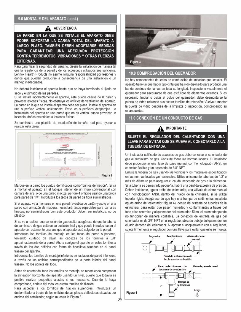
No hay componentes de lecho de combustible de imitación que instalar. Elaparato tiene un quemador tipo cinta que ha sido diseñado para producir unabanda continua de llamas en toda su longitud. Inspeccione visualmente elquemador para asegurarse de que está libre de elementos extraños. Si esnecesario limpiar o quitar el polvo del quemador, debe desmontarse lapuerta de vidrio retirando sus cuatro tornillos de retención. Vuelva a montarla puerta de vidrio después de la limpieza o inspección, comprobando suestanqueidad.
Un instalador calificado de aparatos de gas debe conectar el calentador degas al suministro de gas. Consulte todas las normas locales. El instaladordebe proporcionar una llave de paso manual con homologación ANSI, unconector flexible y un accesorio de 3/8" NPT. Enrute la tubería de gas usando las técnicas y los materiales especificadosen las normas locales y/o nacionales. Utilice únicamente tuberías de 1/2” omás de diámetro para asegurar el caudal necesario de gas a la chimenea.Si la tubería es demasiado pequeña, habrá una pérdida excesiva de presión.Deben instalarse, aguas arriba del calentador, una válvula de cierre manualcon homologación ANSI, dentro del hueco de la chimenea, si se utilizatubería rígida. Asegúrese de que hay una trampa de sedimentos instaladaaguas arriba del calentador (figura 4), dentro del sistema de tuberías de laestructura, para evitar que pasen humedad y contaminantes a través deltubo a los controles y al quemador del calentador. Si no, el calentador puedeno funcionar de manera confiable. La conexión de entrada de gas delcalentador es de 3/8” NPT en el regulador, ubicado debajo del quemador, enel lado derecho del calentador. Al apretar el acoplamiento con el regulador,sujete firmemente el regulador con una llave para evitar que éste se mueva.
20
Para garantizar la seguridad del usuario, diseñe la instalación de manera talque la resistencia de la pared y de los accesorios utilizados sea suficiente.Lennox Hearth Products no asume ninguna responsabilidad por lesiones ydaños que puedan producirse a consecuencia de una instalación o unmanejo inadecuados.
No deberá instalarse el aparato hasta que se haya terminado el lijado enseco y el pintado de las paredes.Si se instala incorrectamente el aparato, éste puede caerse de la pared yprovocar lesiones físicas. No obstruya los orificios de ventilación del aparato.La pared en la que se instale el aparato debe ser plana. Instale el aparato enuna superficie vertical únicamente. Evite las superficies desparejas. Lainstalación del aparato en una pared que no es vertical puede provocar unincendio, daños materiales o lesiones físicas.Se suministra una plantilla de instalación de tamaño real para ayudar arealizar esta tarea.
Marque en la pared los puntos identificados como "puntos de fijación". Si vaa montar el aparato en el tabique interior de un muro convencional concámara de aire, o de una pared maciza, perfore 4 orificios usando una brocapara pared de 1/4”. Introduzca los tacos de pared de fibra suministrados.Si el aparato va a montarse en una pared revestida de cartón-yeso o en unapared con armazón de madera, necesitará tacos especiales para cámarashuecas, no suministrados con este producto. Deben ser metálicos, no deplástico.Si se va a realizar una conexión de gas oculta, asegúrese de que la tuberíade suministro de gas está en su posición final y que puede introducirse en elaparato correctamente una vez que el aparato esté colgado en la pared.Introduzca los tornillos de montaje en los tacos de pared superiores,teniendo cuidado de dejar las cabezas de los tornillos a 3/8”aproximadamente de la pared. Ahora cuelgue el aparato en estos tornillos através de los dos orificios con forma de bocallave situados en el paneltrasero del aparato. Introduzca los tornillos de montaje inferiores en los tacos de pared inferiores,a través de los orificios correspondientes de la parte inferior del paneltrasero. No los apriete del todo.
Antes de apretar del todo los tornillos de montaje, se recomienda comprobarla alineación horizontal del aparato usando un nivel, puesto que todavía esposible realizar pequeños ajustes si es necesario. Cuando lo hayacomprobado, apriete del todo los cuatro tornillos de fijación. Para acceder a los tornillos de fijación superiores, introduzca undestornillador a través de los orificios de las placas deflectoras situadas porencima del catalizador, según muestra la Figura 3.
Figura 2
Figura 3
11.0 CONEXIÓN DE UN CONDUCTO DE GAS
9.0 MONTAJE DEL APARATO (cont.)
10.0 COMPROBACIÓN DEL QUEMADOR
LA PARED EN LA QUE SE INSTALE EL APARATO DEBEPODER SOPORTAR LA CARGA TOTAL DEL APARATO ALARGO PLAZO. TAMBIÉN DEBEN ADOPTARSE MEDIDASPARA GARANTIZAR UNA ADECUADA PROTECCIÓNCONTRA TERREMOTOS, VIBRACIONES Y OTRAS FUERZASEXTERNAS.
ADVERTENCIA
SUJETE EL REGULADOR DEL CALENTADOR CON UNALLAVE PARA EVITAR QUE SE MUEVA AL CONECTARLO A LATUBERÍA DE ENTRADA.
IMPORTANTE
Figura 4

Los puntos de prueba depresión están ubicadosen los lugares indicadosen la Figura 7. Un puntode prueba alternativo delquemador (colector) estáubicado debajo del lateralizquierdo del quemador,según muestra la Figura8. El regulador de presiónde los modelos manualesestá preajustado ybloqueado para evitar sumanipulación indebida. Sila presión no es laespecificada en la sec-ción "Especificacionesdel aparato" de la página2, sustituya el reguladorpor la pieza númeroH6063. Después de medir lapresión, vuelva a colocarlos tornillos del punto deprueba y asegúrese deque no haya fugas degas. Todas lasinstrucciones deben serentregadas al usuariopara su conservación.
El hueco entre el electrodo yel piloto debe ser de 1/8” a3/16” para producir unabuena chispa. No debe sernecesario ajustar estehueco. Si por algunacircunstancia el encendidopiezoeléctrico falla, el pilotono puede ser encendidomanualmente.
1. Retire el panel de vidrio del embalaje y colóquelo cara abajo en unasuperficie blanda. Identifique las partes superior e inferior del panel decorativode vidrio observando la orientación de las ranuras en forma de bocallave delos soportes de fijación del panel según se ilustra en la Figura 10.
21
Abra el suministro de gas y verifique que no hay fugas usando una soluciónpara detectar fugas de gas (también conocida como detector de burbujas).
NOTA: El uso de una solución de agua jabonosa (50% jabón de mano, 50%agua) es una solución eficaz para buscar fugas, pero no se recomiendaporque el residuo de jabón que queda en las tuberías y los acoplamientospuede producir corrosión con el tiempo.
A. Encienda el aparato (consulte la etiqueta de instrucciones de encendidodel compartimento de control o de la página 11).
B. Con un cepillo, cubra todas las juntas y conexiones con la solución parapruebas de fugas de gas para verificar que no hay fugas. Si se formanburbujas, o se detecta olor a gas, haga girar lala perilla de control del gas (apagado/piloto/encendido) hasta la posición“APAGADO” (OFF). Apriete o vuelva a montar la conexión que tiene la fuga,luego vuelva a comprobarla según descrito anteriormente.
C. Cuando haya probado las tuberías de gas y comprobado que no tienenfugas, asegúrese de limpiar la solución de prueba de fugas.
D. Observe las llamas individuales del quemador. Asegúrese de que todoslos orificios están abiertos y que producen llamas homogéneas en todo elquemador. Si algún orificio está obstruido total o parcialmente, límpielo.
La presión debe comprobarse con el calentador encendido y el controlpuesto en llama alta.Los puntos de pruebade presión estánubicados en la válvulade gas. Para accedera la válvula y a lospuntos de prueba,primero quite el clipde sujeción segúnmuestra la Figura 5,para retirar el husillode la perilla de controldel husillo de laválvula.
Retire la perilla decontrol y el husillo delcalentador, retire lacubierta de la válvulade gas quitando loscuatro tornillos deretención que seindican en la Figura 6.
12.0 COMPROBACIÓN DE LAS CONEXIONES DE GAS
13.0 COMPROBACIÓN DE LA PRESIÓN DEL GAS
Figura 5 Clip desujeción
Figura 6
Presióndelquemador(colector)
Ajuste dela presióndelregulador
Figura 7
Figura 8
14.0 ESPACIO ENTRE ELECTRODOS
Figura 9
Espacio entreelectrodos
PARTESUPERIOR
Figura 10
15.0 ARMADO DEL PANEL DECORATIVO DE VIDRIO
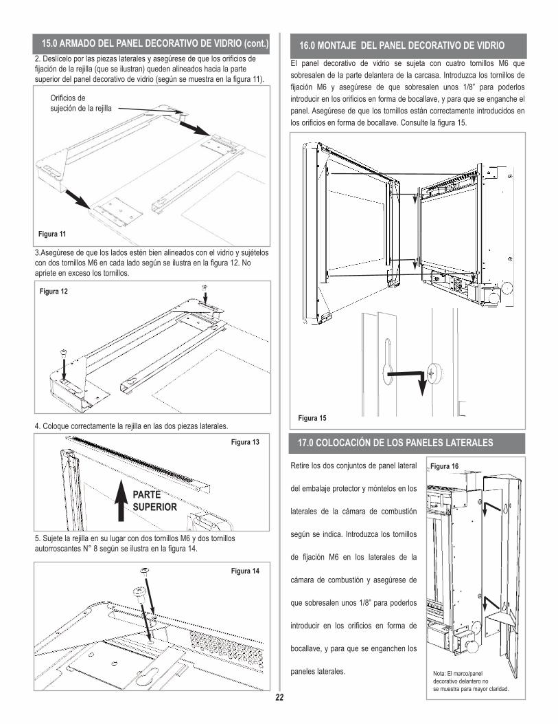
22
2. Deslícelo por las piezas laterales y asegúrese de que los orificios defijación de la rejilla (que se ilustran) queden alineados hacia la partesuperior del panel decorativo de vidrio (según se muestra en la figura 11).
3.Asegúrese de que los lados estén bien alineados con el vidrio y sujételoscon dos tornillos M6 en cada lado según se ilustra en la figura 12. Noapriete en exceso los tornillos.
4. Coloque correctamente la rejilla en las dos piezas laterales.
5. Sujete la rejilla en su lugar con dos tornillos M6 y dos tornillosautorroscantes N° 8 según se ilustra en la figura 14.
El panel decorativo de vidrio se sujeta con cuatro tornillos M6 quesobresalen de la parte delantera de la carcasa. Introduzca los tornillos defijación M6 y asegúrese de que sobresalen unos 1/8” para poderlosintroducir en los orificios en forma de bocallave, y para que se enganche elpanel. Asegúrese de que los tornillos están correctamente introducidos enlos orificios en forma de bocallave. Consulte la figura 15.
Retire los dos conjuntos de panel lateral
del embalaje protector y móntelos en los
laterales de la cámara de combustión
según se indica. Introduzca los tornillos
de fijación M6 en los laterales de la
cámara de combustión y asegúrese de
que sobresalen unos 1/8” para poderlos
introducir en los orificios en forma de
bocallave, y para que se enganchen los
paneles laterales.
16.0 MONTAJE DEL PANEL DECORATIVO DE VIDRIO15.0 ARMADO DEL PANEL DECORATIVO DE VIDRIO (cont.)
Orificios desujeción de la rejilla
Figura 12
Figura 11
PARTESUPERIOR
Figura 13
Figura 14
Figura 15
17.0 COLOCACIÓN DE LOS PANELES LATERALES
Nota: El marco/panel decorativo delantero no se muestra para mayor claridad.
Figura 16

23
Introduzca un destornillador através de los orificios delpanel de la derecha y aprietelos dos tornillos de fijación M6(tornillos ‘a’ en la figura 17).Luego introduzca dos tornillosautorroscantes Nº 8 (tornillos‘b’ en la figura 17) a través delsoporte del panel lateral y delos orificios correspondientesde la cámara de combustión.Apriete a fondo.
Repita para el panel de laizquierda, que se fijaapretando los tornillos M6 ‘a’solamente.
El panel de la derecha tieneun panel abisagrado parapermitir el acceso a la perillade control.
Después de la puesta en marcha del aparato, se debe instruir al clientesobre la seguridad en el uso del aparato y la necesidad de un mantenimientoregular. La frecuencia del mantenimiento depende del uso, pero esIMPRESCINDIBLE llevarlo a cabo al menos una vez al año.Avise al cliente que puede limpiar el calentador cuando éste está frío usandoun paño húmedo y un detergente suave en la mayoría de las superficies.Avísele que el calentador emitirá un “olor” durante cierto tiempo después dela puesta en marcha inicial y que puede ser necesario una ventilaciónadicional durante este periodo. Debe realizarse una comprobación visualperiódica de la llama del piloto y del quemador. (Consulte la figura 22).
El procedimiento de mantenimiento recomendado es el siguiente:
Cierre el paso de gas del calentador. Asegúrese de que el calentador se haenfriado totalmente antes de proceder al mantenimiento.
1. Disponga el paño de protección y las herramientas.2. Retire el panel decorativo de vidrio delantero según se indica en
la sección 16.0, pero en sentido inverso.3. Retire el conjunto de la puerta de vidrio (5 tornillos) y límpielo con
cuidado. Retire la cubierta de la válvula (4 tornillos).4. Inspeccione el quemador y los catalizadores y límpielos si es
necesario con un cepillo suave.5. Desconecte el suministro de gas.
6. Retire los cuatro tornillos que sujetan los soportes del quemadora la base y a la parte trasera de la cámara de combustión.
7. Retire la unidad del quemador, desmonte los tubos del quemadory limpie a fondo.
8. Limpie el restrictor en línea, el conjunto del piloto y el tubo delquemador. No intente retirar el inyector del piloto, puesto quepodría causar daños.
9. Vuelva a montar los componentes.10. Abra el paso de gas y compruebe que no hay fugas. Compruebe
que el piloto y el quemador se encienden correctamente.11. Vuelva a colocar la cubierta de la válvula y sus tornillos de
fijación.12. Vuelva a colocar el conjunto de la puerta de vidrio.13. Vuelva a colocar el panel decorativo según se describe en la
sección 15.0.14. Compruebe que la ventilación integrada no está obstruida. 15. Encienda el calentador y compruebe las presiones.16. Compruebe que el aparato funciona de manera segura. Consulte las secciones correspondientes si necesita instrucciones demantenimiento específicas.
Primero, retire el panel decorativo de vidrio delantero según se describe enla Sección 16.0, pero en sentido inverso, retire la tapa de la válvula (4tornillos) y desconecte el suministro de gas dentro del aparato. Ahorapueden liberarse las conexiones de gas a la válvula de gas. Retire los 4tornillos que sujetan los soportes del quemador a la base y a la parte traserade la cámara de combustión. Ahora puede retirarse el quemador.Retire los tubos del piloto y del quemador principal y sople a través de losmismos para desprender cualquier residuo. Ahora retire el codo del inyectory sople a través del mismo para asegurarse de que quede completamentelibre de obstrucciones. Desenganche el filtro de malla del piloto y límpiela con un cepillo suave.Limpie el exterior del conjunto del piloto con un cepillo suave y sople por losorificios de las llamas en el cabezal del piloto. Compruebe que los orificiosde aireación están libres de pelusas y suciedad. Si es necesario, el conjuntodel piloto puede retirarse desconectando el cable de alta tensión delelectrodo, el tubo de gas y el cable del termopar, y desatornillando lostornillos de montaje. El conjunto del piloto no admite mantenimiento y nodebe desmontarse. Los orificios de aireación deben estar completamentelibres de obstrucción por dentro para una operación correcta. NUNCAMODIFIQUE NI DOBLE EL TERMOPAR PARA HACER QUE EL PILOTO SEMANTENGA ENCENDIDO. Las modificaciones son peligrosas y puedentener graves efectos no visibles en la seguridad. Si el piloto no permaneceencendido, hay un problema con la suciedad o con el suministro de gas, o eltermopar debe ser sustituido. La válvula de gas es un elemento que no admite mantenimiento. Si esnecesario sustituirla, retire la cubierta y luego el tornillo que sujeta el soportede la válvula, retire todos los acoplamientos de tubos, y la válvula completa.Debe sustituirse con piezas del fabricante original.Vuelva a montar las piezas en orden inverso. Compruebe que las presionesson las indicadas en la Sección 3: Especificaciones del aparato.
17.0 COLOCACIÓN DE LOS PANELES LATERALES (cont.)
19.0 MANTENIMIENTO
20.0 MANTENIMIENTO DEL QUEMADOR
‘a’
‘a’
‘b’‘b’
Figura 17
18.0 INFORMACIÓN AL CLIENTE
NO AÑADA TRONCOS U ELEMENTOS DECORATIVOSTALES COMO PIÑAS, VERMICULITA O LANA MINERAL.EL USO DE ESTOS ELEMENTOS ADICIONALES PUEDECAUSAR LA GENERACIÓN DE HOLLÍN.
ADVERTENCIA CUALQUIER MODIFICACIÓN DE ESTE APARATO Y/OSUS CONTROLES DE OPERACIÓN PUEDE SERPELIGROSO.
ADVERTENCIA

Retire el panel decorativo de vidrio, la puerta de vidrio y el conjunto delquemador (según lo indicado en la sección de mantenimiento), el filtro demalla y el conjunto del piloto usando un destornillador para retirar lostornillos de fijación. Limpie el conjunto del piloto con un cepillo suave y soplea través del mismo. Compruebe que los orificios de aireación están libresde pelusas y suciedad. Limpie a fondo el interior; es posible retirar elconector de la base del conjunto del piloto usando dos llaves para facilitar lalimpieza. No dañe el inyector del piloto, ni intente desmontarlo. El conjuntoes preajustado en fábrica, y la única comprobación necesaria es asegurarque el espacio entre electrodos es correcto. Consulte las especificacionespara el ajuste de gas.NUNCA MODIFIQUE NI DOBLE EL TERMOPAR PARA HACER QUE ELPILOTO SE MANTENGA ENCENDIDO. Si el piloto no permaneceencendido, hay un problema de suciedad o con el suministro de gas, o eltermopar debe ser sustituido. Las modificaciones son peligrosas y puedentener graves efectos no visibles en la seguridad; por tanto, NO DEBENhacerse. Debe sustituirse con piezas del fabricante original. Vuelva a montarlas piezas en orden inverso. Compruebe que las presiones son las indicadasen la Sección 3: Especificaciones del aparato.
Se recomienda inspeccionar los catalizadores en busca de señales dedaños y suciedad durante los procedimientos de mantenimiento de rutina. Lavida prevista de los catalizadores es de más de 11.000 horas (10 años deuso normal). Después de este tiempo es necesario cambiar el catalizador. Sihay acumulaciones de suciedad u hollín en los catalizadores, deben limpiar-se con un cepillo suave y una aspiradora. Si se retiran para su limpieza,asegúrese de que las juntas están en buenas condiciones antes de volver ainstalar el catalizador. Normalmente se necesitarán juntas nuevas.El rendimiento del catalizador puede comprobarse usando un analizador degases de combustión, según se explica a continuación. Importante: Latemperatura de los gases emitidos por los convertidores catalíticos superalos 700 oF. La medición de gases a esta temperatura puede dañar algunos
tipos de analizadores de gases. En caso de duda, consulte al fabricanteequipo.Encienda la chimenea siguiendo las instrucciones de uso y deje quefuncione durante 15 minutos. Ponga la sonda del analizador de gasdirectamente encima de un catalizador a través de la rejilla de salida, en laparte superior del aparato. Anote la concentración de dióxido de carbono(CO2) y luego la concentración de monóxido de carbono (CO) mostradaspor el analizador, así como las unidades en que se muestran los valores. Lamayoría de los analizadores muestra las concentraciones de dióxido decarbono (CO2) en porcentajes (%) y las de monóxido de carbono en partespor millón (ppm).Para calcular la razón de combustión del aparato (CO/CO2) es necesarioprimero expresar ambas concentraciones de gas como porcentaje. Paraconvertir desde partes por millón (ppm) a un porcentaje (%) divida la figuraen ppm por 10.000. Ejemplos: 35ppm = 0,0035%, 15ppm = 0,0015%, 5ppm= 0,0005%.Ahora, divida la concentración de monóxido de carbono (CO) expresadacomo porcentaje por la concentración de dióxido de carbono (CO2) paraobtener la razón de combustión del aparato.
La razón de combustión de los gases emitidos por el convertidor catalíticono debe superar 0,0015. En caso de sustitución, primero retire el paneldecorativo de vidrio según lo indicado en la Sección 15.0. Los catalizadoresse encuentran encima de la cámara de combustión interna, y puedenretirarse desatornillando las tuercas de retención de la placa de sujeción.Retire el catalizador y las juntas, y deséchelos. Coloque un catalizadornuevo y las juntas correspondientes en orden inverso, asegurando que elcatalizador y la puerta queden estancos.
Si un aparato tiene varios años de antigüedad o ha sido desmontado variasveces, es necesario comprobar su estanqueidad. Es importante que todoslos productos de la combustión pasen a través de los convertidorescatalíticos situados en la parte superior de la cámara de combustión antesde salir del aparato.Caliente la cámara de combustión encendiendo el aparato durante unosminutos para generar un flujo de aire a través de la cámara de combustión.Apague el quemador e introduzca una pastilla de humo o un fósforo en labase del calentador, debajo de la bandeja del quemador. Saldrán grandescantidades de humo de la parte superior del aparato, pero no debe salirhumo de las uniones o de las juntas, sobre todo alrededor de la puerta. Esimportante observar que el aparato nunca podrá ser estanco al humo al100%, y podrán verse pequeñas cantidades de humo en esquinas, unionesy juntas, incluso con la chimenea encendida, sin afectar la seguridad.
PANEL DE VIDRIO - Puede limpiarse con un producto para cristalesapropiado. Las siguientes soluciones están aprobadas para usarse en lalimpieza del vidrio.
• Producto limpiador de uso doméstico sin amoníaco• Mezcla de vinagre blanco y agua en partes iguales• Producto de limpieza para vidrios de calentadores/estufas de gas
Pruebe primero en una zona pequeña.ZONAS PINTADAS - Pueden limpiarse con un paño seco.ZONAS DE METAL ACABADO - Pueden limpiarse usando un limpiadorcomercial para metal o aceite para niños. Pruebe primero en una parte novisible. Limpie siempre en el sentido del “veteado”.
24
22.0 CATALIZADORES
CO (%)CO2 (%) = razón
23.0 COMPROBACIÓN DE FUGAS DE LACÁMARA DE COMBUSTIÓN
24.0 LIMPIEZA
21.0 CONJUNTO DEL PILOTO
NO DEBEN EFECTUARSE AJUSTES EN EL SISTEMA DEPILOTO ODS. LA MANIPULACIÓN DE ESTE SISTEMAPUEDE SER EXTREMADAMENTE PELIGROSA.
ADVERTENCIA
NOOBSTRUYA LOS CATALIZADORES NI LA REJILLA DESALIDA DEL APARATO. SI SE OBSTRUYEN, PUEDENACUMULARSE ALTOS NIVELES DE MONÓXIDO DE CARBONOO PUEDE ROMPERSE ELPANELDECORATIVO DE VIDRIO.
ADVERTENCIA
NO UTILICE EL APARATO SI SE HAN QUITADO LOSCATALIZADORES.
ADVERTENCIA
Figura 18 NO OBSTRUYAESTAS ZONAS
APAGUE EL CALENTADOR DE GAS SIN SALIDA DEHUMOS Y DEJE QUE SE ENFRÍE ANTES DELIMPIARLO.
ADVERTENCIA
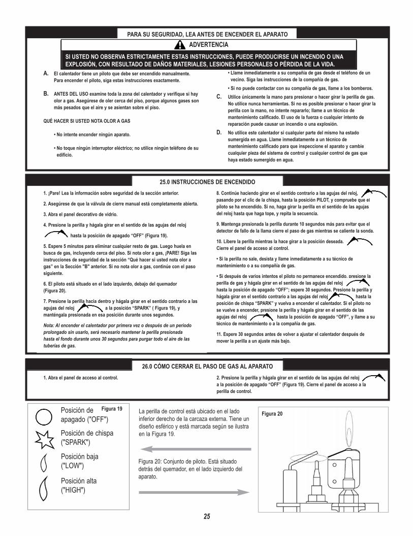
25
PARA SU SEGURIDAD, LEA ANTES DE ENCENDER EL APARATO
A. El calentador tiene un piloto que debe ser encendido manualmente.Para encender el piloto, siga estas instrucciones exactamente.
B. ANTES DEL USO examine toda la zona del calentador y verifique si hayolor a gas. Asegúrese de oler cerca del piso, porque algunos gases sonmás pesados que el aire y se asientan sobre el piso.
QUÉ HACER SI USTED NOTA OLOR A GAS
• No intente encender ningún aparato.
• No toque ningún interruptor eléctrico; no utilice ningún teléfono de suedificio.
• Llame inmediatamente a su compañía de gas desde el teléfono de unvecino. Siga las instrucciones de la compañía de gas.
• Si no puede contactar con su compañía de gas, llame a los bomberos.C. Utilice únicamente la mano para presionar o hacer girar la perilla de gas.
No utilice nunca herramientas. Si no es posible presionar o hacer girar laperilla con la mano, no intente repararlo; llame a un técnico demantenimiento calificado. El uso de la fuerza o cualquier intento dereparación puede causar un incendio o una explosión.
D. No utilice este calentador si cualquier parte del mismo ha estadosumergida en agua. Llame inmediatamente a un técnico demantenimiento calificado para que inspeccione el aparato y cambiecualquier pieza del sistema de control y cualquier control de gas quehaya estado sumergido en agua.
25.0 INSTRUCCIONES DE ENCENDIDO1. ¡Pare! Lea la información sobre seguridad de la sección anterior.
2. Asegúrese de que la válvula de cierre manual está completamente abierta.
3. Abra el panel decorativo de vidrio.
4. Presione la perilla y hágala girar en el sentido de las agujas del reloj
hasta la posición de apagado “OFF” (Figura 19).
5. Espere 5 minutos para eliminar cualquier resto de gas. Luego huela enbusca de gas, incluyendo cerca del piso. Si nota olor a gas, ¡PARE! Siga lasinstrucciones de seguridad de la sección “Qué hacer si usted nota olor agas” en la Sección "B" anterior. Si no nota olor a gas, continúe con el pasosiguiente.
6. El piloto está situado en el lado izquierdo, debajo del quemador (Figura 20).
7. Presione la perilla hacia dentro y hágala girar en el sentido contrario a lasagujas del reloj a la posición “SPARK” ( Figura 19), ymanténgala presionada en esa posición durante unos segundos.
Nota: Al encender el calentador por primera vez o después de un periodoprolongado sin usarlo, será necesario mantener la perilla presionada hasta el fondo durante unos 30 segundos para purgar todo el aire de las tuberías de gas.
8. Continúe haciendo girar en el sentido contrario a las agujas del reloj,pasando por el clic de la chispa, hasta la posición PILOT, y compruebe que elpiloto se ha encendido. Si no, haga girar la perilla en el sentido de las agujasdel reloj hasta que haga tope, y repita la secuencia.
9. Mantenga presionada la perilla durante 10 segundos más para evitar que eldetector de fallo de la llama cierre el paso de gas mientras se caliente la sonda.
10. Libere la perilla mientras la hace girar a la posición deseada. Cierre el panel de acceso al control.
• Si la perilla no sale, desista y llame inmediatamente a su técnico demantenimiento o a su compañía de gas.
• Si después de varios intentos el piloto no permanece encendido, presione laperilla de gas y hágala girar en el sentido de las agujas del relojhasta la posición de apagado “OFF”; espere 30 segundos. Presione la perilla yhágala girar en el sentido contrario a las agujas del reloj hasta laposición de chispa “SPARK” y vuelva a encender el calentador. Si el piloto nose vuelve a encender, presione la perilla y hágala girar en el sentido de lasagujas del reloj hasta la posición de apagado “OFF”, y llame a sutécnico de mantenimiento o a la compañía de gas.
11. Espere 30 segundos antes de volver a ajustar el calentador después demover la perilla a un ajuste más bajo.
26.0 CÓMO CERRAR EL PASO DE GAS AL APARATO2. Presione la perilla y hágala girar en el sentido de las agujas del reloja la posición de apagado “OFF” (Figura 19). Cierre el panel de acceso a laperilla de control.
1. Abra el panel de acceso al control.
SI USTED NO OBSERVA ESTRICTAMENTE ESTAS INSTRUCCIONES, PUEDE PRODUCIRSE UN INCENDIO O UNAEXPLOSIÓN, CON RESULTADO DE DAÑOS MATERIALES, LESIONES PERSONALES O PÉRDIDA DE LA VIDA.
ADVERTENCIA
Figura 20: Conjunto de piloto. Está situadodetrás del quemador, en el lado izquierdo delaparato.
Figura 20La perilla de control está ubicado en el ladoinferior derecho de la carcaza externa. Tiene undiseño esférico y está marcada según se ilustraen la Figura 19.
Posición deapagado ("OFF")
Posición de chispa("SPARK")
Posición baja("LOW")
Posición alta ("HIGH")
Figura 19

26
Se produce una chispa pero el piloto no se No llega gas al piloto, compruebe las conexiones de la tubería de gas. enciende El aire no se ha purgado del todo: vuelva a purgar el aire, o espere más tiempo.
Derivación de la chispa a una pieza metálica: ajuste correctamente el espacio entre electrodos. Piloto obstruido: limpiar internamente.
El piloto se enciende, luego se apaga Importante restricción en el suministro de gas: eliminar la obstrucción. Termopar defectuoso: cambie el conjunto del piloto. Piloto obstruido: limpiar. Filtro de malla obturado: limpiar Mantenga pulsada la perilla de control durante más tiempo. Compruebe que la perilla de control no choca con la placa de datos.Si el piloto no permanece encendido, hay un problema de suciedad o con el suministro de gas, o eltermopar debe ser sustituido. Las modificaciones son peligrosas y pueden tener graves efectos no visiblesen la seguridad. NUNCA MODIFIQUE NI DOBLE EL TERMOPAR PARA HACER QUE EL PILOTO SEMANTENGA ENCENDIDO.
No se produce una chispa en el piloto Cable de alta tensión suelto: reconectar. Compruebe el espacio entre electrodos (ver Sección 14.0).Unidad piezoeléctrica defectuosa: cambiar. Cortocircuito en el electrodo: limpiar. Derivación de la chispa a piezas metálicas debajo de la bandeja: volver a alinear el cabezal de alta tensión.
El calentador funciona durante un Termopar suelto o defectuoso: rectificar. tiempo, luego se apaga Piloto obstruido: limpiar.
Suciedad o pelusas en el orificio de aireación del piloto o en el filtro de malla: limpiar a fondo. Si el piloto no permanece encendido, hay un problema de suciedad o con el suministro de gas, o eltermopar debe ser sustituido. Las modificaciones son peligrosas y pueden tener graves efectos no visiblesen la seguridad. NUNCA MODIFIQUE NI DOBLE EL TERMOPAR PARA HACER QUE EL PILOTO SEMANTENGA ENCENDIDO.
La llama del piloto se reduce cuando el Flujo defectuoso de gas al calentador: compruebe la presión con el calentador en Alto. calentador está en Alto Si la presión es baja, elimine cualquier restricción en la tubería o la válvula.
Compruebe que toda la tubería sea del tamaño correcto. Compruebe que hay suficiente presión en el contador. Si el piloto no permanece encendido, hay un problema de suciedad o con el suministro de gas, o eltermopar debe ser sustituido. Las modificaciones son peligrosas y pueden tener graves efectos no visiblesen la seguridad. NUNCA MODIFIQUE NI DOBLE EL TERMOPAR PARA HACER QUE EL PILOTO SEMANTENGA ENCENDIDO.
Hay olor a gas al encenderse o utilizarse el Olor “a nuevo” del aparato. calentador por primera vez Fuga. Realice prueba de fugas y resuelva cualquier problema.
Materiales utilizados en lugares no apropiados.Es posible que la unidad necesite mantenimiento para eliminar el polvo de los catalizadores.
27.0 GUÍA DE SOLUCIÓN DE PROBLEMAS
28.0 PIEZAS DE REPUESTO
Descripción Nº de CatálogoConjunto de puerta de vidrio H6055Válvula de gas H6059Catalizador H6060Montaje del piloto H6061Conjunto de quemador H6056Kit de junta para catalizador H6062Regulador de la presión de entrada H6063Panel decorativo de vidrio H6068
Al pedir piezas de repuesto, proporcione siempre la siguiente información:1. El número de modelo del calentador.2. El número de serie del calentador.3. El número de pieza.4. La descripción de la pieza.5. La cantidad solicitada.6. La fecha de instalación del calentador.
Si usted encuentra problemas, necesita piezas de repuesto o tiene algunapregunta sobre la instalación del calentador, póngase en contacto con sudistribuidor. Para saber cuál es el distribuidor más cercano a su domicilio,diríjase a:
LENNOX HEARTH PRODUCTS1110 West Taft Avenue Orange, CA 92865Teléfono: 1-800-9-Lennoxvisítenos en www.Lennox.com
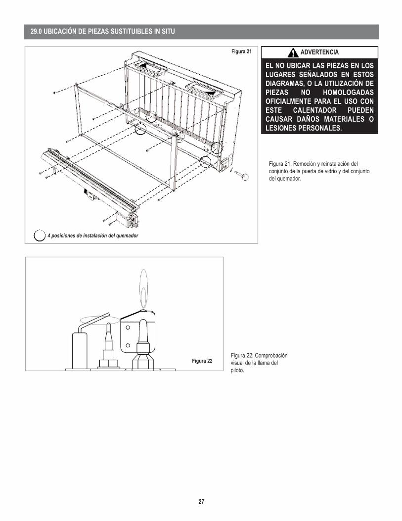
27
Figura 22
Figura 21: Remoción y reinstalación delconjunto de la puerta de vidrio y del conjuntodel quemador.
Figura 22: Comprobaciónvisual de la llama delpiloto.
29.0 UBICACIÓN DE PIEZAS SUSTITUIBLES IN SITU
Figura 21
4 posiciones de instalación del quemador
EL NO UBICAR LAS PIEZAS EN LOSLUGARES SEÑALADOS EN ESTOSDIAGRAMAS, O LA UTILIZACIÓN DEPIEZAS NO HOMOLOGADASOFICIALMENTE PARA EL USO CONESTE CALENTADOR PUEDENCAUSAR DAÑOS MATERIALES OLESIONES PERSONALES.
ADVERTENCIA

14
1110 West Taft Avenue • Orange, CA 92865
NOTA: LOS DIAGRAMAS Y LAS ILUSTRACIONES NO ESTÁN A ESCALA
Lennox se reserva el derecho de modificar, en cualquier momento y sin previo aviso eldiseño, los materiales, las especificaciones y los precios, así como también discontinuarcolores, estilos y productos.Consulte a su distribuidor local para obtener información sobre los códigos del calentador.
LENNOX HEARTH PRODUCTSP/N 850,054M REV. NC 04/2007
Calentadores de gas, estufas y accesorios Lennox Hearth ProductsGarantía limitada por 20 años
GARANTÍALennox Hearth Products ("LHP") garantiza que su calentador de gas, aparato, estufa o accesorio ("el Producto") está libre de defectos de materiales y mano de obra en el momento de sufabricación. Después de la instalación, si alguno de los componentes del Producto fabricado por LHP presenta defectos de materiales o mano de obra durante el periodo de cobertura de la garantíade 20 años y mientras el Producto se conserve en el lugar de instalación original, LHP, a su opción, sustituirá o reparará los componentes defectuosos. Asimismo, correrán por cuenta de LHP losgastos razonables de mano de obra en los que se incurra para sustituir o reparar dichos componentes por un periodo de un año a partir de la fecha de instalación. EXISTEN EXCLUSIONES YLIMITACIONES DE esta garantía limitada, las que se describen en este documento.
EXCLUSIONES Y LIMITACIONESEsta Garantía limitada se aplicará sólo si el Producto se instala en los EE.UU. o Canadá y sólo si se utiliza y mantiene según las instrucciones impresas que acompañan el Producto y de acuerdocon la normativa aplicable de instalación y construcción, y las buenas prácticas comerciales. En caso de que la sustitución o reparación no sea comercialmente posible, LHP, a su opción,reembolsará el precio de compra del Producto LHP.
La cámara de combustión y la caja se garantizan por veinte (20) años a partir de la fecha de instalación de la siguiente en las siguientes condiciones: Primer año: piezas sin cargo y gastosrazonables de mano de obra. Desde el segundo hasta el quinto año: sólo las piezas sin cargo. Desde el sexto hasta el vigésimo año: sólo las piezas al 50% del precio de lista vigente. Loscomponentes de ventilación y los de latón, la pintura, los accesorios opcionales y las puertas de vidrio opcionales quedan excluidas de la presente Garantía limitada. LHP ofrece una garantíalimitada independiente para las puertas de vidrio opcionales fabricadas por LHP. Los siguientes componentes NO están garantizados por 20 años sino que están cubiertos por otro tipo de garantíaen las condiciones que se establecen a continuación:
Controles: la reparación o sustitución por un año a partir de la fecha de instalación.Quemador: la reparación o sustitución por un año a partir de la fecha de instalación.Componentes de vidrio: la reparación o sustitución por un año a partir de la fecha de instalación. El vidrio cerámico se garantiza contra roturas térmicas sólo por unperiodo de dos años a partir de la fecha de instalación.Juntas: la reparación o sustitución por un año a partir de la fecha de instalación.Leños: la reparación o sustitución por un año a partir de la fecha de instalación.Catalizador: dos años las piezas y la mano de obra; desde el tercer hasta el quinto año, sólo las piezas a partir de la fecha de instalación.
LHP no responderá de: (a) los daños causados por accidentes, disturbios, incendios, inundaciones o caso fortuito; (b) los daños causados por abuso, negligencia, mal uso o modificación noautorizada ni reparación del Producto que afecte su estabilidad o rendimiento (El Producto debe ser sometido a un uso normal. El Producto está diseñado para usarse con gas natural o propanoexclusivamente. El uso de combustibles convencionales como madera, carbón o cualquier otro combustible sólido dañará el Producto, generará temperaturas excesivas y provocará un peligrode incendio); (c) los daños que se produzcan por no proporcionarse el debido mantenimiento de acuerdo con las instrucciones provistas con el Producto; (d) los daños, las reparaciones o laineficiencia que deriven de la instalación o el uso defectuosos del Producto.
Esta Garantía limitada sólo cubre las piezas y la mano de obra según lo establecido en este documento. En ningún caso LHP será responsable de los materiales, componentes o la construcciónque no sean fabricados o provistos por LHP ni de la mano de obra necesaria para instalar, reparar o quitar estos materiales, componentes o construcción. Todos los componentes de reparacióno sustitución se enviarán F.O.B. desde la fábrica de LHP más próxima.
LIMITACIÓN DE RESPONSABILIDADSe conviene y acuerda expresamente que la única obligación de LHP y el recurso exclusivo del comprador en virtud de esta garantía y de cualquier otra garantía, expresa o tácita,por responsabilidad contractual o extracontractual, o de otra naturaleza, se limitará a la sustitución, la reparación o el reembolso, según se especifica en este documento. En ningúncaso LHP responderá de los daños indirectos o incidentales causados por defectos del Producto, ya sea que el daño se produzca o se detecte antes de la sustitución o reparacióno después de ellas, y al margen de que el daño sea causado por negligencia de LHP. LHP no declara ni garantiza la aptitud para un uso o fin determinados y no existe ningunacondición implícita de aptitud para un uso o fin determinados.
No concedemos ninguna otra garantía expresa salvo lo establecido en la presente Garantía limitada. El periodo de vigencia de cualquier garantía tácita se limita al de la presentegarantía expresa.
Ninguna persona está autorizada a modificar la presente Garantía limitada ni a crear en nuestro nombre ninguna otra obligación o responsabilidad relacionada con el Producto.Algunos estados y provincias no permiten la exclusión o limitación de los daños indirectos o incidentales; por lo tanto, es posible que las limitaciones o exclusiones antesmencionadas no se apliquen en su caso. Las estipulaciones de la presente Garantía limitada se agregan a las garantías legales y los demás derechos y recursos establecidos en laley, y no los modifican ni excluyen.
INVESTIGACIÓN DE RECLAMACIONES DE LA GARANTÍALHP se reserva el derecho de investigar todas y cada una de las reclamaciones en virtud de la presente Garantía limitada y determinar el método de resolución.
LHP NO RESPONDERÁ DEL TRABAJO REALIZADO SIN SU CONSENTIMIENTO POR ESCRITOPara gozar de los beneficios y las ventajas que se describen en la presente Garantía limitada, el aparato debe ser instalado y reparado por un contratista con licencia, autorizado por LHP. Diríjasea LHP en la dirección que se indica en este documento a fin de obtener una lista de los distribuidores autorizados. En ningún caso, LHP responderá del trabajo cubierto por la garantía y realizadopor un contratista que no está autorizado sin el consentimiento previo por escrito de LHP.
CÓMO PRESENTAR UNA RECLAMACIÓN EN VIRTUD DE LA GARANTÍAPara que la reclamación en virtud de la presente Garantía sea válida, debe notificarse a LHP el defecto reclamado por escrito con la mayor brevedad posible, una vez quese lo haya detectado. La notificación debe dirigirse a LHP, atención Customer Service Department (Departamento de Atención al Cliente), 1110 West Taft Avenue, Orange, CA 92865. En lasreclamaciones por escrito debe incluirse la fecha de instalación y una descripción del defecto.