Catalyst 3560-CX and 2960-CX Switch Hardware Installation ... · Catalyst 3560-CX and 2960-CX...
92
Catalyst 3560-CX and 2960-CX Switch Hardware Installation Guide First Published: 2015-02-05 Last Modified: 2015-06-24 Americas Headquarters Cisco Systems, Inc. 170 West Tasman Drive San Jose, CA 95134-1706 USA http://www.cisco.com Tel: 408 526-4000 800 553-NETS (6387) Fax: 408 527-0883
Transcript of Catalyst 3560-CX and 2960-CX Switch Hardware Installation ... · Catalyst 3560-CX and 2960-CX...
Catalyst 3560-CX and 2960-CX Switch Hardware Installation GuideFirst Published: 2015-02-05
Last Modified: 2015-06-24
Americas HeadquartersCisco Systems, Inc.170 West Tasman DriveSan Jose, CA 95134-1706USAhttp://www.cisco.comTel: 408 526-4000 800 553-NETS (6387)Fax: 408 527-0883
THE SPECIFICATIONS AND INFORMATION REGARDING THE PRODUCTS IN THIS MANUAL ARE SUBJECT TO CHANGE WITHOUT NOTICE. ALL STATEMENTS,INFORMATION, AND RECOMMENDATIONS IN THIS MANUAL ARE BELIEVED TO BE ACCURATE BUT ARE PRESENTED WITHOUT WARRANTY OF ANY KIND,EXPRESS OR IMPLIED. USERS MUST TAKE FULL RESPONSIBILITY FOR THEIR APPLICATION OF ANY PRODUCTS.
THE SOFTWARE LICENSE AND LIMITEDWARRANTY FOR THE ACCOMPANYING PRODUCT ARE SET FORTH IN THE INFORMATION PACKET THAT SHIPPED WITHTHE PRODUCT AND ARE INCORPORATED HEREIN BY THIS REFERENCE. IF YOU ARE UNABLE TO LOCATE THE SOFTWARE LICENSE OR LIMITED WARRANTY,CONTACT YOUR CISCO REPRESENTATIVE FOR A COPY.
The following information is for FCC compliance of Class A devices: This equipment has been tested and found to comply with the limits for a Class A digital device, pursuant to part 15of the FCC rules. These limits are designed to provide reasonable protection against harmful interference when the equipment is operated in a commercial environment. This equipmentgenerates, uses, and can radiate radio-frequency energy and, if not installed and used in accordance with the instruction manual, may cause harmful interference to radio communications.Operation of this equipment in a residential area is likely to cause harmful interference, in which case users will be required to correct the interference at their own expense.
The following information is for FCC compliance of Class B devices: This equipment has been tested and found to comply with the limits for a Class B digital device, pursuant to part 15of the FCC rules. These limits are designed to provide reasonable protection against harmful interference in a residential installation. This equipment generates, uses and can radiate radiofrequency energy and, if not installed and used in accordance with the instructions, may cause harmful interference to radio communications. However, there is no guarantee that interferencewill not occur in a particular installation. If the equipment causes interference to radio or television reception, which can be determined by turning the equipment off and on, users areencouraged to try to correct the interference by using one or more of the following measures:
• Reorient or relocate the receiving antenna.
• Increase the separation between the equipment and receiver.
• Connect the equipment into an outlet on a circuit different from that to which the receiver is connected.
• Consult the dealer or an experienced radio/TV technician for help.
Modifications to this product not authorized by Cisco could void the FCC approval and negate your authority to operate the product
The Cisco implementation of TCP header compression is an adaptation of a program developed by the University of California, Berkeley (UCB) as part of UCB’s public domain versionof the UNIX operating system. All rights reserved. Copyright © 1981, Regents of the University of California.
NOTWITHSTANDINGANYOTHERWARRANTYHEREIN, ALL DOCUMENT FILES AND SOFTWAREOF THESE SUPPLIERS ARE PROVIDED "AS IS"WITHALL FAULTS.CISCO AND THE ABOVE-NAMED SUPPLIERS DISCLAIM ALL WARRANTIES, EXPRESSED OR IMPLIED, INCLUDING, WITHOUT LIMITATION, THOSE OFMERCHANTABILITY, FITNESS FORA PARTICULAR PURPOSEANDNONINFRINGEMENTORARISING FROMACOURSEOFDEALING, USAGE, OR TRADE PRACTICE.
IN NO EVENT SHALL CISCO OR ITS SUPPLIERS BE LIABLE FOR ANY INDIRECT, SPECIAL, CONSEQUENTIAL, OR INCIDENTAL DAMAGES, INCLUDING, WITHOUTLIMITATION, LOST PROFITS OR LOSS OR DAMAGE TO DATA ARISING OUT OF THE USE OR INABILITY TO USE THIS MANUAL, EVEN IF CISCO OR ITS SUPPLIERSHAVE BEEN ADVISED OF THE POSSIBILITY OF SUCH DAMAGES.
Any Internet Protocol (IP) addresses and phone numbers used in this document are not intended to be actual addresses and phone numbers. Any examples, command display output, networktopology diagrams, and other figures included in the document are shown for illustrative purposes only. Any use of actual IP addresses or phone numbers in illustrative content is unintentionaland coincidental.
Cisco and the Cisco logo are trademarks or registered trademarks of Cisco and/or its affiliates in the U.S. and other countries. To view a list of Cisco trademarks, go to this URL: http://www.cisco.com/go/trademarks. Third-party trademarks mentioned are the property of their respective owners. The use of the word partner does not imply a partnershiprelationship between Cisco and any other company. (1110R)
© 2015 Cisco Systems, Inc. All rights reserved.
C O N T E N T S
P r e f a c e Preface vii
Document Conventions vii
Related Documentation ix
Obtaining Documentation and Submitting a Service Request ix
C H A P T E R 1 Product Overview 1
Switch Models 1
Front Panel 2
PoE and PoE+ Ports 4
10/100/1000 Ports 4
Multigigabit ports 5
Management Ports 5
SFP and SFP+ Module Slots 6
LEDs 6
System LED 7
Modes for Port LEDs 7
PoE LED 8
Console LEDs 8
Port LEDs 8
Rear Panel 9
Internal Power Supply 12
Security Slot 12
Auxiliary Power Adapter 12
Management Options 13
Network Configurations 14
C H A P T E R 2 Switch Installation 15
Catalyst 3560-CX and 2960-CX Switch Hardware Installation Guide iii
Warnings 15
Box Contents 17
Tools and Equipment 18
Installation Guidelines 18
Verifying Switch Operation 19
Mounting the Switch 20
Mounting on a Desk or Shelf Without Mounting Screws 20
On a Desk, Shelf, or Wall (with Mounting Screws) 21
Desk- or Shelf-Mounting 21
Under a Desk- or Shelf-Mounting 22
Wall-Mounting 24
With a Mounting Tray 26
Mounting Tray with Screws 27
Mounting Tray with a Magnet 29
In a Rack 31
On a DIN Rail 33
Attaching the DIN-Mount Tray to the Switch 34
Mounting the Switch on a DIN Rail 35
Removing the Switch from a DIN Rail 37
Attaching the Adapter Bracket to the Switch (Optional) 38
Installing the Power Cord Retainer (Optional) 39
Installing the Cable Guard (Optional) 42
Installing SFP and SFP+Modules 46
Installing an SFP or SFP+Module 46
Removing an SFP or SFP+Module 47
10/100/1000 PoE and PoE+Port Connections 47
10/100/1000 Port Connections 49
Auto-MDIX Connections 49
Where to Go Next 49
C H A P T E R 3 Troubleshooting 51
Diagnosing Problems 51
Switch POST Results 51
Switch LEDs 51
Switch Connections 52
Catalyst 3560-CX and 2960-CX Switch Hardware Installation Guideiv
Contents
Bad or Damaged Cable 52
Ethernet and Fiber-Optic Cables 52
Link Status 52
10/100/1000 Port Connections 53
10/100/1000 PoE+ Port Connections 53
SFP and SFP+ Module 53
Interface Settings 54
Ping End Device 54
Spanning Tree Loops 54
Switch Performance 54
Speed, Duplex, and Autonegotiation 54
Autonegotiation and Network Interface Cards 54
Cabling Distance 55
Resetting the Switch 55
Finding the Switch Serial Number 56
A P P E N D I X A Technical Specifications 57
Environmental Specifications 58
Physical Specifications 59
Power Requirements 60
PoE Power Consumption 61
A P P E N D I X B Connector and Cable Specifications 63
Connector Specifications 63
10/100/1000 Ports (Including PoE) 63
SFP Module Connectors 64
Cables and Adapters 64
SFP Module Cables 64
Cable Pinouts 66
Console Port Adapter Pinouts 67
A P P E N D I X C Configuring the Switch with the CLI-Based Setup Program 69
Accessing the CLI Through Express Setup 69
Accessing the CLI Through the Console Port 69
Connecting the RJ-45 Console Port 70
Catalyst 3560-CX and 2960-CX Switch Hardware Installation Guide v
Contents
Connecting the USB Console Port 71
Installing the Cisco Microsoft Windows USB Device Driver 73
Installing the Cisco Microsoft Windows XP USB Driver 73
Installing the Cisco Microsoft Windows 2000 USB Driver 74
Installing the Cisco Microsoft Windows Vista and Windows 7 USB Driver 75
Uninstalling the Cisco Microsoft Windows USB Driver 75
Uninstalling the Cisco Microsoft Windows XP and 2000 USB Driver 75
Using the Setup.exe Program 75
Using the Add or Remove Programs Utility 76
Uninstalling the Cisco Microsoft Windows Vista and Windows 7 USB Driver 76
Entering the Initial Configuration Information 77
IP Settings 77
Completing the Setup Program 78
Catalyst 3560-CX and 2960-CX Switch Hardware Installation Guidevi
Contents
Preface
• Document Conventions, page vii
• Related Documentation, page ix
• Obtaining Documentation and Submitting a Service Request, page ix
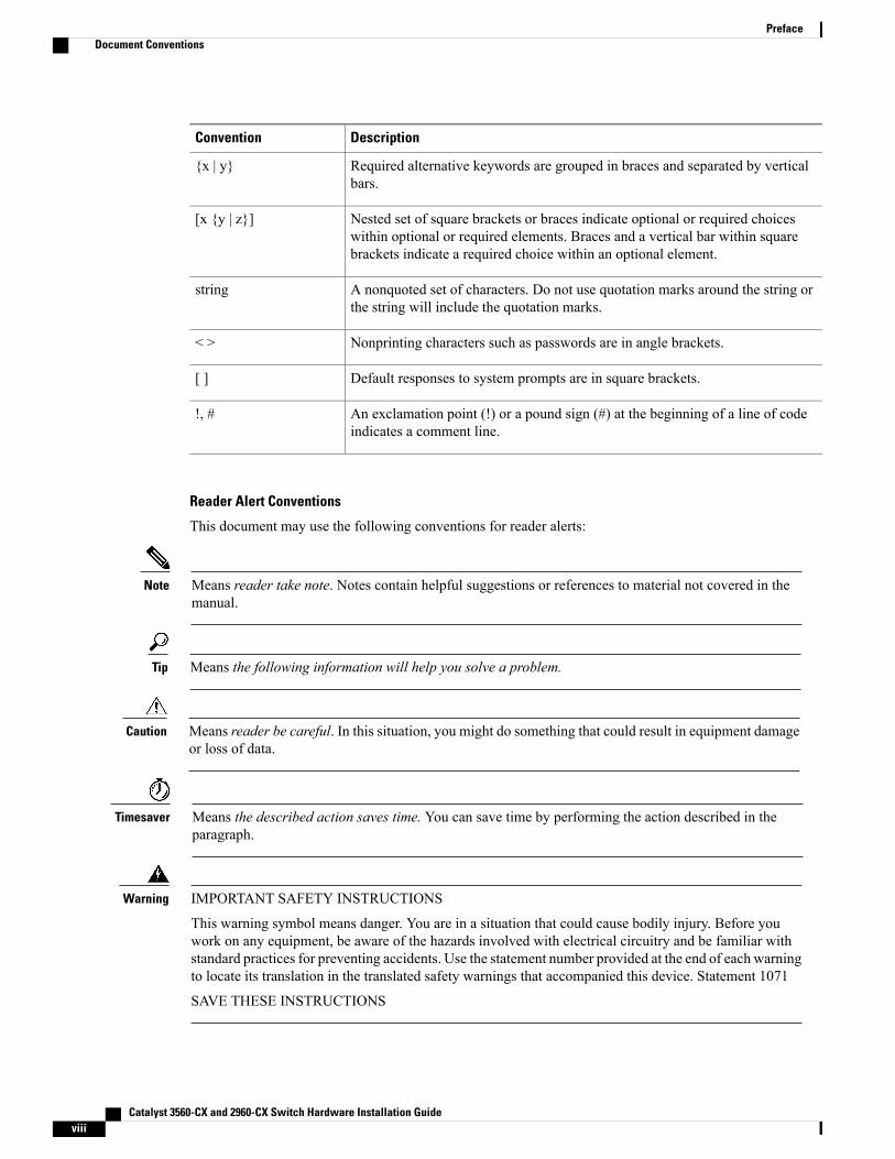
Document ConventionsThis document uses the following conventions:
DescriptionConvention
Both the ^ symbol and Ctrl represent the Control (Ctrl) key on a keyboard. Forexample, the key combination^D orCtrl-Dmeans that you hold down the Controlkey while you press the D key. (Keys are indicated in capital letters but are notcase sensitive.)
^ or Ctrl
Commands and keywords and user-entered text appear in bold font.bold font
Document titles, new or emphasized terms, and arguments for which you supplyvalues are in italic font.
Italic font
Terminal sessions and information the system displays appear in courier font.Courier font
Bold Courier font indicates text that the user must enter.Bold Courier font
Elements in square brackets are optional.[x]
An ellipsis (three consecutive nonbolded periods without spaces) after a syntaxelement indicates that the element can be repeated.
...
A vertical line, called a pipe, indicates a choice within a set of keywords orarguments.
|
Optional alternative keywords are grouped in brackets and separated by verticalbars.
[x | y]
Catalyst 3560-CX and 2960-CX Switch Hardware Installation Guide vii
DescriptionConvention
Required alternative keywords are grouped in braces and separated by verticalbars.
{x | y}
Nested set of square brackets or braces indicate optional or required choiceswithin optional or required elements. Braces and a vertical bar within squarebrackets indicate a required choice within an optional element.
[x {y | z}]
A nonquoted set of characters. Do not use quotation marks around the string orthe string will include the quotation marks.
string
Nonprinting characters such as passwords are in angle brackets.< >
Default responses to system prompts are in square brackets.[ ]
An exclamation point (!) or a pound sign (#) at the beginning of a line of codeindicates a comment line.
!, #
Reader Alert Conventions
This document may use the following conventions for reader alerts:
Means reader take note. Notes contain helpful suggestions or references to material not covered in themanual.
Note
Means the following information will help you solve a problem.Tip
Means reader be careful. In this situation, you might do something that could result in equipment damageor loss of data.
Caution
Means the described action saves time. You can save time by performing the action described in theparagraph.
Timesaver
IMPORTANT SAFETY INSTRUCTIONS
This warning symbol means danger. You are in a situation that could cause bodily injury. Before youwork on any equipment, be aware of the hazards involved with electrical circuitry and be familiar withstandard practices for preventing accidents. Use the statement number provided at the end of each warningto locate its translation in the translated safety warnings that accompanied this device. Statement 1071
SAVE THESE INSTRUCTIONS
Warning
Catalyst 3560-CX and 2960-CX Switch Hardware Installation Guideviii
PrefaceDocument Conventions
Related Documentation
Before installing or upgrading the switch, refer to the release notes.Note
• Catalyst 3560-CX and Catalyst 2960-CX switch documentation at these URLs:
• http://www.cisco.com/c/en/us/support/switches/catalyst-3560-cx-series-switches/tsd-products-support-series-home.html
• http://www.cisco.com/c/en/us/support/switches/catalyst-2960-cx-series-switches/tsd-products-support-series-home.html
• Cisco SFP and SFP+modules documentation, including compatibility matrixes, located at:http://www.cisco.com/en/US/products/hw/modules/ps5455/tsd_products_support_series_home.html
• Cisco Validated Designs documents at this URL:http://www.cisco.com/go/designzone
Obtaining Documentation and Submitting a Service RequestFor information on obtaining documentation, submitting a service request, and gathering additional information,see the monthlyWhat's New in Cisco Product Documentation, which also lists all new and revised Ciscotechnical documentation, at:
http://www.cisco.com/c/en/us/td/docs/general/whatsnew/whatsnew.html
Subscribe to theWhat's New in Cisco Product Documentation as a Really Simple Syndication (RSS) feedand set content to be delivered directly to your desktop using a reader application. The RSS feeds are a freeservice and Cisco currently supports RSS version 2.0.
Catalyst 3560-CX and 2960-CX Switch Hardware Installation Guide ix
PrefaceRelated Documentation

Catalyst 3560-CX and 2960-CX Switch Hardware Installation Guidex
PrefaceObtaining Documentation and Submitting a Service Request
C H A P T E R 1Product Overview
The Catalyst 3560-CX and 2960-CX switches are Ethernet switches to which you can connect devices suchas Cisco IP Phones, Cisco Wireless Access Points, workstations, and other network devices such as servers,routers, and other switches.
You can deploy these switches outside of the traditional wiring closet environment, such as in officeworkspaces, hotel rooms, slot machines, kiosks, and classrooms. The switch is suitable for deploymentswhere there are space and power constraints (access to power outlets).
See the switch software configuration guide for deployment examples.
This chapter contains these topics:
• Switch Models, page 1
• Front Panel, page 2
• Rear Panel, page 9
• Management Options, page 13
• Network Configurations, page 14
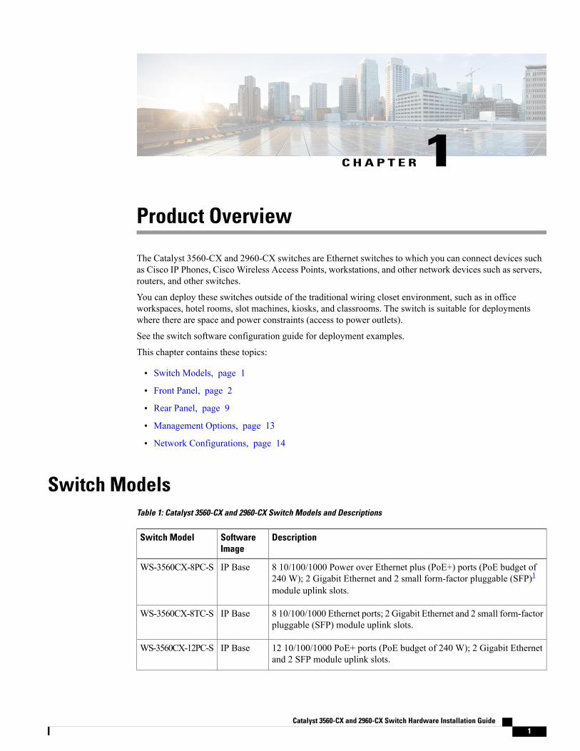
Switch ModelsTable 1: Catalyst 3560-CX and 2960-CX Switch Models and Descriptions
DescriptionSoftwareImage
Switch Model
8 10/100/1000 Power over Ethernet plus (PoE+) ports (PoE budget of240 W); 2 Gigabit Ethernet and 2 small form-factor pluggable (SFP)1
module uplink slots.
IP BaseWS-3560CX-8PC-S
8 10/100/1000 Ethernet ports; 2 Gigabit Ethernet and 2 small form-factorpluggable (SFP) module uplink slots.
IP BaseWS-3560CX-8TC-S
12 10/100/1000 PoE+ ports (PoE budget of 240 W); 2 Gigabit Ethernetand 2 SFP module uplink slots.
IP BaseWS-3560CX-12PC-S
Catalyst 3560-CX and 2960-CX Switch Hardware Installation Guide 1
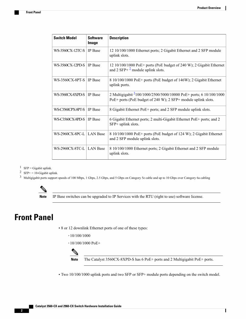
DescriptionSoftwareImage
Switch Model
12 10/100/1000 Ethernet ports; 2 Gigabit Ethernet and 2 SFP moduleuplink slots.
IP BaseWS-3560CX-12TC-S
12 10/100/1000 PoE+ ports (PoE budget of 240 W); 2 Gigabit Ethernetand 2 SFP+ 2 module uplink slots.
IP BaseWS-3560CX-12PD-S
8 10/100/1000 PoE+ ports (PoE budget of 146W); 2 Gigabit Ethernetuplink ports.
IP BaseWS-3560CX-8PT-S
2 Multigigabit 3100/1000/2500/5000/10000 PoE+ ports; 6 10/100/1000PoE+ ports (PoE budget of 240 W); 2 SFP+ module uplink slots.
IP BaseWS-3560CX-8XPD-S
8 Gigabit Ethernet PoE+ ports; and 2 SFP module uplink slots.IP BaseWS-C3560CPX-8PT-S
6 Gigabit Ethernet ports; 2 multi-Gigabit Ethernet PoE+ ports; and 2SFP+ uplink slots.
IP BaseWS-C3560CX-8PD-S
8 10/100/1000 PoE+ ports (PoE budget of 124 W); 2 Gigabit Ethernetand 2 SFP module uplink slots.
LAN BaseWS-2960CX-8PC-L
8 10/100/1000 Ethernet ports; 2 Gigabit Ethernet and 2 SFP moduleuplink slots.
LAN BaseWS-2960CX-8TC-L
1 SFP = Gigabit uplink.2 SFP+ = 10-Gigabit uplink.3 Multigigabit ports support speeds of 100 Mbps, 1 Gbps, 2.5 Gbps, and 5 Gbps on Category 5e cable and up to 10 Gbps over Category 6a cabling
IP Base switches can be upgraded to IP Services with the RTU (right to use) software license.Note
Front Panel• 8 or 12 downlink Ethernet ports of one of these types:
◦10/100/1000
◦10/100/1000 PoE+
The Catalyst 3560CX-8XPD-S has 6 PoE+ ports and 2 Multigigabit PoE+ ports.Note
• Two 10/100/1000 uplink ports and two SFP or SFP+ module ports depending on the switch model.
Catalyst 3560-CX and 2960-CX Switch Hardware Installation Guide2
Product OverviewFront Panel
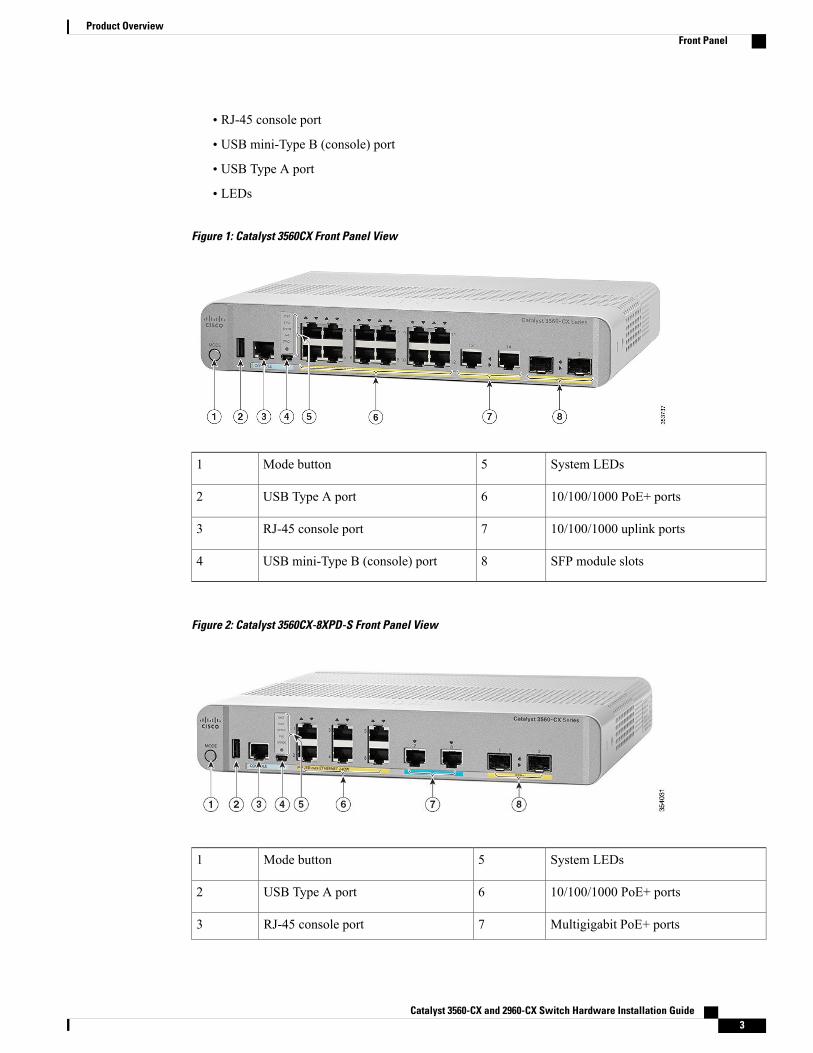
• RJ-45 console port
• USB mini-Type B (console) port
• USB Type A port
• LEDs
Figure 1: Catalyst 3560CX Front Panel View
System LEDs5Mode button1
10/100/1000 PoE+ ports6USB Type A port2
10/100/1000 uplink ports7RJ-45 console port3
SFP module slots8USB mini-Type B (console) port4
Figure 2: Catalyst 3560CX-8XPD-S Front Panel View
System LEDs5Mode button1
10/100/1000 PoE+ ports6USB Type A port2
Multigigabit PoE+ ports7RJ-45 console port3
Catalyst 3560-CX and 2960-CX Switch Hardware Installation Guide 3
Product OverviewFront Panel
SFP module slots8USB mini-Type B (console) port4
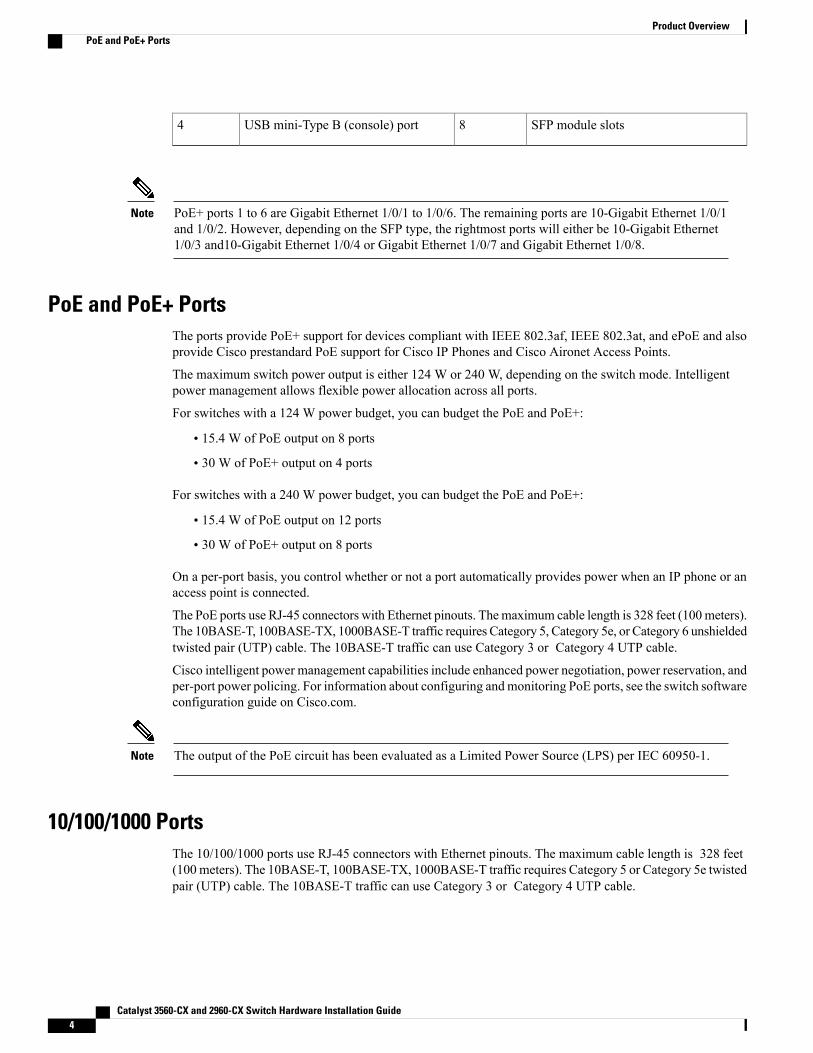
PoE+ ports 1 to 6 are Gigabit Ethernet 1/0/1 to 1/0/6. The remaining ports are 10-Gigabit Ethernet 1/0/1and 1/0/2. However, depending on the SFP type, the rightmost ports will either be 10-Gigabit Ethernet1/0/3 and10-Gigabit Ethernet 1/0/4 or Gigabit Ethernet 1/0/7 and Gigabit Ethernet 1/0/8.
Note
PoE and PoE+ PortsThe ports provide PoE+ support for devices compliant with IEEE 802.3af, IEEE 802.3at, and ePoE and alsoprovide Cisco prestandard PoE support for Cisco IP Phones and Cisco Aironet Access Points.
The maximum switch power output is either 124 W or 240 W, depending on the switch mode. Intelligentpower management allows flexible power allocation across all ports.
For switches with a 124 W power budget, you can budget the PoE and PoE+:
• 15.4 W of PoE output on 8 ports
• 30 W of PoE+ output on 4 ports
For switches with a 240 W power budget, you can budget the PoE and PoE+:
• 15.4 W of PoE output on 12 ports
• 30 W of PoE+ output on 8 ports
On a per-port basis, you control whether or not a port automatically provides power when an IP phone or anaccess point is connected.
The PoE ports use RJ-45 connectors with Ethernet pinouts. Themaximum cable length is 328 feet (100meters).The 10BASE-T, 100BASE-TX, 1000BASE-T traffic requires Category 5, Category 5e, or Category 6 unshieldedtwisted pair (UTP) cable. The 10BASE-T traffic can use Category 3 or Category 4 UTP cable.
Cisco intelligent power management capabilities include enhanced power negotiation, power reservation, andper-port power policing. For information about configuring andmonitoring PoE ports, see the switch softwareconfiguration guide on Cisco.com.
The output of the PoE circuit has been evaluated as a Limited Power Source (LPS) per IEC 60950-1.Note
10/100/1000 PortsThe 10/100/1000 ports use RJ-45 connectors with Ethernet pinouts. The maximum cable length is 328 feet(100 meters). The 10BASE-T, 100BASE-TX, 1000BASE-T traffic requires Category 5 or Category 5e twistedpair (UTP) cable. The 10BASE-T traffic can use Category 3 or Category 4 UTP cable.
Catalyst 3560-CX and 2960-CX Switch Hardware Installation Guide4
Product OverviewPoE and PoE+ Ports
Multigigabit portsThe Multigigabit ports can be configured to auto-negotiate multiple speeds on switch ports, and support 100Mbps, 1 Gbps, 2.5 Gbps, and 5 Gbps speeds on Category5e cables, and up to 10 Gbps over Category6 andCategory 6A cables.
The Multigigabit ports support PoE and PoE+ for all the supported speeds and cable types. The followingtable lists the cable types and speed.
10G5G2.5G1G100MbpsCable Type
N/AYesYesYesYesCategory5E
Yes (55meters)YesYesYesYesCategory6
YesYesYesYesYesCategory6A
Management PortsThe management ports connect the switch to a PC running Microsoft Windows or to a terminal server.
• RJ-45 console port (EIA/TIA-232). The RJ-45 console port connection uses an RJ-45-to-DB-9 femalecable.
• USB mini-Type B console port (5-pin connector).
If you use the USB mini-Type B console port, the Cisco Windows USB device driver must be installed onany PC connected to the console port (for operation with Microsoft Windows). Mac OS X or Linux do notrequire special drivers.
The 4-pin mini-Type B connector resembles the 5-pin mini-Type B connectors. They are not compatible. Useonly the 5-pin mini-Type B.
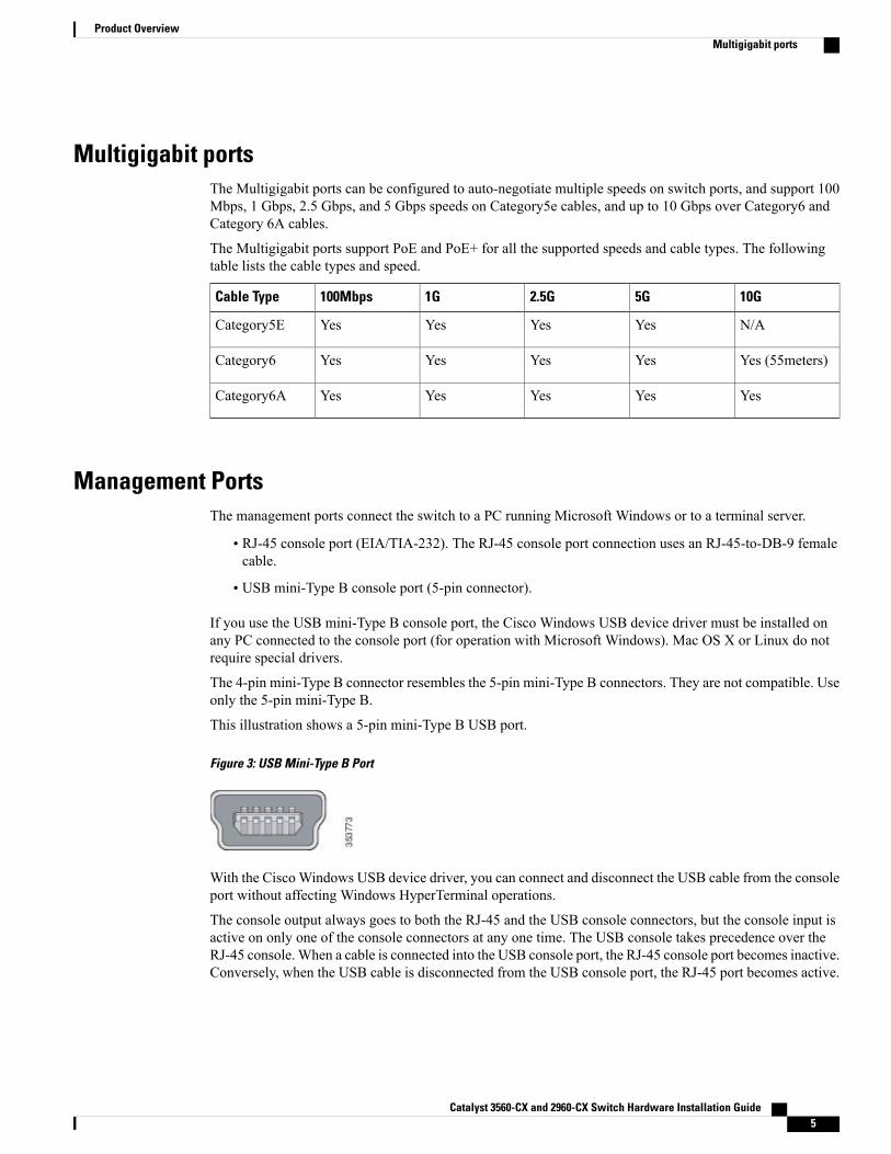
This illustration shows a 5-pin mini-Type B USB port.
Figure 3: USB Mini-Type B Port
With the CiscoWindows USB device driver, you can connect and disconnect the USB cable from the consoleport without affecting Windows HyperTerminal operations.
The console output always goes to both the RJ-45 and the USB console connectors, but the console input isactive on only one of the console connectors at any one time. The USB console takes precedence over theRJ-45 console.When a cable is connected into the USB console port, the RJ-45 console port becomes inactive.Conversely, when the USB cable is disconnected from the USB console port, the RJ-45 port becomes active.
Catalyst 3560-CX and 2960-CX Switch Hardware Installation Guide 5
Product OverviewMultigigabit ports
You can use the command-line interface (CLI) to configure an inactivity timeout which reactivates the RJ-45console if the USB console has been activated and no input activity has occurred on the USB console for aspecified time.
After the USB console deactivates due to inactivity, you cannot use the CLI to reactivate it. Disconnect andreconnect the USB cable to reactivate the USB console. For information on using the CLI to configure theUSB console interface, see the software guide.
SFP and SFP+ Module SlotsThe switch has either two 1-Gigabit SFP or 10-Gigabit SFP+ module slots. The slots marked SFP+ supportboth SFP and SFP+ modules. The SFP slots support only the SFP modules.
For Cisco SFP and SFP+ modules documentation, including compatibility matrixes, refer to this URL: http://www.cisco.com/en/US/products/hw/modules/ps5455/products_device_support_tables_list.html
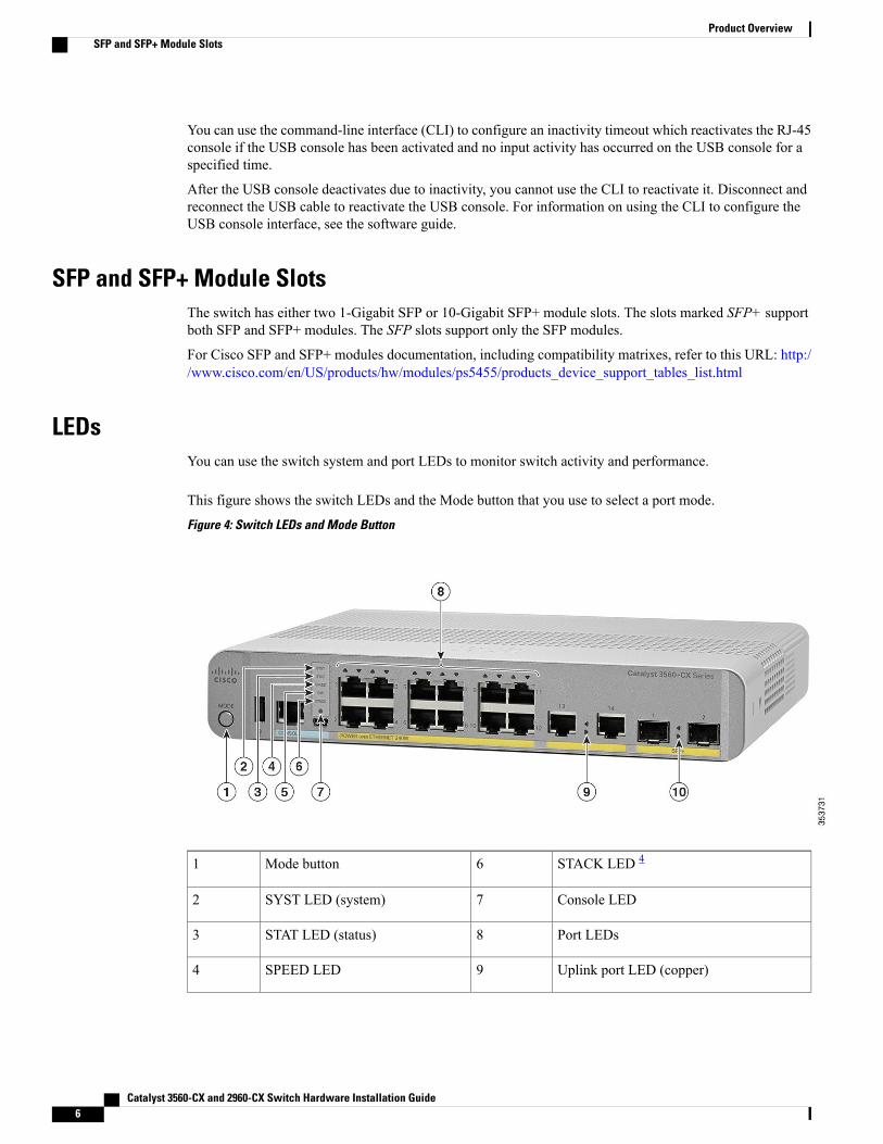
LEDsYou can use the switch system and port LEDs to monitor switch activity and performance.
This figure shows the switch LEDs and the Mode button that you use to select a port mode.
Figure 4: Switch LEDs and Mode Button
STACK LED 46Mode button1
Console LED7SYST LED (system)2
Port LEDs8STAT LED (status)3
Uplink port LED (copper)9SPEED LED4
Catalyst 3560-CX and 2960-CX Switch Hardware Installation Guide6
Product OverviewSFP and SFP+ Module Slots
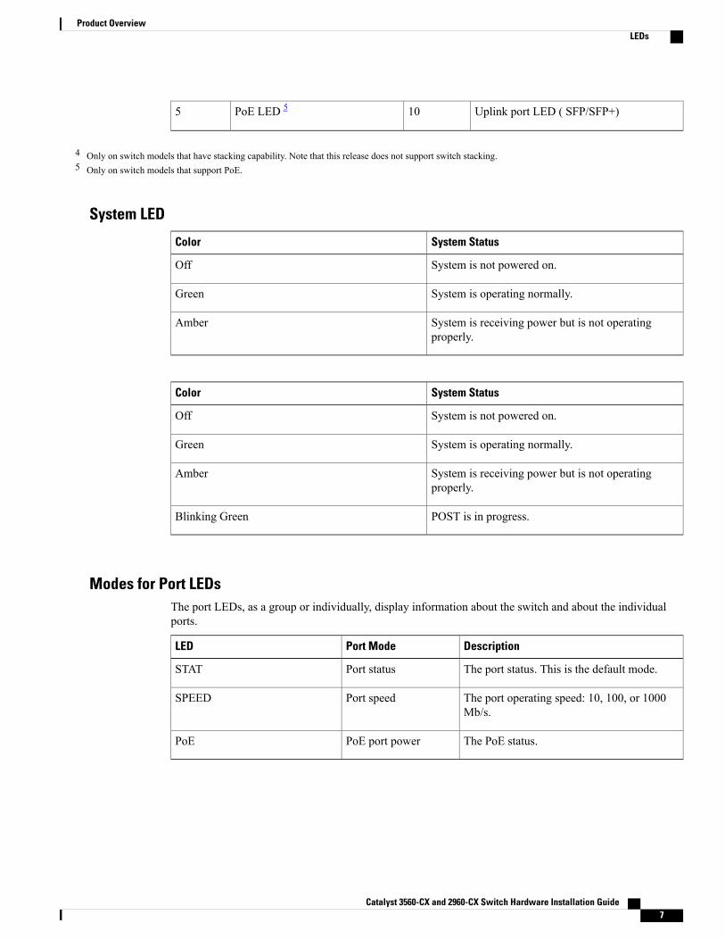
Uplink port LED ( SFP/SFP+)10PoE LED 55
4 Only on switch models that have stacking capability. Note that this release does not support switch stacking.5 Only on switch models that support PoE.
System LED
System StatusColor
System is not powered on.Off
System is operating normally.Green
System is receiving power but is not operatingproperly.
Amber
System StatusColor
System is not powered on.Off
System is operating normally.Green
System is receiving power but is not operatingproperly.
Amber
POST is in progress.Blinking Green
Modes for Port LEDsThe port LEDs, as a group or individually, display information about the switch and about the individualports.
DescriptionPort ModeLED
The port status. This is the default mode.Port statusSTAT
The port operating speed: 10, 100, or 1000Mb/s.
Port speedSPEED
The PoE status.PoE port powerPoE
Catalyst 3560-CX and 2960-CX Switch Hardware Installation Guide 7
Product OverviewLEDs
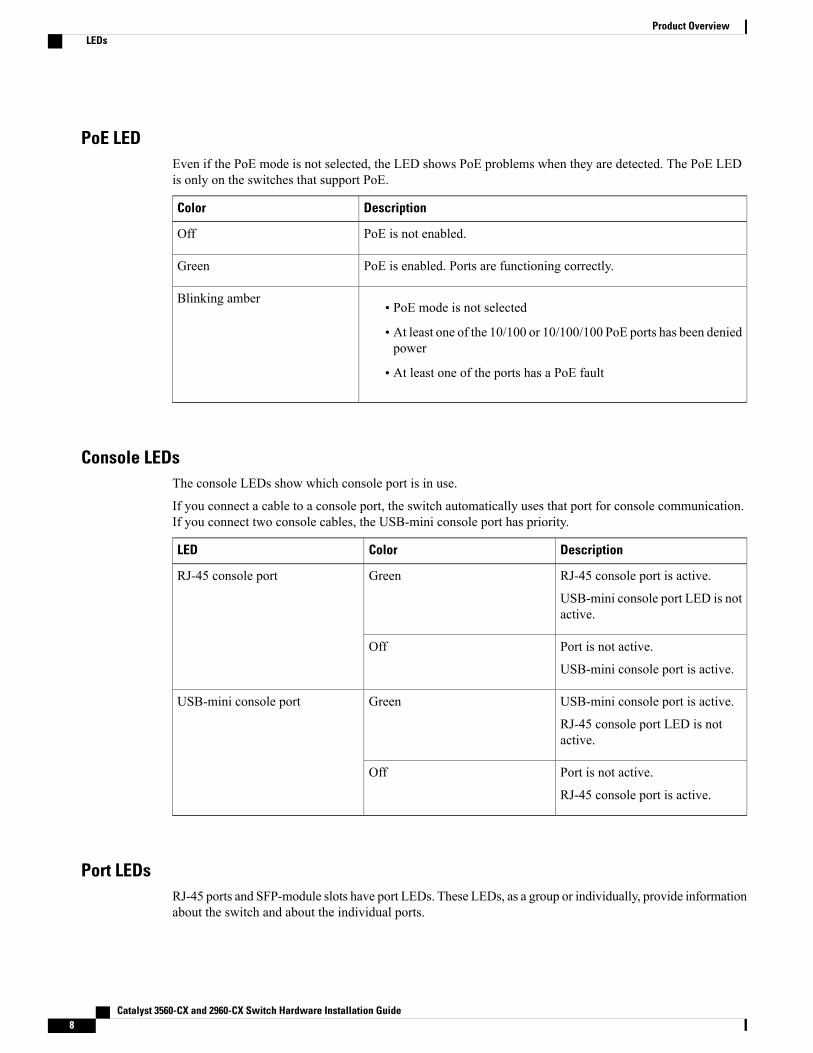
PoE LEDEven if the PoE mode is not selected, the LED shows PoE problems when they are detected. The PoE LEDis only on the switches that support PoE.
DescriptionColor
PoE is not enabled.Off
PoE is enabled. Ports are functioning correctly.Green
• PoE mode is not selected
• At least one of the 10/100 or 10/100/100 PoE ports has been deniedpower
• At least one of the ports has a PoE fault
Blinking amber
Console LEDsThe console LEDs show which console port is in use.
If you connect a cable to a console port, the switch automatically uses that port for console communication.If you connect two console cables, the USB-mini console port has priority.
DescriptionColorLED
RJ-45 console port is active.
USB-mini console port LED is notactive.
GreenRJ-45 console port
Port is not active.
USB-mini console port is active.
Off
USB-mini console port is active.
RJ-45 console port LED is notactive.
GreenUSB-mini console port
Port is not active.
RJ-45 console port is active.
Off
Port LEDsRJ-45 ports and SFP-module slots have port LEDs. These LEDs, as a group or individually, provide informationabout the switch and about the individual ports.
Catalyst 3560-CX and 2960-CX Switch Hardware Installation Guide8
Product OverviewLEDs
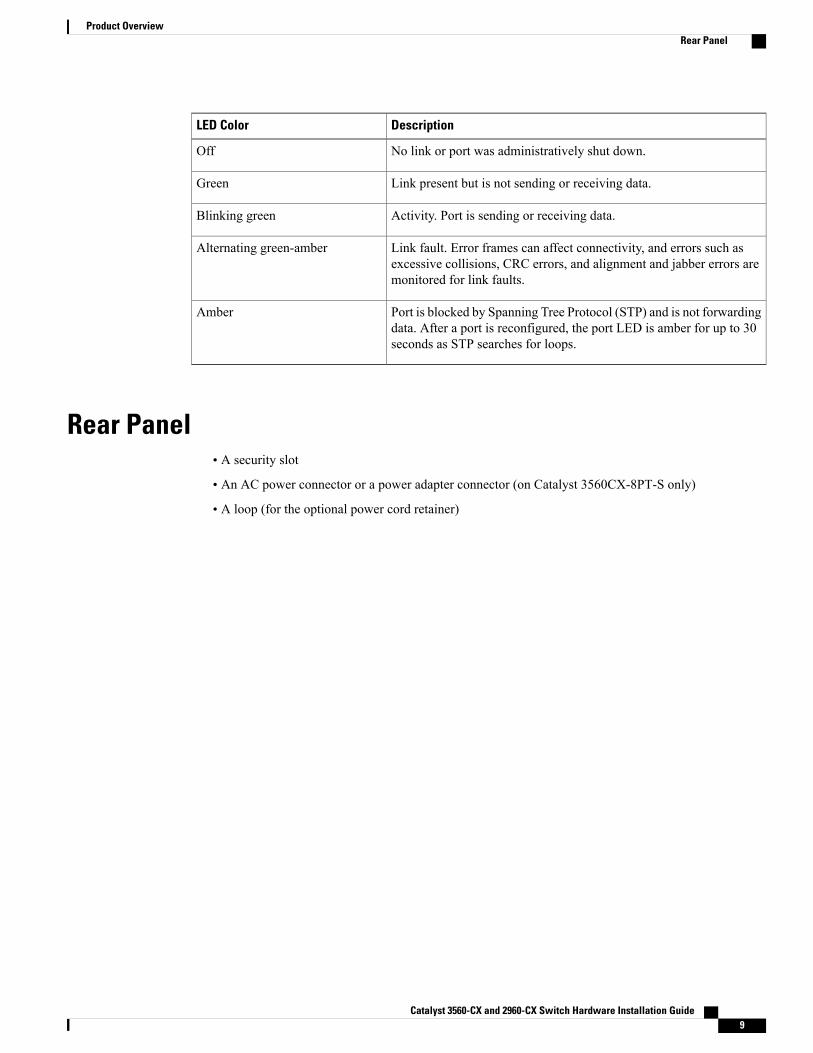
DescriptionLED Color
No link or port was administratively shut down.Off
Link present but is not sending or receiving data.Green
Activity. Port is sending or receiving data.Blinking green
Link fault. Error frames can affect connectivity, and errors such asexcessive collisions, CRC errors, and alignment and jabber errors aremonitored for link faults.
Alternating green-amber
Port is blocked by Spanning Tree Protocol (STP) and is not forwardingdata. After a port is reconfigured, the port LED is amber for up to 30seconds as STP searches for loops.
Amber
Rear Panel• A security slot
• An AC power connector or a power adapter connector (on Catalyst 3560CX-8PT-S only)
• A loop (for the optional power cord retainer)
Catalyst 3560-CX and 2960-CX Switch Hardware Installation Guide 9
Product OverviewRear Panel
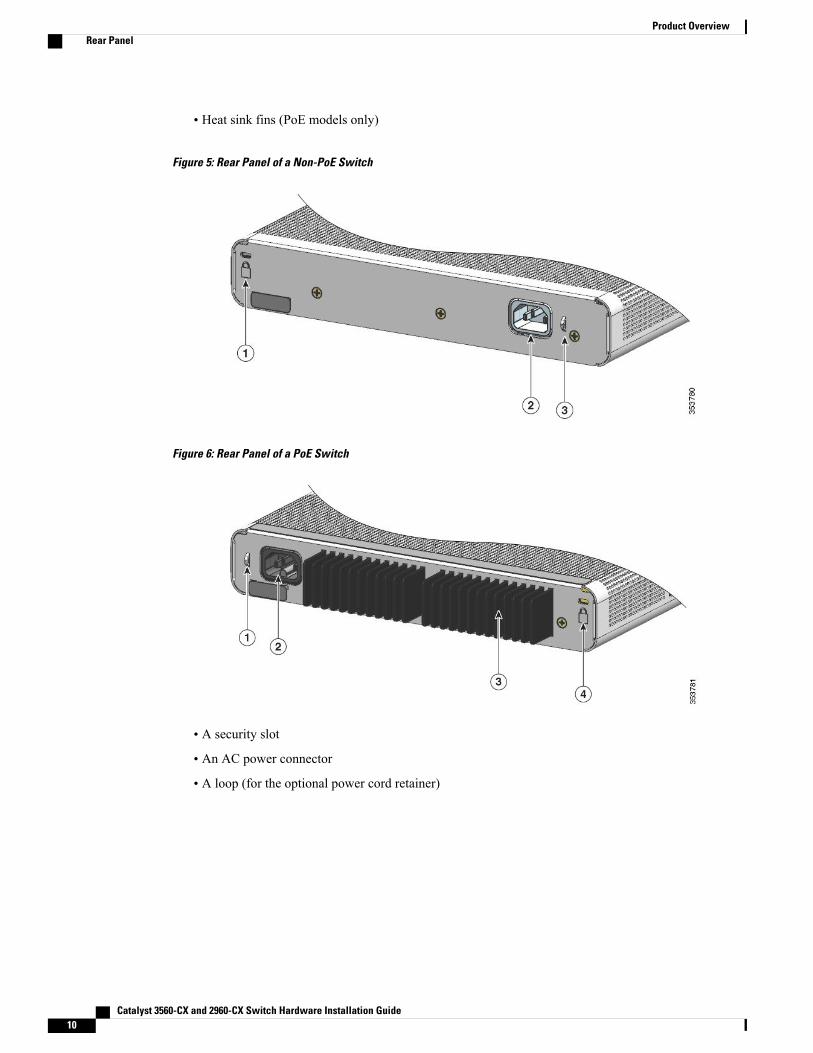
• Heat sink fins (PoE models only)
Figure 5: Rear Panel of a Non-PoE Switch
Figure 6: Rear Panel of a PoE Switch
• A security slot
• An AC power connector
• A loop (for the optional power cord retainer)
Catalyst 3560-CX and 2960-CX Switch Hardware Installation Guide10
Product OverviewRear Panel
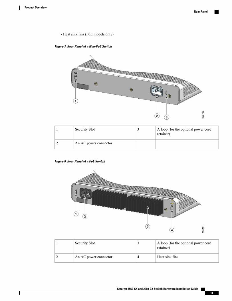
• Heat sink fins (PoE models only)
Figure 7: Rear Panel of a Non-PoE Switch
A loop (for the optional power cordretainer)
3Security Slot1
An AC power connector2
Figure 8: Rear Panel of a PoE Switch
A loop (for the optional power cordretainer)
3Security Slot1
Heat sink fins4An AC power connector2
Catalyst 3560-CX and 2960-CX Switch Hardware Installation Guide 11
Product OverviewRear Panel
Internal Power SupplyAll the switches except Catalyst 3560CX-8PT-S are powered through their internal power supplies. Theinternal power supply is an autoranging unit that supports input voltages between 100 and 240 VAC. Plugthe AC power cord into the AC power connector and into an AC power outlet.
All the switches are powered through their internal power supplies. The internal power supply is an autorangingunit that supports input voltages between 100 and 240 VAC (max of 90V to 264V). The AC frequency rangeof the power supply is 50Hz~60Hz. Plug the AC power cord into the AC power connector and into an ACpower outlet.
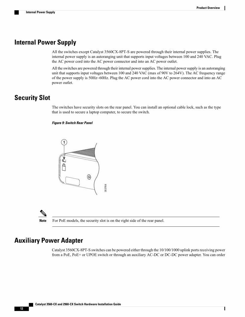
Security SlotThe switches have security slots on the rear panel. You can install an optional cable lock, such as the typethat is used to secure a laptop computer, to secure the switch.
Figure 9: Switch Rear Panel
For PoE models, the security slot is on the right side of the rear panel.Note
Auxiliary Power AdapterCatalyst 3560CX-8PT-S switches can be powered either through the 10/100/1000 uplink ports receiving powerfrom a PoE, PoE+ or UPOE switch or through an auxiliary AC-DC or DC-DC power adapter. You can order
Catalyst 3560-CX and 2960-CX Switch Hardware Installation Guide12
Product OverviewInternal Power Supply
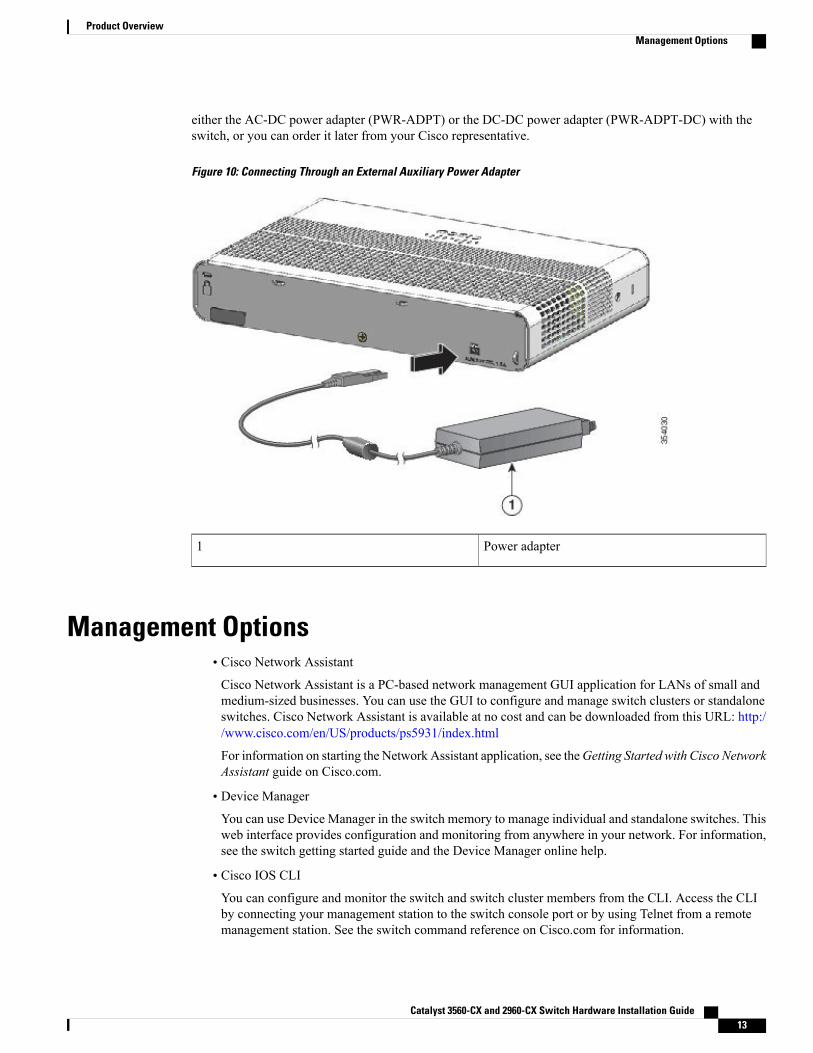
either the AC-DC power adapter (PWR-ADPT) or the DC-DC power adapter (PWR-ADPT-DC) with theswitch, or you can order it later from your Cisco representative.
Figure 10: Connecting Through an External Auxiliary Power Adapter
Power adapter1
Management Options• Cisco Network AssistantCisco Network Assistant is a PC-based network management GUI application for LANs of small andmedium-sized businesses. You can use the GUI to configure and manage switch clusters or standaloneswitches. Cisco Network Assistant is available at no cost and can be downloaded from this URL: http://www.cisco.com/en/US/products/ps5931/index.html
For information on starting the Network Assistant application, see theGetting Started with Cisco NetworkAssistant guide on Cisco.com.
• Device Manager
You can use Device Manager in the switch memory to manage individual and standalone switches. Thisweb interface provides configuration and monitoring from anywhere in your network. For information,see the switch getting started guide and the Device Manager online help.
• Cisco IOS CLIYou can configure and monitor the switch and switch cluster members from the CLI. Access the CLIby connecting your management station to the switch console port or by using Telnet from a remotemanagement station. See the switch command reference on Cisco.com for information.
Catalyst 3560-CX and 2960-CX Switch Hardware Installation Guide 13
Product OverviewManagement Options
• Cisco Prime InfrastructureCisco Prime Infrastructure combines the wireless functionality of Cisco Prime Network Control System(NCS) and the wired functionality of Cisco Prime LANManagement Solution (LMS), with applicationperformance monitoring and troubleshooting capabilities of Cisco Prime Assurance Manager. For moreinformation, see the Cisco Prime Infrastructure documentation on Cisco.com.
• Catalyst Smart OperationsThe Smart Install feature provides a single point of management (director) in a network. You can use itto provide a zero touch image and configuration upgrade of newly deployed switches and image andconfiguration downloads for any client switches. For information, see the Cisco Smart InstallConfiguration Guide on Cisco.com.
Auto Smartports macros dynamically configure ports based on the device type detected on the port.When the switch detects a new device, it applies the appropriate Auto Smartports macro on the port.For information about configuring Auto Smartports, see the switch software configuration guide onCisco.com.
Network ConfigurationsSee the switch software configuration guide on Cisco.com for network configuration concepts and examplesof using the switch to create dedicated network segments and interconnecting the segments through FastEthernet and Gigabit Ethernet connections.
Catalyst 3560-CX and 2960-CX Switch Hardware Installation Guide14
Product OverviewNetwork Configurations
C H A P T E R 2Switch Installation
For initial switch setup, assigning the switch IP address, and powering on information, see the switch gettingstarted guide on Cisco.com.
This chapter contains these topics:
• Warnings, page 15
• Box Contents, page 17
• Tools and Equipment, page 18
• Installation Guidelines, page 18
• Verifying Switch Operation, page 19
• Mounting the Switch, page 20
• Attaching the Adapter Bracket to the Switch (Optional), page 38
• Installing the Power Cord Retainer (Optional), page 39
• Installing the Cable Guard (Optional), page 42
• Installing SFP and SFP+Modules, page 46
• 10/100/1000 PoE and PoE+Port Connections, page 47
• 10/100/1000 Port Connections, page 49
• Where to Go Next, page 49
WarningsThis section includes the warning statements relating to basic installation. Read this section before you startthe installation procedure.
Before working on equipment that is connected to power lines, remove jewelry (including rings, necklaces,and watches). Metal objects will heat up when connected to power and ground and can cause serious burnsor weld the metal object to the terminals. Statement 43
Warning
Catalyst 3560-CX and 2960-CX Switch Hardware Installation Guide 15
Read the wall-mounting instructions carefully before beginning installation. Failure to use the correcthardware or to follow the correct procedures could result in a hazardous situation to people and damageto the system. Statement 378
Warning
Do not work on the system or connect or disconnect cables during periods of lightning activity. Statement1001
Warning
Read the installation instructions before connecting the system to the power source. Statement 1004Warning
To prevent bodily injury when mounting or servicing this unit in a rack, you must take special precautionsto ensure that the system remains stable. The following guidelines are provided to ensure your safety:
Warning
• This unit should be mounted at the bottom of the rack if it is the only unit in the rack.
• When mounting this unit in a partially filled rack, load the rack from the bottom to the top with theheaviest component at the bottom of the rack.
• If the rack is provided with stabilizing devices, install the stabilizers before mounting or servicingthe unit in the rack.
Statement 1006
Class 1 laser product. Statement 1008Warning
This equipment must be grounded. Never defeat the ground conductor or operate the equipment in theabsence of a suitably installed ground conductor. Contact the appropriate electrical inspection authorityor an electrician if you are uncertain that suitable grounding is available. Statement 1024
Warning
Ultimate disposal of this product should be handled according to all national laws and regulations.Statement 1040
Warning
For connections outside the building where the equipment is installed, the following ports must be connectedthrough an approved network termination unit with integral circuit protection: 10/100/1000 Ethernet.Statement 1044
Warning
Catalyst 3560-CX and 2960-CX Switch Hardware Installation Guide16
Switch InstallationWarnings
To prevent the system from overheating, do not operate it in an area that exceeds the maximumrecommended ambient temperature of: <113°F (45°C). Statement 1047
Warning
The maximum operating temperature is 40°C for Catalyst 3560CX-12PD-S and C3560CX-8XPD-Sswitches and 45°C for all the other switch models. However, for WS-C3560CX-8XPD-S, the maximumoperating temperature will be 35°C when installed inverted and under fully loaded conditions (maximumPoE and 10G SFP+ transceivers installed).
Note
This warning symbol means danger. You are in a situation that could cause bodily injury. Before youwork on any equipment, be aware of the hazards involved with electrical circuitry and be familiar withstandard practices for preventing accidents. Use the statement number provided at the end of each warningto locate its translation in the translated safety warnings that accompanied this device. Statement 1071
Warning
Voltages that present a shock hazard may exist on Power over Ethernet (PoE) circuits if interconnectionsare made using uninsulated exposed metal contacts, conductors, or terminals. Avoid using suchinterconnection methods, unless the exposed metal parts are located within a restricted access locationand users and service people who are authorized within the restricted access location are made aware ofthe hazard. A restricted access area can be accessed only through the use of a special tool, lock and keyor other means of security. Statement 1072
Warning
No user-serviceable parts inside. Do not open. Statement 1073Warning
Installation of the equipment must comply with local and national electrical codes. Statement 1074Warning
To prevent airflow restriction, allow clearance around the ventilation openings to be at least: 3 inches (7.6cm). Statement 1076
Warning
Hot surface. Statement 1079Warning
Box ContentsThe switch getting started guide describes the box contents. If any item is missing or damaged, contact yourCisco representative or reseller for support.
Catalyst 3560-CX and 2960-CX Switch Hardware Installation Guide 17
Switch InstallationBox Contents
Tools and EquipmentObtain these necessary tools and equipment:
• Number-2 Phillips screwdriver
• Drill with a #27 drill bit (0.144-inch [3.7 mm])
Installation GuidelinesWhen determining where to install the switch, verify that these guidelines are met:
• Clearance to front panels is such that the LEDs can be easily read.
• Power cord reaches from the power outlet to the connector on the switch.
• Cabling is away from sources of electrical noise, such as radios, power lines, and fluorescent lightingfixtures.
• Temperature around the unit does not exceed 113°F (45°C). If the switch is installed in a closed ormultirack assembly, the temperature around it might be greater than normal room temperature.
The Catalyst 3560CX-12PD-S and C3560CX-8XPD-S switches have a maximumoperating temperature of 40°C. All the other switches have a maximum operatingtemperature of 45°C. However, for WS-C3560CX-8XPD-S, the maximum operatingtemperature will be 35°C when installed inverted and under fully loaded conditions(maximum PoE and 10G SFP+ transceivers installed).
Note
When using these products with the GLC-T SFP module, the thermal limitations are asfollows:
Note
• At sea level, table top installation temperature should not exceed 35°C and invertedinstallation temperature should not exceed 30°C
• At 5000 feet, table top installation temperature should not exceed 30°C and invertedinstallation temperature should not exceed 25°C
• At 10000 feet, table top installation temperature should not exceed 25°C andinverted installation temperature should not exceed 20°C
• Humidity around the switch does not exceed 95 percent.
• Altitude at the installation site is not greater than 10,000 feet.
• Airflow around the switch and through the vents must be unrestricted. To avoid any flow blockage, westrongly recommend these guidelines:
◦Allow at least 3 in. (7.6 cm) of clearance from the left and right sides, and the front and rear of theswitch.
Catalyst 3560-CX and 2960-CX Switch Hardware Installation Guide18
Switch InstallationTools and Equipment
◦If you are installing the switch upright, allow at least 1.75 in. (4 cm) of clearance from the topcover.
◦If you are installing the switch inverted, under a table, allow at least 3 in. (7.6 cm) of clearancefrom the top cover.
◦If you are installing the switch in a rack, allow at least 1RU of empty rack space above each switch.
For Catalyst 3560CX-12PD-S andC3560CX-8XPD-S switches operating at themaximumspecified temperature and fully loaded conditions (with transceivers installed andmaximum PoE), when installed inverted, there should be unrestricted airflow all aroundthe switch (and not just limited to the minimum 3 in. requirement). When installedupright, at least 3 in. of clearance from the top cover is required. When installed in arack, at least 2RU of empty rack space above each switch is required.
Note
• When placing the switch on a flat horizontal surface, we strongly recommend that you attach the rubberfeet to the switch.
• For 10/100/1000 fixed ports, cable lengths from the switch to connected devices can be up to 328 feet(100 meters).
• For cable requirements for SFP module connections, see the “SFP Module Cables, on page 64” section.Each port must match the wave-length specifications on the other end of the cable, and the cable mustnot exceed the minimum cable length.
Verifying Switch OperationBefore you install the switch in a rack, on a wall, or on a table or shelf, power on the switch and verify thatit passes POST.
To power on the switch, do one of the following, depending on your switch model:
• Connect a 10/100/1000 uplink port to a PoE or PoE+ switch.
• Plug the auxiliary power adapter cord into the switch AUX power connector and into an AC poweroutlet.
You can use both the uplink port and the auxiliary power adapter. The switch sharespower from all the available power sources. The total available power to the switch isthe sum of power available from all the power sources minus the power that is lost.
Note
• Plug one end of the AC power cord into the switch AC power connector, and plug the other end into anAC power outlet.
Catalyst 3560-CX and 2960-CX Switch Hardware Installation Guide 19
Switch InstallationVerifying Switch Operation
If you have a Catalyst WS-C3560CX-8PT-S switch that is connected to a Power Source Equipment (PSE)PoE or PoE+ port with ether-channel configuration, do not power on the switch by connecting only one10/100/1000 uplink port to the PSE. Doing so will cause the PSE to detect a port channel misconfigurationwhen the switch tries to boot in low power mode, and hence the port will go into error disabled mode.
For CatalystWS-C3560CX-8PT-S switches, you must connect both uplink ports to the PSE. Alternatively,use the auxiliary power supply.
For more details on Low Power Bootup, see the PoE and PoE Pass-Through Ports on CatalystWS-C3560CX-8PT-S section in theConfiguring PoE chapter of the switch's Software Configuration Guideon Cisco.com.
Note
As the switch powers on, it begins the POST, a series of tests that runs automatically to ensure that the switchfunctions properly. LEDs can blink during the test. POST lasts approximately 1 minute. When the switchbegins POST, the SYST, STAT, and SPEED LEDs turn green. The SYST LED blinks green, and the otherLEDs remain solid green.
When the switch completes POST successfully, the SYST LED remains green. The other LEDs turn off andthen reflect the switch operating status. If a switch fails POST, the SYST LED turns amber.
POST failures are usually fatal. Call Cisco technical support representative if your switch fails POST.
After a successful POST, unplug the power cord from the switch and install the switch in a rack, on a wall,on a table, or on a shelf.
Mounting the Switch
Mounting on a Desk or Shelf Without Mounting Screws
Step 1 Locate the adhesive strip with the rubber feet in the accessory kit.Step 2 Remove the four rubber feet from the adhesive strip, and attach them to the recessed areas at the bottom of the unit. This
prevents the switch from sliding on the desk or shelf.We strongly recommend that you attach the rubber feet. Doing so also helps prevent airflow restriction andoverheating.
Note
• To prevent airflow restriction, allow clearance around the ventilation openings to be at least 3 inches(7.6 cm). Statement 1076
Warning
Step 3 Place the switch on the desk or shelf.
Catalyst 3560-CX and 2960-CX Switch Hardware Installation Guide20
Switch InstallationMounting the Switch
On a Desk, Shelf, or Wall (with Mounting Screws)
Desk- or Shelf-Mounting
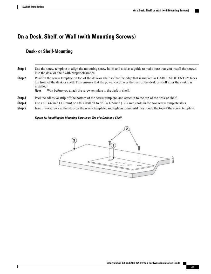
Step 1 Use the screw template to align the mounting screw holes and also as a guide to make sure that you install the screwsinto the desk or shelf with proper clearance.
Step 2 Position the screw template on top of the desk or shelf so that the edge that is marked as CABLE SIDE ENTRY facesthe front of the desk or shelf. This ensures that the power cord faces the rear of the desk or shelf after the switch isinstalled.
Wait before you attach the screw template to the desk or shelf.Note
Step 3 Peel the adhesive strip off the bottom of the screw template, and attach it to the top of the desk or shelf.Step 4 Use a 0.144-inch (3.7 mm) or a #27 drill bit to drill a 1/2-inch (12.7 mm) hole in the two screw template slots.Step 5 Insert two screws in the slots on the screw template, and tighten them until they touch the top of the screw template.
Figure 11: Installing the Mounting Screws on Top of a Desk or a Shelf
Catalyst 3560-CX and 2960-CX Switch Hardware Installation Guide 21
Switch InstallationOn a Desk, Shelf, or Wall (with Mounting Screws)
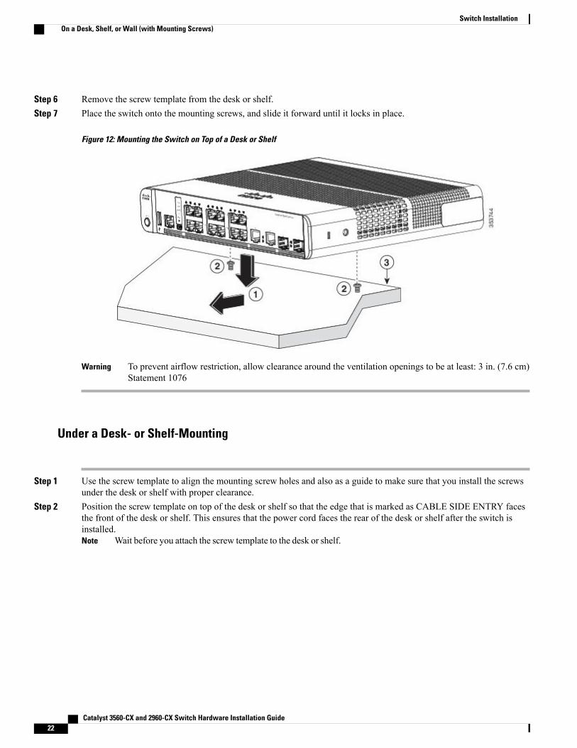
Step 6 Remove the screw template from the desk or shelf.Step 7 Place the switch onto the mounting screws, and slide it forward until it locks in place.
Figure 12: Mounting the Switch on Top of a Desk or Shelf
To prevent airflow restriction, allow clearance around the ventilation openings to be at least: 3 in. (7.6 cm)Statement 1076
Warning
Under a Desk- or Shelf-Mounting
Step 1 Use the screw template to align the mounting screw holes and also as a guide to make sure that you install the screwsunder the desk or shelf with proper clearance.
Step 2 Position the screw template on top of the desk or shelf so that the edge that is marked as CABLE SIDE ENTRY facesthe front of the desk or shelf. This ensures that the power cord faces the rear of the desk or shelf after the switch isinstalled.
Wait before you attach the screw template to the desk or shelf.Note
Catalyst 3560-CX and 2960-CX Switch Hardware Installation Guide22
Switch InstallationOn a Desk, Shelf, or Wall (with Mounting Screws)
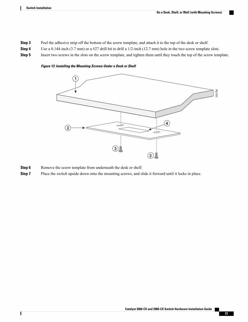
Step 3 Peel the adhesive strip off the bottom of the screw template, and attach it to the top of the desk or shelf.Step 4 Use a 0.144-inch (3.7 mm) or a #27 drill bit to drill a 1/2-inch (12.7 mm) hole in the two screw template slots.Step 5 Insert two screws in the slots on the screw template, and tighten them until they touch the top of the screw template.
Figure 13: Installing the Mounting Screws Under a Desk or Shelf
Step 6 Remove the screw template from underneath the desk or shelf.Step 7 Place the switch upside down onto the mounting screws, and slide it forward until it locks in place.
Catalyst 3560-CX and 2960-CX Switch Hardware Installation Guide 23
Switch InstallationOn a Desk, Shelf, or Wall (with Mounting Screws)
To prevent airflow restriction, allow clearance around the ventilation openings to be at least: 3 in. (7.6 cm)Statement 1076
Warning
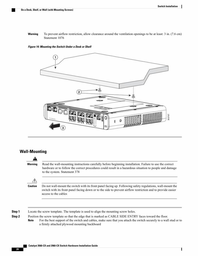
Figure 14: Mounting the Switch Under a Desk or Shelf
Wall-Mounting
Read the wall-mounting instructions carefully before beginning installation. Failure to use the correcthardware or to follow the correct procedures could result in a hazardous situation to people and damageto the system. Statement 378
Warning
Do not wall-mount the switch with its front panel facing up. Following safety regulations, wall-mount theswitch with its front panel facing down or to the side to prevent airflow restriction and to provide easieraccess to the cables
Caution
Step 1 Locate the screw template. The template is used to align the mounting screw holes.Step 2 Position the screw template so that the edge that is marked as CABLE SIDE ENTRY faces toward the floor.
For the best support of the switch and cables, make sure that you attach the switch securely to a wall stud or toa firmly attached plywood mounting backboard
Note
Catalyst 3560-CX and 2960-CX Switch Hardware Installation Guide24
Switch InstallationOn a Desk, Shelf, or Wall (with Mounting Screws)
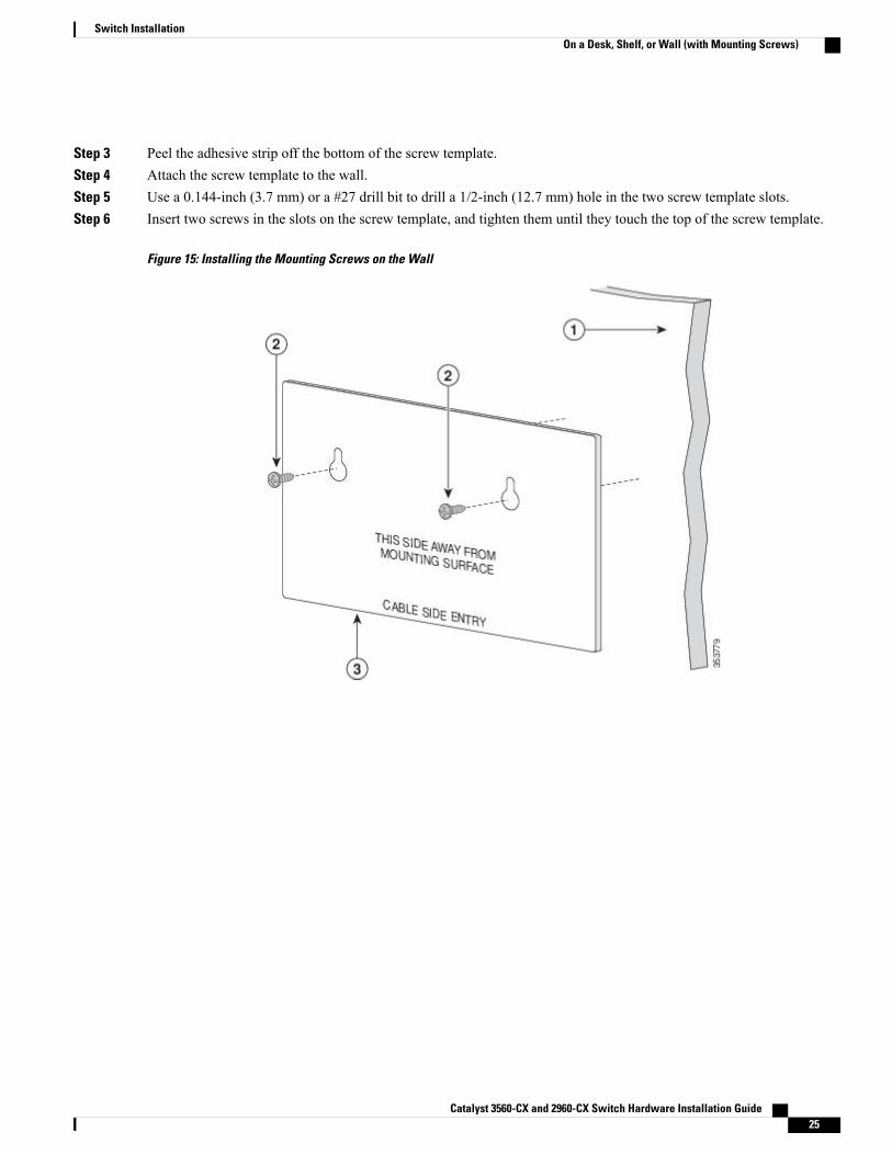
Step 3 Peel the adhesive strip off the bottom of the screw template.Step 4 Attach the screw template to the wall.Step 5 Use a 0.144-inch (3.7 mm) or a #27 drill bit to drill a 1/2-inch (12.7 mm) hole in the two screw template slots.Step 6 Insert two screws in the slots on the screw template, and tighten them until they touch the top of the screw template.
Figure 15: Installing the Mounting Screws on the Wall
Catalyst 3560-CX and 2960-CX Switch Hardware Installation Guide 25
Switch InstallationOn a Desk, Shelf, or Wall (with Mounting Screws)
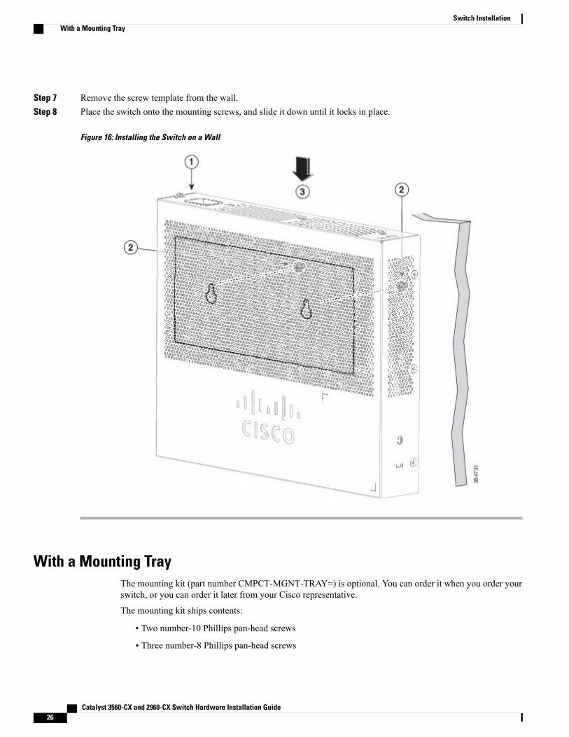
Step 7 Remove the screw template from the wall.Step 8 Place the switch onto the mounting screws, and slide it down until it locks in place.
Figure 16: Installing the Switch on a Wall
With a Mounting TrayThe mounting kit (part number CMPCT-MGNT-TRAY=) is optional. You can order it when you order yourswitch, or you can order it later from your Cisco representative.
The mounting kit ships contents:
• Two number-10 Phillips pan-head screws
• Three number-8 Phillips pan-head screws
Catalyst 3560-CX and 2960-CX Switch Hardware Installation Guide26
Switch InstallationWith a Mounting Tray
• Mounting tray
• Magnet
You can use the mounting tray by itself with mounting screws, or with a magnet.
Mounting Tray with ScrewsYou can use the mounting tray to secure the switch:
• On a desk or shelf
• Under a desk or shelf
• On a wall
Do not wall-mount the switch with its front panel facing up. Following safety regulations, wall-mount theswitch with its front panel facing down or to the side, to allow sufficient airflow and to provide easieraccess to the cables.
Caution
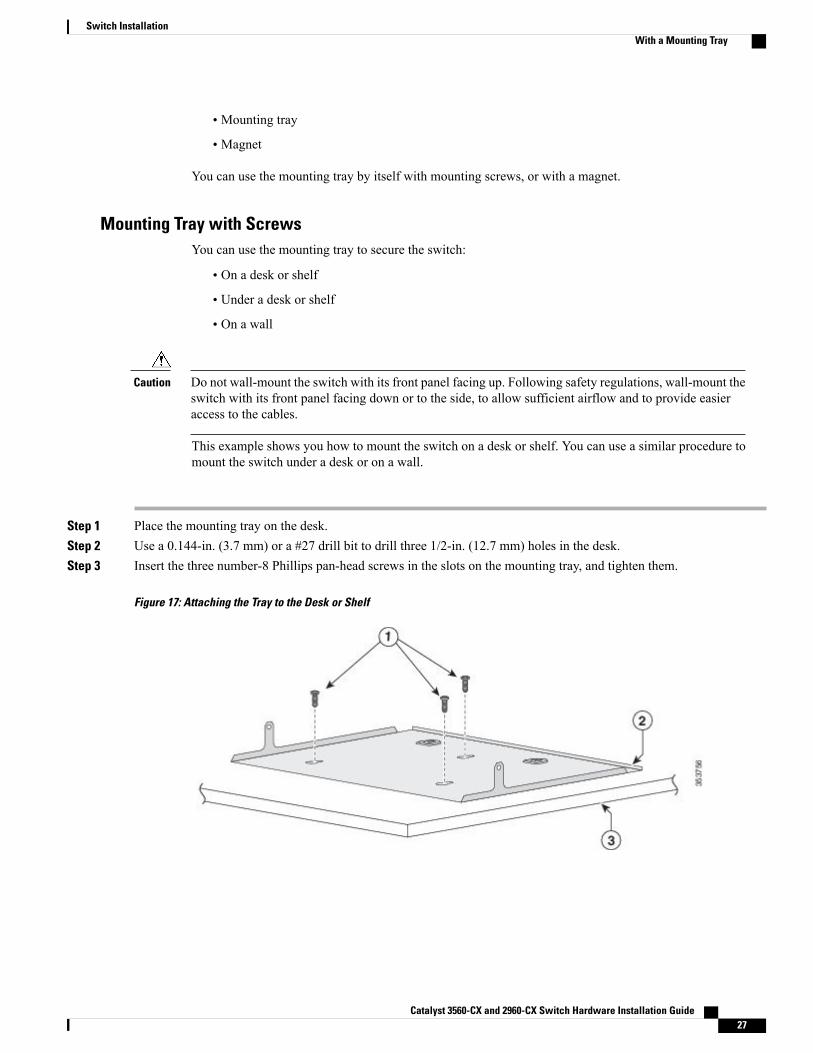
This example shows you how to mount the switch on a desk or shelf. You can use a similar procedure tomount the switch under a desk or on a wall.
Step 1 Place the mounting tray on the desk.Step 2 Use a 0.144-in. (3.7 mm) or a #27 drill bit to drill three 1/2-in. (12.7 mm) holes in the desk.Step 3 Insert the three number-8 Phillips pan-head screws in the slots on the mounting tray, and tighten them.
Figure 17: Attaching the Tray to the Desk or Shelf
Catalyst 3560-CX and 2960-CX Switch Hardware Installation Guide 27
Switch InstallationWith a Mounting Tray
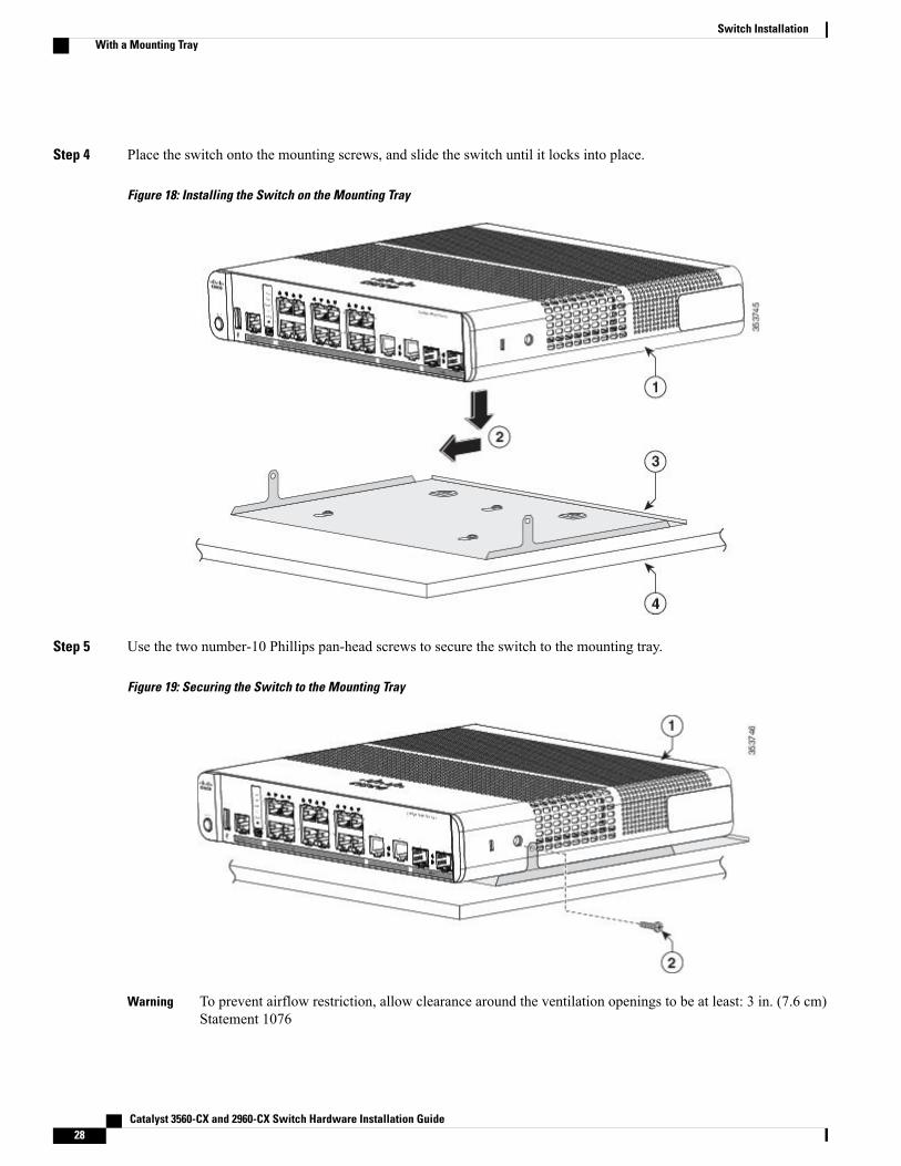
Step 4 Place the switch onto the mounting screws, and slide the switch until it locks into place.
Figure 18: Installing the Switch on the Mounting Tray
Step 5 Use the two number-10 Phillips pan-head screws to secure the switch to the mounting tray.
Figure 19: Securing the Switch to the Mounting Tray
To prevent airflow restriction, allow clearance around the ventilation openings to be at least: 3 in. (7.6 cm)Statement 1076
Warning
Catalyst 3560-CX and 2960-CX Switch Hardware Installation Guide28
Switch InstallationWith a Mounting Tray
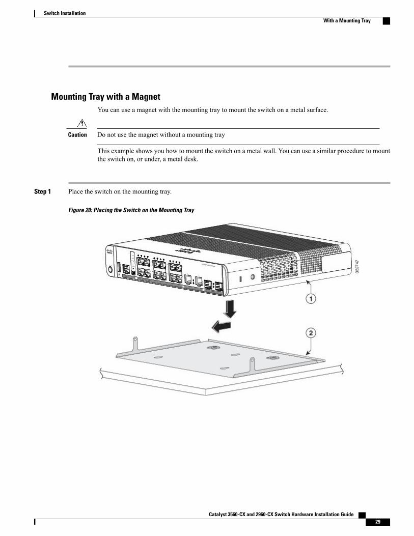
Mounting Tray with a MagnetYou can use a magnet with the mounting tray to mount the switch on a metal surface.
Do not use the magnet without a mounting trayCaution
This example shows you how to mount the switch on a metal wall. You can use a similar procedure to mountthe switch on, or under, a metal desk.
Step 1 Place the switch on the mounting tray.
Figure 20: Placing the Switch on the Mounting Tray
Catalyst 3560-CX and 2960-CX Switch Hardware Installation Guide 29
Switch InstallationWith a Mounting Tray
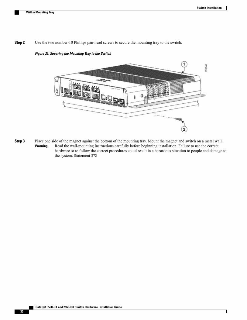
Step 2 Use the two number-10 Phillips pan-head screws to secure the mounting tray to the switch.
Figure 21: Securing the Mounting Tray to the Switch
Step 3 Place one side of the magnet against the bottom of the mounting tray. Mount the magnet and switch on a metal wall.Read the wall-mounting instructions carefully before beginning installation. Failure to use the correcthardware or to follow the correct procedures could result in a hazardous situation to people and damage tothe system. Statement 378
Warning
Catalyst 3560-CX and 2960-CX Switch Hardware Installation Guide30
Switch InstallationWith a Mounting Tray
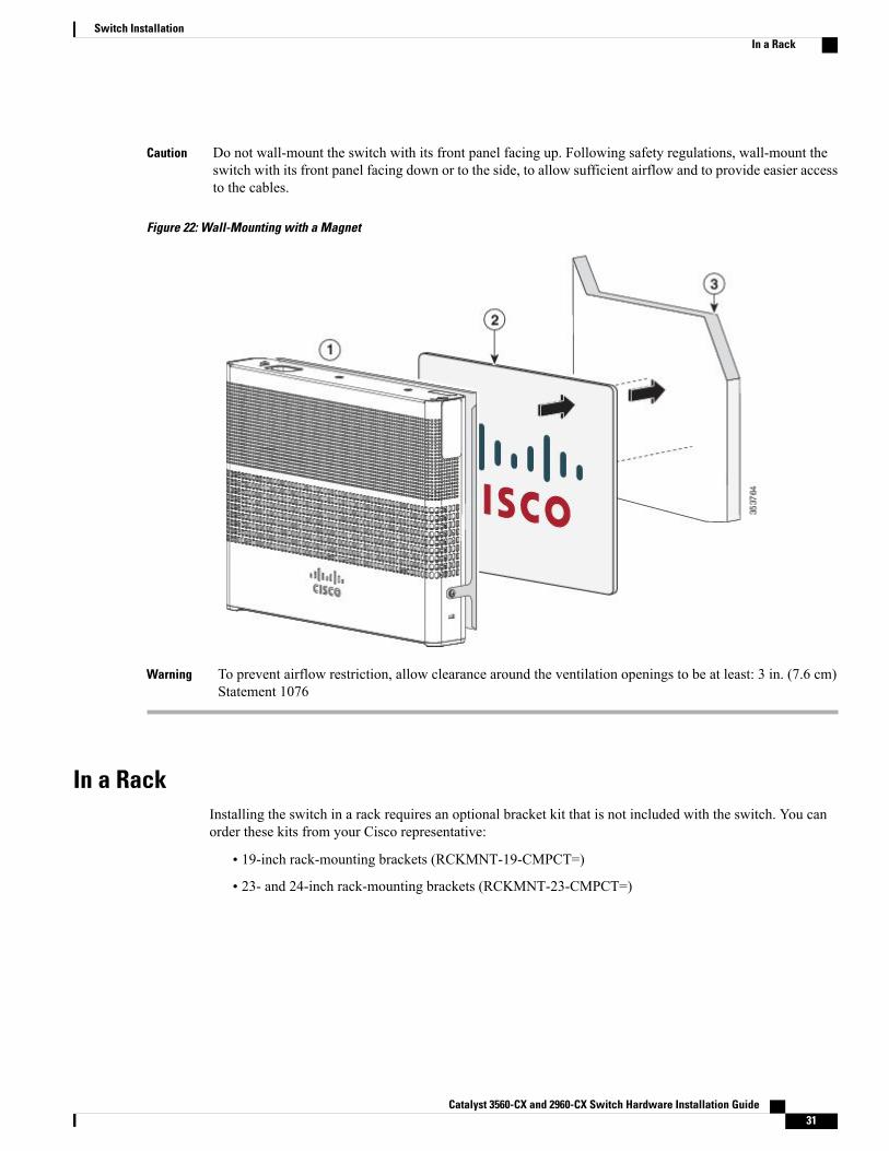
Do not wall-mount the switch with its front panel facing up. Following safety regulations, wall-mount theswitch with its front panel facing down or to the side, to allow sufficient airflow and to provide easier accessto the cables.
Caution
Figure 22: Wall-Mounting with a Magnet
To prevent airflow restriction, allow clearance around the ventilation openings to be at least: 3 in. (7.6 cm)Statement 1076
Warning
In a RackInstalling the switch in a rack requires an optional bracket kit that is not included with the switch. You canorder these kits from your Cisco representative:
• 19-inch rack-mounting brackets (RCKMNT-19-CMPCT=)
• 23- and 24-inch rack-mounting brackets (RCKMNT-23-CMPCT=)
Catalyst 3560-CX and 2960-CX Switch Hardware Installation Guide 31
Switch InstallationIn a Rack
To prevent bodily injury when mounting or servicing this unit in a rack, you must take special precautionsto ensure that the system remains stable. The following guidelines are provided to ensure your safety:
Warning
• This unit should be mounted at the bottom of the rack if it is the only unit in the rack.
• When mounting this unit in a partially filled rack, load the rack from the bottom to the top with theheaviest component at the bottom of the rack.
• If the rack is provided with stabilizing devices, install the stabilizers before mounting or servicingthe unit in the rack.
Statement 1006
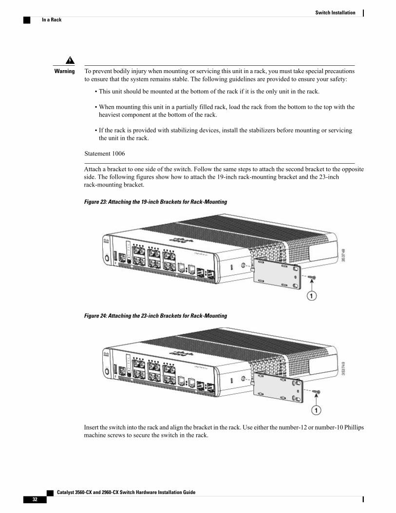
Attach a bracket to one side of the switch. Follow the same steps to attach the second bracket to the oppositeside. The following figures show how to attach the 19-inch rack-mounting bracket and the 23-inchrack-mounting bracket.
Figure 23: Attaching the 19-inch Brackets for Rack-Mounting
Figure 24: Attaching the 23-inch Brackets for Rack-Mounting
Insert the switch into the rack and align the bracket in the rack. Use either the number-12 or number-10 Phillipsmachine screws to secure the switch in the rack.
Catalyst 3560-CX and 2960-CX Switch Hardware Installation Guide32
Switch InstallationIn a Rack
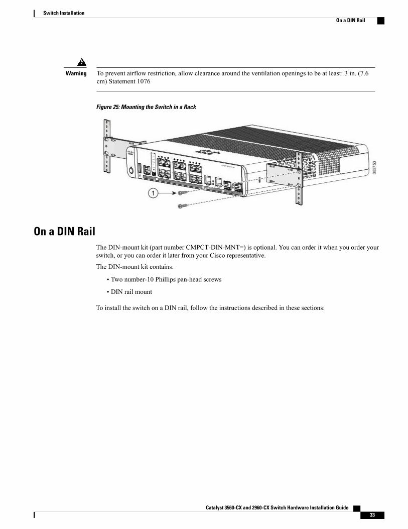
To prevent airflow restriction, allow clearance around the ventilation openings to be at least: 3 in. (7.6cm) Statement 1076
Warning
Figure 25: Mounting the Switch in a Rack
On a DIN RailThe DIN-mount kit (part number CMPCT-DIN-MNT=) is optional. You can order it when you order yourswitch, or you can order it later from your Cisco representative.
The DIN-mount kit contains:
• Two number-10 Phillips pan-head screws
• DIN rail mount
To install the switch on a DIN rail, follow the instructions described in these sections:
Catalyst 3560-CX and 2960-CX Switch Hardware Installation Guide 33
Switch InstallationOn a DIN Rail
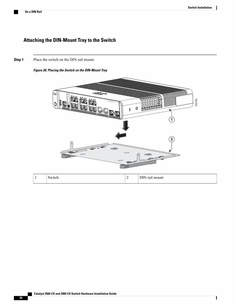
Attaching the DIN-Mount Tray to the Switch
Step 1 Place the switch on the DIN rail mount.
Figure 26: Placing the Switch on the DIN-Mount Tray
DIN rail mount2Switch1
Catalyst 3560-CX and 2960-CX Switch Hardware Installation Guide34
Switch InstallationOn a DIN Rail
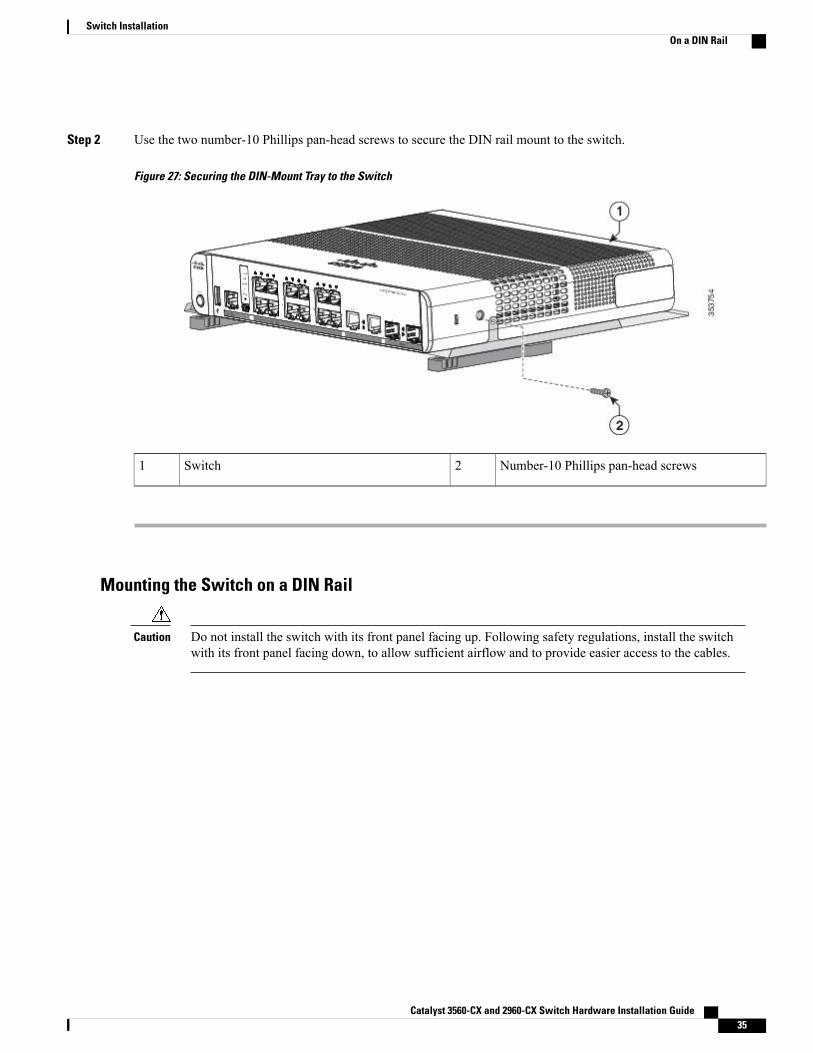
Step 2 Use the two number-10 Phillips pan-head screws to secure the DIN rail mount to the switch.
Figure 27: Securing the DIN-Mount Tray to the Switch
Number-10 Phillips pan-head screws2Switch1
Mounting the Switch on a DIN Rail
Do not install the switch with its front panel facing up. Following safety regulations, install the switchwith its front panel facing down, to allow sufficient airflow and to provide easier access to the cables.
Caution
Catalyst 3560-CX and 2960-CX Switch Hardware Installation Guide 35
Switch InstallationOn a DIN Rail
To prevent airflow restriction, allow clearance around the ventilation openings to be at least: 3 in. (7.6cm) Statement 1076
Warning
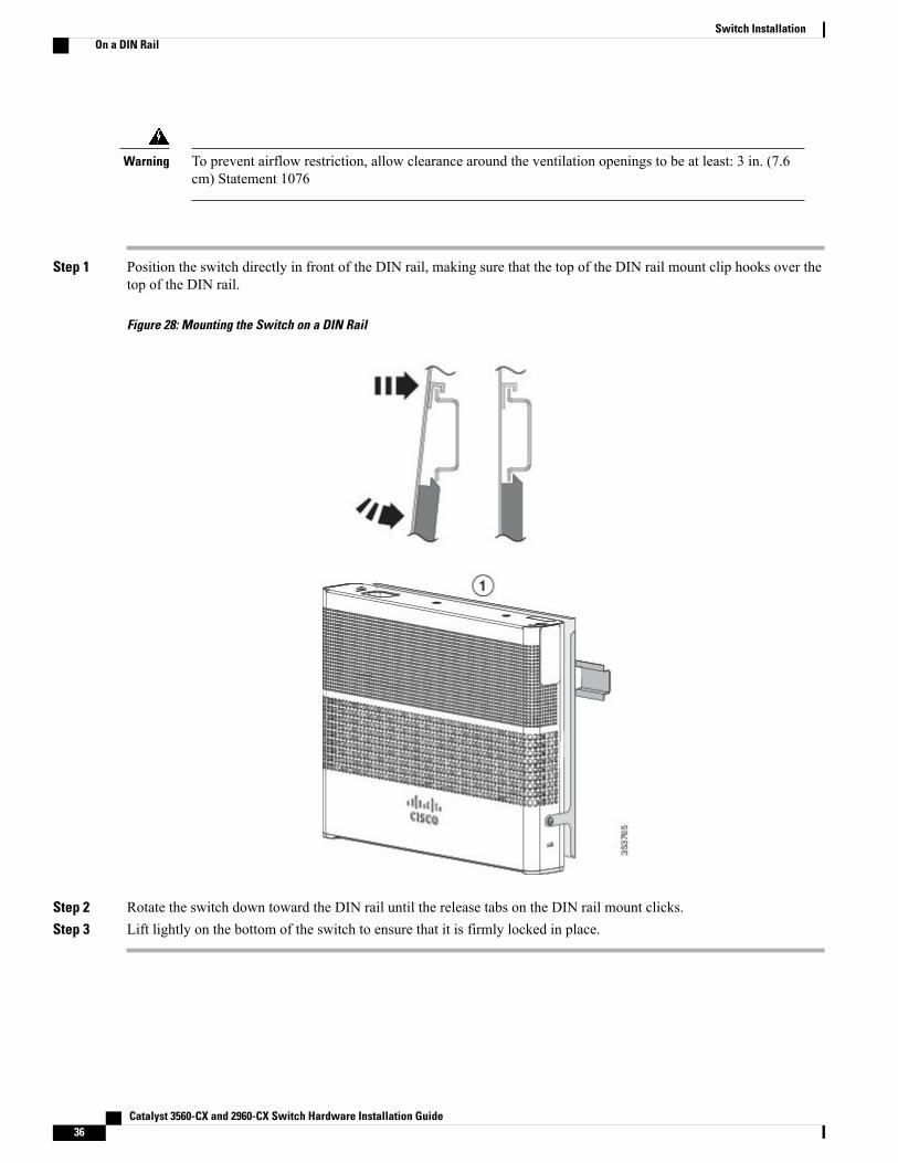
Step 1 Position the switch directly in front of the DIN rail, making sure that the top of the DIN rail mount clip hooks over thetop of the DIN rail.
Figure 28: Mounting the Switch on a DIN Rail
Step 2 Rotate the switch down toward the DIN rail until the release tabs on the DIN rail mount clicks.Step 3 Lift lightly on the bottom of the switch to ensure that it is firmly locked in place.
Catalyst 3560-CX and 2960-CX Switch Hardware Installation Guide36
Switch InstallationOn a DIN Rail
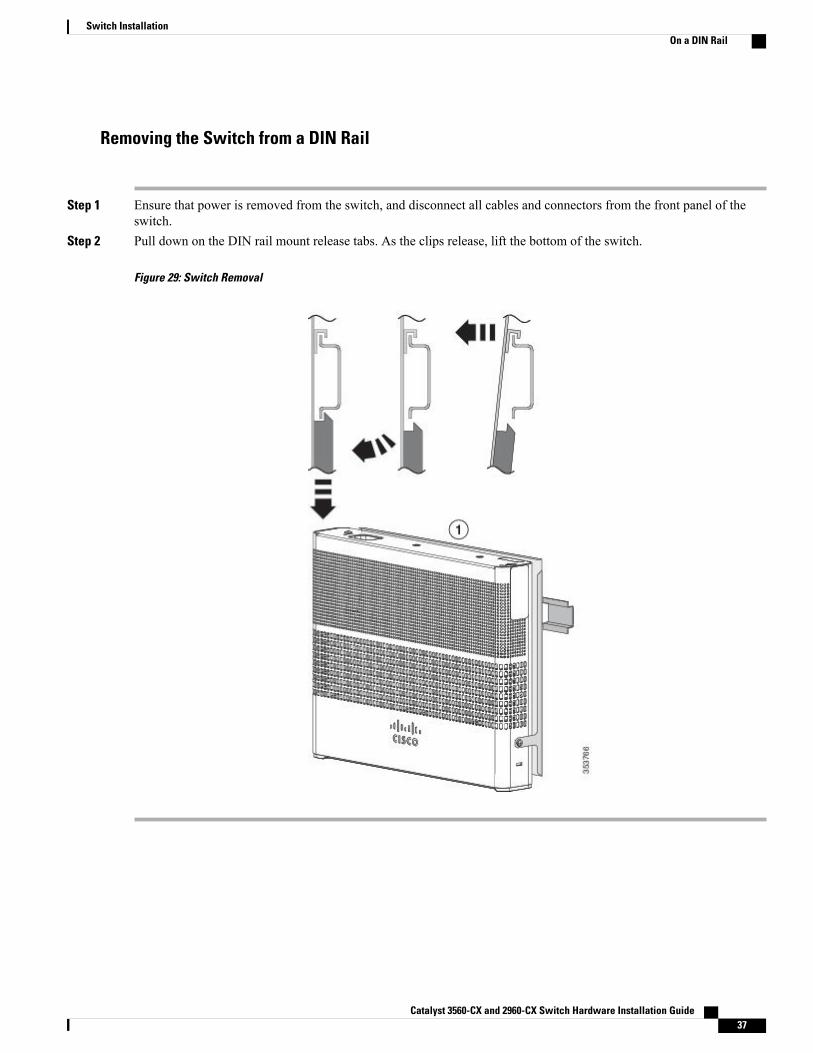
Removing the Switch from a DIN Rail
Step 1 Ensure that power is removed from the switch, and disconnect all cables and connectors from the front panel of theswitch.
Step 2 Pull down on the DIN rail mount release tabs. As the clips release, lift the bottom of the switch.
Figure 29: Switch Removal
Catalyst 3560-CX and 2960-CX Switch Hardware Installation Guide 37
Switch InstallationOn a DIN Rail
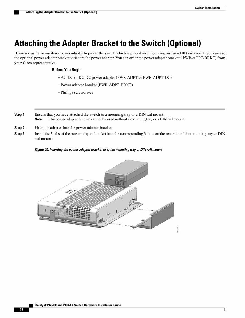
Attaching the Adapter Bracket to the Switch (Optional)If you are using an auxiliary power adapter to power the switch which is placed on a mounting tray or a DIN rail mount, you can usethe optional power adapter bracket to secure the power adapter. You can order the power adapter bracket ( PWR-ADPT-BRKT) fromyour Cisco representative.
Before You Begin
• AC-DC or DC-DC power adapter (PWR-ADPT or PWR-ADPT-DC)
• Power adapter bracket (PWR-ADPT-BRKT)
• Phillips screwdriver
Step 1 Ensure that you have attached the switch to a mounting tray or a DIN rail mount.The power adapter bracket cannot be used without a mounting tray or a DIN rail mount.Note
Step 2 Place the adapter into the power adapter bracket.Step 3 Insert the 3 tabs of the power adapter bracket into the corresponding 3 slots on the rear side of the mounting tray or DIN
rail mount.
Figure 30: Inserting the power adapter bracket in to the mounting tray or DIN rail mount
Catalyst 3560-CX and 2960-CX Switch Hardware Installation Guide38
Switch InstallationAttaching the Adapter Bracket to the Switch (Optional)
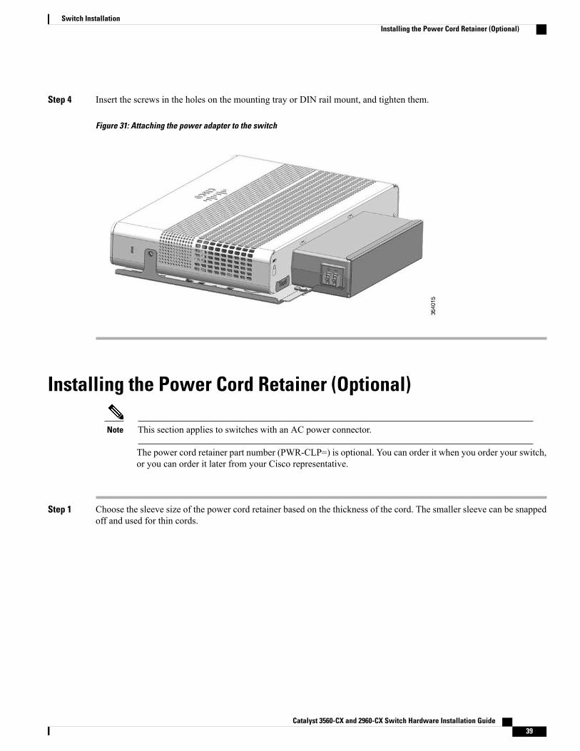
Step 4 Insert the screws in the holes on the mounting tray or DIN rail mount, and tighten them.
Figure 31: Attaching the power adapter to the switch
Installing the Power Cord Retainer (Optional)
This section applies to switches with an AC power connector.Note
The power cord retainer part number (PWR-CLP=) is optional. You can order it when you order your switch,or you can order it later from your Cisco representative.
Step 1 Choose the sleeve size of the power cord retainer based on the thickness of the cord. The smaller sleeve can be snappedoff and used for thin cords.
Catalyst 3560-CX and 2960-CX Switch Hardware Installation Guide 39
Switch InstallationInstalling the Power Cord Retainer (Optional)
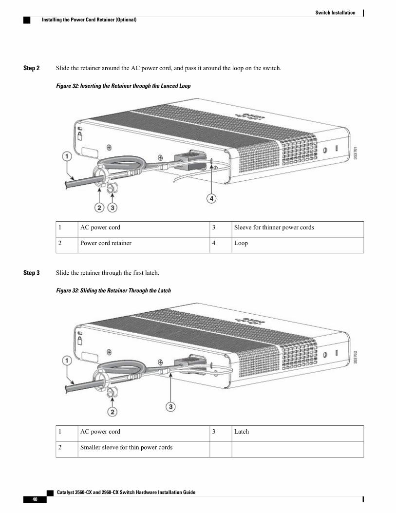
Step 2 Slide the retainer around the AC power cord, and pass it around the loop on the switch.
Figure 32: Inserting the Retainer through the Lanced Loop
Sleeve for thinner power cords3AC power cord1
Loop4Power cord retainer2
Step 3 Slide the retainer through the first latch.
Figure 33: Sliding the Retainer Through the Latch
Latch3AC power cord1
Smaller sleeve for thin power cords2
Catalyst 3560-CX and 2960-CX Switch Hardware Installation Guide40
Switch InstallationInstalling the Power Cord Retainer (Optional)
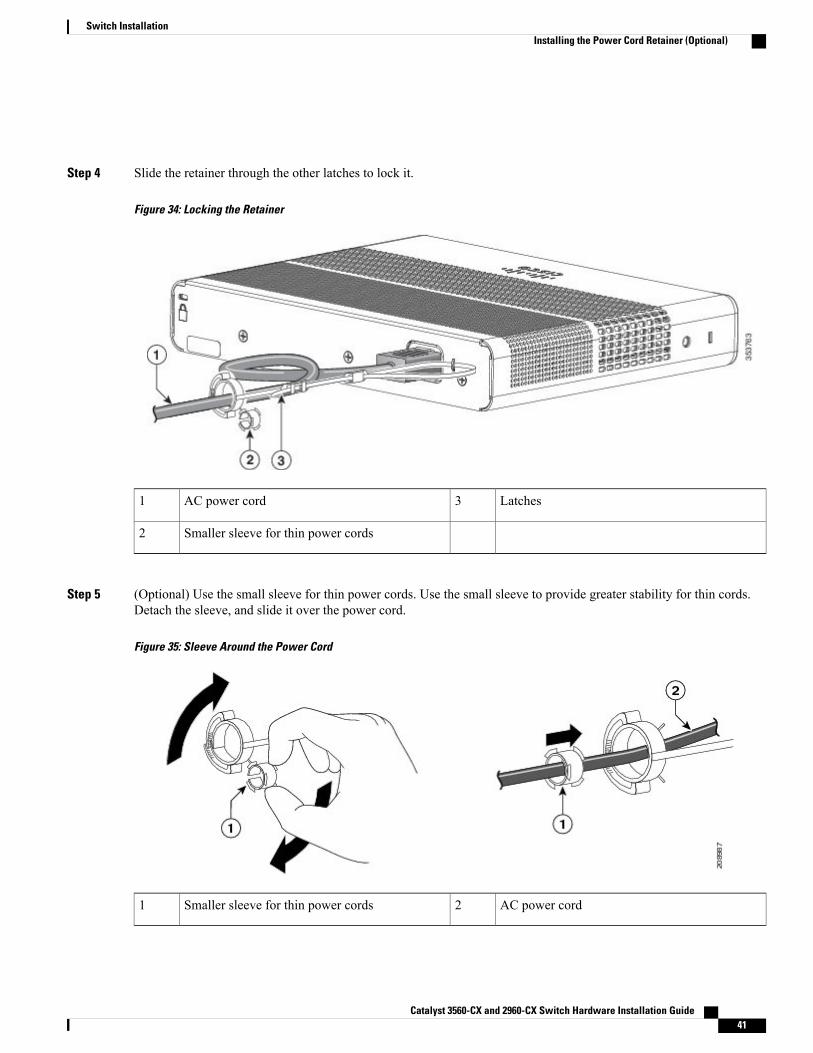
Step 4 Slide the retainer through the other latches to lock it.
Figure 34: Locking the Retainer
Latches3AC power cord1
Smaller sleeve for thin power cords2
Step 5 (Optional) Use the small sleeve for thin power cords. Use the small sleeve to provide greater stability for thin cords.Detach the sleeve, and slide it over the power cord.
Figure 35: Sleeve Around the Power Cord
AC power cord2Smaller sleeve for thin power cords1
Catalyst 3560-CX and 2960-CX Switch Hardware Installation Guide 41
Switch InstallationInstalling the Power Cord Retainer (Optional)
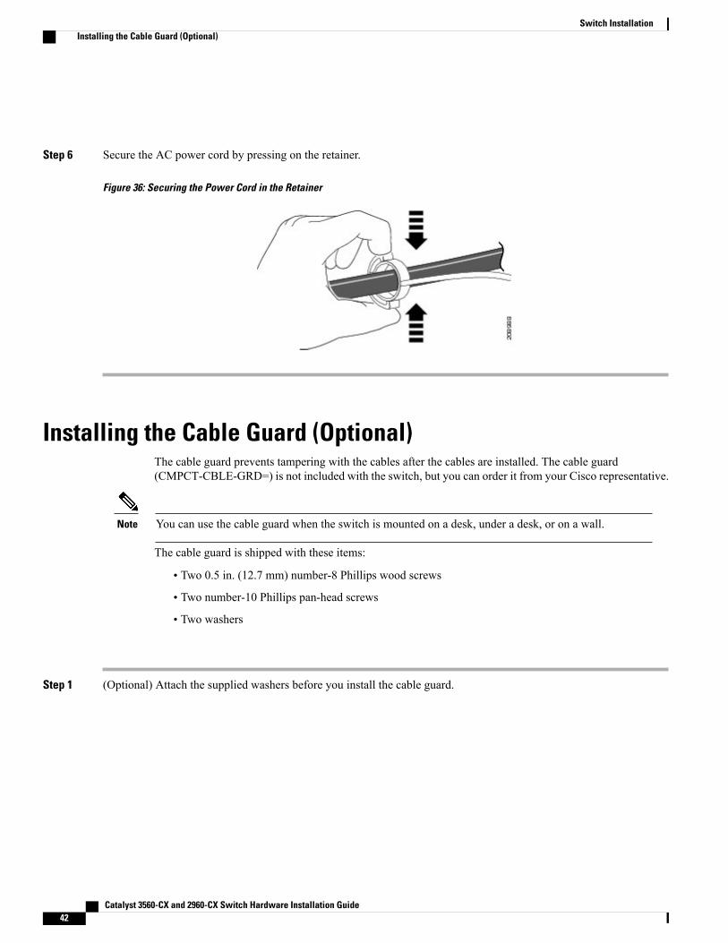
Step 6 Secure the AC power cord by pressing on the retainer.
Figure 36: Securing the Power Cord in the Retainer
Installing the Cable Guard (Optional)The cable guard prevents tampering with the cables after the cables are installed. The cable guard(CMPCT-CBLE-GRD=) is not included with the switch, but you can order it from your Cisco representative.
You can use the cable guard when the switch is mounted on a desk, under a desk, or on a wall.Note
The cable guard is shipped with these items:
• Two 0.5 in. (12.7 mm) number-8 Phillips wood screws
• Two number-10 Phillips pan-head screws
• Two washers
Step 1 (Optional) Attach the supplied washers before you install the cable guard.
Catalyst 3560-CX and 2960-CX Switch Hardware Installation Guide42
Switch InstallationInstalling the Cable Guard (Optional)
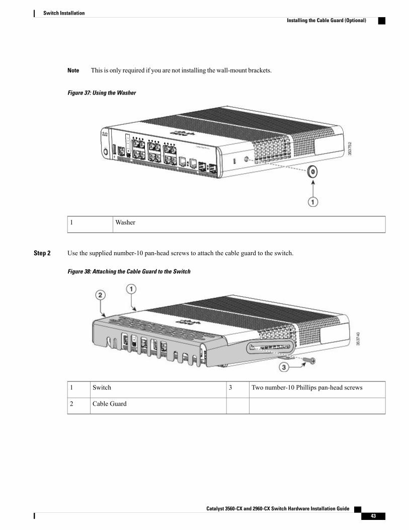
This is only required if you are not installing the wall-mount brackets.Note
Figure 37: Using the Washer
Washer1
Step 2 Use the supplied number-10 pan-head screws to attach the cable guard to the switch.
Figure 38: Attaching the Cable Guard to the Switch
Two number-10 Phillips pan-head screws3Switch1
Cable Guard2
Catalyst 3560-CX and 2960-CX Switch Hardware Installation Guide 43
Switch InstallationInstalling the Cable Guard (Optional)
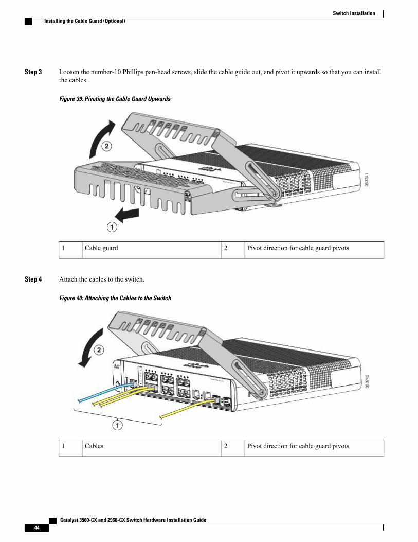
Step 3 Loosen the number-10 Phillips pan-head screws, slide the cable guide out, and pivot it upwards so that you can installthe cables.
Figure 39: Pivoting the Cable Guard Upwards
Pivot direction for cable guard pivots2Cable guard1
Step 4 Attach the cables to the switch.
Figure 40: Attaching the Cables to the Switch
Pivot direction for cable guard pivots2Cables1
Catalyst 3560-CX and 2960-CX Switch Hardware Installation Guide44
Switch InstallationInstalling the Cable Guard (Optional)
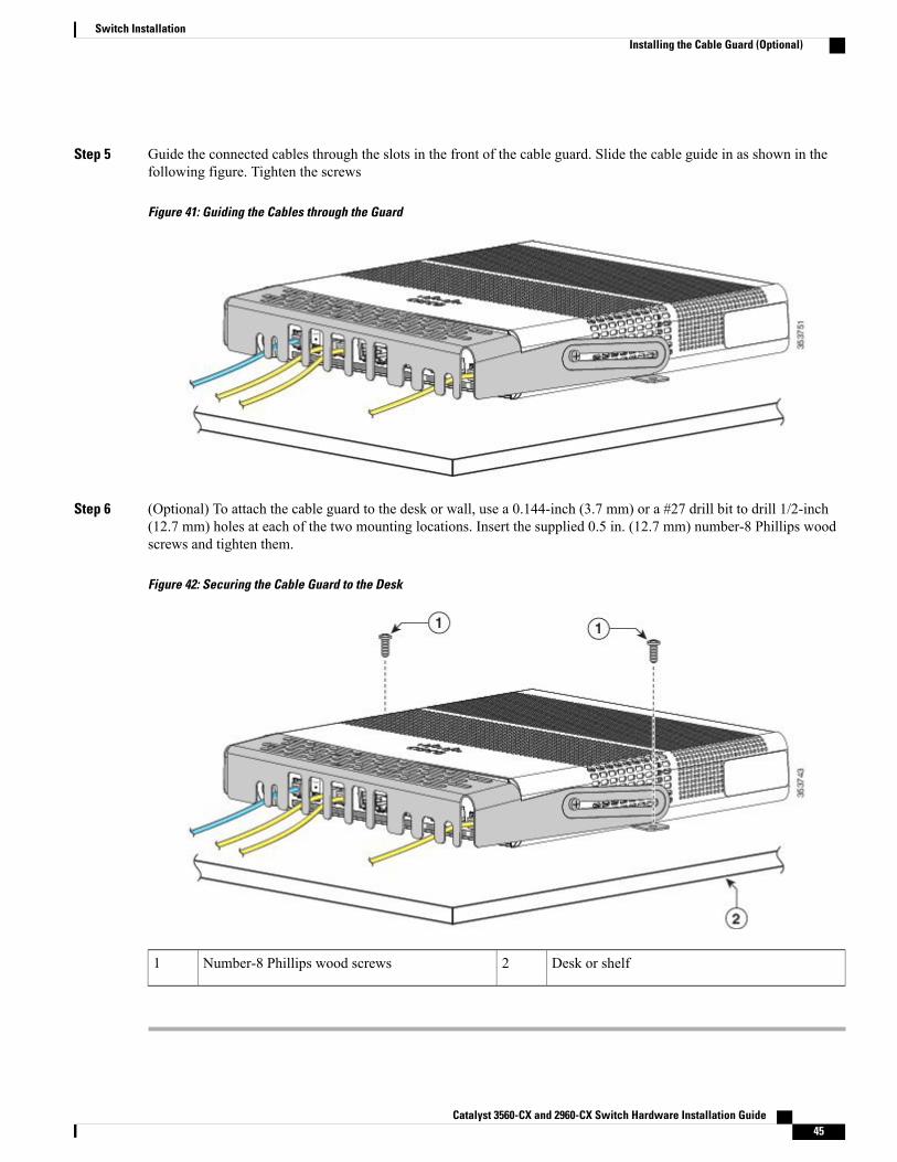
Step 5 Guide the connected cables through the slots in the front of the cable guard. Slide the cable guide in as shown in thefollowing figure. Tighten the screws
Figure 41: Guiding the Cables through the Guard
Step 6 (Optional) To attach the cable guard to the desk or wall, use a 0.144-inch (3.7 mm) or a #27 drill bit to drill 1/2-inch(12.7 mm) holes at each of the two mounting locations. Insert the supplied 0.5 in. (12.7 mm) number-8 Phillips woodscrews and tighten them.
Figure 42: Securing the Cable Guard to the Desk
Desk or shelf2Number-8 Phillips wood screws1
Catalyst 3560-CX and 2960-CX Switch Hardware Installation Guide 45
Switch InstallationInstalling the Cable Guard (Optional)
Installing SFP and SFP+ModulesSome switch models support SFP modules, SFP+ modules, or both. The SFP slots support only the SFPmodules. The SFP+ slots support both SFP and SFP+ modules.
See the switch release notes on Cisco.com for the list of supported SFPmodules. Use only Cisco SFPmoduleson the switch. Each Cisco module has an internal serial EEPROM that is encoded with security information.This encoding provides a way for Cisco to identify and validate that the module meets the requirements forthe switch.
For information about installing, removing, cabling, and troubleshooting SFP modules, see the moduledocumentation that shipped with your device.
Installing an SFP or SFP+Module
Before You Begin
When installing SFP or SFP+ modules, observe these guidelines:
• Do not remove the dust plugs from the modules or the rubber caps from the fiber-optic cable until youare ready to connect the cable. The plugs and caps protect the module ports and cables from contaminationand ambient light.
• To prevent ESD damage, follow your normal board and component handling procedures when connectingcables to the switch and other devices.
Removing and installing an SFP or SFP+ module can shorten its useful life. Do notremove and insert any module more often than is absolutely necessary.
Caution
Class 1 laser product. Statement 1008Warning
Step 1 Attach an ESD-preventive wrist strap to your wrist and to a bare metal surface.Step 2 Find the send (TX) and receive (RX) markings on the module top.
On some SFP or SFP+ modules, the send and receive (TX and RX) markings might be replaced by arrows that show thedirection of the connection.
Catalyst 3560-CX and 2960-CX Switch Hardware Installation Guide46
Switch InstallationInstalling SFP and SFP+Modules
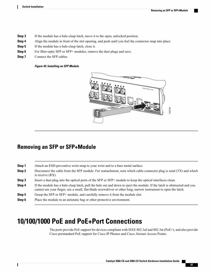
Step 3 If the module has a bale-clasp latch, move it to the open, unlocked position.Step 4 Align the module in front of the slot opening, and push until you feel the connector snap into place.Step 5 If the module has a bale-clasp latch, close it.Step 6 For fiber-optic SFP or SFP+ modules, remove the dust plugs and save.Step 7 Connect the SFP cables.
Figure 43: Installing an SFP Module
Removing an SFP or SFP+Module
Step 1 Attach an ESD-preventive wrist strap to your wrist and to a bare metal surface.Step 2 Disconnect the cable from the SFP module. For reattachment, note which cable connector plug is send (TX) and which
is receive (RX).Step 3 Insert a dust plug into the optical ports of the SFP or SFP+ module to keep the optical interfaces clean.Step 4 If the module has a bale-clasp latch, pull the bale out and down to eject the module. If the latch is obstructed and you
cannot use your finger, use a small, flat-blade screwdriver or other long, narrow instrument to open the latch.Step 5 Grasp the SFP or SFP+ module, and carefully remove it from the module slot.Step 6 Place the module in an antistatic bag or other protective environment.
10/100/1000 PoE and PoE+Port ConnectionsThe ports provide PoE support for devices compliant with IEEE 802.3af and 802.3at (PoE+), and also provideCisco prestandard PoE support for Cisco IP Phones and Cisco Aironet Access Points.
Catalyst 3560-CX and 2960-CX Switch Hardware Installation Guide 47
Switch InstallationRemoving an SFP or SFP+Module
On a per-port basis, you can control whether or not a port automatically provides power when an IP phoneor an access point is connected.
To access an advanced PoE planning tool, use the Cisco Power Calculator available on Cisco.com at thisURL: http://tools.cisco.com/cpc/launch.jsp
You can use this application to calculate the power supply requirements for a specific PoE configuration. Theresults show output current, output power, and system heat dissipation.
Voltages that present a shock hazard may exist on Power over Ethernet (PoE) circuits if interconnectionsare made using uninsulated exposed metal contacts, conductors, or terminals. Avoid using suchinterconnection methods, unless the exposed metal parts are located within a restricted access locationand users and service people who are authorized within the restricted access location are made aware ofthe hazard. A restricted access area can be accessed only through the use of a special tool, lock and keyor other means of security. Statement 1072
Warning
Category 5e and Category 6 cables can store high levels of static electricity. Always ground the cables toa suitable and safe earth ground before connecting them to the switch or other devices.
Caution
Noncompliant cabling or powered devices can cause a PoE port fault. Use only standard-compliant cablingto connect Cisco prestandard IP Phones and wireless access points, IEEE 802.3af, or 802.3at(PoE+)-compliant devices. You must remove any cable or device that causes a PoE fault.
Caution
SUMMARY STEPS
1. Connect one end of the cable to the switch PoE port.2. Connect the other end of the cable to an RJ-45 connector on the other device. The port LED turns on when
both devices have established link.3. Reconfigure and reboot the connected device if needed.4. Repeat Steps 1 through 3 to connect each device.
DETAILED STEPS
Step 1 Connect one end of the cable to the switch PoE port.Step 2 Connect the other end of the cable to an RJ-45 connector on the other device. The port LED turns on when both devices
have established link.The port LED is amber while STP discovers the topology and searches for loops. This process takes about 30 seconds,and then the port LED turns green. If the LED is off, the other device might not be turned on, there might be a cableproblem, or there might be a problem with the adapter in the other device.
Step 3 Reconfigure and reboot the connected device if needed.Step 4 Repeat Steps 1 through 3 to connect each device.
Many legacy powered devices, including older Cisco IP phones and access points that do not fully support IEEE802.3af, might not support PoE when connected to the switches by a crossover cable.
Note
Catalyst 3560-CX and 2960-CX Switch Hardware Installation Guide48
Switch Installation10/100/1000 PoE and PoE+Port Connections
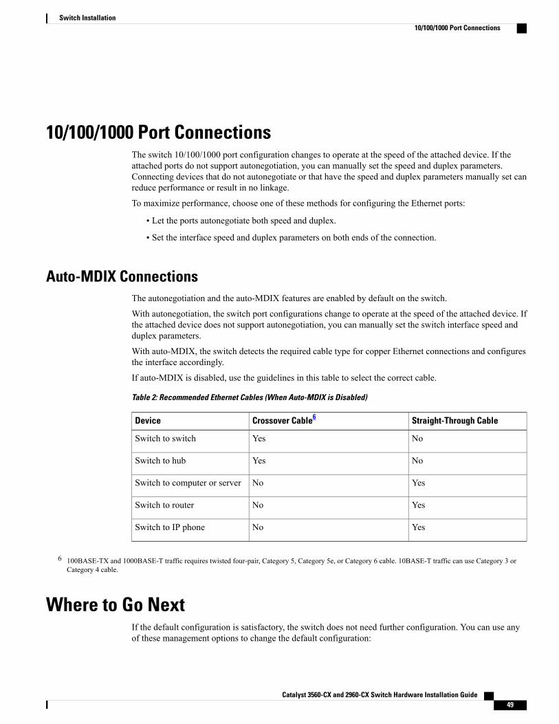
10/100/1000 Port ConnectionsThe switch 10/100/1000 port configuration changes to operate at the speed of the attached device. If theattached ports do not support autonegotiation, you can manually set the speed and duplex parameters.Connecting devices that do not autonegotiate or that have the speed and duplex parameters manually set canreduce performance or result in no linkage.
To maximize performance, choose one of these methods for configuring the Ethernet ports:
• Let the ports autonegotiate both speed and duplex.
• Set the interface speed and duplex parameters on both ends of the connection.
Auto-MDIX ConnectionsThe autonegotiation and the auto-MDIX features are enabled by default on the switch.
With autonegotiation, the switch port configurations change to operate at the speed of the attached device. Ifthe attached device does not support autonegotiation, you can manually set the switch interface speed andduplex parameters.
With auto-MDIX, the switch detects the required cable type for copper Ethernet connections and configuresthe interface accordingly.
If auto-MDIX is disabled, use the guidelines in this table to select the correct cable.
Table 2: Recommended Ethernet Cables (When Auto-MDIX is Disabled)
Straight-Through CableCrossover Cable6Device
NoYesSwitch to switch
NoYesSwitch to hub
YesNoSwitch to computer or server
YesNoSwitch to router
YesNoSwitch to IP phone
6 100BASE-TX and 1000BASE-T traffic requires twisted four-pair, Category 5, Category 5e, or Category 6 cable. 10BASE-T traffic can use Category 3 orCategory 4 cable.
Where to Go NextIf the default configuration is satisfactory, the switch does not need further configuration. You can use anyof these management options to change the default configuration:
Catalyst 3560-CX and 2960-CX Switch Hardware Installation Guide 49
Switch Installation10/100/1000 Port Connections
• Start the Network Assistant application, which is described in the getting started guide. Through thisGUI, you can configure and monitor a switch cluster or an individual switch.
• Use the CLI to configure the switch as a member of a cluster or as an individual switch from the console.
• Use the Cisco Prime Infrastructure application.
Catalyst 3560-CX and 2960-CX Switch Hardware Installation Guide50
Switch InstallationWhere to Go Next
C H A P T E R 3Troubleshooting
This chapter contains these topics:
• Diagnosing Problems, page 51
• Resetting the Switch, page 55
• Finding the Switch Serial Number, page 56
Diagnosing ProblemsThe LEDs on the front panel provide troubleshooting information about the switch. They show POST failures,port-connectivity problems, and overall switch performance. You can also get statistics fromDeviceManager,from the CLI, or from an SNMP workstation.
Switch POST Results
POST failures are usually fatal. Contact your Cisco technical support representative if your switch doesnot pass POST.
Note
Switch LEDsIf you have physical access to the switch, look at the port LEDs for troubleshooting information about theswitch. See the LED section for a description of the LED colors and their meanings.
Catalyst 3560-CX and 2960-CX Switch Hardware Installation Guide 51
Switch Connections
Bad or Damaged CableAlways examine the cable for marginal damage or failure. A cable might be just good enough to connect atthe physical layer, but it could corrupt packets as a result of subtle damage to the wiring or connectors. Youcan identify this situation because the port has many packet errors or the port constantly flaps (loses andregains link).
• Examine or exchange the copper or fiber-optic cable with a known, good cable.
• Look for broken or missing pins on cable connectors.
• Rule out any bad patch panel connections or media convertors between the source and the destination.If possible, bypass the patch panel, or eliminate faulty media convertors (fiber-optic-to-copper).
• Try the cable in another port or interface, if possible, to see if the problem follows the cable.
Ethernet and Fiber-Optic CablesMake sure that you have the correct cable for the connection.
• For Ethernet, use Category 3 copper cable for 10Mb/s UTP connections. Use either Category 5, Category5e, or Category 6 UTP for 10/100/1000 Mb/s connections.
• For fiber-optic cables, verify that you have the correct cable for the distance and port type. Make surethat the connected device ports both match and use the same type encoding, optical frequency, and fibertype.
• For copper connections, determine if a crossover cable was used when a straight-through was requiredor the reverse. Enable auto-MDIX on the switch, or replace the cable.
Link StatusVerify that both sides have link. A single broken wire or a shutdown port can cause one side to show linkeven though the other side does not have link.
A port LED that is on does not guarantee that the cable is fully functional. The cable might have encounteredphysical stress that causes it to function at a marginal level. If the port LED does not turn on:
• Connect the cable from the switch to a known good device.
• Make sure that both ends of the cable are connected to the correct ports.
• Verify that both devices have power.
• Verify that you are using the correct cable type.
• Look for loose connections. Sometimes a cable appears to be seated, but is not. Disconnect the cableand then reconnect it.
Catalyst 3560-CX and 2960-CX Switch Hardware Installation Guide52
TroubleshootingSwitch Connections
10/100/1000 Port ConnectionsA port appears to malfunction:
• Use the Mode button to show the status for all ports.
• Use the show interfaces privileged EXEC command to see if the port is error-disabled, disabled, orshutdown. Reenable the port if necessary.
10/100/1000 PoE+ Port ConnectionsA powered device connected to a PoE port does not receive power:
• Use the Mode button to show the PoE status for all ports.
• Use the show interfaces privileged EXEC command to see if the port is in error-disabled, disabled, orshutdown. Reenable the port if necessary.
• Verify that the power supply installed in the switch meets the power requirements of your connecteddevices.
• Verify that there is sufficient PoE power budget to provide power to the attached device. Use the showpower inline global configuration command to check on the available PoE power budget.
• Verify the cable type. Many legacy powered devices, including older Cisco IP phones and access pointsthat do not fully support IEEE 802.3af, might not support PoE when connected to the switch by acrossover cable. Replace the crossover cable with a straight-through cable.
Noncompliant cabling or powered devices can cause a PoE port fault. Use onlystandard-compliant cabling to connect Cisco prestandard IP Phones and wireless accesspoints or IEEE 802.3af-compliant devices. You must remove any cable or device thatcauses a PoE fault.
Caution
SFP and SFP+ ModuleUse only Cisco SFP or SFP+ modules in the switch. Each Cisco module has an internal serial EEPROM thatis encoded with security information. This encoding provides a way for Cisco to identify and validate that themodule meets the requirements for the switch.
• Inspect the SFP module. Exchange the suspect module with a known good module. Verify that themodule is supported on this platform. (The switch release notes on Cisco.com list the SFP modules thatthe switch supports.)
• Use the show interfaces privileged EXEC command to see if the port or module is error-disabled,disabled, or shutdown. Reenable the port if needed.
• Make sure that all fiber-optic connections are properly cleaned and securely connected.
Catalyst 3560-CX and 2960-CX Switch Hardware Installation Guide 53
TroubleshootingSwitch Connections
Interface SettingsVerify that the interface is not disabled or powered off. If an interface is manually shut down on either sideof the link, it does not come up until you reenable the interface. Use the show interfaces privileged EXECcommand to see if the interface is error-disabled, disabled, or shutdown on either side of the connection. Ifneeded, reenable the interface.
Ping End DevicePing from the directly connected switch first, and then work your way back port by port, interface by interface,trunk by trunk, until you find the source of the connectivity issue. Make sure that each switch can identifythe end device MAC address in its Content-Addressable Memory (CAM) table.
Spanning Tree LoopsSTP loops can cause serious performance issues that look like port or interface problems.
A unidirectional link can cause loops. It occurs when the traffic sent by the switch is received by its neighbor,but the traffic from the neighbor is not received by the switch. A broken fiber-optic cable, other cablingproblems, or a port issue could cause this one-way communication.
You can enable UniDirectional Link Detection (UDLD) on the switch to help identify unidirectional linkproblems.
Switch Performance
Speed, Duplex, and AutonegotiationIf the port statistics show a large amount of alignment errors, frame check sequence (FCS), or late-collisionserrors, this might mean a speed or duplex mismatch.
A common issue with speed and duplex occurs when duplex and speed settings are mismatched between twoswitches, between a switch and a router, or between the switch and a workstation or server. Mismatches canhappen when manually setting the speed and duplex or from autonegotiation issues between the two devices.
To maximize switch performance and to ensure a link, follow one of these guidelines when changing theduplex or the speed settings.
• Let both ports autonegotiate both speed and duplex.
• Manually set the speed and duplex parameters for the interfaces on both ends of the connection.
• If a remote device does not autonegotiate, use the same duplex settings on the two ports. The speedparameter adjusts itself even if the connected port does not autonegotiate.
Autonegotiation and Network Interface CardsProblems sometimes occur between the switch and third-party network interface cards (NICs). By default,the switch ports and interfaces autonegotiate. Laptops or other devices are commonly set to autonegotiate,yet sometimes autonegotiation issues occur.
Catalyst 3560-CX and 2960-CX Switch Hardware Installation Guide54
TroubleshootingSwitch Performance
To troubleshoot autonegotiation problems, try manually setting both sides of the connection. If this does notsolve the problem, there could be a problem with the firmware or software on your NIC. You can resolve thisby upgrading the NIC driver to the latest version.
Cabling DistanceIf the port statistics show excessive FCS, late-collision, or alignment errors, verify that the cable distancefrom the switch to the connected device meets the recommended guidelines.
Resetting the Switch
Resetting the switch reboots the switch.Note
To reset the switch:
Step 1 At the switch prompt, enter enable, and press Return or Enter.
Step 2 At the Privileged EXEC prompt, switch#, enter setup and press Return or Enter.The switch displays the prompt to run the initial configuration dialog.
Catalyst 3560-CX and 2960-CX Switch Hardware Installation Guide 55
TroubleshootingResetting the Switch
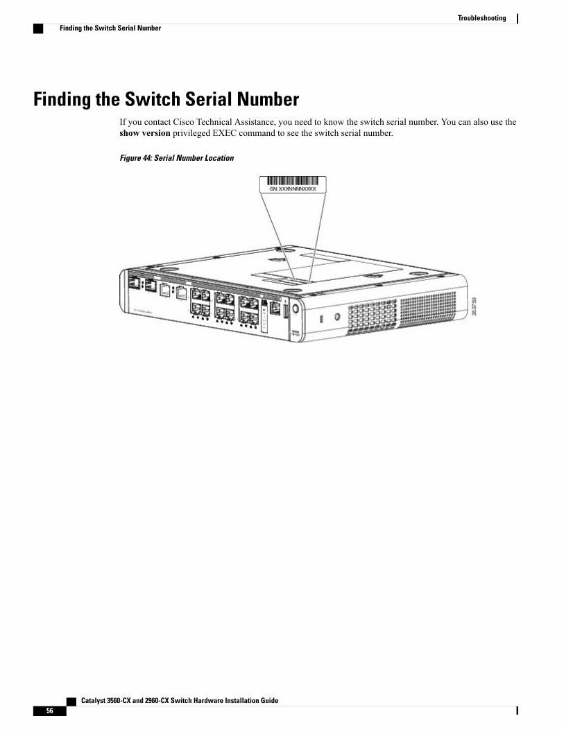
Finding the Switch Serial NumberIf you contact Cisco Technical Assistance, you need to know the switch serial number. You can also use theshow version privileged EXEC command to see the switch serial number.
Figure 44: Serial Number Location
Catalyst 3560-CX and 2960-CX Switch Hardware Installation Guide56
TroubleshootingFinding the Switch Serial Number

A P P E N D I X ATechnical Specifications
This appendix contains these topics:
• Environmental Specifications, page 58
• Physical Specifications, page 59
• Power Requirements, page 60
• PoE Power Consumption, page 61
Catalyst 3560-CX and 2960-CX Switch Hardware Installation Guide 57
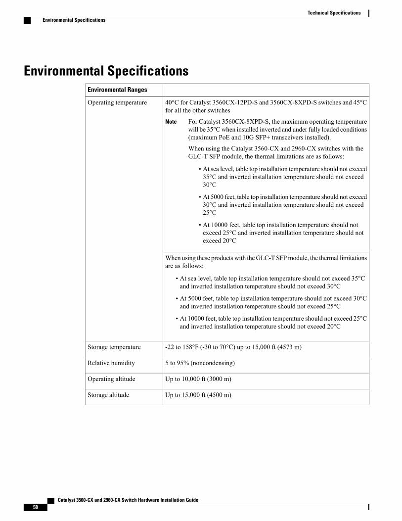
Environmental SpecificationsEnvironmental Ranges
40°C for Catalyst 3560CX-12PD-S and 3560CX-8XPD-S switches and 45°Cfor all the other switches
For Catalyst 3560CX-8XPD-S, the maximum operating temperaturewill be 35°Cwhen installed inverted and under fully loaded conditions(maximum PoE and 10G SFP+ transceivers installed).
When using the Catalyst 3560-CX and 2960-CX switches with theGLC-T SFP module, the thermal limitations are as follows:
Note
• At sea level, table top installation temperature should not exceed35°C and inverted installation temperature should not exceed30°C
• At 5000 feet, table top installation temperature should not exceed30°C and inverted installation temperature should not exceed25°C
• At 10000 feet, table top installation temperature should notexceed 25°C and inverted installation temperature should notexceed 20°C
Operating temperature
When using these products with theGLC-T SFPmodule, the thermal limitationsare as follows:
• At sea level, table top installation temperature should not exceed 35°Cand inverted installation temperature should not exceed 30°C
• At 5000 feet, table top installation temperature should not exceed 30°Cand inverted installation temperature should not exceed 25°C
• At 10000 feet, table top installation temperature should not exceed 25°Cand inverted installation temperature should not exceed 20°C
-22 to 158°F (-30 to 70°C) up to 15,000 ft (4573 m)Storage temperature
5 to 95% (noncondensing)Relative humidity
Up to 10,000 ft (3000 m)Operating altitude
Up to 15,000 ft (4500 m)Storage altitude
Catalyst 3560-CX and 2960-CX Switch Hardware Installation Guide58
Technical SpecificationsEnvironmental Specifications
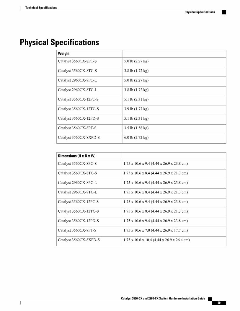
Physical SpecificationsWeight
5.0 lb (2.27 kg)Catalyst 3560CX-8PC-S
3.8 lb (1.72 kg)Catalyst 3560CX-8TC-S
5.0 lb (2.27 kg)Catalyst 2960CX-8PC-L
3.8 lb (1.72 kg)Catalyst 2960CX-8TC-L
5.1 lb (2.31 kg)Catalyst 3560CX-12PC-S
3.9 lb (1.77 kg)Catalyst 3560CX-12TC-S
5.1 lb (2.31 kg)Catalyst 3560CX-12PD-S
3.5 lb (1.58 kg)Catalyst 3560CX-8PT-S
6.0 lb (2.72 kg)Catalyst 3560CX-8XPD-S
Dimensions (H x D x W)
1.75 x 10.6 x 9.4 (4.44 x 26.9 x 23.8 cm)Catalyst 3560CX-8PC-S
1.75 x 10.6 x 8.4 (4.44 x 26.9 x 21.3 cm)Catalyst 3560CX-8TC-S
1.75 x 10.6 x 9.4 (4.44 x 26.9 x 23.8 cm)Catalyst 2960CX-8PC-L
1.75 x 10.6 x 8.4 (4.44 x 26.9 x 21.3 cm)Catalyst 2960CX-8TC-L
1.75 x 10.6 x 9.4 (4.44 x 26.9 x 23.8 cm)Catalyst 3560CX-12PC-S
1.75 x 10.6 x 8.4 (4.44 x 26.9 x 21.3 cm)Catalyst 3560CX-12TC-S
1.75 x 10.6 x 9.4 (4.44 x 26.9 x 23.8 cm)Catalyst 3560CX-12PD-S
1.75 x 10.6 x 7.0 (4.44 x 26.9 x 17.7 cm)Catalyst 3560CX-8PT-S
1.75 x 10.6 x 10.4 (4.44 x 26.9 x 26.4 cm)Catalyst 3560CX-8XPD-S
Catalyst 3560-CX and 2960-CX Switch Hardware Installation Guide 59
Technical SpecificationsPhysical Specifications
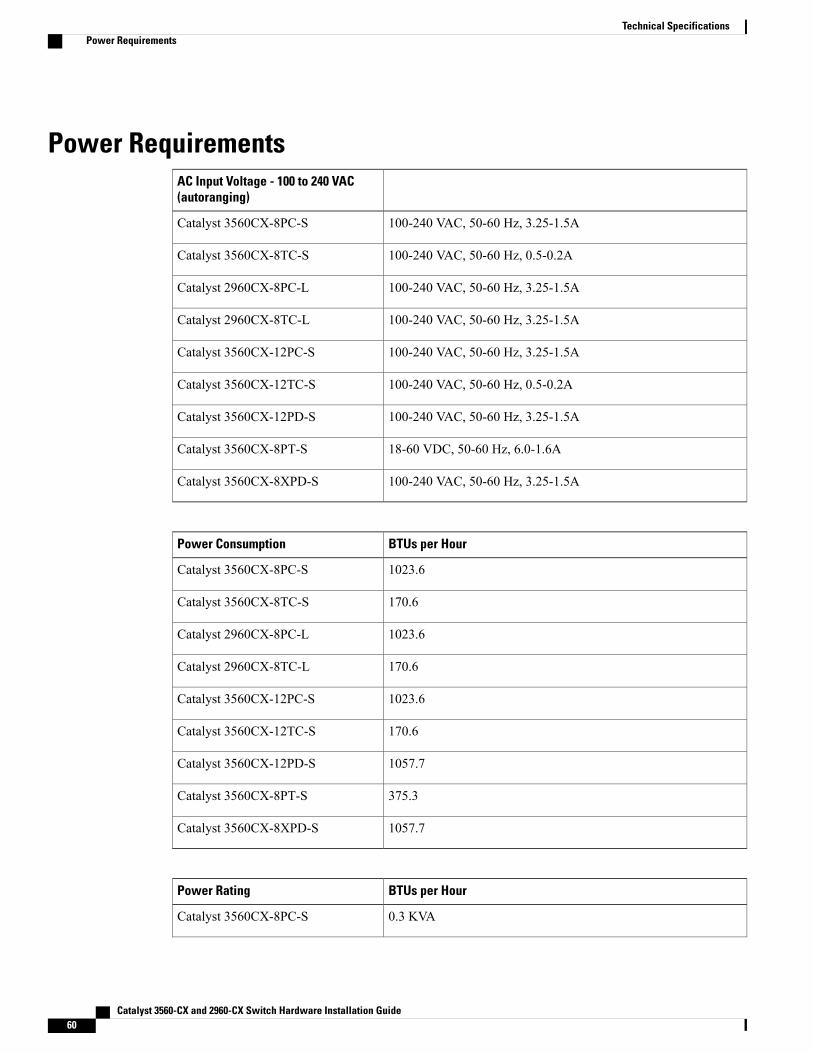
Power RequirementsAC Input Voltage - 100 to 240 VAC(autoranging)
100-240 VAC, 50-60 Hz, 3.25-1.5ACatalyst 3560CX-8PC-S
100-240 VAC, 50-60 Hz, 0.5-0.2ACatalyst 3560CX-8TC-S
100-240 VAC, 50-60 Hz, 3.25-1.5ACatalyst 2960CX-8PC-L
100-240 VAC, 50-60 Hz, 3.25-1.5ACatalyst 2960CX-8TC-L
100-240 VAC, 50-60 Hz, 3.25-1.5ACatalyst 3560CX-12PC-S
100-240 VAC, 50-60 Hz, 0.5-0.2ACatalyst 3560CX-12TC-S
100-240 VAC, 50-60 Hz, 3.25-1.5ACatalyst 3560CX-12PD-S
18-60 VDC, 50-60 Hz, 6.0-1.6ACatalyst 3560CX-8PT-S
100-240 VAC, 50-60 Hz, 3.25-1.5ACatalyst 3560CX-8XPD-S
BTUs per HourPower Consumption
1023.6Catalyst 3560CX-8PC-S
170.6Catalyst 3560CX-8TC-S
1023.6Catalyst 2960CX-8PC-L
170.6Catalyst 2960CX-8TC-L
1023.6Catalyst 3560CX-12PC-S
170.6Catalyst 3560CX-12TC-S
1057.7Catalyst 3560CX-12PD-S
375.3Catalyst 3560CX-8PT-S
1057.7Catalyst 3560CX-8XPD-S
BTUs per HourPower Rating
0.3 KVACatalyst 3560CX-8PC-S
Catalyst 3560-CX and 2960-CX Switch Hardware Installation Guide60
Technical SpecificationsPower Requirements
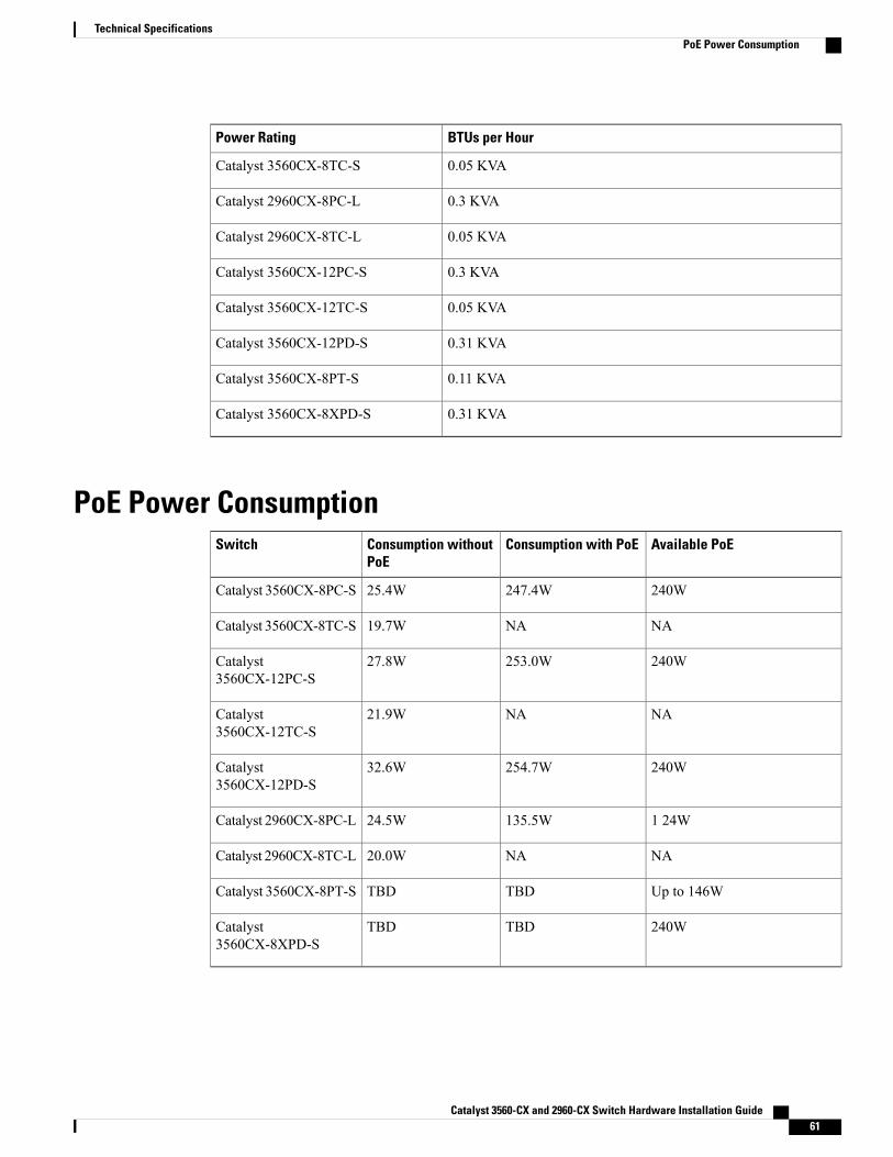
BTUs per HourPower Rating
0.05 KVACatalyst 3560CX-8TC-S
0.3 KVACatalyst 2960CX-8PC-L
0.05 KVACatalyst 2960CX-8TC-L
0.3 KVACatalyst 3560CX-12PC-S
0.05 KVACatalyst 3560CX-12TC-S
0.31 KVACatalyst 3560CX-12PD-S
0.11 KVACatalyst 3560CX-8PT-S
0.31 KVACatalyst 3560CX-8XPD-S
PoE Power ConsumptionAvailable PoEConsumption with PoEConsumption without
PoESwitch
240W247.4W25.4WCatalyst 3560CX-8PC-S
NANA19.7WCatalyst 3560CX-8TC-S
240W253.0W27.8WCatalyst3560CX-12PC-S
NANA21.9WCatalyst3560CX-12TC-S
240W254.7W32.6WCatalyst3560CX-12PD-S
1 24W135.5W24.5WCatalyst 2960CX-8PC-L
NANA20.0WCatalyst 2960CX-8TC-L
Up to 146WTBDTBDCatalyst 3560CX-8PT-S
240WTBDTBDCatalyst3560CX-8XPD-S
Catalyst 3560-CX and 2960-CX Switch Hardware Installation Guide 61
Technical SpecificationsPoE Power Consumption

Catalyst 3560-CX and 2960-CX Switch Hardware Installation Guide62
Technical SpecificationsPoE Power Consumption
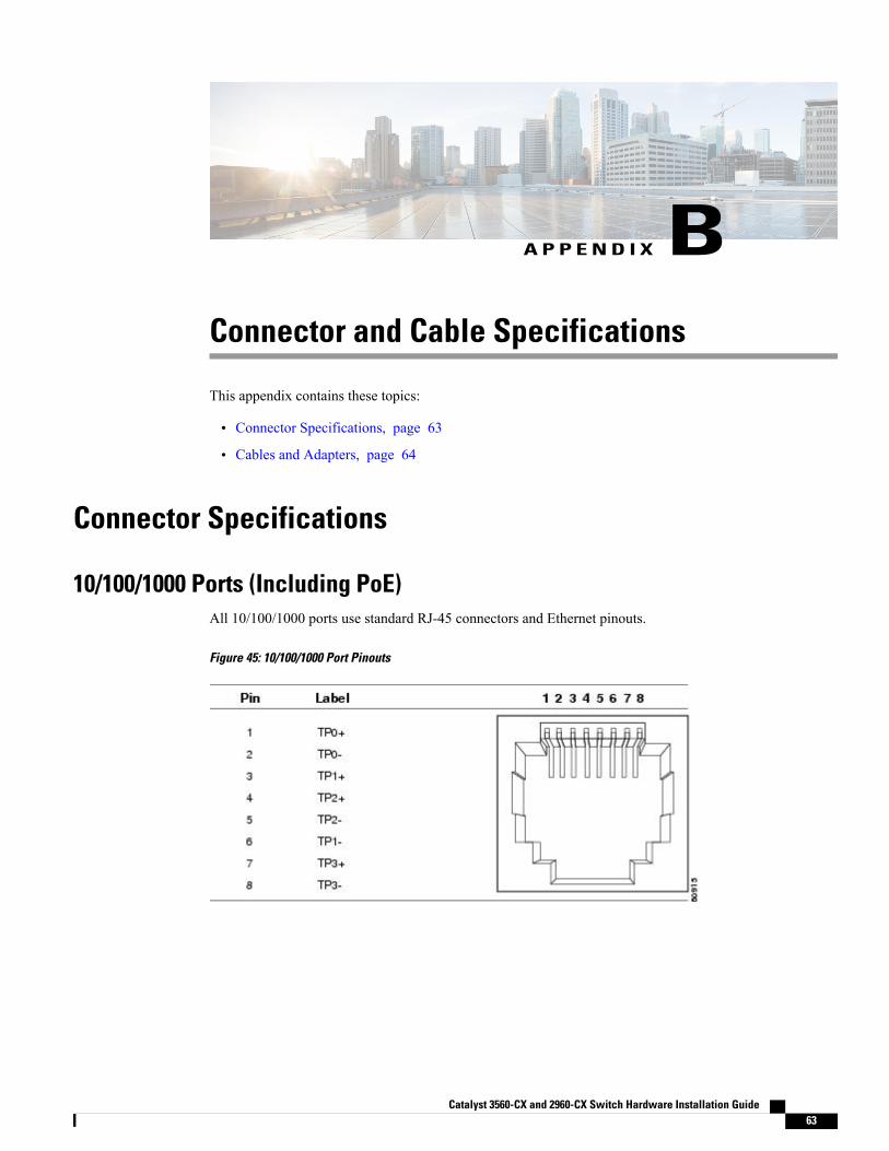
A P P E N D I X BConnector and Cable Specifications
This appendix contains these topics:
• Connector Specifications, page 63
• Cables and Adapters, page 64
Connector Specifications
10/100/1000 Ports (Including PoE)All 10/100/1000 ports use standard RJ-45 connectors and Ethernet pinouts.
Figure 45: 10/100/1000 Port Pinouts
Catalyst 3560-CX and 2960-CX Switch Hardware Installation Guide 63
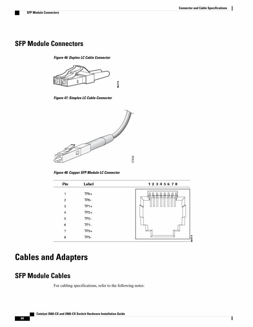
SFP Module Connectors
Figure 46: Duplex LC Cable Connector
Figure 47: Simplex LC Cable Connector
Figure 48: Copper SFP Module LC Connector
Cables and Adapters
SFP Module CablesFor cabling specifications, refer to the following notes:
Catalyst 3560-CX and 2960-CX Switch Hardware Installation Guide64
Connector and Cable SpecificationsSFP Module Connectors

• Cisco SFP and SFP+ Transceiver Module Installation Notes
• Cisco 40-Gigabit QSFP+ Transceiver Modules Installation Note
Each port must match the wave-length specifications on the other end of the cable, and the cable must notexceed the stipulated cable length. Copper 1000BASE-T SFPmodule transceivers use standard four twisted-pair,Category 5 cable at lengths up to 328 feet (100 meters).
Catalyst 3560-CX and 2960-CX Switch Hardware Installation Guide 65
Connector and Cable SpecificationsSFP Module Cables
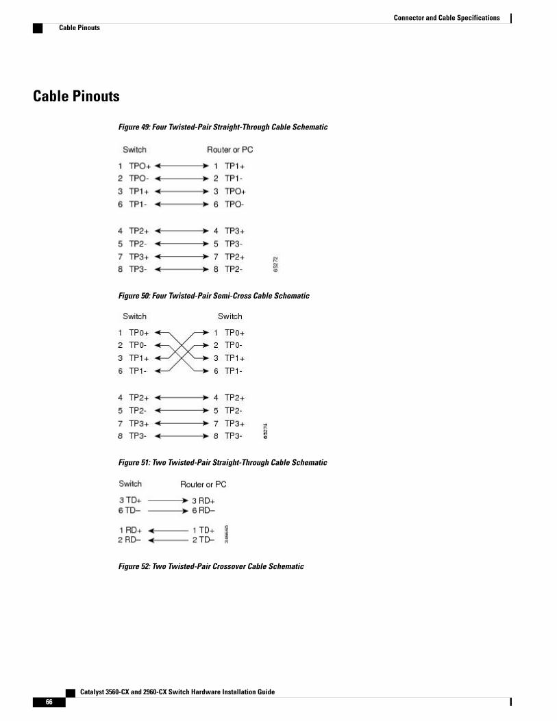
Cable Pinouts
Figure 49: Four Twisted-Pair Straight-Through Cable Schematic
Figure 50: Four Twisted-Pair Semi-Cross Cable Schematic
Figure 51: Two Twisted-Pair Straight-Through Cable Schematic
Figure 52: Two Twisted-Pair Crossover Cable Schematic
Catalyst 3560-CX and 2960-CX Switch Hardware Installation Guide66
Connector and Cable SpecificationsCable Pinouts
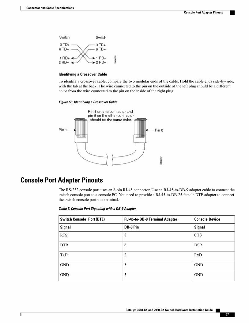
Identifying a Crossover Cable
To identify a crossover cable, compare the two modular ends of the cable. Hold the cable ends side-by-side,with the tab at the back. The wire connected to the pin on the outside of the left plug should be a differentcolor from the wire connected to the pin on the inside of the right plug.
Figure 53: Identifying a Crossover Cable
Console Port Adapter PinoutsThe RS-232 console port uses an 8-pin RJ-45 connector. Use an RJ-45-to-DB-9 adapter cable to connect theswitch console port to a console PC. You need to provide a RJ-45-to-DB-25 female DTE adapter to connectthe switch console port to a terminal.
Table 3: Console Port Signaling with a DB-9 Adapter
Console DeviceRJ-45-to-DB-9 Terminal AdapterSwitch Console Port (DTE)
SignalDB-9 PinSignal
CTS8RTS
DSR6DTR
RxD2TxD
GND5GND
GND5GND
Catalyst 3560-CX and 2960-CX Switch Hardware Installation Guide 67
Connector and Cable SpecificationsConsole Port Adapter Pinouts
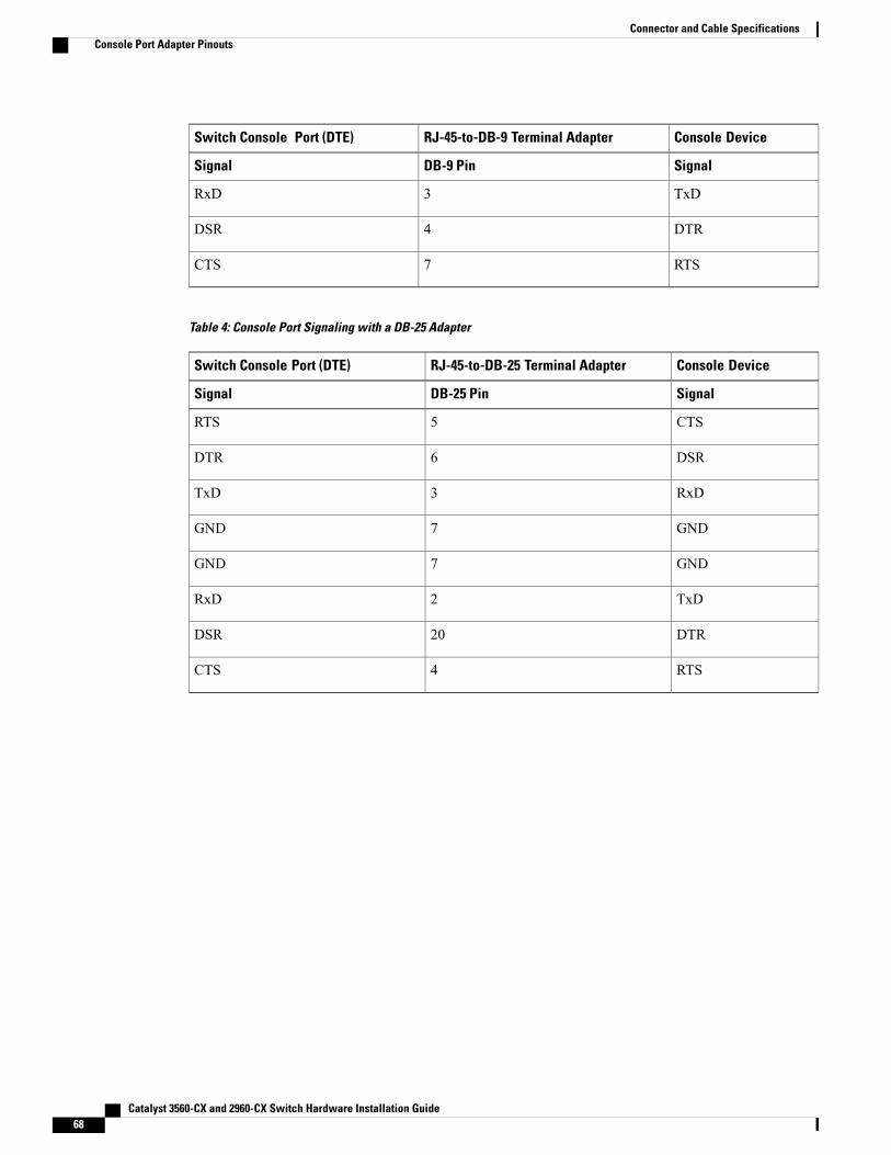
Console DeviceRJ-45-to-DB-9 Terminal AdapterSwitch Console Port (DTE)
SignalDB-9 PinSignal
TxD3RxD
DTR4DSR
RTS7CTS
Table 4: Console Port Signaling with a DB-25 Adapter
Console DeviceRJ-45-to-DB-25 Terminal AdapterSwitch Console Port (DTE)
SignalDB-25 PinSignal
CTS5RTS
DSR6DTR
RxD3TxD
GND7GND
GND7GND
TxD2RxD
DTR20DSR
RTS4CTS
Catalyst 3560-CX and 2960-CX Switch Hardware Installation Guide68
Connector and Cable SpecificationsConsole Port Adapter Pinouts
A P P E N D I X CConfiguring the Switch with the CLI-Based SetupProgram
This appendix contains these topics:
• Accessing the CLI Through Express Setup, page 69
• Accessing the CLI Through the Console Port, page 69
• Entering the Initial Configuration Information, page 77
Accessing the CLI Through Express SetupYou can access the CLI on an unconfigured switch. Set the switch in Express Setup mode and connect aswitch Ethernet port to an Ethernet port on your PC or workstation. Follow the steps described in the gettingstarted guide for turning on the switch and using Express Setup.
When the switch is in Express Setup mode, open a Telnet session to the switch by entering the IP address10.0.0.1. Enter the setup user EXEC command. Enter the information described in IP Settings, on page 77and Completing the Setup Program, on page 78.
After you have entered the configuration information for the switch, save it to flash memory by using thewrite memory privileged EXEC command.
In Express Setup mode, the IP address 10.0.0.1 remains active on the switch until you enter the writememory command. You lose the Telnet connection after entering the write memory command.
Note
Accessing the CLI Through the Console PortYou can access the CLI on a configured or unconfigured switch by connecting the RJ-45 console port or USBconsole port of the switch to your PC or workstation and accessing the switch through a terminal emulationprogram.
Catalyst 3560-CX and 2960-CX Switch Hardware Installation Guide 69
If you have stacked your switches, connect to the console port of one of the switches in the stack. Youcan initially configure the entire stack from any member switch.
Note
Connecting the RJ-45 Console Port
SUMMARY STEPS
1. Connect the RJ-45-to-DB-9 adapter cable to the 9-pin serial port on the PC. Connect the other end of thecable to the switch console port.
2. Start the terminal-emulation program on the PC or the terminal. The program, frequently a PC applicationsuch as HyperTerminal or ProcommPlus, makes communication between the switch and your PC orterminal possible.
3. Configure the baud rate and character format of the PC or terminal to match the console port defaultcharacteristics:
4. Power on the switch as described in the switch getting started guide.5. The PC or terminal displays the bootloader sequence. Press Enter to display the setup prompt. Follow the
steps in Entering the Initial Configuration Information, on page 77.
DETAILED STEPS
Step 1 Connect the RJ-45-to-DB-9 adapter cable to the 9-pin serial port on the PC. Connect the other end of the cable to theswitch console port.
Step 2 Start the terminal-emulation program on the PC or the terminal. The program, frequently a PC application such asHyperTerminal or ProcommPlus, makes communication between the switch and your PC or terminal possible.
Step 3 Configure the baud rate and character format of the PC or terminal to match the console port default characteristics:
• 9600 baud
• 8 data bits
• 1 stop bit
• No parity
• None (flow control)
Step 4 Power on the switch as described in the switch getting started guide.Step 5 The PC or terminal displays the bootloader sequence. Press Enter to display the setup prompt. Follow the steps in
Entering the Initial Configuration Information, on page 77.
Catalyst 3560-CX and 2960-CX Switch Hardware Installation Guide70
Configuring the Switch with the CLI-Based Setup ProgramConnecting the RJ-45 Console Port
Connecting the USB Console Port
SUMMARY STEPS
1. If you are connecting the switch USB console port to a Windows-based PC for the first time, install theUSB driver. See Installing the Cisco Microsoft Windows USB Device Driver, on page 73.
2. Connect a USB cable to the PC USB port. Connect the other end of the cable to the switch mini-B(5-pin-connector) USB console port.
3. Start the terminal-emulation program on the PC or the terminal. The program, frequently a PC applicationsuch as HyperTerminal or ProcommPlus, makes communication between the switch and your PC orterminal possible.
4. Configure the baud rate and character format of the PC or terminal to match the console port defaultcharacteristics:
5. Power on the switch as described in the switch getting started guide.6. The PC or terminal displays the bootloader sequence. Press Enter to display the setup prompt. Follow the
steps in the Setup program.
Catalyst 3560-CX and 2960-CX Switch Hardware Installation Guide 71
Configuring the Switch with the CLI-Based Setup ProgramConnecting the USB Console Port
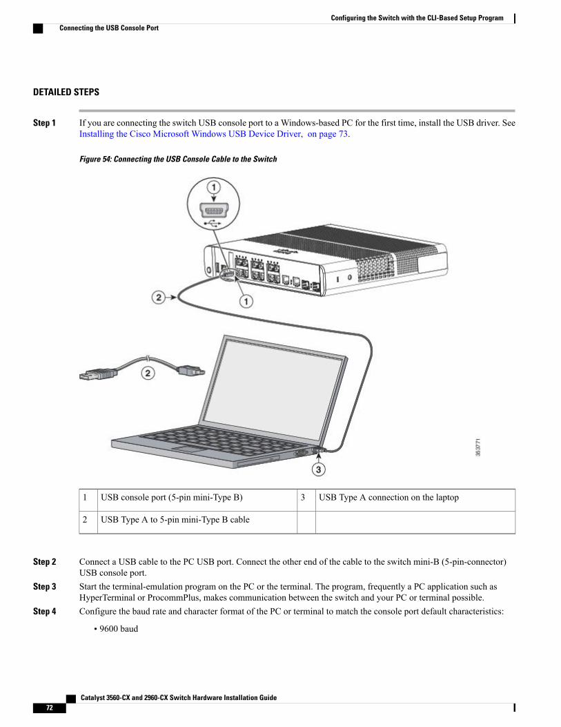
DETAILED STEPS
Step 1 If you are connecting the switch USB console port to a Windows-based PC for the first time, install the USB driver. SeeInstalling the Cisco Microsoft Windows USB Device Driver, on page 73.
Figure 54: Connecting the USB Console Cable to the Switch
USB Type A connection on the laptop3USB console port (5-pin mini-Type B)1
USB Type A to 5-pin mini-Type B cable2
Step 2 Connect a USB cable to the PC USB port. Connect the other end of the cable to the switch mini-B (5-pin-connector)USB console port.
Step 3 Start the terminal-emulation program on the PC or the terminal. The program, frequently a PC application such asHyperTerminal or ProcommPlus, makes communication between the switch and your PC or terminal possible.
Step 4 Configure the baud rate and character format of the PC or terminal to match the console port default characteristics:
• 9600 baud
Catalyst 3560-CX and 2960-CX Switch Hardware Installation Guide72
Configuring the Switch with the CLI-Based Setup ProgramConnecting the USB Console Port
• 8 data bits
• 1 stop bit
• No parity
• None (flow control)
Step 5 Power on the switch as described in the switch getting started guide.Step 6 The PC or terminal displays the bootloader sequence. Press Enter to display the setup prompt. Follow the steps in the
Setup program.
Installing the Cisco Microsoft Windows USB Device DriverA USB device driver must be installed the first time a Microsoft Windows-based PC is connected to the USBconsole port on the switch.
• Installing the Cisco Microsoft Windows XP USB Driver
• Installing the Cisco Microsoft Windows 2000 USB Driver
• Installing the Cisco Microsoft Windows Vista and Windows 7 USB Driver
Installing the Cisco Microsoft Windows XP USB Driver
SUMMARY STEPS
1. Obtain the Cisco USB console driver file from the Cisco.com web site and unzip it.2. If using 32-bit Windows XP, double-click the setup.exe file in the Windows_32 folder. If using 64-bit
Windows XP, double-click the setup(x64).exe file in the Windows_64 folder.3. The Cisco Virtual Com InstallShield Wizard begins.4. The Ready to Install the Program window appears. Click Install.5. The InstallShield Wizard Completed window appears. Click Finish.6. Connect the USB cable to the PC and the switch console port. The USB console port LED turns green,
and the Found New Hardware Wizard appears. Follow the instructions to complete the driver installation.
DETAILED STEPS
Step 1 Obtain the Cisco USB console driver file from the Cisco.com web site and unzip it.
You can download the driver file from the Cisco.com site for downloading the switch software.Note
Catalyst 3560-CX and 2960-CX Switch Hardware Installation Guide 73
Configuring the Switch with the CLI-Based Setup ProgramInstalling the Cisco Microsoft Windows USB Device Driver
Step 2 If using 32-bit Windows XP, double-click the setup.exe file in the Windows_32 folder. If using 64-bit Windows XP,double-click the setup(x64).exe file in the Windows_64 folder.
Step 3 The Cisco Virtual Com InstallShield Wizard begins.Step 4 The Ready to Install the Program window appears. Click Install.Step 5 The InstallShield Wizard Completed window appears. Click Finish.Step 6 Connect the USB cable to the PC and the switch console port. The USB console port LED turns green, and the Found
New Hardware Wizard appears. Follow the instructions to complete the driver installation.
Installing the Cisco Microsoft Windows 2000 USB Driver
SUMMARY STEPS
1. Obtain the Cisco USB console driver file from the Cisco.com web site and unzip it.2. Double-click the setup.exe file.3. The Cisco Virtual Com InstallShield Wizard begins. Click Next.4. The Ready to Install the Program window appears. Click Install.5. The InstallShield Wizard Completed window appears. Click Finish.6. Connect the USB cable to the PC and the switch console port. The USB console port LED turns green,
and the Found New Hardware Wizard appears. Follow the instructions to complete the driver installation.
DETAILED STEPS
Step 1 Obtain the Cisco USB console driver file from the Cisco.com web site and unzip it.
You can download the driver file from the Cisco.com site for downloading the switch software.Note
Step 2 Double-click the setup.exe file.Step 3 The Cisco Virtual Com InstallShield Wizard begins. Click Next.Step 4 The Ready to Install the Program window appears. Click Install.Step 5 The InstallShield Wizard Completed window appears. Click Finish.Step 6 Connect the USB cable to the PC and the switch console port. The USB console port LED turns green, and the Found
New Hardware Wizard appears. Follow the instructions to complete the driver installation.
Catalyst 3560-CX and 2960-CX Switch Hardware Installation Guide74
Configuring the Switch with the CLI-Based Setup ProgramInstalling the Cisco Microsoft Windows USB Device Driver
Installing the Cisco Microsoft Windows Vista and Windows 7 USB Driver
SUMMARY STEPS
1. Obtain the Cisco USB console driver file from the Cisco.com web site and unzip it.2. If using 32-bit Windows Vista or Windows 7, double-click the setup.exe file in the Windows_32 folder.
If using 64-bit Windows Vista or Windows 7, double-click the setup(x64).exe file in the Windows_64folder.
3. The Cisco Virtual Com InstallShield Wizard begins. Click Next.4. The Ready to Install the Program window appears. Click Install.5. The InstallShield Wizard Completed window appears. Click Finish.6. Connect the USB cable to the PC and the switch console port. The USB console port LED turns green,
and the Found New Hardware Wizard appears. Follow the instructions to complete the driver installation.
DETAILED STEPS
Step 1 Obtain the Cisco USB console driver file from the Cisco.com web site and unzip it.
You can download the driver file from the Cisco.com site for downloading the switch software.Note
Step 2 If using 32-bit Windows Vista or Windows 7, double-click the setup.exe file in the Windows_32 folder. If using 64-bitWindows Vista or Windows 7, double-click the setup(x64).exe file in the Windows_64 folder.
Step 3 The Cisco Virtual Com InstallShield Wizard begins. Click Next.Step 4 The Ready to Install the Program window appears. Click Install.
If a User Account Control warning appears, clickAllow - I trust this program to proceed.Note
Step 5 The InstallShield Wizard Completed window appears. Click Finish.Step 6 Connect the USB cable to the PC and the switch console port. The USB console port LED turns green, and the Found
New Hardware Wizard appears. Follow the instructions to complete the driver installation.
Uninstalling the Cisco Microsoft Windows USB Driver
Uninstalling the Cisco Microsoft Windows XP and 2000 USB DriverUse the Windows Add or Remove Programs utility or the setup.exe file.
Using the Setup.exe Program
Before You Begin
Disconnect the switch console terminal before uninstalling the driver.
Catalyst 3560-CX and 2960-CX Switch Hardware Installation Guide 75
Configuring the Switch with the CLI-Based Setup ProgramUninstalling the Cisco Microsoft Windows USB Driver
SUMMARY STEPS
1. Run setup.exe for Windows 32-bit or setup(x64).exe for Windows-64bit. Click Next.2. The InstallShield Wizard for Cisco Virtual Com appears. Click Next.3. When the Program Maintenance window appears, select the Remove radio button. Click Next.4. When the Remove the Program window appears, click Remove.5. When the InstallShield Wizard Completed window appears, click Finish.
DETAILED STEPS
Step 1 Run setup.exe for Windows 32-bit or setup(x64).exe for Windows-64bit. Click Next.Step 2 The InstallShield Wizard for Cisco Virtual Com appears. Click Next.Step 3 When the Program Maintenance window appears, select the Remove radio button. Click Next.Step 4 When the Remove the Program window appears, click Remove.Step 5 When the InstallShield Wizard Completed window appears, click Finish.
Using the Add or Remove Programs Utility
Before You Begin
Disconnect the switch console terminal before uninstalling the driver.
SUMMARY STEPS
1. Click Start > Control Panel > Add or Remove Programs.2. Scroll to Cisco Virtual Com and click Remove.3. When the Program Maintenance window appears, select the Remove radio button. Click Next.
DETAILED STEPS
Step 1 Click Start > Control Panel > Add or Remove Programs.Step 2 Scroll to Cisco Virtual Com and click Remove.Step 3 When the Program Maintenance window appears, select the Remove radio button. Click Next.
Uninstalling the Cisco Microsoft Windows Vista and Windows 7 USB Driver
Before You Begin
Disconnect the switch console terminal before uninstalling the driver.
Catalyst 3560-CX and 2960-CX Switch Hardware Installation Guide76
Configuring the Switch with the CLI-Based Setup ProgramUninstalling the Cisco Microsoft Windows USB Driver
SUMMARY STEPS
1. Run setup.exe for Windows 32-bit or setup(x64).exe for Windows-64bit. Click Next.2. The InstallShield Wizard for Cisco Virtual Com appears. Click Next.3. When the Program Maintenance window appears, select the Remove radio button. Click Next.4. When the Remove the Program window appears, click Remove.5. When the InstallShield Wizard Completed window appears, click Finish.
DETAILED STEPS
Step 1 Run setup.exe for Windows 32-bit or setup(x64).exe for Windows-64bit. Click Next.Step 2 The InstallShield Wizard for Cisco Virtual Com appears. Click Next.Step 3 When the Program Maintenance window appears, select the Remove radio button. Click Next.Step 4 When the Remove the Program window appears, click Remove.
If a User Account Control warning appears, clickAllow - I trust this program to proceed.Note
Step 5 When the InstallShield Wizard Completed window appears, click Finish.
Entering the Initial Configuration InformationTo set up the switch, you need to complete the setup program, which runs automatically after the switch ispowered on. You must assign an IP address and other configuration information necessary for the switch tocommunicate with the local routers and the Internet. This information is also needed to use Device Manageror Cisco Network Assistant to configure and manage the switch.
IP SettingsObtain this information from your network administrator before you start the setup program:
• Switch IP address
• Subnet mask (IP netmask)
• Default gateway (router)
• Enable secret password
• Enable password
• Telnet password
Catalyst 3560-CX and 2960-CX Switch Hardware Installation Guide 77
Configuring the Switch with the CLI-Based Setup ProgramEntering the Initial Configuration Information
Completing the Setup ProgramIf your switches are stacked and there are multiple console connections to individual switches in the stack,the initial setup dialog box appears at the console where you first press Enter.
SUMMARY STEPS
1. Enter Yes at these two prompts:2. Enter a host name for the switch, and press Return.3. Enter an enable secret password, and press Return.4. Enter an enable password, and press Return.5. Enter a virtual terminal (Telnet) password, and press Return.6. To configure the country code, enter yes and press Return.7. Enter the country code, and press Return.8. (Optional) Configure Simple Network Management Protocol (SNMP) by responding to the prompts. You
can also configure SNMP later through the CLI, Device Manager, or the Network Assistant application.To configure SNMP later, enter no.
9. Enter the interface name (physical interface or VLAN name) of the connection to the management network,and press Return. For this release, always use vlan1 as that interface.
10. Configure the interface by entering the switch IP address and subnet mask and pressing Return. The IPaddress and subnet masks shown are examples.
11. EnterY to configure the switch as the cluster command switch. EnterN to configure it as a member switchor as a standalone switch.
12. From these choices that appear, make your selection and press Return.
DETAILED STEPS
Step 1 Enter Yes at these two prompts:
Would you like to enter the initial configuration dialog? [yes/no]: yes
At any point you may enter a question mark '?' for help.Use ctrl-c to abort configuration dialog at any prompt.Default settings are in square brackets '[]'.
Basic management setup configures only enough connectivityfor management of the system, extended setup will ask youto configure each interface on the system.
Would you like to enter basic management setup? [yes/no]: yes
Step 2 Enter a host name for the switch, and press Return.
Catalyst 3560-CX and 2960-CX Switch Hardware Installation Guide78
Configuring the Switch with the CLI-Based Setup ProgramCompleting the Setup Program
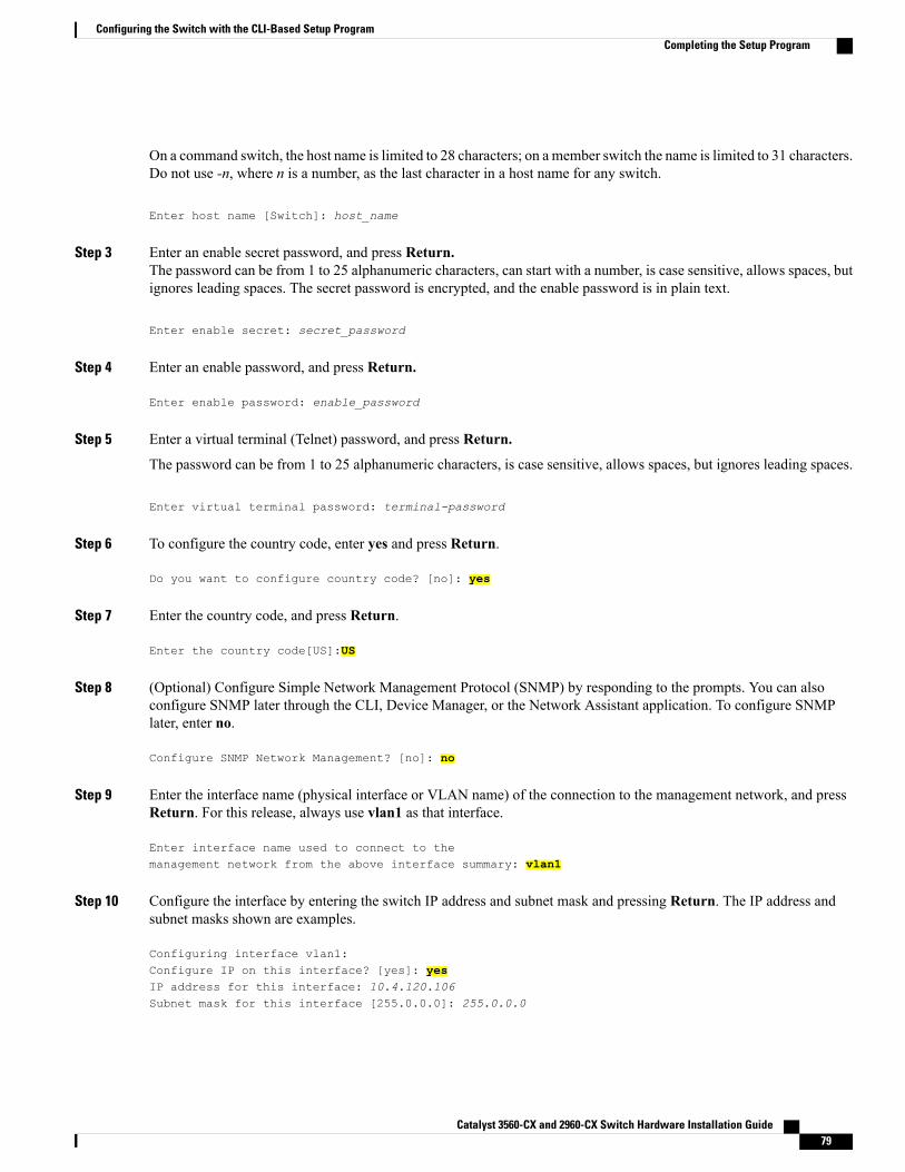
On a command switch, the host name is limited to 28 characters; on a member switch the name is limited to 31 characters.Do not use -n, where n is a number, as the last character in a host name for any switch.
Enter host name [Switch]: host_name
Step 3 Enter an enable secret password, and press Return.The password can be from 1 to 25 alphanumeric characters, can start with a number, is case sensitive, allows spaces, butignores leading spaces. The secret password is encrypted, and the enable password is in plain text.
Enter enable secret: secret_password
Step 4 Enter an enable password, and press Return.
Enter enable password: enable_password
Step 5 Enter a virtual terminal (Telnet) password, and press Return.
The password can be from 1 to 25 alphanumeric characters, is case sensitive, allows spaces, but ignores leading spaces.
Enter virtual terminal password: terminal-password
Step 6 To configure the country code, enter yes and press Return.
Do you want to configure country code? [no]: yes
Step 7 Enter the country code, and press Return.
Enter the country code[US]:US
Step 8 (Optional) Configure Simple Network Management Protocol (SNMP) by responding to the prompts. You can alsoconfigure SNMP later through the CLI, Device Manager, or the Network Assistant application. To configure SNMPlater, enter no.
Configure SNMP Network Management? [no]: no
Step 9 Enter the interface name (physical interface or VLAN name) of the connection to the management network, and pressReturn. For this release, always use vlan1 as that interface.
Enter interface name used to connect to themanagement network from the above interface summary: vlan1
Step 10 Configure the interface by entering the switch IP address and subnet mask and pressing Return. The IP address andsubnet masks shown are examples.
Configuring interface vlan1:Configure IP on this interface? [yes]: yesIP address for this interface: 10.4.120.106Subnet mask for this interface [255.0.0.0]: 255.0.0.0
Catalyst 3560-CX and 2960-CX Switch Hardware Installation Guide 79
Configuring the Switch with the CLI-Based Setup ProgramCompleting the Setup Program
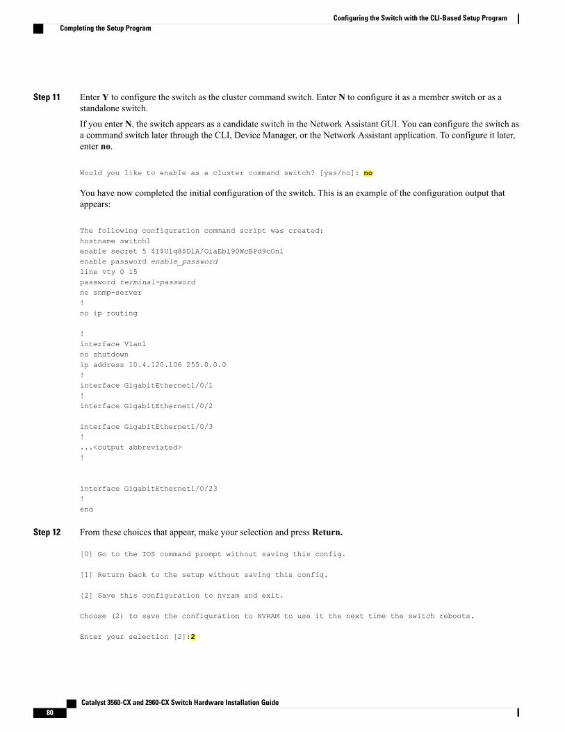
Step 11 Enter Y to configure the switch as the cluster command switch. Enter N to configure it as a member switch or as astandalone switch.
If you enter N, the switch appears as a candidate switch in the Network Assistant GUI. You can configure the switch asa command switch later through the CLI, Device Manager, or the Network Assistant application. To configure it later,enter no.
Would you like to enable as a cluster command switch? [yes/no]: no
You have now completed the initial configuration of the switch. This is an example of the configuration output thatappears:
The following configuration command script was created:hostname switch1enable secret 5 $1$Ulq8$DlA/OiaEbl90WcBPd9cOn1enable password enable_passwordline vty 0 15password terminal-passwordno snmp-server!no ip routing
!interface Vlan1no shutdownip address 10.4.120.106 255.0.0.0!interface GigabitEthernet1/0/1!interface GigabitEthernet1/0/2
interface GigabitEthernet1/0/3!...<output abbreviated>!
interface GigabitEthernet1/0/23!end
Step 12 From these choices that appear, make your selection and press Return.
[0] Go to the IOS command prompt without saving this config.
[1] Return back to the setup without saving this config.
[2] Save this configuration to nvram and exit.
Choose (2) to save the configuration to NVRAM to use it the next time the switch reboots.
Enter your selection [2]:2
Catalyst 3560-CX and 2960-CX Switch Hardware Installation Guide80
Configuring the Switch with the CLI-Based Setup ProgramCompleting the Setup Program

The switch now runs this default configuration. If you want to change this configuration or perform other managementtasks, see Management Options, on page 13.
Catalyst 3560-CX and 2960-CX Switch Hardware Installation Guide 81
Configuring the Switch with the CLI-Based Setup ProgramCompleting the Setup Program

Catalyst 3560-CX and 2960-CX Switch Hardware Installation Guide82
Configuring the Switch with the CLI-Based Setup ProgramCompleting the Setup Program