
catalogue/boring bars.pdf · 2013. 9. 7. · E000 TYPE OF BORING BAR indicates the initial letters...
44
E000 TYPE OF BORING BAR indicates the initial letters for the order number, as well as applicable insert types. LEGEND FOR STOCK STATUS MARK is shown on the left hand page of each double-page spread. MIN. CUTTING DIAMETER is colour-coded to let you find, at a glance, the maximum / minimum cutting diameters for internal machining. REFERENCE PAGE FOR APPLICABLE INSERTS indicates reference pages for details of inserts that are applicable to the title product. PAGE REFERENCE ·SPARE PARTS ·TECHNICAL DATA indicates reference pages, including the above, on the right hand page of each double-page spread. PRODUCT STANDARDS indicates order numbers, stock status (per right/left hand), applicable inserts, dimensions, minimum cutting diameters, standard corner radius, recommended l/d ratios, and spare parts. TITLE OF PRODUCT SERIES PRODUCT SECTION PRODUCT FEATURES FIGURE SHOWING THE TOOLING APPLICATION uses illustrations and arrows to depict available machining applications along with cutting edge lead angles. GEOMETRY CHIP BREAKER BY CUTTING APPLICATION HOW TO READ THE STANDARD OF BORING BARS a How this section page is organized zOrganized by product series. (Refer to the index on the next page.) aTo Order : Please specify zorder number and hand of tool (right/left). E006 E007 95° øD1 RR° Re 5° 95° F1 L2 øD4 H1 L1 95° Re L1 5° L2 F1 95° øD1 RR° H1 øD4 93° 93° Re øD4 H1 L1 L2 5° 93° F1 øD1 RR° Re L1 L2 5° 93° F1 øD1 RR° H1 øD4 FSCLC/P Right hand tool holder shown. FSCLC/P - E Right hand tool holder shown. Order Number Stock Insert Number Dimensions (mm) Min. Cutting Diameter D1 (mm) Standard Corner Radius Re (mm) Recom- mended l/d Ratio * RL D4 L1 L2 F1 H1 RR° Clamp Screw Wrench FSCLC1008R/L-06S aa 0602pp 8 125 18 5 7.2 12 10 0.4 ─3 TS253 TKY08F FSCLP1210R/L-08S aa CPMH NP-CPGB NP-CPMB NP-CPMH 0802pp 10 150 22.5 6 9 5 12 0.4 ─3.5 TS3D TKY10F 1412R/L-08S aa 0802pp 12 150 27 7 11 4 14 0.4 ─4 TS3D TKY10F 1612R/L-09S aa 0903pp 12 150 30 8 11 4 16 0.4 ─4 TS4D TKY15F 1816R/L-09S aa 0903pp 16 180 36 9 15 3.5 18 0.4 ─5 TS4D TKY15F 2220R/L-09S aa 0903pp 20 220 45 11 19 2 22 0.4 ─5 TS4D TKY15F 3025R/L-09S aa 0903pp 25 250 56.3 15 23.4 0 30 0.4 ─5 TS4D TKY15F CCG/MH NP-CCGT NP-CCGW Order Number Stock Insert Number Dimensions (mm) Min. Cutting Diameter D1 (mm) Standard Corner Radius Re (mm) Recom- mended l/d Ratio * RL D4 L1 L2 F1 H1 RR° Clamp Screw Wrench FSCLC1008R/L-06E aa CCGH CCMH NP-CCGT NP-CCGW 0602pp 8 140 13.8 5 7.2 12 10 0.4 ─7 TS253 TKY08F 1008R-06E-2/3 a 0602pp 8 90 13.8 5 7.2 12 10 0.4 ─7 TS253 TKY08F 1008R-06E-1/2 a 0602pp 8 70 13.8 5 7.2 12 10 0.4 ─7 TS253 TKY08F FSCLP1210R/L-08E aa CPMH NP-CPGB NP-CPMB NP-CPMH 0802pp 10 160 16.0 6 9 5 12 0.4 ─7.5 TS3D TKY10F 1210R-08E-2/3 a 0802pp 10 105 16.0 6 9 5 12 0.4 ─7.5 TS3D TKY10F 1210R-08E-1/2 a 0802pp 10 80 16.0 6 9 5 12 0.4 ─7.5 TS3D TKY10F 1412R/L-08E aa 0802pp 12 180 17.8 7 11 4 14 0.4 ─8 TS3D TKY10F 1412R-08E-2/3 a 0802pp 12 120 17.8 7 11 4 14 0.4 ─8 TS3D TKY10F 1412R-08E-1/2 a 0802pp 12 90 17.8 7 11 4 14 0.4 ─8 TS3D TKY10F 1816R/L-09E aa 0903pp 16 220 21.8 9 15 3.5 18 0.4 ─8 TS4D TKY15F 1816R-09E-2/3 a 0903pp 16 145 21.8 9 15 3.5 18 0.4 ─8 TS4D TKY15F 1816R-09E-1/2 a 0903pp 16 110 21.8 9 15 3.5 18 0.4 ─8 TS4D TKY15F 2220R/L-09E aa 0903pp 20 250 24.0 11 19 2 22 0.4 ─8 TS4D TKY15F 2220R-09E-2/3 a 0903pp 20 165 24.0 11 19 2 22 0.4 ─8 TS4D TKY15F 2220R-09E-1/2 a 0903pp 20 125 24.0 11 19 2 22 0.4 ─8 TS4D TKY15F FSTUP Right hand tool holder shown. Order Number Stock Insert Number Dimensions (mm) Min. Cutting Diameter D1 (mm) Standard Corner Radius Re (mm) Recom- mended l/d Ratio * RL D4 L1 L2 F1 H1 RR° Clamp Screw Wrench FSTUP1008R/L-08S aa TPGH TPMH NP-TPGB NP-TPMB NP-TPMH 0802pp 8 125 18 5 7.2 10 10 0.4 ─3 TS2D TKY06F 1210R/L-09S aa 0902pp 10 150 22.5 6 9 8 12 0.4 ─3.5 TS25D TKY08F 1412R/L-09S aa 0902pp 12 150 27 7 11 7 14 0.4 ─4 TS25D TKY08F 1210R/L-11S aa 1103pp 10 150 22.5 6 9 8 12 0.4 ─3.5 TS31D TKY10F 1412R/L-11S aa 1103pp 12 150 27 7 11 7 14 0.4 ─4 TS31D TKY10F 1816R/L-11S aa 1103pp 16 180 36 9 15 4 18 0.4 ─5 TS31D TKY10F 2220R/L-11S aa 1103pp 20 220 45 11 19 0 22 0.4 ─5 TS31D TKY10F 3225R/L-16S aa 1603pp 25 270 56.3 16 23.4 0 32 0.8 ─5 TS4D TKY15F Finish Light Medium FV SV MV (08,09) (08,09,11,16) (08,09,11,16) PCD CBN R/L-F (08,09,11) (08,09,11,16) Order Number Stock Insert Number Dimensions (mm) Min. Cutting Diameter D1 (mm) Standard Corner Radius Re (mm) Recom- mended l/d Ratio * RL D4 L1 L2 F1 H1 RR° Clamp Screw Wrench FSTUP 1008R/L-08E aa TPGH TPMH NP-TPGB NP-TPMB NP-TPMH 0802pp 8 140 13.8 5 7.2 10 10 0.4 ─7 TS2D TKY06F 1008R-08E-2/3 a 0802pp 8 90 13.8 5 7.2 10 10 0.4 ─7 TS2D TKY06F 1008R-08E-1/2 a 0802pp 8 70 13.8 5 7.2 10 10 0.4 ─7 TS2D TKY06F 1210R/L-09E aa 0902pp 10 160 16.0 6 9 8 12 0.4 ─7.5 TS25D TKY08F 1210R-09E-2/3 a 0902pp 10 105 16.0 6 9 8 12 0.4 ─7.5 TS25D TKY08F 1210R-09E-1/2 a 0902pp 10 80 16.0 6 9 8 12 0.4 ─7.5 TS25D TKY08F 1412R/L-09E aa 0902pp 12 180 17.8 7 11 7 14 0.4 ─8 TS25D TKY08F 1412R-09E-2/3 a 0902pp 12 120 17.8 7 11 7 14 0.4 ─8 TS25D TKY08F 1412R-09E-1/2 a 0902pp 12 90 17.8 7 11 7 14 0.4 ─8 TS25D TKY08F 1816R/L-11E aa 1103pp 16 220 21.8 9 15 4 18 0.4 ─8 TS31D TKY10F 1816R-11E-2/3 a 1103pp 16 145 21.8 9 15 4 18 0.4 ─8 TS31D TKY10F 1816R-11E-1/2 a 1103pp 16 110 21.8 9 15 4 18 0.4 ─8 TS31D TKY10F 2220R/L-11E aa 1103pp 20 250 24.0 11 19 0 22 0.4 ─8 TS31D TKY10F 2220R-11E-2/3 a 1103pp 20 165 24.0 11 19 0 22 0.4 ─8 TS31D TKY10F 2220R-11E-1/2 a 1103pp 20 125 24.0 11 19 0 22 0.4 ─8 TS31D TKY10F FSTUP - E Right hand tool holder shown. CCpptype inserts A088─A091 CPpptype inserts A092 CBN & PCD inserts B036─B039, B056 CUTTING CONDITIONS E012 TPpptype inserts A105─A107 SPARE PARTS P001 CBN & PCD inserts B043, B059 TECHNICAL DATA Q001 Finish Light FV SV (06,08,09) (06,08,09) Medium CBN MV (06,08,09) (06,08,09) Finish Light FV SV (06,08,09) (06,08,09) Medium CBN MV (06,08,09) (06,08,09) Finish Light Medium FV SV MV (08,09) (08,09,11) (08,09,11) PCD CBN R/L-F (08,09,11) (08,09,11) BORING BARS BORING BORING DIMPLE BAR aExcellent vibration resistance due to light dimple head. aChip disposal is improved by having two channels for chip evacuation. aA laser printed scale on the side for easy installation (Steel shank). al/d is 3 to 5 times the diameter (Carbide shank is 7 to 8 times the diameter). * Clamp Torque (N • m) : TS253=1.0, TS3D=2.5, TS4D=3.5 * Clamp Torque (N • m) : TS253=1.0, TS3D=2.5, TS4D=3.5 (Note 1) The insert photos are only examples. The letters refer to the chip breaker and the dimension refers to the inscribed circle. (Note 2) When using insert with right and left hand chip breaker, please use left hand insert for right hand holder and right hand insert for left hand holder. * Clamp Torque (N • m) : TS2D=0.6, TS25D=1.0, TS31D=2.5, TS4D=3.5 * Clamp Torque (N • m) : TS2D=0.6, TS25D=1.0, TS31D=2.5 CCooinserts, CPooinserts TPooinserts Carbide shank with coolant hole CCooinserts, CPooinserts Carbide shank with coolant hole TPooinserts FSCLC1008R/L-06S=1° a: Inventory maintained in Japan. FSCLC1008R/L-06E (-2/3, -1/2)=1°
Transcript of catalogue/boring bars.pdf · 2013. 9. 7. · E000 TYPE OF BORING BAR indicates the initial letters...

E000
TYPE OF BORING BARindicates the initial letters for the order number, as well as applicable insert types.
LEGEND FOR STOCK STATUS MARKis shown on the left hand page of each double-page spread.
MIN. CUTTING DIAMETERis colour-coded to let you fi nd, at a glance, the maximum / minimum cutting diameters for internal machining.
REFERENCE PAGE FOR APPLICABLE INSERTSindicates reference pages for details of inserts that are applicable to the title product.
PAGE REFERENCE ·SPARE PARTS·TECHNICAL DATAindicates reference pages, including the above, on the right hand page of each double-page spread.PRODUCT STANDARDS
indicates order numbers, stock status (per right/left hand), applicable inserts, dimensions, minimum cutting diameters, standard corner radius, recommended l/d ratios, and spare parts.
TITLE OF PRODUCT SERIESPRODUCT SECTION PRODUCT FEATURES
FIGURE SHOWING THE TOOLING APPLICATIONuses illustrations and arrows to depict available machining applications along with cutting edge lead angles.
GEOMETRYCHIP BREAKER BY CUTTING APPLICATION
HOW TO READ THE STANDARD OF BORING BARSa How this section page is organizedz Organized by product series.
(Refer to the index on the next page.)
a To Order : Please specifyzorder number and hand of tool (right/left).
E006 E007
95°øD1
RR° Re
5°
95°
F1
L2
øD4
H1L1
95°Re
L15°
L2
F1
95°
øD1
RR° H1
øD4
93°
93°
ReøD4
H1L1
L2
5°
93°
F1
øD1
RR°
Re L1L2
5°
93°
F1
øD1
RR° H1
øD4
FSCLC/P
Right hand tool holder shown.
FSCLC/P-E
Right hand tool holder shown.
Order Number Stock
Insert Number Dimensions (mm)
Min.Cutting
Diameter D1
(mm)
StandardCornerRadius Re
(mm)
Recom-mended
l/dRatio
*
R L D4 L1 L2 F1 H1 RR° ClampScrew Wrench
FSCLC1008R/L-06S a a 0602pp 8 125 18 5 7.2 12 10 0.4 ─3 TS253 TKY08F
FSCLP1210R/L-08S a a
CPMHNP-CPGBNP-CPMBNP-CPMH
0802pp 10 150 22.5 6 9 5 12 0.4 ─3.5 TS3D TKY10F
1412R/L-08S a a 0802pp 12 150 27 7 11 4 14 0.4 ─4 TS3D TKY10F
1612R/L-09S a a 0903pp 12 150 30 8 11 4 16 0.4 ─4 TS4D TKY15F
1816R/L-09S a a 0903pp 16 180 36 9 15 3.5 18 0.4 ─5 TS4D TKY15F
2220R/L-09S a a 0903pp 20 220 45 11 19 2 22 0.4 ─5 TS4D TKY15F
3025R/L-09S a a 0903pp 25 250 56.3 15 23.4 0 30 0.4 ─5 TS4D TKY15F
CCG/MHNP-CCGTNP-CCGW
Order Number Stock
Insert Number Dimensions (mm)
Min.Cutting
Diameter D1
(mm)
StandardCornerRadius Re
(mm)
Recom-mended
l/dRatio
*
R L D4 L1 L2 F1 H1 RR° ClampScrew Wrench
FSCLC1008R/L-06E a a CCGHCCMH
NP-CCGTNP-CCGW
0602pp 8 140 13.8 5 7.2 12 10 0.4 ─7 TS253 TKY08F
1008R-06E-2/3 a 0602pp 8 90 13.8 5 7.2 12 10 0.4 ─7 TS253 TKY08F
1008R-06E-1/2 a 0602pp 8 70 13.8 5 7.2 12 10 0.4 ─7 TS253 TKY08F
FSCLP1210R/L-08E a a
CPMHNP-CPGBNP-CPMBNP-CPMH
0802pp 10 160 16.0 6 9 5 12 0.4 ─7.5 TS3D TKY10F
1210R-08E-2/3 a 0802pp 10 105 16.0 6 9 5 12 0.4 ─7.5 TS3D TKY10F
1210R-08E-1/2 a 0802pp 10 80 16.0 6 9 5 12 0.4 ─7.5 TS3D TKY10F
1412R/L-08E a a 0802pp 12 180 17.8 7 11 4 14 0.4 ─8 TS3D TKY10F
1412R-08E-2/3 a 0802pp 12 120 17.8 7 11 4 14 0.4 ─8 TS3D TKY10F
1412R-08E-1/2 a 0802pp 12 90 17.8 7 11 4 14 0.4 ─8 TS3D TKY10F
1816R/L-09E a a 0903pp 16 220 21.8 9 15 3.5 18 0.4 ─8 TS4D TKY15F
1816R-09E-2/3 a 0903pp 16 145 21.8 9 15 3.5 18 0.4 ─8 TS4D TKY15F
1816R-09E-1/2 a 0903pp 16 110 21.8 9 15 3.5 18 0.4 ─8 TS4D TKY15F
2220R/L-09E a a 0903pp 20 250 24.0 11 19 2 22 0.4 ─8 TS4D TKY15F
2220R-09E-2/3 a 0903pp 20 165 24.0 11 19 2 22 0.4 ─8 TS4D TKY15F
2220R-09E-1/2 a 0903pp 20 125 24.0 11 19 2 22 0.4 ─8 TS4D TKY15F
FSTUP
Right hand tool holder shown.
Order Number Stock
Insert Number Dimensions (mm)
Min.Cutting
Diameter D1
(mm)
StandardCornerRadius Re
(mm)
Recom-mended
l/dRatio
*
R L D4 L1 L2 F1 H1 RR° ClampScrew Wrench
FSTUP1008R/L-08S a a
TPGHTPMH
NP-TPGBNP-TPMBNP-TPMH
0802pp 8 125 18 5 7.2 10 10 0.4 ─3 TS2D TKY06F
1210R/L-09S a a 0902pp 10 150 22.5 6 9 8 12 0.4 ─3.5 TS25D TKY08F
1412R/L-09S a a 0902pp 12 150 27 7 11 7 14 0.4 ─4 TS25D TKY08F
1210R/L-11S a a 1103pp 10 150 22.5 6 9 8 12 0.4 ─3.5 TS31D TKY10F
1412R/L-11S a a 1103pp 12 150 27 7 11 7 14 0.4 ─4 TS31D TKY10F
1816R/L-11S a a 1103pp 16 180 36 9 15 4 18 0.4 ─5 TS31D TKY10F
2220R/L-11S a a 1103pp 20 220 45 11 19 0 22 0.4 ─5 TS31D TKY10F
3225R/L-16S a a 1603pp 25 270 56.3 16 23.4 0 32 0.8 ─5 TS4D TKY15F
Finish Light Medium FV SV MV
(08,09) (08,09,11,16) (08,09,11,16)
PCD CBNR/L-F
(08,09,11) (08,09,11,16)
Order Number Stock
Insert Number Dimensions (mm)
Min.Cutting
Diameter D1
(mm)
StandardCornerRadius Re
(mm)
Recom-mended
l/dRatio
*
R L D4 L1 L2 F1 H1 RR° ClampScrew Wrench
FSTUP 1008R/L-08E a a
TPGHTPMH
NP-TPGBNP-TPMBNP-TPMH
0802pp 8 140 13.8 5 7.2 10 10 0.4 ─7 TS2D TKY06F
1008R-08E-2/3 a 0802pp 8 90 13.8 5 7.2 10 10 0.4 ─7 TS2D TKY06F
1008R-08E-1/2 a 0802pp 8 70 13.8 5 7.2 10 10 0.4 ─7 TS2D TKY06F
1210R/L-09E a a 0902pp 10 160 16.0 6 9 8 12 0.4 ─7.5 TS25D TKY08F
1210R-09E-2/3 a 0902pp 10 105 16.0 6 9 8 12 0.4 ─7.5 TS25D TKY08F
1210R-09E-1/2 a 0902pp 10 80 16.0 6 9 8 12 0.4 ─7.5 TS25D TKY08F
1412R/L-09E a a 0902pp 12 180 17.8 7 11 7 14 0.4 ─8 TS25D TKY08F
1412R-09E-2/3 a 0902pp 12 120 17.8 7 11 7 14 0.4 ─8 TS25D TKY08F
1412R-09E-1/2 a 0902pp 12 90 17.8 7 11 7 14 0.4 ─8 TS25D TKY08F
1816R/L-11E a a 1103pp 16 220 21.8 9 15 4 18 0.4 ─8 TS31D TKY10F
1816R-11E-2/3 a 1103pp 16 145 21.8 9 15 4 18 0.4 ─8 TS31D TKY10F
1816R-11E-1/2 a 1103pp 16 110 21.8 9 15 4 18 0.4 ─8 TS31D TKY10F
2220R/L-11E a a 1103pp 20 250 24.0 11 19 0 22 0.4 ─8 TS31D TKY10F
2220R-11E-2/3 a 1103pp 20 165 24.0 11 19 0 22 0.4 ─8 TS31D TKY10F
2220R-11E-1/2 a 1103pp 20 125 24.0 11 19 0 22 0.4 ─8 TS31D TKY10F
FSTUP-E
Right hand tool holder shown.
CCpp type inserts A088─A091 CPpp type inserts A092 CBN & PCD inserts B036─B039, B056
CUTTING CONDITIONS E012 TPpp type inserts A105─A107 SPARE PARTS P001 CBN & PCD inserts B043, B059 TECHNICAL DATA Q001
Finish Light FV SV
(06,08,09) (06,08,09)
Medium CBNMV
(06,08,09) (06,08,09)
Finish Light FV SV
(06,08,09) (06,08,09)
Medium CBNMV
(06,08,09) (06,08,09)
Finish Light Medium FV SV MV
(08,09) (08,09,11) (08,09,11)
PCD CBNR/L-F
(08,09,11) (08,09,11)
BORING BARS
BO
RIN
G
BO
RIN
G
DIMPLE BAR a Excellent vibration resistance due to light dimple head.a Chip disposal is improved by having two channels for chip evacuation.a A laser printed scale on the side for easy installation (Steel shank).a l/d is 3 to 5 times the diameter (Carbide shank is 7 to 8 times the diameter).
* Clamp Torque (N • m) : TS253=1.0, TS3D=2.5, TS4D=3.5
* Clamp Torque (N • m) : TS253=1.0, TS3D=2.5, TS4D=3.5
(Note 1) The insert photos are only examples. The letters refer to the chip breaker and the dimension refers to the inscribed circle. (Note 2) When using insert with right and left hand chip breaker, please use left hand insert for right hand holder and right hand insert for left hand holder.
* Clamp Torque (N • m) : TS2D=0.6, TS25D=1.0, TS31D=2.5, TS4D=3.5
* Clamp Torque (N • m) : TS2D=0.6, TS25D=1.0, TS31D=2.5
CCooinserts, CPooinserts TPooinserts
Carbide shankwith coolant hole CCooinserts, CPooinserts
Carbide shankwith coolant hole TPooinserts
FSCLC1008R/L-06S=1°
a : Inventory maintained in Japan.
FSCLC1008R/L-06E (-2/3, -1/2)=1°

E001
Appp-DCLNAppp-DDUNAppp-DSKNAppp-DTFNAppp-DVUNAppp-DWLNApppMWLNApppPCLNApppPDQNApppPDUNApppPDZNApppPSKNApppPTFNApppPWLNCpppp-BLSCpppSCLCCpppSCLCCpppSDQCCpppSDUC
CpppSTFCCpppSTUCCpppSVQCCpppSWUBCBCRDPCLDPDHDPDUDPTFDPVPFCTU1FCTU2FSCLC/PFSDQCFSDUCFSTU1FSTU2FSTUP
FSVJB/CFSVPB/CFSVUB/CFSWL1FSWL2FSWUB/PRBHRBHSpppSCLCSpppSCZCSpppSDQCSpppSDUCSpppSSKCSpppSTFCSpppSTFESpppSVQCSpppSVUCSBH
E013E013E014E014E015E015E039E036E037E036E038E035E035E037E022E016E030E031E029
E028E017E032E016E019E020E042E042E041E041E043E026E026E006E009E008E025E025E007
E012E011E011E027E027E010E018E023E030E034E031E029E033E028E040E032E033E024
*Arranged by Alphabetical order
TURNING TOOLS
BORING BARSCLASSIFICATION OF BORING TOOLS ..........IDENTIFICATION ..............................................
STANDARD BORING BARS FEATURES OF DIMPLE BAR ...................... DIMPLE BAR ................................................. DOUBLE CLAMP DIMPLE BAR ................... MICRO-DEX BORING BARS ........................ MICRO-MINI TWIN BORING BARS ............. MICRO-MINI BORING BARS ........................ F TYPE BORING BARS ................................ S TYPE BORING BARS ................................ P TYPE BORING BARS ................................ M TYPE BORING BARS ............................... AL TYPE BORING BARS ............................. D TYPE BORING HEAD ...............................
E002E004
E005E006E013E016E019E022E025E028E035E039E040E041

E002
BORING BARSB
OR
ING
' ' '
DPDU DPTF E041^ E041^
DSKN DTFN E014^ E014^
SWUB STUC
FSTU FCTU
SVUC SDUC STFC SSKC
FSTUP FSDUC FSVUB/C
DDUN DVUN
PDUN PTFN PSKN
STFE
CppFR-BLS
E016^
E040^
E035^
E033^ E028^ E029^ E033^
E025^ E026^
E013^ E015^
E007^ E008^ E011^
E035^ E036^
E022^
E017^
'=75° '=91°
90°
'=93°
CLASSIFICATION
(Note 1) Holders with blue colour symbol have an anti-vibration carbide shank. (For Micro-dex boring bars, carbide shank only.)
Name of Tool Holder Features
MICRO-MINI Boring Bars
MICRO-MINI TWIN Boring Bars
MICRO-DEX Boring Bars
AL Type Boring Bars
M Type Boring Bars
D Type Boring Head
P Type Boring Bars
S Type Boring Bars
F Type Boring Bars
DOUBLE CLAMPDIMPLE BAR
DIMPLE BAR
(Carbide Shank)
a
a
a
a
a
a
a
a
a
a
a
a
a
a
a
a
a
a
a
a
a
a
a
a
a
a
a
a
a
a
a
a
a
a
a
a
a
a
a
a
a
a
a
a
a
a
a
a
The minimum cutting diameter is from &10.5°, 7°, 11° positive insert.Excellent vibration resistance due to a light dimple head.l/d is 3 to 5 times the diameter (Carbide shank is 7 to 8 times the diameter).The minimum cutting diameter is from &32.Economical negative insert.Single action type.Excellent vibration resistance due to a light dimple head.(With coolant hole.)l/d is 3 to 4 times the diameter.
a
a
a
a
The minimum cutting diameter is from &3.2. Solid carbide type (Single cutting edges).l/d is 5 times the diameter.Cutting edge can be shaped according to the application. Thus, it covers a wide cutting range (threading,grooving,copying, etc.).
The minimum cutting diameter is from &2.2.Solid carbide type with two cutting edges. Continuous cutting from boring to facing.With or without a chip breaker.
The minimum cutting diameter is from &5.7°positive insert.Carbide shank type.Easy-to-use tool geometries.Suitable for small workpieces.l/d is 5 times the diameter.
The minimum cutting diameter is from &20.Suitable for non-ferrous metal.20°positive insert.Screw-on type.l/d is 6 times the diameter.Excellent vibration resistance.
The minimum cutting diameter is from &32.Negative trigon shape insert.Double clamp type.l/d is 3 times the diameter.
The minimum cutting diameter is from &40.Economical negative insert.Lever lock type.Exchangeable head type.
The minimum cutting diameter is from &25.ISO standard.Economical negative insert.Lever lock type, and pin lock type.l/d is 3 times the diameter.
The minimum cutting diameter is from &5.8.11°positive insert.Screw-on type and Clamp-on type.l/d is 3 to 5 times the diameter.FSWL type is 7°positive insert.
The minimum cutting diameter is from &11.ISO standard.7°positive insert.Screw-on type.l/d is 3 to 5 times the diameter (Carbide shank is 7 times the diameter).

E003
BO
RIN
G
' '
' ' '
CR E020^
DPVP E043^
DPDH DPCL E042^ E042^
DWLN DCLN E015^ E013^
e e e
u
e
u u
u u
u e
e
e e
e
u
e
e e e
e e
e e
e u
e u e
e
FSDQC FSCLC/P FSWUB/P FSVPB/C FSVJB/C
FSWL
SCLC SDQC SVQC SCZC
PDZN PDQN PWLN PCLN
MWLN
SCLC
CBppRS(-B) E019^
E016^
E039^
E036^ E037^ E037^ E038^
E034^ E032^ E031^ E030^
E027^
E009^ E011^ E012^ E006^ E010^
'=95° '=142° '=107°30´─117°30´ '=3°, 5° '=93°
* *
**
*
(Note 2) e : 1st recommendation. u : 2nd recommendation.(Note 3) *Indicates that the shank material is carbide.
Selection Standard
Eco
nom
ical
Low
Cuttin
g Res
ist-
ance
(Sha
rpnes
s)
Clam
p Ri
gidity
Vib
ratio
n R
esis
tanc
eO
pera
tion
Effi
cien
cy
Coo
lant
Hol
e
Spe
cial
ized
Smal
l Dia
met
er
Cutti
ng

E004
BORING BARSB
OR
ING
08 08
L3
06 07
11 11
04
08 09
16 16 06
11 09 1/2
8 140
90 70
12 180 120
90
16 220 145 110
20 250
125 165
10 160 105
80 2/3
93°
5° 7°
11°
95°
142°
107°30´ 117°30´
– –
– –
– – –
– –
–
L R
F S
S E
L Q P J
U D T V W
C
C P
B
08 10 12 16 20 25 32
8 10 12 16 20 25 32
10 12 13 14 16 18 20
10 12 13 14 16 18 20
22 25 30 32 34 40
22 25 30 32 34 40
z x c v b n m , .
91° 6.35 06 07
11 11
9.525 09 11
16 09
16
12.70 12 15
22 12
19.05 19
19
7.94 08 75°
95°
93° 107°30´
S 16 M S C L C R 09
L R
P S
M D S T V W
C
K L Q U
F
E N P
C F H K M Q R S T U V
80 100 125 150 180 200 250 300 350 400
08 10 12 16 20 25 32 40
8 10 12 16 20 25 32 40
–
– – – –
– – – –
y
y
z x c v b n m
, . / u
F S C C L 08 10 06 2/3 R - - E 11
4.76 6.35 7.94 9.525 5.56
A
C
E
S
IDENTIFICATIONDIMPLE BAR
zShank Material
xShank Diameter (mm)
cTool Length(mm) vClamp Structure bInsert Shape mInsert Clearance ,Hand of Tool
.Cutting Edge Length (mm)nCutting Angle
xClamp Structure
,Hand of Tool
zFunction
/Shank Material.Cutting Edge Length (mm) Tool Length (Carbide shank only) (mm)
cInsert Shape vCutting Angle
bInsert Clearance
mShank Diameter (mm)
nMin.Cutting Diameter (mm)
u11
Fix type Screw-on
RHOMBIC 80°RHOMBIC 55°
TRIGON
TRIANGULAR 60°RHOMBIC 35°
Right HandLeft Hand
Inscribed circle of insert
TRIANGULAR 60°RHOMBIC 35°
RHOMBIC 80°RHOMBIC 55°
TRIGON
Steel ShankCarbide Shank Shank Dia.
No symbol
ISO TYPE Boring tools [For Aluminium Alloy, M-type, P-type and S-type]
Carbide Shank
Steel Shank
Double ClampLever LockScrew-on
RHOMBIC 80°RHOMBIC 55°
RHOMBIC 35°
SQUARE 90°TRIANGULAR 60°
Inscribed circle of insert
SQUARE 90°TRIANGULAR 60°
RHOMBIC 80°RHOMBIC 55°
RHOMBIC 35°
Steel Shankwith Coolant Hole
Carbide Shankwith Coolant Hole
Right HandLeft Hand
7°Positive20°Positive
11°Positive0°
Trigon

E005
BO
RIN
G
CCG/MT0602pp (&6.35)
CPG/MT0802pp (&7.94)
CPG/MT0903pp (&9.525)
CPMX0802pp (&7.94)
CPMX0903pp (&9.525)
TPG/MX0802pp (&4.76)
TPG/MX0902pp (&5.56)
TPG/MX1103pp (&9.525)
y
y
y
FEATURES OF DIMPLE BAR
DEFLECTION RESISTANCE VIBRATION RESISTANCE
aDIMPLE BAR
aConventional Product
28.3!m
70.1g 20ms
49.7g 15.8ms
34!m
Highly rigid steel shank and a lightweight head configuration designed by computer simulation analysis reduces chatter and improves the vibration damping properties.
Chip disposal is improved by having two channels for chip evacuation.
The lightweight head with its large dimple reduces chatter.
Available in sizes smaller than the ISO standard. Therefore the boring of small diameter holes is possible.
The boring bar has a laser printed scale on the shank to facilitate easy installation.
"F and FS" breakers improves the quality of the surface finish, "MV" breaker offers excellent chip disposal. High wear resistant CBN inserts are also available for the machining of hardened materials.
Cutting Force(Principal Force)
Cutting Force(Back Force)
The unique cross sectional shape engineered into the dimple effectively balances the cutting forces (principal and back force), and reduces deflection by up to 17 %.
By reducing the weight of the head, the damping properties are increased.
Weight of the Head Damping Time
Weight of the Head Damping Time
Boring Bar DeflectionDIMPLE BAR
Conventional Bar
*The simulation data stated above was conducted with a FSCLP1816R-09S holder, under the following conditions; l/d=5, depth of cut=0.5mm, and feed=0.05mm/rev.
Direction for the use of CCG/MT • CPG/MT • CPMX • TPG/MX type inserts By changing the clamp screw, it is possible to use the inserts listed in the table below.
Holder : FSCLC/P • FSCLC/P...E Holder : FSTUP • FSTUP...EInsert Number Clamp Screw Insert Number Clamp Screw
*If the screw is too long then please shorten as necessary.(Note) TPMT/W09,W11 types cannot be used due to a different clamp screw size.
Can be used as it is.
Change to TS3
Change to TS4
Can be used as it is.
Can be used as it is.
Change to CS200T
Change to CS250T
Change to CS300890T

E006
95°øD1
RR° Re
5°
95°
F1
L2
øD4
H1L1
95°Re
L15°
L2
F1
95°
øD1
RR° H1
øD4
FSCLC/P
Right hand tool holder shown.
FSCLC/P-E
Right hand tool holder shown.
Order Number Stock
Insert Number Dimensions (mm)
Min.Cutting
Diameter D1
(mm)
StandardCornerRadius Re
(mm)
Recom-mended
l/dRatio
*
R L D4 L1 L2 F1 H1 RR° ClampScrew Wrench
FSCLC1008R/L-06S a a 0602pp 8 125 18 5 7.2 12 10 0.4 ─3 TS253 TKY08F
FSCLP1210R/L-08S a a
CPMHNP-CPGBNP-CPMBNP-CPMH
0802pp 10 150 22.5 6 9 5 12 0.4 ─3.5 TS3D TKY10F
1412R/L-08S a a 0802pp 12 150 27 7 11 4 14 0.4 ─4 TS3D TKY10F
1612R/L-09S a a 0903pp 12 150 30 8 11 4 16 0.4 ─4 TS4D TKY15F
1816R/L-09S a a 0903pp 16 180 36 9 15 3.5 18 0.4 ─5 TS4D TKY15F
2220R/L-09S a a 0903pp 20 220 45 11 19 2 22 0.4 ─5 TS4D TKY15F
3025R/L-09S a a 0903pp 25 250 56.3 15 23.4 0 30 0.4 ─5 TS4D TKY15F
CCG/MHNP-CCGTNP-CCGW
Order Number Stock
Insert Number Dimensions (mm)
Min.Cutting
Diameter D1
(mm)
StandardCornerRadius Re
(mm)
Recom-mended
l/dRatio
*
R L D4 L1 L2 F1 H1 RR° ClampScrew Wrench
FSCLC1008R/L-06E a a CCGHCCMH
NP-CCGTNP-CCGW
0602pp 8 140 13.8 5 7.2 12 10 0.4 ─7 TS253 TKY08F
1008R-06E-2/3 a 0602pp 8 90 13.8 5 7.2 12 10 0.4 ─7 TS253 TKY08F
1008R-06E-1/2 a 0602pp 8 70 13.8 5 7.2 12 10 0.4 ─7 TS253 TKY08F
FSCLP1210R/L-08E a a
CPMHNP-CPGBNP-CPMBNP-CPMH
0802pp 10 160 16.0 6 9 5 12 0.4 ─7.5 TS3D TKY10F
1210R-08E-2/3 a 0802pp 10 105 16.0 6 9 5 12 0.4 ─7.5 TS3D TKY10F
1210R-08E-1/2 a 0802pp 10 80 16.0 6 9 5 12 0.4 ─7.5 TS3D TKY10F
1412R/L-08E a a 0802pp 12 180 17.8 7 11 4 14 0.4 ─8 TS3D TKY10F
1412R-08E-2/3 a 0802pp 12 120 17.8 7 11 4 14 0.4 ─8 TS3D TKY10F
1412R-08E-1/2 a 0802pp 12 90 17.8 7 11 4 14 0.4 ─8 TS3D TKY10F
1816R/L-09E a a 0903pp 16 220 21.8 9 15 3.5 18 0.4 ─8 TS4D TKY15F
1816R-09E-2/3 a 0903pp 16 145 21.8 9 15 3.5 18 0.4 ─8 TS4D TKY15F
1816R-09E-1/2 a 0903pp 16 110 21.8 9 15 3.5 18 0.4 ─8 TS4D TKY15F
2220R/L-09E a a 0903pp 20 250 24.0 11 19 2 22 0.4 ─8 TS4D TKY15F
2220R-09E-2/3 a 0903pp 20 165 24.0 11 19 2 22 0.4 ─8 TS4D TKY15F
2220R-09E-1/2 a 0903pp 20 125 24.0 11 19 2 22 0.4 ─8 TS4D TKY15F
CCpp type inserts A088─A091 CPpp type inserts A092 CBN & PCD inserts B036─B039, B056
Finish Light FV SV
(06,08,09) (06,08,09)
Medium CBNMV
(06,08,09) (06,08,09)
Finish Light FV SV
(06,08,09) (06,08,09)
Medium CBNMV
(06,08,09) (06,08,09)
BORING BARSB
OR
ING
DIMPLE BAR a Excellent vibration resistance due to light dimple head.a Chip disposal is improved by having two channels for chip evacuation.a A laser printed scale on the side for easy installation (Steel shank).a l/d is 3 to 5 times the diameter (Carbide shank is 7 to 8 times the diameter).
* Clamp Torque (N • m) : TS253=1.0, TS3D=2.5, TS4D=3.5
* Clamp Torque (N • m) : TS253=1.0, TS3D=2.5, TS4D=3.5
(Note 1) The insert photos are only examples. The letters refer to the chip breaker and the dimension refers to the inscribed circle. (Note 2) When using insert with right and left hand chip breaker, please use left hand insert for right hand holder and right hand insert for left hand holder.
CCooinserts, CPooinserts
Carbide shankwith coolant hole CCooinserts, CPooinserts
FSCLC1008R/L-06S=1°
a : Inventory maintained in Japan.
FSCLC1008R/L-06E (-2/3, -1/2)=1°

E007
93°
93°
ReøD4
H1L1
L2
5°
93°
F1
øD1
RR°
Re L1L2
5°
93°
F1
øD1
RR° H1
øD4
FSTUP
Right hand tool holder shown.
Order Number Stock
Insert Number Dimensions (mm)
Min.Cutting
Diameter D1
(mm)
StandardCornerRadius Re
(mm)
Recom-mended
l/dRatio
*
R L D4 L1 L2 F1 H1 RR° ClampScrew Wrench
FSTUP1008R/L-08S a a
TPGHTPMH
NP-TPGBNP-TPMBNP-TPMH
0802pp 8 125 18 5 7.2 10 10 0.4 ─3 TS2D TKY06F
1210R/L-09S a a 0902pp 10 150 22.5 6 9 8 12 0.4 ─3.5 TS25D TKY08F
1412R/L-09S a a 0902pp 12 150 27 7 11 7 14 0.4 ─4 TS25D TKY08F
1210R/L-11S a a 1103pp 10 150 22.5 6 9 8 12 0.4 ─3.5 TS31D TKY10F
1412R/L-11S a a 1103pp 12 150 27 7 11 7 14 0.4 ─4 TS31D TKY10F
1816R/L-11S a a 1103pp 16 180 36 9 15 4 18 0.4 ─5 TS31D TKY10F
2220R/L-11S a a 1103pp 20 220 45 11 19 0 22 0.4 ─5 TS31D TKY10F
3225R/L-16S a a 1603pp 25 270 56.3 16 23.4 0 32 0.8 ─5 TS4D TKY15F
Finish Light Medium FV SV MV
(08,09) (08,09,11,16) (08,09,11,16)
PCD CBNR/L-F
(08,09,11) (08,09,11,16)
Order Number Stock
Insert Number Dimensions (mm)
Min.Cutting
Diameter D1
(mm)
StandardCornerRadius Re
(mm)
Recom-mended
l/dRatio
*
R L D4 L1 L2 F1 H1 RR° ClampScrew Wrench
FSTUP 1008R/L-08E a a
TPGHTPMH
NP-TPGBNP-TPMBNP-TPMH
0802pp 8 140 13.8 5 7.2 10 10 0.4 ─7 TS2D TKY06F
1008R-08E-2/3 a 0802pp 8 90 13.8 5 7.2 10 10 0.4 ─7 TS2D TKY06F
1008R-08E-1/2 a 0802pp 8 70 13.8 5 7.2 10 10 0.4 ─7 TS2D TKY06F
1210R/L-09E a a 0902pp 10 160 16.0 6 9 8 12 0.4 ─7.5 TS25D TKY08F
1210R-09E-2/3 a 0902pp 10 105 16.0 6 9 8 12 0.4 ─7.5 TS25D TKY08F
1210R-09E-1/2 a 0902pp 10 80 16.0 6 9 8 12 0.4 ─7.5 TS25D TKY08F
1412R/L-09E a a 0902pp 12 180 17.8 7 11 7 14 0.4 ─8 TS25D TKY08F
1412R-09E-2/3 a 0902pp 12 120 17.8 7 11 7 14 0.4 ─8 TS25D TKY08F
1412R-09E-1/2 a 0902pp 12 90 17.8 7 11 7 14 0.4 ─8 TS25D TKY08F
1816R/L-11E a a 1103pp 16 220 21.8 9 15 4 18 0.4 ─8 TS31D TKY10F
1816R-11E-2/3 a 1103pp 16 145 21.8 9 15 4 18 0.4 ─8 TS31D TKY10F
1816R-11E-1/2 a 1103pp 16 110 21.8 9 15 4 18 0.4 ─8 TS31D TKY10F
2220R/L-11E a a 1103pp 20 250 24.0 11 19 0 22 0.4 ─8 TS31D TKY10F
2220R-11E-2/3 a 1103pp 20 165 24.0 11 19 0 22 0.4 ─8 TS31D TKY10F
2220R-11E-1/2 a 1103pp 20 125 24.0 11 19 0 22 0.4 ─8 TS31D TKY10F
FSTUP-E
Right hand tool holder shown.
CUTTING CONDITIONS E012 TPpp type inserts A105─A107 SPARE PARTS P001 CBN & PCD inserts B043, B059 TECHNICAL DATA Q001
Finish Light Medium FV SV MV
(08,09) (08,09,11) (08,09,11)
PCD CBNR/L-F
(08,09,11) (08,09,11)
BO
RIN
G
* Clamp Torque (N • m) : TS2D=0.6, TS25D=1.0, TS31D=2.5, TS4D=3.5
* Clamp Torque (N • m) : TS2D=0.6, TS25D=1.0, TS31D=2.5
TPooinserts
Carbide shankwith coolant hole TPooinserts

E008
93°Re
øD4
H1
L1
F2
L2
0°
F1
93°
øD1
RR°
93°
93°
RR°
øD1
F1
L2 L1
F2
0°
H1
øD4Re
Order Number Stock
Insert Number Dimensions (mm)
Min.Cutting
Diameter D1
(mm)
StandardCornerRadius Re
(mm)
Recom-mended
l/dRatio
*
R L D4 L1 L2 F1 F2 H1 RR° ClampScrew Wrench
FSDUC1410R/L-07S a a DCMTDCETDCGT
NP-DCMTNP-DCMW
0702pp 10 150 18 8.3 3.3 9 7.5 14 0.4 ─3.5 TS25 TKY08F
1612R/L-07S a a 0702pp 12 150 20 9.3 3.3 11 6 16 0.4 ─4 TS25 TKY08F
2016R/L-07S a a 0702pp 16 180 20 11.3 3.3 15 5 20 0.4 ─5 TS25 TKY08F
3220R/L-11S a a 11T3pp 20 180 22.5 16.1 6.1 19 5 32 0.8 ─5 TS43 TKY15F
Order Number Stock
Insert Number Dimensions (mm)
Min.Cutting
Diameter D1
(mm)
StandardCornerRadius Re
(mm)
Recom-mended
l/dRatio
*
R L D4 L1 L2 F1 F2 H1 RR° ClampScrew Wrench
FSDUC1410R/L-07E a a DCMTDCETDCGT
NP-DCMTNP-DCMW
0702pp 10 160 16.0 8.3 3.3 9 7.5 14 0.4 ─7.5 TS25 TKY08F
1612R/L-07E a a 0702pp 12 180 17.8 9.3 3.3 11 6.0 16 0.4 ─8 TS25 TKY08F
2016R/L-07E a a 0702pp 16 220 21.8 11.3 3.3 15 5.0 20 0.4 ─8 TS25 TKY08F
3220R/L-11E a a 11T3pp 20 250 24.0 16.1 6.1 19 5.0 32 0.8 ─8 TS43 TKY15F
FSDUC
Right hand tool holder shown.
FSDUC-E
Right hand tool holder shown.
DCpp type inserts A093─A096 CBN & PCD inserts B040, B041, B057
Finish Light Medium FV SV MV
(07,11) (07,11) (07,11)
Medium PCD CBN Standard R/L-F
(07,11) (07,11) (07,11)
Finish Light Medium FV SV MV
(07,11) (07,11) (07,11)
Medium PCD CBN Standard R/L-F
(07,11) (07,11) (07,11)
BORING BARSB
OR
ING
* Clamp Torque (N • m) : TS25=1.0, TS43=3.5
* Clamp Torque (N • m) : TS25=1.0, TS43=3.5
DCooinserts
Carbide shankwith coolant hole DCooinserts
DIMPLE BAR a Excellent vibration resistance due to light dimple head.a Chip disposal is improved by having two channels for chip evacuation.a A laser printed scale on the side for easy installation (Steel shank).a l/d is 3 to 5 times the diameter (Carbide shank is 7 to 8 times the diameter).
a : Inventory maintained in Japan.
(Note 1) The insert photos are only examples. The letters refer to the chip breaker and the dimension refers to the inscribed circle. (Note 2) When using insert with right and left hand chip breaker, please use left hand insert for right hand holder and right hand insert for left hand holder.

E009
107°30´
øD4
H1
L1L2
F2
0°
F1
107°30´
øD1
RR°Re
107°30´
107°30´
F1
L2 L1
F2
øD1
RR°
0°
H1
øD4Re
Order Number Stock
Insert Number Dimensions (mm)
Min.Cutting
Diameter D1
(mm)
StandardCornerRadius Re
(mm)
Recom-mended
l/dRatio
*
R L D4 L1 L2 F1 F2 H1 RR° ClampScrew Wrench
FSDQC1310R/L-07S a a DCMTDCETDCGT
NP-DCMTNP-DCMW
0702pp 10 150 20.5 7.6 2.6 9 8 13 0.4 ─3.5 TS25 TKY08F
1612R/L-07S a a 0702pp 12 150 22.5 8.6 2.6 11 6 16 0.4 ─4 TS25 TKY08F
2016R/L-07S a a 0702pp 16 180 22.5 10.6 2.6 15 5 20 0.4 ─5 TS25 TKY08F
2520R/L-11S a a 11T3pp 20 180 26 13.7 3.7 19 7 25 0.8 ─5 TS43 TKY15F
Order Number Stock
Insert Number Dimensions (mm)
Min.Cutting
Diameter D1
(mm)
StandardCornerRadius Re
(mm)
Recom-mended
l/dRatio
*
R L D4 L1 L2 F1 F2 H1 RR° ClampScrew Wrench
FSDQC1310R/L-07E a a DCMTDCETDCGT
NP-DCMTNP-DCMW
0702pp 10 162 18.4 7.6 2.6 9 8 13 0.4 ─7.5 TS25 TKY08F
1612R/L-07E a a 0702pp 12 182 20.2 8.6 2.6 11 6 16 0.4 ─8 TS25 TKY08F
2016R/L-07E a a 0702pp 16 222 24.2 10.6 2.6 15 5 20 0.4 ─8 TS25 TKY08F
2520R/L-11E a a 11T3pp 20 254 28.0 13.7 3.7 19 7 25 0.8 ─8 TS43 TKY15F
FSDQC
Right hand tool holder shown.
FSDQC-E
Right hand tool holder shown.
CUTTING CONDITIONS E012 DCpp type inserts A093─A096 SPARE PARTS P001 CBN & PCD inserts B040, B041, B057 TECHNICAL DATA Q001
Finish Light Medium FV SV MV
(07,11) (07,11) (07,11)
Medium PCD CBN Standard R/L-F
(07,11) (07,11) (07,11)
Finish Light Medium FV SV MV
(07,11) (07,11) (07,11)
Medium PCD CBN Standard R/L-F
(07,11) (07,11) (07,11)
BO
RIN
G
* Clamp Torque (N • m) : TS25=1.0, TS43=3.5
* Clamp Torque (N • m) : TS25=1.0, TS43=3.5
DCooinserts
Carbide shankwith coolant hole DCooinserts

E010
93°
93°L1
L2 H1
93°
5°F1
øD4øD1
RR° Re
93°
F1
L2
L1
RR°øD1
5°
H1
øD4Re
Order Number Stock
Insert Number Dimensions (mm)
Min.Cutting
Diameter D1
(mm)
StandardCornerRadius Re
(mm)
Recom-mended
l/dRatio
*
R L D4 L1 L2 F1 H1 RR° ClampScrew Wrench
FSWUB1008R/L-L3S a a WBMTWBGT
L302pp 8 125 18 5 7.2 14 10 0.2 ─3 TS2 TKY06F
1210R/L-L3S a a L302pp 10 150 22.5 6 9 11 12 0.2 ─3.5 TS2 TKY06F
FSWUP1412R/L-04S a a
WPMTWPGT
0402pp 12 150 27 7 11 4 14 0.4 ─4 TS253 TKY08F
1816R/L-04S a a 0402pp 16 180 36 9 15 1 18 0.4 ─5 TS253 TKY08F
2220R/L-06S a a 0603pp 20 220 45 11 19 2 22 0.8 ─5 TS4 TKY15F
3025R/L-06S a a 0603pp 25 250 56.3 15 23.4 0 30 0.8 ─5 TS4 TKY15F
Order Number Stock
Insert Number Dimensions (mm)
Min.Cutting
Diameter D1
(mm)
StandardCornerRadius Re
(mm)
Recom-mended
l/dRatio
*
R L D4 L1 L2 F1 H1 RR° ClampScrew Wrench
FSWUB 1008R/L-L3E a a
WBMTWBGT
L302pp 8 140 13.8 5 7.2 14 10 0.2 ─7 TS2 TKY06F
1008R-L3E-2/3 a L302pp 8 90 13.8 5 7.2 14 10 0.2 ─7 TS2 TKY06F
1008R-L3E-1/2 a L302pp 8 70 13.8 5 7.2 14 10 0.2 ─7 TS2 TKY06F
1210R/L-L3E a a L302pp 10 160 16.0 6 9 11 12 0.2 ─7.5 TS2 TKY06F
1210R-L3E-2/3 a L302pp 10 105 16.0 6 9 11 12 0.2 ─7.5 TS2 TKY06F
1210R-L3E-1/2 a L302pp 10 80 16.0 6 9 11 12 0.2 ─7.5 TS2 TKY06F
FSWUP 1412R/L-04E a a
WPMTWPGT
0402pp 12 180 17.8 7 11 4 14 0.4 ─8 TS253 TKY08F
1412R-04E-2/3 a 0402pp 12 120 17.8 7 11 4 14 0.4 ─8 TS253 TKY08F
1412R-04E-1/2 a 0402pp 12 90 17.8 7 11 4 14 0.4 ─8 TS253 TKY08F
1816R/L-04E a a 0402pp 16 220 21.8 9 15 1 18 0.4 ─8 TS253 TKY08F
1816R-04E-2/3 a 0402pp 16 145 21.8 9 15 1 18 0.4 ─8 TS253 TKY08F
1816R-04E-1/2 a 0402pp 16 110 21.8 9 15 1 18 0.4 ─8 TS253 TKY08F
2220R/L-06E a a 0603pp 20 250 24.0 11 19 2 22 0.8 ─8 TS4 TKY15F
2220R-06E-2/3 a 0603pp 20 165 24.0 11 19 2 22 0.8 ─8 TS4 TKY15F
2220R-06E-1/2 a 0603pp 20 125 24.0 11 19 2 22 0.8 ─8 TS4 TKY15F
FSWUB/P
Right hand tool holder shown.
FSWUB/P-E
Right hand tool holder shown.
WBpp type inserts A113 WPpp type inserts A115 PCD inserts B062
Finish R/L-F·FS
(L3,04,06)
Medium MV
(L3,04,06)
Finish R/L-F·FS
(L3,04,06)
Medium MV
(L3,04,06)
BORING BARSB
OR
ING
* Clamp Torque (N • m) : TS2=0.6, TS253=1.0, TS4=3.5
* Clamp Torque (N • m) : TS2=0.6, TS253=1.0, TS4=3.5
WBooinserts, WPooinserts
Carbide shankwith coolant hole WBooinserts, WPooinserts
The &8 and &10 shanks are 0°
The &8 and &10 shanks are 0°
DIMPLE BAR a Excellent vibration resistance due to light dimple head.a Chip disposal is improved by having two channels for chip evacuation.a A laser printed scale on the side for easy installation (Steel shank).a l/d is 3 to 5 times the diameter (Carbide shank is 7 to 8 times the diameter).
a : Inventory maintained in Japan.
(Note 1) The insert photos are only examples. The letters refer to the chip breaker and the dimension refers to the inscribed circle. (Note 2) When using insert with right and left hand chip breaker, please use left hand insert for right hand holder and right hand insert for left hand holder.

E011
117°30´
93°
117°30´
L2L1
F1
øD4
5°
øD1
RR°
F2 H1Re
93°
L2L1
F1
F2
øD1
RR°
H1øD4
0°
Re
FSVUB/C
Right hand tool holder shown.
FSVPB/C
Right hand tool holder shown.
Order Number Stock
Insert Number Dimensions (mm)
Min.Cutting
Diameter D1
(mm)
StandardCornerRadius Re
(mm)
Recom-mended
l/dRatio
*
R L D4 L1 L2 F1 F2 H1 RR° Shim Shim Pin ClampScrew Wrench
FSVUC1612R/L-08S a a 0802pp 12 150 25 11 5.5 11 8 16 0.4 ─4 ─ ─ TS202 TKY06F
FSVUB2016R/L-11S a a
VBETVBGTVBMT
NP-VBGW
1103pp 16 180 32.5 15.5 8 15 8 20 0.4 ─5 ─ ─ TS255 TKY08F
2520R/L-11S a a 1103pp 20 200 40.5 17.5 8 19 7 25 0.4 ─5 ─ ─ TS255 TKY08F
3425R/L-16S a a 1604pp 25 220 50 20.5 8.5 23.4 13 34 0.8 ─5 SPSVN32 BCP141 TS35D TKY15F
4032R/L-16S a a 1604pp 32 250 84.0 27.5 12 30.4 9 40 0.8 ─5 SPSVN32 BCP141 TS35D TKY15F
VCGTVCMT
Order Number Stock
Insert Number Dimensions (mm)
Min.Cutting
Diameter D1
(mm)
StandardCornerRadius Re
(mm)
Recom-mended
l/dRatio
*
R L D4 L1 L2 F1 F2 H1 RR° Shim Shim Pin ClampScrew Wrench
FSVPC1610R/L-08S a a 0802pp 10 150 25 8 3 9 8 16 0.4 ─3.5 ─ ─ TS202 TKY06F
FSVPB2012R/L-11S a a
VBETVBGTVBMT
NP-VBGW
1103pp 12 150 28 10 4.5 11 8 20 0.4 ─4 ─ ─ TS255 TKY08F
2516R/L-11S a a 1103pp 16 180 35 12.5 5 15 5 25 0.4 ─5 ─ ─ TS255 TKY08F
3020R/L-11S a a 1103pp 20 200 40 15 5 19 5 30 0.4 ─5 ─ ─ TS255 TKY08F
3425R/L-16S a a 1604pp 25 220 50 17 5 23.4 13 34 0.8 ─5 SPSVN32 BCP141 TS35D TKY15F
4032R/L-16S a a 1604pp 32 250 55 22 6.5 30.4 9 40 0.8 ─5 SPSVN32 BCP141 TS35D TKY15F
VCGTVCMT
Finish Medium FV MV
(08,11,16) (08,11,16)
Medium CBN Standard
(16) (16)
VBpp type inserts A108, A109 CUTTING CONDITIONS E012 VCpp type inserts A110 SPARE PARTS P001 CBN & PCD inserts B045, B061 TECHNICAL DATA Q001
Finish Medium FV MV
(08,11,16) (08,11,16)
Medium CBN Standard
(16) (16)
BO
RIN
G
* Clamp Torque (N • m) : TS202=0.6, TS255=1.0, TS35D=3.5
* Clamp Torque (N • m) : TS202=0.6, TS255=1.0, TS35D=3.5
VCooinserts, VBooinserts
VCooinserts, VBooinserts

E012
142° 142°
L3L1
H1øD4
5°øD1
RR°
F1
Re
FSVJB/C
Right hand tool holder shown.
Order Number Stock
Insert Number Dimensions (mm)
Min.Cutting
Diameter D1
(mm)
StandardCornerRadius Re
(mm)
Recom-mended
l/dRatio
*
R L D4 L1 L3 F1 H1 RR° ClampScrew Wrench
FSVJC1612R/L-08S a a VCGTVCMT
0802pp 12 150 26 2 11 5 16 0.4 ─4 TS202 TKY06F
2016R/L-08S a a 0802pp 16 180 36 2 15 5 20 0.4 ─5 TS202 TKY06F
FSVJB2520R/L-11S a a VBETVBGTVBMT
1103pp 20 200 37.5 2 19 5 25 0.4 ─5 TS255 TKY08F
3025R/L-11S a a 1103pp 25 250 45 3.5 23.4 5 30 0.4 ─5 TS255 TKY08F
Work Material CuttingMode Breaker Recom-
mendation Grade Cutting Speed (m/min)
l/d < 3 (Steel shank)l/d < 6 (Carbide shank) l/d = 4─5 (Steel shank)
l/d = 7─8 (Carbide shank) Feed
(mm/rev) Depth of Cut
(mm) Feed
(mm/rev) Depth of Cut
(mm)
P
Mild Steel <180HB
Finish FV z NX2525 170 (120─220) 0.10 (0.05─0.15) ─0.5 0.10 (0.05─0.15) ─0.5
Light SVz NX3035 150 (100─200) 0.20 (0.10─0.25) ─1.0 0.15 (0.05─0.20) ─1.0
x NX2525 160 (110─210) 0.20 (0.10─0.25) ─1.0 0.15 (0.05─0.20) ─1.0
Medium MVz NX3035 140 (90─190) 0.25 (0.15─0.35) ─2.0 0.20 (0.15─0.25) ─1.5
x NX2525 150 (100─200) 0.25 (0.15─0.35) ─2.0 0.20 (0.15─0.25) ─1.5
Carbon SteelAlloy Steel 180─350HB
Finish FVz VP15TF 140 (90─190) 0.10 (0.05─0.15) ─0.5 0.10 (0.05─0.15) ─0.5
x NX2525 130 (80─180) 0.10 (0.05─0.15) ─0.5 0.10 (0.05─0.15) ─0.5
Light SVz UE6020 140 (90─190) 0.20 (0.10─0.25) ─1.0 0.15 (0.05─0.20) ─1.0
x NX3035 110 (60─160) 0.20 (0.10─0.25) ─1.0 0.15 (0.05─0.20) ─1.0
Medium MVz UE6020 130 (80─180) 0.25 (0.15─0.35) ─2.0 0.20 (0.15─0.25) ─1.5x NX3035 100 (60─150) 0.25 (0.15─0.35) ─2.0 0.20 (0.15─0.25) ─1.5
M
Stainless Steel <200HB
Finish FV z VP15TF 150 (110─190) 0.10 (0.05─0.15) ─0.5 0.10 (0.05─0.15) ─0.5
Light SVz US735 125 (85─165) 0.20 (0.10─0.25) ─1.0 0.15 (0.05─0.20) ─1.0
x VP15TF 130 (90─170) 0.20 (0.10─0.25) ─1.0 0.15 (0.05─0.20) ─1.0
Medium MVz US735 105 (70─135) 0.20 (0.15─0.25) ─2.0 0.20 (0.15─0.25) ─1.0x VP15TF 120 (80─160) 0.20 (0.15─0.25) ─2.0 0.20 (0.15─0.25) ─1.0
K Gray Cast IronTensile Strength
<350MPa
Finish F, FS z HTi10 130 (90─160) 0.15 (0.10─0.20) ─0.5 0.15 (0.10─0.20) ─0.5
Medium MV z VP15TF 90 (60─120) 0.20 (0.15─0.25) ─2.0 0.20 (0.15─0.25) ─1.5
N Aluminium Alloy Finish
F, FS z HTi10 300 (200─400) 0.10 (0.05─0.15) ─0.5 0.10 (0.05─0.15) ─0.5 Flat Top z MD220 200 (150─250) 0.10 (0.05─0.15) ─2.0 0.10 (0.05─0.15) ─1.0
H Heat Treated Steel 35─65HRC Finish Flat Top z MB825 100 (80─200) 0.10 (0.05─0.15) ─0.15 0.10 (0.05─0.15) ─0.1
VBpp type inserts A108, A109 VCpp type inserts A110 CBN inserts B045
Finish FV
(08,11,16)
Medium MV
(08,11)
BORING BARSB
OR
ING
* Clamp Torque (N • m) : TS202=0.6, TS255=1.0
(Note 1) When vibrations occur, reduce cutting speed by 30%.(Note 2) The depth of cut needs to be less than the corner diameter when using the FSVJ type.
VCooinserts, VBooinserts
RECOMMENDED CUTTING CONDITIONS
DIMPLE BAR a Excellent vibration resistance due to light dimple head.a Chip disposal is improved by having two channels for chip evacuation.a A laser printed scale on the side for easy installation (Steel shank).a l/d is 3 to 5 times the diameter.
a : Inventory maintained in Japan.
(Note 1) The insert photos are only examples. The letters refer to the chip breaker and the dimension refers to the inscribed circle. (Note 2) When using insert with right and left hand chip breaker, please use left hand insert for right hand holder and right hand insert for left hand holder.

E013
95°
93°
øD4
H1RR°
Re
L1
L3
F1
95°
ReL1
L3
F1
93°
RR°
øD1
6°
øD1
6°øD4
H1
DCLN
Right hand tool holder shown.
DDUN
Right hand tool holder shown.
Order Number Stock
Insert Number Dimensions (mm)
Min.
Cuttin
gDi
amete
r
D1
Standa
rdCo
rner R
adius
Re
*
R L D4 L1 L3 F1 H1 RR° Shim Shim Pin ClampBridge Spring Clamp
Screw Wrench (mm) (mm)
A25R-DCLNR/L12 a a CNMACNMGCNMMCNGG
1204pp 25 200 40 17 23 11 32 0.8 LLSCP42 LLP14 DCK2613 DCS1 DC0621T TKY20F
A32S-DCLNR/L12 a a 1204pp 32 250 50 22 30 13 40 0.8 LLSCN42 LLP14 DCK2613 DCS1 DC0621T TKY20F
A40T-DCLNR/L12 a a 1204pp 40 300 63 27 37 10 50 0.8 LLSCN42 LLP14 DCK2613 DCS1 DC0621T TKY20F
Order Number Stock
Insert Number Dimensions (mm)
Min.
Cuttin
gDi
amete
r
D1
Standa
rdCo
rner R
adius
Re
*
R L D4 L1 L3 F1 H1 RR° Shim Shim Pin ClampBridge Spring Clamp
Screw Wrench (mm) (mm)
A25R-DDUNR/L15 a a DNMADNMGDNMXDNGADNGG
1504pp 25 200 40 17 23 13 32 0.8 LLSDP42 LLP14 DCK2613 DCS1 DC0621T TKY20F
A32S-DDUNR/L15 a a 1504pp 32 250 50 22 30 13 40 0.8 LLSDN42 LLP14 DCK2613 DCS1 DC0621T TKY20F
A40T-DDUNR/L15 a a 1504pp 40 300 63 27 37 10 50 0.8 LLSDN42 LLP14 DCK2613 DCS1 DC0621T TKY20F
Work Material Hardness CuttingMode
l/d<3 l/d=3─4
Cutting Speed (m/min)
Feed (mm/rev)
Depth of Cut (mm)
Cutting Speed (m/min)
Feed (mm/rev)
Depth of Cut (mm)
P Carbon SteelAlloy Steel 180─350HB Medium 110 (80─140) 0.25 (0.1─0.4) ─5.0 110 (80─140) 0.2 (0.1─0.3) ─4.0
M Stainless Steel <200HB Medium 80 (60─100) 0.2 (0.1─0.3) ─4.0 70 (50─100) 0.15 (0.1─0.25) ─3.0
K Gray Cast Iron Tensile Strength <350MPa Medium 80 (60─100) 0.25 (0.1─0.4) ─5.0 80 (60─100) 0.2 (0.1─0.3) ─4.0
CNpp type inserts A058─A062 DNpp type inserts A063─A067 SPARE PARTS P001 CBN & PCD inserts B022─B026, B052 TECHNICAL DATA Q001
Finish Light Light Medium FH SA SH MP
(12) (12) (12) (12)
Medium Medium Stainless CBNMH Standard MS
(12) (12) (12) (12)
Finish Light Medium Medium FH SH MP MH
(15) (15) (15) (15)
Medium Stainless G Class CBN Standard MS R/L
(15) (15) (15) (15)
BO
RIN
G
* Clamp Torque (N • m) : DC0621T=5.0
* Clamp Torque (N • m) : DC0621T=5.0
a Economical negative insert.a Single action type.a Excellent vibration resistance due to a light dimple head. (With coolant hole.)a l/d is 3 to 4 times the diameter.
With coolant hole CNooinserts
With coolant hole DNooinserts
RECOMMENDED CUTTING CONDITIONS
DOUBLECLAMP DIMPLE BAR

E014
75°
91°
øD4
H1Re
L1
L3
F1
75°
RR°
øD4
H1RR°
Re
L1
L3
F1
91°
øD1
6°
6°
øD1
DSKN
Right hand tool holder shown.
DTFN
Right hand tool holder shown.
Order Number Stock
Insert Number Dimensions (mm)
Min.
Cuttin
gDi
amete
r
D1
Standa
rdCo
rner R
adius
Re
*
R L D4 L1 L3 F1 H1 RR° Shim Shim Pin ClampBridge Spring Clamp
Screw Wrench (mm) (mm)
A25R-DSKNR/L12 a a 1204pp 25 200 40 17 23 13 32 0.8 LLSSP42 LLP14 DCK2613 DCS1 DC0621T TKY20F
A32S-DSKNR/L12 a a 1204pp 32 250 50 22 30 13 40 0.8 LLSSN42 LLP14 DCK2613 DCS1 DC0621T TKY20F
SNMASNMGSNMMSNGASNGG
Order Number Stock
Insert Number Dimensions (mm)
Min.
Cuttin
gDi
amete
r
D1
Standa
rdCo
rner R
adius
Re
*
R L D4 L1 L3 F1 H1 RR° Shim Shim Pin ClampBridge Spring Clamp
Screw Wrench (mm) (mm)
A25R-DTFNR/L16 a a 1604pp 25 200 40 17 23 13 32 0.8 LLSTP32 LLP23 DCK2211 DCS2 DC0520T TKY15F
A32S-DTFNR/L16 a a 1604pp 32 250 50 22 30 13 40 0.8 LLSTN32 LLP23 DCK2211 DCS2 DC0520T TKY15F
TNMATNMGTNMMTNGATNGG
SNpp type inserts A069─A073 TNpp type inserts A074─A079 CBN & PCD inserts B027─B029, B053
Finish Light Medium Medium FH SH MP MH
(12) (12) (12) (12)
Medium Stainless G Class CBN Standard MS R/L
(12) (12) (12) (12)
Finish Light Medium Medium FH SH MP MH
(16) (16) (16) (16)
Medium Stainless G Class CBN Standard MS R/L
(16) (16) (16) (16)
BORING BARSB
OR
ING
* Clamp Torque (N • m) : DC0621T=5.0
* Clamp Torque (N • m) : DC0520T=3.5
With coolant hole SNooinserts
With coolant hole TNooinserts
a Economical negative insert.a Single action type.a Excellent vibration resistance due to a light dimple head. (With coolant hole.)a l/d is 3 to 4 times the diameter.
DOUBLECLAMP DIMPLE BAR
a : Inventory maintained in Japan.
(Note 1) The insert photos are only examples. The letters refer to the chip breaker and the dimension refers to the inscribed circle. (Note 2) When using insert with right and left hand chip breaker, please use left hand insert for right hand holder and right hand insert for left hand holder.

E015
øD4
H1ReL1
L3
F1
93°
RR°
øD1
5°
øD4
H1ReL1
L3
F1
95°
RR°
øD1
6°
93°
95°
DVUN
Right hand tool holder shown.
DWLN
Right hand tool holder shown.
Order Number Stock
Insert Number Dimensions (mm)
Min.
Cuttin
gDi
amete
r
D1
Standa
rdCo
rner R
adius
Re
*
R L D4 L1 L3 F1 H1 RR° Shim Shim Pin ClampBridge Spring Clamp
Screw Wrench (mm) (mm)
A40T-DVUNR/L16 a a 1604pp 40 300 63 27 37 9 50 0.8 DCSVN32 LLP13 DCK3113 DCS2 DC0520T TKY15FVNMAVNGA
Order Number Stock
Insert Number Dimensions (mm)
Min.
Cuttin
gDi
amete
r
D1
Standa
rdCo
rner R
adius
Re
*
R L D4 L1 L3 F1 H1 RR° Shim Shim Pin ClampBridge Spring Clamp
Screw Wrench (mm) (mm)
A25R-DWLNR/L06 a a WNMG 0604pp 25 200 40 17 23 13 32 0.8 LLSWP32 LLP23 DCK2211 DCS2 DC0520T TKY15F
A25R-DWLNR/L08 a a
WNMAWNMG
0804pp 25 200 40 17 23 13 32 0.8 LLSWP42 LLP14 DCK2613 DCS1 DC0621T TKY20F
A32S-DWLNR/L08 a a 0804pp 32 250 50 22 30 13 40 0.8 LLSWN42 LLP14 DCK2613 DCS1 DC0621T TKY20F
A40T-DWLNR/L08 a a 0804pp 40 300 63 27 37 10 50 0.8 LLSWN42 LLP14 DCK2613 DCS1 DC0621T TKY20F
Work Material Hardness CuttingMode
l/d<3 l/d=3─4
Cutting Speed (m/min)
Feed (mm/rev)
Depth of Cut (mm)
Cutting Speed (m/min)
Feed (mm/rev)
Depth of Cut (mm)
P Carbon SteelAlloy Steel 180─350HB Medium 110 (80─140) 0.25 (0.1─0.4) ─5.0 110 (80─140) 0.2 (0.1─0.3) ─4.0
M Stainless Steel <200HB Medium 80 (60─100) 0.2 (0.1─0.3) ─4.0 70 (50─100) 0.15 (0.1─0.25) ─3.0
K Gray Cast Iron Tensile Strength <350MPa Medium 80 (60─100) 0.25 (0.1─0.4) ─5.0 80 (60─100) 0.2 (0.1─0.3) ─4.0
VNpp type inserts A080, A081 WNpp type inserts A082─A084 SPARE PARTS P001 CBN & PCD inserts B030, B031, B054 TECHNICAL DATA Q001
Finish Light Medium Medium FH SH MP MH
(16) (16) (16) (16)
Medium Stainless G Class CBN Standard MS R/L
(16) (16) (16) (16)
Finish Light Medium Medium FH SH MP MH
(08) (06,08) (06,08) (08)
Medium Medium ─Semi-Heavy Stainless
Standard GH MS
(08) (08) (06,08)
BO
RIN
G
* Clamp Torque (N • m) : DC0520T=3.5
* Clamp Torque (N • m) : DC0520T=3.5, DC0621T=5.0
With coolant hole VNooinserts
With coolant hole WNooinserts
RECOMMENDED CUTTING CONDITIONS

E016
93°
95°L1
øD4
H1
F1
95°
øD1
RR°Re
øD4
H1L1
RR°øD1
F1
93°
Re
Order Number
Sto
ck
Insert Number Dimensions (mm)
Min.Cutting
Diameter D1
(mm)
StandardCornerRadius
Re(mm)
* 2
R D4 L1 F1 H1 RR° ClampScrew Wrench
C04GSCLCR03 a
CCGTNP-CCMW
03S1ppL-F 4 90 2.5 3.7 15 5 0.2 TS16 TKY06F
C05HSCLCR03 a 03S1ppL-F 5 100 3.0 4.7 13 6 0.2 TS16 TKY06F
C06JSCLCR04 a 04T0ppL-F 6 110 3.5 5.7 13 7 0.2 TS21 TKY08F
C07KSCLCR04 a 04T0ppL-F 7 125 4.0 6.7 11 8 0.2 TS21 TKY08F
* 1
Order Number
Sto
ck
Insert Number Dimensions (mm)
Min.Cutting
Diameter D1
(mm)
StandardCornerRadius
Re(mm)
*
R D4 L1 F1 H1 RR° ClampScrew Wrench
C05HSWUBR02 a
WBGT
0201ppL-F 5 100 3.0 4.7 15 6 0.2 TS21 TKY06F
C06JSWUBR02 a 0201ppL-F 6 110 3.5 5.7 13 7 0.2 TS2C TKY06F
C07KSWUBRL3 a L302ppL-F 7 125 4.0 6.7 15 8 0.2 TS2 TKY06F
SCLC
Right hand tool holder only.
SWUB
Right hand tool holder only.
CCGT type inserts A088 WBGT type inserts A113 CBN & PCD inserts B038, B056
Finish L-F
(03,04)
PCD/CBN
(03,04)
Finish L-F
(02,L3)
BORING BARSB
OR
ING
a : Inventory maintained in Japan.
MICRO-DEX BORING BARS
a The minimum cutting diameter is from &5.a 7° positive insert, carbide shank type.a Easy-to-use tool geometries.a Suitable for small workpieces.
a l/d is 5 times the diameter.
* Clamp Torque (N • m) : TS21=0.6, TS2C=0.6, TS2=0.6
Carbide shank CCooinserts
Carbide shank WBGT inserts
(Note) The insert photos are only examples. The letters refer to the chip breaker and the dimension refers to the inscribed circle.
*1 Diameter of inscribed circle is special. (For SCLC type)
*2 Clamp Torque (N • m) : TS16=0.6, TS21=0.6

E017
93°
H1
øD4
L1
F1
øD1
RR°
93°
27°
0.35Re
Order Number
Sto
ck
Insert Number Dimensions (mm)
Min.Cutting
Diameter D1
(mm)
StandardCornerRadius
Re(mm)
*
R D4 L1 F1 H1 RR° ClampScrew Wrench
C07KSTUCR06 a TCGT 0601ppL-F 7 125 4.0 6.7 12 8 0.2 TS2C TKY06F
STUC
Depth of cut is limited when cutting backwards. Right hand tool holder only.
Work Material Grade Cutting Speed (m/min)
Feed (mm/rev)
Depth of Cut (mm) l/d
P Carbon Steel, Alloy Steel 180─350HB NX2525 80 (40─120) 0.03 (0.01─0.05) 0.2 (0.1─0.3) 3─5
M Stainless Steel <200HB VP15TF 80 (40─120) 0.03 (0.01─0.05) 0.2 (0.1─0.3) 3─5
K Gray Cast Iron <350MPa VP15TF 80 (40─120) 0.03 (0.01─0.05) 0.2 (0.1─0.3) 3─5
N Non-Ferrous Meterial
VP15TF 120 (80─160) 0.05 (0.01─0.08) 0.4 (0.1─0.6) 3─5
MD220 120 (80─160) 0.05 (0.01─0.08) 0.4 (0.1─0.6) 3─5
H Heat Treated Steel 35─65HRC MB810 80 (40─120) 0.03 (0.01─0.05) 0.1 (0.03─0.2) 3─5
TCGT type inserts A103 SPARE PARTS P001 TECHNICAL DATA Q001
Finish L-F
(06)
BO
RIN
G
* Clamp Torque (N • m) : TS2C=0.6
Carbide shank TCGT inserts
RECOMMENDED CUTTING CONDITIONS

E018
øD5
5
10L1
S1 S2 3-M4 x 0.7
z
øD8
L1
øD5
10
20S3
vz x c
øD4
5 S1 S2 3-M4 x 0.7
x c
Order Number S
tock
Dimensions (mm) MICRO-DEX * 1 Clamp Screw
Wrench Torque(N • m) D4 D8 D5 L1 S1 S2 S3 z x c v
RBH 15840N a 15.875 4 15 100 15 15 ─ C04GSpppRpp A A A ─ HKY20F 2.0 15850N a 15.875 5 15 100 15 15 ─ C05HSpppRpp A A A ─ HKY20F 2.0 15860N a 15.875 6 15 100 15 15 ─ C06JSpppRpp A A A ─ HKY20F 2.0 15870N a 15.875 7 15 100 20 20 ─ C07KSpppRpp A A A ─ HKY20F 2.0RBH 1640N a 16 4 15 100 15 15 ─ C04GSpppRpp A A A ─ HKY20F 2.0 1650N a 16 5 15 100 15 15 ─ C05HSpppRpp A A A ─ HKY20F 2.0 1660N a 16 6 15 100 15 15 ─ C06JSpppRpp A A A ─ HKY20F 2.0 1670N a 16 7 15 100 20 20 ─ C07KSpppRpp A A A ─ HKY20F 2.0
* 2 RBH19040N a 19.05 4 18 125 15 15 ─ C04GSpppRpp B B B ─ HKY20F 2.0
* 2 19050N a 19.05 5 18 125 15 15 ─ C05HSpppRpp B B B ─ HKY20F 2.0
* 2 19060N a 19.05 6 18 125 15 15 ─ C06JSpppRpp B B B ─ HKY20F 2.0
* 2 19070N a 19.05 7 18 125 20 20 ─ C07KSpppRpp B B B ─ HKY20F 2.0RBH 2040N a 20 4 13 125 15 15 ─ C04GSpppRpp A B B ─ HKY20F 2.0 2050N a 20 5 14 125 15 15 ─ C05HSpppRpp A B B ─ HKY20F 2.0 2060N a 20 6 15 125 15 15 ─ C06JSpppRpp A B B ─ HKY20F 2.0 2070N a 20 7 16 125 20 20 ─ C07KSpppRpp A B B ─ HKY20F 2.0RBH 2240N a 22 4 13 125 15 15 12.5 C04GSpppRpp A B B A HKY20F 2.0 2250N a 22 5 14 125 15 15 12.5 C05HSpppRpp A B B A HKY20F 2.0 2260N a 22 6 15 125 15 15 15 C06JSpppRpp A B B A HKY20F 2.0 2270N a 22 7 16 125 20 20 15 C07KSpppRpp A B B A HKY20F 2.0RBH 2540N a 25 4 13 150 15 15 ─ C04GSpppRpp A C C ─ HKY20F 2.0 2550N a 25 5 14 150 15 15 ─ C05HSpppRpp A C C ─ HKY20F 2.0 2560N a 25 6 15 150 15 15 ─ C06JSpppRpp A C C ─ HKY20F 2.0 2570N a 25 7 16 150 20 20 ─ C07KSpppRpp A C C ─ HKY20F 2.0RBH 25440N a 25.4 4 13 150 15 15 ─ C04GSpppRpp A C C ─ HKY20F 2.0 25450N a 25.4 5 14 150 15 15 ─ C05HSpppRpp A C C ─ HKY20F 2.0 25460N a 25.4 6 15 150 15 15 ─ C06JSpppRpp A C C ─ HKY20F 2.0 25470N a 25.4 7 16 150 20 20 ─ C07KSpppRpp A C C ─ HKY20F 2.0
Conventional OrderNumber
Revised OrderNumber
RBH1940N RBH19040N1950N 19050N1960N 19060N1970N 19070N
BORING BARSB
OR
ING
*1 Order number of clamp screw A=HSS04004, B=HSS04006, C=HSS04008
*2 Revised order number.
RBH22ppN has a temporary set screw for different machine specifi cations. (Represented by number 4)
RBH158ppN, RBH16ppN,RBH190ppN
STANDARD HOLDER
MICRO-DEX BORING BARS
a : Inventory maintained in Japan. (MICRO-MINI TWIN is available in 1 piece in one pack.)

E019
H1øD4
Re±0.015
Z
5° 5°
F1
F2
L1L2
L3
Order Number Stock
Breaker Min.
Cutting Diameter (mm)
Dimensions (mm) MicroGrain Coated TF15 VP15TF l/d<3 l/d>3 Re D4 L1 L2 L3 F1 F2 H1 Z
CB02RS a a without 2.2 3.6 0.05 2 50 5 6 1 0.25 1.8 1.402RS-B a a with 2.2 3.9 0.05 2 50 5 6 1 0.25 1.8 1.402RS-01 a a without 2.2 3.6 0.1 2 50 5 6 1 0.25 1.8 1.402RS-01B a a with 2.2 4.2 0.1 2 50 5 6 1 0.25 1.8 1.402RS-02 a a without 2.2 3.6 0.2 2 50 5 6 1 0.25 1.8 1.402RS-02B a a with 2.2 4.9 0.2 2 50 5 6 1 0.25 1.8 1.403RS a a without 3.2 4.2 0.05 3 50 7.5 9 1.5 0.35 2.7 2.303RS-B a a with 3.2 4.4 0.05 3 50 7.5 9 1.5 0.35 2.7 2.303RS-01 a a without 3.2 4.2 0.1 3 50 7.5 9 1.5 0.35 2.7 2.303RS-01B a a with 3.2 4.5 0.1 3 50 7.5 9 1.5 0.35 2.7 2.303RS-02 a a without 3.2 4.2 0.2 3 50 7.5 9 1.5 0.35 2.7 2.303RS-02B a a with 3.2 4.8 0.2 3 50 7.5 9 1.5 0.35 2.7 2.304RS a a without 4.2 5.1 0.05 4 60 10 12 2 0.45 3.6 3.104RS-B a a with 4.2 5.2 0.05 4 60 10 12 2 0.45 3.6 3.104RS-01 a a without 4.2 5.1 0.1 4 60 10 12 2 0.45 3.6 3.104RS-01B a a with 4.2 5.3 0.1 4 60 10 12 2 0.45 3.6 3.104RS-02 a a without 4.2 5.1 0.2 4 60 10 12 2 0.45 3.6 3.104RS-02B a a with 4.2 5.5 0.2 4 60 10 12 2 0.45 3.6 3.105RS a a without 5.2 6.0 0.05 5 70 12.5 15 2.5 0.55 4.5 3.905RS-B a a with 5.2 6.1 0.05 5 70 12.5 15 2.5 0.55 4.5 3.905RS-02 a a without 5.2 6.0 0.2 5 70 12.5 15 2.5 0.55 4.5 3.905RS-02B a a with 5.2 6.4 0.2 5 70 12.5 15 2.5 0.55 4.5 3.9
CB06RS a a without 6.2 7.2 0.05 6 75 12.5 18 3 0.65 5.4 4.706RS-B a a with 6.2 7.3 0.05 6 75 12.5 18 3 0.65 5.4 4.706RS-02 a a without 6.2 7.2 0.2 6 75 12.5 18 3 0.65 5.4 4.706RS-02B a a with 6.2 7.8 0.2 6 75 12.5 18 3 0.65 5.4 4.7
CB07RS a a without 7.2 8.6 0.05 7 85 12.5 21 3.5 0.75 6.3 5.507RS-B a a with 7.2 8.8 0.05 7 85 12.5 21 3.5 0.75 6.3 5.507RS-02 a a without 7.2 8.6 0.2 7 85 12.5 21 3.5 0.75 6.3 5.507RS-02B a a with 7.2 9.2 0.2 7 85 12.5 21 3.5 0.75 6.3 5.5
CB08RS a a without 8.2 9.5 0.05 8 95 15 24 4 0.85 7.2 6.308RS-B a a with 8.2 9.6 0.05 8 95 15 24 4 0.85 7.2 6.308RS-02 a a without 8.2 9.5 0.2 8 95 15 24 4 0.85 7.2 6.308RS-02B a a with 8.2 9.8 0.2 8 95 15 24 4 0.85 7.2 6.3
CB
Right hand tool only.
Work Material Micro-Mini Twin CB Micro-Mini Twin CR
Cutting Speed (m/min)
Feed (mm/rev)
Depth of Cut (mm) l/d Cutting Speed
(m/min) Feed (mm/rev)
03RS/04RS 05RS
P Carbon Steel Alloy Steel 180─350HB
80(40─120)
0.03 (0.01─0.05)
0.2(0.1─0.3) 3─5 80
(40─120)0.02
(0.01─0.03)0.03
(0.01─0.05)
M Stainless Steel <200HB
80(40─120)
0.03 (0.01─0.05)
0.2(0.1─0.3) 3─5 80
(40─120)0.02
(0.01─0.03)0.03
(0.01─0.05)
K Gray Cast Iron <350MPa
80(40─120)
0.03 (0.01─0.05)
0.2(0.1─0.3) 3─5 80
(40─120)0.03
(0.01─0.05)0.03
(0.01─0.05)
N Non-Ferrous Meterial 120(80─160)
0.05 (0.01─0.08)
0.3(0.1─0.5) 3─5 120
(80─160)0.03
(0.01─0.05)0.05
(0.01─0.08)
TECHNICAL DATA Q001
*
BO
RIN
G
MICRO-MINI TWIN
(Note) Recommend wet machining.
* The Re dimension represents the size before grinding a chip breaker.
For internal machining
RECOMMENDED CUTTING CONDITIONS

E020
Re
L1
H1
L2
L10 øD4øD1
F13°
52°
Order Number Stock
Breaker Min.
Cutting Diameter D1
(mm)
Dimensions (mm) MicroGrain Coated TF15 VP15TF Re D4 L1 L10 L2 F1 H1
CR03RS-01 a a without 3.5 0.1 3 50 8 6 0.15 2.703RS-01B a a with 3.5 0.1 3 50 8 6 0.15 2.704RS-01 a a without 4.5 0.1 4 60 10 7 0.15 3.604RS-01B a a with 4.5 0.1 4 60 10 7 0.15 3.605RS-01 a a without 5.5 0.1 5 70 12 8 0.15 4.505RS-01B a a with 5.5 0.1 5 70 12 8 0.15 4.5
CR
Right hand tool only.
Work Material Micro-Mini Twin CB Micro-Mini Twin CR
Cutting Speed (m/min)
Feed (mm/rev)
Depth of Cut (mm) l/d Cutting Speed
(m/min) Feed (mm/rev)
03RS/04RS 05RS
P Carbon Steel Alloy Steel 180─350HB
80(40─120)
0.03(0.01─0.05)
0.2(0.1─0.3) 3─5 80
(40─120)0.02
(0.01─0.03)0.03
(0.01─0.05)
M Stainless Steel <200HB
80(40─120)
0.03(0.01─0.05)
0.2(0.1─0.3) 3─5 80
(40─120)0.02
(0.01─0.03)0.03
(0.01─0.05)
K Gray Cast Iron <350MPa
80(40─120)
0.03(0.01─0.05)
0.2(0.1─0.3) 3─5 80
(40─120)0.03
(0.01─0.05)0.03
(0.01─0.05)
N Non-Ferrous Meterial 120(80─160)
0.05(0.01─0.08)
0.3(0.1─0.5) 3─5 120
(80─160)0.03
(0.01─0.05)0.05
(0.01─0.08)
BORING BARSB
OR
ING
For internal copying
RECOMMENDED CUTTING CONDITIONS
MICRO-MINI TWIN
a : Inventory maintained in Japan. (MICRO-MINI TWIN is available in 1 piece in one pack.)
(Note 1) Recommend wet machining.(Note 2) The recommended tool overhang of CR type is L10+2mm.

E021 TECHNICAL DATA Q001
BO
RIN
G
1 2 3
3
2
6
R5R5
3
2
6
y
y
PRECAUTIONS WHEN USING THE MICRO-MINI TWIN
aTo avoid chipping of the 2nd cutting edge take care when inserting the boring bar into the holder. Refer to fig.1. If the 2nd edge contacts the internal face of the holder there is a possibility that it may chip.
aWhen installing the boring bar into the holder, tighten the clamp screws after ensuring the flats on the tool holder are parallel to the reference flats on the micro-mini bar. Refer to fig.3.
sMake sure that the clamping screws are tightened to the recommended values.dDo not tighten the clamp screw without a bar in place, otherwise the bridge will be deformed.
sWhen using this type of holder, there is a possibility that damage to the shank and the 2nd cutting edge can occur. Make sure that the clamping screws are tightened to the set torque value. Additionally make sure that there is no clamping screw near the 2nd cutting edge as this can break the boring bar.
eWhen using Mitsubishi holders When using holders with a tool overhang of recommended quantity, ensure that the 3rd clamping
screw is removed prior to machining. (RBH1620N, RBH19020N, RBH2020N and RBH2520N do not have the 3rd screw.) The set torque
value for clamping screw is 2.0 N•m.
aWhen using a holder for general purpose / small automatic lathe:
aWhen using a square type holder:
Internal face of the holder
Insert directionCutting edge
3rd clamping screw
2nd cutting edgeInsert point
Insert The reference plane of square type holder
Tighten the clamping screw ensuring makingthe micro-mini twin boring bars in contact withthe reference plane of square type holder.
Fig.1
Fig.2
Fig.3
MACHINING METHODS OF THE CR TYPEaProfile turning
<Cutting Conditions>Workpiece : JIS S20CHolder : CR05RS-01BCutting Speed : 80m/minFeed : 0.05mm/revDepth of Cut : 0.05mmWet Cutting
Machining a work piecewithout a pre-prepared hole
a Inner end facing
NOTES FOR USE
<Cutting Conditions>Workpiece : JIS S20CHolder : CR05RS-01BCutting Speed : 80m/minFeed : 0.05mm/revDepth of Cut : 0.05mmWet Cutting
Depth of Cut
Depth of Cut Depth of Cut
Depth of Cut
Depth of Cut
Machining a work piecewith a pre-prepared hole
By drilling a pre-prepared hole, the machining time will be shortened and chip control will be improved.
By drilling a pre-prepared hole, the machining time will be shortened and chip control will be improved.
Machining a work piecewithout a pre-prepared hole
Machining a work piecewith a pre-prepared hole
The cutting edgeshould not be
cross the centreline of the
work piece.
Profile turning,Inner end facing
The depth of cutshould be smaller
than the cornerradius value.
Copying
If the cutting edge crosses the centre line of awork piece, the cutting edge can fracture.
With depths of cut larger than thecorner radius value, burrs will be formed.

E022
W3 F2
L2L1
øD4øD
4øD44°
Work Material Cutting Speed (m/min)
Feed (mm/rev)
Depth of Cut (mm) l/d Edge Condition (mm)
* Corner Radius or C * Honing
P Carbon Steel, Alloy Steel 180─350HB 40 (30─50) 0.05 (─0.1) 0.2 (0.1─0.3) 5 0.1─0.5 0.01─0.05
M Stainless Steel <200HB 40 (30─50) 0.05 (─0.1) 0.2 (0.1─0.3) 5 <0.4 <0.03
(Honing not required)
K Gray Cast Iron <350MPa 40 (30─50) 0.05 (─0.05) 0.2 (0.1─0.3) 5 0.1─0.5 0.01─0.05
N Non-Ferrous Meterial 80 (60─100) 0.05 (─0.1) 0.3 (0.1─0.5) 5 0.1─0.5 <0.03 (Honing not required)
Order Number Stock Dimensions (mm)
Min.Cutting
Diameter
(mm)
Max. Depth of Groove
F2(mm)
Geometry
TF15 W3 D4 L1 L2
C03FR-BLS a 2.0 3 80 15 3.2 1.0
Right hand tool only.
C04FR-BLS a 2.5 4 80 20 4.2 1.5
C05HR-BLS a 3.0 5 100 25 5.2 2.0
BORING BARSB
OR
ING
0.5–0.8 4° w
25°
20°
4°
6°
35°
19° 19°
60° 4°
6°
0.5–0.8
25°
20°
1°– 2
°
1°–2°
y GRINDING THE CUTTING EDGE OF MICRO-MINI BORING BARa
aMICRO-MINI boring bar can be applied to boring and grooving without any modifications. It can also be reground as shown below.For shaping and regrinding, use a diamond whetstone approximately #250─#400. Please grind according to the application using the figure below as a reference.
(Grinding)
Boring Grooving Threading
App
licat
ion
Grin
ding
Exa
mpl
es
Corner radius
GrindingGrinding
Grinding
Grinding
(Grin
ding
)
Double sided relief
Groove widthThread angle
0.3–0.5
MICRO-MINI BORING BARS
a Solid carbide type with minimum cutting diameter &3.2mm.a l/d is 5 times the diameter.a Cutting edge can be shaped according to the application thus, it covers a wide application range (threading, grooving, copying, etc).
RECOMMENDED CUTTING CONDITIONS
STANDARD MICRO-MINI BORING BARS (Solid carbide boring bar)
Shank diameterFlat area
Flat area
a : Inventory maintained in Japan. (MICRO MINI is available in 1 piece in one pack.)
*Cutting edge is not honed. Please hone according to the workpiece before machining.

E023 SPARE PARTS P001 TECHNICAL DATA Q001
Order Number
Sto
ck
Dimensions (mm) Micro-MiniC
Micro-Mini Twin * 1 Clamp Screw Wrench Torque
(N • m) D4 D8 D5 L1 S1 S2 S3 CB CR z x c v
RBH15820N a 15.875 2 15 100 10 ─ ─ ─ ─ B B ─ ─ HKY20F 2.015830N a 15.875 3 15 100 10 10 ─ 03FR-BLS 03RS-01(B) A A A ─ HKY20F 2.015840N a 15.875 4 15 100 15 15 ─ 04FR-BLS 04RS-01(B) A A A ─ HKY20F 2.015850N a 15.875 5 15 100 15 15 ─ 05HR-BLS 05RS-01(B) A A A ─ HKY20F 2.015860N a 15.875 6 15 100 15 15 ─ ─ ─ A A A ─ HKY20F 2.015870N a 15.875 7 15 100 20 20 ─ ─ ─ A A A ─ HKY20F 2.015880N a 15.875 8 15 100 20 20 ─ ─ ─ D D D ─ HKY20F 2.0
RBH1620N a 16 2 15 100 10 ─ ─ ─ ─ B B ─ ─ HKY20F 2.01630N a 16 3 15 100 10 10 ─ 03FR-BLS 03RS-01(B) A A A ─ HKY20F 2.01640N a 16 4 15 100 15 15 ─ 04FR-BLS 04RS-01(B) A A A ─ HKY20F 2.01650N a 16 5 15 100 15 15 ─ 05HR-BLS 05RS-01(B) A A A ─ HKY20F 2.01660N a 16 6 15 100 15 15 ─ ─ ─ A A A ─ HKY20F 2.01670N a 16 7 15 100 20 20 ─ ─ ─ A A A ─ HKY20F 2.01680N a 16 8 15 100 20 20 ─ ─ ─ D D D ─ HKY20F 2.0
* 2 RBH19020N a 19.05 2 18 125 10 ─ ─ ─ ─ C C ─ ─ HKY20F 2.0
* 2 19030N a 19.05 3 18 125 10 10 ─ 03FR-BLS 03RS-01(B) B B B ─ HKY20F 2.0
* 2 19040N a 19.05 4 18 125 15 15 ─ 04FR-BLS 04RS-01(B) B B B ─ HKY20F 2.0
* 2 19050N a 19.05 5 18 125 15 15 ─ 05HR-BLS 05RS-01(B) B B B ─ HKY20F 2.0
* 2 19060N a 19.05 6 18 125 15 15 ─ ─ ─ B B B ─ HKY20F 2.0
* 2 19070N a 19.05 7 18 125 20 20 ─ ─ ─ B B B ─ HKY20F 2.0 19080N a 19.05 8 18 125 20 20 ─ ─ ─ A A A ─ HKY20F 2.0
RBH2020N a 20 2 11 125 10 ─ ─ ─ ─ A A ─ ─ HKY20F 2.02030N a 20 3 12 125 10 10 ─ 03FR-BLS 03RS-01(B) A A B ─ HKY20F 2.02040N a 20 4 13 125 15 15 ─ 04FR-BLS 04RS-01(B) A B B ─ HKY20F 2.02050N a 20 5 14 125 15 15 ─ 05HR-BLS 05RS-01(B) A B B ─ HKY20F 2.02060N a 20 6 15 125 15 15 ─ ─ ─ A B B ─ HKY20F 2.02070N a 20 7 16 125 20 20 ─ ─ ─ A B B ─ HKY20F 2.02080N a 20 8 17 125 20 20 ─ ─ ─ A A A ─ HKY20F 2.0
RBH2220N a 22 2 11 125 10 ─ 10 ─ ─ A B ─ A HKY20F 2.02230N a 22 3 12 125 10 10 10 03FR-BLS 03RS-01(B) A B C A HKY20F 2.02240N a 22 4 13 125 15 15 12.5 04FR-BLS 04RS-01(B) A B B A HKY20F 2.02250N a 22 5 14 125 15 15 12.5 05HR-BLS 05RS-01(B) A B B A HKY20F 2.02260N a 22 6 15 125 15 15 15 ─ ─ A B B A HKY20F 2.02270N a 22 7 16 125 20 20 15 ─ ─ A B B A HKY20F 2.02280N a 22 8 17 125 20 20 15 ─ ─ A B B A HKY20F 2.0
RBH2520N a 25 2 11 150 10 ─ ─ ─ ─ A B ─ ─ HKY20F 2.02530N a 25 3 12 150 10 10 ─ 03FR-BLS 03RS-01(B) A B C ─ HKY20F 2.02540N a 25 4 13 150 15 15 ─ 04FR-BLS 04RS-01(B) A C C ─ HKY20F 2.02550N a 25 5 14 150 15 15 ─ 05HR-BLS 05RS-01(B) A C C ─ HKY20F 2.02560N a 25 6 15 150 15 15 ─ ─ ─ A C C ─ HKY20F 2.02570N a 25 7 16 150 20 20 ─ ─ ─ A C C ─ HKY20F 2.02580N a 25 8 17 150 20 20 ─ ─ ─ A B B ─ HKY20F 2.0
RBH25420N a 25.4 2 11 150 10 ─ ─ ─ ─ A B ─ ─ HKY20F 2.025430N a 25.4 3 12 150 10 10 ─ 03FR-BLS 03RS-01(B) A B C ─ HKY20F 2.025440N a 25.4 4 13 150 15 15 ─ 04FR-BLS 04RS-01(B) A C C ─ HKY20F 2.025450N a 25.4 5 14 150 15 15 ─ 05HR-BLS 05RS-01(B) A C C ─ HKY20F 2.025460N a 25.4 6 15 150 15 15 ─ ─ ─ A C C ─ HKY20F 2.025470N a 25.4 7 16 150 20 20 ─ ─ ─ A C C ─ HKY20F 2.025480N a 25.4 8 17 150 20 20 ─ ─ ─ A B B ─ HKY20F 2.0
Conventional Order Number Revised Order Number RBH1920N RBH19020N
1930N 19030N1940N 19040N
Conventional Order Number Revised Order Number RBH1950N RBH19050N
1960N 19060N1970N 19070N
02RS(-B)02RS-0p(B)03RS(-B)03RS-0p(B)04RS(-B)04RS-0p(B)05RS(-B)05RS-0p(B)06RS(-B)06RS-0p(B)07RS(-B)07RS-0p(B)08RS(-B)08RS-0p(B)02RS(-B)02RS-0p(B)03RS(-B)03RS-0p(B)04RS(-B)04RS-0p(B)05RS(-B)05RS-0p(B)06RS(-B)06RS-0p(B)07RS(-B)07RS-0p(B)08RS(-B)08RS-0p(B)02RS(-B)02RS-0p(B)03RS(-B)03RS-0p(B)04RS(-B)04RS-0p(B)05RS(-B)05RS-0p(B)06RS(-B)06RS-0p(B)07RS(-B)07RS-0p(B)08RS(-B)08RS-0p(B)02RS(-B)02RS-0p(B)03RS(-B)03RS-0p(B)04RS(-B)04RS-0p(B)05RS(-B)05RS-0p(B)06RS(-B)06RS-0p(B)07RS(-B)07RS-0p(B)08RS(-B)08RS-0p(B)02RS(-B)02RS-0p(B)03RS(-B)03RS-0p(B)04RS(-B)04RS-0p(B)05RS(-B)05RS-0p(B)06RS(-B)06RS-0p(B)07RS(-B)07RS-0p(B)08RS(-B)08RS-0p(B)02RS(-B)02RS-0p(B)03RS(-B)03RS-0p(B)04RS(-B)04RS-0p(B)05RS(-B)05RS-0p(B)06RS(-B)06RS-0p(B)07RS(-B)07RS-0p(B)08RS(-B)08RS-0p(B)02RS(-B)02RS-0p(B)03RS(-B)03RS-0p(B)04RS(-B)04RS-0p(B)05RS(-B)05RS-0p(B)06RS(-B)06RS-0p(B)07RS(-B)07RS-0p(B)08RS(-B)08RS-0p(B)
y
BO
RIN
G
*1 Order number of clamp screw A=HSS04004, B=HSS04006, C=HSS04008, D=HSS04003 *2 Revised order number.
RBH22ppNRBH20ppN, RBH25ppN, RBH254ppNRBH158ppN, RBH16ppN, RBH190ppN
ROUND TYPE HOLDER

E024
B10
10
10020
8
F110
L3
45°
8S2F1
L3
y
Order Number S
tock
Dimensions (mm) Micro-Mini Twin Clamp
Screw Wrench Torque(N • m) F1 L3 S2 B
CB CR CB CR CR CR CB CR
SBH1020R a 13 ─ 6─24 (6─10) ─ ─ 12.9 02RS(-B)02RS-0p(B) ─ HSC04010 HKY30R 4.8
1030R a 14 12.65 8.5─22 (9─15) 11─19.5 (12) 14 13.8 03RS(-B)03RS-0p(B) 03RS-01(B) HSC05012 HKY40R 9.5
1040R a 15 13.15 11─29.5 (12─20) 13─27.5 (14) 15 14.7 04RS(-B)04RS-0p(B) 04RS-01(B) HSC05012 HKY40R 9.5
1050R a 16 13.65 13.5─37 (15─25) 15─35.5 (16) 16 15.6 05RS(-B)05RS-0p(B) 05RS-01(B) HSC05012 HKY40R 9.5
1060R a 17 ─ 13.5─42 (18─30) ─ 17 16.5 06RS(-B)06RS-0p(B) ─ HSC05012 HKY40R 9.5
1070R a 18 ─ 13.5─52 (21─35) ─ 18 17.4 07RS(-B)07RS-0p(B) ─ HSC05012 HKY40R 9.5
*
BORING BARSB
OR
ING
SQUARE TYPE HOLDERCB type (Boring bar fi ts to a holder) CR type (Boring bar fi ts to a holder)
(Note) The MICRO-DEX and the MICRO-MINI cannot be fi t to square holders.
*L3 is the length of overhang for suffi cient clamping, and ( ) is the recommended length for machining of carbon and alloy steel.
(Cla
mp)
MICRO-MINI TWIN
a : Inventory maintained in Japan.

E025
93°øD4
H1
F1
L3
L1
øD1
RR°5°
3°
Re
93°øD4
H1
L1RR°
5°
øD1
3°
F1
L2Re
FSTU1
Right hand tool holder shown.
FSTU2
Right hand tool holder shown.
Order Number Stock
Insert Number Dimensions (mm)
Min.Cutting
Diameter D1
(mm)
StandardCornerRadius Re
(mm)
*
R L D4 L1 L3 F1 H1 RR° Clamp Screw Wrench
FSTU108R/L a a
TPGXTPMX
NP-TPGXNP-TPMX
0802pp 8 125 18 5 7 15 10 0.4 CS200T TKY06F
110R/L a a 0902pp 10 150 22 6 9 13 12 0.4 CS250T TKY08F
112R/L a a 0902pp 12 180 25 8 11 10 16 0.4 CS250T TKY08F
116R/L a a 1103pp 16 200 30 11 14 7 22 0.4 CS300890T TKY08F
Order Number Stock
Insert Number Dimensions (mm)
Min.Cutting
Diameter D1
(mm)
StandardCornerRadius Re
(mm)
*
R L D4 L1 L2 F1 H1 RR° Clamp Screw Wrench
FSTU208R/L a a
TPGXTPMX
NP-TPGXNP-TPMX
0802pp 8 125 13 5 7 15 10 0.4 CS200T TKY06F
210R/L a a 0902pp 10 150 16 6 9 13 12 0.4 CS250T TKY08F
212R/L a a 0902pp 12 180 19 8 11 10 16 0.4 CS250T TKY08F
216R/L a a 1103pp 16 200 26 11 14 7 22 0.4 CS300890T TKY08F
Steel Shank l/d<3 l/d=3─4 (Shank Diameter > 25mm)
Carbide Shank l/d<5 l/d=6─7
Work Material Hardness CuttingMode
Cutting Speed (m/min)
Feed (mm/rev)
Depth of Cut (mm)
Cutting Speed (m/min)
Feed (mm/rev)
Depth of Cut (mm)
P Carbon SteelAlloy Steel 180─350HB
Light Cutting 130 (90─160) 0.1 (0.05─0.15) 0.2 120 (80─150) 0.1 (0.05─0.15) 0.2
Medium Cutting 90 (60─120) 0.25 (0.15─0.35) ─3.0 80 (50─110) 0.15 (0.1─0.2) ─1.5
M Stainless Steel <200HB
Light Cutting 140 (100─180) 0.1 (0.05─0.15) 0.2 140 (100─180) 0.1 (0.05─0.15) 0.2
Medium Cutting 70 (50─90) 0.2 (0.15─0.25) ─2.0 60 (40─80) 0.15 (0.1─0.2) ─1.0
N Aluminium Alloy ─
Light Cutting 300 (200─400) 0.1 (0.05─0.15) 0.2 300 (200─400) 0.1 (0.05─0.15) 0.2
Medium Cutting 200 (150─250) 0.1 (0.05─0.15) ─2.0 200 (150─250) 0.1 (0.05─0.15) ─1.5
TPpp type inserts A106, A107 CBN & PCD inserts B043, B044, B059, B060 SPARE PARTS P001 TECHNICAL DATA Q001
Light Flat Top R/L
(08,09,11) (08,09,11)
PCD CBN/PCDR/L-F
(08,09,11) (11)
Light Flat Top R/L
(08,09,11) (08,09,11)
PCD CBN/PCDR/L-F
(08,09,11) (11)
BO
RIN
G
FTYPE BORING BARS
a The minimum cutting diameter is from &10.a 11°positive insert.a Screw-on type.a l/d is 3 to 5 times the diameter (up to 7 times with the carbide shank).
* Clamp Torque (N • m) : CS200T=0.6, CS250T=1.0, CS300890T=1.0
* Clamp Torque (N • m) : CS200T=0.6, CS250T=1.0, CS300890T=1.0
Carbide shank TPooinserts
TPooinserts
RECOMMENDED CUTTING CONDITIONS
(Note 1) The insert photos are only examples. The letters refer to the chip breaker and the dimension refers to the inscribed circle. (Note 2) When using insert with right and left hand chip breaker, please use left hand insert for right hand holder and right hand insert for left hand holder.

E026
93°øD4
H1
L1
L3
5°RR°
F1øD
1
3°
Re
93°øD4
H1
L1
L3
5°RR°
øD1
F1
3°
Re
Order Number Stock
Insert Number Dimensions (mm)
Min.Cutting
Diameter D1
(mm)
StandardCornerRadius Re
(mm)
*
R L D4 L1 L3 F1 H1 RR° Shim Shim Pin ClampSet
BreakerPiece Wrench
FCTU116R/L a a
TPMNTPMRTPGNTPGR
1103pp 16 200 30 11 14 7 22 0.4 ─ ─ C3 CBT2N HKY25R
120R/L a a 1603pp 20 200 37 13 18 5 26 0.8 ─ ─ C4 CBT3F HKY30R125R/L
(4 Side Flat Shank) a a 1603pp 25 250 40 16 22 5 32 0.8 PT32 BCP202 C4 CBT3F HKY30R132R/L
(4 Side Flat Shank) a a 1603pp 32 300 45 20 29 0 40 0.8 PT32 BCP201 C4 CBT3F HKY30R
Order Number Stock
Insert Number Dimensions (mm)
Min.Cutting
Diameter D1
(mm)
StandardCornerRadius Re
(mm)
*
R D4 L1 L3 F1 H1 RR° Shim Shim Pin ClampSet
BreakerPiece Wrench
FCTU216R a TPMNTPMRTPGNTPGR
1103pp 16 200 26 11 14 7 22 0.4 ─ ─ C3 CBT2N HKY25R
220R a 1603pp 20 200 33 13 18 5 26 0.8 ─ ─ C4 CBT3F HKY30R
225R a 1603pp 25 250 37 16 22 5 32 0.8 PT32 BCP202 C4 CBT3F HKY30R
FCTU1
Right hand tool holder shown.
FCTU2
Right hand tool holder only.
TPpp type inserts A120, A121 CBN & PCD inserts B049, B065
M Class M Class G Class R/L
(11,16) (11,16) (11,16)
G Class CBN/PCD
(11,16) (11,16)
M Class M Class G Class R/L
(11,16) (11,16) (11,16)
G Class CBN/PCD
(11,16) (11,16)
BORING BARSB
OR
ING
* Clamp Torque (N • m) : C3=2.2, C4=3.3
* Clamp Torque (N • m) : C3=2.2, C4=3.3
Carbide shank TPooinserts
TPooinserts
FTYPE BORING BARS
a The minimum cutting diameter is from &22.a 11°positive insert.a Screw-on type.a l/d is 3 to 5 times the diameter (up to 7 times with the carbide shank).
a : Inventory maintained in Japan.
(Note 1) The insert photos are only examples. The letters refer to the chip breaker and the dimension refers to the inscribed circle. (Note 2) When using insert with right and left hand chip breaker, please use left hand insert for right hand holder and right hand insert for left hand holder.

E027
95°
95°
øD1
RR°
F1
95°
L3
L1 øD4
H1
L3
Re
95°
RR°
øD1
F1
L3
L1 øD4
H1
L3
Re
FSWL108R/LS108R/LM
FSWL208R/LS208R/LM
FSWL1
Right hand tool holder shown.
FSWL2
Right hand tool holder shown.
Order Number Stock
Insert Number Dimensions (mm)
Min.Cutting
Diameter D1
(mm)
StandardCornerRadius Re
(mm)
*
R L D4 L1 L3 F1 H1 RR° Clamp Screw Wrench
FSWL108R/LS a a 0201pp 8 100 19 2.9 7 17 5.8 0.4 TS21 TKY06F
108R/LM a a L302pp 8 100 25 4 7 15 8 0.4 TS2 TKY06F
108R/L a a
WCMTWCMW
0402pp 8 125 10 5 7 15 10 0.4 TS25 TKY08F
110R/L a a 0402pp 10 150 12 6 9 13 12 0.4 TS25 TKY08F
112R/L a a 06T3pp 12 180 15 8 11 13 16 0.8 TS4 TKY15F
116R/L a a 06T3pp 16 200 20 11 14 7 22 0.8 TS4 TKY15F
WCMTWCGTWCMTWCGTWCMW
Order Number Stock
Insert Number Dimensions (mm)
Min.Cutting
Diameter D1
(mm)
StandardCornerRadius Re
(mm)
*
R L D4 L1 L3 F1 H1 RR° Clamp Screw Wrench
FSWL208R/LS a a 0201pp 8 122 25 2.9 7 17 5.8 0.4 TS21 TKY06F
208R/LM a a L302pp 8 125 33 4 7 15 8 0.4 TS2 TKY06F
208R/L a a
WCMTWCMW
0402pp 8 125 10 5 7 15 10 0.4 TS25 TKY08F
210R/L a a 0402pp 10 150 12 6 9 13 12 0.4 TS25 TKY08F
212R/L a a 06T3pp 12 180 15 8 11 13 16 0.8 TS4 TKY15F
216R/L a a 06T3pp 16 200 20 11 14 7 22 0.8 TS4 TKY15F
WCMTWCGTWCMTWCGTWCMW
Steel Shank l/d<3 l/d=3─4 (Shank Diameter > 25mm)
Carbide Shank l/d<5 l/d=6─7
Work Material Hardness CuttingMode
Cutting Speed (m/min)
Feed (mm/rev)
Depth of Cut (mm)
Cutting Speed (m/min)
Feed (mm/rev)
Depth of Cut (mm)
P Carbon SteelAlloy Steel 180─350HB
Light Cutting 130 (90─160) 0.1 (0.05─0.15) 0.2 120 (80─150) 0.1 (0.05─0.15) 0.2
Medium Cutting 90 (60─120) 0.25 (0.15─0.35) ─3.0 80 (50─110) 0.15 (0.1─0.2) ─1.5
M Stainless Steel <200HB
Light Cutting 140 (100─180) 0.1 (0.05─0.15) 0.2 140 (100─180) 0.1 (0.05─0.15) 0.2
Medium Cutting 70 (50─90) 0.2 (0.15─0.25) ─2.0 60 (40─80) 0.15 (0.1─0.2) ─1.0
N Aluminium Alloy ─
Light Cutting 300 (200─400) 0.1 (0.05─0.15) 0.2 300 (200─400) 0.1 (0.05─0.15) 0.2
Medium Cutting 200 (150─250) 0.1 (0.05─0.15) ─2.0 200 (150─250) 0.1 (0.05─0.15) ─1.5
WCpp type inserts A114 CBN & PCD inserts B046, B062 SPARE PARTS P001 TECHNICAL DATA Q001
Light Light R/L
(02,L3,04,06) (02,L3)
PCD
(L3,04,06)
Light Light R/L
(02,L3,04,06) (02,L3)
PCD
(L3,04,06)
BO
RIN
G
* Clamp Torque (N • m) : TS21=0.6, TS2=0.6, TS25=1.0, TS4=3.5
* Clamp Torque (N • m) : TS21=0.6, TS2=0.6, TS25=1.0, TS4=3.5
Carbide shank WCooinserts
WCooinserts
RECOMMENDED CUTTING CONDITIONS
FTYPE BORING BARS
a The minimum cutting diameter is from &5.8.a 7°positive insert.a Screw-on type.a l/d is 3 to 5 times the diameter (up to 7 times with the carbide shank).
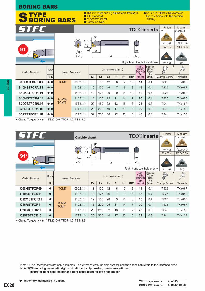
E028
91°øD4
H1
L1
L3
F1
91°60°
øD1
RR° Re
91°øD4
H1
L1
L3
F1
91°60°
øD1
RR° Re
STFC
Right hand tool holder shown.
STFC
Right hand tool holder only.
Order Number Stock
Insert Number Dimensions (mm)
Min.Cutting
Diameter D1
(mm)
StandardCornerRadius Re
(mm)
*
R L D4 L1 L3 F1 H1 RR° Clamp Screw Wrench
S08FSTFCR/L09 a a TCMT 0902pp 8 80 12 6 7 15 11 0.4 TS22 TKY06F
S10HSTFCR/L11 a a
TCMWTCMT
1102pp 10 100 16 7 9 13 13 0.4 TS25 TKY08F
S12KSTFCR/L11 a a 1102pp 12 125 20 9 11 10 16 0.4 TS25 TKY08F
S16MSTFCR/L11 a a 1102pp 16 150 25 11 14 7 20 0.4 TS25 TKY08F
S20QSTFCR/L16 a a 16T3pp 20 180 32 13 18 7 25 0.8 TS4 TKY15F
S25RSTFCR/L16 a a 16T3pp 25 200 40 17 23 5 32 0.8 TS4 TKY15F
S32SSTFCR/L16 a a 16T3pp 32 250 50 22 30 5 40 0.8 TS4 TKY15F
Order Number Stock
Insert Number Dimensions (mm)
Min.Cutting
Diameter D1
(mm)
StandardCornerRadius Re
(mm)
*
R D4 L1 L3 F1 H1 RR° Clamp Screw Wrench
C08HSTFCR09 a TCMT 0902pp 8 100 12 6 7 15 11 0.4 TS22 TKY06F
C10KSTFCR11 a
TCMWTCMT
1102pp 10 125 16 7 9 13 13 0.4 TS25 TKY08F
C12MSTFCR11 a 1102pp 12 150 20 9 11 10 16 0.4 TS25 TKY08F
C16RSTFCR11 a 1102pp 16 200 25 11 14 7 20 0.4 TS25 TKY08F
C20SSTFCR16 a 16T3pp 20 250 32 13 18 7 25 0.8 TS4 TKY15F
C25TSTFCR16 a 16T3pp 25 300 40 17 23 5 32 0.8 TS4 TKY15F
Finish Medium FV Standard
(11,16) (09,11,16)
Flat Top PCD/CBN
(11,16) (11)
Finish Medium FV Standard
(11,16) (09,11,16)
Flat Top PCD/CBN
(11,16) (11)
TCpp type inserts A103 CBN & PCD inserts B042, B058
BORING BARSB
OR
ING
a The minimum cutting diameter is from &11.a ISO standard.a 7° positive insert.a Screw-on type.
a l/d is 3 to 5 times the diameter (up to 7 times with the carbide shank).
* Clamp Torque (N • m) : TS22=0.6, TS25=1.0, TS4=3.5
* Clamp Torque (N • m) : TS22=0.6, TS25=1.0, TS4=3.5
Carbide shank TCooinserts
TCooinserts
STYPE BORING BARS
a : Inventory maintained in Japan.
(Note 1) The insert photos are only examples. The letters refer to the chip breaker and the dimension refers to the inscribed circle. (Note 2) When using insert with right and left hand chip breaker, please use left hand insert for right hand holder and right hand insert for left hand holder.

E029
93°øD4
H1
L1
L3
F1
F2
50°93°
øD1
RR° Re
93°øD4
H1
L1
L3
øD1
RR°
93°
F1
F2
50°
Re
Order Number Stock
Insert Number Dimensions (mm)
Min.Cutting
Diameter D1
(mm)
StandardCornerRadius Re
(mm)
*
R L D4 L1 L3 F1 F2 H1 RR° Clamp Screw Wrench
S10HSDUCR/L07 a a
DCMTDCETDCGTDCMWDCGW
NP-DCGWNP-DCMT
0702pp 10 100 16 7 2.4 9 13 13 0.4 TS25 TKY08F
S12KSDUCR/L07 a a 0702pp 12 125 20 9 3.4 11 10 16 0.4 TS25 TKY08F
S16MSDUCR/L07 a a 0702pp 16 150 25 11 3.9 14 7 20 0.4 TS25 TKY08F
S20QSDUCR/L11 a a 11T3pp 20 180 32 13 4.4 18 7 25 0.8 TS4 TKY15F
S25RSDUCR/L15 a a 1504pp 25 200 40 17 6.9 23 5 32 0.8 TS5 TKY25F
S32SSDUCR/L15 a a 1504pp 32 250 50 22 8.4 30 5 40 0.8 TS5 TKY25F
S40TSDUCR/L15 a a 1504pp 40 300 63 27 9.4 37 5 50 0.8 TS5 TKY25F
Order Number Stock
Insert Number Dimensions (mm)
Min.Cutting
Diameter D1
(mm)
StandardCornerRadius Re
(mm)
*
R D4 L1 L3 F1 F2 H1 RR° Clamp Screw Wrench
C10KSDUCR07 a DCMTDCETDCGTDCMWDCGW
NP-DCGWNP-DCMT
0702pp 10 125 16 7 2.1 9 13 13 0.4 TS25 TKY08F
C12MSDUCR07 a 0702pp 12 150 20 9 3.1 11 10 16 0.4 TS25 TKY08F
C16RSDUCR07 a 0702pp 16 200 25 11 3.1 14 7 20 0.4 TS25 TKY08F
C20SSDUCR11 a 11T3pp 20 250 32 13 3.1 18 7 25 0.8 TS4 TKY15F
C25TSDUCR15 a 1504pp 25 300 40 17 4.9 23 5 32 0.8 TS5 TKY25FDCMWDCMT
SDUC
Right hand tool holder shown.
SDUC
Right hand tool holder only.
Steel Shank l/d<3 l/d=3─4 (Shank Diameter > 25mm)
Carbide Shank l/d<5 l/d=6─7
Work Material Hardness CuttingMode
Cutting Speed (m/min)
Feed (mm/rev)
Depth of Cut (mm)
Cutting Speed (m/min)
Feed (mm/rev)
Depth of Cut (mm)
P Carbon SteelAlloy Steel 180─350HB
Light Cutting 130 (90─160) 0.1 (0.05─0.15) 0.2 120 (80─150) 0.1 (0.05─0.15) 0.2
Medium Cutting 90 (60─120) 0.25 (0.15─0.35) ─3.0 80 (50─110) 0.15 (0.1─0.2) ─1.5
M Stainless Steel <200HB
Light Cutting 140 (100─180) 0.1 (0.05─0.15) 0.2 140 (100─180) 0.1 (0.05─0.15) 0.2
Medium Cutting 70 (50─90) 0.2 (0.15─0.25) ─2.0 60 (40─80) 0.15 (0.1─0.2) ─1.0
N Aluminium Alloy ─
Light Cutting 300 (200─400) 0.1 (0.05─0.15) 0.2 300 (200─400) 0.1 (0.05─0.15) 0.2
Medium Cutting 200 (150─250) 0.1 (0.05─0.15) ─2.0 200 (150─250) 0.1 (0.05─0.15) ─1.5
DCpp type inserts A093─A096 CBN & PCD inserts B040, B041, B057 SPARE PARTS P001 TECHNICAL DATA Q001
Finish Finish Light Medium FV R/L-F SV MV
(07,11) (07,11) (07,11) (07,11)
Medium Flat Top PCD/CBN Standard
(07,11,15) (07,11,15) (07,11)
Finish Finish Light Medium FV L-F SV MV
(07,11) (07,11) (07,11) (07,11)
Medium Flat Top PCD/CBN Standard
(07,11,15) (07,11,15) (07,11)
BO
RIN
G
* Clamp Torque (N • m) : TS25=1.0, TS4=3.5, TS5=7.5
* Clamp Torque (N • m) : TS25=1.0, TS4=3.5, TS5=7.5
Carbide shank DCooinserts
DCooinserts
RECOMMENDED CUTTING CONDITIONS

E030
95° 95°
L3
F1
øD1
60°
RR°
L1 øD4
H1Re
95°
øD1
RR°
95°
F1
60°
L1
L3
øD4
H1Re
SCLC
Right hand tool holder shown.
Order Number Stock
Insert Number Dimensions (mm)
Min.Cutting
Diameter D1
(mm)
StandardCorner Radius Re
(mm)
*
R L D4 L1 L3 F1 H1 RR° Clamp Screw Wrench
S08FSCLCR/L06 a a
CCMHCCMTCCETCCGTCCMWCCGW
NP-CCGW
0602pp 8 80 12 6 7 15 11 0.4 TS25 TKY08F
S10HSCLCR/L06 a a 0602pp 10 100 16 7 9 13 13 0.4 TS25 TKY08F
S12KSCLCR/L06 a a 0602pp 12 125 20 9 11 10 16 0.4 TS25 TKY08F
S16MSCLCR/L09 a a 09T3pp 16 150 25 11 14 7 20 0.8 TS4 TKY15F
S20QSCLCR/L09 a a 09T3pp 20 180 32 13 18 7 25 0.8 TS4 TKY15F
S25RSCLCR/L12 a a 1204pp 25 200 40 17 23 5 32 0.8 TS5 TKY25F
S32SSCLCR/L12 a a 1204pp 32 250 50 22 30 5 40 0.8 TS5 TKY25F
S40TSCLCR/L12 a a 1204pp 40 300 63 27 37 5 50 0.8 TS5 TKY25F
SCLC
Right hand tool holder only.
Order Number Stock
Insert Number Dimensions (mm)
Min.Cutting
Diameter D1
(mm)
StandardCornerRadius Re
(mm)
*
R D4 L1 L3 F1 H1 RR° Clamp Screw Wrench
C08HSCLCR06 a CCMHCCMTCCETCCGTCCMWCCGW
NP-CCGW
0602pp 8 100 12 6 7 15 11 0.4 TS25 TKY08F
C10KSCLCR06 a 0602pp 10 125 16 7 9 13 13 0.4 TS25 TKY08F
C12MSCLCR06 a 0602pp 12 150 20 9 11 10 16 0.4 TS25 TKY08F
C16RSCLCR09 a 09T3pp 16 200 25 11 14 7 20 0.8 TS4 TKY15F
C20SSCLCR09 a 09T3pp 20 250 32 13 18 7 25 0.8 TS4 TKY15F
CCpp type inserts A088─A091 CBN & PCD inserts B036─B038, B056
Finish Medium FV Standard
(06,09) (06,09,12)
Flat Top PCD/CBN
(06,09,12) (06,09,12)
Finish Medium FV Standard
(06,09) (06,09)
Flat Top PCD/CBN
(06,09) (06,09)
BORING BARSB
OR
ING
* Clamp Torque (N • m) : TS25=1.0, TS4=3.5, TS5=7.5
* Clamp Torque (N • m) : TS25=1.0, TS4=3.5
Carbide shank CCooinserts
CCooinserts
STYPE BORING BARS
a The minimum cutting diameter is from &11.a ISO standard.a 7° positive insert.a Screw-on type.
a l/d is 3 to 5 times the diameter (up to 7 times with the carbide shank).
a : Inventory maintained in Japan.
(Note 1) The insert photos are only examples. The letters refer to the chip breaker and the dimension refers to the inscribed circle. (Note 2) When using insert with right and left hand chip breaker, please use left hand insert for right hand holder and right hand insert for left hand holder.

E031
107°30´
107°30´
L1 øD4
H1L3
F1
F2
øD1
50°
RR°
107°30´
Re
107°30´
L1
L3
F1
F2
øD4øD1
50°
RR° H1Re
Order Number Stock
Insert Number Dimensions (mm)
Min.Cutting
Diameter D1
(mm)
StandardCornerRadius Re
(mm)
*
R L D4 L1 L3 F1 F2 H1 RR° Clamp Screw Wrench
S10HSDQCR/L07 a a
DCMTDCETDCGTDCMWDCGW
NP-DCMWNP-DCMT
0702pp 10 100 16 7 2.4 9 13 13 0.4 TS25 TKY08F
S12KSDQCR/L07 a a 0702pp 12 125 20 9 3.4 11 10 16 0.4 TS25 TKY08F
S16MSDQCR/L07 a a 0702pp 16 150 25 11 3.9 14 7 20 0.4 TS25 TKY08F
S20QSDQCR/L11 a a 11T3pp 20 180 32 13 4.4 18 7 25 0.8 TS4 TKY15F
S25RSDQCR/L15 a a 1504pp 25 200 40 17 6.9 23 5 32 0.8 TS5 TKY25F
S32SSDQCR15 a 1504pp 32 250 50 22 8.4 30 5 40 0.8 TS5 TKY25F
S40TSDQCR15 a 1504pp 40 300 63 27 9.4 37 5 50 0.8 TS5 TKY25F
Order Number Stock
Insert Number Dimensions (mm)
Min.Cutting
Diameter D1
(mm)
StandardCornerRadius Re
(mm)
*
R D4 L1 L3 F1 F2 H1 RR° Clamp Screw Wrench
C10KSDQCR07 a DCMTDCETDCGTDCMWDCGW
NP-DCMWNP-DCMT
0702pp 10 125 16 7 2.1 9 13 13 0.4 TS25 TKY08F
C12MSDQCR07 a 0702pp 12 150 20 9 3.1 11 10 16 0.4 TS25 TKY08F
C16RSDQCR07 a 0702pp 16 200 25 11 3.1 14 7 20 0.4 TS25 TKY08F
C20SSDQCR11 a 11T3pp 20 250 32 13 3.1 18 7 25 0.8 TS4 TKY15F
C25TSDQCR15 a 1504pp 25 300 40 17 4.9 23 5 32 0.8 TS5 TKY25FDCMWDCMT
SDQC
Right hand tool holder shown.
SDQC
Right hand tool holder only.
Steel Shank l/d<3 l/d=3─4 (Shank Diameter > 25mm)
Carbide Shank l/d<5 l/d=6─7
Work Material Hardness CuttingMode
Cutting Speed (m/min)
Feed (mm/rev)
Depth of Cut (mm)
Cutting Speed (m/min)
Feed (mm/rev)
Depth of Cut (mm)
P Carbon SteelAlloy Steel 180─350HB
Light Cutting 130 (90─160) 0.1 (0.05─0.15) 0.2 120 (80─150) 0.1 (0.05─0.15) 0.2
Medium Cutting 90 (60─120) 0.25 (0.15─0.35) ─3.0 80 (50─110) 0.15 (0.1─0.2) ─1.5
M Stainless Steel <200HB
Light Cutting 140 (100─180) 0.1 (0.05─0.15) 0.2 140 (100─180) 0.1 (0.05─0.15) 0.2
Medium Cutting 70 (50─90) 0.2 (0.15─0.25) ─2.0 60 (40─80) 0.15 (0.1─0.2) ─1.0
N Aluminium Alloy ─
Light Cutting 300 (200─400) 0.1 (0.05─0.15) 0.2 300 (200─400) 0.1 (0.05─0.15) 0.2
Medium Cutting 200 (150─250) 0.1 (0.05─0.15) ─2.0 200 (150─250) 0.1 (0.05─0.15) ─1.5
DCpp type inserts A093─A096 CBN & PCD inserts B040, B041, B057 SPARE PARTS P001 TECHNICAL DATA Q001
Finish Finish Light Medium FV R/L-F SV MV
(07,11) (07,11) (07,11) (07,11)
Medium Flat Top PCD/CBN Standard
(07,11,15) (07,11,15) (07,11)
Finish Finish Light Medium FV L-F SV MV
(07,11) (07,11) (07,11) (07,11)
Medium Flat Top PCD/CBN Standard
(07,11,15) (07,11,15) (07,11)
BO
RIN
G
* Clamp Torque (N • m) : TS25=1.0, TS4=3.5, TS5=7.5
* Clamp Torque (N • m) : TS25=1.0, TS4=3.5, TS5=7.5
Carbide shank DCooinserts
DCooinserts
RECOMMENDED CUTTING CONDITIONS
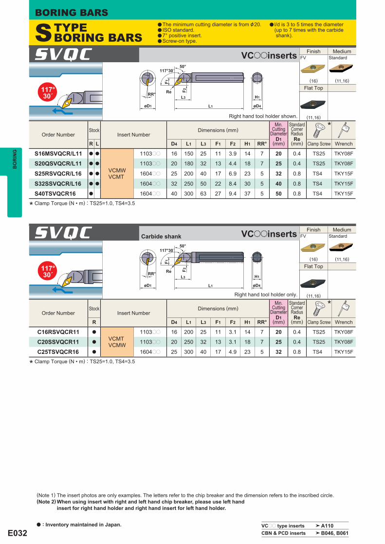
E032
117°30´
117°30´
117°30´
øD4
H1
L1
L3
øD1
RR°
50°
F1
F2Re
L1
L3
øD4øD1
RR° H1
F1
F2
50°117°30´
Re
SVQC
Right hand tool holder shown.
SVQC
Right hand tool holder only.
Order Number Stock
Insert Number Dimensions (mm)
Min.Cutting
Diameter D1
(mm)
StandardCornerRadius Re
(mm)
*
R L D4 L1 L3 F1 F2 H1 RR° Clamp Screw Wrench
S16MSVQCR/L11 a a
VCMWVCMT
1103pp 16 150 25 11 3.9 14 7 20 0.4 TS25 TKY08F
S20QSVQCR/L11 a a 1103pp 20 180 32 13 4.4 18 7 25 0.4 TS25 TKY08F
S25RSVQCR/L16 a a 1604pp 25 200 40 17 6.9 23 5 32 0.8 TS4 TKY15F
S32SSVQCR/L16 a a 1604pp 32 250 50 22 8.4 30 5 40 0.8 TS4 TKY15F
S40TSVQCR16 a 1604pp 40 300 63 27 9.4 37 5 50 0.8 TS4 TKY15F
Order Number Stock
Insert Number Dimensions (mm)
Min.Cutting
Diameter D1
(mm)
StandardCornerRadius Re
(mm)
*
R D4 L1 L3 F1 F2 H1 RR° Clamp Screw Wrench
C16RSVQCR11 a
VCMTVCMW
1103pp 16 200 25 11 3.1 14 7 20 0.4 TS25 TKY08F
C20SSVQCR11 a 1103pp 20 250 32 13 3.1 18 7 25 0.4 TS25 TKY08F
C25TSVQCR16 a 1604pp 25 300 40 17 4.9 23 5 32 0.8 TS4 TKY15F
VCpp type inserts A110 CBN & PCD inserts B046, B061
Finish Medium FV Standard
(16) (11,16)
Flat Top
(11,16)
Finish Medium FV Standard
(16) (11,16)
Flat Top
(11,16)
BORING BARSB
OR
ING
* Clamp Torque (N • m) : TS25=1.0, TS4=3.5
* Clamp Torque (N • m) : TS25=1.0, TS4=3.5
Carbide shank VCooinserts
VCooinserts
STYPE BORING BARS
a The minimum cutting diameter is from &20.a ISO standard.a 7° positive insert.a Screw-on type.
a l/d is 3 to 5 times the diameter (up to 7 times with the carbide shank).
a : Inventory maintained in Japan.
(Note 1) The insert photos are only examples. The letters refer to the chip breaker and the dimension refers to the inscribed circle. (Note 2) When using insert with right and left hand chip breaker, please use left hand insert for right hand holder and right hand insert for left hand holder.

E033
75°
93°
øD1
RR°
75°
F1
60°
L1
L3
øD4
H1Re
øD1
RR°
L1
L3
F1
F2
50°
93°
øD4
H1Re
SSKC
Right hand tool holder shown.
SVUC
Right hand tool holder only.
Order Number Stock
Insert Number Dimensions (mm)
Min.Cutting
Diameter D1
(mm)
StandardCornerRadius Re
(mm)
*
R L D4 L1 L3 F1 H1 RR° Clamp Screw Wrench
S16MSSKCR/L09 a a
SCMWSCMT
09T3pp 16 150 25 11 14 7 20 0.8 TS4 TKY15F
S20QSSKCR/L09 a a 09T3pp 20 180 32 13 18 7 25 0.8 TS4 TKY15F
S25RSSKCR/L12 a a 1204pp 25 200 40 17 23 5 32 0.8 TS5 TKY25F
Order Number Stock
Insert Number Dimensions (mm)
Min.Cutting
Diameter D1
(mm)
StandardCornerRadius Re
(mm)
*
R L D4 L1 L3 F1 F2 H1 RR° Clamp Screw Wrench
S20QSVUCR/L11 a a
VCMWVCMT
1103pp 20 180 32 13 4.4 18 7 25 0.4 TS25 TKY08F
S25RSVUCR/L16 a a 1604pp 25 200 40 17 6.9 23 5 32 0.8 TS4 TKY15F
S32SSVUCR/L16 a a 1604pp 32 250 50 22 8.4 30 5 40 0.8 TS4 TKY15F
S40TSVUCR/L16 a a 1604pp 40 300 63 27 9.4 37 5 50 0.8 TS4 TKY15F
Steel Shank l/d<3 l/d=3─4 (Shank Diameter > 25mm)
Carbide Shank l/d<5 l/d=6─7
Work Material Hardness CuttingMode
Cutting Speed (m/min)
Feed (mm/rev)
Depth of Cut (mm)
Cutting Speed (m/min)
Feed (mm/rev)
Depth of Cut (mm)
P Carbon SteelAlloy Steel 180─350HB
Light Cutting 130 (90─160) 0.1 (0.05─0.15) 0.2 120 (80─150) 0.1 (0.05─0.15) 0.2
Medium Cutting 90 (60─120) 0.25 (0.15─0.35) ─3.0 80 (50─110) 0.15 (0.1─0.2) ─1.5
M Stainless Steel <200HB
Light Cutting 140 (100─180) 0.1 (0.05─0.15) 0.2 140 (100─180) 0.1 (0.05─0.15) 0.2
Medium Cutting 70 (50─90) 0.2 (0.15─0.25) ─2.0 60 (40─80) 0.15 (0.1─0.2) ─1.0
N Aluminium Alloy ─
Light Cutting 300 (200─400) 0.1 (0.05─0.15) 0.2 300 (200─400) 0.1 (0.05─0.15) 0.2
Medium Cutting 200 (150─250) 0.1 (0.05─0.15) ─2.0 200 (150─250) 0.1 (0.05─0.15) ─1.5
SCpp type inserts A101 VCpp type inserts A110 SPARE PARTS P001 CBN & PCD inserts B046, B061 TECHNICAL DATA Q001
Finish Medium FV Standard
(09) (09,12)
Flat Top
(09,12)
Finish Medium FV Standard
(16) (11,16)
Flat Top
(11,16)
BO
RIN
G
* Clamp Torque (N • m) : TS4=3.5, TS5=7.5
* Clamp Torque (N • m) : TS25=1.0, TS4=3.5
SCooinserts
VCooinserts
RECOMMENDED CUTTING CONDITIONS

E034
5°
L1 øD4
H1
L3
L7
F1 95°
F2
øD1
RR° Re
SCZC
Right hand tool holder shown.
Order Number Stock
Insert Number Dimensions (mm)
Min.Cutting
Diameter D1
(mm)
StandardCornerRadius Re
(mm)
*
R L D4 L1 L3 L7 F1 F2 H1 RR° Clamp Screw Wrench
S16MSCZCR/L06 a a 0602pp 16 150 36 11 11 3 14 10 20 0.4 TS25 TKY08F
S20QSCZCR/L09 a a 09T3pp 20 180 50 18 13 3 18 7 25 0.8 TS4 TKY15F
CCMHCCMTCCETCCGTCCMW
Work Material Hardness CuttingMode
l/d<3 l/d=3─4 (Shank Diameter > 25mm) Cutting Speed
(m/min) Feed
(mm/rev) Depth of Cut
(mm) Cutting Speed
(m/min) Feed
(mm/rev) Depth of Cut
(mm)
P Carbon SteelAlloy Steel 180─350HB
Light Cutting 130 (90─160) 0.1 (0.05─0.15) 0.2 120 (80─150) 0.1 (0.05─0.15) 0.2
Medium Cutting 90 (60─120) 0.25 (0.15─0.35) ─3.0 80 (50─110) 0.15 (0.1─0.2) ─1.5
M Stainless Steel <200HB
Light Cutting 140 (100─180) 0.1 (0.05─0.15) 0.2 140 (100─180) 0.1 (0.05─0.15) 0.2
Medium Cutting 70 (50─90) 0.2 (0.15─0.25) ─2.0 60 (40─80) 0.15 (0.1─0.2) ─1.0
N Aluminium Alloy ─
Light Cutting 300 (200─400) 0.1 (0.05─0.15) 0.2 300 (200─400) 0.1 (0.05─0.15) 0.2
Medium Cutting 200 (150─250) 0.1 (0.05─0.15) ─2.0 200 (150─250) 0.1 (0.05─0.15) ─1.5
CCpp type inserts A088─A091 CBN & PCD inserts B036─B038, B056
Finish Medium FV Standard
(06,09) (06,09)
Flat Top PCD/CBN
(06,09) (06,09)
BORING BARSB
OR
ING
(Note 1) The insert photos are only examples. The letters refer to the chip breaker and the dimension refers to the inscribed circle. (Note 2) When using insert with right and left hand chip breaker, please use right hand insert for right hand holder and left hand insert for left hand holder.
* Clamp Torque (N • m) : TS25=1.0, TS4=3.5
CCooinserts
RECOMMENDED CUTTING CONDITIONS
STYPE BORING BARS
a The minimum cutting diameter is from &20.a ISO standard.a 7° positive insert.a Screw-on type.
a l/d is 3 to 5 times the diameter (up to 7 times with the carbide shank).
a : Inventory maintained in Japan.

E035
75°
91°
øD4
H1
L1
L3
F1
75°
6°
RR°
øD1
Re
øD4
H1
L1
L3RR°
6°
F1
91°øD1
Re
PSKN
Right hand tool holder shown.
PTFN
Right hand tool holder shown.
Order Number Stock
Insert Number Dimensions (mm)
Min.
Cuttin
gDi
amete
r
D1
Standa
rdCo
rner R
adius
Re
*2 *2
R L D4 L1 L3 F1 H1 RR° Shim Shim Pin
ClampLever
ClampScrew Wrench Plug Clamp
Pin Pin Screw (mm) (mm)
A20QPSKNR/L09 a a SNMASNMGSNMMSNGASNGG
0903pp 20 180 32 13 18 13 25 0.8 ─ ─ ─ ─ HKY15RHKY25R
HGM-PT1/8 HP3T P208AM HSS03005
A25RPSKNR/L12 a a 1204pp 25 200 40 17 23 13 32 0.8 MLSP42 ─ ─ ─ HKY15RHKY30R
HGM-PT1/4 HP43 P210AM HSS03005
A32SPSKNR/L12 a a 1204pp 32 250 50 22 30 13 44 0.8 LLSSN42 LLP14 LLCL14 LLCS108S HKY30R HGM-PT3/8 ─ ─ ─
A40TPSKNR12 a 1204pp 40 300 63 27 37 10 54 0.8 LLSSN42 LLP14 LLCL14 LLCS108S HKY30R HGM-PT3/8 ─ ─ ─
Order Number Stock
Insert Number Dimensions (mm)
Min.
Cuttin
gDi
amete
r
D1
Standa
rdCo
rner R
adius
Re
*2 *2
R L D4 L1 L3 F1 H1 RR° Shim Shim Pin
ClampLever
ClampScrew Wrench Plug Clamp
Pin Pin Screw (mm) (mm)
A20QPTFNR/L16 a a
TNMATNMGTNMMTNGATNGG
1604pp 20 180 32 13 18 15 25 0.8 ─ ─ ─ ─ HKY15RHKY25R
HGM-PT1/8 HP31 P208AM HSS03005
A25RPTFNR/L16 a a 1604pp 25 200 40 17 23 13 32 0.8 MLTP32 ─ ─ ─ HKY15RHKY25R
HGM-PT1/4 HP33 P208AM HSS03005
A32SPTFNR/L16 a a 1604pp 32 250 50 22 30 13 44 0.8 LLSTN32 LLP13 LLCL13 LLCS106 HKY25R HGM-PT3/8 ─ ─ ─
A40TPTFNR/L22 a a 2204pp 40 300 63 27 37 10 54 0.8 LLSTN42 LLP14 LLCL14 LLCS108S HKY30R HGM-PT3/8 ─ ─ ─
A50UPTFNR/L22 a a 2204pp 50 350 80 35 47 9 70 0.8 LLSTN42 LLP14 LLCL14 LLCS108S HKY30R HGM-PT3/8 ─ ─ ─
Work Material Hardness CuttingMode
l/d<3 l/d=3─4
Cutting Speed (m/min)
Feed (mm/rev)
Depth of Cut (mm)
Cutting Speed (m/min)
Feed (mm/rev)
Depth of Cut (mm)
P Carbon SteelAlloy Steel 180─350HB Medium Cutting 110 (80─140) 0.25 (0.1─0.4) ─5.0 110 (80─140) 0.2 (0.1─0.3) ─4.0
M Stainless Steel <200HB Medium Cutting 80 (60─100) 0.2 (0.1─0.3) ─4.0 70 (50─100) 0.15 (0.1─0.25) ─3.0
K Gray Cast Iron Tensile Strength <350MPa Medium Cutting 80 (60─100) 0.25 (0.1─0.4) ─5.0 80 (60─100) 0.2 (0.1─0.3) ─4.0
*1
*1
*1
*1
SNpp type inserts A069─A073 TNpp type inserts A074─A079 SPARE PARTS P001 CBN & PCD inserts B027─B029, B053 TECHNICAL DATA Q001
Finish Light Medium Medium FH SH MP MH
(09,12) (12) (12) (12)
Medium Stainless G Class CBN Standard MS R/L
(09,12) (09,12) (09,12) (12)
Finish Light Medium Medium FH SH MP MH
(16) (16,22) (16,22) (16,22)
Medium Stainless G Class CBN Standard MS R/L
(16,22) (16,22) (16,22) (16)
BO
RIN
G
*2 Clamp Torque (N • m) : LLCS108S=3.3, HP3T=2.2, HP43=3.3
*2 Clamp Torque (N • m) : LLCS106=2.2, LLCS108S=3.3, HP31=2.2, HP33=2.2
With coolant hole SNooinserts
With coolant hole TNooinserts
RECOMMENDED CUTTING CONDITIONS
PTYPE BORING BARS
a The minimum cutting diameter is from &25.a ISO standard.a Economical negative insert.a Lever lock type.
a l/d is 3 times the diameter.
(Note 1) The insert photos are only examples. The letters refer to the chip breaker and the dimension refers to the inscribed circle. (Note 2) When using insert with right and left hand chip breaker, please use left hand insert for right hand holder and right hand insert for left hand holder.
*1 Pin Lock Type
*1 Pin Lock Type

E036
93°
95°
RR°
6°
øD1
F1
F2
93°
L1L3
øD4
H1Re
øD4H1
L1
L3
F1
95°
RR°
6°
øD1
Re
PDUN
Right hand tool holder shown.
PCLN
Right hand tool holder shown.
Order Number Stock
Insert Number Dimensions (mm)
Min.
Cuttin
gDi
amete
r
D1
Standa
rdCo
rner R
adius
Re
*2 *2
R L D4 L1 L3 F1 F2 H1 RR° Shim Shim Pin
ClampLever
ClampScrew Wrench Plug Clamp
Pin Pin Screw (mm) (mm)
A20QPDUNR/L11 a a
DNMADNMGDNMXDNMMDNGADNGG
1104pp 20 180 32 15 6.4 18 13 26 0.8 ─ ─ LLCL23S LLCS125 HKY20R HGM-PT1/8 ─ ─ ─
A25RPDUNR/L11 a a 1104pp 25 200 40 17 6.9 23 15 32 0.8 LLSDN32 LLP13 LLCL23 LLCS106 HKY25R HGM-PT1/4 ─ ─ ─
A25RPDUNR/L15 a a 1504pp 25 200 40 17 6.9 23 13 32 0.8 MLDP42 ─ ─ ─ HKY15RHKY30R
HGM-PT1/4 HP43 P210AM HSS03005
A32SPDUNR/L11 a a 1104pp 32 250 50 22 8.4 30 13 44 0.8 LLSDN32 LLP13 LLCL23 LLCS106 HKY25R HGM-PT3/8 ─ ─ ─
A32SPDUNR/L15 a a 1504pp 32 250 50 22 8.4 30 13 44 0.8 LLSDN42 LLP14 LLCL24 LLCS108S HKY30R HGM-PT3/8 ─ ─ ─
A40TPDUNR/L15 a a 1504pp 40 300 63 27 9.4 37 10 54 0.8 LLSDN42 LLP14 LLCL24 LLCS108S HKY30R HGM-PT3/8 ─ ─ ─
A50UPDUNR/L15 a a 1504pp 50 350 80 35 12.4 47 9 70 0.8 LLSDN42 LLP14 LLCL24 LLCS108S HKY30R HGM-PT3/8 ─ ─ ─
Order Number Stock
Insert Number Dimensions (mm)
Min.
Cuttin
gDi
amete
r
D1
Standa
rdCo
rner R
adius
Re
*2 *2
R L D4 L1 L3 F1 H1 RR° Shim Shim Pin
ClampLever
ClampScrew Wrench Plug Clamp
Pin Pin Screw (mm) (mm)
A16MPCLNR/L09 a a
CNMACNMGCNMMCNGG
09T3pp 16 150 25 11 14 15 20 0.8 ─ ─ LLCL13S LLCS105 HKY20R HGM-PT1/8 ─ ─ ─
A20QPCLNR/L09 a a 09T3pp 20 180 32 13 18 13 25 0.8 ─ ─ ─ ─ HKY25RHKY15R
HGM-PT1/8 HP3T P208AM HSS03005
A20QPCLNR/L09N a a 09T3pp 20 180 32 13 18 13 25 0.8 ─ ─ LLCL13S LLCS105 HKY20R HGM-PT1/8 ─ ─ ─
A25RPCLNR/L09 a a 09T3pp 25 200 40 17 23 13 32 0.8 ─ ─ LLCL13S LLCS105 HKY20R HGM-PT1/4 ─ ─ ─
A25RPCLNR/L12 a a 1204pp 25 200 40 17 23 13 32 0.8 MLCP42 ─ ─ ─ HKY30RHKY15R
HGM-PT1/4 HP43 P210AM HSS03005
A32SPCLNR/L09 a a 09T3pp 32 250 50 22 30 13 44 0.8 LLSCN3T3 LLP13 LLCL13 LLCS106 HKY25R HGM-PT3/8 ─ ─ ─
A32SPCLNR/L12 a a 1204pp 32 250 50 22 30 13 44 0.8 LLSCN42 LLP14 LLCL14 LLCS108S HKY30R HGM-PT3/8 ─ ─ ─
A40TPCLNR/L12 a a 1204pp 40 300 63 27 37 10 54 0.8 LLSCN42 LLP14 LLCL14 LLCS108S HKY30R HGM-PT3/8 ─ ─ ─
A50UPCLNR12 a 1204pp 50 350 80 35 47 10 63 0.8 LLSCP42 LLP14 LLCL14 LLCS108S HKY30R HGM-PT3/8 ─ ─ ─
*1
*1
*1
DNpp type inserts A063─A067 CNpp type inserts A058─A062 CBN & PCD inserts B022─B026, B052
Finish Light Medium Medium FH SH MP MH
(15) (11,15) (15) (15)
Medium Stainless G Class CBN Standard MS R/L
(11,15) (11,15) (15) (15)
Finish Light Light Medium FH SA SH MP
(12) (12) (09,12) (12)
Medium Medium Stainless CBNMH Standard MS
(12) (09,12) (09,12) (12)
BORING BARSB
OR
ING
*2 Clamp Torque (N • m) : LLCS125=1.5, LLCS106=2.2, LLCS108S=3.3, HP43=3.3
*2 Clamp Torque (N • m) : LLCS105=1.5, LLCS106=2.2, LLCS108S=3.3, HP3T=2.2, HP43=3.3
With coolant hole DNooinserts
With coolant hole CNooinserts
*1 Pin Lock Type
*1 Pin Lock Type
PTYPE BORING BARS
a The minimum cutting diameter is from &20.a ISO standard.a Economical negative insert.a Lever lock type.
a l/d is 3 times the diameter.
a : Inventory maintained in Japan.
(Note 1) The insert photos are only examples. The letters refer to the chip breaker and the dimension refers to the inscribed circle. (Note 2) When using insert with right and left hand chip breaker, please use left hand insert for right hand holder and right hand insert for left hand holder.
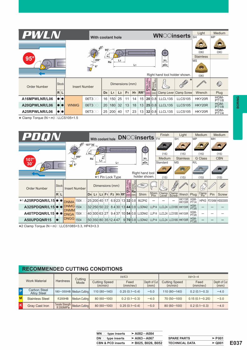
E037
95°
107°30´
øD4
H1
L1
L3
F1
95°øD1
RR°
6°Re
øD4
H1
øD1
RR°
6°L1
L3
F1
F2
107°30´
Re
PDQN
Right hand tool holder shown.
Order Number Stock
Insert Number Dimensions (mm)
Min.
Cuttin
gDi
amete
r
D1
Standa
rdCo
rner R
adius
Re
*
R L D4 L1 L3 F1 H1 RR° Clamp Lever Clamp Screw Wrench Plug (mm) (mm)
A16MPWLNR/L06 a a
WNMG
06T3pp 16 150 25 11 14 15 20 0.8 LLCL13S LLCS105 HKY20R HGM-PT1/8
A20QPWLNR/L06 a a 06T3pp 20 180 32 13 18 13 25 0.8 LLCL13S LLCS105 HKY20R HGM-PT1/8
A25RPWLNR/L06 a a 06T3pp 25 200 40 17 23 13 32 0.8 LLCL13S LLCS105 HKY20R HGM-PT1/4
Order Number Stock
Insert Number Dimensions (mm)
Min.
Cuttin
gDi
amete
r
D1
Standa
rdCo
rner R
adius
Re
*2 *2
R L D4 L1 L3 F1 F2 H1 RR° Shim ShimPin
ClampLever
ClampScrew Wrench Plug Clamp
Pin Pin Screw (mm) (mm)
A25RPDQNR/L15 a a DNMADNMGDNMMDNGADNGG
1504pp 25 200 40 17 6.9 23 13 32 0.8 MLDP42 ─ ─ ─ HKY15RHKY30R
HGM-PT1/4 HP43 P210AM HSS03005
A32SPDQNR/L15 a a 1504pp 32 250 50 22 8.4 30 13 44 0.8 LLSDN42 LLP14 LLCL24 LLCS108S HKY30R HGM-PT3/8 ─ ─ ─
A40TPDQNR/L15 a a 1504pp 40 300 63 27 9.4 37 10 54 0.8 LLSDN42 LLP14 LLCL24 LLCS108S HKY30R HGM-PT3/8 ─ ─ ─
A50UPDQNR15 a 1504pp 50 350 80 35 12.4 47 9 70 0.8 LLSDN42 LLP14 LLCL24 LLCS108S HKY30R HGM-PT3/8 ─ ─ ─
PWLN
Right hand tool holder shown.
Work Material Hardness CuttingMode
l/d<3 l/d=3─4
Cutting Speed (m/min)
Feed (mm/rev)
Depth of Cut (mm)
Cutting Speed (m/min)
Feed (mm/rev)
Depth of Cut (mm)
P Carbon SteelAlloy Steel 180─350HB Medium Cutting 110 (80─140) 0.25 (0.1─0.4) ─5.0 110 (80─140) 0.2 (0.1─0.3) ─4.0
M Stainless Steel <200HB Medium Cutting 80 (60─100) 0.2 (0.1─0.3) ─4.0 70 (50─100) 0.15 (0.1─0.25) ─3.0
K Gray Cast Iron Tensile Strength <350MPa Medium Cutting 80 (60─100) 0.25 (0.1─0.4) ─5.0 80 (60─100) 0.2 (0.1─0.3) ─4.0
*1
WNpp type inserts A082─A084 DNpp type inserts A063─A067 SPARE PARTS P001 CBN & PCD inserts B025, B026, B052 TECHNICAL DATA Q001
Finish Light Medium Medium FH SH MP MH
(15) (15) (15) (15)
Medium Stainless G Class CBN Standard MS R/L
(15) (15) (15) (15)
Light Medium SH MP
(06) (06)
Stainless MS
(06)
BO
RIN
G
* Clamp Torque (N • m) : LLCS105=1.5
*2 Clamp Torque (N • m) : LLCS108S=3.3, HP43=3.3
With coolant hole WNooinserts
With coolant hole DNooinserts
RECOMMENDED CUTTING CONDITIONS
*1 Pin Lock Type

E038
3°øD4
H1
L1L325
F2
93°F1
øD1
RR° Re
PDZN
Right hand tool holder shown.
Order Number Stock Insert
Number Dimensions (mm)
Min.
Cuttin
gDi
amete
r
D1
Standa
rdCo
rner R
adius
Re
*2 *2
R L D4 L1 L3 F1 F2 H1 RR° Shim ShimPin
ClampLever
ClampScrew Wrench Plug Clamp
Pin Pin Screw (mm) (mm)
A25RPDZNR/L15 a a DNMADNMGDNMXDNMMDNGADNGG
1504pp 25 200 65 17 6.7 23 13 32 0.8 MLDP42 ─ ─ ─ HKY15RHKY30R
HGM-PT1/4 HP43 P210AM HSS03005
A32SPDZNR/L15 a a 1504pp 32 250 75 22 8.2 30 13 40 0.8 LLSDN42 LLP14 LLCL24 LLCS108S HKY30R HGM-PT3/8 ─ ─ ─
A40TPDZNR/L15 a a 1504pp 40 300 88 27 9.2 37 10 50 0.8 LLSDN42 LLP14 LLCL24 LLCS108S HKY30R HGM-PT3/8 ─ ─ ─
A50UPDZNR/L15 a a 1504pp 50 350 105 35 12.2 47 9 63 0.8 LLSDN42 LLP14 LLCL24 LLCS108S HKY30R HGM-PT3/8 ─ ─ ─
Work Material Hardness CuttingMode
l/d<3 l/d=3─4
Cutting Speed (m/min)
Feed (mm/rev)
Depth of Cut (mm)
Cutting Speed (m/min)
Feed (mm/rev)
Depth of Cut (mm)
P Carbon SteelAlloy Steel 180─350HB Medium Cutting 110 (80─140) 0.25 (0.1─0.4) ─5.0 110 (80─140) 0.2 (0.1─0.3) ─4.0
M Stainless Steel <200HB Medium Cutting 80 (60─100) 0.2 (0.1─0.3) ─4.0 70 (50─100) 0.15 (0.1─0.25) ─3.0
K Gray Cast Iron Tensile Strength <350MPa Medium Cutting 80 (60─100) 0.25 (0.1─0.4) ─5.0 80 (60─100) 0.2 (0.1─0.3) ─4.0
*1
DNpp type inserts A063─A067 CBN & PCD inserts B025, B026, B052
Finish Light Medium Medium FH SH MP MH
(15) (15) (15) (15)
Medium Stainless G Class CBN Standard MS R/L
(15) (15) (15) (15)
BORING BARSB
OR
ING
With coolant hole DNooinserts
RECOMMENDED CUTTING CONDITIONS
a The minimum cutting diameter is from &32.a ISO standard.a Economical negative insert.a Lever lock type.
a l/d is 3 times the diameter.PTYPE BORING BARS
a : Inventory maintained in Japan.
(Note 1) The insert photos are only examples. The letters refer to the chip breaker and the dimension refers to the inscribed circle. (Note 2) When using insert with right and left hand chip breaker, please use right hand insert for right hand holder and left hand insert for left hand holder.
*2 Clamp Torque (N • m) : LLCS108S=3.3, HP43=3.3
*1 Pin Lock Type

E039
95°øD4
H1
L1
L3
F1
95°øD1
RR°Re
Order Number Stock
Insert Number Dimensions (mm)
Min.
Cuttin
gDi
amete
r
D1
Standa
rdCo
rner R
adius
Re
*
R L D4 L1 L3 F1 H1 RR° Shim ShimPin
ClampBridge
Side LockPlate Spring Clamp
Screw Wrench Plug (mm) (mm)
A25RMWLNR/L08 a a
WNMAWNMG
0804pp 25 200 40 17 23 13 32 0.8 ─ ─ CCK13 CPT24 MES2 SLCS105 HKY25RHKY40R
HGM-PT1/4
A32SMWLNR/L08 a a 0804pp 32 250 50 22 30 13 40 0.8 WPSWC43 CCP44 CCK13 CPT24 MES2 SLCS105 HKY25R
HKY40RHGM-PT3/8
A40TMWLNR/L08 a a 0804pp 40 300 63 27 37 10 50 0.8 WPSWC43 CCP44 CCK13 CPT24 MES2 SLCS105 HKY25R
HKY40RHGM-PT3/8
A50UMWLNR08 a 0804pp 50 350 80 35 63 9 63 0.8 WPSWC43 CCP44 CCK13 CPT24 MES2 SLCS105 HKY25R
HKY40RHGM-PT3/8
Work Material Hardness CuttingMode
l/d<3 l/d=3─4
Cutting Speed (m/min)
Feed (mm/rev)
Depth of Cut (mm)
Cutting Speed (m/min)
Feed (mm/rev)
Depth of Cut (mm)
P Carbon SteelAlloy Steel 180─350HB Medium Cutting 110 (80─140) 0.25 (0.1─0.4) ─5.0 110 (80─140) 0.2 (0.1─0.3) ─4.0
M Stainless Steel <200HB Medium Cutting 80 (60─100) 0.2 (0.1─0.3) ─4.0 70 (50─100) 0.15 (0.1─0.25) ─3.0
K Gray Cast Iron Tensile Strength <350MPa Medium Cutting 80 (60─100) 0.25 (0.1─0.4) ─5.0 80 (60─100) 0.2 (0.1─0.3) ─4.0
MWLN
Right hand tool holder shown.
WNpp type inserts A082─A084 CBN inserts B031 SPARE PARTS P001 TECHNICAL DATA Q001
Finish Light Medium FH SH MP
(08) (08) (08)
Medium Medium Stainless MH Standard MS
(08) (08) (08)
BO
RIN
G
a The minimum cutting is from &32.a Negative trigon shape insert.a Double clamp type.a l/d is 3 times the diameter.
(Note) The insert photos are only examples. The letters refer to the chip breaker and the dimension refers to the inscribed circle.
* Clamp Torque (N • m) : SLCS105=7.0
With coolant hole WNooinserts
RECOMMENDED CUTTING CONDITIONS
MTYPE BORING BARS

E040
91°øD4
H1
L1L2 10
7°3°
øD1 1°
F1
Re
STFE
Right hand tool holder shown.
Order Number Stock
Insert Number Dimensions (mm)
Min.Cutting
Diameter D1
(mm)
StandardCornerRadius Re
(mm)
*
R L D4 L1 L2 F1 H1 Clamp Screw Wrench
S16RSTFER/L16 a a
TEGX...R/L
1603pp 16 200 30 11 14.6 20 0.4 FC400890T TKY10F
S20RSTFER/L16 a a 1603pp 20 200 37 13 18 25 0.4 FC400890T TKY10F
S25SSTFER/L16 a a 1603pp 25 250 40 17 23 32 0.4 FC400890T TKY10F
Work Material Grade Cutting Speed (m/min)
l/d=3 l/d=4 l/d=5 l/d=6
Feed (mm/rev)
Depth of Cut (mm)
Feed (mm/rev)
Depth of Cut (mm)
Feed (mm/rev)
Depth of Cut (mm)
Feed (mm/rev)
Depth of Cut (mm)
N Aluminium Alloy
HTi10 400(200─600)
0.15(0.05─0.25) ─3.0 0.15
(0.05─0.25) ─3.0 0.1(0.05─0.2) ─2.5 0.1
(0.05─0.2) ─1.0
MD220 800(200─1500)
0.15(0.05─0.25) ─3.0 0.15
(0.05─0.25) ─3.0 0.1(0.05─0.2) ─2.5 0.1
(0.05─0.2) ─1.0
TEpp type inserts A104 PCD inserts B063
Medium PCDR/L R/L
(16) (16)
PCD
(16)
BORING BARSB
OR
ING
a Suitable for non-ferrous metal.a 20° positive insert.a Screw-on type.a l/d is 6 times the diameter.
a Excellent vibration resistance.a The minimum cutting diameter is from &20.
* Clamp Torque (N • m) : FC400890T=2.5
TEooinserts
RECOMMENDED CUTTING CONDITIONS
ALTYPE BORING BARS
a : Inventory maintained in Japan.
(Note 1) The insert photos are only examples. The letters refer to the chip breaker and the dimension refers to the inscribed circle. (Note 2) When using insert with right and left hand chip breaker, please use left hand insert for right hand holder and right hand insert for left hand holder.

E041
90° øD4
RR° 6°
øD1
L1
F1
0°
Re
øD4
RR° 6°
øD1
F1
L1
3°
Re
93°
DPTF
Right hand tool holder only.
DPDU
Right hand tool holder only.
Order Number Stock
Insert Number Dimensions (mm)
Min.
Cuttin
gDi
amete
r
D1
Standa
rdCo
rner R
adius
Re
*
R D4 L1 F1 RR° Shim Shim Pin ClampLever
ClampScrew Wrench (mm) (mm)
DPTF132R a 1604pp 32 40 20 12 40 0.8 LLSTN32 LLP13 LLCL13 LLCS106 HKY25R
140R a 2204pp 40 50 25 10 50 0.8 LLSTN42 LLP14 LLCL14 LLCS108 HKY30R
TNMATNMGTNMMTNGATNGG
Order Number Stock
Insert Number Dimensions (mm)
Min.
Cuttin
gDi
amete
r
D1
Standa
rdCo
rner R
adius
Re
*
R D4 L1 F1 RR° Shim Shim Pin ClampLever
ClampScrew Wrench (mm) (mm)
DPDU132R a 1504pp 32 40 25 10 50 0.8 LLSDN42 LLP14 LLCL24 LLCS108 HKY30R
140R a 1504pp 40 50 30 9 60 0.8 LLSDN42 LLP14 LLCL24 LLCS108 HKY30R
DNMADNMGDNMXDNMMDNGADNGG
TNpp type inserts A074─A079 DNpp type inserts A063─A067 SPARE PARTS P001 CBN & PCD inserts B025, B026, B028, B029, B052, B053 TECHNICAL DATA Q001
Finish Light Medium Medium FH SH MP MH
(16) (16,22) (16,22) (16,22)
Medium Stainless G Class CBN Standard MS L
(16,22) (16,22) (16,22) (16)
Finish Light Medium Medium FH SH MP MH
(15) (15) (15) (15)
Medium Stainless G Class CBN Standard MS L
(15) (15) (15) (15)
BO
RIN
G
* Clamp Torque (N • m) : LLCS106=2.2, LLCS108=3.3
* Clamp Torque (N • m) : LLCS108=3.3
TNooinserts
DNooinserts
DTYPE BORING HEAD
a The minimum cutting diameter is from &40.a Economical negative insert.a Lever lock type.a Exchangeable head type.
Please refer to page E043 for arbor.
Please refer to page E043 for arbor.

E042
95°
107°30´
øD4
5°
RR° 6°
øD1
F1
5°
L1
Re
øD4
RR° 6°
øD1
F1
L1
17°30´
Re
DPCL
Right hand tool holder only.
DPDH
Right hand tool holder only.
Order Number Stock
Insert Number Dimensions (mm)
Min.
Cuttin
gDi
amete
r
D1
Standa
rdCo
rner R
adius
Re
*
R D4 L1 F1 RR° Shim Shim Pin ClampLever
ClampScrew Wrench (mm) (mm)
DPCL132R a 1204pp 32 40 20 12 40 0.8 LLSCN42 LLP14 LLCL14 LLCS108 HKY30R
140R a 1204pp 40 50 25 10 50 0.8 LLSCN42 LLP14 LLCL14 LLCS108 HKY30R
CNMACNMGCNMMCNGG
Order Number Stock
Insert Number Dimensions (mm)
Min.
Cuttin
gDi
amete
r
D1
Standa
rdCo
rner R
adius
Re
*
R D4 L1 F1 RR° Shim Shim Pin ClampLever
ClampScrew Wrench (mm) (mm)
DPDH132R a 1504pp 32 40 25 10 50 0.8 LLSDN42 LLP14 LLCL24 LLCS108 HKY30R
140R a 1504pp 40 50 30 9 60 0.8 LLSDN42 LLP14 LLCL24 LLCS108 HKY30R
DNMADNMGDNMMDNGADNGG
CNpp type inserts A058─A062 DNpp type inserts A063─A067 CBN & PCD inserts B022─B026, B052
Finish Light Light Medium FH SH SA MP
(12) (12) (12) (12)
Medium Medium Stainless CBNMH Standard MS
(12) (12) (12) (12)
Finish Light Medium Medium FH SH MP MH
(15) (15) (15) (15)
Medium Medium G Class CBN Standard MS L
(15) (15) (15) (15)
BORING BARSB
OR
ING
* Clamp Torque (N • m) : LLCS108=3.3
* Clamp Torque (N • m) : LLCS108=3.3
CNooinserts
DNooinserts
DTYPE BORING HEAD
a The minimum cutting diameter is from &40.a Economical negative insert.a Lever lock type.a Exchangeable head type.
a : Inventory maintained in Japan.
(Note 1) The insert photos are only examples. The letters refer to the chip breaker and the dimension refers to the inscribed circle. (Note 2) When using insert with right and left hand chip breaker, please use left hand insert for right hand holder and right hand insert for left hand holder.
Please refer to pageE043 for arbor.
Please refer to pageE043 for arbor.

E043
117°30´
øD4
L1
27°30´
øD1
F1
RR°10°Re
DPVP
Right hand tool holder only.
Order Number Stock
Insert Number Dimensions (mm)
Min.
Cuttin
gDi
amete
r
D1
Standa
rdCo
rner R
adius
Re
*
R D4 L1 F1 RR° Shim Lock Pin Lock Screw Stop Ring Wrench (mm) (mm)
DPVP132R a VNMGVNGAVNGG
1604pp 32 40 25 13 50 0.8 PV322 P11S HSP05008C E03 HKY25R
140R a 1604pp 40 50 30 13 60 0.8 PV322 P11S HSP05008C E03 HKY25R
Finish Light Medium Medium FH SH MP MH
(16) (16) (16) (16)
Stainless G Class PCD CBNMS L L-F
(16) (16) (16) (16)
VNpp type inserts A080, A081 CBN & PCD inserts B030, B054 SPARE PARTS P001 TECHNICAL DATA Q001
BO
RIN
G
øD4
L
1.5L1
H1
1
D4 L1 L32 260 300 32
40360310403240
3240
3240
HKY60RSD32 DPoo132RB13232DPoo140RB14040 HKY60RSD4040 310 37 360
32 260 29 300
LH1L1D4
a
a
z x c vB 32 321STANDARD ARBOR FOR D TYPE BORING HEAD
zGeneral Term for Arbor cArbor Diameter (mm) vHead Diameter (mm)xArbor Length (mm)Symbol Symbol Diameter (D4) Symbol Diameter (D4)
HeadOrder Number
Dimensions (mm)Set Bolt Wrench
Sto
ckOrderNumber
* Clamp Torque (N • m) : HSP05008C=2.5
VNooinserts