
Catalogue Shut-off and regulating valves Electronic...
106
DKRCI.PK.000.V1.02 | 520H11462 | 1 © Danfoss | DCS (mwa) | 2016.09 Electronic controllers and transmitters for Industrial Refrigeration Contents Page Liquid level controller, EKE 347 ..................................................................... 3 Media temperature controller, EKC 361 ........................................................... 23 Interface, EKC 366 ................................................................................ 39 Superheat controller, EKC 315A.................................................................... 49 Temperature controller, EKC 319A ................................................................. 65 Capacity controller, EKC 331....................................................................... 75 Capacity controller, type EKC 331T ................................................................ 85 Temperature sensors, types AKS 11, AKS 12, AKS 21, AK-HS 1000 ................................... 97 Pressure transmitters, types AKS 32, AKS 33, AKS 32R, AKS 2050 .................................. 101 Catalogue
Transcript of Catalogue Shut-off and regulating valves Electronic...
Shut-off and regulating valves for Industrial Refrigeration
DKRCI.PK.000.V1.02 | 520H11462 | 1© Danfoss | DCS (mwa) | 2016.09
Electronic controllers and transmitters for Industrial Refrigeration
Contents PageLiquid level controller, EKE 347 . . . . . . . . . . . . . . . . . . . . . . . . . . . . . . . . . . . . . . . . . . . . . . . . . . . . . . . . . . . . . . . . . . . . .3Media temperature controller, EKC 361 . . . . . . . . . . . . . . . . . . . . . . . . . . . . . . . . . . . . . . . . . . . . . . . . . . . . . . . . . . . 23Interface, EKC 366 . . . . . . . . . . . . . . . . . . . . . . . . . . . . . . . . . . . . . . . . . . . . . . . . . . . . . . . . . . . . . . . . . . . . . . . . . . . . . . . . 39Superheat controller, EKC 315A. . . . . . . . . . . . . . . . . . . . . . . . . . . . . . . . . . . . . . . . . . . . . . . . . . . . . . . . . . . . . . . . . . . . 49Temperature controller, EKC 319A . . . . . . . . . . . . . . . . . . . . . . . . . . . . . . . . . . . . . . . . . . . . . . . . . . . . . . . . . . . . . . . . . 65Capacity controller, EKC 331. . . . . . . . . . . . . . . . . . . . . . . . . . . . . . . . . . . . . . . . . . . . . . . . . . . . . . . . . . . . . . . . . . . . . . . 75Capacity controller, type EKC 331T . . . . . . . . . . . . . . . . . . . . . . . . . . . . . . . . . . . . . . . . . . . . . . . . . . . . . . . . . . . . . . . . 85Temperature sensors, types AKS 11, AKS 12, AKS 21, AK-HS 1000 . . . . . . . . . . . . . . . . . . . . . . . . . . . . . . . . . . . 97Pressure transmitters, types AKS 32, AKS 33, AKS 32R, AKS 2050 . . . . . . . . . . . . . . . . . . . . . . . . . . . . . . . . . . 101
Catalogue

Shut-off and regulating valves for Industrial Refrigeration
DKRCI.PK.000.V1.02 | 520H11462 | 3© Danfoss | DCS (mwa) | 2016.09
Liquid level controller EKE 347
DKRCI.PD.RP0.A4.02 | 2016.04
Contents Page
Features . . . . . . . . . . . . . . . . . . . . . . . . . . . . . . . . . . . . . . . . . . . . . . . . . . . . . . . . . . . . . . . . . . . . . . . . . . . . . . . . . . . . . . . . . . . .5
Signaltransmitter . . . . . . . . . . . . . . . . . . . . . . . . . . . . . . . . . . . . . . . . . . . . . . . . . . . . . . . . . . . . . . . . . . . . . . . . . . . . . . . . . . .6
EKE 347 . . . . . . . . . . . . . . . . . . . . . . . . . . . . . . . . . . . . . . . . . . . . . . . . . . . . . . . . . . . . . . . . . . . . . . . . . . . . . . . . . . . . . . . . . . . .6
Expansions valve . . . . . . . . . . . . . . . . . . . . . . . . . . . . . . . . . . . . . . . . . . . . . . . . . . . . . . . . . . . . . . . . . . . . . . . . . . . . . . . . . . .6
MODBUS communication . . . . . . . . . . . . . . . . . . . . . . . . . . . . . . . . . . . . . . . . . . . . . . . . . . . . . . . . . . . . . . . . . . . . . . . . . . .6
Remote Display - option . . . . . . . . . . . . . . . . . . . . . . . . . . . . . . . . . . . . . . . . . . . . . . . . . . . . . . . . . . . . . . . . . . . . . . . . . . . .6
Application examples. . . . . . . . . . . . . . . . . . . . . . . . . . . . . . . . . . . . . . . . . . . . . . . . . . . . . . . . . . . . . . . . . . . . . . . . . . . . . . .7
Control Panel . . . . . . . . . . . . . . . . . . . . . . . . . . . . . . . . . . . . . . . . . . . . . . . . . . . . . . . . . . . . . . . . . . . . . . . . . . . . . . . . . . . . . . .8
Display . . . . . . . . . . . . . . . . . . . . . . . . . . . . . . . . . . . . . . . . . . . . . . . . . . . . . . . . . . . . . . . . . . . . . . . . . . . . . . . . . . . . . . . . . . . . .8
Menus . . . . . . . . . . . . . . . . . . . . . . . . . . . . . . . . . . . . . . . . . . . . . . . . . . . . . . . . . . . . . . . . . . . . . . . . . . . . . . . . . . . . . . . . . . . . .9
Setup & service menu - COMMISSIONING. . . . . . . . . . . . . . . . . . . . . . . . . . . . . . . . . . . . . . . . . . . . . . . . . . . . . . . . . . 10
Alarm and error codes . . . . . . . . . . . . . . . . . . . . . . . . . . . . . . . . . . . . . . . . . . . . . . . . . . . . . . . . . . . . . . . . . . . . . . . . . . . . 11
Ordering . . . . . . . . . . . . . . . . . . . . . . . . . . . . . . . . . . . . . . . . . . . . . . . . . . . . . . . . . . . . . . . . . . . . . . . . . . . . . . . . . . . . . . . . . 12
Data. . . . . . . . . . . . . . . . . . . . . . . . . . . . . . . . . . . . . . . . . . . . . . . . . . . . . . . . . . . . . . . . . . . . . . . . . . . . . . . . . . . . . . . . . . . . . . 12
Connection. . . . . . . . . . . . . . . . . . . . . . . . . . . . . . . . . . . . . . . . . . . . . . . . . . . . . . . . . . . . . . . . . . . . . . . . . . . . . . . . . . . . . . . 13
Dimensions . . . . . . . . . . . . . . . . . . . . . . . . . . . . . . . . . . . . . . . . . . . . . . . . . . . . . . . . . . . . . . . . . . . . . . . . . . . . . . . . . . . . . . 13
Connections - Upper level. . . . . . . . . . . . . . . . . . . . . . . . . . . . . . . . . . . . . . . . . . . . . . . . . . . . . . . . . . . . . . . . . . . . . . . . . 14
Connections - Lower level. . . . . . . . . . . . . . . . . . . . . . . . . . . . . . . . . . . . . . . . . . . . . . . . . . . . . . . . . . . . . . . . . . . . . . . . . 15
EKE 347 - ON / OFF Application . . . . . . . . . . . . . . . . . . . . . . . . . . . . . . . . . . . . . . . . . . . . . . . . . . . . . . . . . . . . . . . . . . . 16
Connection examples. . . . . . . . . . . . . . . . . . . . . . . . . . . . . . . . . . . . . . . . . . . . . . . . . . . . . . . . . . . . . . . . . . . . . . . . . . . . . 16
MASTER / SLAVE configuration . . . . . . . . . . . . . . . . . . . . . . . . . . . . . . . . . . . . . . . . . . . . . . . . . . . . . . . . . . . . . . . . . . . . 17
Multivalve . . . . . . . . . . . . . . . . . . . . . . . . . . . . . . . . . . . . . . . . . . . . . . . . . . . . . . . . . . . . . . . . . . . . . . . . . . . . . . . . . . . . . . . . 17
I/O configuration . . . . . . . . . . . . . . . . . . . . . . . . . . . . . . . . . . . . . . . . . . . . . . . . . . . . . . . . . . . . . . . . . . . . . . . . . . . . . . . . . 18
Remote display . . . . . . . . . . . . . . . . . . . . . . . . . . . . . . . . . . . . . . . . . . . . . . . . . . . . . . . . . . . . . . . . . . . . . . . . . . . . . . . . . . . 18
Modbus parameters . . . . . . . . . . . . . . . . . . . . . . . . . . . . . . . . . . . . . . . . . . . . . . . . . . . . . . . . . . . . . . . . . . . . . . . . . . . . . . 20

Shut-off and regulating valves for Industrial Refrigeration
DKRCI.PK.000.V1.02 | 520H11462 | 5© Danfoss | DCS (mwa) | 2016.09
Liquid level controller EKE 347
Features
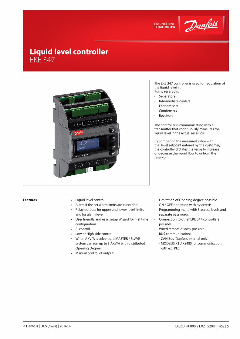
The EKE 347 controller is used for regulation of the liquid level in:Pump reservoirs• Separators• Intermediate coolers• Economisers• Condensers• Receivers
The controller is communicating with a transmitter that continuously measures the liquid level in the actual reservoir.
By comparing the measured value with the level setpoint entered by the customer, the controller dictates the valve to increase or decrease the liquid flow to or from the reservoir.
• Liquid level control• Alarm if the set alarm limits are exceeded• Relay outputs for upper and lower level limits
and for alarm level• User friendly and easy setup Wizard for first time
configuration• PI control• Low or High side control• When AKV/A is selected, a MASTER / SLAVE
system can run up to 3 AKV/A with distributed Opening Degree
• Manual control of output
• Limitation of Opening degree possible• ON / OFF operation with hysteresis• Programming menu with 3 access levels and
separate passwords• Connection to other EKE 347 controllers
possible• Wired remote display possible• BUS communication: - CAN Bus (Danfoss internal only) - MODBUS RTU RS485 for communication
with e.g. PLC
© Danfoss | DCS (mwa) | 2016.096 | DKRCI.PK.000.V1.02 | 520H11462
Liquid level controller, EKE 347
Dan
foss
M84
H00
86_1
PLCMaster
PLCSlave
EKE 347Slave
EKE 347Slave
MODBUS-RTU network
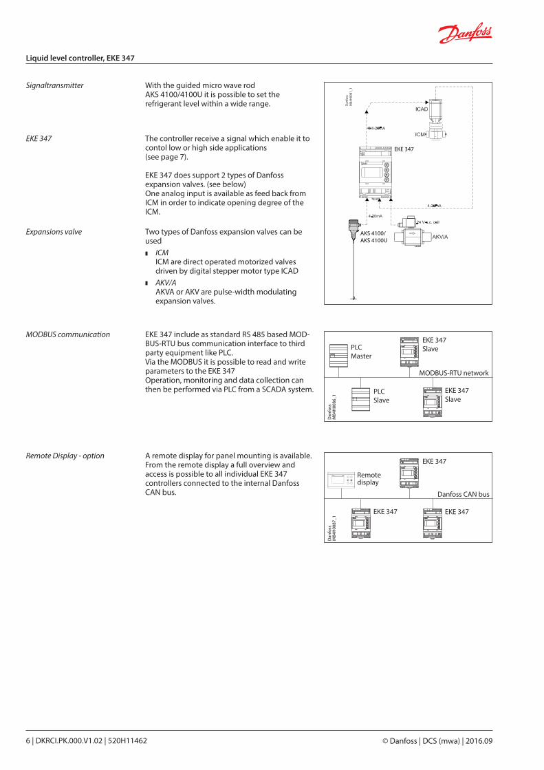
The controller receive a signal which enable it to contol low or high side applications (see page 7).
EKE 347 does support 2 types of Danfoss expansion valves. (see below)One analog input is available as feed back from ICM in order to indicate opening degree of the ICM.
EKE 347 include as standard RS 485 based MOD-BUS-RTU bus communication interface to third party equipment like PLC.Via the MODBUS it is possible to read and write parameters to the EKE 347Operation, monitoring and data collection can then be performed via PLC from a SCADA system.
With the guided micro wave rod AKS 4100/4100U it is possible to set the refrigerant level within a wide range. D
anfo
ssM
84H
0081
_1
AKS 4100/AKS 4100U
EKE 347
Signaltransmitter
EKE 347
Expansions valve Two types of Danfoss expansion valves can be used
ICM ICM are direct operated motorized valves driven by digital stepper motor type ICADAKV/A AKVA or AKV are pulse-width modulating expansion valves.
MODBUS communication
A remote display for panel mounting is available. From the remote display a full overview and access is possible to all individual EKE 347 controllers connected to the internal Danfoss CAN bus.
Remote Display - option
Dan
foss
M84
H00
87_1
Remotedisplay
EKE 347
EKE 347
Danfoss CAN bus
EKE 347
DKRCI.PK.000.V1.02 | 520H11462 | 7© Danfoss | DCS (mwa) | 2016.09
Liquid level controller, EKE 347
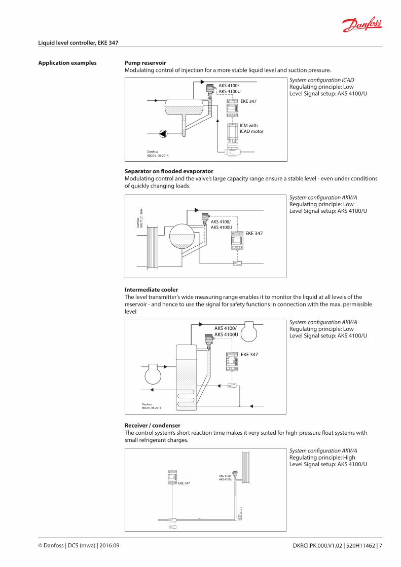
Application examples Pump reservoirModulating control of injection for a more stable liquid level and suction pressure.
Separator on flooded evaporatorModulating control and the valve’s large capacity range ensure a stable level - even under conditions of quickly changing loads.
Intermediate coolerThe level transmitter’s wide measuring range enables it to monitor the liquid at all levels of the reservoir - and hence to use the signal for safety functions in connection with the max. permissible level
Receiver / condenserThe control system’s short reaction time makes it very suited for high-pressure float systems with small refrigerant charges.
ICM withICAD motor
EKE 347
Danfoss80G75_06-2014
AKS 4100/AKS 4100U
Danfoss80G76_06-2014
EKE 347
AKS 4100/AKS 4100U
AKS 4100/AKS 4100UD
anfo
ss80
G77
_01-
2014
EKE 347D
anfo
ss80
G78
_06-
2014
EKE 347
AKS 4100/AKS 4100U
System configuration ICADRegulating principle: LowLevel Signal setup: AKS 4100/U
System configuration AKV/ARegulating principle: LowLevel Signal setup: AKS 4100/U
System configuration AKV/ARegulating principle: LowLevel Signal setup: AKS 4100/U
System configuration AKV/ARegulating principle: HighLevel Signal setup: AKS 4100/U
© Danfoss | DCS (mwa) | 2016.098 | DKRCI.PK.000.V1.02 | 520H11462
Liquid level controller, EKE 347
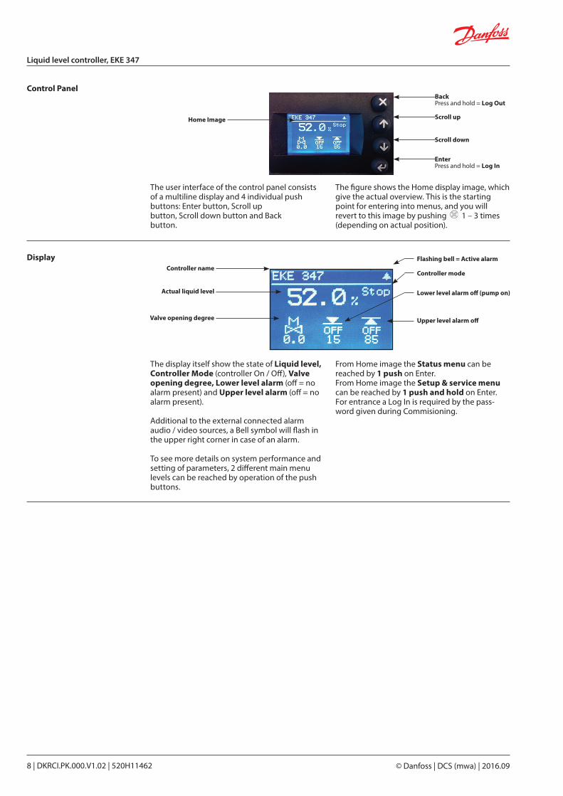
The user interface of the control panel consists of a multiline display and 4 individual push buttons: Enter button, Scroll up button, Scroll down button and Back button.
The figure shows the Home display image, which give the actual overview. This is the starting point for entering into menus, and you will revert to this image by pushing 1 – 3 times (depending on actual position).
Control Panel
The display itself show the state of Liquid level, Controller Mode (controller On / Off), Valve opening degree, Lower level alarm (off = no alarm present) and Upper level alarm (off = no alarm present).
Additional to the external connected alarm audio / video sources, a Bell symbol will flash in the upper right corner in case of an alarm.
To see more details on system performance and setting of parameters, 2 different main menu levels can be reached by operation of the push buttons.
From Home image the Status menu can be reached by 1 push on Enter. From Home image the Setup & service menu can be reached by 1 push and hold on Enter. For entrance a Log In is required by the pass-word given during Commisioning.
Display
BackPress and hold = Log Out
Scroll up
Scroll down
EnterPress and hold = Log In
Home Image
Controller name
Actual liquid level
Valve opening degree
Flashing bell = Active alarm
Controller mode
Lower level alarm off (pump on)
Upper level alarm off
DKRCI.PK.000.V1.02 | 520H11462 | 9© Danfoss | DCS (mwa) | 2016.09
Liquid level controller, EKE 347
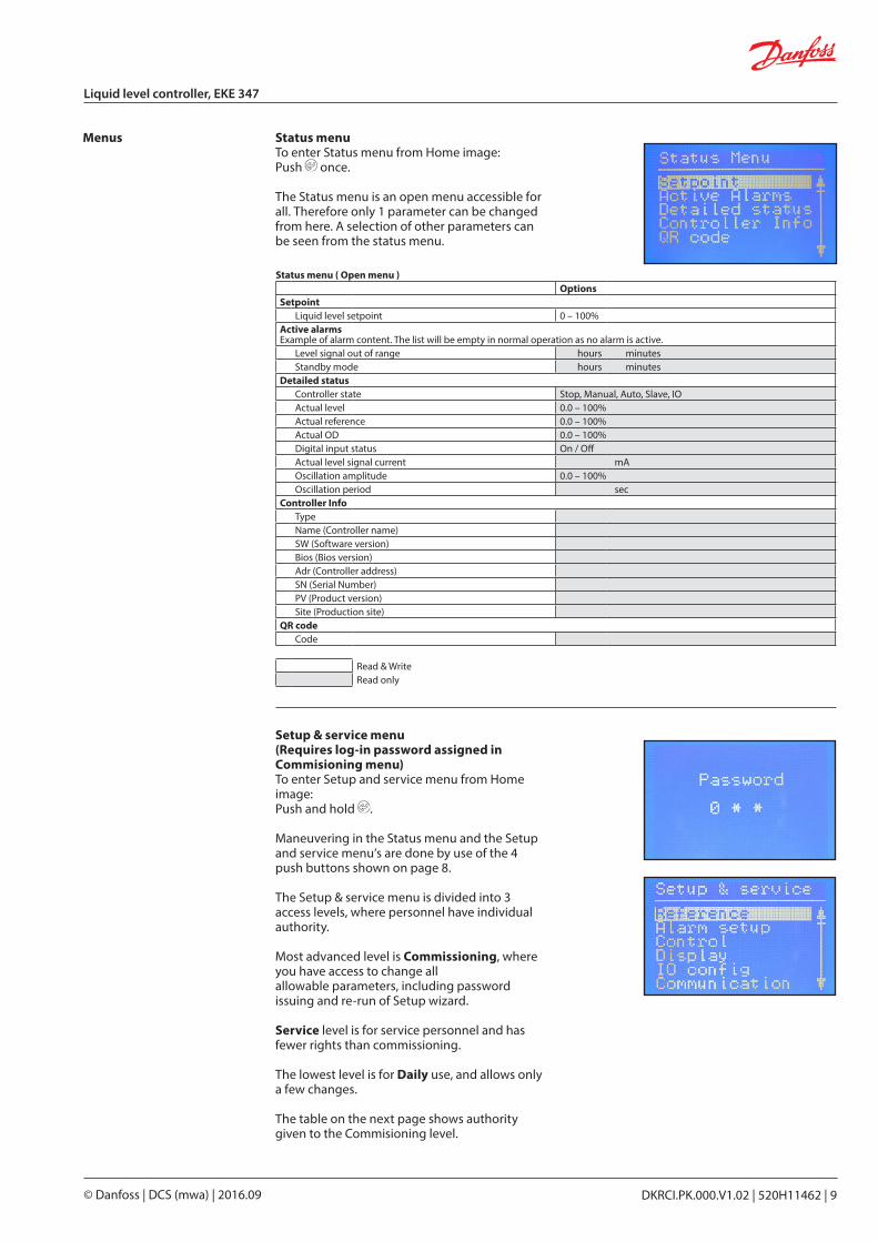
Status menuTo enter Status menu from Home image:Push once.
The Status menu is an open menu accessible for all. Therefore only 1 parameter can be changed from here. A selection of other parameters can be seen from the status menu.
Menus
Setup & service menu(Requires log-in password assigned in Commisioning menu)To enter Setup and service menu from Home image:Push and hold .
Maneuvering in the Status menu and the Setup and service menu’s are done by use of the 4 push buttons shown on page 8.
The Setup & service menu is divided into 3 access levels, where personnel have individual authority.
Most advanced level is Commissioning, where you have access to change all allowable parameters, including password issuing and re-run of Setup wizard.
Service level is for service personnel and has fewer rights than commissioning.
The lowest level is for Daily use, and allows only a few changes.
The table on the next page shows authority given to the Commisioning level.
Status menu ( Open menu )Options
SetpointLiquid level setpoint 0 – 100%
Active alarmsExample of alarm content. The list will be empty in normal operation as no alarm is active.
Level signal out of range hours minutesStandby mode hours minutes
Detailed statusController state Stop, Manual, Auto, Slave, IOActual level 0.0 – 100%Actual reference 0.0 – 100%Actual OD 0.0 – 100%Digital input status On / OffActual level signal current mAOscillation amplitude 0.0 – 100%Oscillation period sec
Controller InfoTypeName (Controller name)SW (Software version)Bios (Bios version)Adr (Controller address)SN (Serial Number)PV (Product version)Site (Production site)
QR codeCode
Read & WriteRead only
© Danfoss | DCS (mwa) | 2016.0910 | DKRCI.PK.000.V1.02 | 520H11462
Liquid level controller, EKE 347
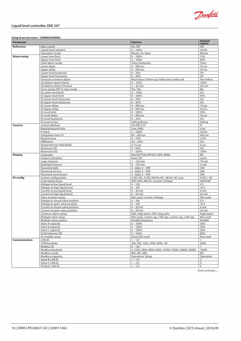
Setup & service menu - COMMISSIONING
Parameter Options Default values
Reference Main switch On, Off OffLiquid level setpoint 0 – 100% 50.0%Operation mode Master, IO, Slave Master
Alarm setup Lower level limit 0 – 100% 15%Upper level limit 0 – 100% 85%Level alarm mode Time, Hysteresis TimeLower delay 0 – 999 sec 10 secUpper delay 0 – 999 sec 50 secLower level hysteresis 0 – 20% 3%Upper level hysteresis 0 – 20% 5%Function common alarm Not follow; Follow up; Follow low; Follow all Not followOscillation detect band 0 – 100% 100%Oscillation detect timeout 2 – 30 min 20 minForce pump OFF in stop mode Yes / No NoIO Lower level limit 0 – 100% 5%IO Upper level limit 0 – 100% 95%IO Lower level hysteresis 0 – 20% 3%IO Upper level hysteresis 0 – 20% 3%IO Lower delay 0 – 999 sec 10 secIO Upper delay 0 – 999 sec 50 secIO Level limit 0 – 100% 50%IO Level delay 0 – 999 sec 10 secIO Level hysteresis 0 – 20% 3%IO Level action Falling,Rising Falling
Control Control Method On/Off ,P, PI PIRegulating principle Low, High LowP-band 5 – 200% 30.0%Integration time Tn 60 – 600 sec 400 secNeutral zone 0 – 25% 2.0%Difference 0,5 – 25% 2%Period time for AKV/AKVA 3–15 sec 6 secMinimum OD 0 – 99% 0%Maximum OD 1 – 100% 100%
Display Language EN,CN,PT,RU,SP,FR,IT, GER, ARAB ENOutput indication level, OD LevelLogin timeout 1 – 120 min 10 minBacklight timeout 0 – 120 min 2 minPassword daily 3 - digit, 0 – 999 100Password service 3 - digit, 0 – 999 200Password commission 3 - digit, 0 – 999 300
IO config System configuration ICAD+NC, ICAD, AKV/A+NC, AKV/A, NC only ICAD + NCLevel signal setup AKS 4100, AKS 41, Current, Voltage AKS4100Voltage at low liquid level 0 – 10V 0 VVoltage at high liquid level 0 – 10V 10 VCurrent at low liquid level 0 – 20 mA 4 mACurrent at high liquid level 0 – 20 mA 20 mAValve position setup Not used, Current, Voltage Not usedVoltage at closed valve position 0 – 10V 0 VVoltage at open valve position 0 – 10V 10 VCurrent at closed valve position 0 – 20 mA 4 mACurrent at open valve position 0 – 20 mA 20 mACommon alarm setup D04, High alarm, D03, Disp only High alarmMultiple valve setup Not used, 2 same cap, 2 dif cap, 3 same cap, 3 dif cap Not usedMultiple valve pattern Parallel,Sequence ParallelValve A capacity 0 – 100% 50%Valve B capacity 0 – 100% 50%Valve C capacity 0 – 100% 30%ICAD takeover OD 0 – 100% 80%IO module setup Used, Not used Not used
Communication CAN ID 1 – 127 1CAN baudrate 20k, 50k, 125k, 250k, 500k, 1M 500kModbus ID 0 – 120 1Modbus baudrate 0, 1200, 2400, 4800, 9600, 14400, 19200, 28800, 38400 19200Modbus mode 8N1, 8E1, 8N2 8E1Modbus mapping Operation, Setup OperationValve B CAN ID 1 – 127 2Valve C CAN ID 1 – 127 3IO Mod. CAN ID 1 – 127 4
To be continued......
DKRCI.PK.000.V1.02 | 520H11462 | 11© Danfoss | DCS (mwa) | 2016.09
Liquid level controller, EKE 347
Setup & service menu - COMMISSIONING (Continued)
Parameter Options Default values
Service Controller state – Actual level – Actual referrence – Actual OD – Actual valve positionDigital input status – Actual level signal voltageActual level signal current – Actual position signal voltageActual position signal currentActual OD AActual OD BActual OD CManual Mode On, Off OffManual OD 0 – 100% 50.0%Manual low alarm Off-On OffManual high alarm Off-On OffManual common alarm Off-On OnApply defaults None, Factory None
Setup wizard Setup wizard Re-run Setup wizard – I/O check Main switch EKE act: Off
AKS 4100 EKE act: – ICAD EKE act: – Nor. Close (NC) EKE act: – Upper lvl (alarm) EKE act: – Lower lvl (alarm) EKE act: –
Controller name Controller name Type in controller name –
Read & Write
Read only
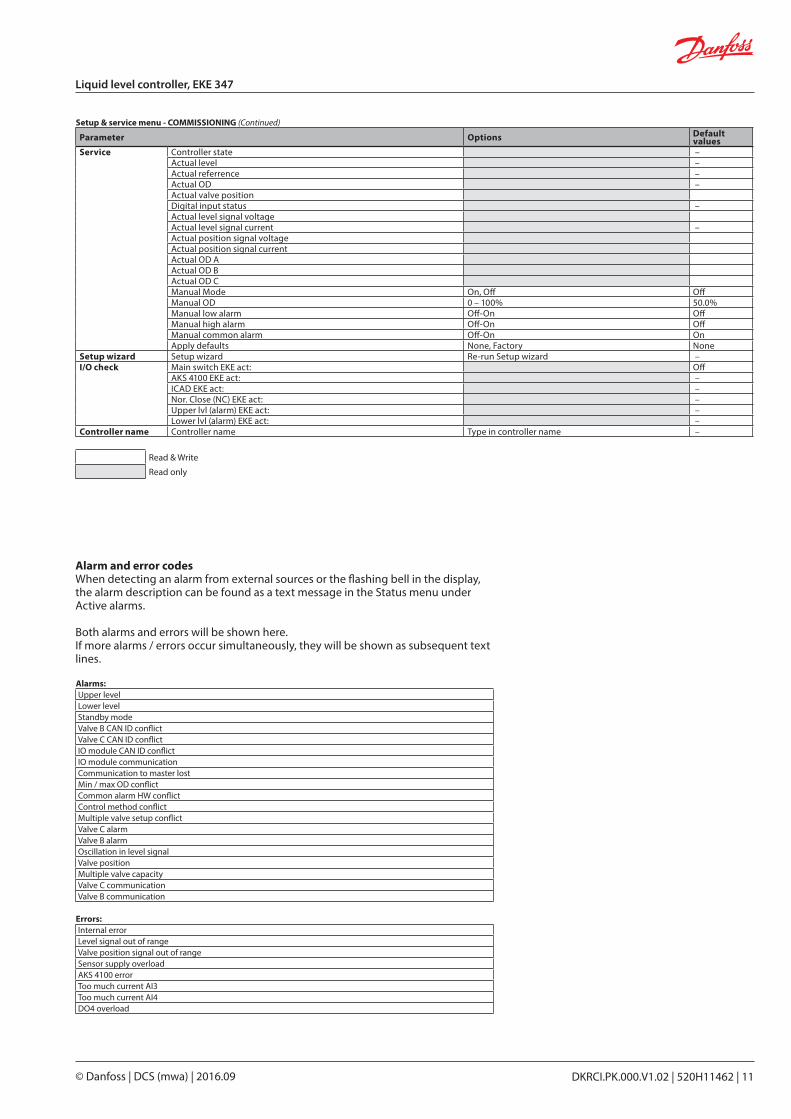
Alarm and error codesWhen detecting an alarm from external sources or the flashing bell in the display, the alarm description can be found as a text message in the Status menu under Active alarms.
Both alarms and errors will be shown here.If more alarms / errors occur simultaneously, they will be shown as subsequent text lines.
Alarms:Upper levelLower levelStandby modeValve B CAN ID conflictValve C CAN ID conflictIO module CAN ID conflictIO module communication Communication to master lostMin / max OD conflictCommon alarm HW conflictControl method conflictMultiple valve setup conflictValve C alarmValve B alarmOscillation in level signalValve positionMultiple valve capacityValve C communicationValve B communication
Errors:Internal errorLevel signal out of rangeValve position signal out of rangeSensor supply overloadAKS 4100 errorToo much current AI3Too much current AI4DO4 overload
© Danfoss | DCS (mwa) | 2016.0912 | DKRCI.PK.000.V1.02 | 520H11462
Liquid level controller, EKE 347
Data
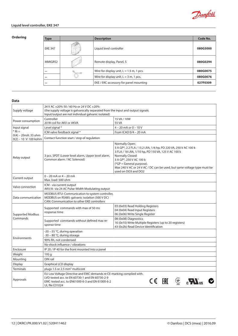
Supply voltage24 V AC ±20% 50 / 60 Hz or 24 V DC ±20%(the supply voltage is galvanically separated from the input and output signals. Input/output are not individual galvanic isolated)
Power consumption Controller20 W coil for AKV or AKVA
15 VA / 10W55 VA
Input signal * Ri =0(4) – 20mA: 33 ohm0(2) – 10 V: 100 kohm
Level signal * 4 – 20 mA or 0 – 10 VICM valve feedback signal * From ICAD 0/4 – 20 mA
Contact function start / stop of regulation
Relay output 3 pcs. SPDT (Lower level alarm, Upper level alarm, Common alarm / NC Solenoid)
Normally Open: 3 A GP*, 2.2 FLA / 13.2 LRA, 1/6 hp, PD 220 VA, 250 V AC 100 k3 FLA / 18 LRA, 1/10 hp, PD 150 VA, 125 V AC 100 kNormally Closed:3 A GP*, 250 V AC 100 k (*GP = General purpose).Max 240 V AC or 24 V AC / DC can be used, but same voltage type must be used on DO3 and DO2
Current output 0 – 20 mA or 4 – 20 mAMax. load: 500 ohm
Valve connection ICM - via current outputAKV/A- via 24 AC Pulse-Width Modulating output
Data communicationMODBUS RTU: Communication to system controller,MODBUS on RS485: galvanic isolation (500 V DC)CAN: Communication to other EKE controllers
Supported Modbus Commands
Supported commands with max of 50 ms response time
03 (0x03) Read Holding Registers04 (0x04) Read Input Registers06 (0x06) Write Single Register
Supported commands without defined max re-sponse time
08 (0x08) Diagnostics16 (0x10) Write Multiple Registers (up to 20 registers)43 (0x2b) Read Device Identification
Environments
-20 – 55 °C, during operation-30 – 80 °C, during storage90% Rh, not condensedNo shock influence / vibrations
Enclosure IP 20 / IP 40 for the front mounted into a panel
Weight 193 g
Mounting DIN rail
Display Graphical LCD display
Terminals plugs 1.5 or 2.5 mm2 multicore
Approvals
EU Low Voltage Directive and EMC demands re CE-marking complied with.LVD-tested acc. to EN 60730-1 and EN 60730-2-9EMC-tested acc. to EN61000-6-3 and EN 61000-6-2UL file E31024
Ordering Type Description Code No.
EKE 347 Liquid level controller 080G5000
MMIGRS2 Remote display, Panel, S 080G0294
– Wire for display unit, L = 1.5 m, 1 pcs. 080G0075
– Wire for display unit, L = 3 m, 1 pcs. 080G0076
– EKE / EKC accessory for panel mounting 027F0309
DKRCI.PK.000.V1.02 | 520H11462 | 13© Danfoss | DCS (mwa) | 2016.09
Liquid level controller, EKE 347
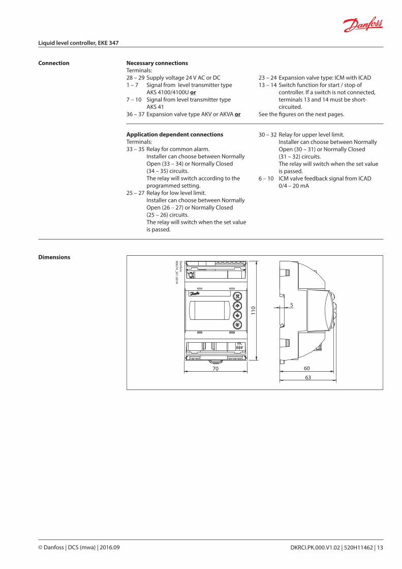
110 5
70 60
63
Danfoss
80G74_}01-2014
Dimensions
Necessary connectionsTerminals:28 – 29 Supply voltage 24 V AC or DC1 – 7 Signal from level transmitter type AKS 4100/4100U or7 – 10 Signal from level transmitter type AKS 4136 – 37 Expansion valve type AKV or AKVA or
Application dependent connectionsTerminals:33 – 35 Relay for common alarm. Installer can choose between Normally Open (33 – 34) or Normally Closed (34 – 35) circuits. The relay will switch according to the programmed setting.25 – 27 Relay for low level limit. Installer can choose between Normally
Open (26 – 27) or Normally Closed (25 – 26) circuits.
The relay will switch when the set value is passed.
23 – 24 Expansion valve type: ICM with ICAD13 – 14 Switch function for start / stop of controller. If a switch is not connected, terminals 13 and 14 must be short- circuited.See the figures on the next pages.
Connection
30 – 32 Relay for upper level limit. Installer can choose between Normally
Open (30 – 31) or Normally Closed (31 – 32) circuits.
The relay will switch when the set value is passed.
6 – 10 ICM valve feedback signal from ICAD 0/4 – 20 mA
© Danfoss | DCS (mwa) | 2016.0914 | DKRCI.PK.000.V1.02 | 520H11462
Liquid level controller, EKE 347
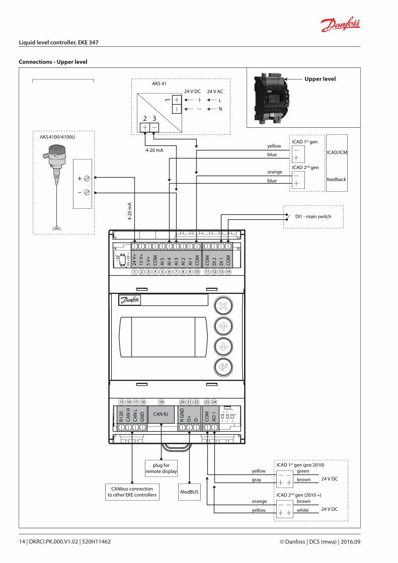
AKS 4100/4100U
AKS 41
Connectionsupper level
DI1 - main switch4-20
mA
CANbus connectionto other EKE controllers
plug forremote display
ModBUS
4-20 mA
24 V DC
yellow
blue
orange
ICAD 1st gen
ICAD/ICM
feedback
ICAD 2nd gen
blue
24 V AC
L
N
+
–
1
2 3
yellow
gray
orange
ICAD 1st gen (pre 2010)
ICAD 2nd gen (2010 +)
yellow
green
brown
brown
white
24 V
+15
V+
5 V+
COM
AI 5
AI 4
AI 3
AI 2
AI 1
COM
COM
DI 2
DI 1
COM
R120
CAN
HCA
N L
GN
D
R G
ND
D+
D-
COM
AO
1CAN RJ
24 V DC
24 V DC
1
15 16 17 18 19 20 21 22 23 24
2 3 4 5 6 7 8 9 10 11 12 13 14
Connections - Upper level
Upper level
DKRCI.PK.000.V1.02 | 520H11462 | 15© Danfoss | DCS (mwa) | 2016.09
Liquid level controller, EKE 347
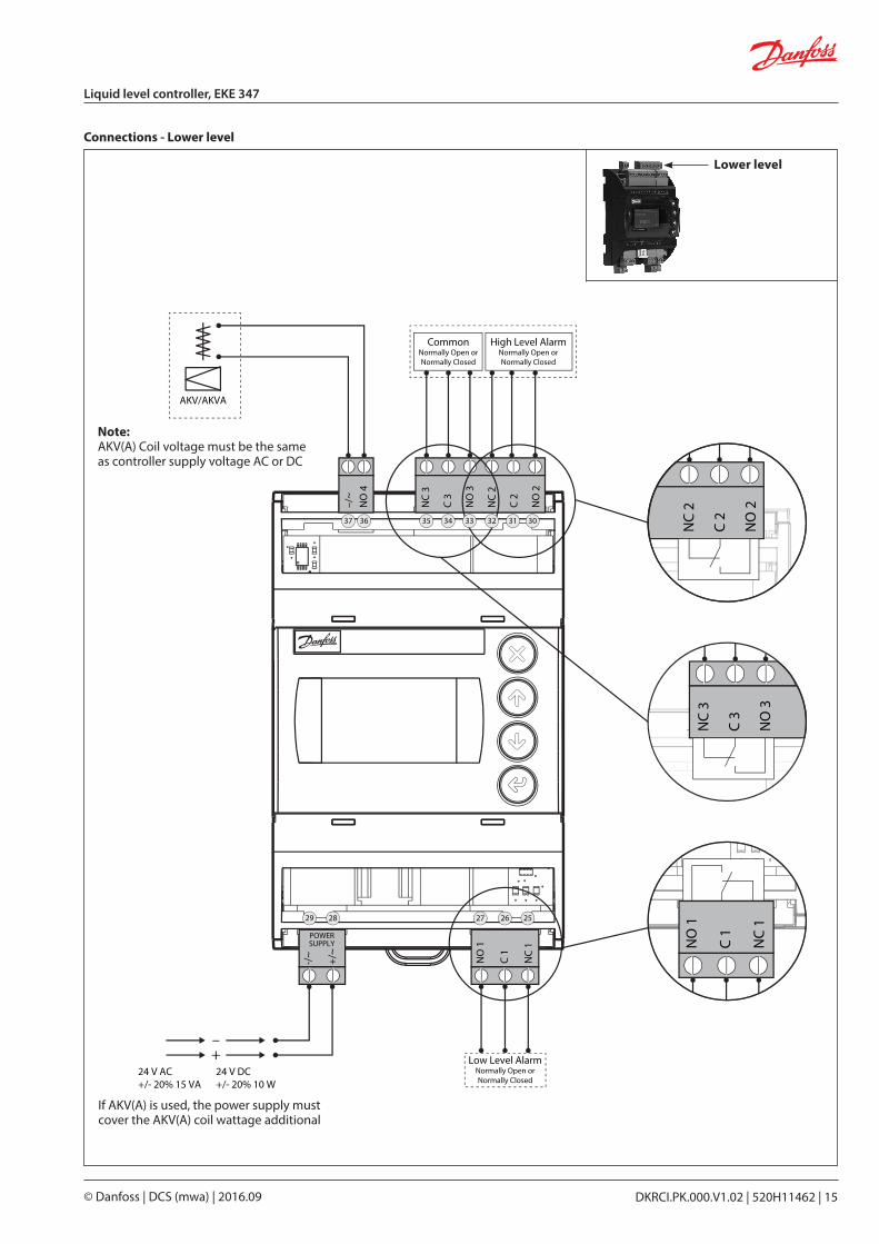
Connections - Lower level
Connectionslower level
–/~
NO
4
NC
3
C 3
NO
3
NC
2
C 2
NO
2
-/~
+/~
NO
1
C 1
NC
1
POWERSUPPLY
AKV/AKVA
24 V AC+/- 20% 15 VA
24 V DC+/- 20% 10 W
–
CommonNormally Open orNormally Closed
Low Level AlarmNormally Open orNormally Closed
High Level AlarmNormally Open orNormally Closed
+
37
29 28 27 26 25
36 35 34 33 32 31 30 NC
2
C 2
NO
2
NC
3
C 3
NO
3
NO
1
C 1
NC
1
Note:AKV(A) Coil voltage must be the same as controller supply voltage AC or DC
If AKV(A) is used, the power supply must cover the AKV(A) coil wattage additional
Lower level
© Danfoss | DCS (mwa) | 2016.0916 | DKRCI.PK.000.V1.02 | 520H11462
Liquid level controller, EKE 347
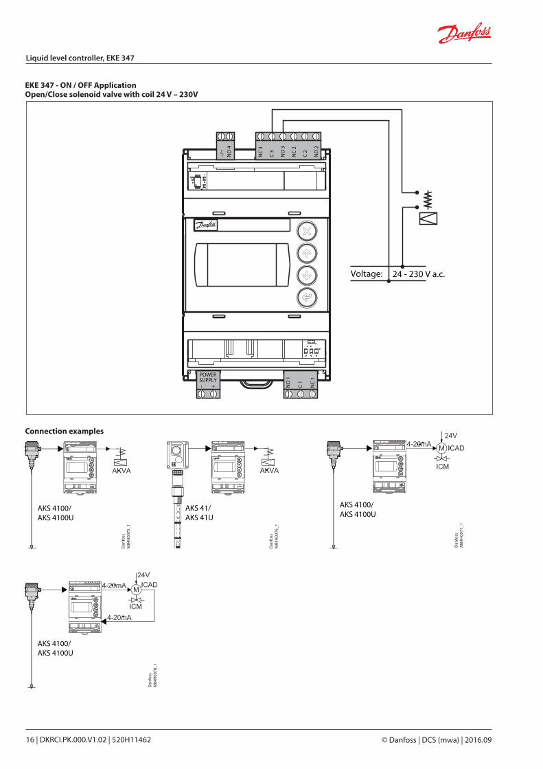
EKE 347 - ON / OFF Application Open/Close solenoid valve with coil 24 V – 230V
–/~
NO
4
NC
3
C 3
NO
3
NC
2
C 2
NO
2
– + NO
1
C 1
NC
1
POWERSUPPLY
Voltage: 24 - 230 V a.c.
Connection examples
AKS 4100/AKS 4100U
Dan
foss
M84
H00
75_1
AKS 41/AKS 41U
Dan
foss
M84
H00
76_1
AKS 4100/AKS 4100U
Dan
foss
M84
H00
77_1
AKS 4100/AKS 4100U
Dan
foss
M84
H00
78_1
DKRCI.PK.000.V1.02 | 520H11462 | 17© Danfoss | DCS (mwa) | 2016.09
Liquid level controller, EKE 347
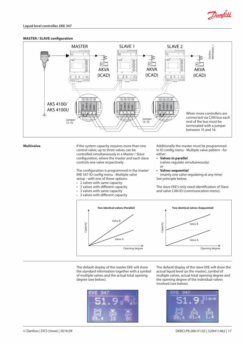
MASTER / SLAVE configuration
When more controllers are connected via CAN bus each end of the bus must be terminated with a jumper between 15 and 16.
AKS 4100/AKS 4100U
Dan
foss
M84
H00
80_1MASTER SLAVE 1 SLAVE 2
AKVA(ICAD)
AKVA(ICAD)
AKVA(ICAD)
R120
CAN
HCA
N L
GN
D
15 16 17 18
R120
CAN
HCA
N L
GN
D
15 16 17 18
R120
CAN
HCA
N L
GN
D
15 16 17 18
Jumper15-16
Jumper15-16
If the system capacity requires more than one control valve; up to three valves can be controlled simultaneously in a Master / Slave configuration, where the master and each slave controls one valve respectively.
The configuration is programmed in the master EKE 347 IO config menu - Multiple valve setup - with one of these options: • 2 valves with same capacity• 2 valves with different capacity• 3 valves with same capacity• 3 valves with different capacity
Multivalve Additionally the master must be programmed in IO config menu - Multiple valve pattern - for either:• Valves in parallel
(valves regulate simultaneously) or
• Valves sequential (mainly one valve regulating at any time)
See principle below.
The slave EKE’s only need identification of Slave and valve CAN ID (communication menu).
The default display of the master EKE will show the standard information together with a symbol of multiple valves and the actual total opening degree (see below).
The default display of the slave EKE will show the actual liquid level (as the master), symbol of multiple valves, actual total opening degree and the opening degree of the individual valves involved (see below).
Capa
city
Capa
city
Opening degreeOpening degree
Valve B
Valve A
Valve B
Valve A
Two identical valves (Parallel) Two identical valves (Sequential)
© Danfoss | DCS (mwa) | 2016.0918 | DKRCI.PK.000.V1.02 | 520H11462
Liquid level controller, EKE 347
AKS 4100/AKS 4100U
Dan
foss
M84
H00
84_1
MASTER I/O
AKVA(ICAD)
R120
CAN
HCA
N L
GN
D
15 16 17 18
R120
CAN
HCA
N L
GN
D
15 16 17 18
Jumper15-16
Jumper15-16
D02
D03
D01
NC
2
C 2
NO
2
NC
3
C 3
NO
3
NO
1
C 1
NC
1
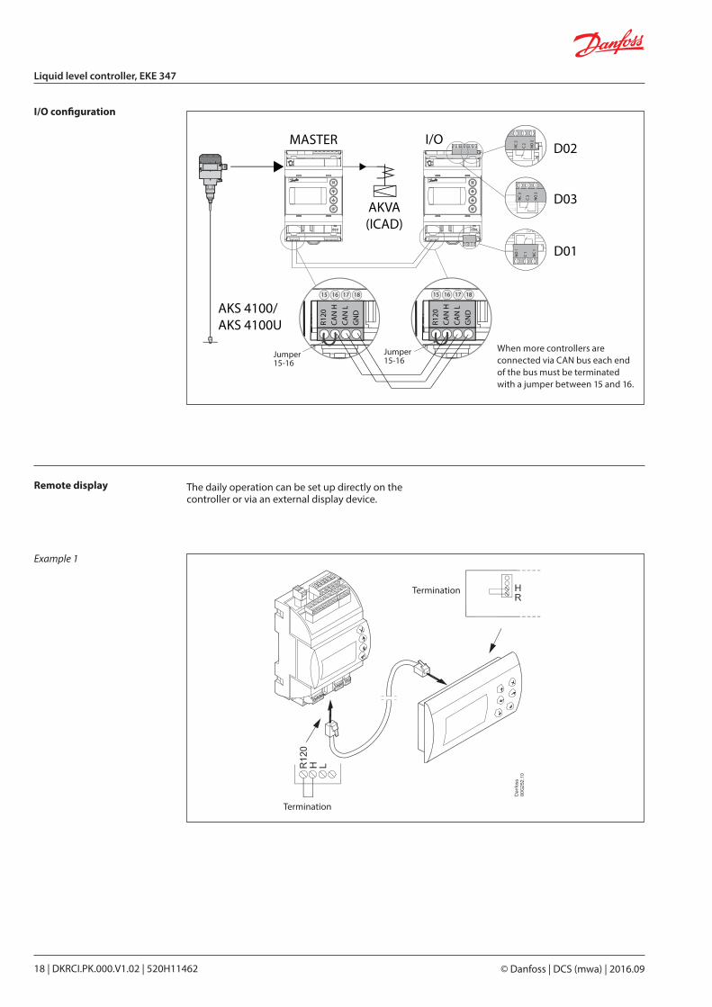
When more controllers are connected via CAN bus each end of the bus must be terminated with a jumper between 15 and 16.
I/O configuration
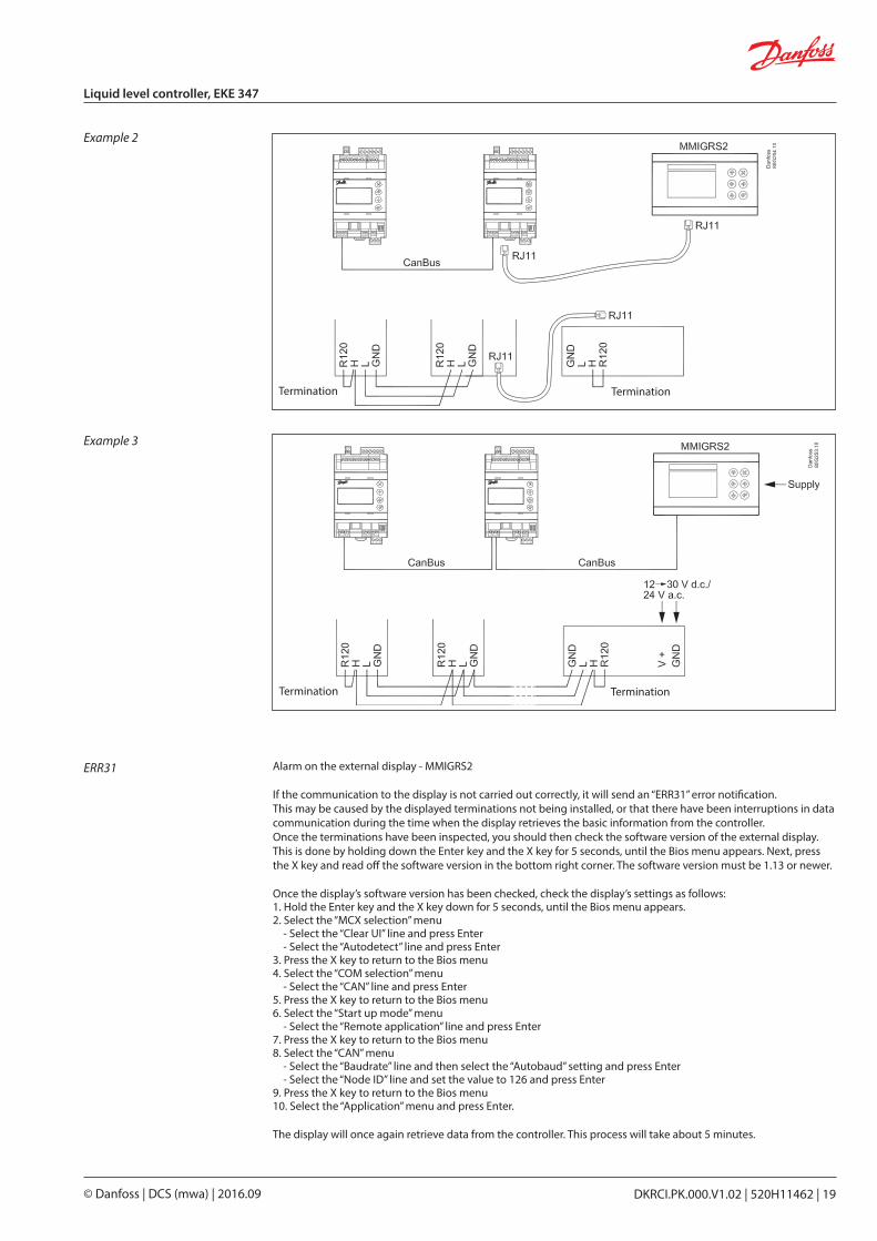
Remote display
Example 1
Termination
Termination
The daily operation can be set up directly on the controller or via an external display device.
DKRCI.PK.000.V1.02 | 520H11462 | 19© Danfoss | DCS (mwa) | 2016.09
Liquid level controller, EKE 347
Alarm on the external display - MMIGRS2
If the communication to the display is not carried out correctly, it will send an “ERR31” error notification. This may be caused by the displayed terminations not being installed, or that there have been interruptions in data communication during the time when the display retrieves the basic information from the controller. Once the terminations have been inspected, you should then check the software version of the external display. This is done by holding down the Enter key and the X key for 5 seconds, until the Bios menu appears. Next, press the X key and read off the software version in the bottom right corner. The software version must be 1.13 or newer.
Once the display’s software version has been checked, check the display’s settings as follows:1. Hold the Enter key and the X key down for 5 seconds, until the Bios menu appears. 2. Select the “MCX selection” menu - Select the “Clear UI” line and press Enter - Select the “Autodetect” line and press Enter3. Press the X key to return to the Bios menu4. Select the “COM selection” menu - Select the “CAN” line and press Enter 5. Press the X key to return to the Bios menu 6. Select the “Start up mode” menu - Select the “Remote application” line and press Enter 7. Press the X key to return to the Bios menu 8. Select the “CAN” menu - Select the “Baudrate” line and then select the “Autobaud” setting and press Enter - Select the “Node ID” line and set the value to 126 and press Enter9. Press the X key to return to the Bios menu 10. Select the “Application” menu and press Enter.
The display will once again retrieve data from the controller. This process will take about 5 minutes.
ERR31
Example 3
Example 2
Termination
Termination
Termination
Termination
© Danfoss | DCS (mwa) | 2016.0920 | DKRCI.PK.000.V1.02 | 520H11462
Liquid level controller, EKE 347
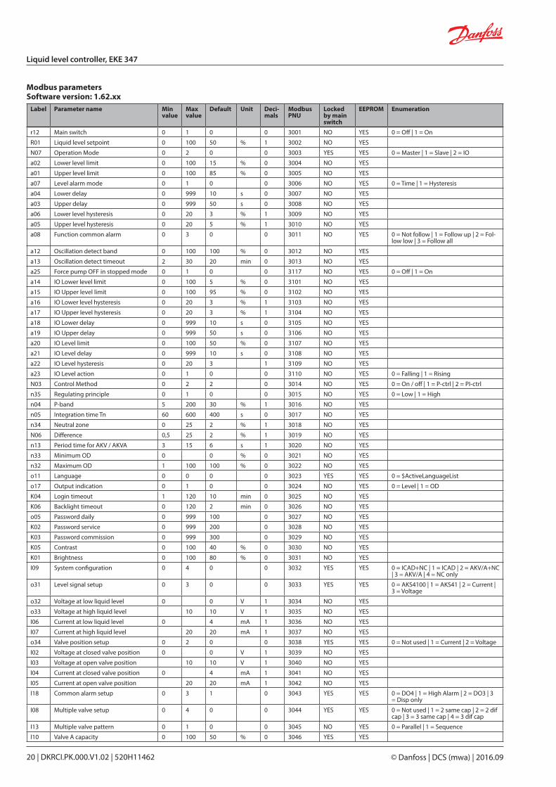
Label Parameter name Min value
Max value
Default Unit Deci-mals
Modbus PNU
Locked by main switch
EEPROM Enumeration
r12 Main switch 0 1 0 0 3001 NO YES 0 = Off | 1 = On
R01 Liquid level setpoint 0 100 50 % 1 3002 NO YES
N07 Operation Mode 0 2 0 0 3003 YES YES 0 = Master | 1 = Slave | 2 = IO
a02 Lower level limit 0 100 15 % 0 3004 NO YES
a01 Upper level limit 0 100 85 % 0 3005 NO YES
a07 Level alarm mode 0 1 0 0 3006 NO YES 0 = Time | 1 = Hysteresis
a04 Lower delay 0 999 10 s 0 3007 NO YES
a03 Upper delay 0 999 50 s 0 3008 NO YES
a06 Lower level hysteresis 0 20 3 % 1 3009 NO YES
a05 Upper level hysteresis 0 20 5 % 1 3010 NO YES
a08 Function common alarm 0 3 0 0 3011 NO YES 0 = Not follow | 1 = Follow up | 2 = Fol-low low | 3 = Follow all
a12 Oscillation detect band 0 100 100 % 0 3012 NO YES
a13 Oscillation detect timeout 2 30 20 min 0 3013 NO YES
a25 Force pump OFF in stopped mode 0 1 0 0 3117 NO YES 0 = Off | 1 = On
a14 IO Lower level limit 0 100 5 % 0 3101 NO YES
a15 IO Upper level limit 0 100 95 % 0 3102 NO YES
a16 IO Lower level hysteresis 0 20 3 % 1 3103 NO YES
a17 IO Upper level hysteresis 0 20 3 % 1 3104 NO YES
a18 IO Lower delay 0 999 10 s 0 3105 NO YES
a19 IO Upper delay 0 999 50 s 0 3106 NO YES
a20 IO Level limit 0 100 50 % 0 3107 NO YES
a21 IO Level delay 0 999 10 s 0 3108 NO YES
a22 IO Level hysteresis 0 20 3 1 3109 NO YES
a23 IO Level action 0 1 0 0 3110 NO YES 0 = Falling | 1 = Rising
N03 Control Method 0 2 2 0 3014 NO YES 0 = On / off | 1 = P-ctrl | 2 = PI-ctrl
n35 Regulating principle 0 1 0 0 3015 NO YES 0 = Low | 1 = High
n04 P-band 5 200 30 % 1 3016 NO YES
n05 Integration time Tn 60 600 400 s 0 3017 NO YES
n34 Neutral zone 0 25 2 % 1 3018 NO YES
N06 Difference 0,5 25 2 % 1 3019 NO YES
n13 Period time for AKV / AKVA 3 15 6 s 1 3020 NO YES
n33 Minimum OD 0 0 % 0 3021 NO YES
n32 Maximum OD 1 100 100 % 0 3022 NO YES
o11 Language 0 0 0 0 3023 YES YES 0 = $ActiveLanguageList
o17 Output indication 0 1 0 0 3024 NO YES 0 = Level | 1 = OD
K04 Login timeout 1 120 10 min 0 3025 NO YES
K06 Backlight timeout 0 120 2 min 0 3026 NO YES
o05 Password daily 0 999 100 0 3027 NO YES
K02 Password service 0 999 200 0 3028 NO YES
K03 Password commission 0 999 300 0 3029 NO YES
K05 Contrast 0 100 40 % 0 3030 NO YES
K01 Brightness 0 100 80 % 0 3031 NO YES
I09 System configuration 0 4 0 0 3032 YES YES 0 = ICAD+NC | 1 = ICAD | 2 = AKV/A+NC | 3 = AKV/A | 4 = NC only
o31 Level signal setup 0 3 0 0 3033 YES YES 0 = AKS4100 | 1 = AKS41 | 2 = Current | 3 = Voltage
o32 Voltage at low liquid level 0 0 V 1 3034 NO YES
o33 Voltage at high liquid level 10 10 V 1 3035 NO YES
I06 Current at low liquid level 0 4 mA 1 3036 NO YES
I07 Current at high liquid level 20 20 mA 1 3037 NO YES
o34 Valve position setup 0 2 0 0 3038 YES YES 0 = Not used | 1 = Current | 2 = Voltage
I02 Voltage at closed valve position 0 0 V 1 3039 NO YES
I03 Voltage at open valve position 10 10 V 1 3040 NO YES
I04 Current at closed valve position 0 4 mA 1 3041 NO YES
I05 Current at open valve position 20 20 mA 1 3042 NO YES
I18 Common alarm setup 0 3 1 0 3043 YES YES 0 = DO4 | 1 = High Alarm | 2 = DO3 | 3 = Disp only
I08 Multiple valve setup 0 4 0 0 3044 YES YES 0 = Not used | 1 = 2 same cap | 2 = 2 dif cap | 3 = 3 same cap | 4 = 3 dif cap
I13 Multiple valve pattern 0 1 0 0 3045 NO YES 0 = Parallel | 1 = Sequence
I10 Valve A capacity 0 100 50 % 0 3046 YES YES
Modbus parametersSoftware version: 1.62.xx
DKRCI.PK.000.V1.02 | 520H11462 | 21© Danfoss | DCS (mwa) | 2016.09
Liquid level controller, EKE 347
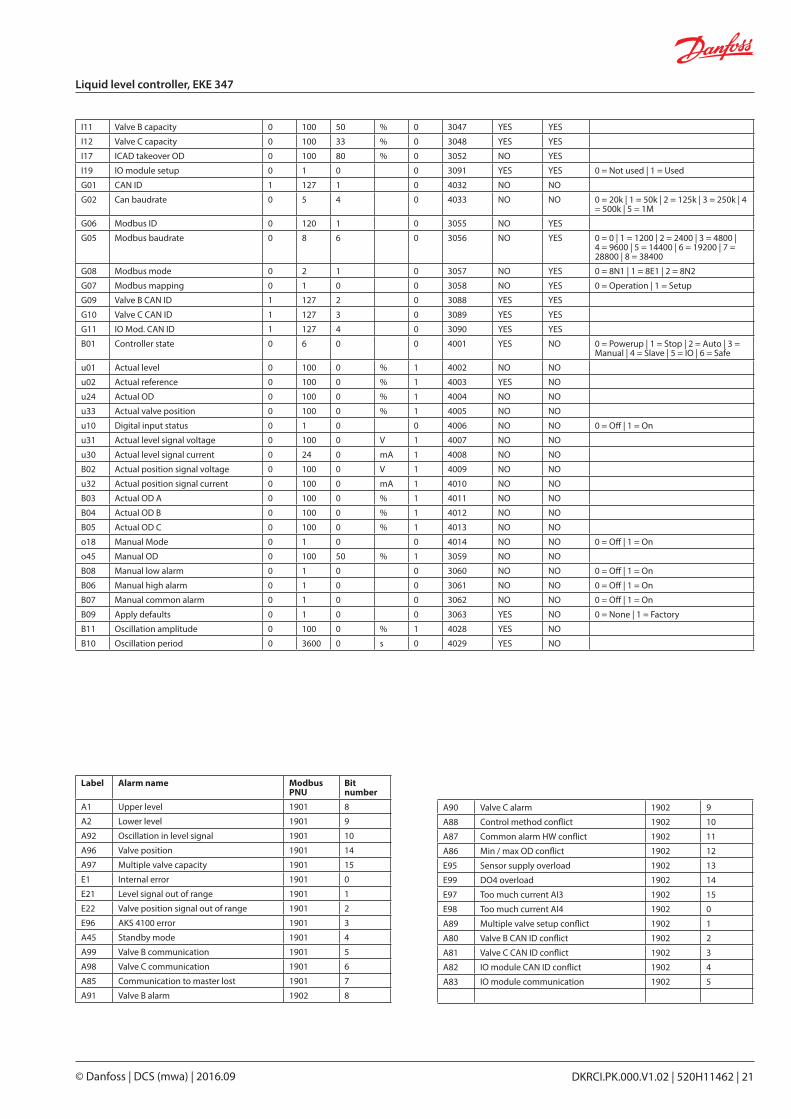
Label Alarm name Modbus PNU
Bit number
A1 Upper level 1901 8
A2 Lower level 1901 9
A92 Oscillation in level signal 1901 10
A96 Valve position 1901 14
A97 Multiple valve capacity 1901 15
E1 Internal error 1901 0
E21 Level signal out of range 1901 1
E22 Valve position signal out of range 1901 2
E96 AKS 4100 error 1901 3
A45 Standby mode 1901 4
A99 Valve B communication 1901 5
A98 Valve C communication 1901 6
A85 Communication to master lost 1901 7
A91 Valve B alarm 1902 8
I11 Valve B capacity 0 100 50 % 0 3047 YES YES
I12 Valve C capacity 0 100 33 % 0 3048 YES YES
I17 ICAD takeover OD 0 100 80 % 0 3052 NO YES
I19 IO module setup 0 1 0 0 3091 YES YES 0 = Not used | 1 = Used
G01 CAN ID 1 127 1 0 4032 NO NO
G02 Can baudrate 0 5 4 0 4033 NO NO 0 = 20k | 1 = 50k | 2 = 125k | 3 = 250k | 4 = 500k | 5 = 1M
G06 Modbus ID 0 120 1 0 3055 NO YES
G05 Modbus baudrate 0 8 6 0 3056 NO YES 0 = 0 | 1 = 1200 | 2 = 2400 | 3 = 4800 | 4 = 9600 | 5 = 14400 | 6 = 19200 | 7 = 28800 | 8 = 38400
G08 Modbus mode 0 2 1 0 3057 NO YES 0 = 8N1 | 1 = 8E1 | 2 = 8N2
G07 Modbus mapping 0 1 0 0 3058 NO YES 0 = Operation | 1 = Setup
G09 Valve B CAN ID 1 127 2 0 3088 YES YES
G10 Valve C CAN ID 1 127 3 0 3089 YES YES
G11 IO Mod. CAN ID 1 127 4 0 3090 YES YES
B01 Controller state 0 6 0 0 4001 YES NO 0 = Powerup | 1 = Stop | 2 = Auto | 3 = Manual | 4 = Slave | 5 = IO | 6 = Safe
u01 Actual level 0 100 0 % 1 4002 NO NO
u02 Actual reference 0 100 0 % 1 4003 YES NO
u24 Actual OD 0 100 0 % 1 4004 NO NO
u33 Actual valve position 0 100 0 % 1 4005 NO NO
u10 Digital input status 0 1 0 0 4006 NO NO 0 = Off | 1 = On
u31 Actual level signal voltage 0 100 0 V 1 4007 NO NO
u30 Actual level signal current 0 24 0 mA 1 4008 NO NO
B02 Actual position signal voltage 0 100 0 V 1 4009 NO NO
u32 Actual position signal current 0 100 0 mA 1 4010 NO NO
B03 Actual OD A 0 100 0 % 1 4011 NO NO
B04 Actual OD B 0 100 0 % 1 4012 NO NO
B05 Actual OD C 0 100 0 % 1 4013 NO NO
o18 Manual Mode 0 1 0 0 4014 NO NO 0 = Off | 1 = On
o45 Manual OD 0 100 50 % 1 3059 NO NO
B08 Manual low alarm 0 1 0 0 3060 NO NO 0 = Off | 1 = On
B06 Manual high alarm 0 1 0 0 3061 NO NO 0 = Off | 1 = On
B07 Manual common alarm 0 1 0 0 3062 NO NO 0 = Off | 1 = On
B09 Apply defaults 0 1 0 0 3063 YES NO 0 = None | 1 = Factory
B11 Oscillation amplitude 0 100 0 % 1 4028 YES NO
B10 Oscillation period 0 3600 0 s 0 4029 YES NO
A90 Valve C alarm 1902 9
A88 Control method conflict 1902 10
A87 Common alarm HW conflict 1902 11
A86 Min / max OD conflict 1902 12
E95 Sensor supply overload 1902 13
E99 DO4 overload 1902 14
E97 Too much current AI3 1902 15
E98 Too much current AI4 1902 0
A89 Multiple valve setup conflict 1902 1
A80 Valve B CAN ID conflict 1902 2
A81 Valve C CAN ID conflict 1902 3
A82 IO module CAN ID conflict 1902 4
A83 IO module communication 1902 5

Shut-off and regulating valves for Industrial Refrigeration
DKRCI.PK.000.V1.02 | 520H11462 | 23© Danfoss | DCS (mwa) | 2016.09
Media temperature controllerEKC 361
DKRCI.PS.RP0.B2.02 | 2015.11
Contents Page
Features . . . . . . . . . . . . . . . . . . . . . . . . . . . . . . . . . . . . . . . . . . . . . . . . . . . . . . . . . . . . . . . . . . . . . . . . . . . . . . . . . . . . . . . . . . 25
Introduction. . . . . . . . . . . . . . . . . . . . . . . . . . . . . . . . . . . . . . . . . . . . . . . . . . . . . . . . . . . . . . . . . . . . . . . . . . . . . . . . . . . . . . 26
Application examples. . . . . . . . . . . . . . . . . . . . . . . . . . . . . . . . . . . . . . . . . . . . . . . . . . . . . . . . . . . . . . . . . . . . . . . . . . . . . 27
Extra options . . . . . . . . . . . . . . . . . . . . . . . . . . . . . . . . . . . . . . . . . . . . . . . . . . . . . . . . . . . . . . . . . . . . . . . . . . . . . . . . . . . . . 27
Function . . . . . . . . . . . . . . . . . . . . . . . . . . . . . . . . . . . . . . . . . . . . . . . . . . . . . . . . . . . . . . . . . . . . . . . . . . . . . . . . . . . . . . . . . 28
Survey of functions . . . . . . . . . . . . . . . . . . . . . . . . . . . . . . . . . . . . . . . . . . . . . . . . . . . . . . . . . . . . . . . . . . . . . . . . . . . . . . . 29
Operation . . . . . . . . . . . . . . . . . . . . . . . . . . . . . . . . . . . . . . . . . . . . . . . . . . . . . . . . . . . . . . . . . . . . . . . . . . . . . . . . . . . . . . . . 32
Menu survey . . . . . . . . . . . . . . . . . . . . . . . . . . . . . . . . . . . . . . . . . . . . . . . . . . . . . . . . . . . . . . . . . . . . . . . . . . . . . . . . . . . . . 32
Data. . . . . . . . . . . . . . . . . . . . . . . . . . . . . . . . . . . . . . . . . . . . . . . . . . . . . . . . . . . . . . . . . . . . . . . . . . . . . . . . . . . . . . . . . . . . . . 33
Connections. . . . . . . . . . . . . . . . . . . . . . . . . . . . . . . . . . . . . . . . . . . . . . . . . . . . . . . . . . . . . . . . . . . . . . . . . . . . . . . . . . . . . . 33
Ordering . . . . . . . . . . . . . . . . . . . . . . . . . . . . . . . . . . . . . . . . . . . . . . . . . . . . . . . . . . . . . . . . . . . . . . . . . . . . . . . . . . . . . . . . . 33
Data communication . . . . . . . . . . . . . . . . . . . . . . . . . . . . . . . . . . . . . . . . . . . . . . . . . . . . . . . . . . . . . . . . . . . . . . . . . . . . . 34
Start of controller . . . . . . . . . . . . . . . . . . . . . . . . . . . . . . . . . . . . . . . . . . . . . . . . . . . . . . . . . . . . . . . . . . . . . . . . . . . . . . . . . 36
If the temperature fluctuates . . . . . . . . . . . . . . . . . . . . . . . . . . . . . . . . . . . . . . . . . . . . . . . . . . . . . . . . . . . . . . . . . . . . . . 36
Trouble shooting - ICS / PM with CVQ. . . . . . . . . . . . . . . . . . . . . . . . . . . . . . . . . . . . . . . . . . . . . . . . . . . . . . . . . . . . . . 36
Fine adjustments . . . . . . . . . . . . . . . . . . . . . . . . . . . . . . . . . . . . . . . . . . . . . . . . . . . . . . . . . . . . . . . . . . . . . . . . . . . . . . . . . 37


Shut-off and regulating valves for Industrial Refrigeration
DKRCI.PK.000.V1.02 | 520H11462 | 25© Danfoss | DCS (mwa) | 2016.09
Media temperature controllerEKC 361
Features • The temperature is kept within an accuracy of ±0.25 °C or better after a transient phenomenon
• The evaporator's temperature is kept as high as possible, so that the air humidity is kept high and waste is limited
• A transient phenomenon can be controlled with the adaptive function. Select either: - Fast build-up where underswings are allowed - Not quite so fast build-up where under swings are less pronounced - Build-up without underswings
• PID regulation
• p0 limitation
The controller and valve can be used where there are stringent requirements to accurate temperature control in connection with refrigeration.
E.g.:• Cold room for fruits and food products• Refrigerating systems• Work premises in the food industry • Process cooling of liquids
© Danfoss | DCS (mwa) | 2016.0926 | DKRCI.PK.000.V1.02 | 520H11462
Media temperature controller, EKC 361
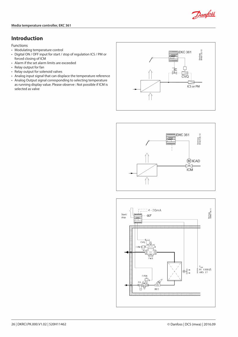
IntroductionFunctions• Modulating temperature control• Digital ON / OFF input for start / stop of regulation ICS / PM or forced closing of ICM• Alarm if the set alarm limits are exceeded• Relay output for fan• Relay output for solenoid valves• Analog input signal that can displace the temperature reference• Analog Output signal corresponding to selecting temperature as running display value. Please observe : Not possible if ICM is selected as valve
Start/stop
ICS or PM
DKRCI.PK.000.V1.02 | 520H11462 | 27© Danfoss | DCS (mwa) | 2016.09
Media temperature controller, EKC 361
Application examples
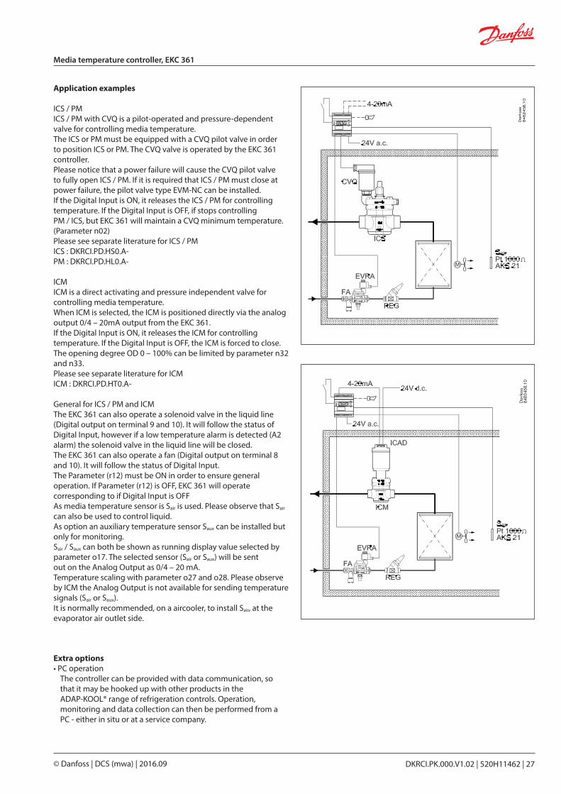
ICS / PMICS / PM with CVQ is a pilot-operated and pressure-dependent valve for controlling media temperature.The ICS or PM must be equipped with a CVQ pilot valve in order to position ICS or PM. The CVQ valve is operated by the EKC 361 controller.Please notice that a power failure will cause the CVQ pilot valve to fully open ICS / PM. If it is required that ICS / PM must close at power failure, the pilot valve type EVM-NC can be installed.If the Digital Input is ON, it releases the ICS / PM for controlling temperature. If the Digital Input is OFF, if stops controlling PM / ICS, but EKC 361 will maintain a CVQ minimum temperature. (Parameter n02)Please see separate literature for ICS / PMICS : DKRCI.PD.HS0.A-PM : DKRCI.PD.HL0.A-
ICMICM is a direct activating and pressure independent valve for controlling media temperature.When ICM is selected, the ICM is positioned directly via the analog output 0/4 – 20mA output from the EKC 361.If the Digital Input is ON, it releases the ICM for controlling temperature. If the Digital Input is OFF, the ICM is forced to close.The opening degree OD 0 – 100% can be limited by parameter n32 and n33.Please see separate literature for ICMICM : DKRCI.PD.HT0.A-
General for ICS / PM and ICMThe EKC 361 can also operate a solenoid valve in the liquid line (Digital output on terminal 9 and 10). It will follow the status of Digital Input, however if a low temperature alarm is detected (A2 alarm) the solenoid valve in the liquid line will be closed.The EKC 361 can also operate a fan (Digital output on terminal 8 and 10). It will follow the status of Digital Input.The Parameter (r12) must be ON in order to ensure general operation. If Parameter (r12) is OFF, EKC 361 will operate corresponding to if Digital Input is OFFAs media temperature sensor is Sair is used. Please observe that Sair can also be used to control liquid.As option an auxiliary temperature sensor Saux can be installed but only for monitoring.Sair / Saux can both be shown as running display value selected by parameter o17. The selected sensor (Sair or Saux) will be sentout on the Analog Output as 0/4 – 20 mA.Temperature scaling with parameter o27 and o28. Please observe by ICM the Analog Output is not available for sending temperature signals (Sair or Saux).It is normally recommended, on a aircooler, to install Sair, at the evaporator air outlet side.
Extra options• PC operation
The controller can be provided with data communication, so that it may be hooked up with other products in the ADAP-KOOL® range of refrigeration controls. Operation, moni toring and data collection can then be performed from a PC - either in situ or at a service company.
© Danfoss | DCS (mwa) | 2016.0928 | DKRCI.PK.000.V1.02 | 520H11462
Media temperature controller, EKC 361
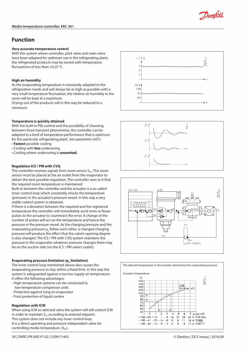
FunctionVery accurate temperature controlWith this system where controller, pilot valve and main valve have been adapted for optimum use in the refrigerating plant, the refrigerated products may be stored with temperature fluctuations of less than ±0.25 °C.
High air humidityAs the evaporating temperature is constantly adapted to the refrigeration needs and will always be as high as possible with a very small temperature fluctuation, the relative air humidity in the room will be kept at a maximum.Drying-out of the products will in this way be reduced to a minimum.
Temperature is quickly attainedWith the built-in PID control and the possibility of choosing between three transient phenomena, the controller can be adapted to a kind of temperature performance that is optimum for this particular refrigerating plant. See parameter (n07).• Fastest possible cooling• Cooling with less underswing• Cooling where underswing is unwanted.
Regulation ICS / PM with CVQThe controller receives signals from room sensor Sair. This room sensor must be placed at the air outlet from the evaporator to obtain the best possible regulation. The controller sees to it that the required room temperature is maintained.Built-in between the controller and the actuator is a so-called inner control loop which constantly checks the temperature (pressure) in the actuator’s pressure vessel. In this way a very stable control system is obtained.If there is a deviation between the required and the registered temperature the controller will immediately send more or fewer pulses to the actuator to counteract the error. A change of the number of pulses will act on the temperature and hence the pressure in the pressure vessel. As the charging pressure and the evaporating pressure p0 follow each other, a changed charging pressure will produce the effect that the valve’s opening degree is also changed. The ICS / PM with CVQ system maintains the pressure in the evaporator whatever pressure changes there may be on the suction side (on the ICS / PM valve’s outlet).
Evaporating pressure limitation (p0 limitation)The inner control loop mentioned above also causes the evapora ting pressure to stay within a fixed limit. In this way the system is safeguarded against a too low supply air temperature.It offers the following advantages:- High-temperature systems can be connected to
low-tempera ture compressor units- Protection against icing on evaporator- Frost protection of liquid coolers
Regulation with ICMWhen using ICM as selected valve the system will still control ICM in order to maintain Sair according to entered setpoint.This system does not include any inner control loop.It is a direct operating and pressure independent valve for controlling media temperature. (Sair).
The allowed temperature in the actuator determines the evapora ting pressure
Actuator temperature
© Danfoss | DCS (mwa) | 2016.0929 | DKRCI.PK.000.V1.02 | 520H11462
Media temperature controller, EKC 361
Survey of functionsFunction Para-
meterParameter by operation via data com-munication
Normal display
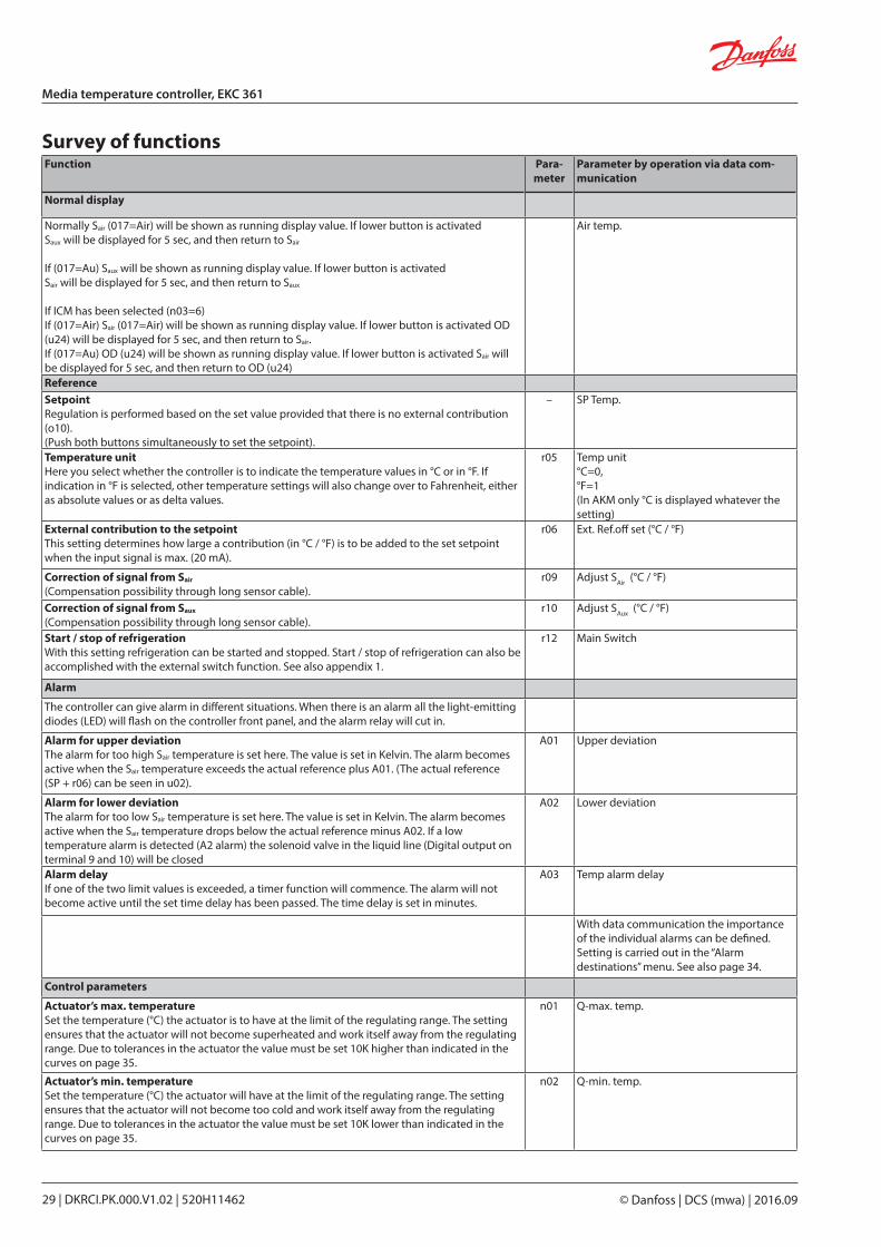
Normally Sair (017=Air) will be shown as running display value. If lower button is activatedSaux will be displayed for 5 sec, and then return to Sair
If (017=Au) Saux will be shown as running display value. If lower button is activatedSair will be displayed for 5 sec, and then return to Saux
If ICM has been selected (n03=6)If (017=Air) Sair (017=Air) will be shown as running display value. If lower button is activated OD (u24) will be displayed for 5 sec, and then return to Sair.If (017=Au) OD (u24) will be shown as running display value. If lower button is activated Sair will be displayed for 5 sec, and then return to OD (u24)
Air temp.
ReferenceSetpointRegulation is performed based on the set value provided that there is no external contribution (o10).(Push both buttons simultaneously to set the setpoint).
– SP Temp.
Temperature unitHere you select whether the controller is to indicate the temperature values in °C or in °F. If indication in °F is selected, other temperature settings will also change over to Fahrenheit, either as absolute values or as delta values.
r05 Temp unit°C=0, °F=1(In AKM only °C is displayed whatever the setting)
External contribution to the setpointThis setting determines how large a contribution (in °C / °F) is to be added to the set setpoint when the input signal is max. (20 mA).
r06 Ext. Ref.off set (°C / °F)
Correction of signal from Sair
(Compensation possibility through long sensor cable).r09 Adjust SAir (°C / °F)
Correction of signal from Saux
(Compensation possibility through long sensor cable).r10 Adjust SAux (°C / °F)
Start / stop of refrigerationWith this setting refrigeration can be started and stopped. Start / stop of refrigeration can also be accomplished with the external switch function. See also appendix 1.
r12 Main Switch
Alarm
The controller can give alarm in different situations. When there is an alarm all the light-emitting diodes (LED) will flash on the controller front panel, and the alarm relay will cut in.
Alarm for upper deviationThe alarm for too high Sair temperature is set here. The value is set in Kelvin. The alarm becomes active when the Sair temperature exceeds the actual reference plus A01. (The actual reference (SP + r06) can be seen in u02).
A01 Upper deviation
Alarm for lower deviationThe alarm for too low Sair temperature is set here. The value is set in Kelvin. The alarm becomes active when the Sair temperature drops below the actual reference minus A02. If a low temperature alarm is detected (A2 alarm) the solenoid valve in the liquid line (Digital output on terminal 9 and 10) will be closed
A02 Lower deviation
Alarm delayIf one of the two limit values is exceeded, a timer function will commence. The alarm will not become active until the set time delay has been passed. The time delay is set in minutes.
A03 Temp alarm delay
With data communication the importance of the individual alarms can be defined. Setting is carried out in the “Alarm destinations” menu. See also page 34.
Control parameters
Actuator’s max. temperatureSet the temperature (°C) the actuator is to have at the limit of the regulating range. The setting ensures that the actuator will not become superheated and work itself away from the regulating range. Due to tolerances in the actuator the value must be set 10K higher than indicated in the curves on page 35.
n01 Q-max. temp.
Actuator’s min. temperatureSet the temperature (°C) the actuator will have at the limit of the regulating range. The setting ensures that the actuator will not become too cold and work itself away from the regulating range. Due to tolerances in the actuator the value must be set 10K lower than indicated in the curves on page 35.
n02 Q-min. temp.
© Danfoss | DCS (mwa) | 2016.0930 | DKRCI.PK.000.V1.02 | 520H11462
Media temperature controller, EKC 361
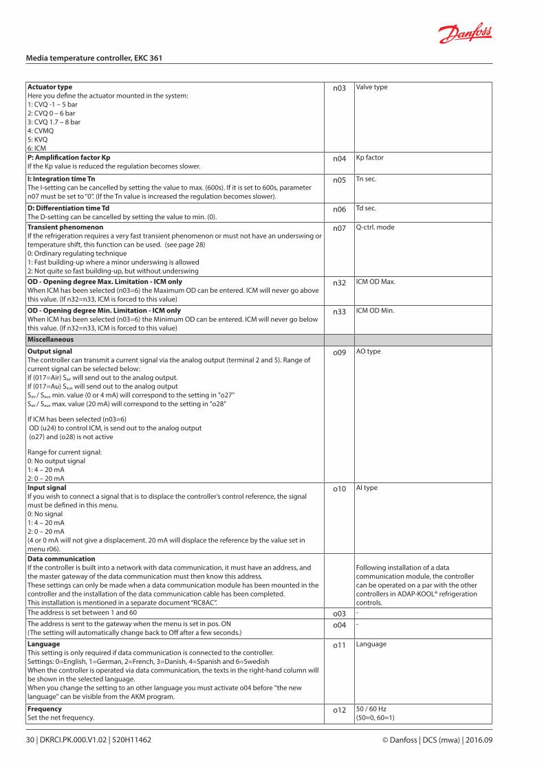
Actuator typeHere you define the actuator mounted in the system:1: CVQ -1 – 5 bar2: CVQ 0 – 6 bar3: CVQ 1.7 – 8 bar4: CVMQ5: KVQ6: ICM
n03 Valve type
P: Amplification factor KpIf the Kp value is reduced the regulation becomes slower.
n04 Kp factor
I: Integration time TnThe I-setting can be cancelled by setting the value to max. (600s). If it is set to 600s, parameter n07 must be set to “0”. (If the Tn value is increased the regulation becomes slower).
n05 Tn sec.
D: Differentiation time TdThe D-setting can be cancelled by setting the value to min. (0).
n06 Td sec.
Transient phenomenonIf the refrigeration requires a very fast transient phenomenon or must not have an underswing or temperature shift, this function can be used. (see page 28)0: Ordinary regulating technique1: Fast building-up where a minor underswing is allowed2: Not quite so fast building-up, but without underswing
n07 Q-ctrl. mode
OD - Opening degree Max. Limitation - ICM onlyWhen ICM has been selected (n03=6) the Maximum OD can be entered. ICM will never go above this value. (If n32=n33, ICM is forced to this value)
n32 ICM OD Max.
OD - Opening degree Min. Limitation - ICM onlyWhen ICM has been selected (n03=6) the Minimum OD can be entered. ICM will never go below this value. (If n32=n33, ICM is forced to this value)
n33 ICM OD Min.
Miscellaneous
Output signalThe controller can transmit a current signal via the analog output (terminal 2 and 5). Range of current signal can be selected below:If (017=Air) Sair will send out to the analog output.If (017=Au) Saux will send out to the analog outputSair / Saux min. value (0 or 4 mA) will correspond to the setting in "o27"Sair / Saux max. value (20 mA) will correspond to the setting in "o28"
If ICM has been selected (n03=6) OD (u24) to control ICM, is send out to the analog output (o27) and (o28) is not active
Range for current signal:0: No output signal1: 4 – 20 mA2: 0 – 20 mA
o09 AO type
Input signalIf you wish to connect a signal that is to displace the controller’s control reference, the signal must be defined in this menu.0: No signal1: 4 – 20 mA2: 0 – 20 mA(4 or 0 mA will not give a displacement. 20 mA will displace the reference by the value set in menu r06).
o10 AI type
Data communicationIf the controller is built into a network with data communication, it must have an address, and the master gateway of the data communication must then know this address.These settings can only be made when a data communication module has been mounted in the controller and the installation of the data communication cable has been completed.This installation is mentioned in a separate document “RC8AC”.
Following installation of a data communication module, the controller can be operated on a par with the other controllers in ADAP-KOOL® refrigeration controls.
The address is set between 1 and 60 o03 -
The address is sent to the gateway when the menu is set in pos. ON(The setting will automatically change back to Off after a few seconds.)
o04 -
LanguageThis setting is only required if data communication is connected to the controller.Settings: 0=English, 1=German, 2=French, 3=Danish, 4=Spanish and 6=SwedishWhen the controller is operated via data communication, the texts in the right-hand column will be shown in the selected language.When you change the setting to an other language you must activate o04 before "the new language" can be visible from the AKM program.
o11 Language
FrequencySet the net frequency.
o12 50 / 60 Hz(50=0, 60=1)
DKRCI.PK.000.V1.02 | 520H11462 | 31© Danfoss | DCS (mwa) | 2016.09
Media temperature controller, EKC 361
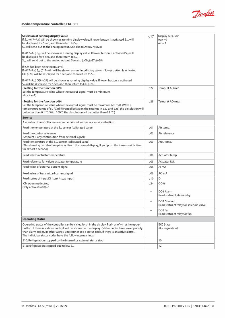
Selection of running display valueIf Sair (017=Air) will be shown as running display value. If lower button is activated Saux will be displayed for 5 sec, and then return to Sair
Sair will send out to the analog output. See also (o09),(o27),(o28)
If (017=Au) Saux will be shown as running display value. If lower button is activated Sair will be displayed for 5 sec, and then return to Saux
Saux will send out to the analog output. See also (o09),(o27),(o28)
If ICM has been selected (n03=6)If (017=Air) Sair (017=Air) will be shown as running display value. If lower button is activated OD (u24) will be displayed for 5 sec, and then return to Sair
If (017=Au) OD (u24) will be shown as running display value. If lower button is activated Sair will be displayed for 5 sec, and then return to OD (u24)
o17 Display Aux / AirAux =0Air = 1
(Setting for the function o09)Set the temperature value where the output signal must be minimum(0 or 4 mA)
o27 Temp. at AO min.
(Setting for the function o09)Set the temperature value where the output signal must be maximum (20 mA). (With a temperature range of 50 °C (differential between the settings in o27 and o28) the dissolution will be better than 0.1 °C. With 100°C the dissolution wil be better than 0.2 °C.)
o28 Temp. at AO max.
ServiceA number of controller values can be printed for use in a service situation
Read the temperature at the Sair sensor (calibrated value) u01 Air temp.
Read the control reference(Setpoint + any contribution from external signal)
u02 Air reference
Read temperature at the Saux sensor (calibrated value)(This showing can also be uploaded from the normal display, if you push the lowermost button for almost a second)
u03 Aux. temp.
Read valve’s actuator temperature u04 Actuator temp.
Read reference for valve’s actuator temperature u05 Actuator Ref.
Read value of external current signal u06 AI mA
Read value of transmitted current signal u08 AO mA
Read status of input DI (start / stop input) u10 DI
ICM opening degree.Only active if (n03)=6
u24 OD%
-- DO1 AlarmRead status of alarm relay
-- DO2 CoolingRead status of relay for solenoid valve
-- DO3 FanRead status of relay for fan
Operating status
Operating status of the controller can be called forth in the display. Push briefly (1s) the upper button. If there is a status code, it will be shown on the display. (Status codes have lower priority than alarm codes. In other words, you cannot see a status code, if there is an active alarm).The individual status codes have the following meanings:
EKC State (0 = regulation)
S10: Refrigeration stopped by the internal or external start / stop 10
S12: Refrigeration stopped due to low Sair 12
© Danfoss | DCS (mwa) | 2016.0932 | DKRCI.PK.000.V1.02 | 520H11462
Media temperature controller, EKC 361
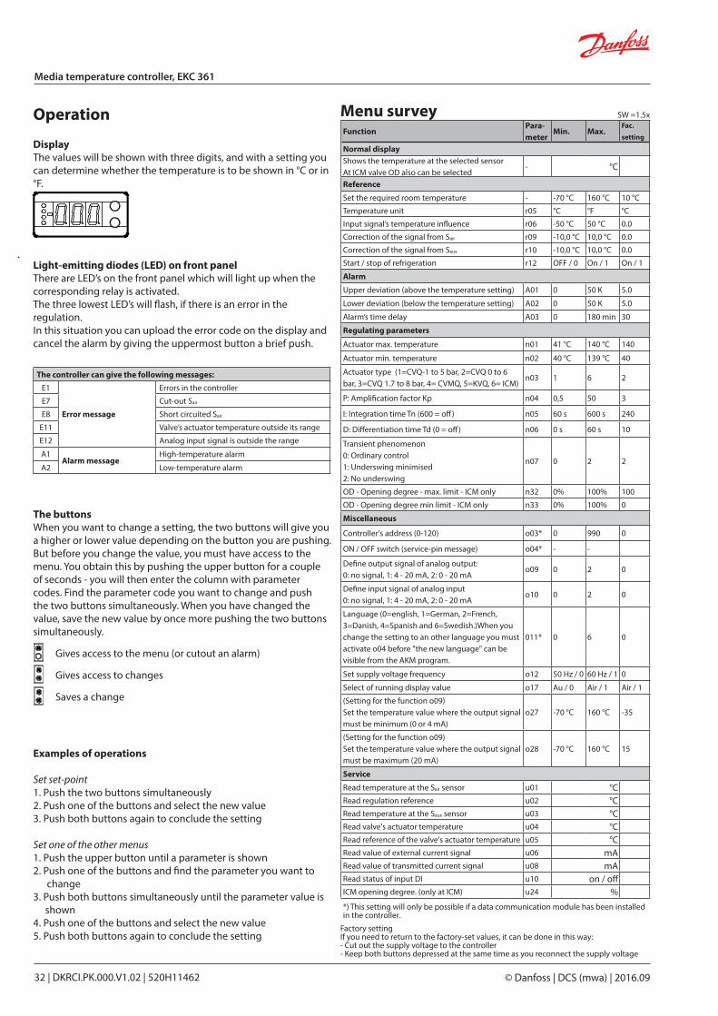
Light-emitting diodes (LED) on front panelThere are LED’s on the front panel which will light up when the corresponding relay is activated.The three lowest LED’s will flash, if there is an error in the regulation.In this situation you can upload the error code on the display and cancel the alarm by giving the uppermost button a brief push.
DisplayThe values will be shown with three digits, and with a setting you can determine whether the temperature is to be shown in °C or in °F.
Operation Menu survey
The controller can give the following messages:
E1
Error message
Errors in the controller
E7 Cut-out Sair
E8 Short circuited Sair
E11 Valve’s actuator temperature outside its range
E12 Analog input signal is outside the range
A1Alarm message
High-temperature alarm
A2 Low-temperature alarm
The buttonsWhen you want to change a setting, the two buttons will give you a higher or lower value depending on the button you are pushing. But before you change the value, you must have access to the menu. You obtain this by pushing the upper button for a couple of seconds - you will then enter the column with parameter codes. Find the parameter code you want to change and push the two buttons simultaneously. When you have changed the value, save the new value by once more pushing the two buttons simultaneously.
Gives access to the menu (or cutout an alarm)
Gives access to changes
Saves a change
Examples of operations
Set set-point1. Push the two buttons simultaneously2. Push one of the buttons and select the new value3. Push both buttons again to conclude the setting Set one of the other menus1. Push the upper button until a parameter is shown2. Push one of the buttons and find the parameter you want to
change3. Push both buttons simultaneously until the parameter value is
shown4. Push one of the buttons and select the new value5. Push both buttons again to conclude the setting
Factory settingIf you need to return to the factory-set values, it can be done in this way:- Cut out the supply voltage to the controller- Keep both buttons depressed at the same time as you recon nect the supply voltage
FunctionPara-meter
Min. Max.Fac.
setting
Normal displayShows the temperature at the selected sensorAt ICM valve OD also can be selected
- °C
Reference
Set the required room temperature - -70 °C 160 °C 10 °C
Temperature unit r05 °C °F °C
Input signal’s temperature influence r06 -50 °C 50 °C 0.0
Correction of the signal from Sair r09 -10,0 °C 10,0 °C 0.0
Correction of the signal from Saux r10 -10,0 °C 10,0 °C 0.0
Start / stop of refrigeration r12 OFF / 0 On / 1 On / 1
Alarm
Upper deviation (above the temperature setting) A01 0 50 K 5.0
Lower deviation (below the temperature setting) A02 0 50 K 5.0
Alarm’s time delay A03 0 180 min 30
Regulating parameters
Actuator max. temperature n01 41 °C 140 °C 140
Actuator min. temperature n02 40 °C 139 °C 40
Actuator type (1=CVQ-1 to 5 bar, 2=CVQ 0 to 6 bar, 3=CVQ 1.7 to 8 bar, 4= CVMQ, 5=KVQ, 6= ICM)
n03 1 6 2
P: Amplification factor Kp n04 0,5 50 3
I: Integration time Tn (600 = off) n05 60 s 600 s 240
D: Differentiation time Td (0 = off) n06 0 s 60 s 10
Transient phenomenon0: Ordinary control1: Underswing minimised2: No underswing
n07 0 2 2
OD - Opening degree - max. limit - ICM only n32 0% 100% 100
OD - Opening degree min limit - ICM only n33 0% 100% 0
Miscellaneous
Controller's address (0-120) o03* 0 990 0
ON / OFF switch (service-pin message) o04* - -
Define output signal of analog output:0: no signal, 1: 4 - 20 mA, 2: 0 - 20 mA
o09 0 2 0
Define input signal of analog input0: no signal, 1: 4 - 20 mA, 2: 0 - 20 mA
o10 0 2 0
Language (0=english, 1=German, 2=French, 3=Danish, 4=Spanish and 6=Swedish.)When you change the setting to an other language you must activate o04 before "the new language" can be visible from the AKM program.
011* 0 6 0
Set supply voltage frequency o12 50 Hz / 0 60 Hz / 1 0
Select of running display value o17 Au / 0 Air / 1 Air / 1
(Setting for the function o09)Set the temperature value where the output signal must be minimum (0 or 4 mA)
o27 -70 °C 160 °C -35
(Setting for the function o09)Set the temperature value where the output signal must be maximum (20 mA)
o28 -70 °C 160 °C 15
Service
Read temperature at the Sair sensor u01 °CRead regulation reference u02 °CRead temperature at the Saux sensor u03 °CRead valve's actuator temperature u04 °CRead reference of the valve's actuator temperature u05 °CRead value of external current signal u06 mARead value of transmitted current signal u08 mARead status of input DI u10 on / offICM opening degree. (only at ICM) u24 %*) This setting will only be possible if a data communication module has been installed in the controller.
SW =1.5x
DKRCI.PK.000.V1.02 | 520H11462 | 33© Danfoss | DCS (mwa) | 2016.09
Media temperature controller, EKC 361
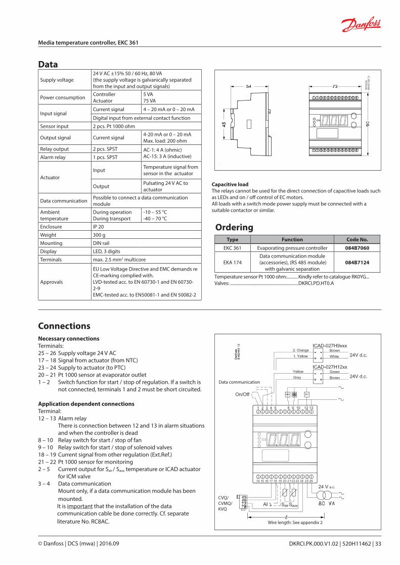
Data
OrderingType Function Code No.
EKC 361 Evaporating pressure controller 084B7060
EKA 174Data communication module
(accessories), (RS 485 module)with galvanic separation
084B7124
Necessary connectionsTerminals:25 – 26 Supply voltage 24 V AC17 – 18 Signal from actuator (from NTC)23 – 24 Supply to actuator (to PTC)20 – 21 Pt 1000 sensor at evaporator outlet1 – 2 Switch function for start / stop of regulation. If a switch is
not connected, terminals 1 and 2 must be short circuited.
Application dependent connectionsTerminal:12 – 13 Alarm relay
There is connection between 12 and 13 in alarm situa tions and when the controller is dead
8 – 10 Relay switch for start / stop of fan9 – 10 Relay switch for start / stop of solenoid valves18 – 19 Current signal from other regulation (Ext.Ref.)21 – 22 Pt 1000 sensor for monitoring2 – 5 Current output for Sair / Saux temperature or ICAD actuator for ICM valve3 – 4 Data communication Mount only, if a data communication module has been
mounted.It is important that the installation of the data communication cable be done correctly. Cf. separate literature No. RC8AC.
Connections
Supply voltage24 V AC ±15% 50 / 60 Hz, 80 VA(the supply voltage is galvanically separated from the input and output signals)
Power consumption ControllerActuator
5 VA75 VA
Input signal Current signal 4 – 20 mA or 0 – 20 mA
Digital input from external contact function
Sensor input 2 pcs. Pt 1000 ohm
Output signal Current signal 4-20 mA or 0 – 20 mAMax. load: 200 ohm
Relay output 2 pcs. SPST AC-1: 4 A (ohmic)AC-15: 3 A (inductive)Alarm relay 1 pcs. SPST
ActuatorInput Temperature signal from
sensor in the actuator
Output Pulsating 24 V AC to actuator
Data communication Possible to connect a data communication module
Ambient temperature
During operationDuring transport
-10 – 55 °C-40 – 70 °C
Enclosure IP 20
Weight 300 g
Mounting DIN rail
Display LED, 3 digits
Terminals max. 2.5 mm2 multicore
Approvals
EU Low Voltage Directive and EMC demands re CE-marking complied with.LVD-tested acc. to EN 60730-1 and EN 60730-2-9EMC-tested acc. to EN50081-1 and EN 50082-2
Temperature sensor Pt 1000 ohm: ..........Kindly refer to catalogue RK0YG...Valves: .............................................................DKRCI.PD.HT0.A
Data communication
Wire length: See appendix 2
CVQ/CVMQ/KVQ
Capacitive loadThe relays cannot be used for the direct connection of capacitive loads such as LEDs and on / off control of EC motors.All loads with a switch mode power supply must be connected with a suitable contactor or similar.
© Danfoss | DCS (mwa) | 2016.0934 | DKRCI.PK.000.V1.02 | 520H11462
Media temperature controller, EKC 361
Data communication
Examples
Example of menu display
If you want to know more about operation of controllers via PC, you may order additional literature.
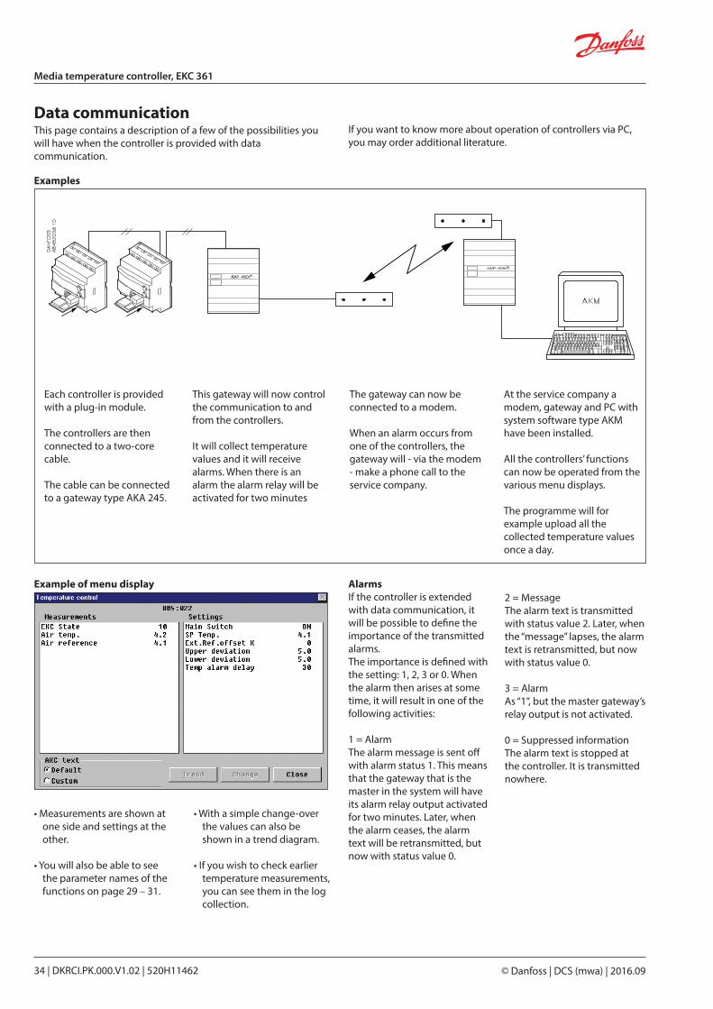
This page contains a description of a few of the possibilities you will have when the controller is provided with data communi cation.
Each controller is provided with a plug-in module.
The controllers are then connected to a two-core cable.
The cable can be connected to a gateway type AKA 245.
This gateway will now control the communication to and from the controllers.
It will collect temperature values and it will receive alarms. When there is an alarm the alarm relay will be activated for two minutes
The gateway can now be connected to a modem.
When an alarm occurs from one of the controllers, the gateway will - via the modem - make a phone call to the service company.
At the service company a modem, gateway and PC with system software type AKM have been installed.
All the controllers’ functions can now be operated from the various menu displays.
The programme will for example upload all the collected tempera ture values once a day.
• Measurements are shown at one side and settings at the other.
• You will also be able to see the parameter names of the functions on page 29 – 31.
• With a simple change-over the values can also be shown in a trend diagram.
• If you wish to check earlier temperature measurements, you can see them in the log collection.
AlarmsIf the controller is extended with data communication, it will be possible to define the importance of the transmitted alarms.The importance is defined with the setting: 1, 2, 3 or 0. When the alarm then arises at some time, it will result in one of the following activities:
1 = AlarmThe alarm message is sent off with alarm status 1. This means that the gateway that is the master in the system will have its alarm relay output activated for two minutes. Later, when the alarm ceases, the alarm text will be retransmitted, but now with status value 0.
2 = MessageThe alarm text is transmitted with status value 2. Later, when the “message” lapses, the alarm text is retransmitted, but now with status value 0.
3 = AlarmAs “1”, but the master gateway’s relay output is not activated.
0 = Suppressed informationThe alarm text is stopped at the controller. It is transmitted nowhere.
DKRCI.PK.000.V1.02 | 520H11462 | 35© Danfoss | DCS (mwa) | 2016.09
Media temperature controller, EKC 361
Appendix 1
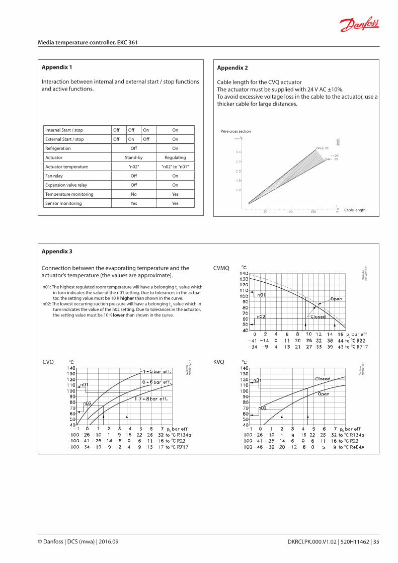
Interaction between internal and external start / stop functions and active functions.
Connection between the evaporating temperature and the actuator’s temperature (the values are approximate).
n01: The highest regulated room temperature will have a be longing to value which in turn indicates the value of the n01 setting. Due to tolerances in the actua-tor, the setting value must be 10 K higher than shown in the curve.
n02: The lowest occurring suction pressure will have a belonging to value which in turn indicates the value of the n02 setting. Due to tolerances in the actuator, the setting value must be 10 K lower than shown in the curve.
CVQ KVQ
CVMQ
Appendix 2
Cable length for the CVQ actuatorThe actuator must be supplied with 24 V AC ±10%.To avoid excessive voltage loss in the cable to the actuator, use a thicker cable for large distances.
Wire cross section
Cable length
Internal Start / stop Off Off On On
External Start / stop Off On Off On
Refrigeration Off On
Actuator Stand-by Regulating
Actuator temperature "n02" "n02" to "n01"
Fan relay Off On
Expansion valve relay Off On
Temperature monitoring No Yes
Sensor monitoring Yes Yes
Appendix 3
© Danfoss | DCS (mwa) | 2016.0936 | DKRCI.PK.000.V1.02 | 520H11462
Media temperature controller, EKC 361
Start of controller
When the electric wires have been connected to the controller, the following points have to be attended to before the regulation starts:1. Switch off the external ON / OFF switch that starts and stops the
regulation.2. Follow the menu survey on page 32, and set the various
parameters to the required values.3. Switch on the external ON / OFF switch, and regulation will
start.
If the temperature fluctuates
When the refrigerating system has been made to work steadily, the controller’s factory-set control parameters should in most cases provide a stable and relatively fast regulating system.If the system on the other hand oscillates, you must register the periods of oscillation and compare them with the set integration time Tn, and then make a couple of adjustments in the indicated parameters.
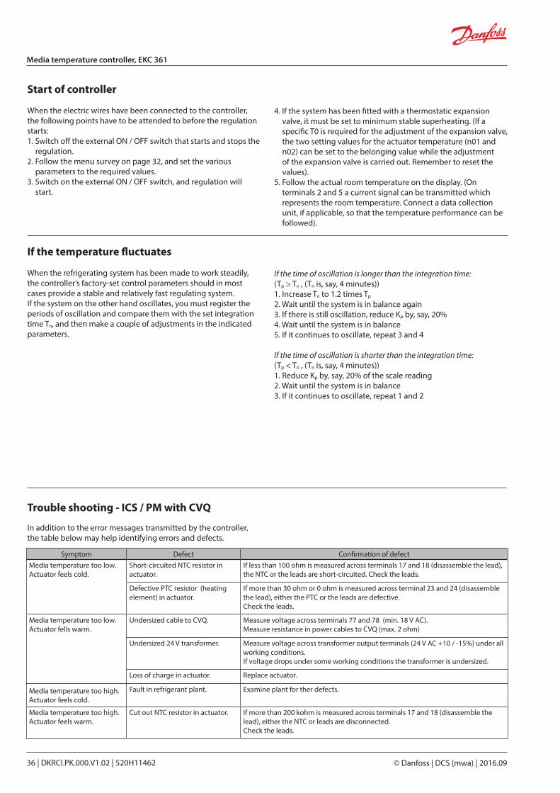
Symptom Defect Confirmation of defectMedia temperature too low.Actuator feels cold.
Short-circuited NTC resistor in actuator.
If less than 100 ohm is measured across terminals 17 and 18 (disassemble the lead), the NTC or the leads are short-circuited. Check the leads.
Defective PTC resistor (heating element) in actuator.
If more than 30 ohm or 0 ohm is measured across terminal 23 and 24 (disassemble the lead), either the PTC or the leads are defective.Check the leads.
Media temperature too low.Actuator fells warm.
Undersized cable to CVQ. Measure voltage across terminals 77 and 78 (min. 18 V AC).Measure resistance in power cables to CVQ (max. 2 ohm)
Undersized 24 V transformer. Measure voltage across transformer output terminals (24 V AC +10 / -15%) under all working conditions.If voltage drops under some working conditions the transformer is undersized.
Loss of charge in actuator. Replace actuator.
Media temperature too high. Actuator feels cold.
Fault in refrigerant plant. Examine plant for ther defects.
Media temperature too high. Actuator feels warm.
Cut out NTC resistor in actuator. If more than 200 kohm is measured across terminals 17 and 18 (disassemble the lead), either the NTC or leads are disconnected. Check the leads.
Trouble shooting - ICS / PM with CVQ
In addition to the error messages transmitted by the controller, the table below may help identifying errors and defects.
If the time of oscillation is longer than the integration time:(Tp > Tn , (Tn is, say, 4 minutes))1. Increase Tn to 1.2 times Tp
2. Wait until the system is in balance again3. If there is still oscillation, reduce Kp by, say, 20%4. Wait until the system is in balance5. If it continues to oscillate, repeat 3 and 4
If the time of oscillation is shorter than the integration time:(Tp < Tn , (Tn is, say, 4 minutes))1. Reduce Kp by, say, 20% of the scale reading2. Wait until the system is in balance3. If it continues to oscillate, repeat 1 and 2
4. If the system has been fitted with a thermostatic expansion valve, it must be set to minimum stable superheating. (If a specific T0 is required for the adjustment of the ex pansion valve, the two setting values for the actuator temperature (n01 and n02) can be set to the belonging value while the adjustment of the expansion valve is carried out. Remember to reset the values).
5. Follow the actual room temperature on the display. (On terminals 2 and 5 a current signal can be transmitted which represents the room temperature. Connect a data collection unit, if applicable, so that the temperature performance can be followed).
DKRCI.PK.000.V1.02 | 520H11462 | 37© Danfoss | DCS (mwa) | 2016.09
Media temperature controller, EKC 361
Method for fixing Kp, Tn and TdDescribed below is a method (Ziegler-Nichols) for fixing Kp, Tn and Td.1. The system is made to regulate the temperature at the required
reference with a typical load. It is important that the valve regulates, and that it is not fully open.
2. Parameter u05 is read. The actuator’s min. and max. setting is adjusted, so that the average of the min. and max. values is equal to the read u05.
3. The controller is set, so that it will regulate as a P-controller. (Td is set to 0, Tn in pos. OFF (600), and Q-Ctrl.mode is set at 0).
4. The stability of the system is examined by stopping the system for, say, one minute (using the start / stop setting or the switch). Now check how the building-up of the temperature proceeds. If the building-up peters out, raise Kp a little and repeat the start /stop operation. Continue with this until you obtain a building-up which does not peter out.
5. Kp is in this case the critical amplification (Kpcritical) and the building-up time for the continued oscillation is the critical building-up time (Tcritical).
6. Based on these values, the regulating parameters can now be calculated and subsequently set:• If PID regulation is required:
Kp < 0.6x Kpcritical Tn > 0.5x Tcritical Td < 0.12x Tcritical
• If PI regulation is required:Kp < 0.45x Kpcritical Tn > 0.85x Tcritical
7. Reset the values for the controller’s min. and max. tem peratures and Q-Ctrl.mode.
Adjustment of the actuator’s min. and max. temperaturesAt the first setting these values were set to 10 K outside of the expected temperature in order to eliminate the tolerances in the actuator. By adjusting the two values to the values where the valve is exactly in mesh, the valve will all the time remain active in its regulation.If the actuator is replaced at a later date, this procedure must be repeated for the new actuator.
Min.By adjusting the actuator’s min. temperature you obtain a limit for how low a pressure can occur in the evaporator (the point is where the valve starts a limitation of the refrigerant flow).The system must be put in an operating situation where max. capacity is called for (large refrigeration need).The min. temperature must now be changed upwards step by step, at the same time as the evaporating pressure is read on the system’s manometer.When a change of the evaporating pressure is registered, this is the point where the valve is exactly in mesh. (If frost protec tion is required for the system, the value can be raised to the belonging value).
Max.By adjusting the actuator’s max. temperature you obtain a limit for how high a pressure can occur in the evaporator (the refrigerant flow is blocked completely).The system is put in an operating situation where there is no call for refrigeration capacity (no refrigerant flow).The max. temperature is now changed downwards step by step, at the same time as the evaporating pressure is read on the system’s manometer. When a change of the evaporating pressure is registered, this is the point where the valve opens. Adjust the setting a little upwards, so that the valve will again close completely for the refrigerant flow. (If the actual application has a requirement regarding max. evaporating pressure, a lower setting may of course be selected, so that the pressure is limited).
Fine adjustments
When the system has been operating for a while, it may be required for some systems to optimise some of the adjustments. Below we have a look at settings having an influence on the speed and accuracy of the regulation.

Shut-off and regulating valves for Industrial Refrigeration
DKRCI.PK.000.V1.02 | 520H11462 | 39© Danfoss | DCS (mwa) | 2016.09
InterfaceEKC 366
Contents Page
Application. . . . . . . . . . . . . . . . . . . . . . . . . . . . . . . . . . . . . . . . . . . . . . . . . . . . . . . . . . . . . . . . . . . . . . . . . . . . . . . . . . . . . . . 41
System . . . . . . . . . . . . . . . . . . . . . . . . . . . . . . . . . . . . . . . . . . . . . . . . . . . . . . . . . . . . . . . . . . . . . . . . . . . . . . . . . . . . . . . . . . . 42
Function . . . . . . . . . . . . . . . . . . . . . . . . . . . . . . . . . . . . . . . . . . . . . . . . . . . . . . . . . . . . . . . . . . . . . . . . . . . . . . . . . . . . . . . . . 42
Survey of functions . . . . . . . . . . . . . . . . . . . . . . . . . . . . . . . . . . . . . . . . . . . . . . . . . . . . . . . . . . . . . . . . . . . . . . . . . . . . . . . 43
Operation . . . . . . . . . . . . . . . . . . . . . . . . . . . . . . . . . . . . . . . . . . . . . . . . . . . . . . . . . . . . . . . . . . . . . . . . . . . . . . . . . . . . . . . . 44
Menu survey . . . . . . . . . . . . . . . . . . . . . . . . . . . . . . . . . . . . . . . . . . . . . . . . . . . . . . . . . . . . . . . . . . . . . . . . . . . . . . . . . . . . . 44
Valve’s working temperature . . . . . . . . . . . . . . . . . . . . . . . . . . . . . . . . . . . . . . . . . . . . . . . . . . . . . . . . . . . . . . . . . . . . . . 45
Data. . . . . . . . . . . . . . . . . . . . . . . . . . . . . . . . . . . . . . . . . . . . . . . . . . . . . . . . . . . . . . . . . . . . . . . . . . . . . . . . . . . . . . . . . . . . . . 46
Connections. . . . . . . . . . . . . . . . . . . . . . . . . . . . . . . . . . . . . . . . . . . . . . . . . . . . . . . . . . . . . . . . . . . . . . . . . . . . . . . . . . . . . . 46
Ordering . . . . . . . . . . . . . . . . . . . . . . . . . . . . . . . . . . . . . . . . . . . . . . . . . . . . . . . . . . . . . . . . . . . . . . . . . . . . . . . . . . . . . . . . . 46
Data communication . . . . . . . . . . . . . . . . . . . . . . . . . . . . . . . . . . . . . . . . . . . . . . . . . . . . . . . . . . . . . . . . . . . . . . . . . . . . . 47
DKRCI.PS.RP0.C1.02 | 2015.11

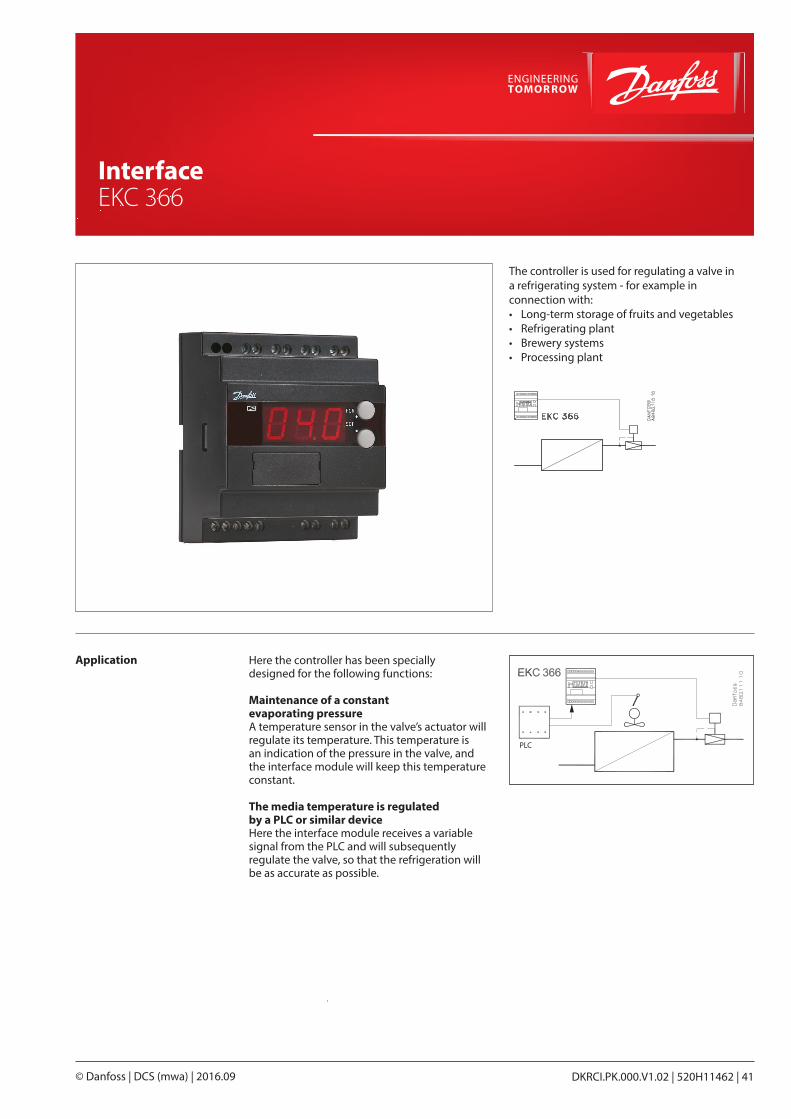
Shut-off and regulating valves for Industrial Refrigeration
DKRCI.PK.000.V1.02 | 520H11462 | 41© Danfoss | DCS (mwa) | 2016.09
InterfaceEKC 366
Application Here the controller has been specially designed for the following functions:
Maintenance of a constant evaporating pressureA temperature sensor in the valve’s actuator will regulate its temperature. This temperature is an indication of the pressure in the valve, and the interface module will keep this temperature constant.
The media temperature is regulated by a PLC or similar deviceHere the interface module receives a variable signal from the PLC and will subsequently regulate the valve, so that the refrigeration will be as accurate as possible.
The controller is used for regulating a valve in a refrigerating system - for example in connection with:• Long-term storage of fruits and vegetables• Refrigerating plant• Brewery systems• Processing plant
PLC
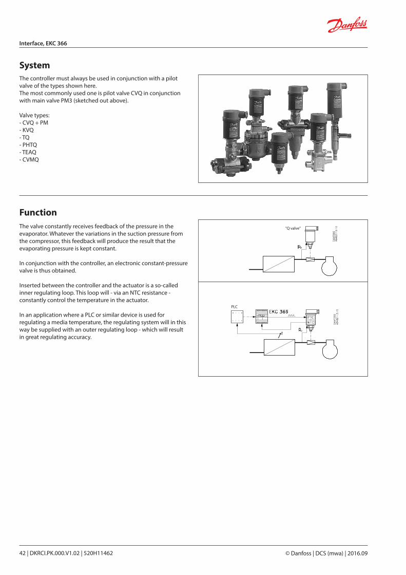
© Danfoss | DCS (mwa) | 2016.0942 | DKRCI.PK.000.V1.02 | 520H11462
Interface, EKC 366
The controller must always be used in conjunction with a pilot valve of the types shown here.The most commonly used one is pilot valve CVQ in conjunction with main valve PM3 (sketched out above).
Valve types:- CVQ + PM- KVQ- TQ- PHTQ- TEAQ- CVMQ
FunctionThe valve constantly receives feedback of the pressure in the evaporator. Whatever the variations in the suction pressure from the compressor, this feedback will produce the result that the evaporating pressure is kept constant.
In conjunction with the controller, an electronic constant-pressure valve is thus obtained.
Inserted between the controller and the actuator is a so-called inner regulating loop. This loop will - via an NTC resistance - constantly control the temperature in the actuator.
In an application where a PLC or similar device is used for regulating a media temperature, the regulating system will in this way be supplied with an outer regulating loop - which will result in great regulating accuracy.
System
"Q valve"
PLC
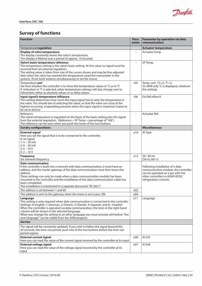
DKRCI.PK.000.V1.02 | 520H11462 | 43© Danfoss | DCS (mwa) | 2016.09
Interface, EKC 366
Survey of functionsFunction Para-
meterParameter by operation via data communication
Temperature regulation Actuator temperature Display of valve temperatureThe display constantly shows the valve's temperature.The display is filtered over a period of approx. 10 seconds
– Actuator temp.
Valve’s basic temperature referenceThis temperature setting is the valve’s basic setting. At this value no signal must be received from an external regulation. The setting value is taken from one of the curves shown and may be fine-adjusted later when the valve has reached the temperature (read the manometer in the system). (Push both buttons simultaneously to set the menu)
– SP Temp.
Temperature unitSet here whether the controller is to show the temperature values in °C or in °F. If indication in °F is selected, other temperature settings will also change over to Fahrenheit, either as absolute values or as delta values.
r05 Temp. unit (°C=0, °F=1)(In AKM only °C is displayed, whatever the setting).
Input signal’s temperature influenceThis setting determines how much the input signal has to raise the temperature in the valve. You should aim at selecting the value, so that the valve can close at the highest occurring evaporating pressure when the input signal is maximum (value to be set in Kelvin)
r06 Ext.Ref.offset K
ReferenceThe valve’s temperature is regulated on the basis of the basic setting plus the signal from the external regulation. (Reference = SP Temp + percentage of "r06".)The reference can be seen when you push the lower of the two buttons
– Actuator Ref.
Sundry configurations Miscellaneous
External signalHere you set the signal that is to be connected to the controller.0: no signal1: 4 – 20 mA2: 0 – 20 mA3: 0 – 10 V4: 2 – 10 V
o10 AI Type
FrequencySet network frequency
o12 50 / 60 Hz (50=0, 60=1)
Data communicationIf the controller is built into a network with data communication, it must have an address, and the master gateway of the data communication must then know this address.These settings can only be made when a data communication module has been mounted in the controller and the installation of the data communication cable has been completed.This installation is mentioned in a separate document “RC.8A.C”.
Following installation of a data communication module, the controller can be operated on a par with the other controllers in ADAP-KOOL® refrigeration controls.
The address is set between 1 and 60 o03The address is sent to the gateway when the menu is set in pos. ON o04LanguageThis setting is only required when data communication is connected to the controller.Settings: 0=English, 1=German, 2=French, 3=Danish, 4=Spanish, and 6= SwedishWhen the controller is operated via data communication, the texts in the right-hand column will be shown in the selected language.When you change the setting to an other language you must activate o04 before "the new language" can be visible from the AKM program.
o11 Language
Service
The signal will be constantly updated. If you wish to follow the signal beyond the 20 seconds, the time-out period, push one of the two buttons before the time-out period expiresExternal current signalHere you can read the value of the current signal received by the controller at its input
u06 AI mA
External voltage signalHere you can read the value of the voltage signal received by the controller at its input
u07 AI Volt
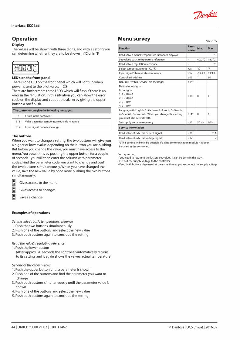
© Danfoss | DCS (mwa) | 2016.0944 | DKRCI.PK.000.V1.02 | 520H11462
Interface, EKC 366
The buttonsWhen you want to change a setting, the two buttons will give you a higher or lower value depending on the button you are pushing. But before you change the value, you must have access to the menu. You obtain this by pushing the upper button for a couple of seconds - you will then enter the column with parameter codes. Find the parameter code you want to change and push the two buttons simultaneously. When you have changed the value, save the new value by once more pushing the two buttons simultaneously.
Gives access to the menu
Gives access to changes
Saves a change
LED’s on the front panelThere is one LED on the front panel which will light up when power is sent to the pilot valve.There are furthermore three LED’s which will flash if there is anerror in the regulation. In this situation you can show the error code on the display and cut out the alarm by giving the upper button a brief push.
DisplayThe values will be shown with three digits, and with a setting you can determine whether they are to be shown in °C or in °F.
Operation
Examples of operations
Set the valve’s basic temperature reference1. Push the two buttons simultaneously2. Push one of the buttons and select the new value3. Push both buttons again to conclude the setting Read the valve’s regulating reference1. Push the lower button
(After approx. 20 seconds the controller automatically returns to its setting, and it again shows the valve’s actual temperature)
Set one of the other menus1. Push the upper button until a parameter is shown2. Push one of the buttons and find the parameter you want to
change3. Push both buttons simultaneously until the parameter value is
shown4. Push one of the buttons and select the new value5. Push both buttons again to conclude the setting
Menu survey
FunctionPara-meter
Min. Max.
Read valve’s actual temperature (standard display) - °CSet valve’s basic temperature reference - 40.0 °C 140 °C
Read valve’s regulation reference - °CSelect temperature unit (°C / °F) r05 °C °F
Input signal’s temperature influence r06 -99.9 K 99.9 K
Controller’s address o03* 1 60
ON / OFF switch (service-pin message) o04* - -
Define input signal0: no signal1: 4 – 20 mA2: 0 – 20 mA3: 0 – 10 V4: 2 – 10 V
o10 0 4
Language (0=English, 1=German, 2=french, 3=Danish, 4=Spanish, 6=Swedish). When you change this setting you must also activate o04.
011* 0 6
Set supply voltage frequency o12 50 Hz 60 Hz
Service information
Read value of external current signal u06 mARead value of external voltage signal u07 V*) This setting will only be possible if a data communication module has been installed in the controller.
The controller can give the following messages:
E1 Errors in the controller
E11 Valve’s actuator temperature outside its range
E12 Input signal outside its range
Factory settingIf you need to return to the factory-set values, it can be done in this way:- Cut out the supply voltage to the controller- Keep both buttons depressed at the same time as you recon nect the supply voltage
SW =1.2x
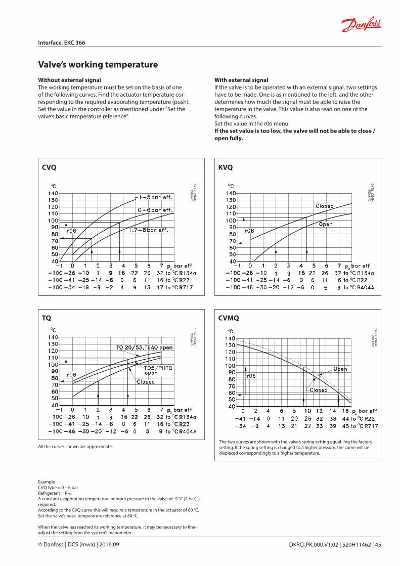
DKRCI.PK.000.V1.02 | 520H11462 | 45© Danfoss | DCS (mwa) | 2016.09
Interface, EKC 366
Valve’s working temperatureWith external signalIf the valve is to be operated with an external signal, two settings have to be made. One is as mentioned to the left, and the other determines how much the signal must be able to raise the temperature in the valve. This value is also read on one of the following curves.Set the value in the r06 menu.If the set value is too low, the valve will not be able to close /open fully.
CVQ KVQ
TQ
Without external signalThe working temperature must be set on the basis of one of the following curves. Find the actuator temperature cor-responding to the required evaporating temperature (push). Set the value in the controller as mentioned under “Set the valve’s basic temperature reference”.
The two curves are shown with the valve’s spring setting equal-ling the factory setting. If the spring setting is changed to a higher pressure, the curve will be displaced correspondingly to a higher temperature.
CVMQ
ExampleCVQ type = 0 – 6 barRefrigerant = R717
A constant evaporating temperature or input pressure to the valve of -9 °C (2 bar) is required.According to the CVQ curve this will require a temperature in the actuator of 80 °C. Set the valve’s basic temperature reference at 80 °C.
When the valve has reached its working temperature, it may be necessary to fine-adjust the setting from the system’s manometer.
All the curves shown are approximate.
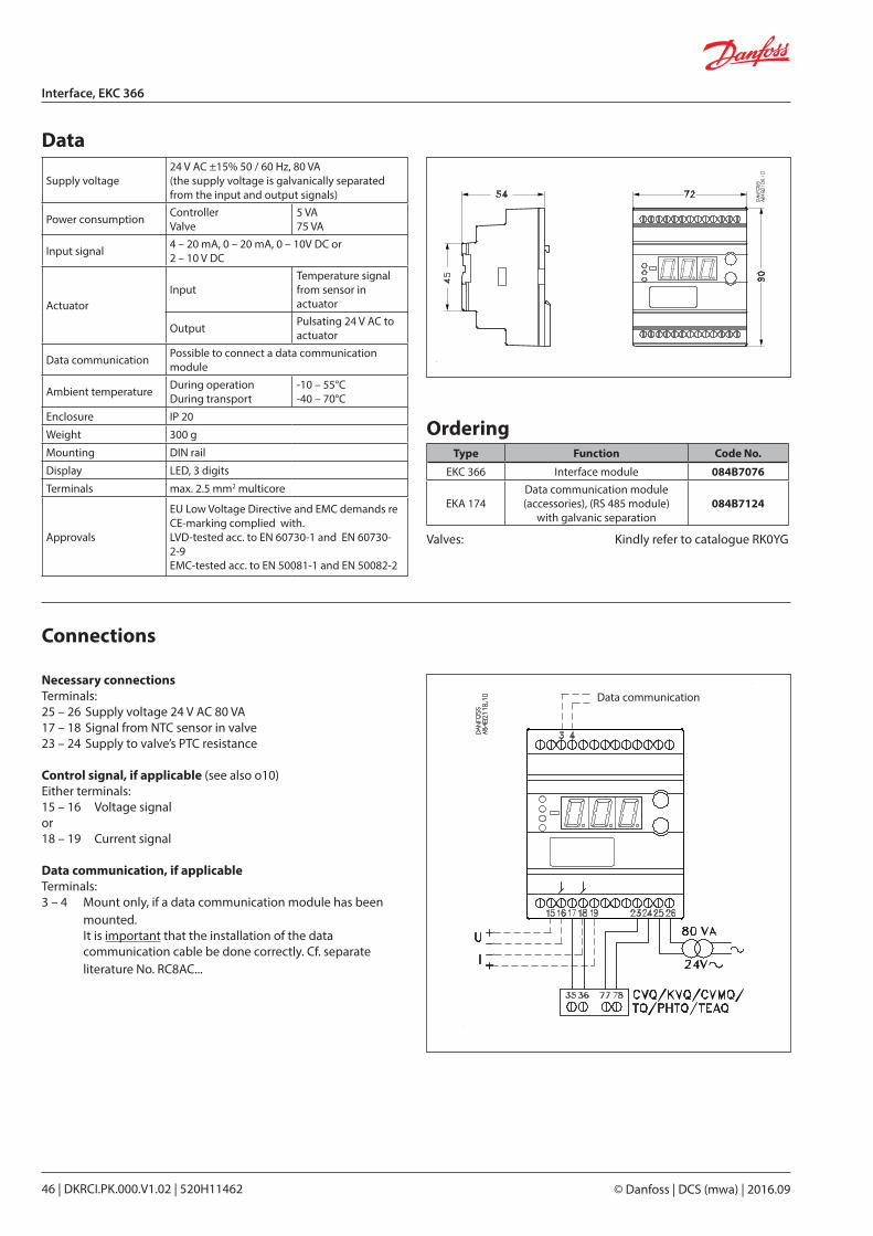
© Danfoss | DCS (mwa) | 2016.0946 | DKRCI.PK.000.V1.02 | 520H11462
Interface, EKC 366
Data
OrderingType Function Code No.
EKC 366 Interface module 084B7076
EKA 174Data communication module (accessories), (RS 485 module)
with galvanic separation084B7124
Necessary connectionsTerminals:25 – 26 Supply voltage 24 V AC 80 VA17 – 18 Signal from NTC sensor in valve23 – 24 Supply to valve’s PTC resistance
Control signal, if applicable (see also o10)Either terminals:15 – 16 Voltage signalor18 – 19 Current signal
Data communication, if applicableTerminals:3 – 4 Mount only, if a data communication module has been
mounted.It is important that the installation of the data communication cable be done correctly. Cf. separate literature No. RC8AC...
Connections
Supply voltage24 V AC ±15% 50 / 60 Hz, 80 VA(the supply voltage is galvanically separated from the input and output signals)
Power consumption ControllerValve
5 VA75 VA
Input signal 4 – 20 mA, 0 – 20 mA, 0 – 10V DC or2 – 10 V DC
ActuatorInput
Temperature signal from sensor in actuator
Output Pulsating 24 V AC to actuator
Data communication Possible to connect a data communication module
Ambient temperature During operationDuring transport
-10 – 55°C-40 – 70°C
Enclosure IP 20
Weight 300 g
Mounting DIN rail
Display LED, 3 digits
Terminals max. 2.5 mm2 multicore
Approvals
EU Low Voltage Directive and EMC demands re CE-marking complied with.LVD-tested acc. to EN 60730-1 and EN 60730-2-9EMC-tested acc. to EN 50081-1 and EN 50082-2
Data communication
Valves: Kindly refer to catalogue RK0YG
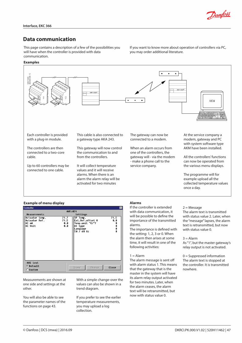
DKRCI.PK.000.V1.02 | 520H11462 | 47© Danfoss | DCS (mwa) | 2016.09
Interface, EKC 366
Data communication
Examples
Example of menu display
If you want to know more about operation of controllers via PC, you may order additional literature.
This page contains a description of a few of the possibilities you will have when the controller is provided with data communi cation.
Each controller is provided with a plug-in module.
The controllers are then connected to a two-core cable.
Up to 60 controllers may be connected to one cable.
This cable is also connected to a gateway type AKA 243.
This gateway will now control the communication to and from the controllers.
It will collect temperature values and it will receive alarms. When there is an alarm the alarm relay will be activated for two minutes
The gateway can now be connected to a modem.
When an alarm occurs from one of the controllers, the gateway will - via the modem - make a phone call to the service company.
At the service company a modem, gateway and PC with system software type AKM have been installed.
All the controllers’ functions can now be operated from the various menu displays.
The programme will for example upload all the collected tempera ture values once a day.
With a simple change-over the values can also be shown in a trend diagram.
If you prefer to see the earlier temperature measurements, you may upload a log collection.
AlarmsIf the controller is extended with data communication, it will be possible to define the importance of the transmitted alarms.The importance is defined with the setting: 1, 2, 3 or 0. When the alarm then arises at some time, it will result in one of the following activities:
1 = AlarmThe alarm message is sent off with alarm status 1. This means that the gateway that is the master in the system will have its alarm relay output activated for two minutes. Later, when the alarm ceases, the alarm text will be retransmitted, but now with status value 0.
Measurements are shown at one side and settings at the other.
You will also be able to see the parameter names of the functions on page 43.
2 = MessageThe alarm text is transmitted with status value 2. Later, when the “message” lapses, the alarm text is retransmitted, but now with status value 0.
3 = AlarmAs “1”, but the master gateway’s relay output is not activated.
0 = Suppressed informationThe alarm text is stopped at the controller. It is transmitted nowhere.

Shut-off and regulating valves for Industrial Refrigeration
DKRCI.PK.000.V1.02 | 520H11462 | 49© Danfoss | DCS (mwa) | 2016.09
Superheat controller EKC 315A
DKRCI.PS.RP0.D2.02 | 2015.03
Contents Page
Advantages . . . . . . . . . . . . . . . . . . . . . . . . . . . . . . . . . . . . . . . . . . . . . . . . . . . . . . . . . . . . . . . . . . . . . . . . . . . . . . . . . . . . . . 51
Introduction. . . . . . . . . . . . . . . . . . . . . . . . . . . . . . . . . . . . . . . . . . . . . . . . . . . . . . . . . . . . . . . . . . . . . . . . . . . . . . . . . . . . . . 52
Operation . . . . . . . . . . . . . . . . . . . . . . . . . . . . . . . . . . . . . . . . . . . . . . . . . . . . . . . . . . . . . . . . . . . . . . . . . . . . . . . . . . . . . . . . 53
Survey of functions . . . . . . . . . . . . . . . . . . . . . . . . . . . . . . . . . . . . . . . . . . . . . . . . . . . . . . . . . . . . . . . . . . . . . . . . . . . . . . . 54
Operation . . . . . . . . . . . . . . . . . . . . . . . . . . . . . . . . . . . . . . . . . . . . . . . . . . . . . . . . . . . . . . . . . . . . . . . . . . . . . . . . . . . . . . . . 58
Menu survey . . . . . . . . . . . . . . . . . . . . . . . . . . . . . . . . . . . . . . . . . . . . . . . . . . . . . . . . . . . . . . . . . . . . . . . . . . . . . . . . . . . . . 58
Data. . . . . . . . . . . . . . . . . . . . . . . . . . . . . . . . . . . . . . . . . . . . . . . . . . . . . . . . . . . . . . . . . . . . . . . . . . . . . . . . . . . . . . . . . . . . . . 60
Connections. . . . . . . . . . . . . . . . . . . . . . . . . . . . . . . . . . . . . . . . . . . . . . . . . . . . . . . . . . . . . . . . . . . . . . . . . . . . . . . . . . . . . . 60
Ordering . . . . . . . . . . . . . . . . . . . . . . . . . . . . . . . . . . . . . . . . . . . . . . . . . . . . . . . . . . . . . . . . . . . . . . . . . . . . . . . . . . . . . . . . . 60
Installation considerations. . . . . . . . . . . . . . . . . . . . . . . . . . . . . . . . . . . . . . . . . . . . . . . . . . . . . . . . . . . . . . . . . . . . . . . . 61
Start of controller . . . . . . . . . . . . . . . . . . . . . . . . . . . . . . . . . . . . . . . . . . . . . . . . . . . . . . . . . . . . . . . . . . . . . . . . . . . . . . . . . 63
If the superheating fluctuates . . . . . . . . . . . . . . . . . . . . . . . . . . . . . . . . . . . . . . . . . . . . . . . . . . . . . . . . . . . . . . . . . . . . . 63
If the superheat has excessive underswing during start-up . . . . . . . . . . . . . . . . . . . . . . . . . . . . . . . . . . . . . . . . . 63

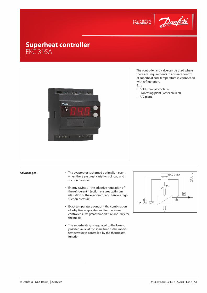
Shut-off and regulating valves for Industrial Refrigeration
DKRCI.PK.000.V1.02 | 520H11462 | 51© Danfoss | DCS (mwa) | 2016.09
Superheat controller EKC 315A
Advantages • The evaporator is charged optimally – even when there are great variations of load and suction pressure
• Energy savings – the adaptive regulation of the refrigerant injection ensures optimum utilisation of the evaporator and hence a high suction pressure
• Exact temperature control – the combination of adaptive evaporator and temperature control ensures great temperature accuracy for the media
• The superheating is regulated to the lowest possible value at the same time as the media temperature is controlled by the thermostat function
The controller and valve can be used where there are requirements to accurate control of superheat and temperature in connection with refrigeration.E.g.:• Cold store (air coolers)• Processing plant (water chillers)• A/C plant
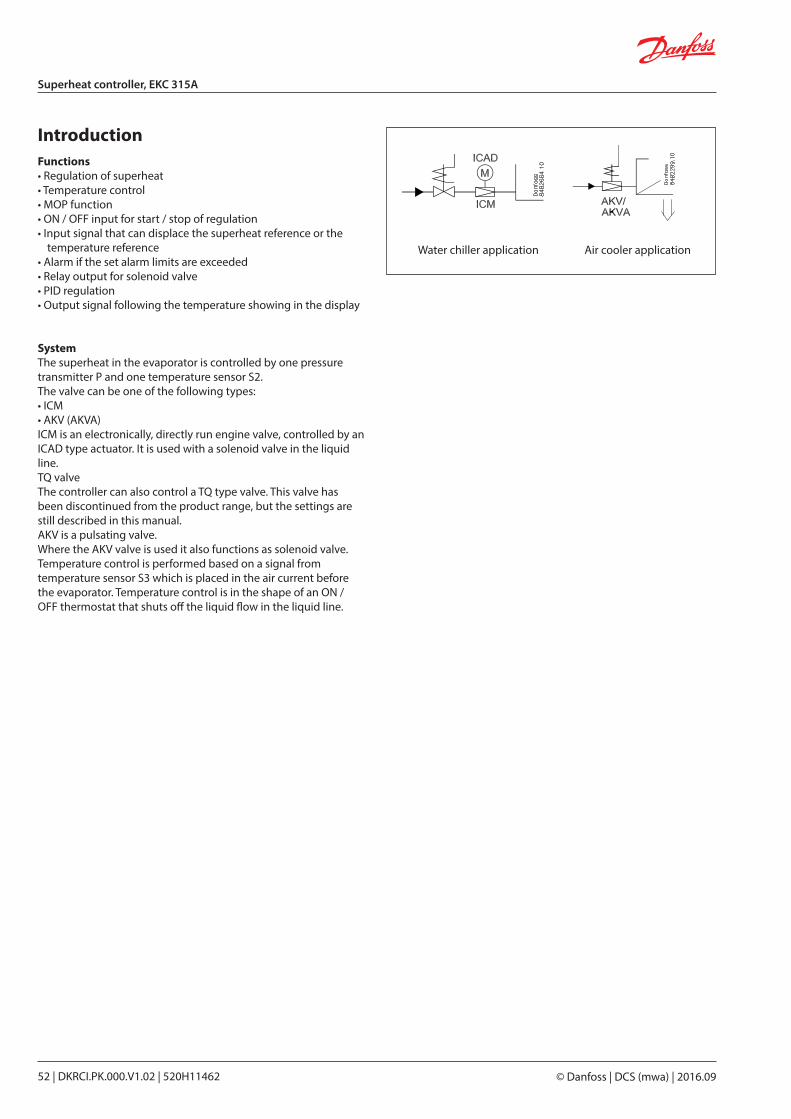
© Danfoss | DCS (mwa) | 2016.0952 | DKRCI.PK.000.V1.02 | 520H11462
Superheat controller, EKC 315A
IntroductionFunctions• Regulation of superheat• Temperature control• MOP function• ON / OFF input for start / stop of regulation• Input signal that can displace the superheat reference or the
temperature reference• Alarm if the set alarm limits are exceeded• Relay output for solenoid valve• PID regulation• Output signal following the temperature showing in the display
SystemThe superheat in the evaporator is controlled by one pressure transmitter P and one temperature sensor S2.The valve can be one of the following types:• ICM• AKV (AKVA)ICM is an electronically, directly run engine valve, controlled by an ICAD type actuator. It is used with a solenoid valve in the liquid line.TQ valveThe controller can also control a TQ type valve. This valve has been discontinued from the product range, but the settings are still described in this manual.AKV is a pulsating valve.Where the AKV valve is used it also functions as solenoid valve.Temperature control is performed based on a signal from temperature sensor S3 which is placed in the air current before the evaporator. Temperature control is in the shape of an ON / OFF thermostat that shuts off the liquid flow in the liquid line.
Water chiller application Air cooler application
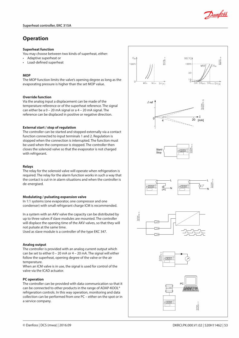
DKRCI.PK.000.V1.02 | 520H11462 | 53© Danfoss | DCS (mwa) | 2016.09
Superheat controller, EKC 315A
Operation
Superheat functionYou may choose between two kinds of superheat, either:• Adaptive superheat or• Load-defined superheat
MOPThe MOP function limits the valve’s opening degree as long as the evaporating pressure is higher than the set MOP value.
Override functionVia the analog input a displacement can be made of the temperature reference or of the superheat reference. The signal can either be a 0 – 20 mA signal or a 4 – 20 mA signal. The reference can be displaced in positive or negative direction.
External start / stop of regulationThe controller can be started and stopped externally via a contact function connected to input terminals 1 and 2. Regulation is stopped when the connection is interrupted. The function must be used when the compressor is stopped. The controller then closes the solenoid valve so that the evaporator is not charged with refrigerant.
RelaysThe relay for the solenoid valve will operate when refrigeration is required. The relay for the alarm function works in such a way that the contact is cut-in in alarm situations and when the controller is de-energised.
Modulating / pulsating expansion valveIn 1:1 systems (one evaporator, one compressor and one condenser) with small refrigerant charge ICM is recommended.
In a system with an AKV valve the capacity can be distributed by up to three valves if slave modules are mounted. The controller will displace the opening time of the AKV valves, so that they will not pulsate at the same time.Used as slave module is a controller of the type EKC 347.
Analog outputThe controller is provided with an analog current output which can be set to either 0 – 20 mA or 4 – 20 mA. The signal will either follow the superheat, opening degree of the valve or the air temperature.When an ICM valve is in use, the signal is used for control of the valve via the ICAD actuator.
PC operationThe controller can be provided with data communication so that it can be connected to other products in the range of ADAP-KOOL® refrigeration controls. In this way operation, monitoring and data collection can be performed from one PC – either on the spot or in a service company.
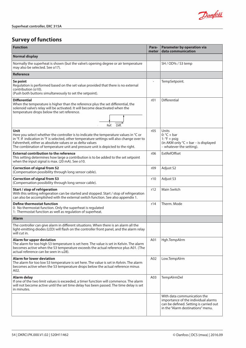
© Danfoss | DCS (mwa) | 2016.0954 | DKRCI.PK.000.V1.02 | 520H11462
Superheat controller, EKC 315A
Ref. Diff.
Function Para- meter
Parameter by operation via data communication
Normal display
Normally the superheat is shown (but the valve’s opening degree or air temperature may also be selected. See o17).
SH / OD% / S3 temp
Reference
Se pointRegulation is performed based on the set value provided that there is no external contribution (o10).(Push both buttons simultaneously to set the setpoint).
- TempSetpoint.
DifferentialWhen the temperature is higher than the reference plus the set differential, the solenoid valve’s relay will be activated. It will become deactivated when the temperature drops below the set reference.
r01 Differential
UnitHere you select whether the controller is to indicate the temperature values in °C or in °F. If indication in °F is selected, other temperature settings will also change over to Fahrenheit, either as absolute values or as delta valuesThe combination of temperature unit and pressure unit is depicted to the right.
r05 Units0: °C + bar1: °F + psig(in AKM only °C + bar – is displayed – whatever the setting).
External contribution to the reference This setting determines how large a contribution is to be added to the set setpoint when the input signal is max. (20 mA). See o10.
r06 ExtRefOffset
Correction of signal from S2(Compensation possibility through long sensor cable).
r09 Adjust S2
Correction of signal from S3(Compensation possibility through long sensor cable).
r10 Adjust S3
Start / stop of refrigerationWith this setting refrigeration can be started and stopped. Start / stop of refrigeration can also be accomplished with the external switch function. See also appendix 1.
r12 Main Switch
Define thermostat function0: No thermostat function. Only the superheat is regulated1: Thermostat function as well as regulation of superheat.
r14 Therm. Mode
Alarm
The controller can give alarm in different situations. When there is an alarm all the light-emitting diodes (LED) will flash on the controller front panel, and the alarm relay will cut in.
Alarm for upper deviationThe alarm for too high S3 temperature is set here. The value is set in Kelvin. The alarm becomes active when the S3 temperature exceeds the actual reference plus A01. (The actual reference can be seen in u28).
A01 Hgh.TempAlrm
Alarm for lower deviationThe alarm for too low S3 temperature is set here. The value is set in Kelvin. The alarm becomes active when the S3 temperature drops below the actual reference minus A02.
A02 Low.TempAlrm
Alarm delayIf one of the two limit values is exceeded, a timer function will commence. The alarm will not become active until the set time delay has been passed. The time delay is set in minutes.
A03 TempAlrmDel
With data communication the importance of the individual alarms can be defined. Setting is carried out in the “Alarm destinations” menu.
Survey of functions
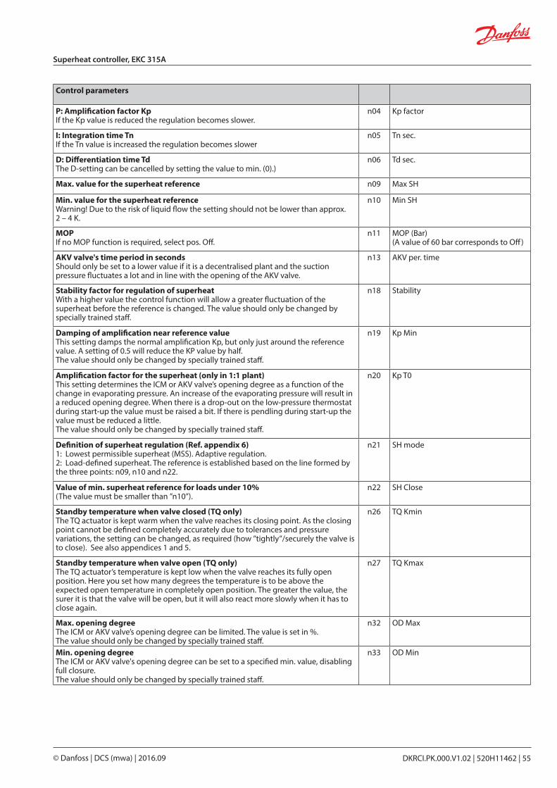
DKRCI.PK.000.V1.02 | 520H11462 | 55© Danfoss | DCS (mwa) | 2016.09
Superheat controller, EKC 315A
Control parameters
P: Amplification factor KpIf the Kp value is reduced the regulation becomes slower.
n04 Kp factor
I: Integration time TnIf the Tn value is increased the regulation becomes slower
n05 Tn sec.
D: Differentiation time TdThe D-setting can be cancelled by setting the value to min. (0).)
n06 Td sec.
Max. value for the superheat reference n09 Max SH
Min. value for the superheat referenceWarning! Due to the risk of liquid flow the setting should not be lower than approx. 2 – 4 K.
n10 Min SH
MOPIf no MOP function is required, select pos. Off.
n11 MOP (Bar)(A value of 60 bar corresponds to Off)
AKV valve's time period in secondsShould only be set to a lower value if it is a decentralised plant and the suction pressure fluctuates a lot and in line with the opening of the AKV valve.
n13 AKV per. time
Stability factor for regulation of superheatWith a higher value the control function will allow a greater fluctuation of the superheat before the reference is changed. The value should only be changed by specially trained staff.
n18 Stability
Damping of amplification near reference valueThis setting damps the normal amplification Kp, but only just around the reference value. A setting of 0.5 will reduce the KP value by half.The value should only be changed by specially trained staff.
n19 Kp Min
Amplification factor for the superheat (only in 1:1 plant)This setting determines the ICM or AKV valve’s opening degree as a function of the change in evaporating pressure. An increase of the evaporating pressure will result in a reduced opening degree. When there is a drop-out on the low-pressure thermostat during start-up the value must be raised a bit. If there is pendling during start-up the value must be reduced a little.The value should only be changed by specially trained staff.
n20 Kp T0
Definition of superheat regulation (Ref. appendix 6)1: Lowest permissible superheat (MSS). Adaptive regulation.2: Load-defined superheat. The reference is established based on the line formed by the three points: n09, n10 and n22.
n21 SH mode
Value of min. superheat reference for loads under 10%(The value must be smaller than ”n10”).
n22 SH Close
Standby temperature when valve closed (TQ only)The TQ actuator is kept warm when the valve reaches its closing point. As the closing point cannot be defined completely accurately due to tolerances and pressure variations, the setting can be changed, as required (how ”tightly”/securely the valve is to close). See also appendices 1 and 5.
n26 TQ Kmin
Standby temperature when valve open (TQ only)The TQ actuator’s temperature is kept low when the valve reaches its fully open position. Here you set how many degrees the temperature is to be above the expected open temperature in completely open position. The greater the value, the surer it is that the valve will be open, but it will also react more slowly when it has to close again.
n27 TQ Kmax
Max. opening degreeThe ICM or AKV valve’s opening degree can be limited. The value is set in %.The value should only be changed by specially trained staff.
n32 OD Max
Min. opening degreeThe ICM or AKV valve's opening degree can be set to a specified min. value, disabling full closure.The value should only be changed by specially trained staff.
n33 OD Min
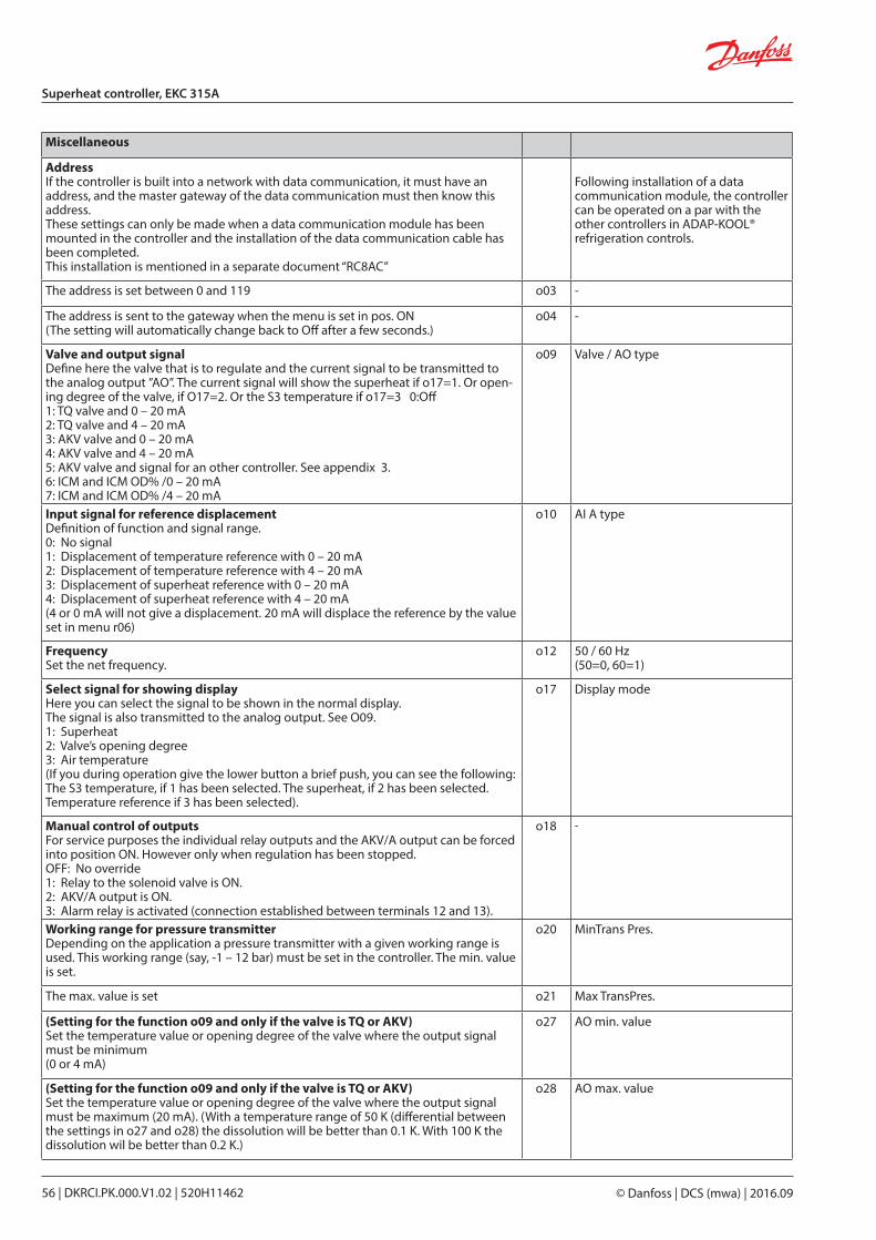
© Danfoss | DCS (mwa) | 2016.0956 | DKRCI.PK.000.V1.02 | 520H11462
Superheat controller, EKC 315A
Miscellaneous
AddressIf the controller is built into a network with data communication, it must have an address, and the master gateway of the data communication must then know this address.These settings can only be made when a data communication module has been mounted in the controller and the installation of the data communication cable has been completed.This installation is mentioned in a separate document “RC8AC”
Following installation of a data communication module, the controller can be operated on a par with the other controllers in ADAP-KOOL® refrigeration controls.
The address is set between 0 and 119 o03 -
The address is sent to the gateway when the menu is set in pos. ON(The setting will automatically change back to Off after a few seconds.)
o04 -
Valve and output signalDefine here the valve that is to regulate and the current signal to be transmitted to the analog output ”AO”. The current signal will show the superheat if o17=1. Or open-ing degree of the valve, if O17=2. Or the S3 temperature if o17=3 0:Off1: TQ valve and 0 – 20 mA2: TQ valve and 4 – 20 mA3: AKV valve and 0 – 20 mA4: AKV valve and 4 – 20 mA5: AKV valve and signal for an other controller. See appendix 3.6: ICM and ICM OD% /0 – 20 mA7: ICM and ICM OD% /4 – 20 mA
o09 Valve / AO type
Input signal for reference displacementDefinition of function and signal range.0: No signal1: Displacement of temperature reference with 0 – 20 mA2: Displacement of temperature reference with 4 – 20 mA3: Displacement of superheat reference with 0 – 20 mA4: Displacement of superheat reference with 4 – 20 mA(4 or 0 mA will not give a displacement. 20 mA will displace the reference by the value set in menu r06)
o10 AI A type
FrequencySet the net frequency.
o12 50 / 60 Hz(50=0, 60=1)
Select signal for showing displayHere you can select the signal to be shown in the normal display.The signal is also transmitted to the analog output. See O09.1: Superheat2: Valve’s opening degree3: Air temperature(If you during operation give the lower button a brief push, you can see the following: The S3 temperature, if 1 has been selected. The superheat, if 2 has been selected. Temperature reference if 3 has been selected).
o17 Display mode
Manual control of outputsFor service purposes the individual relay outputs and the AKV/A output can be forced into position ON. However only when regulation has been stopped.OFF: No override1: Relay to the solenoid valve is ON.2: AKV/A output is ON.3: Alarm relay is activated (connection established between terminals 12 and 13).
o18 -
Working range for pressure transmitterDepending on the application a pressure transmitter with a given working range is used. This working range (say, -1 – 12 bar) must be set in the controller. The min. value is set.
o20 MinTrans Pres.
The max. value is set o21 Max TransPres.
(Setting for the function o09 and only if the valve is TQ or AKV)Set the temperature value or opening degree of the valve where the output signal must be minimum(0 or 4 mA)
o27 AO min. value
(Setting for the function o09 and only if the valve is TQ or AKV)Set the temperature value or opening degree of the valve where the output signal must be maximum (20 mA). (With a temperature range of 50 K (differential between the settings in o27 and o28) the dissolution will be better than 0.1 K. With 100 K the dissolution wil be better than 0.2 K.)
o28 AO max. value
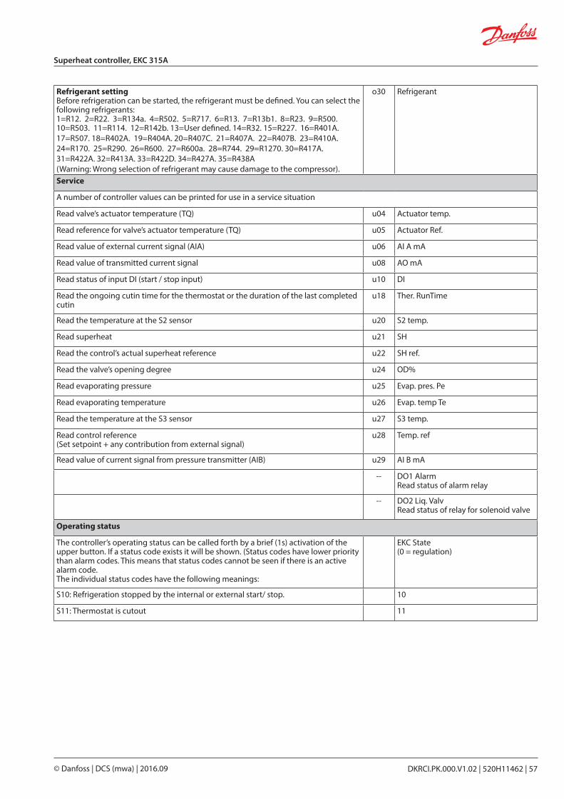
DKRCI.PK.000.V1.02 | 520H11462 | 57© Danfoss | DCS (mwa) | 2016.09
Superheat controller, EKC 315A
Refrigerant settingBefore refrigeration can be started, the refrigerant must be defined. You can select the following refrigerants:1=R12. 2=R22. 3=R134a. 4=R502. 5=R717. 6=R13. 7=R13b1. 8=R23. 9=R500. 10=R503. 11=R114. 12=R142b. 13=User defined. 14=R32. 15=R227. 16=R401A. 17=R507. 18=R402A. 19=R404A. 20=R407C. 21=R407A. 22=R407B. 23=R410A. 24=R170. 25=R290. 26=R600. 27=R600a. 28=R744. 29=R1270. 30=R417A. 31=R422A. 32=R413A. 33=R422D. 34=R427A. 35=R438A (Warning: Wrong selection of refrigerant may cause damage to the compressor).
o30 Refrigerant
Service
A number of controller values can be printed for use in a service situation
Read valve’s actuator temperature (TQ) u04 Actuator temp.
Read reference for valve’s actuator temperature (TQ) u05 Actuator Ref.
Read value of external current signal (AIA) u06 AI A mA
Read value of transmitted current signal u08 AO mA
Read status of input DI (start / stop input) u10 DI
Read the ongoing cutin time for the thermostat or the duration of the last completed cutin
u18 Ther. RunTime
Read the temperature at the S2 sensor u20 S2 temp.
Read superheat u21 SH
Read the control’s actual superheat reference u22 SH ref.
Read the valve’s opening degree u24 OD%
Read evaporating pressure u25 Evap. pres. Pe
Read evaporating temperature u26 Evap. temp Te
Read the temperature at the S3 sensor u27 S3 temp.
Read control reference(Set setpoint + any contribution from external signal)
u28 Temp. ref
Read value of current signal from pressure transmitter (AIB) u29 AI B mA
-- DO1 AlarmRead status of alarm relay
-- DO2 Liq. ValvRead status of relay for solenoid valve
Operating status
The controller’s operating status can be called forth by a brief (1s) activation of the upper button. If a status code exists it will be shown. (Status codes have lower priority than alarm codes. This means that status codes cannot be seen if there is an active alarm code.The individual status codes have the following meanings:
EKC State (0 = regulation)
S10: Refrigeration stopped by the internal or external start/ stop. 10
S11: Thermostat is cutout 11
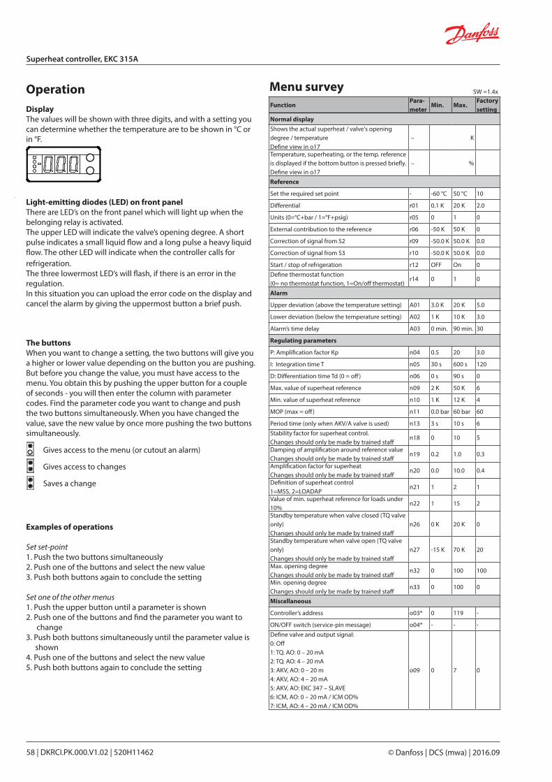
© Danfoss | DCS (mwa) | 2016.0958 | DKRCI.PK.000.V1.02 | 520H11462
Superheat controller, EKC 315A
Light-emitting diodes (LED) on front panelThere are LED’s on the front panel which will light up when the belonging relay is activated.The upper LED will indicate the valve’s opening degree. A short pulse indicates a small liquid flow and a long pulse a heavy liquid flow. The other LED will indicate when the controller calls for refrigeration.The three lowermost LED’s will flash, if there is an error in the regulation.In this situation you can upload the error code on the display and cancel the alarm by giving the uppermost button a brief push.
DisplayThe values will be shown with three digits, and with a setting you can determine whether the temperature are to be shown in °C or in °F.
Operation Menu survey
The buttonsWhen you want to change a setting, the two buttons will give you a higher or lower value depending on the button you are pushing. But before you change the value, you must have access to the menu. You obtain this by pushing the upper button for a couple of seconds - you will then enter the column with parameter codes. Find the parameter code you want to change and push the two buttons simultaneously. When you have changed the value, save the new value by once more pushing the two buttons simultaneously.
Gives access to the menu (or cutout an alarm)
Gives access to changes
Saves a change
Examples of operations
Set set-point1. Push the two buttons simultaneously2. Push one of the buttons and select the new value3. Push both buttons again to conclude the setting Set one of the other menus1. Push the upper button until a parameter is shown2. Push one of the buttons and find the parameter you want to
change3. Push both buttons simultaneously until the parameter value is
shown4. Push one of the buttons and select the new value5. Push both buttons again to conclude the setting
SW =1.4x
FunctionPara-meter
Min. Max.Factory setting
Normal displayShows the actual superheat / valve's opening degree / temperatureDefine view in o17
– K
Temperature, superheating, or the temp. reference is displayed if the bottom button is pressed briefly.Define view in o17
– %
Reference
Set the required set point - -60 °C 50 °C 10
Differential r01 0.1 K 20 K 2.0
Units (0=°C+bar / 1=°F+psig) r05 0 1 0
External contribution to the reference r06 -50 K 50 K 0
Correction of signal from S2 r09 -50.0 K 50.0 K 0.0
Correction of signal from S3 r10 -50.0 K 50.0 K 0.0
Start / stop of refrigeration r12 OFF On 0Define thermostat function(0= no thermostat function, 1=On/off thermostat)
r14 0 1 0
Alarm
Upper deviation (above the temperature setting) A01 3.0 K 20 K 5.0
Lower deviation (below the temperature setting) A02 1 K 10 K 3.0
Alarm’s time delay A03 0 min. 90 min. 30
Regulating parameters
P: Amplification factor Kp n04 0.5 20 3.0
I: Integration time T n05 30 s 600 s 120
D: Differentiation time Td (0 = off) n06 0 s 90 s 0
Max. value of superheat reference n09 2 K 50 K 6
Min. value of superheat reference n10 1 K 12 K 4
MOP (max = off) n11 0.0 bar 60 bar 60
Period time (only when AKV/A valve is used) n13 3 s 10 s 6Stability factor for superheat control.Changes should only be made by trained staff
n18 0 10 5
Damping of amplification around reference valueChanges should only be made by trained staff
n19 0.2 1.0 0.3
Amplification factor for superheatChanges should only be made by trained staff
n20 0.0 10.0 0.4
Definition of superheat control1=MSS, 2=LOADAP
n21 1 2 1
Value of min. superheat reference for loads under 10%
n22 1 15 2
Standby temperature when valve closed (TQ valve only)Changes should only be made by trained staff
n26 0 K 20 K 0
Standby temperature when valve open (TQ valve only)Changes should only be made by trained staff
n27 -15 K 70 K 20
Max. opening degreeChanges should only be made by trained staff
n32 0 100 100
Min. opening degreeChanges should only be made by trained staff
n33 0 100 0
Miscellaneous
Controller’s address o03* 0 119 -
ON/OFF switch (service-pin message) o04* - - -Define valve and output signal:0: Off1: TQ. AO: 0 – 20 mA2: TQ. AO: 4 – 20 mA3: AKV, AO: 0 – 20 m4: AKV, AO: 4 – 20 mA5: AKV, AO: EKC 347 – SLAVE6: ICM, AO: 0 – 20 mA / ICM OD%7: ICM, AO: 4 – 20 mA / ICM OD%
o09 0 7 0
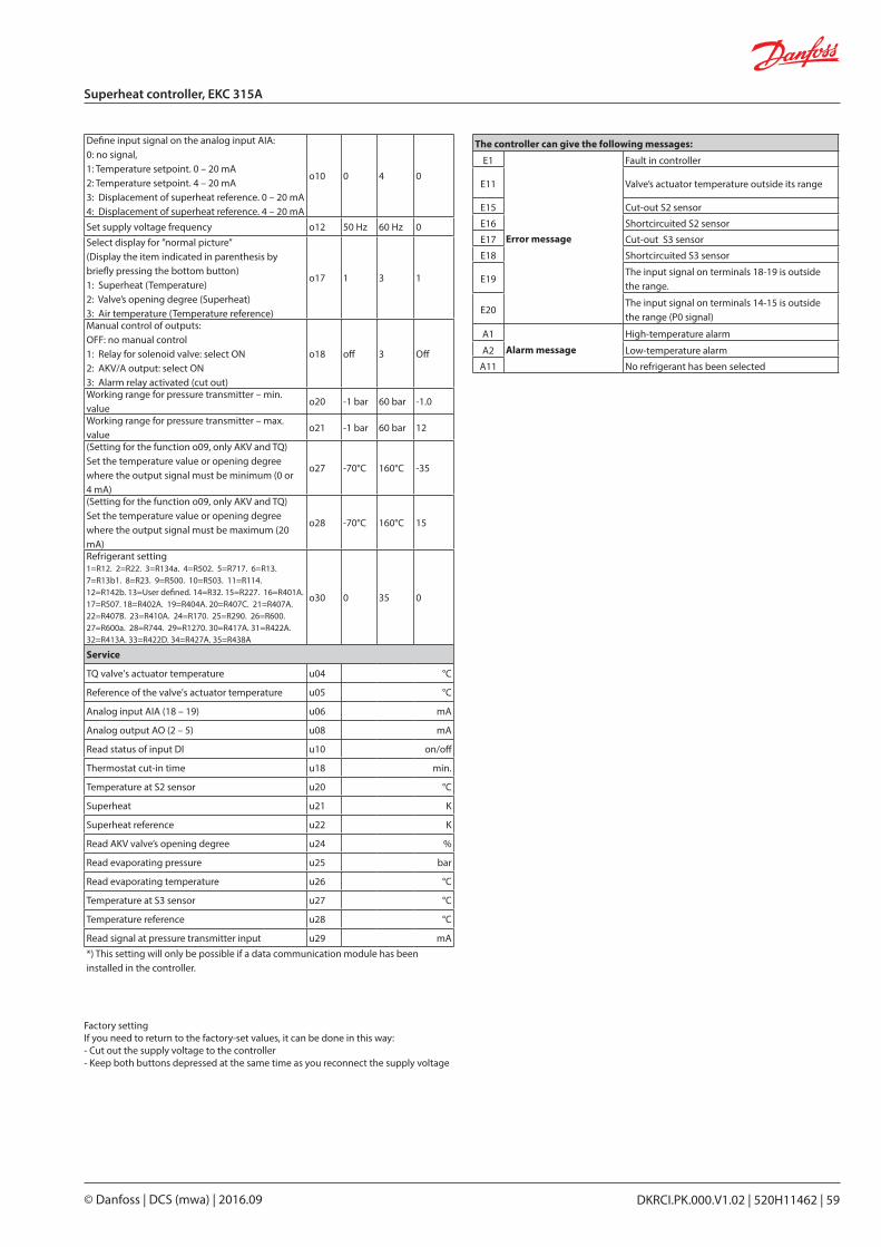
DKRCI.PK.000.V1.02 | 520H11462 | 59© Danfoss | DCS (mwa) | 2016.09
Superheat controller, EKC 315A
Factory settingIf you need to return to the factory-set values, it can be done in this way:- Cut out the supply voltage to the controller- Keep both buttons depressed at the same time as you recon nect the supply voltage
The controller can give the following messages:
E1
Error message
Fault in controller
E11 Valve’s actuator temperature outside its range
E15 Cut-out S2 sensor
E16 Shortcircuited S2 sensor
E17 Cut-out S3 sensor
E18 Shortcircuited S3 sensor
E19The input signal on terminals 18-19 is outside the range.
E20The input signal on terminals 14-15 is outside the range (P0 signal)
A1
Alarm messageHigh-temperature alarm
A2 Low-temperature alarm
A11 No refrigerant has been selected
Define input signal on the analog input AIA:0: no signal,1: Temperature setpoint. 0 – 20 mA2: Temperature setpoint. 4 – 20 mA3: Displacement of superheat reference. 0 – 20 mA4: Displacement of superheat reference. 4 – 20 mA
o10 0 4 0
Set supply voltage frequency o12 50 Hz 60 Hz 0Select display for ”normal picture”(Display the item indicated in parenthesis by briefly pressing the bottom button) 1: Superheat (Temperature)2: Valve’s opening degree (Superheat)3: Air temperature (Temperature reference)
o17 1 3 1
Manual control of outputs:OFF: no manual control 1: Relay for solenoid valve: select ON2: AKV/A output: select ON3: Alarm relay activated (cut out)
o18 off 3 Off
Working range for pressure transmitter – min. value
o20 -1 bar 60 bar -1.0
Working range for pressure transmitter – max. value
o21 -1 bar 60 bar 12
(Setting for the function o09, only AKV and TQ)Set the temperature value or opening degree where the output signal must be minimum (0 or 4 mA)
o27 -70°C 160°C -35
(Setting for the function o09, only AKV and TQ)Set the temperature value or opening degree where the output signal must be maximum (20 mA)
o28 -70°C 160°C 15
Refrigerant setting1=R12. 2=R22. 3=R134a. 4=R502. 5=R717. 6=R13. 7=R13b1. 8=R23. 9=R500. 10=R503. 11=R114. 12=R142b. 13=User defined. 14=R32. 15=R227. 16=R401A. 17=R507. 18=R402A. 19=R404A. 20=R407C. 21=R407A. 22=R407B. 23=R410A. 24=R170. 25=R290. 26=R600. 27=R600a. 28=R744. 29=R1270. 30=R417A. 31=R422A. 32=R413A. 33=R422D. 34=R427A. 35=R438A
o30 0 35 0
Service
TQ valve's actuator temperature u04 °C
Reference of the valve's actuator temperature u05 °C
Analog input AIA (18 – 19) u06 mA
Analog output AO (2 – 5) u08 mA
Read status of input DI u10 on/off
Thermostat cut-in time u18 min.
Temperature at S2 sensor u20 °C
Superheat u21 K
Superheat reference u22 K
Read AKV valve’s opening degree u24 %
Read evaporating pressure u25 bar
Read evaporating temperature u26 °C
Temperature at S3 sensor u27 °C
Temperature reference u28 °C
Read signal at pressure transmitter input u29 mA*) This setting will only be possible if a data communication module has been installed in the controller.
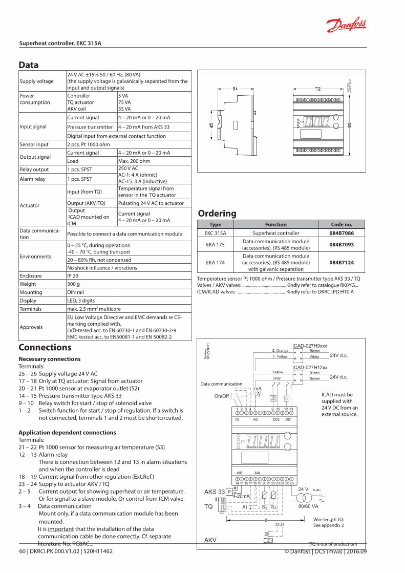
© Danfoss | DCS (mwa) | 2016.0960 | DKRCI.PK.000.V1.02 | 520H11462
Superheat controller, EKC 315A
Data
Ordering
Data communication
Supply voltage24 V AC ±15% 50 / 60 Hz, (80 VA)(the supply voltage is galvanically separated from the input and output signals)
Power consumption
ControllerTQ actuatorAKV coil
5 VA75 VA55 VA
Input signal
Current signal 4 – 20 mA or 0 – 20 mA
Pressure transmitter 4 – 20 mA from AKS 33
Digital input from external contact function
Sensor input 2 pcs. Pt 1000 ohm
Output signalCurrent signal 4 – 20 mA or 0 – 20 mA
Load Max. 200 ohm
Relay output 1 pcs. SPST 250 V ACAC-1: 4 A (ohmic)AC-15: 3 A (inductive)Alarm relay 1 pcs. SPST
Actuator
Input (from TQ) Temperature signal from sensor in the TQ actuator
Output (AKV, TQ) Pulsating 24 V AC to actuator Output ICAD mounted on ICM
Current signal 4 – 20 mA or 0 – 20 mA
Data communica-tion Possible to connect a data communication module
Environments
0 – 55 °C, during operations-40 – 70 °C, during transport20 – 80% Rh, not condensedNo shock influence / vibrations
Enclosure IP 20Weight 300 g
Mounting DIN rail
Display LED, 3 digits
Terminals max. 2.5 mm2 multicore
Approvals
EU Low Voltage Directive and EMC demands re CE-marking complied with.LVD-tested acc. to EN 60730-1 and EN 60730-2-9EMC-tested acc. to EN50081-1 and EN 50082-2
Type Function Code no.
EKC 315A Superheat controller 084B7086
EKA 175 Data communication module (accessories), (RS 485 module) 084B7093
EKA 174Data communication module (accessories), (RS 485 module)
with galvanic separation084B7124
Temperature sensor Pt 1000 ohm / Pressure transmitter type AKS 33 / TQ Valves / AKV valves: ............. .........................Kindly refer to catalogue RK0YG...ICM/ICAD valves: ...........................................Kindly refer to DKRCI.PD.HT0.A
Necessary connectionsTerminals:25 – 26 Supply voltage 24 V AC17 – 18 Only at TQ actuator: Signal from actuator20 – 21 Pt 1000 sensor at evaporator outlet (S2)14 – 15 Pressure transmitter type AKS 339 – 10 Relay switch for start / stop of solenoid valve1 – 2 Switch function for start / stop of regulation. If a switch is
not connected, terminals 1 and 2 must be shortcircuited.
Application dependent connectionsTerminals:21 – 22 Pt 1000 sensor for measuring air temperature (S3)12 – 13 Alarm relay
There is connection between 12 and 13 in alarm situa tions and when the controller is dead
18 – 19 Current signal from other regulation (Ext.Ref.)23 – 24 Supply to actuator AKV / TQ2 – 5 Current output for showing superheat or air temperature.
Or for signal to a slave module. Or control from ICM valve.3 – 4 Data communication Mount only, if a data communication module has been
mounted.It is important that the installation of the data communication cable be done correctly. Cf. separate literature No. RC8AC...
Connections
Wire length TQ: See appendix 2
(TQ is out of production)
ICAD must be supplied with 24 V DC from an external source.
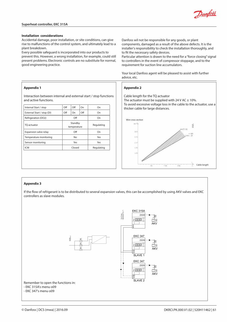
DKRCI.PK.000.V1.02 | 520H11462 | 61© Danfoss | DCS (mwa) | 2016.09
Superheat controller, EKC 315A
Installation considerationsAccidental damage, poor installation, or site conditions, can give rise to malfunctions of the control system, and ultimately lead to a plant breakdown.Every possible safeguard is incorporated into our products to prevent this. However, a wrong installation, for example, could still present problems. Electronic controls are no substitute for normal, good engineering practice.
Danfoss wil not be responsible for any goods, or plant components, damaged as a result of the above defects. It is the installer's responsibility to check the installation thoroughly, and to fit the necessary safety devices.Particular attention is drawn to the need for a “force closing” signal to controllers in the event of compressor stoppage, and to the requirement for suction line accumulators.
Your local Danfoss agent will be pleased to assist with further advice, etc.
Appendix 1
Interaction between internal and external start / stop functions and active functions.
Appendix 2
Cable length for the TQ actuatorThe actuator must be supplied with 24 V AC ± 10%.To avoid excessive voltage loss in the cable to the actuator, use a thicker cable for large distances.
Wire cross section
Cable length
Internal Start / stop Off Off On On
External Start / stop (DI) Off On Off On
Refrigeration (DO2) Off On
TQ actuatorStandby
temperatureRegulating
Expansion valve relay Off On
Temperature monitoring No Yes
Sensor monitoring Yes Yes
ICM Closed Regulating
Appendix 3
If the flow of refrigerant is to be distributed to several expansion valves, this can be accomplished by using AKV valves and EKC controllers as slave modules.
Remember to open the functions in:- EKC 315A's menu o09- EKC 347's menu o09
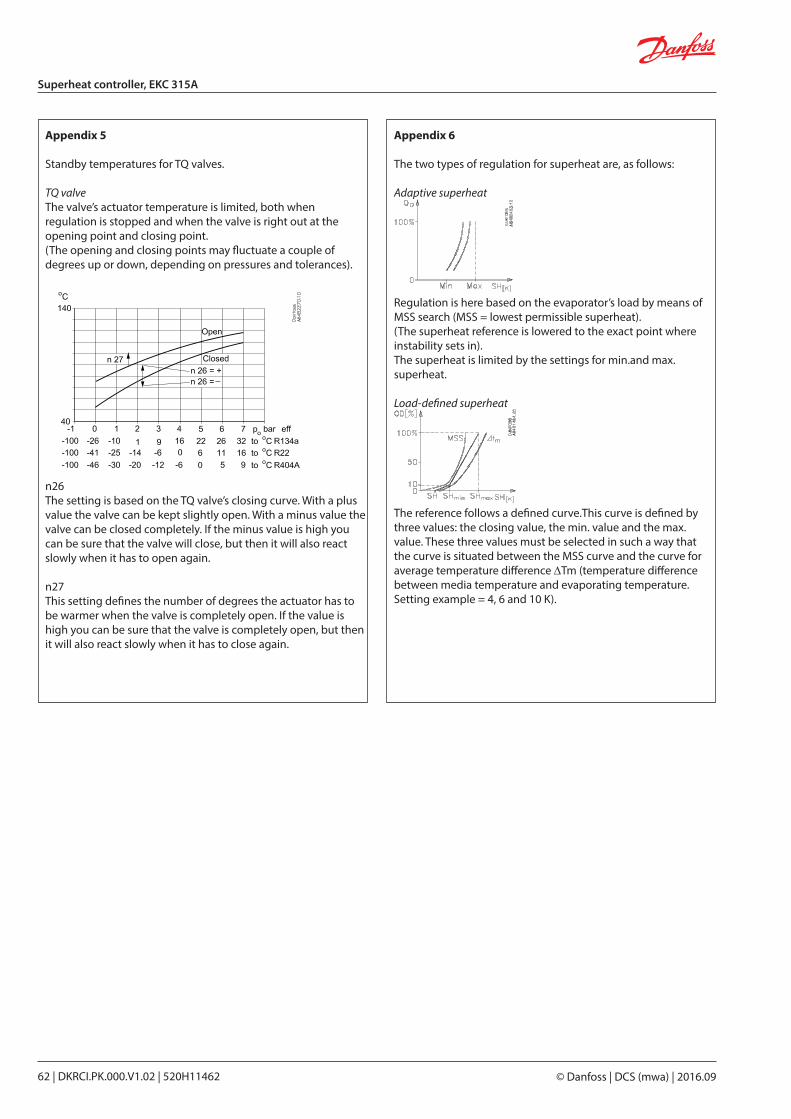
© Danfoss | DCS (mwa) | 2016.0962 | DKRCI.PK.000.V1.02 | 520H11462
Superheat controller, EKC 315A
Appendix 5
Standby temperatures for TQ valves.
TQ valveThe valve’s actuator temperature is limited, both when regulation is stopped and when the valve is right out at the opening point and closing point.(The opening and closing points may fluctuate a couple of degrees up or down, depending on pressures and tolerances).
n26The setting is based on the TQ valve’s closing curve. With a plus value the valve can be kept slightly open. With a minus value the valve can be closed completely. If the minus value is high you can be sure that the valve will close, but then it will also react slowly when it has to open again.
n27This setting defines the number of degrees the actuator has to be warmer when the valve is completely open. If the value is high you can be sure that the valve is completely open, but then it will also react slowly when it has to close again.
Appendix 6
The two types of regulation for superheat are, as follows:
Adaptive superheat
Regulation is here based on the evaporator’s load by means of MSS search (MSS = lowest permissible superheat).(The superheat reference is lowered to the exact point where instability sets in).The superheat is limited by the settings for min.and max.superheat.
Load-defined superheat
The reference follows a defined curve.This curve is defined by three values: the closing value, the min. value and the max. value. These three values must be selected in such a way that the curve is situated between the MSS curve and the curve for average temperature difference ∆Tm (temperature difference between media temperature and evaporating temperature.Setting example = 4, 6 and 10 K).
DKRCI.PK.000.V1.02 | 520H11462 | 63© Danfoss | DCS (mwa) | 2016.09
Superheat controller, EKC 315A
Start of controller
When the electric wires have been connected to the controller, the following points have to be attended to before the regulation starts:1. Switch off the external ON / OFF switch that starts and stops the
regulation.2. Follow the menu survey on page 58, and set the various
parameters to the required values.3. Switch on the external switch, and regulation will start.
If the superheating fluctuates
When the refrigerating system has been made to work steadily, the controller’s factory-set control parameters should in most cases provide a stable and relatively fast regulating system.If the system however fluctuates this may be due to the fact that too low superheat parameters have been selected:
If adaptive superheat has been selected:Adjust: n09, n10 and n18.
If load-defined superheat has been selected:Adjust: n09, n10 and n22.
Alternatively it may be due to the fact that the set regulation parameters are not optimal.
If the time of oscillation is longer than the integration time:(Tp > Tn , (Tn is, say, 240 seconds))1. Increase Tn to 1.2 times Tp
2. Wait until the system is in balance again3. If there is still oscillation, reduce Kp by, say, 20%4. Wait until the system is in balance5. If it continues to oscillate, repeat 3 and 4
If the time of oscillation is shorter than the integration time:(Tp < Tn , (Tn is, say, 240 seconds))1. Reduce Kp by, say, 20% of the scale reading2. Wait until the system is in balance3. If it continues to oscillate, repeat 1 and 2.
4. Follow the actual room temperature or superheat on the display. (On terminals 2 and 5 a current signal can be transmitted which represents the display view. Connect a data collection unit, if applicable, so that the temperature performance can be followed).
If the superheat has excessive underswing during start-up
If you regulate with valve type ICM or AKV:Adjust n22 a little bit up and / or n04 a little bit down.
If you regulate with valve type TQ:Adjust n26 a littlle bit down

RS8EB102 | 2005.09
Contents Page
System . . . . . . . . . . . . . . . . . . . . . . . . . . . . . . . . . . . . . . . . . . . . . . . . . . . . . . . . . . . . . . . . . . . . . . . . . . . . . . . . . . . . . . . . . . . 67
Temperature sensor . . . . . . . . . . . . . . . . . . . . . . . . . . . . . . . . . . . . . . . . . . . . . . . . . . . . . . . . . . . . . . . . . . . . . . . . . . . . . . 67
Valve . . . . . . . . . . . . . . . . . . . . . . . . . . . . . . . . . . . . . . . . . . . . . . . . . . . . . . . . . . . . . . . . . . . . . . . . . . . . . . . . . . . . . . . . . . . . . 67
Alarm function . . . . . . . . . . . . . . . . . . . . . . . . . . . . . . . . . . . . . . . . . . . . . . . . . . . . . . . . . . . . . . . . . . . . . . . . . . . . . . . . . . . 67
Extra options . . . . . . . . . . . . . . . . . . . . . . . . . . . . . . . . . . . . . . . . . . . . . . . . . . . . . . . . . . . . . . . . . . . . . . . . . . . . . . . . . . . . . 68
Survey of functions . . . . . . . . . . . . . . . . . . . . . . . . . . . . . . . . . . . . . . . . . . . . . . . . . . . . . . . . . . . . . . . . . . . . . . . . . . . . . . . 69
Operation . . . . . . . . . . . . . . . . . . . . . . . . . . . . . . . . . . . . . . . . . . . . . . . . . . . . . . . . . . . . . . . . . . . . . . . . . . . . . . . . . . . . . . . . 71
Menu survey . . . . . . . . . . . . . . . . . . . . . . . . . . . . . . . . . . . . . . . . . . . . . . . . . . . . . . . . . . . . . . . . . . . . . . . . . . . . . . . . . . . . . 71
Connnections . . . . . . . . . . . . . . . . . . . . . . . . . . . . . . . . . . . . . . . . . . . . . . . . . . . . . . . . . . . . . . . . . . . . . . . . . . . . . . . . . . . . 72
Data. . . . . . . . . . . . . . . . . . . . . . . . . . . . . . . . . . . . . . . . . . . . . . . . . . . . . . . . . . . . . . . . . . . . . . . . . . . . . . . . . . . . . . . . . . . . . . 72
Ordering . . . . . . . . . . . . . . . . . . . . . . . . . . . . . . . . . . . . . . . . . . . . . . . . . . . . . . . . . . . . . . . . . . . . . . . . . . . . . . . . . . . . . . . . . 72
Data communication . . . . . . . . . . . . . . . . . . . . . . . . . . . . . . . . . . . . . . . . . . . . . . . . . . . . . . . . . . . . . . . . . . . . . . . . . . . . . 73
Shut-off and regulating valves for Industrial Refrigeration
DKRCI.PK.000.V1.02 | 520H11462 | 65© Danfoss | DCS (mwa) | 2016.09
Temperature controller EKC 319A

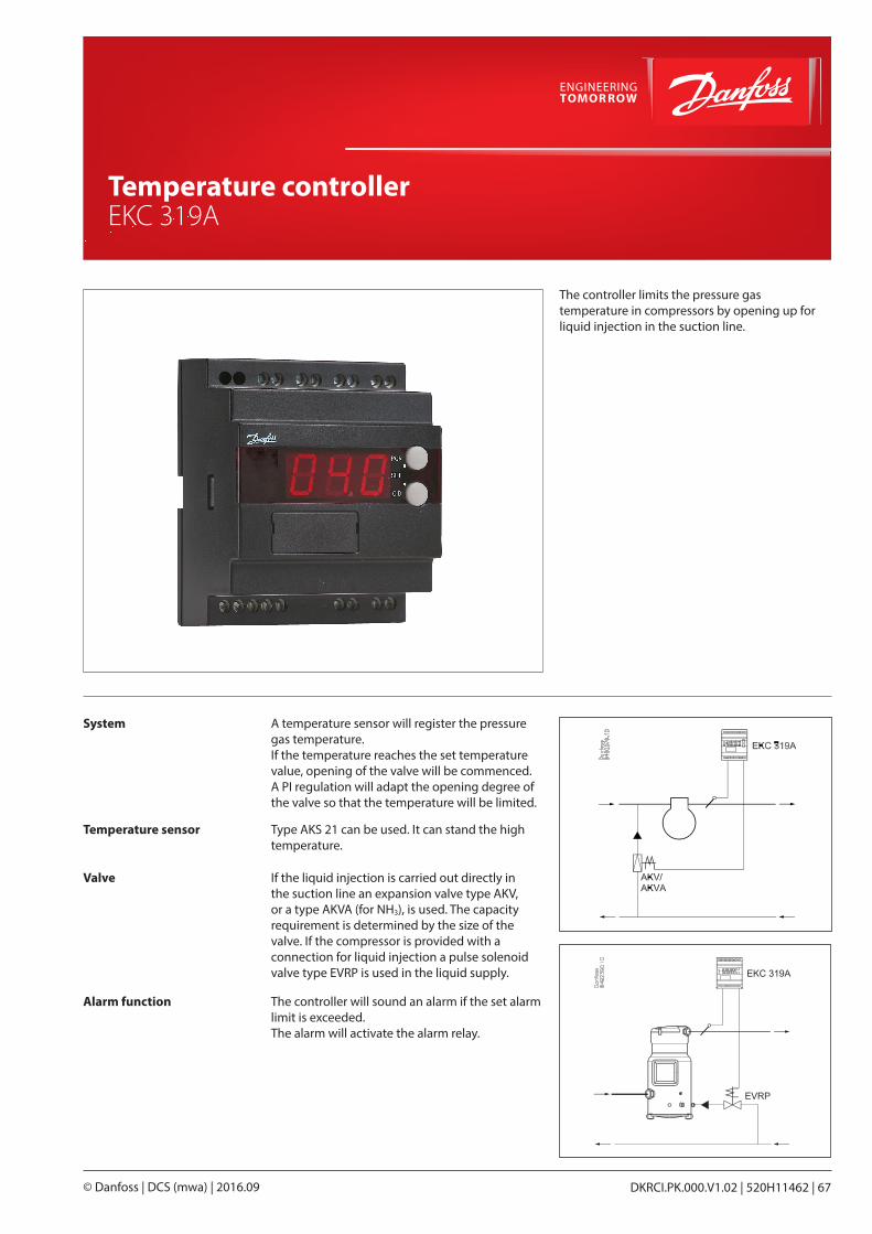
The controller limits the pressure gas temperature in compressors by opening up for liquid injection in the suction line.
System A temperature sensor will register the pressure gas temperature.If the temperature reaches the set temperature value, opening of the valve will be commenced.A PI regulation will adapt the opening degree of the valve so that the temperature will be limited.
Temperature sensor Type AKS 21 can be used. It can stand the high temperature.
Valve If the liquid injection is carried out directly in the suction line an expansion valve type AKV, or a type AKVA (for NH3), is used. The capacity requirement is determined by the size of the valve. If the compressor is provided with a connection for liquid injection a pulse solenoid valve type EVRP is used in the liquid supply.
Alarm function The controller will sound an alarm if the set alarm limit is exceeded.The alarm will activate the alarm relay.
Shut-off and regulating valves for Industrial Refrigeration
DKRCI.PK.000.V1.02 | 520H11462 | 67© Danfoss | DCS (mwa) | 2016.09
Temperature controller EKC 319A
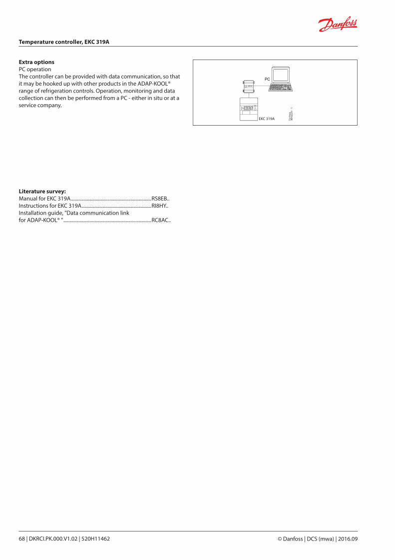
Extra optionsPC operationThe controller can be provided with data communication, so that it may be hooked up with other products in the ADAP-KOOL® range of refrigeration controls. Operation, moni toring and data collection can then be performed from a PC - either in situ or at a service company.
EKC 319A
Literature survey:Manual for EKC 319A .................................................................RS8EB..Instructions for EKC 319A ........................................................RI8HY..Installation guide, "Data communication linkfor ADAP-KOOL® " .......................................................................RC8AC..
Temperature controller, EKC 319A
© Danfoss | DCS (mwa) | 2016.0968 | DKRCI.PK.000.V1.02 | 520H11462
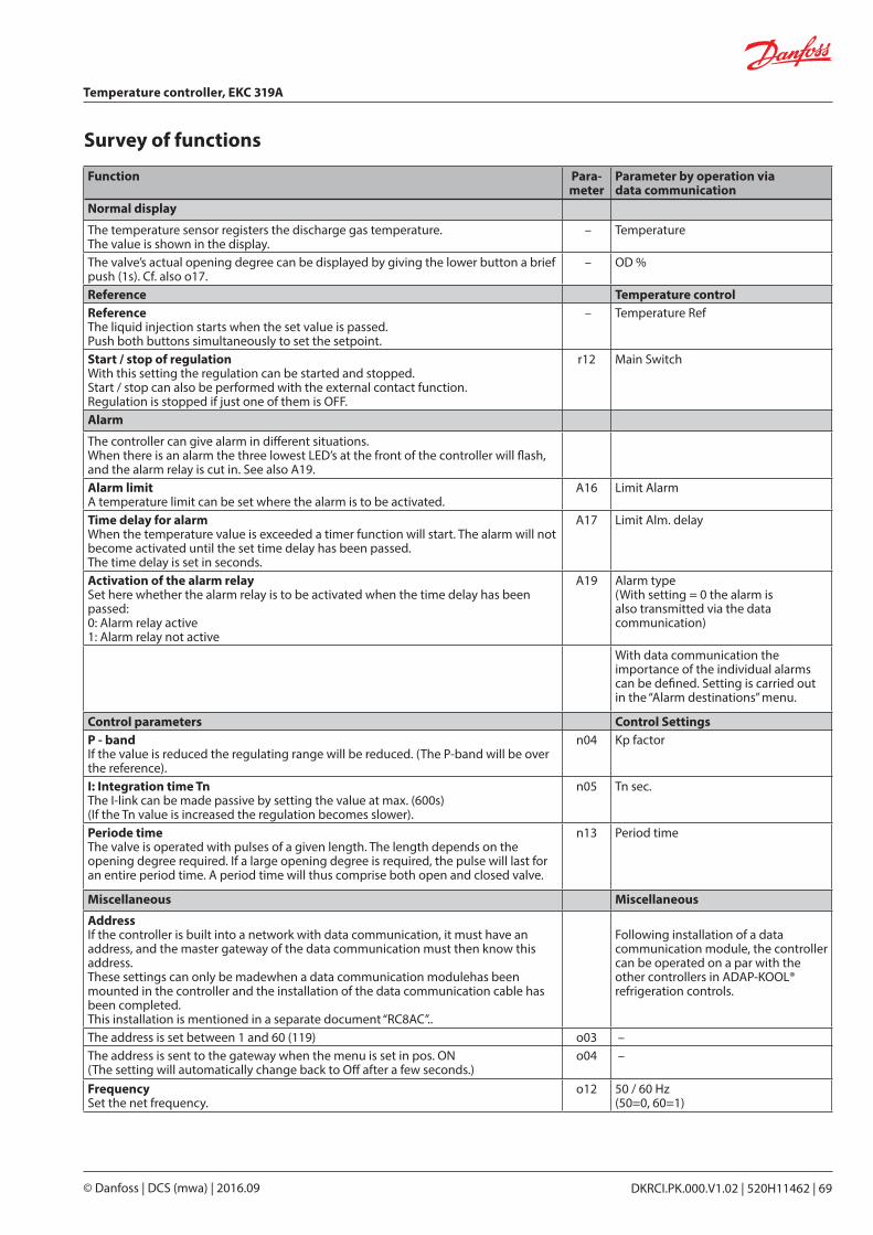
Survey of functions
Function Para- meter
Parameter by operation via data communication
Normal display
The temperature sensor registers the discharge gas temperature.The value is shown in the display.
– Temperature
The valve’s actual opening degree can be displayed by giving the lower button a brief push (1s). Cf. also o17.
– OD %
Reference Temperature controlReferenceThe liquid injection starts when the set value is passed.Push both buttons simultaneously to set the setpoint.
– Temperature Ref
Start / stop of regulationWith this setting the regulation can be started and stopped. Start / stop can also be performed with the external contact function.Regulation is stopped if just one of them is OFF.
r12 Main Switch
Alarm
The controller can give alarm in different situations.When there is an alarm the three lowest LED’s at the front of the controller will flash, and the alarm relay is cut in. See also A19.Alarm limitA temperature limit can be set where the alarm is to be activated.
A16 Limit Alarm
Time delay for alarmWhen the temperature value is exceeded a timer function will start. The alarm will not become activated until the set time delay has been passed.The time delay is set in seconds.
A17 Limit Alm. delay
Activation of the alarm relaySet here whether the alarm relay is to be activated when the time delay has been passed:0: Alarm relay active1: Alarm relay not active
A19 Alarm type (With setting = 0 the alarm is also transmitted via the data communication)
With data communication the importance of the individual alarms can be defined. Setting is carried out in the “Alarm destinations” menu.
Control parameters Control SettingsP - bandIf the value is reduced the regulating range will be reduced. (The P-band will be over the reference).
n04 Kp factor
I: Integration time TnThe I-link can be made passive by setting the value at max. (600s)(If the Tn value is increased the regulation becomes slower).
n05 Tn sec.
Periode timeThe valve is operated with pulses of a given length. The length depends on the opening degree required. If a large opening degree is required, the pulse will last for an entire period time. A period time will thus comprise both open and closed valve.
n13 Period time
Miscellaneous Miscellaneous
AddressIf the controller is built into a network with data communication, it must have an address, and the master gateway of the data communication must then know this address.These settings can only be madewhen a data communication modulehas been mounted in the controller and the installation of the data communication cable has been completed.This installation is mentioned in a separate document “RC8AC”..
Following installation of a data communication module, the controller can be operated on a par with the other controllers in ADAP-KOOL® refrigeration controls.
The address is set between 1 and 60 (119) o03 – The address is sent to the gateway when the menu is set in pos. ON(The setting will automatically change back to Off after a few seconds.)
o04 –
FrequencySet the net frequency.
o12 50 / 60 Hz(50=0, 60=1)
Temperature controller, EKC 319A
DKRCI.PK.000.V1.02 | 520H11462 | 69© Danfoss | DCS (mwa) | 2016.09
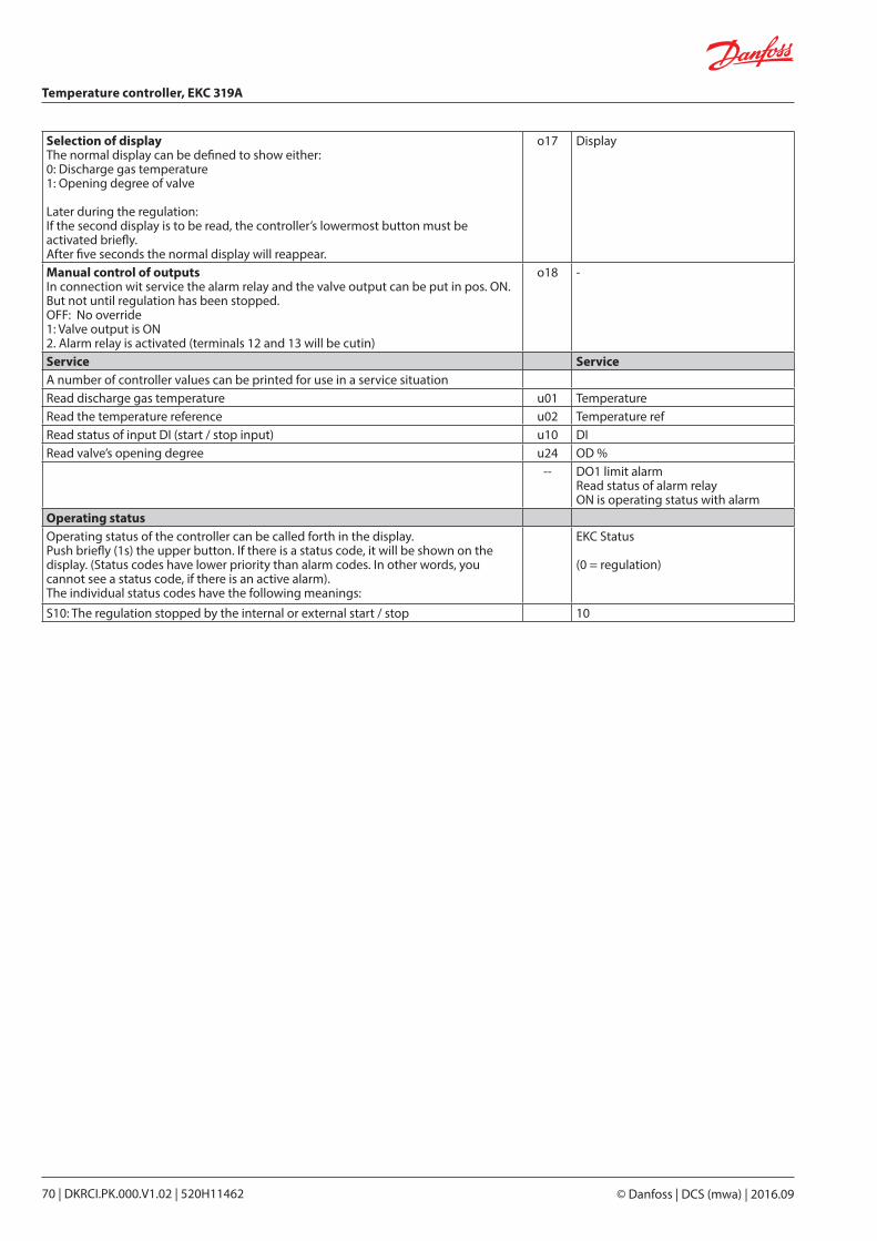
Selection of displayThe normal display can be defined to show either:0: Discharge gas temperature1: Opening degree of valve
Later during the regulation:If the second display is to be read, the controller’s lowermost button must be activated briefly.After five seconds the normal display will reappear.
o17 Display
Manual control of outputsIn connection wit service the alarm relay and the valve output can be put in pos. ON. But not until regulation has been stopped.OFF: No override1: Valve output is ON2. Alarm relay is activated (terminals 12 and 13 will be cutin)
o18 -
Service ServiceA number of controller values can be printed for use in a service situationRead discharge gas temperature u01 TemperatureRead the temperature reference u02 Temperature refRead status of input DI (start / stop input) u10 DIRead valve’s opening degree u24 OD %
-- DO1 limit alarmRead status of alarm relayON is operating status with alarm
Operating statusOperating status of the controller can be called forth in the display.Push briefly (1s) the upper button. If there is a status code, it will be shown on the display. (Status codes have lower priority than alarm codes. In other words, you cannot see a status code, if there is an active alarm).The individual status codes have the following meanings:
EKC Status
(0 = regulation)
S10: The regulation stopped by the internal or external start / stop 10
Temperature controller, EKC 319A
© Danfoss | DCS (mwa) | 2016.0970 | DKRCI.PK.000.V1.02 | 520H11462
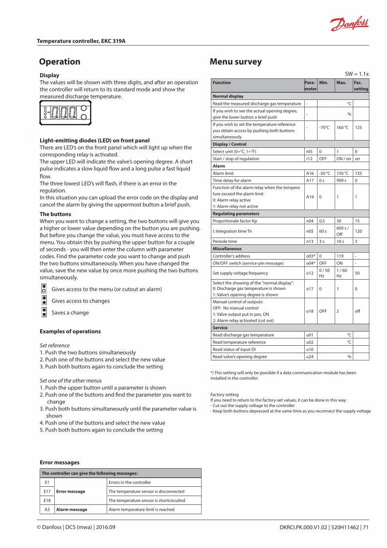
Operation Menu survey
Light-emitting diodes (LED) on front panelThere are LED’s on the front panel which will light up when the corresponding relay is activated.The upper LED will indicate the valve’s opening degree. A short pulse indicates a slow liquid flow and a long pulse a fast liquid flow.The three lowest LED’s will flash, if there is an error in the regulation.In this situation you can upload the error code on the display and cancel the alarm by giving the uppermost button a brief push.
DisplayThe values will be shown with three digits, and after an operation the controller will return to its standard mode and show the measured discharge temperature.
The buttonsWhen you want to change a setting, the two buttons will give you a higher or lower value depending on the button you are pushing. But before you change the value, you must have access to the menu. You obtain this by pushing the upper button for a couple of seconds - you will then enter the column with parameter codes. Find the parameter code you want to change and push the two buttons simultaneously. When you have changed the value, save the new value by once more pushing the two buttons simultaneously.
Gives access to the menu (or cutout an alarm)
Gives access to changes
Saves a change
Examples of operations
Set reference1. Push the two buttons simultaneously2. Push one of the buttons and select the new value3. Push both buttons again to conclude the setting Set one of the other menus1. Push the upper button until a parameter is shown2. Push one of the buttons and find the parameter you want to
change3. Push both buttons simultaneously until the parameter value is
shown4. Push one of the buttons and select the new value5. Push both buttons again to conclude the setting
SW = 1.1xFunction Para-
meterMin. Max. Fac.
setting
Normal display
Read the measured discharge gas temperature - °C
If you wish to see the actual opening degree, give the lower button a brief push
- %
If you wish to set the temperature reference you obtain access by pushing both buttons simultaneously
- -70°C 160 °C 125
Display / Control
Select unit (0=°C, 1=°F) r05 0 1 0
Start / stop of regulation r12 OFF ON / on on
Alarm
Alarm limit A16 -50 °C 150 °C 135
Time delay for alarm A17 0 s 999 s 0
Function of the alarm relay when the tempera-ture exceed the alarm limit 0: Alarm relay active1: Alarm relay not active
A19 0 1 1
Regulating parameters
Proportionale factor Kp n04 0,5 30 15
I: Integration time Tn n05 60 s600 s / Off
120
Periode time n13 3 s 10 s 3
Miscellaneous
Controller's address o03* 0 119 -
ON/OFF switch (service-pin message) o04* OFF ON -
Set supply voltage frequency o12 0 / 50 Hz
1 / 60 Hz 50
Select the showing of the "normal display":0: Discharge gas temperature is shown1: Valve’s opening degree is shown
o17 0 1 0
Manual control of outputs:OFF: No manual control1: Valve output put in pos. ON2: Alarm relay activated (cut out)
o18 OFF 2 off
Service
Read discharge gas temperature u01 °C
Read temperature reference u02 °C
Read status of input DI u10
Read valve’s opening degree u24 %
Error messages
The controller can give the following messages:
E1
Error message
Errors in the controller
E17 The temperature sensor is disconnected
E18 The temperature sensor is shortcircuited
A3 Alarm message Alarm temperature limit is reached
*) This setting will only be possible if a data communication module has been installed in the controller.
Factory settingIf you need to return to the factory-set values, it can be done in this way:- Cut out the supply voltage to the controller- Keep both buttons depressed at the same time as you recon nect the supply voltage
Temperature controller, EKC 319A
DKRCI.PK.000.V1.02 | 520H11462 | 71© Danfoss | DCS (mwa) | 2016.09
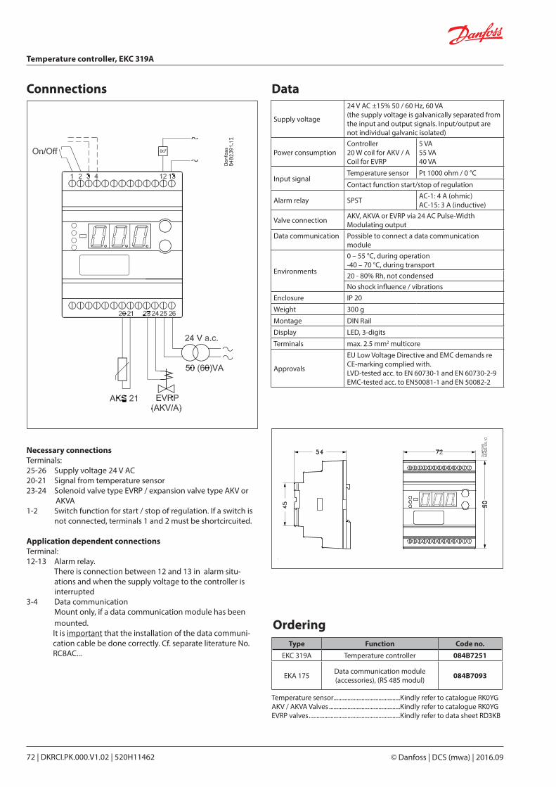
Data
OrderingType Function Code no.
EKC 319A Temperature controller 084B7251
EKA 175 Data communication module (accessories), (RS 485 modul) 084B7093
Supply voltage
24 V AC ±15% 50 / 60 Hz, 60 VA(the supply voltage is galvanically separated from the input and output signals. Input/output are not individual galvanic isolated)
Power consumptionController20 W coil for AKV / ACoil for EVRP
5 VA55 VA40 VA
Input signal Temperature sensor Pt 1000 ohm / 0 °C
Contact function start/stop of regulation
Alarm relay SPST AC-1: 4 A (ohmic)AC-15: 3 A (inductive)
Valve connection AKV, AKVA or EVRP via 24 AC Pulse-Width Modulating output
Data communication Possible to connect a data communication module
Environments
0 – 55 °C, during operation-40 – 70 °C, during transport20 - 80% Rh, not condensedNo shock influence / vibrations
Enclosure IP 20
Weight 300 g
Montage DIN Rail
Display LED, 3-digits
Terminals max. 2.5 mm2 multicore
Approvals
EU Low Voltage Directive and EMC demands re CE-marking complied with.LVD-tested acc. to EN 60730-1 and EN 60730-2-9EMC-tested acc. to EN50081-1 and EN 50082-2
Temperature sensor ...........................................Kindly refer to catalogue RK0YGAKV / AKVA Valves ..............................................Kindly refer to catalogue RK0YGEVRP valves ...........................................................Kindly refer to data sheet RD3KB
Connnections
Necessary connectionsTerminals:25-26 Supply voltage 24 V AC20-21 Signal from temperature sensor23-24 Solenoid valve type EVRP / expansion valve type AKV or
AKVA1-2 Switch function for start / stop of regulation. If a switch is
not connected, terminals 1 and 2 must be shortcircuited.
Application dependent connectionsTerminal:12-13 Alarm relay.
There is connection between 12 and 13 in alarm situ-ations and when the supply voltage to the controller is interrupted
3-4 Data communication Mount only, if a data communication module has been
mounted.It is important that the installation of the data communi-cation cable be done correctly. Cf. separate literature No. RC8AC...
Temperature controller, EKC 319A
© Danfoss | DCS (mwa) | 2016.0972 | DKRCI.PK.000.V1.02 | 520H11462
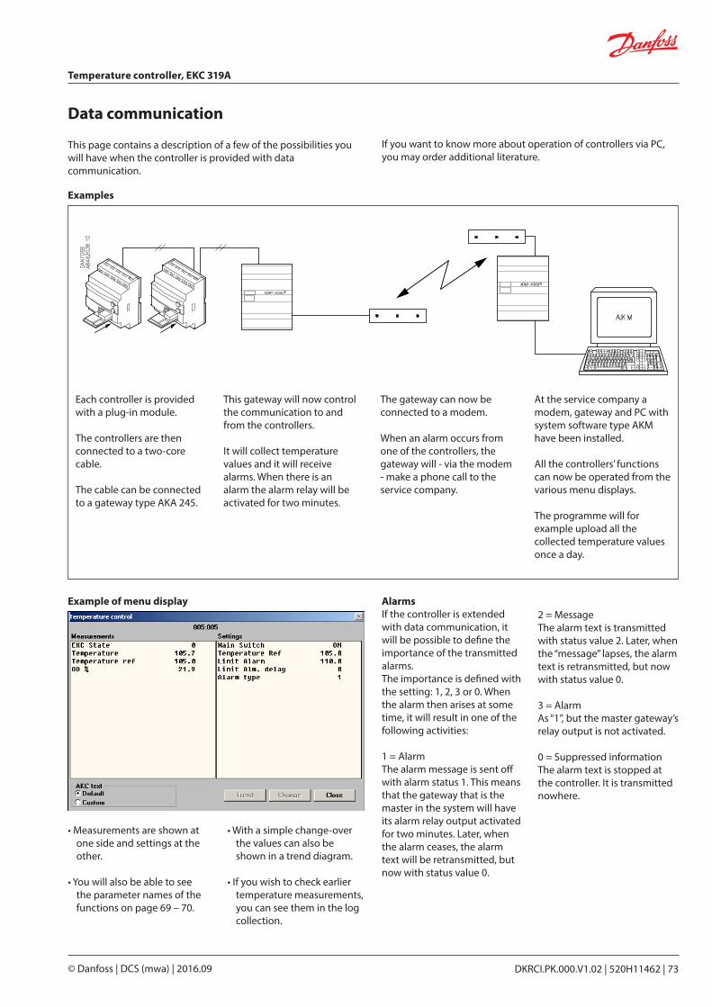
Data communication
Examples
If you want to know more about operation of controllers via PC, you may order additional literature.
This page contains a description of a few of the possibilities you will have when the controller is provided with data communi cation.
Each controller is provided with a plug-in module.
The controllers are then connected to a two-core cable.
The cable can be connected to a gateway type AKA 245.
This gateway will now control the communication to and from the controllers.
It will collect temperature values and it will receive alarms. When there is an alarm the alarm relay will be activated for two minutes.
The gateway can now be connected to a modem.
When an alarm occurs from one of the controllers, the gateway will - via the modem - make a phone call to the service company.
At the service company a modem, gateway and PC with system software type AKM have been installed.
All the controllers’ functions can now be operated from the various menu displays.
The programme will for example upload all the collected tempera ture values once a day.
Example of menu display
• Measurements are shown at one side and settings at the other.
• You will also be able to see the parameter names of the functions on page 69 – 70.
• With a simple change-over the values can also be shown in a trend diagram.
• If you wish to check earlier temperature measurements, you can see them in the log collection.
AlarmsIf the controller is extended with data communication, it will be possible to define the importance of the transmitted alarms.The importance is defined with the setting: 1, 2, 3 or 0. When the alarm then arises at some time, it will result in one of the following activities:
1 = AlarmThe alarm message is sent off with alarm status 1. This means that the gateway that is the master in the system will have its alarm relay output activated for two minutes. Later, when the alarm ceases, the alarm text will be retransmitted, but now with status value 0.
2 = MessageThe alarm text is transmitted with status value 2. Later, when the “message” lapses, the alarm text is retransmitted, but now with status value 0.
3 = AlarmAs “1”, but the master gateway’s relay output is not activated.
0 = Suppressed informationThe alarm text is stopped at the controller. It is transmitted nowhere.
Temperature controller, EKC 319A
DKRCI.PK.000.V1.02 | 520H11462 | 73© Danfoss | DCS (mwa) | 2016.09

RSAG202 | 2000.10
Contents Page
Advantages . . . . . . . . . . . . . . . . . . . . . . . . . . . . . . . . . . . . . . . . . . . . . . . . . . . . . . . . . . . . . . . . . . . . . . . . . . . . . . . . . . . . . . 77
Function . . . . . . . . . . . . . . . . . . . . . . . . . . . . . . . . . . . . . . . . . . . . . . . . . . . . . . . . . . . . . . . . . . . . . . . . . . . . . . . . . . . . . . . . . 77
Survey of functions . . . . . . . . . . . . . . . . . . . . . . . . . . . . . . . . . . . . . . . . . . . . . . . . . . . . . . . . . . . . . . . . . . . . . . . . . . . . . . . 79
Operation . . . . . . . . . . . . . . . . . . . . . . . . . . . . . . . . . . . . . . . . . . . . . . . . . . . . . . . . . . . . . . . . . . . . . . . . . . . . . . . . . . . . . . . . 82
Menu survey . . . . . . . . . . . . . . . . . . . . . . . . . . . . . . . . . . . . . . . . . . . . . . . . . . . . . . . . . . . . . . . . . . . . . . . . . . . . . . . . . . . . . 82
Data. . . . . . . . . . . . . . . . . . . . . . . . . . . . . . . . . . . . . . . . . . . . . . . . . . . . . . . . . . . . . . . . . . . . . . . . . . . . . . . . . . . . . . . . . . . . . . 83
Connections. . . . . . . . . . . . . . . . . . . . . . . . . . . . . . . . . . . . . . . . . . . . . . . . . . . . . . . . . . . . . . . . . . . . . . . . . . . . . . . . . . . . . . 83
Ordering . . . . . . . . . . . . . . . . . . . . . . . . . . . . . . . . . . . . . . . . . . . . . . . . . . . . . . . . . . . . . . . . . . . . . . . . . . . . . . . . . . . . . . . . . 83
Data communication . . . . . . . . . . . . . . . . . . . . . . . . . . . . . . . . . . . . . . . . . . . . . . . . . . . . . . . . . . . . . . . . . . . . . . . . . . . . . 84
Shut-off and regulating valves for Industrial Refrigeration
DKRCI.PK.000.V1.02 | 520H11462 | 75© Danfoss | DCS (mwa) | 2016.09
Capacity controller EKC 331

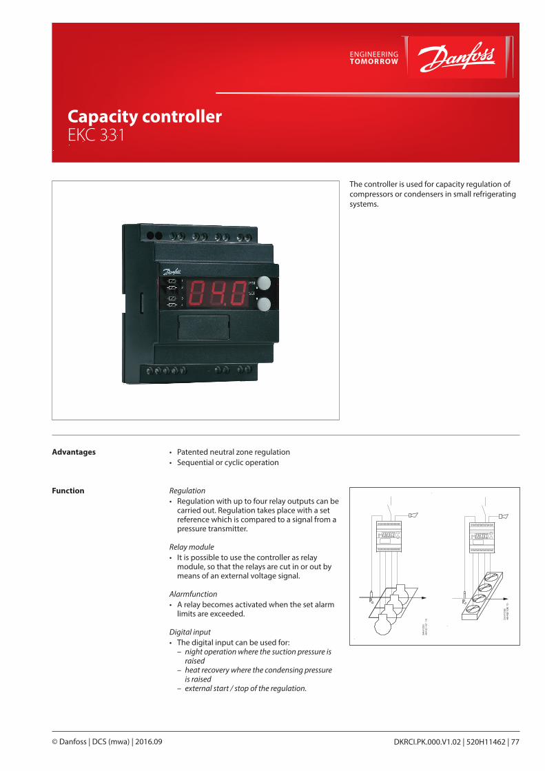
The controller is used for capacity regulation of compressors or condensers in small refrigerating systems.
Advantages • Patented neutral zone regulation• Sequential or cyclic operation
Function
Shut-off and regulating valves for Industrial Refrigeration
DKRCI.PK.000.V1.02 | 520H11462 | 77© Danfoss | DCS (mwa) | 2016.09
Capacity controller EKC 331
Regulation• Regulation with up to four relay outputs can be
carried out. Regulation takes place with a set reference which is compared to a signal from a pressure transmitter.
Relay module• It is possible to use the controller as relay
module, so that the relays are cut in or out by means of an external voltage signal.
Alarmfunction• A relay becomes activated when the set alarm
limits are exceeded.
Digital input• The digital input can be used for:
– night operation where the suction pressure is raised
– heat recovery where the condensing pressure is raised
– external start / stop of the regulation.
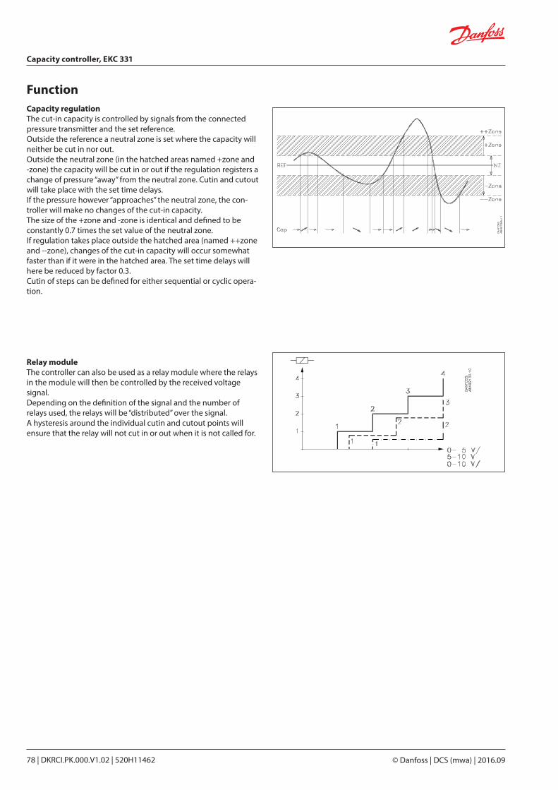
FunctionCapacity regulationThe cut-in capacity is controlled by signals from the connected pressure transmitter and the set reference.Outside the reference a neutral zone is set where the capacity will neither be cut in nor out.Outside the neutral zone (in the hatched areas named +zone and -zone) the capacity will be cut in or out if the regulation registers a change of pressure “away” from the neutral zone. Cutin and cutout will take place with the set time delays.If the pressure however “approaches” the neutral zone, the con-troller will make no changes of the cut-in capacity.The size of the +zone and -zone is identical and defined to be constantly 0.7 times the set value of the neutral zone.If regulation takes place outside the hatched area (named ++zone and --zone), changes of the cut-in capacity will occur somewhat faster than if it were in the hatched area. The set time delays will here be reduced by factor 0.3.Cutin of steps can be defined for either sequential or cyclic opera-tion.
Relay moduleThe controller can also be used as a relay module where the relays in the module will then be controlled by the received voltage signal.Depending on the definition of the signal and the number of relays used, the relays will be “distributed” over the signal.A hysteresis around the individual cutin and cutout points will ensure that the relay will not cut in or out when it is not called for.
Capacity controller, EKC 331
© Danfoss | DCS (mwa) | 2016.0978 | DKRCI.PK.000.V1.02 | 520H11462
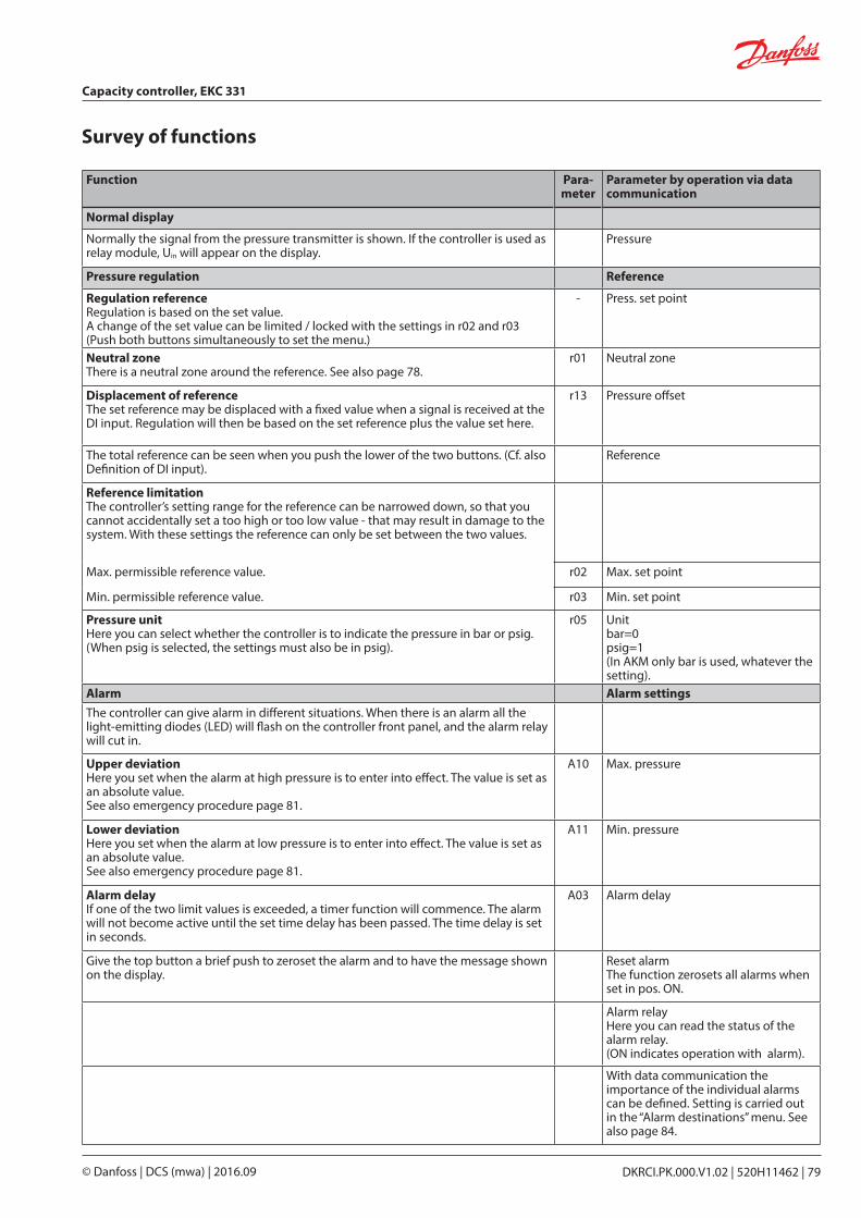
Survey of functions
Function Para- meter
Parameter by operation via data communication
Normal display
Normally the signal from the pressure transmitter is shown. If the controller is used as relay module, Uin will appear on the display.
Pressure
Pressure regulation Reference
Regulation referenceRegulation is based on the set value.A change of the set value can be limited / locked with the settings in r02 and r03(Push both buttons simultaneously to set the menu.)
- Press. set point
Neutral zoneThere is a neutral zone around the reference. See also page 78.
r01 Neutral zone
Displacement of referenceThe set reference may be displaced with a fixed value when a signal is received at the DI input. Regulation will then be based on the set reference plus the value set here.
r13 Pressure offset
The total reference can be seen when you push the lower of the two buttons. (Cf. also Definition of DI input).
Reference
Reference limitationThe controller’s setting range for the reference can be narrowed down, so that you cannot accidentally set a too high or too low value - that may result in damage to the system. With these settings the reference can only be set between the two values.
Max. permissible reference value. r02 Max. set point
Min. permissible reference value. r03 Min. set point
Pressure unitHere you can select whether the controller is to indicate the pressure in bar or psig. (When psig is selected, the settings must also be in psig).
r05 Unit bar=0psig=1(In AKM only bar is used, whatever the setting).
Alarm Alarm settingsThe controller can give alarm in different situations. When there is an alarm all the light-emitting diodes (LED) will flash on the controller front panel, and the alarm relay will cut in.
Upper deviationHere you set when the alarm at high pressure is to enter into effect. The value is set as an absolute value.See also emergency procedure page 81.
A10 Max. pressure
Lower deviationHere you set when the alarm at low pressure is to enter into effect. The value is set as an absolute value.See also emergency procedure page 81.
A11 Min. pressure
Alarm delayIf one of the two limit values is exceeded, a timer function will commence. The alarm will not become active until the set time delay has been passed. The time delay is set in seconds.
A03 Alarm delay
Give the top button a brief push to zeroset the alarm and to have the message shown on the display.
Reset alarmThe function zerosets all alarms when set in pos. ON.
Alarm relayHere you can read the status of the alarm relay.(ON indicates operation with alarm).
With data communication the importance of the individual alarms can be defined. Setting is carried out in the “Alarm destinations” menu. See also page 84.
Capacity controller, EKC 331
DKRCI.PK.000.V1.02 | 520H11462 | 79© Danfoss | DCS (mwa) | 2016.09
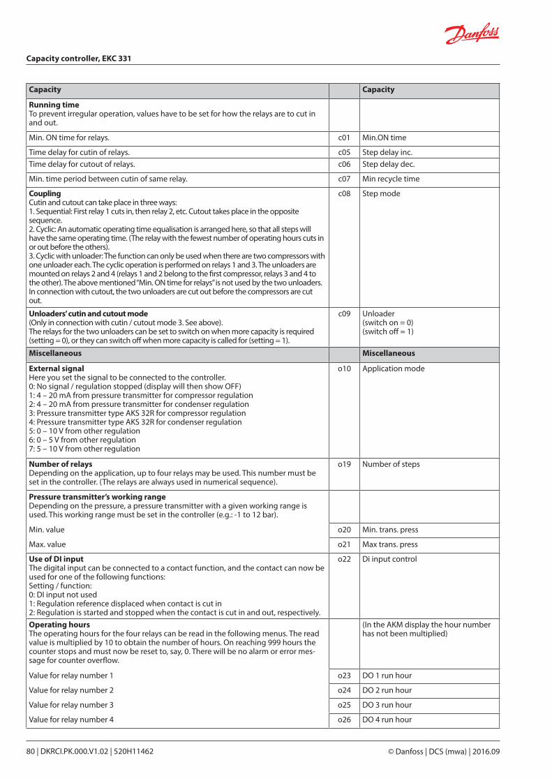
Capacity Capacity
Running timeTo prevent irregular operation, values have to be set for how the relays are to cut in and out.
Min. ON time for relays. c01 Min.ON time
Time delay for cutin of relays. c05 Step delay inc.Time delay for cutout of relays. c06 Step delay dec.
Min. time period between cutin of same relay. c07 Min recycle time
CouplingCutin and cutout can take place in three ways:1. Sequential: First relay 1 cuts in, then relay 2, etc. Cutout takes place in the opposite sequence.2. Cyclic: An automatic operating time equalisation is arranged here, so that all steps will have the same operating time. (The relay with the fewest number of operating hours cuts in or out before the others).3. Cyclic with unloader: The function can only be used when there are two compressors with one unloader each. The cyclic operation is performed on relays 1 and 3. The unloaders are mounted on relays 2 and 4 (relays 1 and 2 belong to the first compressor, relays 3 and 4 to the other). The above mentioned “Min. ON time for relays” is not used by the two unloaders.In connection with cutout, the two unloaders are cut out before the compressors are cut out.
c08 Step mode
Unloaders’ cutin and cutout mode(Only in connection with cutin / cutout mode 3. See above).The relays for the two unloaders can be set to switch on when more capacity is required (setting = 0), or they can switch off when more capacity is called for (setting = 1).
c09 Unloader (switch on = 0)(switch off = 1)
Miscellaneous Miscellaneous
External signalHere you set the signal to be connected to the controller.0: No signal / regulation stopped (display will then show OFF)1: 4 – 20 mA from pressure transmitter for compressor regulation2: 4 – 20 mA from pressure transmitter for condenser regulation3: Pressure transmitter type AKS 32R for compressor regulation4: Pressure transmitter type AKS 32R for condenser regulation5: 0 – 10 V from other regulation6: 0 – 5 V from other regulation7: 5 – 10 V from other regulation
o10 Application mode
Number of relaysDepending on the application, up to four relays may be used. This number must be set in the controller. (The relays are always used in numerical sequence).
o19 Number of steps
Pressure transmitter’s working rangeDepending on the pressure, a pressure transmitter with a given working range is used. This working range must be set in the controller (e.g.: -1 to 12 bar).
Min. value o20 Min. trans. press
Max. value o21 Max trans. press
Use of DI inputThe digital input can be connected to a contact function, and the contact can now be used for one of the following functions:Setting / function:0: DI input not used1: Regulation reference displaced when contact is cut in2: Regulation is started and stopped when the contact is cut in and out, respectively.
o22 Di input control
Operating hoursThe operating hours for the four relays can be read in the following menus. The read value is multiplied by 10 to obtain the number of hours. On reaching 999 hours the counter stops and must now be reset to, say, 0. There will be no alarm or error mes-sage for counter overflow.
(In the AKM display the hour number has not been multiplied)
Value for relay number 1 o23 DO 1 run hour
Value for relay number 2 o24 DO 2 run hour
Value for relay number 3 o25 DO 3 run hour
Value for relay number 4 o26 DO 4 run hour
Capacity controller, EKC 331
© Danfoss | DCS (mwa) | 2016.0980 | DKRCI.PK.000.V1.02 | 520H11462
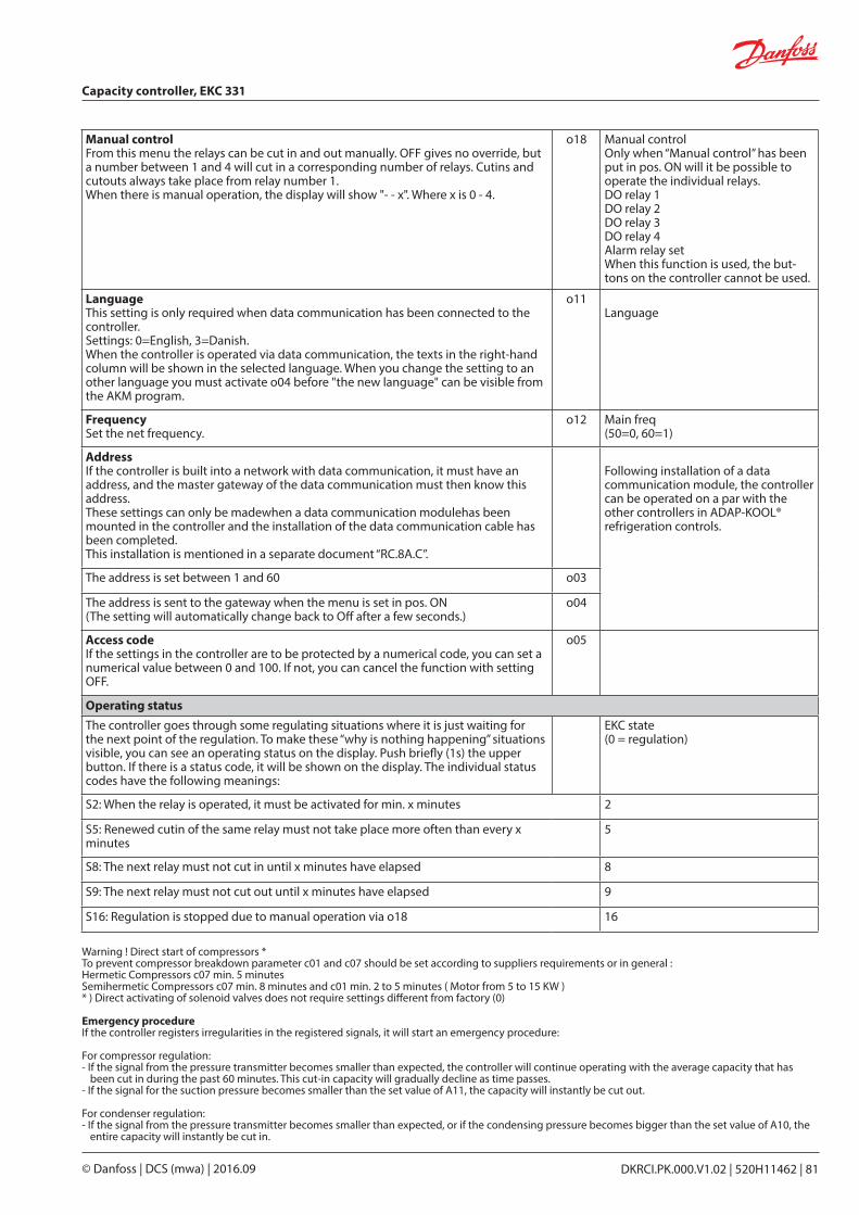
Manual controlFrom this menu the relays can be cut in and out manually. OFF gives no override, but a number between 1 and 4 will cut in a corresponding number of relays. Cutins and cutouts always take place from relay number 1.When there is manual operation, the display will show "- - x". Where x is 0 - 4.
o18 Manual controlOnly when “Manual control” has been put in pos. ON will it be possible to operate the individual relays.DO relay 1DO relay 2DO relay 3DO relay 4Alarm relay setWhen this function is used, the but-tons on the controller cannot be used.
LanguageThis setting is only required when data communication has been connected to the controller.Settings: 0=English, 3=Danish.When the controller is operated via data communication, the texts in the right-hand column will be shown in the selected language. When you change the setting to an other language you must activate o04 before "the new language" can be visible from the AKM program.
o11Language
FrequencySet the net frequency.
o12 Main freq(50=0, 60=1)
AddressIf the controller is built into a network with data communication, it must have an address, and the master gateway of the data communication must then know this address.These settings can only be madewhen a data communication modulehas been mounted in the controller and the installation of the data communication cable has been completed.This installation is mentioned in a separate document “RC.8A.C”.
Following installation of a data communication module, the controller can be operated on a par with the other controllers in ADAP-KOOL® refrigeration controls.
The address is set between 1 and 60 o03
The address is sent to the gateway when the menu is set in pos. ON(The setting will automatically change back to Off after a few seconds.)
o04
Access codeIf the settings in the controller are to be protected by a numerical code, you can set a numerical value between 0 and 100. If not, you can cancel the function with setting OFF.
o05
Operating statusThe controller goes through some regulating situations where it is just waiting for the next point of the regulation. To make these “why is nothing happening” situations visible, you can see an operating status on the display. Push briefly (1s) the upper button. If there is a status code, it will be shown on the display. The individual status codes have the following meanings:
EKC state(0 = regulation)
S2: When the relay is operated, it must be activated for min. x minutes 2
S5: Renewed cutin of the same relay must not take place more often than every x minutes
5
S8: The next relay must not cut in until x minutes have elapsed 8
S9: The next relay must not cut out until x minutes have elapsed 9
S16: Regulation is stopped due to manual operation via o18 16
Warning ! Direct start of compressors *To prevent compressor breakdown parameter c01 and c07 should be set according to suppliers requirements or in general :Hermetic Compressors c07 min. 5 minutesSemihermetic Compressors c07 min. 8 minutes and c01 min. 2 to 5 minutes ( Motor from 5 to 15 KW )* ) Direct activating of solenoid valves does not require settings different from factory (0)
Emergency procedureIf the controller registers irregularities in the registered signals, it will start an emergency procedure:
For compressor regulation:- If the signal from the pressure transmitter becomes smaller than expected, the controller will continue operating with the average capacity that has
been cut in during the past 60 minutes. This cut-in capacity will gradually decline as time passes.- If the signal for the suction pressure becomes smaller than the set value of A11, the capacity will instantly be cut out.
For condenser regulation:- If the signal from the pressure transmitter becomes smaller than expected, or if the condensing pressure becomes bigger than the set value of A10, the
entire capacity will in stantly be cut in.
Capacity controller, EKC 331
DKRCI.PK.000.V1.02 | 520H11462 | 81© Danfoss | DCS (mwa) | 2016.09
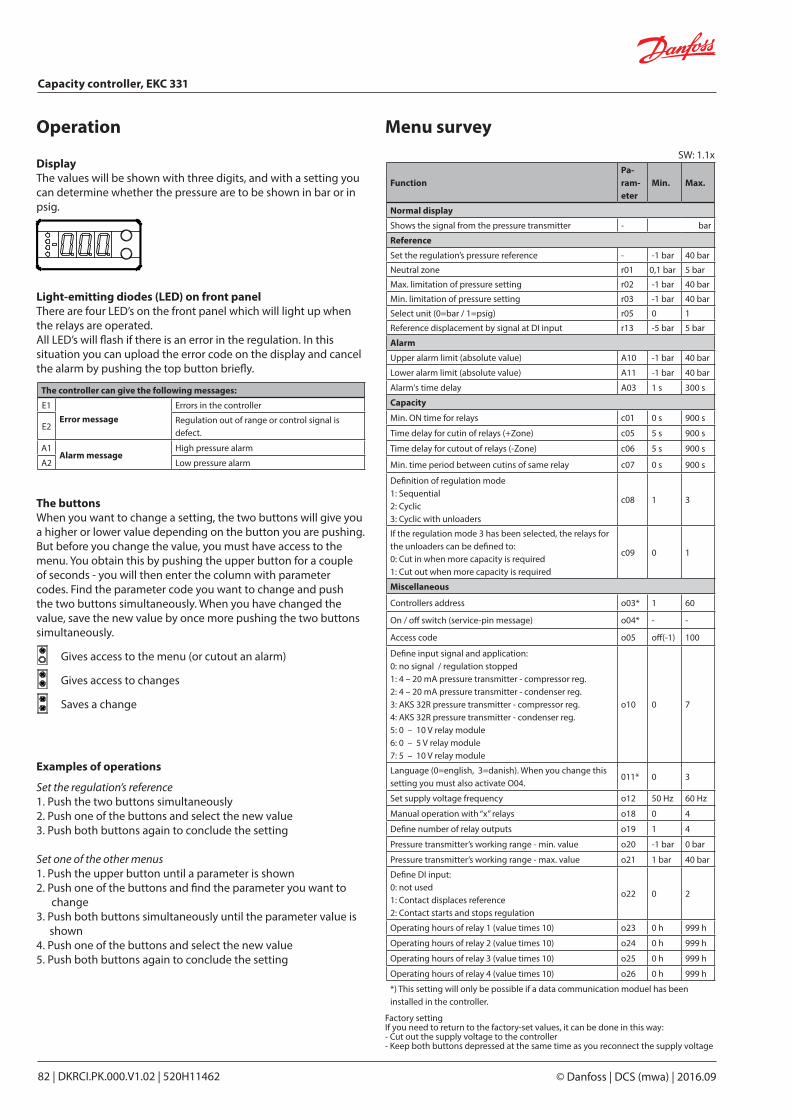
Light-emitting diodes (LED) on front panelThere are four LED’s on the front panel which will light up when the relays are operated.All LED’s will flash if there is an error in the regulation. In this situation you can upload the error code on the display and cancel the alarm by pushing the top button briefly.
DisplayThe values will be shown with three digits, and with a setting you can determine whether the pressure are to be shown in bar or in psig.
Operation
FunctionPa-ram-eter
Min. Max.
Normal display
Shows the signal from the pressure transmitter - bar
Reference
Set the regulation’s pressure reference - -1 bar 40 bar
Neutral zone r01 0,1 bar 5 bar
Max. limitation of pressure setting r02 -1 bar 40 bar
Min. limitation of pressure setting r03 -1 bar 40 bar
Select unit (0=bar / 1=psig) r05 0 1
Reference displacement by signal at DI input r13 -5 bar 5 bar
Alarm
Upper alarm limit (absolute value) A10 -1 bar 40 bar
Lower alarm limit (absolute value) A11 -1 bar 40 bar
Alarm's time delay A03 1 s 300 s
Capacity
Min. ON time for relays c01 0 s 900 s
Time delay for cutin of relays (+Zone) c05 5 s 900 s
Time delay for cutout of relays (-Zone) c06 5 s 900 s
Min. time period between cutins of same relay c07 0 s 900 s
Definition of regulation mode1: Sequential2: Cyclic3: Cyclic with unloaders
c08 1 3
If the regulation mode 3 has been selected, the relays for the unloaders can be defined to: 0: Cut in when more capacity is required1: Cut out when more capacity is required
c09 0 1
Miscellaneous
Controllers address o03* 1 60
On / off switch (service-pin message) o04* - -
Access code o05 off(-1) 100
Define input signal and application:0: no signal / regulation stopped1: 4 – 20 mA pressure transmitter - compressor reg.2: 4 – 20 mA pressure transmitter - condenser reg.3: AKS 32R pressure transmitter - compressor reg.4: AKS 32R pressure transmitter - condenser reg.5: 0 – 10 V relay module6: 0 – 5 V relay module7: 5 – 10 V relay module
o10 0 7
Language (0=english, 3=danish). When you change this setting you must also activate O04.
011* 0 3
Set supply voltage frequency o12 50 Hz 60 Hz
Manual operation with “x” relays o18 0 4
Define number of relay outputs o19 1 4
Pressure transmitter’s working range - min. value o20 -1 bar 0 bar
Pressure transmitter’s working range - max. value o21 1 bar 40 bar
Define DI input:0: not used1: Contact displaces reference2: Contact starts and stops regulation
o22 0 2
Operating hours of relay 1 (value times 10) o23 0 h 999 h
Operating hours of relay 2 (value times 10) o24 0 h 999 h
Operating hours of relay 3 (value times 10) o25 0 h 999 h
Operating hours of relay 4 (value times 10) o26 0 h 999 h
*) This setting will only be possible if a data communication moduel has been installed in the controller.
Menu survey
The controller can give the following messages:
E1Error message
Errors in the controller
E2Regulation out of range or control signal is defect.
A1Alarm message
High pressure alarm
A2 Low pressure alarm
The buttonsWhen you want to change a setting, the two buttons will give you a higher or lower value depending on the button you are pushing. But before you change the value, you must have access to the menu. You obtain this by pushing the upper button for a couple of seconds - you will then enter the column with parameter codes. Find the parameter code you want to change and push the two buttons simultaneously. When you have changed the value, save the new value by once more pushing the two buttons simultaneously.
Gives access to the menu (or cutout an alarm)
Gives access to changes
Saves a change
Examples of operations
Set the regulation’s reference1. Push the two buttons simultaneously2. Push one of the buttons and select the new value3. Push both buttons again to conclude the setting Set one of the other menus1. Push the upper button until a parameter is shown2. Push one of the buttons and find the parameter you want to
change3. Push both buttons simultaneously until the parameter value is
shown4. Push one of the buttons and select the new value5. Push both buttons again to conclude the setting
Factory settingIf you need to return to the factory-set values, it can be done in this way:- Cut out the supply voltage to the controller- Keep both buttons depressed at the same time as you recon nect the supply voltage
SW: 1.1x
Capacity controller, EKC 331
© Danfoss | DCS (mwa) | 2016.0982 | DKRCI.PK.000.V1.02 | 520H11462
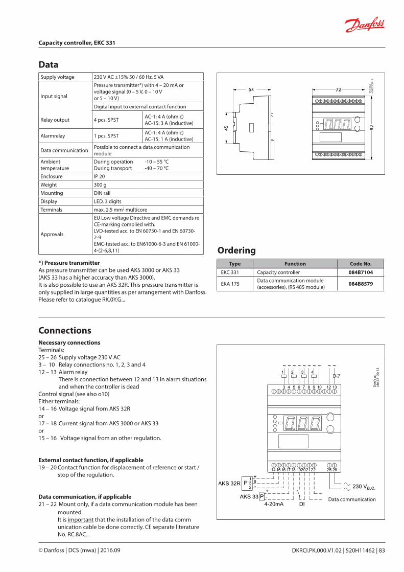
Data
OrderingType Function Code No.
EKC 331 Capacity controller 084B7104
EKA 175 Data communication module (accessories), (RS 485 module) 084B8579
Necessary connectionsTerminals:25 – 26 Supply voltage 230 V AC3 – 10 Relay connections no. 1, 2, 3 and 412 – 13 Alarm relay
There is connection between 12 and 13 in alarm situa tions and when the controller is dead
Control signal (see also o10) Either terminals:14 – 16 Voltage signal from AKS 32R or17 – 18 Current signal from AKS 3000 or AKS 33or 15 – 16 Voltage signal from an other regulation.
External contact function, if applicable19 – 20 Contact function for displacement of reference or start /
stop of the regulation.
Data communication, if applicable21 – 22 Mount only, if a data communication module has been
mounted.It is important that the installation of the data comm unication cable be done correctly. Cf. separate literature No. RC.8AC...
Connections
Supply voltage 230 V AC ±15% 50 / 60 Hz, 5 VA
Input signal
Pressure transmitter*) with 4 – 20 mA orvoltage signal (0 – 5 V, 0 – 10 V or 5 – 10 V)
Digital input to external contact function
Relay output 4 pcs. SPST AC-1: 4 A (ohmic)AC-15: 3 A (inductive)
Alarmrelay 1 pcs. SPST AC-1: 4 A (ohmic)AC-15: 1 A (inductive)
Data communication Possible to connect a data communication module
Ambient temperature
During operationDuring transport
-10 – 55 °C-40 – 70 °C
Enclosure IP 20
Weight 300 g
Mounting DIN rail
Display LED, 3 digits
Terminals max. 2,5 mm2 multicore
Approvals
EU Low voltage Directive and EMC demands re CE-marking complied with.LVD-tested acc. to EN 60730-1 and EN 60730-2-9EMC-tested acc. to EN61000-6-3 and EN 61000-4-(2-6,8,11)
Data communication
*) Pressure transmitterAs pressure transmitter can be used AKS 3000 or AKS 33(AKS 33 has a higher accuracy than AKS 3000).It is also possible to use an AKS 32R. This pressure transmitter is only supplied in large quantities as per arrangement with Danfoss.Please refer to catalogue RK.0Y.G...
Capacity controller, EKC 331
DKRCI.PK.000.V1.02 | 520H11462 | 83© Danfoss | DCS (mwa) | 2016.09
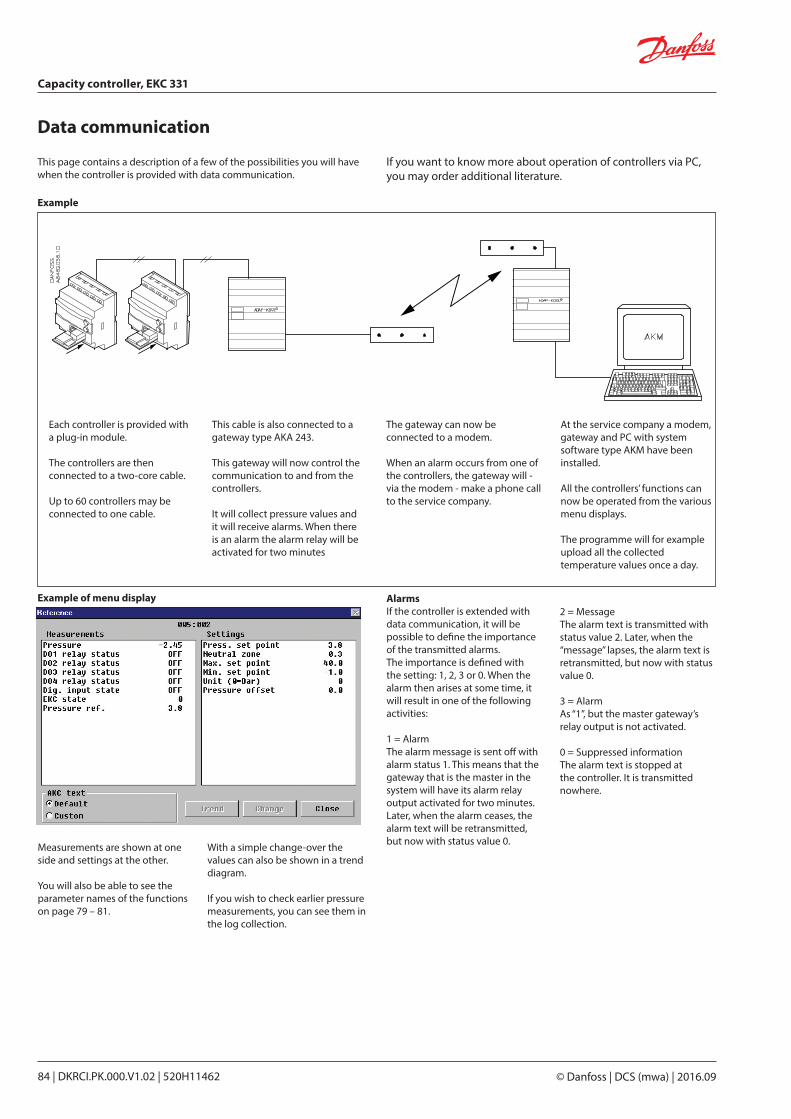
Data communication
Example
Example of menu display
If you want to know more about operation of controllers via PC, you may order additional literature.
This page contains a description of a few of the possibilities you will have when the controller is provided with data communi cation.
Each controller is provided with a plug-in module.
The controllers are then connected to a two-core cable.
Up to 60 controllers may be connected to one cable.
This cable is also connected to a gateway type AKA 243.
This gateway will now control the communication to and from the controllers.
It will collect pressure values and it will receive alarms. When there is an alarm the alarm relay will be activated for two minutes
The gateway can now be connected to a modem.
When an alarm occurs from one of the controllers, the gateway will - via the modem - make a phone call to the service company.
At the service company a modem, gateway and PC with system software type AKM have been installed.
All the controllers’ functions can now be operated from the various menu displays.
The programme will for example upload all the collected tempera ture values once a day.
AlarmsIf the controller is extended with data communication, it will be possible to define the importance of the transmitted alarms.The importance is defined with the setting: 1, 2, 3 or 0. When the alarm then arises at some time, it will result in one of the following activities:
1 = AlarmThe alarm message is sent off with alarm status 1. This means that the gateway that is the master in the system will have its alarm relay output activated for two minutes. Later, when the alarm ceases, the alarm text will be retransmitted, but now with status value 0.
2 = MessageThe alarm text is transmitted with status value 2. Later, when the “message” lapses, the alarm text is retransmitted, but now with status value 0.
3 = AlarmAs “1”, but the master gateway’s relay output is not activated.
0 = Suppressed informationThe alarm text is stopped at the controller. It is transmitted nowhere.
Measurements are shown at one side and settings at the other.
You will also be able to see the parameter names of the functions on page 79 – 81.
With a simple change-over the values can also be shown in a trend diagram.
If you wish to check earlier pressure measurements, you can see them in the log collection.
Capacity controller, EKC 331
© Danfoss | DCS (mwa) | 2016.0984 | DKRCI.PK.000.V1.02 | 520H11462

RS8CU502 | 2012.08
Contents Page
Function . . . . . . . . . . . . . . . . . . . . . . . . . . . . . . . . . . . . . . . . . . . . . . . . . . . . . . . . . . . . . . . . . . . . . . . . . . . . . . . . . . . . . . . . . 87
Advantages . . . . . . . . . . . . . . . . . . . . . . . . . . . . . . . . . . . . . . . . . . . . . . . . . . . . . . . . . . . . . . . . . . . . . . . . . . . . . . . . . . . . . . 87
Suvey of functions . . . . . . . . . . . . . . . . . . . . . . . . . . . . . . . . . . . . . . . . . . . . . . . . . . . . . . . . . . . . . . . . . . . . . . . . . . . . . . . . 90
Operation . . . . . . . . . . . . . . . . . . . . . . . . . . . . . . . . . . . . . . . . . . . . . . . . . . . . . . . . . . . . . . . . . . . . . . . . . . . . . . . . . . . . . . . . 94
Menu survey . . . . . . . . . . . . . . . . . . . . . . . . . . . . . . . . . . . . . . . . . . . . . . . . . . . . . . . . . . . . . . . . . . . . . . . . . . . . . . . . . . . . . 94
Data. . . . . . . . . . . . . . . . . . . . . . . . . . . . . . . . . . . . . . . . . . . . . . . . . . . . . . . . . . . . . . . . . . . . . . . . . . . . . . . . . . . . . . . . . . . . . . 95
Ordering . . . . . . . . . . . . . . . . . . . . . . . . . . . . . . . . . . . . . . . . . . . . . . . . . . . . . . . . . . . . . . . . . . . . . . . . . . . . . . . . . . . . . . . . . 95
Connections. . . . . . . . . . . . . . . . . . . . . . . . . . . . . . . . . . . . . . . . . . . . . . . . . . . . . . . . . . . . . . . . . . . . . . . . . . . . . . . . . . . . . . 96
Shut-off and regulating valves for Industrial Refrigeration
DKRCI.PK.000.V1.02 | 520H11462 | 85© Danfoss | DCS (mwa) | 2016.09
Capacity controller EKC 331T

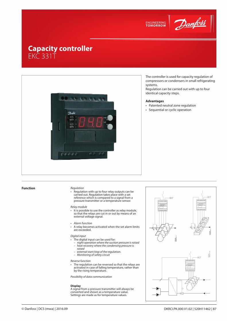
The controller is used for capacity regulation of compressors or condensers in small refrigerating systems. Regulation can be carried out with up to four identical capacity steps.
Advantages• Patented neutral zone regulation• Sequential or cyclic operation
Function Regulation• Regulation with up to four relay outputs can be
carried out. Regulation takes place with a set reference which is compared to a signal from a pressure transmitter or a temperature sensor.
Relay module• It is possible to use the controller as relay module,
so that the relays are cut in or out by means of an external voltage signal.
• Alarm function• A relay becomes activated when the set alarm limits
are exceeded.
Digital input• The digital input can be used for:
– night operation where the suction pressure is raised – heat recovery where the condensing pressure is
raised – external start/stop of the regulation. – Monitoring of safety circuit
Reverse function• The regulation can be reversed so that the relays are
activated in case of falling temperature, rather than by the rising temperature.
Possibility of data communication
DisplayA signal from a pressure transmitter will always be converted and shown as a temperature value.Settings are made as for temperature values.
Shut-off and regulating valves for Industrial Refrigeration
DKRCI.PK.000.V1.02 | 520H11462 | 87© Danfoss | DCS (mwa) | 2016.09
Capacity controller EKC 331T
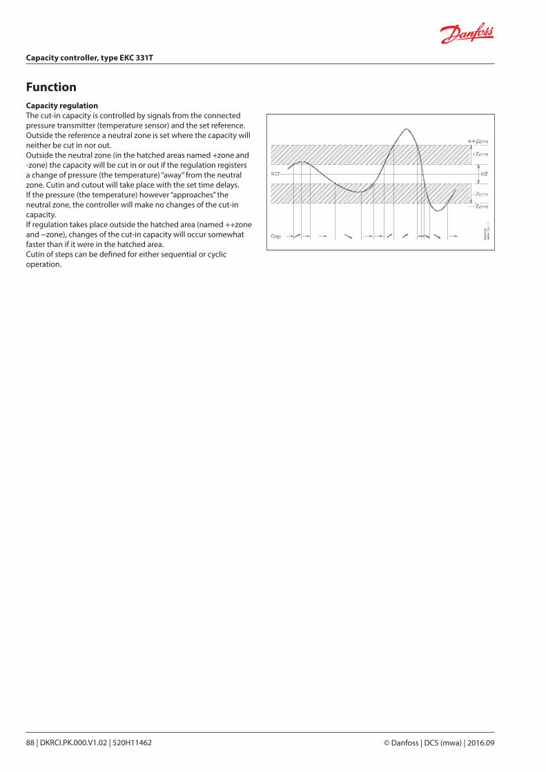
FunctionCapacity regulationThe cut-in capacity is controlled by signals from the connected pressure transmitter (temperature sensor) and the set reference.Outside the reference a neutral zone is set where the capacity will neither be cut in nor out.Outside the neutral zone (in the hatched areas named +zone and -zone) the capacity will be cut in or out if the regulation registers a change of pressure (the temperature) “away” from the neutral zone. Cutin and cutout will take place with the set time delays.If the pressure (the temperature) however “approaches” the neutral zone, the controller will make no changes of the cut-in capacity.If regulation takes place outside the hatched area (named ++zone and --zone), changes of the cut-in capacity will occur somewhat faster than if it were in the hatched area.Cutin of steps can be defined for either sequential or cyclic operation.
Capacity controller, type EKC 331T
© Danfoss | DCS (mwa) | 2016.0988 | DKRCI.PK.000.V1.02 | 520H11462
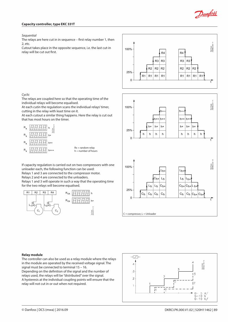
Relay moduleThe controller can also be used as a relay module where the relays in the module are operated by the received voltage signal. The signal must be connected to terminal 15 – 16.Depending on the definition of the signal and the number of relays used, the relays will be ”distributed” over the signal.A hysteresis at the individual coupling points will ensure that the relay will not cut in or out when not required.
SequentialThe relays are here cut in in sequence – first relay number 1, then 2, etc.Cutout takes place in the opposite sequence, i.e. the last cut-in relay will be cut out first.
CyclicThe relays are coupled here so that the operating time of the individual relays will become equalised.At each cutin the regulation scans the individual relays’ timer, cutting in the relay with least time on it.At each cutout a similar thing happens. Here the relay is cut out that has most hours on the timer.
If capacity regulation is carried out on two compressors with one unloader each, the following function can be used:Relays 1 and 3 are connected to the compressor motor.Relays 2 and 4 are connected to the unloaders.Relays 1 and 3 will operate in such a way that the operating time for the two relays will become equalised.
Rx = random relayh = number of hours
C = compressor, L = Unloader
Capacity controller, type EKC 331T
DKRCI.PK.000.V1.02 | 520H11462 | 89© Danfoss | DCS (mwa) | 2016.09
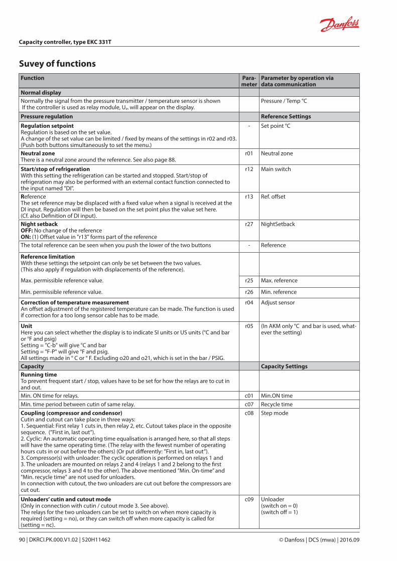
Suvey of functionsFunction Para-
meterParameter by operation via data communication
Normal displayNormally the signal from the pressure transmitter / temperature sensor is shown If the controller is used as relay module, Uin will appear on the display.
Pressure / Temp °C
Pressure regulation Reference Settings
Regulation setpointRegulation is based on the set value.A change of the set value can be limited / fixed by means of the settings in r02 and r03.(Push both buttons simultaneously to set the menu.)
- Set point °C
Neutral zoneThere is a neutral zone around the reference. See also page 88.
r01 Neutral zone
Start/stop of refrigerationWith this setting the refrigeration can be started and stopped. Start/stop of refrigeration may also be performed with an external contact function connected to the input named "DI".
r12 Main switch
ReferenceThe set reference may be displaced with a fixed value when a signal is received at the DI input. Regulation will then be based on the set point plus the value set here.(Cf. also Definition of DI input).
r13 Ref. offset
Night setbackOFF: No change of the referenceON: (1) Offset value in "r13" forms part of the reference
r27 NightSetback
The total reference can be seen when you push the lower of the two buttons - Reference
Reference limitationWith these settings the setpoint can only be set between the two values.(This also apply if regulation with displacements of the reference).
Max. permissible reference value. r25 Max. reference
Min. permissible reference value. r26 Min. reference
Correction of temperature measurementAn offset adjustment of the registered temperature can be made. The function is used if correction for a too long sensor cable has to be made.
r04 Adjust sensor
UnitHere you can select whether the display is to indicate SI units or US units (°C and bar or °F and psig)Setting = "C-b" will give °C and barSetting = "F-P" will give °F and psig.All settings made in ° C or ° F. Excluding o20 and o21, which is set in the bar / PSIG.
r05 (In AKM only °C and bar is used, what-ever the setting)
Capacity Capacity SettingsRunning timeTo prevent frequent start / stop, values have to be set for how the relays are to cut in and out.Min. ON time for relays. c01 Min.ON timeMin. time period between cutin of same relay. c07 Recycle timeCoupling (compressor and condensor)Cutin and cutout can take place in three ways:1. Sequential: First relay 1 cuts in, then relay 2, etc. Cutout takes place in the opposite sequence. (”First in, last out”).2. Cyclic: An automatic operating time equalisation is arranged here, so that all steps will have the same operating time. (The relay with the fewest number of operating hours cuts in or out before the others) (Or put differently: ”First in, last out”). 3. Compressor(s) with unloader: The cyclic operation is performed on relays 1 and 3. The unloaders are mounted on relays 2 and 4 (relays 1 and 2 belong to the first compressor, relays 3 and 4 to the other). The above mentioned ”Min. On-time” and "Min. recycle time" are not used for unloaders.In connection with cutout, the two unloaders are cut out before the compressors are cut out.
c08 Step mode
Unloaders’ cutin and cutout mode(Only in connection with cutin / cutout mode 3. See above).The relays for the two unloaders can be set to switch on when more capacity is required (setting = no), or they can switch off when more capacity is called for (setting = nc).
c09 Unloader (switch on = 0)(switch off = 1)
Capacity controller, type EKC 331T
© Danfoss | DCS (mwa) | 2016.0990 | DKRCI.PK.000.V1.02 | 520H11462
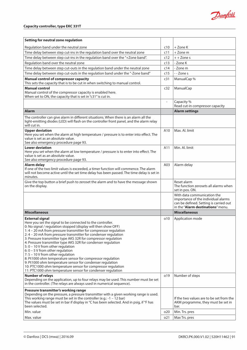
Setting for neutral zone regulation
Regulation band under the neutral zone c10 + Zone KTime delay between step cut-ins in the regulation band over the neutral zone c11 + Zone mTime delay between step cut-ins in the regulation band over the "+Zone band". c12 + + Zone sRegulation band over the neutral zone c13 - Zone KTime delay between step cut-outs in the regulation band under the neutral zone c14 - Zone mTime delay between step cut-outs in the regulation band under the "-Zone band" c15 - - Zone sManual control of compressor capacityThis sets the capacity that is to be cut in when switching to manual control.
c31 ManualCap %
Manual controlManual control of the compressor capacity is enabled here.When set to ON, the capacity that is set in “c31” is cut in.
c32 ManualCap
- Capacity %Read cut-in compressor capacity
Alarm Alarm settings
The controller can give alarm in different situations. When there is an alarm all the light-emitting diodes (LED) will flash on the controller front panel, and the alarm relay will cut in.Upper deviationHere you set when the alarm at high temperature / pressure is to enter into effect. The value is set as an absolute value.See also emergency procedure page 93.
A10 Max. Al. limit
Lower deviationHere you set when the alarm at low temperature / pressure is to enter into effect. The value is set as an absolute value.See also emergency procedure page 93.
A11 Min. Al. limit
Alarm delayIf one of the two limit values is exceeded, a timer function will commence. The alarm will not become active until the set time delay has been passed. The time delay is set in minutes.
A03 Alarm delay
Give the top button a brief push to zeroset the alarm and to have the message shown on the display.
Reset alarmThe function zerosets all alarms when set in pos. ON.With data communication the importance of the individual alarms can be defined. Setting is carried out in the “Alarm destinations” menu.
Miscellaneous Miscellaneous
External signalHere you set the signal to be connected to the controller.0: No signal / regulation stopped (display will then show OFF)1: 4 – 20 mA from pressure transmitter for compressor regulation2: 4 – 20 mA from pressure transmitter for condenser regulation3: Pressure transmitter type AKS 32R for compressor regulation4: Pressure transmitter type AKS 32R for condenser regulation5: 0 – 10 V from other regulation6: 0 – 5 V from other regulation7: 5 – 10 V from other regulation8: Pt1000 ohm temperature sensor for compressor regulation9: Pt1000 ohm temperature sensor for condenser regulation10: PTC1000 ohm temperature sensor for compressor regulation11: PTC1000 ohm temperature sensor for condenser regulation
o10 Application mode
Number of relaysDepending on the application, up to four relays may be used. This number must be set in the controller. (The relays are always used in numerical sequence).
o19 Number of steps
Pressure transmitter’s working rangeDepending on the pressure, a pressure transmitter with a given working range is used. This working range must be set in the controller (e.g.: -1 – 12 bar)The values must be set in bar if display in °C has been selected. And in psig, if °F has been selected.
If the two values are to be set from the AKM programme, they must be set in bar.
Min. value o20 Min. Trs. pres
Max. value o21 Max Trs. pres
Capacity controller, type EKC 331T
DKRCI.PK.000.V1.02 | 520H11462 | 91© Danfoss | DCS (mwa) | 2016.09
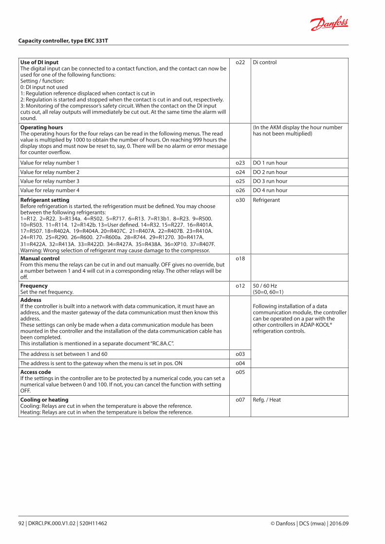
Use of DI inputThe digital input can be connected to a contact function, and the contact can now be used for one of the following functions:Setting / function:0: DI input not used1: Regulation reference displaced when contact is cut in2: Regulation is started and stopped when the contact is cut in and out, respectively.3: Monitoring of the compressor’s safety circuit. When the contact on the DI input cuts out, all relay outputs will immediately be cut out. At the same time the alarm will sound.
o22 Di control
Operating hoursThe operating hours for the four relays can be read in the following menus. The read value is multiplied by 1000 to obtain the number of hours. On reaching 999 hours the display stops and must now be reset to, say, 0. There will be no alarm or error message for counter overflow.
(In the AKM display the hour number has not been multiplied)
Value for relay number 1 o23 DO 1 run hour
Value for relay number 2 o24 DO 2 run hour
Value for relay number 3 o25 DO 3 run hour
Value for relay number 4 o26 DO 4 run hour
Refrigerant settingBefore refrigeration is started, the refrigeration must be defined. You may choose between the following refrigerants:1=R12. 2=R22. 3=R134a. 4=R502. 5=R717. 6=R13. 7=R13b1. 8=R23. 9=R500. 10=R503. 11=R114. 12=R142b. 13=User defined. 14=R32. 15=R227. 16=R401A. 17=R507. 18=R402A. 19=R404A. 20=R407C. 21=R407A. 22=R407B. 23=R410A. 24=R170. 25=R290. 26=R600. 27=R600a. 28=R744. 29=R1270. 30=R417A.31=R422A. 32=R413A. 33=R422D. 34=R427A. 35=R438A. 36=XP10. 37=R407F.Warning: Wrong selection of refrigerant may cause damage to the compressor.
o30 Refrigerant
Manual controlFrom this menu the relays can be cut in and out manually. OFF gives no override, but a number between 1 and 4 will cut in a corresponding relay. The other relays will be off.
o18
FrequencySet the net frequency.
o12 50 / 60 Hz(50=0, 60=1)
AddressIf the controller is built into a network with data communication, it must have an address, and the master gateway of the data communication must then know this address.These settings can only be made when a data communication module has been mounted in the controller and the installation of the data communication cable has been completed.This installation is mentioned in a separate document “RC.8A.C”.
Following installation of a data communication module, the controller can be operated on a par with the other controllers in ADAP-KOOL® refrigeration controls.
The address is set between 1 and 60 o03
The address is sent to the gateway when the menu is set in pos. ON o04
Access codeIf the settings in the controller are to be protected by a numerical code, you can set a numerical value between 0 and 100. If not, you can cancel the function with setting OFF.
o05
Cooling or heating Cooling: Relays are cut in when the temperature is above the reference. Heating: Relays are cut in when the temperature is below the reference.
o07 Refg. / Heat
Capacity controller, type EKC 331T
© Danfoss | DCS (mwa) | 2016.0992 | DKRCI.PK.000.V1.02 | 520H11462
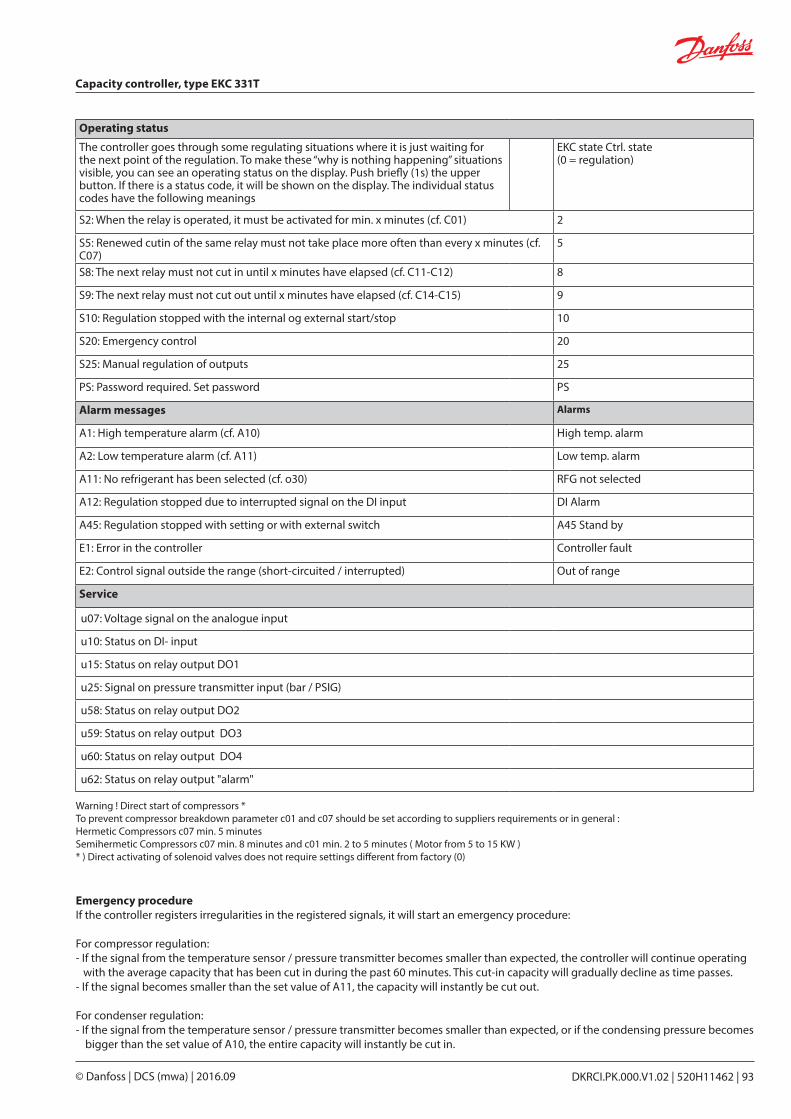
Emergency procedureIf the controller registers irregularities in the registered signals, it will start an emergency procedure:
For compressor regulation:- If the signal from the temperature sensor / pressure transmitter becomes smaller than expected, the controller will continue operating
with the average capacity that has been cut in during the past 60 minutes. This cut-in capacity will gradually decline as time passes.- If the signal becomes smaller than the set value of A11, the capacity will instantly be cut out.
For condenser regulation:- If the signal from the temperature sensor / pressure transmitter becomes smaller than expected, or if the condensing pressure becomes
bigger than the set value of A10, the entire capacity will in stantly be cut in.
Operating status
The controller goes through some regulating situations where it is just waiting for the next point of the regulation. To make these “why is nothing happening” situations visible, you can see an operating status on the display. Push briefly (1s) the upper button. If there is a status code, it will be shown on the display. The individual status codes have the following meanings
EKC state Ctrl. state(0 = regulation)
S2: When the relay is operated, it must be activated for min. x minutes (cf. C01) 2
S5: Renewed cutin of the same relay must not take place more often than every x minutes (cf. C07)
5
S8: The next relay must not cut in until x minutes have elapsed (cf. C11-C12) 8
S9: The next relay must not cut out until x minutes have elapsed (cf. C14-C15) 9
S10: Regulation stopped with the internal og external start/stop 10
S20: Emergency control 20
S25: Manual regulation of outputs 25
PS: Password required. Set password PS
Alarm messages Alarms
A1: High temperature alarm (cf. A10) High temp. alarm
A2: Low temperature alarm (cf. A11) Low temp. alarm
A11: No refrigerant has been selected (cf. o30) RFG not selected
A12: Regulation stopped due to interrupted signal on the DI input DI Alarm
A45: Regulation stopped with setting or with external switch A45 Stand by
E1: Error in the controller Controller fault
E2: Control signal outside the range (short-circuited / interrupted) Out of range
Service
u07: Voltage signal on the analogue input
u10: Status on DI- input
u15: Status on relay output DO1
u25: Signal on pressure transmitter input (bar / PSIG)
u58: Status on relay output DO2
u59: Status on relay output DO3
u60: Status on relay output DO4
u62: Status on relay output "alarm"
Warning ! Direct start of compressors *To prevent compressor breakdown parameter c01 and c07 should be set according to suppliers requirements or in general :Hermetic Compressors c07 min. 5 minutesSemihermetic Compressors c07 min. 8 minutes and c01 min. 2 to 5 minutes ( Motor from 5 to 15 KW )* ) Direct activating of solenoid valves does not require settings different from factory (0)
Capacity controller, type EKC 331T
DKRCI.PK.000.V1.02 | 520H11462 | 93© Danfoss | DCS (mwa) | 2016.09
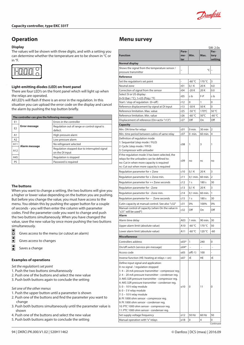
Light-emitting diodes (LED) on front panelThere are four LED’s on the front panel which will light up when the relays are operated.All LED’s will flash if there is an error in the regulation. In this situation you can upload the error code on the display and cancel the alarm by pushing the top button briefly.
DisplayThe values will be shown with three digits, and with a setting you can determine whether the temperature are to be shown in °C or in °F.
Operation Menu survey
The buttonsWhen you want to change a setting, the two buttons will give you a higher or lower value depending on the button you are pushing. But before you change the value, you must have access to the menu. You obtain this by pushing the upper button for a couple of seconds - you will then enter the column with parameter codes. Find the parameter code you want to change and push the two buttons simultaneously. When you have changed the value, save the new value by once more pushing the two buttons simultaneously.
Gives access to the menu (or cutout an alarm)
Gives access to changes
Saves a change
Examples of operations
Set the regulation’s set point1. Push the two buttons simultaneously2. Push one of the buttons and select the new value3. Push both buttons again to conclude the setting Set one of the other menus1. Push the upper button until a parameter is shown2. Push one of the buttons and find the parameter you want to
change3. Push both buttons simultaneously until the parameter value is
shown4. Push one of the buttons and select the new value5. Push both buttons again to conclude the setting
SW: 2.0x
Continued
The controller can give the following messages:
E1Error message
Errors in the controller
E2Regulation out of range or control signal is defect.
A1
Alarm message
High pressure alarm
A2 Low pressure alarm
A11 No refrigerant selected
A12Regulation stopped due to interrupted signal on the DI input
A45 Regulation is stopped
PS Password is required
FunctionPara-me-ter
Min. Max.Fac-torysetting
Normal display
Shows the signal from the temperature sensor / pressure transmitter
– °C –
Reference
Set the regulation’s set point - -60 °C 170 °C 3
Neutral zone r01 0,1 K 20 K 4.0
Correction of signal from the sensor r04 -20 K 20 K 0.0Select SI or US display: 0=SI (bar / °C). 1=US (Psig / °F)
r05 c-b F-P c-b
Start / stop of regulation (0=off) r12 0 1 0
Reference displacement by signal at DI input r13 -50 K 50 K 0
Reference limitation. Max. value r25 -50 °C 170°C 50 °C
Reference limitation. Min. value r26 -60 °C 50°C -60 °C
Displacement of reference (On=activ "r13") r27 Off On Off
Capacity
Min. ON time for relays c01 0 min. 30 min 2
Min. time period between cutins of same relay c07 0 min. 60 min. 4
Definition of regulation mode1: Sequential (step mode / FILO)2: Cyclic (step mode / FIFO)3: Compressor with unloader
c08 1 3 1
If the regulation mode 3 has been selected, the relays for the unloaders can be defined to: no: Cut in when more capacity is requirednc: Cut out when more capacity is required
c09 no nc no
Regulation parameter for + Zone c10 0,1 K 20 K 3
Regulation parameter for + Zone min. c11 0,1 min. 60 min. 2
Regulation parameter for ++ Zone seconds c12 1 s 180 s 30
Regulation parameter for - Zone c13 0,1 K 20 K 3
Regulation parameter for - Zone min. c14 0,1 min. 60 min. 1
Regulation parameter for - - Zone seconds c15 1 s 180 s 30
Cutin capacity at manual control. See also "c32" c31 0% 100% 0%Manual control of capacity (when On the value in "c31" will be used*) c32 Off On Off
Alarm
Alarm time delay A03 1 min. 90 min. 30
Upper alarm limit (absolute value) A10 -60 °C 170 °C 50
Lower alarm limit (absolute value) A11 -60 °C 120 °C -60
Miscellaneous
Controllers address o03* 1 240 0
On/off switch (service-pin message) o04* – – –
Access code o05 off(-1) 100 -
Inverse function (HE: heating at relays = on) o07 rE HE rE
Define input signal and application:0: no signal / regulation stopped1: 4 – 20 mA pressure transmitter - compressor reg.2: 4 – 20 mA pressure transmitter - condenser reg.3: AKS 32R pressure transmitter - compressor reg.4: AKS 32R pressure transmitter - condenser reg.5: 0 – 10 V relay module6: 0 – 5 V relay module7: 5 – 10 V relay module8: Pt 1000 ohm sensor - compressor reg.9: Pt 1000 ohm sensor - condenser reg.10: PTC 1000 ohm sensor - compressor reg.11: PTC 1000 ohm sensor - condenser reg.
o10 0 11 0
Set supply voltage frequency o12 50 Hz 60 Hz 50
Manual operation with “x” relays o18 0 4 0
Capacity controller, type EKC 331T
© Danfoss | DCS (mwa) | 2016.0994 | DKRCI.PK.000.V1.02 | 520H11462
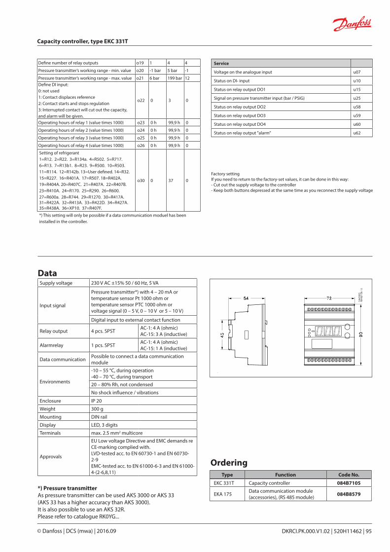
Data
Ordering
Factory settingIf you need to return to the factory-set values, it can be done in this way:- Cut out the supply voltage to the controller- Keep both buttons depressed at the same time as you recon nect the supply voltage
Supply voltage 230 V AC ±15% 50 / 60 Hz, 5 VA
Input signal
Pressure transmitter*) with 4 – 20 mA ortemperature sensor Pt 1000 ohm ortemperature sensor PTC 1000 ohm orvoltage signal (0 – 5 V, 0 – 10 V or 5 – 10 V)
Digital input to external contact function
Relay output 4 pcs. SPST AC-1: 4 A (ohmic)AC-15: 3 A (inductive)
Alarmrelay 1 pcs. SPST AC-1: 4 A (ohmic)AC-15: 1 A (inductive)
Data communication Possible to connect a data communication module
Environments
-10 – 55 °C, during operation-40 – 70 °C, during transport20 – 80% Rh, not condensed
No shock influence / vibrations
Enclosure IP 20
Weight 300 g
Mounting DIN rail
Display LED, 3 digits
Terminals max. 2.5 mm2 multicore
Approvals
EU Low voltage Directive and EMC demands re CE-marking complied with.LVD-tested acc. to EN 60730-1 and EN 60730-2-9EMC-tested acc. to EN 61000-6-3 and EN 61000-4-(2-6,8,11)
*) Pressure transmitterAs pressure transmitter can be used AKS 3000 or AKS 33(AKS 33 has a higher accuracy than AKS 3000).It is also possible to use an AKS 32R.Please refer to catalogue RK0YG...
Type Function Code No.
EKC 331T Capacity controller 084B7105
EKA 175 Data communication module (accessories), (RS 485 module) 084B8579
Define number of relay outputs o19 1 4 4
Pressure transmitter’s working range - min. value o20 -1 bar 5 bar -1
Pressure transmitter’s working range - max. value o21 6 bar 199 bar 12Define DI input:0: not used1: Contact displaces reference2: Contact starts and stops regulation3: Interrupted contact will cut out the capacity, and alarm will be given.
o22 0 3 0
Operating hours of relay 1 (value times 1000) o23 0 h 99,9 h 0
Operating hours of relay 2 (value times 1000) o24 0 h 99,9 h 0
Operating hours of relay 3 (value times 1000) o25 0 h 99,9 h 0
Operating hours of relay 4 (value times 1000) o26 0 h 99,9 h 0
Setting of refrigerant1=R12. 2=R22. 3=R134a. 4=R502. 5=R717. 6=R13. 7=R13b1. 8=R23. 9=R500. 10=R503. 11=R114. 12=R142b. 13=User defined. 14=R32. 15=R227. 16=R401A. 17=R507. 18=R402A. 19=R404A. 20=R407C. 21=R407A. 22=R407B. 23=R410A. 24=R170. 25=R290. 26=R600. 27=R600a. 28=R744. 29=R1270. 30=R417A. 31=R422A. 32=R413A. 33=R422D. 34=R427A. 35=R438A. 36=XP10. 37=R407F.
o30 0 37 0
*) This setting will only be possible if a data communication moduel has been installed in the controller.
Service
Voltage on the analogue input u07
Status on DI- input u10
Status on relay output DO1 u15
Signal on pressure transmitter input (bar / PSIG) u25
Status on relay output DO2 u58
Status on relay output DO3 u59
Status on relay output DO4 u60
Status on relay output "alarm" u62
Capacity controller, type EKC 331T
DKRCI.PK.000.V1.02 | 520H11462 | 95© Danfoss | DCS (mwa) | 2016.09
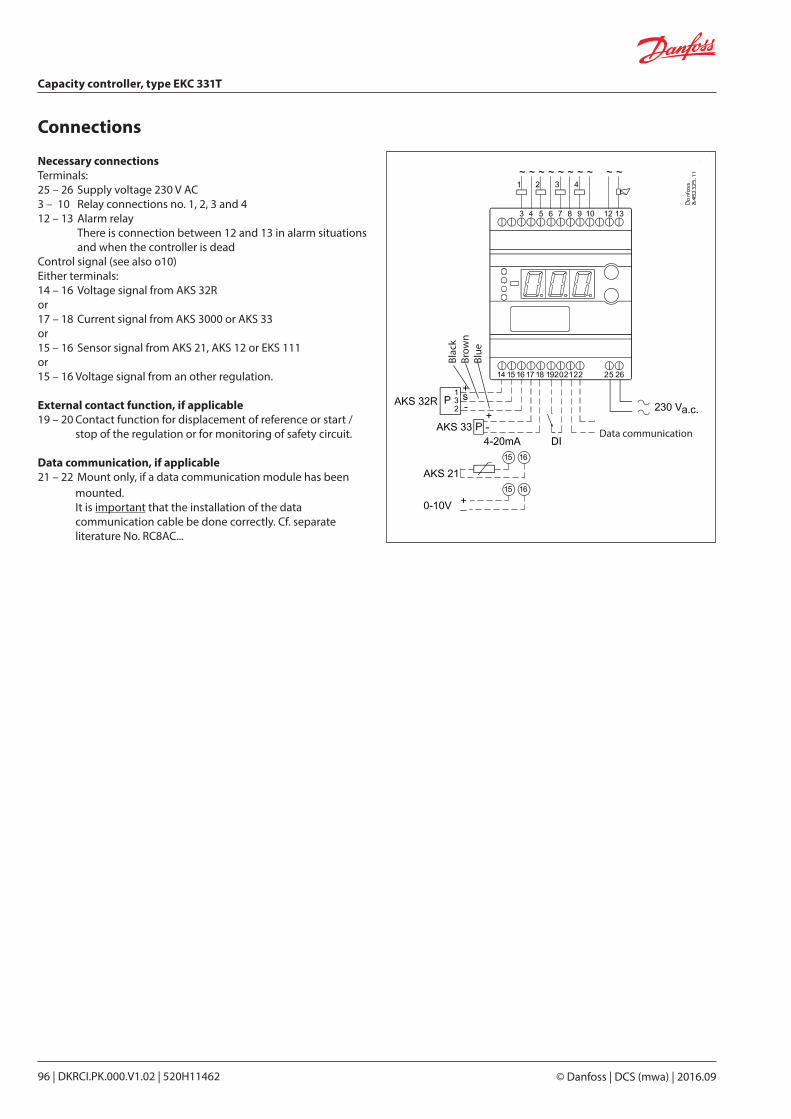
Necessary connectionsTerminals:25 – 26 Supply voltage 230 V AC3 – 10 Relay connections no. 1, 2, 3 and 412 – 13 Alarm relay
There is connection between 12 and 13 in alarm situa tions and when the controller is dead
Control signal (see also o10) Either terminals:14 – 16 Voltage signal from AKS 32R or17 – 18 Current signal from AKS 3000 or AKS 33or 15 – 16 Sensor signal from AKS 21, AKS 12 or EKS 111or15 – 16 Voltage signal from an other regulation.
External contact function, if applicable19 – 20 Contact function for displacement of reference or start /
stop of the regulation or for monitoring of safety circuit.
Data communication, if applicable21 – 22 Mount only, if a data communication module has been
mounted.It is important that the installation of the data communication cable be done correctly. Cf. separate literature No. RC8AC...
Connections
Data communication
Blac
kBr
own
Blue
Capacity controller, type EKC 331T
© Danfoss | DCS (mwa) | 2016.0996 | DKRCI.PK.000.V1.02 | 520H11462
RK0YG602_Pages 184-185 | 2015.03
Shut-off and regulating valves for Industrial Refrigeration
DKRCI.PK.000.V1.02 | 520H11462 | 97© Danfoss | DCS (mwa) | 2016.09
Temperature sensors AKS 11, AKS 12, AKS 21, AK-HS 1000
Contents Page
Technical data and ordering. . . . . . . . . . . . . . . . . . . . . . . . . . . . . . . . . . . . . . . . . . . . . . . . . . . . . . . . . . . . . . . . . . . . . . . 99
Functional description . . . . . . . . . . . . . . . . . . . . . . . . . . . . . . . . . . . . . . . . . . . . . . . . . . . . . . . . . . . . . . . . . . . . . . . . . . . . 99
Dimensioning . . . . . . . . . . . . . . . . . . . . . . . . . . . . . . . . . . . . . . . . . . . . . . . . . . . . . . . . . . . . . . . . . . . . . . . . . . . . . . . . . . . 100


These sensors are recommended for accurate temperature measurement in applications such as superheating, food safety logs, and other important temperature measurement applications.
Functional descriptionThe sensor unit consists of a platinum element the resistance value of which changes proportionally with the temperature. Pt 1000 ohm sensor (1000 ohm at 0 °C).The sensors are adjusted and meet the tolerance requirements of EN 60751 Class B.
Type DescriptionTemperature
range [°C]
Sensor / sensor body
Connection /cable Enclosure
Time constant
[s]
Cable length
[m]Qty Code
AKS 11 *)Surface and duct sensor for control and monitoring
-50 – 100 Top: PPO (Noryl) Bottom: stainless steel
PVC cable, 2 x 0.2 mm2 IP 67
3 1)10 2)35 3)
3.5 m 1 084N0003
3.5 m + AMP 110 084N0050
5.5 m 1 084N0005
5.5 m + AMP 70 084N0051
8.5 m 1 084N0008
8.5 m + AMP 50 084N0052
AKS 12 Air temperature sensor for monitoring -40 – 100 18⁄8 stainless steel PVC cable
2 x 0.22 mm2 IP 67 15 2)
1.5 m1 084N0036
30 084N0035
3.5 m 30 084N0039
5.5 m 30 084N0038
5.5 m + AMP 30 084N0037
AKS 21A **)Surface sensor with clip -70 – 180
18⁄8 stainless steelFire-resistant silicone rubber cable, 2 x 0.2 mm2
IP 676 1)
14 2)
35 3)
2.5 m 1 084N2007
5.0 m 1 084N2008
Surface sensor with shielded cable and clip -70 – 180 2.0 m 1 084N2024
AKS 21M Multipurpose sensor -70 – 180 2.5 m 1 084N2003
AKS 21WImmersion sensor with cable and sensor pocket, welded version
-70 – 180
Immersion sensor, 18⁄8 stainless steel tube Fire-resistant
silicone rubber cable, 2 x 0.2 mm2
IP 56 18 1) 2.5 m 1 084N2017Weld nipple: 18⁄8 stainless steel
Thread nipple: free cutting steel
AK-HS 1000 Product sensor for HACCP logging -30 – 50 ABS and PC PVC cable
2 x 0.25 mm2 IP 54 180-900 3) 5.5 m 1 084N1007
1) Agitated liquid. 2) Clamped to pipe. 3) Air 4 m/s.
*) Recommended for measuring superheat**) Recommended for hot gas systems
Technical data and ordering
Shut-off and regulating valves for Industrial Refrigeration
DKRCI.PK.000.V1.02 | 520H11462 | 99© Danfoss | DCS (mwa) | 2016.09
Temperature sensors AKS 11, AKS 12, AKS 21, AK-HS 1000
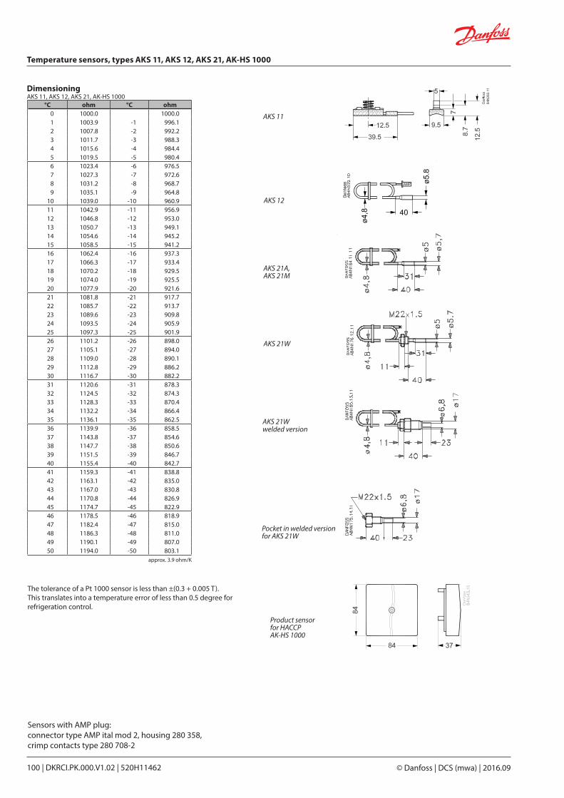
DimensioningAKS 11, AKS 12, AKS 21, AK-HS 1000
AKS 11
AKS 21A, AKS 21M
AKS 21W welded version
AKS 21W
Pocket in welded version for AKS 21W
AKS 12
approx. 3.9 ohm/K
°C ohm °C ohm 0 1000.0 1000.0 1 1003.9 -1 996.12 1007.8 -2 992.23 1011.7 -3 988.34 1015.6 -4 984.45 1019.5 -5 980.4 6 1023.4 -6 976.57 1027.3 -7 972.68 1031.2 -8 968.79 1035.1 -9 964.8
10 1039.0 -10 960.9 11 1042.9 -11 956.912 1046.8 -12 953.013 1050.7 -13 949.114 1054.6 -14 945.215 1058.5 -15 941.2 16 1062.4 -16 937.317 1066.3 -17 933.418 1070.2 -18 929.519 1074.0 -19 925.520 1077.9 -20 921.6 21 1081.8 -21 917.722 1085.7 -22 913.723 1089.6 -23 909.824 1093.5 -24 905.925 1097.3 -25 901.9 26 1101.2 -26 898.0 27 1105.1 -27 894.028 1109.0 -28 890.129 1112.8 -29 886.230 1116.7 -30 882.2 31 1120.6 -31 878.3 32 1124.5 -32 874.333 1128.3 -33 870.434 1132.2 -34 866.435 1136.1 -35 862.5 36 1139.9 -36 858.537 1143.8 -37 854.638 1147.7 -38 850.639 1151.5 -39 846.740 1155.4 -40 842.7 41 1159.3 -41 838.8 42 1163.1 -42 835.0 43 1167.0 -43 830.8 44 1170.8 -44 826.9 45 1174.7 -45 822.9 46 1178.5 -46 818.9 47 1182.4 -47 815.0 48 1186.3 -48 811.0 49 1190.1 -49 807.0 50 1194.0 -50 803.1
Sensors with AMP plug:connector type AMP ital mod 2, housing 280 358,crimp contacts type 280 708-2
The tolerance of a Pt 1000 sensor is less than ±(0.3 + 0.005 T).This translates into a temperature error of less than 0.5 degree for refrigeration control.
Product sensor for HACCPAK-HS 1000
Temperature sensors, types AKS 11, AKS 12, AKS 21, AK-HS 1000
© Danfoss | DCS (mwa) | 2016.09100 | DKRCI.PK.000.V1.02 | 520H11462

Contents Page
Advantages . . . . . . . . . . . . . . . . . . . . . . . . . . . . . . . . . . . . . . . . . . . . . . . . . . . . . . . . . . . . . . . . . . . . . . . . . . . . . . . . . . . . . 103
Output signal. . . . . . . . . . . . . . . . . . . . . . . . . . . . . . . . . . . . . . . . . . . . . . . . . . . . . . . . . . . . . . . . . . . . . . . . . . . . . . . . . . . . 104
Ordering data . . . . . . . . . . . . . . . . . . . . . . . . . . . . . . . . . . . . . . . . . . . . . . . . . . . . . . . . . . . . . . . . . . . . . . . . . . . . . . . . . . . 104
Dimensions and weights . . . . . . . . . . . . . . . . . . . . . . . . . . . . . . . . . . . . . . . . . . . . . . . . . . . . . . . . . . . . . . . . . . . . . . . . . 106
Shut-off and regulating valves for Industrial Refrigeration
DKRCI.PK.000.V1.02 | 520H11462 | 101© Danfoss | DCS (mwa) | 2016.09
Pressure transmitters AKS 32, AKS 33, AKS 32R, AKS 2050
RK0YG602_pages 190-192 | 2015.03

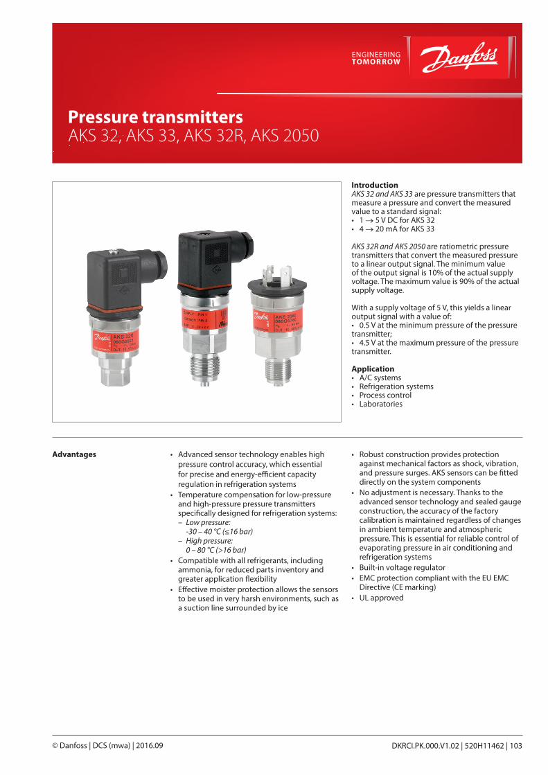
IntroductionAKS 32 and AKS 33 are pressure transmitters that measure a pressure and convert the measured value to a standard signal:• 1 → 5 V DC for AKS 32• 4 → 20 mA for AKS 33
AKS 32R and AKS 2050 are ratiometric pressure transmitters that convert the measured pressure to a linear output signal. The minimum value of the output signal is 10% of the actual supply voltage. The maximum value is 90% of the actual supply voltage.
With a supply voltage of 5 V, this yields a linear output signal with a value of:• 0.5 V at the minimum pressure of the pressure transmitter;• 4.5 V at the maximum pressure of the pressure transmitter.
Application • A/C systems• Refrigeration systems• Process control• Laboratories
Advantages • Advanced sensor technology enables high pressure control accuracy, which essential for precise and energy-efficient capacity regulation in refrigeration systems
• Temperature compensation for low-pressure and high-pressure pressure transmitters specifically designed for refrigeration systems:
– Low pressure: -30 – 40 °C (≤16 bar)
– High pressure: 0 – 80 °C (>16 bar)
• Compatible with all refrigerants, including ammonia, for reduced parts inventory and greater application flexibility
• Effective moister protection allows the sensors to be used in very harsh environments, such as a suction line surrounded by ice
• Robust construction provides protection against mechanical factors as shock, vibration, and pressure surges. AKS sensors can be fitted directly on the system components
• No adjustment is necessary. Thanks to the advanced sensor technology and sealed gauge construction, the accuracy of the factory calibration is maintained regardless of changes in ambient temperature and atmospheric pressure. This is essential for reliable control of evaporating pressure in air conditioning and refrigeration systems
• Built-in voltage regulator• EMC protection compliant with the EU EMC
Directive (CE marking)• UL approved
Shut-off and regulating valves for Industrial Refrigeration
DKRCI.PK.000.V1.02 | 520H11462 | 103© Danfoss | DCS (mwa) | 2016.09
Pressure transmitters AKS 32, AKS 33, AKS 32R, AKS 2050
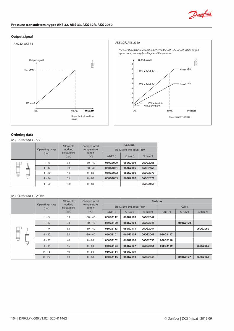
Output signal
The plot shows the relationship between the AKS 32R (or AKS 2050) output signal from , the supply voltage and the pressure.
Vsupply = supply voltage
AKS 32R, AKS 2050AKS 32, AKS 33
Upper limit of working range
Ordering dataAKS 32, version 1 – 5 V
Operating range [bar]
Allowable working
pressure PB [bar]
Compensated temperature
range [°C]
Code no.
EN 175301-803 plug Pg 9
1⁄4 NPT 1) G 3⁄8 A 2) 1⁄4 flare 3)
-1 – 6 33 -30 – 40 060G2000 060G2004 060G2068
-1 – 12 33 -30 – 40 060G2001 060G2005 060G2069
-1 – 20 40 0 – 80 060G2002 060G2006 060G2070
-1 – 34 55 0 – 80 060G2003 060G2007 060G2071
-1 – 50 100 0 – 80 060G2155
AKS 33, version 4 – 20 mA
Operating range [bar]
Allowable working
pressure PB [bar]
Compensated temperature
range [°C]
Code no.
EN 175301-803 plug Pg 9 Cable
1⁄4 NPT 1) G 3⁄8 A 2) 1⁄4 flare 3) 1⁄4 NPT 1) G 3⁄8 A 2) 1⁄4 flare 3)
-1 – 5 33 -30 – 40 060G2112 060G2108 060G2047
-1 – 6 33 -30 – 40 060G2100 060G2104 060G2048 060G2120
-1 – 9 33 -30 – 40 060G2113 060G2111 060G2044 060G2062
-1 – 12 33 -30 – 40 060G2101 060G2105 060G2049 060G2117
-1 – 20 40 0 – 80 060G2102 060G2106 060G2050 060G2118
-1 – 34 55 0 – 80 060G2103 060G2107 060G2051 060G2119 060G2065
0 – 16 40 0 – 80 060G2114 060G2109
0 – 25 40 0 – 80 060G2115 060G2110 060G2045 060G2127 060G2067
Pressure transmitters, types AKS 32, AKS 33, AKS 32R, AKS 2050
© Danfoss | DCS (mwa) | 2016.09104 | DKRCI.PK.000.V1.02 | 520H11462
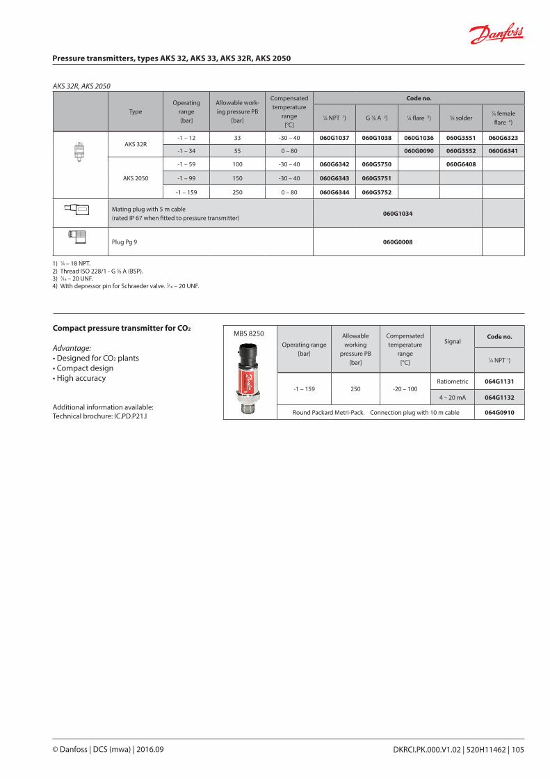
Operating range [bar]
Allowable working
pressure PB [bar]
Compensated temperature
range [°C]
SignalCode no.
1⁄4 NPT 1)
-1 – 159 250 -20 – 100Ratiometric 064G1131
4 – 20 mA 064G1132
Round Packard Metri-Pack. Connection plug with 10 m cable 064G0910
AKS 32R, AKS 2050
1) 1⁄4 – 18 NPT. 2) Thread ISO 228/1 - G 3⁄8 A (BSP).3) 7⁄16 – 20 UNF.4) With depressor pin for Schraeder valve. 7⁄16 – 20 UNF.
TypeOperating
range [bar]
Allowable work-ing pressure PB
[bar]
Compensated temperature
range [°C]
Code no.
1⁄4 NPT 1) G 3⁄8 A 2) 1⁄4 flare 3) 3⁄8 solder1⁄4 female
flare 4)
AKS 32R-1 – 12 33 -30 – 40 060G1037 060G1038 060G1036 060G3551 060G6323
-1 – 34 55 0 – 80 060G0090 060G3552 060G6341
AKS 2050
-1 – 59 100 -30 – 40 060G6342 060G5750 060G6408
-1 – 99 150 -30 – 40 060G6343 060G5751
-1 – 159 250 0 – 80 060G6344 060G5752
Mating plug with 5 m cable(rated IP 67 when fitted to pressure transmitter)
060G1034
Plug Pg 9 060G0008
MBS 8250Compact pressure transmitter for CO2
Advantage:• Designed for CO2 plants• Compact design• High accuracy
Additional information available:Technical brochure: IC.PD.P21.I
Pressure transmitters, types AKS 32, AKS 33, AKS 32R, AKS 2050
DKRCI.PK.000.V1.02 | 520H11462 | 105© Danfoss | DCS (mwa) | 2016.09
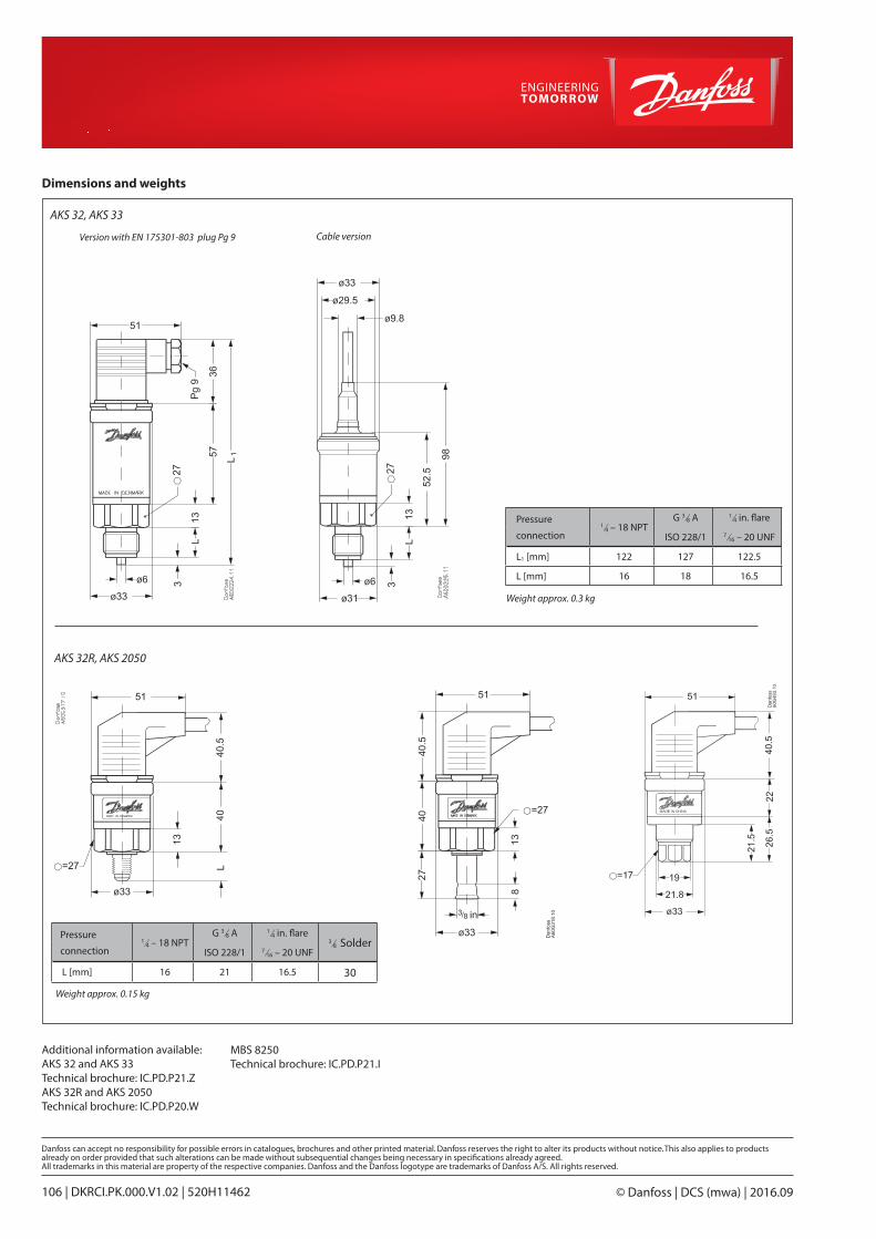
Cable versionVersion with EN 175301-803 plug Pg 9
Weight approx. 0.3 kg
Dimensions and weights
AKS 32R, AKS 2050
Additional information available:AKS 32 and AKS 33Technical brochure: IC.PD.P21.ZAKS 32R and AKS 2050Technical brochure: IC.PD.P20.W
AKS 32, AKS 33
Pressure
connection1⁄4 – 18 NPT
G 3⁄8 A 1⁄4 in. flare
ISO 228/1 7⁄16 – 20 UNF
L1 [mm] 122 127 122.5
L [mm] 16 18 16.5
Weight approx. 0.15 kg
Pressure
connection1⁄4 – 18 NPT
G 3⁄8 A 1⁄4 in. flare3⁄8 Solder
ISO 228/1 7⁄16 – 20 UNF
L [mm] 16 21 16.5 30
MBS 8250Technical brochure: IC.PD.P21.I
© Danfoss | DCS (mwa) | 2016.09106 | DKRCI.PK.000.V1.02 | 520H11462