Catalogue June 2011 - Schneider Electric Automatyka przemyslowa/Lampki i... · Catalogue June 2011...
23
Catalogue June 2011 Harmony XB4/XB5 control and signalling units for harsh environments
Transcript of Catalogue June 2011 - Schneider Electric Automatyka przemyslowa/Lampki i... · Catalogue June 2011...

Catalogue
June 2011
Harmony XB4/XB5 control and signalling units for harsh environments

All technical information about products listed in this catalogue are now available on:www.schneider-electric.comBrowse the “product data sheet” to check out :
characteristics,dimensions,curves, ...and also the links to the user guides and the CAD fi les.
pppp
1 From the home page, type the model number* into the “Search” box.
2 Under ”All” tab, click the model number that interests you.
* type the model number without any blank, replace “p” by “*”

U
C
t1
G
Rt'1t2 t'2
U
C
t1
G
Rt'1t2 t'2
89,5
80
8222,5
78
3 The product data sheet displays.
You can get this information in one single pdf fi le.
Discover this productCharacteriticsFunctionsConnectionDimensionsDownload & Documents
Other productsHelp me to choose
AccessoriesPlugSockets
ppppp
p
pp
Example : Zelio Time data sheet
Example : Zelio Time data sheet
Example : Zelio Time data sheet


Harmony XB4/XB5 provides a complete control & signalling solution for harsh environmentsApplications today demand high performance in harsh environments. Outdoor use of machinery, high pressure cleaning and exposure to extreme temperature conditions are common and can adversely affect the performance of devices for human machine interfacing.
1
Designed to performComplete offer for all applications in harsh environments
Built on proven qualityA robust and rugged design with high performance and long life in use
Common accessories andcomplementary functionsProven quality and worldwide availability
Make the most of your energy
ContentsHarmony benefits for harsh environments ................................................................................... 1 to 3
Control and signalling units ø 22Harmony XB4 metal ........................................................................................................................... 4 to 9Harmony XB5 plastic ..................................................................................................................... 10 to 15Harmony XB4 & XB5 common components ............................................................................ 16 to 17

> Rugged design and protection• External boot to prevent ingress of water and dustinto the head as well as the panel• Large diameter head for operation by gloved hand.
> Unique and innovative marking system• Clear marking, with high contrast symbols or text• UV resistant for high performance and long life• Marking is customizable to your application.
2
IP66IP69K performance
100%customizable head marking
Designed to performHarmony for harsh Environments is designed for the most difficult of applications. As the market leader in control and signalling, Schneider Electric has the knowledge and experience to meet your exacting demands.

> Complete rangeThese pushbuttons are available in XB4 metal bodied and XB5 plastic bodied versions, and both are fitted with an external boot to protect against liquid and dust ingress into the head itself.
Harmony XB4
Harmony XB5
3
More than
200 millionproducts in service
Built on proven qualityHarmony for harsh environments perfectly complements the world leading XB4 and XB5 families with over 10 years of proven qualityand performance.
Common accessories Uses fixing collars and contact blocks from the XB4 and XB5families – over 10 years of proven quality and performance.
> ... and complementary functionsto complete your solution• Booted pushbuttons, selector switches, key operated switches • Emergency Stop devices• Illuminated functions for status indication• Protective guard to limit accidental operation• Protective boot for high dust environments to limit contact block pollution.
100%Worldwide availability
Industrial vehicule MiningOutdoor machinery Marine

4
Pushbuttons with integrated bellowShape of head Colour of push Symbol Reference Weight
kgHeads only, Ø 37 mm (IP 66 + IP 69K) without marking
Flush White – ZB4 BC180 0.036
Black – ZB4 BC280 0.036
Green – ZB4 BC380 0.036
Red – ZB4 BC480 0.036
Yellow – ZB4 BC580 0.036
Blue – ZB4 BC680 0.036
Grey – ZB4 BC780 0.036
Light blue – ZB4 BC980 0.036
Heads only, Ø 37 mm (IP 66 + IP 69K) with marking (1)Flush Black
Bell ZB4 BC28001 0.036
0 ZB4 BC28021 0.036
White I ZB4 BC18023 0.036
Red 0 ZB4 BC48021 0.036
Green I ZB4 BC38023 0.036
AccessoriesDescription Function Reference Weight
kgProtective guard in plastic Protection against accidental
operationZBZ 1902 (2) 0.010
Boot for contact blockZBE 10p, ZBE 10p3 andZBE 50p (3)
Protection against liquid anddust ingress
ZBZ 60 r 0.098
(1) Heads are fi xed relative to the position of the contact blocks:
- contact blocks are normally used in the “vertical” position.
- to mount the contact block in the “horizontal” position, it is necessary to order an alternative head with the symbol rotated by 90°. Please add the suffi x «RA» in the end of the references for alternative heads of your choice.Example: ZB4 BC28001 becomes ZB4 BC28001RA.
(2) For heads with the RA suffi x (ZB4 BCppppRA) used with a guard, it is necessary to order the dedicated guard ZBZ 1902RA.(3) Restriction for use: refer to the product instruction sheet on www.schneider-electric.com.
Other versions Customization with other texts or symbolsPlease consult our Customer Care Centre.
Control and signalling units Ø 22Harmony® XB4 metalPushbuttons and switches for harsh environmentSpring return pushbuttons, unmarked or with marking
References
r Available: 3rd quarter 2011.
Assembly of other products using body/contact assemblies: see page 16
ZB4 BC580
PF1
0120
2
ZB4 BC28001
PF1
0121
3
Contact + ZB4 BC28001
Contact + ZB4 BC28001RA
PF1
0120
8P
F101
209
ZBZ 60
PF1
0121
4
ZBZ 1902
PF1
0120
3

5
Pushbuttons with silicone booted headScrew clamp terminal connections (Schneider Electric anti-retightening system)Shape of head
Type of push
Type of contact Colour of push
Reference Weight
kg
N/O N/C
Complete units (IP 66 + IP 69K) Booted,
clear silicone(colour of push unobscured)
1 – Black XB4 BP21(ZB4 BZ101 + ZB4 BP2)
0.082
Green XB4 BP31(ZB4 BZ101 + ZB4 BP3)
0.082
Yellow XB4 BP51(ZB4 BZ101 + ZB4 BP5)
0.082
Blue XB4 BP61(ZB4 BZ101 + ZB4 BP6)
0.082
– 1 Red XB4 BP42(ZB4 BZ102 + ZB4 BP4)
0.082
Silicone booted heads only, with increased protection (IP 66 + IP 69K)Flush Clear boot (1)
For insertionof protectedlegend withinhead (2)
White ZB4 BP18 0.034Green ZB4 BP38 0.034Red ZB4 BP48 0.034Yellow ZB4 BP58 0.034Blue ZB4 BP68 0.034
Projecting Clear boot (1) White ZB4 BP1 0.031Black ZB4 BP2 0.031Green ZB4 BP3 0.031Red ZB4 BP4 0.031Yellow ZB4 BP5 0.031Blue ZB4 BP6 0.031
Silicone booted heads only, standard for mounting with legend holder (IP 66)Flush Coloured boot White ZB4 BP1S 0.034
Black ZB4 BP2S 0.034Green ZB4 BP3S 0.034Red ZB4 BP4S 0.034Yellow ZB4 BP5S 0.034Blue ZB4 BP6S 0.034
Clear membraneFor insertionof protectedlegend withinhead (2)
White ZB4 BP183 0.026Green ZB4 BP383 0.026Red ZB4 BP483 0.026Yellow ZB4 BP583 0.026Blue ZB4 BP683 0.026
Transparent boots for pushbuttonsDescription For use with pushbutton types Sold in
lots ofUnit reference
Weight kg
Single boots (1) Flush with circular head 10 ZBP A 0.002Projecting with circular head and push-push version
10 ZBP 0 0.002
Flush or projecting with circular headfor food industry applications
10 ZBP 0A 0.002
Coloured bootsDescription Colour For use with Sold in
lots ofUnit reference
Weightkg
Coloured boots (3)
Black ZB4 BP2S 10 ZBP 012 0.003Green ZB4 BP3S 10 ZBP 013 0.003Red ZB4 BP4S 10 ZBP 014 0.003Yellow ZB4 BP5S 10 ZBP 015 0.003Blue ZB4 BP6S 10 ZBP 016 0.003
Heads with black metal bezelTo order, add a fi gure 7 to the references selected from above. Example: ZB4 BP18 becomes ZB4 BP187.(1) Permissible panel thickness 1 to 5 mm, cannot be used with legend holders.(2) To order a legend for insertion within the head, please consult our site www.schneider-electric.com.(3) Can be replaced without dismantling the head.
ZB4 BP183
1094
95
ZB4 BP183
1094
95
Control and signalling units Ø 22Harmony® XB4 metalPushbuttons and switches for harsh environmentSpring return pushbuttons, unmarked
References
Assembly of other products using body/contact assemblies: see page 16
ZB4 BP58
PG
1150
73
ZB4 BP3S
PG
1134
9811
0012
XB4 BP42
ZBP 0
1073
60
6
Control and signalling units Ø 22Harmony® XB4 metalPushbuttons and switches for harsh environmentMultiple headed pushbuttons, spring return
References
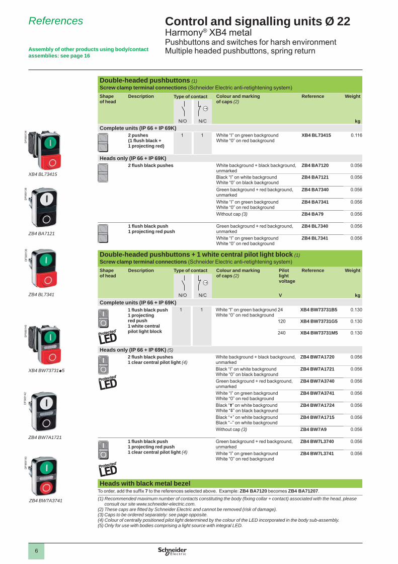
Double-headed pushbuttons (1)Screw clamp terminal connections (Schneider Electric anti-retightening system)Shape of head
Description Type of contact Colour and marking of caps (2)
Reference Weight
N/O N/C kg
Complete units (IP 66 + IP 69K) 2 pushes
(1 fl ush black + 1 projecting red)
1 1 White “I” on green backgroundWhite “0” on red background
XB4 BL73415 0.116
Heads only (IP 66 + IP 69K) 2 fl ush black pushes White background + black background,
unmarkedZB4 BA7120 0.056
Black “I” on white backgroundWhite “0” on black background
ZB4 BA7121 0.056
Green background + red background, unmarked
ZB4 BA7340 0.056
White “I” on green backgroundWhite “0” on red background
ZB4 BA7341 0.056
Without cap (3) ZB4 BA79 0.056
1 fl ush black push 1 projecting red push
Green background + red background, unmarked
ZB4 BL7340 0.056
White “I” on green backgroundWhite “0” on red background
ZB4 BL7341 0.056
Double-headed pushbuttons + 1 white central pilot light block (1)Screw clamp terminal connections (Schneider Electric anti-retightening system)Shape of head
Description Type of contact Colour and markingof caps (2)
Pilot lightvoltage
Reference Weight
N/O N/C V kg
Complete units (IP 66 + IP 69K)1 fl ush black push1 projecting red push1 white central pilot light block
1 1 White “I” on green backgroundWhite “0” on red background
24 XB4 BW73731B5 0.130
120 XB4 BW73731G5 0.130
240 XB4 BW73731M5 0.130
Heads only (IP 66 + IP 69K) (5) 2 fl ush black pushes
1 clear central pilot light (4)White background + black background, unmarked
ZB4 BW7A1720 0.056
Black “I” on white backgroundWhite “0” on black background
ZB4 BW7A1721 0.056
Green background + red background, unmarked
ZB4 BW7A3740 0.056
White “I” on green backgroundWhite “0” on red background
ZB4 BW7A3741 0.056
Black “A” on white backgroundWhite “R” on black background
ZB4 BW7A1724 0.056
Black “+” on white backgroundBlack “–” on white background
ZB4 BW7A1715 0.056
Without cap (3) ZB4 BW7A9 0.056
1 fl ush black push1 projecting red push1 clear central pilot light (4)
Green background + red background, unmarked
ZB4 BW7L3740 0.056
White “I” on green backgroundWhite “0” on red background
ZB4 BW7L3741 0.056
Heads with black metal bezelTo order, add the suffi x 7 to the references selected above. Example: ZB4 BA7120 becomes ZB4 BA71207.(1) Recommended maximum number of contacts constituting the body (fi xing collar + contact) associated with the head, please
consult our site www.schneider-electric.com. (2) These caps are fi tted by Schneider Electric and cannot be removed (risk of damage).(3) Caps to be ordered separately: see page opposite. (4) Colour of centrally positioned pilot light determined by the colour of the LED incorporated in the body sub-assembly.(5) Only for use with bodies comprising a light source with integral LED.
Assembly of other products using body/contact assemblies: see page 16
ZB4 BW7A3741
DF5
6915
0
ZB4 BW7A1721
DF5
6914
2
XB4 BW73731p5
DF5
6914
0
ZB4 BL7341
DF5
6913
8
ZB4 BA7121
DF5
6913
6
XB4 BL73415
DF5
6913
4

7
Control and signalling units Ø 22Harmony® XB4 metalPushbuttons and switches for harsh environmentMultiple headed pushbuttons, spring return
References
Triple-headed pushbuttons (1) (2)Screw clamp terminal connections (Schneider Electric anti-retightening system)Shape of head
Description Type of contact Colour and marking of caps (3)
Reference Weight
N/O N/C N/O kg
Complete units (IP 66 + IP 69K)
2 fl ush black pushes+ 1 central projecting red push marked “Stop” in white
1 1 1 White “I” on green backgroundWhite “II” on green background
XB4 BA731327 0.128
Black “V” on white backgroundWhite “B” on black background
XB4 BA711237 0.128
Heads only (IP 66 + IP 69K)2 fl ush black pushes+ 1 central projecting red push marked “Stop” in white
White “I” on green backgroundWhite “II” on green background
ZB4 BA73132 0.056
White “B” on green backgroundWhite “C” on green background
ZB4 BA73133 0.056
White “Z” on green backgroundWhite “R” on green background
ZB4 BA73134 0.056
White “+” on green backgroundWhite “–” on green background
ZB4 BA73135 0.056
Black “+” on white backgroundBlack “–” on white background
ZB4 BA71115 0.056
Black “V” on white backgroundWhite “B” on black background
ZB4 BA71123 0.056
Black “A” on white backgroundWhite “R” on black background
ZB4 BA71124 0.056
White “Z” on black backgroundWhite “R” on black background
ZB4 BA72124 0.056
Without cap (4) ZB4 BA791 0.056
Specifi c accessories for multiple-headed pushbuttonsDescription Background colour Marking Sold in
lots ofReference Weight
kgCaps only for clip-on mounting (5) on: - ZB4 BA79 double-headed pushbuttons- ZB4 BW7A9 double-headed pushbuttons + central pilot light block- ZB4 BA791 triple-headed pushbuttons
White Unmarked 10 ZBA 71 0.010“I” black 10 ZBA 7131 0.010“V” black 10 ZBA 7134 0.010“+” black 10 ZBA 7138 0.010
Black Unmarked 10 ZBA 72 0.010"O" white 10 ZBA 7232 0.010“+” white 10 ZBA 7233 0.010“C” white 10 ZBA 7235 0.010“I” white 10 ZBA 7237 0.010
Green Unmarked 10 ZBA 73 0.010“I” white 10 ZBA 7331 0.010“+” white 10 ZBA 7333 0.010“Z” white 10 ZBA 7335 0.010“II” white 10 ZBA 7336 0.010
Red Unmarked 10 ZBA 74 0.010"O" white 10 ZBA 7432 0.010
Yellow Unmarked 10 ZBA 75 0.010Blue Unmarked 10 ZBA 76 0.010
Clear silicone boots (6) For 2 fl ush pushes – 10 ZBA 708 0.055For 3 pushes – 10 ZBA 709 0.055For 1 fl ush push + 1 projecting push
– 10 ZBA 710 0.055
Heads with black metal bezelTo order, add the suffi x 7 to the references selected above.Example: ZB4 BA73132 becomes ZB4 BA731327.(1) Recommended maximum number of contacts constituting the body (fi xing collar + contact) associated with the head, please
consult our site www.schneider-electric.com.(2) Not compatible with high power switching contacts and contacts for printed circuit board.(3) These caps are fi tted by Schneider Electric and cannot be removed (risk of damage).(4) Caps to be ordered separately: see accessories on this page.(5) Can be clipped-in at 90° steps, through 360°.(6) Can be replaced without dismantling the head.
DF5
4058
5
ZBA 7235
DF5
4058
5
ZBA 7235
DF5
6917
7
ZBA 7331
DF5
6917
7
ZBA 7331
DF5
6917
8
ZBA 7432
DF5
6917
8
ZBA 7432
XB4 BA731327
DF5
6914
4
ZB4 BA73133
DF5
6914
6
ZB4 BA71124
DF5
6914
8
ZBA 709
DF5
4059
8
Assembly of other products using body/contact assemblies: see page 16

8
Control and signalling units Ø 22Harmony® XB4 metalPushbuttons and switches for harsh environmentEmergency stop devices conforming to EN/IEC 60204-1, to EN/ISO 13850 and Machinery Directive 2006/42/EC
References
Mushroom head Emergency stop trigger action and mechanical latching pushbuttons conform to standards EN/IEC 60204-1 and EN/ISO 13850, to Machinery Directive 2006/42/EC and to standard EN/IEC 60947-5-5. Please consult your Customer Care Centre for a full explanation of these standards and directives.
Emergency stop trigger action and mechanical latching pushbuttons (1) Screw clamp terminal connections (Schneider Electric anti-retightening system)Complete units (IP 66)Shape of head
Type of reset
Type of contact Push Reference Weight
kg
Ø (mm) Colour
N/O N/C
Push-pull 1 1 40 Red XB4 BT845(ZB4 BZ105 + ZB4 BT84)
0.136
Turn to release 1 1 40 Red XB4 BS8445(ZB4 BZ105 + ZB4 BS844)
0.130
– 2 40 Red XB4 BS8444(ZB4 BZ104 + ZB4 BS844)
0.130
1 2 40 Red XB4 BS84441(ZB4 BZ141 + ZB4 BS844)
0.140
Key release (key n° 455)
(2)
1 1 40 Red XB4 BS9445(ZB4 BZ105 + ZB4 BS944)
0.170
Heads only (IP 66)Shape of head
Type of reset
Push Reference WeightØ mm Colour kg
Push-pull 30 Red ZB4 BT844 0.078
40 Red ZB4 BT84 0.078
60 Red ZB4 BX84 0.098
Turn to release 30 Red ZB4 BS834 0.068
40 Red ZB4 BS844 0.073
60 Red ZB4 BS864 0.093
Key release (key n° 455)2 keys included with head (3)
(2)
30 Red ZB4 BS934 0.094
40 Red ZB4 BS944 0.098
60 Red ZB4 BS964 0.118
Bellows for harsh environment (IP 69K) (4)For use in Material Colour Sold in
lots ofUnit reference
Weightkg
Environment subject tohumidity, dust, high pressurecleaning, etc.
Silicone Red 2 ZBZ 48 0.009
EPDM Black 2 ZBZ 28 0.009
Yellow 2 ZBZ 58 0.009
Heads with black metal bezelTo order, add a fi gure 7 to the references selected above. Example: ZB4 BT844 becomes ZB4 BT8447.
(1) It is recommended that a legend or yellow background is used.(2) The symbol indicates key withdrawal position(s).(3) For specifi c keys with other numbers, please consult your Customer Care Centre.(4) Not compatible with Ø 30 Emergency Stop head.
DF5
2400
8
ZBZ p8
Assembly of other products using body/contact assemblies: see page 16
XB4 BT845
1071
7110
7172
XB4 BS9445
1071
76
XB4 BS834

9
Control and signalling units Ø 22Harmony® XB4 metalPushbuttons and switches for harsh environmentSelector switches and key switches
References
Selector switches with standard handle and key switches Screw clamp terminal connections (Schneider Electric anti-retightening system)Shape of head
Type of operator
Positions Reference WeightkgNumber Type
Heads only (IP 66 + IP 69K) Selector switch
with standard handle, black
2-position90°
Stay put ZB4 BD2 0.040
Spring returnfrom right to left
ZB4 BD4 0.045
3-position± 45°
Stay put ZB4 BD3 0.040
Spring returnto centre
ZB4 BD5 0.040
Spring returnfrom left to centre
ZB4 BD7 0.040
Spring returnfrom right to centre
ZB4 BD8 0.040
Key switch withkey n° 455 (1) (2)
2-position90°
Stay put ZB4 BG2 0.098
ZB4 BG02 0.098
ZB4 BG4 0.098
Spring return from right to left
ZB4 BG6 0.098
3-position± 45°
Stay put ZB4 BG0 0.098
ZB4 BG03 0.098
ZB4 BG04 0.098
ZB4 BG3 0.098
ZB4 BG5 0.098
ZB4 BG9 0.098
ZB4 BG09 0.098
Heads with black metal bezelFor heads with standard black handle only. To order, add the suffi x 7 to the references selected from above.Example: ZB4 BD2 becomes ZB4 BD27.
Replacement keys Description Key number Reference Weight
kgKeys for booted selector switches
Sets of 2 keys, one of which supplied booted(rubber boot)
455 ZBG 455P –421E ZBG 421EP –458A ZBG 458AP –520E ZBG 520EP –3131A ZBG 3131AP –
Accessory for key switches (3)Description Function Reference Weight
kgKeyhole cover(rubber cover)
Protection of lock barrel when no key inserted in lock ZBG P 0.005
Boot for standard handleDescription For use with Sold in
lots ofUnit reference
Weight kg
Boot for standard handle
ZB4 BDp 5 ZBD D2 0.005
(1) The symbol indicates key withdrawal position(s).(2) For specifi c keys with other numbers, please consult your Customer Care Centre. (3) Not compatible with products with key TEC10.
Assembly of other products using body/contact assemblies: see page 16
1065
54
ZBG 455P
PF1
0023
2
ZBD D2
ZBG P
PF1
0023
3
ZB4 BD4
PF1
0619
5P
F106
199
ZB4 BG0

10
Control and signalling units Ø 22Harmony® XB5 plasticPushbuttons and switches for harsh environmentSpring return pushbuttons, unmarked or with marking
References
Assembly of other products using body/contact assemblies: see page 16
Pushbuttons with integrated bellowShape of head Colour of push Reference Weight
kg
Heads only, Ø 37 mm (IP 66 + IP 69K) without markingFlush White ZB5 AC180 0.024
Black ZB5 AC280 0.024
Green ZB5 AC380 0.024
Red ZB5 AC480 0.024
Yellow ZB5 AC580 0.024
Blue ZB5 AC680 0.024
Grey ZB5 AC780 0.024
Light blue ZB5 AC980 0.024
Heads only, Ø 37 mm (IP 66 + IP 69K) with markingOther versions Customization with marking at your choice (texts or symbols)
Rotation of head for horizontal mounting of the contact block (1)Please consult our Customer Care Centre.
AccessoriesDescription Function Reference Weight
kgProtective guard in plastic Protection against accidental
operationZBZ 1902 (2) 0.010
Boot for contact blockZBE 10p, ZBE 10p3 andZBE 50p (3)
Protection against liquid anddust ingress
ZBZ 60 r 0.098
(1) Heads are fi xed relative to the position of the contact blocks: contact blocks are normally used in the “vertical” position. It is necessary to order an alternative head with the symbol rotated by 90° in order to mount the contact block in the “horizontal” position (see images page 2). Please add the suffi x «RA» in the end of the references for alternative heads of your choice.(2) For heads with the RA suffi x (ZB5 ACppppRA) used with a guard, it is necessary to order the dedicated guard ZBZ 1902RA.(3) Restriction for use: refer to the product instruction sheet on www.schneider-electric.com.
r Available: 3rd quarter 2011.
ZB5 AC680
PF1
0121
2
ZBZ 60
PF1
0121
4
ZBZ 1902
PF1
0120
3

11
Pushbuttons with silicone booted headScrew clamp terminal connections (Schneider Electric anti-retightening system)Shape of head
Type of push
Type of contact Colour of push
Reference Weight
kg
N/O N/C
Complete units (IP 66 + IP 69K) Booted,
clear silicone(colour of push unobscured)
1 – Black XB5 AP21(ZB5 AZ101 + ZB5 AP2)
0.039
Green XB5 AP31(ZB5 AZ101 + ZB5 AP3)
0.039
Yellow XB5 AP51 (ZB5 AZ101 + ZB5 AP5)
0.039
Blue XB5 AP61(ZB5 AZ101 + ZB5 AP6)
0.039
– 1 Red XB5 AP42(ZB5 AZ102 + ZB5 AP4)
0.039
Silicone booted heads only, with increased protection (IP 66 + IP 69K)Flush Clear boot (1)
For insertion of protected legend within head (2)White ZB5 AP18 0.023Green ZB5 AP38 0.023Red ZB5 AP48 0.023Yellow ZB5 AP58 0.023Blue ZB5 AP68 0.023
Projecting Clear boot (1) White ZB5 AP1 0.014Black ZB5 AP2 0.014Green ZB5 AP3 0.014Red ZB5 AP4 0.014Yellow ZB5 AP5 0.014Blue ZB5 AP6 0.014
Silicone booted heads only, standard for mounting with legend holder (IP 66)Flush Coloured boot White ZB5 AP1S 0.021
Black ZB5 AP2S 0.021Green ZB5 AP3S 0.021Red ZB5 AP4S 0.021Yellow ZB5 AP5S 0.021Blue ZB5 AP6S 0.021
Clear membraneFor insertion of protected legend within head (2)
White ZB5 AP183 0.010Green ZB5 AP383 0.010Red ZB5 AP483 0.010Yellow ZB5 AP583 0.010Blue ZB5 AP683 0.010
Transparent boots for pushbuttonsDescription For use with pushbutton types Sold in
lots ofUnit reference
Weight kg
Single boots (1) Flush with circular head 10 ZBP A 0.002Projecting with circular head and push-push version
10 ZBP 0 0.002
Flush or projecting with circular headfor food industry applications
10 ZBP 0A 0.002
Coloured bootsDescription Colour For use with Sold in
lots ofUnit reference
Weight kg
Coloured boots (3)
Black ZB5 AP2S 10 ZBP 012 0.003Green ZB5 AP3S 10 ZBP 013 0.003Red ZB5 AP4S 10 ZBP 014 0.003Yellow ZB5 AP5S 10 ZBP 015 0.003Blue ZB5 AP6S 10 ZBP 016 0.003
Heads with black metal bezelTo order, add a fi gure 7 to the references selected from above. Example: ZB5 AP18 becomes ZB5 AP187.(1) Permissible panel thickness 1 to 5 mm, cannot be used with legend holders.(2) To order a legend for insertion within the head, please consult our site www.schneider-electric.com.(3) Can be replaced without dismantling the head.
Control and signalling units Ø 22Harmony® XB5 plasticPushbuttons and switches for harsh environmentSpring return pushbuttons, unmarked
References
Assembly of other products using body/contact assemblies: see page 16
1094
99
ZB5 AP183
ZBP 0
1073
6010
1287
XB5 AP51
ZB5 AP4
1102
67
ZB5 AP6S
PG
1138
76

12
Double-headed pushbuttons (1)Screw clamp terminal connections (Schneider Electric anti-retightening system)Shape of head
Description Type of contact Colour and marking of caps (2)
Reference Weight
N/O N/C kg
Complete units (IP 66 + IP 69K) 2 pushes
(1 fl ush black + 1 projecting red)
1 1 White “I” on green backgroundWhite “0” on red background
XB5 AL73415 0.053
Heads only (IP 66 + IP 69K) 2 fl ush black pushes White background + black background,
unmarkedZB5 AA7120 0.023
Black “I” on white backgroundWhite “0” on black background
ZB5 AA7121 0.023
Green background + red background, unmarked
ZB5 AA7340 0.023
White “I” on green backgroundWhite “0” on red background
ZB5 AA7341 0.023
Without cap (3) ZB5 AA79 0.023
1 fl ush black push 1 projecting red push
Green background + red background, unmarked
ZB5 AL7340 0.023
White “I” on green backgroundWhite “0” on red background
ZB5 AL7341 0.023
Double-headed pushbuttons + 1 white central pilot light block (1) Screw clamp terminal connections (Schneider Electric anti-retightening system)Shape of head
Description Type of contact Colour and markingof caps (2)
Pilot lightvoltage
Reference Weight
N/O N/C V kg
Complete units (IP 66 + IP 69K)1 fl ush black push1 projecting red push1 white central pilot light block
1 1 White “I” on green backgroundWhite “0” on red background
24 XB5 AW73731B5 0.066
120 XB5 AW73731G5 0.066
240 XB5 AW73731M5 0.066
Heads only (IP 66 + IP 69K) (5) 2 fl ush black pushes
1 clear central pilot light (4)White background + black background, unmarked
ZB5 AW7A1720 0.023
Black “I” on white backgroundWhite “0” on black background
ZB5 AW7A1721 0.023
Green background + red background, unmarked
ZB5 AW7A3740 0.023
White “I” on green backgroundWhite “0” on red background
ZB5 AW7A3741 0.023
Black “A” on white backgroundWhite “R” on black background
ZB5 AW7A1724 0.023
Black “+” on white backgroundBlack “–” on white background
ZB5 AW7A1715 0.023
Without cap (3) ZB5 AW7A9 0.023
1 fl ush black push1 projecting red push1 clear central pilot light (4)
Green background + red background, unmarked
ZB5 AW7L3740 0.023
White “I” on green backgroundWhite “0” on red background
ZB5 AW7L3741 0.023
(1) Recommended maximum number of contacts constituting the body (fi xing collar + contact) associated with the head, please consult our site www.schneider-electric.com. (2) These caps are fi tted by Schneider Electric and cannot be removed (risk of damage).(3) Caps to be ordered separately: see page opposite. (4) Colour of centrally positioned pilot light determined by the colour of the LED incorporated in the body sub-assembly.(5) Only for use with bodies comprising a light source with integral LED.
ZB5 AW7A3741
DF5
6914
9
ZB5 AW7A1721
DF5
6914
1
XB5 AW73731p5
DF5
6913
9
ZB5 AL7341
DF5
6913
7
ZB5 AA7121
DF5
6913
5
XB5 AL73415
DF5
6913
3Control and signalling units Ø 22Harmony® XB5 plasticPushbuttons and switches for harsh environmentMultiple-headed pushbuttons, spring return
References
Assembly of other products using body/contact assemblies: see page 16
13
Control and signalling units Ø 22Harmony® XB5 plasticPushbuttons and switches for harsh environmentMultiple-headed pushbuttons, spring returnAssembly of other products using body/contact
assemblies: see page 16
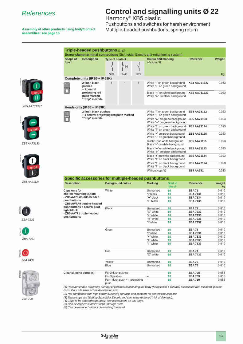
Triple-headed pushbuttons (1) (2)Screw clamp terminal connections (Schneider Electric anti-retightening system)Shape of head
Description Type of contact Colour and marking of caps (3)
Reference Weight
N/O N/C N/O kg
Complete units (IP 66 + IP 69K)
2 fl ush black pushes+ 1 central projecting red push marked “Stop” in white
1 1 1 White “I” on green backgroundWhite “II” on green background
XB5 AA731327 0.063
Black “V” on white backgroundWhite “B” on black background
XB5 AA711237 0.063
Heads only (IP 66 + IP 69K)2 fl ush black pushes+ 1 central projecting red push marked “Stop” in white
White “I” on green backgroundWhite “II” on green background
ZB5 AA73132 0.023
White “B” on green backgroundWhite “C” on green background
ZB5 AA73133 0.023
White “Z” on green backgroundWhite “R” on green background
ZB5 AA73134 0.023
White “+” on green backgroundWhite “–” on green background
ZB5 AA73135 0.023
Black “+” on white backgroundBlack “–” on white background
ZB5 AA71115 0.023
Black “V” on white backgroundWhite “B” on black background
ZB5 AA71123 0.023
Black “A” on white backgroundWhite “R” on black background
ZB5 AA71124 0.023
White “Z” on black backgroundWhite “R” on black background
ZB5 AA72124 0.023
Without cap (4) ZB5 AA791 0.023
Specifi c accessories for multiple-headed pushbuttonsDescription Background colour Marking Sold in
lots ofReference Weight
kgCaps only for clip-on mounting (5) on: - ZB5 AA79 double-headed pushbuttons- ZB5 AW7A9 double-headed pushbuttons + central pilot light block- ZB5 AA791 triple-headed pushbuttons
White Unmarked 10 ZBA 71 0.010“I” black 10 ZBA 7131 0.010“V” black 10 ZBA 7134 0.010“+” black 10 ZBA 7138 0.010
Black Unmarked 10 ZBA 72 0.010"O" white 10 ZBA 7232 0.010“+” white 10 ZBA 7233 0.010“C” white 10 ZBA 7235 0.010“I” white 10 ZBA 7237 0.010
Green Unmarked 10 ZBA 73 0.010“I” white 10 ZBA 7331 0.010“+” white 10 ZBA 7333 0.010“Z” white 10 ZBA 7335 0.010“II” white 10 ZBA 7336 0.010
Red Unmarked 10 ZBA 74 0.010"O" white 10 ZBA 7432 0.010
Yellow Unmarked 10 ZBA 75 0.010Blue Unmarked 10 ZBA 76 0.010
Clear silicone boots (6) For 2 fl ush pushes – 10 ZBA 708 0.055For 3 pushes – 10 ZBA 709 0.055For 1 fl ush push + 1 projecting push
– 10 ZBA 710 0.055
(1) Recommended maximum number of contacts constituting the body (fi xing collar + contact) associated with the head, please consult our site www.schneider-electric.com.(2) Not compatible with high power switching contacts and contacts for printed circuit board.(3) These caps are fi tted by Schneider Electric and cannot be removed (risk of damage).(4) Caps to be ordered separately: see accessories on this page.(5) Can be clipped-in at 90° steps, through 360°.(6) Can be replaced without dismantling the head.
DF5
4058
5
ZBA 7235
DF5
4058
5
ZBA 7235
DF5
6917
7
ZBA 7331
DF5
6917
7
ZBA 7331
DF5
6917
8
ZBA 7432
DF5
6917
8
ZBA 7432
XB5 AA731327
DF5
6914
3
ZB5 AA73133
DF5
6914
5
ZB5 AA71124
DF5
6914
7
ZBA 709
DF5
4059
8
References

14
Mushroom head Emergency stop trigger action and mechanical latching pushbuttons conform to standards EN/IEC 60204-1 and EN/ISO 13850, to Machinery Directive 2006/42/EC and to standard EN/IEC 60947-5-5. Please consult your Customer Care Centre for a full explanation of these standards and directives.
Emergency stop trigger action and mechanical latching pushbuttons (1)Screw clamp terminal connections (Schneider Electric anti-retightening system)Shape of head
Type of reset
Type of contact Push Reference Weight
Ø (mm) Colour
N/O N/C kgComplete units (IP 66)
Push-pull 1 1 40 Red XB5 AT845(ZB5 AZ105 + ZB5 AT84)
0.076
Turn to release
1 1 40 Red XB5 AS8445(ZB5 AZ105 + ZB5 AS844)
0.072
– 2 40 Red XB5 AS8444(ZB5 AZ104 + ZB5 AS844)
0.072
Key release (key n° 455)
(2)
1 1 40 Red XB5 AS9445 (ZB5 AZ105 + ZB5 AS944)
0.112
Heads only (IP 66)Shape of head
Type of reset
Push Reference WeightkgØ (mm) Colour
Push-pull 30 Red ZB5 AT844 0.050
40 Red ZB5 AT84 0.050
60 Red ZB5 AX84 0.050
Turn to release 30 Red ZB5 AS834 0.042
40 Red ZB5 AS844 0.046
Key release (key n° 455) (3)2 keys included with head
(2)
30 Red ZB5 AS934 0.068
40 Red ZB5 AS944 0.071
60 Red ZB5 AS964 0.092
Key release (key n° 4A185) (3) 40 Red ZB5 AS944D 0.071
Bellows for harsh environment (IP 69K) (4)For use in Material Colour Sold in
lots ofUnit reference
Weightkg
Environment subject tohumidity, dust, high pressurecleaning, etc.
Silicone Red 2 ZBZ 48 0.009EPDM Black 2 ZBZ 28 0.009
Yellow 2 ZBZ 58 0.009
(1) It is recommended that a legend or yellow background is used.(2) The symbol indicates key withdrawal position(s).(3) For specifi c keys with other numbers, please consult your Customer Care Centre.(4) Not compatible with Ø 30 Emergency Stop head.
Control and signalling units Ø 22Harmony® XB5 plasticPushbuttons and switches for harsh environmentEmergency stop devices conforming to EN/IEC 60204-1, to EN/ISO 13850 and Machinery Directive 2006/42/EC
ReferencesD
F524
008
ZBZ p8
Assembly of other products using body/contact assemblies: see page 16
PF1
0718
3
XB5 AT845
ZB5 AS844
1071
88
XB5 AS9445
1071
82
XB5 AS8445
1071
84

15
Control and signalling units Ø 22Harmony® XB5 plasticPushbuttons and switches for harsh environmentSelector switches and key switches
References
Selector switches with standard handle and key switches Screw clamp terminal connections (Schneider Electric anti-retightening system)Shape of head
Type of operator
Positions Reference WeightkgNumber Type
Heads only (IP 66 + IP 69K) Standard
handle, black
2-position90°
Stay put ZB5 AD2 0.017
Spring returnfrom right to left
ZB5 AD4 0.020
3-position± 45°
Stay put ZB5 AD3 0.017
Spring returnto centre
ZB5 AD5 0.017
Spring returnfrom left to centre
ZB5 AD7 0.017
Spring returnfrom right to centre
ZB5 AD8 0.017
Key switchwith key n° 455(1) (2)
2-position90°
Stay put ZB5 AG2 0.057
ZB5 AG02 0.057
ZB5 AG4 0.057
Spring return from right to left
ZB5 AG6 0.061
3-position± 45°
Stay put ZB5 AG0 0.057
ZB5 AG3 0.057
ZB5 AG5 0.057
ZB5 AG9 0.057
ZB5 AG09 0.057
Spring returnfrom left to centre
ZB5 AG1 0.057
Spring returnto centre
ZB5 AG7 0.057
Spring return from right to center
ZB5 AG8 0.057
ZB5 AG05 0.057
Heads with black metal bezelFor heads with standard black handle only. To order, add the suffi x 7 to the references selected from above.Example: ZB5 AD2 becomes ZB5 AD27.
Replacement keys Description Key number Reference Weight
kgKeys for booted selector switches
Sets of 2 keys, one of which supplied booted(rubber boot)
455 ZBG 455P –421E ZBG 421EP –458A ZBG 458AP –520E ZBG 520EP –3131A ZBG 3131AP –
Accessory for key switches (3)Description Function Reference Weight
kgKeyhole cover(rubber cover)
Protection of lock barrel when no key inserted in lock
ZBG P 0.005
Boot for standard handleDescription For use with Sold in
lots ofUnit reference
Weight kg
Boot for standard handle
ZB5 ADp 5 ZBD D2 0.005
(1) The symbol indicates key withdrawal position(s).(2) For specifi c keys with other numbers, please consult your Customer Care Centre. (3) Not compatible with products with key TEC10.
Assembly of other products using body/contact assemblies: see page 16
1065
54
ZBG 455P
PF1
0023
2
ZBD D2
ZBG P
PF1
0023
3P
F106
215
ZB5 AD2
PF1
0622
3
ZB5 AG3

16
Control and signalling units Ø 22Harmony® XB4 metal and XB5 plasticPushbuttons and switches for harsh environmentBody/contact assemblies
References
Contact functions - Screw clamp terminal connections (Schneider Electric anti-retightening system)Contacts for standard applicationsDescription Type of contact
Sold in lots of
Unit reference
Weight
kgN/O N/C
Contacts blocks(for Harmony XB4 metal range)
Single with body/fi xing collar 1 – 1 ZB4 BZ101 0.053
– 1 1 ZB4 BZ102 0.053
2 – 1 ZB4 BZ103 0.062
– 2 1 ZB4 BZ104 0.062
1 1 1 ZB4 BZ105 0.062
1 2 1 ZB4 BZ141 0.072
Contacts blocks(for Harmony XB5 metal range)
Single with body/fi xing collar 1 – 1 ZB5 AZ101 0.021
– 1 1 ZB5 AZ102 0.021
2 – 1 ZB5 AZ103 0.030
– 2 1 ZB5 AZ104 0.030
1 1 1 ZB5 AZ105 0.030
1 2 1 ZB5 AZ141 0.040
Contact functions - Spring clamp terminal connectionsContacts for standard applicationsDescription Type of contact
Sold in lots of
Unit reference
Weight
kgN/O N/C
Contacts blocks(for Harmony XB4 metal range)
Single with body/fi xing collar 1 – 1 ZB4 BZ1015 0.053
– 1 1 ZB4 BZ1025 0.053
2 – 1 ZB4 BZ1035 0.062
– 2 1 ZB4 BZ1045 0.062
1 1 1 ZB4 BZ1055 0.062
Contacts blocks(for Harmony XB5 metal range)
Single with body/fi xing collar 1 – 1 ZB5 AZ1015 0.021
– 1 1 ZB5 AZ1025 0.021
2 – 1 ZB5 AZ1035 0.030
– 2 1 ZB5 AZ1045 0.030
1 1 1 ZB5 AZ1055
0.030
To combine with XB4 metal heads, see page 4To combine with XB5 plastic heads, see page 10
ZB5 AZ101
1013
63P
F107
779
ZB4 BZ1015
ZB5 AZ1015
PF1
0778
110
1274
ZB4 BZ101

17
Body/fi xing collarContacts for standard applicationsFor use with Type of range Sold in lots of Unit
referenceWeight
kgElectrical block(contact or light)
Harmony XB4 metal 10 ZB4 BZ009 0.038
Harmony XB5 plastic 10 ZB5 AZ009 0.038
Contact functions - Screw clamp terminal connections (Schneider Electric anti-retightening system)Contacts for standard applicationsDescription Type of contact
Sold in lots of
Unit reference
Weight
kgN/O N/CContact blocks(for Harmony XB4 metal and XB5 plastic ranges)
Single 1 – 5 ZBE 101 0.011
– 1 5 ZBE 102 0.011
Double 2 – 5 ZBE 203 0.020
– 2 5 ZBE 204 0.020
1 1 5 ZBE 205 0.020
Contacts for specifi c applicationsApplication Type of
contactDescription
Sold in lots of
Unit reference
Weight
kgN/O N/CContact blocks for lowpower switching(for Harmony XB4 metal and XB5 plastic ranges)
Single Standard 1 – 5 ZBE 1016 0.012
– 1 5 ZBE 1026 0.012
Dusty environment (1)(IP5X, 50 μm dust)
1 – 5 ZBE 1016P 0.012
– 1 5 ZBE 1026P 0.012
Contact blocks for highpower switching(for Harmony XB4 metal and XB5 plastic ranges)
Single Standard (2) 1 – 1 ZBE 501 0.020
– 1 1 ZBE 502 0.020
2 – 1 ZBE 503 0.032
– 2 1 ZBE 504 0.032
1 1 1 ZBE 505 0.032
Contact functions - Spring clamp terminal connectionsContacts for standard applicationsDescription Type of contact
Sold in lots of
Unit reference
Weight
kgN/O N/C
Contact blocks(for Harmony XB4 metal and XB5 plastic ranges)
Single 1 – 4 ZBE 1015 0.011
– 1 4 ZBE 1025 0.011
(1) It is not possible to fi t an additional contact block on the back of these contact blocks.(2) It is not possible to add further contacts to these assemblies.
Control and signalling units Ø 22Harmony® XB4 metal and XB5 plasticPushbuttons and switches for harsh environmentBody/contact assemblies
References
To combine with XB4 metal heads, see page 4To combine with XB5 plastic heads, see page 10
ZBE 1015
PF1
0777
7
ZBE 501
PF0
8070
6
ZBE 203
1012
6710
1191
ZB4 BZ009
ZBE 101
1012
6410
1368
ZB5 AZ009

The information provided in this documentation contains general descriptions and/or technical characteristics of the performance of the products contained herein. This documentation is not intended as a substitute for and is not to be used for determining suitability or reliability of these products for specifi c user applications. It is the duty of any such user or integrator to perform the appropriate and complete risk analysis, evaluation and testing of the products with respect to the relevant specifi c application or use thereof. Neither Schneider Electric nor any of its affi liates or subsidiaries shall be responsible or liable for misuse of the information contained herein.
Design: Schneider ElectricPhotos: Schneider ElectricPrinted by:
Head Offi ce35, rue Joseph MonierF-92500 Rueil-MalmaisonFrance
www.schneider-electric.comSchneider Electric Industries SAS
ART. 960605 June 2011
DIA
5ED
2110
706E
N
Schn
eide
r Ele
ctri
cH
arm
ony
XB
4/X
B5
co
ntro
l and
sig
nalli
ng u
nits
fo
r ha
rsh
envi
ronm
ents
11

![Zelio Logic and Altivar - eschneider.pl Automatyka przemyslowa/Aplikacje... · and Altivar on CANopen System User Guide [source code] 33003500.01 . ... alternative to manual operation](https://static.fdocuments.us/doc/165x107/5abeae277f8b9a5d718d47a5/zelio-logic-and-altivar-automatyka-przemyslowaaplikacjeand-altivar-on-canopen.jpg)