
Catalogue - I N T E L E C T · Phone. +7 (495) 615-0523, 615-7302 [email protected] TABLE OF CONTENTS...
56
Moscow Radio Monitoring Equipment Catalogue
Transcript of Catalogue - I N T E L E C T · Phone. +7 (495) 615-0523, 615-7302 [email protected] TABLE OF CONTENTS...

Moscow
Radio MonitoringEquipment
Catalogue

Phone: +7(495) 615-0523, 615-7302E-mail: [email protected]
Internet www.ircos.ru
Since 1992 we produce equi pment for automated radiomonitoring, direct ion f inding, measurement of radio s ignal parameters and compromising emanation survey.
IRCOS JSCInvestigation on Radiomonitoring and System Design
IRCOS JSC Today:
Post address: 129626, P.O. Box 30, Moscow, RussiaOfice: 19, Zviezdny bul., Moscow, Russia
Fax: +7(495) 615-7302
Well-knit team of high-skilled specialists ●System engineering approach ●Modern concepts of the equipment design ●Complete cycle all basic system component production ●Production facilities: 3000 m ● 2
Quality management ●
Reliable high technology products ●Wide range of radiomonitoring and direction ●finding equipmentState licenses for all basic company activities ●RF patents on technical solution ●
Certif ied measuring equipment ●Honorary award and diploma ●Training center ●

Phone. +7 (495) 615-0523, 615-7302
www.ircos.ru [email protected]
TABLE OF CONTENTS 3
FOREWORD 4
ABOUT COMPANY 5
STATIONARY EQUIPMENT 7
ARC-POM1 Multistation Radio Monitoring and Position Finding System 7
ARCHA Stationary Radio Monitoring and Direction Finding Station 7
ARTICUL-S Stationary Direction Finder 9
ARTIKUL-S-8 Stationary Direction Finder 10
ARC-RD6 Panoramic Multi-Channel Receiver 10
MOBILE EQUIPMENT 11
ARC-POM2 Multistation Radio Monitoring and Position Finding System 11
ARGUMENT Mobile Radio Monitoring and Direction Finding Station 11
ARTICUL-M Mobile Direction Finder with Two Antenna Systems 13
ARTICUL-M1 Mobile Direction Finders 15
ARTICUL-M4 Mobile Direction Finder 16
PORTABLE EQUIPMENT 18
ARC-POM3 Portable Multistation Radio Monitoring and Position Finding System 18
ARENA Portable Radio Monitoring and Direction Finding Station 18
ARTICUL-P Portable Automatic Direction Finder 19
ARC-RD6 Panoramic Multi-Channel Receiver 20
ARC-D11 Two-Channel Panoramic Radio Receiver 21
ARC-D1TM-8 Portable Multi-Functional Radio Monitoring System 22
HANDHELD EQUIPMENT 23
ARTIKUL-H1 Manpack Wideband Automatic Direction Finder 23
ARC-RP3, ARC-RP3M Handheld Direction Finders 24
MEASURING EQUIPMENT 26
ARCHA-I Stationary Measuring Radio Monitoring and Direction Finding Station 26
ARGUMENT-I Mobile Measuring Radio Monitoring and Direction Finding Station 27
ARGAMAK-IS Panoramic Field Strength Meter 29
ARGAMAK-IM Panoramic Measuring Receiver 29
ARGAMAK-I Panoramic Measuring Receiver 30
ARC-NK3I Handheld Radio Monitoring and Direction Finding Measuring System 31
ARC-D1TI Multi-Functional Radio Monitoring System 32
ARC-KNV4 Remote Controlled Down-Converter for Measuring Equipment 33
EMERGENCY AND RESCUE EQUIPMENT 34
ARC-CSA Automatic Direction Finder for Emergencies 34
ARC-CSR Manual Direction Finder for Emergencies 34
DIGITAL PANORAMIC RADIO RECEIVERS, TUNERS AND FREQUENCY DOWN-CONVERTERS, TEST GENERATORS 35
ARGAMAK, ARGAMAK-K Panoramic Radio Receiver 35
ARGAMAK-M, ARGAMAK-MK Panoramic Radio Receivers 36
ARGAMAK-T Single-Channel Tuner 36
ARGAMAK-T2 Two-Channel Tuner 37
ARC-PS5 Tuner Module 37
ARC-CPS1 Single Board Tuning and Digital Processing Module 38
ARC-KNV4M Remote-Controlled Frequency Down-Converter 38
ARC-KNV3 Remote-Controlled Frequency Down-Converter 39
ARC-TG3 Test Generator 39
EQUIPMENT FOR RADIO SIGNAL DIGITAL PROCESSING, TECHNICAL ANALYSIS AND RECORDING 40
ARC-CRS2 Signal Digital Recorder 40
ARC-CRS Signal Digital Recorder 40
ARC-ACO-M11 Two-Channel A/D Processing Unit 41
ARC-CO2, ARC-CO5, ARC-CO10 Digital Signal Processing Modules 41
ARC-C5 Two-Channel Special Processing Module 42
ARGAMAK-C Radio Signal Monitoring and Analysis System for HF, VHF, UHF and SHF Communication Systems 42
ANTENNAS AND ANTENNA SYSTEMS 43
ARC-MA2 HF Magnetic Receive Antenna 43
ARC-A7A-3 Broadband Antenna for Installation on Vehicle 43
ARC-A12 Wideband Outdoor Antenna for Installation on Mast 44
AS-PP4 Antenna System 44
AS-PP17 Antenna System 45
AS-PP17-1 Antenna System 45
AS-PP07 Antenna System 45
AS-MP17 Antenna System 46
AS-MP07 Antenna System 46
ARC-MT1 Turnable Dielectric Telescopic Mast 46
ARC-MT3 Telescopic Mast 47
ARC-UP1, ARC-UP2 Remote Controlled Antenna Rotator 47
SOFTWARE 48
SMO-PA Panoramic Analysis Software Package Line 48
SMO-DX Software Package Line for Indoor Measuring and Radio Monitoring 49
SMO-KPA Panoramic Analysis Software Package 50
SMO-STA Technical Analysis Software Package 50
SMO-ASPD Software Package for Spectrum and Bearing Data Analysis 51
SMO-KN Mapping and Navigation Software Package Line 51
SMO-PRANA, SMO-TEST, SMO-RAPIRA Software Sets 52
SMO-BS Software Package Line for Base Station Parameters Analysis 53
NOTES 54
Table of Contents

Phone. +7 (495) 615-0523, 615-7302
www.ircos.ru [email protected]
mainly at measuring electromagnetic field strength and basic radio signal parameters while controlling efficiency of measures on leakage prevention, and also at measuring radio facilities and coverage zones parameters.Update of STATIONARY EQUIPMENT section – based on recent studies, the structure of ARC-POM1 Multistation Radio Monitoring and Position Finding System has been updated. Development of ARTIKUL-S-8 Stationary Direction Finder for 25-8000 MHz is completed and the device is now put into production.PORTABLE EQUIPMET Section – ARC-D1TM has been replaced by ARC-D1TM-8, a more up-to-date device Compared with the previous version, this system provides a higher panoramic analysis rate (1600 MHz/s instead of 600 MHz/c), an extended operating frequency range (8 GHz upper limit instead of 3 GHz) and (on Customer request) IF output at 70 MHz.In 2008 we finished testing of ARTIKUL-H1 and put it into production. This is a unique portable automatic broadband direction finder that does not have any open analogs in the world. The test results are published in PORTABLE EQUIPMENT Section of the catalog. This section also includes a new version of ARC-RP3 Manual Direction Finder – ARC-RP3M (operating frequency range in complete configuration is 25 – 18 000 MHz). This direction finder is smaller, lighter and significantly cheaper than the previous version. ARC-RP3M Direction finder is based on ARGAMAK-M - a new single-board digital receiver.MEASURING EQUIPMENT SECTION now includes a new certified device – ARGAMAK-IS Panoramic Field Strength Meter. It is designed basically for stationary radio monitoring and can be used both as a standalone device and as a part of ARCHA-I measuring station (its description is also included in the catalog). PANORAMIC DIGITAL RADIO RECEIVERS, CONVERTERS AND TEST GENERATORS Section includes description of devices basically designed for signal analog processing. It includes ARGAMAK digital panoramic receivers and modules, ARC-CPS1 and ARC-CPS2 single-board signal conversion and digital processors, signal converters and test generators designed for radio receiving equipment tuning and setting. This section now includes ARGAMAK-M – a single-channel radio receiver with digital and analog components mounted on a single board which makes the receiver smaller, lighter and cheaper than the previous version of ARGAMAK. ARGAMAK-M is used as a part of ARC-RP3M Manual Direction Finder.EQUIPMENT FOR RADIO SIGNAL DIGITAL PROCESSING, TECHNICAL ANALYSIS AND RECORDING Section includes devices designed mainly for analog signal digital processing. It includes a new ARC-CRS2 Digital Signal Recorder, ARC-ACO-M11 Two-Channel Digital Signal Processing Unit, ARC-S5 Two-Channel Special Processing Module and also ARGAMAK-C Radio Signal Monitoring and Analysis System for HF, VHF, UHF and SHF Communication Systems.ANTENNAS and ANTENNA SYSTEMS section includes specifications of broadband antennae for radio monitoring, multi-channel antenna systems, and also dielectric masts meant for antenna or antenna system installation. This section now includes a new broadband HF/VHF magnetic antenna AS-MA2 (9 kHz – 30 MHz) for radio monitoring equipment.Data concerning customized software common for all equipment types is given in CUSTOMIZED SOFTWARE section.
Sincerely yours,IRCOS Director General
Doctor of EngineeringAnatoly Rembovsky
Dear Colleagues!In front of you is the latest annual catalogue of technical means produced by IRCOS which contains data referring product line, basic functions and technical specifications of our products. In 2007 It was f if teen years since we began working in the research and production field we had chosen as our activity. In the intervening years we’ve gone from the first generation equipment based on impor t radio receivers and in-house
analogue-digital processors to the fifth generation equipment based on ARGAMAK series digital panoramic radio receivers and modules. Having its own specific features, functions and technical specifications each unit out of these five generations of radio monitoring equipment has found its customers in power structures, supervisory authorities and security services. Our Company’s technical means are recognized and demanding not only in Russia but far outside. During the existence of the Company:• Five generations of broad product-line of automated radio monitoring
equipment have been developed and mastered• The quality control system has been implemented for fulfilling
Governments’ defense order• Two doctoral and seven candidate dissertations have been defended
by our colleagues• 10 Russian patents have been received for processing methods in
different radio monitoring aspects and devices to implement them• 7 items have been certified as measuring means in GosStandart of
Russia and Federal Agency on Technical Regulation and Metrology• In 2002 – 2008 Company’s equipment was awarded 5 golden
«Quality and security assurance» medals at INTERPОLITEX International Forums and 6 First degree medals at “Safety Technologies” International Forum.
The fifth generation technical means which are included in the catalogue and constructed mostly on the basis of ARGAMAK series modules and blocks are purposed for the following:• Outdoor and indoor automated radio monitoring and radio monitoring
in industrial centers and inside buildings• Radio sources direction finding and position finding• Parameters measuring for radio facilities and energetic coverage
zonesCatalogue 2007 has undergone some changes if compared to the previous one. They have been made not only because new devices are being developed but also because the product line had been changed.In the present catalogue as well as in the previous one all the technical means are divided into stationary, mobile, portable and handheld. Means with permanent position are STATIONARY. MOBILE means are permanently or temporarily placed on ground- or air-based mobile platforms allowing performing their functions while moving. POTABLE means can be carried by a limited number of operators and used at stationary base and temporary stops, also in open terrain. HANDHELD means can be placed on an operator’s body and used while he is moving. Handheld means can be also used for solving radio monitoring tasks at stationary base or temporary stops. Each type of the technical means is describes in the corresponding catalogue section. Besides MEASURING MEANS section is introduced; they are purposed

Phone. +7 (495) 615-0523, 615-7302
www.ircos.ru [email protected]
IRCOS is a modern design and engineering company that specializes in highly integrated systems of automated radio monitoring and direction finding. The company develops, manufactures and tests all basic components of the above systems, including antenna-feeder devices, digital panoramic receivers, HF and VHF sections, digital and analog processing units, power supply systems and special integrated software. The company is also a provider of electromagnetic compatibility solutions for vehicle-based radio equipment. The company products are intended for the following:
Automated radio monitoring, direction finding and locating of radio • emitters in urban/industrial/office/residential environmentParameters measuring for radio facilities and energetic coverage zones• Specialized survey of compromising emanation• Control of data protection effectiveness inside covered areas.•
RESEARCH AND DEVELOPMENT
The company research and engineering activities are based on both theoretical and practical studies of radio monitoring, direction finding, data protection effectiveness control and measuring instruments. We have created a highly effective research and development system that makes us one of the most advanced companies in the industry and provides us with the most up-to-date solutions. Practical approach, close coordination with the manufacturer and feedback from end users enables us to optimally define purposes and scope of our research. Owing to our capacities, we can provide any R&D support for our engineers. Therefore our customers need not pay to any other research organizations and thus can save their time and money.We accumulate professional engineers and researchers. This has been our policy from the very beginning of our business and this is one of the reasons of our success. IRCOS are not just a consumer of research findings. We are also a base for development of the Russian science and engineering. Among our employees there are two doctors of science and seven candidates of science. We have also conducted several scientific studies in our core activities.The company employees hold patents for inventions and technologies. Our company is also a place where a lot of technical university graduates start their careers in the industry.The company participates in International Telecommunications Union (ITU). The company employees included in RF delegation participates in ITU-R workshops for development of additions to Spectrum Radio Control Manual based on company R&D studies. Now there are three contributions developed by the company specialists and accepted:
Localization by a mobile monitoring station of radio signal transmitters in • city conditions taking into account results of field strength measurementsProposed addition to section 3.2.4.1 “VHF and UHF omnidirection types”• Automated site search for sources of electromagnetic emissions.•
The texts of the contributions are available at ITU official site (registration required) or at the company site in Publications.
MANUFACTURING AND NEW APPLICATIONS
IRCOS is a company that implemented a full process cycle and a certified quality control system. For our products we took the best of the process engineering and structure used in the USSR and the RF defense industry. Our company policy is to ensure the maximum possible sustainability and independence from external factors. IRCOS JSC is licensed by the RF Industry Agency and can develop, manufacture and repair defense equipment. Besides our traditional business i.e. manufacturing of equipment for radio monitoring IRCOS is also successful in new fields.In 2002 we started commercial production of radio signal measurement equipment. We have succeeded in that owing to our quality system, research capacities and high level of radio receiver manufacturing achieved in our previous projects. This is a new field not just for our company. In the Russian market there are just a few domestic manufacturers of such equipment and the product range is not large by now. Therefore our progress in this business becomes especially important. In 2008, development of ARGAMAK-IS field strength meter was completed.Currently IRCOS manufacture the following instruments and measuring equipment:
ARK-KNV4 Remote Frequency Down-Converter (GOST-R Certificate of 1. Measuring Equipment Type Approval RU.E.33.018.A No. 17735 as of 04.06.2004. Entered into State Register of Instrumentation Equipment, Reg. No. 26994-04) with built-in directional antenna systemARGAMAK-I Panoramic Measuring Receiver. GOST-R Certificate of 2. Measuring Equipment Type Approval RU.E.35.018.A No. 18189 as of 04.07.2004. Entered into State Register of Measuring Equipment, Reg. No. 27325-04ARC-D1TI Multi-Functional Measuring Radio Monitoring System. GOST-R 3. Certificate of Measuring Equipment Type Approval RU.E.35.018.A No. 18190
About Company

Phone. +7 (495) 615-0523, 615-7302
www.ircos.ru [email protected]
as of 04.07.2004. Entered into State Register of Measuring Equipment, Reg. No. 27326-04ARGAMAK-IM Panoramic Measuring Receiver. Federal Agency on 4. Technical Regulation and Metrology Certificate of Measuring Equipment Type Approval RU.E.35.018.A №24225 as of 23.06.2006, Entered into State Register of Measuring Equipment, Reg. No. 31954-06 ARGAMAK-IS Panoramic Field Strength Meter Certification pending.5.
TESTING
We start testing our products right from the beginning of their production cycle. For that we have implemented a comprehensive testing system that is just a must for manufacturing of any sophisticated equipment. Our quality management system covers development, manufacturing, service and maintenance of military equipment. It is complies with GOST RV 15.002-2003 and GOST R ISO 9001-2001. Besides our standard internal tests, our products were repeatedly tested in the field conditions and actual environment by interested organizations and were given a lot of good references.
EXHIBITIONS AND PRESENTATIONS
To promote our products and keep professional community informed about our latest achievements, IRCOS actively par ticipate in annual international exhibitions in Russia and other countries. Our company was given a lot of international awards among which are Quality & Safety medal by INTERPOLITEX Forum and First Grade medal by International Forum for Security and Safety Technologies.Besides annual exhibitions and forums, IRCOS actively contribute to the industry development and conduct awareness events for interested persons. For that, we have developed our own presentation and training faci l i t ies. In our show room one can famil iar ize with our products including:
High per formance small-size digital radio receivers of the f if ths • generationSingle-channel and multi-channel radio monitoring equipment of • the f if th generationStationary, por table and handheld multi-purpose systems• Radio signal measuring instruments and analyzers• Above-level electromagnetic radiation and compromising emanation • analysis equipmentTuners, signal conver ters, data display units, antenna systems, • power supply units and other accessories.
However, our show room is, for many reasons, a restricted area. To access it, please let us know beforehand about the time of your visit and the equipment you are interested in.
TRAINING
IRCOS training center was established in 2004 to facil itate users’ interaction with the company equipment. The training programs cover automated radio monitoring, products and methods to control technical vulnerability of the users’ information. The programs are proprietary, ver i f ied by the law enforcement bodies and the t ra in ing i tse l f is conducted by IRCOS qualif ied specialists. Besides the practical block i.e. equipment training as it is, the programs include a considerable theoretical block to cover fundamentals of the radio monitoring, pinpointing of technical vulnerabilities, stray electromagnetic radiation, legal aspects of data protection and communication equipment control. Upon completion of training, the trainees can additionally consult the company off icers about the issues they need. The trainees are also provided with training handouts in hard and soft copies.
Phone. +7 (495) 615-0523, 615-7302
www.ircos.ru [email protected]
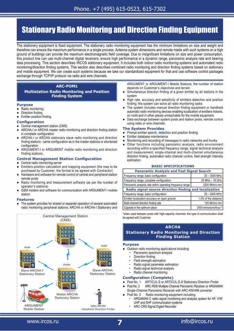
ARC-POM1Multistation Radio Monitoring and Position
Finding System
PurposeRadio monitoring ●Direction finding ●Emitter position finding. ●
ConfigurationCentral management station (CMS) ●ARCHA-I or ARCHA master radio monitoring and direction finding station ●in complete configuration ARCHA-I or ARCHA stationary slave radio monitoring and direction ●finding stations - same configuration as in the master stations or shortened configurationARGUMENT-I or ARGUMENT mobile radio monitoring and direction ●finding stations.
Central Management Station ConfigurationCentral radio monitoring server ●Emitters position calculation and mapping equipment (the map to be ●purchased by Customer; the format to be agreed with Contractor)Hardware and software for remote control of central and peripheral station ●remote postsRadio monitoring and measurement software (as per the number of ●operator’s stations)GSM modem and software for communication with ARGUMENT-I mobile ●station.
FeaturesThe system provides for shared or separate operation of several automated ●radio monitoring peripheral stations: ARCHA or ARCHA-I Stationary and
ARGUMENT or ARGUMENT-I Mobile Stations; the number of station depends on Customer’s objectives and terrain Simultaneous direction finding of a given emitter by all stations in the ●system High rate, accuracy and sensitivity of emitters detection and position ●finding; the system can solve all radio monitoring tasks. The system includes manual direction finding equipment or handheld ●automatic radio monitoring devices enabling localization of emitters indoors, on roofs and in other places unreachable for the mobile equipment. Data exchange between system posts and station posts, remote control ●using radio or wire channels.
The System ProvidesPrompt emitter search, detection and position finding ●Emitter database maintenance ●Monitoring and recording of messages in radio networks and trunks ●Other functions including panoramic analysis, radio environment ●recording within a specified frequency range, signal technical analysis and measurement, single-channel and multi-channel simultaneous direction finding, automated radio channel control, field strength intensity estimation.
BASIC SPECIFICATIONSPanoramic Analysis and Fast Signal Search
Frequency range, basic configuration 25 – 3000 MHzFrequency range, complete configuration 25 MHz – 18 GHzPanoramic analysis rate within operating frequency range 3200 MHz/s min Radio signal source direction finding and localization
Frequency range, basic configuration 25 – 3000 MHzEmitter localization accuracy on open ground 1.5% of the distanceMulti-channel direction finding rate 120 MHz/s min Capacity in the optimum place 2000 emissions/hour*
*when used between posts with high-capacity channels, the type of communication shall be agreed with Customer
ARCHAStationary Radio Monitoring and Direction
Finding Station
PurposeOutdoor radio monitoring applications including: ●
Panoramic spectrum analysis • Direction finding • Field strength estimation • Radio signal parameter estimation • Radio signal technical analysis • Radio channel monitoring.•
Configuration (Complete)Post No. 1 ARTICUL-S or ARTICUL-S-8 Stationary Direction Finder ●Post No. 2 ARC-RD6 Multiple-Channel Panoramic Receiver or ARGAMAK ●Single-Channel Panoramic Receiver with ARC-KNV4M converter Post No. 3 Radio monitoring equipment including: ●
ARGAMAK-C radio signal monitoring and analysis system for HF, VHF, • UHF and SHF communication systems ARC-CRS Signal Digital Recorder •
Stationary Radio Monitoring and Direction Finding EquipmentThe stationary equipment is fixed equipment. The stationary radio monitoring equipment has the minimum limitations on size and weight and therefore can ensure the maximum performance in a single process. Antenna system dimensions and remote masts with such systems on a high ground of buildings can provide the maximum electromagnetic field coverage. Due to insignificant limitations on size and power consumption, this product line can use multi-channel digital receivers, ensure high performance in a dynamic range, panoramic analysis rate and bearing data processing. This section describes IRCOS stationary equipment. It includes both indoor radio monitoring systems and automated radio monitoring/direction finding systems. This section also describes combined radio monitoring and direction finding systems based on stationary and mobile equipment. We can create such systems because we take our standardized equipment for that and use software control packages exchange through TCP/IP protocol via radio and wire channels.

Phone. +7 (495) 615-0523, 615-7302
www.ircos.ru [email protected]
Post No. 4 ARK-KN1 or ARK-KN2 Navigation Equipment. ●Common system equipment: ●
Interstation data exchange equipment • ARC-RP3 or ARC-RP3M Handheld Direction Finder.•
The abridged configuration includes just post No. 1. This post can handle all tasks intended for posts from 1 to 4 including radio emitters’ localization and their electronic mapping.Features
The station can function as a part of ARM-POM1 multi-channel position ●finding systems The station includes manual direction finding equipment or handheld ●automatic radio monitoring devices enabling localization of emitters indoors, on roofs and in other places unreacheable for the mobile equipment. Remote control and data exchange between stations by means of fiber ●optic lines, wire channels and radio channels.
The Station ProvidesPanoramic analysis within the entire operating frequency range or within ●separate intervals, detection of changes in ambient electromagnetic conditions. Saving the radio environment to the hard drive within a specif ied ●frequency range. This procedure can function within a long period and is based on amplitude/frequency/bearing/time coordinates, unit location and the absolute time at the time of saving. New emit ters search, measurement and comparison against the ●database. Database maintenance, comparing of the recorded data with the ●references in the database. Single and mult i -channel direction f inding of radio signals with ●random modulation types and spectrum width. Automated radiophonic channel control, recording of demodulated ●signals and their service parameters (frequency, time, signal level, etc.). Radio signal technical analysis and parameters assessment. ●Demodulated signals playback. ●Control of standard radio faci l i t ies conversat ions (random and ●routine), recording and accumulation of data for further analysis. Emitters position finding and showing their locations in electronic map. ●
BASIC SPECIFICATIONS
Panoramic Analysis and Fast Signal Search
Operating frequency range of the basic set 25 – 3000 MHzFrequency range, complete configuration
Post No. 1• 25 – 8000 MHzPost No. 2• 9 kHz - 18 GHz
Rate in operating range Depends on receiver type
Single Channel and Multi-Channel Direction Finding
Direction finding method Correlative interferometerOperating azimuth 360°Operating frequency range of the basic set 25 – 3000 MHzFrequency range, complete configuration 25 – 8000 MHz
Single Channel and Multi-Channel Direction Finding
Multi-channel direction finding rate (up to 3 GHz)in basic configuration• 120 MHz/s min with ARC-S5Special Processor• 300 MHz/s min
Single-channel direction finding rate (up to 3 GHz)in basic configuration• 30 bearings/s min with ARC-S5Special Processor• 80 bearings/s min
Processed signal spectrum width ArbitraryField sensitivity depending on the signal frequency 1 - 25 μV/mInstrument accuracy (RMS) 1,5°Antenna system remote location range up to 100 m
Radio Signal Recording, Technical Analysis and Parameter Measurement
Processed frequency bandwidth / resolution
5 MHz/12 kHz, 250 kHz/500 Hz, 100 kHz/200 Hz, 50 kHz/200 Hz, 25 kHz/100 Hz, 12 kHz/50 Hz, 6 kHz/25 Hz
ARCHA Operator’s Workstation
AC-PP4 Antenna System on a Building’s Roof
EMITTERS LOCALIZAION window screenshot

Phone. +7 (495) 615-0523, 615-7302
www.ircos.ru [email protected]
BEARING Window Screenshot
ARTIKUL-SStationary Direction Finder
Direction finding techniques and equipment are protected by the RF patents
PurposeDirection finding ●Panoramic spectrum analysis ●Field strength estimation ●Radio signal parameter estimation ●Radio signal technical analysis ●Radio channel monitoring. ●
Basic ConfigurationAS-PP4 foldable antenna system with integrated two-channel tuner ●(based on ARC-PS5) for mounting on an arbitrary length mast ARC-ACO-M11 Two-Channel A/D Processing Unit based on ARC-CO5 ●module of ARGAMAK family HF cable between antenna system and ARC-ACO-M11, 50 m long (upon ●request, up to 100 m) PC and software packages ●Power unit. ●
OptionsARC-S5 Special Processor ●Power supply system with charger and battery ●ARC-KN1 or ARC-KN2 navigation equipment (digital maps to be purchased ●by the Customer and installed following the guidelines provided by the company)Communication equipment. ●
FeaturesRemote wireless control and data exchange via radio channels ●are suppor ted by the sof tware packs Direction f inder can function as a par t of ARCHA station. ●
Direction Finder ProvidesSingle and multi-channel direction finding of radio signals with random ●modulation types and spectrum width New emitters search, measurement and comparison against the database. ●Creation of databases, their extension and comparing of the recorded ●data with the references in the database. Recording of radio signals at IF in a vector form to a PC hard disk ●Panoramic search within the entire operating frequency range or within ●separate intervals under complex electromagnetic conditions, detection of changes in ambient electromagnetic conditions Recording the radio environment to the hard drive within a specified ●frequency range. This procedure can function within a long period and is based on amplitude/frequency/bearing/time coordinates, unit location and the absolute time at the time of saving. Signal technical analysis and measurement ●Demodulated signals playback ●Accumulation of data for further analysis in the post-processing mode, ●simultaneous recording of demodulated signals and their service parameters (frequency, time, signal level, etc.).
Displaying bearing in electronic map. ●BASIC SPECIFICATIONS
Panoramic Analysis and Fast Signal Search
Operating frequency range 25 – 3000 MHzRate in operating range 3200 MHz/s min Attenuators 0 - 30 dB with 2 dB incrementSingle signal dynamic range 110 dB minIntermodulation free dynamic range (3rd and 2nd order) 75 dB min
Single Channel and Multi-Channel Direction Finding
Direction finding method Correlative interferometerOperating azimuth 0° - 360°Operating frequency range 25 – 3000 MHzMulti-channel direction finding rate
in basic configuration• 120 MHz/s min with ARC-S5Special Processor• 300 MHz/s min
Single-channel direction finding ratein basic configuration• 30 bearings/s min with ARC-S5Special Processor• 80 bearings/s min
Processed signal minimum durationsingle (in basic configuration)• 30 mssingle (with ARC-S5 Special Processor)• 10 msrepeating pulse signal (with ARC-S5 Special • Processor) 1 ms
Processed emitter signal spectrum width Arbitrary
Figure 1 - Direction Finding Sensitivity vs. Frequency for AC-PP4 Antenna System of ARTIKIL-S (Typical Characteristic)
AC-PP4 Antenna System for ARTIKUL-S Direction Finder on a Building’s Roof
Phone. +7 (495) 615-0523, 615-7302
www.ircos.ru [email protected]
Single Channel and Multi-Channel Direction Finding
Field sensitivity depending on the signal frequency 1 - 10 μV/mInstrument accuracy (RMS) 1,5°Antenna system remote location range up to 100 m
Radio Channel Monitoring and Broadcast RecordingRate of channel switch with direction finding 30 channel/s min Receiver sensitivity in AM, FM (narrow) mode 0.8 - 1.5 μV
Types of recorded dataBearing, demodulated signals,
spectrograms, coordinates, time, time-based signal sampling at IF.
Radio Signal Recording, Technical Analysis and Parameter Measurement
Processed frequency bandwidth / resolution
5 MHz/12 kHz, 250 kHz/500 Hz, 100 kHz/200 Hz, 50 kHz/200 Hz, 25 kHz/100 Hz, 12 kHz/50 Hz, 6 kHz/25 Hz
*Field sensit ivity vs. f requency for ARTIKUL-C is shown on Figure 1. The direction finder has got a certificate of compliance No. 03.009.0403 and registered in instruments facultative registration system.
ARTIKUL-S-8Stationary Direction Finder
Direction finding techniques and equipment are protected by the RF patents
PurposeOutdoor radio monitoring applications including: ●
Direction finding • Panoramic spectrum analysis • Field strength estimation • Radio signal parameter estimation • Radio signal technical analysis • Radio channel monitoring.•
Basic Configuration:Mast-mounted AS-PP8 antenna system with an integral two-channel ●tuner (based on ARC-PS5 for 25-3000 MHz) and eight-channel frequency down-converter (based on ARC-KNV3 for 3000-8000 MHz)ARC-ACO-M11 Two-Channel A/D Processing Unit with ARC-S5 Special ●ProcessorLead-in cable between mast mounted antenna system and ARC-ACO-M11, ●50 m long (upon request, up to 100 m)PC and software packages ●Power unit. ●
OptionsARC-KN2 Navigation Equipment (digital maps to be purchased by the Customer ●and installed following the guidelines provided by the company)Communication equipment. ●
FeaturesRemote wireless control and data exchange via radio channels are ●supported by the software packsDirection finder can function as a part of ARCHA station. ●
Direction Finder ProvidesNew emit ters search, measurement and comparison against the ●databaseCreation of databases, their extension and comparing of the recorded ●data with the references in the databaseRecording radio signals in a vector form to a PC hard disk ●Panoramic search within the entire operating frequency range or ●within separate intervals under complex electromagnetic conditions, detection of changes in ambient electromagnetic conditionsRecording the radio environment to the hard drive within a specified ●frequency range. This procedure can function within a long period and is based on amplitude/frequency/bearing/time coordinates, unit location and the absolute time at the time of savingSingle and multi-channel direction finding of radio signals with random ●modulation types and spectrum widthSignal technical analysis and measurement ●
Demodulated signals playback ●Accumulation of data for further analysis in the post-processing mode, ●simultaneous recording of demodulated signals and their service parameters (frequency, time, signal level, etc.)Displaying bearing in electronic map. ●
BASIC SPECIFICATIONSPanoramic Analysis and Fast Signal Search
Operating frequency range 25 – 8000 MHzRate in operating range 3200 MHz/sAttenuators 0 - 30 dB with 2 dB incrementSingle signal dynamic range 110 dBIntermodulation free dynamic range (3rd and 2nd order) 75 dB
Single Channel and Multi-Channel Direction FindingDirection finding method Correlative interferometerOperating azimuth 0°- 360°Operating frequency range 25 – 8000 MHzMulti-channel direction finding rate
25 – 3000 MHz• 300 MHz/s3 - 8 GHZ• 75 MHz/s
Single-channel direction finding rate25 – 3000 MHz• 80 bearing/s3 - 8 GHZ• 20 bearing/s
Repeating pulse signal with min. unit interval 1 msProcessed signal minimum duration
25 – 3000 MHz• 10 ms3 - 8 GHZ• 30 ms
Processed signal spectrum width ArbitraryField sensitivity depending on the signal frequency 1 - 25 μV/mInstrument accuracy (RMS) 1.5°Antenna system remote location range up to 100 mDimensions:
Dimensions (diameter x height)• 2500 x 2100 mmAnalogue-digital processing unit (ADPU)• 462 x 141 x 266 mm
Antenna system weight 60 kgAnalogue-digital processing unit weight 8 kg
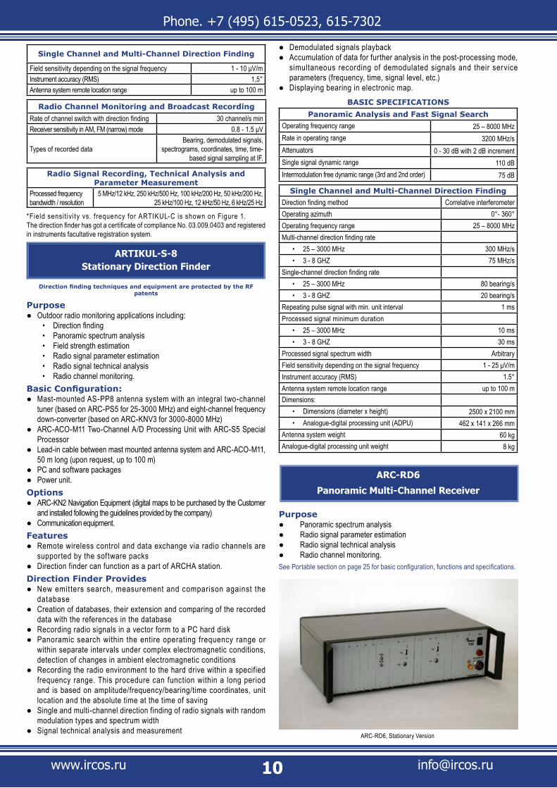
ARC-RD6
Panoramic Multi-Channel Receiver
Purpose Panoramic spectrum analysis ● Radio signal parameter estimation ● Radio signal technical analysis ● Radio channel monitoring. ●
See Portable section on page 25 for basic configuration, functions and specifications.
ARC-RD6, Stationary Version

Phone. +7 (495) 615-0523, 615-7302
www.ircos.ru [email protected]
ARC-POM2Multistation Radio Monitoring and Position
Finding System
PurposeRadio monitoring ●Direction finding ●Emitter position finding. ●
ConfigurationARGUMENT or ARGUMENT-I master station in complete configuration ●ARGUMENT or ARGUMENT-I mobile slave stations - same configuration ●as in the master stations or shortened configuration.
FeaturesJoint or individual operation of several remote ARGUMENT Mobile ●Stations. The number of stations in the system is taken based on Customer tasks and terrain Simultaneous direction finding of a given emitter by all stations in the system ●The central station may be any station included in the system ●High rate, accuracy and sensitivity of emitters detection and position ●finding Can handle all radio monitoring tasks ●The system includes manual direction finding equipment and portable ●automatic radio monitoring devices enabling localization of emitters indoors, on roofs and in other places unreachable for the mobile equipment Data exchange between system posts and station posts, remote radio ●channel control.
The System ProvidesPrompt emitter search, detection and position finding. ●Emitter database maintenance ●Other functions including panoramic analysis, radio environment ●recording within a specif ied frequency, signal technical analysis and measurement, single-channel and multi-channel simultaneous direction f inding, automated radio channel control, f ield strength intensity estimation.
System specifications are determined by system equipment parameters.
ARGUMENTMobile Radio Monitoring and Direction Finding
Station
For government agencies only
PurposeOutdoor radio monitoring applications including: ●
Panoramic spectrum analysis• Direction finding • Radio transmitters localization• Field strength estimation• Radio signal parameter measurement• Radio signal technical analysis• Radio channel monitoring.•
Complete configurationPost No. 1. ARTICUL-M Mobile Direction Finder with two antenna systems: ●mounted on a vehicle roof and on a remote mastPost No. 2. ARC-RD6 Multi-Channel Panoramic Receiver or ARGAMAK-K ●Single-Channel Panoramic Receiver with ARC-KNV4M Frequency Down-ConverterPost No. 3. Radio monitoring equipment including: ●
ARGAMAK-C radio signal monitoring and analysis system for HF, • VHF, UHF and SHF communication systemsARC-CRS Signal Digital Recorder•
Post No. 4: ARK-KN1 or ARK-KN2 Navigation Equipment ●Common system equipment: ●
Equipment for data transmission to other stations • ARC-RP3 or ARC-RP3M Handheld Direction Finder, or ARC-NK3I • Measuring SystemSelf-contained power supply.•
The Shorted Configuration includes just post No. 1. This post can handle all tasks intended for the posts from 1 to 4 including radio emitters’ localization and their electronic mapping.Features
This station can function as a part of ARC-POM2 and ARM-POM1 multi- ●station Localization systemsThe station includes manual direction finding equipment or handheld ●automatic radio monitoring devices enabling localization of emitters indoors, on roofs and in other places unreacheable for the mobile equipmentThe data exchange and control are ensured through a LAN between all ●station postsThe software enables effective operation in a rapidly fluctuating radio ●environment as well as prompt adaptation to its changes.
The Station ProvidesNew emit ters search, measurement and comparison against the ●databaseAutomatic position finding and e-mapping of emitters both in real time ●and in postprocessing modePanoramic search within the entire operating frequency range or within ●
Mobile Radio Monitoring and Direction Finding Equipment
Mobile radio monitoring equipment can be permanently or temporarily installed on a vehicle or an aircraft and can perform their functions on the move. Besides, they can be powered from supplies installed on the same vehicle. The mobile radio monitoring equipment has small limitations on size and weight and therefore can perform very effectively. Antenna system dimensions and remote masts with such systems on a high ground can ensure the maximum electromagnetic field coverage. Due to insignificant limitations on size and power consumption, this product line can use multi-channel digital panoramic receivers, ensure high performance in a dynamic range, panoramic analysis rate and bearing data processing. This section describes IRCOS mobile equipment. The equipment can differ in sophistication level, performance figures and price. Their functions and configuration can be modified according to Customer request. This section also describes combined radio monitoring and direction finding systems based on portable and handheld equipment. We can create such systems because we take our standardized equipment for that and use software control packets exchange through TCP/IP protocol via radio channels.

Phone. +7 (495) 615-0523, 615-7302
www.ircos.ru [email protected]
separate intervals under complex electromagnetic conditions, detection of its changes Recording the radio environment to the hard drive within a specified ●frequency range. This procedure can function within a long period and is based on amplitude/frequency/bearing/time coordinates, unit location and the absolute time at the time of saving. Database maintenance ●Single and multi-channel direction finding of radio signals with random ●modulation types and spectrum widthAutomatic radiophonic channel monitoring within specific range sections ●and/or fixed frequencies, simultaneous recording of demodulated signals and their service parametersTechnical analysis of radio signals in real time mode and in postprocessing ●modeDemodulated signals playback ●Accumulation of data for further analysis in the postprocessing mode ●Station coordinate and course finding, showing station path in the map ●both in real-time mode and postprocessing modeField strength estimation and its distribution mapping ●Showing emitters in spatially distributed locations ●Evaluation of field strength distribution around emitters subject to terrain ●and displaying field strength in the mapMapping field strength distribution calculated based on measurement ●resultsLocalization of emitters based on field strength measurement ●Verification of emitter parameters including its coordinates and power ●based on field strength measurement.
Station Post FunctionsPost No. 1:
Single-channel and multi-channel direction finding ●Search for new emitters ●Panoramic analysis within operating frequency range ●
Radio environment recording within a specified frequency range based on ●amplitude/frequency/bearing/time coordinates Recording radio signals to the hard drive, their technical analysis and ●parameter measurement Automated monitoring of detected radio channels ●Sending operational information through a LAN to the other posts for ●further entry to the database.
Post No. 1 is intended for customized tasks. If the number of posts is limited (e.g. when posts No.2-4 are not available) their tasks can be handled using just post No. 1.Post No. 2:
Field strength evaluation ●Search for new emitters ●Sending operational information through a LAN to the other posts for its ●further entry to the database and task setting Panoramic analysis within operating frequency range ●Radio environment recording within a specified frequency range based on ●amplitude/frequency/time coordinates Recording radio signals to the hard drive, their technical analysis and ●parameter measurement Automated monitoring of detected radio channels. ●
Post No. 2 is primarily intended for detection of new emitters. When a new emission is detected, this post generates top priority commands and sends them to post No 1 (detection finding) and post No. 3 (multi-channel control). Post No. 2 has no limitations on task/mode changing.Post No. 3:
Panoramic analysis and quick search for new signals ●Radio signal spectrum displaying, calculation of spectrum, level and band ●of received signals Tuning for the set frequency ●Demodulated signal listening ●Recording radio signals in a vector form to a PC hard disk ●Technical analysis of radio signals in real time and in postprocessing ●mode Emitters identification and classification, more than 60 types ●Technical analysis and demodulation of radio emission fragments; types: ●AM, WFM, NFM, LSSB, USSB, FSK2, FSK4, FSK6, FSK8, FSK12, FSK16, FSK32, MFSK, PSK2, PSK4, PSK8, QAM16, QAM32, QAM64, QAM128, DQPSKStatus and capacity indication for each of the two drives ●Recording radio signals either to *.taf file (at the carrier frequency in a ●vector form) or to *.wav file (at the subcarrier frequency) Digital streams structure/time analysis in a great variety of protocols and ●standards both in real time and in post-processing mode.
Operator of post No. 3 performs the tasks from post No. 1 or 2 or on his/her own.Post No. 4:
Emitter position finding ●
ARGUMENT Station on Gazel Van with AC-MP6 Stationary Antenna System
Station Process Section with folded AC-PP4 antennaOperator’s Workstation
ARGUMENT Station on Hyundai Van with AC-MP17 Removable Antenna System and AC-PP17 Remote Antenna System

Phone. +7 (495) 615-0523, 615-7302
www.ircos.ru [email protected]
Emitters Finding on the Move - SMO-KN Software Screenshot
Showing bearings and emitters in electronic map ●Field strength distribution mapping based on measurements ●Evaluation of field strength distribution around emitters subject to terrain ●and displaying field strength in the map Showing emitters in spatially distributed locations ●Forming and maintenance of emitter database structure ●Collecting and processing of radio channel monitoring data ●Tasks/data transmission to slave stations ●Data acquisition from slave stations ●Database management (archivation, recovery, filtering, etc.) ●Report (incl. graphical report) generation and printout ●Localization data acquisition ●Showing carrier's current position and path. ●
BASIC SPECIFICATIONS
Panoramic Analysis and Fast Signal Search
Operating frequency range of the basic set 25 – 3000 MHzFrequency range, complete configuration
Post No. 1• 25 – 3000 MHzPost No. 2• 9 kHz - 18 GHz
Panoramic analysis rate within operating frequency range
Post No. 1 • 3200 MHz/s min Post No. 2• 600 MHz/s min Post No. 3 (depends on digital receiver type)• up to 20 GHz/s
Intermodulation free dynamic range (3rd and 2nd order) 75 dB
Single Channel and Multi-Channel Direction Finding
Direction finding method Correlative interferometer
Operating azimuth 0° - 360°
Single Channel and Multi-Channel Direction Finding
Operating frequency range 25 – 3000 MHz
Multi-channel direction finding rate
in basic configuration• 120 MHz/s
with ARC-S5Special Processor• 300 MHz/s
Single-channel direction finding rate
in basic configuration• 30 bearing/s
with ARC-S5Special Processor• 80 bearing/s
Processed signal spectrum width Arbitrary
Processed signal minimum duration
single (in basic configuration)• 30 ms
single (with ARC-S5 Special Processor)• 10 msrepeating pulse signal (with ARC-S5 Special • Processor) 1 ms
Instrument accuracy (RMS) for antenna system:
Vehicle-mounted• 2,5°
Mast-mounted• 1,5°Field sensitivity for antenna systems (depending on the signal frequency):
Vehicle-mounted• 2 - 10 μV/m
Mast-mounted• 1 - 8 μV/m
Antenna system remote location range up to 100 m
Radio Channel Monitoring and Broadcast Recording
Number of simultaneously monitored channels up to 10
Receiver sensitivity in AM, FM (narrow) mode 0.8 - 1.5 μV
Types of recorded dataBearing, demodulated signals,
spectrograms, coordinates, time, time-based signal sampling at IF.
Radio Signal Recording, Technical Analysis and Parameter Measurement
Processed frequency bandwidth / resolution
5 MHz/12 kHz, 250 kHz/500 Hz, 100 kHz/200 Hz, 50 kHz/200 Hz, 25 kHz/100 Hz, 12 kHz/50 Hz, 6 kHz/25 Hz
ARTIKUL-MMobile Direction Finder with Two Antenna
Systems
Direction finding techniques and equipment are protected by the RF patents
PurposeOutdoor radio monitoring applications including: ●
Direction finding • Radio transmitters localization• Panoramic spectrum analysis• Field strength estimation• Radio signal parameter estimation• Radio signal technical analysis• Radio channel monitoring• .
Basic ConfigurationAC-MP1 or AC-MP17 Antenna System for mounting on a vehicle roof ●AS-PP4 or AS-PP17 antenna system with integrated two-channel tuner ●(based on ARC-PS5) for mounting on a mastARC-ACO-M11 To-Channel A/D Processing Unit based on ARC-CO5 ●module of ARGAMAK family Lead-in cable, 25 m long (upon request, up to 100 m) ●PC and software packages ●
Operator’s Station and Baggage Section of Hyundai-Mounted ARGUMENT Station with AC-PP17 Folded Antenna System
Phone. +7 (495) 615-0523, 615-7302
www.ircos.ru [email protected]
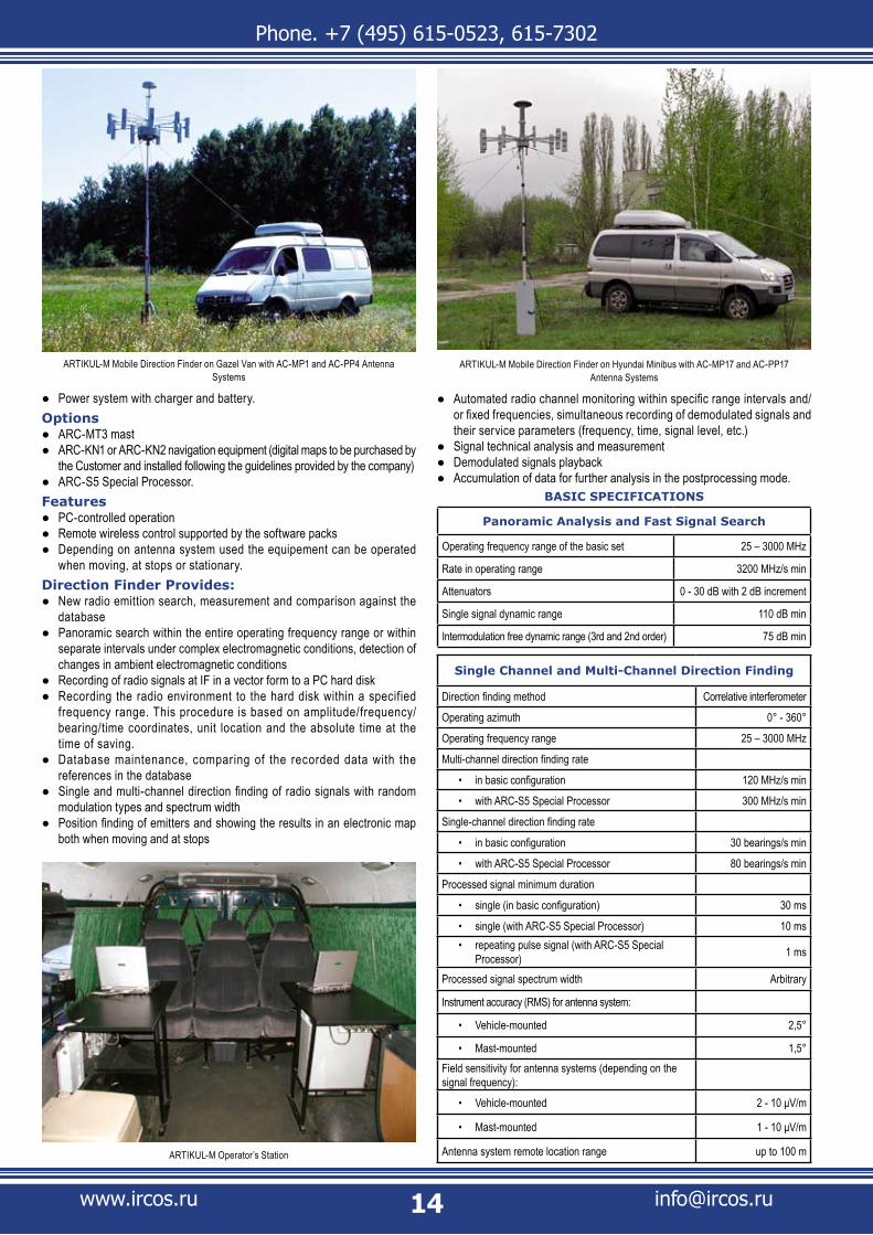
Power system with charger and battery. ●Options
ARC-MT3 mast ●ARC-KN1 or ARC-KN2 navigation equipment (digital maps to be purchased by ●the Customer and installed following the guidelines provided by the company)ARC-S5 Special Processor. ●
FeaturesPC-controlled operation ●Remote wireless control supported by the software packs ●Depending on antenna system used the equipement can be operated ●when moving, at stops or stationary.
Direction Finder Provides:New radio emittion search, measurement and comparison against the ●database Panoramic search within the entire operating frequency range or within ●separate intervals under complex electromagnetic conditions, detection of changes in ambient electromagnetic conditions Recording of radio signals at IF in a vector form to a PC hard disk ●Recording the radio environment to the hard disk within a specified ●frequency range. This procedure is based on amplitude/frequency/bearing/time coordinates, unit location and the absolute time at the time of saving. Database maintenance, comparing of the recorded data with the ●references in the database Single and multi-channel direction finding of radio signals with random ●modulation types and spectrum width Position finding of emitters and showing the results in an electronic map ●both when moving and at stops
Automated radio channel monitoring within specific range intervals and/ ●or fixed frequencies, simultaneous recording of demodulated signals and their service parameters (frequency, time, signal level, etc.) Signal technical analysis and measurement ●Demodulated signals playback ●Accumulation of data for further analysis in the postprocessing mode. ●
BASIC SPECIFICATIONS
Panoramic Analysis and Fast Signal Search
Operating frequency range of the basic set 25 – 3000 MHz
Rate in operating range 3200 MHz/s min
Attenuators 0 - 30 dB with 2 dB increment
Single signal dynamic range 110 dB min
Intermodulation free dynamic range (3rd and 2nd order) 75 dB min
Single Channel and Multi-Channel Direction Finding
Direction finding method Correlative interferometer
Operating azimuth 0° - 360°
Operating frequency range 25 – 3000 MHz
Multi-channel direction finding rate
in basic configuration• 120 MHz/s min
with ARC-S5 Special Processor• 300 MHz/s min
Single-channel direction finding rate
in basic configuration• 30 bearings/s min
with ARC-S5 Special Processor• 80 bearings/s min
Processed signal minimum duration
single (in basic configuration)• 30 ms
single (with ARC-S5 Special Processor)• 10 msrepeating pulse signal (with ARC-S5 Special • Processor) 1 ms
Processed signal spectrum width Arbitrary
Instrument accuracy (RMS) for antenna system:
Vehicle-mounted• 2,5°
Mast-mounted• 1,5°Field sensitivity for antenna systems (depending on the signal frequency):
Vehicle-mounted• 2 - 10 μV/m
Mast-mounted• 1 - 10 μV/m
Antenna system remote location range up to 100 m
ARTIKUL-M Mobile Direction Finder on Hyundai Minibus with AC-MP17 and AC-PP17 Antenna Systems
ARTIKUL-M Operator’s Station
ARTIKUL-M Mobile Direction Finder on Gazel Van with AC-MP1 and AC-PP4 Antenna Systems

Phone. +7 (495) 615-0523, 615-7302
www.ircos.ru [email protected]
Radio Channel Monitoring and Broadcast Recording
Receiver sensitivity in AM, FM (narrow) mode 0.8 - 1.5 μV
Types of recorded dataBearing, demodulated signals,
spectrograms, coordinates, time, time-based signal sampling at IF.
Radio Signal Recording, Technical Analysis and Parameter Measurement
Processed frequency bandwidth / resolution
5 MHz/12 kHz, 250 kHz/500 Hz, 100 kHz/200 Hz, 50 kHz/200 Hz, 25 kHz/100 Hz, 12 kHz/50 Hz, 6 kHz/25 Hz
*Field sensitivity/frequency dependencies for AC-MP1, AC-MP17, AC-PP4 and AC-PP17 are shown on Figures 1-5.
ARTIKUL-M1Mobile Direction Finder
Direction finding techniques and equipment are protected by the RF patents
PurposeOutdoor radio monitoring applications including: ●
Direction finding • Radio transmitters localization• Panoramic spectrum analysis• Field strength estimation• Radio signal parameter estimation• Radio signal technical analysis• Radio channel monitoring.•
Basic ConfigurationRemovable, AS-MP1 or AS-MP17 Antenna System: ●Two-channel tuner based on ARC-PS5 of ARGAMAK family ●ARC-ACO-M11 Two-Channel A/D Processing Unit based on ARC-CO5 ●module of ARGAMAK family PC and software packages ●Power system with charger and battery. ●
OptionsARC-S5 Special Processor ●ARC-KN1 or ARC-KN2 navigation equipment (digital maps to be ●purchased by the Customer and installed following the guidelines provided by the company)Communication equipment. ●
FeaturesMounting - AS-MP1 (AS-MP17) antenna system is removable. It can be ●removed and mounted back onto a vehicle roof.Remote wireless control supported by the software packs ●
Can operate on the move and at stops ●Can function as a part of ARGUMENT Station. ●
The direction finder has got a certificate of compliance No. 03.009.0403 and registered in instruments facultative registration system.Direction Finders Provide
New emitters search, measurement and comparison against the database ●Single and mult i -channel direction f inding of radio signals with ●random modulation types and spectrum width Panoramic search within the entire operating frequency range or ●within separate intervals under complex electromagnetic conditions, detection of changes in ambient electromagnetic conditions Recording the radio environment to the hard drive within a specified ●frequency range. This procedure can function within a long period and is based on amplitude/frequency/bearing/time coordinates, unit location and the absolute time at the time of saving Database maintenance, comparing of the recorded data with the ●references in the database Position finding of emitters and showing the results in an electronic ●map both when moving and at stops Recording radio signals at IF in a vector form to a PC hard disk for ●postprocessing Signal technical analysis and measurement ●Demodulated signals playback ●Accumulation of data for further analysis in the postprocessing mode. ●
BASIC SPECIFICATIONS
Panoramic Analysis and Fast Signal Search
Operating frequency range of the basic set 25 – 3000 MHz
Rate in operating range 3200 MHz/s min
Attenuators 0 - 30 dB with 2 dB increment
Single signal dynamic range 110 dB min
Intermodulation free dynamic range (3rd and 2nd order) 75 dB min
Single Channel and Multi-Channel Direction Finding
Direction finding method Correlative interferometer
Operating azimuth 0° - 360°
Operating frequency range 25 – 3000 MHz
Multi-channel direction finding rate
in basic configuration• 120 MHz/s min
with ARC-S5Special Processor• 300 MHz/s min
Single-channel direction finding rate
in basic configuration• 30 bearings/s min
with ARC-S5Special Processor• 80 bearings/s min
ARTIKUL-M1 Mobile Direction Finder on a Minibus with AC-MP1
ARTIKUL-M1 Mobile Direction Finder on an AWD Vehicle with AC-MP17

Phone. +7 (495) 615-0523, 615-7302
www.ircos.ru [email protected]
Single Channel and Multi-Channel Direction Finding
Processed signal spectrum width Arbitrary
Processed signal minimum duration
single (in basic configuration)• 30 ms
single (with ARC-S5 Special Processor)• 10 msrepeating pulse signal (with ARC-S5 Special • Processor) 1 ms
Instrument accuracy (RMS) 2.5°
Field sensitivity for antenna systems (depending on the signal frequency): 2 - 10 μV/m
Radio Channel Monitoring and Broadcast Recording
Rate of channel switch with direction finding 30 channel/s min
Receiver sensitivity in AM, FM (narrow) mode 0.8 - 1.5 μV
Types of recorded dataBearing, demodulated signals,
spectrograms, coordinates, time, time-based signal sampling at IF.
Radio Signal Recording, Technical Analysis and Parameter Measurement
Processed frequency bandwidth / resolution
5 MHz/12 kHz, 250 kHz/500 Hz, 100 kHz/200 Hz, 50 kHz/200 Hz, 25 kHz/100 Hz, 12 kHz/50 Hz, 6 kHz/25 Hz
*Field sensitivity/frequency dependencies for ARTIKUL-M1 with AC-MP1/AC-MP17 antenna system are shown on diagram 2-3
ARTIKUL-M4Mobile Direction Finder
For government agencies only
Direction finding techniques and equipment are protected by the RF patents
PurposeOutdoor radio monitoring applications including: ●
Direction finding • Panoramic spectrum analysis• Field strength estimation• Radio signal parameter estimation• Radio signal technical analysis• Radio channel monitoring.•
Basic ConfigurationFoldable AS-PP4 or AS-PP17 antenna system with integrated two- ●channel tuner (based on ARC-PS5) for mounting on a mast, arbitrary height ARC -ACO - M11 Two - Channe l A /D Process ing Uni t based on ●ARC-CO5 module of ARGAMAK family HF cable between antenna system and ARC-ACO-M11, 25 m long ●(upon request, up to 100 m) PC and software packages ●Power unit. ●
OptionsARC-S5 Special Processor ●Power supply system with charger and battery ●ARC-KN1 or ARC-KN2 navigation equipment (digital maps to be purchased ●by the Customer and installed following the guidelines provided by the company)Communication equipment. ●
FeaturesRemote wireless control and data exchange via radio channels • are supported by the software packs Direction f inder is operated at stops or as a f ixed unit • May be included into:• ARGUMENT Mobile Radio Monitor ing and Direction Finding • Station for operation at stops
ARTIKUL-M4 Mobile Direction Finder with AC-PP4 Antenna SystemFigure 3 - Direction Finding Sensitivity vs. Frequency for AC-MP1 Antenna System (Typical Characteristic)
Figure 2 - Direction Finding Sensitivity vs. Frequency for AC-MP1 Antenna System (Typical Characteristic)

Phone. +7 (495) 615-0523, 615-7302
www.ircos.ru [email protected]
ARCHA Stationary Station.•
Direction Finder ProvidesNew emitters search, measurement and comparison against the database. ●Creation of databases, their extension and comparing of the recorded ●data with the references in the database. Recording of radio signals at IF in a vector form to a PC hard disk ●Panoramic search within the ent ire operat ing f requency range ●or w i th in separate in ter va ls under complex e lec t romagnet ic condi t ions, detect ion of changes in ambient e lec t romagnet ic condi t ions Record ing the rad io env i ronment to the hard dr ive w i th in a ●specif ied f requency range. This procedure can funct ion within a long period and is based on amplitude/frequency/bearing/time coordinates, unit locat ion and the absolute t ime at the t ime of saving. Single and multi-channel direction finding of radio signals with random ●modulation types and spectrum width Signal technical analysis and measurement ●Demodulated signals playback ●Accumulation of data for fur ther analysis in the post-processing ●mode, simultaneous recording of demodulated signals and their service parameters (frequency, t ime, signal level, etc.). Displaying bearing in electronic map. ●
BASIC SPECIFICATIONS
Panoramic Analysis and Fast Signal Search
Operating frequency range 25 – 3000 MHz
Rate in operating range 3200 MHz/s min
Attenuators 0 - 30 dB with 2 dB increment
Single signal dynamic range 110 dB min
Intermodulation free dynamic range (3rd and 2nd order) 75 dB min
Single Channel and Multi-Channel Direction Finding
Direction finding method Correlative interferometer
Operating frequency range 25 – 3000 MHz
Multi-channel direction finding rate
in basic configuration• 120 MHz/s min
with ARC-S5Special Processor• 300 MHz/s min
Single Channel and Multi-Channel Direction Finding
Operating azimuth 0° - 360°
Single-channel direction finding rate
in basic configuration• 30 bearings/s min
with ARC-S5Special Processor• 80 bearings/s min
Processed signal minimum duration
single (in basic configuration)• 30 ms
single (with ARC-S5 Special Processor)• 10 ms
repeating pulse signal (with ARC-S5 Special • Processor) 1 ms
Processed emitter signal spectrum width Arbitrary
Field sensitivity (depending on the signal frequency)¬ 1 - 8 μV/m
Instrument accuracy (RMS) 1,5°
Antenna system remote location range up to 100 m
Radio Channel Monitoring and Broadcast Recording
Rate of channel switch with direction finding 30 channel/s min
Receiver sensitivity in AM, FM (narrow) mode 0.8 - 1.5 μV
Types of recorded dataBearing, demodulated signals,
spectrograms, coordinates, time, time-based signal sampling at IF.
Radio Signal Recording, Technical Analysis and Parameter Measurement
Processed frequency bandwidth / resolution
5 MHz/12 kHz, 250 kHz/500 Hz, 100 kHz/200 Hz, 50 kHz/200 Hz, 25 kHz/100 Hz, 12 kHz/50 Hz, 6 kHz/25 Hz
*Field sensit ivity vs. f requency for ARTIKUL-M4 Direct ion Finder is shown on Fig. 4.
Figure 4 - Direction Finding Sensitivity vs. Frequency for AC-PP4 Antenna System of ARTIKUL-M4 Mobile Direction Finder (with 0.8 m Antenna Radius) - Typical CharacteristicARTIKUL-M4 Mobile Direction Finder with AC-PP17 Antenna System

Phone. +7 (495) 615-0523, 615-7302
www.ircos.ru [email protected]
ARC-POM3Portable Multistation Radio Monitoring and
Position Finding System
PurposeRadio monitoring ●Direction finding ●Emitter position finding. ●
ConfigurationCentral ARENA Portable Radio Monitoring and Direction Finding Station ●in complete configurationPeripheral ARENA Portable Radio Monitoring and Direction Finding ●Station - in shortened or in the same configuration as above.
FeaturesJoint or individual operation of several remote ARENA Portable Stations ●Simultaneous direction finding of a given emitter by all portable stations ●in the systemCan handle all radio monitoring tasks ●Includes manual direction finding equipment enabling a more precise ●emitter scanningData exchange between system posts, remote radio channel control. ●
BASIC SPECIFICATIONS
Emitter localization accuracy on open ground 2% of the distance
Other specifications depend on ARENA station parameters.
ARC-PST (ARENA)Portable Radio Monitoring and Direction Finding
Station
PurposeOutdoor radio monitoring applications including: ●
Panoramic spectrum analysis• Direction finding • Estimation of electromagnetic f ield strength and radio signal • parametersRadio signal technical analysis• Radio channel monitoring. •
ConfigurationARTIKUL-P automatic direction finder ●PC and software packages ●ARC-KN1 or ARC-KN2 navigation equipment (digital maps to be purchased by ●the Customer and installed following the guidelines provided by the company) Backpacks ●Digital communication and inter-post exchange system ●Power system ●Operation documents. ●
OptionsHandheld direction finder – ARC-RP3 or ARC-RP3M ●Antenna system mast (up to 12 meters high) ●Self-contained portable power generator ●Solar battery set. ●
FeaturesIntended for operation at stops. ●
The Station ProvidesNew emitters search, measurement and comparison against the database. ●Panoramic analysis within the entire operating frequency range or ●within separate intervals in complicated electromagnetic environment, accommodation to ambient radio environment and detection of its changes.Saving the radio environment to the hard disk within a specified frequency ●range. This procedure is based on amplitude/frequency/bearing/time coordinates, post location and the absolute time at the moment of saving.Multi-channel and singe-channel direction finding of radio signals with ●random modulation types and spectrum width Creation of databases, their extension and comparing of the recorded ●data with the references in the database. Automated radio channel monitoring within specif ic range intervals ●and/or f ixed frequencies, simultaneous recording of demodulated signals and their service parameters (frequency, time, signal level, etc.)
Portable Radio Monitoring and Direction Finding Equipment
The portable automated radio monitoring equipment can be carried by one or several operators. This equipment can be deployed in stationary posts, temporary posts and on the open ground. The equipment is not intended for functioning on the move. There are some limitations on the weight, power consumption and dimensions. The portable equipment, when necessary, can be powered from a standalone power supply. This section describes IRCOS portable equipment: Multi-functional outdoor/indoor radio monitoring systems and portable direction finders.
ARENA as the Master Station in ARC-POM3 System
ARENA as a Slave Station in ARC-POM3 System
Phone. +7 (495) 615-0523, 615-7302
www.ircos.ru [email protected]
Radio signal technical analysis and parameters assessment. ●Demodulated signals playback ●Data recording and storing for further analysis. ●
Station specifications are determined by parameters of ARTIKUL-P portable direction finder.
ARTIKUL-PPortable Automatic Direction Finder
Direction finding techniques and equipment are protected by the RF patents.
First Grade medal awarded by the XII Moscow International Forum & Exhibition «Security and Safety
Technologies» (2007)
Security & Quality medal awarded by National Security International Contest (2006)
PurposeOutdoor radio monitoring applications including: ●
Panoramic spectrum analysis• Direction finding • Estimation of electromagnetic field strength and radio signal parameters• Radio signal technical analysis• Radio channel monitoring.•
Basic ConfigurationAS-PP17-1 (25 – 1000 MHz) or AS-PP17 (25 – 3000 MHz) Foldable ●Antenna System with integrated tuners based on ARC-PS5Telescopic mast (up to 4 meters high) ●ARC-KS17 System Case, comprising: ●
ARC-ACO-M11 Two-Channel Digital Processing Unit• Powered from AC network, vehicle battery or external battery• AC charger for external battery •
Lead-in cable between AS-PP17-1 and system case, 25 m long (upon ●request, up to 50 m) Antenna system and mast transportation tube ●Backpacks. ●
OptionsARC-KN2 Navigation Equipment (digital maps to be purchased by the ●Customer and installed following the guidelines provided by the company) PC and software packages. ●
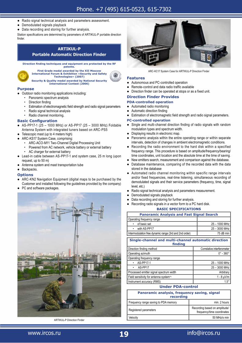
FeaturesAutonomous and PC-controlled operation ●Remote-control and data radio traffic available ●Direction finder can be operated at stops or as a fixed unit. ●
Direction Finder ProvidesPDA-controlled operation
Automated radio monitoring ●Automatic direction finding ●Estimation of electromagnetic field strength and radio signal parameters. ●
PC-controlled operationSingle and multi-channel direction finding of radio signals with random ●modulation types and spectrum width.Displaying results in electronic map. ●Panoramic analysis within the entire operating range or within separate ●intervals, detection of changes in ambient electromagnetic conditions.Recording the radio environment to the hard disk within a specified ●frequency range. This procedure is based on amplitude/frequency/bearing/time coordinates, unit location and the absolute time at the time of saving.New emitters search, measurement and comparison against the database. ●Database maintenance, comparing of the recorded data with the data ●stored in the databaseAutomated radio channel monitoring within specif ic range intervals ●and/or fixed frequencies, real-time listening, simultaneous recording of demodulated signals and their service parameters (frequency, time, signal level, etc.)Radio signal technical analysis and parameters measurement. ●Demodulated signals playback ●Data recording and storing for further analysis. ●Recording radio signals in a vector form to a PC hard disk. ●
BASIC SPECIFICATIONS
Panoramic Analysis and Fast Signal SearchOperating frequency range
of basic set• 25 – 1000 MHzwith AS-PP17• 25 – 3000 MHz
Intermodulation free dynamic range (3rd and 2nd order) 75 dB min
Single-channel and multi-channel automatic direction finding
Direction finding method Correlative interferometerOperating azimuth 0° - 360°Operating frequency range
AS-PP17-1• 25 – 1000 MHz AS-PP17• 25 – 3000 MHz
Processed emitter signal spectrum width ArbitraryField sensitivity for antenna system¬ 1 - 8 μV/mInstrument accuracy (RMS) 1.5°
Under PDA-controlPanoramic analysis, frequency saving, signal
recording
Frequency range saving to PDA memory min. 2 hours
Registered parameters Recording based on amplitude/frequency/time coordinates
Velocity 50 MHz/s min
ARC-KC17 System Case for ARTIKUL-P Direction Finder
ARTIKUL-P Direction Finder
Phone. +7 (495) 615-0523, 615-7302
www.ircos.ru [email protected]
Spectrum displaying modes Normal / Average / PeakReceiver frequency tuning display DigitalSignal spectrum band indication DigitalSignal level display Graphic and digital
Under PC ControlPanoramic Analysis and Fast Signal Search
Rate in operating frequency range 3200 MHz/s min Single Channel and Multi-Channel Direction Finding
Multi-channel direction finding rateof basic set• 120 MHz/s min with ARC-S5Special Processor• 300 MHz/s min
Single-channel direction finding ratein basic configuration• 30 bearings/s min with ARC-S5Special Processor• 80 bearings/s min
Processed signal minimum durationsingle (in basic configuration)• 30 mssingle (with ARC-S5 Special Processor)• 10 msrepeating pulse signal (with ARC-S5 Special Processor)• 1 ms
Radio Channel Monitoring and Broadcast RecordingRate of channel switch with direction finding 30 chan/sReceiver sensitivity in AM, FM (narrow) mode 0.8 - 1.5 μV
Types of recorded data
carrier frequency, absolute time, spectrograms, signal level, bearings,
demodulated signals, time-based signal sampling at IF
Radio Signal Recording, Technical Analysis and Parameter Measurement
Processed frequency bandwidth /resolution
5 MHz/12 kHz, 250 kHz/500 Hz, 100 kHz/200 Hz, 50 kHz/200 Hz, 25 kHz/100 Hz, 12 kHz/50 Hz, 6 kHz/25 Hz
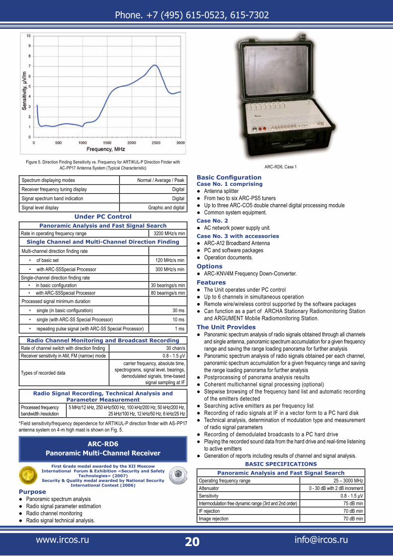
*Field sensitivity/frequency dependence for ARTIKUL-P direction finder with AS-PP17 antenna system on 4-m high mast is shown on Fig. 5.
ARC-RD6Panoramic Multi-Channel Receiver
First Grade medal awarded by the XII Moscow International Forum & Exhibition «Security and Safety
Technologies» (2007) Security & Quality medal awarded by National Security
International Contest (2006)
Purpose Panoramic spectrum analysis ●Radio signal parameter estimation ●Radio channel monitoring ●Radio signal technical analysis. ●
Basic ConfigurationCase No. 1 comprising
Antenna splitter ●From two to six ARC-PS5 tuners ●Up to three ARC-CO5 double channel digital processing module ●Common system equipment. ●
Case No. 2AC network power supply unit. ●
Case No. 3 with accessoriesARC-A12 Broadband Antenna ●PC and software packages ●Operation documents. ●
OptionsARC-KNV4M Frequency Down-Converter ● .
FeaturesThe Unit operates under PC control ●Up to 6 channels in simultaneous operation ●Remote wire/wireless control supported by the software packages ●Can function as a part of ARCHA Stationary Radiomonitoring Station ●and ARGUMENT Mobile Radiomonitoring Station.
The Unit ProvidesPanoramic spectrum analysis of radio signals obtained through all channels ●and single antenna, panoramic spectrum accumulation for a given frequency range and saving the range loading panorama for further analysis Panoramic spectrum analysis of radio signals obtained per each channel, ●panoramic spectrum accumulation for a given frequency range and saving the range loading panorama for further analysis Postprocessing of panorama analysis results ●Coherent multichannel signal processing (optional) ●Stepwise browsing of the frequency band list and automatic recording ●of the emitters detected Searching active emitters as per frequency list ●Recording of radio signals at IF in a vector form to a PC hard disk ●Technical analysis, determination of modulation type and measurement ●of radio signal parameters Recording of demodulated broadcasts to a PC hard drive ●Playing the recorded sound data from the hard drive and real-time listening ●to active emittersGeneration of reports including results of channel and signal analysis. ●
BASIC SPECIFICATIONS
Panoramic Analysis and Fast Signal SearchOperating frequency range 25 – 3000 MHzAttenuator 0 - 30 dB with 2 dB incrementSensitivity 0.8 - 1.5 μVIntermodulation free dynamic range (3rd and 2nd order) 75 dB minIF rejection 70 dB minImage rejection 70 dB min
Figure 5. Direction Finding Sensitivity vs. Frequency for ARTIKUL-P Direction Finder with AC-PP17 Antenna System (Typical Characteristic) ARC-RD6, Case 1

Phone. +7 (495) 615-0523, 615-7302
www.ircos.ru [email protected]
Panoramic Analysis and Fast Signal SearchSimultaneous spectrum analysis band per channel 5 MHzRate per channel 1500 MHz/sPower supply
AC network power supply• 90 - 250 VVehicle power supply• 10 - 15 VInternal battery supply• 12 V
Radio channel monitoring and broadcast recordingNumber of channels under control 2 - 6No. of frequencies in task 255No. of ranges per task 255Receiver tuning resolution 1 Hz,Demodulation types AM, FM, SSB, frequency telegraphy
Radio signal recording & technical analysisProcessed frequency bandwidth/resolution
5 MHz/12 kHz, 250 kHz/1000 Hz, 100 kHz/500 Hz,50 kHz/200 Hz, 25 kHz/100 Hz, 12 kHz/50 Hz, 6 kHz/25 Hz
Receiver is designed based on ARC-PS5 Tuner.
ARC-D11Two-Channel Panoramic Radio Receiver
Processing techniques and equipment are protected by the RF patents.
First Grade medal awarded by the XII Moscow International Forum & Exhibition «Security and Safety
Technologies» (2007) Security & Quality medal awarded by National Security
International Contest (2006)
The equipment has got a certificate of compliance No. 03.009.0403 and registered in instruments facultative registration system
PurposeOutdoor/indoor radio monitoring applications including: ●
Panoramic spectrum analysis• Radio signal parameter measurement• Wire network monitoring• Radio signal technical analysis• Direction finding (with additional equipment).•
Basic ConfigurationCase No. 1 comprising
Antenna switches ●Two ARC-PS5 tuners ●ARC-CO5 double channel digital processing module ●Wire network monitoring unit ●AC and vehicle on-board power unit with charger and battery ●Common system equipment. ●
Case No. 2 with accessoriesBroadband antenna set ●ARC-ASP2 active network probe ●ARC-PSP2 passive network probe ●PC and software packages ●Operation documents ● .
OptionsARC-KNV3 or ARC-KNV4M Frequency Down-Converter ●AS-PP4 or AS-PP17 foldable mast-mounted antenna system ●AS-MP07or AS-MP17 vehicle-mounted radome antenna system ●ARC-A12 Broadband Antenna ●Directional antenna set and handle provided for amplitude direction finding in ●hard-to-reach areasARC-KN1 Navigation Equipment (digital maps to be purchased by the ●Customer and installed following the guidelines provided by the company).
FeaturesSystem has two coherently linked channels of receipt and processing ●PC-controlled operation ●Wire/wireless control and data exchange supported by the software packages. ●
Basic FunctionsReal-time two-channel synchronous radio monitoring ●Two-channel synchronous or single-channel search, accumulation and ●maintenance of signal source database and processing of results
Detection of noise-like signals ●Saving IF radio signals to the PC hard disk ●Technical analysis, determination of modulation type and measurement of ●radio signal parametersWire network monitoring. ●
Additional FunctionsSingle and multi-channel direction finding with an additional antenna ●system, signal level estimation with arbitrary spectrum widthRemote indoor radio monitoring. ●
BASIC SPECIFICATIONSOperating frequency range (basic configuration) 9 kHz – 3000 MHzFrequency range, complete configuration (for one channel only) 9 kHz - 18 GHzInput attenuator 0 -30 dB with 2 dB incrementMaximum allowable input voltage 23 dBmNoise figure within 25 – 465 MHz range 12 dB max.Noise figure within 465 – 3000 MHz range 12 - 14 dB
When Operated with Internal Reference GeneratorRelative error of frequency tuning ±5x10⁻⁷Temperature fluctuations at minus -20°C to +55°C ±5x10⁻⁷Frequency fluctuations per day ±5x10⁻⁷
Selectivity and Harmonic DistortionsIF rejection, min. 70 dBImage rejection, min. 70 dBIntermodulation free dynamic range (3rd and 2nd order), min 75 dBInput IP3, without attenuators, min. 0 dBmInput IP3 with 30 dB attenuator, min. 30 dBmTransfer factor irregularity at operating frequencies of the basic configuration, max. ±3 dB
IF SignalIF analogue signal frequency 10.7 MHz, 41.6 MHzBandpass before 10.7 MHz IF output ±1 dB variation 2 MHzBandpass before 41.6 MHz IF output ±1.5 dB variation 5 MHz
Panoramic Analysis and Fast Signal SearchPanoramic spectrum analysis rate, min. 3200 MHz/sInput sensitivity, max. 0.8 - 1.5 μV
ARC-D11

Phone. +7 (495) 615-0523, 615-7302
www.ircos.ru [email protected]
Single Channel and Multi-Channel Direction FindingDirection finding method Correlative interferometerOperating azimuth 0° - 360°Operating frequency range
With AS-PP07, AS-MP07 Antenna Systems• 25 – 1000 MHzWith AS-PP17, AS-MP17 Antenna Systems• 25 – 3000 MHz
Multi-channel direction finding rate, min 120 MHz/sProcessed signal spectrum width ArbitraryInstrument accuracy (RMS):
With AS-MP07, AS-MP17 Antenna Systems• 2,5°With AS-PP07, AS-PP17 Antenna Systems• 1,5°
Indoor radio monitoring (from 9 kHz to 3000 MHz)
Antenna switch coupling attenuation, min. 40 dBSystem total sensitivity (wattage of a transmitter in an 8 x 8m room with 0.99 probability detection) 100 μW
Wire network monitoringSignal detection level:
from 0.05 kHz to 10 kHz• 1 mW maxfrom 10 kHz to 1 MHz• 100 μW maxfrom 1 MHz to 30 MHz• 10 μW max
Input impedance of a remote wire network transmitter 1 MOhm min.Wire network voltage up to 400 V
Radio signal recording & technical analysisProcessed frequency bandwidth/resolution
5 MHz/12 kHz, 250 kHz/500 Hz, 100 kHz/200 Hz, 50 kHz/200 Hz, 25 kHz/100 Hz, 12 kHz/50 Hz, 6 kHz/25 Hz
Demodulated signal recordingNo. of frequencies in task 255Demodulator frequency band 250 kHz, 100 kHz, 50 kHz, 12 kHz, 6 kHz, 3 kHzReceiver sensitivity in AM, FM (narrow) mode 0.8 - 1.5 μV
Receiver tuning resolution 1 Hz,Demodulation types AM, FM, SSB, continuous emission, frequency telegraphy
Operating Parameters Operating temperature range -20°C … +55°CAC network power supply 90 - 250 VVehicle power supply 10 - 15 VInternal battery supply 12 VPower consumption, max. 40 WCase dimensions, mm 486 x 398 x 194 mmBasic set weight, max 11 kg
Receiver is designed based on ARC-PS5 Tuner.
ARC-D1TM-8Portable Multi-Functional Radio Monitoring
System
Processing techniques and equipment are protected by the RF patents
PurposeOutdoor/indoor radio monitoring applications including: ●
Panoramic spectrum analysis• Radio signal parameter estimation• Radio signal technical analysis. •
Basic Configuration Case No. 1 comprising
Antenna switch modulle ●ARC-PS5 Controlled Tuner module ●ARC-CO5 Digital Processing Module ●ARC-KNV3 Frequency Down-Converter module ●IF output module for peripheral devices ●Wire network monitoring unit ●AC and vehicle on-board power unit with charger and battery. ●
Case No. 2 with accessoriesBroadband antenna set: ●
ARC-A2M Broadband Antenna• ARC-A12 Broadband Antenna• ARC-A14K Broadband Antenna (3 – 8 GHz)•
PC and software packages ●ARC-ASP2 active network probe ●ARC-PSP2 passive network probe ●Operation documents ●Connecting cables. ●
Case No. 3:ARC-MA2 Magnetic Antenna. ●
OptionsDirectional antenna set and handle provided for amplitude direction finding ●in hard-to-reach areasRemote-controlled ARC-KNV4M Frequency Down-Converter. ●
FeaturesIF analog output with central frequency (10.7 / 41.6 / 70 MHz) software ●switching and increase output level (up to 0 dBm)PC-controlled operation ●All applications are supported without additional hardware - you need just ●to change the software packagesWire/wireless control and data exchange supported by the software packages ● .
The system providesReal-time radio monitoring ●Search for the radio signals, maintenance of signal source database and ●processing of resultsIndoor emission scanning ●Continuous recording radio signals within the band up to 2 MHz to PC hard disk ●Recording radio signal fragments within the band up to 5 MHz ●Technical analysis, determination of modulation type and evaluation of ●radio signal parametersWire network monitoring. ●
BASIC SPECIFICATIONS
Panoramic Analysis and Fast Signal SearchOperating frequency range of the basic set 9 kHz - 8 GHzFrequency range, complete configuration 9 kHz - 18 GHzIntermodulation free dynamic range (3rd and 2nd order) 75 dB minRate in operating range 1600 MHz/s min
Radio Signal Demodulation and Recording, Technical Analysis
Processed frequency bandwidth/resolution
5 MHz/12 kHz, 250 kHz/500 Hz, 100 kHz/200 Hz, 50 kHz/200 Hz, 25 kHz/100 Hz, 12 kHz/50 Hz, 6 kHz/25 Hz
Demodulator frequency band 250, 100, 50, 25, 12, 6, 3 kHzReceiver tuning resolution 1 Hz,Demodulation types AM, FM, SSB, frequency telegraphy
ARC-D1TM-8

Phone. +7 (495) 615-0523, 615-7302
www.ircos.ru [email protected]
ARTIKUL-H1Manpack Wideband Automatic Direction Finder
PurposeRadio monitoring and direction finding applications (on the move and at ●stops) including
Direction finding • Radio transmitters localization• Panoramic spectrum analysis• Field strength estimation• Radio signal parameter estimation• Radio signal technical analysis• Radio channel monitoring.•
ConfigurationPanoramic radio receiver based on ARC-PS5 and ARC-CO5 modules in ●compact casePDA with software package ●Set of cables ●Antenna system for automatic direction finding ●Battery set, AC power supply, vehicle-based power supply and charger ●Equipment backpack for operation on the move ●Operation documents. ●
OptionsRugged PDA ●Broadband radio-monitoring antennas ●Handheld ARC-KNV4М Frequency Down-Converter (3 - 18 GHz) ●Directional antenna set and handle provided for amplitude direction finding ●in hard-to-reach areasAntenna mounting set for vehicles ●PC and software packages for automated radio monitoring, technical ●analysis and postprocessing.
FeaturesIn the backpack version, the unit is controlled via a PDA. ●In stationary version and when used on a vehicle, the unit is controlled via a PC. ●
Direction Finder ProvidesUnder PDA-control
Automated radio monitoring ●Automatic direction finding ●Est imat ion of e lec t romagnet ic f ie ld st rength and radio s ignal ●parametersDemodulated signal listening. ●
Under PC controlFull-scale automated radio monitoring including panoramic and technical ●analysis in real-time and in postprocessing mode Single-channel and multi-channel automatic direction finding ●Est imat ion of e lec t romagnet ic f ie ld st rength and radio s ignal ●parameters Automated radio channel monitoring ●Emitter localization and showing the results in electronic map ●Saving demodulated signals, service parameters and IF radio signals ●in a vector form to a PC hard drive Playback of demodulated broadcasts and service parameters. ●
Note: To learn more about design and operating features of ARTIKUL-N1 direction finder as well as to try it in real electromagnetic conditions under a PDA or PC control is possible in the company office.
BASIC SPECIFICATIONS
General
Operating frequency range, receiving mode 25 – 3000 MHz
Intermodulation free dynamic range (3rd and 2nd order) 75 dB
Receiver sensitivity 0.8 - 1.5 μV
Receiver tuning resolution 1 Hz,
Operating temperature range -20°C … +55°C
Operating set weight (operation when caring by operator) 13 kg
Internal battery supply Yes
Vehicle power supply 10 - 32 V
AC network power supply 90 - 250 V
Continuous battery run-time for the basic configuration, min. 4 hours
UNDER PDA-CONTROL
Panoramic analysis, frequency saving, signal recording
Frequency range saving to PDA memory min. 2 hours
Registered parameters Recording based on amplitude/frequency/time coordinates
Velocity 50 MHz/s
Spectrum displaying modes Normal / Average / Peak
Receiver frequency tuning display Digital
Signal spectrum band indication Digital
Signal level display Graphic and digital
Handheld Radio Monitoring and Direction Finding Equipment
Handheld equipment is purposed for operation when operator is moving. They can be placed on the body (in hands) of the operator. These devices can also be used for automated radio monitoring at temporary or stationary posts. As for the way of applications these units can be classified as universal ones. They can be used for monitoring radio signal source in hard-to-reach areas or in the areas where automatic radio monitoring must be concealed, for example, when state supervision agencies control communications in the streets of the cities or industry centers. Due to significant limitations for consumptions, weight and dimensions the specifications of the equipment are selected based on compromise of possible parameters and power consumed, i.e. operation time with one set of power units without replacement.This section presents handheld equipment produced by IRCOS.
Figure 6. Field sensitivity vs. frequency for Artikul-H1 Direction Finder within frequency range fro 25 to 3000 MHz. (Typical Characteristic)

Phone. +7 (495) 615-0523, 615-7302
www.ircos.ru [email protected]
Automatic direction finding
Direction finding method Correlative interferometer
Operating frequency range 25 – 3000 MHz
within 100 - 3000 MHz range 1 - 4 μV/m
within 25 - 100 MHz range 3 - 25 μV/m
Instrument accuracy (RMS) 2° - 5°
UNDER PC CONTROL
Panoramic analysis and frequency saving
Frequency range load recording time 24 hours
Registered parameters Recording based on amplitude/frequency/time coordinates
Rate (with 6 kHz discreteness) 1600 MHz/s
Single-channel and multi-channel automatic direction finding
Direction finding method Correlative interferometer
Operating frequency range 25 – 3000 MHz
within 100 - 3000 MHz range 1 - 4 μV/m
within 25 - 100 MHz range 3 - 25 μV/m
Instrument accuracy (RMS) 2° - 5°
Radio channel monitoring and broadcast recording
Channel switch rate 30 channels/s
Continuous saving time 24 hours
Types of recorded data signal, time, frequency
Technical analysis, radio signal recording and postprocessing
Frequency band width for IF signal fragment recording
2 MHz, 250 kHz, 100 kHz, 50 kHz, 25 kHz, 12 kHz, 6 kHz
* Instrument accuracy (RMS) of direction f inding in 100-3000 MHz pertains to the cases when the DF antenna system is mounted on a roof of a road vehicle or borne by operator When the antenna system is mounted on other vehicles (helicopter, delta plane, aircraft or air drone), the direction finding accuracy/error is neither guaranteed nor specified, depends on the influence from the carrier and requires additional checks.In the range of 25 - 100 MHz, the RMS is not specified.Figure 6 shows typical sensitivity vs. frequency dependency of ARTIKUL-H1 Direction Finder.
ARC-RP3, ARC-RP3MHandheld Direction Finders
Security & Quality medal awarded by National Security International Contest (2004)
First Grade medal awarded by the XX Moscow International Forum & Exhibition «Security and Safety
Technologies» (2005)
PurposeOutdoor/indoor radio monitoring applications including: ●
Direction finding • Radio transmitters localization• Panoramic spectrum analysis• Field strength estimation• Radio signal parameter estimation• Radio signal technical analysis• Radio channel monitoring.•
ConfigurationPanoramic radio receiver in a compact case ●PDA with software package ●
Set of cables ●Antenna system for manual direction finding ●
Handle with a combined LED indicator• ARC-A3-KV Antenna Module (0.3-36 MHz) – for ARC-RP3 only• ARC-A3-0 Antenna Module (25 - 200 MHz)• ARC-A3-1 Antenna Module (90 - 450 MHz)• ARC-A3-2 Antenna Module (400 - 850 MHz)• ARC-A3-3 Antenna Module (800 - 3000 MHz)•
Battery set, AC power supply, vehicle-based power supply and charger ●Equipment carry bag for operation when moving ●Backpack for equipment ●Operation documents. ●
OptionsARC-A3-1 Active Antenna Module ●Antenna system for the range from 3 to 8 GHz comprising built-in ●ARC-KNV3 Frequency Down Converter and directional antenna module (for ARC-RP3M only)Handheld ARC-KNV4М (3 - 18 GHz) Frequency Down-Converter for ●direction finding. Used with integral directional antenna system to be mounted instead of the handle.Broadband radio-monitoring antennas ●PC and software packages for automatic radio monitoring, technical ●analysis and postprocessingAdditional batteries (for ARC-RP3M). ●
FeaturesOn the move, the unit is controlled via a PDA. ●When stationary, the unit is controlled via a PC ●The system also provides for direction finding in concealed mode. Details are ●available upon request.
The system providesUnder PDA-control
Automated radio monitoring ●Panoramic analysis of radio signal spectrum with visual displaying ●of radio signals within specif ied frequency rangeDisplaying radio signal spectrum about specif ied frequency ●Manual direction f inding ●Est imat ion of e lec t romagnet ic f ie ld st rength and radio s ignal ●parameters .
Under PC controlFull -scale automated radio monitor ing including panoramic and ●technical analysis in real-t ime and in postprocessing modeEst imat ion of e lec t romagnet ic f ie ld st rength and radio s ignal ●parametersAutomated radio channel monitoring ●Saving demodulated signals, service parameters and IF radio signals ●in a vector form to a PC hard drivePlayback of demodulated broadcasts and service parameters. ●
BASIC SPECIFICATIONS
General
Operating frequency range, receiving mode
ARC-RP3 basic set• 0.3 – 3000 MHz
ARC-RP3M basic set• 25 – 3000 MHz
ARC-RP3 with ARC-KNV4M • 0.3 – 18,000 MHz
ARC-RP3 and ARC-RP3M Handheld Direction Finder Delivery Set

Phone. +7 (495) 615-0523, 615-7302
www.ircos.ru [email protected]
General
ARC-RP3M with ARC-KNV3• 25 – 8,000 MHz
ARC-RP3M with ARC-KNV4M • 25 – 18,000 MHz
Intermodulation free dynamic range (3rd and 2nd order) 75 dB min
Receiver tuning resolution 1 Hz,
Operating temperature range -20°C … +55°C
Internal battery supply Yes
Vehicle power supply 10 - 32 V
AC network power supply 90 - 250 V
Continuous battery run-time for the ARC-RP3 basic configuration min. 6 hours
Continuous battery run-time for the ARC-RP3 basic configuration, depending on battery capacity 2 – 8 hours
Operating set weight (in carry bag):
ARC-RP3 • 8 kg
ARC-RP3M with built-in battery provided for 2 hour • continuous operation 3.5 kg
Operating set weight (in backpack):
ARC-RP3 • 13 kg
ARC-RP3M • 8 kg
Dimensions of ARC-RP3 (in shoulder bag) 400 x 330 x 180 mm
Dimensions of ARC-RP3 (in backpack) 510 x 500 x 250 mm
Dimensions of ARC-RP3M (receiver) 110 x 50 x 220 mm
Dimensions of ARC-RP3M (in shoulder bag) 400 x 330 x 180 mm
UNDER PDA-CONTROL
Direction finding
Direction finding method Amplitude
Sensitivity in direction finding mode (basic configuration) 5 - 25 μV/m
Signal level evaluation limits (with attenuators) -10 - 110 dB
Direction finding instrument accuracy (basic configuration) 7° – 15°
Panoramic analysis, frequency saving, signal recording
Frequency range saving to PDA memory min. 2 hours
Registered parameters Recording based on amplitude/frequency/time coordinates
Velocity 50 MHz/s
Displayed frequency band up to 20 MHz
Spectrum displaying modes Normal / Average / Peak
Receiver frequency tuning display Digital
Signal spectrum band indication Digital
Signal level display Graphic and digital
Radio channel monitoring and broadcast recording
Frequency band width for signal fragment recording 50 kHz, 25kHz, 12 kHz, 6 kHz
Types of recorded data radio signal, time, frequency
UNDER PC CONTROL
Panoramic analysis and frequency saving
Frequency range load recording time 24 hours
Registered parameters Recording based on amplitude/frequency/time coordinates
Rate (with 3 kHz discreteness) 700 MHz/s
Radio channel monitoring and broadcast recording
Channel switch rate 30 channels/s
Receiver sensitivity 0.8 - 1.5 μV
Continuous saving time 24 hours
Types of recorded data signal, time, frequency
Technical analysis, radio signal recording and postprocessing
Frequency band width for IF signal fragment recording
2 MHz 250 kHz, 100 kHz, 50 kHz, 25 kHz, 12 kHz, 6 kHz
Field sensitivity vs. frequency for ARC-RP3 and ARC-RP3M in direction finding mode is shown on the Figure 7
ARC-RP3 and ARC-RP3M Handheld Direction Finder in Operation
Figure 7. Field Sensitivity vs. Frequency for ARC-RP3 in Direction Finding Mode (Typical Characteristic)
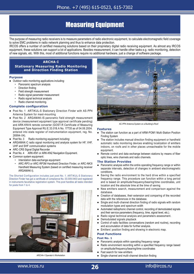
Phone. +7 (495) 615-0523, 615-7302
www.ircos.ru [email protected]
ARCHA-IStationary Measuring Radio Monitoring
and Direction Finding Station
PurposeOutdoor radio monitoring applications including: ●
Panoramic spectrum analysis • Direction finding • Field strength measurement • Radio signal parameter measurement • Radio signal technical analysis • Radio channel monitoring.•
Complete configurationPost No. 1 ARTIKUL-S Stationary Direction Finder with AS-PP4 ●Antenna System for mast-mounting Post No. 2 ARGAMAK-IS panoramic f ield strength measurement ●device (measurement equipment type approval certif icate pending) and ARK-KNV4 remote converter (GOST-R Certificate of Measuring Equipment Type Approval RU.E.33.018.A No. 17735 as of 04.06.2004. entered into state register of instrumentation equipment, reg. No. 26994-04). Post No. 3 Radio monitoring equipment including: ●ARGAMAK-C radio signal monitoring and analysis system for HF, VHF, ●UHF and SHF communication systems ARC-CRS Signal Digital Recorder ●Post No. 4 ARK-KN1 or ARK-KN2 Navigation Equipment. ●Common system equipment: ●
Interstation data exchange equipment • ARC-RP3 or ARC-RP3M Handheld Direction Finder, or ARC-NK3I • Handheld Measuring System (based on certified measuring receiver ARGAMAK-I).
The Shor ted Conf igurat ion includes just post No. 1. ARTIKUL-S Stat ionary Direction Finder has got a certificate of compliance No. 03.009.0403 and registered in instruments facultative registration system. This post handles all tasks intended for posts from 1 to 4.
FeaturesThe station can function as a part of ARM-POM1 Multi-Station Position ●Finding System The station includes manual direction finding equipment or handheld ●automatic radio monitoring devices enabling localization of emitters indoors, on roofs and in other places unreacheable for the mobile equipment. Remote control and data exchange between stations by means of fiber ●optic lines, wire channels and radio channels.
The Station ProvidesPanoramic analysis within the entire operating frequency range or within ●separate intervals, detection of changes in ambient electromagnetic conditions. Saving the radio environment to the hard drive within a specif ied ●frequency range. This procedure can function within a long period and is based on amplitude/frequency/bearing/time coordinates, unit location and the absolute time at the time of saving. New emit ters search, measurement and comparison against the ●database. Creation of databases, their extension and comparing of the recorded ●data with the references in the database. Single and multi-channel direction finding of radio signals with random ●modulation types and spectrum width Automated radiophonic channel control, recording of demodulated signals ●and their service parameters (frequency, time, signal level, etc.). Radio signal technical analysis and parameters assessment. ●Demodulated signals playback ●Control of radio facilities conversations (random and routine), recording ●and accumulation of data for further analysis. Emitters’ position finding and showing in electronic map ● .
Post FunctionsPost No. 1
Panoramic analysis within operating frequency range ●Radio environment recording within a specified frequency range based ●on amplitude/frequency/bearing/time coordinates Fast search for new emitters ●Single-channel and multi-channel direction finding ●
Measuring Equipment
The purpose of measuring radio receivers is to measure parameters of radio electronic equipment, to calculate electromagnetic field coverage to solve EMC problems in radio network planning and thus to enhance data protection.IRCOS offers a number of certified measuring solutions based on their proprietary digital radio receiving equipment. As almost any IRCOS equipment, these solutions can support a lot of applications. Besides measurement, it can handle other tasks e.g. radio monitoring, detection of new signals, etc. With this, most of additional functions require no additional hardware, just a change of software package.
ARCHA-I Operator’s Workstation
AC-PP4 Antenna System on a Building’s Roof
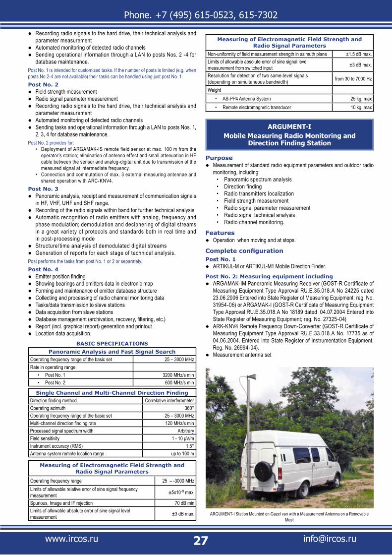
Phone. +7 (495) 615-0523, 615-7302
www.ircos.ru [email protected]
Recording radio signals to the hard drive, their technical analysis and ●parameter measurement Automated monitoring of detected radio channels ●Sending operational information through a LAN to posts Nos. 2 -4 for ●database maintenance.
Post No. 1 is intended for customized tasks. If the number of posts is limited (e.g. when posts No.2-4 are not available) their tasks can be handled using just post No. 1.Post No. 2
Field strength measurement ●Radio signal parameter measurement ●Recording radio signals to the hard drive, their technical analysis and ●parameter measurement Automated monitoring of detected radio channels ●Sending tasks and operational information through a LAN to posts Nos. 1, ●2, 3, 4 for database maintenance.
Post No. 2 provides for:Deployment of ARGAMAK-IS remote field sensor at max. 100 m from the • operator’s station; elimination of antenna effect and small attenuation in HF cable between the sensor and analog-digital unit due to transmission of the measured signal at intermediate frequency.Connection and commutation of max. 3 external measuring antennae and • shared operation with ARC-KNV4.
Post No. 3Panoramic analysis, receipt and measurement of communication signals ●in HF, VHF, UHF and SHF range.Recording of the radio signals within band for further technical analysis ●Automatic recognition of radio emitters with analog, frequency and ●phase modulation; demodulation and deciphering of digital streams in a great variety of protocols and standards both in real time and in post-processing modeStructure/time analysis of demodulated digital streams ●Generation of reports for each stage of technical analysis. ●
Post performs the tasks from post No. 1 or 2 or separately.Post No. 4
Emitter position finding ●Showing bearings and emitters data in electronic map ●Forming and maintenance of emitter database structure ●Collecting and processing of radio channel monitoring data ●Tasks/data transmission to slave stations ●Data acquisition from slave stations ●Database management (archivation, recovery, filtering, etc.) ●Report (incl. graphical report) generation and printout ●Location data acquisition. ●
BASIC SPECIFICATIONSPanoramic Analysis and Fast Signal Search
Operating frequency range of the basic set 25 – 3000 MHzRate in operating range:
Post No. 1• 3200 MHz/s min Post No. 2• 600 MHz/s min
Single Channel and Multi-Channel Direction FindingDirection finding method Correlative interferometerOperating azimuth 360°Operating frequency range of the basic set 25 – 3000 MHzMulti-channel direction finding rate 120 MHz/s min Processed signal spectrum width ArbitraryField sensitivity 1 - 10 μV/mInstrument accuracy (RMS) 1.5°Antenna system remote location range up to 100 m
Measuring of Electromagnetic Field Strength and Radio Signal Parameters
Operating frequency range 25 – -3000 MHzLimits of allowable relative error of sine signal frequency measurement ±5x10⁻⁹ max.
Spurious, Image and IF rejection 70 dB minLimits of allowable absolute error of sine signal level measurement ±3 dB max.
Measuring of Electromagnetic Field Strength and Radio Signal Parameters
Non-uniformity of field measurement strength in azimuth plane ±1.5 dB max.Limits of allowable absolute error of sine signal level measurement from switched input ±3 dB max.
Resolution for detection of two same-level signals (depending on simultaneous bandwidth) from 30 to 7000 Hz
WeightAS-PP4 Antenna System• 25 kg, maxRemote electromagnetic transducer• 10 kg, max
ARGUMENT-IMobile Measuring Radio Monitoring and
Direction Finding Station
PurposeMeasurement of standard radio equipment parameters and outdoor radio ●monitoring, including:
Panoramic spectrum analysis• Direction finding • Radio transmitters localization• Field strength measurement• Radio signal parameter measurement• Radio signal technical analysis• Radio channel monitoring.•
FeaturesOperation when moving and at stops. ●
Complete configurationPost No. 1
ARTIKUL-M or ARTIKUL-M1 Mobile Direction Finder. ●Post No. 2: Measuring equipment including
ARGAMAK-IM Panoramic Measuring Receiver (GOST-R Certificate of ●Measuring Equipment Type Approval RU.E.35.018.A No 24225 dated 23.06.2006 Entered into State Register of Measuring Equipment; reg. No. 31954-06) or ARGAMAK-I (GOST-R Certificate of Measuring Equipment Type Approval RU.E.35.018.A No 18189 dated 04.07.2004 Entered into State Register of Measuring Equipment; reg. No. 27325-04)ARK-KNV4 Remote Frequency Down-Converter (GOST-R Certificate of ●Measuring Equipment Type Approval RU.E.33.018.A No. 17735 as of 04.06.2004. Entered into State Register of Instrumentation Equipment, Reg. No. 26994-04).Measurement antenna set ●
ARGUMENT-I Station Mounted on Gazel van with a Measurement Antenna on a Removable Mast
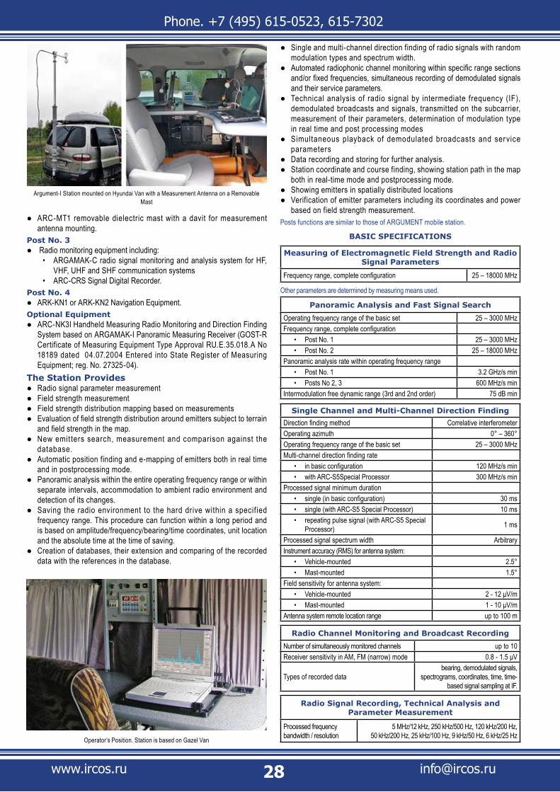
Phone. +7 (495) 615-0523, 615-7302
www.ircos.ru [email protected]
ARC-MT1 removable dielectric mast with a davit for measurement ●antenna mounting.
Post No. 3 Radio monitoring equipment including: ●
ARGAMAK-C radio signal monitoring and analysis system for HF, • VHF, UHF and SHF communication systems ARC-CRS Signal Digital Recorder.•
Post No. 4ARK-KN1 or ARK-KN2 Navigation Equipment. ●
Optional EquipmentARC-NK3I Handheld Measuring Radio Monitoring and Direction Finding ●System based on ARGAMAK-I Panoramic Measuring Receiver (GOST-R Certificate of Measuring Equipment Type Approval RU.E.35.018.A No 18189 dated 04.07.2004 Entered into State Register of Measuring Equipment; reg. No. 27325-04).
The Station ProvidesRadio signal parameter measurement ●Field strength measurement ●Field strength distribution mapping based on measurements ●Evaluation of field strength distribution around emitters subject to terrain ●and field strength in the map. New emit ters search, measurement and comparison against the ●database. Automatic position finding and e-mapping of emitters both in real time ●and in postprocessing mode. Panoramic analysis within the entire operating frequency range or within ●separate intervals, accommodation to ambient radio environment and detection of its changes. Saving the radio environment to the hard drive within a specif ied ●frequency range. This procedure can function within a long period and is based on amplitude/frequency/bearing/time coordinates, unit location and the absolute time at the time of saving. Creation of databases, their extension and comparing of the recorded ●data with the references in the database.
Single and multi-channel direction finding of radio signals with random ●modulation types and spectrum width. Automated radiophonic channel monitoring within specific range sections ●and/or fixed frequencies, simultaneous recording of demodulated signals and their service parameters. Technical analysis of radio signal by intermediate frequency (IF), ●demodulated broadcasts and signals, transmitted on the subcarrier, measurement of their parameters, determination of modulation type in real time and post processing modes Simultaneous playback of demodulated broadcasts and service ●parameters Data recording and storing for further analysis. ●Station coordinate and course finding, showing station path in the map ●both in real-time mode and postprocessing mode. Showing emitters in spatially distributed locations ●Verification of emitter parameters including its coordinates and power ●based on field strength measurement.
Posts functions are similar to those of ARGUMENT mobile station.
BASIC SPECIFICATIONS
Measuring of Electromagnetic Field Strength and Radio Signal Parameters
Frequency range, complete configuration 25 – 18000 MHz
Other parameters are determined by measuring means used.
Panoramic Analysis and Fast Signal Search
Operating frequency range of the basic set 25 – 3000 MHzFrequency range, complete configuration
Post No. 1• 25 – 3000 MHzPost No. 2• 25 – 18000 MHz
Panoramic analysis rate within operating frequency rangePost No. 1• 3.2 GHz/s min Posts No 2, 3• 600 MHz/s min
Intermodulation free dynamic range (3rd and 2nd order) 75 dB min
Single Channel and Multi-Channel Direction FindingDirection finding method Correlative interferometerOperating azimuth 0° – 360°Operating frequency range of the basic set 25 – 3000 MHzMulti-channel direction finding rate
in basic configuration• 120 MHz/s min with ARC-S5Special Processor• 300 MHz/s min
Processed signal minimum durationsingle (in basic configuration)• 30 mssingle (with ARC-S5 Special Processor)• 10 msrepeating pulse signal (with ARC-S5 Special • Processor) 1 ms
Processed signal spectrum width ArbitraryInstrument accuracy (RMS) for antenna system:
Vehicle-mounted• 2.5°Mast-mounted• 1.5°
Field sensitivity for antenna system:Vehicle-mounted• 2 - 12 μV/mMast-mounted• 1 - 10 μV/m
Antenna system remote location range up to 100 m
Radio Channel Monitoring and Broadcast Recording
Number of simultaneously monitored channels up to 10Receiver sensitivity in AM, FM (narrow) mode 0.8 - 1.5 μV
Types of recorded databearing, demodulated signals,
spectrograms, coordinates, time, time-based signal sampling at IF.
Radio Signal Recording, Technical Analysis and Parameter Measurement
Processed frequency bandwidth / resolution
5 MHz/12 kHz, 250 kHz/500 Hz, 120 kHz/200 Hz, 50 kHz/200 Hz, 25 kHz/100 Hz, 9 kHz/50 Hz, 6 kHz/25 HzOperator’s Position. Station is based on Gazel Van
Argument-I Station mounted on Hyundai Van with a Measurement Antenna on a Removable Mast
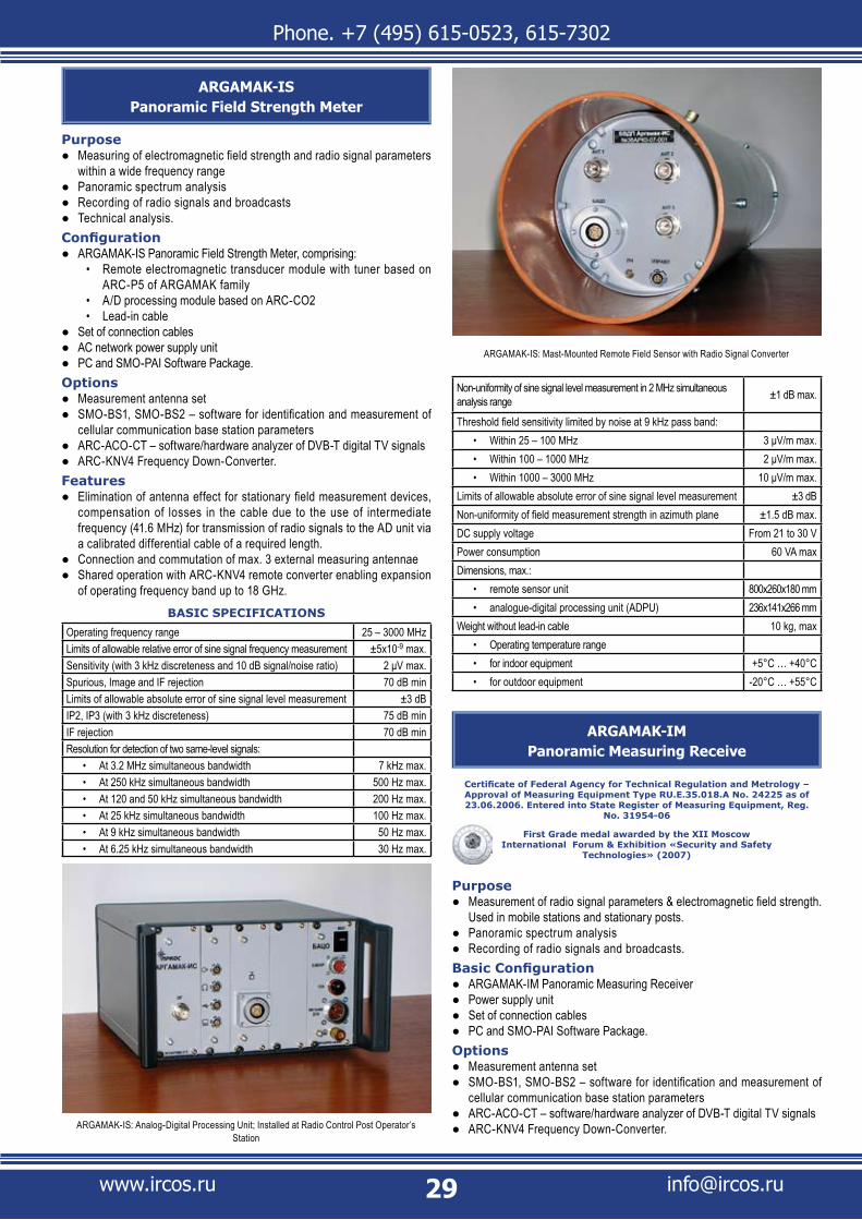
Phone. +7 (495) 615-0523, 615-7302
www.ircos.ru [email protected]
ARGAMAK-ISPanoramic Field Strength Meter
PurposeMeasuring of electromagnetic field strength and radio signal parameters ●within a wide frequency range Panoramic spectrum analysis ●Recording of radio signals and broadcasts ●Technical analysis. ●
ConfigurationARGAMAK-IS Panoramic Field Strength Meter, comprising: ●
Remote electromagnetic transducer module with tuner based on • ARC-P5 of ARGAMAK family A/D processing module based on ARC-CO2• Lead-in cable •
Set of connection cables ●AC network power supply unit ●PC and SMO-PAI Software Package. ●
OptionsMeasurement antenna set ●SMO-BS1, SMO-BS2 – software for identification and measurement of ●cellular communication base station parametersARC-ACO-CT – software/hardware analyzer of DVB-T digital TV signals ●ARC-KNV4 Frequency Down-Converter. ●
FeaturesElimination of antenna effect for stationary field measurement devices, ●compensation of losses in the cable due to the use of intermediate frequency (41.6 MHz) for transmission of radio signals to the AD unit via a calibrated differential cable of a required length.Connection and commutation of max. 3 external measuring antennae ●Shared operation with ARC-KNV4 remote converter enabling expansion ●of operating frequency band up to 18 GHz.
BASIC SPECIFICATIONSOperating frequency range 25 – 3000 MHzLimits of allowable relative error of sine signal frequency measurement ±5x10⁻⁹ max.Sensitivity (with 3 kHz discreteness and 10 dB signal/noise ratio) 2 μV max.Spurious, Image and IF rejection 70 dB minLimits of allowable absolute error of sine signal level measurement ±3 dBIP2, IP3 (with 3 kHz discreteness) 75 dB minIF rejection 70 dB minResolution for detection of two same-level signals:
At 3.2 MHz simultaneous bandwidth• 7 kHz max.At 250 kHz simultaneous bandwidth• 500 Hz max.At 120 and 50 kHz simultaneous bandwidth• 200 Hz max.At 25 kHz simultaneous bandwidth• 100 Hz max.At 9 kHz simultaneous bandwidth• 50 Hz max.At 6.25 kHz simultaneous bandwidth• 30 Hz max.
Non-uniformity of sine signal level measurement in 2 MHz simultaneous analysis range ±1 dB max.
Threshold field sensitivity limited by noise at 9 kHz pass band:Within 25 – 100 MHz• 3 μV/m max.Within 100 – 1000 MHz• 2 μV/m max.Within 1000 – 3000 MHz• 10 μV/m max.
Limits of allowable absolute error of sine signal level measurement ±3 dBNon-uniformity of field measurement strength in azimuth plane ±1.5 dB max.DC supply voltage From 21 to 30 VPower consumption 60 VA maxDimensions, max.:
remote sensor unit• 800x260x180 mmanalogue-digital processing unit (ADPU)• 236x141x266 mm
Weight without lead-in cable 10 kg, maxOperating temperature range• for indoor equipment• +5°C … +40°Cfor outdoor equipment• -20°C … +55°C
ARGAMAK-IMPanoramic Measuring Receive
Certificate of Federal Agency for Technical Regulation and Metrology – Approval of Measuring Equipment Type RU.E.35.018.A No. 24225 as of 23.06.2006. Entered into State Register of Measuring Equipment, Reg.
No. 31954-06
First Grade medal awarded by the XII Moscow International Forum & Exhibition «Security and Safety
Technologies» (2007)
PurposeMeasurement of radio signal parameters & electromagnetic field strength. ●Used in mobile stations and stationary posts. Panoramic spectrum analysis ●Recording of radio signals and broadcasts. ●
Basic ConfigurationARGAMAK-IM Panoramic Measuring Receiver ●Power supply unit ●Set of connection cables ●PC and SMO-PAI Software Package. ●
OptionsMeasurement antenna set ●SMO-BS1, SMO-BS2 – software for identification and measurement of ●cellular communication base station parametersARC-ACO-CT – software/hardware analyzer of DVB-T digital TV signals ●ARC-KNV4 Frequency Down-Converter. ●ARGAMAK-IS: Analog-Digital Processing Unit; Installed at Radio Control Post Operator’s
Station
ARGAMAK-IS: Mast-Mounted Remote Field Sensor with Radio Signal Converter

Phone. +7 (495) 615-0523, 615-7302
www.ircos.ru [email protected]
BASIC SPECIFICATIONS
Operating frequency range 25 – 3000 MHzBandpass flatness for IF output ±1 dB max.IF output pass band 2 MHz minImage rejection 70 dB minIF rejection 70 dB minFrequency tuning discreteness in measurement mode 1 Hz,Intermodulation free dynamic range (3rd and 2nd order) within 3 kHz bandpass 75 dB min
Input signal level dynamic measuring range 103 dB minSensitivity (with 3 kHz bandpass and 10 dB signal/noise ratio) with operating frequency range 1 μV max.
Resolution for detection of two same-level signalsAt 3.2 MHz simultaneous bandwidth• 7 kHz max.At 250 kHz simultaneous bandwidth• 500 Hz max.At 120 kHz simultaneous bandwidth• 200 Hz max.At 50 kHz simultaneous bandwidth• 200 Hz max.At 25 kHz simultaneous bandwidth• 100 Hz max.At 9 kHz simultaneous bandwidth• 50 Hz max.At 6.25 kHz simultaneous bandwidth• 30 Hz max.
Limits of allowable absolute error of sine signal level measurement with calibration ±1.5 dB
Limits of allowable absolute error of sine signal level measurement without calibration ±3 dB
Limits of allowable relative error of sine signal frequency measurement when operation of internal reference generator ±3×10⁻⁹
Power consumption max. 35 WPower supply voltage 9 - 32 VContinuous battery run-time (basic set) min. 4 hoursAmbient air temperature From +5°C - 40°CRelative humidity @ 22°C up to 98 %Barometric Pressure 84 - 107 kPaReceiver dimensions in case 300 x 300 x 200 mmWeight 5 kg, max
ARGAMAK-IPanoramic Measuring Receiver
GOST-R Certificate of Measuring Equipment Type Approval RU.E.35.018.A No. 18189 as of 04.07.2004. Entered into State Register of Measuring
Equipment, Reg. No. 27325-04
First Grade medal awarded by the X Moscow International Forum & Exhibition «Security and Safety Technologies»
(2005)
Security & Quality medal awarded by National Security International Contest (2004)
PurposeMeasurement of radio signal & electromagnetic field strength. Used in a ●handheld measurement systems, mobile stations and stationary posts.Panoramic spectrum analysis ●Recording of radio signals and broadcasts. ●
ConfigurationARGAMAK-I panoramic measuring receiver ●Power supply unit ●PC and SMO-PAI Software Package ●Set of connection cables. ●
OptionsMeasurement antenna set ●SMO-BS1, SMO-BS2 – software for identification and measurement of ●cellular communication base station parametersARC-ACO-CT – software/hardware analyzer of DVB-T digital TV signals ●ARK-KNV4 Remote Frequency Down-Converter (GOST-R Certificate of ●Measuring Equipment Type Approval RU.E.33.018.A No. 17735 as of 04.06.2004).
BASIC SPECIFICATIONS
Operating frequency range 25 – 3000 MHzBandpass flatness for IF output ±1 dB max.IF output pass band 2 MHz minImage rejection 70 dB minIF rejection 70 dB min
ARGAMAK-IM with Opened Battery Compartment
ARGAMAK-IM ARGAMAK-I in a Compact Case

Phone. +7 (495) 615-0523, 615-7302
www.ircos.ru [email protected]
ARC-NK3I Basic Configuration
Frequency tuning discreteness in measurement mode 1 Hz,Intermodulation free dynamic range (3rd and 2nd order) within 3 kHz bandpass 75 dB min
Sensitivity (with 3 kHz bandpass and 10 dB signal/noise ratio) with operating frequency range 1 μV max.
Resolution for detection of two same-level signals:At 2 MHz simultaneous bandwidth• 7 kHz max.At 1 MHz simultaneous bandwidth• 7 kHz max.At 250 kHz simultaneous bandwidth• 500 Hz max.At 120 kHz simultaneous bandwidth• 200 Hz max.At 50 kHz simultaneous bandwidth• 200 Hz max.At 25 kHz simultaneous bandwidth• 100 Hz max.At 9 kHz simultaneous bandwidth• 50 Hz max.At 6 kHz simultaneous bandwidth• 30 Hz max.
Limits of allowable absolute error of sine signal level measurement with calibration ±1.5 dB
Limits of allowable absolute error of sine signal level measurement without calibration ±3 dB
Limits of allowable relative error of sine signal frequency measurement (Fi is measurement frequency) Fi x 2 x 10⁻⁶ Hz
Power consumption max. 35 WPower supply voltage 9 - 32 VAmbient air temperature From +5°C - 40°CRelative humidity @ 22°C up to 80 %Barometric Pressure 84 - 107 kPaReceiver dimensions in case 270 x 240 x 130 mmWeight 5 kg, max
ARC-NK3IPortable Radiomonitoring and Direction Finding
Measuring System
PurposeMeasurement of standard radio equipment parameters and electromagnetic ●field strength; outdoor radio monitoring, including
Panoramic spectrum analysis• Direction finding • Radio transmitters localization• Radio signal technical analysis• Radio channel monitoring.•
Basic ConfigurationARGAMAK-I (ARGAMAK-IM) panoramic measurement receiver (GOST-R ●Certificate of Measuring Equipment Type Approval RU.E.35.018.A No. 18189 dated 04.07.2004, Entered into State Register of Measuring Equipment; reg. No. 27325-04)Antenna system (non-calibrated) including: ●
Handle with a combined LED indicator• ARC-A3-0 Antenna Module (25 - 200 MHz)• ARC-A3-1 Antenna Module (90 - 450 MHz)• ARC-A3-2 Antenna Module (370 - 720 MHz)• ARC-A3-3 Antenna Module (700 MHz - 3 GHz)•
Battery set, AC power supply, vehicle-based power supply and charger ●PDA with measurement software ●Carry bag for equipment for operation when moving ●Backpack for equipment. ●
Options Measurement antenna set ●ARK-KNV4 Remote Frequency Down-Converter (GOST-R Certificate of ●Measuring Equipment Type Approval RU.E.33.018.A No. 17735 as of 04.06.2004. Entered into State Register of Instrumentation Equipment, Reg. No. 26994-04) with built-in directional antenna systemPC and software packages for automated radio monitoring, technical ●analysis and postprocessingSupport stand ●Broadband radio-monitoring antennas. ●
FeaturesIntended for operation when moving ●System control is carried out using a wrist control panel, PDA or PC ●The system also provides for direction f inding in concealed mode. ●Details are available upon request.
The system providesUnder PDA-control
Measurement of radio signal parameters & electromagnetic f ield ●strength (with measurement antennas) and reference to geographic coordinatesSpectrum panoramic analysis, signal band measurement. ●
Under PC controlMeasurement of radio signal parameters & electromagnetic field strength ●(with measurement antennas)Panoramic and technical analysis in real-time and in postprocessing ●modeAutomated radio channel monitoring ●Saving radio signals at IF in a vector form, demodulated broadcasts and ●service parameters to a PC hard diskPlayback of demodulated broadcasts and service parameters. ●
BASIC SPECIFICATIONS
Measuring of Electromagnetic Field Strength and Radio Signal Parameters*
Operating frequency range
Basic Configuration• 25 – 3000 MHz
in complete configuration• 25 – 18000 MHz
*Other parameters of the measurement path are determined by ARGAMAK-I receiver parameters.
ARGAMAK-I for Stationary Systems
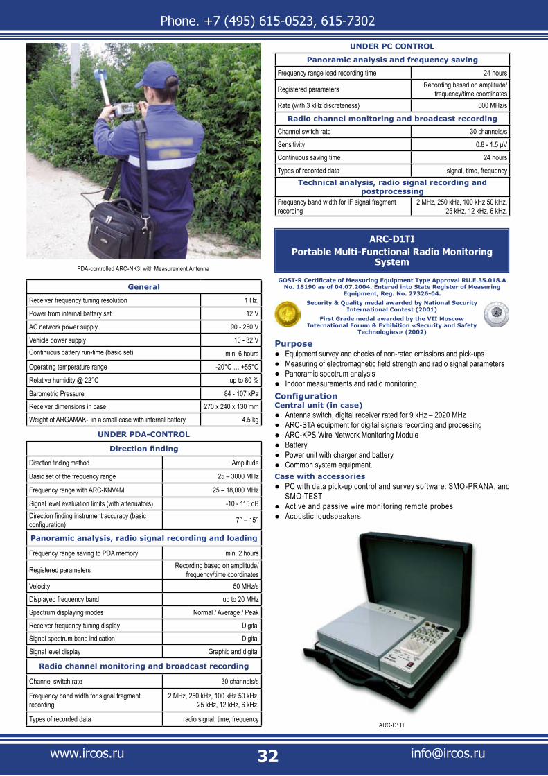
Phone. +7 (495) 615-0523, 615-7302
www.ircos.ru [email protected]
General
Receiver frequency tuning resolution 1 Hz,
Power from internal battery set 12 V
AC network power supply 90 - 250 V
Vehicle power supply 10 - 32 VContinuous battery run-time (basic set) min. 6 hours
Operating temperature range -20°C … +55°C
Relative humidity @ 22°C up to 80 %
Barometric Pressure 84 - 107 kPa
Receiver dimensions in case 270 x 240 x 130 mm
Weight of ARGAMAK-I in a small case with internal battery 4.5 kg
UNDER PDA-CONTROL
Direction finding
Direction finding method Amplitude
Basic set of the frequency range 25 – 3000 MHz
Frequency range with ARC-KNV4M 25 – 18,000 MHz
Signal level evaluation limits (with attenuators) -10 - 110 dBDirection finding instrument accuracy (basic configuration) 7° – 15°
Panoramic analysis, radio signal recording and loading
Frequency range saving to PDA memory min. 2 hours
Registered parameters Recording based on amplitude/frequency/time coordinates
Velocity 50 MHz/s
Displayed frequency band up to 20 MHz
Spectrum displaying modes Normal / Average / Peak
Receiver frequency tuning display Digital
Signal spectrum band indication Digital
Signal level display Graphic and digital
Radio channel monitoring and broadcast recording
Channel switch rate 30 channels/s
Frequency band width for signal fragment recording
2 MHz, 250 kHz, 100 kHz 50 kHz, 25 kHz, 12 kHz, 6 kHz.
Types of recorded data radio signal, time, frequency
UNDER PC CONTROL
Panoramic analysis and frequency saving
Frequency range load recording time 24 hours
Registered parameters Recording based on amplitude/frequency/time coordinates
Rate (with 3 kHz discreteness) 600 MHz/s
Radio channel monitoring and broadcast recording
Channel switch rate 30 channels/s
Sensitivity 0.8 - 1.5 μV
Continuous saving time 24 hours
Types of recorded data signal, time, frequencyTechnical analysis, radio signal recording and
postprocessingFrequency band width for IF signal fragment recording
2 MHz, 250 kHz, 100 kHz 50 kHz, 25 kHz, 12 kHz, 6 kHz.
ARC-D1TIPortable Multi-Functional Radio Monitoring
System
GOST-R Certificate of Measuring Equipment Type Approval RU.E.35.018.A No. 18190 as of 04.07.2004. Entered into State Register of Measuring
Equipment, Reg. No. 27326-04.
Security & Quality medal awarded by National Security International Contest (2001)
First Grade medal awarded by the VII Moscow International Forum & Exhibition «Security and Safety
Technologies» (2002)
PurposeEquipment survey and checks of non-rated emissions and pick-ups ●Measuring of electromagnetic field strength and radio signal parameters ●Panoramic spectrum analysis ●Indoor measurements and radio monitoring. ●
ConfigurationCentral unit (in case)
Antenna switch, digital receiver rated for 9 kHz – 2020 MHz ●ARC-STA equipment for digital signals recording and processing ●ARC-KPS Wire Network Monitoring Module ●Battery ●Power unit with charger and battery ●Common system equipment. ●
Case with accessoriesPC with data pick-up control and survey software: SMO-PRANA, and ●SMO-TESTActive and passive wire monitoring remote probes ●Acoustic loudspeakers ●
PDA-controlled ARC-NK3I with Measurement Antenna
ARC-D1TI

Phone. +7 (495) 615-0523, 615-7302
www.ircos.ru [email protected]
Set of connection cables ●Operation documents. ●
OptionsARC-KNV4 Remote Frequency Down Converter (1 – 18 GHz) ●Measuring antenna (up to 2000 MHz) ●Measuring antenna set (25 – 18000 MHz) ●ARC-A7A-3 Wideband Antenna (non-calibrated). ●
Features PC-controlled operation ●All applications are supported without additional hardware - you need ●just to change the software packageRemote control and data exchange via network are supported by the ●software packages.
The system providesBasic Functions
Measurement of standard radio equipment parameters and electromagnetic ●field strength (if calibrated antennas are available.) Control of data protection equipment effectiveness ●Indoor radio monitoring and wire network monitoring ●Accumulation and maintenance of signal source database ●Lab studies of computer and automation equipment ●Evaluation of equipment data safety parameters at field tests (including ●impact from active data protection systems) Evaluation of confidential data security against leakage caused by side ●electromagnetic radiation and pickups impacting auxiliary equipment, systems and links between them Evaluation of room protection from leakage of verbal information through ●acoustic/electrical conversion; emissions from non-authorized radio electronic devices and non-authorized verbal communication via auxiliary equipment, systems and links between them.
Additional FunctionsRadio monitoring in real time mode and result postprocessing ●Technical analysis, determination of modulation type and measurement of ●radio signal parameters.
BASIC SPECIFICATIONS
MeasurementOperating frequency range:
LF input• 0.02 - 10 kHzHF inputs• 0.01 – 20 MHzVHF/UHF inputs (basic range)• 20 – 2020 MHzWhen external ARC-KNV4 Down-Converter is available• 2.02 - 18 GHz
Image rejection 70 dB minIF rejection 70 dB minRate in operating range 150 MHz/s min IP3 within basic operating frequency range 70 dB minIP3 within additional operating frequency range 60 dB minSensitivity (with 3 kHz bandpass and 10 dB signal/noise ratio) within basic operating frequency range 1 μV max.
Sensitivity (with 3 kHz bandpass and 10 dB signal/noise ratio) within additional operating frequency range 3 μV max.
IF output pass band 2000±4 kHz
Simultaneous bandwidth
2 MHz, 1 MHz, 250 kHz, 120 kHz,
50 kHz, 25 kHz, 9 kHz, 6 kHz.
Resolution for detection of two same-level signals:At 2 MHz simultaneous bandwidth• 7 kHz max.At 1 MHz simultaneous bandwidth• 7 kHz max.At 250 kHz simultaneous bandwidth• 500 Hz max.At 120 kHz simultaneous bandwidth• 200 Hz max.At 50 kHz simultaneous bandwidth• 200 Hz max.At 25 kHz simultaneous bandwidth• 100 Hz max.At 9 kHz simultaneous bandwidth• 50 Hz max.
Limit of allowable relative error of sine signal level measurement within basic operating frequency range ±3 dB max.
Limit of allowable relative error of sine signal level measurement in operating frequency range within additional operating frequency range ±6 dB max.
MeasurementHF and LF inputs limits of allowable relative error of sine signal frequency measurement (Fi is measurement frequency) Fi•2•10-5 Hz
VHF/UHF and KNV inputs limit of allowable relative error of sine signal level measurement Fi•4•10-6 Hz
Radio Signal Demodulation and Recording, Technical Analysis
Frequency bands of demodulators (digital filter) 3 - 220 kHzDemodulation AM, FM, SSB
ARC-KNV4Remote Controlled Frequency Down-Converter
for Measuring Equipment
GOST-R Certificate of Measuring Equipment Type Approval RU.E.35.018.A No. 17735 as of 04.07.2004. Entered into State Register of Measuring
Equipment, Reg. No. 26994-04
PurposeConversion of UHF and SHF signals to an intermediate frequency. ●
Basic ConfigurationRemote converter module ●Set of cables ●Operation documents. ●
BASIC SPECIFICATIONS
Received frequency rangewith internal antenna:• 3 - 18 GHZwith external antenna:• 1 - 18 GHZ
Output signal frequency 41.6 MHzRelative error of frequency tuning ±2x10⁻⁷
Bandpass at -3 dB level 10 MHz minField sensitivity with internal antenna and 10 kHz band pass 50 μV/m min.Gain factor for external antenna 0 dBGain error for external antenna, within operating frequency range ±3 dB max.
Relative noise level induced by non-linear distortion of the 3rd order and mistuning between 10 MHz signals - for measuring receiver with 120 kHz bandpass
-64 dB max.
Spurious rejection for internal antenna 45 dBAperture angle for internal antenna at -3dB level 100° max.Self-noise average level with 120 kHz band pass 4x10-11 W max.SWR at external antenna input with 50 Ohm impedance 3 maxOutput SWR with 50 Ohm impedance 2.5 maxPower supply 12 ±2 VPower consumption max. 19 WConverter weight 2 kg, maxDimensions 250 x 220 x 90 mm
Supplied only as a part of IRCOS measuring equipment.
ARC-KNV4 Converter

Phone. +7 (495) 615-0523, 615-7302
www.ircos.ru [email protected]
Emergency and Rescue Equipment
The currently available COSPAS-SARSAT system is intended for international search and rescue operations. It can spot coordinates of emergency radio buoys (ERB) to an accuracy of several kilometers. However it is not sufficient when you are short of time. To increase ERB search accuracy and save time, especially when the buoy is on a difficult ground, special equipment is required. This task can be solved by means of IRCOS radio monitoring equipment, e.g. ARC-CSA Automatic Direction Finder and ARC-CSR Manual Direction Finder. ARC-CSA Automatic Direction Finder can control ERB emission and spot the buoy with a high precision either from a vehicle or from an aircraft. ARC-CSR Manual Direction Finder can support the search in close proximity to ERBs and thus solve «the last mile» problems.
ARC-CSAAutomatic Direction Finder for Emergencies
PurposeAutomatic direction finding of COSPAS-SARSAT emergency radio ●buoys.
ConfigurationTwo-channel radio receiver ●PDA with software package ●Antenna system for automatic direction finding ●Set of cables ●Battery set, AC power supply, vehicle-based power supply and charger ●Equipment carry bag for operation when moving ●Backpack for equipment carrying ●Operation documents. ●
FeaturesMay be used as a handheld equipment and on vehicles. ●Controlled via a display control panel ●Can be operated when moving and when standing. ●
BASIC SPECIFICATIONS
Automatic Direction Finding
Operating frequency range 121.5, 243 and 406.025 MHz
Direction finding method Correlative interferometer
Intermodulation free dynamic range (3rd and 2nd order) 60 dB
Field sensitivity 2 μV/m
Operating temperature range -20°C … +55°C
Power from internal battery set 12 V
Vehicle power supply 10 - 32 V
AC network power supply and charging 90 - 250 V
Continuous battery run-time min. 6 hours
Working set weight 12 kg
Bering line display modes Simultaneous, results of 10 measurements
Receiver frequency tuning display Digital
Signal level display Graphic and digital
ARC-CSRManual Direction Finder for Emergencies
PurposeManual direction f inding of COSPAS-SARSAT emergency radio ●buoys.
ConfigurationPanoramic radio receiver ●Control panel with a panoramic display ●Set of cables ●Antenna system for manual direction finding ●Battery set, AC power supply, vehicle-based power supply and charger ●Equipment carry bag for operation when moving ●Backpack for equipment carrying ●Operation documents. ●
FeaturesCan be operated from the handle panel and from panoramic display panel ●Direction finder can be operated when moving and when standing. ●
BASIC SPECIFICATIONS
Emitter detection and direction finding
Operating frequency range 120 – 420 MHzDirection finding method AmplitudeIntermodulation free dynamic range (3rd and 2nd order) 75 dBLimits of signal estimation levels -10 … 110 dBField sensitivity 2 μV/m Operating temperature range -20°C … +55°CPower from internal battery set 12 VVehicle power supply 10 - 32 VAC network power supply and charging 90 - 250 VContinuous battery run-time min. 6 hoursOperating set weight (in carry bag) 5 kgOperating set weight (in backpack) 10 kgDimensions (in carry bag) 400 x 330 x 180 mmDimensions (backpack) 510 x 500 x 250 mm
Under panoramic display panel control
Simultaneous bandwidth 2 MHz
Display rate 20 MHz/s / 8 MHz/s
Displayed frequency band / spectrum discreteness 2 MHz/12 kHz, 0.5 MHz/3 kHz
Spectrum displaying modes Normal / Average / Peak
Receiver frequency tuning display Digital
Signal spectrum band indication Digital
Signal level display Graphic and digital
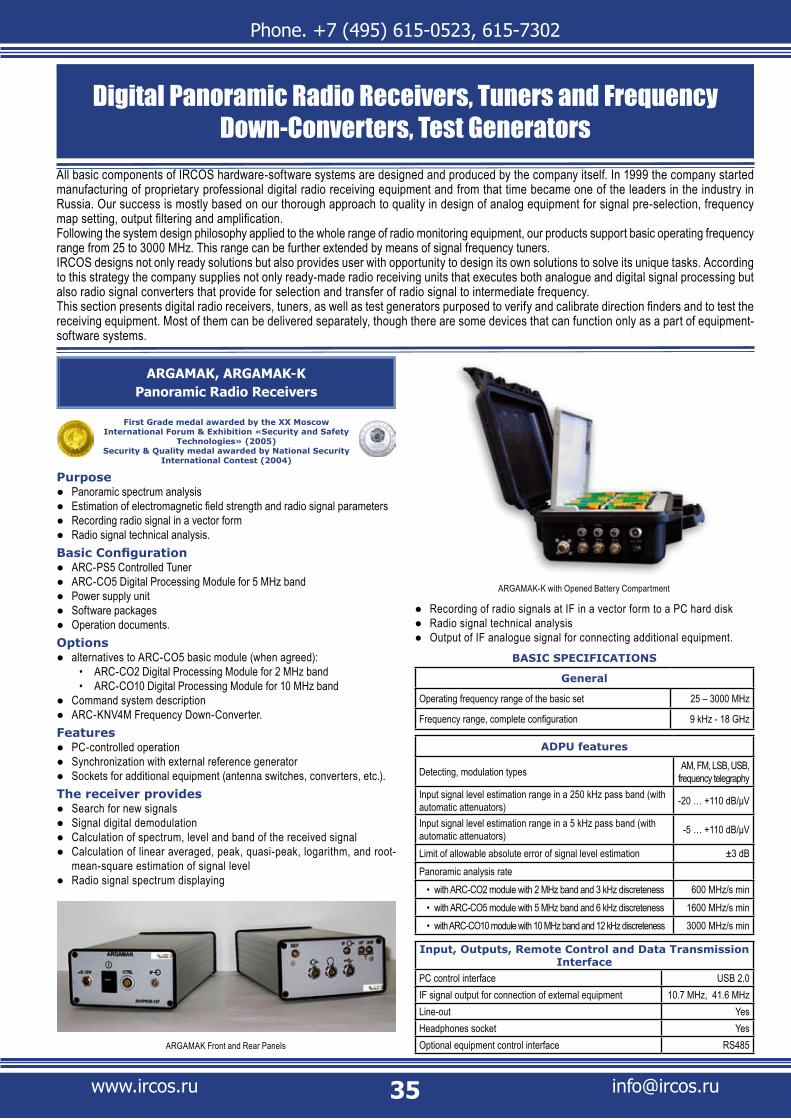
Phone. +7 (495) 615-0523, 615-7302
www.ircos.ru [email protected]
ARGAMAK, ARGAMAK-KPanoramic Radio Receivers
First Grade medal awarded by the XX Moscow International Forum & Exhibition «Security and Safety
Technologies» (2005)Security & Quality medal awarded by National Security
International Contest (2004)
PurposePanoramic spectrum analysis ●Estimation of electromagnetic field strength and radio signal parameters ●Recording radio signal in a vector form ●Radio signal technical analysis. ●
Basic ConfigurationARC-PS5 Controlled Tuner ●ARC-CO5 Digital Processing Module for 5 MHz band ●Power supply unit ●Software packages ●Operation documents. ●
Optionsalternatives to ARC-CO5 basic module (when agreed): ●
ARC-CO2 Digital Processing Module for 2 MHz band • ARC-CO10 Digital Processing Module for 10 MHz band•
Command system description ●ARC-KNV4M Frequency Down-Converter. ●
Features PC-controlled operation ●Synchronization with external reference generator ●Sockets for additional equipment (antenna switches, converters, etc.). ●
The receiver providesSearch for new signals ●Signal digital demodulation ●Calculation of spectrum, level and band of the received signal ●Calculation of linear averaged, peak, quasi-peak, logarithm, and root- ●mean-square estimation of signal level Radio signal spectrum displaying ●
Recording of radio signals at IF in a vector form to a PC hard disk ●Radio signal technical analysis ●Output of IF analogue signal for connecting additional equipment. ●
BASIC SPECIFICATIONS
General
Operating frequency range of the basic set 25 – 3000 MHz
Frequency range, complete configuration 9 kHz - 18 GHz
ADPU features
Detecting, modulation types AM, FM, LSB, USB, frequency telegraphy
Input signal level estimation range in a 250 kHz pass band (with automatic attenuators) -20 … +110 dB/μV
Input signal level estimation range in a 5 kHz pass band (with automatic attenuators) -5 … +110 dB/μV
Limit of allowable absolute error of signal level estimation ±3 dBPanoramic analysis rate
with ARC-CO2 module with 2 MHz band and 3 kHz discreteness• 600 MHz/s min with ARC-CO5 module with 5 MHz band and 6 kHz discreteness• 1600 MHz/s min with ARC-CO10 module with 10 MHz band and 12 kHz discreteness• 3000 MHz/s min
Input, Outputs, Remote Control and Data Transmission Interface
PC control interface USB 2.0IF signal output for connection of external equipment 10.7 MHz, 41.6 MHzLine-out YesHeadphones socket YesOptional equipment control interface RS485ARGAMAK Front and Rear Panels
ARGAMAK-K with Opened Battery Compartment
Digital Panoramic Radio Receivers, Tuners and Frequency Down-Converters, Test Generators
All basic components of IRCOS hardware-software systems are designed and produced by the company itself. In 1999 the company started manufacturing of proprietary professional digital radio receiving equipment and from that time became one of the leaders in the industry in Russia. Our success is mostly based on our thorough approach to quality in design of analog equipment for signal pre-selection, frequency map setting, output filtering and amplification.Following the system design philosophy applied to the whole range of radio monitoring equipment, our products support basic operating frequency range from 25 to 3000 MHz. This range can be further extended by means of signal frequency tuners.IRCOS designs not only ready solutions but also provides user with opportunity to design its own solutions to solve its unique tasks. According to this strategy the company supplies not only ready-made radio receiving units that executes both analogue and digital signal processing but also radio signal converters that provide for selection and transfer of radio signal to intermediate frequency.This section presents digital radio receivers, tuners, as well as test generators purposed to verify and calibrate direction finders and to test the receiving equipment. Most of them can be delivered separately, though there are some devices that can function only as a part of equipment-software systems.

Phone. +7 (495) 615-0523, 615-7302
www.ircos.ru [email protected]
Operating Temperature, Weight, Dimensions and Power Consumption
Operating temperature range -20°C … +50°C
Power supply voltage 10 - 15 V
Power consumption, max. 15 W
ARGAMAK-K Dimensions (width x height x depth) 272 x 248 x 122 mm
ARGAMAK Dimensions (width x height x depth) 106 x 56 x 236 mm
ARGAMAK Weight, max. 1.5 kg
ARGAMAK-K Weight, max. 5 kg
Radio receiving trunk is based on ARC-PS5.
ARGAMAK-M, ARGAMAK-MKSingle-Channel Radio Receiver
PurposeReceipt at fixed frequencies ●Recording radio signal in a vector form ●Radio signal technical analysis. ●
Basic ConfigurationARC-CPS1 Single Board Tuning and Digital Processing Module ●Power supply unit ●Software packages ●Operation documents. ●
OptionsCommand system descr ipt ion ●ARC-KNV4M Frequency Down-Conver ter ●
Features PC-controlled operation ●Synchronization with external reference generator ●Sockets for additional equipment (antenna switches, converters, etc.). ●
The receiver providesSearch for new signals ●Signal digital demodulation ●Calculation of spectrum, level and band of the received signal ●Calculation of linear averaged, peak, quasi-peak, logarithm, and root- ●mean-square estimation of signal level Recording of radio signals at IF in a vector form to a PC hard disk ●Radio signal technical analysis ●Output of IF analogue signal for connecting additional equipment. ●
ARGAMAK-M
BASIC SPECIFICATIONS
General
Operating frequency range of the basic set 25 – 3000 MHz
Frequency range, complete configuration 25 MHz – 18 GHz
Technical Specifications
Detecting, modulation types AM, FM, LSB, USB, frequency telegraphy
Input signal level estimation range in a 250 kHz pass band (with automatic attenuators) -20 … +110 dB/μV
Input signal level estimation range in a 5 kHz pass band (with automatic attenuators) -5 … +110 dB/μV
Limit of allowable absolute error of signal level estimationwithout calibration• ±3 dBwith calibration• ±1.5 dB
Panoramic analysis rate 1600 MHz/s min
Input, Outputs, Remote Control and Data Transmission Interface
PC control interface USB 2.0
IF signal output for connection of external equipment 41.6 MHz
Line-out Yes
Headphones socket Yes
Optional equipment control interface RS485
Operating Temperature, Weight, Dimensions and Power Consumption
Operating temperature range -20°C … +50°CPower supply voltage 10 - 15 VPower consumption max. 6 WARGAMAK-K Dimensions (width x height x depth) 272 x 248 x 122 mmARGAMAK-M Dimensions (width x height x depth) 107 x 44 x 220 mmARGAMAK-M Weight 1 kg, maxARGAMAK-MK Weight, max. 5 kg
Radio receiving trunk is based on ARC-PS5.
ARGAMAK-TSingle-Channel Tuner
PurposeFiltering, amplification and conversion of VLF, LF, MF, HF, VHF and UHF ●signals to an intermediate frequency.
Basic ConfigurationARC-PS5 controlled tuner in case ●Command system description ●Operation documents. ●
ARGAMAK-MK
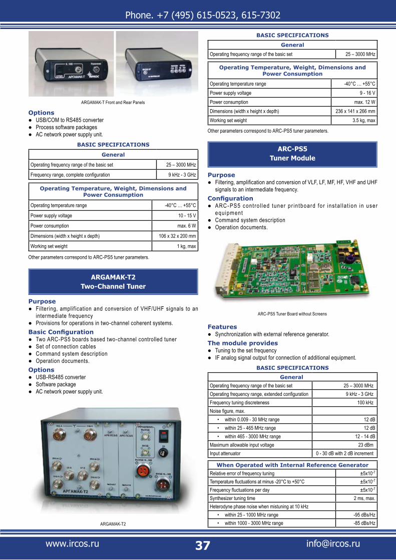
Phone. +7 (495) 615-0523, 615-7302
www.ircos.ru [email protected]
OptionsUSB/COM to RS485 converter ●Process software packages ●AC network power supply unit. ●
BASIC SPECIFICATIONS
General
Operating frequency range of the basic set 25 – 3000 MHz
Frequency range, complete configuration 9 kHz - 3 GHz
Operating Temperature, Weight, Dimensions and Power Consumption
Operating temperature range -40°C … +55°C
Power supply voltage 10 - 15 V
Power consumption max. 6 W
Dimensions (width x height x depth) 106 x 32 x 200 mm
Working set weight 1 kg, max
Other parameters correspond to ARC-PS5 tuner parameters.
ARGAMAK-T2Two-Channel Tuner
PurposeFiltering, amplif ication and conversion of VHF/UHF signals to an ●intermediate frequencyProvisions for operations in two-channel coherent systems. ●
Basic ConfigurationTwo ARC-PS5 boards based two-channel controlled tuner ●Set of connection cables ●Command system description ●Operation documents. ●
OptionsUSB-RS485 converter ●Software package ●AC network power supply unit. ●
BASIC SPECIFICATIONS
General
Operating frequency range of the basic set 25 – 3000 MHz
Operating Temperature, Weight, Dimensions and Power Consumption
Operating temperature range -40°C … +55°CPower supply voltage 9 - 16 VPower consumption max. 12 WDimensions (width x height x depth) 236 x 141 x 266 mmWorking set weight 3.5 kg, max
Other parameters correspond to ARC-PS5 tuner parameters.
ARC-PS5Tuner Module
Purpose Filtering, amplification and conversion of VLF, LF, MF, HF, VHF and UHF ●signals to an intermediate frequency.
ConfigurationARC - PS5 cont ro l led tuner p r intboard fo r ins ta l la t ion in user ●equipmentCommand system description ●Operation documents. ●
Features Synchronization with external reference generator. ●
The module providesTuning to the set frequency ●IF analog signal output for connection of additional equipment. ●
BASIC SPECIFICATIONS
GeneralOperating frequency range of the basic set 25 – 3000 MHzOperating frequency range, extended configuration 9 kHz - 3 GHzFrequency tuning discreteness 100 kHzNoise figure, max.
within 0.009 - 30 MHz range• 12 dBwithin 25 - 465 MHz range• 12 dBwithin 465 - 3000 MHz range• 12 - 14 dB
Maximum allowable input voltage 23 dBmInput attenuator 0 - 30 dB with 2 dB increment
When Operated with Internal Reference GeneratorRelative error of frequency tuning ±5х10-7
Temperature fluctuations at minus -20°C to +50°C ±5х10-7
Frequency fluctuations per day ±5х10-7
Synthesizer tuning time 2 ms, max.Heterodyne phase noise when mistuning at 10 kHz
within 25 - 1000 MHz range• -95 dBs/Hzwithin 1000 - 3000 MHz range• -85 dBs/Hz
ARGAMAK-T Front and Rear Panels
ARGAMAK-T2
ARC-PS5 Tuner Board without Screens

Phone. +7 (495) 615-0523, 615-7302
www.ircos.ru [email protected]
Selectivity and Harmonic Distortions
IF rejection 70 dB min
Image rejection 70 dB min
Intermodulation free dynamic range (3rd and 2nd order)
within 9 - 30 MHz range• 80 dB
within 25 - 3000 MHz range• 75 dB
Input IP3, without attenuators
within 9 - 30 MHz range• 6 dBm, min
within 25 - 3000 MHz range• 0 dBm, min
Input IP3 with 30 dB attenuator running
within 9 - 30 MHz range• 36 dBm, min
within 25 - 3000 MHz range• 30 dBm, min
Gain from input to IF output, dB 10 dB
Transfer factor irregularity within operating frequency range of basic modification ±3 dB max.
IF Signal
IF analogue signal frequency 10.7 or 41.6 MHz
Pass band before IF output:
10.7 MHz with ±1 dB variation• 2 MHz
41.6 MHz with ±1.5 dB variation• 5 MHz
Operating Temperature, Weight, Dimensions and Power Consumption
Operating temperature range –40°C … +55° C
Power supply voltage 9 - 16 V
Power consumption max. 6 W
Dimensions (width x height x depth) 100 x 16 x 168 mm
Working set weight 0.5 kg, max
ARC-CPS1Single Board Tuning and Digital Processing
Modules
PurposeRadio signal filtering, amplifying and transfer within frequency range ●from 25 - 3000 MHz to the intermediate frequency and A/D conversion of IF radio signalMultifunctional signal digital processing. ●
ConfigurationARC-CPS1 controlled tuner printboard for installation in user equipment ●Operation documents and command system descriptionд. ●
The module providesTuning to the set frequency ●IF analog signal output for connection of additional equipment ●Signal digital demodulation ●Calculation of spectrum, level and band of the received signal. ●
BASIC SPECIFICATIONS
Operating frequency range 25 – 3000 MHz
Frequency tuning discreteness 1 Hz,
Input attenuator 0 - 30 dB with 2 dB increment
Panoramic analysis rate 1600 MHz/s min
Dimensions 100 x 160 x 14 mm
Other specifications depend on ARC-PS5 and ARC-CO5 modules parameters
ARC-KNV4MRemote Controlled Frequency Down-Converter
PurposeFiltering, amplification and conversion of UHF and SHF signals to an ●intermediate frequency.
Basic ConfigurationRemote-mounted block with a frequency down-conver ter ●Set of cables ●Operation documents. ●
OptionsCommand system description ●USB-RS485 converter ●Utility software package ●AC network power supply unit. ●
BASIC SPECIFICATIONS
Received frequency range
with internal antenna:• 3 - 18 GHZ
with external antenna:• 1 - 18 GHZ
Output signal frequency 41.6 MHz
Relative error of frequency tuning ±5x10⁻⁷
Bandpass at -3 dB level 10 MHz min
Field sensitivity with internal antenna and 10 kHz band pass 50 μV/m min.
Gain factor for external antenna 0 dB
Gain error for external antenna, within operating frequency range ±6 dB max.Relative noise level induced by non-linear distortion of the 3rd order and mistuning between 10 MHz signals - for measuring receiver with 120 kHz bandpass
-68 dB max.
Spurious rejection for internal antenna 45 dB
Aperture angle for internal antenna at -3dB level 100° max.
Self-noise average level with 120 kHz band pass 1x10-13 W, max.
External antenna feed impedance 50 Ohm
SWR at external antenna input with 50 Ohm impedance 3 max
IF output impedance 50 Ohm
Output SWR with 50 Ohm impedance 2.5 max
Control interface RS485
Power supply 10 - 30 V
Power consumption max. 19 W
Converter weight 1.5 kg, max
Operating temperature range 0°С – 55°C
Dimensions, max. 220 x 220 x 150 mm
ARC-KNV4M Frequency Down-Converter
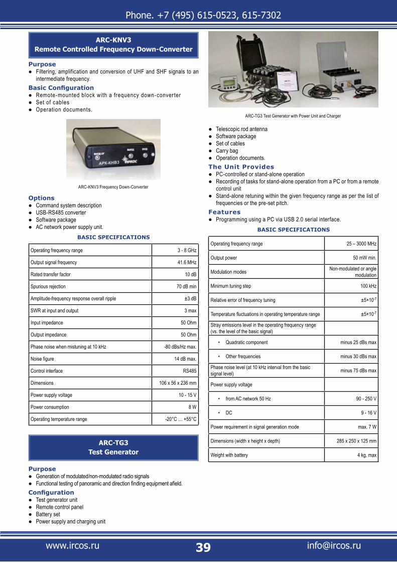
Phone. +7 (495) 615-0523, 615-7302
www.ircos.ru [email protected]
ARC-KNV3Remote Controlled Frequency Down-Converter
PurposeFiltering, amplification and conversion of UHF and SHF signals to an ●intermediate frequency.
Basic ConfigurationRemote-mounted block with a frequency down-conver ter ●Set of cables ●Operation documents. ●
OptionsCommand system description ●USB-RS485 converter ●Software package ●AC network power supply unit. ●
BASIC SPECIFICATIONS
Operating frequency range 3 - 8 GHz
Output signal frequency 41.6 MHz
Rated transfer factor 10 dB
Spurious rejection 70 dB min
Amplitude-frequency response overall ripple ±3 dB
SWR at input and output 3 max
Input impedance 50 Ohm
Output impedance 50 Ohm
Phase noise when mistuning at 10 kHz -80 dBs/Hz max.
Noise figure 14 dB max.
Control interface RS485
Dimensions 106 x 56 x 236 mm
Power supply voltage 10 - 15 V
Power consumption 8 W
Operating temperature range -20°C … +55°C
ARC-TG3Test Generator
PurposeGeneration of modulated/non-modulated radio signals ●Functional testing of panoramic and direction finding equipment afield. ●
ConfigurationTest generator unit ●Remote control panel ●Battery set ●Power supply and charging unit ●
Telescopic rod antenna ●Software package ●Set of cables ●Carry bag ●Operation documents. ●
The Unit ProvidesPC-controlled or stand-alone operation ●Recording of tasks for stand-alone operation from a PC or from a remote ●control unit Stand-alone retuning within the given frequency range as per the list of ●frequencies or the pre-set pitch.
FeaturesProgramming using a PC via USB 2.0 serial interface. ●
BASIC SPECIFICATIONS
Operating frequency range 25 – 3000 MHz
Output power 50 mW min.
Modulation modes Non-modulated or angle modulation
Minimum tuning step 100 kHz
Relative error of frequency tuning ±5×10⁻⁷
Temperature fluctuations in operating temperature range ±5×10⁻⁷
Stray emissions level in the operating frequency range (vs. the level of the basic signal)
Quadratic component • minus 25 dBs max
Other frequencies• minus 30 dBs max
Phase noise level (at 10 kHz interval from the basic signal level) minus 75 dBs max
Power supply voltage
from AC network 50 Hz• 90 - 250 V
DC• 9 - 16 V
Power requirement in signal generation mode max. 7 W
Dimensions (width x height x depth) 285 x 250 x 125 mm
Weight with battery 4 kg, max
ARC-TG3 Test Generator with Power Unit and Charger
ARC-KNV3 Frequency Down-Converter
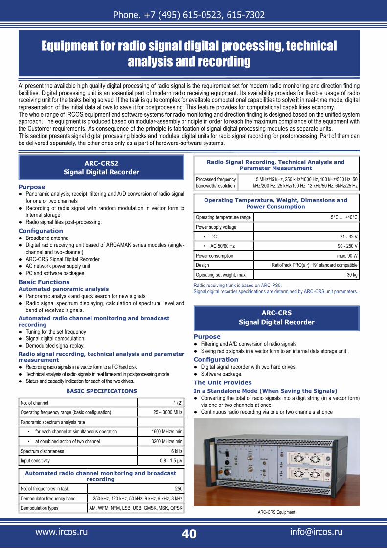
Phone. +7 (495) 615-0523, 615-7302
www.ircos.ru [email protected]
ARC-CRS2Signal Digital Recorder
PurposePanoramic analysis, receipt, filtering and A/D conversion of radio signal ●for one or two channelsRecording of radio signal with random modulation in vector form to ●internal storageRadio signal files post-processing. ●
Configuration Broadband antenna ●Digital radio receiving unit based of ARGAMAK series modules (single- ●channel and two-channel)ARC-CRS Signal Digital Recorder ●AC network power supply unit ●PC and software packages. ●
Basic FunctionsAutomated panoramic analysis
Panoramic analysis and quick search for new signals ●Radio signal spectrum displaying, calculation of spectrum, level and ●band of received signals.
Automated radio channel monitoring and broadcast recording
Tuning for the set frequency ●Signal digital demodulation ●Demodulated signal replay. ●
Radio signal recording, technical analysis and parameter measurement
Recording radio signals in a vector form to a PC hard disk ●Technical analysis of radio signals in real time and in postprocessing mode ●Status and capacity indication for each of the two drives. ●
BASIC SPECIFICATIONS
No. of channel 1 (2)
Operating frequency range (basic configuration) 25 – 3000 MHz
Panoramic spectrum analysis rate
for each channel at simultaneous operation• 1600 MHz/s min
at combined action of two channel• 3200 MHz/s min
Spectrum discreteness 6 kHz
Input sensitivity 0.8 - 1.5 μV
Automated radio channel monitoring and broadcast recording
No. of frequencies in task 250
Demodulator frequency band 250 kHz, 120 kHz, 50 kHz, 9 kHz, 6 kHz, 3 kHz
Demodulation types AM, WFM, NFM, LSB, USB, GMSK, MSK, QPSK
Equipment for radio signal digital processing, technical analysis and recording
At present the available high quality digital processing of radio signal is the requirement set for modern radio monitoring and direction finding facilities. Digital processing unit is an essential part of modern radio receiving equipment. Its availability provides for flexible usage of radio receiving unit for the tasks being solved. If the task is quite complex for available computational capabilities to solve it in real-time mode, digital representation of the initial data allows to save it for postprocessing. This feature provides for computational capabilities economy.The whole range of IRCOS equipment and software systems for radio monitoring and direction finding is designed based on the unified system approach. The equipment is produced based on modular-assembly principle in order to reach the maximum compliance of the equipment with the Customer requirements. As consequence of the principle is fabrication of signal digital processing modules as separate units.This section presents signal digital processing blocks and modules, digital units for radio signal recording for postprocessing. Part of them can be delivered separately, the other ones only as a part of hardware-software systems.
Radio Signal Recording, Technical Analysis and Parameter Measurement
Processed frequency bandwidth/resolution
5 MHz/15 kHz, 250 kHz/1000 Hz, 100 kHz/500 Hz, 50 kHz/200 Hz, 25 kHz/100 Hz, 12 kHz/50 Hz, 6kHz/25 Hz
Operating Temperature, Weight, Dimensions and Power Consumption
Operating temperature range 5°C … +40°C
Power supply voltage
DC• 21 - 32 V
AC 50/60 Hz• 90 - 250 V
Power consumption max. 90 W
Design RatioPack PRO(air), 19” standard compatible
Operating set weight, max 30 kg
Radio receiving trunk is based on ARC-PS5.Signal digital recorder specifications are determined by ARC-CRS unit parameters.
ARC-CRSSignal Digital Recorder
PurposeFiltering and A/D conversion of radio signals ●Saving radio signals in a vector form to an internal data storage unit . ●
Configuration Digital signal recorder with two hard drives ●Software package. ●
The Unit ProvidesIn a Standalone Mode (When Saving the Signals)
Converting the total of radio signals into a digit string (in a vector form) ●via one or two channels at once Continuous radio recording via one or two channels at once ●
ARC-CRS Equipment

Phone. +7 (495) 615-0523, 615-7302
www.ircos.ru [email protected]
Hot swapping of either hard drive without any impact to the recording ●Recording of operational and control data concurrently with the radio ●recording.
Under PC-Control (When Reading)Connection of the hard drives directly to the PC and displaying the data ●as filesSending continuous signal sampling data to a PC via USB 2.0 ●Sending block signal sampling data to a PC through USB 2.0 via one or ●two channels at once.
BASIC SPECIFICATIONS
Input signal central frequency 41.6 MHz
Frequency band width for signal set recording 5 MHz
Sampling rate 12.8 MHz
Register length within the digit string 12 (16)
Record length per drive, min 70 (40) min
Data transmission interface USB 2.0
RRU exchange interface RS-485
ARC-ACO-M11Two-channel A/D Processing Unit
PurposeFiltration and A/D conversion of IF radio signals ●Multifunctional digital processing of IF-signal ●Powering and control of antenna and receiving units. ●
Basic ConfigurationARC-CO5 Digital Signal Processing Module ●Set of cables ●Operation documents. ●
OptionsARC-C5 Special Processor ●ARC-KN1 Navigation and Mapping Module. ●
Features Input for synchronization with user equipment ●Stand-alone operation (without PC) with a manual control panel. ●
The unit provides (as a part of radiomonitoring equipment)
Incoming signal spectrum calculation ●Radio signal detection ●Bearing calculation ●Spectrum parameter calculation ●Signal digital demodulation ●Antenna system azimuth f inding when standing and when moving ●(available with ARC-KN2 Module).
BASIC SPECIFICATIONS
General
Input signal central frequency 41.6 MHz
Simultaneous bandwidth 5 MHz
Central frequency tuning interval 1 Hz,
Input signal level measuring range:
Within 5 MHz band• 0 … +90 dB/μV
Within 250 kHz Band• -15 … +90 dB/μV
Single-signal dynamic range within the 5 kHz band 90 dB min
Single-signal dynamic range within the 250 kHz band 105 dB min
Intermodulation free dynamic range (3rd and 2nd order) 80 dB min
Input, Outputs and Interfaces
PC control interface USB 2.0
Line-out Yes
Headphones socket Yes
Interface for antenna-receiver unit control RS485
Communication interface with control console RS485
Detecting, modulation types AM, FM, SSB, frequency telegraphy
Operating Temperature, Weight, Dimensions and Power Consumption
Operating temperature range -20°C ... +55°C
Power supply voltage 21 - 32 V
Power consumption:
Basic Configuration• max. 15 W
With ARC-C5 special processor• max. 35 W
Dimensions (width x height x depth) 236 x 141 x 266 mm
Operating set weight, max 5 kg
ARC-CO2, ARC-CO5, ARC-CO10Digital Signal Processing Modules
PurposeFiltration and A/D conversion of IF radio signals ●Multifunctional signal digital processing. ●
Basic ConfigurationDigital processing module on a printboard for installation in user's ●equipment.Operation documents and command system description. ●
Features PC-controlled operation ●Synchronization with external reference generator ●Coherent functioning of two or more modules. ●
The module providesTuning to the set frequency ●Signal digital demodulation ●Calculation of spectrum, level and band of the received signal. ●
Functions of Signal Level Measurement from Demodulator Output
Peak ●Quasi-Peak ●Logarithmic ●Root-mean-square. ●
ARC-ACO-M11 - Basic Configuration
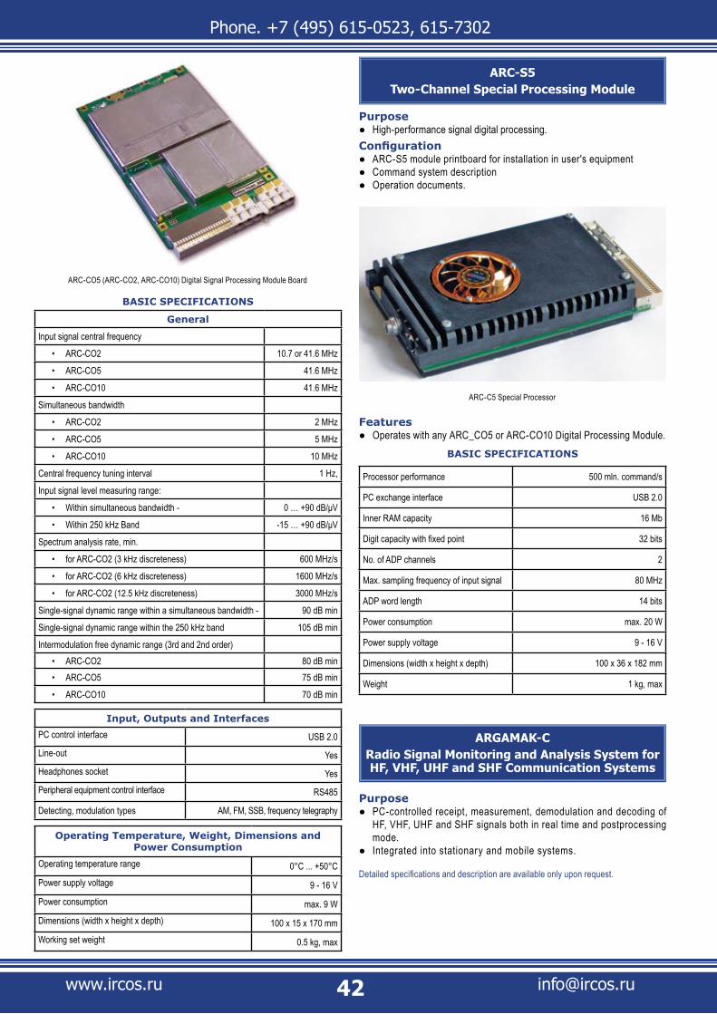
Phone. +7 (495) 615-0523, 615-7302
www.ircos.ru [email protected]
BASIC SPECIFICATIONS
General
Input signal central frequency
ARC-CO2• 10.7 or 41.6 MHz
ARC-CO5• 41.6 MHz
ARC-CO10• 41.6 MHz
Simultaneous bandwidth
ARC-CO2• 2 MHz
ARC-CO5• 5 MHz
ARC-CO10• 10 MHz
Central frequency tuning interval 1 Hz,
Input signal level measuring range:
Within simultaneous bandwidth -• 0 … +90 dB/μV
Within 250 kHz Band• -15 … +90 dB/μV
Spectrum analysis rate, min.
for ARC-CO2 (3 kHz discreteness)• 600 MHz/s
for ARC-CO2 (6 kHz discreteness)• 1600 MHz/s
for ARC-CO2 (12.5 kHz discreteness)• 3000 MHz/s
Single-signal dynamic range within a simultaneous bandwidth - 90 dB min
Single-signal dynamic range within the 250 kHz band 105 dB min
Intermodulation free dynamic range (3rd and 2nd order)ARC-CO2• 80 dB minARC-CO5• 75 dB min
ARC-CO10• 70 dB min
Input, Outputs and Interfaces
PC control interface USB 2.0Line-out YesHeadphones socket YesPeripheral equipment control interface RS485
Detecting, modulation types AM, FM, SSB, frequency telegraphy
Operating Temperature, Weight, Dimensions and Power Consumption
Operating temperature range 0°C ... +50°CPower supply voltage 9 - 16 VPower consumption max. 9 WDimensions (width x height x depth) 100 x 15 x 170 mmWorking set weight 0.5 kg, max
ARC-S5Two-Channel Special Processing Module
PurposeHigh-performance signal digital processing. ●
ConfigurationARC-S5 module printboard for installation in user's equipment ●Command system description ●Operation documents. ●
Features Operates with any ARC_CO5 or ARC-CO10 Digital Processing Module. ●
BASIC SPECIFICATIONS
Processor performance 500 mln. command/s
PC exchange interface USB 2.0
Inner RAM capacity 16 Mb
Digit capacity with fixed point 32 bits
No. of ADP channels 2
Max. sampling frequency of input signal 80 MHz
ADP word length 14 bits
Power consumption max. 20 W
Power supply voltage 9 - 16 V
Dimensions (width x height x depth) 100 x 36 x 182 mm
Weight 1 kg, max
ARGAMAK-C Radio Signal Monitoring and Analysis System for HF, VHF, UHF and SHF Communication Systems
PurposePC-controlled receipt, measurement, demodulation and decoding of ●HF, VHF, UHF and SHF signals both in real time and postprocessing mode. Integrated into stationary and mobile systems ● .
Detailed specifications and description are available only upon request.
ARC-CO5 (ARC-CO2, ARC-CO10) Digital Signal Processing Module Board
ARC-C5 Special Processor
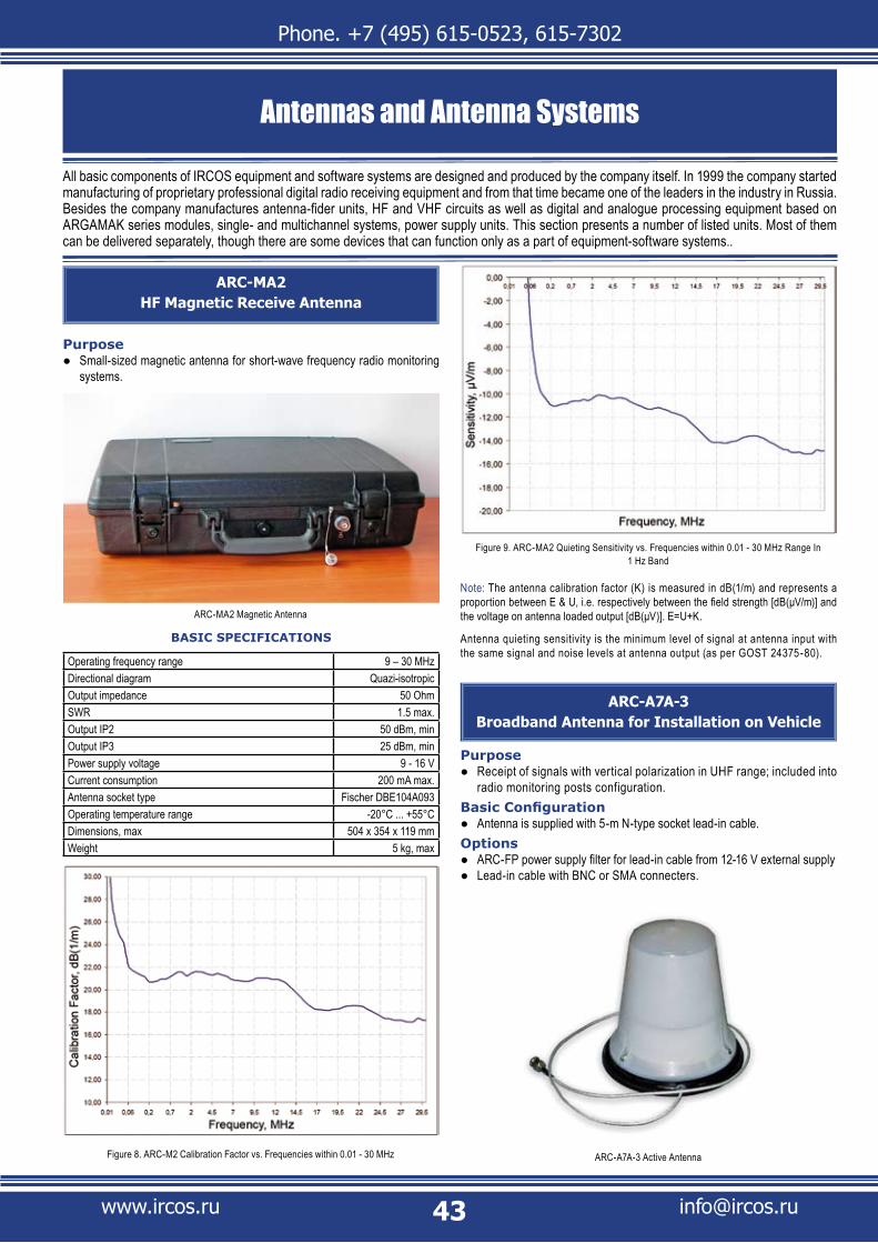
Phone. +7 (495) 615-0523, 615-7302
www.ircos.ru [email protected]
ARC-MA2 HF Magnetic Receive Antenna
PurposeSmall-sized magnetic antenna for short-wave frequency radio monitoring ●systems.
BASIC SPECIFICATIONS
Operating frequency range 9 – 30 MHzDirectional diagram Quazi-isotropicOutput impedance 50 OhmSWR 1.5 max.Output IP2 50 dBm, minOutput IP3 25 dBm, minPower supply voltage 9 - 16 VCurrent consumption 200 mA max.Antenna socket type Fischer DBE104A093Operating temperature range -20°C ... +55°C Dimensions, max 504 x 354 x 119 mmWeight 5 kg, max
Antennas and Antenna Systems
All basic components of IRCOS equipment and software systems are designed and produced by the company itself. In 1999 the company started manufacturing of proprietary professional digital radio receiving equipment and from that time became one of the leaders in the industry in Russia. Besides the company manufactures antenna-fider units, HF and VHF circuits as well as digital and analogue processing equipment based on ARGAMAK series modules, single- and multichannel systems, power supply units. This section presents a number of listed units. Most of them can be delivered separately, though there are some devices that can function only as a part of equipment-software systems..
Note: The antenna calibration factor (K) is measured in dB(1/m) and represents a proportion between E & U, i.e. respectively between the field strength [dB(μV/m)] and the voltage on antenna loaded output [dB(μV)]. E=U+K.
Antenna quieting sensitivity is the minimum level of signal at antenna input with the same signal and noise levels at antenna output (as per GOST 24375-80).
ARC-A7A-3 Broadband Antenna for Installation on Vehicle
PurposeReceipt of signals with vertical polarization in UHF range; included into ●radio monitoring posts configuration.
Basic ConfigurationAntenna is supplied with 5-m N-type socket lead-in cable. ●
OptionsARC-FP power supply filter for lead-in cable from 12-16 V external supply ●Lead-in cable with BNC or SMA connecters. ●
ARC-A7A-3 Active Antenna
ARC-MA2 Magnetic Antenna
Figure 8. ARC-M2 Calibration Factor vs. Frequencies within 0.01 - 30 MHz
Figure 9. ARC-MA2 Quieting Sensitivity vs. Frequencies within 0.01 - 30 MHz Range In 1 Hz Band
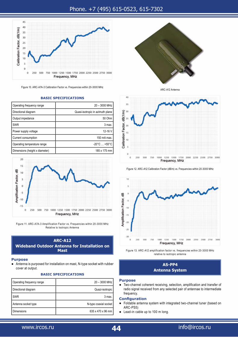
Phone. +7 (495) 615-0523, 615-7302
www.ircos.ru [email protected]
BASIC SPECIFICATIONS
Operating frequency range 20 – 3000 MHz
Directional diagram Quasi-isotropic in azimuth plane
Output impedance 50 Ohm
SWR 3 max.
Power supply voltage 12-16 V
Current consumption 150 mA max.
Operating temperature range -20°C … +55°C
Dimensions (height х diameter) 185 x 175 mm
ARC-A12Wideband Outdoor Antenna for Installation on
Mast
PurposeAntenna is purposed for installation on mast, N-type socket with rubber ●cover at output.
BASIC SPECIFICATIONS
Operating frequency range 20 – 3000 MHz
Directional diagram Quazi-isotropic
SWR 3 max.
Antenna socket type N-type coaxial socket
Dimensions 635 x 470 x 96 mm
AS-PP4Antenna System
PurposeTwo-channel coherent receiving, selection, amplification and transfer of ●radio signal received from any selected pair of antennae to intermediate frequency.
ConfigurationFoldable antenna system with integrated two-channel tuner (based on ●ARC-PS5) Lead-in cable up to 100 m long. ●
Figure 10. ARC-A7A-3 Calibration Factor vs. Frequencies within 20-3000 MHz
Figure 11. ARC-A7A-3 Amplif ication Factor vs. Frequencies within 20-3000 MHz Relative to Isotropic Antenna
ARC-A12 Antenna
Figure 12. ARC-A12 Calibration Factor (dB/m) vs. Frequencies within 20-3000 MHz
Figure 13. ARC-A12 amplif ication factor vs. frequencies within 20-3000 MHz relative to isotropic antenna
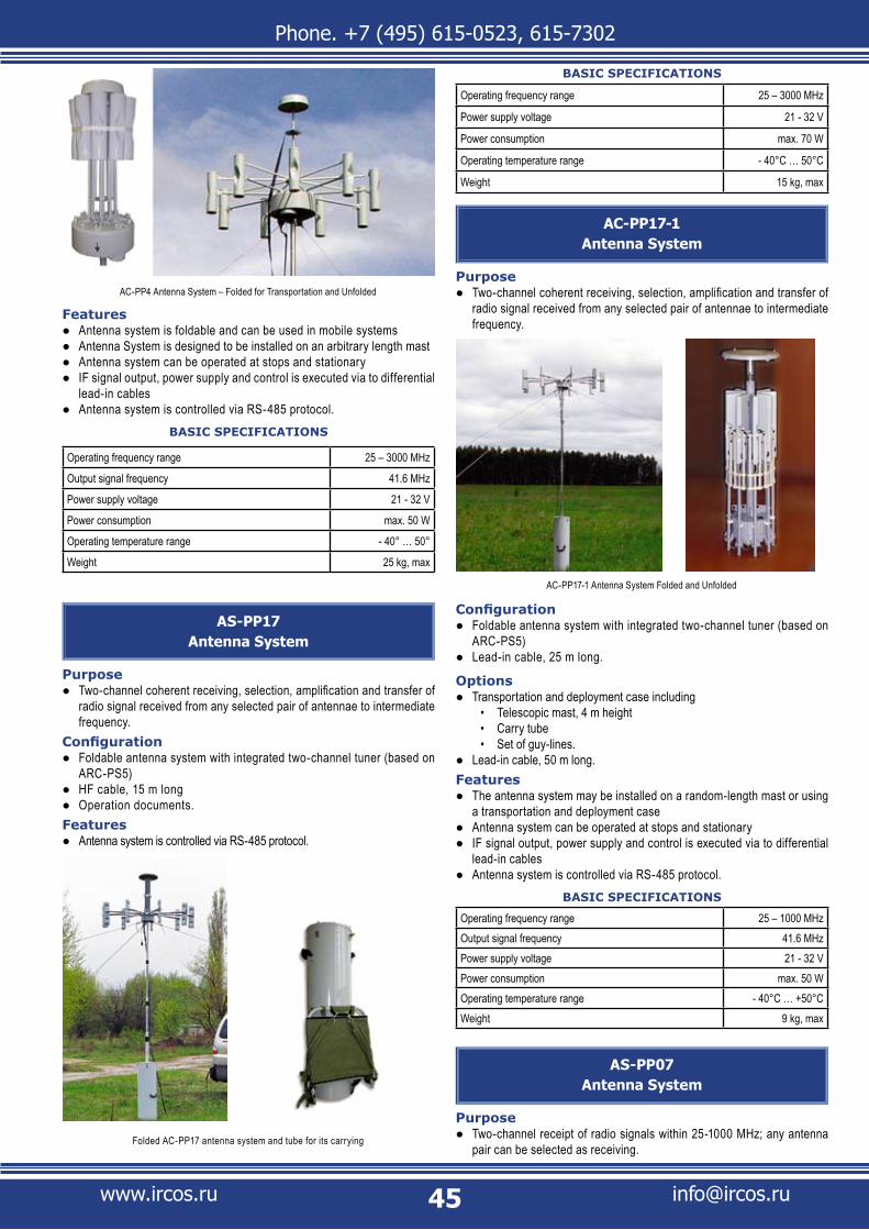
Phone. +7 (495) 615-0523, 615-7302
www.ircos.ru [email protected]
FeaturesAntenna system is foldable and can be used in mobile systems ●Antenna System is designed to be installed on an arbitrary length mast ●Antenna system can be operated at stops and stationary ●IF signal output, power supply and control is executed via to differential ●lead-in cables Antenna system is controlled via RS-485 protocol. ●
BASIC SPECIFICATIONS
Operating frequency range 25 – 3000 MHz
Output signal frequency 41.6 MHz
Power supply voltage 21 - 32 V
Power consumption max. 50 W
Operating temperature range - 40° … 50°
Weight 25 kg, max
AS-PP17Antenna System
PurposeTwo-channel coherent receiving, selection, amplification and transfer of ●radio signal received from any selected pair of antennae to intermediate frequency.
ConfigurationFoldable antenna system with integrated two-channel tuner (based on ●ARC-PS5)HF cable, 15 m long ●Operation documents. ●
FeaturesAntenna system is controlled via RS-485 protocol. ●
BASIC SPECIFICATIONS
Operating frequency range 25 – 3000 MHz
Power supply voltage 21 - 32 V
Power consumption max. 70 W
Operating temperature range - 40°C … 50°C
Weight 15 kg, max
AC-PP17-1Antenna System
PurposeTwo-channel coherent receiving, selection, amplification and transfer of ●radio signal received from any selected pair of antennae to intermediate frequency.
ConfigurationFoldable antenna system with integrated two-channel tuner (based on ●ARC-PS5) Lead-in cable, 25 m long. ●
OptionsTransportation and deployment case including ●
Telescopic mast, 4 m height• Carry tube• Set of guy-lines. •
Lead-in cable, 50 m long. ●Features
The antenna system may be installed on a random-length mast or using ●a transportation and deployment caseAntenna system can be operated at stops and stationary ●IF signal output, power supply and control is executed via to differential ●lead-in cables Antenna system is controlled via RS-485 protocol. ●
BASIC SPECIFICATIONS
Operating frequency range 25 – 1000 MHzOutput signal frequency 41.6 MHzPower supply voltage 21 - 32 VPower consumption max. 50 WOperating temperature range - 40°C … +50°CWeight 9 kg, max
AS-PP07Antenna System
PurposeTwo-channel receipt of radio signals within 25-1000 MHz; any antenna ●pair can be selected as receiving.
AC-PP4 Antenna System – Folded for Transportation and Unfolded
AC-PP17-1 Antenna System Folded and Unfolded
Folded AC-PP17 antenna system and tube for its carrying

Phone. +7 (495) 615-0523, 615-7302
www.ircos.ru [email protected]
ConfigurationAntenna System ●Lead-in cable ●4-m long telescopic mast and tube for carrying ●Set of guy-lines. ●
FeaturesAntenna system is portable. ●
BASIC SPECIFICATIONS
Operating frequency range 25 – 1000 MHz
Power supply voltage 21 - 32 V
Power consumption max. 20 W
Operating temperature range - 40°C … +50°C
Weight 8 kg, max
AS-MP17Antenna System
PurposeTwo-channel coherent receiving, selection, amplification and transfer of ●radio signal to intermediate frequency.
ConfigurationFoldable antenna system in radom with integrated two-channel tuner (based ●on ARC-PS5)Lead-in cable ●Antenna system mounting kit for vehicles. ●
FeaturesAntenna system is compact and can be installed on a light vehicle ●
Antenna system is removable and can be removed or mounted to vehicle roof ●when required Antenna system can be operated when moving and at stops ●IF signal output, power supply and control is executed via to differential lead-in ●cables Antenna system is controlled via RS-485 protocol. ●
BASIC SPECIFICATIONSOperating frequency range 25 – 3000 MHzOutput signal frequency 41.6 MHzPower supply voltage 21 - 32 VPower consumption max. 50 WOperating temperature range - 40° … +50°Dimensions (length x width x height) 1530 x 1090 x 343 mmWeight 30 kg, max
AS-MP07Antenna System
PurposeTwo-channel receipt of radio signals within 25-1000 MHz; any antenna ●pair can be selected as receiving.
ConfigurationAntenna system in radome ●Lead-in cable ●Antenna system mounting kit for vehicles. ●
FeaturesAntenna system is compact and can be installed on a light vehicle ●Antenna system is removable and can be removed or mounted to vehicle roof ●when required Antenna system can be operated when moving and at stops ●Antenna system is controlled via RS-485 protocol. ●
BASIC SPECIFICATIONSOperating frequency range 25 – 1000 MHzPower supply voltage 21 - 32 VPower consumption max. 20 WOperating temperature range - 40° … +50°Dimensions (length x width x height) 1530 x 1090 x 343 mmWeight 28 kg, max
ARC-MT1Turnable Dielectric Telescopic Mast
PurposeMeasurement antenna support ●Radio equipment support - e.g. for ARC-KNV4M Radio Signal Converter. ●
ConfigurationTelescopic mast ●Ground installation pad ●Set of pad fixing pins ●
AS-PP07 Antenna System mounted on the tube
AS-MP17 Antenna System
AC-MP07 Antenna System on Vehicle Roof
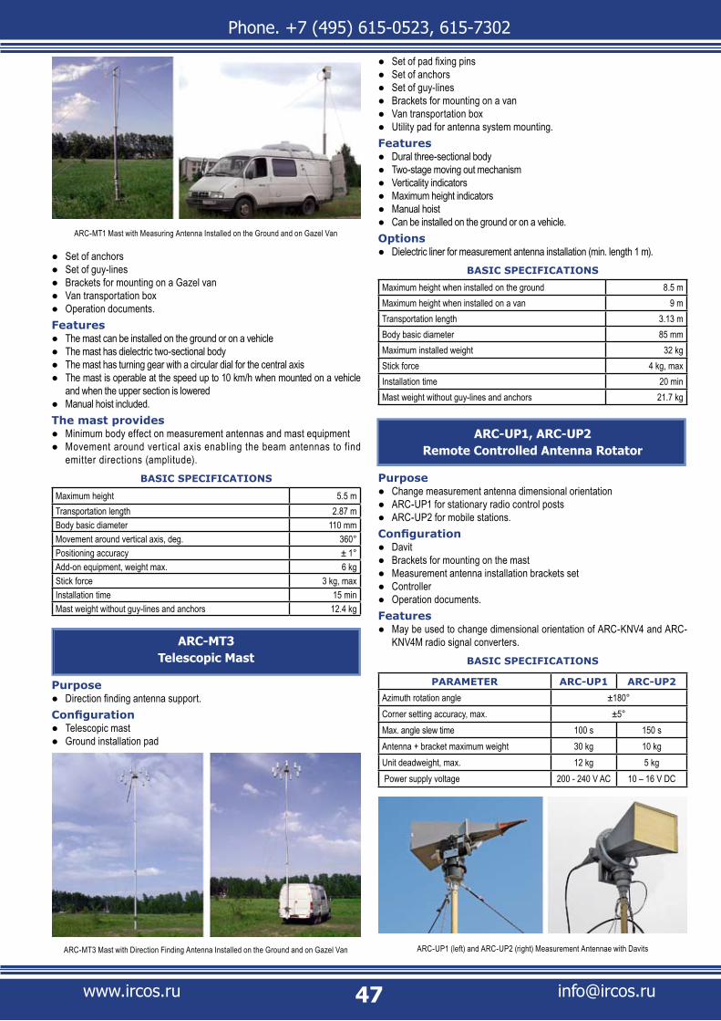
Phone. +7 (495) 615-0523, 615-7302
www.ircos.ru [email protected]
Set of anchors ●Set of guy-lines ●Brackets for mounting on a Gazel van ●Van transportation box ●Operation documents. ●
FeaturesThe mast can be installed on the ground or on a vehicle ●The mast has dielectric two-sectional body ●The mast has turning gear with a circular dial for the central axis ●The mast is operable at the speed up to 10 km/h when mounted on a vehicle ●and when the upper section is loweredManual hoist included. ●
The mast providesMinimum body effect on measurement antennas and mast equipment ●Movement around vertical axis enabling the beam antennas to f ind ●emitter directions (amplitude).
BASIC SPECIFICATIONS
Maximum height 5.5 mTransportation length 2.87 mBody basic diameter 110 mmMovement around vertical axis, deg. 360°Positioning accuracy ± 1°Add-on equipment, weight max. 6 kgStick force 3 kg, maxInstallation time 15 minMast weight without guy-lines and anchors 12.4 kg
ARC-MT3Telescopic Mast
PurposeDirection finding antenna support. ●
ConfigurationTelescopic mast ●Ground installation pad ●
Set of pad fixing pins ●Set of anchors ●Set of guy-lines ●Brackets for mounting on a van ●Van transportation box ●Utility pad for antenna system mounting. ●
FeaturesDural three-sectional body ●Two-stage moving out mechanism ●Verticality indicators ●Maximum height indicators ●Manual hoist ●Can be installed on the ground or on a vehicle. ●
OptionsDielectric liner for measurement antenna installation (min. length 1 m). ●
BASIC SPECIFICATIONS
Maximum height when installed on the ground 8.5 mMaximum height when installed on a van 9 mTransportation length 3.13 mBody basic diameter 85 mmMaximum installed weight 32 kgStick force 4 kg, maxInstallation time 20 minMast weight without guy-lines and anchors 21.7 kg
ARC-UP1, ARC-UP2Remote Controlled Antenna Rotator
PurposeChange measurement antenna dimensional orientation ●ARC-UP1 for stationary radio control posts ●ARC-UP2 for mobile stations. ●
ConfigurationDavit ●Brackets for mounting on the mast ●Measurement antenna installation brackets set ●Controller ●Operation documents. ●
FeaturesMay be used to change dimensional orientation of ARC-KNV4 and ARC- ●KNV4M radio signal converters.
BASIC SPECIFICATIONS
PARAMETER ARC-UP1 ARC-UP2
Azimuth rotation angle ±180°Corner setting accuracy, max. ±5°Max. angle slew time 100 s 150 sAntenna + bracket maximum weight 30 kg 10 kgUnit deadweight, max. 12 kg 5 kg Power supply voltage 200 - 240 V AC 10 – 16 V DC
ARC-MT3 Mast with Direction Finding Antenna Installed on the Ground and on Gazel Van
ARC-MT1 Mast with Measuring Antenna Installed on the Ground and on Gazel Van
ARC-UP1 (left) and ARC-UP2 (right) Measurement Antennae with Davits

Phone. +7 (495) 615-0523, 615-7302
www.ircos.ru [email protected]
Software
SMO-PAPanoramic Analysis Software Package Line
PurposeSMO-PA Software Packages are a part of customized software, panoramic ●analysis systems and detection systems for radio monitoring posts. SMO-PA Packages are designed for panoramic systems and panoramic direction finding systems.
FeaturesDesigned for MS Windows ●Receiving frequency bands, panoramic analysis rate and frequency ●resolution depend on receiving hardware SMO-PA Software Packages, subject to the type of the system, can ●support Spectrum, Panorama, Measurement, Direction Finding and Review mode.
The Software Packages Provide for the Following FunctionsSpectrum and Panorama mode
Real-time displaying of results of fast panoramic spectrum analysis ●Recording of accumulated spectrum files and frequency-time distribution ●Radio signals listening and saving demodulated signals to the hard disk ●Automatic search for active radio channels, saving of the detected ●frequencies to the databaseBackground monitoring of the detected radio channels ●Generating of reports with active channel search results. ●
Measurement ModeInteroperation with customized software for radio signals technical ●analysisOperation in spectral lens mode with resolution ranging between several ●dozens of kHz to dozens of Hz (if technical analysis equipment is available)Measurement of peak, quasi-peak and RMS strength of emitter electric ●
(magnetic) field components (if calibrated antennas are available) both in spectrum mode and in time sampling modeGenerating of measurement protocol for the coverage zone based on ●geographical coordinates (if calibrated antennas and positioning system are available)Precise automatic measurement of radio signal frequency, band and ●frequency distributionAutomatic and simultaneous identification of the type and parameters ●of radio signal modulation at the carrying frequency and subcarrier frequencyReal time transferring of field strength measurement results to the mapper ●application for coverage map drawing.
Bearing ModeSingle channel direction finding of radio signal sources ●
Most of IRCOS equipment are hardware-software combined systems. Most of calculations are conducted at the hardware level. However, system control, final data processing and output as required by user are performed by PC via proprietary customized software.Another feature of IRCOS equipment is multi-tasking supported just by the software, without any additional hardware.Equipment functions can be grouped as follows: radio signal panoramic analysis and direction finding, radio signal measurement, radio signal technical analysis, indoor radio monitoring, analysis of stray electromagnetic radiation and cross talks, emitter localization. Each group of functions is supported by its appropriate software package. For all equipment, the software interface is similar though there can be some differences subject to equipment.This section describes the general software packs designed for our catalog equipment.
SPECTRUM Window Screenshot
PANORAMA Window Screenshot
SMO-PA - MEASUREMENT Mode Screenshot

Phone. +7 (495) 615-0523, 615-7302
www.ircos.ru [email protected]
Multi-channel (parallel) direction finding of radio signal sources ●Displaying of bearings panorama, its saving to the database and to the ●frequency-time range loading file Filtering of radio signal sources for the set angle range and their displaying ●on spectrum and bearing panoramas. Transfer of direction finding results to mapper application. ●
Review ModeScanning of the preset list of frequencies, storage of scanning results ●(spectra, time-based samplings and sounds) in databases Generating of reports with review results ●Operation with database of recorded sources . ●
SMO Product Line Includes the Following Software Packages
SMO-PA ● - executive program for hardware of generation 3-5: ARC-D1TM, ARC-D11, ARGAMAK. Supports interaction of all units in panoramic analysis mode within 9 kHz - 18 GHz in real-time and postprocessing modes. Modes: Spectrum, Panorama, Measurement and Review
SMO-PAI ● - executive program for measurement hardware: ARC-D1TR, ARGAMAK-I, ARGAMAK-IM, ARGAMAK-IS. Supports interaction of all units in panoramic analysis mode within 9 kHz - 18 GHz in real-time and postprocessing modes. Modes: Spectrum, Panorama, Measurement and Review
SMO-PPK ● - executive program for ARTIKUL direction finder family. Supports interaction of all units in panoramic analysis and direction finding mode within 9 kHz - 18 GHz in real-time and postprocessing modes. Modes: Spectrum, Panorama, Measurement, Bearing and Review.
SMO-DXSoftware Package Line for Indoor Measuring
and Radio Monitoring
PurposeSMO-DX sof tware is a par t of customized sof tware for indoor ●measurements and rad io moni to r ing. Th is sof t ware ensures interaction of all equipment in a system during emitter detection and identif ication.
FeaturesDesigned for MS Windows ●Can be operated both as local and network application ●Provides for the following modes of operation ●
With reference panorama • With reference antenna•
Receiving frequency bands, panoramic analysis rate and frequency ●resolution depend on receiving hardware.
The Software Packages Provide for the Following FunctionsBasic Functions
Hardware system control ●On-line radio environment analysis ●Real-time spectrum analysis of radio signals and measuring their levels ●On-line panorama review (with its synchronous update) ●Recording accumulated spectrum files to the database ●Review and operation of the previously accumulated spectrum panorama ●Finding and identification of new radio emitters ●Identification of different radio emissions ●Saving of the new and identified emitter parameters to the database ●
REVIEW Window Screenshot
SMO-PPK - BEARING Mode Screenshot
SMO-PAI - MEASUREMENT Mode Screenshot
Signal Spectrum Detailing Screenshot

Phone. +7 (495) 615-0523, 615-7302
www.ircos.ru [email protected]
Operation with recorded emitters database ●Report generation based on operation results. ●
Functions Available with Wire Network AnalysisHigh-frequency signal spectrum analysis in AC network and other wire ●networks High/low-frequency signal detection in wire networks. ●
Packages are designed for radio monitoring equipment (ARC-D1TM-8, ARC-D11).
SMO-PPAPanoramic Analysis Software Package
PurposeSMO-PPA package is a part of customized software for handheld ●radio monitoring equipment. SMO-PPA package is designed to control handheld equipment via a PDA.
FeaturesDesigned for Pocket PC operation system ●Receiving frequency bands, panoramic analysis rate and frequency ●resolution depend on receiving hardware and PDA parameters Can process spectrum data in a real-time mode and accumulate them ●for post-processing Enables measurement of radio signal parameters & electromagnetic field ●strength (with measurement antennas) with reference to geographic coordinates.
The Software Package Provides for the Following Functions
Real-time displaying of results of fast panoramic spectrum analysis ●Automatic direction finding ●
Frequency-time loading recording ●Demodulated radio signal listening ●Measurement of radio signal parameters & electromagnetic f ield ●strength (with measurement antennas) with reference to geographic coordinatesGenerating of reports with measuring results ●Review of pre-set frequency list, listening of active channels. ●
SMO-STARadio Signal Technical Analysis Package
PurposeSMO-STA software is designed for radio signals technical analysis, ●measurement and identification of their modulation type.The software provides for signal saving in a vector form, their analysis at ●a given frequency, analysis of detected signals and subcarrier signals.
FeaturesDesigned for MS Windows ●Can be operated both as local and network application. ●Can perform analysis in two modes – in real time mode (the signal is ●displayed as it is received from the equipment), and in post-processing mode (the data are taken from the file).
The Software Package Provides for the Following Functions
Recording radio signal fragments in a vector form ●Signal displaying with time and amplitude scaling ●Signal spectra displaying with different resolution and frequency scaling ●Signal band filtration ●
DETECTION Window Screenshot
SMO-PPA Interface Screenshot
SMO-STA Screenshot
Signal Technical Analysis Screenshot – SMO-STA Assisted, in Real Time Mode

Phone. +7 (495) 615-0523, 615-7302
www.ircos.ru [email protected]
Signal frequency shift (for more accurate tuning and demodulation of ●subcarrier signals) Detection of carrier frequency signals (amplitude, frequency and phase ●detectors) Detection of subcarrier frequency signals (amplitude, frequency and phase ●detectors) Identification of signal frequency and time parameters ●Identification of signal band width ●Signal special conversion to determine phase modulation ●Displaying of signal time-and-amplitude histograms to determine digital ●modulation types Displaying of maximum and minimum deviation curves to determine the ●signal structure Equipment control and signal recording to the hard disk. ●
SMO-STA software package supports any equipment that provides for radio signal recording and technical analysis.
SMO-ASPDSoftware Package for Spectrum and Bearing
Data Analysis
PurposeSpectrum and Bearing Data Analysis (SMO-ASPD) software package ●is designed for playback and post-processing of spectrum analysis results obtained during operation with SMO-PA application.
FeaturesDesigned for MS Windows. ●
The Software Package Provides for the Following Functions
Display of accumulated spectrum and direction f inding data with ●adjustable frequency and time resolution as:
Current spectrum diagrams • Current bearing diagrams • Peak spectrum diagrams • of the FTD •
Search for communication sessions and evaluation of main radio ●environment parameters for a given channel set Processing results displaying as: ●
Radio channel load diagram • Diagram of average communication session time • Inter-correlation and simplex-correlation diagram.•
The software is compatible with all equipment controlled via SMO-PA package.
SMO-KNCartography and Navigation Software Package
Line
PurposeSMO-KN is a special geoinformational system designed to locate emitters, ●show them in electronic maps (electronic maps to be provided by the customer) along with other radio environment elements and to display the EM field strength values based on theoretical calculations and on-site measurement.
FeaturesThe software is compatible with MS Windows. ●Can be operated both as local and network application ●Support manual and automatic operation ●Can be included into ●
Separate software and hardware systems (stationary, mobile, • handheld) Distributed systems comprising several systems • Standalone units.•
The Software Package Provides for the Following Functions
Simultaneous loading of geographic map, radio environment map, ●emitters map and matrix mapShowing in the map direction finders position and orientation, emitter ●positions and parameters, bearings, bearing pie charts, calculated
SMO-ASPD Software Package Screenshot
Screenshot - Map of Local Electromagnetic Environment and Field Strength Values for Traffic Points
Emitter Position Finding and Displaying in the Map along with Station Traffic Route, EM Field Strength Diagram and Static Bearings
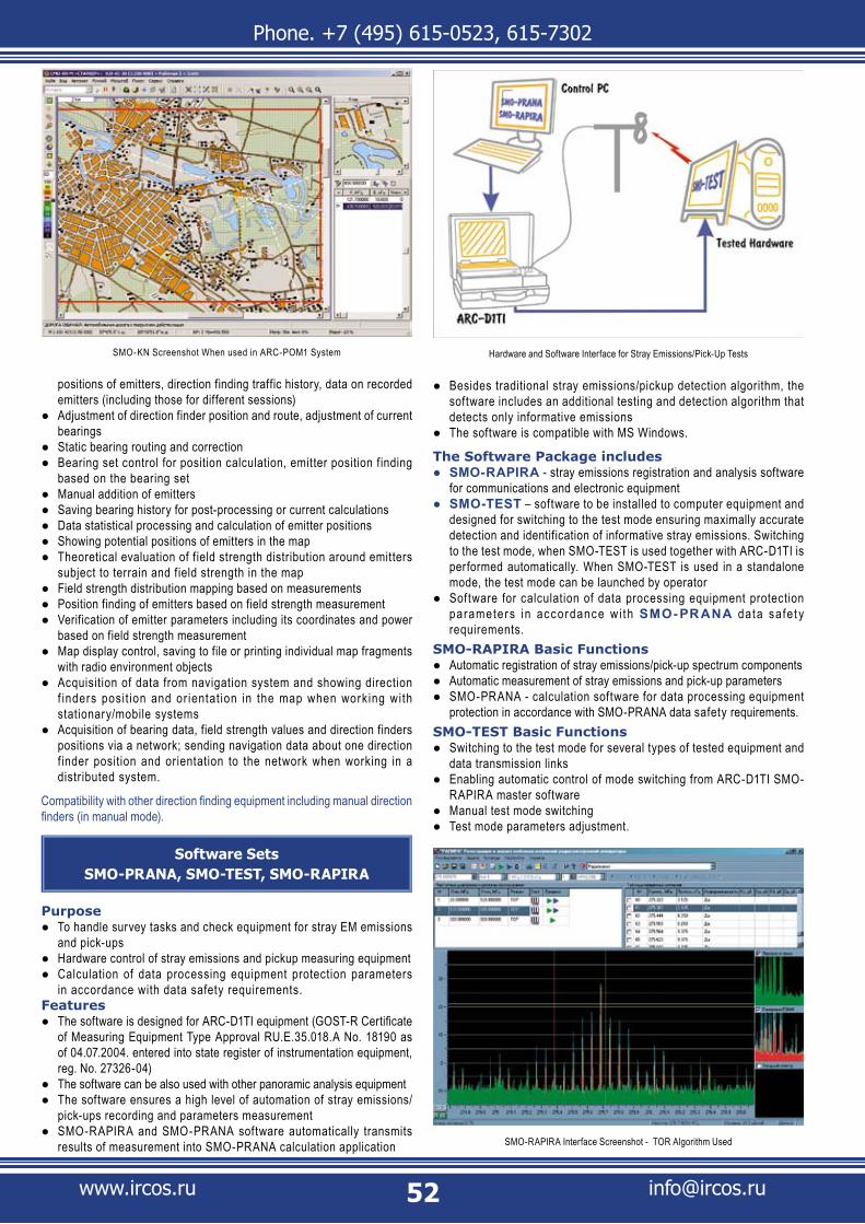
Phone. +7 (495) 615-0523, 615-7302
www.ircos.ru [email protected]
positions of emitters, direction finding traffic history, data on recorded emitters (including those for different sessions)Adjustment of direction finder position and route, adjustment of current ●bearingsStatic bearing routing and correction ●Bearing set control for position calculation, emitter position f inding ●based on the bearing setManual addition of emitters ●Saving bearing history for post-processing or current calculations ●Data statistical processing and calculation of emitter positions ●Showing potential positions of emitters in the map ●Theoretical evaluation of f ield strength distribution around emitters ●subject to terrain and field strength in the mapField strength distribution mapping based on measurements ●Position finding of emitters based on field strength measurement ●Verification of emitter parameters including its coordinates and power ●based on field strength measurementMap display control, saving to file or printing individual map fragments ●with radio environment objectsAcquisition of data from navigation system and showing direction ●f inders posit ion and or ientat ion in the map when working with stationary/mobile systemsAcquisition of bearing data, field strength values and direction finders ●positions via a network; sending navigation data about one direction f inder position and orientation to the network when working in a distributed system.
Compatibility with other direction finding equipment including manual direction finders (in manual mode).
Software SetsSMO-PRANA, SMO-TEST, SMO-RAPIRA
PurposeTo handle survey tasks and check equipment for stray EM emissions ●and pick-upsHardware control of stray emissions and pickup measuring equipment ●Calculation of data processing equipment protection parameters ●in accordance with data safety requirements.
FeaturesThe software is designed for ARC-D1TI equipment (GOST-R Certificate ●of Measuring Equipment Type Approval RU.E.35.018.A No. 18190 as of 04.07.2004. entered into state register of instrumentation equipment, reg. No. 27326-04)The software can be also used with other panoramic analysis equipment ●The software ensures a high level of automation of stray emissions/ ●pick-ups recording and parameters measurementSMO-RAPIRA and SMO-PRANA software automatically transmits ●results of measurement into SMO-PRANA calculation application
Besides traditional stray emissions/pickup detection algorithm, the ●software includes an additional testing and detection algorithm that detects only informative emissionsThe software is compatible with MS Windows. ●
The Software Package includesSMO-RAPIRA ● - stray emissions registration and analysis software for communications and electronic equipmentSMO-TEST ● – software to be installed to computer equipment and designed for switching to the test mode ensuring maximally accurate detection and identification of informative stray emissions. Switching to the test mode, when SMO-TEST is used together with ARC-D1TI is performed automatically. When SMO-TEST is used in a standalone mode, the test mode can be launched by operatorSoftware for calculation of data processing equipment protection ●parameters in accordance w i th SMO-PR ANA data safet y requirements.
SMO-RAPIRA Basic FunctionsAutomatic registration of stray emissions/pick-up spectrum components ●Automatic measurement of stray emissions and pick-up parameters ●SMO-PRANA - calculation software for data processing equipment ●protection in accordance with SMO-PRANA data safety requirements.
SMO-TEST Basic FunctionsSwitching to the test mode for several types of tested equipment and ●data transmission linksEnabling automatic control of mode switching from ARC-D1TI SMO- ●RAPIRA master software Manual test mode switching ●Test mode parameters adjustment. ●
SMO-KN Screenshot When used in ARC-POM1 System Hardware and Software Interface for Stray Emissions/Pick-Up Tests
SMO-RAPIRA Interface Screenshot - TOR Algorithm Used
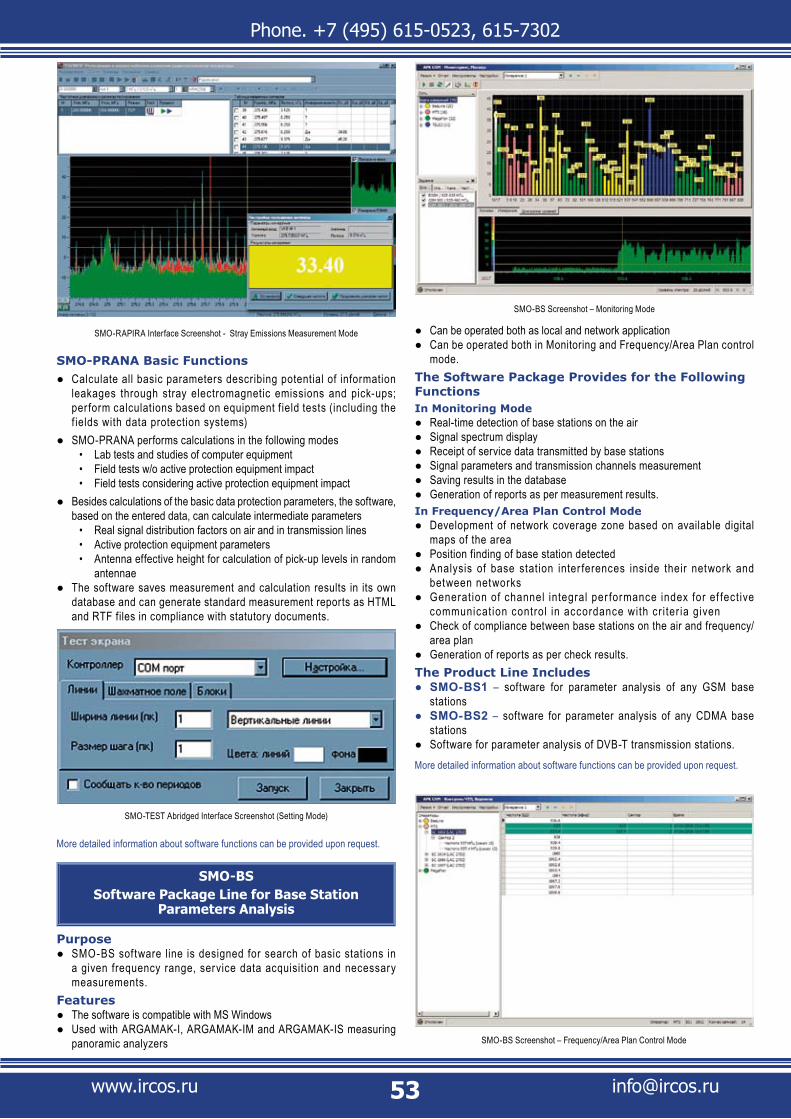
Phone. +7 (495) 615-0523, 615-7302
www.ircos.ru [email protected]
SMO-PRANA Basic FunctionsCalculate all basic parameters describing potential of information ●leakages through stray electromagnetic emissions and pick-ups; per form calculations based on equipment f ield tests (including the f ields with data protection systems)SMO-PRANA performs calculations in the following modes ●
Lab tests and studies of computer equipment • Field tests w/o active protection equipment impact• Field tests considering active protection equipment impact•
Besides calculations of the basic data protection parameters, the software, ●based on the entered data, can calculate intermediate parameters
Real signal distribution factors on air and in transmission lines • Active protection equipment parameters• Antenna effective height for calculation of pick-up levels in random • antennae
The software saves measurement and calculation results in its own ●database and can generate standard measurement reports as HTML and RTF files in compliance with statutory documents.
More detailed information about software functions can be provided upon request.
SMO-BSSoftware Package Line for Base Station
Parameters Analysis
PurposeSMO-BS software line is designed for search of basic stations in ●a given frequency range, service data acquisition and necessary measurements.
FeaturesThe software is compatible with MS Windows ●Used with ARGAMAK-I, ARGAMAK-IM and ARGAMAK-IS measuring ●panoramic analyzers
Can be operated both as local and network application ●Can be operated both in Monitoring and Frequency/Area Plan control ●mode.
The Software Package Provides for the Following FunctionsIn Monitoring Mode
Real-time detection of base stations on the air ●Signal spectrum display ●Receipt of service data transmitted by base stations ●Signal parameters and transmission channels measurement ●Saving results in the database ●Generation of reports as per measurement results. ●
In Frequency/Area Plan Control ModeDevelopment of network coverage zone based on available digital ●maps of the areaPosition finding of base station detected ●Analysis of base station inter ferences inside their network and ●between networksGenerat ion of channel integral per formance index for ef fect ive ●communicat ion control in accordance with cr i ter ia given Check of compliance between base stations on the air and frequency/ ●area planGeneration of reports as per check results. ●
The Product Line IncludesSMO-BS1 ● – software for parameter analysis of any GSM base stationsSMO-BS2 ● – software for parameter analysis of any CDMA base stationsSoftware for parameter analysis of DVB-T transmission stations. ●
More detailed information about software functions can be provided upon request.
SMO-TEST Abridged Interface Screenshot (Setting Mode)
SMO-RAPIRA Interface Screenshot - Stray Emissions Measurement Mode
SMO-BS Screenshot – Monitoring Mode
SMO-BS Screenshot – Frequency/Area Plan Control Mode