
Catalogue ACOUSTICS Product - SDG Construction
97
ESSENTIAL COMPONENTS FOR EVERY STAGE OF CONSTRUCTION Product Catalogue
Transcript of Catalogue ACOUSTICS Product - SDG Construction

AC
OU
ST
ICS
1ESSENTIAL COMPONENTS FOR EVERY STAGE OF CONSTRUCTION
Product Catalogue

2
SD
G P
RO
DU
CT
CA
TAL
OG
UE
SD
G P
RO
DU
CT
CA
TAL
OG
UE
Welcome to SDG.Your essential construction partner.
We work with manufacturers, contractors, engineers and
designers, supplying essential components that improve
safety, enhance quality and drive efficiency at every stage
of construction.
At SDG we are trusted suppliers, and experts in construction
solutions. We are planners, collaborators and designers;
fixers, thinkers and expert problem solvers. We’re an end-to-end
construction project partner, bespoke and best in class.
By working closely with our customers; by adding value at
every stage; by doing everything they expect and so much more,
we share their success and become stronger, together.
TECHNICAL INNOVATION
PRECAST ACCESSORIES
CONSTRUCTION ACCESSORIES
WATERPROOFING
ACOUSTICS
Stronger, together.

SD
G P
RO
DU
CT
CA
TAL
OG
UE
46
Precast Accessories
SECTION CONTENTS
Contact our sales team:
wearesdg.com
+44 (0) 28 3752 8999
Precast Magnet Systems 46
Double Wall Products 53
Connection Systems 57
Lifting Sockets Systems 60
Lifting with Spread Anchor Systems 134
Lifting with Spherical Anchor Systems 174
Precast Plastic Accessories 224
Concrete Structural Fibres 227

PR
EC
AS
T A
CC
ES
SO
RIE
S
49
SD
G P
RO
DU
CT
CA
TAL
OG
UE
48
MultiForm is a robust and flexible shuttering support
system for producing the various precast elements
including:
– Manufacturing solid and sandwich walls
– Manufacturing landing slabs, beams and joists
– Use on tilting table, formwork table, circulation
palettes and wooden surfaces.
Using MagFly® magnets, MulitForm can be moved easily
on the formwork table and positioned precisely. As the
MagFly® AP presses the MultiForm onto the formwork
table, the joints are sealed as soon as the magnets are
activated when a PE chamfer profile is used. Additional
sealing with silicone is therefore unnecessary.
A window and door opening suitable for MultiForm
offers a clever solution for enclosed openings in
concrete elements. Using elements that can be taken
out from the inside of the structure, the shuttering can
be removed non-destructively for reuse. The built-
in socket for the MagFly® magnets enables fast and
precise assembly and disassembly of the shuttering.
PRECAST MAGNET SYSTEMS
SDG are BT Innovation GmbH distribution partner
for the UK and Ireland. Together we provide a range
of specialist shuttering magnets, formwork and
connecting systems for the Precast Industry.
Magnetic Formwork SystemsMulti Form
The advantages of the MultiForm formwork include:
– Can be used quickly and ergonomically
– No sealing with silicone between the formwork shell and the formwork table
– Stable and robust system - designed for use in precast plants
– The window and door openings can be disassembled from the inside
small column for short shuttering e.g. recesses
column for long shuttering Up to 80cm tall & 3,025m long
shuttering element for window and door corners
MULTIFORM TYPE 1
MULTIFORM TYPE 2
WINDOW & DOOR OPENING
MULTIFORM MFE (CORNER JOINT)
OVERVIEW TABLE OVERLEAF

PR
EC
AS
T A
CC
ES
SO
RIE
S
SD
G P
RO
DU
CT
CA
TAL
OG
UE
50 51
PRODUCT CODE DESCRIPTIONWEIGHT
[KG]
DIMENSIONS (MM)
L B H
8101050 MultiForm Type 1 – formwork angle H70 1.39 280 110 70
8101139 MultiForm Type 1 – formwork angle H90 1.75 280 110 90
8101155 MultiForm Type 1 – formwork angle H148 1.83 280 115 148
8101144 MultiForm Type 1 – formwork angle H190 2.11 280 115 190
8101165 MultiForm Type 1 – formwork angle H248 2.47 280 115 248
8101207 MultiForm Type 1 – formwork angle H290 3.43 280 205 290
8101471 MultiForm Type 1 – formwork angle H350 4.06 280 255 350
8101208 MultiForm Type 1 – formwork angle H390 4.35 280 266 390
8101470 MultiForm Type 1 – formwork angle H440 6.36 280 255 440
8101469 MultiForm Type 1 – formwork angle H490 6.96 280 255 490
8101468 MultiForm Type 1 – formwork angle H540 7.4 280 255 540
8101467 MultiForm Type 1 – formwork angle H590 7.96 280 255 590
8101466 MultiForm Type 1 – formwork angle H640 8.58 280 255 640
8101451 MultiForm Type 1 – formwork angle H690 9.56 280 255 690
8101063 MultiForm Type 2 – 98/3025 12.2 3,025 150 98
8101085 MultiForm Type 2 – 148/3025 16.4 3,025 150 148
8101096 MultiForm Type 2 – 198/3025 19.4 3,025 150 198
8101107 MultiForm Type 2 – 248/3025 23.3 3,025 200 248
8101118 MultiForm Type 2 – 298/3025 25 3,025 200 298
8101122 MultiForm Type 2 – 348/3025 30 3,025 200 348
8101123 MultiForm Type 2 – 398/3025 34.1 3,025 250 398
8101125 MutliForm Type 2 – 448/3025 36.1 3,025 250 448
8101127 MultiForm Type 2 – 498/3025 38 3,025 250 498
8101379 MultiForm Type 2 – 548/3025 44.5 3,025 250 548
8101290 MultiForm Type 2 – 598/3025 47 3,025 250 598
8101205 MultiForm Type 2 – 698/3025 51.6 3,025 300 698
8101063100 MultiForm Type 2 – 98/3000 double 25.5 3,000 350 98
8101085200 MultiForm Type 2 – 148/3000 double 33 3,000 350 148
8101096200 MultiForm Type 2 – 198/3000 double 43 3,000 400 198
8101107200 MultiForm Type 2 – 248/3000 double 46 3,000 400 248
8101118200 MultiForm Type 2 – 298/3000 double 49.83 3,000 400 298
8101118300 MultiForm Type 2 – 298/3000 double 49.7 3,000 350 298
8101122300 MultiForm Type 2 – 348/3000 double 56.22 3,000 350 348
PRECAST ACCESSORIES > PRECAST MAGNET SYSTEMS
The MagFly® AP is a patented shuttering magnet and
a component of the BT shuttering formwork system.
Unique features include the magnetic force-to-weight
ratio, plus the unique foot/spring system, which allows
the magnet to slide easily over the formwork table.
The magnet is activated by a firm pressure from above
and adheres to the formwork table by its magnetic
force. The MagFly® AP can be detached and realigned
simply and quickly using the integrated lever. It does
not require any additional tools or adapters.
The ultra-light aluminium casing makes ergonomic
work with the magnets possible and saves effort by
the user. In combination with the MultiForm formwork
girders and an additional plastic chamfer profile, the
formwork girder and chamfer profile are pressed firmly
to the formwork table when the magnets are activated.
An additional sealing for the edge is not neccessary.
These effective technologies are matched perfectly to
each other and substantially speed up the production
of precast concrete elements.
Applications:
– Shuttering magnets for pallet circulation systems
and tilting tables
– Shuttering for walls, beams, etc.
PRODUCT CODE DESCRIPTION SIZE
BTI055 Magfly AP (Adhesive Power) 2200Kg Each
Magfly® APShuttering magnets featuring patented foot/spring system for positioning and detaching
Benefits:
– Patented shuttering fastening provides increased retention pressure for shuttering at the formwork table
– No silicone sealant required
– Light and ergonomic handling thanks to the foot/spring system
– Magnet and formwork girder perfectly matched
– Unbeatable adhesive force-to-weight ratio
Multi Form

PR
EC
AS
T A
CC
ES
SO
RIE
S
SD
G P
RO
DU
CT
CA
TAL
OG
UE
52 53
The KU magnet is used for holding ball-headed
anchors. Depending on the size of the ball-headed
anchor, we offer the magnets to fit with the optimum
magnetic force in our range of products.
In order to attach the ball-headed anchor to the
magnet, the appropriate rubber holding band is
supplied in each case. The steel body is turned from
high quality solid material and forms a homogeneous
unit with the high performance core of the magnet. The
attachment surface is completely sealed and therefore
protects the core of the magnet against corrosion
and damage. This increases the working life of the
magnetic force considerably. The integrated internal
thread allows the magnet to be smoothly released from
the steel table.
Benefits:
– Combined recess former with magnet
– Internal thread for releasing the magnet
– Solid and stable construction due to steel base body, thus long service life
– Environmentally friendly and cost-effective due to reusability.
PRODUCT CODE DESCRIPTION SIZE
BTI001 Magnetic Former 2.5T KU25 Complete With O Ring Each
BTI002 Magnetic Former 5T KU50 Complete with O Ring Each
BTI005 Magnetic Former 10T KU100 Each
BTI003 O Ring for Magnetic Former 2.5T KU25 Each
BTI004 O Ring for Magnetic Former 5T KU50 Each
PRECAST ACCESSORIES > PRECAST MAGNET SYSTEMS
KU Magnetic Steel FormersThe GB magnet is used for fixing threaded sleeves, wavytail
anchors etc., on both horizontal and vertical surfaces. It is
available with different diameters and magnetic forces.
Its conical housing means that the GB is easy to release
from the hardened concrete. The GB magnet is made
entirely of high-grade steel, it has a fully enclosed magnetic
core and so guarantees a long working life. The associated
threaded rods are available in thread sizes from M 10 to M
36 and can be combined with all designs of the GB magnet.
Other thread sizes are also available on request.
Benefits:
– Extremely high magnetic force
– Conical construction for easy release from the hardened concrete
– High flexibility with exchangeable threaded rods
– Their ability to be reused means that they are environmentally friendly and cost effective.
PRODUCT CODE DESCRIPTION SIZE
BTI024 GB54 Magnetic Nailing Plate 30mm (64mm Dia) Each
BTI020 GB64 Magnetic Nailing Plate 12mm (64mm Dia) Each
BTI021 GB64 Magnetic Nailing Plate 16mm (64mm Dia) Each
BTI022 GB64 Magnetic Nailing Plate 20mm (64mm Dia) Each
BTI023 GB64 Magnetic Nailing Plate 24mm (64mm Dia) Each
BTI025 GB64 Magnetic Nailing Plate 36mm (64mm Dia) Each
BTI026 GB80 24mm Magnetic Nailing Plate (80mm Dia) Each
BTI030 GB106 Magnetic Nailing Plate 30mm (106mm Dia) Each
BTI030B GB106 36mm Magnetic Nailing Plate (106mm Dia) Each
GB Magnetic Nailing Plate

SD
G P
RO
DU
CT
CA
TAL
OG
UE
54
PR
EC
AS
T A
CC
ES
SO
RIE
S
55
Steel chamfer profiles are outstanding for manufacturing
chamfers. The profiles are available with or without magnets.
Sizes available on request.
Double Wall Anchors are used for transporting and
relocating precast concrete sandwich panels.
PRODUCT CODE DESCRIPTION SIZE
DWA050 Double Wall Anchor 130mm Each – 500 / Pallet
DWA051 Double Wall Anchor 150mm Each – 500 / Pallet
DWA053 Double Wall Anchor 180mm Each – 500 / Pallet
DWA055 Double Wall Anchor 230mm Each – 500 / Pallet
DWA056 Double Wall Anchor 250mm Each – 250 / Pallet
DWA059 Double Wall Anchor 270mm Each – 250 / Pallet
DWA060 Double Wall Anchor 280mm Each – 250 / Pallet
DWA061 Double Wall Anchor 300mm Each – 250 / Pallet
PRECAST ACCESSORIES > PRECAST MAGNET SYSTEMS
Double Wall Anchor Magnetic Chamfer
DOUBLE WALL PRODUCTS

PR
EC
AS
T A
CC
ES
SO
RIE
S
SD
G P
RO
DU
CT
CA
TAL
OG
UE
56 57
The ThermoPin® securing anchor system is a glass
fibre reinforced plastic (GFRP) connecting anchor for
sandwich walls and core-insulated double walls.
The ThermoPin® securing anchor system is used
to connect facing and load-bearing layers for core-
insulated concrete parts. The GFRP material is suitable
for use in narrow structural elements. Thanks to the
attached cap, the bar slides smoothly into the fresh
concrete, enabling particularly fast assembly. The
fixed plastic ring guarantees correct installation and
ensures that the fastening point in the insulation is
sealed and concrete cannot flow into the opening. As
a result, the bar ultimately disappears in the concrete
and is not visible on the surface.
The result is perfect surfaces without visible flaws.
ThermoPins® feature conical openings at the ends
to increase resistance to pulling out. A particularly
high tensile strength is achieved by using exclusively
complete and intact glass fibres along the axis rod.
The ThermoPin® securing anchor system is available in
2 designs: horizontal or diagonal anchor type.
Applications:
– sandwich walls
– core-insulated double walls.
DESCRIPTION SIZE
ThermoPin® H180_60 Ll: 180 mm; L2: 60 mm; horizontal
ThermoPin® HlB0_B0 Ll: 180 mm; L2: 80 mm; horizontal
ThermoPin® H190_80 Ll: 190 mm; L2: 80 mm; horizontal
ThermoPin® H210_80 Ll: 210 mm; L2: 80 mm; horizontal
ThermoPin® H230_80 Ll: 230 mm; L2: 80 mm; horizontal
ThermoPin® H240_80 Ll: 240 mm; L2: 80 mm; horizontal
ThermoPin® H250_80 Ll: 250 mm; L2: 80 mm; horizontal
ThermoPin® H270_80 Ll: 270 mm; L2: 80 mm; horizontal
ThermoPin® H280_140 Ll: 280 mm; L2: 140 mm; horizontal
ThermoPin® H280_160 Ll: 280 mm; L2: 160 mm; horizontal
ThermoPin® H290_80 Ll: 290 mm; L2: 80 mm; horizontal
ThermoPin® H310_80 Ll: 310 mm; L2: 80 mm; horizontal
ThermoPin® H340_160 Ll: 340 mm; L2: 160 mm; horizontal
ThermoPin® H340_180 Ll: 340 mm; L2: 180 mm; horizontal
ThermoPin® H340_200 Ll: 340 mm; L2: 200 mm; horizontal
ThermoPin® H340_220 Ll: 340 mm; L2: 220 mm; horizontal
ThermoPin® H340_80 Ll: 340 mm; L2: 80 mm; horizontal
ThermoPin® H380_180 Ll: 380 mm; L2: 180 mm; horizontal
ThermoPin® H380_200 Ll: 380 mm; L2: 200 mm; horizontal
ThermoPin® H380_220 Ll: 380 mm; L2: 220 mm; horizontal
ThermoPin® H380_240 Ll: 380 mm; L2: 240 mm; horizontal
ThermoPin® D250_110 Ll: 250 mm; L2: ll0 mm; diagonal
ThermoPin® D295_110 Ll: 295 mm; L2: ll0 mm; diagonal
ThermoPin® D325_110 Ll: 325 mm; L2: ll0 mm; diagonal
ThermoPin® D340_110 Ll: 340 mm; L2: ll0 mm; diagonal
ThermoPin® D350_110 Ll: 350 mm; L2: ll0 mm; diagonal
ThermoPin® D410_110 Ll: 410 mm; L2: ll0 mm; diagonal
ThermoPin® D445_225 Ll: 445 mm; L2: 225 mm; diagonal
ThermoPin® D465_100 Ll: 465 mm; L2: 100 mm; diagonal
ThermoPin® D485_80 Ll: 485 mm; L2: 80 mm; diagonal
PRECAST ACCESSORIES > DOUBLE WALL PRODUCTS
ThermoPin®
Advantages:
– Cost-effective - low installation costs due to quick and easy installation
– Durable - tested resistance, even in alkaline media
– Slim - constructions with low layer thicknesses possible.

SD
G P
RO
DU
CT
CA
TAL
OG
UE
58
PR
EC
AS
T A
CC
ES
SO
RIE
S
59
A stable steel spacer used in the production of precast
double walls.
PRODUCT CODE DESCRIPTION SIZE
DWA001 200-08 DWA K Rocket 100 No
DWA001A 220-08 DWA K Rocket 100 No
DWA002 225-08 DWA K Rocket 100 No
DWA003 250-08 DWA K Rocket 100 No
DWA004 300-08 DWA K Rocket 100 No
DWA009 325-08 DWA K Rocket 100 No
DWA005 350-08 DWA K Rocket 100 No
DWA006 400-08 DWA K Rocket 100 No
DWAK Rocket
PRECAST ACCESSORIES > DOUBLE WALL PRODUCTS
Wire Loop boxes are installed to the formwork
according to spacing needed to bear the shear loads,
before the panel is cast. After removing the formwork,
protective tape is removed and the loop is opened with
for example a hammer or a pin.
Pair of boxes and the vertical rebar installed into
loops form a joint which resists vertical shear forces,
together with the concrete grout in the joint.
PRODUCT CODE DESCRIPTION SIZE
LFT198 PVL80 Loopbox 300 / Box
LFT197 PVL100 Loopbox 300 / Box
LFT199 PVL120 Loopbox 300 / Box
CONNECTION SYSTEMS
PVL Loopbox
PRODUCT CODE PRODUCT DESCRIPTION PRODUCT SIZE
FWK204 Double Wall Dowel 250 per Bag
Double Wall DowelDouble-wall dowel for attaching braces for precast
concrete during construction. Made from high quality
plastic. The double-wall dowel will be glued on the
formwork. A screw with diameter 12x70mm is needed
for fixation of the braces on the double-wall dowel.
PR
EC
AS
T A
CC
ES
SO
RIE
S
SD
G P
RO
DU
CT
CA
TAL
OG
UE
60 61
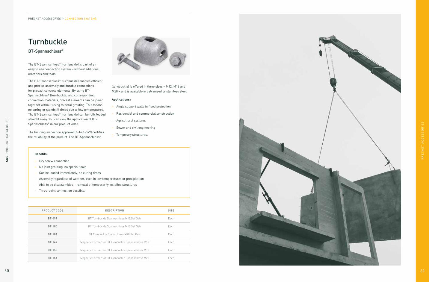
The BT-Spannschloss® (turnbuckle) is part of an
easy to use connection system – without additional
materials and tools.
The BT-Spannschloss® (turnbuckle) enables efficient
and precise assembly and durable connections
for precast concrete elements. By using BT-
Spannschloss® (turnbuckle) and corresponding
connection materials, precast elements can be joined
together without using mineral grouting. This means
no curing or standstill times due to low temperatures.
The BT-Spannschloss® (turnbuckle) can be fully loaded
straight away. You can view the application of BT-
Spannschloss® in our product video.
The building inspection approval (Z-14.4-599) certifies
the reliability of the product. The BT-Spannschloss®
(turnbuckle) is offered in three sizes – M12, M16 and
M20 – and is available in galvanised or stainless steel.
Applications:
– Angle support walls in flood protection
– Residential and commercial construction
– Agricultural systems
– Sewer and civil engineering
– Temporary structures.
PRODUCT CODE DESCRIPTION SIZE
BTI099 BT Turnbuckle Spannschloss M12 Set Galv Each
BTI100 BT Turnbuckle Spannschloss M16 Set Galv Each
BTI101 BT Turnbuckle Spannchloss M20 Set Galv Each
BTI149 Magnetic Former for BT Turnbuckle Spannschloss M12 Each
BTI150 Magnetic Former for BT Turnbuckle Spannschloss M16 Each
BTI151 Magnetic Former for BT Turnbuckle Spannschloss M20 Each
TurnbuckleBT-Spannschloss®
Benefits:
– Dry screw connection
– No joint grouting, no special tools
– Can be loaded immediately, no curing times
– Assembly regardless of weather, even in low temperatures or precipitation
– Able to be disassembled – removal of temporarily installed structures
– Three-point connection possible.
PRECAST ACCESSORIES > CONNECTION SYSTEMS

PR
EC
AS
T A
CC
ES
SO
RIE
S
63
SD
G P
RO
DU
CT
CA
TAL
OG
UE
62
Lifting Sockets Systems List of lifting sockets products 61
1. Design Method 74
1.1 Calculation assumptions 74
1.2 Drawing of the precast element and foreseen lifting method 74
1.3 Weight of the Element (P) 75
1.4 Formwork adhesion at the removal from the mould (A) 75
1.5 Position and determination of the number of efficient lifting points (n) 76
1.6 Sling angle and multiplication coefficient (Ce) 78
1.7 Lifting and handling dynamic coefficient (Ψdyn) 79
1.8 Resultant load by lifting point (F) 80
1.9 Concrete strength (fck) 80
2. Lifting Sockets 81
2.1 Tubular Socket: Lifting Socket with Cross Hole 82
2.2 Flat End Lifting Socket 85
2.3 Lifting Socket with Straight Rebar 86
2.4 Wavy Tail Lifting Anchor: Lifting Socket with Short Wavy Tail 88
2.5 Wavy Tail Lifting Anchor: Lifting Socket with Long Wavy Tail 90
2.6 Flat Plate Socket 92
2.7 Crown Foot Anchor 95
2.8 Crown Foot Anchor Bolt Type 97
2.9 Lifting Socket with Foot 99
3. Lifting Loop and Swivel Eye 101
3.1 Lifting Loop 102
3.1.1 Lifting Loop 102
3.1.2 Articulated Lifting Loop 103
3.1.3 Lateral Lifting Loop 104
3.1.4 Periodic control of the Lifting Loops 106
3.1.5 Usage and safety conditions of the Lifting Loops 106
3.2 Swivel Eye 108
3.3 Swivel Eye 109
3.3.1 Periodic control of the Swivel Eyes 109
3.3.2 Usage and safety conditions of the Swivel Eyes 110
4. Cast in Loops 111
4.1 Steel Wire Concrete Loops 111
4.2 Polypropylene Wire Cable Concrete Loops 114
5. Fixing Sockets 115
5.1 Tightening Torque 116
5.2 Flat End Fixing Socket 117
5.3 Flat End Fixing Socket with Nailing Plate 119
5.4 Bended fixing socket 120
5.5 Bent Fixing Socket with Nailing Plate 121
5.6 Waved Fixing Socket 122
5.7 Fixing Socket with Crosspin 123
5.8 Fixing Socket with Plate 124
5.9 Solid Rod Fixing Socket with Crosspin 125
5.10 Fixing Socket 126
6. Holding Device 127
6.1 Plastic Nailing Plate 127
6.2 Fixing Stud 128
6.3 Magnetic Nailing Plate 129
7. Cap 130
7.1 Sealing Cap 130
7.2 Data Clip 131
7.3 Data Clip with Ears 132
SAFE WORKING LOAD 0.5T 1.2T 2.0T 2.5T 4.0T 6.3T 8.0T
TUBULAR LIFTING SOCKET
RD 12MM
RD 16MM
RD 20MM
RD 24MM
RD 30MM
RD 36MM
RD 42MM
D (MM) 15 21 27 31 39.5 47 54
H (MM) 40 54 69 78 103 125 145
F (MM) 8 13 15.5 18 22.5 27.5 32
E (MM) 22 27 35 43 56 68 80
The lifting sockets are provided electro zinc plated.
SAFE WORKING LOAD 0.5T 1.2T 2.0T 2.5T 4.0T
STAINLESS STEEL TUBULAR SOCKET
RD 121MM
RD 161MM
RD 201MM
RD 241MM
RD 301MM
D (MM) 15 21 27 31 39.5
H (MM) 40 54 59 78 103
F (MM) 8 13 15.5 18 22.5
E (MM) 22 27 35 43 56
LIFTING SOCKETS SYSTEMS

PR
EC
AS
T A
CC
ES
SO
RIE
S
SD
G P
RO
DU
CT
CA
TAL
OG
UE
64 65
SAFE WORKING LOAD 0.5T 1.2T 2.0T 2.5T 4.0T 6.3T
STRAIGHT REBAR ANCHOR
RD 12x190
RD 16x250
RD 20x350
RD 24x400
RD 30x500
RD 36x650
D (MM) 15 21 27 31 39.5 47
H (MM) 190 250 350 400 500 650
HA (MM) 10 12 16 16 20 25
E (MM) 22 27 35 43 56 68
The lifting sockets are provided electro zinc plated, the rebar is black.
SAFE WORKING LOAD 0.5T 1.2T 2.0T 2.5T 4.0T
LIFTING INSERT RD
12MMRD
16MMRD
20MMRD
24MMRD
30MM
D (MM) 15 21 27 31 39.5
H (MM) 60 80 95 100 135
F (MM) 10 13 15 18 22.5
E (MM) 22 27 35 43 56
The lifting sockets are provided electro zinc plated.
PRECAST ACCESSORIES > LIFTING SOCKETS SYSTEMS
SAFE WORKING LOAD 0.5T 1.2T 2.0T 2.5T 4.0T 6.3T 8.0T
WAVY TAIL ANCHOR 12x108 16x167 20x187 24x250 30x300 36x380 42x450
D (MM) 15 21 27 31 39.5 47 54
H (MM) 108 167 187 250 300 380 450
HA (MM) 8 12 16 16 20 25 28
E (MM) 22 27 35 43 56 68 80
12x137 16x216 20x257 24x360 30x450 36x570
D (MM) 15 21 27 31 39.5 47
H (MM) 137 216 257 360 450 570
HA (MM) 10 12 16 16 20 25
E (MM) 22 27 35 43 56 68
SAFE WORKING LOAD 0.5T 1.2T 2.0T 2.5T 4.0T
FLAT PLATE SOCKET RD12 RD16 RD20 RD24 RD30
D (MM) 15 21 27 31 39.5
H (MM) 30 35 47 54 72
A (MM) 35 50 60 80 100
B (MM) 25 35 60 60 80
The lifting sockets are provided electro zinc plated.

PR
EC
AS
T A
CC
ES
SO
RIE
S
SD
G P
RO
DU
CT
CA
TAL
OG
UE
66 67
SAFE WORKING LOAD 0.5T 1.2T 2.0T 2.5T 4.0T 6.3T 8.0T
ARTICULATED LIFTING LOOP
RD/M12
RD/M16
RD/M20
RD/M24
RD/M30
RD/M36
RD/ M42
H (MM) 335 385 470 550 590 780 860
SAFE WORKING LOAD 0.5T 1.2T 2.0T 2.5T 4.0T 6.3T 8.0T
LIFTING LOOPRD/M12
RD/M16
RD/M20
RD/M24
RD/M30
RD/M36
RD/M42
A (MM) 6 8 10 11 14 16 20
C (MM) 155 155 215 255 303 340 425
E (MM) 22 27 35 43 56 68 80
SAFE WORKING LOAD 0.5T 1.2T
LIFTING SOCKET WITH FOOT
RD12060 RD16080
D (MM) 15 21
H (MM) 60 80
E (MM) 22 27
The lifting sockets are provided electro zinc plated, the foot is black.
PRECAST ACCESSORIES > LIFTING SOCKETS SYSTEMS
SAFE WORKING LOAD 0.5T 1.2T 2.0T 2.5T 4.0T 6.3T 8.0T
SWIVEL EYE 16MM 20MM 24MM 30MM 36MM 42MM
B (MM) 36 49.5 57 66 80 80
E (MM) 20 30 30 35 50 50
G (MM) 52 68 78 96.5 109 109
SAFE WORKING LOAD 0.8T 1.2T 1.6T 2.0T 2.5T 4.0T 5.2T 6.3T 10T
CAST IN LOOPS D (MM) 6 7 8 9 10 12 14 16 20
H (MM) 210 225 235 280 315 340 360 390 510
Other sizes on request.

PR
EC
AS
T A
CC
ES
SO
RIE
S
SD
G P
RO
DU
CT
CA
TAL
OG
UE
68 69
THREAD M6 M8 M10 M12 M16 M20 M24 M30
FLAT END FIXING SOCKET
6x35 MM
8x40 MM
10x45 MM
12x60 MM
16x70 MM
20x100 MM
24x120 MM
30x150 MM
Sockets provided electro zinc plated
H (MM) 35 40 45 60 70 100 120 150
G (MM) 6 8 8 10 12 14 14 17
E (MM) 8 8 10 12 16 20 24 30
A (MM) 11 15 12 23 20 40 40 65
8x50 MM
10x50 MM
12x70 MM
16x80 MM
20x120 MM
H (MM) 50 50 70 80 120
G (MM) 8 8 10 12 14
E (MM) 8 10 12 16 20
A (MM) 25 17 33 30 60
16x100 MM
H (MM) 100
G (MM) 12
E (MM) 16
A (MM) 50
PRECAST ACCESSORIES > LIFTING SOCKETS SYSTEMS
THREAD M6 M8 M10 M12 M16 M20
STAINLESS FLAT END FIXING SOCKET
6x35 MM
8x40 MM
10x451 MM
12x601 MM
16x801 MM
20x1001 MM
H (MM) 35 40 45 60 80 100
G (MM) 6 8 8 10 12 14
E (MM) 8 8 10 12 16 20
A (MM) 11 15 12 23 30 40
8x501 MM
10x501 MM
H (MM) 50 50
G (MM) 8 8
E (MM) 8 10
A (MM) 25 17
THREAD M6 M8 M10 M12 M16 M20 M24
FIXING SOCKET WITH NAILING PLATE
10x50C MM
12x70C MM
16x100C MM
20x100C MM
24x120C MM
H (MM) 50 70 100 100 120
G (MM) 8 10 12 14 14
E (MM) 10 12 16 20 24
A (MM) 20 30 32 40 50
D (MM) 40 40 50 60 60
Sockets provided electro zinc plated.

PR
EC
AS
T A
CC
ES
SO
RIE
S
SD
G P
RO
DU
CT
CA
TAL
OG
UE
70 71
THREAD M8 M10 M12 M16 M20
BENDED FIXING SOCKET8X30 MM
10X35 MM
12X45 MM
16X60 MM
20X100 MM
H(MM) 30 35 45 60 100
E(MM) 8 10 12 16 20
A(MM) 15 13 18 20 60
10X60 MM
12X70 MM
16X100 MM
H(MM) 60 70 100
E(MM) 10 12 16
A(MM) 35 40 60
Sockets provided electro zinc plated.
THREAD M6 M8 M10 M12 M16 M20 M24 M30
STAINLESS BENDED FIXING SOCKET
12x701 MM
16x1001 MM
H (MM) 70 100
E (MM) 12 16
A (MM) 40 60
PRECAST ACCESSORIES > LIFTING SOCKETS SYSTEMS
THREAD M10 M12 M16
BENDED FIXING SOCKET WITH NAILING PLATE
10X60C MM
12X70C MM
16X100C MM
H (MM) 60 70 100
E (MM) 10 12 16
A (MM) 35 40 60
D (MM) 40 40 50
Sockets provided electro zinc plated.

PR
EC
AS
T A
CC
ES
SO
RIE
S
SD
G P
RO
DU
CT
CA
TAL
OG
UE
72 73
THREAD M8 M10
WAVED FIXING SOCKET 8x40MM 10x40MM
H (MM) 40 40
E (MM) 10 10
A (MM) 15 15
10x60MM
H (MM) 60
E (MM) 10
A (MM) 30
Sockets provided electro zinc plated.
THREAD M16
FIXING SOCKET WITH CROSSPIN
16x70MM
H (MM) 70
E (MM) 16
A (MM) 26
AXE
D (MM) 10
I (MM) 50
Sockets provided electro zinc plated.
PRECAST ACCESSORIES > LIFTING SOCKETS SYSTEMS
FIXING SOCKET WITH PLATE
16x45MM
H (MM) 45
E (MM) 16
A (MM) 42
P (MM) 50
Sockets provided electro zinc plated.
THREAD M10M/
RD12M/
RD16M/
RD20M/
RD24M/
RD30M/
RD36M/
RD42
PLASTIC NAILING PLATE REF 10MM 12MM 16MM 20MM 24MM 30MM 36MM 42MM
D(MM) 40 40 55 55 55 70 70 96
MAGNETIC NAILING PLATE 12MM 16MM 20MM 24MM 30MM
D(MM) 65 65 65 65 65
PR
EC
AS
T A
CC
ES
SO
RIE
S
SD
G P
RO
DU
CT
CA
TAL
OG
UE
74 75
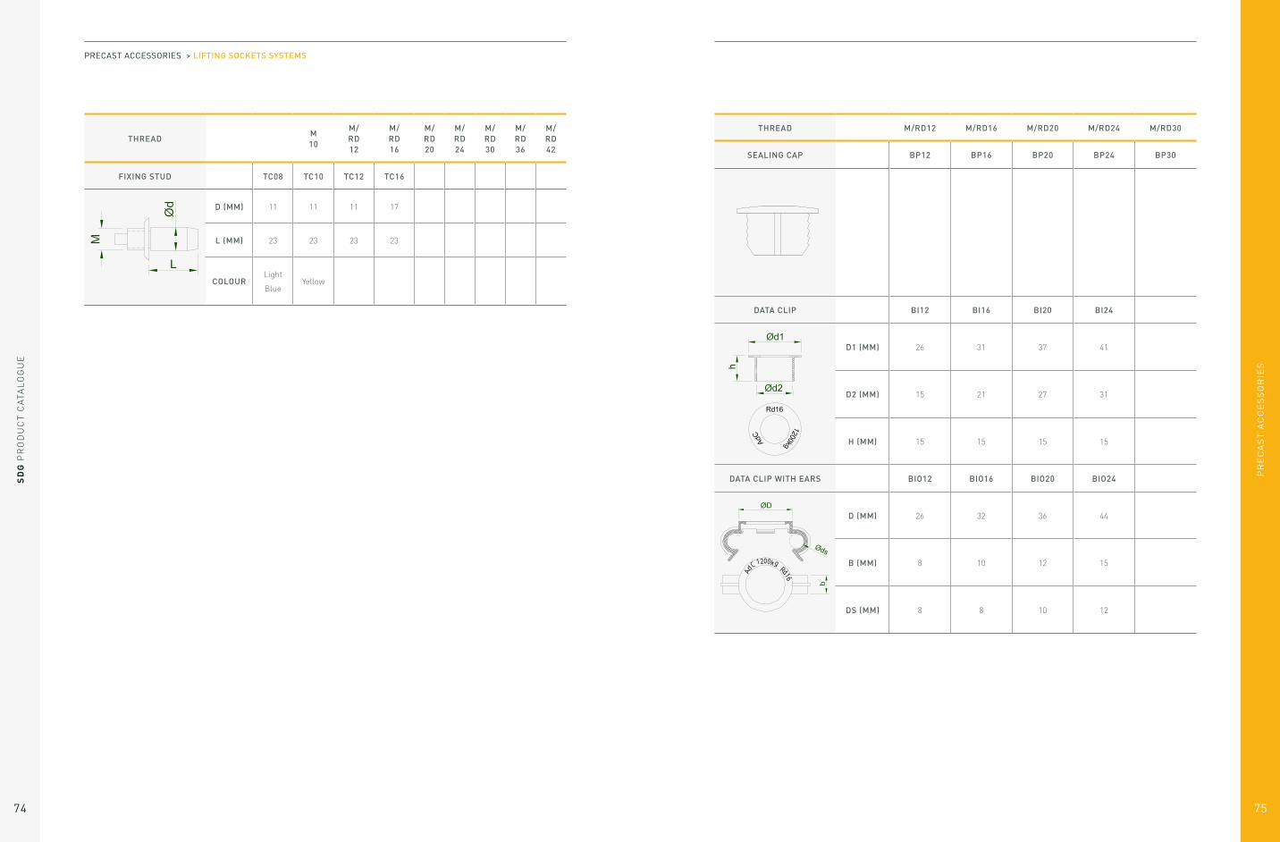
THREADM 10
M/ RD 12
M/ RD 16
M/RD 20
M/RD 24
M/RD 30
M/RD 36
M/RD 42
FIXING STUD TC08 TC10 TC12 TC16
D (MM) 11 11 11 17
L (MM) 23 23 23 23
COLOURLight
Blue Yellow
PRECAST ACCESSORIES > LIFTING SOCKETS SYSTEMS
THREAD M/RD12 M/RD16 M/RD20 M/RD24 M/RD30
SEALING CAP BP12 BP16 BP20 BP24 BP30
DATA CLIP BI12 BI16 BI20 BI24
D1 (MM) 26 31 37 41
D2 (MM) 15 21 27 31
H (MM) 15 15 15 15
DATA CLIP WITH EARS BIO12 BIO16 BIO20 BIO24
D (MM) 26 32 36 44
B (MM) 8 10 12 15
DS (MM) 8 8 10 12

PR
EC
AS
T A
CC
ES
SO
RIE
S
77
SD
G P
RO
DU
CT
CA
TAL
OG
UE
76
1. Design MethodThe aim of this design method is to evaluate the load on cemented sockets of a reinforced precast concrete element in order to select the appropriate socket.
This method is based on the most common applications.
If you have any doubt on the application, the
assumptions or any point mentioned in this document,
you should contact SDG Precast Technical Department.
It is also essential that the assumptions are clearly
communicated to the companies in charge of the
handling and lifting operations, in order to ensure
that the assumptions are corresponding to the actual
handling and lifting conditions.
In order to define the force on the lifting sockets, all
the following points have to be taken into account:
– The technical drawing of the precast element and
the kinetics of handling
– The weight of the element (and of the formwork and
other accessories lifted with the element)
– The formwork adhesion at the removal from
the mould
– The number of efficient lifting points (and not the
number of actual lifting points)
– The sling angle
– The dynamic coefficient (lifting machinery)
To define the correct anchor to use (type, length, size)
it is also necessary to know:
– The concrete strength when the element is lifted
It is also necessary to distinguish between the handling
of the element in the precast factory and on the
construction site. All the calculations have to be done
for both cases.
All these points are detailed in the following
paragraphs.
At first, the technical drawing of the element has to
be considered, then the means by which it is to be
handled. It is necessary to distinguish between the
handling in the precast factory and on site.
1.1 Calculation assumptions
1.2 Drawing of the precast element and foreseen lifting methodThe adhesion force is:
A = qadh x S
This adhesion force must be added to the weight of the
element in order to calculate the force required to lift it.
In some cases, the adhesion force can be zero if the
concrete is not in contact with the mould (pre-stressed
beam for example).
The actual weight of the element must be considered.
It includes in particular:
– The weight of the concrete element (volume x
density). The reinforced concrete density is equal
to 2500 daN/m3 (or 25 kN/m3) in general.
– The weight of the formwork and accessories
lifted with the element.
The adhesion will depend on 2 factors:
– The surface area of the element in contact with
the formwork (S in m²). All the surfaces in contact
with the formwork need to be considered, included
inclined surfaces.
– The surface condition of the mould. This surface
condition is defined by an adhesion factor (qadh in
daN/m²)
This force is to be considered at the removal of the
element from the mould.
1.3 Weight of the Element (P)
1.4 Formwork adhesion at the removal from the mould (A)
Type of mould Adhesion factor qadh
Oiled steel mould, Plywood coated with oiled plastic 100 daN/m²
Varnished oiled wooden mould 200 daN/m²
Oiled rough wooden mould 300 daN/m²
Polyurethane matrix Consult the matrix supplier
LIFTING SOCKETS SYSTEMS: DESIGN METHOD

PR
EC
AS
T A
CC
ES
SO
RIE
S
SD
G P
RO
DU
CT
CA
TAL
OG
UE
78 79
Set up the lifting points symmetrically to the center of gravity.
Here are some examples of lifting point positions:
In the case of asymmetric loads relative to the centre
of gravity, traction efforts must be calculated for each
lifting point taking into account distances to the centre
of gravity.
1.5 Position and determination of the number of efficient lifting points (n)
SLAB
PANEL
ROTATION PIECE
BEAM
PIPE
F1 = F x F2 = F xB
A + BA
A + B
Example for a beam:
PRECAST ACCESSORIES > LIFTING SOCKETS SYSTEMS > DESIGN METHOD
Balanced system
Apparent lifting points = 4
Efficient lifting points = 4
Unbalanced System
Apparent lifting points = 4
Efficient lifting points = 2
Depending on the type of socket that will be chosen
(see §2), the position of some lifting points may not be
suitable. It is essential to take into account in particular
the minimum distances between lifting points, and the
minimum distances at the concrete edge. A minimum
coating may also be required.
Based on the number of apparent lifting points and the
use or not of a balanced lifting system (such as a lifting
beam), the number of efficient lifting points is defined
as follows:
APPARENT LIFTING POINTSEFFICIENT LIFTING POINTS NUMBER (N)
WITH A BALANCED SYSTEM OTHERS LIFTING MEANS
4 4 2
3 3 2
2 2 2
Some examples:

PR
EC
AS
T A
CC
ES
SO
RIE
S
SD
G P
RO
DU
CT
CA
TAL
OG
UE
80 81
A multiplication coefficient Ce is generated by vertical forces (weight) on the slings.
For the calculation, angle β is to be considered as the angle between the vertical and the most inclined sling.
1.6 Sling angle and multiplication coefficient (Ce)
SLAB
BEAM
ROTATION PIECE
PIPE
β 0 15° 22,5° 30° 45° 60°
α = 2β 0 30° 45° 60° 90° 120°
Ce 1 1,035 1,082 1,155 1,414 2
L - 2 D 1,3 D D 0,7 D 0,6 D
PRECAST ACCESSORIES > LIFTING SOCKETS SYSTEMS > DESIGN METHOD
The values given in the table below are derived from the” Design and use of inserts for lifting and handling of
precast concrete - Elements”, CEN/TR 15728:2008.
The foreseen lifting system and the estimated values must be notified to the users (factory and site).
Dynamic coefficient required by type of element:
1.7 Lifting and handling dynamic coefficient (Ψdyn)
Ce = =1
cos (β)1
cos ( a ) 2
Other angle:
β = angle between the vertical and the most inclined sling.
It is necessary to consider the worst-case scenario with the largest angle β.
LIFTING AND HANDLING MACHINE DYNAMIC COEFFICIENT ΨDYN
Tower crane, overhead crane and portal crane 1,2
Mobile crane 1,4
Lifting and moving on flat terrain 2-2,5
Lifting and moving on rough terrain 3-4
TYPE OF ELEMENT DYNAMIC COEFFICIENT ΨDYN
Pipe and sewer 2
Frame below 12T 1,6
Frame between 12 and 20T 1,4
Frame above 20T 1,2
Wall 1,4
Beam below 12T 1,6
Beam between 12 and 20T 1,4
Beam above 20T 1,2

SD
G P
RO
DU
CT
CA
TAL
OG
UE
82
PR
EC
AS
T A
CC
ES
SO
RIE
S
83
The resultant load for each lifting point is equal to:
The concrete strength has to be determined:
– When lifting the element from the mould in the Precast factory
– When transporting and installing on site
The minimum allowed resistance of the concrete is 10 MPa.
NOTE: Sockets used more than 10 times, must not to be subject to a force more than 0.6 times their safety
working load (SWL). It is necessary to check in this case that F < 0.6* SWL (Anchor).
This calculation must be done for the lifting activity in
the precast factory, on site, and for any other handling
activity of the precast element.
1.8 Resultant load by lifting point (F)
1.9 Concrete strength (fck)
F =(P + A) x Ce x Ψdyn
n
PRECAST ACCESSORIES > LIFTING SOCKETS SYSTEMS > DESIGN METHOD
2. Lifting Sockets
This choice can be made according to the resultant load values by lifting point at the factory (Fu), and on site (Fc), and from the concrete strength during the first lifting at the precast factory and on site. The worst calculation (worst case scenario) should be used to ensure the socket is suitable for all uses.
If you have any doubt about your calculation, you should
contact SDG Technical Department.
The socket load capacity must be at least equal to the
highest calculated load value (Fu and Fc).
Various socket types are available, and the choice of type
of socket to be used is made according to each individual
set up.
Be careful during installation of the socket: Never weld
the socket.
There are different types of lifting sockets:
Tubular Socket: Socket with Cross Hole
Flat Plate Socket
Wavy Tail Anchor: Socket with waved rebar
Crown Foot Anchor
Lifting Socket
Lifting socket with foot
Socket with straight rebar
Crownfoot Anchor Bolt Type: Lifting Socket with Bolt
LIFTING SOCKETS SYSTEMS: LIFTING SOCKETS

PR
EC
AS
T A
CC
ES
SO
RIE
S
SD
G P
RO
DU
CT
CA
TAL
OG
UE
84 85
2.1 Tubular Socket: Lifting Socket with Cross Hole
REFERENCETHREAD
RD
SAFE WORKING LOAD [KG] DIMENSIONS [MM]WEIGHT
[KG]0°-45° 45° - 90° ØD H E ØF
DT 12 12 500 250 15 40 22 8 0,025
DT 16 16 1200 600 21 54 27 13 0,070
DT 20 20 2000 1000 27 69 35 15,5 0,155
DT 24 24 2500 1250 31 78 43 18 0,206
DT 30 30 4000 2000 39,5 103 56 22,5 0,450
DT 36 36 6300 3150 47 125 68 27,5 0,725
DT 42 42 8000 4000 54 145 80 32 1,100
DT 52 52 12500 6250 67 195 100 40 2,255
Sockets are provided electro zinc plated. They can also be made in stainless steel.
PRECAST ACCESSORIES > LIFTING SOCKETS SYSTEMS > LIFTING SOCKETS
A bent reinforced ribbed steel has to be put into the hole of the lifting socket.
Total length of the reinforced ribbed steel, depending of the concrete strength
REFERENCEØ HA
B500B [MM]
BENDING ROLL
ØB
CONCRETE STRENGTH (MPA)
10 15 20 25 30 35 40 45
DT 12 6 60 510 430 380 340 310 290 270 250
DT 16 10 100 760 640 560 510 470 430 410 390
DT 20 12 120 1020 850 750 670 610 570 530 500
DT 24 14 140 1110 940 820 740 680 630 590 560
DT 30 16 160 1490 1250 1080 970 880 820 760 720
DT 36 20 200 1870 1560 1360 1220 1110 1030 960 900
DT 42 25 250 1980 1670 1460 1320 1210 1120 1050 1000
DT 52 28 280 2640 2210 1920 1720 1560 1440 1350 1270
Minimum edge distances have to be respected.
REFERENCETHICKNESS MINI E [MM]
A MINI [MM]
B MINI [MM]
DT 12 60 150 300
DT 16 80 200 400
DT 20 100 275 550
DT 24 120 300 600
DT 30 140 350 650
DT 36 200 400 800
DT 42 240 500 1000
DT 52 275 600 1200

PR
EC
AS
T A
CC
ES
SO
RIE
S
SD
G P
RO
DU
CT
CA
TAL
OG
UE
86 87
In case of an inclined tension b≥ 15°, an additional stirrup has to be added.
Dimension of the additional shear pull stirrup
SOCKETØ HA
B500B[MM]
LENGTH OF THE
STIRRUP L [MM]
BENDING ROLL ØB
[MM]
RD 12 6 150 24
RD 16 8 200 32
RD 20 8 300 32
RD 24 10 300 40
RD 30 12 400 48
RD 36 14 550 56
RD 42 16 600 64
RD 52 20 750 140
In case of a transversal pull (till up) with an inclination ≥ 15°, additional reinforcements have to be added.
Dimension of the additional transversal pull reinforced ribbed steel
REBAR 1 REBAR 2
SOCKETØ
HA1 (MM)
L1 (MM)
H (MM)
Ø HA2 (MM)
L2 (MM)
RD 12 6 270 35 8 280
RD 16 8 420 49 12 400
RD 20 10 490 64 14 490
RD 24 12 520 75 14 550
RD 30 12 570 92 16 580
RD 36 14 690 118 16 700
RD 42 16 830 143 20 850
RD 52 20 930 174 20 1000
The rebar HA1 can be fixed to the socket
with the data clips with ears (see §7.3)
PRECAST ACCESSORIES > LIFTING SOCKETS SYSTEMS > LIFTING SOCKETS
2.2 Flat End Lifting Socket
Sockets are provided electro zinc plated.
The reinforced ribbed steel are the same than for the lifting socket with cross hole (see § 2.1):
– bent reinforced ribbed steel must be put into the hole of the lifting socket
– additional shear pull stirrup, In case of an inclined tension b ≥ 15°
– additional transversal pull reinforced ribbed steels, in case of a transversal pull (till up)
with an inclination ≥ ≥ 15°.
REFERENCETHREAD
RD
SAFE WORKING LOAD [KG] DIMENSIONS [MM]WEIGHT
[KG]0°- 45° 45° - 90° ØD H E ØF
DTP 12 12 500 250 15 60 22 10 0,031
DTP 16 16 1200 600 21 80 27 13 0,110
DTP 20 20 2000 1000 27 95 35 15 0,200
DTP 24 24 2500 1250 31 100 43 18 0,270
DTP 30 30 4000 2000 39,5 135 56 22,5 0,600

PR
EC
AS
T A
CC
ES
SO
RIE
S
SD
G P
RO
DU
CT
CA
TAL
OG
UE
88 89
2.3 Lifting Socket with Straight Rebar
REFERENCETHREAD
RD
SAFE WORKING LOAD [KG] DIMENSIONS [MM]WEIGHT
[KG]0°-45° 45° - 90° ØD H E ØF
DA 12 190 12 500 250 15 190 22 10 0,102
DA 16 250 16 1200 600 21 250 27 12 0,280
DA 16 270 16 1200 600 21 270 27 10 0,350
DA 20 350 20 2000 1000 27 350 35 16 0,540
DA 24 400 24 2500 1250 31 400 43 16 0,830
DA 24 720 24 2500 1250 31 720 43 16 1,225
DA 30 500 30 4000 2000 39,5 500 56 20 1,520
DA 36 650 36 6300 3150 47 650 68 25 3,120
DA 42 800 42 8000 4000 54 800 80 28 4,77
DA 52 900 52 12500 6250 67 900 100 32 7,30
Dimension of the lifting sockets with straight rebar
Sockets are provided electro zinc plated; rebar is black.
PRECAST ACCESSORIES > LIFTING SOCKETS SYSTEMS > LIFTING SOCKETS
REFERENCETHICKNESS MINI E [MM]
A MINI [MM]
B MINI [MM]
DA 12 190 60 150 300
DA 16 250 80 200 400
DA 16 270 80 200 400
DA 20 350 100 275 550
DA 24 400 120 300 600
DA 24 720 120 300 600
DA 30 500 140 350 650
DA 36 650 200 400 800
DA 42 800 240 500 1000
DA 52 900 275 600 1200
The Safe Working Load is given for a minimum concrete strength of 15 MPa
In case of an inclined tension b ≥ 15°, an additional stirrup has to be added.
Dimension of the additional shear pull stirrup
SOCKETØ HA
B500B[MM]
LENGTH OF THE
STIRRUP L [MM]
BENDING ROLL ØB
[MM]
RD 12 6 150 24
RD 16 8 200 32
RD 20 8 300 32
RD 24 10 300 40
RD 30 12 400 48
RD 36 14 550 56
RD 42 16 600 64
RD 52 20 750 140
In case of a transversal pull (till up) with an inclination ≥ 15°, additional reinforcements have to be added.
See § 2.1 for more information concerning the additional reinforcements.
PR
EC
AS
T A
CC
ES
SO
RIE
S
SD
G P
RO
DU
CT
CA
TAL
OG
UE
90 91
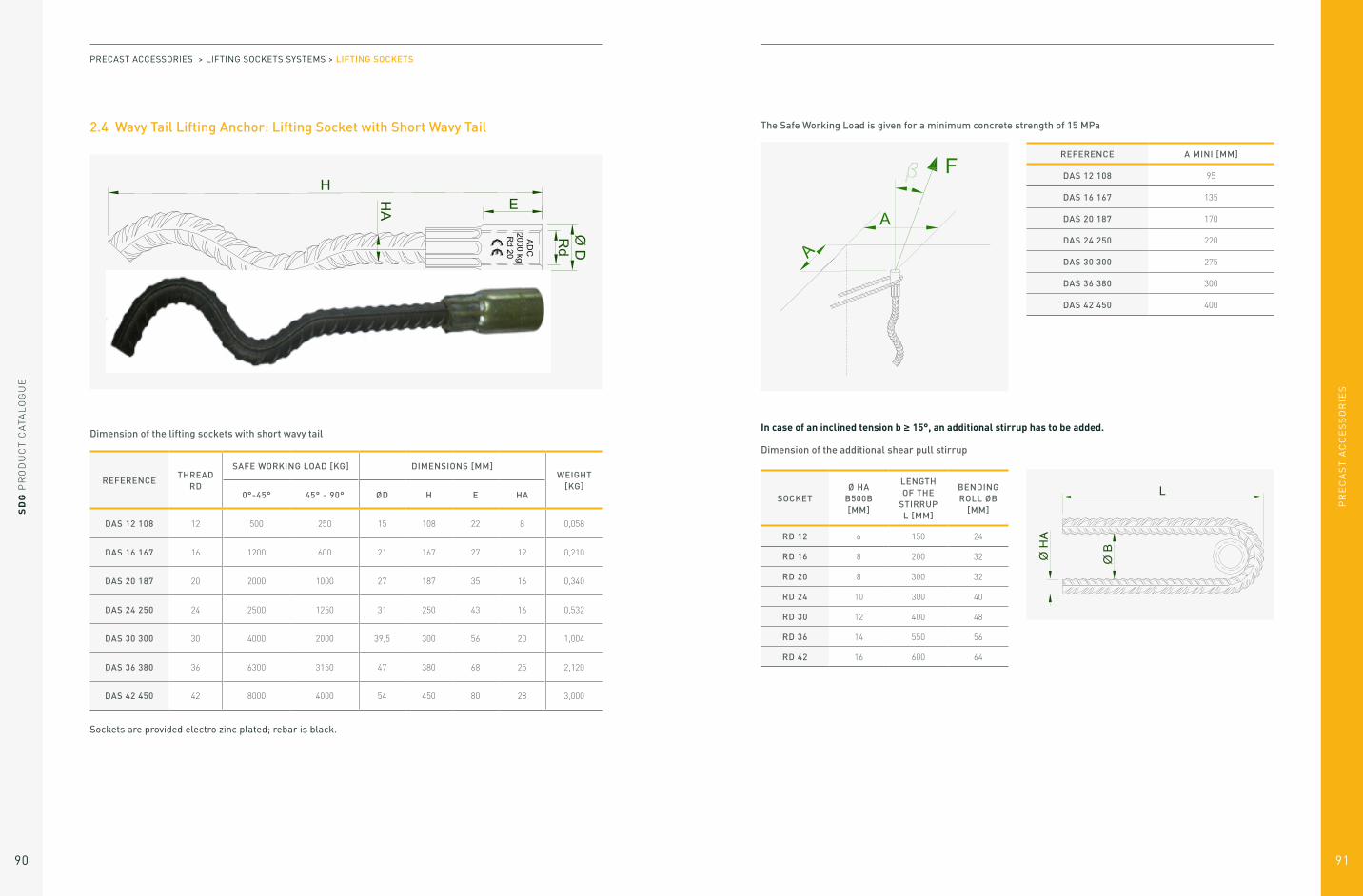
2.4 Wavy Tail Lifting Anchor: Lifting Socket with Short Wavy Tail
REFERENCETHREAD
RD
SAFE WORKING LOAD [KG] DIMENSIONS [MM]WEIGHT
[KG]0°-45° 45° - 90° ØD H E HA
DAS 12 108 12 500 250 15 108 22 8 0,058
DAS 16 167 16 1200 600 21 167 27 12 0,210
DAS 20 187 20 2000 1000 27 187 35 16 0,340
DAS 24 250 24 2500 1250 31 250 43 16 0,532
DAS 30 300 30 4000 2000 39,5 300 56 20 1,004
DAS 36 380 36 6300 3150 47 380 68 25 2,120
DAS 42 450 42 8000 4000 54 450 80 28 3,000
Dimension of the lifting sockets with short wavy tail
Sockets are provided electro zinc plated; rebar is black.
PRECAST ACCESSORIES > LIFTING SOCKETS SYSTEMS > LIFTING SOCKETS
REFERENCE A MINI [MM]
DAS 12 108 95
DAS 16 167 135
DAS 20 187 170
DAS 24 250 220
DAS 30 300 275
DAS 36 380 300
DAS 42 450 400
The Safe Working Load is given for a minimum concrete strength of 15 MPa
In case of an inclined tension b ≥ 15°, an additional stirrup has to be added.
Dimension of the additional shear pull stirrup
SOCKETØ HA
B500B[MM]
LENGTH OF THE
STIRRUP L [MM]
BENDING ROLL ØB
[MM]
RD 12 6 150 24
RD 16 8 200 32
RD 20 8 300 32
RD 24 10 300 40
RD 30 12 400 48
RD 36 14 550 56
RD 42 16 600 64

PR
EC
AS
T A
CC
ES
SO
RIE
S
SD
G P
RO
DU
CT
CA
TAL
OG
UE
92 93
2.5 Wavy Tail Lifting Anchor: Lifting socket with Long Wavy Tail
REFERENCETHREAD
RD
SAFE WORKING LOAD [KG] DIMENSIONS [MM]WEIGHT
[KG]0°-45° 45° - 90° ØD H E HA
DAS 12 137 12 500 250 15 137 22 10 0,076
DAS 12 300 12 500 250 15 300 22 8 0,151
DAS 16 216 16 1200 600 21 216 27 12 0,250
DAS 20 257 20 2000 1000 27 257 35 16 0,520
DAS 20 300 20 2000 1000 27 300 35 16 0,550
DAS 24 360 24 2500 1250 31 360 43 16 0,740
DAS 30 450 30 4000 2000 39,5 450 56 20 1,470
DAS 36 570 36 6300 3150 47 570 68 25 2,850
DAS 42 620 42 8000 4000 54 620 80 28 3,870
DAS 52 880 52 12500 6250 67 880 100 32 7,200
Dimension of the lifting sockets with long wavy tail
Sockets are provided electro zinc plated; rebar is black.
PRECAST ACCESSORIES > LIFTING SOCKETS SYSTEMS > LIFTING SOCKETS
The Safe Working Load is given for a minimum concrete strength of 15 MPa
In case of an inclined tension b ≥ 15°, an additional stirrup has to be added.
Dimension of the additional shear pull stirrup
SOCKETØ HA
B500B[MM]
LENGTH OF THE
STIRRUP L [MM]
BENDING ROLL ØB
[MM]
RD 12 6 150 24
RD 16 8 200 32
RD 20 8 300 32
RD 24 10 300 40
RD 30 12 400 48
RD 36 14 550 56
RD 42 16 600 64
RD 52 20 750 140
REFERENCETHICKNESS MINI E [MM]
A MINI [MM]
B MINI [MM]
DAS 12 137 60 150 300
DAS 12 300 60 150 300
DAS 16 216 80 200 400
DAS 20 257 100 275 550
DAS 20 300 100 275 550
DAS 24 360 120 300 600
DAS 30 450 140 350 650
DAS 36 570 200 400 800
DAS 42 620 240 500 1000
DAS 52 880 275 600 1200
In case of a transversal pull (till up) with an inclination ≥ 15°, additional reinforcements have to be added.
See § 2.1 for more information concerning the additional reinforcements.
PR
EC
AS
T A
CC
ES
SO
RIE
S
SD
G P
RO
DU
CT
CA
TAL
OG
UE
94 95
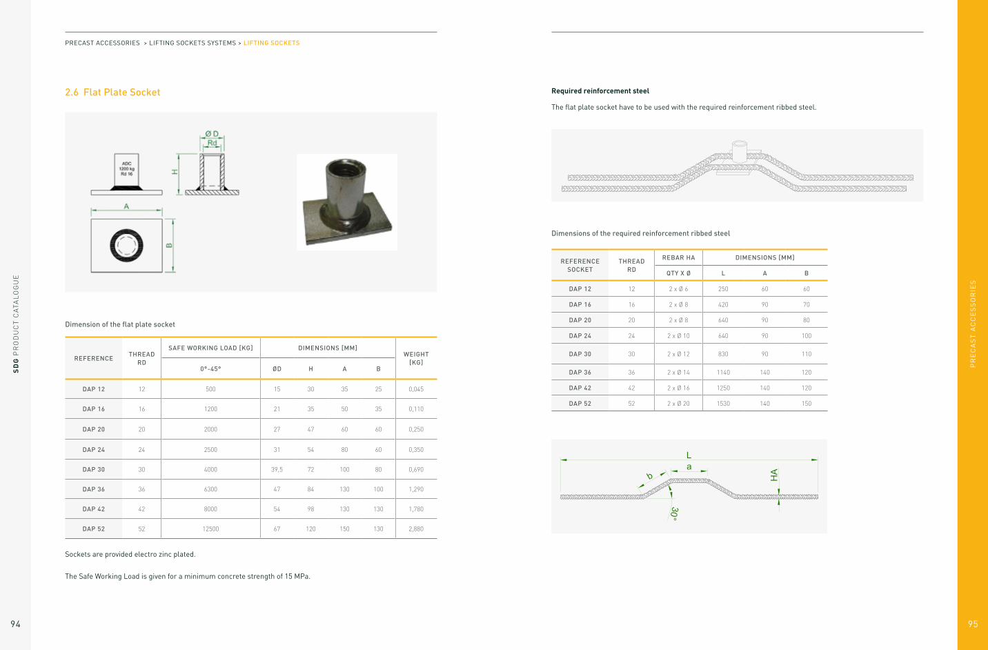
2.6 Flat Plate Socket
REFERENCETHREAD
RD
SAFE WORKING LOAD [KG] DIMENSIONS [MM]WEIGHT
[KG]0°-45° ØD H A B
DAP 12 12 500 15 30 35 25 0,045
DAP 16 16 1200 21 35 50 35 0,110
DAP 20 20 2000 27 47 60 60 0,250
DAP 24 24 2500 31 54 80 60 0,350
DAP 30 30 4000 39,5 72 100 80 0,690
DAP 36 36 6300 47 84 130 100 1,290
DAP 42 42 8000 54 98 130 130 1,780
DAP 52 52 12500 67 120 150 130 2,880
Dimension of the flat plate socket
Sockets are provided electro zinc plated.
The Safe Working Load is given for a minimum concrete strength of 15 MPa.
PRECAST ACCESSORIES > LIFTING SOCKETS SYSTEMS > LIFTING SOCKETS
Required reinforcement steel
The flat plate socket have to be used with the required reinforcement ribbed steel.
Dimensions of the required reinforcement ribbed steel
REFERENCE SOCKET
THREAD RD
REBAR HA DIMENSIONS [MM]
QTY X Ø L A B
DAP 12 12 2 x Ø 6 250 60 60
DAP 16 16 2 x Ø 8 420 90 70
DAP 20 20 2 x Ø 8 640 90 80
DAP 24 24 2 x Ø 10 640 90 100
DAP 30 30 2 x Ø 12 830 90 110
DAP 36 36 2 x Ø 14 1140 140 120
DAP 42 42 2 x Ø 16 1250 140 120
DAP 52 52 2 x Ø 20 1530 140 150

PR
EC
AS
T A
CC
ES
SO
RIE
S
SD
G P
RO
DU
CT
CA
TAL
OG
UE
96 97
Minimum edge distance and minimum distance between sockets
REFERENCE SOCKET
A MINI [MM]
B MINI [MM]
E MINI [MM]
DAP 12 180 350 75
DAP 16 250 500 85
DAP 20 300 600 100
DAP 24 400 800 115
DAP 30 500 1000 140
DAP 36 650 1300 160
DAP 42 650 1300 175
DAP 52 750 1500 215
In case of an inclined tension b ≥ 15°, an additional stirrup has to be added.
Dimension of the additional shear pull stirrup
SOCKETØ HA
B500B[MM]
LENGTH OF THE
STIRRUP L [MM]
BENDING ROLL ØB
[MM]
RD 12 6 150 24
RD 16 8 200 32
RD 20 8 300 32
RD 24 10 300 40
RD 30 12 400 48
RD 36 14 550 56
RD 42 16 600 64
RD 52 20 750 140
PRECAST ACCESSORIES > LIFTING SOCKETS SYSTEMS > LIFTING SOCKETS
2.7 Crown Foot Anchor
Dimensions of the lifting socket with machined foot
Sockets are provided electro zinc plated.
REFERENCETHREAD
RD
SAFE WORKING LOAD [KG] DIMENSIONS [MM]WEIGHT
[KG]0°-45° 45° - 90° ØD H E
DPU 12 060 12 500 250 17 60 22 0,06
DPU 16 080 16 1200 600 21 80 27 0,14
DPU 20 100 20 2000 1000 27 100 35 0,20
DPU 24 115 24 2500 1250 31 115 43 0,40
DPU 30 150 30 4000 2000 40 150 56 0,70

PR
EC
AS
T A
CC
ES
SO
RIE
S
SD
G P
RO
DU
CT
CA
TAL
OG
UE
98 99
The Safe Working Load is given for a minimum concrete strength of 15 MPa.
In case of an inclined tension b ≥ 15°, an additional stirrup has to be added.
Dimension of the additional shear pull stirrup
REFERENCEA MINI [MM]
B MINI [MM]
DPU 12 060 180 360
DPU 16 080 240 480
DPU 20 100 300 600
DPU 24 115 345 690
DPU 30 150 450 900
SOCKETØ HA
B500B[MM]
LENGTH OF THE
STIRRUP L [MM]
BENDING ROLL ØB
[MM]
RD 12 6 150 24
RD 16 8 200 32
RD 20 8 300 32
RD 24 10 300 40
RD 30 12 400 48
PRECAST ACCESSORIES > LIFTING SOCKETS SYSTEMS > LIFTING SOCKETS
2.8 Crown Foot Anchor Bolt Type
Dimensions of the lifting socket with bolt
Sockets are provided electro zinc plated.
REFERENCETHREAD
RD
SAFE WORKING LOAD [KG] DIMENSIONS [MM]WEIGHT
[KG]0°-45° 45° - 90° ØD H E
DP 12 060 12 500 250 15 60 22 0,060
DP 12 070 12 500 250 15 70 22 0,080
DP 16 080 16 1200 600 21 80 27 0,140
DP 20 100 20 2000 1000 27 100 35 0,200
DP 20 127 20 2000 1000 27 127 35 0,266
DP 24 140 24 2500 1250 31 140 43 0,440
DP 30 170 30 4000 2000 39,5 170 56 0,750

PR
EC
AS
T A
CC
ES
SO
RIE
S
SD
G P
RO
DU
CT
CA
TAL
OG
UE
100 101
The Safe Working Load is given for a minimum concrete strength of 15 MPa.
In case of an inclined tension b ≥ 15°, an additional stirrup has to be added.
Dimension of the additional shear pull stirrup
REFERENCEA MINI [MM]
B MINI [MM]
DP 12 060 180 360
DP 12 070 210 420
DP 16 080 240 480
DP 20 100 300 600
DP 20 127 380 760
DP 24 140 420 840
DP 30 170 510 1020
SOCKETØ HA
B500B[MM]
LENGTH OF THE
STIRRUP L [MM]
BENDING ROLL ØB
[MM]
RD 12 6 150 24
RD 16 8 200 32
RD 20 8 300 32
RD 24 10 300 40
RD 30 12 400 48
PRECAST ACCESSORIES > LIFTING SOCKETS SYSTEMS > LIFTING SOCKETS
2.9 Lifting Socket with Foot
Dimensions of the lifting socket with foot
Sockets are provided electro zinc plated.
Depending on the manufacture, the foot may be smooth steel or crenellated steel.
REFERENCETHREAD
RD
SAFE WORKING LOAD [KG] DIMENSIONS [MM]WEIGHT
[KG]0°-45° 45° - 90° ØD H E
DP 12 100 12 500 250 15 100 22 0,050
DP 12 150 12 500 250 15 150 22 0,074
DP 16 130 16 1200 600 21 130 27 0,160
DP 16 175 16 1200 600 21 175 27 0,160
DP 20 185 20 2000 1000 27 185 35 0,335
DP 20 250 20 2000 1000 27 250 35 0,410
DP 24 200 24 2500 1250 31 200 43 0,474
DP 24 250 24 2500 1250 31 250 43 0,550
DP 24 275 24 2500 1250 31 275 43 0,580
DP 30 275 30 4000 2000 39,5 275 56 0,923
DP 30 350 30 4000 2000 39,5 350 56 1,251
DP 36 335 36 6300 3150 47 335 68 1,860
DP 36 450 36 6300 3150 47 450 68 2,330

SD
G P
RO
DU
CT
CA
TAL
OG
UE
102
PR
EC
AS
T A
CC
ES
SO
RIE
S
103
The Safe Working Load is given for a minimum concrete strength of 15 MPa.
In case of an inclined tension b ≥ 15°, an additional stirrup has to be added.
Dimension of the additional shear pull stirrup
SOCKETØ HA
B500B[MM]
LENGTH OF THE
STIRRUP L [MM]
BENDING ROLL ØB
[MM]
RD 12 6 150 24
RD 16 8 200 32
RD 20 8 300 32
RD 24 10 300 40
RD 30 12 400 48
RD 36 14 550 56
REFERENCETHICKNESS MINI E [MM]
A MINI [MM]
B MINI [MM]
DP 12 100 120 150 300
DP 12 150 110 150 300
DP 16 130 220 200 400
DP 16 175 200 200 400
DP 20 185 240 300 600
DP 20 250 220 300 600
DP 24 200 260 350 700
DP 24 250 240 350 700
DP 24 275 240 350 700
DP 30 275 300 500 1000
DP 30 350 280 500 1000
DP 36 335 320 770 1540
DP 36 450 300 720 1440
In case of a transversal pull (till up) with an inclination ≥ 15°, additional reinforcements have to be added.
See § 2.1 for more information concerning the additional reinforcements.
PRECAST ACCESSORIES > LIFTING SOCKETS SYSTEMS > LIFTING SOCKETS
3. Lifting Loop and Swivel Eye
4 types of lifting loops and lifting eyes are proposed:
LIFTING LOOP
LATERAL LIFTING LOOP
ARTICULATED LIFTING LOOP
SWIVEL EYE
LIFTING SOCKETS SYSTEMS: LIFTING LOOP AND SWIVEL EYE

PR
EC
AS
T A
CC
ES
SO
RIE
S
SD
G P
RO
DU
CT
CA
TAL
OG
UE
104 105
3.1 Lifting Loop
3.1.1 Lifting Loop
REFERENCETHREAD
RD
SAFE WORKING LOAD [KG]
DIMENSIONS [MM]LABEL COLOR
0°- 45° H ØD E
EL 12 Rd 12 500 155 6 22 Orange
EL 16 Rd 16 1 200 165 8 28 Red
EL 20 Rd 20 2 000 215 10 36 Light green
EL 24 Rd 24 2 500 255 12 42 Dark grey
EL 30 Rd 30 4 000 300 16 54 Dark green
EL 36 Rd 36 6 300 360 18 65 Light blue
EL 42 Rd 42 8 000 425 20 72 Light grey
EL 52 Rd 52 12 500 555 26 90 Sulphur yellow
The lifting loops are supplied with a colored label. This label indicates :
– the manufacturer (ADC)
– the thread (example Rd24)
– the Safe Working Load (example 2500 kg)
On request, slings can also be provided in metric threading.
PRECAST ACCESSORIES > LIFTING SOCKETS SYSTEMS > LIFTING LOOP AND SWIVEL EYE
3.1 Lifting Loop
3.1.2 Articulated Lifting Loop
REFERENCETHREAD
RD
SAFE WORKING LOAD [KG]
DIMENSIONS [MM]LABEL COLOR
0°- 45° H ØD E
EL 12 Rd 12 500 335 8 22 Orange
EL 16 Rd 16 1 200 385 8 28 Red
EL 20 Rd 20 2 000 470 10 36 Light green
EL 24 Rd 24 2 500 550 12 42 Dark grey
EL 30 Rd 30 4 000 590 16 54 Dark green
EL 36 Rd 36 6 300 780 18 65 Light blue
EL 42 Rd 42 8 000 860 20 72 Light grey
EL 52 Rd 52 12 500 1080 26 70 Sulphur yellow
The lifting loops are supplied with a colored label. This label indicates :
– the manufacturer (ADC)
– the thread (example Rd24)
– the Safe Working Load (example 2500 kg)
On request, slings can also be provided in metric threading.

PR
EC
AS
T A
CC
ES
SO
RIE
S
SD
G P
RO
DU
CT
CA
TAL
OG
UE
106 107
3.1 Lifting Loop
3.1.3 Lateral Lifting Loop
Set consisting of a lateral lifting loop and a screw to lift on the sides an element of the type concrete tank.
LIFTING LOOP REFERENCE
FOR SCREW M/RD
SAFE WORKING LOAD [KG] DIMENSIONS [MM]
75°- 90° HIGHT Ø HOLE
ELL16 16 2 000 300 16.5
ELL24 24 4 000 330 24.5
ELL30 30 5 200 400 31.0
The Safe Working Load is given for a minimum concrete strength of 15 MPa.
PRECAST ACCESSORIES > LIFTING SOCKETS SYSTEMS > LIFTING LOOP AND SWIVEL EYE
SCREW REFERENCE
THREAD MLENGTH UNDER
HEAD [MM]CLASS
ALLEN SCREWS [MM]
10VI16040-88 M 16 40 8.8 24
10VI24050-88 M 24 50 8.8 36
10VI30070-88 M 30 70 8.8 46
The sockets should be positioned at a sufficient distance from the top of the element to prevent the concrete from
cracking above the socket. The sockets should be positioned at the level of the concrete. The use of a holding disc
that would cause the socket withdrawal is strictly prohibited.
USAGE AND SAFETY CONDITIONS
Do this:
– Make sure the screw is fully screwed into the socket
– Make sure the threading of the socket is clea.
– Ensure that the concrete strength is at least equal to that provided in the sizing of the anchors.
A concrete at 25 MPa is the bare minimum
– Make sure the loop is free of defects such as welding trace, cable wire breakage, excessive corrosion
– Make sure the screw thread is clean and undamaged.
Don’t do this:
– Never use the lateral lifting loop with an angle of tilt to the vertical above 15 degrees
– Never weld the lifting loop for any reason.
Hexagon Head Screw DIN 933

PR
EC
AS
T A
CC
ES
SO
RIE
S
SD
G P
RO
DU
CT
CA
TAL
OG
UE
108 109
3.1 Lifting Loop
3.1.4 Periodic control of the Lifting Loops
Whatever the frequency of use, each lifting loops must be controlled at least once a year by a competent person. Any physical abnormality, deformation, any sign of welding, must lead to the immediate destruction of the lifting loop.
The points to control are:
– Absence of permanent deformation
– Absence of crushing of the wire rope
– Absence of bends or twists of the wire rope
– Absence of damage due to corrosion
– Maximum 4 broken wires on a rope
The lifting loops cannot be repaired.
4.1.5 Usage and safety conditions of the Lifting Loops
BEFORE USE
To do:
– For lifting, always use sockets and lifting loops with
a round thread (Rd)
– Make sure that the thread diameter of the lifting
loop and that the Safe Working Load on the label of
the lifting loop are the same than for the socket
– Make sure than the thread of the lifting loop is fully
engaged into the thread of the socket
– Make sure that the thread of the socket is clean
– Make sure that the length of the slings is at least
twice the distance between the sockets, in order
to have an angle of 30° between the slings. It is
possible to have a bigger angle only if it has been
considered in calculations. It is always better to use
a lifting beam
– Make sure that the concrete strength is at least
equal to that used in the calculations. The minimum
concrete strength is 15 MPa
– Make sure that the lifting loop has no default, such
as welding points, broken wires on a rope, clean
thread without crushing.
Not to do:
– Never screw a round thread lifting loop (Rd) into
a metric thread socket (M). The lifting loop would
never be able to screw on a sufficient length, and
the load capacity will be dangerously reduced
– Never use the lifting loops with an angle of more than 45° from the axe of the socket
– You must not weld the socket nor the lifting loop,
for whatever reason
– Under no circumstances should the diameter of the
hook or shackle D, attached to the loop, be less than
3.5 times the diameter of the cable of the lifting
loop. If possible, we recommend a diameter greater
than 5 times the diameter of the cable.
PRECAST ACCESSORIES > LIFTING SOCKETS SYSTEMS > LIFTING LOOP AND SWIVEL EYE
IN USE
– When precast concrete elements are transported
by construction companies, they are subject to
shocks and impact loads. This factor increases the
load on the socket by several times the dead-weight
should be taken into account in load calculations.
Therefore, care should be taken in transporting the
elements on site
– When the sockets are used to lift a unit from a
mould, the adhesion between the freshly cast
concrete and the mould increase the forces on the
sockets. This element needs also to be taken into
consideration when calculating the required load.
MAINTENANCE
– All lifting loops must be controlled at least once a
year by a competent person. The lifting loops must
not show any sign of deformity
– The lifting loops cannot be repaired.
GENERAL
– The lifting loops must be used only for lifting
precast concrete elements
– Users of the lifting loops must be familiar with the
usage and safety instructions
– All usage and safety instructions must be respected
when lifting loops are used.
If you have any question, do not hesitate to contact SDG Technical Department.
PR
EC
AS
T A
CC
ES
SO
RIE
S
SD
G P
RO
DU
CT
CA
TAL
OG
UE
110 111
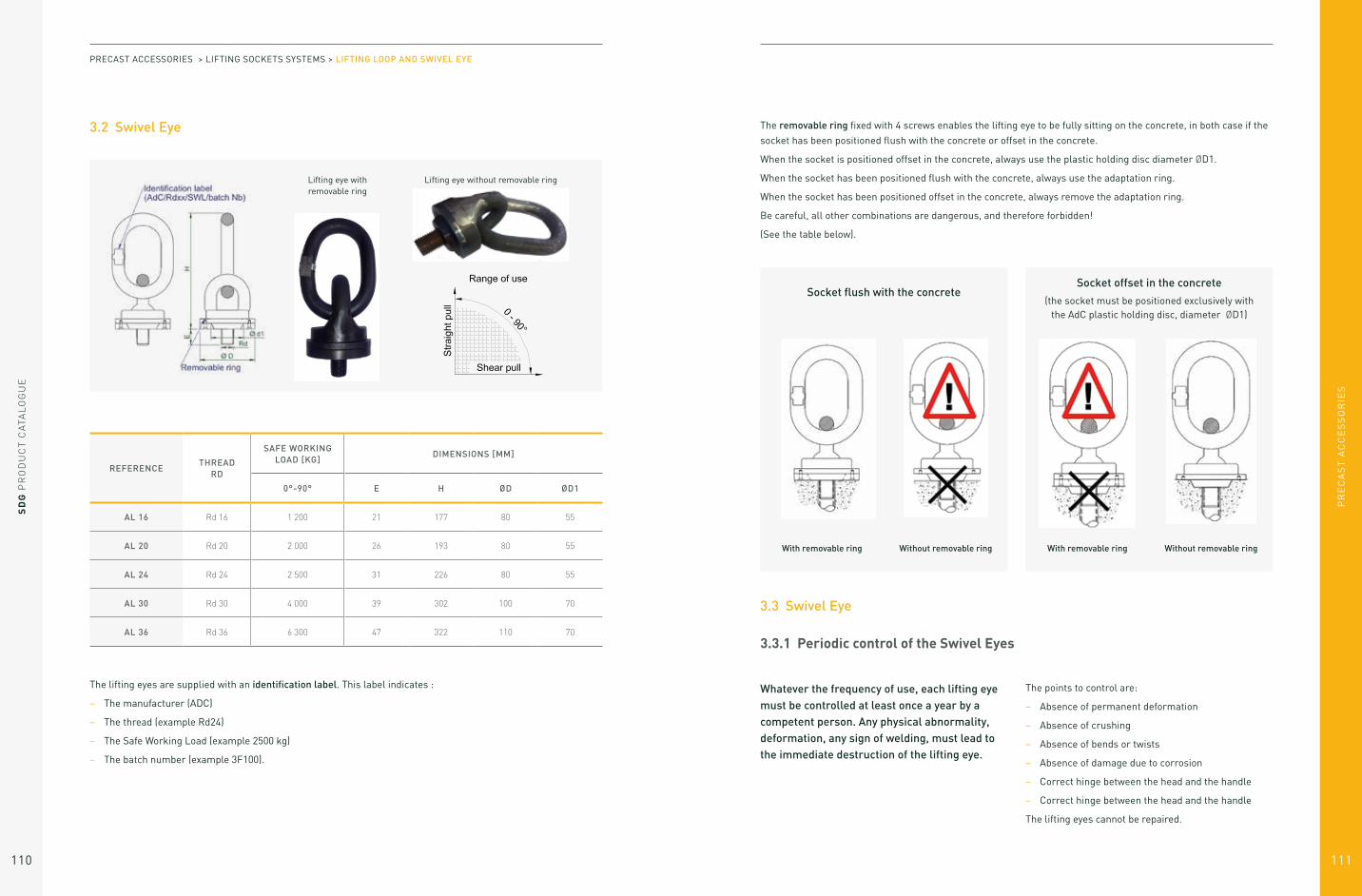
3.2 Swivel Eye
Lifting eye with removable ring
Lifting eye without removable ring
REFERENCETHREAD
RD
SAFE WORKING LOAD [KG]
DIMENSIONS [MM]
0°-90° E H ØD ØD1
AL 16 Rd 16 1 200 21 177 80 55
AL 20 Rd 20 2 000 26 193 80 55
AL 24 Rd 24 2 500 31 226 80 55
AL 30 Rd 30 4 000 39 302 100 70
AL 36 Rd 36 6 300 47 322 110 70
The lifting eyes are supplied with an identification label. This label indicates :
– The manufacturer (ADC)
– The thread (example Rd24)
– The Safe Working Load (example 2500 kg)
– The batch number (example 3F100).
PRECAST ACCESSORIES > LIFTING SOCKETS SYSTEMS > LIFTING LOOP AND SWIVEL EYE
The removable ring fixed with 4 screws enables the lifting eye to be fully sitting on the concrete, in both case if the
socket has been positioned flush with the concrete or offset in the concrete.
When the socket is positioned offset in the concrete, always use the plastic holding disc diameter ØD1.
When the socket has been positioned flush with the concrete, always use the adaptation ring.
When the socket has been positioned offset in the concrete, always remove the adaptation ring.
Be careful, all other combinations are dangerous, and therefore forbidden!
(See the table below).
Socket flush with the concreteSocket offset in the concrete
(the socket must be positioned exclusively with the AdC plastic holding disc, diameter ØD1)
With removable ring Without removable ring Without removable ringWith removable ring
3.3 Swivel Eye
3.3.1 Periodic control of the Swivel Eyes
Whatever the frequency of use, each lifting eye must be controlled at least once a year by a competent person. Any physical abnormality, deformation, any sign of welding, must lead to the immediate destruction of the lifting eye.
The points to control are:
– Absence of permanent deformation
– Absence of crushing
– Absence of bends or twists
– Absence of damage due to corrosion
– Correct hinge between the head and the handle
– Correct hinge between the head and the handle
The lifting eyes cannot be repaired.

SD
G P
RO
DU
CT
CA
TAL
OG
UE
112
PR
EC
AS
T A
CC
ES
SO
RIE
S
113
To do:
– For lifting, always use sockets and lifting eyes with a round thread (Rd)
– Make sure that the thread diameter of the lifting eye and that the Safe Working Load on the label of the lifting eye are the same than for the socket
– Make sure than the thread of the lifting eye is fully engaged into the thread of the socket. If the lifting eye is not enough engaged onto the socket, it reduces its load capacity.
– Make sure that the thread of the socket is clean.
– Make sure that the bottom surface of the lifting eye is fully sitting on the concrete:- If the socket has been positioned flush with the
concrete, use the adaptation ring- If the socket has been positioned offset in the
concrete with a recess holding disc diameter ØD1, remove the adaptation ring
– Make sure that the length of the slings is at least twice the distance between the sockets, in order to have an angle of 30° between the slings. It is possible to have a bigger angle only if it has been considered in calculations. It is always better to use a lifting beam
– Make sure that the concrete strength is at least equal to that used in the calculations. The minimum concrete strength is 15 MPa
– Make sure that the lifting eye has no default, such as welding points and clean thread without crushing.
Not to do:
– Never screw a round thread lifting eye (Rd) into a metric thread socket (M). The lifting eye would never be able to screw on a sufficient length, and the load capacity will be dangerously reduced
– You must not weld the socket nor the lifting eyes,
for whatever reason.
IN USE
– When precast concrete elements are transported
by construction companies, they are subject to
shocks and impact loads. This factor increases the
load on the socket by several times the dead-weight
should be taken into account in load calculations.
Therefore, care should be taken in transporting the
elements on site
– When the sockets are used to lift a unit from a
mould, the adhesion between the freshly cast
concrete and the mould increase the forces on the
sockets. This element needs also to be taken into
consideration when calculating the required load.
MAINTENANCE
– All lifting eyes must be controlled at least once a
year by a competent person. The lifting eyes must
not show any sign of deformity
– The lifting eyes cannot be repaired.
GENERAL
– The lifting eyes must be used only for lifting precast
concrete elements
– Users of the lifting eyes must be familiar with the
usage and safety instructions
– All usage and safety instructions must be respected
when lifting eyes are used.
If you have any question, do not hesitate to contact SDG Technical Department.
3.3 Swivel Eye
3.3.2 Usage and safety conditions of the Swivel Eyes
BEFORE USE
PRECAST ACCESSORIES > LIFTING SOCKETS SYSTEMS > LIFTING LOOP AND SWIVEL EYE
4. Cast in Loops
4.1 Steel Wire Concrete Loops
REFERENCE
SAFE WORKING LOAD [KG]
DIMENSIONS [MM]LABEL COLOR
WEIGHT[KG]
0°- 30° ØD H F E
BL 08 800 6 210 55 155 Pur white 0,085
BL 12 1200 7 225 60 165 Red 0,108
BL 12/400 1200 7 400 60 165 Red 0,120
BL 16 1600 8 235 60 175 Light Pink 0,143
BL 16/330 1600 8 330 60 270 Light Pink 0,195
BL 16/370 1600 8 370 60 310 Light Pink 0,240
BL 20 2000 9 280 70 210 Light Green 0,200
BL 20/360 2000 9 360 70 290 Light Green 0,300
BL 25 2500 10 315 80 235 Dark Grey 0,304
BL 40 4000 12 340 85 255 Dark Green 0,455
BL 52 5200 14 360 90 270 Curry 0,701
BL 63 6300 16 390 100 290 Light Blue 1,054
BL 80 8000 18 460 120 340 Silver Grey 1,600
BL 100 10000 20 510 130 380 Magenta 2,100
3/4 of the wire loops have to be casted in to the concrete.
LIFTING SOCKETS SYSTEMS: CAST IN LOOPS

PR
EC
AS
T A
CC
ES
SO
RIE
S
SD
G P
RO
DU
CT
CA
TAL
OG
UE
114 115
The Safe Working Load is given for a minimum concrete strength of 15 MPa.
REFERENCETHICKNESS MINI E [MM]
A MINI [MM]
B MINI [MM]
BL 08 70 270 540
BL 12 90 310 620
BL 16 120 350 700
BL 20 140 420 840
BL 25 160 450 900
BL 40 220 500 1000
BL 52 290 520 1040
BL 63 320 580 1160
BL 80 380 630 1260
BL 100 440 730 1460
The Safe Working Load is given for a minimum concrete strength of 15 MPa.
Under no circumstance, the diameter of the hook or
the handle ØD, hanged to the loop, should be less than
3.5 times the diameter of the cable of the loop Ød.
We recommend, if possible, a diameter ØD which is 5
times the size of the cable’s diameter Ød.
PRECAST ACCESSORIES > LIFTING SOCKETS SYSTEMS > CAST IN LOOPS
A minimum reinforcement is mandatory around the lifting loops. Their minimal section and positioning are given in the table below:
REFERENCEL MINI [MM]
H MINI [MM]
REINFORCEMENT MINIMAL SECTION
[MM²/M]
POSITIONING OF THE REINFORCEMENT
BL 08 600 710 188 1 steel lattice in centre
BL 12 640 720 188 1 steel lattice in centre
BL 16 660 725 188 2 steel lattices
BL 20 800 760 188 2 steel lattices
BL 25 920 790 188 2 steel lattices
BL 40 960 800 188 2 steel lattices
BL 52 1040 820 188 2 steel lattices
BL 63 1120 840 188 2 steel lattices
BL 80 1280 880 188 2 steel lattices
BL 100 1560 950 188 2 steel lattices

SD
G P
RO
DU
CT
CA
TAL
OG
UE
116
PR
EC
AS
T A
CC
ES
SO
RIE
S
117
4.2 Polypropylene Wire Cable Concrete Loops
REFERENCE
SWL [KG] DIMENSIONS [MM]
LABEL COLOURPACKING
[U]WEIGHT
[KG]0°- 30° ØD H F E
BL 025 250 8 220 55 165 Rose clair 100 0,030
The Polypropylene lifting loop, with its aluminium crimping pod, allows the absence of corrosion. The lifting loops come with a color label. This label indicates the Safe Working Load (example 0.25 Tonne) Lift loops must be linked to an additional reinforcement to ensure the right anchorage in concrete.
The safe Working Loads are given for a minimum compression resistance concrete of 15MPa.
Inclined loads must not exceed an angle b of 30° to the lifting loop axis.
Under no circumstances should the diameter of the hook or shackle attached to the loop be less than 3.5 times the diameter of the rope of the lifting loop. If possible, we recommend a diameter greater than 5 times the diameter of
the rope.
REFERENCEADDITIONAL
REINFORCEMENT [MM]
TOTAL LENGTH
[MM]
BL 025 HA 6 700
REFERENCETHICKNESS MINI E [MM]
A MINI [MM]
B MINI [MM]
BL 025 100 220 440
PRECAST ACCESSORIES > LIFTING SOCKETS SYSTEMS > CAST IN LOOPS
5. Fixing Sockets
The fixing sockets are designed exclusively for a fixing application. They can under no circumstances be used for lifting.
The fixing sockets are electro zinc plated. They can
also be provided in stainless steel.
The fixing sockets have to be used with a metric thread
standard screw. It must be screwed on, at least 1 time
its diameter.
The Safe Working Load is given for a minimum
concrete strength of 25 MPa.
For the fixing sockets, a minimum edge distance of 3
times the length of the socket is required. A minimum
distance between the sockets of 6 times the length of
the socket is also required.
For any question, you should contact SDG Technical
Department.
Never weld the sockets.
There are different types of fixing sockets:
Flat End Fixing Socket
Flat End Fixing Socketwith Nailing Plate
Fixing Socket With Cross Pin: Fixing Socket with Transverse Bar
Bended Fixing Socket
Bended Fixing Socketwith Nailing Plate
Round Fixing Socket with Bar
Waved Fixing Socket
Fixing Socket with Plate
Flat End Fixing Socket
LIFTING SOCKETS SYSTEMS: FIXING SOCKETS

PR
EC
AS
T A
CC
ES
SO
RIE
S
SD
G P
RO
DU
CT
CA
TAL
OG
UE
118 119
5.1 Tightening Torque
Optimal torque allows to put the nets in pressure
and cancel the tolerance caused by friction and the
tolerance in the thread. Nevertheless, it is essential
to avoid an extra effort in the socket created by
overtightening. Indeed, this may cause damage to the
socket or failure. As a result, to apply maximum torque
below for all of the fixing Sockets:
The maximum depth of the screwing must be less than the depth “a” of the socket.
BOLTMAXIMAL TIGHTENING
TORQUE [N.M]DRIVING DEPTH
[MM]
M6 1 9
M8 2 12
M10 4 15
M12 8 18
M16 17 24
M20 25 30
M24 53 36
M30 96 45
PRECAST ACCESSORIES > LIFTING SOCKETS SYSTEMS > FIXING SOCKETS
5.2 Flat End Fixing Socket
REFERENCETHREAD
MSWL [KG]
DIMENSIONS [MM]WEIGHT
KG/UØG H E A
PAT 06 035 6 100 6 35 8 11 0,006
PAT 08 040 8 200 8 40 8 15 0,010
PAT 08 050 8 250 8 50 8 25 0,013
PAT 10 045 10 350 8 45 10 12 0,020
PAT 10 050 10 350 8 50 10 17 0,020
PAT 12 060 12 500 10 60 12 23 0,035
PAT 12 070 12 600 10 70 12 33 0,041
PAT 16 070 16 700 12 70 16 20 0,077
PAT 16 080 16 800 12 80 16 30 0,088
PAT 16 100 16 1000 12 100 16 50 0,120
PAT 20 100 20 1250 14 100 20 40 0,157
PAT 20 120 20 1250 14 120 20 60 0,188
PAT 24 120 24 1800 14 120 24 40 0,234
PAT 30 150 30 2750 17 150 30 65 0,660
The flat end fixing sockets are not self-anchored sockets, and have to be used with a reinforcement ribbed steel B500B.

PR
EC
AS
T A
CC
ES
SO
RIE
S
SD
G P
RO
DU
CT
CA
TAL
OG
UE
120 121
REFERENCEØ REINFORCEMENT
HA B500B [MM]
LENGTH OF STIRRUP L
[MM]
DIAMETER OF BENDING ØB
[MM]
PAT 06 035 5 200 50
PAT 08 040 6 250 60
PAT 08 050 6 250 60
PAT 10 045 6 300 60
PAT 10 050 6 300 60
PAT 12 060 8 300 80
PAT 12 070 8 300 80
PAT 16 070 10 350 100
PAT 16 080 10 350 100
PAT 16 100 10 350 100
PAT 20 100 12 400 120
PAT 20 120 12 400 120
PAT 24 120 12 450 120
PAT 30 150 16 550 160
PRECAST ACCESSORIES > LIFTING SOCKETS SYSTEMS > FIXING SOCKETS
5.3 Flat End Fixing Socket with Nailing Pate
REFERENCETHREAD
MSWL [KG]
DIMENSIONS [MM]WEIGHT
KG/UØG H E A ØD
PAT 10 050 C 10 350 8 50 10 20 40 0,031
PAT 12 070 C 12 600 10 70 12 30 40 0,058
PAT 16 100 C 16 1000 12 100 16 32 50 0,152
PAT 20 100 C 20 1250 14 100 20 40 60 0,200
PAT 24 120 C 24 1800 14 120 24 50 60 0,314
The nailing plate has 4 holes diameter 4mm.
The flat end fixing sockets are not self-anchored sockets, and have to be used with a reinforcement
ribbed steel B500B.

PR
EC
AS
T A
CC
ES
SO
RIE
S
SD
G P
RO
DU
CT
CA
TAL
OG
UE
122 123
5.4 Bended Fixing Socket
REFERENCETHREAD
MSWL [KG]
DIMENSIONS [MM]WEIGHT
KG/UH E A
DC 08 030 8 150 30 8 15 0,015
DC 08 050 8 300 50 8 30 0,021
DC 10 035 10 200 35 10 13 0,019
DC 10 060 10 400 60 10 35 0,024
DC 12 045 12 350 45 12 18 0,046
DC 12 070 12 600 70 12 40 0,051
DC 16 060 16 600 60 16 20 0,104
DC 16 100 16 1000 100 16 60 0,138
DC 20 100 20 1250 100 20 60 0,240
DC 24 080 24 1000 80 24 40 0,260
The bended fixing sockets are self-anchored sockets.
A minimum edge distance of 3 times the length of the socket is required.
A minimum distance between the sockets of 6 times the length of the socket is also required.
PRECAST ACCESSORIES > LIFTING SOCKETS SYSTEMS > FIXING SOCKETS
5.5 Bent Fixing Socket with Nailing Plate
The nailing plate has 4 holes diameter 4mm.
The bended fixing sockets are self-anchored sockets.
A minimum edge distance of 3 times the length of the socket is required.
A minimum distance between the sockets of 6 times the length of the socket is also required.
REFERENCETHREAD
MSWL [KG]
DIMENSIONS [MM]WEIGHT
KG/UH E A ØD
DC 10 060 C 10 400 60 10 35 40 0,035
DC 12 070 C 12 600 70 12 40 40 0,058
DC 16 100 C 16 1000 100 16 60 50 0,152

PR
EC
AS
T A
CC
ES
SO
RIE
S
SD
G P
RO
DU
CT
CA
TAL
OG
UE
124 125
5.6 Waved Fixing Socket
REFERENCETHREAD
MSWL [KG]
DIMENSIONS [MM]WEIGHT
KG/UH E A
OST 06 050 6 150 50 8 28 0,012
OST 08 040 8 200 40 10 15 0,012
OST 10 040 10 300 40 10 15 0,018
OST 10 050 10 350 50 10 20 0,025
OST 10 060 10 400 60 10 30 0,023
OST 12 065 12 500 65 12 25 0,045
OST 16 070 16 700 70 16 30 0,080
OST 16 100 16 1000 100 16 55 0,122
OST 20 100 20 1000 100 20 65 0,180
The waved fixing sockets are self-anchored sockets.
A minimum edge distance of 3 times the length of the socket is required.
A minimum distance between the sockets of 6 times the length of the socket is also required.
PRECAST ACCESSORIES > LIFTING SOCKETS SYSTEMS > FIXING SOCKETS
5.7 Fixing Socket with Crosspin
The fixing sockets with traverse bar are self-anchored sockets.
A minimum edge distance of 3 times the length of the socket is required.
A minimum distance between the sockets of 6 times the length of the socket is also required.
REFERENCETHREAD
MSWL [KG]
DIMENSIONS [MM]
H E A ØD L
PAB 16 070 16 700 70 16 26 10 50
PAB 16 080 16 800 80 16 30 12 50
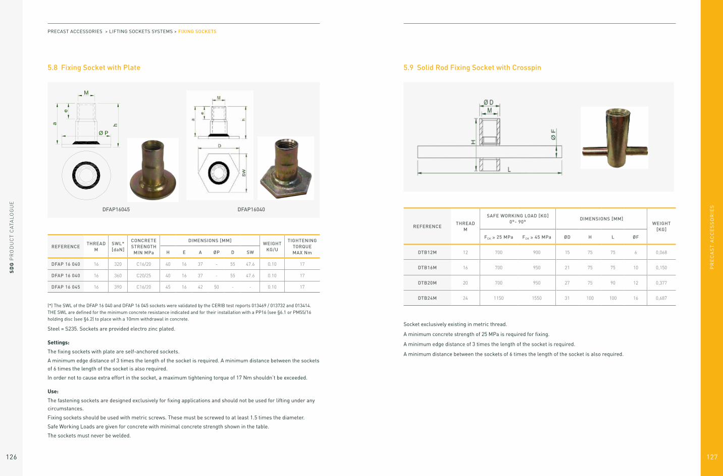
PR
EC
AS
T A
CC
ES
SO
RIE
S
SD
G P
RO
DU
CT
CA
TAL
OG
UE
126 127
5.8 Fixing Socket with Plate
DFAP16045 DFAP16040
(*) The SWL of the DFAP 16 040 and DFAP 16 045 sockets were validated by the CERIB test reports 013469 / 013732 and 013414. THE SWL are defined for the minimum concrete resistance indicated and for their installation with a PP16 (see §6.1 or PM55/16 holding disc (see §6.2) to place with a 10mm withdrawal in concrete.
Steel = S235. Sockets are provided electro zinc plated.
Settings:
The fixing sockets with plate are self-anchored sockets.
A minimum edge distance of 3 times the length of the socket is required. A minimum distance between the sockets
of 6 times the length of the socket is also required.
In order not to cause extra effort in the socket, a maximum tightening torque of 17 Nm shouldn’t be exceeded.
Use:
The fastening sockets are designed exclusively for fixing applications and should not be used for lifting under any
circumstances.
Fixing sockets should be used with metric screws. These must be screwed to at least 1.5 times the diameter.
Safe Working Loads are given for concrete with minimal concrete strength shown in the table.
The sockets must never be welded.
REFERENCETHREAD
MSWL* [daN]
CONCRETE STRENGTH
MIN MPa
DIMENSIONS [MM]WEIGHT
KG/U
TIGHTENING TORQUE MAX NmH E A ØP D SW
DFAP 16 040 16 320 C16/20 40 16 37 - 55 47.6 0.10 17
DFAP 16 040 16 360 C20/25 40 16 37 - 55 47.6 0.10 17
DFAP 16 045 16 390 C16/20 45 16 42 50 - - 0.10 17
PRECAST ACCESSORIES > LIFTING SOCKETS SYSTEMS > FIXING SOCKETS
5.9 Solid Rod Fixing Socket with Crosspin
Socket exclusively existing in metric thread.
A minimum concrete strength of 25 MPa is required for fixing.
A minimum edge distance of 3 times the length of the socket is required.
A minimum distance between the sockets of 6 times the length of the socket is also required.
REFERENCETHREAD
M
SAFE WORKING LOAD [KG] 0°- 90°
DIMENSIONS [MM]WEIGHT
[KG]
FCK ≥ 25 MPa FCK ≥ 45 MPa ØD H L ØF
DTB12M 12 700 900 15 75 75 6 0,068
DTB16M 16 700 950 21 75 75 10 0,150
DTB20M 20 700 950 27 75 90 12 0,377
DTB24M 24 1150 1550 31 100 100 16 0,687

SD
G P
RO
DU
CT
CA
TAL
OG
UE
128
PR
EC
AS
T A
CC
ES
SO
RIE
S
129
5.10 Fixing Socket
A minimum concrete strength of 25 MPa is required for fixing.
REFERENCETHREAD
M
SAFE WORKING LOAD [KG] DIMENSIONS [MM]WEIGHT
[KG]0°- 45° 45° - 90° ØD H E ØF
DTP 12M 12 500 250 15 60 22 10 0,031
DTP 16M 16 1200 600 21 80 27 13 0,110
DTP 20M 20 2000 1000 27 95 35 15 0,200
DTP 24M 24 2500 1250 31 100 38 18 0,270
DTP 30M 30 4000 2000 39,5 135 56 22,5 0,600
A stirrup must be placed in the hole of the socket.
SOCKETØ HA B500B
[MM]LENGTH OF THE STIRRUP L [MM]
BENDING ROLL ØB [MM]
DTP 12M 6 340 60
DTP 16M 10 510 100
DTP 20M 12 670 120
DTP 24M 14 740 140
DTP 30M 16 970 160
PRECAST ACCESSORIES > LIFTING SOCKETS SYSTEMS > FIXING SOCKETS
6. Holding Device
6.1 Plastic Nailing Plate
The plastic holding discs are designed to be fixed to the mould with nails.
The plastic holding discs are convenient for:
– the lifting sockets (Round thread – Rd)
– the fixing sockets (Metric thread – M).
They can be removed with a flat steel.
REFERENCETHREAD
MDIMENSION [MM]
ØDCOLOR
PP 10 10 40 Blue
PP 12 12 40 Orange
PP 16 16 55 Red
PP 20 20 55 Light green
PP 24 24 55 Dark grey
PP 30 30 70 Dark green
PP 36 36 70 Light blue
PP 42 42 96 Light grey
PP 52 52 96 Yellow
LIFTING SOCKETS SYSTEMS: HOLDING DEVICE

PR
EC
AS
T A
CC
ES
SO
RIE
S
SD
G P
RO
DU
CT
CA
TAL
OG
UE
130 131
6.2 Fixing Stud
The fixing studs are designed to fix the lifting sockets
(Round thread – Rd) or the fixing socket (Metric thread
– M) on the mould.
REFERENCETHREAD
M
DIMENSION [MM]COLOR
ØD L
TC 06 6 11 23 Green
TC 08 8 11 23 Light blue
TC 10 10 11 23 Yellow
TC 12 12 11 23 Red
TC 16 16 11 23 Black
PRECAST ACCESSORIES > LIFTING SOCKETS SYSTEMS > HOLDING DEVICE
6.3 Magnetic Nailing Plate
Smaller threads can be mounted on 70mm Diameter washers to increase grip strength.
Removal key = 6mm BTR hexagonal male key
except for the PM40/10: 5mm BTR hexagonal male key.
The dimensions of the Magnetic holding discs are identical to those of the Standard Plastic holding discs
(PP reference) so as to fit perfectly in case of use of a lifting eye (AL reference).
The magnetic holding discs are convenient for:
– the lifting sockets (Round thread - Rd)
– the fixing sockets (Metric thread - M).
The washer is available in 3 dimensions:
REFERENCE THREAD M / RD Ø D [MM] Ø d [MM]INSTALLED
MAGNETISM [KG]WEIGHT [KG]
PM40/10 10 40 30 20 0,08
PM40/12 12 40 30 20 0,08
PM40/16 16 40 30 20 0,08
Diameter 40mm
REFERENCE THREAD M / RD Ø D [MM] Ø d [MM]INSTALLED
MAGNETISM [KG]WEIGHT [KG]
PM70/30 30 70 60 100 0,30
PM70/36 36 70 60 100 0,30
Diameter 70mm
REFERENCE THREAD M / RD Ø D [MM] Ø d [MM]INSTALLED
MAGNETISM [KG]WEIGHT [KG]
PM55/12 12 55 45 50 0,15
PM55/16 16 55 45 50 0,15
PM55/20 20 55 45 50 0,15
PM55/24 24 55 45 50 0,15
Diameter 55mm

PR
EC
AS
T A
CC
ES
SO
RIE
S
133
SD
G P
RO
DU
CT
CA
TAL
OG
UE
132
7. Cap
7.1 Sealing Cap
The plastic caps prevent the dirt to go into the socket and create problem when screwing a lifting
loops or a screw inside.
The grey colored caps can be screwed. A slot on top allows to screw or unscrew the cap.
REFERENCE THREAD M/RDDIMENSIONS [MM]
COLOURØ d1 Ø d2 H
BP 06 6 9 5 6 White
BP 08 8 10 7 6 White
BP 10GRIS 10 11,5 8 8,5 Grey
BP 12GRIS 12 18,5 8,5 10 Grey
BP 16GRIS 16 25,5 12 12,5 Grey
BP 20GRIS 20 30,5 15,5 18 Grey
BP 20GRIS 20 30,5 15,5 18 Grey
BP 24GRIS 24 34,5 19 18 Grey
BP 30GRIS 30 43,5 25 21 Grey
BP 36GRIS 36 50 30 21.5 Grey
BP 42 42 50 39 16 White
BP 52 52 59 52 18 White
7.2 Data Clip
The data clip is designed to unable a clear identification of the lifting socket already casted into the concrete
because of its color and because of its marking.
REFERENCEADAPTED TO THE SOCKETS
WITH A RD THREAD
DIMENSIONS [MM]
COLOUR
Ø d1 Ø d2 H
BI 12 12 26 15 15 Orange
BI 16 16 31 21 15 Red
BI 20 20 37 27 15 Light green
BI 24 24 41 31 15 Dark grey
LIFTING SOCKETS SYSTEMS: CAP

PR
EC
AS
T A
CC
ES
SO
RIE
S
SD
G P
RO
DU
CT
CA
TAL
OG
UE
134 135
7.3 Data Clip with Ears
The data clip with ears is designed to enable a clear identification of the lifting socket already casted into the
concrete because of its color and because of its marking. Its ears enable to hold the additional transversal pull
rebars when necessary.
REFERENCEADAPTED TO THE SOCKETS
WITH A RD THREAD
DIMENSIONS [MM]
COLOUR
Ø D b Ø ds
BIO 12 12 26 8 8 Orange
BIO 16 16 32 10 8 Red
BIO 20 20 36 12 10 Light green
BIO 24 24 44 15 12 Dark grey
BIO 30 30 44 15 12 Dark green
PRECAST ACCESSORIES > LIFTING SOCKETS SYSTEMS > CAP

PR
EC
AS
T A
CC
ES
SO
RIE
S
137
SD
G P
RO
DU
CT
CA
TAL
OG
UE
136
Lifting with Spread Anchor Systems
List of spread anchor products 135
1. Design Method 138
1.1 Calculation assumptions 138
1.2 Drawing of the precast element and foreseen lifting method 138
1.3 Weight of the Element (P) 139
1.4 Formwork adhesion at the removal from the mould (A) 139
1.5 Position and determination of the number of efficient lifting points (n) 140
1.6 Sling angle and multiplication coefficient (Ce) 142
1.7 Lifting and handling dynamic coefficient (Ψdyn) 143
1.8 Resultant load by lifting point (F) 144
1.9 Concrete strength (fck) 01
2. Choice of Anchor 145
2.1 General consideration on Flat Anchors 146
2.2 Spread Anchor 147
2.3 Erection Anchor 149
2.4 Erection Anchor One Side 153
2.5 Two Hole Anchor 154
2.6 Flat Foot Anchor 156
2.7 Flat Plate Anchor 157
2.8 Sandwich Panel Anchor 158
3. Formers and Accessories 160
3.1 Spread Anchor System 161
3.2 Additional Cccessories for Formers 163
4. Lifting Eye 167
4.1 Quality system 169
4.2 Periodic control 169
5. Use and safety conditions 171
SPREAD ANCHOR 1.4T 2T 2.5T 4T 5T 7.5T 10T
F (MM) 30 30 30 40 40 60 60
G (MM) 6 10 10 12 15 16 20
L (MM) 160 130 150 320 180 260 370
200 240 420 520
The spread anchors can be provided in black or hot dip galvanized (G)
EYE ANCHOR 1.4T 2.5T 5T 7.5T 10T 7.5T 10T
F (MM) 30 30 40 60 60 60 60
G (MM) 6 10 15 15 20 16 20
L (MM) 90 90 120 160 170 260 370
G (KG) 0.11 0.18 0.49 1.04 1.40 420 520
The eye anchors can be provided in black or hot dip galvanized (G)
ERECTION ANCHOR 1.4T 2.5T 5T 7.5T 10T
1.4 x 200 2.5 x 230 5 x 290 7.5 x 320 10 x 390
F (MM) 55 55 70 95 95
G (MM) 6 10 15 15 20
L (MM) 200 230 290 320 390
G (KG) 0.68 0.80 1.65 3.61 4.40
The erection anchors can be provided in black or hot dip galvanized (G)
LIFTING WITH SPREAD ANCHOR SYSTEMS

PR
EC
AS
T A
CC
ES
SO
RIE
S
SD
G P
RO
DU
CT
CA
TAL
OG
UE
138 139
SPREAD ANCHOR RECESS FORMER 1.4T 2T 2.5T 4T 5T 7.5T 10T
2.5T 5T 10T
A (MM) 43 55 78
B (MM) 106 134 188
C (MM) 45 59 81
M M8 M8 M12
G (KG) 0.07 0.20 0.45
ERECTION ANCHOR ONE SIDE 2.5T
2.5 x 230
F (MM) 40
G (MM) 10
L (MM) 230
G (KG) 0.75
The erection anchors can be provided in black or hot dip galvanized (G)
PRECAST ACCESSORIES > LIFTING WITH SPREAD ANCHOR SYSTEMS
MAGNETIC FORMER 1.4T 2T 2.5T 4T 5T 7.5T 10T
REF RP025M RP050M RP100M
A (MM) 44 53 70
B (MM) 90 115 160
C (MM) 48 62 87
MAGNET (KG) 30 50 100
G (KG) 0.07 0.20 0.45
FIXING BOLT 1.4T 2T 2.5T 4T 5T 7.5T 10T
M M8 M8 M12
L (MM) 160 160 160
SPREAD ANCHOR RING CLUTCH 1.4T 2T 2.5T 4T 5T 7.5T 10T
2.5T 5T 10T
A (MM) 70 85 110
B (MM) 59 66 85
C (MM) 95 117 148
D (MM) 79 102 148
E (MM) 12 17 25
F (MM) 27 37 50
L (MM) 264 333 412
G (KG) 1.55 3.55 9.09

PR
EC
AS
T A
CC
ES
SO
RIE
S
141
SD
G P
RO
DU
CT
CA
TAL
OG
UE
140
1. Design MethodThe aim of this design method is to evaluate the load on cemented anchors of a reinforced precast concrete element in order to select the appropriate anchor.
This method is based on the most common
applications. If you have any doubt on the application,
the assumptions or any point mentioned in this
document, you should contact our Technical Department.
It is also essential that the assumptions are clearly
communicated to the companies in charge of the
handling and lifting operations, in order to ensure
that the assumptions are corresponding to the actual
handling and lifting conditions.
In order to define the force on the lifting anchors, all
the following points have to be taken into account:
– The technical drawing of the precast element and
the kinetics of handling
– The weight of the element (and of the formwork and
other accessories lifted with the element)
– The formwork adhesion at the removal from
the mould
– The number of efficient lifting points (and not the
number of actual lifting points)
– The sling angle
– The dynamic coefficient (lifting machinery)
To define the correct anchor to use (type, length, size)
it is also necessary to know:
– The concrete strength when the element is lifted
It is also necessary to distinguish between the handling
of the element in the precast factory and on the
construction site. All the calculations have to be done
for both cases.
All these points are detailed in the following
paragraphs.
In the first place, the technical drawing of the element
has to be considered, then the means by which it is to
be handled. It is necessary to distinguish between
the handling in the precast factory and on site.
1.1 Calculation assumptions
1.2 Drawing of the precast element and foreseen lifting methodThe adhesion force is:
A = qadh x S
This adhesion force must be added to the weight of the
element in order to calculate the force required to lift it.
In some cases, the adhesion force can be zero if the
concrete is not in contact with the mould (pre-stressed
beam for example).
The actual weight of the element must be considered.
It includes in particular:
– The weight of the concrete element (volume x
density). The reinforced concrete density is equal
to 2500 daN/m3 (or 25 kN/m3) in general.
– The weight of the formwork and accessories
lifted with the element.
The adhesion will depend on 2 factors:
– The surface area of the element in contact with
the formwork (S in m²). All the surfaces in contact
with the formwork need to be considered, included
inclined surfaces.
– The surface condition of the mould. This surface
condition is defined by an adhesion factor (qadh in
daN/m²)
This force is to be considered at the removal of the
element from the mould.
1.3 Weight of the Element (P)
1.4 Formwork adhesion at the removal from the mould (A)
Type of mould Adhesion factor qadh
Oiled steel mould, Plywood coated with oiled plastic 100 daN/m²
Varnished oiled wooden mould 200 daN/m²
Oiled rough wooden mould 300 daN/m²
Polyurethane matrix Consult the matrix supplier
LIFTING WITH SPREAD ANCHOR SYSTEMS: DESIGN METHOD

PR
EC
AS
T A
CC
ES
SO
RIE
S
SD
G P
RO
DU
CT
CA
TAL
OG
UE
142 143
Set up the lifting points symmetrically to the center of gravity.
Here are some examples of lifting point positions:
In the case of asymmetric loads relative to the centre
of gravity, traction efforts must be calculated for each
lifting point taking into account distances to the centre
of gravity.
1.5 Position and determination of the number of efficient lifting points (n)
SLAB
PANEL
ROTATION PIECE
BEAM
PIPE
F1 = F x F2 = F xB
A + BA
A + B
Example for a beam:
PRECAST ACCESSORIES > LIFTING WITH SPREAD ANCHOR SYSTEMS > DESIGN METHOD
Balanced system
Apparent lifting points = 4
Efficient lifting points = 4
Unbalanced System
Apparent lifting points = 4
Efficient lifting points = 2
It is possible that some lifting positions are not
appropriate for selected anchor types (see § 2). In
particular, minimum distances between lifting points and
minimum distances from the edges of the concrete have
to be maintained. A minimum coating may be required.
Based on the number of apparent lifting points and the
use or not of a balanced lifting system (such as a lifting
beam), the number of efficient lifting points is defined
as follows:
APPARENT LIFTING POINTSEFFICIENT LIFTING POINTS NUMBER (N)
WITH A BALANCED SYSTEM OTHERS LIFTING MEANS
4 4 2
3 3 2
2 2 2
Some examples:

PR
EC
AS
T A
CC
ES
SO
RIE
S
SD
G P
RO
DU
CT
CA
TAL
OG
UE
144 145
A multiplication coefficient Ce is generated by vertical forces (weight) on the slings.
For the calculation, angle β is to be considered as the angle between the vertical and the most inclined sling.
1.6 Sling angle and multiplication coefficient (Ce)
SLAB
BEAM
ROTATION PIECE
PIPE
β 0 15° 22,5° 30° 45° 60°
α = 2β 0 30° 45° 60° 90° 120°
Ce 1 1,035 1,082 1,155 1,414 2
L - 2 D 1,3 D D 0,7 D 0,6 D
PRECAST ACCESSORIES > LIFTING WITH SPREAD ANCHOR SYSTEMS > DESIGN METHOD
The values given in the table below are derived from the” Design and use of inserts for lifting and handling of
precast concrete - Elements”, CEN/TR 15728:2008.
The foreseen lifting system and the estimated values must be notified to the users (factory and site).
Dynamic coefficient required by type of element:
1.7 Lifting and handling dynamic coefficient (Ψdyn)
Ce = L == =1
cos (β)D
2 x sin (β)1
cos ( a ) 2
D
2 x sin ( a ) 2
Other angle:
β = angle between the vertical and the most inclined sling.
It is necessary to consider the worst-case scenario with the largest angle β.
LIFTING AND HANDLING MACHINE DYNAMIC COEFFICIENT ΨDYN
Tower crane, overhead crane and portal crane 1,2
Mobile crane 1,4
Lifting and moving on flat terrain 2-2,5
Lifting and moving on rough terrain 3-4
TYPE OF ELEMENT DYNAMIC COEFFICIENT ΨDYN
Pipe and sewer 2
Frame below 12T 1,6
Frame between 12 and 20T 1,4
Frame above 20T 1,2
Wall 1,4
Beam below 12T 1,6
Beam between 12 and 20T 1,4
Beam above 20T 1,2

SD
G P
RO
DU
CT
CA
TAL
OG
UE
146
PR
EC
AS
T A
CC
ES
SO
RIE
S
147
The resultant load for each lifting point is equal to:
The concrete strength has to be determined:
– When lifting the element from the mould in the Precast factory
– When transporting and installing on site
The minimum allowed resistance of the concrete is 10 MPa.
NOTE: Anchors used more than 10 times, must not to be subject to a force more than 0.6 times their safety
working load (SWL). It is necessary to check in this case that F < 0.6* SWL (Anchor).
This calculation must be done for the lifting activity in
the precast factory, on site, and for any other handling
activity of the precast element.
1.8 Resultant load by lifting point (F)
1.9 Concrete strength (fck)
F =(P + A) x Ce x Ψdyn
n
PRECAST ACCESSORIES > LIFTING WITH SPREAD ANCHOR SYSTEMS > DESIGN METHOD
2. Choice of Anchor
This choice can be made according to the resultant load
values by lifting point at the factory (Fu), and on site (Fc),
and from the concrete strength during the first lifting
at the precast factory and on site. The worst calculation
(worst case scenario) should be used to ensure the
anchor is suitable for all applications.
If you have any doubt about your calculation, you should
contact AdC Technical Department.
The anchor load capacity must be at least equal to the
highest calculated load value (Fu and Fc).
Various anchor types are available, and the choice
of anchor type to be used is made according to each
individual set up.
There are 4 major types of flat lifting anchors:
Spread Anchor
Flat Foot Anchor Eye Anchor Flat Plate Anchor
Sandwich Panel Anchor Erection Anchor Erection Anchor One Side
LIFTING WITH SPREAD ANCHOR SYSTEMS: CHOICE OF ANCHOR

PR
EC
AS
T A
CC
ES
SO
RIE
S
SD
G P
RO
DU
CT
CA
TAL
OG
UE
148 149
PRECAUTIONS TO BE TAKEN WHEN SETTING UP THE ANCHORS
– Never weld the anchors
– Always use the appropriate former for each
anchor type
– Anchors have to be slightly recessed from the
surface of the concrete (the recess is generated
by the appropriate former)
– The concrete element must have a minimum
standard reinforcement with FeE500
reinforcing bars.
ANTI-CORROSION PROTECTION
Anchors are provided in black (plain steel).
On request, anchors can be zinc-plated of hot dip
galvanized for additional anti-corrosion protection.
The Safe Working Load of the anchors is given for a
pulling load with a maximum inclination β of 30°.
In case of a pull load with an inclination β > 30°,
an angled pull reinforcement stirrup is necessary.
It must be placed as close as possible to the former.
2.1 General consideration on Flat Anchors
Angled Pull Reinforcement Stirrup
SWL ANCHOR (T)
SWLLIFTING EYE (T)
∅HA BAR(MM)
TOTAL LENGTH L (MM)
1.4
2.5
6 900
2.5 8 1200
4
5
10 1500
5 12 1550
7.5
10
14 2000
10 16 2300
14 26 20 2600
Reinforced ribbed steel B500B
PRECAST ACCESSORIES > LIFTING WITH SPREAD ANCHOR SYSTEMS > CHOICE OF ANCHOR
2.2 Spread Anchor
ANCHOR REFERENCE
SWL (T)LIFTING EYE (T)
F G L R S
PC014160 1.4
2.5 30
6 160
40 9PC020130 2 8 130
PC0252002.5 10
200
PC025250 250
PC040320 4
5 40
12 320
56 11PC050180
5
180
PC05024015
240
PC050400 400
PC075260
7.5
10 60
16
260
85 15
PC075300 300
PC075420 420
PC100300
10 20
300
PC100370 370
PC100520 520

PR
EC
AS
T A
CC
ES
SO
RIE
S
SD
G P
RO
DU
CT
CA
TAL
OG
UE
150 151
The anchorage in the concrete is produced by the foot
of the spread anchor creating a wrenching cone.
The anchorage resistance depends on:
– The concrete strength (fck)
– The length of the spread anchor (L)
– Distances to the edge of the concrete (TN)
– Distances between each anchor (TN)
The larger the wrenching cone, the more resistant the
anchorage. It is at its maximum when the distance
between the 2 anchors is greater than 3.5 times the
anchoring length (L) and the distance to the edge of the
concrete greater than 1.75 times L.
The following tables indicate minimum spacing
between 2 anchors and minimum thickness (Ep)
of a beam.
The concrete element must have a minimum standard reinforcement with reinforced ribbed steel B500B.
REFERENCESWL
(TONS)LENGTH
(MM)MINI SPACING
(MM)MINI THICKNESS EP (MM)
AT 15 MPA AT 25 MPA AT 25 MPA
PC0140160 1.4 160 560 80 60 60
PC0200130 2 130 455 200 140 110
PC0250150 2.5 150 525 220 160 120
PC0250200 2.5 200 700 150 90 80
PC0250250 2.5 250 875 120 90 80
PC0400320 4 320 1120 150 120 100
PC0500180 5 180 630 320 320 250
PC0500240 5 240 840 230 220 170
PC0500400 5 400 1400 140 140 120
PC0750260 7.5 260 910 480 340 270
PC0750300 7.5 300 1050 400 280 210
PC0750420 7.5 420 1470 240 150 130
PC1000300 10 300 1050 590 420 330
PC1000370 10 370 1295 460 310 240
PC1000520 10 520 1820 260 190 160
PRECAST ACCESSORIES > LIFTING WITH SPREAD ANCHOR SYSTEMS > CHOICE OF ANCHOR
The Safe Working Load for tilting up (=lateral load) is 50% lower than the Safe Working Load for axial lifting.
2.3 Erection Anchor
ANCHOR REFERENCE
SWL AXIAL (T)
SWL LATERAL (T)
LIFTING EYE (T)
F G L R S
PR012120 1.25 0.625 1.25 30 6 120 32
PR014200 1.4 0.7
2.5 55
6 200
40 9
PR025230 2.5 1.25 10 230
PR050290 5 2.5 5 70 15 290 56 11
PR075320 7.5 3.75
10 95
15 320
85 15
PR100390 10 5 20 390
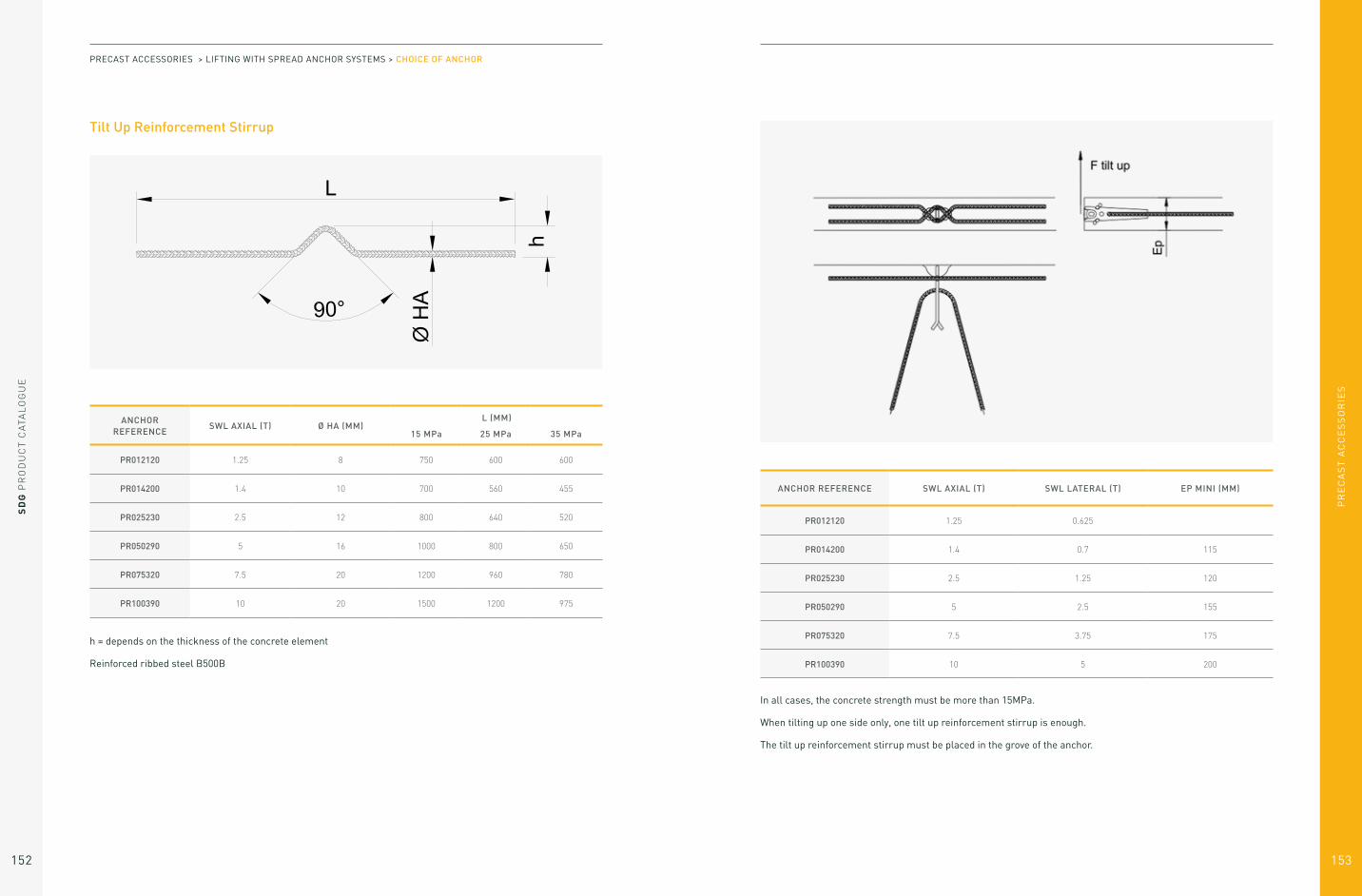
PR
EC
AS
T A
CC
ES
SO
RIE
S
SD
G P
RO
DU
CT
CA
TAL
OG
UE
152 153
Tilt Up Reinforcement Stirrup
ANCHOR REFERENCE
SWL AXIAL (T) Ø HA (MM)L (MM)
15 MPa 25 MPa 35 MPa
PR012120 1.25 8 750 600 600
PR014200 1.4 10 700 560 455
PR025230 2.5 12 800 640 520
PR050290 5 16 1000 800 650
PR075320 7.5 20 1200 960 780
PR100390 10 20 1500 1200 975
h = depends on the thickness of the concrete element
Reinforced ribbed steel B500B
PRECAST ACCESSORIES > LIFTING WITH SPREAD ANCHOR SYSTEMS > CHOICE OF ANCHOR
ANCHOR REFERENCE SWL AXIAL (T) SWL LATERAL (T) EP MINI (MM)
PR012120 1.25 0.625
PR014200 1.4 0.7 115
PR025230 2.5 1.25 120
PR050290 5 2.5 155
PR075320 7.5 3.75 175
PR100390 10 5 200
In all cases, the concrete strength must be more than 15MPa.
When tilting up one side only, one tilt up reinforcement stirrup is enough.
The tilt up reinforcement stirrup must be placed in the grove of the anchor.

PR
EC
AS
T A
CC
ES
SO
RIE
S
SD
G P
RO
DU
CT
CA
TAL
OG
UE
154 155
Axial Load Reinforcement Stirrup
To be placed in the bottom hole of the anchor.
L = total length
ANCHOR REFERENCE
SWL AXIAL (T) Ø HA (MM)L (MM)
15 MPa 25 MPa 35 MPa
PR012120 1.25 8 750 570 480
PR014200 1.4 10 720 560 480
PR025230 2.5 12 1020 790 660
PR050290 5 16 1490 1140 950
PR075320 7.5 20 1800 1380 1150
PR100390 10 25 1980 1540 1290
Reinforced ribbed steel B500B
PRECAST ACCESSORIES > LIFTING WITH SPREAD ANCHOR SYSTEMS > CHOICE OF ANCHOR
The dimensions of the tilt up reinforcement stirrup and
the axial reinforcement stirrup are the same than for the
erection anchor PR (refer to §2.2).
2.4 Erection Anchor One Side
ANCHOR REFERENCE
SWL AXIAL (T)
SWL LATERAL (T)
LIFTING EYE (T)
F G L R S
PS025230 2.5 1.25 2.5 40 10 230 40 9
PS050290 5 2.5 5 55 15 290 56 10
PS100390 10 5 10 80 20 390 85 15

PR
EC
AS
T A
CC
ES
SO
RIE
S
SD
G P
RO
DU
CT
CA
TAL
OG
UE
156 157
2.5 Two Hole Anchor
With its complementary reinforced steel bar, the eye anchor has a universal use.
The anchorage resistance is transmitted to the concrete via the reinforced steel bar.
Thus, the anchorage capacity depends on the diameter and the length of the associated reinforced steel bar.
The longer the bar, the more resistant the anchorage (within the SWL limit of the anchor).
ANCHOR REFERENCE
SWL (T)
LIFTING EYE (T)
F G L R S
PO014090 1.4
2.5 30
6 90
40 9
PO025090 2.5 10 90
PO050120 5 5 40 15 120 56 11
PO075160 7.5
10 60
15 160
85 15
PO100170 10 20 170
PO140240 14
26
80 20 240
120 15PO220300 22 90 25 300
PO260300 26 120 30 300
PRECAST ACCESSORIES > LIFTING WITH SPREAD ANCHOR SYSTEMS > CHOICE OF ANCHOR
The following table indicates the diameter and the total length of the reinforced steel bar to use.
REINFORCED RIBBED STEEL B500B, (ACCORDING TO NF A 35-080)
1,4 T 2,5 T 5 T 7.5 T 10 T 14 T 22 T 26 T
DIAMETER OF THE
REINFORCEMENT (MM)
10 12 16 20 25 28 28 2 x 28
CONCRETE AT 10 MPa
850 1 220 1 790 2 160 2 360 2 900 4 280 4 960
CONCRETE AT 15 MPa
720 1 020 1 490 1 800 1 980 2 420 3 520 4 070
CONCRETE AT 20 MPa
630 880 1 290 1 560 1 720 2 100 3 010 3 470
CONCRETE AT 25 MPa
560 790 1 140 1 380 1 540 1 870 2 650 3 050
CONCRETE AT 30 MPa
520 710 1 030 1 250 1 400 1 690 2 380 2 730
CONCRETE AT 35 MPa
480 660 950 1 150 1 290 1 560 2 170 2 480
CONCRETE AT 40 MPa
450 610 880 1 070 1 210 1 450 2 000 2 280
The eye anchor cannot be used under any circumstances without reinforcing steel.
The eye anchor is particularly adapted to narrow panels.
It is important to respect the diameters of the bending mandrel indicated in the standards covering the reinforcing
steel for reinforced concrete, in accordance to the Eurocode standard.
It is advisable to set up the reinforcing steel in a “V” form with a 30 ° angle. If the concrete element does not allow
it, it is possible to set up the reinforcing steel horizontally and to tie it to the lower wire mesh.

PR
EC
AS
T A
CC
ES
SO
RIE
S
SD
G P
RO
DU
CT
CA
TAL
OG
UE
158 159
2.6 Flat Foot Anchor
REFERENCE SWL LIFTING EYE F G E L R S
PP025075 2.5 T 2.5 T 30 10 94 75 40 10
PP050125 5 T 5 T 40 15 105 125 56 10
The flat foot anchor is particularly suitable for thin elements. It is used with the additional reinforcement shown
in the table below. The anchor’s foot and its complementary reinforcing steel must be located under the upper
reinforcement layer and ligated to the lower one. In use, the strength of the concrete must be at least 25 MPa. For
lower concrete strength, the SWL must be reduced by 20%. However, a minimum resistance of 15MPa is required.
The following table gives the diameter and total length of the necessary complementary reinforcement:
REFERENCE SWL ADDITIONAL REINFORCEMENT
PP025075 2.5 T 4 HA Ø8 long 300mm
PP050125 5 T 4 HA Ø12 long 500mm
Reinforced ribbed steel B500B
PRECAST ACCESSORIES > LIFTING WITH SPREAD ANCHOR SYSTEMS > CHOICE OF ANCHOR
2.7 Flat Plate Anchor
REFERENCE SWL LIFTING EYE F G A x A L R S
PAP025080 2.5 T 2.5 T 30 10 80 x 80 80 40 10
PAP050120 5 T 5 T 40 15 100 x 100 120 56 10
The flat plate anchor is particularly suitable for thin elements. It is used with the additional reinforcement shown
in the table below. The anchor’s foot and its complementary reinforcing steel must be located under the upper
reinforcement layer and ligated to the lower one. In use, the strength of the concrete must be at least 25 MPa. For
lower concrete strength, the SWL must be reduced by 20%. However, a minimum resistance of 15MPa is required.
The following table gives the diameter and total length of the necessary complementary reinforcement:
REFERENCE SWL ADDITIONAL REINFORCEMENT
PAP025080 2.5 T 4 HA Ø10 long 300mm
PAP050120 5 T 4 HA Ø12 long 450mm
Reinforced ribbed steel B500B

PR
EC
AS
T A
CC
ES
SO
RIE
S
SD
G P
RO
DU
CT
CA
TAL
OG
UE
160 161
2.8 Sandwich Panel Anchor
The shape of the anchor allows use in sandwich panels. The anchor is sealed in the load-bearing panel of the wall
(the thickest) while its head is at the gravity axis of the panel allowing vertical lifting. Additional reinforcements are
to be expected. A minimum concrete strength of 15 MPa is required.
2 additional reinforcing bars are required: a tension bar and a tilting stirrup.
ANCHOR REFERENCE
SWL TENSION
SWL TILTING
LIFTING EYE
F G L R S
PPS025250 2.5 T 0.8 T 2.5 T 40 10 250 40 10
PPS050300 5 T 1.8 T 5 T 55 15 300 56 10
PRECAST ACCESSORIES > LIFTING WITH SPREAD ANCHOR SYSTEMS > CHOICE OF ANCHOR
1. Tension bar
2. Tilting stirrup
To be placed in the inferior hole.
To be placed in the superior hole.
ANCHOR REFERENCE
SWL AXIAL (T)
Ø HA (MM)
L (MM)
PPS025250 2.5 T 14 800
PPS050300 5 T 16 1200
Reinforced ribbed steel B500B
ANCHOR REFERENCE
SWL AXIAL
(T)
SWLLATERAL
(T)
EPMINI(MM)
PPS025250 2.5 T 0.8 T 100
PPS050300 5 T 1.8 T 120
Minimal thickness of the load-bearing panel.
ANCHOR REFERENCE
SWL AXIAL
(T)
Ø HA (MM)
L (MM)
H MINI (MM)
PPS025250 2.5 T 10 600 ≥ 60
PPS050300 5 T 14 700 ≥ 80
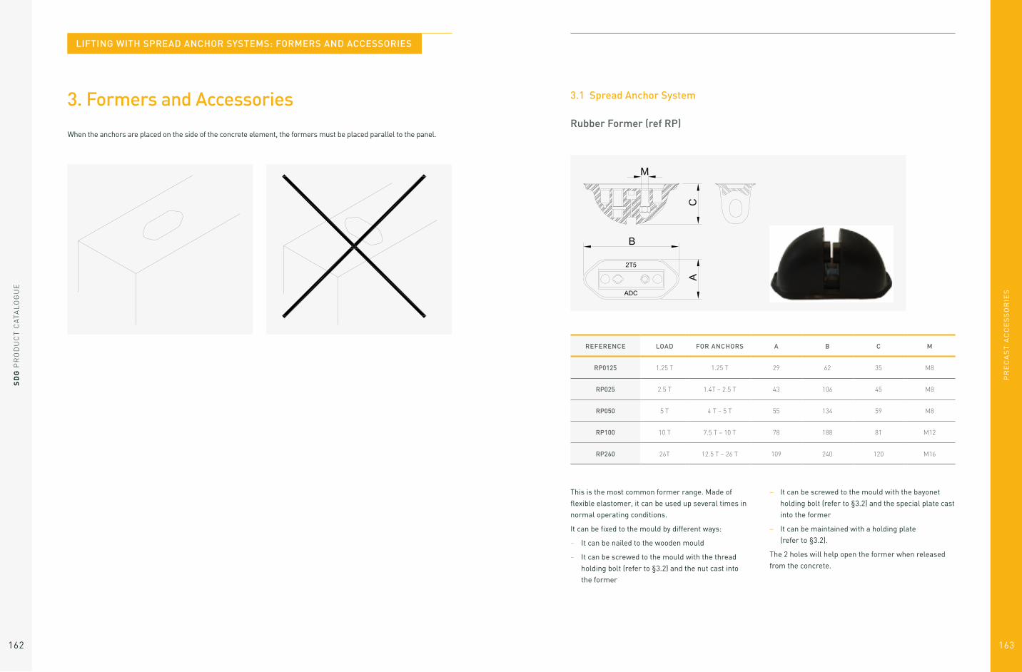
PR
EC
AS
T A
CC
ES
SO
RIE
S
163
SD
G P
RO
DU
CT
CA
TAL
OG
UE
162
3. Formers and Accessories
When the anchors are placed on the side of the concrete element, the formers must be placed parallel to the panel.
REFERENCE LOAD FOR ANCHORS A B C M
RP0125 1.25 T 1.25 T 29 62 35 M8
RP025 2.5 T 1.4T – 2.5 T 43 106 45 M8
RP050 5 T 4 T – 5 T 55 134 59 M8
RP100 10 T 7.5 T – 10 T 78 188 81 M12
RP260 26T 12.5 T – 26 T 109 240 120 M16
This is the most common former range. Made of
flexible elastomer, it can be used up several times in
normal operating conditions.
It can be fixed to the mould by different ways:
– It can be nailed to the wooden mould
– It can be screwed to the mould with the thread
holding bolt (refer to §3.2) and the nut cast into
the former
– It can be screwed to the mould with the bayonet
holding bolt (refer to §3.2) and the special plate cast
into the former
– It can be maintained with a holding plate
(refer to §3.2).
The 2 holes will help open the former when released
from the concrete.
3.1 Spread Anchor System
Rubber Former (ref RP)
LIFTING WITH SPREAD ANCHOR SYSTEMS: FORMERS AND ACCESSORIES

PR
EC
AS
T A
CC
ES
SO
RIE
S
SD
G P
RO
DU
CT
CA
TAL
OG
UE
164 165
REFERENCE LOAD FOR ANCHORS A B CMAGNETISM INSTALLED
RP025M 2.5 T 1.4T – 2.5 T 44 90 48 30 daN
RP050M 5 T 4 T – 5 T 53 115 62 50 daN
RP100M 10 T 7.5 T – 10 T 70 160 87 100 daN
Polyurethane former with cast in magnets.
This former is to be used on metallic moulds.
Magnetic Former (ref RP…M)
PRECAST ACCESSORIES > LIFTING WITH SPREAD ANCHOR SYSTEMS > FORMERS AND ACCESSORIES
3.2 Additional Accessories for Formers
A. Holding Plate
The holding plate can be nailed, screwed, welded and glued to the mould.
It is designed to maintain the rubber former on the mould.
REFERENCE LOAD A B ØD
PLM025 2.5 T 70 15 10
PLM050 5 T 85 30 10
PLM100 10 T 125 45 12

PR
EC
AS
T A
CC
ES
SO
RIE
S
SD
G P
RO
DU
CT
CA
TAL
OG
UE
166 167
The Magnetic holding plate allows the fixation on a metal mould without having to pierce it. Magnetism can be
increased or decreased on demand by adding or removing some magnets. It allows the elastomer former to be
maintained when the concrete is cast.
B. Magnetic Holding Plate
REFERENCE LOADINSTALLED
MAGNETISMA B C ØD
PLM025M 2.5 T 100 kg 70 15 12 10
PLM050M 5 T 100 kg 85 30 12 10
PLM100M 10 T 100 kg 125 45 12 12
PRECAST ACCESSORIES > LIFTING WITH SPREAD ANCHOR SYSTEMS > FORMERS AND ACCESSORIES
The thread holding bolt is designed to maintain the rubber former on the mould.
It is screwed in the cap nut cast into the rubber former.
C. Thread Holding Bolt
REFERENCE LOAD M L
2.5 T 8 160
5 T 8 160
10 T 12 160

SD
G P
RO
DU
CT
CA
TAL
OG
UE
168
PR
EC
AS
T A
CC
ES
SO
RIE
S
169
The bayonet holding bolt is designed to maintain the rubber former on the mould.
It is inserted into the bayonet connection of the rubber former and turned 90°.
D. Bayonet Holding Bolt
REFERENCE LOAD M L
BAIONETTEM8 2.5 T 8 160
BAIONETTEM8 5 T 8 160
BAIONETTEM10 10 T 12 180
PRECAST ACCESSORIES > LIFTING WITH SPREAD ANCHOR SYSTEMS > FORMERS AND ACCESSORIES
4. Lifting Eye
Ring Clutch
The ring clutch must be chosen to match the anchor load. Under no circumstances should a lifting eye be used
with a different capacity to that of the anchor, even if the load capacity of the lifting eye is superior to the load
capacity of the anchor.
REFERENCE SWL FOR ANCHORS A B C D E F L
PA025 2.5 T 1.4T – 2.5 T 70 59 95 79 12 27 264
PA050 5 T 4 T – 5 T 85 66 117 102 17 37 333
PA100 10 T 7.5 T – 10 T 110 85 148 148 25 50 412
PA260 26 T 12.5 T – 26 T 160 120 210 209 30 72 605
LIFTING WITH SPREAD ANCHOR SYSTEMS: LIFTING EYE
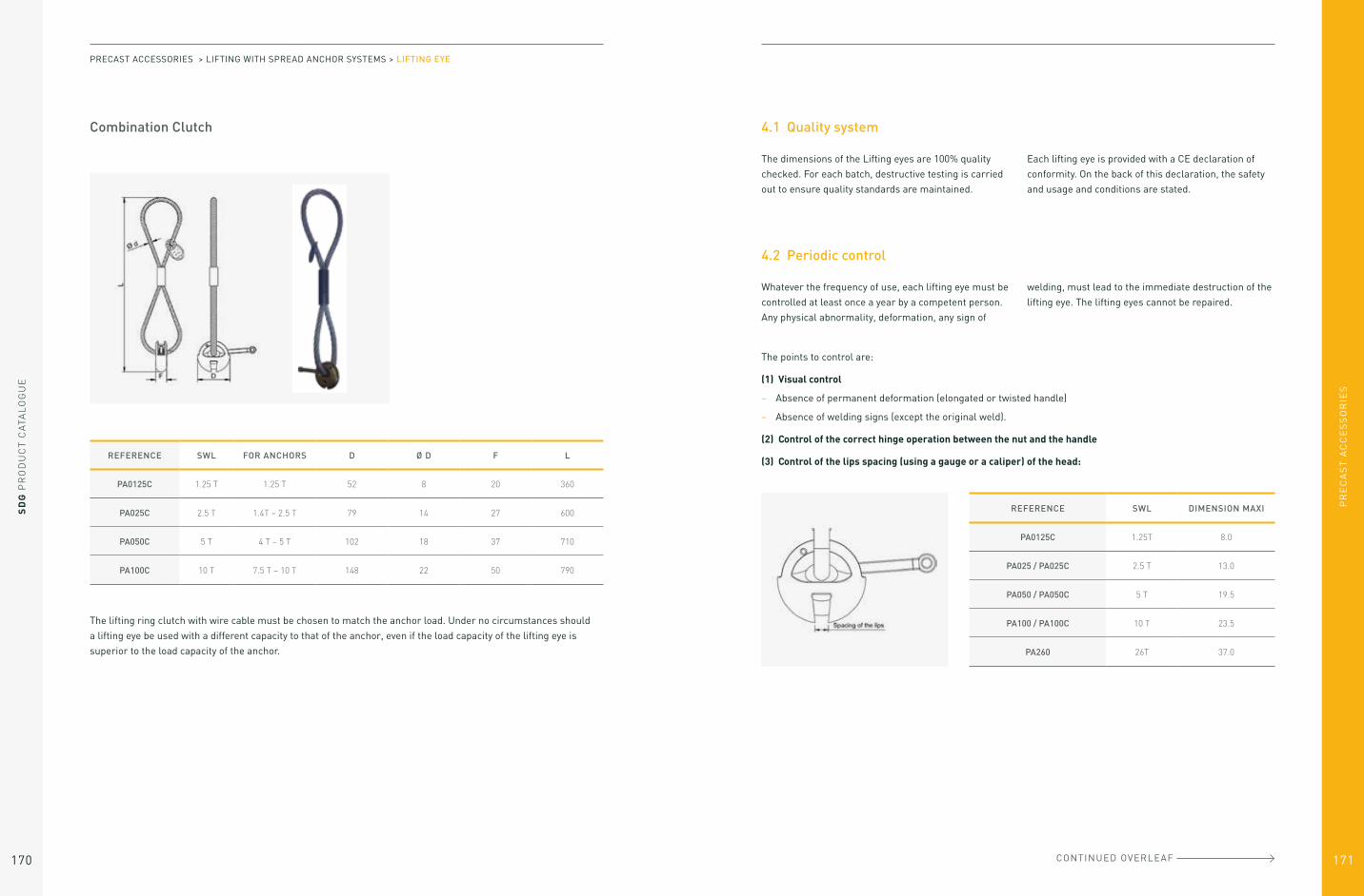
PR
EC
AS
T A
CC
ES
SO
RIE
S
SD
G P
RO
DU
CT
CA
TAL
OG
UE
170 171
Combination Clutch
The lifting ring clutch with wire cable must be chosen to match the anchor load. Under no circumstances should
a lifting eye be used with a different capacity to that of the anchor, even if the load capacity of the lifting eye is
superior to the load capacity of the anchor.
REFERENCE SWL FOR ANCHORS D Ø D F L
PA0125C 1.25 T 1.25 T 52 8 20 360
PA025C 2.5 T 1.4T – 2.5 T 79 14 27 600
PA050C 5 T 4 T – 5 T 102 18 37 710
PA100C 10 T 7.5 T – 10 T 148 22 50 790
PRECAST ACCESSORIES > LIFTING WITH SPREAD ANCHOR SYSTEMS > LIFTING EYE
4.1 Quality system
4.2 Periodic control
The dimensions of the Lifting eyes are 100% quality
checked. For each batch, destructive testing is carried
out to ensure quality standards are maintained.
Each lifting eye is provided with a CE declaration of
conformity. On the back of this declaration, the safety
and usage and conditions are stated.
Whatever the frequency of use, each lifting eye must be
controlled at least once a year by a competent person.
Any physical abnormality, deformation, any sign of
welding, must lead to the immediate destruction of the
lifting eye. The lifting eyes cannot be repaired.
The points to control are:
(1) Visual control
– Absence of permanent deformation (elongated or twisted handle)
– Absence of welding signs (except the original weld).
(2) Control of the correct hinge operation between the nut and the handle
(3) Control of the lips spacing (using a gauge or a caliper) of the head:
REFERENCE SWL DIMENSION MAXI
PA0125C 1.25T 8.0
PA025 / PA025C 2.5 T 13.0
PA050 / PA050C 5 T 19.5
PA100 / PA100C 10 T 23.5
PA260 26T 37.0
CONTINUED OVERLEAF
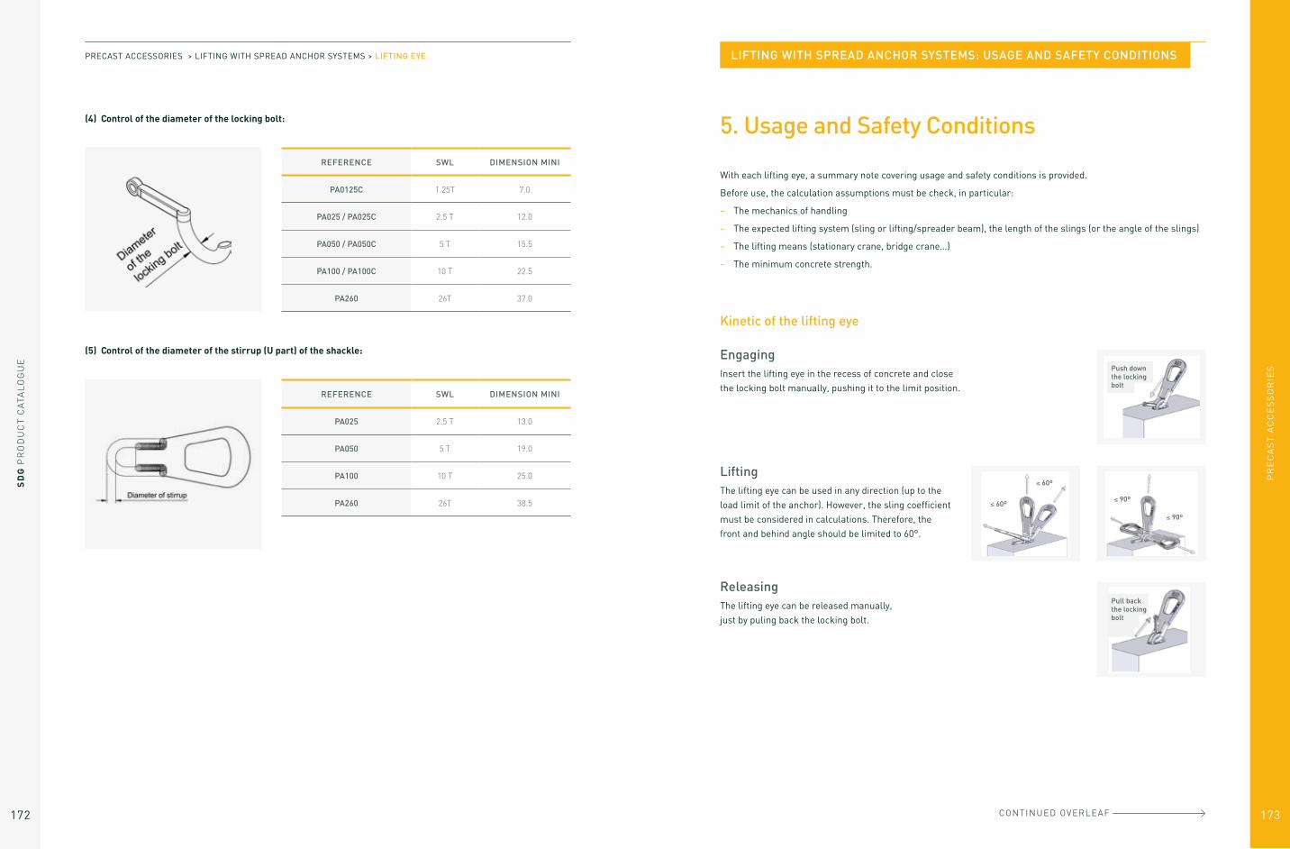
SD
G P
RO
DU
CT
CA
TAL
OG
UE
172
PR
EC
AS
T A
CC
ES
SO
RIE
S
173
(4) Control of the diameter of the locking bolt:
(5) Control of the diameter of the stirrup (U part) of the shackle:
REFERENCE SWL DIMENSION MINI
PA0125C 1.25T 7.0
PA025 / PA025C 2.5 T 12.0
PA050 / PA050C 5 T 15.5
PA100 / PA100C 10 T 22.5
PA260 26T 37.0
REFERENCE SWL DIMENSION MINI
PA025 2.5 T 13.0
PA050 5 T 19.0
PA100 10 T 25.0
PA260 26T 38.5
PRECAST ACCESSORIES > LIFTING WITH SPREAD ANCHOR SYSTEMS > LIFTING EYE
5. Usage and Safety Conditions
With each lifting eye, a summary note covering usage and safety conditions is provided.
Before use, the calculation assumptions must be check, in particular:
– The mechanics of handling
– The expected lifting system (sling or lifting/spreader beam), the length of the slings (or the angle of the slings)
– The lifting means (stationary crane, bridge crane…)
– The minimum concrete strength.
Kinetic of the lifting eye
EngagingInsert the lifting eye in the recess of concrete and close
the locking bolt manually, pushing it to the limit position.
LiftingThe lifting eye can be used in any direction (up to the
load limit of the anchor). However, the sling coefficient
must be considered in calculations. Therefore, the
front and behind angle should be limited to 60°.
ReleasingThe lifting eye can be released manually,
just by puling back the locking bolt.
Push down the locking bolt
≤ 60º
≤ 60º
≤ 90º
≤ 90º
Pull back the locking bolt
CONTINUED OVERLEAF
LIFTING WITH SPREAD ANCHOR SYSTEMS: USAGE AND SAFETY CONDITIONS

PR
EC
AS
T A
CC
ES
SO
RIE
S
SD
G P
RO
DU
CT
CA
TAL
OG
UE
174 175
BEFORE USE
To do
– You must check that the safe working load of the anchor is the same as the safe
working load of the lifting eye.
– The length of the slings should be at least twice the distance between the
anchors, in order to have an angle of 30° between the slings. It is possible to have
a bigger angle only if it has been considered in calculations. It is always better to
use a lifting beam.
– The concrete strength should be at least equal to that used in the calculations.
The minimum concrete strength is 15 MPa.
– The locking bolt must be fully closed and pushed to the limit position up to resting
on the concrete.
– For cable rings, make sure that the diameter of
the hook or shackle attached to the cable, is not
less than 2.5 times the diameter of the cable of the
lifting eye. We recommend, if possible, a diameter
greater than 5 times the diameter of the cable.
Not to do
– You must not break the concrete around the anchor.
The lifting eye hooks onto the anchor without any other action.
– You must not weld the anchor nor the lifting eye, for whatever reason.
30º max. (except special calculation)
Locking bolt resting on concrete
PRECAST ACCESSORIES > LIFTING WITH SPREAD ANCHOR SYSTEMS > USAGE AND SAFETY CONDITIONS
On the left position, the shackle may lock within the clutch housing. A narrow lifting cable angle will cause the shackle to become bent. The problem can be overcome by turning the shackle through approximately 45° (left drawing).
– Never be in one of the 3 following dangerous positions:
If the shakle is under the head of the lifting ring at the time of application of the load, the stirrup may bent.
If the lifting eye is pulled towards the top surface of the precast, the shackle may bend on the edge of the precast.
IN USE
– When precast concrete elements are transported by construction company, they are subject to shock and
impact loads. This factor increases the load on the anchor by several times the dead-weight and should be
taken into account in load calculations. Therefore, care should be taken in transporting the elements on site
– When the anchors are used to lift a unit from a mould, the adhesion between the freshly cast concrete and the
mould increase the forces on the anchors.
MAINTENANCE
– All lifting eye must be controlled at least once a year by a competent person. The lifting eye must not show any
sign of deformity
– The lifting eye cannot be repaired.
GENERAL
– The lifting eye must be used only for lifting precast concrete elements
– Users of the lifting eyes must be familiar with the usage and safety instructions
– All usage and safety instructions must be respected when you lifting eyes are used.

PR
EC
AS
T A
CC
ES
SO
RIE
S
177
SD
G P
RO
DU
CT
CA
TAL
OG
UE
176
Lifting with Spherical Anchor Systems
List of spherical anchor products 175
1. Sizing Methods 184
1.1 Design process 184
1.2 Calculation assumptions 184
1.3 Drawing of the Precast element
and expected lifting process 184
1.4 Weight of the Element (P) 185
1.5 Formwork adhesion at the removal
from the mould (A) 185
1.6 Location and determination of the
number of efficient lifting points (n) 186
1.7 Sling angle and multiplication
coefficient (Ce) 188
1.8 Lifting and handling dynamic
coefficient (Cd) 189
1.9 Resultant load by lifting point (F) 190
1.10 Concrete resistance (fck) 190
2. Choice of Anchor 191
2.1 Lift Head Anchor 193
2.2 Double Head Anchor 201
2.3 Eye Anchor 202
2.4 Flat End Anchor 204
2.5 Rebar Anchor 205
2.6 Plate Anchor 207
3. Choice of Former 209
3.1 Formers for Lift Head Anchors,
Eye Anchors, and Foot & Eye Anchors 211
3.2 Additional Accessories for Formers 216
3.3 Formers for Double Head Anchors 218
4. Lift Head Shackle 220
4.1 Quality system 221
4.2 Periodic control 221
4.3 Remote decoupling 221
5. Use and safety conditions 222
ACCESSORIES 1.3T 2.5T 5T 7.5T 10T 15T 20T 32T
LIFT HEAD ANCHOR REF.AP
013…AP
025…AP
050…AP
075…AP
100…AP
50…AP
200…A
320…
T (MM) 18 25 36 46 46 69 69 88
C (MM) 10 14 20 24 28 34 38 50
P (MM) 25 35 50 60 70 85 98 135
L (MM) 40 45 75 100 115 140 200 280
50 55 85 100 115 140 200 280
55 65 95 120 135 165 240 320
65 75 120 140 150 200 250 500
85 85 180 165 170 300 340 700
120 120 240 200 200 400 500
170 140 340 240 250
240 170 300 340
210
240
280
The lift head anchors can be provided black, electro zinc plated (Z) or hot dip galvanised (G).
LIFTING WITH SPHERICAL ANCHOR SYSTEMS

PR
EC
AS
T A
CC
ES
SO
RIE
S
SD
G P
RO
DU
CT
CA
TAL
OG
UE
178 179
ACCESSORIES 1.3T 2.5T 5T 7.5T 10T 15T 20T 32T
DOUBLE HEAD ANCHOR REF.AM
013…AM
025…AM
050…
T (MM) 18 25 36
C (MM) 10 14 20
P (MM) 25 35 50
L (MM) 55 55 85
65 65 120
75 85 180
85 120 240
120 170
240 240
PRECAST ACCESSORIES > LIFTING WITH SPHERICAL ANCHOR SYSTEMS
ACCESSORIES 1.3T 2.5T 5T 7.5T 10T 15T 20T 32T
EYE ANCHOR REF.AO
130065AO
025090AO
050120AO
100180AO
200250AO
320200
T (MM) 18 25 36 46 69 88
C (MM) 10 14 20 28 38 50
L (MM) 65 90 120 180 250 300
G (KG) 0.06 0.16 0.40 1.16 3.17 6.34
REF.AO
050090AO
100115
T (MM) 36 46
C (MM) 20 28
L (MM) 90 115
G (KG) 0.35 0.82
The eye anchors can be provided black, electro zinc plated (Z) or hot dip galvanised (G).
FOOT & EYE ANCHOR REF.AOP
013050AOP
02565AOP
050080
T (MM) 18 25 36
C (MM) 10 14 20
P (MM) 22 35 47
L (MM) 50 65 80
G (KG) 0.06 0.17 0.38
The foot & eye anchors can be provided black, electro zinc plated (Z) or hot dip galvanised (G).

PR
EC
AS
T A
CC
ES
SO
RIE
S
SD
G P
RO
DU
CT
CA
TAL
OG
UE
180 181
ACCESSORIES 1.3T 2.5T 5T 7.5T 10T 15T
REBAR ANCHOR REF.AA
025400AA
05080AA
100870AA
1501080
T (MM) 25 36 46 69
C (MM 14 20 28 32
L (MM) 400 580 870 1080
G (KG) 0.70 1.43 4.30 7.00
REF.AA
025520
T (MM) 25
C (MM) 14
L (MM) 520
G (KG) 0.80
The rebar anchors can be provided black, electro zinc plated (Z) or hot dip galvanised (G).
PLATE ANCHOR REF.AS
025055AS
050065AS
100115
L (MM) 55 65 115
AXB (MM) 70x70 90x90 90x90
E (MM) 6 8 10
G (KG) 0.34 0.74 1.09
REF.AS
025120AS
050095
L (MM) 120 95
AXB (MM) 70x70 90x90
E (MM) 6 8
G (KG) 0.42 0.80
The plate anchors can be provided black, electro zinc plated (Z) or hot dip galvanised (G).
PRECAST ACCESSORIES > LIFTING WITH SPHERICAL ANCHOR SYSTEMS
ACCESSORIES 1.3T 2.5T 5T 7.5T 10T 15T 20T 32T
ROUND RUBBER FORMER WITH STUD
REF.REC 013
REC 025
REC 050
REC 075
REC 100
REC 150
REC 200
REC 320
D (MM) 60 74 94 118 118 160 160 204
T (MM) 6.5 6.5 8.5 10.5 10.5 10.5 10.5 10.5
A (MM) 9 13 15.5 18 18 19 19 19
M M8 M10 M10 M12 M12 M12 M12 M12
G (KG) 0.13 0.21 0.40 0.74 0.62 1.43 1.30 3.60
ROUND RUBBER FORMER REF.RE 013
RE 025
RE 050
RE 075
RE 100
RE 150
RE 200
RE 320
D (MM) 60 74 94 118 118 160 160 204
T (MM) 6.5 6.5 8.5 10.5 10.5 10.5 10.5 10.5
A (MM) 6 10 11.5 14 14 16 16 14
G (KG) 0.08 0.16 0.29 0.54 0.42 1.19 1.06 3.40
NARROW RUBBER FORMER WITH STUD
REF.REEC 013
REEC 025
REEC 050
REEC 075
REEC 100
REEC 150
REEC 200
REEC 320
D (MM) 60 74 94 118 160
T (MM) 6.5 6.5 8.5 10.5 10.5
A (MM) 9 13 15.5 18 19
M M8 M10 M10 M12 M12
G (KG) 0.11 0.17 0.35 0.73 1.58
NARROW RUBBER FORMER
REF.REE 013
REE 025
REE 050
REE 075
REE 100
REE 150
REE 200
REE 320
D (MM) 60 74 94 118 160
F (MM) 43 53 69 85 124
T (MM) 6.5 6.5 8.5 10.5 10.5
A (MM) 6 10 11.5 14 16
G (KG) 0.06 0.12 0.24 0.53 1.34
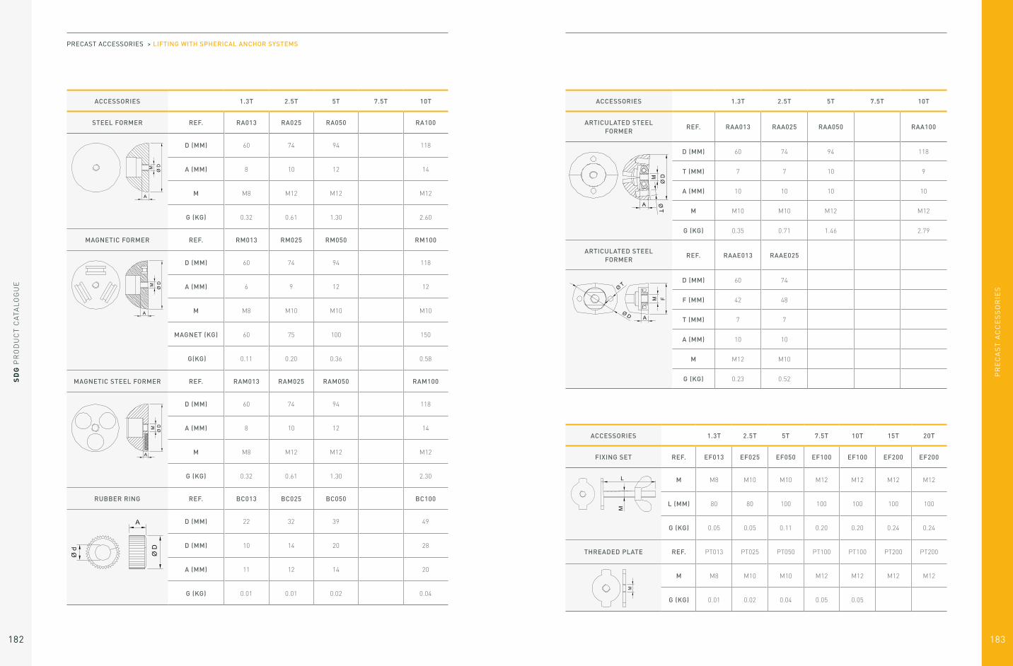
PR
EC
AS
T A
CC
ES
SO
RIE
S
SD
G P
RO
DU
CT
CA
TAL
OG
UE
182 183
ACCESSORIES 1.3T 2.5T 5T 7.5T 10T
STEEL FORMER REF. RA013 RA025 RA050 RA100
D (MM) 60 74 94 118
A (MM) 8 10 12 14
M M8 M12 M12 M12
G (KG) 0.32 0.61 1.30 2.60
MAGNETIC FORMER REF. RM013 RM025 RM050 RM100
D (MM) 60 74 94 118
A (MM) 6 9 12 12
M M8 M10 M10 M10
MAGNET (KG) 60 75 100 150
G(KG) 0.11 0.20 0.36 0.58
MAGNETIC STEEL FORMER REF. RAM013 RAM025 RAM050 RAM100
D (MM) 60 74 94 118
A (MM) 8 10 12 14
M M8 M12 M12 M12
G (KG) 0.32 0.61 1.30 2.30
RUBBER RING REF. BC013 BC025 BC050 BC100
D (MM) 22 32 39 49
D (MM) 10 14 20 28
A (MM) 11 12 14 20
G (KG) 0.01 0.01 0.02 0.04
PRECAST ACCESSORIES > LIFTING WITH SPHERICAL ANCHOR SYSTEMS
ACCESSORIES 1.3T 2.5T 5T 7.5T 10T
ARTICULATED STEEL FORMER
REF. RAA013 RAA025 RAA050 RAA100
D (MM) 60 74 94 118
T (MM) 7 7 10 9
A (MM) 10 10 10 10
M M10 M10 M12 M12
G (KG) 0.35 0.71 1.46 2.79
ARTICULATED STEEL FORMER
REF. RAAE013 RAAE025
D (MM) 60 74
F (MM) 42 48
T (MM) 7 7
A (MM) 10 10
M M12 M10
G (KG) 0.23 0.52
ACCESSORIES 1.3T 2.5T 5T 7.5T 10T 15T 20T
FIXING SET REF. EF013 EF025 EF050 EF100 EF100 EF200 EF200
M M8 M10 M10 M12 M12 M12 M12
L (MM) 80 80 100 100 100 100 100
G (KG) 0.05 0.05 0.11 0.20 0.20 0.24 0.24
THREADED PLATE REF. PT013 PT025 PT050 PT100 PT100 PT200 PT200
M M8 M10 M10 M12 M12 M12 M12
G (KG) 0.01 0.02 0.04 0.05 0.05

PR
EC
AS
T A
CC
ES
SO
RIE
S
SD
G P
RO
DU
CT
CA
TAL
OG
UE
184 185
ACCESSORIES 1.3T 2.5T 5T
TIGHTENING FORMER REF. RC013 RC025 RC050
D(MM) 60 74 94
A(MM) 9 11 14
M M8 M10 M10
G(KG) 0.10 0.19 0.23
MAGNETIC TIGHTENING FORMER
REF. RCM013 RCM025 RCM050
D(MM) 60 74 94
A(MM) 9 11 14
M M8 M10 M10
MAGNET (KG) 60 60 100
G(KG) 0.15 0.20 0.25
PRECAST ACCESSORIES > LIFTING WITH SPHERICAL ANCHOR SYSTEMS
ACCESSORIES 1.3T 2.5T 5T
INTERNAL MAGNETIC FORMER
REF. RI013 RI025 RI050
D (MM) 60 74 94
A (MM) 9 11 14
M M8 M10 M10
G (KG) 0.45 0.88 1.60
INTERNAL & EXTERNAL MAGNETIC FORMER
REF. RIM013 RIM025
D (MM) 60 74
A (MM) 9 11
M M8 M10
MAGNET (KG)
G (KG) 0.45 0.88
ACCESSORIES 1.3T 2.5T 5T 7.5T 10T 15T 20T 32T
LIFT HEAD SHACKLE REF.AN 013
AN 025
AN 050
AN 100
AN 200
AN 320
A (MM) 70 85 88 112 150 189
B(MM) 46 58 70 84 118 175
C(MM) 74 88 118 160 186 269
D(MM) 20 25 37 50 75 100
E(MM) 12 14 16 26 30 45
G(KG) 0.89 1.62 3.18 9.70 26.20 45.80

PR
EC
AS
T A
CC
ES
SO
RIE
S
187
SD
G P
RO
DU
CT
CA
TAL
OG
UE
186
1. Sizing Methods
The aim of this design process is the evaluation of
the load on cemented anchors in reinforced Precast
concrete in order to select the appropriate anchor.
This method is based on the most common applications.
If you have any doubt on the application, the
assumptions or any points mentioned in this document,
you should contact the SDG Technical Department.
It is also essential that the assumptions are clearly
communicated to the organizations tasked with the
handling and lifting operations, to ensure that the
assumptions are representative of the actual handling
and lifting conditions.
To define the force on the lifting anchors, all of the
following points must be considered:
– The technical drawing of the Precast element and
the mechanics of handling
– The weight of the element (and of the formwork and
other accessories lifted with the element)
– The formwork adhesion at the removal from
the mould
– The number of efficient lifting points (and not the
number of actual lifting points)
– The sling angle
– The dynamic coefficient (lifting machinery)
To define the correct anchor to use (type, length, size) it
is also necessary to know:
– The concrete strength when the element is lifted.
It is also necessary to distinguish between the handling
of the element in the precast factory and on the
construction site. All the calculations have to be done
for both cases.
All these points are detailed in the following
paragraphs.
1.1 Design process
1.2 Calculation assumptions
Firstly, the technical drawing of the element has to be
considered, and the means by which it is to be handled.
It is necessary to distinguish between the handling in
the precast factory and on site.
1.3 Drawing of the Precast element and expected lifting process The adhesion force is:
A = qadh x S
This adhesion force must be added to the weight of the
element in order to calculate the force required to lift it.
In some cases, the adhesion force can be zero if the
concrete is not in contact with the mould (pre-stressed
beam for example).
The actual weight of the element must be considered.
It includes in particular:
– The weight of the concrete element (volume x
density). The reinforced concrete density is equal
to 2500 daN/m3 (or 25 kN/m3) in general.
– The weight of the formwork and accessories
lifted with the element.
The adhesion will depend on 2 factors:
– The surface area of the element in contact with
the formwork (S in m²). All the surfaces in contact
with the formwork need to be considered, included
inclined surfaces.
– The surface condition of the mould. This surface
condition is defined by an adhesion factor (qadh in
daN/m²)
This force is to be considered at the removal of the
element from the mould.
1.4 Weight of the Element (P)
1.5 Formwork adhesion at the removal from the mould (A)
Type of mould Adhesion factor qadh
Oiled steel mould, Plywood coated with oiled plastic 100 daN/m²
Varnished oiled wooden mould 200 daN/m²
Oiled rough wooden mould 300 daN/m²
Polyurethane matrix Consult the matrix supplier
LIFTING WITH SPHERICAL ANCHOR SYSTEMS: SIZING METHODS

PR
EC
AS
T A
CC
ES
SO
RIE
S
SD
G P
RO
DU
CT
CA
TAL
OG
UE
188 189
Set up the lifting points symmetrically to the center of gravity.
Here are some examples of lifting point positions:
1.6 Location and determination of the number of efficient lifting points (n)
SLAB
PANEL
ROTATION PIECE
BEAM
PIPE
PRECAST ACCESSORIES > LIFTING WITH SPHERICAL ANCHOR SYSTEMS > SIZING METHODS
Balanced system
Apparent lifting points = 4
Efficient lifting points = 4
Unbalanced System
Apparent lifting points = 4
Efficient lifting points = 2
It is possible that some lifting positions are not
appropriate for selected anchor types (see § 2). In
particular, minimum distances between lifting points and
minimum distances from the edges of the concrete have
to be maintained. A minimum coating may be required.
Based on the number of apparent lifting points and the
use or not of a balanced lifting system (such as a lifting
beam), the number of efficient lifting points is defined
as follows:
APPARENT LIFTING POINTSEFFICIENT LIFTING POINTS NUMBER (N)
WITH A BALANCED SYSTEM OTHERS LIFTING MEANS
4 4 2
3 3 2
2 2 2
Some examples:
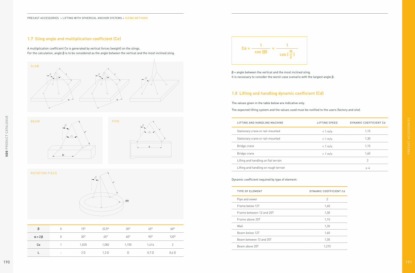
PR
EC
AS
T A
CC
ES
SO
RIE
S
SD
G P
RO
DU
CT
CA
TAL
OG
UE
190 191
A multiplication coefficient Ce is generated by vertical forces (weight) on the slings.
For the calculation, angle β is to be considered as the angle between the vertical and the most inclined sling.
1.7 Sling angle and multiplication coefficient (Ce)
SLAB
BEAM
ROTATION PIECE
PIPE
β 0 15° 22,5° 30° 45° 60°
α = 2β 0 30° 45° 60° 90° 120°
Ce 1 1,035 1,082 1,155 1,414 2
L - 2 D 1,3 D D 0,7 D 0,6 D
PRECAST ACCESSORIES > LIFTING WITH SPHERICAL ANCHOR SYSTEMS > SIZING METHODS
The values given in the table below are indicative only.
The expected lifting system and the values used must be notified to the users (factory and site).
Dynamic coefficient required by type of element:
1.8 Lifting and handling dynamic coefficient (Cd)
Ce = =1
cos (β)1
cos ( α )
2
β = angle between the vertical and the most inclined sling.
It is necessary to consider the worst-case scenario with the largest angle β.
LIFTING AND HANDLING MACHINE LIFTING SPEED DYNAMIC COEFFICIENT Cd
Stationary crane or rail-mounted < 1 m/s 1,15
Stationary crane or rail-mounted > 1 m/s 1,30
Bridge crane < 1 m/s 1,15
Bridge crane > 1 m/s 1,60
Lifting and handling on flat terrain 2
Lifting and handling on rough terrain ≥ 4
TYPE OF ELEMENT DYNAMIC COEFFICIENT Cd
Pipe and sewer 2
Frame below 12T 1,60
Frame between 12 and 20T 1,30
Frame above 20T 1,15
Wall 1,30
Beam below 12T 1,60
Beam between 12 and 20T 1,30
Beam above 20T 1,215

SD
G P
RO
DU
CT
CA
TAL
OG
UE
192
PR
EC
AS
T A
CC
ES
SO
RIE
S
193
The resultant load for each lifting point is equal to:
The concrete strength has to be determined:
– When lifting the element from the mould in the Precast factory
– When transporting and installing on site
The minimum permitted resistance of the concrete is 10 MPa.
NOTE: Anchors used more than 10 times, must not to be subject to a force more than 0.6 times their safety working load (SWL). It is necessary to check in this case that F < 0.6* SWL (Anchor).
This calculation must be done for the lifting activity in
the Precast factory, on site, and for any other handling
activity of the precast element.
1.9 Resultant load by lifting point (F)
1.10 Concrete resistance (fck)
F =(P + A) x Ce x Cd
n
PRECAST ACCESSORIES > LIFTING WITH SPHERICAL ANCHOR SYSTEMS > SIZING METHODS
2. Choice of Anchor
This choice can be made according to the resultant
load values by lifting point in the factory (Fu), and
on site (Fc), and from the concrete resistance at
the first lifting or on site. The most unfavourable
calculation (worst case scenario) is used to ensure
the anchor is suitable for all applications.
If you have any doubt about your calculation, you should
contact the SDG Technical Department.
The anchor load capacity must be at least equal to the
highest load value (Fu and Fc) calculated.
Various anchor types are available, and the choice of type
of anchor to be used is made according to each individual
set up.
There are 6 major types of lifting anchors:
Lift Head Anchor Eye Anchor Rebar Anchor
Double Head Anchor Foot & Eye Anchor Plate Anchor
LIFTING WITH SPHERICAL ANCHOR SYSTEMS: CHOICE OF ANCHOR

PR
EC
AS
T A
CC
ES
SO
RIE
S
SD
G P
RO
DU
CT
CA
TAL
OG
UE
194 195
PRECAUTIONS TO BE TAKEN WHEN SETTING UP THE ANCHORS
– Do not weld the anchors
– Always use the appropriate former for each anchor type
– Anchors have to be slightly recessed from the surface of the concrete (the recess is generated by the
appropriate former).
ANTICORROSION PROTECTION
Anchors are provided in black (plain steel). On request, anchors can be zinc-plated of hot dip galvanized for
additional anti-corrosion protection.
PRECAST ACCESSORIES > LIFTING WITH SPHERICAL ANCHOR SYSTEMS > CHOICE OF ANCHOR
2.1 Lift Head Anchor
REFERENCE SWLDIMENSIONS [MM]
ØT ØC ØP L ØD S
AP013… 1.3 T 18 10 25 40 à 240 60 8
AP025… 2.5 T 25 14 35 45 à 280 74 10
AP050… 5 T 36 20 50 75 à 340 94 12
AP075… 7.5 T 46 24 60 100 à 300 118 14
AP100… 10 T 46 28 70 115 à 340 118 14
AP150… 15 T 69 34 85 140 à 400 160 14
AP200… 20 T 69 38 98 200 à 500 160 14
AP320… 32 T 88 50 135 280 à 700 204 16
The anchorage in the concrete is produced by the foot of the anchor creating a wrenching cone. The anchorage
resistance depends on:
• The concrete resistance (fck)
• The length of the foot anchor (L)
• Distances to the edge of the concrete (TN)
• Distances between each anchor (TN)

PR
EC
AS
T A
CC
ES
SO
RIE
S
SD
G P
RO
DU
CT
CA
TAL
OG
UE
196 197
The larger the wrenching cone, the higher the anchorage is resistant. It is at its maximum when the distance
between fixing centers of the anchors is greater than 6 times the anchoring depth (hef) and the distance to the edge
of the concrete is greater than 3 times hef.
The tables on the following pages indicate the resistance value (in Tons) for foot anchor in practical cases.
PRECAST ACCESSORIES > LIFTING WITH SPHERICAL ANCHOR SYSTEMS > CHOICE OF ANCHOR
Case No. 1 : Complete wrenching cone
Distances to the edge > 3 hef
Distances between anchors > 6 hef
REFERENCE LOAD(TONS)
LENGTH(MM)
S(MM)
CONCRETE RESISTANCE FCK (MPA)
10 15 20 25 30 35 40
AP013040 1,3 40 8 0,43 0,56 0,68 0,79 0,89 0,99 1,08
AP013050 1,3 50 8 0,62 0,82 0,99 1,15 1,30 1,30 1,30
AP013055 1,3 55 8 0,74 0,97 1,17 1,30 1,30 1,30 1,30
AP013065 1,3 65 8 0,99 1,30 1,30 1,30 1,30 1,30 1,30
AP013085 1,3 85 8 1,30 1,30 1,30 1,30 1,30 1,30 1,30
AP013120 1,3 120 8 1,30 1,30 1,30 1,30 1,30 1,30 1,30
AP013170 1,3 170 8 1,30 1,30 1,30 1,30 1,30 1,30 1,30
AP013240 1,3 240 8 1,30 1,30 1,30 1,30 1,30 1,30 1,30
AP025045 2,5 45 10 0,56 0,74 0,89 1,04 1,17 1,30 1,42
AP025055 2,5 55 10 0,78 1,03 1,25 1,45 1,64 1,81 1,98
AP025065 2,5 65 10 1,04 1,37 1,66 1,93 2,18 2,42 2,50
AP025075 2,5 75 10 1,34 1,76 2,13 2,48 2,50 2,50 2,50
AP025085 2,5 85 10 1,67 2,20 2,50 2,50 2,50 2,50 2,50
AP025120 2,5 120 10 2,50 2,50 2,50 2,50 2,50 2,50 2,50
AP025140 2,5 140 10 2,50 2,50 2,50 2,50 2,50 2,50 2,50
AP025170 2,5 170 10 2,50 2,50 2,50 2,50 2,50 2,50 2,50
AP025210 2,5 210 10 2,50 2,50 2,50 2,50 2,50 2,50 2,50
AP025240 2,5 240 10 2,50 2,50 2,50 2,50 2,50 2,50 2,50
AP025280 2,5 280 10 2,50 2,50 2,50 2,50 2,50 2,50 2,50
AP050075 5 75 12 1,40 1,84 2,23 2,60 2,93 3,25 3,56
AP050085 5 85 12 1,75 2,29 2,78 3,23 3,65 4,04 4,42
AP050095 5 95 12 2,12 2,79 3,38 3,93 4,44 4,92 5,00
AP050120 5 120 12 3,23 4,24 5,00 5,00 5,00 5,00 5,00
AP050180 5 180 12 5,00 5,00 5,00 5,00 5,00 5,00 5,00
AP050240 5 240 12 5,00 5,00 5,00 5,00 5,00 5,00 5,00
AP050340 5 340 12 5,00 5,00 5,00 5,00 5,00 5,00 5,00
AP075100 7,5 100 14 2,41 3,16 3,84 4,46 5,04 5,58 6,11
AP075120 7,5 120 14 3,33 4,37 5,30 6,16 6,96 7,50 7,50
AP075140 7,5 140 14 4,40 5,77 7,00 7,50 7,50 7,50 7,50
AP075165 7,5 165 14 5,95 7,50 7,50 7,50 7,50 7,50 7,50
AP075200 7,5 200 14 7,50 7,50 7,50 7,50 7,50 7,50 7,50
AP075240 7,5 240 14 7,50 7,50 7,50 7,50 7,50 7,50 7,50
AP075300 7,5 300 14 7,50 7,50 7,50 7,50 7,50 7,50 7,50
AP100115 10 115 14 3,09 4,05 4,91 5,71 6,45 7,15 7,82
AP100135 10 135 14 4,12 5,41 6,56 7,61 8,60 9,54 10,00
AP100150 10 150 14 4,99 6,55 7,94 9,22 10,00 10,00 10,00
AP100170 10 170 14 6,28 8,24 10,00 10,00 10,00 10,00 10,00
AP100200 10 200 14 8,50 10,00 10,00 10,00 10,00 10,00 10,00
AP100250 10 250 14 10,00 10,00 10,00 10,00 10,00 10,00 10,00
AP100340 10 340 14 10,00 10,00 10,00 10,00 10,00 10,00 10,00
AP150140 15 140 14 4,40 5,77 7,00 8,13 9,19 10,19 11,14
AP150165 15 165 14 5,95 7,80 9,46 10,99 12,41 13,76 15,00
AP150200 15 200 14 8,50 11,15 13,52 15,00 15,00 15,00 15,00
AP150300 15 300 14 15,00 15,00 15,00 15,00 15,00 15,00 15,00
AP150400 15 400 14 15,00 15,00 15,00 15,00 15,00 15,00 15,00
AP200200 20 200 14 8,50 11,15 13,52 15,70 17,74 19,67 20,00
AP200240 20 240 14 11,97 15,71 19,05 20,00 20,00 20,00 20,00
AP200250 20 250 14 12,93 16,97 20,00 20,00 20,00 20,00 20,00
AP200340 20 340 14 20,00 20,00 20,00 20,00 20,00 20,00 20,00
AP200500 20 500 14 20,00 20,00 20,00 20,00 20,00 20,00 20,00
AP320280 32 280 16 16,26 21,33 25,87 30,04 32,00 32,00 32,00
AP320320 32 320 16 20,95 27,49 32,00 32,00 32,00 32,00 32,00
AP320500 32 500 16 32,00 32,00 32,00 32,00 32,00 32,00 32,00
AP320700 32 700 16 32,00 32,00 32,00 32,00 32,00 32,00 32,00
Safety Working Load (SWL) in Tons.

PR
EC
AS
T A
CC
ES
SO
RIE
S
SD
G P
RO
DU
CT
CA
TAL
OG
UE
198 199
Case No. 2 : Incomplete wrenching cone, cone at 45°
Distances to the edge > hef
Distances between anchors > 2 hef
REFERENCE LOAD(TONS)
LENGTH(MM)
S(MM)
CONCRETE RESISTANCE FCK (MPA)
10 15 20 25 30 35 40
AP013040 1,3 40 8 0,11 0,14 0,17 0,20 0,22 0,25 0,27AP013050 1,3 50 8 0,16 0,20 0,25 0,29 0,33 0,36 0,40AP013055 1,3 55 8 0,18 0,24 0,29 0,34 0,38 0,43 0,47AP013065 1,3 65 8 0,25 0,32 0,39 0,46 0,52 0,57 0,63AP013085 1,3 85 8 0,40 0,53 0,64 0,74 0,84 0,93 1,02AP013120 1,3 120 8 0,76 1,00 1,21 1,30 1,30 1,30 1,30AP013170 1,3 170 8 1,30 1,30 1,30 1,30 1,30 1,30 1,30AP013240 1,3 240 8 1,30 1,30 1,30 1,30 1,30 1,30 1,30AP025045 2,5 45 10 0,14 0,18 0,22 0,26 0,29 0,32 0,36AP025055 2,5 55 10 0,20 0,26 0,31 0,36 0,41 0,45 0,50AP025065 2,5 65 10 0,26 0,34 0,42 0,48 0,54 0,60 0,66AP025075 2,5 75 10 0,34 0,44 0,53 0,62 0,70 0,78 0,85AP025085 2,5 85 10 0,42 0,55 0,67 0,77 0,87 0,97 1,06AP025120 2,5 120 10 0,78 1,03 1,25 1,45 1,64 1,81 1,98AP025140 2,5 140 10 1,04 1,37 1,66 1,93 2,18 2,42 2,50AP025170 2,5 170 10 1,50 1,97 2,39 2,50 2,50 2,50 2,50AP025210 2,5 210 10 2,25 2,50 2,50 2,50 2,50 2,50 2,50AP025240 2,5 240 10 2,50 2,50 2,50 2,50 2,50 2,50 2,50AP025280 2,5 280 10 2,50 2,50 2,50 2,50 2,50 2,50 2,50AP050075 5 75 12 0,35 0,46 0,56 0,65 0,73 0,81 0,89AP050085 5 85 12 0,44 0,57 0,69 0,81 0,91 1,01 1,11AP050095 5 95 12 0,53 0,70 0,85 0,98 1,11 1,23 1,34AP050120 5 120 12 0,81 1,06 1,29 1,49 1,69 1,87 2,05AP050180 5 180 12 1,71 2,24 2,72 3,16 3,57 3,96 4,33AP050240 5 240 12 2,95 3,87 4,69 5,00 5,00 5,00 5,00AP050340 5 340 12 5,00 5,00 5,00 5,00 5,00 5,00 5,00AP075100 7,5 100 14 0,60 0,79 0,96 1,11 1,26 1,40 1,53AP075120 7,5 120 14 0,83 1,09 1,33 1,54 1,74 1,93 2,11AP075140 7,5 140 14 1,10 1,44 1,75 2,03 2,30 2,55 2,79AP075165 7,5 165 14 1,49 1,95 2,37 2,75 3,10 3,44 3,76AP075200 7,5 200 14 2,12 2,79 3,38 3,93 4,44 4,92 5,38AP075240 7,5 240 14 2,99 3,93 4,76 5,53 6,25 6,93 7,50AP075300 7,5 300 14 4,57 6,00 7,28 7,50 7,50 7,50 7,50AP100115 10 115 14 0,77 1,01 1,23 1,43 1,61 1,79 1,95AP100135 10 135 14 1,03 1,35 1,64 1,90 2,15 2,38 2,61AP100150 10 150 14 1,25 1,64 1,99 2,31 2,61 2,89 3,16AP100170 10 170 14 1,57 2,06 2,50 2,90 3,28 3,64 3,98AP100200 10 200 14 2,12 2,79 3,38 3,93 4,44 4,92 5,38AP100250 10 250 14 3,23 4,24 5,14 5,97 6,75 7,49 8,19AP100340 10 340 14 5,81 7,63 9,25 10,00 10,00 10,00 10,00AP150140 15 140 14 1,10 1,44 1,75 2,03 2,30 2,55 2,79AP150165 15 165 14 1,49 1,95 2,37 2,75 3,10 3,44 3,76AP150200 15 200 14 2,12 2,79 3,38 3,93 4,44 4,92 5,38AP150300 15 300 14 4,57 6,00 7,28 8,45 9,55 10,59 11,58AP150400 15 400 14 7,95 10,43 12,65 14,69 15,00 15,00 15,00AP200200 20 200 14 2,12 2,79 3,38 3,93 4,44 4,92 5,38AP200240 20 240 14 2,99 3,93 4,76 5,53 6,25 6,93 7,58AP200250 20 250 14 3,23 4,24 5,14 5,97 6,75 7,49 8,19AP200340 20 340 14 5,81 7,63 9,25 10,74 12,14 13,46 14,72AP200500 20 500 14 12,26 16,08 19,50 20,00 20,00 20,00 20,00AP320280 32 280 16 4,06 5,33 6,47 7,51 8,49 9,41 10,29AP320320 32 320 16 5,24 6,87 8,33 9,68 10,93 12,12 13,26AP320500 32 500 16 12,35 16,21 19,65 22,82 25,79 28,59 31,27
Safety Working Load (SWL) in Tons.
PRECAST ACCESSORIES > LIFTING WITH SPHERICAL ANCHOR SYSTEMS > CHOICE OF ANCHOR
Case No. 3 : Wrenching cone in a thin inner wall
Distances to the edge > 3 hef
Distances between anchors > 6 hef
REFERENCE LOAD(TONS)
LENGTH(MM)
INNER WALL THICKNESS
(MM)
S(MM)
CONCRETE RESISTANCE FCK (MPA)
10 15 20 25 30 35 40
AP013120 1,3 120 60 8 0,37 0,49 0,59 0,69 0,78 0,86 0,94
AP013120 1,3 120 70 8 0,43 0,57 0,69 0,80 0,91 1,00 1,10
AP013120 1,3 120 80 8 0,50 0,65 0,79 0,92 1,03 1,15 1,25
AP025170 2,5 170 80 10 0,70 0,92 1,11 1,29 1,46 1,62 1,77
AP025170 2,5 170 100 10 0,87 1,14 1,39 1,61 1,82 2,02 2,21
AP025170 2,5 170 120 10 1,04 1,37 1,66 1,93 2,18 2,42 2,50
AP050240 5 240 100 12 1,22 1,60 1,94 2,26 2,55 2,83 3,09
AP050240 5 240 120 12 1,47 1,92 2,33 2,71 3,06 3,39 3,71
AP050240 5 240 140 12 1,71 2,24 2,72 3,16 3,57 3,95 4,32
AP075300 7,5 300 120 14 1,83 2,40 2,91 3,38 3,82 4,23 4,63
AP075300 7,5 300 140 14 2,13 2,80 3,39 3,94 4,45 4,93 5,39
AP075300 7,5 300 160 14 2,43 3,19 3,87 4,50 5,08 5,63 6,16
AP0100340 10 340 140 14 2,40 3,15 3,82 4,44 5,02 5,56 6,08
AP0150400 15 400 160 14 3,21 4,22 5,11 5,94 6,71 7,44 8,13
AP0150400 15 400 180 14 3,61 4,74 5,75 6,67 7,54 8,36 9,15
AP0150400 15 400 200 14 4,01 5,26 6,38 7,41 8,38 9,29 10,16
AP0200500 20 500 160 14 3,99 5,24 6,35 7,37 8,33 9,24 10,10
AP0200500 20 500 180 14 4,49 5,89 7,14 8,29 9,37 10,39 11,36
AP0200500 20 500 200 14 4,99 6,54 7,93 9,21 10,41 11,54 12,62
AP0200500 20 500 220 14 5,48 7,19 8,72 10,13 11,45 12,69 13,88
AP0320700 32 700 200 16 6,95 9,12 11,06 12,84 14,51 16,09 17,60
AP0320700 32 700 220 16 7,64 10,03 12,16 14,12 15,96 17,70 19,35
AP0320700 32 700 240 16 8,34 10,94 13,27 15,41 17,41 19,30 21,11
AP0320700 32 700 260 16 9,03 11,85 14,37 16,69 18,85 20,90 22,86
AP0320700 32 700 280 16 9,72 12,76 15,47 17,96 20,30 22,51 24,61
AP0320700 32 700 300 16 10,41 13,67 16,57 19,24 21,74 24,11 26,37
AP0320700 32 700 320 16 11,11 14,57 17,67 20,52 23,19 25,71 28,12
Safety Working Load (SWL) in Tons.

PR
EC
AS
T A
CC
ES
SO
RIE
S
SD
G P
RO
DU
CT
CA
TAL
OG
UE
200 201
Case No. 4 : Round surfaces (pipes)
In the longitudinal way: Distances at the edge > 3 hef
INTERIOR Ø PIPE (MM)
THICKNESS PIPE (MM)
LENGTH ANCHOR
(MM)
S(MM)
T1(MM)
CONCRETE RESISTANCE FCK (MPA)
10 15 20 25 30 35 40 45 50 55
600 62 40 8 101 0,38 0,50 0,61 0,70 0,80 0,88 0,97 1,05 1,12 1,20
700 70 40 8 105 0,39 0,51 0,62 0,72 0,81 0,90 0,98 1,06 1,14 1,22
800 80 45 10 120 0,51 0,67 0,81 0,94 1,06 1,18 1,29 1,40 1,50 1,60
800 80 55 10 136 0,70 0,92 1,11 1,29 1,46 1,61 1,77 1,91 2,05 2,19
900 90 55 10 140 0,71 0,93 1,13 1,31 1,48 1,64 1,79 1,94 2,08 2,22
900 90 65 10 156 0,93 1,21 1,47 1,71 1,93 2,14 2,34 2,54 2,72 2,90
1000 100 65 10 160 0,94 1,23 1,49 1,73 1,96 2,17 2,38 2,57 2,76 2,94
1000 100 75 10 176 1,19 1,56 1,89 2,19 2,47 2,74 3,00 3,25 3,49 3,71
1200 120 75 10 184 1,21 1,59 1,93 2,24 2,53 2,81 3,07 3,33 3,57 3,80
1200 120 85 10 200 1,50 1,96 2,38 2,76 3,12 3,46 3,79 4,10 4,40 4,69
1400 140 85 12 211 1,58 2,08 2,52 2,93 3,31 3,67 4,01 4,34 4,66 4,97
1400 140 95 12 227 1,91 2,50 3,03 3,52 3,98 4,41 4,82 5,22 5,60 5,97
1500 150 95 12 231 1,92 2,52 3,06 3,55 4,01 4,45 4,87 5,26 5,65 6,02
1500 150 120 12 271 2,84 3,73 4,53 5,26 5,94 6,59 7,20 7,79 8,36 8,91
1600 160 115 14 271 2,75 3,61 4,38 5,08 5,74 6,37 6,96 7,53 8,09 8,62
1600 160 135 14 302 3,59 4,72 5,72 6,64 7,50 8,32 9,10 9,85 10,57 11,26
1800 180 135 14 311 3,66 4,80 5,82 6,76 7,63 8,46 9,26 10,02 10,75 11,46
1800 180 150 14 334 4,37 5,73 6,95 8,07 9,12 10,11 11,06 11,97 12,84 13,69
2000 200 150 14 343 4,44 5,82 7,06 8,19 9,26 10,27 11,23 12,15 13,04 13,90
2000 200 170 14 374 5,49 7,21 8,74 10,15 11,46 12,71 13,90 15,04 16,14 17,21
2500 250 165 14 386 5,38 7,05 8,55 9,93 11,22 12,45 13,61 14,73 15,81 16,85
2500 250 200 14 443 7,51 9,85 11,94 13,87 15,67 17,38 19,00 20,56 22,07 23,52
2800 280 200 14 455 7,62 10,00 12,13 14,08 15,91 17,64 19,30 20,88 22,41 23,89
2800 280 240 14 518 10,49 13,76 16,69 19,38 21,89 24,28 26,55 28,73 30,83 32,86
Safety Working Load (SWL) in Tons.
PRECAST ACCESSORIES > LIFTING WITH SPHERICAL ANCHOR SYSTEMS > CHOICE OF ANCHOR
General case
The following general formula defines the acceptable wrenching force F consistent with the concrete wrenching
cone rupture:
With
– F (T) = Acceptable wrenching force
– hef (cm) = casting depth of the anchor
– fck (T/cm²) = Concrete resistance during lifting
– TN (cm) = distance to the edge of the concrete or semi-distance between the anchors, limited to 3 x hef
ANCHOR LOAD S (MM)
1.3 T 8
2.5 T 10
5 T 12
7.5 – 10 T 14
15 – 20 T 14
32 T 16
F = 0,217 x hef2 x fck0.67 x x x xsin 30 x sin 30 x sin 30 x sin 30 x 2.5
T1
hef
T2
hef
T3
hef
T4
hef

PR
EC
AS
T A
CC
ES
SO
RIE
S
SD
G P
RO
DU
CT
CA
TAL
OG
UE
202 203
Case for rounded shapes (Pipes)
For rounded forms (like pipes for example), the transversal distances are reduced to take into account the exterior
radius of the element.
So in this case:
With
– R (cm) = Bend radius of the concrete element
– hef (cm) = Casting depth of the anchor
– TN (cm) = distance to the edge of the concrete or semi-distance between the anchors, limited to 3 x hef
T1 = T2 = R x sin 180 – arcsin cos(18,4) –108,4R – hef
R
PRECAST ACCESSORIES > LIFTING WITH SPHERICAL ANCHOR SYSTEMS > CHOICE OF ANCHOR
2.2 Double Head Anchor
REFERENCE SWLDIMENSIONS [MM]
ØT ØC ØP L ØD S
AP013… 1.3 T 18 10 25 55 à 240 60 8
AP025… 2.5 T 25 14 35 55 à 240 74 10
AP050… 5 T 36 20 50 120 à 180 94 12
The resistance value of the double head anchor is the same as the equivalent lift head anchor (same SWL and
same length). Indeed lift head anchors and double head anchors have the same body and foot diameter.
Like for the lift head anchor, the anchorage is produced in the concrete due to the foot of the anchor which
generates a compression cone. So, the anchorage resistance depends on the concrete resistance (fck), the length of
the anchor (L) and the distances to the edge of the concrete (TN) and between each anchor (TN).
The wrenching resistance values are shown in paragraph 2.1 relating to lift head anchors.
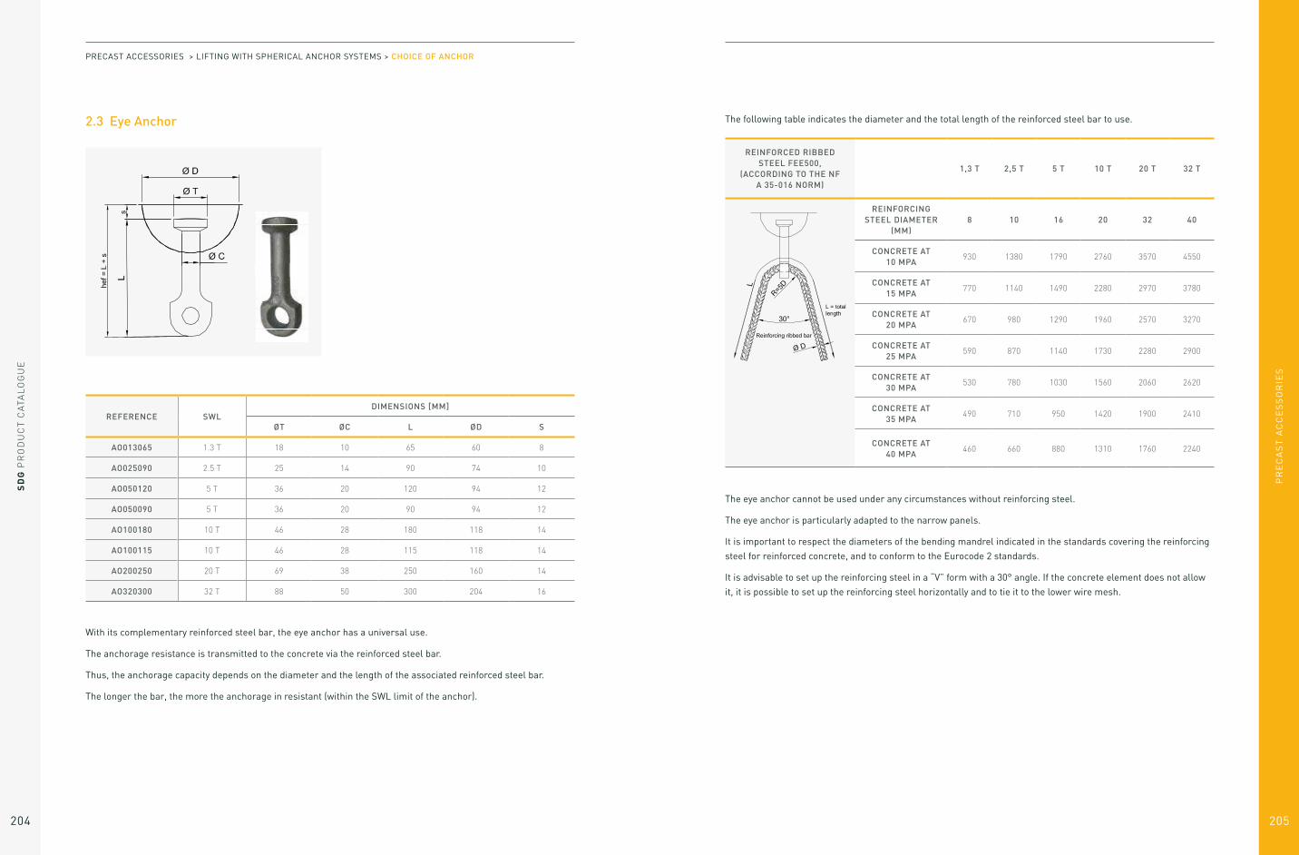
PR
EC
AS
T A
CC
ES
SO
RIE
S
SD
G P
RO
DU
CT
CA
TAL
OG
UE
204 205
2.3 Eye Anchor
REFERENCE SWLDIMENSIONS [MM]
ØT ØC L ØD S
AO013065 1.3 T 18 10 65 60 8
AO025090 2.5 T 25 14 90 74 10
AO050120 5 T 36 20 120 94 12
AO050090 5 T 36 20 90 94 12
AO100180 10 T 46 28 180 118 14
AO100115 10 T 46 28 115 118 14
AO200250 20 T 69 38 250 160 14
AO320300 32 T 88 50 300 204 16
With its complementary reinforced steel bar, the eye anchor has a universal use.
The anchorage resistance is transmitted to the concrete via the reinforced steel bar.
Thus, the anchorage capacity depends on the diameter and the length of the associated reinforced steel bar.
The longer the bar, the more the anchorage in resistant (within the SWL limit of the anchor).
PRECAST ACCESSORIES > LIFTING WITH SPHERICAL ANCHOR SYSTEMS > CHOICE OF ANCHOR
The following table indicates the diameter and the total length of the reinforced steel bar to use.
REINFORCED RIBBED STEEL FEE500,
(ACCORDING TO THE NF A 35-016 NORM)
1,3 T 2,5 T 5 T 10 T 20 T 32 T
REINFORCING STEEL DIAMETER
(MM)8 10 16 20 32 40
CONCRETE AT 10 MPA
930 1380 1790 2760 3570 4550
CONCRETE AT 15 MPA
770 1140 1490 2280 2970 3780
CONCRETE AT 20 MPA
670 980 1290 1960 2570 3270
CONCRETE AT 25 MPA
590 870 1140 1730 2280 2900
CONCRETE AT 30 MPA
530 780 1030 1560 2060 2620
CONCRETE AT 35 MPA
490 710 950 1420 1900 2410
CONCRETE AT 40 MPA
460 660 880 1310 1760 2240
The eye anchor cannot be used under any circumstances without reinforcing steel.
The eye anchor is particularly adapted to the narrow panels.
It is important to respect the diameters of the bending mandrel indicated in the standards covering the reinforcing
steel for reinforced concrete, and to conform to the Eurocode 2 standards.
It is advisable to set up the reinforcing steel in a “V” form with a 30° angle. If the concrete element does not allow
it, it is possible to set up the reinforcing steel horizontally and to tie it to the lower wire mesh.

PR
EC
AS
T A
CC
ES
SO
RIE
S
SD
G P
RO
DU
CT
CA
TAL
OG
UE
206 207
2.4 Flat End Anchor
REFERENCE SWLDIMENSIONS [MM]
ØT ØC ØP L ØD S
AOP013050 1.3 T 18 10 22 50 60 8
AOP025065 2.5 T 25 14 35 65 74 10
AOP050080 5 T 36 20 20 80 94 12
The foot and eye anchor resistance is transmitted to the concrete via its reinforcing steel. So, the anchorage
capacity depends on the diameter and the length of the reinforcing steel. The diameters and lengths of the
reinforcing steels are the same than those used for the eye anchors.
The reinforcing steel to use is the same than the one used for the eye anchor with the same SWL. (Please check
the paragraph 2.3).
The foot and eye anchor cannot under any circumstances be used without reinforcing steel.
Smaller than the eye anchor, the foot and eye anchor allows the setting up of an anchorage in narrow elements.
It is important to respect the diameters of the bending mandrel indicated in the standards covering the reinforcing
steel for reinforced concrete, and to conform to the Eurocode 2 standards.
PRECAST ACCESSORIES > LIFTING WITH SPHERICAL ANCHOR SYSTEMS > CHOICE OF ANCHOR
2.5 Rebar Anchor
REFERENCE SWLDIMENSIONS [MM]
ØT ØC L ØD S
AA020400 2.0 T 25 14 400 74 10
AA025400 2.5 T 25 14 400 74 10
AA025520 2.5 T 25 14 520 74 10
AA040510 4 T 36 20 510 94 12
AA040720 4 T 36 20 720 94 12
AA0401150 4 T 36 20 1150 94 12
AA050580 5 T 36 20 580 94 12
AA050900 5 T 36 20 900 94 12
AA075750 7.5 T 46 25 750 118 14
AA0751150 7.5 T 46 25 1150 118 14
AA100870 10 T 46 28 870 118 14
AA1001300 10 T 46 28 1300 118 14
AA1501080 10 T 69 32 1080 160 14

PR
EC
AS
T A
CC
ES
SO
RIE
S
SD
G P
RO
DU
CT
CA
TAL
OG
UE
208 209
The anchorage resistance is transmitted to the
concrete via the reinforcing steel of the anchor’s body.
REFERENCE LOAD(TONS)
LENGTH(MM)
INNER WALL THICKNESS
(MM)
CONCRETE RESISTANCE FCK (MPA)
10 15 20 25 30 35 40
AA020400 2 400 98 1.70 2.00 2.00 2.00 2.00 2.00 2.00
AA020400 2 400 70 1.40 1.84 2.00 2.00 2.00 2.00 2.00
AA025400 2.5 400 98 1.70 2.23 2.50 2.50 2.50 2.50 2.50
AA025400 2.5 400 70 1.40 1.84 2.22 2.50 2.50 2.50 2.50
AA025520 2.5 520 98 2.26 2.50 2.50 2.50 2.50 2.50 2.50
AA025520 2.5 520 70 1.86 2.44 2.50 2.50 2.50 2.50 2.50
AA040510 4 510 140 3.10 4.00 4.00 4.00 4.00 4.00 4.00
AA040510 4 510 100 2.55 3.35 4.00 4.00 4.00 4.00 4.00
AA040720 4 720 140 4.00 4.00 4.00 4.00 4.00 4.00 4.00
AA040720 4 720 100 3.71 4.00 4.00 4.00 4.00 4.00 4.00
AA0401150 4 1150 140 4.00 4.00 4.00 4.00 4.00 4.00 4.00
AA0401150 4 1150 100 4.00 4.00 4.00 4.00 4.00 4.00 4.00
AA050580 5 580 140 3.57 4.68 5.00 5.00 5.00 5.00 5.00
AA050580 5 580 100 2.94 3.85 4.67 5.00 5.00 5.00 5.00
AA050900 5 900 140 5.00 5.00 5.00 5.00 5.00 5.00 5.00
AA050900 5 900 100 4.70 5.00 5.00 5.00 5.00 5.00 5.00
AA075750 7.5 750 175 5.78 7.50 7.50 7.50 7.50 7.50 7.50
AA075750 7.5 750 125 4.76 6.24 7.50 7.50 7.50 7.50 7.50
AA0751150 7.5 1150 175 7.50 7.50 7.50 7.50 7.50 7.50 7.50
AA0751150 7.5 1150 125 7.50 7.50 7.50 7.50 7.50 7.50 7.50
AA100870 10 870 196 7.60 9.96 10.00 10.00 10.00 10.00 10.00
AA100870 10 870 140 6.26 8.20 9.94 10.00 10.00 10.00 10.00
AA1001300 10 1300 196 10.00 10.00 10.00 10.00 10.00 10.00 10.00
AA1001300 10 1300 140 9.58 10.00 10.00 10.00 10.00 10.00 10.00
AA1501080 15 1080 224 10.71 14.04 15.00 15.00 15.00 15.00 15.00
AA1501080 15 1080 160 8.82 11.56 14.01 15.00 15.00 15.00 15.00
Safety Working Load (SWL) in Tons.
PRECAST ACCESSORIES > LIFTING WITH SPHERICAL ANCHOR SYSTEMS > CHOICE OF ANCHOR
2.6 Plate Anchor
REFERENCE SWLDIMENSIONS [MM]
ØT ØC L A x B x E ØD S
AS025055 2.5 T 25 14 55 70x70x6 74 10
AS025120 2.5 T 25 14 120 70x70x6 74 10
AS050065 5 T 36 20 65 90x90x8 94 12
AS050095 5 T 36 20 95 90x90x8 94 12
AS100115 10 T 46 28 115 90x90x10 118 12
The plate anchor is well adapted for thin elements.
It must be used with the reinforcing steel bars specified in the table here after.
The plate of the anchor and the additional reinforcing steel must be placed under the upper wire mesh and tied to
the lower wire mesh
When loading, the concrete resistance must be at least at 15 MPa.
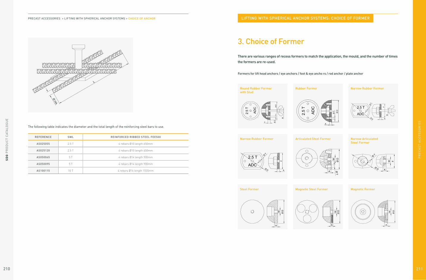
SD
G P
RO
DU
CT
CA
TAL
OG
UE
210
PR
EC
AS
T A
CC
ES
SO
RIE
S
211
REFERENCE SWL REINFORCED RIBBED STEEL FEE500
AS025055 2.5 T 4 rebars Ø10 length 650mm
AS025120 2.5 T 4 rebars Ø10 length 650mm
AS050065 5 T 4 rebars Ø14 length 900mm
AS050095 5 T 4 rebars Ø14 length 900mm
AS100115 10 T 4 rebars Ø16 length 1520mm
The following table indicates the diameter and the total length of the reinforcing steel bars to use.
PRECAST ACCESSORIES > LIFTING WITH SPHERICAL ANCHOR SYSTEMS > CHOICE OF ANCHOR
3. Choice of Former
There are various ranges of recess formers to match the application, the mould, and the number of times the formers are re-used.
Formers for lift head anchors / eye anchors / foot & eye ancho rs / rod anchor / plate anchor
Round Rubber Former with Stud
Narrow Rubber Former
Steel Former
Rubber Former
Articulated Steel Former
Magnetic Steel Former
Narrow Rubber Former
Narrow Articulated Steel Former
Magnetic Former
LIFTING WITH SPHERICAL ANCHOR SYSTEMS: CHOICE OF FORMER

PR
EC
AS
T A
CC
ES
SO
RIE
S
SD
G P
RO
DU
CT
CA
TAL
OG
UE
212 213
Formers for double head anchors
Tightening Former
Internal Magnetic Former
Magnetic Tightening Former
Internal and External Magnetic Former
PRECAST ACCESSORIES > LIFTING WITH SPHERICAL ANCHOR SYSTEMS > CHOICE OF FORMER
3.1 Formers for Lift Head Anchors, Eeye Anchors, and Foot & Eye Anchors
Complete rubber former (ref REC) (With fixing set ref EF) AND
rubber former (ref RE) (Without fixing set)
REFERENCEWITH FIXING SET
REFERENCEWITHOUT FIXING SET
LOAD COLOURDIMENSIONS (MM)
ØD ØT A M
REC013 RE013 1.3 T Blue 60 6,5 9 M8
REC025 RE025 2.5 T Yellow 74 6,5 13 M10
REC050 RE050 5 T Blue 94 8,5 15,5 M10
REC075 RE075 7.5 T Red 118 10,5 18 M12
REC100 RE100 10 T Yellow 118 10,5 18 M12
REC150 RE150 15 T Grey 160 10,5 19 M12
REC200 RE200 20 T Black 160 10,5 19 M12
REC320 RE320 32 T Black 204 10,5 19 M12
This is the most common former range. Made of flexible elastomer, it can be used up to 30 or 40 times in normal
conditions of use.
The complete rubber former (ref REC) is composed of two parts: the rubber former (ref RE) and the fixing set (ref EF).

PR
EC
AS
T A
CC
ES
SO
RIE
S
SD
G P
RO
DU
CT
CA
TAL
OG
UE
214 215
Complete narrow rubber former (ref REC) (With fixing set ref EF) AND
Narrow rubber former (ref RE) (Without fixing set)
REFERENCEWITH FIXING SET
REFERENCEWITHOUT FIXING SET
LOAD COLOURDIMENSIONS (MM)
ØD ØT A M F
REC013 RE013 1.3 T Black 60 6,5 9 M8 43
REC025 RE025 2.5 T Black 74 6,5 13 M10 53
REC050 RE050 5 T Black 94 8,5 15,5 M10 69
REC100 RE100 10 T Black 118 10,5 18 M12 85
REC200 RE200 20 T Black 160 10,5 19 M12 124
It is the narrow version of the rubber former.
The complete narrow rubber former (ref REEC) is composed of 2 parts: the narrow rubber former (ref REE) and the
fixing set (ref EF).
PRECAST ACCESSORIES > LIFTING WITH SPHERICAL ANCHOR SYSTEMS > CHOICE OF FORMER
Articulated steel former (ref RAA)
Narrow articulated steel former (ref RAAE)
REFERENCE LOADDIMENSIONS (MM)
ØD ØT A M
RAA013 1.3 T 60 7 10 M10
RAA025 2.5 T 74 7 10 M10
RAA050 5 T 94 10 10 M12
RAA100 10 T 118 10 10 M12
REFERENCE LOADDIMENSIONS (MM)
ØD ØT A M F
RAAE013 1.3 T 60 7 10 M12 42
RAAE025 2.5 T 74 7 10 M10 48
Its shape is the same as the rubber former. Made out
of steel, it can be re-used indefinitely.
Its shape is the same as the narrow rubber former.
Made out of steel, it can be re-used indefinitely.

PR
EC
AS
T A
CC
ES
SO
RIE
S
SD
G P
RO
DU
CT
CA
TAL
OG
UE
216 217
Steel former (ref RA)
Magnetic steel former (ref RAM)
REFERENCE LOADDIMENSIONS (MM)
ØD A M
RA013 1.3 T 60 10 M10
RA025 2.5 T 74 10 M10
RA050 5 T 94 10 M12
RA100 10 T 118 10 M12
REFERENCE LOADMAGNETISMINSTALLED
DIMENSIONS (MM)
ØD A M
RAM013 1.3 T 60 8 M8
RAM025 2.5 T 74 10 M12
RAM050 5 T 94 12 M12
RAM100 10 T 118 14 M12
This former is suitable for welding or screwing onto the
mould. It must be used with a rubber ring (ref BC) to
retain the anchor.
This former is to be used on metallic moulds. It must be
used with a rubber ring (ref BC) to retain the anchor.
PRECAST ACCESSORIES > LIFTING WITH SPHERICAL ANCHOR SYSTEMS > CHOICE OF FORMER
Magnetic FormerThis former is to be used on metallic moulds. It must be
used with a rubber ring (ref BC) to retain the anchor.
REFERENCE LOADMAGNETISMINSTALLED
DIMENSIONS (MM)
ØD A M
RM013 1.3 T 60 kg 60 6 M8
RM025 2.5 T 75 kg 74 9 M10
RM050 5 T 100 kg 94 12 M10
RM100 10 T 150 kg 118 12 M10

PR
EC
AS
T A
CC
ES
SO
RIE
S
SD
G P
RO
DU
CT
CA
TAL
OG
UE
218 219
3.2 Additional Accessories for Formers
Rubber ring (ref BC)
Fixing set (ref EF)
REFERENCE LOADDIMENSIONS (MM)
ØD Ød A
BC013 1.3 T 22 10 11
BC025 2.5 T 32 14 12
BC050 5 T 39 20 14
BC100 10 T 49 28 20
REFERENCE LOADDIMENSIONS (MM)
L M
EF013 1.3 T 80 M8
EF025 2.5 T 80 M10
EF050 5 T 100 M10
EF100 7.5 – 10 T 100 M12
EF200 15 – 20 T 100 M12
PRECAST ACCESSORIES > LIFTING WITH SPHERICAL ANCHOR SYSTEMS > CHOICE OF FORMER
Threaded plate (ref PT)
REFERENCE LOADDIMENSIONS (MM)
M
PT013 1.3 T M8
PT025 2.5 T M10
PT050 5 T M10
PT100 7.5 – 10 T M12
PT200 15 – 20 T M12

PR
EC
AS
T A
CC
ES
SO
RIE
S
SD
G P
RO
DU
CT
CA
TAL
OG
UE
220 221
3.3 Formers for Double Head Anchors
Tightening former (ref RC)
Magnetic tightening former (ref RCM)
REFERENCE LOADDIMENSIONS (MM)
ØD A M
RC013 1.3 T 60 9 M8
RC025 2.5 T 74 11 M10
RC050 5 T 94 14 M10
This former is made of elastomer. The double head
anchor is forced lightly into the former held in place by
pressure on the anchor head and collar.
The former is screwed into the mould.
It is the magnetic version of the tightening former.
This former is made of polyurethane. The double head
anchor is forced lightly into the former held in place by
pressure on the anchor head and collar.
The former is held onto a metallic mould by its magnet.
REFERENCE LOADMAGNETISMINSTALLED
DIMENSIONS (MM)
ØD A M
RCM013 1.3 T 60 kg 60 9 M8
RCM025 2.5 T 60 kg 74 11 M10
RCM050 5 T 100 kg 94 14 M10
PRECAST ACCESSORIES > LIFTING WITH SPHERICAL ANCHOR SYSTEMS > CHOICE OF FORMER
Internal and external magnetic former (ref RIM)It is the magnetic version of the internal magnetic former.
The former is held onto a metallic mould by its magnet.
REFERENCE LOADMAGNETISMINSTALLED
DIMENSIONS (MM)
ØD A M
RIM013 1.3 T 75 kg 60 9 M8
RIM025 2.5 T 75 kg 74 11 M10
Internal magnetic former (ref RI)
REFERENCE LOADDIMENSIONS (MM)
ØD A M
RC013 1.3 T 60 9 M8
RC025 2.5 T 74 11 M10
RC050 5 T 94 14 M10
This former is made of steel. The double head anchor
is set up into the former and held by a light internal
magnet, allowing a rapid and easy removal from the
mould.
The former can be screwed or welded onto the mould.

PR
EC
AS
T A
CC
ES
SO
RIE
S
223
SD
G P
RO
DU
CT
CA
TAL
OG
UE
222
4. Lift Head Shackle
The lift head shackle must be chosen to match the anchor load. Under no circumstances should a lift head shackle
be used with a different capacity to that of the anchor, even if the load capacity of the lift head shackle is superior
to the load capacity of the anchor.
REFERENCE SWLDIMENSIONS (MM)
A B C D E L
AN013 1.3 T 70 46 74 20 12 190
AN025 2.5 T 85 58 88 25 14 235
AN050 5 T 88 70 118 37 16 280
AN100 10 T 112 84 160 50 26 390
AN200 20 T 150 118 186 75 30 500
AN320 32 T 189 175 269 100 45
4.1 Quality system
The dimensions of the Lift Head Shackle are 100% quality checked.
For each batch, destructive testing is carried out to ensure quality standards are maintained.
Each Lift Head Shackle is provided with a CE declaration of conformity. On the back of this declaration, the safety
and usage and conditions are stated.
4.2 Periodic control
Whatever the frequency of use, each Lift Head Shackle must be tested once a year by a competent person. Any
physical abnormality, deformation, any sign of welding, must lead to the immediate destruction of the shackle.
The Lift Head Shackles cannot be repaired.
The points to test are:
1. Visual test
– Absence of permanent deformation (elongated or twisted handle)
– Absence of welding signs (except the original weld).
2. Test of the correct hinge operation between the nut and the handle
3. Test of the nut lips spacing (using a gauge or a caliper) on the whole of its length:
4.3 Remote decoupling
A remote decoupling system can be provided to decouple the lift head shackle from the anchors when access to
the anchor points is difficult.
REFERENCE SWLMINIMAL
DIMENSIONMAXIMAL
DIMENSION
AN013 1.3 T 10.5 13.0
AN025 2.5 T 15.0 17.5
AN050 5 T 20.5 23.5
AN100 10 T 28.5 32.0
AN200 20 T 40.5 45.0
AN320 32 T 51.0 58.0
LIFTING WITH SPHERICAL ANCHOR SYSTEMS: LIFT HEAD SHACKLE
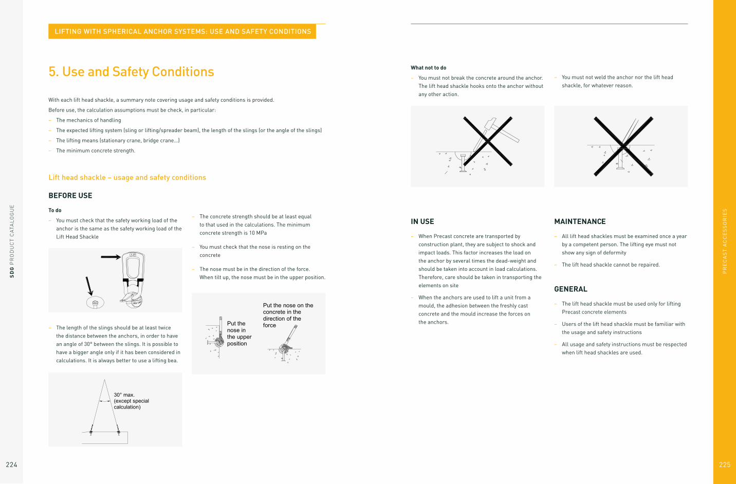
PR
EC
AS
T A
CC
ES
SO
RIE
S
225
SD
G P
RO
DU
CT
CA
TAL
OG
UE
224
5. Use and Safety Conditions
With each lift head shackle, a summary note covering usage and safety conditions is provided.
Before use, the calculation assumptions must be check, in particular:
– The mechanics of handling
– The expected lifting system (sling or lifting/spreader beam), the length of the slings (or the angle of the slings)
– The lifting means (stationary crane, bridge crane…)
– The minimum concrete strength.
BEFORE USE
To do
– You must check that the safety working load of the
anchor is the same as the safety working load of the
Lift Head Shackle
What not to do
– You must not break the concrete around the anchor.
The lift head shackle hooks onto the anchor without
any other action.
– You must not weld the anchor nor the lift head
shackle, for whatever reason.
– The length of the slings should be at least twice
the distance between the anchors, in order to have
an angle of 30° between the slings. It is possible to
have a bigger angle only if it has been considered in
calculations. It is always better to use a lifting bea.
– The concrete strength should be at least equal
to that used in the calculations. The minimum
concrete strength is 10 MPa
– You must check that the nose is resting on the
concrete
– The nose must be in the direction of the force.
When tilt up, the nose must be in the upper position.
Lift head shackle – usage and safety conditions
MAINTENANCE
– All lift head shackles must be examined once a year
by a competent person. The lifting eye must not
show any sign of deformity
– The lift head shackle cannot be repaired.
GENERAL
– The lift head shackle must be used only for lifting
Precast concrete elements
– Users of the lift head shackle must be familiar with
the usage and safety instructions
– All usage and safety instructions must be respected
when lift head shackles are used.
IN USE
– When Precast concrete are transported by
construction plant, they are subject to shock and
impact loads. This factor increases the load on
the anchor by several times the dead-weight and
should be taken into account in load calculations.
Therefore, care should be taken in transporting the
elements on site
– When the anchors are used to lift a unit from a
mould, the adhesion between the freshly cast
concrete and the mould increase the forces on
the anchors.
LIFTING WITH SPHERICAL ANCHOR SYSTEMS: USE AND SAFETY CONDITIONS

PR
EC
AS
T A
CC
ES
SO
RIE
S
227
SD
G P
RO
DU
CT
CA
TAL
OG
UE
226
Precast Plastic Spacers
Gate Post Spacers
Sill Spacers
Flag Spacers
PRODUCT CODE DESCRIPTION SIZE
PLA080 Fence Post Spacer 75 x 75 1000 / Bag
PLA082 Fence Post Spacer 87 x 87 1000 / Bag
PLA083 Fence Post Spacer 100 x 100 1000 / Bag
PLA084 Fence Post Spacer 112 x 112 1000 / Bag
PLA085 Fence Post Spacer 125 x 125 1000 / Bag
PRODUCT CODE DESCRIPTION SIZE
PLA086 Gate Post Spacer 7 x 7 500 / Bag
PRODUCT CODE DESCRIPTION SIZE
PLA175 Plastic Sill Spacer 500 / Bag
PRODUCT CODE DESCRIPTION SIZE
PLA070 Flag Spacer Double 1000 / Bag
PLA075 Flag Spacers 370mm 2000 / Bag
SDG Spacers
Panel Packers
Cattle Slot Spacers
PRODUCT CODE DESCRIPTION SIZE
PLA163 SDG 200 1000 / Bag
PLA164 SDG 300 1000 / Bag
PRODUCT CODE DESCRIPTION SIZE
PLA105 Panel Packers 200 / Bag
PRODUCT CODE DESCRIPTION SIZE
PLA001 Bar Spacer 6x3 1000 / Bag
PLA002 Bar Spacer 7x4 500 / Bag
PRECAST PLASTIC ACCESSORIES
Fence Post Spacers
Plastic Shim Allow for alignment and levelling of heavy section steel
plate and pre-cast concrete sections.
PRODUCT CODE PRODUCT DESCRIPTION PRODUCT SIZE
PLA170 Plastic Shim 2 mm: 70 x70 mm 125 per Bag
PLA171 Plastic Shim 3 mm: 70 x 70 mm 125 per Bag
PLA172 Plastic Shim 5 mm: 70 x 70 mm 125 per Bag
PLA173 Plastic Shim 7 mm: 70 x 70 mm 125 per Bag
PLA174 Plastic Shim 9 mm: 70 x 70 mm 125 per Bag
PLA174B Plastic Shim 20 mm: 70 x 70 mm 50 per Bag

SD
G P
RO
DU
CT
CA
TAL
OG
UE
228
PR
EC
AS
T A
CC
ES
SO
RIE
S
229
Concrete End Caps
PRODUCT CODE DESCRIPTION SIZE
PLA069 End Caps 7mm 5000 / Bag
PLA071 End Caps 6mm 8000 / Bag
HD End Caps
PRODUCT CODE DESCRIPTION SIZE
PLA051 HD End Cap 25mm / 4-8mm 500 / Bag
PLA051B HD End Cap 25mm / 10-16mm 500 / Bag
PLA051A HD End Cap 20mm / 4-8mm 2500 / Bag
PLA052 HD End Cap 30mm / 10-16mm 250 / Bag
PRECAST ACCESSORIES > PRECAST PLASTIC ACCESSORIES CONCRETE STRUCTURAL FIBRES
Barchip 48
Synthetic fire concrete reinforcement
BarChip 48 is a high performance structural synthetic
fibre concrete reinforcement, optimised for pavements,
industrial floors and precast elements. Work with
BarChip and together we’ll unlock the full potential of
your concrete mix.
Benefits:
– Comprehensive design and technical support
– Redistributes load – increased ductility / toughness
– Eliminates corrosion – long term durability
– Eliminates set-up of steel mesh
– Improves precast production speeds up to 50%
– Increases abrasion and impact protection
– 70% reduction in carbon footprint compared to steel
– Safer and lighter to handle than steel
– Reduced wear on concrete pumps and hoses.
CapsProvide formwork cover and prevent rust staining.

SD
G P
RO
DU
CT
CA
TAL
OG
UE
368 369
Visit our website for further product information or call
our sales team to speak to one of our expert advisors.
WEARESDG.COM
+44 (0) 28 3752 8999
Still looking for something?

SD
G P
RO
DU
CT
CA
TAL
OG
UE
COMPANY REGISTRATION NUMBER: NI026782 VAT NUMBER: GB 575 4411 34

SD
G P
RO
DU
CT
CA
TAL
OG
UE
372
Get in touch
HEAD OFFICE
21 Tullygoonigan Industrial EstateMoy RoadArmaghBT61 8DR
Tel: +44 (0) 28 3752 8999
MONAGHAN OFFICE
CornacrieveEmyvaleMonaghanHY18 XY 46
Tel: + 353 (47) 87 295
wearesdg.com Email: [email protected]