
Catalogo cmw soldadura
58
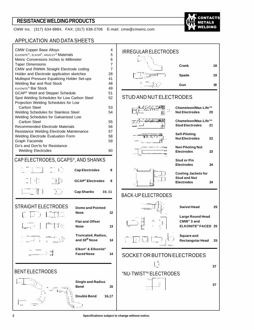
CONTACTS METALS WELDING 2 Specifications subject to change without notice. APPLICATION AND DATA SHEETS CMW Copper Base Alloys 4 ELKONITE ® , ELKON ® , ANVILOY ® Materials 5 Metric Conversions Inches to Millimeter 6 Taper Dimensions 7 CMW and RWMA Straight Electrode coding 7 Holder and Electrode application sketches 28 Multispot Pressure Equalizing Holder Set-ups 41 Welding Bar and Rod Stock 48 ELKONITE ® Bar Stock 49 GCAP ® Weld and Stepper Schedule 51 Spot Welding Schedules for Low Carbon Steel 52 Projection Welding Schedules for Low Carbon Steel 53 Welding Schedules for Stainless Steel 54 Welding Schedules for Galvanized Low Carbon Steel 55 Recommended Electrode Materials 56 Resistance Welding Electrode Maintenance 57 Welding Electrode Evaluation Form 58 Graph Facsimile 59 Do’s and Don’ts for Resistance Welding Electrodes 60 37 37 SOCKET OR BUTTON ELECTRODES STRAIGHT ELECTRODES BENT ELECTRODES Crank 18 Spade 19 Gun 19 IRREGULAR ELECTRODES STUD AND NUT ELECTRODES Chameleon/Max-Life™ Nut Electrodes 20 Chameleon/Max-Life™ Stud Electrodes 21 Self-Piloting Nut Electrodes 22 Non Piloting Nut Electrodes 23 Stud or Pin Electrodes 24 Cooling Jackets for Stud and Nut Electrodes 24 BACK-UP ELECTRODES Swivel Head 25 Large Round Head CMW ® 3 and ELKONITE ® FACED 25 Square and Rectangular Head 25 Dome and Pointed Nose 12 Flat and Offset Nose 13 Truncated, Radius, and 30 o Nose 14 Elkon ® & Elkonite ® Faced Nose 14 Single and Radius Bend 15 Double Bend 16,17 “NU-TWIST” ® ELECTRODES CMW Inc. (317) 634-8884, FAX: (317) 638-2706 E-mail: [email protected] Cap Electrodes 8 GCAP ® Electrodes 9 Cap Shanks 10, 11 RESISTANCE WELDING PRODUCTS CAP ELECTRODES, GCAPS ® , AND SHANKS
-
Upload
oscar-moro -
Category
Documents
-
view
133 -
download
12
Transcript of Catalogo cmw soldadura
��������
�����
����
2 Specifications subject to change without notice.
APPLICATION AND DATA SHEETS
CMW Copper Base Alloys 4ELKONITE®, ELKON®, ANVILOY® Materials 5Metric Conversions Inches to Millimeter 6Taper Dimensions 7CMW and RWMA Straight Electrode coding 7Holder and Electrode application sketches 28Multispot Pressure Equalizing Holder Set-ups 41Welding Bar and Rod Stock 48ELKONITE® Bar Stock 49GCAP® Weld and Stepper Schedule 51Spot Welding Schedules for Low Carbon Steel 52Projection Welding Schedules for Low
Carbon Steel 53Welding Schedules for Stainless Steel 54Welding Schedules for Galvanized Low
Carbon Steel 55Recommended Electrode Materials 56Resistance Welding Electrode Maintenance 57Welding Electrode Evaluation Form 58Graph Facsimile 59Do’s and Don’ts for Resistance
Welding Electrodes 60
37
37
SOCKET OR BUTTON ELECTRODES
STRAIGHT ELECTRODES
BENT ELECTRODES
Crank 18
Spade 19
Gun 19
IRREGULAR ELECTRODES
STUD AND NUT ELECTRODES
Chameleon/Max-Life™Nut Electrodes 20
Chameleon/Max-Life™Stud Electrodes 21
Self-PilotingNut Electrodes 22
Non Piloting NutElectrodes 23
Stud or PinElectrodes 24
Cooling Jackets forStud and NutElectrodes 24
BACK-UP ELECTRODES
Swivel Head 25
Large Round HeadCMW® 3 andELKONITE® FACED 25
Square andRectangular Head 25
Dome and PointedNose 12
Flat and OffsetNose 13
Truncated, Radius,and 30o Nose 14
Elkon® & Elkonite®
Faced Nose 14
Single and RadiusBend 15
Double Bend 16,17
“NU-TWIST”® ELECTRODES
CMW Inc. (317) 634-8884, FAX: (317) 638-2706 E-mail: [email protected]
Cap Electrodes 8
GCAP® Electrodes 9
Cap Shanks 10, 11
RESISTANCE WELDING PRODUCTS
CAP ELECTRODES, GCAPS®, AND SHANKS
THREADED ELECTRODES
26
ELECTRODE HOLDERS
HOLDER TO ELECTRODE ADAPTERS
Non Ejector 27
Ejector 30
AssemblyExamples 29,30,31,33
Universal 35
100 Series StraightNon Ejector 29
200 Series StraightEjector 30
300 SeriesPremium StraightEjector 31
400 SeriesLight Non-EjectorOffset 32
500 SeriesHeavy Duty EjectorOffset 33
600 Series UniversalHolders 34
600 SeriesUniversal HolderComponents 35
Platen MountedHolders 43
800 Series“Nu-Twist”®
Surface andThreaded Adapters 36
Hydraulic EqualizingAdapters for800 Series 38
Dual MountedHydraulic“Nu-Twist”®
Assemblies 39
900 Series LightUniversal Holdersfor SocketElectrodes 42
950 Series PaddleHolders for SocketElectrodes 42
LOW INERTIA HOLDERS
CONTACTORS
ACCESSORIES
Cap ElectrodeExtractor Fork 45
Reamers, HoseConnectors, andHose Clamps 45
PneumaticElectrode Dresserand Cutters 46,47
Hand ElectrodeDressers 47
Force Gauge 50
MULTISPOT ADAPTERS FOR AIR ORHYDRAULIC PISTONS
ORDER BY CMW PART NUMBER ONLY 3
1200 SeriesMulti-Spot Adapters 44
Welder Contactors 44
1100 SeriesAdjust-A-PressureLow Inertia Holders 40
1150 SeriesAdjust-A-PressureAdapters 40
...........
........
CMW Inc. (317) 634-8884, FAX: (317) 638-2706 E-mail: [email protected]
��������
�����
����
COPPER BASE ALLOYS
Long electrode life is of paramount importance to theuser of resistance welding equipment. Selection of theproper CMW alloy or combination of alloys will help togive improved weld strength and electrode life.
CMW electrodes are fabricated from alloys selectedfrom the results of laboratory and practical field tests.For special problems, CMW engineers will make recom-mendations based on their years of experience.
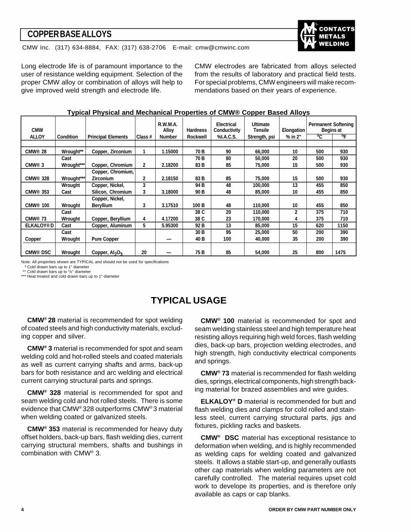
Typical Physical and Mechanical Properties of CMW® Copper Based Alloys
CMW Alloy Hardness Conductivity Tensile Elongation Begins atALLOY Condition Principal Elements Class # Number Rockwell %I.A.C.S. Strength, psi % in 2" oC oF
CMW® 28 Wrought** Copper, Zirconium 1 1.15000 70 B 90 66,000 10 500 930Cast 70 B 80 50,000 20 500 930
CMW® 3 Wrought*** Copper, Chromium 2 2.18200 83 B 85 75,000 15 500 930Copper, Chromium,
CMW® 328 Wrought*** Zirconium 2 2.18150 83 B 85 75,000 15 500 930Wrought Copper, Nickel, 3 94 B 48 100,000 13 455 850
CMW® 353 Cast Silicon, Chromium 3 3.18000 90 B 48 85,000 10 455 850Copper, Nickel,
CMW® 100 Wrought Beryllium 3 3.17510 100 B 48 110,000 10 455 850Cast 38 C 20 110,000 2 375 710
CMW® 73 Wrought Copper, Beryllium 4 4.17200 38 C 23 170,000 4 375 710ELKALOY® D Cast Copper, Aluminum 5 5.95300 92 B 13 85,000 15 620 1150
Cast 30 B 95 25,000 50 200 390Copper Wrought Pure Copper — 40 B 100 40,000 35 200 390
CMW® DSC Wrought Copper, Al2O3 20 — 75 B 85 54,000 25 800 1475
Note: All properties shown are TYPICAL and should not be used for specifications * Cold drawn bars up to 1" diameter** Cold drawn bars up to 5/8" diameter
*** Heat treated and cold drawn bars up to 1" diameter
TYPICAL USAGE
CMW® 28 material is recommended for spot weldingof coated steels and high conductivity materials, exclud-ing copper and silver.
CMW® 3 material is recommended for spot and seamwelding cold and hot-rolled steels and coated materialsas well as current carrying shafts and arms, back-upbars for both resistance and arc welding and electricalcurrent carrying structural parts and springs.
CMW® 328 material is recommended for spot andseam welding cold and hot rolled steels. There is someevidence that CMW® 328 outperforms CMW® 3 materialwhen welding coated or galvanized steels.
CMW® 353 material is recommended for heavy dutyoffset holders, back-up bars, flash welding dies, currentcarrying structural members, shafts and bushings incombination with CMW® 3.
CMW® 100 material is recommended for spot andseam welding stainless steel and high temperature heatresisting alloys requiring high weld forces, flash weldingdies, back-up bars, projection welding electrodes, andhigh strength, high conductivity electrical componentsand springs.
CMW® 73 material is recommended for flash weldingdies, springs, electrical components, high strength back-ing material for brazed assemblies and wire guides.
ELKALOY® D material is recommended for butt andflash welding dies and clamps for cold rolled and stain-less steel, current carrying structural parts, jigs andfixtures, pickling racks and baskets.
CMW® DSC material has exceptional resistance todeformation when welding, and is highly recommendedas welding caps for welding coated and galvanizedsteels. It allows a stable start-up, and generally outlastsother cap materials when welding parameters are notcarefully controlled. The material requires upset coldwork to develope its properties, and is therefore onlyavailable as caps or cap blanks.
4 ORDER BY CMW PART NUMBER ONLY
CMW Inc. (317) 634-8884, FAX: (317) 638-2706 E-mail: [email protected]
R.W.M.A. Electrical Ultimate Permanent Softening
��������
�����
����
ELKONITE® is the registered trade mark of CMWused to identify a group of metal compositions whoseelements consist basically of the refractory metalstungsten, molybdenum and tungsten carbide combinedwith copper. Combinations of these elements producedense, hard metals of superior wear resistance andstrength at elevated temperatures, coupled with goodthermal and electrical conductivity. The mechanical andphysical properties of the ELKONITE® materials makethem particularly suitable as the die inserts and facingsfor volume projection welding, flash and butt welding,
electrical upsetting, electroforging and mash weldingapplications.
ELKONITE® material is also used successfully asfacing on spot welding electrodes where heat balance ormechanical wear resistance are required. The initialpremium cost of ELKONITE® material is offset by lowerproduction cost per weld due to long die life and lesselectrode dressing time. The high stability of ELKONITE®
material insures uniform heating and prevents misalign-ment, resulting in a higher quality weld.
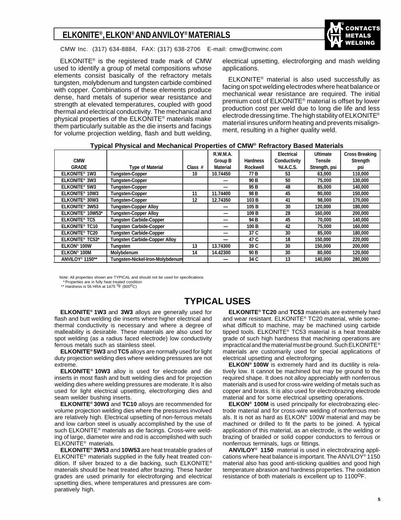
Typical Physical and Mechanical Properties of CMW® Refractory Based MaterialsR.W.M.A. Electrical Ultimate Cross Breaking
CMW Group B Hardness Conductivity Tensile StrengthGRADE Type of Material Class # Material Rockwell %I.A.C.S. Strength, psi psi
ELKONITE® 1W3 Tungsten-Copper 10 10.74450 77 B 53 63,000 110,000ELKONITE® 3W3 Tungsten-Copper — 90 B 50 75,000 130,000ELKONITE® 5W3 Tungsten-Copper — 95 B 48 85,000 140,000ELKONITE® 10W3 Tungsten-Copper 11 11.74400 98 B 45 90,000 150,000ELKONITE® 30W3 Tungsten-Copper 12 12.74350 103 B 41 98,000 170,000ELKONITE® 3W53 Tungsten-Copper Alloy — 105 B 30 120,000 180,000ELKONITE® 10W53* Tungsten-Copper Alloy — 109 B 28 160,000 200,000ELKONITE® TC5 Tungsten Carbide-Copper — 94 B 45 70,000 140,000ELKONITE® TC10 Tungsten Carbide-Copper — 100 B 42 75,000 160,000ELKONITE® TC20 Tungsten Carbide-Copper — 37 C 30 85,000 180,000ELKONITE® TC53* Tungsten Carbide-Copper Alloy — 47 C 18 150,000 220,000ELKON® 100W Tungsten 13 13.74300 39 C 30 150,000 200,000ELKON® 100M Molybdenum 14 14.42300 90 B 30 80,000 120,000ANVILOY® 1150** Tungsten-Nickel-Iron-Molybdenum — 34 C 13 140,000 280,000
Note: All properties shown are TYPICAL and should not be used for specifications * Properties are in fully heat treated condition** Hardness is 56 HRA at 1475 oF (800oC)
ELKONITE®, ELKON® AND ANVILOY® MATERIALS
TYPICAL USESELKONITE® 1W3 and 3W3 alloys are generally used for
flash and butt welding die inserts where higher electrical andthermal conductivity is necessary and where a degree ofmalleability is desirable. These materials are also used forspot welding (as a radius faced electrode) low conductivityferrous metals such as stainless steel.
ELKONITE® 5W3 and TC5 alloys are normally used for lightduty projection welding dies where welding pressures are notextreme.
ELKONITE® 10W3 alloy is used for electrode and dieinserts in most flash and butt welding dies and for projectionwelding dies where welding pressures are moderate. It is alsoused for light electrical upsetting, electroforging dies andseam welder bushing inserts.
ELKONITE® 30W3 and TC10 alloys are recommended forvolume projection welding dies where the pressures involvedare relatively high. Electrical upsetting of non-ferrous metalsand low carbon steel is usually accomplished by the use ofsuch ELKONITE® materials as die facings. Cross-wire weld-ing of large, diameter wire and rod is accomplished with suchELKONITE® materials.
ELKONITE® 3W53 and 10W53 are heat treatable grades ofELKONITE® materials supplied in the fully heat treated con-dition. If silver brazed to a die backing, such ELKONITE®
materials should be heat treated after brazing. These hardergrades are used primarily for electroforging and electricalupsetting dies, where temperatures and pressures are com-paratively high.
ELKONITE® TC20 and TC53 materials are extremely hardand wear resistant. ELKONITE® TC20 material, while some-what difficult to machine, may be machined using carbidetipped tools. ELKONITE® TC53 material is a heat treatablegrade of such high hardness that machining operations areimpractical and the material must be ground. Such ELKONITE®
materials are customarily used for special applications ofelectrical upsetting and electroforging.
ELKON® 100W is extremely hard and its ductility is rela-tively low. It cannot be machined but may be ground to therequired shape. It does not alloy appreciably with nonferrousmaterials and is used for cross-wire welding of metals such ascopper and brass. It is also used for electrobrazing electrodematerial and for some electrical upsetting operations.
ELKON® 100M is used principally for electrobrazing elec-trode material and for cross-wire welding of nonferrous met-als. It is not as hard as ELKON® 100W material and may bemachined or drilled to fit the parts to be joined. A typicalapplication of this material, as an electrode, is the welding orbrazing of braided or solid copper conductors to ferrous ornonferrous terminals, lugs or fittings.
ANVILOY® 1150 material is used in electrobrazing appli-cations where heat balance is important. The ANVILOY® 1150material also has good anti-sticking qualities and good hightemperature abrasion and hardness properties. The oxidationresistance of both materials is excellent up to 1100oF.
5
CMW Inc. (317) 634-8884, FAX: (317) 638-2706 E-mail: [email protected]
��������
�����
����
Gage Decimal Millimeter
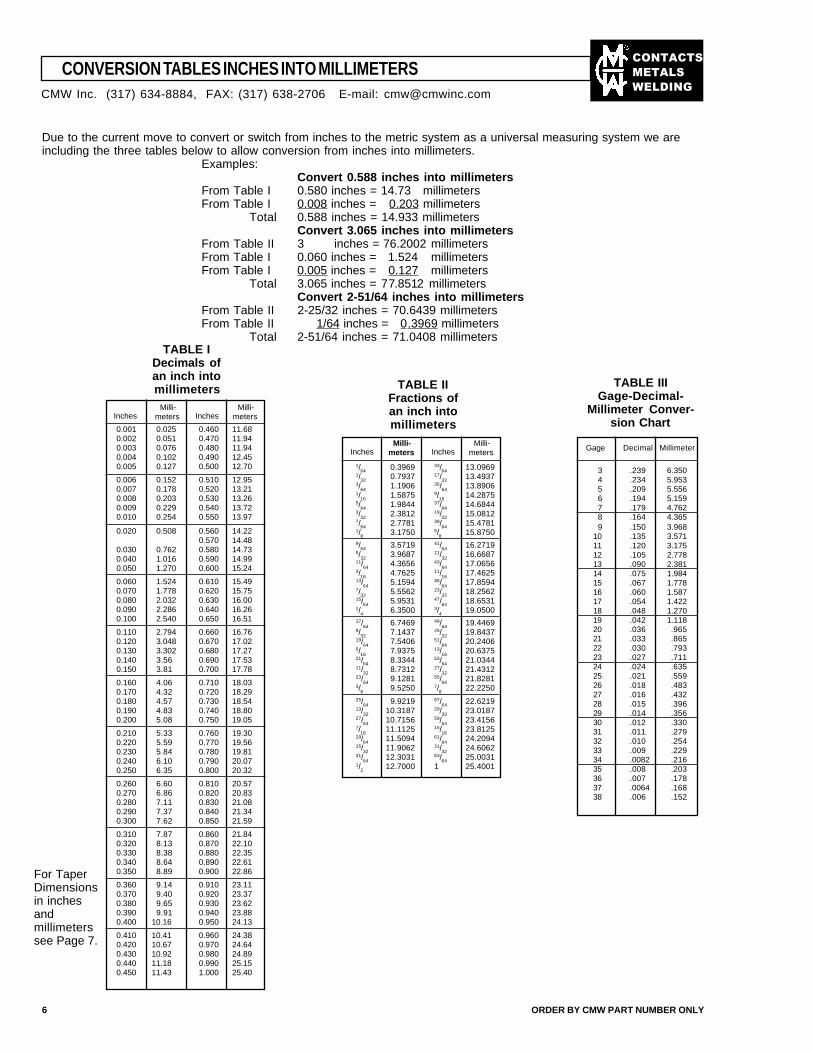
CONVERSION TABLES INCHES INTO MILLIMETERS
Due to the current move to convert or switch from inches to the metric system as a universal measuring system we areincluding the three tables below to allow conversion from inches into millimeters.
Examples:Convert 0.588 inches into millimeters
From Table I 0.580 inches = 14.73 millimetersFrom Table I 0.008 inches = 0.203 millimeters
Total 0.588 inches = 14.933 millimetersConvert 3.065 inches into millimeters
From Table II 3 inches = 76.2002 millimetersFrom Table I 0.060 inches = 1.524 millimetersFrom Table I 0.005 inches = 0.127 millimeters
Total 3.065 inches = 77.8512 millimetersConvert 2-51/64 inches into millimeters
From Table II 2-25/32 inches = 70.6439 millimetersFrom Table II 1/64 inches = 0.3969 millimeters
Total 2-51/64 inches = 71.0408 millimeters
6 ORDER BY CMW PART NUMBER ONLY
TABLE IDecimals ofan inch intomillimeters
Inches Inches Milli-meters
0.001 0.025 0.460 11.680.002 0.051 0.470 11.940.003 0.076 0.480 11.940.004 0.102 0.490 12.450.005 0.127 0.500 12.70
0.006 0.152 0.510 12.950.007 0.178 0.520 13.210.008 0.203 0.530 13.260.009 0.229 0.540 13.720.010 0.254 0.550 13.97
0.020 0.508 0.560 14.220.570 14.48
0.030 0.762 0.580 14.730.040 1.016 0.590 14.990.050 1.270 0.600 15.24
0.060 1.524 0.610 15.490.070 1.778 0.620 15.750.080 2.032 0.630 16.000.090 2.286 0.640 16.260.100 2.540 0.650 16.51
0.110 2.794 0.660 16.760.120 3.048 0.670 17.020.130 3.302 0.680 17.270.140 3.56 0.690 17.530.150 3.81 0.700 17.78
0.160 4.06 0.710 18.030.170 4.32 0.720 18.290.180 4.57 0.730 18.540.190 4.83 0.740 18.800.200 5.08 0.750 19.05
0.210 5.33 0.760 19.300.220 5.59 0.770 19.560.230 5.84 0.780 19.810.240 6.10 0.790 20.070.250 6.35 0.800 20.32
0.260 6.60 0.810 20.570.270 6.86 0.820 20.830.280 7.11 0.830 21.080.290 7.37 0.840 21.340.300 7.62 0.850 21.59
0.310 7.87 0.860 21.840.320 8.13 0.870 22.100.330 8.38 0.880 22.350.340 8.64 0.890 22.610.350 8.89 0.900 22.86
0.360 9.14 0.910 23.110.370 9.40 0.920 23.370.380 9.65 0.930 23.620.390 9.91 0.940 23.880.400 10.16 0.950 24.13
0.410 10.41 0.960 24.380.420 10.67 0.970 24.640.430 10.92 0.980 24.890.440 11.18 0.990 25.150.450 11.43 1.000 25.40
For TaperDimensionsin inchesandmillimeterssee Page 7.
Inches Inches
TABLE IIFractions ofan inch intomillimeters
1/64 0.3969 33/64 13.09691/32 0.7937 17/32 13.49373/64 1.1906 35/64 13.89061/16 1.5875 9/16 14.28755/64 1.9844 37/64 14.68443/32 2.3812 19/32 15.08127/64 2.7781 39/64 15.47811/8 3.1750 5/8 15.87509/64 3.5719 41/64 16.27195/32 3.9687 21/32 16.668711/64 4.3656 43/64 17.06563/16 4.7625 11/16 17.462513/64 5.1594 45/64 17.85947/32 5.5562 23/32 18.256215/64 5.9531 47/64 18.65311/4 6.3500 3/4 19.050017/64 6.7469 49/64 19.44699/32 7.1437 25/32 19.843719/64 7.5406 51/64 20.24065/16 7.9375 13/16 20.637521/64 8.3344 53/64 21.034411/32 8.7312 27/32 21.431223/64 9.1281 55/64 21.82813/8 9.5250 7/8 22.225025/64 9.9219 57/64 22.621913/32 10.3187 29/32 23.018727/64 10.7156 59/64 23.41567/16 11.1125 15/16 23.812529/64 11.5094 61/64 24.209415/32 11.9062 31/32 24.606231/64 12.3031 63/64 25.00311/2 12.7000 1 25.4001
3 .239 6.3504 .234 5.9535 .209 5.5566 .194 5.1597 .179 4.7628 .164 4.3659 .150 3.968
10 .135 3.57111 .120 3.17512 .105 2.77813 .090 2.38114 .075 1.98415 .067 1.77816 .060 1.58717 .054 1.42218 .048 1.27019 .042 1.11820 .036 .96521 .033 .86522 .030 .79323 .027 .71124 .024 .63525 .021 .55926 .018 .48327 .016 .43228 .015 .39629 .014 .35630 .012 .33031 .011 .27932 .010 .25433 .009 .22934 .0082 .21635 .008 .20336 .007 .17837 .0064 .16838 .006 .152
TABLE IIIGage-Decimal-
Millimeter Conver-sion Chart
CMW Inc. (317) 634-8884, FAX: (317) 638-2706 E-mail: [email protected]
Milli-meters
Milli-meters
Milli-meters
��������
�����
����
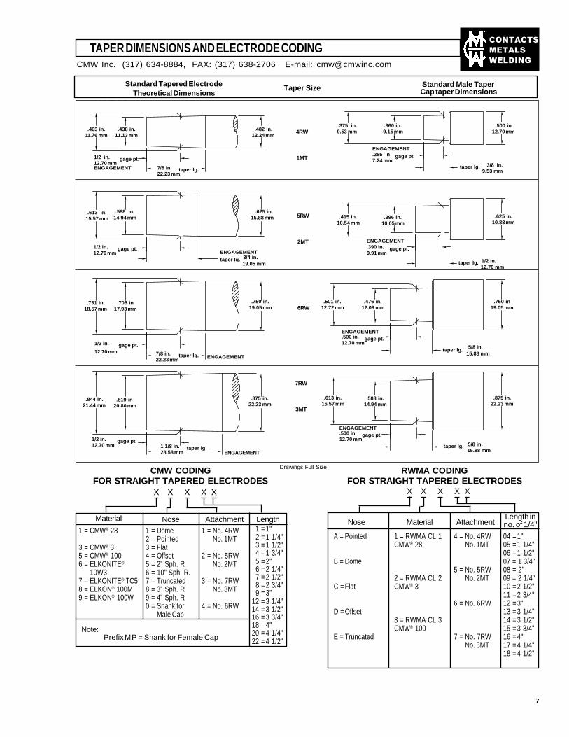
TAPER DIMENSIONS AND ELECTRODE CODING
Standard Tapered ElectrodeTheoretical Dimensions
Note:Prefix MP = Shank for Female Cap
Nose Attachment LengthMaterial Nose Material AttachmentLength inno. of 1/4"
X XXX XX XXX X
7
1 = Dome2 = Pointed3 = Flat4 = Offset5 = 2" Sph. R6 = 10" Sph. R.7 = Truncated8 = 3" Sph. R9 = 4" Sph. R0 = Shank for
Male Cap
1 = CMW® 28
3 = CMW® 35 = CMW® 1006 = ELKONITE®
10W37 = ELKONITE® TC58 = ELKON® 100M9 = ELKON® 100W
1 = No. 4RWNo. 1MT
2 = No. 5RWNo. 2MT
3 = No. 7RWNo. 3MT
4 = No. 6RW
A = Pointed
B = Dome
C = Flat
D = Offset
E = Truncated
1 = RWMA CL 1CMW® 28
2 = RWMA CL 2CMW® 3
3 = RWMA CL 3CMW® 100
4 = No. 4RWNo. 1MT
5 = No. 5RWNo. 2MT
6 = No. 6RW
7 = No. 7RWNo. 3MT
04 = 1"05 = 1 1/4"06 = 1 1/2"07 = 1 3/4"08 = 2"09 = 2 1/4"10 = 2 1/2"11 = 2 3/4"12 = 3"13 = 3 1/4"14 = 3 1/2"15 = 3 3/4"16 = 4"17 = 4 1/4"18 = 4 1/2"
1 = 1" 2 = 1 1/4" 3 = 1 1/2" 4 = 1 3/4" 5 = 2" 6 = 2 1/4" 7 = 2 1/2" 8 = 2 3/4" 9 = 3"12 = 3 1/4"14 = 3 1/2"16 = 3 3/4"18 = 4"20 = 4 1/4"22 = 4 1/2"
Standard Male TaperCap taper DimensionsTaper Size
5RW
2MT
6RW
RWMA CODINGFOR STRAIGHT TAPERED ELECTRODES
CMW CODINGFOR STRAIGHT TAPERED ELECTRODES
Drawings Full Size
7RW
3MT
CMW Inc. (317) 634-8884, FAX: (317) 638-2706 E-mail: [email protected]
4RW
1MT
.463 in.11.76 mm
.438 in.11.13 mm
.482 in.12.24 mm
1/2 in. gage pt.12.70 mmENGAGEMENT 7/8 in. taper lg.
22.23 mm
.375 in9.53 mm
.500 in12.70 mm
ENGAGEMENT.285 in gage pt.7.24 mm
taper lg. 3/8 in. 9.53 mm
.613 in.15.57 mm
.588 in.14.94 mm
. .625 in15.88 mm
1/2 in. gage pt.12.70 mm
.415 in.10.54 mm
.625 in.10.88 mm
ENGAGEMENT.390 in. gage pt.9.91 mm
taper lg. 1/2 in. 12.70 mm
ENGAGEMENTtaper lg. 3/4 in. 19.05 mm
.731 in.18.57 mm
.706 in17.93 mm
.750 in.19.05 mm
1/2 in. gage pt.12.70 mm 7/8 in. taper lg.
22.23 mm
.501 in.12.72 mm
.750 in19.05 mm
ENGAGEMENT.500 in. gage pt.12.70 mm
taper lg. 5/8 in. 15.88 mm
.844 in.21.44 mm
.819 in20.80 mm
.875 in.22.23 mm
1/2 in. gage pt.12.70 mm 1 1/8 in. taper lg
28.58 mm
.613 in.15.57 mm
.875 in.22.23 mm
ENGAGEMENT.500 in. gage pt.12.70 mm
taper lg. 5/8 in. 15.88 mm
.360 in.9.15 mm
.396 in.10.05 mm
.476 in.12.09 mm
ENGAGEMENT
ENGAGEMENT
.588 in.14.94 mm
��������
�����
����
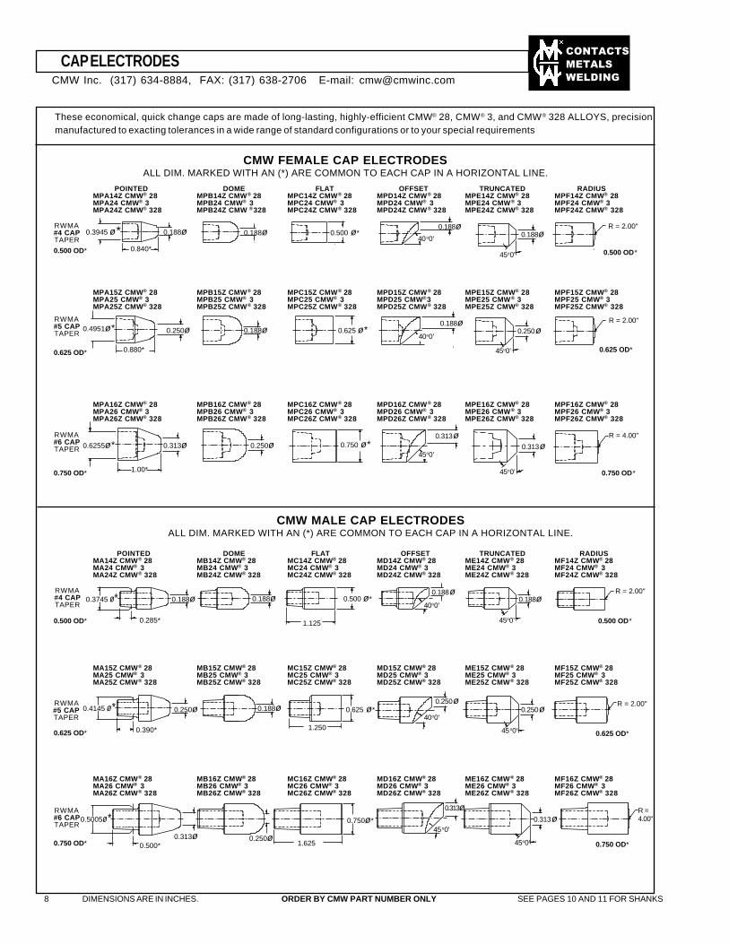
CMW FEMALE CAP ELECTRODESALL DIM. MARKED WITH AN (*) ARE COMMON TO EACH CAP IN A HORIZONTAL LINE.
POINTEDMPA14Z CMW® 28MPA24 CMW® 3MPA24Z CMW® 328
DOMEMPB14Z CMW® 28MPB24 CMW® 3MPB24Z CMW ®328
FLATMPC14Z CMW® 28MPC24 CMW® 3MPC24Z CMW® 328
OFFSETMPD14Z CMW® 28MPD24 CMW® 3MPD24Z CMW® 328
TRUNCATEDMPE14Z CMW® 28MPE24 CMW® 3MPE24Z CMW® 328
RADIUSMPF14Z CMW® 28MPF24 CMW® 3MPF24Z CMW® 328
RWMA#4 CAPTAPER
MPA15Z CMW® 28MPA25 CMW® 3MPA25Z CMW® 328
MPB15Z CMW® 28MPB25 CMW® 3MPB25Z CMW® 328
MPC15Z CMW® 28MPC25 CMW® 3MPC25Z CMW® 328
MPD15Z CMW® 28MPD25 CMW®3MPD25Z CMW® 328
MPE15Z CMW® 28MPE25 CMW® 3MPE25Z CMW® 328
MPF15Z CMW® 28MPF25 CMW® 3MPF25Z CMW® 328
CMW MALE CAP ELECTRODESALL DIM. MARKED WITH AN (*) ARE COMMON TO EACH CAP IN A HORIZONTAL LINE.
POINTEDMA14Z CMW® 28MA24 CMW® 3MA24Z CMW® 328
FLATMC14Z CMW® 28MC24 CMW® 3MC24Z CMW® 328
OFFSETMD14Z CMW® 28MD24 CMW® 3MD24Z CMW® 328
TRUNCATEDME14Z CMW® 28ME24 CMW® 3ME24Z CMW® 328
RADIUSMF14Z CMW® 28MF24 CMW® 3MF24Z CMW® 328
DOMEMB14Z CMW® 28MB24 CMW® 3MB24Z CMW® 328
RWMA#4 CAPTAPER
MB15Z CMW® 28MB25 CMW® 3MB25Z CMW® 328
MC15Z CMW® 28MC25 CMW® 3MC25Z CMW® 328
MD15Z CMW® 28MD25 CMW® 3MD25Z CMW® 328
ME15Z CMW® 28ME25 CMW® 3ME25Z CMW® 328
MF15Z CMW® 28MF25 CMW® 3MF25Z CMW® 328
MA15Z CMW® 28MA25 CMW® 3MA25Z CMW® 328
RWMA#5 CAPTAPER
MB16Z CMW® 28MB26 CMW® 3MB26Z CMW® 328
MC16Z CMW® 28MC26 CMW® 3MC26Z CMW® 328
MD16Z CMW® 28MD26 CMW® 3MD26Z CMW® 328
ME16Z CMW® 28ME26 CMW® 3ME26Z CMW® 328
MF16Z CMW® 28MF26 CMW® 3MF26Z CMW® 328
MA16Z CMW® 28MA26 CMW® 3MA26Z CMW® 328
RWMA#6 CAPTAPER
RWMA#5 CAPTAPER
MPA16Z CMW® 28MPA26 CMW® 3MPA26Z CMW® 328
MPB16Z CMW® 28MPB26 CMW® 3MPB26Z CMW® 328
MPC16Z CMW® 28MPC26 CMW® 3MPC26Z CMW® 328
MPD16Z CMW® 28MPD26 CMW® 3MPD26Z CMW® 328
MPE16Z CMW® 28MPE26 CMW® 3MPE26Z CMW® 328
MPF16Z CMW® 28MPF26 CMW® 3MPF26Z CMW® 328
CAP ELECTRODES
8 DIMENSIONS ARE IN INCHES. ORDER BY CMW PART NUMBER ONLY SEE PAGES 10 AND 11 FOR SHANKS
These economical, quick change caps are made of long-lasting, highly-efficient CMW® 28, CMW® 3, and CMW® 328 ALLOYS, precisionmanufactured to exacting tolerances in a wide range of standard configurations or to your special requirements
CMW Inc. (317) 634-8884, FAX: (317) 638-2706 E-mail: [email protected]
0.500 OD*
0.188øR = 2.00"
0.500 OD*
0.4951ø*
0.625 OD*
0.250ø
0.880*
0.188ø40o0'
0.250ø
45o0'
R = 2.00"
0.625 OD*
RWMA#6 CAPTAPER
0.750 OD* 0.750 OD*
0.500 OD*
R = 2.00"
0.500 OD*
0.625 OD* 0.625 OD*
R = 2.00"
0.750 OD* 0.750 OD*
0.3945 ø* 0.188ø 0.500 ø*0.188ø
40o0'0.188ø
45o0'
0.188ø 0.625 ø*
0.6255ø* 0.313ø
1.00*
0.250ø 0.750 ø*0.313ø
45o0'0.313ø
45o0'
R = 4.00"
0.188ø 0.500 ø*
1.125
0.188ø40o0'
0.188ø
45o0'
0.188ø 0.625 ø*
1.250
0.250ø
40o0'0.250ø
45o0'
0.250ø
0.750ø*
1.625
45o0'
0.313ø0.313ø
45o0'
R =4.00"
0.250ø0.4145 ø*
0.390*
0.313ø
0.5005ø*
0.500*
0.188ø0.3745 ø*
0.285*
0.840*
��������
�����
����
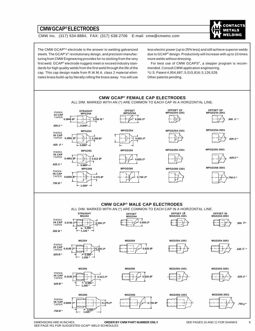
CMW GCAP® ELECTRODES
DIMENSIONS ARE IN INCHES. ORDER BY CMW PART NUMBER ONLY SEE PAGES 10 AND 11 FOR SHANKS 9SEE PAGE #51 FOR SUGGESTED GCAP® WELD SCHEDULES
The CMW GCAP®* electrode is the answer to welding galvanizedsteels. The GCAP’s® revolutionary design, and precision manufac-turing from CMW Engineering provides for no sticking from the veryfirst weld. GCAP® electrode nuggets meet or exceed industry stan-dards for high quality welds from the first weld through the life of thecap. This cap design made from R.W.M.A. class 2 material elimi-nates brass build-up by literally rolling the brass away. You will use
less electric power (up to 25% less) and still achieve superior weldsdue to GCAP® design. Productivity will increase with up to 10 timesmore welds without dressing.
For best use of CMW GCAPS®, a stepper program is recom-mended. Consult CMW application engineering.*U.S. Patent 4,954,687; 5,015,816; 5,126,528.Other patents pending.
CMW GCAP® FEMALE CAP ELECTRODESALL DIM. MARKED WITH AN (*) ARE COMMON TO EACH CAP IN A HORIZONTAL LINE.
RWMA#4 CAPTAPER
RWMA#5 CAPTAPER
RWMA#5 CAPTAPER
CMW GCAP® MALE CAP ELECTRODESALL DIM. MARKED WITH AN (*) ARE COMMON TO EACH CAP IN A HORIZONTAL LINE.
RWMA#6 CAPTAPER
OFFSETMGD244
OFFSET 15MGD244-1501
OFFSET 30MGD244-3001
MG254 MGD254 MGD254-1501 MGD254-3001
MG255 MGD255 MGD255-1501 MGD255-3001
MGD266-3001
OFFSET 15o
MPGD244-1501OFFSET 30o
MPGD244-3001OFFSET
MPGD244STRAIGHT
MPG244
.750 *
.500 *
.625 *
RWMA#4 CAPTAPER
.625 *
STRAIGHTMG244
MPG254
MPG255
MPG266
MPGD255
MPGD254 MPGD254-1501
MPGD255-1501
MPGD266-1501 MPGD266-3001
MPGD255-3001
MPGD254-3001
.625 Ø *
.750 Ø *
.625 Ø *
.500 Ø *
.500 Ø *
.625 Ø *
.625 Ø *
.750 Ø *
Ø
Ø
Ø
Ø
°
CMW Inc. (317) 634-8884, FAX: (317) 638-2706 E-mail: [email protected]
0.313 Ø*
MG266 MGD266 MGD266-1501
0.625 Ø*
0.625 Ø* 0.4951 Ø*
0.880*
RWMA#5 CAPTAPER
.500 Ø *
.625 Ø *
RWMA#5 CAPTAPER
.750 Ø *
RWMA#6 CAPTAPER
.625 Ø *
0.500 Ø*
0.4951 Ø* 0.250 Ø*
0.880*
0.375 Ø* 0.6255 Ø*
1.000*
0.750 Ø*
MPGD266
0.250 Ø * 0.3945 Ø*
0.840*
0.500 Ø*
0.625 Ø*
0.625 Ø*
0.750 Ø*
0.250 Ø* 0.3745 Ø*
0.285 *1.125 *
0.4145 Ø* 0.250 Ø*
0.390 *1.250 *
0.313 Ø* 0.4145 Ø*
0.390 * 1.250 *
0.375 Ø* 0.5005 Ø*
0.500 * 1.625 *
��������
�����
����
��������
�����
����
10 DIMENSIONS ARE IN INCHES. ORDER BY CMW PART NUMBER ONLY SEE PAGES 8 AND 9 FOR CMW STANDARD AND GCAP ELECTRODE CAPS
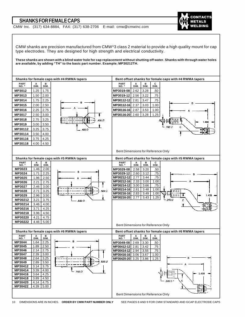
CMW shanks are precision manufactured from CMW®3 class 2 material to provide a high quality mount for captype electrodes. They are designed for high strength and electrical conductivity.
These shanks are shown with a blind water hole for cap replacement without shutting off water. Shanks with through water holesare available, by adding “TH” to the basic part number. Example; MP30212TH.
Shanks for female caps with #4 RWMA tapers Bent offset shanks for female caps with #4 RWMA tapers
Shanks for female caps with #5 RWMA tapers Bent offset shanks for female caps with #5 RWMA tapers
Shanks for female caps with #6 RWMA tapers Bent offset shanks for female caps with #6 RWMA tapers
Bent Dimensions for Reference Only
PART A BNO. * DIM. DIM.
MP3012 1.25 1.75
MP3013 1.50 2.00
MP3014 1.75 2.25
MP3015 2.00 2.50
MP3016 2.25 2.75
MP3017 2.50 3.00
MP3018 2.75 3.25
MP3019 3.00 3.50
MP30112 3.25 3.75
MP30114 3.50 4.00
MP30116 3.75 4.25
MP30118 4.00 4.50
PART A B CNO. * DIM. DIM. DIM.
MP3019-08 2.62 3.28 .50
MP3019-12 2.56 3.22 .75
MP30112-12 2.81 3.47 .75
MP30112-16 2.37 3.03 1.00
MP30116-16 2.87 3.53 1.00
MP30116-20 2.60 3.28 1.25
Bent Dimensions for Reference Only
PART A BNO. * DIM. DIM.
MP3023 1.46 2.00MP3024 1.71 2.25MP3025 1.96 2.50MP3026 2.21 2.75MP3027 2.46 3.00MP3028 2.71 3.25MP3029 2.96 3.50MP30212 3.21 3.75MP30214 3.46 4.00MP30216 3.71 4.25MP30218 3.96 4.50MP30220 4.21 4.75MP30222 4.46 5.00
PART A B CNO. * DIM. DIM. DIM.
MP3029-08 2.58 3.20 .50MP3029-12 2.60 3.12 .75MP30212-12 2.77 3.44 .75MP30212-16 2.33 3.00 1.00MP30214-12 3.00 3.66 .75MP30214-16 2.81 3.48 1.00MP30216-16 2.83 3.49 1.00MP30216-20 2.77 3.43 1.25
Bent Dimensions for Reference Only
PART A BNO. * DIM. DIM.
MP3044 1.64 2.25MP3045 1.89 2.50MP3046 2.14 2.75MP3047 2.39 3.00MP3048 2.64 3.25MP3049 2.89 3.50MP30412 3.14 3.75MP30414 3.39 4.00MP30416 3.64 4.25MP30418 3.89 4.50MP30420 4.14 4.75MP30422 4.39 5.00
PART A B CNO. * DIM. DIM. DIM.
MP3049-08 2.69 3.30 .50MP30412-12 2.81 3.42 .75MP30414-12 2.94 3.55 .75MP30416-16 3.06 3.67 1.00MP30420-20 3.25 3.86 1.25 B
A
1.438
.245 Ð * C
CMW Inc. (317) 634-8884, FAX: (317) 638-2706 E-mail: [email protected]
SHANKS FOR FEMALE CAPS
��������
�����
����
PART A B CNO. * DIM. DIM. DIM.
3028-08 2.37 3.12 .50
3028-12 2.31 3.06 .75
30212-12 2.81 3.56 .75
30212-16 2.37 3.12 1.00
30214-12 3.06 3.81 .75
30214-16 2.62 3.37 1.00
30214-20 2.37 3.12 1.25
30216-16 2.87 3.62 1.00
30216-20 2.62 3.37 1.25
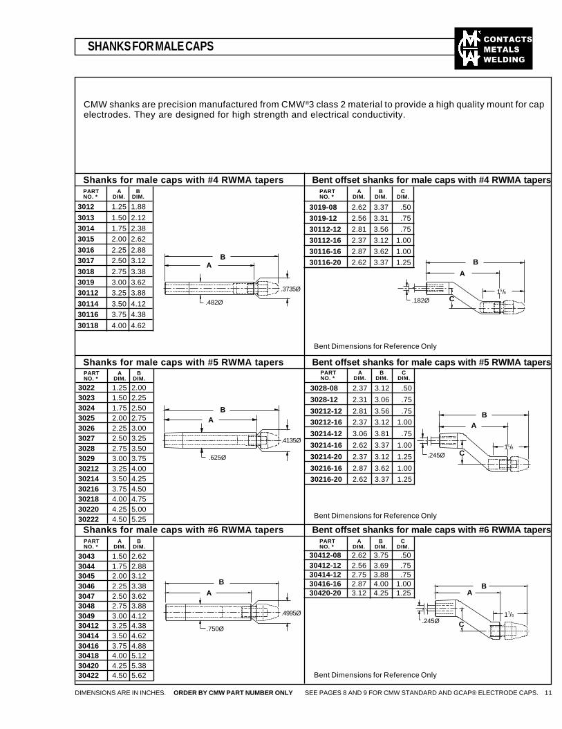
SHANKS FOR MALE CAPS
DIMENSIONS ARE IN INCHES. ORDER BY CMW PART NUMBER ONLY SEE PAGES 8 AND 9 FOR CMW STANDARD AND GCAP® ELECTRODE CAPS. 11
Shanks for male caps with #4 RWMA tapers Bent offset shanks for male caps with #4 RWMA tapers
Shanks for male caps with #5 RWMA tapers Bent offset shanks for male caps with #5 RWMA tapers
Shanks for male caps with #6 RWMA tapers Bent offset shanks for male caps with #6 RWMA tapers
Bent Dimensions for Reference Only
PART A BNO. * DIM. DIM.
3012 1.25 1.88
3013 1.50 2.123014 1.75 2.383015 2.00 2.62
3016 2.25 2.883017 2.50 3.12
3018 2.75 3.383019 3.00 3.6230112 3.25 3.88
30114 3.50 4.1230116 3.75 4.38
30118 4.00 4.62
PART A B CNO. * DIM. DIM. DIM.
3019-08 2.62 3.37 .50
3019-12 2.56 3.31 .75
30112-12 2.81 3.56 .75
30112-16 2.37 3.12 1.00
30116-16 2.87 3.62 1.00
30116-20 2.62 3.37 1.25
Bent Dimensions for Reference Only
Bent Dimensions for Reference Only
PART A B CNO. * DIM. DIM. DIM.
30412-08 2.62 3.75 .5030412-12 2.56 3.69 .7530414-12 2.75 3.88 .7530416-16 2.87 4.00 1.0030420-20 3.12 4.25 1.25
CMW shanks are precision manufactured from CMW®3 class 2 material to provide a high quality mount for capelectrodes. They are designed for high strength and electrical conductivity.
PART A BNO. * DIM. DIM.
3022 1.25 2.003023 1.50 2.253024 1.75 2.503025 2.00 2.753026 2.25 3.003027 2.50 3.253028 2.75 3.503029 3.00 3.7530212 3.25 4.0030214 3.50 4.2530216 3.75 4.5030218 4.00 4.7530220 4.25 5.0030222 4.50 5.25
PART A BNO. * DIM. DIM.
3043 1.50 2.623044 1.75 2.883045 2.00 3.123046 2.25 3.383047 2.50 3.623048 2.75 3.883049 3.00 4.1230412 3.25 4.3830414 3.50 4.6230416 3.75 4.8830418 4.00 5.1230420 4.25 5.3830422 4.50 5.62
B
A
C.182Ø15/8
BA
C.245Ø15/8
BA
C.245Ø17/8
BA
.482Ø
.3735Ø
BA
.4135Ø
.625Ø
B
A
.750Ø
.4995Ø
��������
�����
����
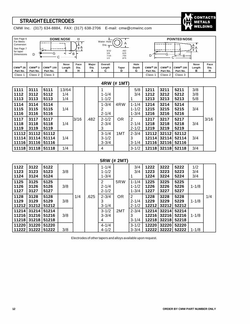
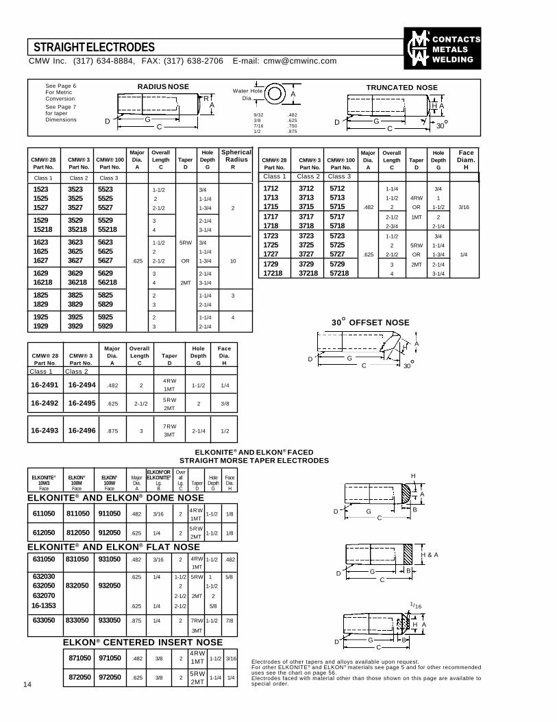
Nose Face Major Overall Hole Nose FaceCMW® 28 CMW® 3 CMW® 100 Length Dia. Dia. Length Taper Depth CMW® 28 CMW® 3 CMW® 100 Length Dia.Part No. Part No. Part No. B H A C D G Part No. Part No. Part No. B HClass 1 Class 2 Class 3 Class 1 Class 2 Class 3
See Page 6For MetricConversion
See Page 7for taperDimensions
5RW (# 2MT)
DOME NOSE POINTED NOSE
9/323/87/161/2
.482
.625
.750
.875
1111 3111 5111 13/64 1 5/8 1211 3211 5211 3/81112 3112 5112 1/4 1-1/4 3/4 1212 3212 5212 3/81113 3113 5113 1/4 1-1/2 1 1213 3213 5213 5/81114 3114 5114 1-3/4 4RW 1-1/4 1214 3214 52141115 3115 5115 1/4 2 1-1/2 1215 3215 5215 3/41116 3116 5116 2-1/4 1-3/4 1216 3216 52161117 3117 5117 3/16 .482 2-1/2 OR 2 1217 3217 5217 3/161118 3118 5118 1/4 2-3/4 2-1/4 1218 3218 5218 3/41119 3119 5119 3 2-1/2 1219 3219 521911112 31112 51112 3-1/4 1MT 2-3/4 12112 32112 5211211114 31114 51114 1/4 3-1/2 3 12114 32114 52114 3/411116 31116 51116 3-3/4 3-1/4 12116 32116 5211611118 31118 51118 1/4 4 3-1/2 12118 32118 52118 3/4
1122 3122 5122 1-1/4 3/4 1222 3222 5222 1/21123 3123 5123 3/8 1-1/2 3/4 1223 3223 5223 3/41124 3124 5124 1-3/4 1 1224 3224 5224 3/41125 3125 5125 2 5RW 1-1/4 1225 3225 52251126 3126 5126 3/8 2-1/4 1-1/2 1226 3226 5226 1-1/81127 3127 5127 2-1/2 1-3/4 1227 3227 52271128 3128 5128 1/4 .625 2-3/4 OR 2 1228 3228 5228 1/41129 3129 5129 3/8 3 2-1/4 1229 3229 5229 1-1/811212 31212 51212 3-1/4 2-1/2 12212 32212 5221211214 31214 51214 3-1/2 2MT 2-3/4 12214 32214 5221411216 31216 51216 3/8 3-3/4 3 12216 32216 52216 1-1/811218 31218 51218 4 3-1/4 12218 32218 5221811220 31220 51220 4-1/4 3-1/2 12220 32220 5222011222 31222 51222 3/8 4-1/2 3-3/4 12222 32222 52222 1-1/8
Electrodes of other tapers and alloys available upon request.
12 ORDER BY CMW PART NUMBER ONLY
H A
GC B
AWater HoleDia.
A
DD
H
BGC
❤
STRAIGHT ELECTRODESCMW Inc. (317) 634-8884, FAX: (317) 638-2706 E-mail: [email protected]
4RW (# 1MT)
��������
�����
����
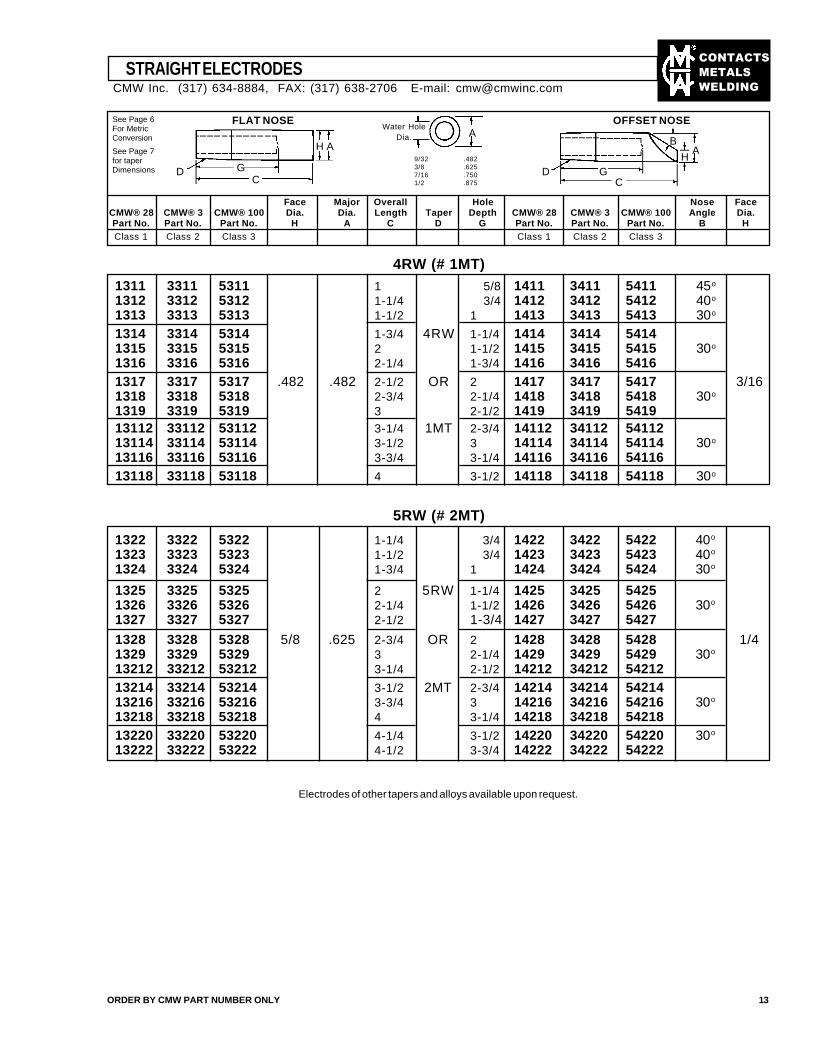
Face Major Overall Hole Nose FaceCMW® 28 CMW® 3 CMW® 100 Dia. Dia. Length Taper Depth CMW® 28 CMW® 3 CMW® 100 Angle Dia.Part No. Part No. Part No. H A C D G Part No. Part No. Part No. B HClass 1 Class 2 Class 3 Class 1 Class 2 Class 3
See Page 6For MetricConversion
See Page 7for taperDimensions
4RW (# 1MT)
5RW (# 2MT)
FLAT NOSE OFFSET NOSE
9/323/87/161/2
.482
.625
.750
.875
1311 3311 5311 1 5/8 1411 3411 5411 45o
1312 3312 5312 1-1/4 3/4 1412 3412 5412 40o
1313 3313 5313 1-1/2 1 1413 3413 5413 30o
1314 3314 5314 1-3/4 4RW 1-1/4 1414 3414 54141315 3315 5315 2 1-1/2 1415 3415 5415 30o
1316 3316 5316 2-1/4 1-3/4 1416 3416 54161317 3317 5317 .482 .482 2-1/2 OR 2 1417 3417 5417 3/161318 3318 5318 2-3/4 2-1/4 1418 3418 5418 30o
1319 3319 5319 3 2-1/2 1419 3419 541913112 33112 53112 3-1/4 1MT 2-3/4 14112 34112 5411213114 33114 53114 3-1/2 3 14114 34114 54114 30o
13116 33116 53116 3-3/4 3-1/4 14116 34116 5411613118 33118 53118 4 3-1/2 14118 34118 54118 30o
1322 3322 5322 1-1/4 3/4 1422 3422 5422 40o
1323 3323 5323 1-1/2 3/4 1423 3423 5423 40o
1324 3324 5324 1-3/4 1 1424 3424 5424 30o
1325 3325 5325 2 5RW 1-1/4 1425 3425 54251326 3326 5326 2-1/4 1-1/2 1426 3426 5426 30o
1327 3327 5327 2-1/2 1-3/4 1427 3427 5427
1328 3328 5328 5/8 .625 2-3/4 OR 2 1428 3428 5428 1/41329 3329 5329 3 2-1/4 1429 3429 5429 30o
13212 33212 53212 3-1/4 2-1/2 14212 34212 5421213214 33214 53214 3-1/2 2MT 2-3/4 14214 34214 5421413216 33216 53216 3-3/4 3 14216 34216 54216 30o
13218 33218 53218 4 3-1/4 14218 34218 5421813220 33220 53220 4-1/4 3-1/2 14220 34220 54220 30o
13222 33222 53222 4-1/2 3-3/4 14222 34222 54222
Electrodes of other tapers and alloys available upon request.
ORDER BY CMW PART NUMBER ONLY 13
GD
AAH
CD G
C
B
HA
STRAIGHT ELECTRODESCMW Inc. (317) 634-8884, FAX: (317) 638-2706 E-mail: [email protected]
Water HoleDia.
��������
�����
����
16-2491 16-2494 .482 2 1-1/2 1/4
16-2492 16-2495 .625 2-1/2 2 3/8
Major Overall HoleCMW® 28 CMW® 3 CMW® 100 Dia. Length Taper DepthPart No. Part No. Part No. A C D G
1712 3712 5712 1-1/4 3/4
1713 3713 5713 1-1/2 4RW 1
1715 3715 5715 .482 2 OR 1-1/2 3/16
1717 3717 5717 2-1/2 1MT 2
1718 3718 5718 2-3/4 2-1/4
1723 3723 5723 1-1/2 3/4
1725 3725 5725 2 5RW 1-1/4
1727 3727 5727 .625 2-1/2 OR 1-3/4 1/4
1729 3729 5729 3 2MT 2-1/4
17218 37218 57218 4 3-1/4
STRAIGHT ELECTRODES
See Page 6For MetricConversion
See Page 7for taperDimensions
SphericalRadius
FaceDiam.
H
CMW® 28Part No.
HoleDepth
G
FaceDia.
HCMW® 3Part No.
MajorDia.
A
OverallLength
CTaper
D
ELKONITE® AND ELKON® FACEDSTRAIGHT MORSE TAPER ELECTRODES
ELKON® OR OverELKONITE® ELKON® ELKON® Major ELKONITE® all Hole Face
10W3 100M 100W Dia. Lg. Lg. Taper Depth Dia.Face Face Face A B C D G H
ELKONITE® AND ELKON® DOME NOSE
611050 811050 911050 .482 3/16 2 1-1/2 1/8
612050 812050 912050 .625 1/4 2 1-1/2 1/8
4RW
1MT
5RW
2MT
ELKONITE® AND ELKON® FLAT NOSE631050 831050 931050 .482 3/16 2 1-1/2 .482
632030 .625 1/4 1-1/2 5RW 1 5/8
632050 832050 932050 2 1-1/2
632070 2-1/2 2MT 2
16-1353 .625 1/4 2-1/2 5/8
633050 833050 933050 .875 1/4 2 7RW 1-1/2 7/8
3MT
4RW
1MT
Electrodes of other tapers and alloys available upon request.For other ELKONITE® and ELKON® materials see page 5 and for other recommendeduses see the chart on page 56.Electrodes faced with material other than those shown on this page are available tospecial order.
9/323/87/161/2
.482
.625
.750
.875
Class 1 Class 2 Class 3
Major Overall HoleCMW® 28 CMW® 3 CMW® 100 Dia. Length Taper DepthPart No. Part No. Part No. A C D G R
Class 1 Class 2 Class 3
1523 3523 5523 1-1/2 3/4
1525 3525 5525 2 1-1/4
1527 3527 5527 2-1/2 1-3/4 2
1529 3529 5529 3 2-1/4
15218 35218 55218 4 3-1/4
1623 3623 5623 1-1/2 5RW 3/4
1625 3625 5625 2 1-1/4
1627 3627 5627 .625 2-1/2 OR 1-3/4 10
1629 3629 5629 3 2-1/4
16218 36218 56218 4 2MT 3-1/4
1825 3825 5825 2 1-1/4 3
1829 3829 5829 3 2-1/4
1925 3925 5925 2 1-1/4 4
1929 3929 5929 3 2-1/4
16-2493 16-2496 .875 3 2-1/4 1/27RW
3MT
Class 1 Class 2
5RW
2MT
4RW
1MT
4RW1MT
5RW2MT
ELKON® CENTERED INSERT NOSE
871050 971050 .482 3/8 2 1-1/2 3/16
872050 972050 .625 3/8 2 1-1/4 1/4
D 30°
A
D
30° OFFSET NOSE
D GC 30°
H A
H
A
BC
GD
H & A
CGD B
H A
BGC
D
1/16
TRUNCATED NOSERADIUS NOSE
GC
H A
GC
AR
CMW Inc. (317) 634-8884, FAX: (317) 638-2706 E-mail: [email protected]
14
Water HoleDia.
��������
�����
����
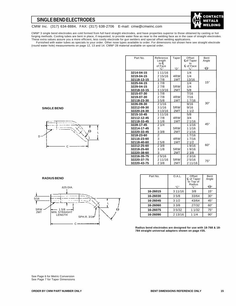
SINGLE BEND ELECTRODES
SINGLE BEND
CMW® 3 single bend electrodes are cold formed from full hard straight electrodes, and have properties superior to those obtained by casting or hotforging methods. Cooling tubes are bent in place, if requested, to provide water flow as near to the welding face as in the case of straight electrodes.These extra values assure you a more efficient, less costly electrode for gun welders and special offset welding applications.
Furnished with water tubes as specials to your order. Other nose types available to order. For dimensions not shown here see straight electrode(round water hole) measurements on page 12, 13 and 14. CMW® 28 material available on special order.
Part No. Reference Taper Offset BentLength CL of Taper Angle
to CL toof Face CL of Face
“C” “D” “L” “Θ”
3214-04-15 1 11/16 1/43219-04-15 2 15/16 4RW 1/432118-13-15 3 7/8 1MT 13/163225-04-15 1 7/8 1/43229-04-15 2 7/8 5RW 1/432218-10-15 3 13/16 2MT 5/83215-07-30 1 7/8 7/163219-07-30 2 7/8 4RW 7/1632118-23-30 3 5/8 1MT 1 7/163226-09-30 2 1/16 9/1632212-09-30 3 1/16 5RW 9/1632220-24-30 3 13/16 2MT 1 1/23215-10-45 1 11/16 5/832112-12-45 2 7/8 4RW 3/432118-33-45 3 1/8 1MT 2 1/163228-17-45 2 1/4 1 1/1632214-17-45 3 5RW 1 1/1632220-33-45 3 3/8 2MT 2 1/163218-23-60 2 1 7/1632116-23-60 3 4RW 1 7/1632118-40-60 2 5/8 1MT 2 1/232212-25-60 2 3/8 1 9/1632218-25-60 3 1/8 5RW 1 9/1632220-38-60 3 2MT 2 3/832216-35-75 2 5/16 2 3/1632220-37-75 2 11/16 5RW 2 5/1632220-43-75 2 3/8 2MT 2 11/16
ORDER BY CMW PART NUMBER ONLY BENT DIMENSIONS REFERENCE ONLY 15
RADIUS BEND
16-26015 3 11/16 3/8 15°
16-26030 3 5/8 33/64 30°
16-26045 3 1/2 43/64 45°
16-26060 3 3/8 27/32 60°
16-26075 3 5/32 1 1/32 75°
16-26090 2 13/16 1 1/4 90°
Part No. O.A.L. Offset BentCL of Taper Angleto Top ofRadius
“C” “L” “Θ”
Radius bend electrodes are designed for use with 18-768 & 18-784 straight universal adapters shown on page #35.
See Page 6 for Metric ConversionSee Page 7 for Taper Dimensions
.625 DIA.
5/16
5RW2MT
1 5/8MIN. STRAIGHT
LENGTH
C
SPH.R. 3/16
Θ
L
LΘ
C
D
15°
30°
45°
60°
75°
CMW Inc. (317) 634-8884, FAX: (317) 638-2706 E-mail: [email protected]
��������
�����
����
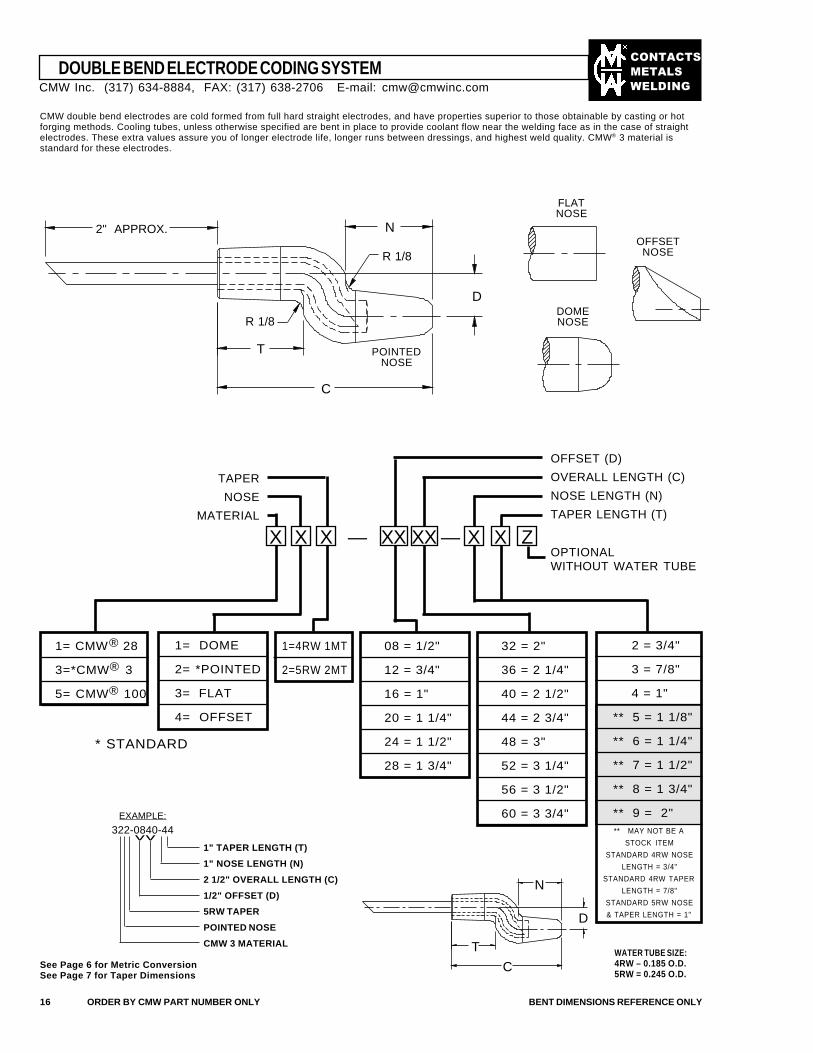
DOUBLE BEND ELECTRODE CODING SYSTEM
CMW double bend electrodes are cold formed from full hard straight electrodes, and have properties superior to those obtainable by casting or hotforging methods. Cooling tubes, unless otherwise specified are bent in place to provide coolant flow near the welding face as in the case of straightelectrodes. These extra values assure you of longer electrode life, longer runs between dressings, and highest weld quality. CMW® 3 material isstandard for these electrodes.
16 ORDER BY CMW PART NUMBER ONLY BENT DIMENSIONS REFERENCE ONLY
1= CMW® 28
3=*CMW® 3
5= CMW® 100
1= DOME
2= *POINTED
3= FLAT
4= OFFSET
1=4RW 1MT
2=5RW 2MT
08 = 1/2"
12 = 3/4"
16 = 1"
20 = 1 1/4"
24 = 1 1/2"
28 = 1 3/4"
32 = 2"
36 = 2 1/4"
40 = 2 1/2"
44 = 2 3/4"
48 = 3"
52 = 3 1/4"
56 = 3 1/2"
60 = 3 3/4"
OFFSET (D)
OVERALL LENGTH (C)
NOSE LENGTH (N)
TAPER LENGTH (T)
TAPER
NOSE
MATERIAL
XX X X XXX XX ——
WATER TUBE SIZE:4RW – 0.185 O.D.5RW = 0.245 O.D.
* STANDARD
EXAMPLE:
322-0840-44vv
See Page 6 for Metric ConversionSee Page 7 for Taper Dimensions
2 = 3/4"
3 = 7/8"
4 = 1"
** 5 = 1 1/8"
** 6 = 1 1/4"
** 7 = 1 1/2"
** 8 = 1 3/4"
** 9 = 2"** MAY NOT BE A
STOCK ITEM
STANDARD 4RW NOSE
LENGTH = 3/4"
STANDARD 4RW TAPER
LENGTH = 7/8"
STANDARD 5RW NOSE
& TAPER LENGTH = 1"
FLATNOSE
DOMENOSE
OFFSETNOSE
1" TAPER LENGTH (T)
1" NOSE LENGTH (N)
2 1/2" OVERALL LENGTH (C)
1/2" OFFSET (D)
5RW TAPER
POINTED NOSE
CMW 3 MATERIAL
ZOPTIONALWITHOUT WATER TUBE
CMW Inc. (317) 634-8884, FAX: (317) 638-2706 E-mail: [email protected]
2" APPROX.
R 1/8
T
C
N
R 1/8
D
N
D
C
T
POINTEDNOSE
��������
�����
����
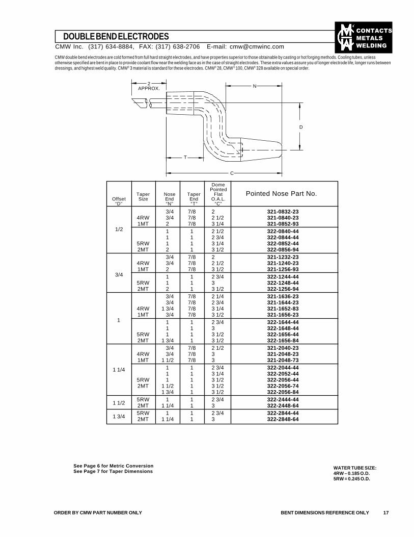
DOUBLE BEND ELECTRODES
CMW double bend electrodes are cold formed from full hard straight electrodes, and have properties superior to those obtainable by casting or hot forging methods. Cooling tubes, unlessotherwise specified are bent in place to provide coolant flow near the welding face as in the case of straight electrodes. These extra values assure you of longer electrode life, longer runs betweendressings, and highest weld quality. CMW® 3 material is standard for these electrodes. CMW® 28, CMW® 100, CMW® 328 available on special order.
ORDER BY CMW PART NUMBER ONLY BENT DIMENSIONS REFERENCE ONLY 17
DomePointed
Taper Nose Taper Flat Pointed Nose Part No.Offset Size End End O.A.L.
“D” “N” “T” “C”
3/4 7/8 2 321-0832-234RW 3/4 7/8 2 1/2 321-0840-231MT 2 7/8 3 1/4 321-0852-93
1 1 2 1/2 322-0840-441 1 2 3/4 322-0844-44
5RW 1 1 3 1/4 322-0852-442MT 2 1 3 1/2 322-0856-94
3/4 7/8 2 321-1232-234RW 3/4 7/8 2 1/2 321-1240-231MT 2 7/8 3 1/2 321-1256-93
1 1 2 3/4 322-1244-445RW 1 1 3 322-1248-442MT 2 1 3 1/2 322-1256-94
3/4 7/8 2 1/4 321-1636-23 3/4 7/8 2 3/4 321-1644-23
4RW 1 3/4 7/8 3 1/4 321-1652-831MT 3/4 7/8 3 1/2 321-1656-23
1 1 2 3/4 322-1644-441 1 3 322-1648-44
5RW 1 1 3 1/2 322-1656-442MT 1 3/4 1 3 1/2 322-1656-84
3/4 7/8 2 1/2 321-2040-234RW 3/4 7/8 3 321-2048-231MT 1 1/2 7/8 3 321-2048-73
1 1 2 3/4 322-2044-441 1 3 1/4 322-2052-44
5RW 1 1 3 1/2 322-2056-442MT 1 1/2 1 3 1/2 322-2056-74
1 3/4 1 3 1/2 322-2056-845RW 1 1 2 3/4 322-2444-442MT 1 1/4 1 3 322-2448-645RW 1 1 2 3/4 322-2844-442MT 1 1/4 1 3 322-2848-64
1/2
3/4
1
1 1/4
1 1/2
1 3/4
C
T
N
D
2APPROX.
See Page 6 for Metric ConversionSee Page 7 for Taper Dimensions
WATER TUBE SIZE:4RW – 0.185 O.D.5RW = 0.245 O.D.
CMW Inc. (317) 634-8884, FAX: (317) 638-2706 E-mail: [email protected]
��������
�����
����
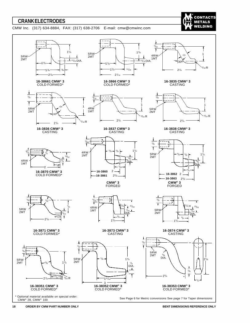
CRANK ELECTRODES
18 ORDER BY CMW PART NUMBER ONLY BENT DIMENSIONS REFERENCE ONLY
16-38661 CMW® 3COLD FORMED*
16-3866 CMW® 3COLD FORMED*
16-3835 CMW® 3CASTING
* Optional material available on special order: CMW® 28, CMW® 100 See Page 6 for Metric conversions See page 7 for Taper dimensions
16-3836 CMW® 3CASTING
16-3837 CMW® 3CASTING
16-3838 CMW® 3CASTING
16-3873 CMW® 3CASTING
16-3874 CMW® 3CASTING
16-38353 CMW® 3COLD FORMED*
9/32
23/4
3/8
11/8
3/8
11/4
13/32 DIA.
21/8
13/4
5RW2MT
11/8
11/16
11/32 DIA.
27/16
13/4
11/45RW2MT
9/32
1 /2
21/4
5/32 R
1
3/8
5RW2MT
30o
5 /8 1
21/4
4RW1MT
16-38352 CMW® 3COLD FORMED*
16-38351 CMW® 3COLD FORMED*
16-3871 CMW® 3COLD FORMED*
16-3870 CMW® 3COLD FORMED*
CMW® 3FORGED
CMW® 3FORGED
4RW1MT
2
19/32
5/83/8
3/4
216-386023/816-3861
3/8
4RW1MT
5/8 3/8
216-3862
23/816-3863
4RW1MT
3/4
3/8
5RW2MT
13/4
7/16
DIA.
1/4
3/16 R
5RW2MT 11/2
5RW2MT
5/8
5RW2MT
3/8
23/4
11
9/32 1/2
1/4
3/8
3/8
DIA.
9/32
11/4
3/8
DIA.
11/4
3/4
25/32
3/4
25/32
7/16
DIA.
1/4
13/4
9/323/8 5/8
7/8
5/161/2
21/8
5RW2MT
3/8
5/8
3/421/2
3/8
13/4
1/4
DIA.
115/16
3
3/8
5/8
DIA. 21/8
1/2
4RW1MT
5RW2MT
5/32 R
3/16 R 3/16 R
CMW Inc. (317) 634-8884, FAX: (317) 638-2706 E-mail: [email protected]
30o
23/4
5RW2MT
��������
�����
����
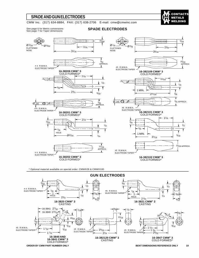
SPADE AND GUN ELECTRODES
ORDER BY CMW PART NUMBER ONLY BENT DIMENSIONS REFERENCE ONLY 19
SPADE ELECTRODES
GUN ELECTRODES
* Optional material available on special order: CMW®28 & CMW®100
See page 6 for Metric conversionsSee page 7 for Taper dimensions
16-382102 CMW® 3COLD FORMED*
16-38202 CMW® 3COLD FORMED*
16-382101 CMW® 3COLD FORMED*
16-38201 CMW® 3COLD FORMED*
16-382109 CMW® 3COLD FORMED*
16-38209 CMW® 3COLD FORMED*
16-3821 CMW® 3CASTING
16-3820 CMW® 3CASTING
16-3840 AND16-3841 CMW® 3COLD FORMED*
16-382120 CMW® 3CASTING
16-3847 CMW® 3COLD FORMED*
CMW Inc. (317) 634-8884, FAX: (317) 638-2706 E-mail: [email protected]
Ø 3/16 Ø 9/32
15/64
3/4APPROX.
11/4
31/16
Ø 1/4 Ø 3/8
5/16
15/8
35/16
15/16
FLATTENEDNOSE
FLATTENEDNOSE
# 4 R.W.M.A.ELECTRODE TAPER
#5 R.W.M.A.ELECTRODE TAPER
11/4
1/2
9/3223/4
5/8
5/8Ø .182Ø .245
15/16
1/2
3/8215/16
1 MIN.
3/4 APPROX.
# 4 R.W.M.A.ELECTRODE TAPER
#5 R.W.M.A.ELECTRODE TAPER
9/3211/4
1/2
1/4213/16
7/8HOLE
11/16
# 4 R.W.M.A.ELECTRODE TAPER
#5 R.W.M.A.ELECTRODE TAPER
3/8
11/4
1/2
5/16
15/16 APPROX.
31/16
1 MIN.
3/4
APPROX.
9/32
23/4
7/81
HOLE 1/4
1/2
3/8
9/16
3/8
# 4 R.W.M.A.ELECTRODE TAPER #5 R.W.M.A.
ELECTRODE TAPER
#5 R.W.M.A.ELECTRODE TAPER #5 R.W.M.A.
ELECTRODE TAPER#5 R.W.M.A.ELECTRODE TAPER
7/81
HOLE2 3/4
1/4
1/2
3/8
9/16
3/8
9/32
5 /1630o
1 1/41 3/4
29/32
1/2
13/16
5/16
21/419/16
3/8 3/8
7/16
19/32
5/325/16
1 7/8
1 1/4
3/8
5 /16
30o
16-3841 27/32
16-3840 131/32
APPROX.
APPROX.
��������
�����
����
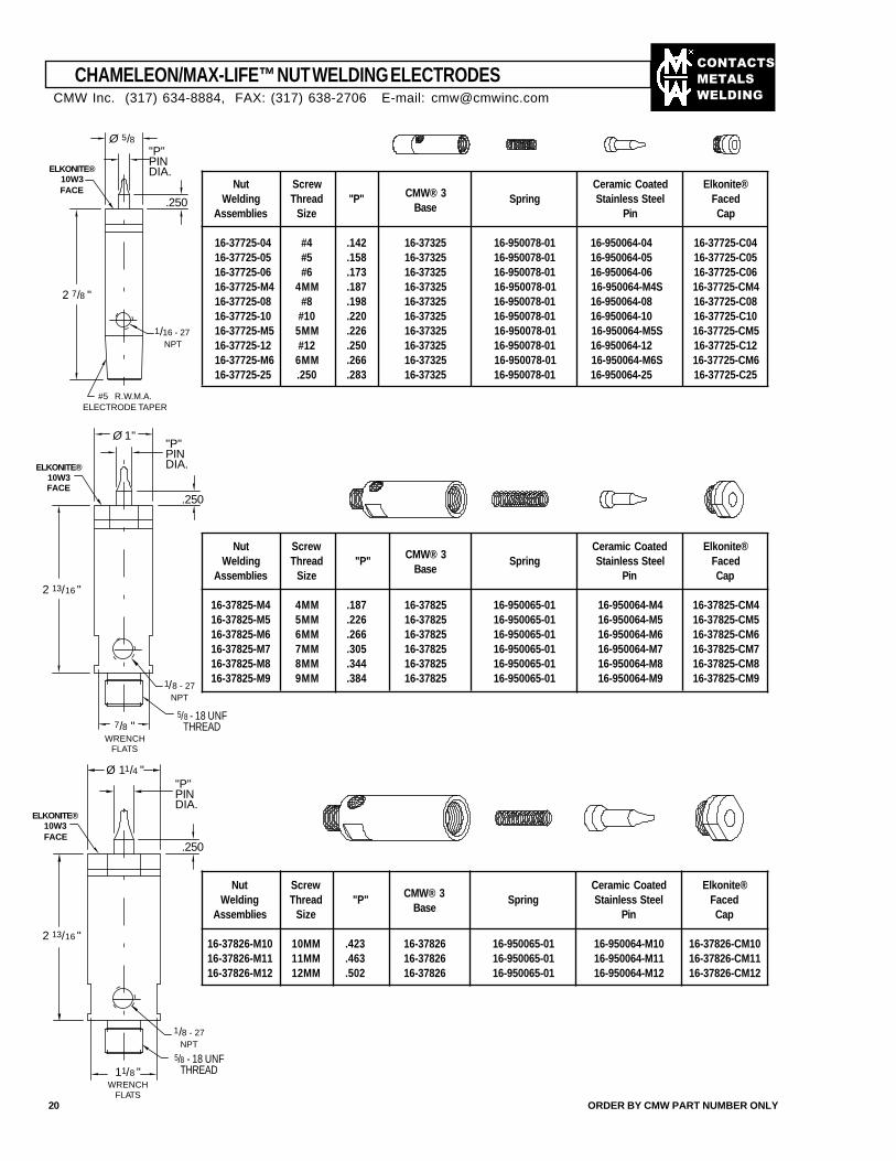
CHAMELEON/MAX-LIFE™ NUT WELDING ELECTRODES
Nut ScrewCMW® 3
Ceramic Coated Elkonite®Welding Thread "P"
BaseSpring Stainless Steel Faced
Assemblies Size Pin Cap
16-37725-04 #4 .142 16-37325 16-950078-01 16-950064-04 16-37725-C0416-37725-05 #5 .158 16-37325 16-950078-01 16-950064-05 16-37725-C0516-37725-06 #6 .173 16-37325 16-950078-01 16-950064-06 16-37725-C0616-37725-M4 4MM .187 16-37325 16-950078-01 16-950064-M4S 16-37725-CM416-37725-08 #8 .198 16-37325 16-950078-01 16-950064-08 16-37725-C0816-37725-10 #10 .220 16-37325 16-950078-01 16-950064-10 16-37725-C1016-37725-M5 5MM .226 16-37325 16-950078-01 16-950064-M5S 16-37725-CM516-37725-12 #12 .250 16-37325 16-950078-01 16-950064-12 16-37725-C1216-37725-M6 6MM .266 16-37325 16-950078-01 16-950064-M6S 16-37725-CM616-37725-25 .250 .283 16-37325 16-950078-01 16-950064-25 16-37725-C25
Nut ScrewCMW® 3
Ceramic Coated Elkonite®Welding Thread "P"
BaseSpring Stainless Steel Faced
Assemblies Size Pin Cap
16-37825-M4 4MM .187 16-37825 16-950065-01 16-950064-M4 16-37825-CM416-37825-M5 5MM .226 16-37825 16-950065-01 16-950064-M5 16-37825-CM516-37825-M6 6MM .266 16-37825 16-950065-01 16-950064-M6 16-37825-CM616-37825-M7 7MM .305 16-37825 16-950065-01 16-950064-M7 16-37825-CM716-37825-M8 8MM .344 16-37825 16-950065-01 16-950064-M8 16-37825-CM816-37825-M9 9MM .384 16-37825 16-950065-01 16-950064-M9 16-37825-CM9
Nut ScrewCMW® 3
Ceramic Coated Elkonite®Welding Thread "P"
BaseSpring Stainless Steel Faced
Assemblies Size Pin Cap
16-37826-M10 10MM .423 16-37826 16-950065-01 16-950064-M10 16-37826-CM1016-37826-M11 11MM .463 16-37826 16-950065-01 16-950064-M11 16-37826-CM1116-37826-M12 12MM .502 16-37826 16-950065-01 16-950064-M12 16-37826-CM12
20 ORDER BY CMW PART NUMBER ONLY
CMW Inc. (317) 634-8884, FAX: (317) 638-2706 E-mail: [email protected]
Ø 5/8"P"PINDIA.
.250
ELKONITE®10W3FACE
2 7/8 "
1/16 - 27NPT
#5 R.W.M.A.ELECTRODE TAPER
Ø 1""P"PINDIA.
.250
ELKONITE®10W3FACE
2 13/16 "
1/8 - 27NPT
5/8 - 18 UNFTHREAD7/8 "
WRENCHFLATS
5/8 - 18 UNFTHREAD
1/8 - 27NPT
11/8 "WRENCH
FLATS
2 13/16 "
ELKONITE®10W3FACE
Ø 11/4 ""P"PINDIA.
.250
��������
�����
����
7/8 "WRENCH
FLATS
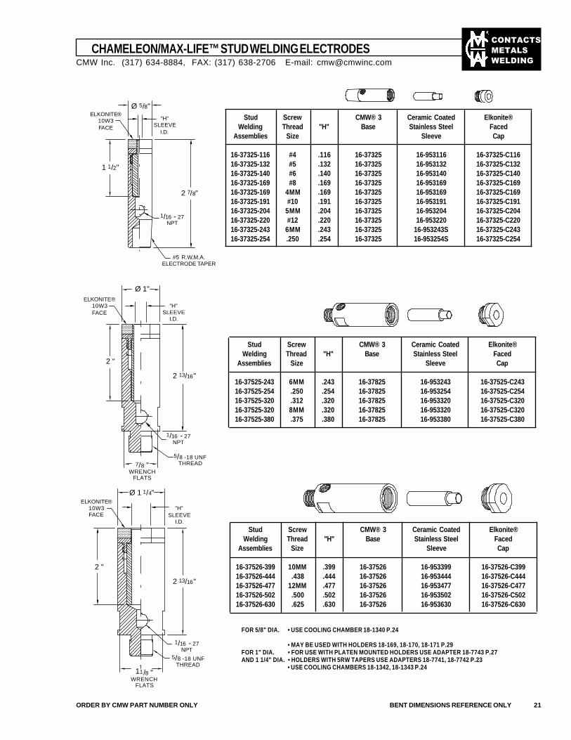
CHAMELEON/MAX-LIFE™ STUD WELDING ELECTRODES
Stud Screw CMW® 3 Ceramic Coated Elkonite®Welding Thread "H" Base Stainless Steel Faced
Assemblies Size Sleeve Cap
16-37325-116 #4 .116 16-37325 16-953116 16-37325-C11616-37325-132 #5 .132 16-37325 16-953132 16-37325-C13216-37325-140 #6 .140 16-37325 16-953140 16-37325-C14016-37325-169 #8 .169 16-37325 16-953169 16-37325-C16916-37325-169 4MM .169 16-37325 16-953169 16-37325-C16916-37325-191 #10 .191 16-37325 16-953191 16-37325-C19116-37325-204 5MM .204 16-37325 16-953204 16-37325-C20416-37325-220 #12 .220 16-37325 16-953220 16-37325-C22016-37325-243 6MM .243 16-37325 16-953243S 16-37325-C24316-37325-254 .250 .254 16-37325 16-953254S 16-37325-C254
Stud Screw CMW® 3 Ceramic Coated Elkonite®Welding Thread "H" Base Stainless Steel Faced
Assemblies Size Sleeve Cap
16-37525-243 6MM .243 16-37825 16-953243 16-37525-C24316-37525-254 .250 .254 16-37825 16-953254 16-37525-C25416-37525-320 .312 .320 16-37825 16-953320 16-37525-C32016-37525-320 8MM .320 16-37825 16-953320 16-37525-C32016-37525-380 .375 .380 16-37825 16-953380 16-37525-C380
Stud Screw CMW® 3 Ceramic Coated Elkonite®Welding Thread "H" Base Stainless Steel Faced
Assemblies Size Sleeve Cap
16-37526-399 10MM .399 16-37526 16-953399 16-37526-C39916-37526-444 .438 .444 16-37526 16-953444 16-37526-C44416-37526-477 12MM .477 16-37526 16-953477 16-37526-C47716-37526-502 .500 .502 16-37526 16-953502 16-37526-C50216-37526-630 .625 .630 16-37526 16-953630 16-37526-C630
FOR 5/8" DIA. • USE COOLING CHAMBER 18-1340 P.24
• MAY BE USED WITH HOLDERS 18-169, 18-170, 18-171 P.29FOR 1" DIA. • FOR USE WITH PLATEN MOUNTED HOLDERS USE ADAPTER 18-7743 P.27AND 1 1/4" DIA. • HOLDERS WITH 5RW TAPERS USE ADAPTERS 18-7741, 18-7742 P.23
• USE COOLING CHAMBERS 18-1342, 18-1343 P.24
ORDER BY CMW PART NUMBER ONLY BENT DIMENSIONS REFERENCE ONLY 21
CMW Inc. (317) 634-8884, FAX: (317) 638-2706 E-mail: [email protected]
Ø 5/8"ELKONITE®
10W3FACE
"H"SLEEVE
I.D.
1 1/2"
2 7/8"
1/16 - 27NPT
#5 R.W.M.A.ELECTRODE TAPER
Ø 1"
"H"SLEEVE
I.D.
ELKONITE®10W3FACE
2 13/16"
1/16 - 27NPT
2 "
11/8 "WRENCH
FLATS
1/16 - 27NPT
5/8 -18 UNFTHREAD
5/8 -18 UNFTHREAD
Ø 1 1/4"
"H"SLEEVE
I.D.
2 13/16"
2 "
ELKONITE®10W3FACE
��������
�����
����
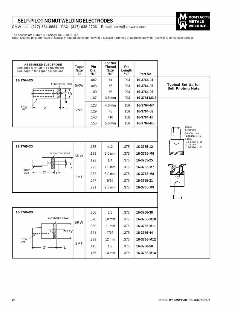
SELF-PILOTING NUT WELDING ELECTRODES
22 ORDER BY CMW PART NUMBER ONLY
The shanks are CMW® 3. Facings are ELKONITE®
Note: locating pins are made of specially treated aluminum, having a surface hardness of approximately 55 Rockwell C on outside surface.
16-3764-XX
5RW2MT
ASSEMBLED ELECTRODESee page 6 for Metric conversionsSee page 7 for Taper dimensions
16-3765-XX .166 #12 .375 16-3765-12
.189 6.0 mm .375 16-3765-M6
.192 1/4 .375 16-3765-25
.223 7.0 mm .375 16-3765-M7
.252 8.0 mm .375 16-3765-M8
.257 5/16 .375 16-3765-31
.291 9.0 mm .375 16-3765-M9
5RW
2MT
16-3766-XX .306 3/8 .375 16-3766-38
.320 10 mm .375 16-3766-M10
.359 11 mm .375 16-3766-M11
.361 7/16 .375 16-3766-44
.388 12 mm .375 16-3766-M12
.415 1/2 .375 16-3766-50
.455 14 mm .375 16-3766-M14
5RW
2MT5RW2MT
Typical Set-Up forSelf Piloting Nuts
UpperElectrode
5/8 Dia. use632050 p. 14
1 Dia.16-1392 p. 25
1-1/4 use16-1394 p. 25
5RW
2MT
CMW Inc. (317) 634-8884, FAX: (317) 638-2706 E-mail: [email protected]
For NutTaper Pin Thread PinSize Dia. Size Length
D “N” “N” “L” Part No.
.082 #4 .093 16-3764-04
.093 #5 .093 16-3764-05
.100 #6 .093 16-3764-06
.107 3.5 mm .093 16-3764-M3-5
.123 4.0 mm .156 16-3764-M4
.129 #8 .156 16-3764-08
.143 #10 .156 16-3764-10
.156 5.0 mm .156 16-3764-M5
ELKONITE® 10W3
5/8
N
L2"
5RW2MT
ELKONITE® 10W3
1"N
L2"
ELKONITE® 10W3
N 13/4"
2" L
��������
�����
����
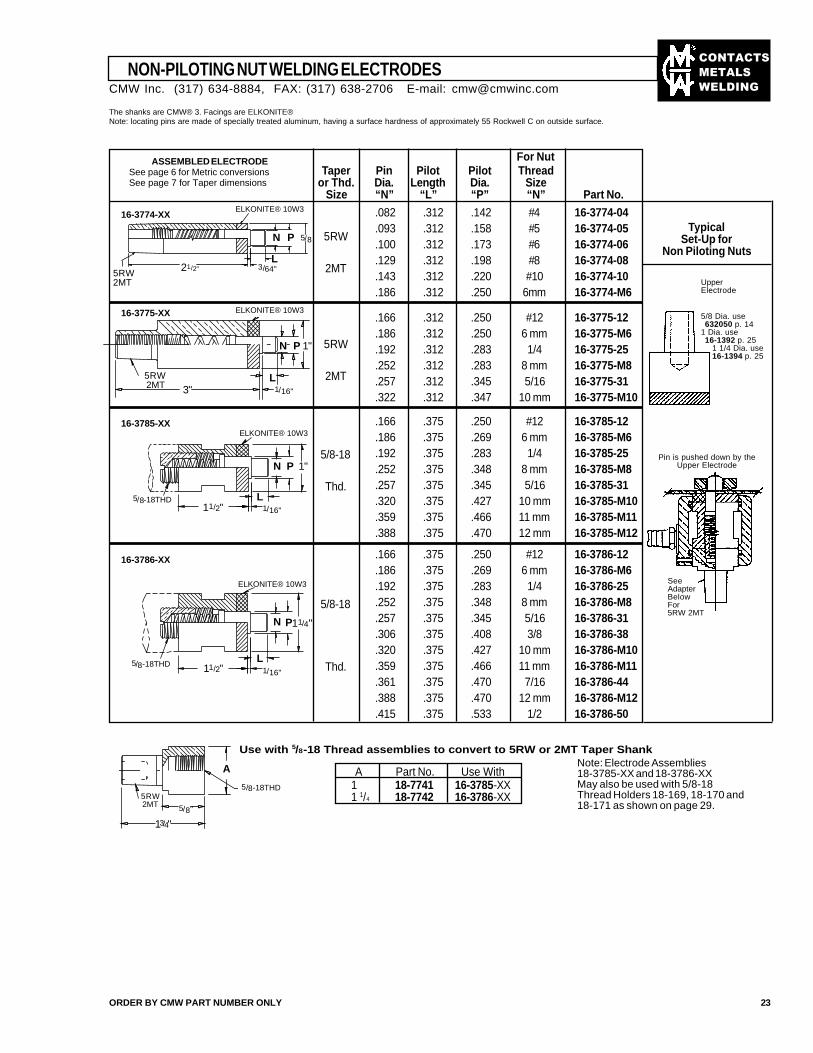
The shanks are CMW® 3. Facings are ELKONITE®Note: locating pins are made of specially treated aluminum, having a surface hardness of approximately 55 Rockwell C on outside surface.
ASSEMBLED ELECTRODESee page 6 for Metric conversionsSee page 7 for Taper dimensions
For NutTaper Pin Pilot Pilot Thread
or Thd. Dia. Length Dia. SizeSize “N” “L” “P” “N” Part No.
.082 .312 .142 #4 16-3774-04
.093 .312 .158 #5 16-3774-05
.100 .312 .173 #6 16-3774-06
.129 .312 .198 #8 16-3774-08
.143 .312 .220 #10 16-3774-10
.186 .312 .250 6mm 16-3774-M6
.166 .312 .250 #12 16-3775-12
.186 .312 .250 6 mm 16-3775-M6
.192 .312 .283 1/4 16-3775-25
.252 .312 .283 8 mm 16-3775-M8
.257 .312 .345 5/16 16-3775-31
.322 .312 .347 10 mm 16-3775-M10
.166 .375 .250 #12 16-3786-12
.186 .375 .269 6 mm 16-3786-M6
.192 .375 .283 1/4 16-3786-25
.252 .375 .348 8 mm 16-3786-M8
.257 .375 .345 5/16 16-3786-31
.306 .375 .408 3/8 16-3786-38
.320 .375 .427 10 mm 16-3786-M10
.359 .375 .466 11 mm 16-3786-M11
.361 .375 .470 7/16 16-3786-44
.388 .375 .470 12 mm 16-3786-M12
.415 .375 .533 1/2 16-3786-50
.166 .375 .250 #12 16-3785-12
.186 .375 .269 6 mm 16-3785-M6
.192 .375 .283 1/4 16-3785-25
.252 .375 .348 8 mm 16-3785-M8
.257 .375 .345 5/16 16-3785-31
.320 .375 .427 10 mm 16-3785-M10
.359 .375 .466 11 mm 16-3785-M11
.388 .375 .470 12 mm 16-3785-M12
5RW
2MT
5RW
2MT
5/8-18
Thd.
5/8-18
Thd.
TypicalSet-Up for
Non Piloting Nuts
Use with 5/8-18 Thread assemblies to convert to 5RW or 2MT Taper ShankNote: Electrode Assemblies18-3785-XX and 18-3786-XXMay also be used with 5/8-18Thread Holders 18-169, 18-170 and18-171 as shown on page 29.
A Part No. Use With1 18-7741 16-3785-XX1 1/4 18-7742 16-3786-XX
16-3785-XX
16-3786-XX
UpperElectrode
NON-PILOTING NUT WELDING ELECTRODES
ORDER BY CMW PART NUMBER ONLY 23
16-3775-XX
Pin is pushed down by theUpper Electrode
SeeAdapterBelowFor5RW 2MT
5/8 Dia. use632050 p. 14
1 Dia. use16-1392 p. 25
1 1/4 Dia. use16-1394 p. 25
CMW Inc. (317) 634-8884, FAX: (317) 638-2706 E-mail: [email protected]
16-3774-XXELKONITE® 10W3
N P 5/8
L3/64"21/2"
1/16"
1/16"
5RW2MT
5/8-18THD
A
5/8"
13/4"
5/8-18THD
N P 1"
L11/2"
5/8-18THD 11/2"L
N P11/4"
ELKONITE® 10W3
P 1"
3"5RW2MT
L1/16"
N
5RW2MT
ELKONITE® 10W3
ELKONITE® 10W3
��������
�����
����
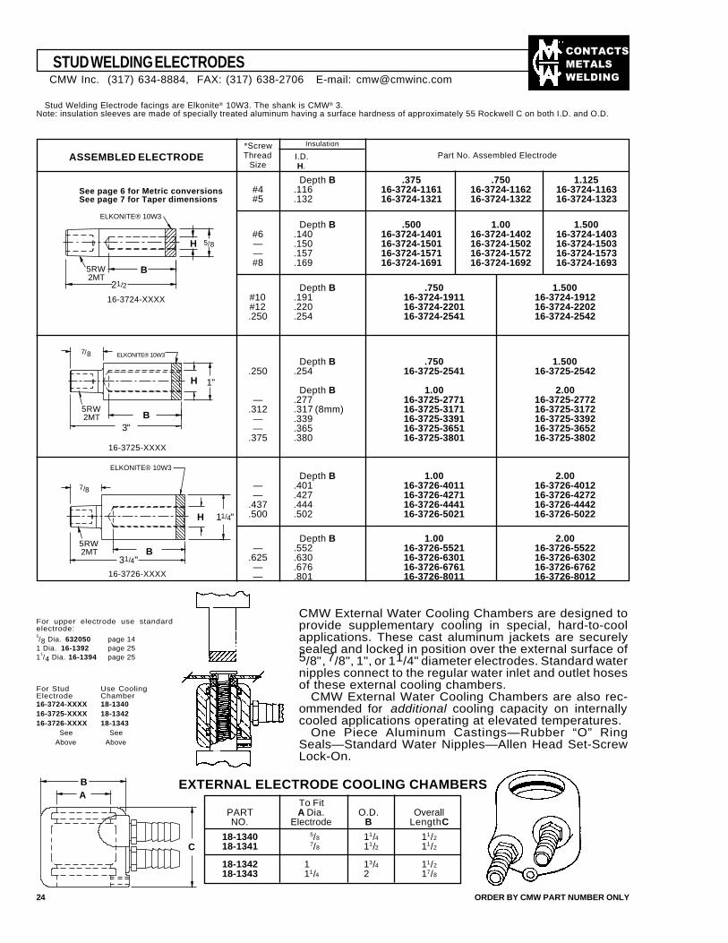
STUD WELDING ELECTRODES
24 ORDER BY CMW PART NUMBER ONLY
Stud Welding Electrode facings are Elkonite® 10W3. The shank is CMW® 3.Note: insulation sleeves are made of specially treated aluminum having a surface hardness of approximately 55 Rockwell C on both I.D. and O.D.
ASSEMBLED ELECTRODE
See page 6 for Metric conversionsSee page 7 for Taper dimensions
16-3724-XXXX
16-3726-XXXX
*ScrewThread
Size
Insulation
I.D.H.
Part No. Assembled Electrode
CMW External Water Cooling Chambers are designed toprovide supplementary cooling in special, hard-to-coolapplications. These cast aluminum jackets are securelysealed and locked in position over the external surface of5/8", 7/8", 1", or 11/4" diameter electrodes. Standard waternipples connect to the regular water inlet and outlet hosesof these external cooling chambers.
CMW External Water Cooling Chambers are also rec-ommended for additional cooling capacity on internallycooled applications operating at elevated temperatures.
One Piece Aluminum Castings—Rubber “O” RingSeals—Standard Water Nipples—Allen Head Set-ScrewLock-On.
EXTERNAL ELECTRODE COOLING CHAMBERS
For Stud Use CoolingElectrode Chamber16-3724-XXXX 18-134016-3725-XXXX 18-134216-3726-XXXX 18-1343
See SeeAbove Above
For upper electrode use standardelectrode:5/8 Dia. 632050 page 14
1 Dia. 16-1392 page 251
1/4 Dia. 16-1394 page 25
To FitPART A Dia. O.D. OverallNO. Electrode B Length C
18-1340 5/8 11/4 11/2
18-1341 7/8 11/2 11/2
18-1342 1 13/4 11/2
18-1343 11/4 2 17/8
CMW Inc. (317) 634-8884, FAX: (317) 638-2706 E-mail: [email protected]
5RW2MT
H
B
21/2
5/8
16-3725-XXXX
ELKONITE® 10W3
1"H
7/8 ELKONITE® 10W3
B5RW2MT
3"
5RW2MT
ELKONITE® 10W3
H 11/4"
Depth B .375 .750 1.125#4 .116 16-3724-1161 16-3724-1162 16-3724-1163#5 .132 16-3724-1321 16-3724-1322 16-3724-1323
Depth B .500 1.00 1.500#6 .140 16-3724-1401 16-3724-1402 16-3724-1403— .150 16-3724-1501 16-3724-1502 16-3724-1503— .157 16-3724-1571 16-3724-1572 16-3724-1573#8 .169 16-3724-1691 16-3724-1692 16-3724-1693
Depth B .750 1.500#10 .191 16-3724-1911 16-3724-1912#12 .220 16-3724-2201 16-3724-2202.250 .254 16-3724-2541 16-3724-2542
Depth B .750 1.500.250 .254 16-3725-2541 16-3725-2542
Depth B 1.00 2.00— .277 16-3725-2771 16-3725-2772
.312 .317 (8mm) 16-3725-3171 16-3725-3172— .339 16-3725-3391 16-3725-3392— .365 16-3725-3651 16-3725-3652
.375 .380 16-3725-3801 16-3725-3802
Depth B 1.00 2.00— .401 16-3726-4011 16-3726-4012— .427 16-3726-4271 16-3726-4272
.437 .444 16-3726-4441 16-3726-4442
.500 .502 16-3726-5021 16-3726-5022
Depth B 1.00 2.00— .552 16-3726-5521 16-3726-5522
.625 .630 16-3726-6301 16-3726-6302— .676 16-3726-6761 16-3726-6762— .801 16-3726-8011 16-3726-8012
B31/4"
BA
C
7/8
��������
�����
����
Water HoleOverall Weld Face ShankWeld Face Length Taper Dia. Depth Dia. Length
See page 6 for Metric conversions Part No. Material C D F G H T
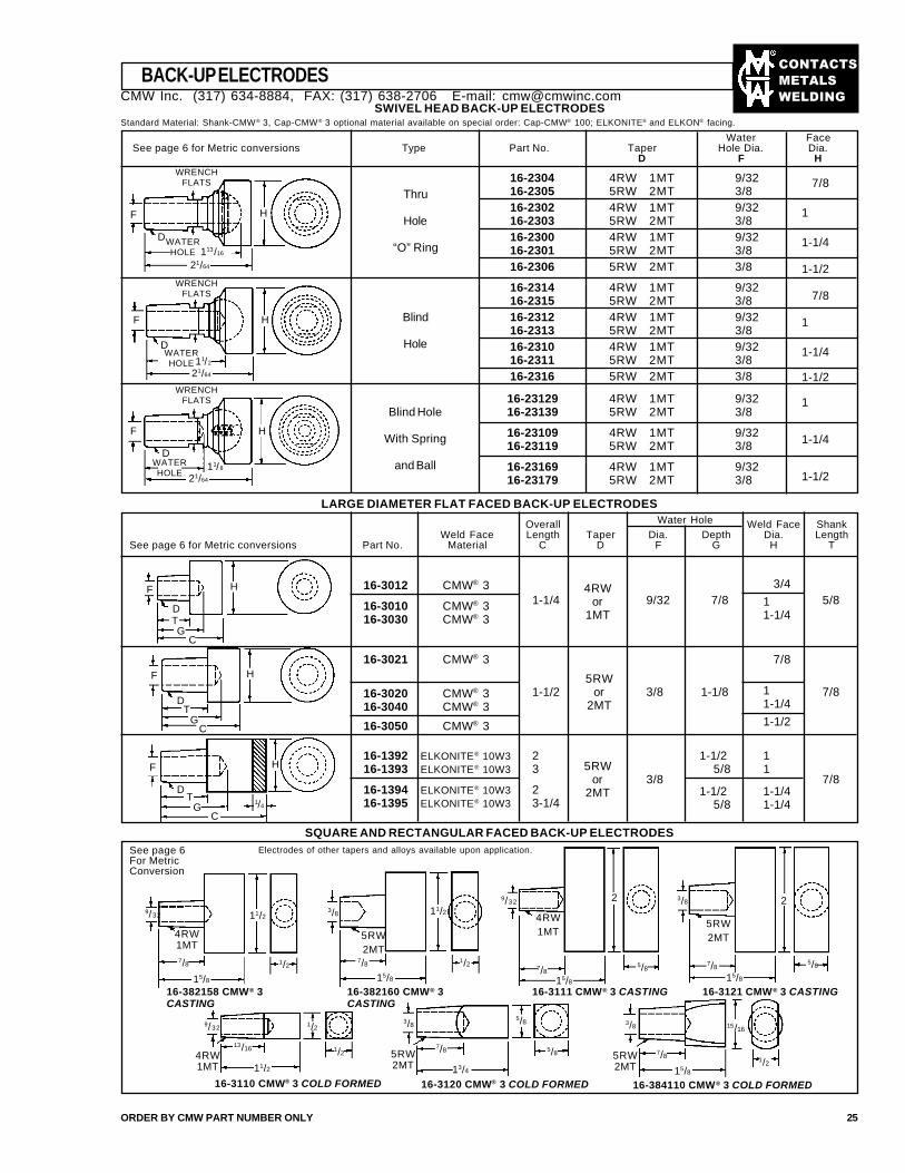
BACK-UP ELECTRODES
ORDER BY CMW PART NUMBER ONLY 25
SWIVEL HEAD BACK-UP ELECTRODESStandard Material: Shank-CMW® 3, Cap-CMW® 3 optional material available on special order: Cap-CMW® 100; ELKONITE® and ELKON® facing.
Water FaceSee page 6 for Metric conversions Type Part No. Taper Hole Dia. Dia.
D F H
Thru
Hole
“O” Ring
Blind
Hole
Blind Hole
With Spring
and Ball
16-2304 4RW 1MT 9/3216-2305 5RW 2MT 3/816-2302 4RW 1MT 9/3216-2303 5RW 2MT 3/816-2300 4RW 1MT 9/3216-2301 5RW 2MT 3/816-2306 5RW 2MT 3/8
16-2314 4RW 1MT 9/3216-2315 5RW 2MT 3/816-2312 4RW 1MT 9/3216-2313 5RW 2MT 3/816-2310 4RW 1MT 9/3216-2311 5RW 2MT 3/816-2316 5RW 2MT 3/8
16-23129 4RW 1MT 9/3216-23139 5RW 2MT 3/8
16-23109 4RW 1MT 9/3216-23119 5RW 2MT 3/8
16-23169 4RW 1MT 9/3216-23179 5RW 2MT 3/8
7/8
1
1-1/4
1-1/2
7/8
1
1-1/4
1-1/2
1
1-1/4
1-1/2
WRENCHFLATS
WRENCHFLATS
F
LARGE DIAMETER FLAT FACED BACK-UP ELECTRODES
16-3012 CMW® 3
16-3010 CMW® 316-3030 CMW® 3
16-3021 CMW® 3
16-3020 CMW® 316-3040 CMW® 3
16-3050 CMW® 3
16-1392 ELKONITE® 10W316-1393 ELKONITE® 10W3
16-1394 ELKONITE® 10W316-1395 ELKONITE® 10W3
1-1/4
1-1/2
23
23-1/4
9/32
3/8
3/8
7/8
1-1/8
1-1/2 1 5/8 1
1-1/2 1-1/4 5/8 1-1/4
7/8
7/8
5/8
7/8
11-1/4
1-1/2
3/4
11-1/4
4RWor
1MT
5RWor
2MT
5RWor
2MTD
SQUARE AND RECTANGULAR FACED BACK-UP ELECTRODESSee page 6For MetricConversion
Electrodes of other tapers and alloys available upon application.
5/8
1/2
H
WATERHOLE 113/16
21/64
D
F
11/2
D
21/64
H
WRENCHFLATS
H
11/8
21/64
D
F
WATERHOLE
WATERHOLE
F
TG
C
1/4
H
9/32
4RW1MT7/8
15/8
1/2
11/2
16-382158 CMW® 3CASTING
16-382160 CMW® 3CASTING
16-3111 CMW® 3 CASTING 16-3121 CMW® 3 CASTING
16-3110 CMW® 3 COLD FORMED 16-384110 CMW® 3 COLD FORMED16-3120 CMW® 3 COLD FORMED
3/8
5RW2MT
7/815/8
1/2
11/29/32
4RW1MT
7/815/8
5/8
2 3/8
5RW2MT
7/815/8
2
9/32
13/16
11/2
1/2
1/2
3/8
7/8
13/4
5/8
5/84RW1MT
5RW2MT
5RW2MT
3/8
7/8
15/8
15/16
F
DT
GC
F
DT
CG
H
H
CMW Inc. (317) 634-8884, FAX: (317) 638-2706 E-mail: [email protected]
��������
�����
����
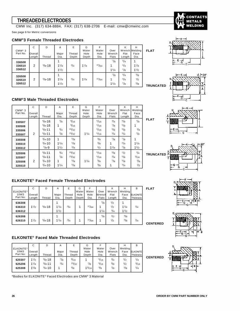
THREADED ELECTRODES
See page 6 for Metric conversions
CMW®3 Female Threaded Electrodes
26 ORDER BY CMW PART NUMBER ONLY
C D A E G F K HWater Water Over Wrench Welding
Overall Major Thread Hole Hole Wrench Flat FaceLength Thread Dia. Depth Depth Dia. Flats Length Dia.
1 7/8 3/4 12 5/8-18 11/4 3/4 11/4 37/64 1 3/4 11/4
11/2 11/4 7/8 11/2
1 7/8 3/4 3/8
2 5/8-18 11/4 3/4 11/4 37/64 1 3/4 1/2
11/2 11/4 7/8 5/8
CMW® 3Part No.
336508336510336512
326508326510326512
FLAT
TRUNCATED
CMW®3 Male Threaded Electrodes
CMW® 3Part No.
330507
330508
335506
335507
335508
335510
335512
325506
325507
325508
325510
C D A E G F K HWater Water Over Wrench Welding
Overall Major Thread Hole Hole Wrench Flat FaceLength Thread Dia. Depth Depth Dia. Flats Length Dia.
5/8-18 7/8 9/16 5/16 3/4 5/8 7/8
5/8-18 1 9/16 5/16 7/8 5/8 15/8-11 3/4 15/32 5/16 5/8 5/8 3/4
2 5/8-11 7/8 15/32 11/4 5/16 3/4 3/4 7/8
3/4-10 1 5/8 3/8 7/8 7/8 13/4-10 11/4 5/8 3/8 1 3/4 11/4
7/8-9 11/2 3/4 1/2 11/4 7/8 11/2
5/8-11 3/4 15/32 5/16 5/8 1/2 1/4
5/8-11 7/8 15/32 5/16 3/4 5/8 5/16
2 3/4-10 1 5/8 11/4 3/8 7/8 5/8 3/8
3/4-10 11/4 5/8 3/8 1 3/4 1/2
FLAT
TRUNCATED
ELKONITE® Faced Female Threaded Electrodes
ELKONITE®
10W3Part No.
636308
636310
636312
626308
626310
C D A E G F K H BWater Water Over Wrench Welding
Overall Major Thread Hole Hole Wrench Flat Face ELKONITELength Thread Dia. Depth Depth Dia. Flats Length Dia. Thickness
1 7/8 1/2 111/2 5/8-18 11/4 3/4 1 37/64 1 1/2 11/4 1/4
11/2 11/4 3/4 11/2
1 7/8 1/2 5/8
11/2 5/8-18 11/4 3/4 1 37/64 1 1/2 5/8 1/4
ELKONITE® Faced Male Threaded Electrodes
ELKONITE®
10W3Part No.
620307
625206
625308
C D A E G F H BWater Water Over Welding
Overall Major Thread Hole Hole Wrench Face ELKONITELength Thread Dia. Depth Depth Dia. Flats Dia. Thickness
11/2 5/8-18 7/8 9/16 1 5/16 3/4 1/2 1/4
11/4 5/8-11 3/4 15/32 7/8 5/16 5/8 1/2 3/16
15/8 3/4-10 1 5/8 13/16 3/8 7/8 5/8 1/4
FLAT
CENTERED
*Bodies for ELKONITE® Faced Electrodes are CMW® 3 Material
CENTERED
CMW Inc. (317) 634-8884, FAX: (317) 638-2706 E-mail: [email protected]
��������
�����
����
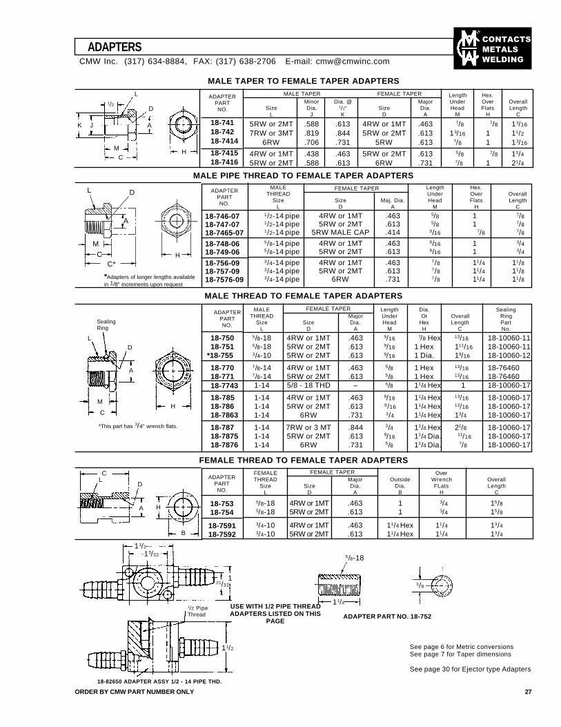
ADAPTERPARTNO.
18-74118-74218-7414
18-741518-7416
MALE Length Hex.THREAD Under Over Overall
Size Size Maj. Dia. Head Flats LengthL D A M H C
1/2-14 pipe 4RW or 1MT .463 5/8 1 7/81/2-14 pipe 5RW or 2MT .613 5/8 1 7/81/2-14 pipe 5RW MALE CAP .414 9/16 7/8 7/85/8-14 pipe 4RW or 1MT .463 9/16 1 3/45/8-14 pipe 5RW or 2MT .613 9/16 1 3/43/4-14 pipe 4RW or 1MT .463 7/8 11/4 11/83/4-14 pipe 5RW or 2MT .613 7/8 11/4 11/83/4-14 pipe 6RW .731 7/8 11/4 11/8
ADAPTERS
ORDER BY CMW PART NUMBER ONLY 27
MALE TAPER TO FEMALE TAPER ADAPTERSMALE TAPER FEMALE TAPER Length Hex.
Minor Dia. @ Major Under Over OverallSize Dia. 1/2" Size Dia. Head Flats Length
L J K D A M H C
5RW or 2MT .588 .613 4RW or 1MT .463 7/8 7/8 13/16
7RW or 3MT .819 .844 5RW or 2MT .613 13/16 1 11/26RW .706 .731 5RW .613 7/8 1 13/16
4RW or 1MT .438 .463 5RW or 2MT .613 5/8 7/8 13/45RW or 2MT .588 .613 6RW .731 7/8 1 21/4
11/2
15/32
1/2 PipeThread
11/2
18-82650 ADAPTER ASSY 1/2 - 14 PIPE THD.
5/8-18
11/4
3/8
USE WITH 1/2 PIPE THREADADAPTERS LISTED ON THIS
PAGEADAPTER PART NO. 18-752
See page 6 for Metric conversionsSee page 7 for Taper dimensions
See page 30 for Ejector type Adapters
MALE PIPE THREAD TO FEMALE TAPER ADAPTERS
FEMALE OverTHREAD Major Outside Wrench Overall
Size Size Dia. Dia. FLats LengthL D A B H C
5/8-18 4RW or 1MT .463 1 3/4 15/85/8-18 5RW or 2MT .613 1 3/4 15/8
3/4-10 4RW or 1MT .463 11/4 Hex 11/4 13/43/4-10 5RW or 2MT .613 11/4 Hex 11/4 13/4
FEMALE TAPER
FEMALE TAPER
FEMALE TAPER
MALE Length Dia. SealingTHREAD Major Under Or Overall Ring
Size Size Dia. Head Hex Length PartL D A M H C No.
5/8-18 4RW or 1MT .463 9/16 7/8 Hex 13/16 18-10060-115/8-18 5RW or 2MT .613 9/16 1 Hex 111/16 18-10060-113/4-10 5RW or 2MT .613 9/16 1 Dia. 19/16 18-10060-127/8-14 4RW or 1MT .463 5/8 1 Hex 13/16 18-764607/8-14 5RW or 2MT .613 5/8 1 Hex 13/16 18-764601-14 5/8 - 18 THD – 5/8 11/4 Hex 1 18-10060-17
1-14 4RW or 1MT .463 9/16 11/4 Hex 13/16 18-10060-171-14 5RW or 2MT .613 9/16 11/4 Hex 13/16 18-10060-171-14 6RW .731 3/4 11/4 Hex 13/4 18-10060-17
1-14 7RW or 3 MT .844 3/4 11/4 Hex 21/8 18-10060-171-14 5RW or 2MT .613 9/16 11/4 Dia. 11/16 18-10060-171-14 6RW .731 5/8 11/4 Dia. 7/8 18-10060-17
MALE THREAD TO FEMALE TAPER ADAPTERS
ADAPTERPARTNO.
18-75018-751
*18-755
18-77018-77118-7743
18-78518-78618-7863
18-78718-787518-7876
FEMALE THREAD TO FEMALE TAPER ADAPTERS
B
21/32
K J
MC
A
D
L1/2
H
*This part has 3/4" wrench flats.
HC
M
A
L
SealingRing
D
HA
DLC
1
ADAPTERPARTNO.
18-746-0718-747-0718-7465-07
18-748-0618-749-06
18-756-0918-757-0918-7576-09
CMW Inc. (317) 634-8884, FAX: (317) 638-2706 E-mail: [email protected]
ADAPTERPARTNO.
18-75318-754
18-759118-7592
A
DL
MC
C*
*Adapters of longer lengths availablein 1/8" increments upon request
H
��������
�����
����
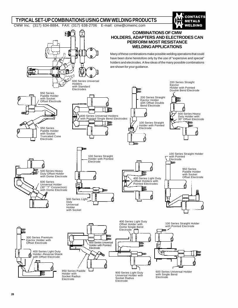
TYPICAL SET-UP COMBINATIONS USING CMW WELDING PRODUCTS
COMBINATIONS OF CMWHOLDERS, ADAPTERS AND ELECTRODES CAN
PERFORM MOST RESISTANCEWELDING APPLICATIONS
Many of these combinations make possible welding operations that couldhave been done heretofore only by the use of “expensive and special”holders and electrodes. A few ideas of the many possible combinationsare shown for your guidance.
600 Series UniversalHolderswith StandardElectrodes
950 SeriesPaddle Holderwith SocketOffset Electrode
950 SeriesPaddle Holderwith SocketTruncated ConeElectrode
600 Series Universal Holderswith Pointed Single Bend Electrodes
200 Series StraightEjectorHolder with PointedDouble Bend Electrode
500 Series HeavyDuty Holder with30" Offset Electrode
200 Series StraightEjector Holderwith Offset DoubleBend Electrode
100 Series StraightHolder with PointedElectrode
500 Series HeavyDuty Offset Holderwith Dome Electrode
600 SeriesUniversal Holder(30" “T” Connection)with Dome Electrode
100 Series StraightHolder with PointedElectrode
900 Series LightDutyUniversalHolderwith Socket
400 Series Light DutyOffset Holders withPointed Electrodes
100 Series Straight Holderwith PointedElectrode
950 SeriesPaddle Holderwith SocketOffset Electrode
300 Series PremiumEjector Holder withOffset Electrode
400 Series Light DutyHolder–Reverse Shankwith Offset Electrode
400 Series Light DutyOffset Holder withDome Single BendElectrode
900 Series Light DutyUniversal Holder withSocket RadiusElectrode
100 Series Straight Holderwith Pointed Electrode
600 Series Universal Holderwith Single BendElectrode
600 Series UniversalHolder with PointedElectrode
950 Series PaddleHolder withSocket RadiusElectrode
CMW Inc. (317) 634-8884, FAX: (317) 638-2706 E-mail: [email protected]
28
��������
�����
����
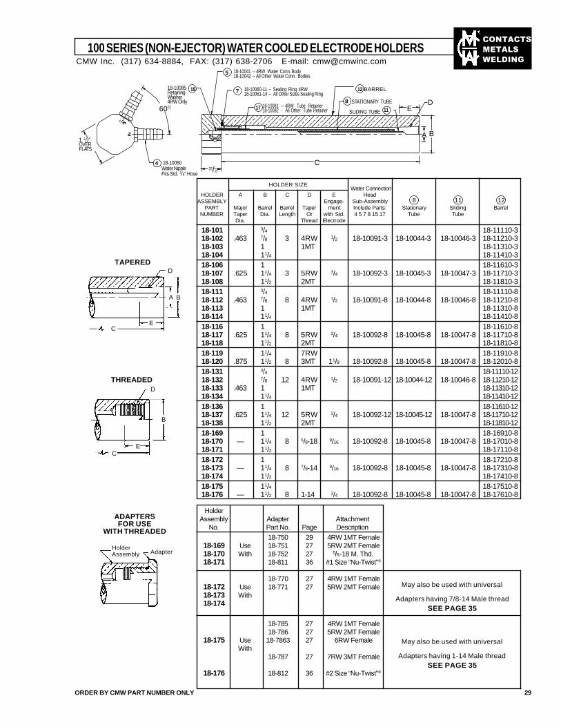
100 SERIES (NON-EJECTOR) WATER COOLED ELECTRODE HOLDERS
ORDER BY CMW PART NUMBER ONLY 29
TAPERED
THREADED
D
A B
EC
D
B
EC
ADAPTERSFOR USE
WITH THREADED
HolderAssembly Adapter
Water ConnectionHOLDER A B C D E Head
ASSEMBLY Engage- Sub-AssemblyPART Major Barrel Barrel Taper ment Include Parts: Stationary Sliding Barrel
NUMBER Taper Dia. Length Or with Std. 4 5 7 8 15 17 Tube TubeDia. Thread Electrode
18-101 3/4 18-11110-318-102 .463 7/8 3 4RW 1/2 18-10091-3 18-10044-3 18-10046-3 18-11210-318-103 1 1MT 18-11310-318-104 11/4 18-11410-318-106 1 18-11610-318-107 .625 11/4 3 5RW 3/4 18-10092-3 18-10045-3 18-10047-3 18-11710-318-108 11/2 2MT 18-11810-318-111 3/4 18-11110-818-112 .463 7/8 8 4RW 1/2 18-10091-8 18-10044-8 18-10046-8 18-11210-818-113 1 1MT 18-11310-818-114 11/4 18-11410-818-116 1 18-11610-818-117 .625 11/4 8 5RW 3/4 18-10092-8 18-10045-8 18-10047-8 18-11710-818-118 11/2 2MT 18-11810-818-119 11/4 7RW 18-11910-818-120 .875 11/2 8 3MT 11/8 18-10092-8 18-10045-8 18-10047-8 18-12010-818-131 3/4 18-11110-1218-132 7/8 12 4RW 1/2 18-10091-12 18-10044-12 18-10046-8 18-11210-1218-133 .463 1 1MT 18-11310-1218-134 11/4 18-11410-1218-136 1 18-11610-1218-137 .625 11/4 12 5RW 3/4 18-10092-12 18-10045-12 18-10047-8 18-11710-1218-138 11/2 2MT 18-11810-1218-169 1 18-16910-818-170 — 11/4 8 5/8-18 9/16 18-10092-8 18-10045-8 18-10047-8 18-17010-818-171 11/2 18-17110-818-172 1 18-17210-818-173 — 11/4 8 7/8-14 9/16 18-10092-8 18-10045-8 18-10047-8 18-17310-818-174 11/2 18-17410-818-175 11/4 18-17510-818-176 — 11/2 8 1-14 3/4 18-10092-8 18-10045-8 18-10047-8 18-17610-8
8 11 12
HOLDER SIZE
May also be used with universal
Adapters having 7/8-14 Male threadSEE PAGE 35
May also be used with universal
Adapters having 1-14 Male threadSEE PAGE 35
HolderAssembly Adapter Attachment
No. Part No. Page Description
18-750 29 4RW 1MT Female18-169 Use 18-751 27 5RW 2MT Female18-170 With 18-752 27 5/8-18 M. Thd.18-171 18-811 36 #1 Size “Nu-Twist”®
18-770 27 4RW 1MT Female18-172 Use 18-771 27 5RW 2MT Female18-173 With18-174
18-785 27 4RW 1MT Female18-786 27 5RW 2MT Female
18-175 Use 18-7863 27 6RW FemaleWith
18-787 27 7RW 3MT Female
18-176 18-812 36 #2 Size “Nu-Twist”®
CMW Inc. (317) 634-8884, FAX: (317) 638-2706 E-mail: [email protected]
60O
1 1/2"OVERFLATS
18-10050Water NippleFits Std. 3/8" Hose
4
18-10085RetainingWasher4RW Only
15
18-10041 -- 4RW Water Conn. Body18-10042 -- All Other Water Conn. Bodies
5
18-10060-11 -- Sealing Ring 4RW18-10061-14 -- All Other Sizes Sealing Ring7
18-10081 -- 4RW Tube Retainer18-10082 - All Other Tube Retainer
BARREL12
STATIONARY TUBE8
SLIDING TUBE17 11 E
D
BA
C25/32
��������
�����
����
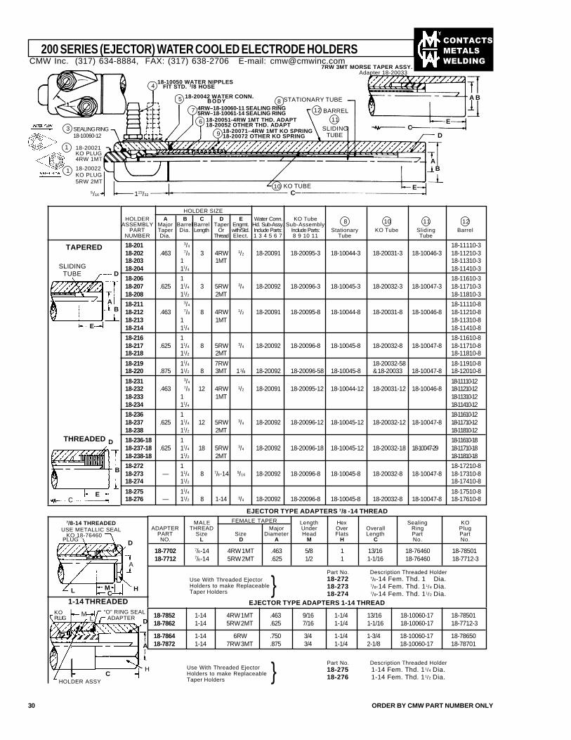
HOLDER A B C D E Water Conn. KO TubeASSEMBLY Major Barrel Barrel Taper Engmt. Hd. Sub-Assy. Sub-Assembly
PART Taper Dia. Length Or with/Std. Include Parts: Include Parts: Stationary KO Tube Sliding BarrelNUMBER Dia. Thread Elect. 1 3 4 5 6 7 8 9 10 11 Tube Tube
18-201 3/4 18-11110-318-202 .463 7/8 3 4RW 1/2 18-20091 18-20095-3 18-10044-3 18-20031-3 18-10046-3 18-11210-318-203 1 1MT 18-11310-318-204 11/4 18-11410-3
18-206 1 18-11610-318-207 .625 11/4 3 5RW 3/4 18-20092 18-20096-3 18-10045-3 18-20032-3 18-10047-3 18-11710-318-208 11/2 2MT 18-11810-3
18-211 3/4 18-11110-818-212 .463 7/8 8 4RW 1/2 18-20091 18-20095-8 18-10044-8 18-20031-8 18-10046-8 18-11210-818-213 1 1MT 18-11310-818-214 11/4 18-11410-8
18-216 1 18-11610-818-217 .625 11/4 8 5RW 3/4 18-20092 18-20096-8 18-10045-8 18-20032-8 18-10047-8 18-11710-818-218 11/2 2MT 18-11810-8
18-219 11/4 7RW 18-20032-58 18-11910-818-220 .875 11/2 8 3MT 11/8 18-20092 18-20096-58 18-10045-8 & 18-20033 18-10047-8 18-12010-8
18-231 3/4 18-11110-1218-232 .463 7/8 12 4RW 1/2 18-20091 18-20095-12 18-10044-12 18-20031-12 18-10046-8 18-11210-1218-233 1 1MT 18-11310-1218-234 11/4 18-11410-12
18-236 1 18-11610-1218-237 .625 11/4 12 5RW 3/4 18-20092 18-20096-12 18-10045-12 18-20032-12 18-10047-8 18-11710-1218-238 11/2 2MT 18-11810-12
18-236-18 1 18-11610-1818-237-18 .625 11/4 18 5RW 3/4 18-20092 18-20096-18 18-10045-12 18-20032-18 18-10047-29 18-11710-1818-238-18 11/2 2MT 18-11810-18
18-272 1 18-17210-818-273 — 11/4 8 7/8-14 9/16 18-20092 18-20096-8 18-10045-8 18-20032-8 18-10047-8 18-17310-818-274 11/2 18-17410-8
18-275 11/4 18-17510-818-276 — 11/2 8 1-14 3/4 18-20092 18-20096-8 18-10045-8 18-20032-8 18-10047-8 18-17610-8
200 SERIES (EJECTOR) WATER COOLED ELECTRODE HOLDERS
30 ORDER BY CMW PART NUMBER ONLY
7/8-14 THREADEDUSE METALLIC SEAL
HOLDER SIZE
8 10 11 12
TAPERED
THREADED
D
BA
E
SLIDINGTUBE
CE
B
D
EJECTOR TYPE ADAPTERS 7/8 -14 THREAD
MALE Length Hex Sealing KOADAPTER THREAD Major Under Over Overall Ring Plug
PART Size Size Diameter Head Flats Length Part PartNO. L D A M H C No. No.
18-7702 7/8-14 4RW 1MT .463 5/8 1 13/16 18-76460 18-7850118-7712 7/8-14 5RW 2MT .625 1/2 1 1-1/16 18-76460 18-7712-3
FEMALE TAPER
D
A
HMCL
KO 18-76460PLUG
EJECTOR TYPE ADAPTERS 1-14 THREAD
18-7852 1-14 4RW 1MT .463 9/16 1-1/4 13/16 18-10060-17 18-7850118-7862 1-14 5RW 2MT .625 7/16 1-1/4 1-1/16 18-10060-17 18-7712-3
18-7864 1-14 6RW .750 3/4 1-1/4 1-3/4 18-10060-17 18-7865018-7872 1-14 7RW 3MT .875 3/4 1-1/4 2-1/8 18-10060-17 18-78701
Part No. Description Threaded Holder18-272 7/8-14 Fem. Thd. 1 Dia.18-273 7/8-14 Fem. Thd. 11/4 Dia.18-274 7/8-14 Fem. Thd. 11/2 Dia.
Use With Threaded EjectorHolders to make ReplaceableTaper Holders }
1-14 THREADED
ML
HC
D
A
“O” RING SEALADAPTER
Use With Threaded EjectorHolders to make ReplaceableTaper Holders }
HOLDER ASSY
KOPLUG
Part No. Description Threaded Holder18-275 1-14 Fem. Thd. 11/4 Dia.18-276 1-14 Fem. Thd. 11/2 Dia.
5
418-10050 WATER NIPPLES
FIT STD. 3/8 HOSE
7
6 18-20051-4RW 1MT THD. ADAPT18-20052 OTHER THD. ADAPT
4RW–18-10060-11 SEALING RING5RW–18-10061-14 SEALING RING
9 18-20071–4RW 1MT KO SPRING18-20072 OTHER KO SPRING
1
8 STATIONARY TUBE
BARREL
SLIDINGTUBE
11
KO TUBE10
D
A B
EC
AB
E123/32
18-20042 WATER CONN.BODY
1
C
7RW 3MT MORSE TAPER ASSY.Adapter 18-20033
SEALING RING18-10060-12
3
18-20021KO PLUG4RW 1MT
18-20022KO PLUG5RW 2MT
5/16
12
CMW Inc. (317) 634-8884, FAX: (317) 638-2706 E-mail: [email protected]
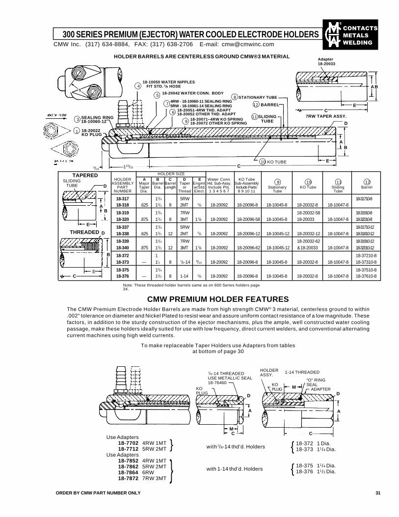
��������
�����
����
300 SERIES PREMIUM (EJECTOR) WATER COOLED ELECTRODE HOLDERS
ORDER BY CMW PART NUMBER ONLY 31
418-10050 WATER NIPPLES
FIT STD. 3/8 HOSE
5
9 18-20071–4RW KO SPRING18-20072 OTHER KO SPRING
6 18-20051-4RW THD. ADAPT18-20052 OTHER THD. ADAPT
7
18-20042 WATER CONN. BODY
4RW - 18-10060-11 SEALING RING5RW - 18-10061-14 SEALING RING
3 SEALING RING18-10060-12
1 18-20022KO PLUG
KO TUBE10
7RW TAPER ASSY.
Adapter18-20033
8 STATIONARY TUBE
BARREL12
HOLDER BARRELS ARE CENTERLESS GROUND CMW®3 MATERIAL
E
D
HOLDER A B C D E Water Conn. KO TubeASSEMBLY Major Barrel Barrel Taper Engmt. Hd. Sub-Assy. Sub-Assembly
PART Taper Dia. Length or w/Std. Include Pts. Include Parts: Stationary KO Tube Sliding BarrelNUMBER Dia. Thread Elect. 1 3 4 5 6 7 8 9 10 11 Tube Tube
18-317 11/4 5RW 18-31710-818-318 .625 11/2 8 2MT 3/4 18-20092 18-20096-8 18-10045-8 18-20032-8 18-10047-8
18-319 11/4 7RW 18-20032-58 18-31910-818-320 .875 11/2 8 3MT 11/8 18-20092 18-20096-58 18-10045-8 18-20033 18-10047-8 18-32010-8
18-337 11/4 5RW 18-31710-1218-338 .625 11/2 12 2MT 3/4 18-20092 18-20096-12 18-10045-12 18-20032-12 18-10047-8 18-31810-12
18-339 11/4 7RW 18-20032-62 18-31910-1218-340 .875 11/2 12 3MT 11/8 18-20092 18-20096-62 18-10045-12 & 18-20033 18-10047-8 18-32010-12
18-372 1 18-37210-818-373 — 1/
4 8 7/8-14 9/16 18-20092 18-20096-8 18-10045-8 18-20032-8 18-10047-8 18-37310-8
18-375 11/4 18-37510-818-376 — 11/2 8 1-14 3/4 18-20092 18-20096-8 18-10045-8 18-20032-8 18-10047-8 18-37610-8
8 10 11 12
HOLDER SIZE
Note: These threaded holder barrels same as on 600 Series holders page34.
CMW PREMIUM HOLDER FEATURESThe CMW Premium Electrode Holder Barrels are made from high strength CMW® 3 material, centerless ground to within.002" tolerance on diameter and Nickel Plated to resist wear and assure uniform contact resistance of a low magnitude. Thesefactors, in addition to the sturdy construction of the ejector mechanisms, plus the ample, well constructed water coolingpassage, make these holders ideally suited for use with low frequency, direct current welders, and conventional alternatingcurrent machines using high weld currents.
To make replaceable Taper Holders use Adapters from tablesat bottom of page 30
AB
E
SLIDINGTUBE
THREADED D
B
EC
CM
A
C
A
M ADAPTER
HOLDERASSY.
KOPLUG
7/8-14 THREADEDUSE METALLIC SEAL18-76460
KOPLUG
“O” RINGSEAL
1-14 THREADED
D D
Use Adapters18-7702 4RW 1MT18-7712 5RW 2MT
Use Adapters18-7852 4RW 1MT18-7862 5RW 2MT18-7864 6RW18-7872 7RW 3MT
} with 7/8-14 thd’d. Holders
with 1-14 thd’d. Holders
18-372 1 Dia.18-373 11/4 Dia.{18-375 11/4 Dia.18-376 11/2 Dia.{
SLIDINGTUBE
11
C123/325/16
CE
BA
BA
CMW Inc. (317) 634-8884, FAX: (317) 638-2706 E-mail: [email protected]
D
}
TAPERED
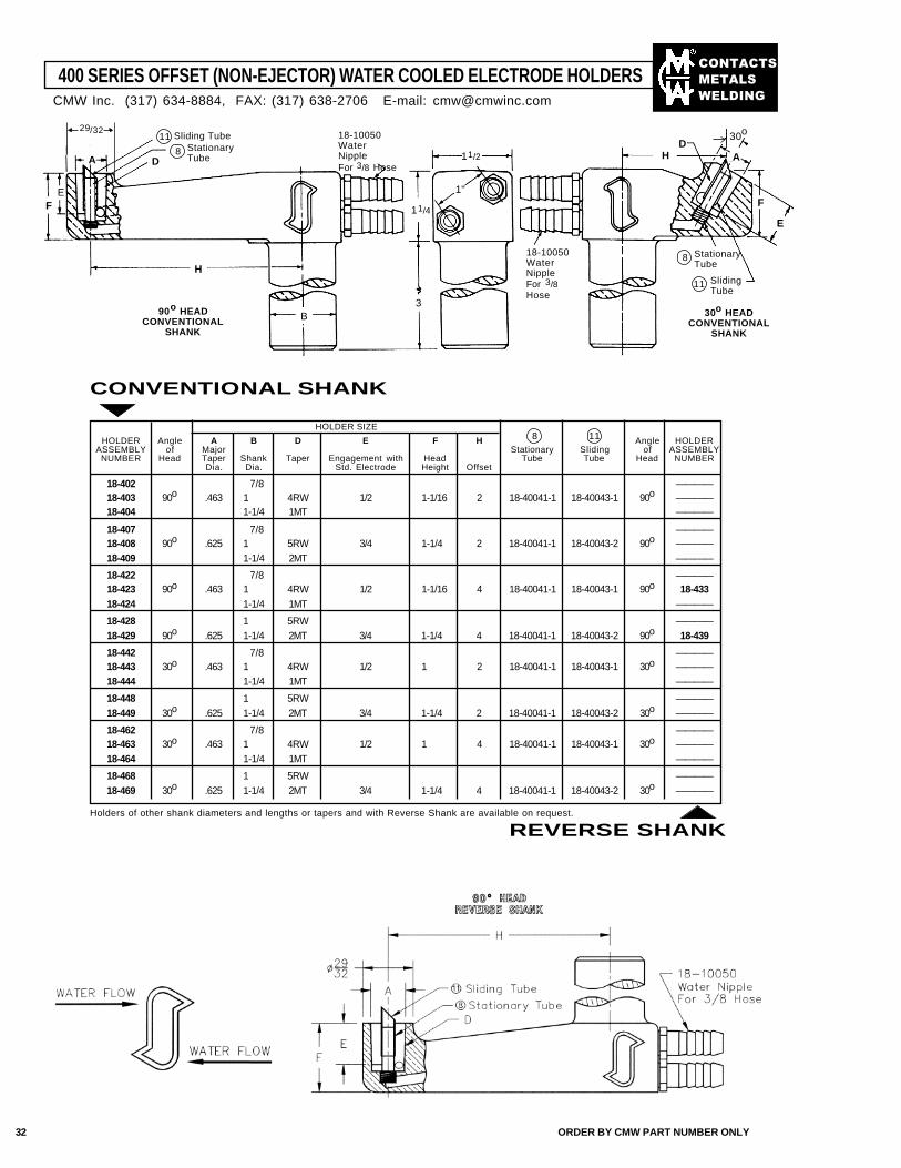
��������
�����
����
400 SERIES OFFSET (NON-EJECTOR) WATER COOLED ELECTRODE HOLDERS
B
H
D HD
A
E
F
11/2
3
11/4
1"
18-10050WaterNippleFor 3/8Hose
StationaryTube
8
18-10050WaterNippleFor 3/8 Hose
A
EF
11 Sliding TubeStationaryTube
8
90o HEADCONVENTIONAL
SHANK
30o HEADCONVENTIONAL
SHANK
CONVENTIONAL SHANK
HOLDER Angle A B D E F H Angle HOLDERASSEMBLY of Major Stationary Sliding of ASSEMBLY
NUMBER Head Taper Shank Taper Engagement with Head Tube Tube Head NUMBERDia. Dia. Std. Electrode Height Offset
18-402 7/8 ————18-403 90o .463 1 4RW 1/2 1-1/16 2 18-40041-1 18-40043-1 90o ————18-404 1-1/4 1MT ————
18-407 7/8 ————18-408 90o .625 1 5RW 3/4 1-1/4 2 18-40041-1 18-40043-2 90o ————18-409 1-1/4 2MT ————
18-422 7/8 ————18-423 90o .463 1 4RW 1/2 1-1/16 4 18-40041-1 18-40043-1 90o 18-43318-424 1-1/4 1MT ————
18-428 1 5RW ————18-429 90o .625 1-1/4 2MT 3/4 1-1/4 4 18-40041-1 18-40043-2 90o 18-439
18-442 7/8 ————18-443 30o .463 1 4RW 1/2 1 2 18-40041-1 18-40043-1 30o ————18-444 1-1/4 1MT ————
18-448 1 5RW ————18-449 30o .625 1-1/4 2MT 3/4 1-1/4 2 18-40041-1 18-40043-2 30o ————
18-462 7/8 ————18-463 30o .463 1 4RW 1/2 1 4 18-40041-1 18-40043-1 30o ————18-464 1-1/4 1MT ————
18-468 1 5RW ————18-469 30o .625 1-1/4 2MT 3/4 1-1/4 4 18-40041-1 18-40043-2 30o ————
HOLDER SIZE8 11
Holders of other shank diameters and lengths or tapers and with Reverse Shank are available on request.
REVERSE SHANK
30o29/32
CMW Inc. (317) 634-8884, FAX: (317) 638-2706 E-mail: [email protected]
SlidingTube
11
32 ORDER BY CMW PART NUMBER ONLY
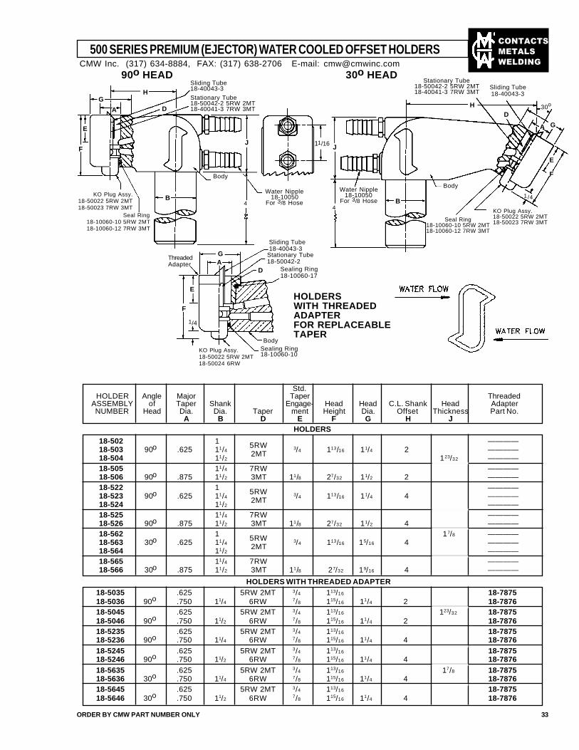
��������
�����
����
18-5035 .625 5RW 2MT 3/4 113/16 18-787518-5036 90o .750 11/4 6RW 7/8 115/16 11/4 2 18-787618-5045 .625 5RW 2MT 3/4 113/16 123/32 18-787518-5046 90o .750 11/2 6RW 7/8 115/16 11/4 2 18-787618-5235 .625 5RW 2MT 3/4 113/16 18-787518-5236 90o .750 11/4 6RW 7/8 115/16 11/4 4 18-787618-5245 .625 5RW 2MT 3/4 113/16 18-787518-5246 90o .750 11/2 6RW 7/8 115/16 11/4 4 18-787618-5635 .625 5RW 2MT 3/4 113/16 17/8 18-787518-5636 30o .750 11/4 6RW 7/8 115/16 11/4 4 18-787618-5645 .625 5RW 2MT 3/4 113/16 18-787518-5646 30o .750 11/2 6RW 7/8 115/16 11/4 4 18-7876
500 SERIES PREMIUM (EJECTOR) WATER COOLED OFFSET HOLDERS
ORDER BY CMW PART NUMBER ONLY 33
90o HEAD 30o HEADSliding Tube18-40043-3
Stationary Tube18-50042-2 5RW 2MT18-40041-3 7RW 3MT
Body
KO Plug Assy.18-50022 5RW 2MT18-50023 7RW 3MT
Seal Ring18-10060-10 5RW 2MT18-10060-12 7RW 3MT
HOLDERSWITH THREADEDADAPTERFOR REPLACEABLETAPER
Water Nipple18-10050
For 3/8 Hose
Body
KO Plug Assy.18-50022 5RW 2MT18-50023 7RW 3MTSeal Ring
18-10060-10 5RW 2MT18-10060-12 7RW 3MT
HG
A
E
F
B4
J
D
11/16
HD
A G
E
B
J
4
1/4
30o
Std.HOLDER Angle Major Taper Threaded
ASSEMBLY of Taper Shank Engage- Head Head C.L. Shank Head AdapterNUMBER Head Dia. Dia. Taper ment Height Dia. Offset Thickness Part No.
A B D E F G H J
18-502 1 5RW ————18-503 90o .625 11/4 3/4 113/16 11/4 2 ————18-504 11/2
2MT 123/32 ————18-505 11/4 7RW ————18-506 90o .875 11/2 3MT 11/8 27/32 11/2 2 ————18-522 1 5RW ————18-523 90o .625 11/4 3/4 113/16 11/4 4 ————18-524 11/2
2MT ————18-525 11/4 7RW ————18-526 90o .875 11/2 3MT 11/8 27/32 11/2 4 ————18-562 1 5RW 17/8 ————18-563 30o .625 11/4 3/4 113/16 15/16 4 ————18-564 11/2
2MT ————18-565 11/4 7RW ————18-566 30o .875 11/2 3MT 11/8 27/32 19/16 4 ————
HOLDERS
HOLDERS WITH THREADED ADAPTER
Sliding Tube18-40043-3
Stationary Tube18-50042-2
KO Plug Assy.18-50022 5RW 2MT18-50024 6RW
Sealing Ring18-10060-10
Body
GA
E
1/4
ThreadedAdapter
F
D
Stationary Tube18-50042-2 5RW 2MT18-40041-3 7RW 3MT
Sliding Tube18-40043-3
F
Sealing Ring18-10060-17
CMW Inc. (317) 634-8884, FAX: (317) 638-2706 E-mail: [email protected]
Water Nipple18-10050
For 3/8 Hose
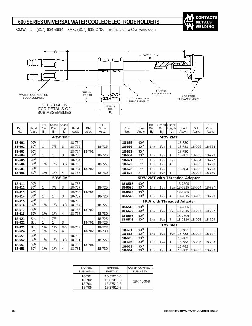
��������
�����
����
600 SERIES UNIVERSAL WATER COOLED ELECTRODE HOLDERS
34 ORDER BY CMW PART NUMBER ONLY
WATER CONNECTORSUB-ASSEMBLY ADAPTER
SUB-ASSEMBLY
BARRELSUB-ASSEMBLY
“T” CONNECTIONSUB-ASSEMBLY
SHANKLENGTH
L
SHANKDIA.Bs
BARREL DIA.B
b
15/8
SEE PAGE 35FOR DETAILS OFSUB-ASSEMBLIES
Bbl. Shank Shank “T”Part Head Dia. Dia. Length Head Bbl. Conn.No. Angle Bb Bs L Assy. Assy. Assy.
18-601 90o 18-76418-602 30o 1 7/8 3 18-765 18-725
18-603 90o 18-764 18-70118-604 30o 1 1 3 18-765 18-726
18-605 90o 18-76418-606 30o 11/4 11/4 31/2 18-765 18-727
18-607 90o 18-764 18-70218-608 30o 11/4 11/2 4 18-765 18-730
4RW 1MT
Bbl. Shank Shank “T”Part Head Dia. Dia. Length Head Bbl. Conn.No. Angle Bb Bs L Assy. Assy. Assy.
18-655 90o 18-78018-656 30o 11/2 11/4 4 18-781 18-705 18-728
18-653 90o 18-78018-654 30o 11/2 11/2 4 18-781 18-705 18-729
18-671 Str. 11/4 11/4 31/2 18-704 18-72718-672 Str. 11/2 11/2 4 18-705 18-729
18-673 Str. 11/2 11/4 18-784 18-705 18-72818-674 Str. 11/4 11/2 4 18-704 18-730
5RW 2MT
5RW 2MT
18-611 90o 18-76618-612 30o 1 7/8 3 18-767 18-725
18-613 90o 18-766 18-70118-614 30o 1 1 3 18-767 18-726
18-615 90o 18-76618-616 30o 11/4 11/4 31/2 18-767 18-727
18-617 90o 18-766 18-70218-618 30o 11/4 11/2 4 18-767 18-730
18-621 Str. 1 7/8 18-72518-622 Str. 1 1 3 18-701 18-726
18-623 Str. 11/4 11/4 31/2 18-768 18-72718-624 Str. 11/4 11/2 4 18-702 18-730
18-651 90o 18-78018-652 30o 11/4 11/4 31/2 18-781 18-727
18-657 90o 18-780 18-70418-658 30o 11/4 11/2 4 18-781 18-730
5RW 2MT with Threaded Adapter
18-6515 90o 18-780518-6525 30o 11/4 11/4 31/2 18-7815 18-704 18-727
18-6535 90o 18-780518-6545 30o 11/2 11/2 4 18-7815 18-705 18-729
6RW with Threaded Adapter
18-6516 90o 18-780618-6526 30o 11/4 11/4 31/2 18-7816 18-704 18-727
18-6536 90o 18-780618-6546 30o 11/2 11/2 4 18-7816 18-705 18-729
7RW 3MT18-661 90o 18-78218-662 30o 11/4 11/4 31/2 18-783 18-704 18-72718-665 90o 18-78218-666 30o 11/2 11/4 4 18-783 18-705 18-72818-663 90o 18-78218-664 30o 11/2 11/2 4 18-783 18-705 18-729
BARREL BARREL WATER CONNECT.SUB. ASSY. PART NO. SUB ASSY.
18-701 18-37210-818-702 18-37310-818-704 18-37510-818-705 18-37610-8
18-74000-8
8
CMW Inc. (317) 634-8884, FAX: (317) 638-2706 E-mail: [email protected]
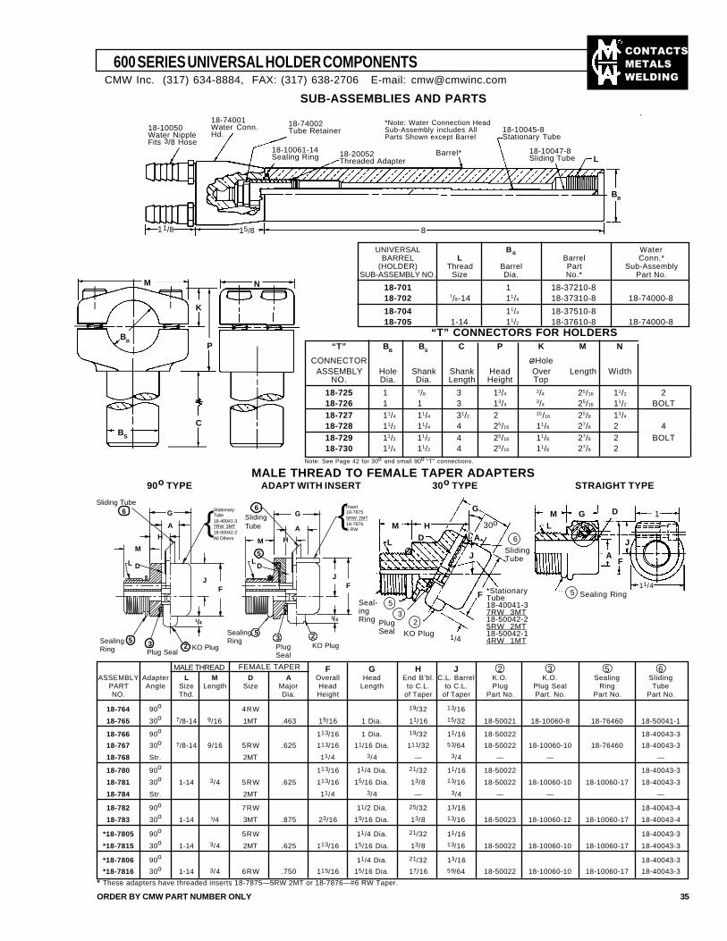
��������
�����
����
600 SERIES UNIVERSAL HOLDER COMPONENTS
ORDER BY CMW PART NUMBER ONLY 35
SUB-ASSEMBLIES AND PARTS
15/811/8
18-74001Water Conn.Hd.
18-74002Tube Retainer
18-10061-14Sealing Ring
18-10045-8Stationary Tube
18-10047-8Sliding Tube
Barrel*18-20052Threaded Adapter
*Note: Water Connection HeadSub-Assembly includes AllParts Shown except Barrel
L
BB
UNIVERSAL B B WaterBARREL L Barrel Conn.*
(HOLDER) Thread Barrel Part Sub-AssemblySUB-ASSEMBLY NO. Size Dia. No.* Part No.
18-701 1 18-37210-818-702 7/8-14 11/4 18-37310-8 18-74000-8
18-704 11/4 18-37510-818-705 1-14 11/2 18-37610-8 18-74000-8
“T” CONNECTORS FOR HOLDERS
M N
K
BS
BB
“T” BB
BS
C P K M N
CONNECTOR ØHoleASSEMBLY Hole Shank Shank Head Over Length Width
NO. Dia. Dia. Length Height Top
18-725 1 7/8 3 13/4 3/4 25/16 11/2 218-726 1 1 3 13/4
3/4 25/16 11/2 BOLT18-727 11/4 11/4 31/2 2 15/16 25/8 13/4
18-728 11/2 11/4 4 25/16 11/8 27/8 2 418-729 11/2 11/2 4 25/16 11/8 27/8 2 BOLT18-730 11/4 11/2 4 25/16 11/8 27/8 2
Note: See Page 42 for 30o and small 90o “T” connections.
MALE THREAD TO FEMALE TAPER ADAPTERS90o TYPE ADAPT WITH INSERT 30o TYPE STRAIGHT TYPE
DGML
AF
J
1
11/45 Sealing Ring
G
HDL
M
J
A
F
1/4
30o
6
SlidingTube
*StationaryTube18-40041-37RW 3MT18-50042-25RW 2MT18-50042-14RW 1MT
2
KO Plug
3PlugSeal
5Seal-ingRing
* These adapters have threaded inserts 18-7875—5RW 2MT or 18-7876—#6 RW Taper.
FEMALE TAPER
8
18-10050Water NippleFits 3/8 Hose
P
C
F G H J 2 3 5 6ASSEMBLY Adapter L M D A Overall Head End B’bl. C.L. Barrel K.O. K.O. Sealing Sliding
PART Angle Size Length Size Major Head Length to C.L. to C.L. Plug Plug Seal Ring TubeNO. Thd. Dia. Height of Taper of Taper Part No. Part. No. Part No. Part No.
18-764 90o 4RW 19/32 13/16
18-765 30o 7/8-14 9/16 1MT .463 19/16 1 Dia. 11/16 15/32 18-50021 18-10060-8 18-76460 18-50041-1
18-766 90o 113/16 1 Dia. 19/32 11/16 18-50022 18-40043-3
18-767 30o 7/8-14 9/16 5RW .625 113/16 11/16 Dia. 111/32 53/64 18-50022 18-10060-10 18-76460 18-40043-3
18-768 Str. 2MT 11/4 3/4 — 3/4 — — —
18-780 90o 113/16 11/4 Dia. 21/32 11/16 18-50022 18-40043-3
18-781 30o 1-14 3/4 5RW .625 113/16 15/16 Dia. 13/8 13/16 18-50022 18-10060-10 18-10060-17 18-40043-3
18-784 Str. 2MT 11/4 3/4 — 3/4 — — —
18-782 90o 7RW 11/2 Dia. 25/32 13/16 18-40043-4
18-783 30o 1-14 3/4 3MT .875 23/16 19/16 Dia. 13/8 13/16 18-50023 18-10060-12 18-10060-17 18-40043-4
*18-7805 90o 5RW 11/4 Dia. 21/32 11/16 18-40043-3
*18-7815 30o 1-14 3/4 2MT .625 113/16 15/16 Dia. 13/8 13/16 18-50022 18-10060-10 18-10060-17 18-40043-3
*18-7806 90o 11/4 Dia. 21/32 13/16 18-40043-3
*18-7816 30o 1-14 3/4 6RW .750 115/16 15/16 Dia. 17/16 59/64 18-50022 18-10060-10 18-10060-17 18-40043-3
CMW Inc. (317) 634-8884, FAX: (317) 638-2706 E-mail: [email protected]
MALE THREAD
Sliding Tube6 G
A
H
M
L D
JF
1/4
2 KO Plug3Plug Seal
5SealingRing
{StationaryTube18-40041-37RW 3MT18-50042-2All Others
SlidingTube
6
M
LD
5
G
A{
H
JF
1/4
5SealingRing 3
PlugSeal
2KO Plug
Insert18-78755RW 2MT18-78766 RW
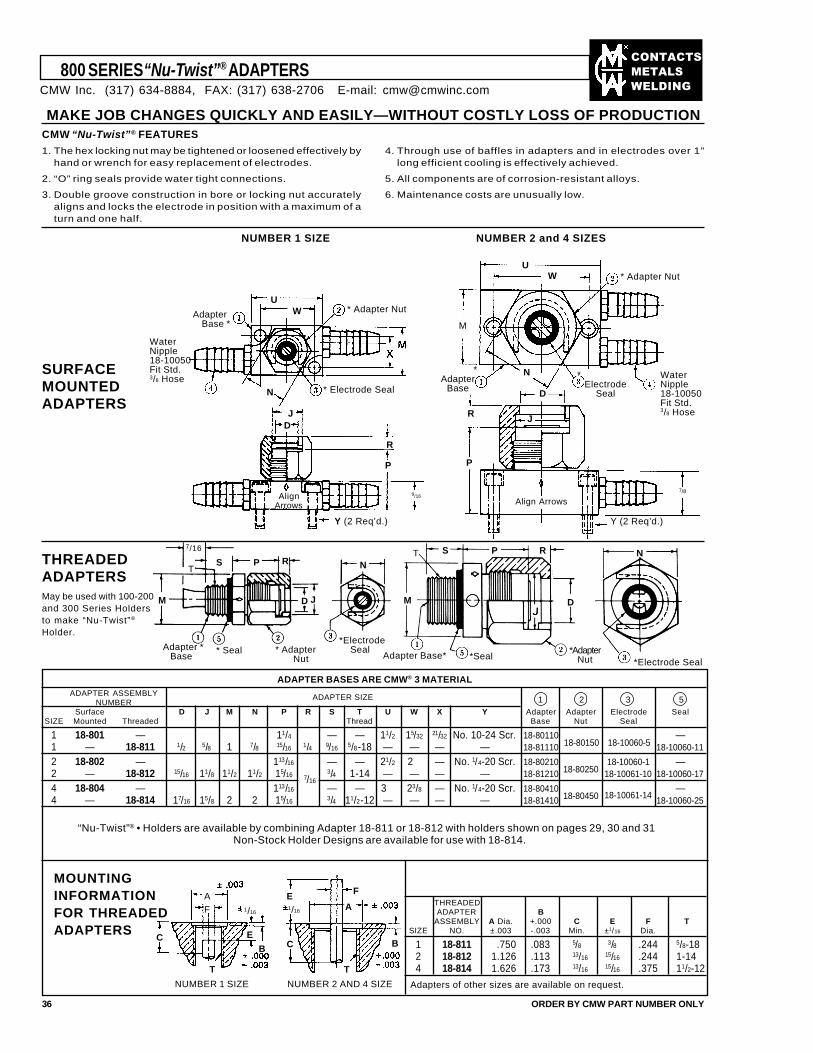
��������
�����
����
ADAPTER ASSEMBLYNUMBER
Surface D J M N P R S T U W X Y Adapter Adapter Electrode SealSIZE Mounted Threaded Thread Base Nut Seal
1 18-801 — 11/4 — — 11/2 15/32 21/32 No. 10-24 Scr. 18-80110 —1 — 18-811 1/2 5/8 1 7/8 15/16 1/4 9/16 5/8-18 — — — — 18-81110 18-10060-11
2 18-802 — 113/16 — — 21/2 2 — No. 1/4-20 Scr. 18-80210 18-10060-1 —2 — 18-812 15/16 11/8 11/2 11/2 15/16 3/4 1-14 — — — — 18-81210 18-80250 18-10061-10 18-10060-17
4 18-804 — 113/16 — — 3 23/8 — No. 1/4-20 Scr. 18-80410 —4 — 18-814 17/16 15/8 2 2 15/16 3/4 11/2-12 — — — — 18-81410 18-80450 18-10061-14 18-10060-25
800 SERIES “Nu-Twist”® ADAPTERS
MAKE JOB CHANGES QUICKLY AND EASILY—WITHOUT COSTLY LOSS OF PRODUCTIONCMW “Nu-Twist”® FEATURES
1. The hex locking nut may be tightened or loosened effectively byhand or wrench for easy replacement of electrodes.
2. “O” ring seals provide water tight connections.
3. Double groove construction in bore or locking nut accuratelyaligns and locks the electrode in position with a maximum of aturn and one half.
4. Through use of baffles in adapters and in electrodes over 1"long efficient cooling is effectively achieved.
5. All components are of corrosion-resistant alloys.
6. Maintenance costs are unusually low.
NUMBER 1 SIZE NUMBER 2 and 4 SIZES
SURFACEMOUNTEDADAPTERS
UW
N
JD
R
Y (2 Req’d.)
9/16
WaterNipple18-10050Fit Std.3/8 Hose
AlignArrows Align Arrows
Y (2 Req’d.)
* Adapter NutAdapter Base *
* Electrode Seal
UW * Adapter Nut
*Electrode
Seal
WaterNipple18-10050Fit Std.3/8 Hose
*Adapter
Base D
N
7/8
R
P
J
THREADEDADAPTERSMay be used with 100-200and 300 Series Holdersto make “Nu-Twist”®
Holder.
M
S P
D J
Adapter *Base
* Seal Adapter Base* *Seal
M
S P R
D
N7/16
RT
* AdapterNut
*Electrode Seal
N
*Electrode Seal*Adapter Nut
T
36 ORDER BY CMW PART NUMBER ONLY
MOUNTINGINFORMATIONFOR THREADEDADAPTERS
A
C
F
E
B C B
F
AE1/16
TT
1/16
NUMBER 2 AND 4 SIZENUMBER 1 SIZE
ADAPTER BASES ARE CMW® 3 MATERIAL
2 3 51ADAPTER SIZE
“Nu-Twist”® • Holders are available by combining Adapter 18-811 or 18-812 with holders shown on pages 29, 30 and 31Non-Stock Holder Designs are available for use with 18-814.
THREADEDADAPTER B
ASSEMBLY A Dia. +.000 C E F TSIZE NO. ±.003 -.003 Min. ±1/16 Dia.
1 18-811 .750 .083 5/8 3/8 .244 5/8-182 18-812 1.126 .113 13/16 15/16 .244 1-144 18-814 1.626 .173 13/16 15/16 .375 11/2-12
Adapters of other sizes are available on request.
7/16
18-80150 18-10060-5
M
CMW Inc. (317) 634-8884, FAX: (317) 638-2706 E-mail: [email protected]
P
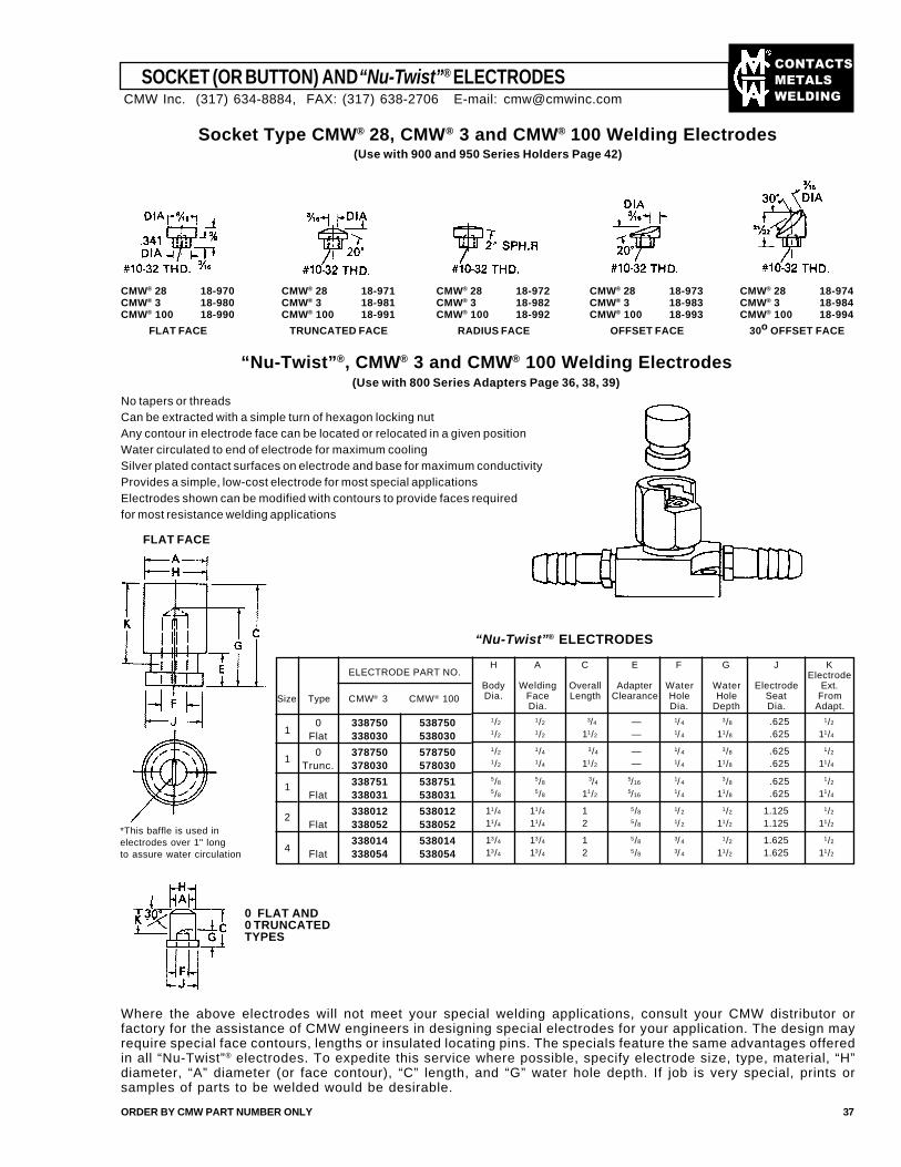
��������
�����
����
ORDER BY CMW PART NUMBER ONLY 37
SOCKET (OR BUTTON) AND “Nu-Twist”® ELECTRODES
Socket Type CMW® 28, CMW® 3 and CMW® 100 Welding Electrodes(Use with 900 and 950 Series Holders Page 42)
CMW® 28 18-974CMW® 3 18-984CMW® 100 18-994
30o OFFSET FACE
CMW® 28 18-973CMW® 3 18-983CMW® 100 18-993
OFFSET FACE
CMW® 28 18-972CMW® 3 18-982CMW® 100 18-992
RADIUS FACE
CMW® 28 18-971CMW® 3 18-981CMW® 100 18-991
TRUNCATED FACE
CMW® 28 18-970CMW® 3 18-980CMW® 100 18-990
FLAT FACE
“Nu-Twist”®, CMW® 3 and CMW® 100 Welding Electrodes(Use with 800 Series Adapters Page 36, 38, 39)
No tapers or threadsCan be extracted with a simple turn of hexagon locking nutAny contour in electrode face can be located or relocated in a given positionWater circulated to end of electrode for maximum coolingSilver plated contact surfaces on electrode and base for maximum conductivityProvides a simple, low-cost electrode for most special applicationsElectrodes shown can be modified with contours to provide faces requiredfor most resistance welding applications
*This baffle is used inelectrodes over 1" longto assure water circulation
FLAT FACE
0 FLAT AND0 TRUNCATEDTYPES
“Nu-Twist”® ELECTRODES
H A C E F G J KElectrode
Body Welding Overall Adapter Water Water Electrode Ext.Dia. Face Length Clearance Hole Hole Seat From
Dia. Dia. Depth Dia. Adapt.1/2 1/2 3/4 — 1/4 3/8 .625 1/2
1/2 1/2 11/2 — 1/4 11/8 .625 11/4
1/2 1/4 3/4 — 1/4 3/8 .625 1/2
1/2 1/4 11/2 — 1/4 11/8 .625 11/4
5/85/8
3/45/16
1/ 43/8 .625 1/2
5/85/8 11/2
5/161/ 4 11/8 .625 11/4
11/4 11/4 1 5/8 1/ 2 1/2 1.125 1/2
11/4 11/4 2 5/8 1/ 2 11/2 1.125 11/2
13/4 13/4 1 5/8 3/ 4 1/2 1.625 1/2
13/4 13/4 2 5/8 3/ 4 11/2 1.625 11/2
ELECTRODE PART NO.
Size Type CMW® 3 CMW® 100
0 338750 538750Flat 338030 538030
0 378750 578750Trunc. 378030 578030
338751 538751Flat 338031 538031
338012 538012Flat 338052 538052
338014 538014Flat 338054 538054
1
1
1
2
4
Where the above electrodes will not meet your special welding applications, consult your CMW distributor orfactory for the assistance of CMW engineers in designing special electrodes for your application. The design mayrequire special face contours, lengths or insulated locating pins. The specials feature the same advantages offeredin all “Nu-Twist”® electrodes. To expedite this service where possible, specify electrode size, type, material, “H”diameter, “A” diameter (or face contour), “C” length, and “G” water hole depth. If job is very special, prints orsamples of parts to be welded would be desirable.
CMW Inc. (317) 634-8884, FAX: (317) 638-2706 E-mail: [email protected]
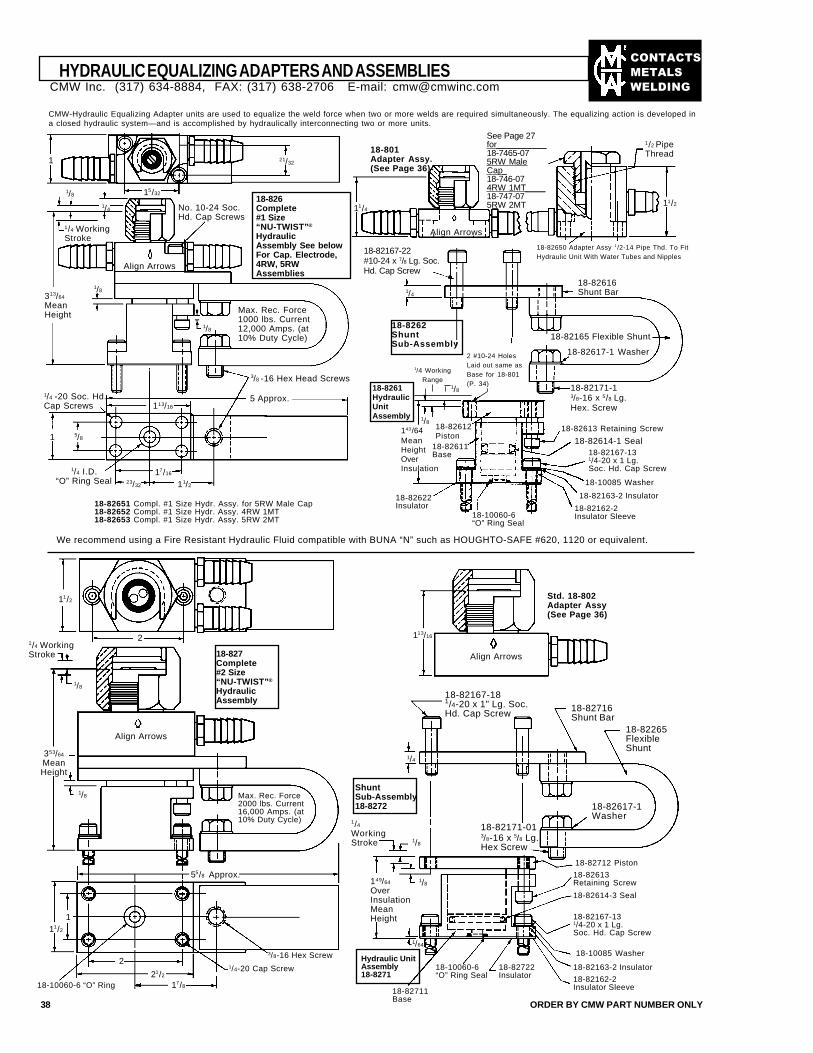
��������
�����
����
15/32
21/32
1/4
1/4 WorkingStroke
No. 10-24 Soc.Hd. Cap Screws
Align Arrows
1/8
1/8
1/4 -20 Soc. Hd.Cap Screws
5 Approx.113/16
17/16
11/223/32
1/4 I.D.“O” Ring Seal
18-82651 Compl. #1 Size Hydr. Assy. for 5RW Male Cap18-82652 Compl. #1 Size Hydr. Assy. 4RW 1MT18-82653 Compl. #1 Size Hydr. Assy. 5RW 2MT
Align Arrows
See Page 27for__________18-7465-075RW MaleCap_18-746-074RW 1MT____18-747-075RW 2MT
2 #10-24 HolesLaid out same asBase for 18-801(P. 34)
1/8
1/4 WorkingRange
18-82613 Retaining Screw
18-82614-1 Seal18-82167-131/4-20 x 1 Lg.Soc. Hd. Cap Screw
18-10085 Washer
18-82163-2 Insulator
18-82162-2Insulator Sleeve18-10060-6
“O” Ring Seal
18-82622Insulator
143/64MeanHeightOverInsulation
18-82612Piston
18-82611Base
We recommend using a Fire Resistant Hydraulic Fluid compatible with BUNA “N” such as HOUGHTO-SAFE #620, 1120 or equivalent.
18-826Complete#1 Size“NU-TWIST”®
HydraulicAssembly See belowFor Cap. Electrode,4RW, 5RWAssemblies
18-8262ShuntSub-Assembly
18-8261HydraulicUnitAssembly
CMW-Hydraulic Equalizing Adapter units are used to equalize the weld force when two or more welds are required simultaneously. The equalizing action is developed ina closed hydraulic system—and is accomplished by hydraulically interconnecting two or more units.
HYDRAULIC EQUALIZING ADAPTERS AND ASSEMBLIES
38 ORDER BY CMW PART NUMBER ONLY
1/8
Align Arrows
1/8
1
55/8 Approx.
1/4-20 Cap Screw
3/8-16 Hex Screw
18-10060-6 “O” Ring
Align Arrows
18-82167-181/4-20 x 1" Lg. Soc.Hd. Cap Screw 18-82716
Shunt Bar18-82265FlexibleShunt
18-82617-1Washer
1/8
18-82712 Piston
18-82171-013/8-16 x 5/8 Lg.Hex Screw
18-82613Retaining Screw
18-82614-3 Seal
18-82167-131/4-20 x 1 Lg.Soc. Hd. Cap Screw
18-10085 Washer
18-82163-2 Insulator
18-82162-2Insulator Sleeve
18-82722Insulator
18-10060-6“O” Ring Seal
18-82711Base
Std. 18-802Adapter Assy(See Page 36)
18-827Complete#2 Size“NU-TWIST”®
HydraulicAssembly
ShuntSub-Assembly18-8272
Hydraulic UnitAssembly18-8271
313/64
MeanHeight
5/81
3/8 -16 Hex Head Screws
1/8
Max. Rec. Force1000 lbs. Current12,000 Amps. (at10% Duty Cycle)
11/4
18-801Adapter Assy.(See Page 36)
18-82165 Flexible Shunt
18-82617-1 Washer
18-82616Shunt Bar
18-82650 Adapter Assy 1/2-14 Pipe Thd. To FitHydraulic Unit With Water Tubes and Nipples
11/2
1/2 PipeThread
18-82167-22#10-24 x 7/8 Lg. Soc.Hd. Cap Screw
1/4
1/8 18-82171-13/8-16 x 5/8 Lg.Hex. Screw
11/2
1/4 WorkingStroke
2
353/64
MeanHeight
2
21/2
11/2
17/8
1/4
149/64
OverInsulationMeanHeight
1/8
1/4
WorkingStroke
113/16
Max. Rec. Force2000 lbs. Current16,000 Amps. (at10% Duty Cycle)
1/64
1
CMW Inc. (317) 634-8884, FAX: (317) 638-2706 E-mail: [email protected]
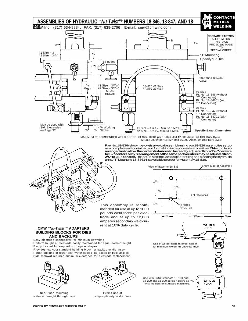
��������
�����
����
ASSEMBLIES OF HYDRAULIC “Nu-Twist”® NUMBERS 18-846, 18-847, AND 18-836
ORDER BY CMW PART NUMBER ONLY 39
3
#1 Size = 3"#2 Size = 31/2"
#1 Size = 313/64"#2 Size = 361/64"
MEANHEIGHT
1/4 WorkingStroke1/8
1/4
18-83603
May be used withStd. Electrodeson Page 37
B43/4
“T” MountingSpecify “B” Dim.
18-826 #1 Size18-827 #2 Size
18-83601 BleederValve
#1 SizePt. No. 18-846 (without“T” Connector)Pt. No. 18-84601 (with“T” Connector)
#2 SizePt. No. 18-847 (without“T” Connector)Pt. No. 18-84701 (with“T” Connector)
#1 Size—A = 11/32 Min. to 5 Max.#2 Size—A = 13/4 Min. to 6 Max.
MAXIMUM RECOMMENDED WELD FORCE: #1 Size 1000# per 18-826 Unit 12,000 Amps. @ 10% Duty Cycle #2 Size 2000# per 18-827 Unit 16,000 Amps. @ 10% Duty Cycle
Part No. 18-836 (shown below) is a typical assembly using two 18-826 assemblies set upas a complete self-contained unit for making two spot welds at one time. This unit is soarranged as to allow the center distances to be readily adjusted from 11/32" centersto 21/4" centers or by rearrangement of the same parts centers may be adjusted from21/4" to 31/2" centers. This set up also include facilities for filling and bleeding the hydraulicunits. “T” Mounting 18-83614 is available to order for Assembly 18-836.
This assembly is recom-mended for use at up to 1000pounds weld force per elec-trode and at up to 12,000amperes secondary weld cur-rent at 10% duty cycle.
Shunt Side of AssemblyView of Base for 18-836
13/4
17/16
1/4
11/4
5/85/8 31/2
4 Holes1/4-20Tap
¢ of Electrodes
CMW “Nu-Twist”® ADAPTERSBUILDING BLOCKS FOR DIES
AND BACKUPSEasy electrode changeover for minimum downtimeUniform height of electrode easily maintained for equal backup heightEasily located for stepped or irregular shapesProvides low-cost standard building block for backup or die insertPermit building of lower-cost water-cooled die bases or backup diesSide removal requires minimum clearance for electrode replacement
Near-flush mountingwater is brought through base
Permit use ofsimple plate-type die base
Use of welder horn as offset holderfor minimum welder throat clearance
Specify Exact Dimension
CONTACT FACTORYALL ITEMS ON
THIS PAGEPRICED and MADE
TOSPECIAL ORDER
CMW Inc. (317) 634-8884, FAX: (317) 638-2706 E-mail: [email protected]
Use with CMW standard 18-100 and18-200 and 18-300 series holders as “Nu-Twist” holders on standard machines.
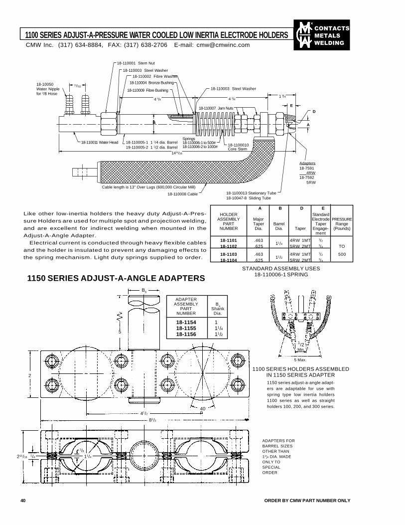
��������
�����
����
1100 SERIES ADJUST-A-PRESSURE WATER COOLED LOW INERTIA ELECTRODE HOLDERS
40 ORDER BY CMW PART NUMBER ONLY
Like other low-inertia holders the heavy duty Adjust-A-Pres-
sure Holders are used for multiple spot and projection welding,
and are excellent for indirect welding when mounted in the
Adjust-A-Angle Adapter.
Electrical current is conducted through heavy flexible cables
and the holder is insulated to prevent any damaging effects to
the spring mechanism. Light duty springs supplied to order.
A B D EHOLDER Standard
ASSEMBLY Major Electrode PRESSUREPART Taper Barrel Taper Range
NUMBER Dia. Dia. Taper Engage- (Pounds)ment
18-1101 .463 4RW 1MT 1/2
18-1102 .62511/4
5RW 2MT 3/4 TO
18-1103 .463 4RW 1MT 1/2 50018-1104 .625
11/25RW 2MT 3/4
STANDARD ASSEMBLY USES18-110006-1 SPRING1150 SERIES ADJUST-A-ANGLE ADAPTERS
1100 SERIES HOLDERS ASSEMBLEDIN 1150 SERIES ADAPTER1150 series adjust-a-angle adapt-ers are adaptable for use withspring type low inertia holders1100 series as well as straightholders 100, 200, and 300 series.
ADAPTERS FORBARREL SIZESOTHER THAN11¦4 DIA. MADEONLY TOSPECIALORDER
BS
5
2
81/2
215/16
40o41/2
1/8
1/4 11/4
5 Max.
ADAPTERASSEMBLY B
SPART Shank
NUMBER Dia.
18-1154 118-1155 11/418-1156 11/2
❤
CMW Inc. (317) 634-8884, FAX: (317) 638-2706 E-mail: [email protected]
18-110001 Stem Nut
18-110003 Steel Washer
18-110002 Fibre Washer
18-110009 Fibre Bushing 18-110003 Steel Washer
18-110004 Bronze Bushing
18-110007 Jam Nuts
18-10050Water Nipplefor 3/8 Hose
18-110011 Water Head 18-110005-1 1 1/4 dia. Barrel19-110005-2 1 1/2 dia. Barrel
Springs18-110006-1 to 500#18-110006-2 to 1000# 18-1100010
Core Stem
Adapters18-7591___4RW18-7592
5RW
18-110008 Cable 18-1100013 Stationary Tube18-10047-8 Sliding Tube
Cable length is 13" Over Lugs (600,000 Circular Mill)
31/32
4 3/4 4 3/41 3/4
1411/16
B
E
A
D
1/2Min.
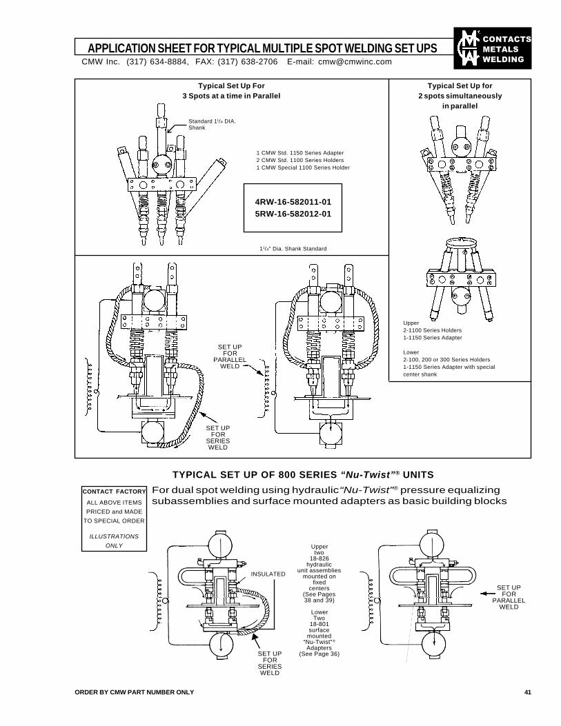
��������
�����
����
APPLICATION SHEET FOR TYPICAL MULTIPLE SPOT WELDING SET UPS
ORDER BY CMW PART NUMBER ONLY 41
INSULATED
Typical Set Up For3 Spots at a time in Parallel
Typical Set Up for2 spots simultaneously
in parallel
1 CMW Std. 1150 Series Adapter2 CMW Std. 1100 Series Holders1 CMW Special 1100 Series Holder
Upper2-1100 Series Holders1-1150 Series Adapter
Lower2-100, 200 or 300 Series Holders1-1150 Series Adapter with specialcenter shank
SET UPFOR
PARALLELWELD
SET UPFOR
SERIESWELD
SET UPFOR
SERIESWELD
SET UPFOR
PARALLELWELD
Uppertwo
18-826hydraulic
unit assembliesmounted on
fixedcenters
(See Pages38 and 39)
LowerTwo
18-801surface
mounted“Nu-Twist”®
Adapters(See Page 36)
TYPICAL SET UP OF 800 SERIES “Nu-Twist”® UNITS
For dual spot welding using hydraulic “Nu-Twist”® pressure equalizingsubassemblies and surface mounted adapters as basic building blocks
CONTACT FACTORY
ALL ABOVE ITEMS
PRICED and MADE
TO SPECIAL ORDER
ILLUSTRATIONS
ONLY
Standard 11/4 DIA.Shank
4RW-16-582011-015RW-16-582012-01
11/4" Dia. Shank Standard
CMW Inc. (317) 634-8884, FAX: (317) 638-2706 E-mail: [email protected]
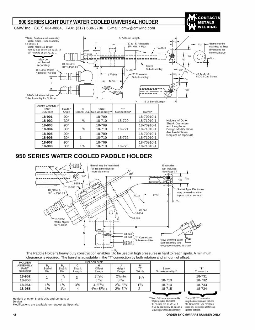
��������
�����
����
}
900 SERIES LIGHT DUTY WATER COOLED UNIVERSAL HOLDER
42 ORDER BY CMW PART NUMBER ONLY
**Note: Sold as a sub-assembly.Water nipple—tube assembly
18-90041-1Water nipple 18-10050#10-32 cap screw 18-82167-290o 1/8 pipe ell 18-71150-1
May bepurchasedseparately
}
Holders of OtherShank Diametersand Lengths orDesign ModificationsAre Available onRequest as Specials.
HOLDER ASSEMBLYPART Holder B Barrel “T”
NUMBER Angle Shank Dia. Sub-Assembly** Connection* Barrel*
18-901 90o 18-709 18-70910-118-902 30o 3/4 18-710 18-720 18-71010-118-903 90o 18-709 18-70910-118-904 30o 7/8 18-710 18-721 18-71010-118-905 90o 18-709 18-70910-118-906 30o 1 18-710 18-722 18-71010-118-907 90o 18-709 18-70910-118-908 30o 11/4 18-710 18-723 18-71010-1
The Paddle Holder’s heavy duty construction enables it to be used at high pressures in hard to reach spots. A minimumclearance is required. The barrel is adjustable in the “T” connection by both rotation and amount of offset.
HOLDERASSEMBLY B
BB
SC H J M
PART Barrel Shank Shank Offset Height “T” Barrel “T”NUMBER Dia. Dia. Length Range Range Width Sub-Assembly** Connector
18-952 7/8 33/8 to 21/16 to 18-73118-953 1 53/32 31/16 18-713 18-73218-954 11/4 11/4 31/2 4-523/32 23/4-33/4 13/4 18-714 18-73318-955 11/2 11/2 4 47/32-515/16 27/8-37/8 2 18-715 18-734
HOLDER SIZE
}
**Note: Sold as a sub-assemblyWater nipples 18-1005090
o 1/8 pipe ells 18-71150-1
# 10-32 cap screw 18-82167-2May be purchased separately.
Holders of other Shank Dia. and Lengths orDesignModifications are available on request as Specials.
3 11/21
950 SERIES WATER COOLED PADDLE HOLDER
CMW Inc. (317) 634-8884, FAX: (317) 638-2706 E-mail: [email protected]
These 30o “T” connectormay be interchanged with the90
o Universal Type “T” Conn.
page 35. See page 28 for sug-gested set ups.
5 3/4 Barrel Length
9/16*
1/16*
13/16
5/8
11/32
15/16
3/32
5 7/8 Barrel Length
11/32 Drill
1 1/2 Dia. "T" ConnectorSub-Assembly
BarrelSub-Assembly
*Barrel may bemachined to thesedimensions formore clearance
9/32
3/4 Dia.
18-82167-2#10-32 Cap Screw
18-10050 WaterNipple for 3/8 Hose
18-90041-1 Water NippleTube Assembly for 3/8 Hose
18-71150-190o 1/8 Pipe Ell
B Dia.
30o
CL to CL Adjustable11/8 Min. 4 Max.
{ }18-95318-952
9/16*
129/32
17/3223/32
9/32
18-954
18-955
18-71318-714
18-715
R 11/2
BB
JM
30o
18-71150-190o 1/8 Pipe Ell
18-10050Water Nipplefor 1/8 Hose
18-734
18-732
18-733
18-731
"T" ConnectionSub-assemblies
C
*Barrel may be machined to this dimension for more clearance
ElectrodesNot IncludedSee Page 37
Socket Type Electrodesmay be used on eithertop or bottom surface
View showing barrelSub-assembly andelectrode reversed in shank
H
BS
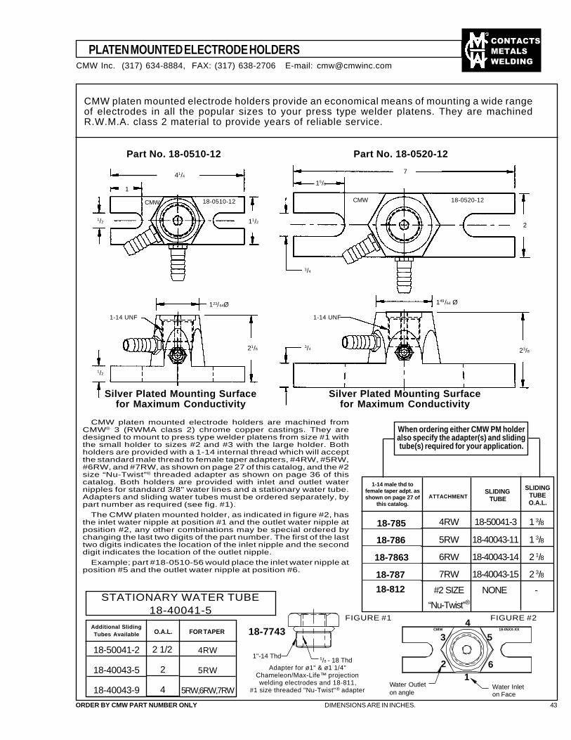
��������
�����
����
PLATEN MOUNTED ELECTRODE HOLDERS
ORDER BY CMW PART NUMBER ONLY DIMENSIONS ARE IN INCHES. 43
CMW platen mounted electrode holders provide an economical means of mounting a wide rangeof electrodes in all the popular sizes to your press type welder platens. They are machinedR.W.M.A. class 2 material to provide years of reliable service.
Part No. 18-0510-12 Part No. 18-0520-12
41/4
1/2
1
CMW 18-0510-12
11/2
1/2
21/8
1-14 UNF
123/64Ø
3/4
149/64 Ø
23/8
3/4
15/8
7
2
18-0520-12CMW
CMW platen mounted electrode holders are machined fromCMW® 3 (RWMA class 2) chrome copper castings. They aredesigned to mount to press type welder platens from size #1 withthe small holder to sizes #2 and #3 with the large holder. Bothholders are provided with a 1-14 internal thread which will acceptthe standard male thread to female taper adapters, #4RW, #5RW,#6RW, and #7RW, as shown on page 27 of this catalog, and the #2size “Nu-Twist”® threaded adapter as shown on page 36 of thiscatalog. Both holders are provided with inlet and outlet waternipples for standard 3/8" water lines and a stationary water tube.Adapters and sliding water tubes must be ordered separately, bypart number as required (see fig. #1).
The CMW platen mounted holder, as indicated in figure #2, hasthe inlet water nipple at position #1 and the outlet water nipple atposition #2, any other combinations may be special ordered bychanging the last two digits of the part number. The first of the lasttwo digits indicates the location of the inlet nipple and the seconddigit indicates the location of the outlet nipple.
Example; part #18-0510-56 would place the inlet water nipple atposition #5 and the outlet water nipple at position #6.
When ordering either CMW PM holderalso specify the adapter(s) and slidingtube(s) required for your application.
FIGURE #1
Silver Plated Mounting Surfacefor Maximum Conductivity
Silver Plated Mounting Surfacefor Maximum Conductivity
4RW 18-50041-3 1 3/8
5RW 18-40043-11 1 3/8
6RW 18-40043-14 2 1/8
7RW 18-40043-15 2 3/8
#2 SIZE NONE -
“Nu-Twist”®
ATTACHMENTSLIDING
TUBE
STATIONARY WATER TUBE18-40041-5
Additional SlidingTubes Available
18-50041-2
18-40043-5
18-40043-9
2 1/2
2
4
4RW
5RW
5RW,6RW,7RW
O.A.L. FOR TAPER 18-7743
Adapter for ø1" & ø1 1/4"Chameleon/Max-Life™ projectionwelding electrodes and 18-811,
#1 size threaded "Nu-Twist"® adapter
CMW Inc. (317) 634-8884, FAX: (317) 638-2706 E-mail: [email protected]
1-14 UNF
1-14 male thd tofemale taper adpt. asshown on page 27 of
this catalog.
SLIDINGTUBEO.A.L.
18-785
18-786
18-7863
18-787
18-812
1"-14 Thd 5/8 - 18 Thd
CMW 18-05XX-XX
Water Outleton angle
Water Inleton Face
FIGURE #2
12
3
4
5
6
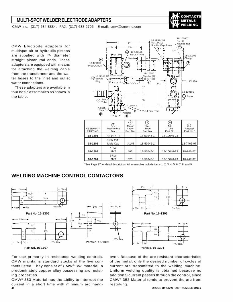
��������
�����
����
Major Stat. Adj.ASSEMBLY Attachment Taper Tube Tube AdapterPART NO. Dia. Part No. Part No. Part No. Part No.*
18-1201 1/2-14 NPT — 18-50046-1 18-10046-23 —
5RW 2MT18-1202 Male Cap .4145 18-50046-1 — 18-7465-07
4RW18-1203 1MT .463 18-50046-1 18-10046-23 18-746-07
5RW18-1204 2MT .625 18-50046-1 18-10046-23 18-747-07
MULTI-SPOT WELDER ELECTRODE ADAPTERS
44 ORDER BY CMW PART NUMBER ONLY
CMW Elect rode adapters formultispot air or hydraulic pistonsare supplied with 3/4 diameterstraight piston rod ends. Theseadapters are equipped with meansfor attaching the welding cablefrom the transformer and the wa-ter hoses to the inlet and outletwater connections.
These adapters are available infour basic assemblies as shown inthe table.
D
A
31/4
17/83/4
11/2
3¦4
31/2
7/8
1"
3/4 I.D.5/8 Dia.
11/8 Dia.
18-120106INSULATION
18-82168-021/8 PipePlug
Stat.Tube
Adjust.Tube
Adapter1/2-14 Pipe Thd.
18-120101
Barrel
18-120102Clamp
18-120105INSULATION
18-10050Nipples (2)For 3/8 Hose
18-82167-165/16-18x1LgSoc Hd Cap Screw
18-1000075/16 -18Knurled Nut
911
10D
A
*See Page 27 for detail description. All assemblies include items 1, 2, 3, 4, 5, 6, 7, 8, and 9.
WELDING MACHINE CONTROL CONTACTORS
15/16 3/4
3/8
3/8
11/1611/32 Dia.
11/16
13/4 1
13/8
7/16 Dia.
7/16
1/2
5/8 1/2
11/2
1/2
1/2 11/2
3/87/8 11/32 Dia.
1
7/8
25/64 Dia.
13/16
11/4
7/16
15/32
3/8
11/4
15/8
7/16
7/16
11/4
11/32 Dia.3/87/8
7/8
Part No. 16-1309
Part No. 16-1307
Part No. 16-1306 Part No. 16-1303
Part No. 16-1304
For use primarily in resistance welding controls.CMW maintains standard stocks of the five con-tacts listed. They consist of CMW® 353 material, apredominately copper alloy possessing arc resist-ing properties.CMW® 353 Material has the ability to interrupt thecurrent in a short time with minimum arc hang-
over. Because of the arc resistant characteristicsof the metal, only the desired number of cycles ofcurrent are transmitted to the welding machine.Uniform welding quality is obtained because noadditional current passes through the control, sinceCMW® 353 Material tends to prevent the arc fromrestriking.
CMW Inc. (317) 634-8884, FAX: (317) 638-2706 E-mail: [email protected]
5/16
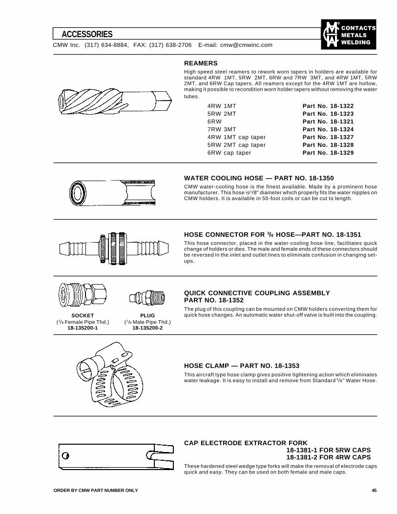
��������
�����
����
ACCESSORIES
ORDER BY CMW PART NUMBER ONLY 45
REAMERSHigh speed steel reamers to rework worn tapers in holders are available forstandard 4RW 1MT, 5RW 2MT, 6RW and 7RW 3MT, and 4RW 1MT, 5RW2MT. and 6RW Cap tapers. All reamers except for the 4RW 1MT are hollow,making it possible to recondition worn holder tapers without removing the watertubes.
4RW 1MT Part No. 18-13225RW 2MT Part No. 18-13236RW Part No. 18-13217RW 3MT Part No. 18-13244RW 1MT cap taper Part No. 18-13275RW 2MT cap taper Part No. 18-13286RW cap taper Part No. 18-1329
WATER COOLING HOSE — PART NO. 18-1350CMW water-cooling hose is the finest available. Made by a prominent hosemanufacturer. This hose is 3/8" diameter which properly fits the water nipples onCMW holders. It is available in 50-foot coils or can be cut to length.
HOSE CONNECTOR FOR 3/8 HOSE—PART NO. 18-1351This hose connector, placed in the water-cooling hose line, facilitates quickchange of holders or dies. The male and female ends of these connectors shouldbe reversed in the inlet and outlet lines to eliminate confusion in changing set-ups.
QUICK CONNECTIVE COUPLING ASSEMBLYPART NO. 18-1352The plug of this coupling can be mounted on CMW holders converting them forquick hose changes. An automatic water shut-off valve is built into the coupling.
HOSE CLAMP — PART NO. 18-1353This aircraft type hose clamp gives positive tightening action which eliminateswater leakage. It is easy to install and remove from Standard 3/8" Water Hose.
CAP ELECTRODE EXTRACTOR FORK18-1381-1 FOR 5RW CAPS18-1381-2 FOR 4RW CAPS
These hardened steel wedge type forks will make the removal of electrode capsquick and easy. They can be used on both female and male caps.
PLUG(1/8 Male Pipe Thd.)
18-135200-2
SOCKET(1/8 Female Pipe Thd.)
18-135200-1
CMW Inc. (317) 634-8884, FAX: (317) 638-2706 E-mail: [email protected]
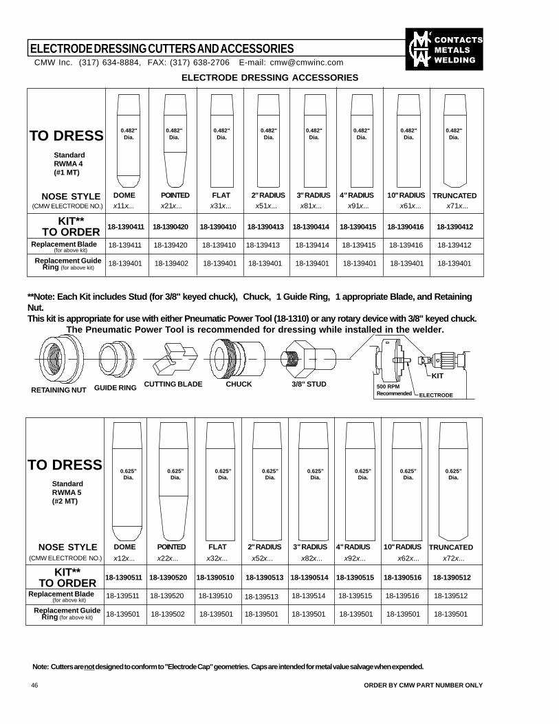
��������
�����
����
ELECTRODE DRESSING ACCESSORIES
TO DRESSStandardRWMA 4(#1 MT)
NOSE STYLE DOME POINTED FLAT 2" RADIUS 3" RADIUS 4" RADIUS 10" RADIUS TRUNCATED (CMW ELECTRODE NO.) x11x... x21x... x31x... x71x...
KIT**TO ORDER
Replacement Blade(for above kit)
Replacement GuideRing (for above kit)
18-139401
18-139420 18-139410 18-139413 18-139414 18-139415 18-139416 18-139412
18-139402 18-139401 18-139401 18-139401 18-139401 18-139401 18-139401
18-139411
18-1390411 18-1390420 18-1390410 18-1390413 18-1390414 18-1390415 18-1390416 18-1390412
Note: Cutters are not designed to conform to "Electrode Cap" geometries. Caps are intended for metal value salvage when expended.
46 ORDER BY CMW PART NUMBER ONLY
ELECTRODE DRESSING CUTTERS AND ACCESSORIES
0.482"Dia.
0.482"Dia.
0.482"Dia.
0.482"Dia.
0.482"Dia.
0.482"Dia.
0.482"Dia.
0.482"Dia.
CMW Inc. (317) 634-8884, FAX: (317) 638-2706 E-mail: [email protected]
x51x... x81x... x91x... x61x...
TO DRESSStandardRWMA 5(#2 MT)
NOSE STYLE DOME POINTED FLAT 2" RADIUS 3" RADIUS 4" RADIUS 10" RADIUS TRUNCATED (CMW ELECTRODE NO.) x12x... x22x... x32x... x72x...
KIT**TO ORDER
Replacement Blade(for above kit)
Replacement GuideRing (for above kit) 18-139501
18-139520 18-139510 18-139513 18-139514 18-139515 18-139516 18-139512
18-139502 18-139501 18-139501 18-139501 18-139501 18-139501 18-139501
18-139511
18-1390511 18-1390520 18-1390510 18-1390513 18-1390514 18-1390515 18-1390516 18-1390512
x52x... x82x... x92x... x62x...
0.625"Dia.
0.625"Dia.
0.625"Dia.
0.625"Dia.
0.625"Dia.
0.625"Dia.
0.625"Dia.
0.625"Dia.
**Note: Each Kit includes Stud (for 3/8" keyed chuck), Chuck, 1 Guide Ring, 1 appropriate Blade, and RetainingNut.This kit is appropriate for use with either Pneumatic Power Tool (18-1310) or any rotary device with 3/8" keyed chuck.
The Pneumatic Power Tool is recommended for dressing while installed in the welder.
RETAINING NUT GUIDE RING CUTTING BLADE CHUCK 3/8" STUD 500 RPMRecommended ELECTRODE
KIT
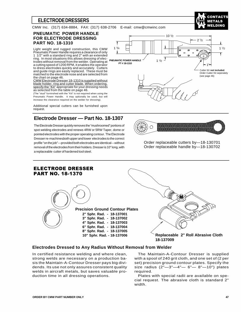
��������
�����
����
ELECTRODE DRESSERS
ORDER BY CMW PART NUMBER ONLY 47
Electrode Dresser — Part No. 18-1307The Electrode Dresser quickly removes the “mushroomed” portions ofspot welding electrodes and renews 4RW or 5RW Taper, dome orpointed electrodes with the proper operating contour. The ElectrodeDresser re-machines both upper and lower electrodes to the correctprofile “on the job”—provided both electrodes are identical—withoutremoval of the electrodes from their holders. Dresser is 10" long, witha replaceable cutter of hardened tool steel.
Order replaceable cutters by—18-130701Order replaceable handle by—18-130702
Electrodes Dressed to Any Radius Without Removal from Welder
In certified resistance welding and where clean,strong welds are necessary on a production ba-sis the Maintain-A-Contour Dresser pays big divi-dends. Its use not only assures consistent qualitywelds in aircraft metals, but saves valuable pro-duction time in all dressing operations.
The Maintain-A-Contour Dresser is suppliedwith a spool of 240 grit cloth, and one set of (2 perset) precision ground contour plates. Specify thesize radius (2"—3"—4"— 6"— 8"—10") platesrequired.
Plates with special radii are available on spe-cial request. The abrasive cloth is standard 2"width.
����������������
����������������
CMW Inc. (317) 634-8884, FAX: (317) 638-2706 E-mail: [email protected]
Replaceable 2" Roll Abrasive Cloth18-137009
Precision Ground Contour Plates2" Sphr. Rad. - 18-1370013" Sphr. Rad. - 18-1370024" Sphr. Rad. - 18-1370036" Sphr. Rad. - 18-1370048" Sphr. Rad. - 18-13700510" Sphr. Rad. - 18-137006
PNEUMATIC POWER HANDLEFOR ELECTRODE DRESSINGPART NO. 18-1310Light weight and rugged construction, this CMWPneumatic Power Handle requires a clearance of only1 1/2" with a standard ring and 2" with an extendedring. In most situations this allows dressing of elec-trodes without removal from the welder. Operating ata cutting speed of 1200 RPM, it enables the operatorto dress electrodes quickly and accurately. Cuttersand guide rings are easily replaced. These must bematched to the electrode nose and are selected fromthe chart on page 46.CMW Electrode Dresser 18-1310 is supplied withoutblade holder, ring and cutter blade. When ordering,specify the "Kit" appropriate for your dressing needsas selected from the table on page 46.(The "stud" furninshed with the "Kit" is not required when using thePneumatic Power Handle. It may optionally be used, but willincrease the clearance required on the welder for dressing).
Additional special cutters can be furnished uponrequest.
10 1/2
1 3/4
2 1/2
1 1/2
1 1/21"
PNEUMATIC POWER HANDLEPT # 18-1310
Cutter Kit not included.Order Cutter Kit seperately(see page 46)
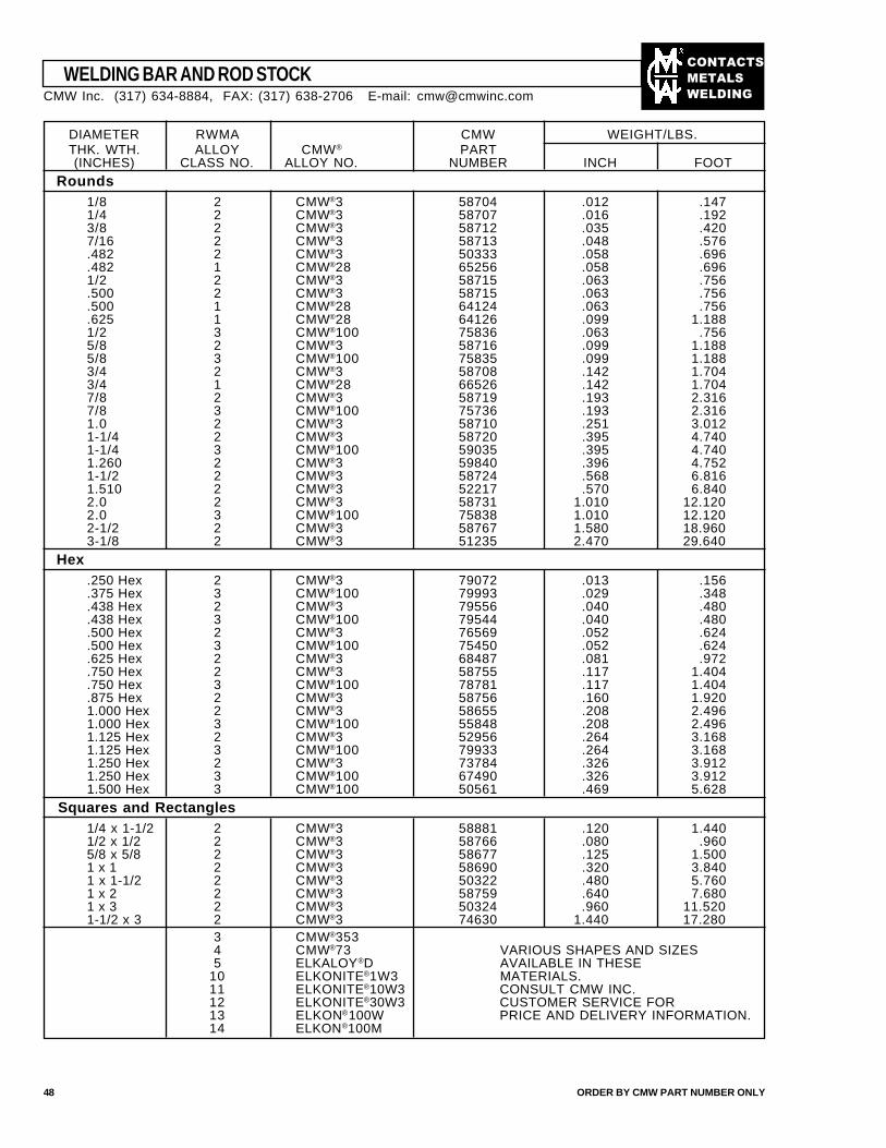
��������
�����
����
DIAMETER RWMA CMW WEIGHT/LBS.THK. WTH. ALLOY CMW® PART(INCHES) CLASS NO. ALLOY NO. NUMBER INCH FOOT
Rounds1/8 2 CMW®3 58704 .012 .1471/4 2 CMW®3 58707 .016 .1923/8 2 CMW®3 58712 .035 .4207/16 2 CMW®3 58713 .048 .576.482 2 CMW®3 50333 .058 .696.482 1 CMW®28 65256 .058 .6961/2 2 CMW®3 58715 .063 .756.500 2 CMW®3 58715 .063 .756.500 1 CMW®28 64124 .063 .756.625 1 CMW®28 64126 .099 1.1881/2 3 CMW®100 75836 .063 .7565/8 2 CMW®3 58716 .099 1.1885/8 3 CMW®100 75835 .099 1.1883/4 2 CMW®3 58708 .142 1.7043/4 1 CMW®28 66526 .142 1.7047/8 2 CMW®3 58719 .193 2.3167/8 3 CMW®100 75736 .193 2.3161.0 2 CMW®3 58710 .251 3.0121-1/4 2 CMW®3 58720 .395 4.7401-1/4 3 CMW®100 59035 .395 4.7401.260 2 CMW®3 59840 .396 4.7521-1/2 2 CMW®3 58724 .568 6.8161.510 2 CMW®3 52217 .570 6.8402.0 2 CMW®3 58731 1.010 12.1202.0 3 CMW®100 75838 1.010 12.1202-1/2 2 CMW®3 58767 1.580 18.9603-1/8 2 CMW®3 51235 2.470 29.640
Hex.250 Hex 2 CMW®3 79072 .013 .156.375 Hex 3 CMW®100 79993 .029 .348.438 Hex 2 CMW®3 79556 .040 .480.438 Hex 3 CMW®100 79544 .040 .480.500 Hex 2 CMW®3 76569 .052 .624.500 Hex 3 CMW®100 75450 .052 .624.625 Hex 2 CMW®3 68487 .081 .972.750 Hex 2 CMW®3 58755 .117 1.404.750 Hex 3 CMW®100 78781 .117 1.404.875 Hex 2 CMW®3 58756 .160 1.9201.000 Hex 2 CMW®3 58655 .208 2.4961.000 Hex 3 CMW®100 55848 .208 2.4961.125 Hex 2 CMW®3 52956 .264 3.1681.125 Hex 3 CMW®100 79933 .264 3.1681.250 Hex 2 CMW®3 73784 .326 3.9121.250 Hex 3 CMW®100 67490 .326 3.9121.500 Hex 3 CMW®100 50561 .469 5.628
Squares and Rectangles1/4 x 1-1/2 2 CMW®3 58881 .120 1.4401/2 x 1/2 2 CMW®3 58766 .080 .9605/8 x 5/8 2 CMW®3 58677 .125 1.5001 x 1 2 CMW®3 58690 .320 3.8401 x 1-1/2 2 CMW®3 50322 .480 5.7601 x 2 2 CMW®3 58759 .640 7.6801 x 3 2 CMW®3 50324 .960 11.5201-1/2 x 3 2 CMW®3 74630 1.440 17.280
3 CMW®3534 CMW®73 VARIOUS SHAPES AND SIZES5 ELKALOY®D AVAILABLE IN THESE
10 ELKONITE®1W3 MATERIALS.11 ELKONITE®10W3 CONSULT CMW INC.12 ELKONITE®30W3 CUSTOMER SERVICE FOR13 ELKON®100W PRICE AND DELIVERY INFORMATION.14 ELKON®100M
WELDING BAR AND ROD STOCK
48 ORDER BY CMW PART NUMBER ONLY
CMW Inc. (317) 634-8884, FAX: (317) 638-2706 E-mail: [email protected]
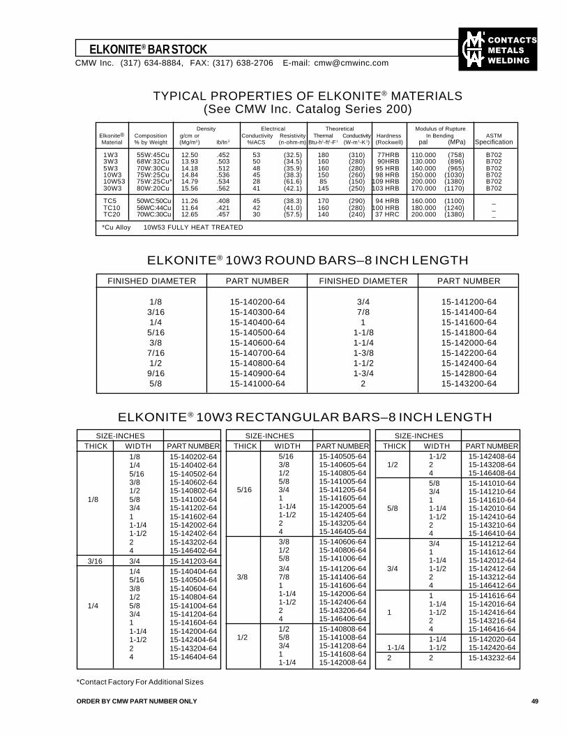
��������
�����
����
ELKONITE® BAR STOCK
ORDER BY CMW PART NUMBER ONLY 49
Density Electrical Theoretical Modulus of RuptureElkonite® Composition g/cm or Conductivity Resistivity Thermal Conductivity Hardness In Bending ASTMMaterial % by Weight (Mg/m3) Ib/In3 %IACS (n-ohm-m) Btu-h1-ft1-F1 (W-m1-K1) (Rockwell) pal (MPa) Specification
1W3 55W:45Cu 12.50 .452 53 (32.5) 180 (310) 77HRB 110.000 (758) B7023W3 68W:32Cu 13.93 .503 50 (34.5) 160 (280) 90HRB 130.000 (896) B7025W3 70W:30Cu 14.18 .512 48 (35.9) 160 (280) 95 HRB 140.000 (965) B70210W3 75W:25Cu 14.84 .536 45 (38.3) 150 (260) 98 HRB 150.000 (1030) B70210W53 75W:25Cu* 14.79 .534 28 (61.6) 85 (150) 109 HRB 200.000 (1380) B70230W3 80W:20Cu 15.56 .562 41 (42.1) 145 (250) 103 HRB 170.000 (1170) B702
TC5 50WC:50Cu 11.26 .408 45 (38.3) 170 (290) 94 HRB 160.000 (1100) _TC10 56WC:44Cu 11.64 .421 42 (41.0) 160 (280) 100 HRB 180.000 (1240) _TC20 70WC:30Cu 12.65 .457 30 (57.5) 140 (240) 37 HRC 200.000 (1380) _
*Cu Alloy 10W53 FULLY HEAT TREATED
SIZE-INCHESTHICK WIDTH PART NUMBER
1/8 15-140202-641/4 15-140402-645/16 15-140502-643/8 15-140602-641/2 15-140802-64
1/8 5/8 15-141002-643/4 15-141202-641 15-141602-641-1/4 15-142002-641-1/2 15-142402-642 15-143202-644 15-146402-64
3/16 3/4 15-141203-641/4 15-140404-645/16 15-140504-643/8 15-140604-641/2 15-140804-64
1/4 5/8 15-141004-643/4 15-141204-641 15-141604-641-1/4 15-142004-641-1/2 15-142404-642 15-143204-644 15-146404-64
ELKONITE® 10W3 ROUND BARS–8 INCH LENGTH
1-1/2 15-142408-641/2 2 15-143208-64
4 15-146408-645/8 15-141010-643/4 15-141210-641 15-141610-64
5/8 1-1/4 15-142010-641-1/2 15-142410-642 15-143210-644 15-146410-643/4 15-141212-641 15-141612-641-1/4 15-142012-64
3/4 1-1/2 15-142412-642 15-143212-644 15-146412-641 15-141616-641-1/4 15-142016-64
1 1-1/2 15-142416-642 15-143216-644 15-146416-641-1/4 15-142020-64
1-1/4 1-1/2 15-142420-642 2 15-143232-64
SIZE-INCHESTHICK WIDTH PART NUMBER
SIZE-INCHESTHICK WIDTH PART NUMBER
ELKONITE® 10W3 RECTANGULAR BARS–8 INCH LENGTH
FINISHED DIAMETER PART NUMBER FINISHED DIAMETER PART NUMBER
1/8 15-140200-64 3/4 15-141200-64 3/16 15-140300-64 7/8 15-141400-64 1/4 15-140400-64 1 15-141600-64 5/16 15-140500-64 1-1/8 15-141800-64 3/8 15-140600-64 1-1/4 15-142000-64 7/16 15-140700-64 1-3/8 15-142200-64 1/2 15-140800-64 1-1/2 15-142400-64 9/16 15-140900-64 1-3/4 15-142800-64 5/8 15-141000-64 2 15-143200-64
TYPICAL PROPERTIES OF ELKONITE® MATERIALS(See CMW Inc. Catalog Series 200)
5/16 15-140505-643/8 15-140605-641/2 15-140805-645/8 15-141005-64
5/16 3/4 15-141205-641 15-141605-641-1/4 15-142005-641-1/2 15-142405-642 15-143205-644 15-146405-643/8 15-140606-641/2 15-140806-645/8 15-141006-643/4 15-141206-64
3/8 7/8 15-141406-641 15-141606-641-1/4 15-142006-641-1/2 15-142406-642 15-143206-644 15-146406-641/2 15-140808-64
1/2 5/8 15-141008-643/4 15-141208-641 15-141608-641-1/4 15-142008-64
*Contact Factory For Additional Sizes
CMW Inc. (317) 634-8884, FAX: (317) 638-2706 E-mail: [email protected]
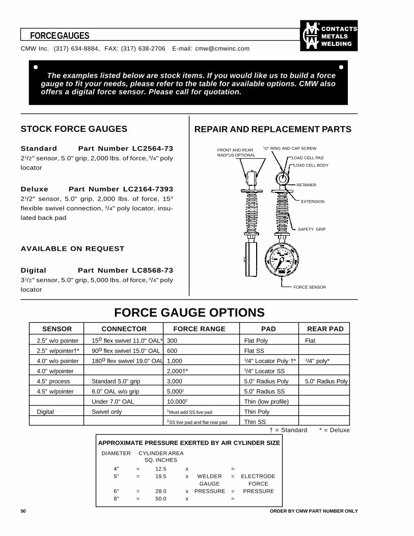
��������
�����
����
FORCE GAUGES
50 ORDER BY CMW PART NUMBER ONLY
The examples listed below are stock items. If you would like us to build a forcegauge to fit your needs, please refer to the table for available options. CMW alsooffers a digital force sensor. Please call for quotation.
REPAIR AND REPLACEMENT PARTSSTOCK FORCE GAUGES
Standard Part Number LC2564-7321/2" sensor, 5.0" grip, 2,000 lbs. of force, 3/4" poly
locator
Deluxe Part Number LC2164-739321/2" sensor, 5.0" grip, 2,000 lbs. of force, 15o
flexible swivel connection, 3/4" poly locator, insu-
lated back pad
AVAILABLE ON REQUEST
Digital Part Number LC8568-7331/2" sensor, 5.0" grip, 5,000 lbs. of force, 3/4" poly
locator
FORCE GAUGE OPTIONSSENSOR CONNECTOR FORCE RANGE PAD REAR PAD
2.5" w/o pointer 15o flex swivel 11.0" OAL* 300 Flat Poly Flat
2.5" w/pointer†* 90o flex swivel 15.0" OAL 600 Flat SS
4.0" w/o pointer 180o flex swivel 19.0" OAL 1,000 3/4" Locator Poly †* 3/4" poly*
4.0" w/pointer 2,000†* 3/4" Locator SS
4.5" process Standard 5.0" grip 3,000 5.0" Radius Poly 5.0" Radius Poly
4.5" w/pointer 6.0" OAL w/o grip 5,0001 5.0" Radius SS
Under 7.0" OAL 10,0002 Thin (low profile)
Digital Swivel only 1Must add SS live pad Thin Poly2SS live pad and flat rear pad Thin SS
† = Standard * = Deluxe
APPROXIMATE PRESSURE EXERTED BY AIR CYLINDER SIZE
DIAMETER CYLINDER AREASQ. INCHES
4" = 12.5 x =5" = 19.5 x WELDER = ELECTRODE
GAUGE FORCE6" = 28.0 x PRESSURE = PRESSURE8" = 50.0 x =
CMW Inc. (317) 634-8884, FAX: (317) 638-2706 E-mail: [email protected]
FRONT AND REARRADI"US OPTIONAL
"O" RING AND CAP SCREW
LOAD CELL PAD
LOAD CELL BODY
RETAINER
SAFETY GRIP
EXTENSION
FORCE SENSOR
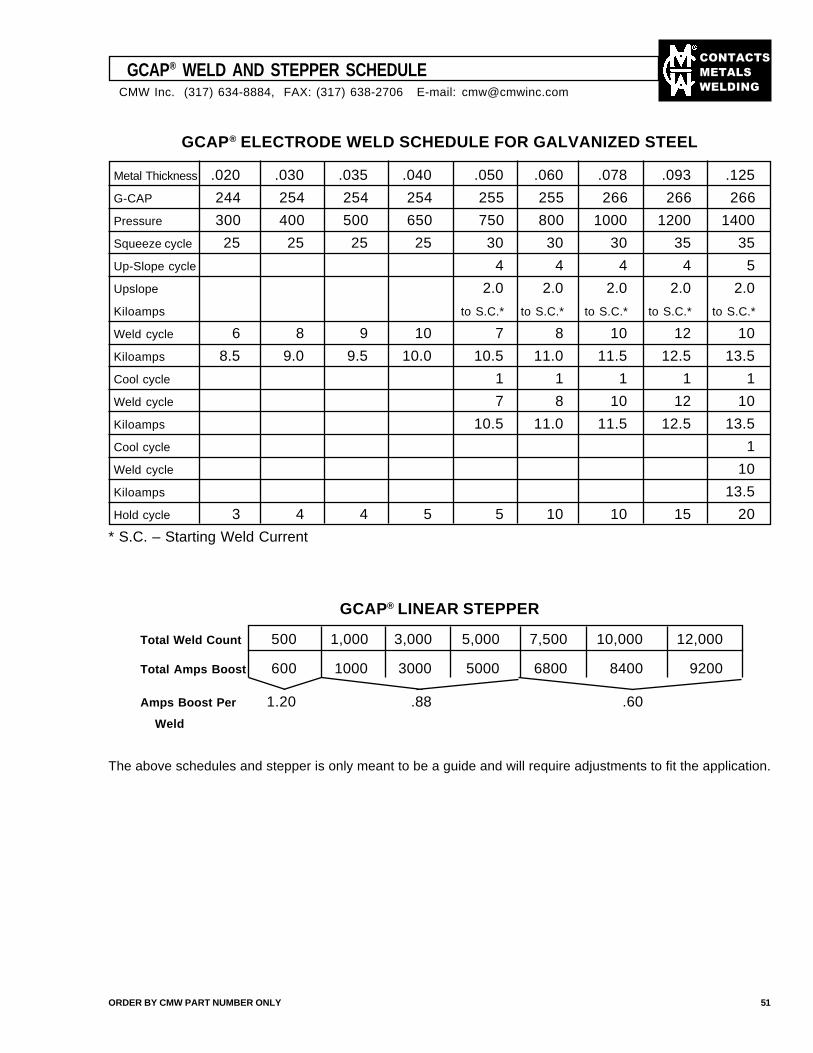
��������
�����
����
Total Weld Count 500 1,000 3,000 5,000 7,500 10,000 12,000
Total Amps Boost 600 1000 3000 5000 6800 8400 9200
Amps Boost Per 1.20 .88 .60
Weld
The above schedules and stepper is only meant to be a guide and will require adjustments to fit the application.
GCAP® WELD AND STEPPER SCHEDULE
ORDER BY CMW PART NUMBER ONLY 51
GCAP® LINEAR STEPPER
Metal Thickness .020 .030 .035 .040 .050 .060 .078 .093 .125
G-CAP 244 254 254 254 255 255 266 266 266
Pressure 300 400 500 650 750 800 1000 1200 1400
Squeeze cycle 25 25 25 25 30 30 30 35 35
Up-Slope cycle 4 4 4 4 5
Upslope 2.0 2.0 2.0 2.0 2.0
Kiloamps to S.C.* to S.C.* to S.C.* to S.C.* to S.C.*
Weld cycle 6 8 9 10 7 8 10 12 10
Kiloamps 8.5 9.0 9.5 10.0 10.5 11.0 11.5 12.5 13.5
Cool cycle 1 1 1 1 1
Weld cycle 7 8 10 12 10
Kiloamps 10.5 11.0 11.5 12.5 13.5
Cool cycle 1
Weld cycle 10
Kiloamps 13.5
Hold cycle 3 4 4 5 5 10 10 15 20
* S.C. – Starting Weld Current
GCAP® ELECTRODE WELD SCHEDULE FOR GALVANIZED STEEL
CMW Inc. (317) 634-8884, FAX: (317) 638-2706 E-mail: [email protected]
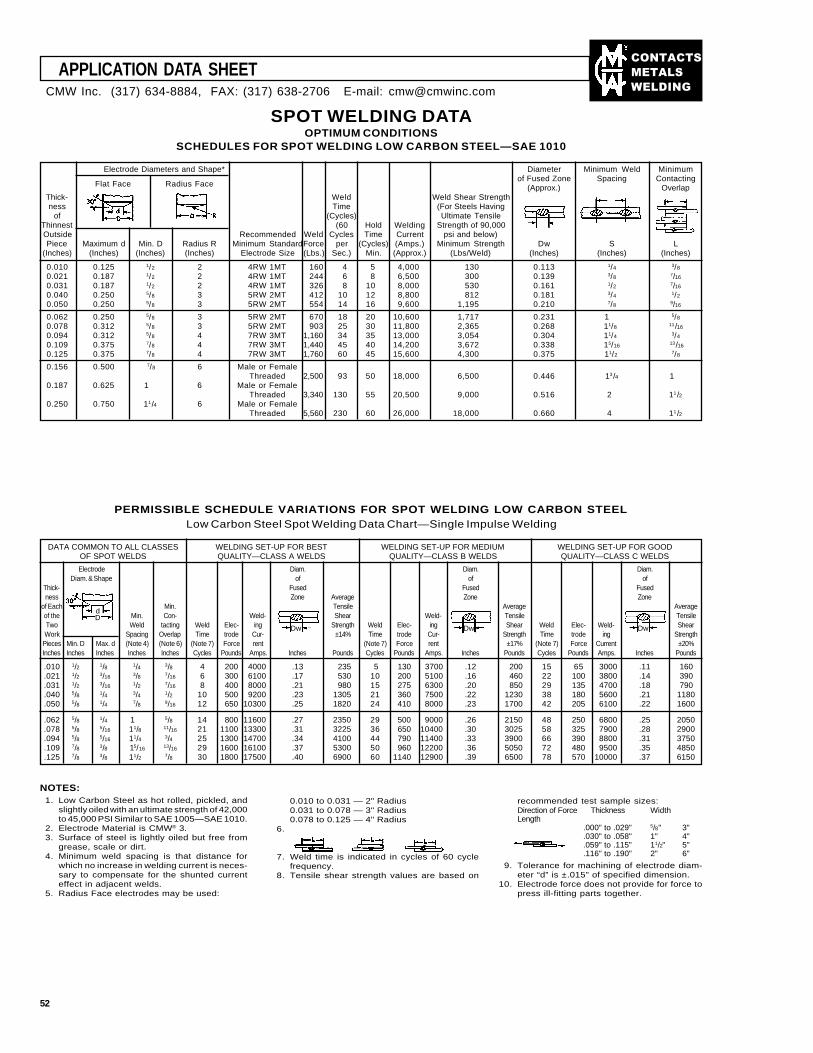
��������
�����
����
APPLICATION DATA SHEET
52
PERMISSIBLE SCHEDULE VARIATIONS FOR SPOT WELDING LOW CARBON STEELLow Carbon Steel Spot Welding Data Chart—Single Impulse Welding
DATA COMMON TO ALL CLASSES WELDING SET-UP FOR BEST WELDING SET-UP FOR MEDIUM WELDING SET-UP FOR GOODOF SPOT WELDS QUALITY—CLASS A WELDS QUALITY—CLASS B WELDS QUALITY—CLASS C WELDS
Electrode Diam. Diam. Diam.Diam. & Shape of of of
Thick- Fused Fused Fusedness Zone Average Zone Zone
of Each Min. Tensile Average Averageof the Min. Con- Weld- Shear Weld- Tensile TensileTwo Weld tacting Weld Elec- ing Strength Weld Elec- ing Shear Weld Elec- Weld- ShearWork Spacing Overlap Time trode Cur- ±14% Time trode Cur- Strength Time trode ing Strength
Pieces Min. D Max. d (Note 4) (Note 6) (Note 7) Force rent (Note 7) Force rent ±17% (Note 7) Force Current ±20%Inches Inches Inches Inches Inches Cycles Pounds Amps. Inches Pounds Cycles Pounds Amps. Inches Pounds Cycles Pounds Amps. Inches Pounds
.010 1/2 1/8 1/4 3/8 4 200 4000 .13 235 5 130 3700 .12 200 15 65 3000 .11 160
.021 1/2 3/16 3/8 7/16 6 300 6100 .17 530 10 200 5100 .16 460 22 100 3800 .14 390
.031 1/2 3/16 1/2 7/16 8 400 8000 .21 980 15 275 6300 .20 850 29 135 4700 .18 790
.040 5/8 1/4 3/4 1/2 10 500 9200 .23 1305 21 360 7500 .22 1230 38 180 5600 .21 1180
.050 5/8 1/4 7/8 9/16 12 650 10300 .25 1820 24 410 8000 .23 1700 42 205 6100 .22 1600
.062 5/8 1/4 1 5/8 14 800 11600 .27 2350 29 500 9000 .26 2150 48 250 6800 .25 2050
.078 5/8 5/16 11/8 11/16 21 1100 13300 .31 3225 36 650 10400 .30 3025 58 325 7900 .28 2900
.094 5/8 5/16 11/4 3/4 25 1300 14700 .34 4100 44 790 11400 .33 3900 66 390 8800 .31 3750
.109 7/8 3/8 15/16 13/16 29 1600 16100 .37 5300 50 960 12200 .36 5050 72 480 9500 .35 4850
.125 7/8 3/8 11/2 7/8 30 1800 17500 .40 6900 60 1140 12900 .39 6500 78 570 10000 .37 6150
Dd
Dw DwDw
NOTES:1. Low Carbon Steel as hot rolled, pickled, and
slightly oiled with an ultimate strength of 42,000to 45,000 PSI Similar to SAE 1005—SAE 1010.
2. Electrode Material is CMW® 3.3. Surface of steel is lightly oiled but free from
grease, scale or dirt.4. Minimum weld spacing is that distance for
which no increase in welding current is neces-sary to compensate for the shunted currenteffect in adjacent welds.
5. Radius Face electrodes may be used:
0.010 to 0.031 — 2" Radius0.031 to 0.078 — 3" Radius0.078 to 0.125 — 4" Radius
6.
7. Weld time is indicated in cycles of 60 cyclefrequency.
8. Tensile shear strength values are based on
recommended test sample sizes:Direction of Force Thickness WidthLength
.000" to .029" 5/8" 3"
.030" to .058" 1" 4"
.059" to .115" 11/2" 5"
.116" to .190" 2" 6"
9. Tolerance for machining of electrode diam-eter “d” is ±.015" of specified dimension.
10. Electrode force does not provide for force topress ill-fitting parts together.
SPOT WELDING DATAOPTIMUM CONDITIONS
SCHEDULES FOR SPOT WELDING LOW CARBON STEEL—SAE 1010
Electrode Diameters and Shape* Diameter Minimum Weld Minimumof Fused Zone Spacing Contacting
(Approx.) OverlapThick- Weld Weld Shear Strengthness Time (For Steels Having
of (Cycles) Ultimate TensileThinnest (60 Hold Welding Strength of 90,000Outside Recommended Weld Cycles Time Current psi and below)Piece Maximum d Min. D Radius R Minimum StandardForce per (Cycles) (Amps.) Minimum Strength Dw S L
(Inches) (Inches) (Inches) (Inches) Electrode Size (Lbs.) Sec.) Min. (Approx.) (Lbs/Weld) (Inches) (Inches) (Inches)
0.010 0.125 1/2 2 4RW 1MT 160 4 5 4,000 130 0.113 1/4 3/8
0.021 0.187 1/2 2 4RW 1MT 244 6 8 6,500 300 0.139 3/8 7/16
0.031 0.187 1/2 2 4RW 1MT 326 8 10 8,000 530 0.161 1/2 7/16
0.040 0.250 5/8 3 5RW 2MT 412 10 12 8,800 812 0.181 3/4 1/2
0.050 0.250 5/8 3 5RW 2MT 554 14 16 9,600 1,195 0.210 7/8 9/16
0.062 0.250 5/8 3 5RW 2MT 670 18 20 10,600 1,717 0.231 1 5/8
0.078 0.312 5/8 3 5RW 2MT 903 25 30 11,800 2,365 0.268 11/8 11/16
0.094 0.312 5/8 4 7RW 3MT 1,160 34 35 13,000 3,054 0.304 11/4 3/4
0.109 0.375 7/8 4 7RW 3MT 1,440 45 40 14,200 3,672 0.338 15/16 13/16
0.125 0.375 7/8 4 7RW 3MT 1,760 60 45 15,600 4,300 0.375 11/2 7/8
0.156 0.500 7/8 6 Male or FemaleThreaded 2,500 93 50 18,000 6,500 0.446 13/4 1
0.187 0.625 1 6 Male or FemaleThreaded 3,340 130 55 20,500 9,000 0.516 2 11/2
0.250 0.750 11/4 6 Male or FemaleThreaded 5,560 230 60 26,000 18,000 0.660 4 11/2
Flat Face Radius Face
CMW Inc. (317) 634-8884, FAX: (317) 638-2706 E-mail: [email protected]
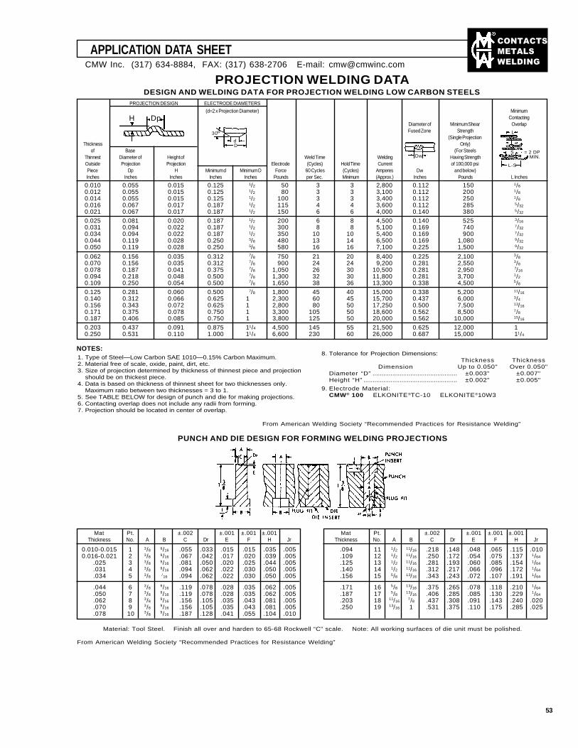
��������
�����
����
APPLICATION DATA SHEET
53
CMW Inc. (317) 634-8884, FAX: (317) 638-2706 E-mail: [email protected]
PROJECTION WELDING DATADESIGN AND WELDING DATA FOR PROJECTION WELDING LOW CARBON STEELS
(d=2 x Projection Diameter) MinimumContacting
Diameter of Minimum Shear OverlapFused Zone Strength
(Single ProjectionThickness Only)
of Base (For SteelsThinnest Diameter of Height of Weld Time Welding Having StrengthOutside Projection Projection Electrode (Cycles) Hold Time Current of 100,000 psiPiece Dp H Minimum d Minimum D Force 60 Cycles (Cycles) Amperes Dw and below)Inches Inches Inches Inches Inches Pounds per Sec. Minimum (Approx.) Inches Pounds L Inches
0.010 0.055 0.015 0.125 1/2 50 3 3 2,800 0.112 150 1/8
0.012 0.055 0.015 0.125 1/2 80 3 3 3,100 0.112 200 1/8
0.014 0.055 0.015 0.125 1/2 100 3 3 3,400 0.112 250 1/8
0.016 0.067 0.017 0.187 1/2 115 4 4 3,600 0.112 285 5/32
0.021 0.067 0.017 0.187 1/2 150 6 6 4,000 0.140 380 5/32
0.025 0.081 0.020 0.187 1/2 200 6 8 4,500 0.140 525 3/16
0.031 0.094 0.022 0.187 1/2 300 8 8 5,100 0.169 740 7/32
0.034 0.094 0.022 0.187 1/2 350 10 10 5,400 0.169 900 7/32
0.044 0.119 0.028 0.250 5/8 480 13 14 6,500 0.169 1,080 9/32
0.050 0.119 0.028 0.250 5/8 580 16 16 7,100 0.225 1,500 9/32
0.062 0.156 0.035 0.312 7/8 750 21 20 8,400 0.225 2,100 3/8
0.070 0.156 0.035 0.312 7/8 900 24 24 9,200 0.281 2,550 3/8
0.078 0.187 0.041 0.375 7/8 1,050 26 30 10,500 0.281 2,950 7/16
0.094 0.218 0.048 0.500 7/8 1,300 32 30 11,800 0.281 3,700 1/2
0.109 0.250 0.054 0.500 7/8 1,650 38 36 13,300 0.338 4,500 5/8
0.125 0.281 0.060 0.500 7/8 1,800 45 40 15,000 0.338 5,200 11/16
0.140 0.312 0.066 0.625 1 2,300 60 45 15,700 0.437 6,000 3/4
0.156 0.343 0.072 0.625 1 2,800 80 50 17,250 0.500 7,500 13/16
0.171 0.375 0.078 0.750 1 3,300 105 50 18,600 0.562 8,500 7/8
0.187 0.406 0.085 0.750 1 3,800 125 50 20,000 0.562 10,000 15/16
0.203 0.437 0.091 0.875 11/4 4,500 145 55 21,500 0.625 12,000 1 0.250 0.531 0.110 1.000 11/4 6,600 230 60 26,000 0.687 15,000 11/4
PROJECTION DESIGN ELECTRODE DIAMETERS
H Dp
30o
dD
Dw
L
S
L-S
= 2 DPMIN.
NOTES:1. Type of Steel—Low Carbon SAE 1010—0.15% Carbon Maximum.2. Material free of scale, oxide, paint, dirt, etc.3. Size of projection determined by thickness of thinnest piece and projection
should be on thickest piece.4. Data is based on thickness of thinnest sheet for two thicknesses only.
Maximum ratio between two thicknesses = 3 to 1.5. See TABLE BELOW for design of punch and die for making projections.6. Contacting overlap does not include any radii from forming.7. Projection should be located in center of overlap.
8. Tolerance for Projection Dimensions:Thickness Thickness
Dimension Up to 0.050" Over 0.050"Diameter “D” ............................................... ±0.003" ±0.007"Height “H” .................................................... ±0.002" ±0.005"
9. Electrode Material:CMW® 100 ELKONITE®TC-10 ELKONITE®10W3
PUNCH AND DIE DESIGN FOR FORMING WELDING PROJECTIONS
Mat Pt. ±.002 ±.001 ±.001 ±.001Thickness No. A B C Dr E F H Jr
0.010-0.015 1 3/8 9/16 .055 .033 .015 .015 .035 .0050.016-0.021 2 3/8 9/16 .067 .042 .017 .020 .039 .005
.025 3 3/8 9/16 .081 .050 .020 .025 .044 .005
.031 4 3/8 9/16 .094 .062 .022 .030 .050 .005
.034 5 3/8 /16 .094 .062 .022 .030 .050 .005
.044 6 3/89/16 .119 .078 .028 .035 .062 .005
.050 7 3/89/16 .119 .078 .028 .035 .062 .005
.062 8 3/89/16 .156 .105 .035 .043 .081 .005
.070 9 3/89/16 .156 .105 .035 .043 .081 .005
.078 10 3/89/16 .187 .128 .041 .055 .104 .010
Mat Pt. ±.002 ±.001 ±.001 ±.001Thickness No. A B C Dr E F H Jr
.094 11 1/2 11/16 .218 .148 .048 .065 .115 .010
.109 12 1/2 11/16 .250 .172 .054 .075 .137 1/64
.125 13 1/2 11/16 .281 .193 .060 .085 .154 1/64
.140 14 1/2 11/16 .312 .217 .066 .096 .172 1/64
.156 15 5/8 13/16 .343 .243 .072 .107 .191 1/64
.171 16 5/813/16 .375 .265 .078 .118 .210 1/64
.187 17 5/813/16 .406 .285 .085 .130 .229 1/64
.203 18 11/167/8 .437 .308 .091 .143 .240 .020
.250 19 13/16 1 .531 .375 .110 .175 .285 .025
Material: Tool Steel. Finish all over and harden to 65-68 Rockwell “C” scale. Note: All working surfaces of die unit must be polished.
From American Welding Society “Recommended Practices for Resistance Welding”
From American Welding Society “Recommended Practices for Resistance Welding”
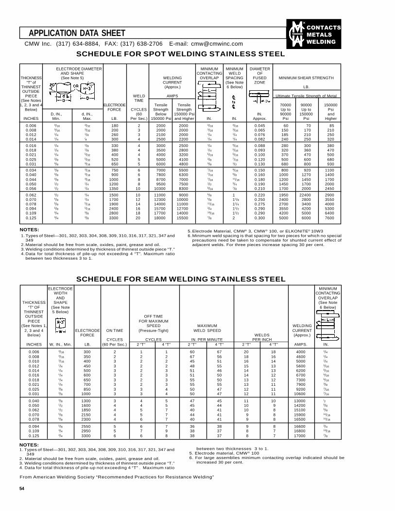
��������
�����
����
ELECTRODE DIAMETER MINIMUM MINIMUM DIAMETERAND SHAPE CONTACTING WELD OF
THICKNESS (See Note 5) WELDING OVERLAP SPACING FUSED MINIMUM SHEAR STRENGTH“T” of CURRENT (See Note ZONE
THINNEST (Approx.) 6 Below) LB.OUTSIDE
PIECE WELD AMPS Ultimate Tensile Strength of Metal(See Notes TIME
1, 2, 3 and 4 ELECTRODE Tensile Tensile 70000 90000 150000Below) FORCE CYCLES Strength Strength Up to Up to Psi
D, IN., d, IN., (60 Below 150000 Psi IN. 90000 150000 andINCHES Min. Max. LB. Per Sec.) 150000 Psi and Higher IN. IN. Approx. Psi Psi Higher
0.006 3/16 3/32 180 2 2000 2000 3/16 3/16 0.045 60 70 850.008 3/16 3/32 200 3 2000 2000 3/16 3/16 0.065 150 170 2100.012 1/4 1/8 260 3 2100 2000 1/4 1/4 0.076 185 210 2500.014 1/4 /8 300 4 2500 2200 1/4 1/4 0.082 240 250 320
0.016 1/4 1/8 330 4 3000 2500 1/4 5/16 0.088 280 300 3800.018 1/4 1/8 380 4 3500 2800 1/4 5/16 0.093 320 360 4700.021 1/4 5/32 400 4 4000 3200 5/16 5/16 0.100 370 470 5000.025 3/8 5/32 520 5 5000 4100 3/8 7/16 0.120 500 600 6800.031 3/8 3/16 650 5 6000 4800 3/8 1/2 0.130 680 800 930
0.034 3/8 3/16 750 6 7000 5500 7/16 9/16 0.150 800 920 11000.040 3/8 3/16 900 6 7800 6300 7/16 5/8 0.160 1000 1270 14000.044 3/8 3/16 1000 8 8700 7000 7/16 11/16 0.180 1200 1450 17000.050 1/2 1/4 1200 8 9500 7500 1/2 3/4 0.190 1450 1700 20000.056 1/2 1/4 1350 10 10300 8300 9/16 7/8 0.210 1700 2000 2450
0.062 1/2 1/4 1500 10 11000 9000 5/8 1 0.220 1950 22400 29000.070 5/8 1/4 1700 12 12300 10000 5/8 11/8 0.250 2400 2800 35500.078 5/8 5/16 1900 14 14000 11000 11/16 11/4 0.275 2700 3400 40000.094 5/8 5/16 2400 16 15700 12700 3/4 11/2 0.290 3550 4200 53000.109 3/4 3/8 2800 18 17700 14000 13/16 11/2 0.290 4200 5000 64000.125 3/4 3/8 3300 20 18000 15500 7/8 2 0.300 5000 6000 7600
SCHEDULE FOR SPOT WELDING STAINLESS STEEL
APPLICATION DATA SHEET
ELECTRODE MINIMUMWIDTH CONTACTING
AND OVERLAPTHICKNESS SHAPE (See Note
“T” OF (See Note 6 Below)THINNEST 5 Below)OUTSIDE OFF TIME
PIECE FOR MAXIMUM(See Notes 1, SPEED MAXIMUM WELDING
2, 3 and 4 ELECTRODE ON TIME (Pressure-Tight) WELD SPEED CURRENTBelow) FORCE WELDS (Approx.)
CYCLES CYCLES IN. PER MINUTE PER INCHINCHES W, IN., Min. LB. (60 Per Sec.) 2 “T” 4 “T” 2 “T” 4 “T” 2 “T” 4 “T” AMPS. IN.
0.006 3/16 300 2 1 1 60 67 20 18 4000 1/4
0.008 3/16 350 2 2 2 67 56 18 16 4600 1/4
0.010 3/16 400 3 2 2 45 51 16 14 5000 1/4
0.012 1/4 450 3 2 2 48 55 15 13 5600 5/16
0.014 1/4 500 3 2 3 51 46 14 13 6200 5/16
0.016 1/4 600 3 2 3 51 50 14 12 6700 5/16
0.018 1/4 650 3 2 3 55 50 13 12 7300 5/16
0.021 1/4 700 3 2 3 55 55 13 11 7900 3/8
0.025 3/8 850 3 3 4 50 47 12 11 9200 7/16
0.031 3/8 1000 3 3 4 50 47 12 11 10600 7/16
0.040 3/8 1300 3 4 5 47 45 11 10 13000 /2
0.050 1/2 1600 4 4 5 45 44 10 9 14200 5/8
0.062 1/2 1850 4 5 7 40 41 10 8 15100 5/8
0.070 5/8 2150 4 5 7 44 41 9 8 15900 11/16
0.078 5/8 2300 4 6 7 40 41 9 8 16500 11/16
0.094 5/8 2550 5 6 7 36 38 9 8 16600 3/4
0.109 3/4 2950 5 7 9 38 37 8 7 16800 13/16
0.125 3/4 3300 6 6 8 38 37 8 7 17000 7/8
SCHEDULE FOR SEAM WELDING STAINLESS STEEL
NOTES:1. Types of Steel—301, 302, 303, 304, 308, 309, 310, 316, 317, 321, 347 and
3492. Material should be free from scale, oxides, paint, grease and oil.3. Welding conditions determined by thickness of thinnest outside piece “T.”4. Data for total thickness of pile-up not exceeding 4 “T”. Maximum ratio
between two thicknesses 3 to 1.
5. Electrode Material, CMW® 3, CMW® 100, or ELKONITE® 10W36. Minimum weld spacing is that spacing for two pieces for which no special
precautions need be taken to compensate for shunted current effect ofadjacent welds. For three pieces increase spacing 30 per cent.
NOTES:1. Types of Steel—301, 302, 303, 304, 308, 309, 310, 316, 317, 321, 347 and
3492. Material should be free from scale, oxides, paint, grease and oil.3. Welding conditions determined by thickness of thinnest outside piece “T.”4. Data for total thickness of pile-up not exceeding 4 “T” . Maximum ratio
between two thicknesses 3 to 1.5. Electrode material, CMW® 1006. For large assemblies minimum contacting overlap indicated should be
increased 30 per cent.
From American Welding Society “Recommended Practices for Resistance Welding”
CMW Inc. (317) 634-8884, FAX: (317) 638-2706 E-mail: [email protected]
54
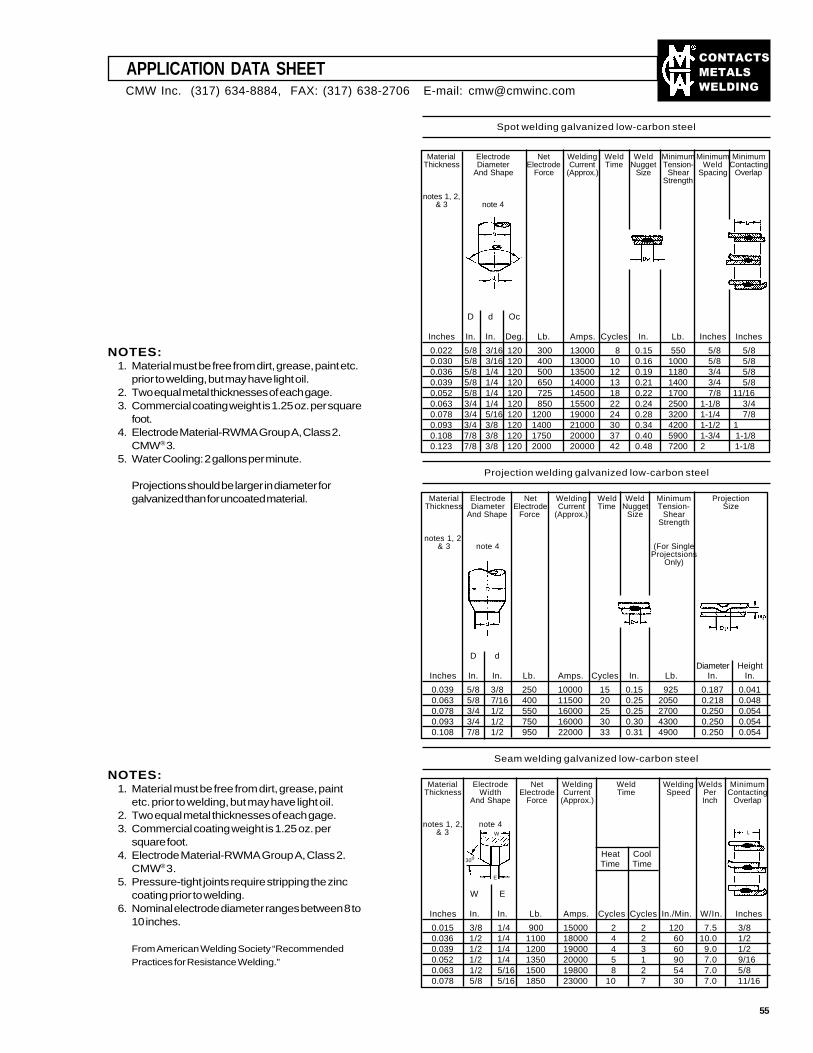
��������
�����
����
APPLICATION DATA SHEET
NOTES:1. Material must be free from dirt, grease, paint etc.
prior to welding, but may have light oil.2. Two equal metal thicknesses of each gage.3. Commercial coating weight is 1.25 oz. per square
foot.4. Electrode Material-RWMA Group A, Class 2.
CMW® 3.5. Water Cooling: 2 gallons per minute.
Projections should be larger in diameter forgalvanized than for uncoated material.
Material Electrode Net Welding Weld Weld Minimum Minimum MinimumThickness Diameter Electrode Current Time Nugget Tension- Weld Contacting
And Shape Force (Approx.) Size Shear Spacing OverlapStrength
notes 1, 2,& 3 note 4
D d Oc
Inches In. In. Deg. Lb. Amps. Cycles In. Lb. Inches Inches
0.022 5/8 3/16 120 300 13000 8 0.15 550 5/8 5/80.030 5/8 3/16 120 400 13000 10 0.16 1000 5/8 5/80.036 5/8 1/4 120 500 13500 12 0.19 1180 3/4 5/80.039 5/8 1/4 120 650 14000 13 0.21 1400 3/4 5/80.052 5/8 1/4 120 725 14500 18 0.22 1700 7/8 11/160.063 3/4 1/4 120 850 15500 22 0.24 2500 1-1/8 3/40.078 3/4 5/16 120 1200 19000 24 0.28 3200 1-1/4 7/80.093 3/4 3/8 120 1400 21000 30 0.34 4200 1-1/2 1 0.108 7/8 3/8 120 1750 20000 37 0.40 5900 1-3/4 1-1/80.123 7/8 3/8 120 2000 20000 42 0.48 7200 2 1-1/8
Projection welding galvanized low-carbon steel
Material Electrode Net Welding Weld Weld Minimum ProjectionThickness Diameter Electrode Current Time Nugget Tension- Size
And Shape Force (Approx.) Size ShearStrength
notes 1, 2,& 3 note 4 (For Single
ProjectsionsOnly)
D dDiameter Height
Inches In. In. Lb. Amps. Cycles In. Lb. In. In.
0.039 5/8 3/8 250 10000 15 0.15 925 0.187 0.0410.063 5/8 7/16 400 11500 20 0.25 2050 0.218 0.0480.078 3/4 1/2 550 16000 25 0.25 2700 0.250 0.0540.093 3/4 1/2 750 16000 30 0.30 4300 0.250 0.0540.108 7/8 1/2 950 22000 33 0.31 4900 0.250 0.054
Seam welding galvanized low-carbon steel
Material Electrode Net Welding Weld Welding Welds MinimumThickness Width Electrode Current Time Speed Per Contacting
And Shape Force (Approx.) Inch Overlap
notes 1, 2, note 4& 3
Heat CoolTime Time
W E
Inches In. In. Lb. Amps. Cycles Cycles In./Min. W/In. Inches
0.015 3/8 1/4 900 15000 2 2 120 7.5 3/80.036 1/2 1/4 1100 18000 4 2 60 10.0 1/20.039 1/2 1/4 1200 19000 4 3 60 9.0 1/20.052 1/2 1/4 1350 20000 5 1 90 7.0 9/160.063 1/2 5/16 1500 19800 8 2 54 7.0 5/80.078 5/8 5/16 1850 23000 10 7 30 7.0 11/16
Spot welding galvanized low-carbon steel
W
30o
E
L
NOTES:1. Material must be free from dirt, grease, paint
etc. prior to welding, but may have light oil.2. Two equal metal thicknesses of each gage.3. Commercial coating weight is 1.25 oz. per
square foot.4. Electrode Material-RWMA Group A, Class 2.
CMW® 3.5. Pressure-tight joints require stripping the zinc
coating prior to welding.6. Nominal electrode diameter ranges between 8 to
10 inches.
From American Welding Society “RecommendedPractices for Resistance Welding.”
CMW Inc. (317) 634-8884, FAX: (317) 638-2706 E-mail: [email protected]
55
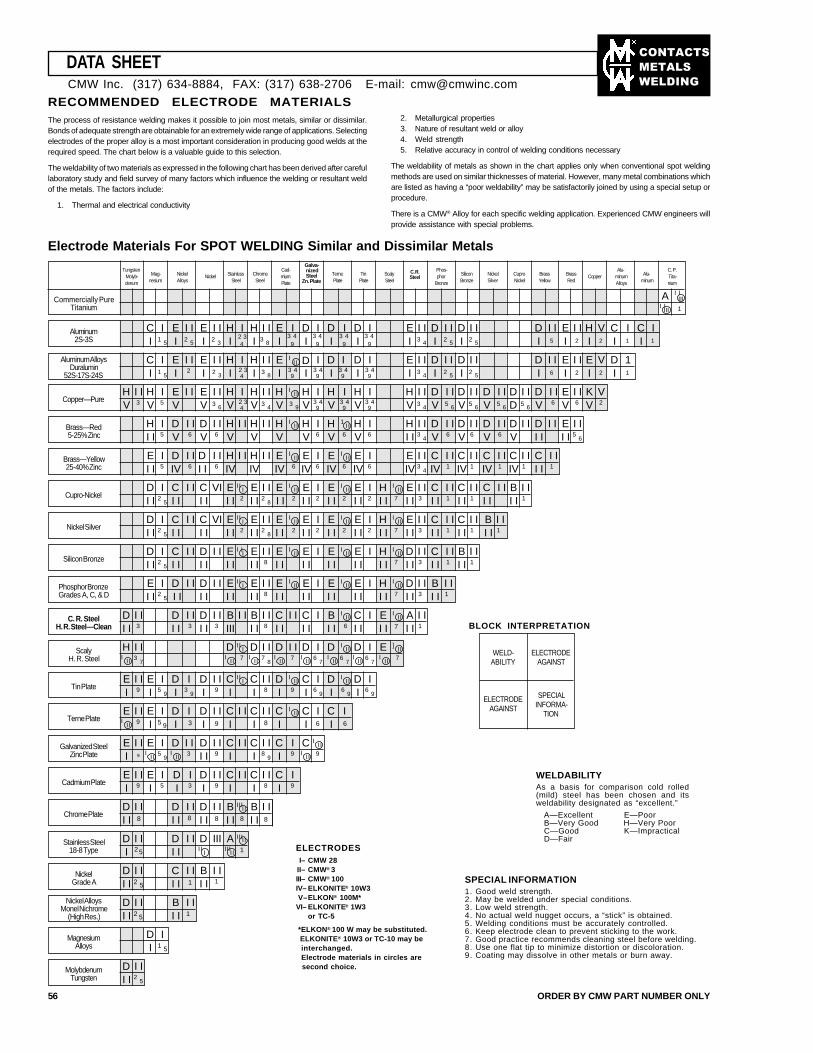
��������
�����
����
II
I
TungstenMolyb-denum
Mag-nesium
NickelAlloys
Nickel StainlessSteel
ChromeSteel
Cad-miumPlate
Galva-nizedSteel
Zn. PlateTernePlate
TinPlate
ScalySteel
C. R.Steel
Phos-phor
Bronze
SiliconBronze
NickelSilver
CuproNickel
BrassYellow
BrassRed
CopperAlu-
minumAlloys
Alu-minum
C. P.Tita-nium
Commercially PureTitanium
A
Aluminum2S-3S
Aluminum AlloysDuralumin
52S-17S-24S
Copper—Pure
Brass—Red5-25% Zinc
Brass—Yellow25-40% Zinc
Cupro-Nickel
Nickel Silver
Silicon Bronze
Phosphor BronzeGrades A, C, & D
C. R. SteelH. R. Steel—Clean
ScalyH. R. Steel
Tin Plate
Terne Plate
Galvanized SteelZinc Plate
Cadmium Plate
Chrome Plate
Stainless Steel18-8 Type
NickelGrade A
Nickel AlloysMonel Nichrome
(High Res.)
MagnesiumAlloys
C II 1 5
EI
I I2 5
EI
I I2 3
HI
I4
HI
I I3 8
EI
I9
I9
DI
DI
I9
IDI
EI
I I3 4
DI
I I2 5
DI
I I I IDI 5
EI
I I2
HI
V2
CI 1
I CI
I1
C II
EI
I I2
EI
I I HI
I4
HI
I I EI
II IDI
IDI
IDI
EI
I I DI
I I DI
I I I IDI 6
EI
I I2
EI
V2
1
DI 1
1
DI
I1 5
DI I
I I2 5
BI I
I I
HV
I I3
HV
I5
EV
I I EV
I I HV
I HV
I I IHV
II IHV
HV
I HV
I HV
I I DV
I I DV
I I DV
I I DD
I I DV
I I6
EV
I I6
KV
V2
HI I
I5
DV
I I6
DV
I I6
HV
I I HV
I I IHV
II HV
I6
1H II
V 6
HV
I6
HI I
I I3
4
DV 6
DV
I I I I6
DV
I I6
DV
I I DI I
I I EI I
I I5
6
EI I
I5
DIV
I I6
DI I
I I6
HIV
I I HIV
I I IEIV
II6
EIV
I6
IE II
IV 6
EIV
I6
EIV
I I3
4
CIV 1
I I CIV
I I1
CIV
I I1
CIV
I I1
CI I
I I1
DI I
I2
5
CI I
I I CI I
VI EI I
I2
EI I
I I2
8
IE I I
II2
EI I
I2
IE II
I I 2
EI I
I2
IH II
I I 7
EI I
I I3
CI I 1
I I CI I 1
I I CI I
I I BI I
I I1
DI I
I2
5
CI I
I I CI I
VI IIEI I
I2
EI I
I I2
8
IEI I
II2
EI I
I2
IE II
I I 2
EI I
I2
IH II
I I 7
EI I
I I3
CI I 1
I I CI I 1
I I BI I
I I1
DI I
I2
5
CI I
I I DI I
I I I IEI I
I EI I
I I8
IEI I
II EI I
I IE II
I IEI I
I IH II
I I 7
DI I
I I3
CI I 1
I I BI I
I I1
EI I
I2
5
D I I DI I
I I IIEI I
I EI I
I I8
IEI I
II EI I
I IE II
I IEI I
I IH II
I I 7
DI I
I I3
I I1
BI I
DI I
I I3
DI I
I I3
I I3
BIII
I I BI I
I I8
I ICI I
CI I
I IB II
I IDI I 6
CI I
I IE II
I I 7
AI I
I I1
H I I3
7
IID I7
D I I7
8
D I I7
D I6
7
ID II6
7
D I6
7
]E II7
EI
I I9
E I5
9ID II 3
9
DI
I I9
IIC I
ICI
I I8
ID II
I 9
CI
I6
9
ID II
I 6 9
DI
I6
9
E I I9
E I5 9I
DI
I3
DI
I I9
CI
I I CI
I I8
IC II
ICI
I6
CI
I
EI
I I9
E I5
9
D I I3
DI I
I I9
CI
I I C I I8
9ICI
I9
C III
9
EI
I I9
EI
I5
DI
I3
DI
I I9
CI
I I CI
I I8
CI
I9
DI I
I I DI I
I I8
DI I
I I8
IIIB II
I I 8
BI I
I I8
D I II
DI I
I I D III IIIA1
DI I
I I2 5
CI I
I I1
BI I
I I1
Electrode Materials For SPOT WELDING Similar and Dissimilar Metals
III
III
III
III
IIIII
III
III
III
III
III
III
III
III
III
I IMolybdenumTungsten
DI I 2
5
RECOMMENDED ELECTRODE MATERIALSThe process of resistance welding makes it possible to join most metals, similar or dissimilar.Bonds of adequate strength are obtainable for an extremely wide range of applications. Selectingelectrodes of the proper alloy is a most important consideration in producing good welds at therequired speed. The chart below is a valuable guide to this selection.
The weldability of two materials as expressed in the following chart has been derived after carefullaboratory study and field survey of many factors which influence the welding or resultant weldof the metals. The factors include:
1. Thermal and electrical conductivity
2. Metallurgical properties3. Nature of resultant weld or alloy4. Weld strength5. Relative accuracy in control of welding conditions necessary
The weldability of metals as shown in the chart applies only when conventional spot weldingmethods are used on similar thicknesses of material. However, many metal combinations whichare listed as having a “poor weldability” may be satisfactorily joined by using a special setup orprocedure.
There is a CMW® Alloy for each specific welding application. Experienced CMW engineers willprovide assistance with special problems.
DATA SHEET
56 ORDER BY CMW PART NUMBER ONLY
I I
IIII I
III
CMW Inc. (317) 634-8884, FAX: (317) 638-2706 E-mail: [email protected]
II
2 5
1
8
6
92 5
3 43 4 3 43 4 2 3
1 5 2 3 3 8 9 9 9 93 4 2 5 2 5
3 4 3 4 3 4 3 4 2 3
3 6 43 4 3 9 9 9 9
3 4 5 6 5 6 5 6 5 6 2 3 3 4 3 4 3 4
I I
BLOCK INTERPRETATION
WELD-ABILITY
ELECTRODEAGAINST
ELECTRODEAGAINST
SPECIALINFORMA-
TION
WELDABILITYAs a basis for comparison cold rolled(mild) steel has been chosen and itsweldability designated as “excellent.”
A—Excellent E—PoorB—Very Good H—Very PoorC—Good K—ImpracticalD—Fair
ELECTRODESI– CMW 28
II– CMW® 3III– CMW® 100IV– ELKONITE® 10W3 V–ELKON® 100M*VI– ELKONITE® 1W3
or TC-5
*ELKON® 100 W may be substituted. ELKONITE® 10W3 or TC-10 may be
interchanged.Electrode materials in circles are
second choice.
SPECIAL INFORMATION1. Good weld strength.2. May be welded under special conditions.3. Low weld strength.4. No actual weld nugget occurs, a “stick” is obtained.5. Welding conditions must be accurately controlled.6. Keep electrode clean to prevent sticking to the work.7. Good practice recommends cleaning steel before welding.8. Use one flat tip to minimize distortion or discoloration.9. Coating may dissolve in other metals or burn away.
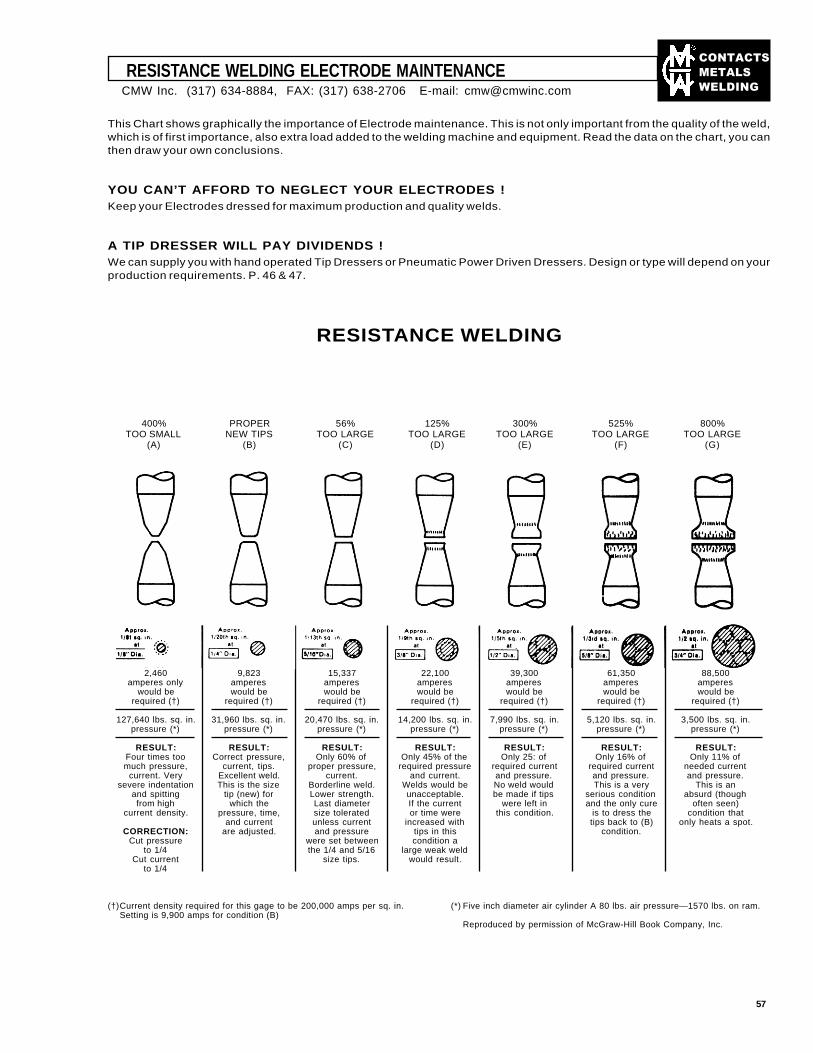
��������
�����
����
RESISTANCE WELDING ELECTRODE MAINTENANCE
This Chart shows graphically the importance of Electrode maintenance. This is not only important from the quality of the weld,which is of first importance, also extra load added to the welding machine and equipment. Read the data on the chart, you canthen draw your own conclusions.
YOU CAN’T AFFORD TO NEGLECT YOUR ELECTRODES !Keep your Electrodes dressed for maximum production and quality welds.
A TIP DRESSER WILL PAY DIVIDENDS !We can supply you with hand operated Tip Dressers or Pneumatic Power Driven Dressers. Design or type will depend on yourproduction requirements. P. 46 & 47.
400%TOO SMALL
(A)
PROPERNEW TIPS
(B)
56%TOO LARGE
(C)
125%TOO LARGE
(D)
300%TOO LARGE
(E)
525%TOO LARGE
(F)
800%TOO LARGE
(G)
RESISTANCE WELDING
2,460 9,823 15,337 22,100 39,300 61,350 88,500amperes only amperes amperes amperes amperes amperes amperes
would be would be would be would be would be would be would berequired (†) required (†) required (†) required (†) required (†) required (†) required (†)
127,640 lbs. sq. in. 31,960 lbs. sq. in. 20,470 lbs. sq. in. 14,200 lbs. sq. in. 7,990 lbs. sq. in. 5,120 lbs. sq. in. 3,500 lbs. sq. in.pressure (*) pressure (*) pressure (*) pressure (*) pressure (*) pressure (*) pressure (*)
RESULT: RESULT: RESULT: RESULT: RESULT: RESULT: RESULT:Four times too Correct pressure, Only 60% of Only 45% of the Only 25: of Only 16% of Only 11% ofmuch pressure, current, tips. proper pressure, required pressure required current required current needed current
current. Very Excellent weld. current. and current. and pressure. and pressure. and pressure.severe indentation This is the size Borderline weld. Welds would be No weld would This is a very This is an
and spitting tip (new) for Lower strength. unacceptable. be made if tips serious condition absurd (thoughfrom high which the Last diameter If the current were left in and the only cure often seen)
current density. pressure, time, size tolerated or time were this condition. is to dress the condition thatand current unless current increased with tips back to (B) only heats a spot.
CORRECTION: are adjusted. and pressure tips in this condition.Cut pressure were set between condition a
to 1/4 the 1/4 and 5/16 large weak weldCut current size tips. would result.
to 1/4
(†)Current density required for this gage to be 200,000 amps per sq. in.Setting is 9,900 amps for condition (B)
(*) Five inch diameter air cylinder A 80 lbs. air pressure—1570 lbs. on ram.
Reproduced by permission of McGraw-Hill Book Company, Inc.
CMW Inc. (317) 634-8884, FAX: (317) 638-2706 E-mail: [email protected]
57
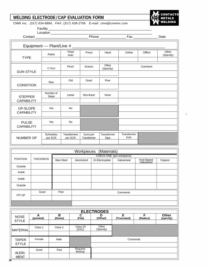
��������
�����
����
WELDING ELECTRODE / CAP EVALUATION FORMCMW Inc. (317) 634-8884, FAX: (317) 638-2706 E-mail: [email protected]
Facility _______________________________________________________Location ______________________________________________________
Contact ____________________________ Phone ______________ Fax _____________ Date_______________
Equipment --- Plant/Line # _________________________________________
TYPERobot
FixedAuto
Press Hand Online Offline Other(Specify)
GUN STYLEC Gun
Pinch Scissor Other(Specify)
Comment
CONDITIONNew
Old Good Poor
UP-SLOPECAPABILITY
STEPPERCAPABILITY
Number ofSteps Linear Non-linear None
Yes No
PULSECAPABILITY
Yes No
NUMBER OFSchedulesper SCR
Transformersper SCR
Guns perTransformer
TransformerTaps
TransformerKVA
123456789012345678901234567890121231234567890123456789012345678901212312345678901234567890123456789012123123456789012345678901234567890121231234567890123456789012345678901212312345678901234567890123456789012123123456789012345678901234567890121231234567890123456789012345678901212312345678901234567890123456789012123123456789012345678901234567890121231234567890123456789012345678901212312345678901234567890123456789012123123456789012345678901234567890121231234567890123456789012345678901212312345678901234567890123456789012123123456789012345678901234567890121231234567890123456789012345678901212312345678901234567890123456789012123123456789012345678901234567890121231234567890123456789012345678901212312345678901234567890123456789012123123456789012345678901234567890121231234567890123456789012345678901212312345678901234567890123456789012123
123456789012345678901234567890121234123456789012345678901234567890121234123456789012345678901234567890121234123456789012345678901234567890121234123456789012345678901234567890121234123456789012345678901234567890121234123456789012345678901234567890121234123456789012345678901234567890121234123456789012345678901234567890121234123456789012345678901234567890121234123456789012345678901234567890121234123456789012345678901234567890121234
Workpieces (Materials)CHECK ONE (per workpiece)
Bare Steel Aluminized Zn Electroplate Galvanneal OrganicHod DippedGalvanized
POSITION THICKNESS
Outside
Inside
Inside
Outside
123456789012345678901234567890121234567890123456789011234567890123456789012345678901212345678901234567890112345678901234567890123456789012123456789012345678901123456789012345678901234567890121234567890123456789011234567890123456789012345678901212345678901234567890112345678901234567890123456789012123456789012345678901
FIT-UPGood Poor Comments
ELECTRODESNOSESTYLE
A(pointed)
B(Dome)
C(Flat)
D(Offset)
E(Truncated)
F(Radius)
Other(specify)
MATERIALClass 1 Class 2 Class 20
(DSC)Other
(Specify)
123456789012345678901234567890121234567890123456789012345671234567890123456789012345678901212345678901234567890123456712345678901234567890123456789012123456789012345678901234567123456789012345678901234567890121234567890123456789012345671234567890123456789012345678901212345678901234567890123456712345678901234567890123456789012123456789012345678901234567123456789012345678901234567890121234567890123456789012345671234567890123456789012345678901212345678901234567890123456712345678901234567890123456789012123456789012345678901234567123456789012345678901234567890121234567890123456789012345671234567890123456789012345678901212345678901234567890123456712345678901234567890123456789012123456789012345678901234567
TAPERSTYLE
Female Male
12345678901234567890123456789012345678901234567890123456789012345678901234567890123456789012345678901234567890123456789012345678901234567890123456789012345678901234567890123456789012345678901234567890
ALIGN-MENT
Good Poor RequiresBackup
Comments
58
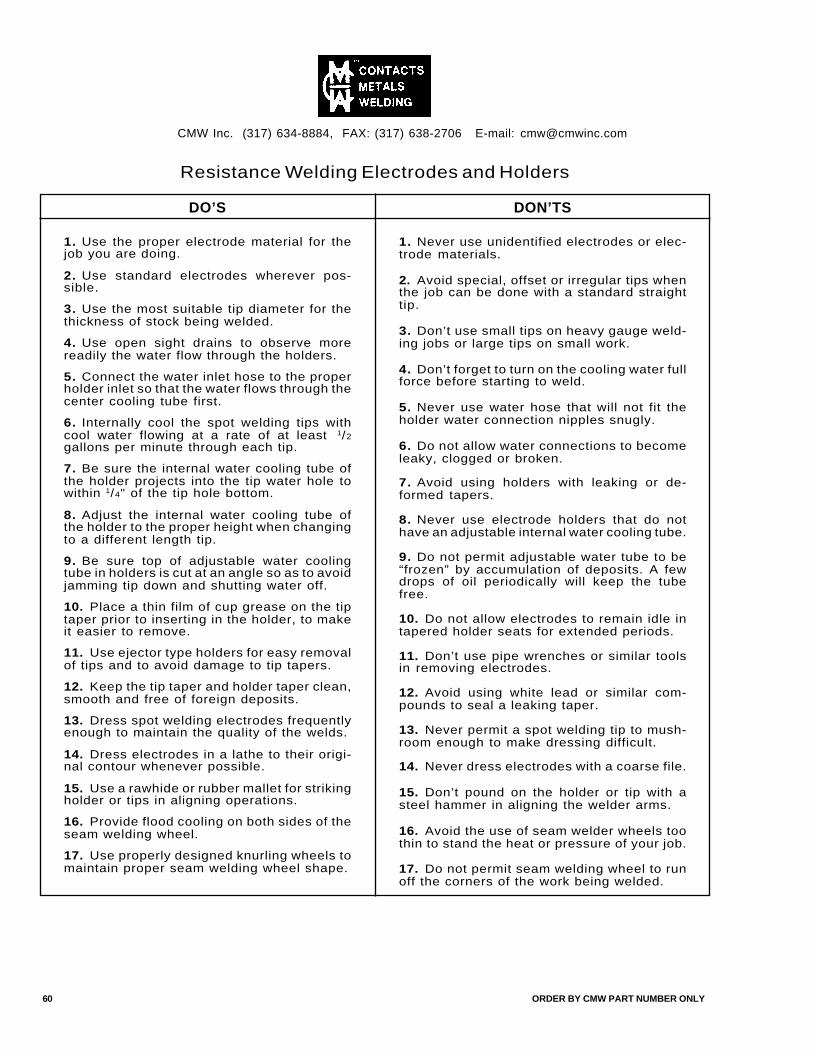
Resistance Welding Electrodes and Holders
DO’S DON’TS
1. Use the proper electrode material for thejob you are doing.
2. Use standard electrodes wherever pos-sible.
3. Use the most suitable tip diameter for thethickness of stock being welded.
4. Use open sight drains to observe morereadily the water flow through the holders.
5. Connect the water inlet hose to the properholder inlet so that the water flows through thecenter cooling tube first.
6. Internally cool the spot welding tips withcool water flowing at a rate of at least 1/2
gallons per minute through each tip.
7. Be sure the internal water cooling tube ofthe holder projects into the tip water hole towithin 1/4" of the tip hole bottom.
8. Adjust the internal water cooling tube ofthe holder to the proper height when changingto a different length tip.
9. Be sure top of adjustable water coolingtube in holders is cut at an angle so as to avoidjamming tip down and shutting water off.
10. Place a thin film of cup grease on the tiptaper prior to inserting in the holder, to makeit easier to remove.
11. Use ejector type holders for easy removalof tips and to avoid damage to tip tapers.
12. Keep the tip taper and holder taper clean,smooth and free of foreign deposits.
13. Dress spot welding electrodes frequentlyenough to maintain the quality of the welds.
14. Dress electrodes in a lathe to their origi-nal contour whenever possible.
15. Use a rawhide or rubber mallet for strikingholder or tips in aligning operations.
16. Provide flood cooling on both sides of theseam welding wheel.
17. Use properly designed knurling wheels tomaintain proper seam welding wheel shape.
1. Never use unidentified electrodes or elec-trode materials.
2. Avoid special, offset or irregular tips whenthe job can be done with a standard straighttip.
3. Don’t use small tips on heavy gauge weld-ing jobs or large tips on small work.
4. Don’t forget to turn on the cooling water fullforce before starting to weld.
5. Never use water hose that will not fit theholder water connection nipples snugly.
6. Do not allow water connections to becomeleaky, clogged or broken.
7. Avoid using holders with leaking or de-formed tapers.
8. Never use electrode holders that do nothave an adjustable internal water cooling tube.
9. Do not permit adjustable water tube to be“frozen” by accumulation of deposits. A fewdrops of oil periodically will keep the tubefree.
10. Do not allow electrodes to remain idle intapered holder seats for extended periods.
11. Don’t use pipe wrenches or similar toolsin removing electrodes.
12. Avoid using white lead or similar com-pounds to seal a leaking taper.
13. Never permit a spot welding tip to mush-room enough to make dressing difficult.
14. Never dress electrodes with a coarse file.
15. Don’t pound on the holder or tip with asteel hammer in aligning the welder arms.
16. Avoid the use of seam welder wheels toothin to stand the heat or pressure of your job.
17. Do not permit seam welding wheel to runoff the corners of the work being welded.
CMW Inc. (317) 634-8884, FAX: (317) 638-2706 E-mail: [email protected]
60 ORDER BY CMW PART NUMBER ONLY


![Cmw pasquinucci[1]](https://static.fdocuments.us/doc/165x107/5591f5df1a28ab5c0b8b4680/cmw-pasquinucci1.jpg)