CATALOG - unistrut.us Support Systems NE3... · Unistrut offers the largest array of metal framing...
44
A PART OF CATALOG NUCLEAR POWER ENGINEERING CATALOG NE-3
Transcript of CATALOG - unistrut.us Support Systems NE3... · Unistrut offers the largest array of metal framing...

A PART OF
CATALOG
NUCLEAR POWER ENGINEERING CATALOG NE-3

Safety Related Metal Framing for the Nuclear Power Industry2
® UNISTRUT CORPORATION
NUCLEAR POWER INDUSTRY PROCUREMENT PROGRAMUnistrut Corporation has been serving the needs of the Nuclear Power Industry for over 40 years. Unistrut Metal Framing products provide structural support for millions of feet of conduit, pipe, and other applications in nearly all power plants throughout the United States.
Unistrut offers the largest array of metal framing products to the industry for safety related and commercial grade quality levels. Unistrut metal framing safety related products are certified to meet the requirements of 10 CFR 50, Appendix B. Unistrut also assumes responsibility for 10 CFR, part 21 as a part of its safety procurement program.
Unistrut Corporation offers the nuclear power industry a unique capability in its engineering quality and design programs. This means cost effective sourcing of metal framing products from the leader in the industry.
AISI COLD-FORMED STEEL DESIGN MANUAL, CHANGES IN ALLOWABLE LOAD CALCULATIONS
The beam and column loads given in this catalog are based on the 1996 edition of the AISI Cold-Formed Steel Design Manual.
Since the issuance of the first Nuclear Power Engineering Catalog (NE-1), the AISI Engineering Committee had continued to alter and modify the formulae for calculating allowable loads. Therefore, loads in the catalog may be different from those in the NE-1.
Unistrut’s products for the nuclear industry have not decreased in strength. The materials and processes used to manufacture Unistrut nuclear products remain the same as they were for NE-1. However, the AISI formulae for allowable loads has changed.
As a leader in the nuclear industry for strut products, we believe that adhering to the latest engineering design standards for cold-formed steel is imperative. This catalog represents those latest design standards.
ASTM A 1011 STANDARD VS. ASTM A 570 STANDARDIn 2000, ASTM discontinued specification ASTM A 570 and replaced it with ASTM A 1011. Unistrut completed an engineering review of the two specifications and concluded that the chemical and mechanical properties of A 1011 SS Grade 33 are the same as A 570 Grade 33. Unistrut reserves the right to certify parts made from ASTM A 570 Grade 33 to ASTM A 1011 SS Grade 33.
Copyright© 2001 Unistrut Corporation

Safety Related Metal Framing for the Nuclear Power Industry 3
TABLE OF CONTENTS
Introduction ........................................................................... 2Pictorial Index ................................................................. 4 – 7General Specifications ......................................................... 8Channel & Combinations .............................................. 9– 14Channel Hole Patterns ....................................................... 15Engineering Data Lateral Bracing Charts ........................................... 15 Safe Bearing Loads ............................................... 16 Design Load Data .................................................. 17Channel Nuts & Hardware ......................................... 18 – 19General Fittings Flat Plate Fittings ........................................... 20 – 22 Ninety Degree Fittings ................................... 22 – 23 Angular Fittings ...................................................... 23 “Z” Shape Fittings ......................................... 23 – 24 “U” Shape Fittings ......................................... 24 – 26 Wing Shape Fittings .............................................. 26 Post Bases ............................................................ 27 Special Fittings & End Caps .................................. 27 Brackets ....................................................... 27 – 28Pipe Clamps ............................................................... 29 – 31Beam Clamps ............................................................. 32 – 33Concrete Inserts ......................................................... 34 – 35Reference Tables & Data Formulae on Common Beam Loadings ................ 36 Conversion Factors for Beams .............................. 37 Design Fundamentals ............................................ 38 Axial Column Loads .............................................. 39Material Specifications & Index................................. 40 – 42
Safety Related Metal Framing for the Nuclear Power Industry4
®
N1001 B3Pg 9
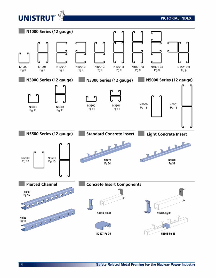
N1000Pg 9
N1001Pg 9
N1001APg 9
N1001BPg 9
N1001 A3Pg 9
N1001 3Pg 9
N1001CPg 9
N3000Pg 11
N3001Pg 11
N3300Pg 11
N3301Pg 11
N1000 Series (12 gauge)
N3000 Series (12 gauge) N3300 Series (12 gauge)
N5000Pg 13
N5001Pg 13
HolesPg 15
SlotsPg 15
N5500Pg 13
N5501Pg 13
N5000 Series (12 gauge)
Pierced Channel
N5500 Series (12 gauge)
N3270Pg 34
N3349-Pg 35
N3370Pg 34
N1703-Pg 35
N2407-Pg 35 N3663-Pg 35
Standard Concrete Insert Light Concrete Insert
Concrete Insert Components
N1001 C3Pg 9
PICTORIAL INDEX
Safety Related Metal Framing for the Nuclear Power Industry 5
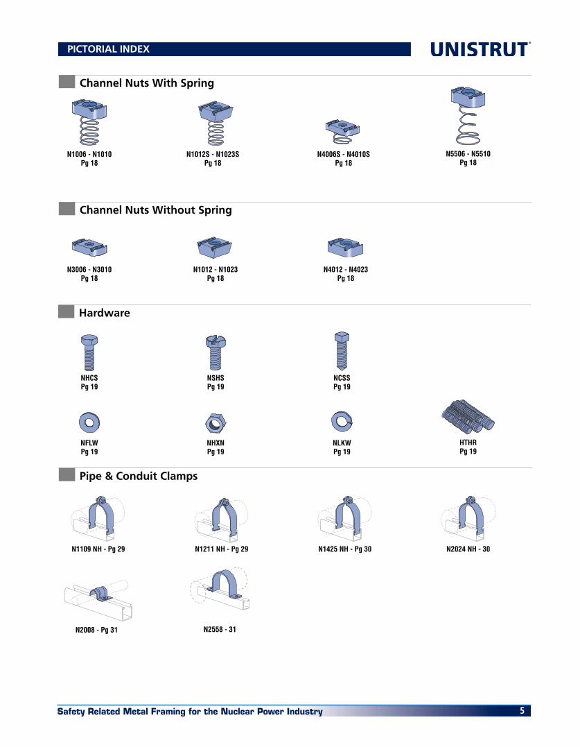
Channel Nuts With Spring
Channel Nuts Without Spring
Hardware
N1006 - N1010Pg 18
N1012S - N1023SPg 18
N4006S - N4010SPg 18
N5506 - N5510Pg 18
N3006 - N3010Pg 18
N1012 - N1023Pg 18
N4012 - N4023Pg 18
NHCSPg 19
NSHSPg 19
NCSSPg 19
HTHRPg 19
NFLWPg 19
NLKWPg 19
NHXNPg 19
N1109 NH - Pg 29 N1211 NH - Pg 29 N1425 NH - Pg 30 N2024 NH - 30
N2008 - Pg 31 N2558 - 31
Pipe & Conduit Clamps
PICTORIAL INDEX

Safety Related Metal Framing for the Nuclear Power Industry6
®
N1382- Pg 22
Flat Plate Fittings
Angle Fittings
N1062-Pg 20 N1959-Pg 20 N2862-Pg 20 N1065-Pg 21 N1924-Pg 21 N2324-Pg 22 N1066-Pg 21
N1925-Pg 21 N1067-Pg 21 N2079-Pg 22 N1941-Pg 21 N1036-Pg 20 N1380 A-Pg 21 N1380-Pg 21
N1873-Pg 21 N1031-Pg 20 N1028-Pg 20 N1356-Pg 21 N1358-Pg 21 N1726-Pg 21 N1950-Pg 22
N1026-Pg 22 N1458-Pg 22 N1750-Pg 22 N1325-Pg 22N1326-Pg 22 N1346-Pg 22
N1359-Pg 22 N1956-Pg 23
N1186-Pg 23
N1957-Pg 23 N2484W-Pg 23
N1546-Pg 23
N2469-Pg 24N3045-Pg 24 N4045-Pg 24N3345-Pg 24 N5545-Pg 24N1347-Pg 23N1045-Pg 23 N1453-Pg 23
"Z" Shape Fittings
N1068-Pg 22 N2235-Pg 23
GENERAL SPECIFICATIONS

Safety Related Metal Framing for the Nuclear Power Industry 7
N4377-Pg 25
N1383-Pg 25
N4376A-Pg 25 N1377-Pg 24N4376-Pg 25N1376-Pg 24 N1376A-Pg 24
N5547-Pg 26
N3047-Pg 25
N4047-Pg 25
N2224-Pg 26
N2473-Pg 25
N5543-Pg 26 N1048-Pg 24 N1737-Pg 24
N2328-Pg 25N2326-Pg 25
N2343-Pg 26
N2329-Pg 25
N2223-Pg 26
N2346-Pg 26 N2347-Pg 26
N2227-Pg 26N2225-Pg 26
N2229-Pg 26
N2228-Pg 26
N2345-Pg 26
N2073A-Pg 27N2072A-Pg 27
"U" Shape Fittings
Wing Shape Fittings
Post Bases and Brackets
N1047-Pg 24
N1834-Pg 25 N1834A-Pg 25
N2398NH-Pg 33N1648NH-Pg 33N2676NH-Pg 32N2675NH-Pg 32
N1796NH-Pg 32
N1271NH-Pg 32
N1379NH-Pg 33 N1272NH-Pg 33N1386-Pg 33
Beam Clamps
N1280 - Pg 27
P2944-Pg 28P2814NH-Pg 27 P2815DNH-Pg 27 P2542-Pg 28
N1000® SERIES CHANNEL & COMBINATIONS

Safety Related Metal Framing for the Nuclear Power Industry8
®
FRAMING MEMBERS
Unistrut channels and continuous inserts are accurately and carefully cold-formed to size from low carbon strip steel. One side of the channel has a continuous slot with inturned edges. Secure attachments may be made to the framing member with the use of hardened, toothed, slot-ted nuts which engage the inturned edges.
Raw steel shall conform to the following specifications.
FITTINGS
Unistrut fittings, unless noted otherwise, are punch-press made from hot rolled, pickled and oiled steel plates, strip, or coil and conform to ASTM specifications A575, A576. The fitting steel also meets the physical requirement of ASTM A1011SS GR 33. The pickling of the steel produces a smooth surface free from scale.
NUTS AND BOLTS
Unistrut nuts are made from steel coils or bars. After all machining operations are complete, they are thoroughly case hardened. Nuts are rectangular with ends shaped to permit a quarter turn clockwise in the framing member after insertion through the slotted opening in the channel. Two toothed grooves in the top of the nut engage the in-turned edges of the channel and, after bolting operations are completed, will prevent any movement of the bolt and nut within the framing member. All bolts and nuts have Unified and American coarse screw threads. The standard framing nut is 1⁄2” and conforms to ASTM Specification A576 GR 1015 (modified). Machine screws & hex head screws conform to SAE J429 GR 2 (also meets and exceeds ASTM A307).
FINISHES
PERMA-GREEN® II (GR)Channel and parts are carefully cleaned and phosphated. Immediately after phosphating, a uniform coat of a highly effective rust-inhibiting acrylic enamel paint is applied by electro-deposition and thoroughly baked. Color is Perma-Green per Federal Standard 595a color number 14109 (dark limit V-). The resulting finish will withstand 400 hours of salt spray when tested in accordance with ASTM designa-tion B-117.
ELECTRO-GALVANIZED (EG)Parts, screws and nuts are coated with zinc electrolytically to commercial standards (ASTM - B633 Type III SC1).
PRE-GALVANIZED (PG)Material (steel strip) is coated with zinc by hot-dip process prior to roll-forming or press operations. The zinc coating weight is G90 conforming to ASTM Specification A653 GR 33.
HOT-DIPPED GALVANIZED (HG)Material is coated with zinc after being roll-formed or after all manufacturing operations are completed, conforming to ASTM specification No. A123 for large items and A153 for centrifuged parts such as fasteners & small fittings.
SPECIAL METALSUnistrut channel is also available in stainless steel per ASTM A240 (Type 304). Contact Unistrut for details.
WEIGHTS AND DIMENSIONS
Weights given for all materials are approximate shipping weights. All dimensions subject to commercial tolerance within published specifications.
COMMERCIAL GRADE
See Unistrut General Engineering Catalog for commercial grade products.
CRITICAL CHARACTERISTICS
For critical characteristics of Safety Related Products, see Section “C” of Unistrut’s Quality Assurance Manual.
WE RESERVE THE RIGHT TO MAKE SPECIFICATION CHANGES WITH-
OUT NOTICE .
WHILE EVERY EFFORT HAS BEEN MADE TO ASSURE THE ACCURACY OF
INFORMATION CONTAINED IN THIS CATALOG AT THE TIME OF PUB-
LICATION, WE CANNOT ACCEPT RESPONSIBILITY FOR INACCURACIES
RESULTING FROM UNDETECTED ERRORS OR OMISSIONS.
THE BLUE COLOR USED ON UNISTRUT COMPONENTS ILLUSTRATED
IN THIS CATALOG IS FOR GRAPHIC ENHANCEMENT ONLY, AND DOES
NOT REPRESENT ACTUAL PRODUCT COLOR.
GENERAL SPECIFICATIONS
GAGE FINISH ASTM NO. 12 GR & HG A1011SS GR 33 PG A653 GR 33
14 GR & HG A1011SS GR 33 PG A653 GR 33
Safety Related Metal Framing for the Nuclear Power Industry 9
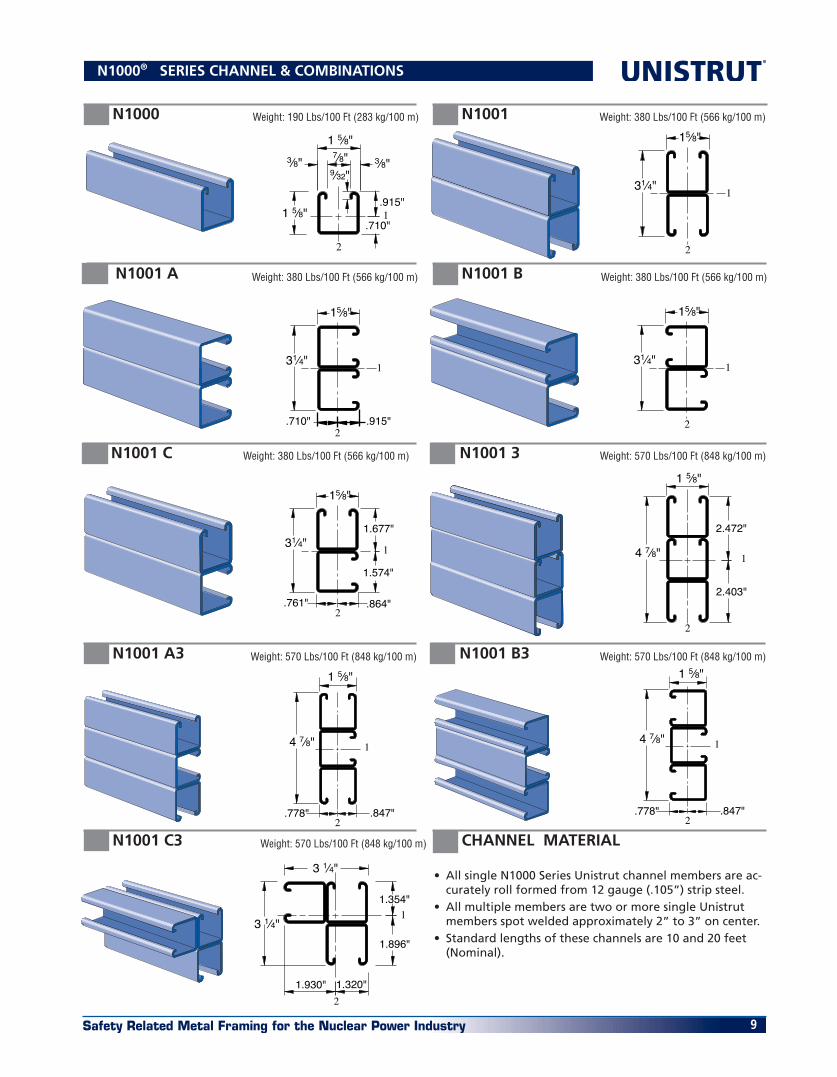
N1000® SERIES CHANNEL & COMBINATIONS
N1000 N1001
N1001 B
N1001 C
N1001 A
Weight: 190 Lbs/100 Ft (283 kg/100 m)
Weight: 380 Lbs/100 Ft (566 kg/100 m) Weight: 380 Lbs/100 Ft (566 kg/100 m)
Weight: 380 Lbs/100 Ft (566 kg/100 m)
Weight: 380 Lbs/100 Ft (566 kg/100 m)
.915"
.710"
2
1
9⁄32"
1 5⁄8"3⁄8"3⁄8"
1 5⁄8"
7⁄8"
1
2
15⁄8"
31⁄4"�
1
2
15⁄8"
31⁄4"�
2.915".710"
1
15⁄8"
31⁄4"�
2
15⁄8"
31⁄4" 1
1.677"
1.574"
.761" .864"
�
N1001 3 Weight: 570 Lbs/100 Ft (848 kg/100 m)
4 7⁄8"
1 5⁄8"
1
2
2.403"
2.472"
N1001 A3 Weight: 570 Lbs/100 Ft (848 kg/100 m)
N1001 C3 Weight: 570 Lbs/100 Ft (848 kg/100 m)
N1001 B3
2
1
1.320"
1.354"
1.896"
1.930"
3 1⁄4"
3 1⁄4"
2
1 5⁄8"
4 7⁄8" 1
.847".778"
1 5⁄8"
4 7⁄8" 1
2.847".778"
• All single N1000 Series Unistrut channel members are ac-curately roll formed from 12 gauge (.105”) strip steel.
• All multiple members are two or more single Unistrut members spot welded approximately 2” to 3” on center.
• Standard lengths of these channels are 10 and 20 feet (Nominal).
CHANNEL MATERIAL
Weight: 570 Lbs/100 Ft (848 kg/100 m)

Safety Related Metal Framing for the Nuclear Power Industry10
®
Resistance to Slip – 1500 Lbs. per bolt, Pull Out Strength – 2000 Lbs. per bolt, Includes a minimum Safety Factor of 3
N1010 NUT STRENGTH (USED IN N1000 CHANNEL)
I – Moment of Inertia; S – Section Modulus; r – Radius of Gyration
ELEMENTS OF SECTION
BEAM AND COLUMN DATA
N1000® SERIES CHANNEL & COMBINATIONS
Loads calculated using AISI “Cold-Formed Steel Design Manual (1996 edition).” Due to changes intro-duced in this manual, values may differ from those shown in previous Unistrut Nuclear catalogs.
CHANNEL FINISHES
Special finishes avail-able upon request.
Finishes Channel GR HG PG N1000 ■ ■ ■ N1001 ■ ■ ■
N1001 A ■ ■ ■ N1001 B ■ ■ ■
N1001 C ■ ■ ■ N1001 3 ■ ■ ■
N1001 A3 ■ ■ ■ N1001 B3 ■ ■ ■
N1001 C3 ■ ■ ■
Area of Wt./Ft. Sect. Axis 1-1 Axis 2-2 Channel Lbs. In.2 I (In.4) S (In.3) r(In.) I (In.4) S (In.3) r(In.) N1000 1.89 0.556 0.185 0.202 0.577 0.236 0.290 0.651 N1001 3.78 1.112 0.930 0.572 0.915 0.472 0.580 0.651 N1001C3 5.67 1.667 1.410 0.744 0.920 1.515 0.785 0.953 N10013 3.78 1.112 0.930 0.572 0.915 0.472 0.580 0.651
Notes: 1. Above loads include the weight of the member. This weight must be deducted to arrive at the net allowable load the beam will support. 2. Long span beams should be supported in such a manner as to prevent rotation and twist. See Page 16 3. Allowable uniformly distributed loads are listed for various simple spans, that is, a beam on two supports. If load is concentrated at the center of the span, multiply load from the table by 0.5 and corresponding deflection by 0.8. 4. Column loadings are for allowable axial loads for the unsupported heights listed with a K value of 0.80.
*Load limited by spot weld shear.
Maximum Unbraced Allowable Load Max. Col. Load Applied at C.G. Height at Slot Face K = 0.65 K = 0.80 K =1.0 K = 1.2 In Lbs Lbs Lbs Lbs Lbs
24 6,430 25,060 24,620 23,900 23,050 36 6,230 24,000 23,050 21,570 19,890 48 5,950 22,590 21,030 18,690 16,170 60 5,620 20,890 18,690 15,540 12,400 72 5,240 18,990 16,170 12,400 8,960 84 4,830 16,970 13,640 9,470 6,580 96 4,390 14,900 11,200 7,250 5,040 108 3,930 12,860 8,960 5,730 3,980 120 3,510 10,910 7,250 4,640 KL⁄r > 200
BEAM LOADING – N1001
Max Defl. at Allowable Uniform Uniform Loading at Defl. Span Uniform Load Load Span/180 Span/240 Span/360 In Lbs In Lbs Lbs Lbs
24 3,130 * 0.03 3,130 * 3,130 * 3,130 * 36 3,130 * 0.07 3,130 * 3,130 * 3,130 * 48 2,400 0.13 2,400 2,400 2,400 60 1,920 0.20 1,920 1,920 1,630 72 1,600 0.28 1,600 1,600 1,130 84 1,370 0.39 1,370 1,240 830 96 1,200 0.50 1,200 950 640 108 1,070 0.64 1,000 750 500 120 960 0.79 810 610 410
COLUMN LOADING – N1001
Maximum Unbraced Allowable Load Max. Col. Load Applied at C.G. Height at Slot Face K = 0.65 K = 0.80 K =1.0 K = 1.2 In Lbs Lbs Lbs Lbs Lbs
24 3,450 10,750 9,900 8,770 7,730 36 3,050 8,910 7,730 6,370 5,280 48 2,660 7,250 5,980 4,660 3,770 60 2,290 5,890 4,660 3,600 2,940 72 2,000 4,800 3,770 2,940 2,380 84 1,760 4,010 3,170 2,460 1,970 96 1,570 3,450 2,730 2,090 1,650 108 1,410 3,020 2,380 1,800 KL⁄r > 200 120 1,270 2,680 2,090 KL⁄r > 200 KL⁄r > 200
BEAM LOADING – N1000
Max Defl. at Allowable Uniform Uniform Loading at Defl. Span Uniform Load Load Span/180 Span/240 Span/360 In Lbs In Lbs Lbs Lbs
24 1,690 0.06 1,690 1,690 1,690 36 1,130 0.13 1,130 1,130 900 48 850 0.22 850 760 510 60 680 0.35 650 490 320 72 560 0.50 450 340 220 84 480 0.68 330 250 170 96 420 0.89 250 190 130 108 380 1.13 200 150 100 120 340 1.40 160 120 80
COLUMN LOADING – N1000

Safety Related Metal Framing for the Nuclear Power Industry 11
N3000 & N3300 SERIES
CHANNEL & COMBINATIONS
N3000 Weight: 170 Lbs/100 Ft (253 kg/100 m) N3001 Weight: 340 Lbs/100 Ft (506 kg/100 m)
N3300 Weight: 135 Lbs/100 Ft (201 kg/100 m) N3301 Weight: 270 Lbs/100 Ft (402 kg/100 m)
• All single N3000 and N3300 Series Unistrut channel members are accurately roll formed from 12 gauge (.105”) strip steel.
• All multiple members are two or more single Unis-trut members spot welded approximately 2” to 3” on center.
• Standard lengths of these channels are 10 and 20 feet (Nominal).
CHANNEL FINISHES
1 3⁄8"
9⁄32"
1 5⁄8"7⁄8"3⁄8" 3⁄8"
.784"
2
1.591"
2 3⁄4"
1 5⁄8"
2
1
7⁄8"
1 5⁄8"3⁄8" 3⁄8"
7⁄8"
.517"
.358"
�9⁄32"
2
1
1 3⁄4"
1 5⁄8"
2
1
CHANNEL MATERIAL
ELEMENTS OF SECTION N1010 NUT STRENGTH (USED IN N3000 CHANNEL)
Resistance to Slip – 1500 Lbs. per bolt, Pull Out Strength – 2000 Lbs. per bolt, Includes a minimum Safety Factor of 3
N4010 NUT STRENGTH (USED IN N3300 CHANNEL)
Resistance to Slip – 1500 Lbs. per bolt, Pull Out Strength – 1500 Lbs. per bolt, Includes a minimum Safety Factor of 3
I – Moment of Inertia; S – Section Modulus; r – Radius of Gyration
Area of Wt./Ft. Sect. Axis 1-1 Axis 2-2 Channel Lbs. In.2 I (In.4) S (In.3) r(In.) I (In.4) S (In.3) r(In.) N3000 1.71 0.503 0.121 0.154 0.490 0.205 0.253 0.639 N3001 3.42 1.007 0.593 0.431 0.767 0.411 0.506 0.639 N3300 1.35 0.398 0.037 0.072 0.306 0.145 0.178 0.603 N3301 2.71 0.797 0.177 0.202 0.471 0.289 0.356 0.603
Special finishes avail-able upon request.
Finishes Channel GR HG PG N3000 ■ ■ ■ N3001 ■ ■ ■
N3300 ■ ■ ■ N3301 ■ ■ ■
Safety Related Metal Framing for the Nuclear Power Industry12
® N3000 & N3300 SERIES CHANNEL & COMBINATIONS
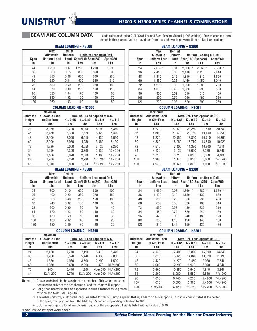
BEAM AND COLUMN DATA Loads calculated using AISI “Cold-Formed Steel Design Manual (1996 edition).” Due to changes intro-duced in this manual, values may differ from those shown in previous Unistrut Nuclear catalogs.
BEAM LOADING – N3000 Max Defl. at Allowable Uniform Uniform Loading at Defl. Span Uniform Load Load Span/180 Span/240 Span/360 In Lbs In Lbs Lbs Lbs
24 1,290 0.07 1,290 1,290 1,290 36 860 0.15 860 860 590 48 650 0.26 650 500 330 60 520 0.41 420 320 210 72 430 0.59 290 220 150 84 370 0.80 220 160 110 96 320 1.04 170 120 80 108 290 1.32 130 100 70 120 260 1.63 110 80 50
COLUMN LOADING – N3000 Maximum Unbraced Allowable Load Max. Col. Load Applied at C.G. Height at Slot Face K = 0.65 K = 0.80 K =1.0 K = 1.2 In Lbs Lbs Lbs Lbs Lbs
24 3,070 9,790 9,090 8,190 7,370 36 2,730 8,300 7,370 6,320 5,440 48 2,400 7,000 6,010 4,930 4,050 60 2,090 5,930 4,930 3,860 3,120 72 1,820 5,060 4,050 3,120 2,290 84 1,590 4,300 3,390 2,430 KL⁄r > 200 96 1,400 3,690 2,880 1,860 KL⁄r > 200 108 1,200 3,220 2,290 KL⁄r > 200 KL⁄r > 200 120 1,040 2,820 1,860 KL⁄r > 200 KL⁄r > 200
BEAM LOADING – N3001
COLUMN LOADING – N3001 Maximum Unbraced Allowable Load Max. Col. Load Applied at C.G. Height at Slot Face K = 0.65 K = 0.80 K =1.0 K = 1.2 In Lbs Lbs Lbs Lbs Lbs
24 5,720 22,670 22,250 21,580 20,780 36 5,500 21,670 20,780 19,400 17,830 48 5,220 20,350 18,890 16,710 14,390 60 4,880 18,760 16,710 13,800 10,920 72 4,510 17,000 14,390 10,920 7,810 84 4,120 15,120 12,050 8,270 5,740 96 3,710 13,210 9,820 6,330 4,400 108 3,300 11,340 7,810 5,000 KL⁄r > 200 120 2,940 9,560 6,330 4,050 KL⁄r > 200
COLUMN LOADING – N3301 Maximum Unbraced Allowable Load Max. Col. Load Applied at C.G. Height at Slot Face K = 0.65 K = 0.80 K =1.0 K = 1.2 In Lbs Lbs Lbs Lbs Lbs
24 4,130 17,400 16,820 15,900 14,840 36 3,810 16,020 14,840 13,070 11,190 48 3,420 14,270 12,450 9,930 7,540 60 3,000 12,290 9,930 6,970 4,840 72 2,590 10,250 7,540 4,840 3,360 84 2,200 8,260 5,550 3,550 KL⁄r > 200 96 1,890 6,440 4,250 KL⁄r > 200 KL⁄r > 200 108 1,630 5,090 3,360 KL⁄r > 200 KL⁄r > 200 120 KL/r>200 4,120 KL⁄r > 200 KL⁄r > 200 KL⁄r > 200
BEAM LOADING – N3301 Max Defl. at Allowable Uniform Uniform Loading at Defl. Span Uniform Load Load Span/180 Span/240 Span/360 In Lbs In Lbs Lbs Lbs
24 1,660 * 0.06 1,660 * 1,660 * 1,660 * 36 1,130 0.13 1,130 1,130 860 48 850 0.23 850 730 480 60 680 0.36 620 460 310 72 560 0.53 430 320 210 84 480 0.72 320 240 160 96 420 0.93 240 180 120 108 380 1.18 190 140 100 120 340 1.46 150 120 80
Maximum Unbraced Allowable Load Max. Col. Load Applied at C.G. Height at Slot Face K = 0.65 K = 0.80 K =1.0 K = 1.2 In Lbs Lbs Lbs Lbs Lbs
24 2,120 7,710 7,190 6,410 5,440 36 1,760 6,520 5,440 4,030 2,830 48 1,380 4,960 3,590 2,290 1,590 60 1,060 3,480 2,290 1,470 KL/r>200 72 840 2,410 1,590 KL/r>200 KL/r>200 84 KL/r>200 1,770 KL/r>200 KL/r>200 KL/r>200
BEAM LOADING – N3300 Max Defl. at Allowable Uniform Uniform Loading at Defl. Span Uniform Load Load Span/180 Span/240 Span/360 In Lbs In Lbs Lbs Lbs
24 600 0.10 600 600 400 36 400 0.22 360 270 180 48 300 0.40 200 150 100 60 240 0.62 130 100 60 72 200 0.90 90 70 40 84 170 1.22 70 50 30 96 150 1.59 50 40 30 108 130 2.02 40 30 20 120 120 2.49 30 20 20
Max Defl. at Allowable Uniform Uniform Loading at Defl. Span Uniform Load Load Span/180 Span/240 Span/360 In Lbs In Lbs Lbs Lbs
24 2,660 * 0.04 2,660 * 2,660 * 2,660 * 36 2,410 0.08 2,410 2,410 2,410 48 1,810 0.15 1,810 1,810 1,620 60 1,450 0.23 1,450 1,450 1,040 72 1,200 0.33 1,200 1,080 720 84 1,030 0.46 1,030 790 530 96 900 0.59 810 610 400 108 800 0.75 640 480 320 120 720 0.93 520 390 260
Notes: 1. Above loads include the weight of the member. This weight must be deducted to arrive at the net allowable load the beam will support. 2. Long span beams should be supported in such a manner as to prevent rotation and twist. See Page 16. 3. Allowable uniformly distributed loads are listed for various simple spans, that is, a beam on two supports. If load is concentrated at the center of the span, multiply load from the table by 0.5 and corresponding deflection by 0.8. 4. Column loadings are for allowable axial loads for the unsupported heights listed with a K value of 0.80.*Load limited by spot weld shear.
COLUMN LOADING – N3300
Safety Related Metal Framing for the Nuclear Power Industry 13
N5000 & N5500 SERIES CHANNEL & COMBINATIONS
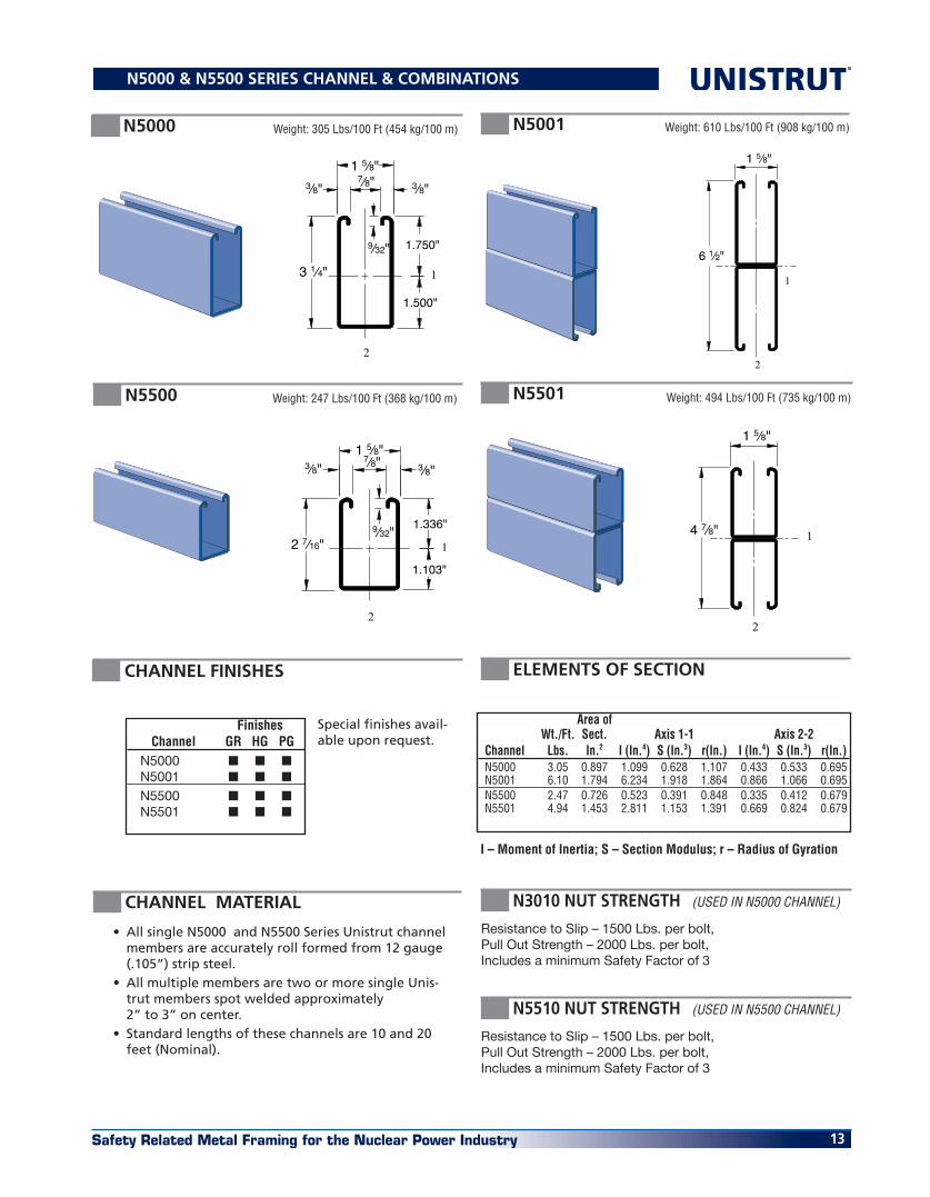
N5000 Weight: 305 Lbs/100 Ft (454 kg/100 m) N5001 Weight: 610 Lbs/100 Ft (908 kg/100 m)
N5500 Weight: 247 Lbs/100 Ft (368 kg/100 m) N5501 Weight: 494 Lbs/100 Ft (735 kg/100 m)
12 7⁄16"9⁄32"
1.103"
1.336"
1 5⁄8"3⁄8" 3⁄8"
7⁄8"
2
4 7⁄8"
1 5⁄8"
2
1
6 1⁄2"
1 5⁄8"
2
113 1⁄4"
1 5⁄8"3⁄8" 3⁄8"
7⁄8"
9⁄32" 1.750"
1.500"
2
• All single N5000 and N5500 Series Unistrut channel members are accurately roll formed from 12 gauge (.105”) strip steel.
• All multiple members are two or more single Unis-trut members spot welded approximately 2” to 3” on center.
• Standard lengths of these channels are 10 and 20 feet (Nominal).
N3010 NUT STRENGTH (USED IN N5000 CHANNEL)
Resistance to Slip – 1500 Lbs. per bolt, Pull Out Strength – 2000 Lbs. per bolt, Includes a minimum Safety Factor of 3
I – Moment of Inertia; S – Section Modulus; r – Radius of Gyration
ELEMENTS OF SECTIONCHANNEL FINISHES
Special finishes avail-able upon request.
Finishes Channel GR HG PG N5000 ■ ■ ■ N5001 ■ ■ ■
N5500 ■ ■ ■ N5501 ■ ■ ■
Area of Wt./Ft. Sect. Axis 1-1 Axis 2-2 Channel Lbs. In.2 I (In.4) S (In.3) r(In.) I (In.4) S (In.3) r(In.) N5000 3.05 0.897 1.099 0.628 1.107 0.433 0.533 0.695 N5001 6.10 1.794 6.234 1.918 1.864 0.866 1.066 0.695 N5500 2.47 0.726 0.523 0.391 0.848 0.335 0.412 0.679 N5501 4.94 1.453 2.811 1.153 1.391 0.669 0.824 0.679
CHANNEL MATERIAL
N5510 NUT STRENGTH (USED IN N5500 CHANNEL)
Resistance to Slip – 1500 Lbs. per bolt, Pull Out Strength – 2000 Lbs. per bolt, Includes a minimum Safety Factor of 3

Safety Related Metal Framing for the Nuclear Power Industry14
®
BEAM AND COLUMN DATA Loads calculated using AISI “Cold-Formed Steel Design Manual (1996 edition).” Due to changes intro-duced in this manual, values may differ from those shown in previous Unistrut Nuclear catalogs.
N5000 & N5500 SERIES CHANNEL & COMBINATIONS
COLUMN LOADING – N5000 Unbraced Max. Allowable Max. Col. Load Applied at C.G. Height Load at Slot Face K = 0.65 K = 0.80 K =1.0 K = 1.2 In Lbs Lbs Lbs Lbs Lbs 24 4,430 13,050 12,000 11,180 9,590 36 4,030 11,380 9,590 7,390 5,560 48 3,400 8,830 6,730 4,700 3,560 60 2,780 6,580 4,700 3,360 2,620 72 2,330 4,890 3,560 2,620 2,090 84 2,010 3,860 2,870 2,160 1,750 96 1,770 3,180 2,410 1,850 1,510 108 1,590 2,710 2,090 1,620 1,330 120 1,440 2,370 1,850 1,450 **
BEAM LOADING – N5000 Max Defl. at Allowable Uniform Uniform Loading at Defl. Span Uniform Load Load Span/180 Span/240 Span/360 In Lbs In Lbs Lbs Lbs 24 5,260 0.03 5,260 5,260 5,260 36 3,510 0.07 3,510 3,510 3,510 48 2,630 0.12 2,630 2,630 2,630 60 2,110 0.18 2,110 2,110 1,920 72 1,750 0.26 1,750 1,750 1,330 84 1,500 0.36 1,500 1,470 980 96 1,320 0.47 1,320 1,130 750 108 1,170 0.59 1,170 890 590 120 1,050 0.73 960 720 480 144 880 1.05 670 500 330 168 750 1.43 490 370 250 192 660 1.87 380 280 190 216 580 2.37 300 220 150 240 530 2.92 240 180 120
COLUMN LOADING – N5001 Unbraced Max. Allowable Max. Col. Load Applied at C.G. Height Load at Slot Face K = 0.65 K = 0.80 K =1.0 K = 1.2 In Lbs Lbs Lbs Lbs Lbs 24 8,360 30,190 29,820 29,220 28,500 36 8,230 29,300 28,500 27,220 25,740 48 8,050 28,100 26,750 24,660 22,320 60 7,810 26,630 24,660 23,090 19,770 72 7,530 24,930 22,320 19,770 15,800 84 7,340 23,070 21,110 16,450 12,100 96 6,950 22,440 18,430 13,300 9,260 108 6,510 20,270 15,800 10,540 7,320 120 6,010 18,100 13,300 8,540 KL⁄r > 200
BEAM LOADING – N5001 Max Defl. at Allowable Uniform Uniform Loading at Defl. Span Uniform Load Load Span/180 Span/240 Span/360 In Lbs In Lbs Lbs Lbs 24 6,170 * 0.02 6,170 * 6,170 * 6,170 * 36 6,170 * 0.04 6,170 * 6,170 * 6,170 * 48 6,170 * 0.06 6,170 * 6,170 * 6,170 * 60 6,170 * 0.10 6,170 * 6,170 * 6,170 * 72 5,360 0.14 5,360 5,360 5,360 84 4,590 0.19 4,590 4,590 4,590 96 4,020 0.25 4,020 4,020 4,020 108 3,570 0.32 3,570 3,570 3,360 120 3,220 0.39 3,220 3,220 2,720 144 2,680 0.57 2,680 2,680 1,890 168 2,300 0.77 2,300 2,090 1,390 192 2,010 1.01 2,010 1,600 1,060 216 1,790 1.27 1,680 1,260 840 240 1,610 1.57 1,360 1,020 680
BEAM LOADING – N5501 Max Defl. at Allowable Uniform Uniform Loading at Defl. Span Uniform Load Load Span/180 Span/240 Span/360 In Lbs In Lbs Lbs Lbs 24 4,680 * 0.02 4,680 * 4,680 * 4,680 * 36 4,680 * 0.05 4,680 * 4,680 * 4,680 * 48 4,680 * 0.08 4,680 * 4,680 * 4,680 * 60 3,870 0.13 3,870 3,870 3,870 72 3,220 0.19 3,220 3,220 3,220 84 2,760 0.26 2,760 2,760 2,510 96 2,420 0.34 2,420 2,420 1,920 108 2,150 0.42 2,150 2,150 1,520 120 1,930 0.52 1,930 1,840 1,230 144 1,610 0.76 1,610 1,280 850 168 1,380 1.03 1,250 940 630 192 1,210 1.34 960 720 480 216 1,070 1.70 760 570 380 240 970 2.10 610 460 310
COLUMN LOADING – N5501 Unbraced Max. Allowable Max. Col. Load Applied at C.G. Height Load at Slot Face K = 0.65 K = 0.80 K =1.0 K = 1.2 In Lbs Lbs Lbs Lbs Lbs 24 8,650 32,840 32,310 31,440 30,410 36 8,450 31,560 30,410 28,610 26,550 48 8,180 29,850 27,950 25,070 21,960 60 7,830 27,780 25,070 21,160 17,200 72 7,420 25,450 21,960 17,200 12,730 84 6,940 22,950 18,770 13,460 9,350 96 6,410 20,360 15,660 10,310 7,160 108 5,810 17,780 12,730 8,150 5,660 120 5,220 15,280 10,310 6,600 KL⁄r > 200
BEAM LOADING – N5500
COLUMN LOADING – N5500 Unbraced Max. Allowable Max. Col. Load Applied at C.G. Height Load at Slot Face K = 0.65 K = 0.80 K =1.0 K = 1.2 In Lbs Lbs Lbs Lbs Lbs
24 4,580 13,860 12,610 10,910 9,300 36 4,010 11,120 9,300 7,190 5,550 48 3,370 8,550 6,580 4,800 3,800 60 2,810 6,430 4,800 3,610 2,920 72 2,410 4,970 3,800 2,920 2,390 84 2,120 4,060 3,160 2,460 2,020 96 1,900 3,450 2,720 2,130 1,740 108 1,720 3,000 2,390 1,870 1,520 120 1,570 2,670 2,130 1,660 KL⁄r > 200
Max Defl. at Allowable Uniform Uniform Loading at Defl. Span Uniform Load Load Span/180 Span/240 Span/360 In Lbs In Lbs Lbs Lbs 24 3,280 0.04 3,280 3,280 3,280 36 2,190 0.09 2,190 2,190 2,190 48 1,640 0.15 1,640 1,640 1,430 60 1,310 0.24 1,310 1,310 910 72 1,090 0.34 1,090 950 630 84 940 0.47 930 700 470 96 820 0.61 710 540 360 108 730 0.77 560 420 280 120 660 0.96 460 340 230 144 550 1.38 320 240 160 168 470 1.87 230 170 120 192 410 2.45 180 130 90 216 360 3.10 140 110 70 240 330 3.82 110 90 60
Notes: 1. Above loads include the weight of the member. This weight must be deducted to arrive at the net allowable load the beam will support. 2. Long span beams should be supported in such a manner as to prevent rotation and twist. See Page 16. 3. Allowable uniformly distributed loads are listed for various simple spans, that is, a beam on two supports. If load is concentrated at the center of the span, multiply load from the table by 0.5 and corresponding deflection by 0.8. 4. Column loadings are for allowable axial loads for the unsupported heights listed with a K value of 0.80.*Load limited by spot weld shear. #: Bearing load may govern capacity. See Page 16.

Safety Related Metal Framing for the Nuclear Power Industry 15
CHANNELS WITH SLOTS OR HOLES
9⁄16" (14.3) Dia. Holes�1 7⁄8" (47.6) on Center D
��
Slots are 9⁄16" (14.3) Wide x 11⁄8" (28.6)�2" (51) on Center
D
“T” SERIES – SLOTTED
“HS” SERIES – HOLES
Note: For beam load capacity, use 85% of appropriate load chart.
Note: For beam load capacity, use 95% of appropriate load chart.
Standard Lengths: 10’ and 20’.
Standard Lengths: 10’ and 20’.
Material Part Depth “D” Thicknesses Weight Number In. mm. In. mm. Lbs/100 Ft. kg/100 m N1000 T 15⁄8 41 .105 2.7 185 275 N3000 T 13⁄8 35 .105 2.7 165 245 N3300 T 7⁄8 22 .105 2.7 130 193 N5000 T 31⁄4 82 .105 2.7 300 446 N5500 T 27⁄16 62 .105 2.7 242 360
Material Part Depth “D” Thicknesses Weight Number In. mm. In. mm. Lbs/100 Ft. kg/100 m N1000 HS 15⁄8 41 .105 2.7 185 275 N3000 HS 1-3⁄8 35 .105 2.7 165 246 N3300 HS 7⁄8 22 .105 2.7 130 193 N5000 HS 31⁄4 82 .105 2.7 300 446 N5500 HS 27⁄16 62 .105 2.7 242 360

Safety Related Metal Framing for the Nuclear Power Industry16
®
0
20
40
60
80
100
10
30
50
70
90
% O
F AL
LOW
ABLE
LO
AD R
ETAI
NED
1201089684726048362412
DISTANCE (In)�BETWEEN LATERAL BRACES
N3300N3000N1000
N5500N5000
▲
▲▲
▲
▲
▲
▲
▲
▲
▲
▲
0
20
40
60
80
100
10
30
50
70
90
% O
F AL
LOW
ABLE
LO
AD R
ETAI
NED
1201089684726048362412
DISTANCE (In)BETWEEN LATERAL BRACES
▲
▲
▲▲
▲▲
▲▲▲
▲
▲
▲
▲
▲
▲
▲▲
▲▲
▲
N3301N1001
N5501N5001▲
▲
LATERAL BRACING LOAD REDUCTION CHARTS
ENGINEERING DATA DESIGN LOADS
Bearing Length 15⁄8” (41 mm) Bearing Length 15⁄8” (41 mm) Bearing Length 31⁄4” (82 mm)
Maximum Allowable Loads Maximum Allowable Loads Maximum Allowable Loads Channel Lbs Kn Lbs Kn Lbs Kn N1000 5,000 22.2 3,500 15.6 8,000 35.6 N3000 5,000 22.2 3,500 15.6 8,000 35.6 N3300 6,000 26.7 4,000 17.8 9,000 35.6 N5000 4,000 17.8 2,000 8.9 5,500 24.6 N5500 5,000 22.2 3,500 15.6 8,000 35.6
BEARING LOADS ON UNISTRUT CHANNEL
Safety Factor — 21⁄2 LOAD
LOAD LOAD

Safety Related Metal Framing for the Nuclear Power Industry 17
Both ends of beams supported.
Load data is based on N1010 nut and 1⁄2” bolt.
Safety factor = 21⁄2 based on ultimate strength of connection.
DESIGN LOAD DATA FOR TYPICAL UNISTRUT CHANNEL CONNECTIONS
ENGINEERING DATA DESIGN LOADS
LOAD
LOAD
LOADLOADLOAD
LOAD
LOADLOAD
LOADLOAD
90° Fittings (When used in position shown)
N2484 N1068 N1326 N1346 N1065 Channel Thickness Lbs kN Lbs kN Lbs kN Lbs kN Lbs kN
12 ga. 3000 13.3 500 2.2 500 2.2 1200 5.3 1000 4.4
90° Fittings (When used in position shown) N1325
N1026 N1026 N2235 N1458 N1346 Channel Thickness Lbs kN Lbs kN Lbs kN Lbs kN Lbs kN
12 ga. 1500 6.7 1000 4.4 2000 8.9 1500 6.7 2000 8.9

Safety Related Metal Framing for the Nuclear Power Industry18
®
N4012 – N4023
N1012 – N1023
N3006-1420 – N3010
Note: Use With N1000, N3000, N3300, N5000 and N5500 Channels.
* Not for use with N3300
Note: Use with N3300 channels.
Note: Use with N1000, N3000, N5000 & N5500 channels.
MATERIAL
Unistrut spring or springless nuts are manufactured from mild steel bars, and after machining operations are com-pleted, they are case hardened. Hardening assures posi-tive biting action into the inturned edge of the Unistrut channel. Nuts, bolts & washers are electro-galvanized, unless otherwise noted.
THREADS
All threads on the nuts & bolts are Unified & American screw threads, UNC classes 2A & 2B. The threads on Unis-trut nuts are accepted at .002” over the 2B maximum limit.
DESIGN BOLT TORQUE
UNISTRUT NUTS
Channel Nuts with Springs
Channel Nuts with Springs
N1006-1420 THRU N1023S
N4006-1420 THRU N4010S
N5506-1420 THRU N5510
Note: Use with N5500 channels.
Note: Use with N3300 channels.
Note: Use with N1000 & N3000 channels.
BOLT�SIZEFOOT�LBS.N.m
1⁄4"�206
8
�3⁄8"�1619
25
5⁄8"�11
50
70
1⁄2"�13
100
135
3⁄4"�10
125
170
Note: Use with N1000 & N3000 channels.
Size & Weight/100 pcs. Part Number Thread lbs. kg N1006-1420 1⁄4” - 20 7 3.2 N1008 3⁄8” - 16 10 4.5 N1010 1⁄2” - 13 12 5.4
Size & Weight/100 pcs. Part Number Thread lbs. kg N1012S 5⁄8” - 11 21 9.5 N1023S 3⁄4” - 10 21 9.5
Size & Weight/100 pcs. Part Number Thread lbs. kg N4006-1420 1⁄4” - 20 7 3.2 N4008 3⁄8” - 16 9 4.1 N4010 1⁄2” - 13 8 3.6
Channel Nuts with Springs
Size & Weight/100 pcs. Part Number Thread lbs. kg N5506-1420 1⁄4” - 20 7 3.2 N5508 3⁄8” - 16 10 4.5 N5510 1⁄2” - 13 12 5.4
Channel Nuts without Springs Size & Weight/100 pcs. Part Number Thread lbs. kg N3006-1420 1⁄4” - 20 6 2.7 N3008 3⁄8” -16 9 4.1 N3010* 1⁄2” -13 8 3.6
Channel Nuts without Springs Size & Weight/100 pcs. Part Number Thread lbs. kg N1012 5⁄8” -11 20 9.1 N1023 3⁄4” -10 20 9.1
Channel Nuts without Springs Size & Weight/100 pcs. Part Number Thread lbs. kg N4012 5⁄8” -11 10 4.5 N4023 3⁄4” -10 10 4.5

Safety Related Metal Framing for the Nuclear Power Industry 19
UNISTRUT NUTS & HARDWARE
HEX HEAD CAP SCREWS
CONE POINT SET SCREWS
HEX SLOTTED MACHINE SCREWS
HEXAGON NUTS
Weight/100 pcs. Part Number Size lbs. kg NHCS025100EG 1⁄4” x 1” 1.5 0.7 NHCS037100EG 3⁄8” x 1” 4.5 2.0 NHCS050094EG 1⁄2” x 15⁄16” 9.1 4.1 NHCS050150EG 1⁄2” x 11⁄2” 11.6 5.3
Weight/100 pcs. Part Number Size lbs. kg NCSS037150EG 3⁄8” x 11⁄2” 6.0 2.7 NCSS037200EG 3⁄8” x 2” 6.1 2.8 NCSS050150EG 1⁄2” x 11⁄2” 8.5 3.9 NCSS050200EG 1⁄2” x 2” 11.4 5.2
Weight/100 pcs. Part Number Size lbs. kg NHXN025EG 1⁄4” 0.6 0.3 NHXN037EG 3⁄8” 1.6 0.7 NHXN050EG 1⁄2” 4.8 2.2
Weight/100 pcs. Part Number Size lbs. kg NSHS025075EG 1⁄4” x 3⁄4” 1.7 0.8 NSHS025100EG 1⁄4” x 1” 1.8 0.9 NSHS025125EG 1⁄4” x 11⁄4” 2.5 1.1 NSHS031100EG 5⁄16” x 1” 2.6 1.2 NSHS031125EG 5⁄16” x 11⁄4” 3.0 1.4 NSHS031137EG 5⁄16” x 13⁄8” 3.3 1.6 NSHS031175EG 5⁄16” x 13⁄4” 3.6 1.8 NSHS037125EG 3⁄8” x 11⁄4” 5.3 2.4
LOCK WASHERS
FLAT WASHERS
STEEL THREADED ROD
Weight/100 pcs. Part Number Size lbs. kg NTHR025 1⁄4” x 20 13 5.9 NTHR037 3⁄8” x 16 30 13.6 NTHR050 1⁄2” x 13 53 24.0
Weight/100 pcs. Part Number Size lbs. kg NFLW025EG 1⁄4” 0.8 0.4 NFLW037EG 3⁄8” 1.5 0.7 NFLW050EG 1⁄2” 3.5 1.6
Weight/100 pcs. Part Number Size lbs. kg NLKW025EG 1⁄4” 0.25 0.1 NLKW037EG 3⁄8” 0.63 0.3 NLKW050EG 1⁄2” 1.32 0.6
Standard Length 12' (3.7m)
Note: Standard 10’ length

Safety Related Metal Framing for the Nuclear Power Industry20
®
Weight: 105 Lbs/100 Pcs (47.6 kg) Weight: 80 Lbs/100 Pcs (36.3 kg) Weight: 58 Lbs/100 Pcs (26.3 kg)
5 3⁄8"(136.5)
(136.5)5 3⁄8"
(88.9)3 1⁄2"
5 3⁄8"(136.5)
(88.9)3 1⁄2"
3 1⁄2"(88.9)
DESIGN LOAD DATA
Design load data, where shown, is based on the ultimate strength of the connection with a safety factor of 2-1⁄2.
MATERIAL
Unless otherwise noted, all Unistrut fittings are punch press formed from hot rolled pickled and oiled plate or strip steel and conform to ASTM speci-fications A575 and A576.
STANDARD DIMENSIONS
The following dimensions apply to all fittings except as noted on the part drawings:
Fitting width: 1-5⁄8” Fitting thickness: 1⁄4” Hole size: 9⁄16” Diameter Hole spacing: 13⁄16” from end of fitting & 1-7⁄8” center to center
FITTINGS SPECIFICATIONS & FLAT PLATE
BOLT�SIZEFOOT�LBS.N.m
1⁄4"�206
8
�3⁄8"�1619
25
5⁄8"�11
50
70
1⁄2"�13
100
135
3⁄4"�10
125
170
N1062 THRU N1064N1964, N2471, N2490
N2862 THRU N2864 N1959 THRU N1961
N1036 N1031 N1028
1 1⁄2"(38.1) (34.9)
1 3⁄8"
Tapped Hole
Standard Square Washer
1 5⁄8"(41.3)
Anti–Rotation Washer Tapped Square Plate
Material 3⁄8” (9.5) thick.
1 5⁄8"(41.3)
Part Bolt Hole Wt./100 pcs. Number Size Size lbs. kg N1062 5⁄16” 11/32” 18 8.2 N1063 3⁄8” 7⁄16” 18 8.2 N1064 1⁄2” 9⁄16” 17 7.7 N2471 3⁄4” 13⁄16” 15 6.8
Part Bolt Hole Wt./100 pcs. Number Size Size lbs. kg N2862 5⁄16” 11/32” 18 8.2 N2863 3⁄8” 7⁄16” 18 8.2 N2864 1⁄2” 9⁄16” 17 7.7
Part US Std. Wt./100 pcs. Number Thd. Size lbs. kg N1959 3⁄8” - 16 21 9.5 N1960 1⁄2” - 13 20 9.1 N1961 5⁄8” - 11 19 8.6
DESIGN BOLT TORQUE
FLAT PLATE FITTINGS
FITTING APPLICATION
All part drawings illustrate only one application of each fitting. In most cases many other applications are possible. The Unistrut members shown in the illustration are N1000, 15⁄8” square, except where noted otherwise. All 9⁄16” diameter holes use 1⁄2” x 15⁄16” hex head cap screws and 1⁄2” Unistrut nuts – N1010 or N5510 – depending on the Unistrut channel used. Nuts & bolts are not included with the fitting and must be ordered separately.
FINISHES
All fittings in this section are available in:
• Perma-Green (GR), • Hot Dipped Galvanized (HG)• Electro Galvanized (EG).
Many fittings are also available in Stainless Steel (SS). Contact Unistrut for Availability.

Safety Related Metal Framing for the Nuclear Power Industry 21
Weight: 38 Lbs/100 Pcs (17.2 kg) Weight: 78 Lbs/100 (35.4kg)
Weight: 70 Lbs/100 Pcs (31.8 kg) Weight: 105 Lbs/100 Pcs (47.6 kg)
Weight: 56 Lbs/100 Pcs (25.4 kg)
3 1⁄2"(88.9)
5 3⁄8"(136.5)
7 1⁄4"(184.2)
3 1⁄2"(88.9)
3 1⁄2"(88.9)
5 3⁄8"(136.5)
(88.9)3 1⁄2"
Weight: 80 Lbs/100 Pcs (36.3 kg)
Weight: 105 Lbs/100 Pcs (47.6 kg)
5 3⁄8"(136.5)
3 1⁄2"(88.9)
(136.5)5 3⁄8"
3 1⁄2"(88.9)
(136.5)5 3⁄8"
5 3⁄8"(136.5)
Weight: 148 Lbs/100 Pcs (67.1 kg)
FLAT PLATE FITTINGS
N1066 N1067
N1358 N1356
N1065
N1380 A
N1380 N1726
Weight: 150 Lbs/100 Pcs (68.0 kg)
(136.5)5 3⁄8"
5 3⁄8"(136.5)
N1873
Weight: 50 Lbs/100 Pcs (22.7 kg) Weight: 94 Lbs/100 Pcs (42.6 kg)Weight: 35 Lbs/100 Pcs (15.9 kg)
4 7⁄8"(123.8)
(41.3)1 5⁄8"
(41.3)1 5⁄8"
9 1⁄8"(231.8)1 5⁄8"
(41.3)
(82.6)3 1⁄4"
N1924 N1925 N1941

Safety Related Metal Framing for the Nuclear Power Industry22
®
Weight: 105 Lbs/100 Pcs (47.6 kg)
Weight: 78 Lbs/100 Pcs (35.4 kg)
Weight: 58 Lbs/100 Pcs (26.3 kg) Weight: 58 Lbs/100 Pcs (26.3 kg)
4 1⁄8"(104.8)
(88.9)3 1⁄2"
(36.5)1 7⁄16"
4 1⁄8"(104.8)
(36.5)1 7⁄16"
3 7⁄8"(98.4)
(47.6)1 7⁄8" (41.3)
1 5⁄8"
4 1⁄8"(104.8)
3 1⁄2"(88.9)
N1359 N1346N1326
N1325
Weight: 38 Lbs/100 Pcs (17.2 kg)
1 7⁄8"(47.6)
2"(50.8)
1 5⁄8"(41.3)
2 1⁄4"(57.2)
N1026 N1068
Weight: 105 Lbs/100 Pcs (47.6 kg) Weight: 58 Lbs/100 Pcs (26.3 kg)
(104.8)4 1⁄8"
1 7⁄16"(36.5)
1 5⁄8"(41.3)
(88.9)3 1⁄2"
(57.2)2 1⁄4"
3 1⁄2"(88.9)
N1382 N1458
Weight: 38 Lbs/100 Pcs (17.2 kg)
2 5⁄8"(66.7)
1 5⁄8"(41.3)
(33.3)1 5⁄16"
(38.1)1 1⁄2"
N1750
Weight: 240 Lbs/100 Pcs (108.9 kg) Weight: 73 Lbs/100 Pcs (33.1 kg) Weight: 75 Lbs/100 Pcs (34.0 kg)
5 3⁄8"(136.5)
9 1⁄8"(231.8)
3 1⁄2"(88.9) (82.6)
3 1⁄4"1 5⁄8"(41.3)
7 1⁄8"(181.0)
(92.1)3 5⁄8"
N1950 N2079 N2324
FLAT PLATE & NINETY DEGREE FITTINGS
Weight: 38 Lbs/100 Pcs (17.2 kg)
Safety Related Metal Framing for the Nuclear Power Industry 23
13⁄16"(20.6)
(101.6)4"
(22.2)7⁄8"
1 9⁄16"(39.7)
(101.6)4"
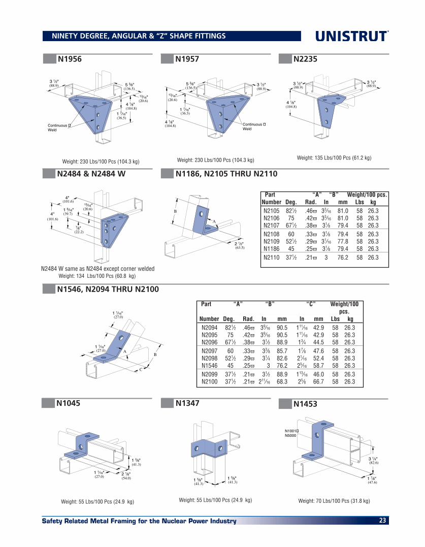
N2484 & N2484 W N1186, N2105 THRU N2110
N1546, N2094 THRU N2100
Weight: 134 Lbs/100 Pcs (60.8 kg)N2484 W same as N2484 except corner welded
(27.0)1 1⁄16"
(27.0)1 1⁄16"
B
C
A
B
(63.5)2 1⁄2"
A
Weight: 230 Lbs/100 Pcs (104.3 kg) Weight: 230 Lbs/100 Pcs (104.3 kg)
(20.6)13⁄16"
(136.5)5 3⁄8"(88.9)
3 1⁄2"
(36.5)1 7⁄16"
4 1⁄8"(104.8)
Continuous Weld
(20.6)13⁄16"
(136.5)5 3⁄8"
(88.9)3 1⁄2"
(36.5)1 7⁄16"
4 1⁄8"(104.8) Continuous
Weld
4 1⁄8"(104.8)
3 1⁄2"(88.9) (88.9)
3 1⁄2"
Weight: 135 Lbs/100 Pcs (61.2 kg)
N1956 N1957 N2235
Weight: 55 Lbs/100 Pcs (24.9 kg) Weight: 55 Lbs/100 Pcs (24.9 kg) Weight: 70 Lbs/100 Pcs (31.8 kg)
(27.0)1 1⁄16"
(54.0)2 1⁄8"
(41.3)1 5⁄8"
(41.3)1 5⁄8"
(41.3)1 5⁄8"
(82.6)3 1⁄4"
(47.6)1 7⁄8"
N1001�N5000
N1045 N1347 N1453
NINETY DEGREE, ANGULAR & “Z” SHAPE FITTINGS
Part “A” “B” Weight/100 pcs. Number Deg. Rad. In mm Lbs kg N2105 821⁄2 .46π 33⁄16 81.0 58 26.3 N2106 75 .42π 33⁄16 81.0 58 26.3 N2107 671⁄2 .38π 31⁄8 79.4 58 26.3 N2108 60 .33π 31⁄8 79.4 58 26.3 N2109 521⁄2 .29π 31⁄16 77.8 58 26.3 N1186 45 .25π 31⁄8 79.4 58 26.3 N2110 371⁄2 .21π 3 76.2 58 26.3
Part “A” “B” “C” Weight/100 pcs. Number Deg. Rad. In mm In mm Lbs kg N2094 821⁄2 .46π 39⁄16 90.5 111⁄16 42.9 58 26.3 N2095 75 .42π 39⁄16 90.5 111⁄16 42.9 58 26.3 N2096 671⁄2 .38π 31⁄2 88.9 13⁄4 44.5 58 26.3 N2097 60 .33π 33⁄8 85.7 17⁄8 47.6 58 26.3 N2098 521⁄2 .29π 31⁄4 82.6 21⁄16 52.4 58 26.3 N1546 45 .25π 3 76.2 25⁄16 58.7 58 26.3 N2099 371⁄2 .21π 31⁄2 88.9 113⁄16 46.0 58 26.3 N2100 371⁄2 .21π 211⁄16 68.3 25⁄8 66.7 58 26.3

Safety Related Metal Framing for the Nuclear Power Industry24
®
(82.6)3 1⁄4"
(136.5)5 3⁄8"
(42.1)1 "21
32
N1001
Weight: 128 Lbs/100 Pcs (58.1 kg)
N1737
7 1⁄4"(184.2)
5 3⁄8"(136.5)3 1⁄2"
(88.9)
(41.3)1 5⁄8"
(136.5)5 3⁄8"
1 "(42.1)
2132
N1377 N1376 A N1376
N1047
N1048 – N1050
Weight: 128 Lbs/100 Pcs (58.1 kg)
Weight: 88 Lbs/100 Pcs (39.9 kg)
Weight: 197 Lbs/100 Pcs (89.4 kg) Weight: 265 Lbs/100 Pcs (120.2 kg)
1 5⁄8"(41.3)
B1 1⁄2"(38.1)
A
Weight: 47 Lbs/100 Pcs (21.3 kg)
Weight: 93 Lbs/100 Pcs (42.2 kg)
Weight: 53 Lbs/100 Pcs (24.0 kg) Weight: 47 Lbs/100 Pcs (21.3 kg)
(27.0)1 1⁄16"
(54.0)2 1⁄8"
(123.8)4 7⁄8"
N1001A3
(34.9)1 3⁄8"
N3000
1 1⁄16"(27.0)
3 3⁄4"(95.3)
1 1⁄16"(27.0) (22.2)
7⁄8"
3 3⁄4"(95.3)
N3300
(20.6)13⁄16"
(27.0)1 1⁄16"
(95.3)3 3⁄4"
N3300
(61.9)2 7⁄16"
N5500
1 1⁄16"(27.0)
3 3⁄4"(95.3)
N2469
N3045 N3345
N5545
N4045
Weight: 67 Lbs/100 Pcs (30.4 kg)
“Z” SHAPE & “U” SHAPE FITTINGS
Part “A” “B” Weight/100 pcs. Number In mm In mm Lbs kg N1048 71⁄4 184.2 41⁄8 104.8 105 47.6 N1049 81⁄2 215.9 53⁄8 136.5 120 54.4 N1050 103⁄8 263.5 71⁄4 184.2 130 59.0

Safety Related Metal Framing for the Nuclear Power Industry 25
Weight: 102 Lbs/100 Pcs (46.3 kg) Weight: 220 Lbs/100 (99.8 kg)
3 3⁄4"(95.3)
3 1⁄2"(88.9)
1"(25.4)
2 Holes �7⁄16" (11.1) Dia.
1 Hole �9⁄16" (14.3) Dia.
3 3⁄4"(95.3)
1 5⁄8"(41.3)
2 Holes �7⁄16" (11.1) Dia.
1 Hole �9⁄16" (14.3) Dia.
1"(25.4) Design Load
1200 Lbs (5.3 kN)
N1834 N1834 A
Requires 3⁄8” x 2-1⁄2” Bolt & Nut (Not Incl.) Requires 3⁄8” x 2-1⁄2” Bolt & Nut (Not Incl.)
Design Load 2500 Lbs (11.1 kN)
5 3⁄8"(136.5)
(42.1)1 "
1 7⁄8"(47.6)
2132
N1383
Weight: 95 Lbs/100 Pcs (43.1 kg)
Weight: 257 Lbs/100 (116.6 kg)
Weight: 197 Lbs/100 Pcs (89.4 kg)
Weight: 209 Lbs/100 Pcs (94.8 kg)
5 3⁄8"(136.5)
3 1⁄2"(88.9)
1 7⁄8"(47.6)
1 "(42.1)
2132
3 1⁄2"(88.9)
5 3⁄8"(136.5) 1 "
(42.1)21
32
3 1⁄2"(88.9) N1001
(47.6)1 7⁄8"
4 7⁄8"(123.8)
N1001A3
1 "(42.1)
(136.5)5 3⁄8"
(34.9)1 3⁄8"
2132
N3000
Weight: 171 Lbs/100 Pcs (77.6 kg)
3 9⁄32"(83.3)
7"(177.8)
3 1⁄2"(88.9)
1 7⁄8"(47.6)
N1001
N2328 N2326 N2329
N2473 N3047
Weight: 84 Lbs/100 Pcs (38.1 kg) Weight: 71 Lbs/100 Pcs (32.2 kg)
Weight: 85 Lbs/100 Pcs (38.6 kg)
3 1⁄2"(88.9)
N3300
N4047
N4376
(136.5)5 3⁄8"
(20.6)13⁄16"
1 "(42.1)
2132
N3300
Weight: 130 Lbs/100 Pcs (59.0 kg) Weight: 176 Lbs/100 Pcs (79.8 kg)
7 1⁄4"(184.2)
N3300��
5 3⁄8"(136.5)
N3300
N4377 N4376 A
“U” SHAPE FITTINGS

Safety Related Metal Framing for the Nuclear Power Industry26
®
Weight: 177 Lbs/100 Pcs (80.3 kg) Weight: 230 Lbs/100 Pcs (104.3 kg)
(47.6)1 7⁄8"
(98.4)3 7⁄8"
1 5⁄8"(41.3)
5 "(137.3)
13 32
(42.1)1 "21 32
(41.3)1 5⁄8"
9 5⁄32"(232.6)
3 7⁄8"(98.4)
(95.3)3 3⁄4"
(42.1)1 "21 32
N2228 N2229
Weight: 193 Lbs/100 Pcs (87.5 kg)Weight: 93 Lbs/100 Pcs (42.2 kg)
Weight: 119 Lbs/100 Pcs (54.0 kg)
Weight: 150 Lbs/100 Pcs (68.0 kg)
(88.9)3 1⁄2"
(95.3)3 3⁄4"
2"(50.8)
(137.3)
1 7⁄8"(47.6)
(41.3)1 5⁄8"
(42.1)1 "21 32
5 "13 32
3 7⁄8"(98.4)
(137.3)
1 7⁄8"(47.6)
(41.3)1 5⁄8"
(42.1)1 "21 32
5 "13 32
(41.3)1 5⁄8"
3 7⁄8"(98.4)
9 5⁄32"(232.6)
(95.3)3 3⁄4"
(42.1)1 "21 32
N2347 N2346 N2345
N2343 R-L
R – As Shown L – Opposite Hand
Weight: 155 Lbs/100 Pcs (70.3 kg)Weight: 115 Lbs/100 Pcs (52.2 kg) Weight: 113 Lbs/100 Pcs (51.3 kg)
2"(50.8)
(47.6)1 7⁄8"
3 7⁄8"(98.4)
1 7⁄8"(47.6)
3 7⁄8"(98.4)
3 3⁄4"(95.3)
2"(50.8)
5 "(137.3)
1 7⁄8"(47.6)
(41.3)1 5⁄8"
(42.1)
13 32
1 "21 32
N2223
N2224 N2227
Weight: 76 Lbs/100 Pcs (34.5 kg)
N2225
Weight: 97 Lbs/100 Pcs (44.0 kg) Weight: 108 Lbs/100 Pcs (49.0 kg)
(62.7)2 "
(161.1)1 7⁄8"(47.6)
15 32
6 "11 32
N5500
2 7⁄16"(61.9)
(136.5)5 3⁄8"
1 "(42.1)
2132
N5500
N5543 N5547
“U” SHAPE & WING FITTINGS

Safety Related Metal Framing for the Nuclear Power Industry 27
Weight: 373 Lbs/100 Pcs (169.2 kg)
Weight: 408 Lbs/100 Pcs (185.1 kg)
1⁄4"(6.4)
3 1⁄2"(88.9)
6"(152.4)
(76.2)3"
(76.2)3"
(152.4)6"
3"(76.2)
3"(76.2)
6"(152.4)
4 Holes�3⁄4" (19.1) Dia.
N2073 A
N2072A & N2072A SQ
6"(152.4)
(76.2)3"
(76.2)3"
(152.4)6"
3"(76.2)
3"(76.2)
6"(152.4)
4 Holes�3⁄4" (19.1) Dia.
1⁄4"(6.4)
3 1⁄2"(88.9)
N1001A (shown)�or N1001
6"�(152.4)
6"�(152.4)
7⁄8"�(22.2)
7⁄8"�(22.2)
7⁄8"�(22.2)
7⁄8"�(22.2)
3"�(76.2)
3"�(76.2)
3"�(76.2)
3"�(76.2)
4 Holes�3⁄4" (19.1) Dia.
N2072A N2072A SQ
N1280
ONE PIECE END CAP
(136.5)5 3⁄8"
3 3⁄4"(95.3)
13⁄16"(20.6)1 1⁄16"
(27.0)
(149.2)5 7⁄8" 1 7⁄8"
(47.6)
13⁄16"(20.6)
13⁄16"(20.6) 30° (.17π)�
Min.
(46.7)1 7⁄8"
1⁄2” x 3” Grade 5 bolt, 1⁄2” nut and 1⁄2” lock washer not included. Order separately.
N2815 NH
Weight: 307 Lbs/100 Pcs (139.3 kg)
N2815 D NH
Weight: 497 Lbs/100 Pcs (225.4 kg)
5 7⁄8"
1 7⁄8"(47.6)
(20.6)13⁄16"
(47.6)1 7⁄8"
13⁄16"
13⁄16"(20.6)
(101.6)4"
(27.0)1 1⁄16"
2 3⁄8"(60.3)
(149.2)
(20.6)
30° (.17π)�Min.
POST BASES, END CAPS & BRACKETS
For use with N1000 Channel
Weight: 11 Lbs/100 Pcs (5.0 kg)
1⁄2” x 3” Grade 5 bolt, 1⁄2” nut and 1⁄2” lock washer not included. Order separately.
Safety Related Metal Framing for the Nuclear Power Industry28
®
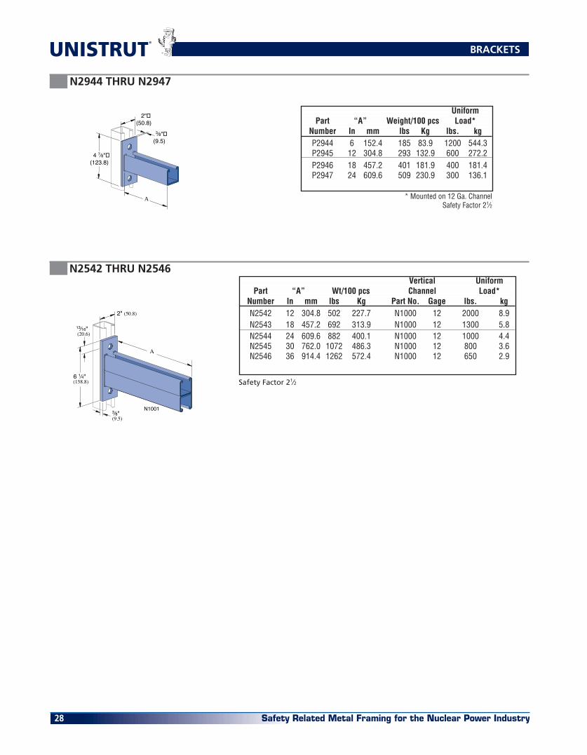
N2542 THRU N2546
3⁄8"(9.5)
13⁄16"(20.6)
6 1⁄4"(158.8)
A
2" (50.8)
N1001
Safety Factor 21⁄2
N2944 THRU N2947
BRACKETS
* Mounted on 12 Ga. ChannelSafety Factor 21⁄2
4 7⁄8"�(123.8)
3⁄8"�(9.5)
A
2"�(50.8)
Uniform Part “A” Weight/100 pcs Load* Number In mm lbs Kg lbs. kg P2944 6 152.4 185 83.9 1200 544.3 P2945 12 304.8 293 132.9 600 272.2 P2946 18 457.2 401 181.9 400 181.4 P2947 24 609.6 509 230.9 300 136.1
Vertical Uniform Part “A” Wt/100 pcs Channel Load* Number In mm lbs Kg Part No. Gage lbs. kg N2542 12 304.8 502 227.7 N1000 12 2000 8.9 N2543 18 457.2 692 313.9 N1000 12 1300 5.8 N2544 24 609.6 882 400.1 N1000 12 1000 4.4 N2545 30 762.0 1072 486.3 N1000 12 800 3.6 N2546 36 914.4 1262 572.4 N1000 12 650 2.9

Safety Related Metal Framing for the Nuclear Power Industry 29
MATERIAL
Unistrut pipe supports, unless noted, are punch-press made from hot-rolled, pickled and oiled steel plates, strip or coil, and conform to ASTM specifications A1011SS, A575, A576, A653, or A36. The fitting steel also meets the physical requirements of ASTM A1011SS GR 33. The pickling of the steel produces a smooth surface free from scale.
Many items are also available in stain-less steel. Consult factory for ordering information.
FINISHES
Pipe supports are available in: electro-galvanized (EG), conforming to ASTM B633 Type III SC1; Hot-dipped galva-nized (HG), conforming to ASTM A123 or A153.
BOLT�SIZEFOOT�LBS.N.m
1⁄4"�206
8
�3⁄8"�1619
25
5⁄8"�11
50
70
1⁄2"�13
100
135
3⁄4"�10125
170
APPLICATION
Unistrut pipe clamps, pipe hangers, brackets and rollers are designed for the support of electrical and mechani-cal services. Supports to meet nearly every requirement can be attained using Unistrut Metal Framing compo-nents.
DIMENSIONS
Imperial dimensions are illustrated in inches. Metric dimensions are shown in parenthesis or as noted. Unless noted, all metric dimensions are in millimeters and rounded to one deci-mal place.
DESIGN BOLT TORQUE
Note: When tightening 1⁄4” screws used with a two piece pipe clamp, a torque of 5 foot pounds (60 inch-
Slotted hex head screw and nut not included.
See chart on page 31 for fasteners.
Finish: Electro-galvanized.(EG)
1 1⁄4"�(31.8)
Design Load
1 1⁄4"(31.8)
Design Load
N1109 NH THRU N1126 NH PIPE CLAMPS FOR RIGID STEEL CONDUIT
N1211 NH THRU N1217 NH UNIVERSAL CLAMPS FOR RIGID OR THINWALL CONDUIT
Thinwall Conduit
STD Pipe or Rigid Conduit
Slotted hex head screw and nut not included.
See chart on page 31 for fasteners.
Finish: Electro-galvanized.(EG)
N1121 NH may also be used with nominal 4” E.M.T.
PIPE CLAMPS
Pipe/Conduit Design Part Size Thickness Wt/100 pcs Load Number In gauge mm lbs Kg lbs kN N1211 NH 1⁄2 16 1.5 10 4.5 400 1.8 N1212 NH 3⁄4 16 1.5 11 5.0 400 1.8 N1213 NH 1 16 1.5 12 5.4 400 1.8 N1214 NH 11⁄4 14 1.9 18 8.2 600 2.7 N1215 NH 11⁄2 14 1.9 20 9.1 600 2.7 N1217 NH 2 14 1.9 22 10.0 600 2.7
Pipe Design Part Size O.D. Size Thickness Wt/100 pcs Load Number In In mm gauge mm lbs Kg lbs kN N1109 NH 3⁄8 .675 17.1 16 1.5 10 4.5 400 1.8 N1111 NH 1⁄2 .840 21.3 16 1.5 11 5.0 400 1.8 N1112 NH 3⁄4 1.050 26.7 14 1.9 15 6.8 600 2.7 N1113 NH 1 1.315 33.4 14 1.9 17 7.7 600 2.7 N1114 NH 11⁄4 1.660 42.2 14 1.9 19 8.6 600 2.7 N1115 NH 11⁄2 1.900 48.3 12 2.7 29 13.2 800 3.6 N1117 NH 2 2.375 60.3 12 2.7 34 15.4 800 3.6 N1118 NH 21⁄2 2.875 73.0 12 2.7 40 18.1 800 3.6 N1119 NH 3 3.500 88.9 12 2.7 47 21.3 800 3.6 N1120 NH 31⁄2 4.000 101.6 11 3.0 62 28.1 1000 4.4 N1121 NH 4 4.500 114.3 11 3.0 67 30.4 1000 4.4 N1123 NH 5 5.563 141.3 11 3.0 80 36.3 1000 4.4 N1124 NH 6 6.625 168.3 10 3.4 102 46.3 1000 4.4 N1126 NH 8 8.625 219.1 10 3.4 130 59.0 1000 4.4
pounds) should be used.
DESIGN LOAD
Design load data, where shown, is based on the ultimate strength of the connection with a safety factor of 5.0, unless otherwise noted.
LOAD
Note: The suffix NH indicates that hardware is not included. Order separately.

Safety Related Metal Framing for the Nuclear Power Industry30
®
1 1⁄4"(31.8)
Design Load
N2024 - N2029 16 ga.N2030 - N2035 14 ga.N2037 - N2044 12 ga.N2059 - N2066 11 ga.N2067 - N2070-84 10 ga.
1 1⁄4"(31.8)
Design Load
Slotted hex head screw and nut not included.
See chart on page 31 for fasteners.
Finish: Electro-galvanized.(EG)
N1425 NH THRU N1431 NH PIPE CLAMPS FOR THIN WALL CONDUIT (E.M.T.)
N2024 NH THRU N2070-84 NH PIPE CLAMPS FOR O.D. TUBING
Slotted hex head screw and nut not included.
See chart on page 31 for fasten-ers.
Finish: Electro-galvanized.(EG)
Pipe Design Part Size O.D. Size Thickness Wt/100 pcs Load Number In In mm gauge mm lbs Kg lbs kN N1425 NH 3⁄8 0.577 14.7 16 1.5 9 4.1 400 1.8 N1426 NH 1⁄2 0.706 17.9 16 1.5 11 5.0 400 1.8 N1427 NH 3⁄4 0.922 23.4 16 1.5 12 5.4 400 1.8 N1428 NH 1 1.163 29.5 14 1.9 15 6.8 600 2.7 N1429 NH 11⁄4 1.510 38.4 14 1.9 18 8.2 600 2.7 N1430 NH 11⁄2 1.740 44.2 12 2.7 29 13.2 800 3.6 N1431 NH 2 2.197 55.8 12 2.7 33 15.0 800 3.6 N1118 NH 21⁄2 2.875 73.0 12 2.7 40 18.1 800 3.6 N1119 NH 3 3.500 88.9 12 2.7 47 21.3 800 3.6 N1120 NH 31⁄2 4.000 101.6 11 3.0 62 28.1 1000 4.4 N1121 NH 4 4.500 114.3 11 3.0 67 30.4 1000 4.4
Pipe Wt/100 Design Part O.D. Size Pcs. Load Number In mm lbs Kg lbs(Kn) N2024 NH 1⁄4 6.4 8 3.6 N2025 NH 3⁄8 9.5 8 3.6 N2026 NH 1⁄2 12.7 9 4.1 400 N2027 NH 5⁄8 15.9 10 4.5 (1.8) N2028 NH 3⁄4 19.1 11 5.0 N2029 NH 7⁄8 22.2 12 5.4 N2030 NH 1 25.4 14 6.4 N2031 NH 11⁄8 28.6 15 6.8 N2032 NH 11⁄4 31.8 16 7.3 600 N2033 NH 13⁄8 34.9 17 7.7 (2.7) N2034 NH 11⁄2 38.1 18 8.2 N2035 NH 15⁄8 41.3 19 8.6 N1430 NH 13⁄4 44.5 29 13.2 N2037 NH 17⁄8 47.6 28 12.7 N2038 NH 2 50.8 31 14.1 N2039 NH 21⁄8 54.0 32 14.5 N2040 NH 21⁄4 57.2 33 15.0 800 N1117 NH 23⁄8 60.3 34 15.4 (3.6) N2042 NH 21⁄2 63.5 35 15.9 N2043 NH 25⁄8 66.7 37 16.8 N2044 NH 23⁄4 69.9 38 17.2 N1118 NH 27⁄8 73.0 40 18.1 N1121 NH 41⁄2 114.3 67 30.4 N2059 NH 45⁄8 117.5 70 31.8 N2060 NH 43⁄4 120.7 72 32.7 1000 N2061 NH 47⁄8 123.8 73 33.1 (4.4) N2062 NH 5 127.0 74 33.6 N2063 NH 51⁄8 130.2 76 34.5 Pipe Wt/100 Design
Part O.D. Size Pcs. Load Number In mm lbs Kg lbs(Kn) N2064 NH 51⁄4 133.4 77 34.9 N2065 NH 53⁄8 136.5 78 35.4 N2066 NH 51⁄2 139.7 79 35.8 N2067 NH 55⁄8 142.9 88 39.9 N2068 NH 53⁄4 146.1 90 40.8 N2069 NH 57⁄8 149.2 92 41.7 N2070 NH 6 152.4 94 42.6 N2070-61 NH 61⁄8 155.6 96 43.5 N2070-62 NH 61⁄4 158.8 98 44.5 N2070-63 NH 63⁄8 161.9 99 44.9 N2070-64 NH 61⁄2 165.1 100 45. N1124 NH 65⁄8 168.3 102 46.3 1000 N2070-66 NH 63⁄4 171.5 104 47.2 (4.4) N2070-67 NH 67⁄8 174.6 106 48.1 N2070-70 NH 7 177.8 108 49.0 N2070-71 NH 71⁄8 181.0 110 49.9 N2070-72 NH 71⁄4 184.2 112 50.8 N2070-73 NH 73⁄8 187.3 114 51.7 N2070-74 NH 71⁄2 190.5 116 52.6 N2070-75 NH 75⁄8 193.7 117 53.1 N2070-76 NH 73⁄4 196.9 119 54.0 N2070-77 NH 77⁄8 200.0 121 54.9 N2070-80 NH 8 203.2 123 55.8 N2070-81 NH 81⁄8 206.4 125 56.7 N2070-82 NH 81⁄4 209.6 126 57.2 N2070-83 NH 83⁄8 212.7 128 58.1 N2070-84 NH 81⁄2 215.9 129 58.5 N1126 NH 85⁄8 219.1 130 59.0
PIPE CLAMPS

Safety Related Metal Framing for the Nuclear Power Industry 31
Hardware sold separately.
See pages 18 - 19, for screws & channel nuts
A ± 1⁄8"
C
Hole Size B
Design Load
1⁄4" X 3⁄4" Round Head �Machine Screw �and Channel Nut �Not Included
FASTENERS FOR UNISTRUT PIPE CLAMPS
N2008 THRU N2020 ONE HOLE CLAMP FOR O.D. TUBING
N2558-05 THRU N2558-60 SINGLE PIECE PIPE STRAP
SupportingRib onN2558-60
See pages 29 - 30
Hardware sold separately.
See pages 18 - 19, for screws & channel nuts
Finish: Electro-galvanized.(EG)
Order NSHS025075EG Separately
Part O.D. Tube Size Thickness Wt/100 pcs Number In mm gauge mm lbs Kg N2008 1⁄4 6.4 16 1.5 4 1.8 N2009 5⁄16 7.9 16 1.5 5 2.3 N2010 3⁄8 9.5 16 1.5 5 2.3 N2012 1⁄2 12.7 16 1.5 6 2.7 N2014 5⁄8 15.9 14 1.9 8 3.6 N2016 3⁄4 19.1 14 1.9 9 4.1 N2018 7⁄8 22.2 14 1.9 10 4.5 N2020 1 25.4 14 1.9 11 5.0
O.D. Tube Size Hex Slotted Machine Screw Hex Nut Pipe Clamp Series Part No. Size (In.) Part No. Size(In.)N1109 NH - N1114 NH NSHS025075EG 1⁄4” x 3⁄4” NHXN025EG 1⁄4”N1115 NH - N1117 NH NSHS031100EG 5⁄16” x 1” NHXN031EG 5⁄16”N1118 NH - N1119 NH NSHS031100EG 5⁄16” x 1” NHXN031EG 5⁄16”N1120 NH - N1126 NH NSHS037125EG 3⁄8” x 1-1⁄4” NHXN037EG 3⁄8”N1211 NH NSHS025100EG 1⁄4” x 1” NHXN025EG 1⁄4”N1212 NH - N1213 NH NSHS025125EG 1⁄4” x 1-1⁄4” NHXN025EG 1⁄4”N1214 NH - N1217 NH NSHS031137EG 5⁄16” x 1-3⁄8” NHXN031EG 5⁄16”N1425 NH - N1429 NH NSHS025075EG 1⁄4” x 3⁄4” NHXN025EG 1⁄4”N1430 NH - N1431 NH NSHS031100EG 5⁄16” x 1” NHXN031EG 5⁄16”N3409 NH - N3413 NH NSHS031100EG 5⁄16” x 1” NHXN031EG 5⁄16”N3414 NH NSHS031125EG 5⁄16” x 1-1⁄4” NHXN031EG 5⁄16”N3515 NH - N3417 NH NSHS031175EG 5⁄16” x 1-3⁄4” NHXN031EG 5⁄16”N2024 NH - N2030 NH NSHS025075EG 1⁄4” x 3⁄4” NHXN025EG 1⁄4”N2031 NH - N2035 NH NSHS025100EG 1⁄4” x 1” NHXN025EG 1⁄4”N2037 NH - N2049 NH NSHS031100EG 5⁄16” x 1” NHXN031EG 5⁄16”N2051 NH - N2070-84 NH NSHS037125EG 3⁄8” x 1-1⁄4” NHXN037EG 3⁄8”
Nominal Design Part Pipe Size “A” “B” “C” Thickness Weight/C Load Number In In mm In mm In mm In (mm) Lbs kg Lbs (kN)N2558-05 1⁄2 27⁄8 73.0 23 10.4N2558-07 3⁄4 31⁄8 79.4 26 11.8N2558-10 1 33⁄8 85.7 9⁄32 7.1 7⁄16 11.1 1⁄8 (3.2) 31 14.1 500 (2.2)N2558-12 11⁄4 33⁄4 95.3 35 15.9N2558-15 11⁄2 37⁄8 98.4 39 17.7N2558-20 2 53⁄4 146.1 94 42.6N2558-25 21⁄2 61⁄4 158.8 114 51.7N2558-30 3 67⁄8 174.6 133 60.3N2558-35 31⁄2 73⁄8 187.3 7⁄16 11.1 11⁄16 17.5 1⁄4 (6.4) 152 68.9 1000 (4.4)N2558-40 4 77⁄8 200.0 176 79.8N2558-50 5 9 228.6 198 89.8N2558-60 6 10 254.0 225 102.1
PIPE CLAMPS

Safety Related Metal Framing for the Nuclear Power Industry32
®
Wt/C 72 Lbs (32.7 kg)
Clamp N2676 provides a means of rod suspension where a free swing of up to 15o (0.8π) is required. Clamp will accommodate 1⁄4” (6.4), 3⁄8” (9.5), or 1⁄2” (12.7) rods. Order swivel nuts N2679-4,-6, or -8 as required. Clamp may also be used with N2677 as illustrated in application drawings on the following page.
Clamp Materials: 1⁄8” (3.2) thick steel.
Rod mount front Rod Size up to 1⁄2"Rod mount rear
Rod Size up to 1⁄2"�Rod Swivel 15° (0.8π)�All Directions
2 Holes 9⁄16" (14.3) Dia.
2 7⁄8"(73.0)
7⁄8"
2 Holes 7⁄16" (11.1) Dia.
(22.2)
2 5⁄8"(66.7)
1⁄2" X 2" Set Screw�and Nut not Included
1⁄8"(3.2) Thick
Swivel Nut and�Jam Nut not�Included
Clamp N2675 is designed for light duty rod suspension. It also may be used with N3016-1024 or N3016-1420 nut as illustrated above for mounting insulators, etc.
Clamp Materials: .105” (2.7) thick steel.Wt/C 33 Lbs (15.0 kg)
Rod Size up to 3⁄8"
N3016-1024, or�N3016-1420 �Channel Nut
Rod Size up to 3⁄8"
2 Holes 9⁄32" (7.1) Dia.
2 1⁄16"(52.4)
5⁄8"
4 Holes 13⁄32" (10.3) Dia.
(15.9)
1 7⁄8"(47.6) 3⁄8" X 1 1⁄2" Set Screw�
and Nut not Included
N2675 NH
N2676 NH
Light Duty
Medium Duty
N1271 NH
Wt/C 95 Lbs (43.1 kg)
3⁄8"(9.5)
7⁄8"(22.2)
1 5⁄8"(41.3)
1 1⁄2"(38.1)
1⁄2" - 13 X 11⁄2" �Set Screw not Included
2 Holes 9⁄16" (14.3) Dia.
Wt/C 91 Lbs (41.3 kg)
N1796 NH
(44.5)1 3⁄4"
7⁄8"(22.2)
1⁄4"(6.4)
3 1⁄2"(88.9)
1⁄2" - 13 X 11⁄2" �Set Screw not Included
3 1⁄2"(88.9)
Order Part No. NCSS050150
For channel height 15⁄8” (41.3).
Design Load250 Lbs (1.1 kN)
Design Load150 Lbs (.7 kN)
Design Load300 Lbs (1.3 kN)
Design Load500 Lbs (2.2 kN)
Design Load Each 500 Lbs (2.2 kN) Use in Pairs Only Design Load Each
480 Lbs (2.1 kN) Use in Pairs Only
BEAM CLAMPS
Note: The suffix NH indicates that hardware is not included. Order separately.

Safety Related Metal Framing for the Nuclear Power Industry 33
N1386
(47.6)1 7⁄8"
(6.4)1⁄4"
(12.7)1⁄2"
Clamp Requires1⁄2" - 13 X 11⁄2" �Hex Head Cap �Screw(NHCS050150)and 1⁄2" Channel �Nut Not Included.
Cap Screw NHCS050150
For use with Channel N1000
For beams between 3⁄4” (19.1) to 15⁄8” (41.3) thick flanges.
For beams under 7⁄8” (22.2) thick flange.
N1648 NH – N1653 NH
N2398 NH, N2401 NH & N2403 NH
Set Screw�Size “C”�not IncludedContinuous�
Weld
7⁄8"(22.2)
2 1⁄2"(63.5)
(63.5)2 1⁄2"
Tapped Hole�Size A
B
D
B
(92.1)3 5⁄8"
3 1⁄4"(82.6)
Set Screw�Size “C” not Included
Tapped�Hole�
Size A D
Continuous�Weld
Part “A” “B” “C” “D” Weight/C Design Load Number In In mm In In mm Lbs kg Lbs kN N1648 NH 1⁄4 - 20 1⁄8 3.2 3⁄8 x 11⁄2 7⁄8 22.2 67 30.4 650 2.9 N1649 NH 5⁄16 - 18 1⁄8 3.2 3⁄8 x 11⁄2 7⁄8 22.2 67 30.4 650 2.9 N1649 A NH 3⁄8 - 16 1⁄8 3.2 3⁄8 x 11⁄2 7⁄8 22.2 67 30.4 650 2.9 N1650 NH 3⁄8 - 16 3⁄16 4.8 1⁄2 x 11⁄2 15⁄16 23.8 100 45.4 1100 4.9 N1650 A NH 1⁄2 - 13 3⁄16 4.8 1⁄2 x 11⁄2 15⁄16 23.8 100 45.4 1100 4.9 N1651 NH 1⁄2 - 13 1⁄4 6.4 1⁄2 x 11⁄2 15⁄16 23.8 130 59.0 1600 7.1 N1651 A NH 5⁄8 - 11 1⁄4 6.4 1⁄2 x 11⁄2 15⁄16 23.8 130 59.0 1600 7.1 N1652 NH 5⁄8 - 11 5⁄16 7.9 5⁄8 x 11⁄2 15⁄16 33.3 160 72.6 2400 10.7 N1653 NH 3⁄4 - 10 5⁄16 7.9 5⁄8 x 11⁄2 15⁄16 33.3 160 72.6 2400 10.7
Part “A” “B” “C” “D” Weight/C Design Load Number In In mm In In mm Lbs kg Lbs kN N2398 NH 1⁄4 - 20 1⁄8 3.2 3⁄8 x 2 121⁄32 42.1 109 49.4 800 3.6 N2401 NH 3⁄8 - 16 3⁄16 4.8 1⁄2 x 2 111⁄16 42.9 156 70.8 1300 5.8 N2403 NH 1⁄2 - 13 1⁄4 6.4 1⁄2 x 2 111⁄16 42.9 201 91.2 1900 8.5
Design Load Each600 Lbs (2.7 kN) Use in Pairs Only
Wt/100 pcs 27 Lbs (12.2 kg)
N1379 NH
(82.6)3 1⁄4"
(25.4)1"
(9.5)3⁄8"
1⁄2" - 13 X 11⁄2" �(NCSS050150)�Set Screw Not Included
Clamp Requires1⁄2" x 13⁄16" �Hex Head Cap Screw�and 1⁄2" Channel �Nut Not Included.
Wt/100 pcs 75 Lbs (34.0 kg)
Cap Screw NHCS050150
For use with Channel N1000
Design Load Each600 Lbs (2.7 kN) Use in Pairs Only
DA
1 1⁄4"(31.8)
N1272 NH & N1985 NH & N1986 NH1⁄2” – 13 x 11⁄2” set screw not included.
Order fasteners separately. Use in pairs.
Design Load Part “A” Flange Thickness Set Screw Weight/C (Use in Pairs Only) Number In mm In mm (not included) Lbs kg Lbs kN N1272 NH 1⁄4 6.4 Up to 3⁄4 Up to 19.1 NCSS037150 39 17.7 450 2.0 N1985 NH 3⁄8 9.5 Up to 3⁄4 Up to 19.1 NCSS050150 62 28.1 1000 4.4 N1986 NH 3⁄8 9.5 7⁄8 to 2 22.2 to 50.8 NCSS050150 74 33.6 900 4.0
BEAM CLAMPS
Note: The suffix NH indicates that hardware is not included. Order separately.

Safety Related Metal Framing for the Nuclear Power Industry34
®
N3380
ʺ2"�(ʺ50.8)1⁄8"
(3.2) 2 7⁄16"(61.9)
1"(25.4)
(60.3)2 3⁄8"
N3703
>2"(>50.8)
Length - 20’
8"(203.2)
Weight: 2775 Lbs/100 Ft (1258.7 kg)
Unistrut N3370 continuous insert is designed to be used in ceilings, walls, or floors. All nuts designed for N3300 (see page 18 - 19) will fit the N3370 insert. Unistrut nuts can be inserted anywhere along the length of the insert providing a means of attaching fittings or rods. The N3370 insert is available in pre-galvanized (PG) or hot-dipped galvanized (HG) finishes.
Nail holes are knockouts to prevent concrete seepage. Anchors on 4” centers.
N3380 end cap used when end distance to first anchor is up to 2”. N3703 end cap anchor is used when end distance to first anchor is over 2”.
Recommended concrete inserts be nailed or anchored to forms every 16 to 24 inches.
Optional closure (I.E. P3712 P) (commercial grade) available to inhibit concrete seepage.
LOAD DATARecommended loading on the N3370 insert in average good con-
crete: N3370 – 1500 lbs. in each foot of length. Minimum safety factor 3.
Concentrated load on the end two inches of the insert should be not more than 750 pounds. Sufficient concrete must surround the insert to conform to design shear stress. The distance between the insert centerline and the concrete edge must be a minimum of 3”.
(Commercial Grade)
N3370 CONTINUOUS INSERT
(22.2)7⁄8"
1 1⁄2"
(60.3)2 3⁄8" (38.1)
1 5⁄8"(41.3)
12 Ga.
(20.6)
(2.7)
13⁄16"
P3712 P
P3712 P
3"(76.2)
>2"(>50.8)
2 7⁄8"(73.0)
N37041"(25.4)
ʺ2"�(ʺ50.8)1⁄8"
(3.2)
N3280
Unistrut N3270 continuous insert is designed to be used in ceilings, walls, or floors. All nuts designed for N3000 (see page 18 - 19) will fit the N3270 insert. Unistrut nuts can be inserted anywhere along the length of the insert providing a means of attaching fittings or rods. The N3270 insert is available in pre-galvanized (PG) or hot-dipped galvanized (HG) finishes.
Nail holes are knockouts to prevent concrete seepage. Anchors on 4” centers.
N3280 end cap used when end distance to first anchor is up to 2”. N3704 end cap anchor is used when end distance to first anchor is over 2”.
Recommended concrete inserts be nailed or anchored to forms every 16 to 24 inches.
Optional closure (I.E. P3712 P) (commercial grade) available to inhibit concrete seepage.
LOAD DATARecommended loading on the N3270 insert in average good con-
crete: N3270 – 2000 lbs. in each foot of length. Minimum safety factor 3.
Concentrated load on the end two inches of the insert should be not more than 1000 pounds. Sufficient concrete must sur-round the insert to conform to design shear stress. The distance between the insert centerline and the concrete edge must be a minimum of 3”.
8"(203.2)
Length - 20’
Weight: 3882 Lbs/100 Ft (1760.8 kg)
(Commercial Grade)
2 7⁄8"(73.0)
1 1⁄2"(38.1)
1 5⁄8"(41.3)
12 Ga.�(2.7)
(20.6)13⁄16"
P3712 P
1 3⁄8"(34.9)
N3270 CONTINUOUS INSERT
P3712 P
CONCRETE INSERTS

Safety Related Metal Framing for the Nuclear Power Industry 35
Wt/C 17 Lbs (7.7 kg)
1 5⁄8"(41.3)
Material: 12 Gage.
Material: 12 Gage.
A
Material: 14 Gage.
N1703, N1704 & END CAP ANCHORSN3704
N2407, SINGLE PIECE END CAPSN3280 & N3380
N3703 END CAP ANCHORS
2 7⁄16"(61.9)
P3300
End cap anchors are designed for use with short pieces of Unistrut Channel to form concrete inserts.
• The N3663 & N4663 cover plate is designed to cover the joint between the inserts when they are butted end to end.
• Material: 16 Gage.
N3663, N4663 JOINT COVERS
Part “A” Wt./100 pcs. Number Channel In mm Lbs kg N1703 N1000 213⁄32 61.1 30 13.6 N1704 N1000 317⁄32 89.7 37 16.8 N3704 N3000 3 76.2 20 9.1
Part Wt./100 pcs. Number Channel Lbs kg N2407 N1000 10 4.5 N3280 N3000 8 3.6 N3380 N3300 5 2.3
Part Wt./100 pcs. Number Channel Lbs kg N3663 N3270 10 4.5 N4663 N3370 6 2.7
CONCRETE INSERTS
Safety Related Metal Framing for the Nuclear Power Industry36
®
P
L
V
M
L
a bP
M
V
M
V
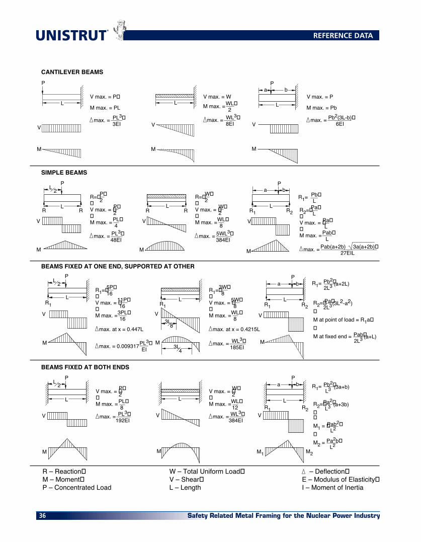
V max. = P�
M max. = PL
max. = PL3�3EI
V max. = W
max. = WL3�8EI
WL�2M max. =
V max. = P
max. = Pb2(3L-b)�6EI
M max. = Pb
M
V
L
PL 2
R R
M
V
LR R
LR1 R2
M
V
a bP
LR1 R2
a bP
V
V
M
M2
LR1 R2
a bP
V
M
L
LR1
PL 2
PL 2
V
M
V
M
L
V
M
L
M1
3L8
3L4
L
R=��V max. = ��M max. =
max. = PL3�48EI
P�2
P�2PL�4
R=��V max. = ��M max. =
max. = 5WL3�384EI
W�2
W�2WL�8
R2=��V max. = ��M max. =
Pb�L
R1=
Pa�L
Pa�L
Pab�L
Pab(a+2b) 3a(a+2b)�27EILmax. =
R2=��M at point of load = R1a��M at fixed end =
Pb2�2L3R1=
Pa�2L3
(a+2L)
(3L2-a2)
Pab�2L3 (a+L)
R2=���M1 = ��M2 =
Pb2�L3R1=
Pa2�L3
(3a+b)
(a+3b)
Pab2�L2
Pa2b�L2
R1=��V max. = ��M max. =
max. at x = 0.447L
5P�16
11P�163PL�16
max. = 0.009317 PL3�EI
V max. = ��M max. =
max. = PL3�192EI
P�2PL�8
V max. = ��M max. =
max. = WL3�384EI
W�2WL�12
R1=��V max. = ��M max. =
max. at x = 0.4215L
3W�8
5W�8
WL�8
max. = WL3�185EI
R1
R – Reaction�M – Moment�P – Concentrated Load
W – Total Uniform Load�V – Shear�L – Length
– Deflection�E – Modulus of Elasticity�I – Moment of Inertia
CANTILEVER BEAMS
SIMPLE BEAMS
BEAMS FIXED AT ONE END, SUPPORTED AT OTHER
BEAMS FIXED AT BOTH ENDS
REFERENCE DATA

Safety Related Metal Framing for the Nuclear Power Industry 37
EXAMPLE IPROBLEM:Determine load and deflectionof a N1000 beam continuous over one support and loaded uniformly on one span.
SOLUTION:A. From load table for N1000 on page 24 load for a 5’-0” span is 680# and deflection is .35”.B. Multiply by factors from Table above. Load = 680# x 1.30 = 884# Deflection = .35” x .92 = .32”
CONVERSION FACTORS FOR BEAMS WITH VARIOUS STATIC LOADING CONDITIONS
All Beam Load tables are for single-span (simple) beams supported at the ends. These can be used in the majority of the cases.
There are times when it is necessary to know what happens with other loading and support conditions. Some common arrangements are shown below. Simply multiply the values from the Beam Load tables by factors given below
Continuous Beam, Two Equal Spans,�Concentrated Load at Center of Each Span
�.67
�.48
DEFLECTION FACTOR
LOAD�FACTOR
LOAD AND SUPPORT CONDITION
SPAN
�1.00
�1.00
�.50
�.25
�1.50
�1.00
�1.00
�.12
�1.30
�.62
�1.10
�1.00
�.80
�2.40
�.30
�.40
�.42
�3.20
�.92
�.71
1. Simple Beam,�Uniform Load
2. Simple Beam,�Concentrated Load at Center
3. Simple Beam,�Two Equal Concentrated Loadcs at 1/4 pts
4. Beam Fixed at Both Ends,�Uniform Load
5. Beam Fixed at Both Ends,�Concentrated Load at Center
6. Cantilever Beam,�Uniform Load
7. Cantilever Beam,�Concentrated Load at End
8. Continuous Beam, Two Equal Spans,�Uniform Load on One Span
9. Continuous Beam, Two Equal Spans,�Uniform Load on Both Ends
10. Continuous Beam, Two Equal Spans,�Concentrated Load at Center of One Span
11.
SPAN SPAN
5' -0" 5' -0"
EXAMPLE IIPROBLEM:Determine load and deflectionof a N5500 cantilever beamwith a concentrated load onthe end.
SOLUTION:A. From load table N5500 on page 57 load for a 3’-0” span is 2190# and deflection is .09”.B. Multiply by factors from Table above. Load = 2190# x .12 = 263# Deflection = .09” x 3.20 = .29”
3' -0"
REFERENCE DATA

Safety Related Metal Framing for the Nuclear Power Industry38
®
b) Pinned Top – Fixed Bottom
The top is restrained against lateral move-ment (translation) but, is allowed to rotate. The bottom is restrained against rotation and lateral movement. This is a common support condition and is used to con-struct the allowable column load applied at the Slot Face tables. “K” equals .80.
c) Pinned Top – Pinned Bottom
Both ends are restrained against lateral movement (translation) but, are allowed to rotate. “K” equals 1.0.
d) Fixed / Free Top – Fixed Bottom
The top is restrained against rotation but is allowed to move laterally. The bottom is restrained against rotation and lateral movement (translation). “K” equals 1.2.
COLUMN LENGTH
The column length is measured from braced point to braced point. A braced point is where the column is restrained from lateral movement (translation) in all directions.
TYPES OF LOADING
a) Concentric Loading Loads applied to the center of gravity
of the column cross-section are con-sidered concentric. A beam that passes over and rests on the top of a column
is an example of concentric loading.
b) Eccentric Loading Any load which is not concentric is ec-
centric. The amount of eccentricity (in inches) has a major effect on the load-carrying capacity of any particular column. A load that is transmitted to a Unistrut Metal Framing column using a standard fitting bolted to the slot face is considered eccentric.
The load tables give allowable loads for both concentric (loaded at C.G.) and certain eccentric (loaded at slot face) load-ing. Allowable loads for other eccentric loading must be determined by a qualified
design professional.
SUPPORT CONDITIONS
Based on the support conditions, an ap-propriate “K” value is selected. This “K” value, which mathematically describes the column end conditions, is used in the column design equations. The most com-mon support condition combinations are as follows:
a) Fixed Top – Fixed Bottom
Both ends are restrained against rotation and lateral movement (translation). K equals .65.
CROSS-SECTIONALSHAPE
The cross-sectional shape of a column member determines the value of it’s “Radius of Gyration” or “r”. In general, a member with a large “r” makes a better column than a member with a small “r”. Each axis of a column has a different “r”. Typically the axis with the smallest “r” determines the final design.
BOLT TORQUE
Bolt torque values are given to ensure the proper connection between Unistrut Metal Framing components. It is impor-tant to understand that there is a direct, but not necessarily consistent, relation-ship between bolt torque and tension in the bolt. Too much tension in the bolt can cause it to break or crush the component parts. Too little tension in the bolt can prevent the connection from developing its full load capacity. The torque values given have been developed over many
years of experience and testing.
These are based on using a properly calibrated torque wrench with a clean dry (non-lubricated) Unistrut fitting, bolt and nut. A lubricated bolt or nut can cause extremely high tension in the connection and may lead to bolt failure. It must be noted that the accuracy of commercial torque wrenches varies widely and it is the responsibility of the installer to ensure that proper bolt torque has been achieved.
Recommended Bolt Torque Bolt 1⁄4” 3⁄8” 1⁄2” 5⁄8” 3⁄4” Size 20 16 13 11 10 Foot 6 19 50 100 125 Lbs. N•m 8 25 70 135 170
REFERENCE DATA

Safety Related Metal Framing for the Nuclear Power Industry 39
AXIAL COLUMN LOADS
Loads based on AISI specifications for the design of Cold-Formed Steel Structural Members (1996 edition).
Loads are not given for KL/R>200.
Section Axial Column Load (Lbs.) Number K= 0.65 K=0.80 K=1.0 K=1.2
N1000 10,750 9,900 8,770 7,730 N1001 25,060 24,620 23,900 23,050 N3000 9,790 9,090 8,190 7,370 N3001 22,670 22,250 21,580 20,780 N3300 7,710 7,190 6,410 5,440 N3301 17,400 16,820 15,900 14,840 N5000 13,050 12,000 11,180 9,590 N5001 30,190 29,820 29,220 28,500 N5500 13,860 12,610 10,910 9,300 N5501 32,840 32,310 31,440 30,410
N1000 8,910 7,730 6,370 5,280 N1001 24,000 23,050 21,570 19,890 N3000 8,300 7,370 6,320 5,440 N3001 21,670 20,780 19,400 17,830 N3300 6,520 5,440 4,030 2,830 N3301 16,020 14,840 13,070 11,190 N5000 11,380 9,590 7,390 5,560 N5001 29,300 28,500 27,220 25,740 N5500 11,120 9,300 7,190 5,550 N5501 31,560 30,410 28,610 26,550
N1000 7,250 5,980 4,660 3,770 N1001 22,590 21,030 18,690 16,170 N3000 7,000 6,010 4,930 4,050 N3001 20,350 18,890 16,710 14,390 N3300 4,960 3,590 2,290 1,590 N3301 14,270 12,450 9,930 7,540 N5000 8,830 6,730 4,700 3,560 N5001 28,100 26,750 24,660 22,320 N5500 8,550 6,580 4,800 3,800 N5501 29,850 27,950 25,070 21,960
N1000 5,890 4,660 3,600 2,940 N1001 20,890 18,690 15,540 12,400 N3000 5,930 4,930 3,860 3,120 N3001 18,760 16,710 13,800 10,920 N3300 3,480 2,290 1,470 KL/r>200
N3301 12,290 9,930 6,970 4,840 N5000 6,580 4,700 3,360 2,620 N5001 26,630 24,660 23,090 19,770 N5500 6,430 4,800 3,610 2,920 N5501 27,780 25,070 21,160 17,200
Section Axial Column Load (Lbs.) Number K= 0.65 K=0.80 K=1.0 K=1.2
N1000 4,800 3,770 2,940 2,380 N1001 18,990 16,170 12,400 8,960 N3000 5,060 4,050 3,120 2,290 N3001 17,000 14,390 10,920 7,810 N3300 2,410 1,590 – –
N3301 10,250 7,540 4,840 3,360 N5000 4,890 3,560 2,620 2,090 N5001 24,930 22,320 19,770 15,800 N5500 4,970 3,800 2,920 2,390 N5501 25,450 21,960 17,200 12,730
N1000 4,010 3,170 2,460 1,970 N1001 16,970 13,640 9,470 6,580 N3000 4,300 3,390 2,430 –
N3001 15,120 12,050 8,270 5,740 N3300 1,770 – – –
N3301 8,260 5,550 3,550 –
N5000 3,860 2,870 2,160 1,750 N5001 23,070 21,110 16,450 12,100 N5500 4,060 3,160 2,460 2,020 N5501 22,950 18,770 13,460 9,350
N1000 3,450 2,730 2,090 1,650 N1001 14,900 11,200 7,250 5,040 N3000 3,690 2,880 1,860 –
N3001 13,210 9,820 6,330 4,400 N3300 – – – –
N3301 6,440 4,250 – –
N5000 3,180 2,410 1,850 1,510 N5001 22,440 18,430 13,300 9,260 N5500 3,450 2,720 2,130 1,740 N5501 20,360 15,660 10,310 7,160
N1000 2,680 2,090 – –
N1001 10,910 7,250 4,640 –
N3000 2,820 1,860 – –
N3001 9,560 6,330 4,050 –
N3300 – – – –
N3301 4,120 – – –
N5000 2,370 1,850 1,450 –
N5001 18,100 13,300 8,540 –
N5500 2,670 2,130 1,660 –
N5501 15,280 10,310 6,600 –
Colu
mn
Uns
uppo
rted
Ht.
– 2
4”Co
lum
n U
nsup
port
ed H
t. –
36”
Colu
mn
Uns
uppo
rted
Ht.
– 4
8”Co
lum
n U
nsup
port
ed H
t. –
60”
Colu
mn
Uns
uppo
rted
Ht.
– 7
2”Co
lum
n U
nsup
port
ed H
t. –
84”
Colu
mn
Uns
uppo
rted
Ht.
– 9
6”Co
lum
n U
nsup
port
ed H
t. –
120
”
REFERENCE DATA

Safety Related Metal Framing for the Nuclear Power Industry40
®
BEAM CLAMPS
Material: † ASTM A575, A576 (Chemicals)/A1011SS [previously A570] , Grade 33 (Physicals) **ASTM A1011SS, Grade 33[previously A570]
N1271 NH † .........................32 N1272 NH † .........................33 N1379 NH † .........................33 N1648 NH ** .......................33 N1649 A NH ** ....................33
N1649 NH ** .......................33 N1650 A NH ** ....................33 N1650 NH ** .......................33 N1651 A NH † ......................33 N1651 NH † .........................33
N1652 NH † .........................33 N1653 NH † .........................33 N1796 NH † .........................32 N1985 NH † .........................33 N1986 NH† ..........................33
BRACKETS
Material: All HG, PL and GR Brackets Conform to ASTM A1011SS, Grade 33[previously A570] (NOTE 2) All PG Brackets Conform to ASTM A653, Grade 33 (NOTE 2)
N2542 .........................28 N2543 .........................28 N2544 .........................28
N2545 .........................28 N2546 .........................28 N2944 .........................28
CHANNEL
Material: All HG Channels Conform to: ASTM A1011SS, Grade 33[previously A570] , All PG Channels Conform to” ASTM A653 Grade 33 N1000 ...........................9
N2398 NH ** .......................33 N2401 NH ** .......................33 N2403 NH * .........................33 N2675 NH ** .......................32 N2676 NH ** .......................32
N2945 .........................28 N2946 .........................28 N2947 .........................28
N1000 HS .........................15 N1000 T .........................15 N1001 ...........................9 N1001 3 ...........................9 N1001 A ...........................9 N1001 A3 ...........................9 N1001 B ...........................9
N1001 B3 ...........................9 N1001 C ...........................9 N1001 C3 ...........................9 N3000 .........................11 N3000 HS .........................15 N3000 T .........................15 N3001 .........................11
N3300 .........................11 N3300 HS .........................15 N3300 T .........................15 N3301 .........................11 N5000 .........................13 N5000 HS .........................15 N5000 T .........................15
N5001 .........................13 N5500 .........................13 N5500 HS .........................15 N5500 T .........................15 N5501 .........................13
CHANNEL NUTS & HARDWARE
Material: As shown for each part number
HSQN025EG ASTM A563, Grade A/ANSI B1822 .....................19 HSQN031EG ASTM A563, Grade A/ANSI B1822 .....................19 HSQN037EG ASTM A563, Grade A/ANSI B1822 .....................19 HSQN050EG ASTM A563, Grade A/ANSI B1822 .....................19 HSQN062EG ASTM A563, Grade A/ANSI B1822 .....................19 N1006-1420 ASTM A1011SS Grade 45 ..................................18 N1008 ASTM A576 Grade 1015 (Modified) ...................18 N1010 ASTM A576 Grade 1015 (Modified) ...................18 N1012 ASTM A675, Grade 60 .......................................18 N1012 S ASTM A675, Grade 60 .......................................18 N1023 ASTM A675, Grade 60 .......................................18 N1023 S ASTM A675, Grade 60 .......................................18 N3006-1420 ASTM A1011SS Grade 45 ..................................18 N3008 ASTM A576, Grade1015 (Modified) ...................18 N3010 ASTM A576, Grade1015 (Modified) ...................18 N4006-1420 ASTM A1011SS Grade 45 ..................................18 N4008 ASTM A576, Grade1015 (Modified) ...................18 N4010 ASTM A576, Grade1015 (Modified) ...................18 N4012 ASTM A36 ..........................................................18 N4023 ASTM A36 ..........................................................18 N5506-1420 ASTM A1011SS Grade 45 ..................................18 N5508 ASTM A576, Grade 1015 (Modified) ..................18 N5510 ASTM A576, Grade 1015 (Modified) ..................18 NCSS037200EG ASTM A29, Grade 1018-1022/ANSI B18.6.2 ......19 NCSS050150EG ASTM A29, Grade 1018-1022/ANSI B18.6.2 ......19 NCSS050200EG ASTM A29, Grade 1018-1022/ANSI B18.6.2 ......19
NFLW025EG ASTM F844/ANSI B18.22.1 ................................19 NFLW037EG ASTM F844/ANSI B18.22.1 ................................19 NFLW050EG ASTM F844/ANSI B18.22.1 ................................19 NHCS050094EG SAE J429, Grade 2/ANSI B18.2.1 .......................19 NHCS050150EG SAE J429, Grade 2/ANSI B18.2.1 .......................19 NHXN025EG ASTM A563, Grade A/ANSI B18.2.2 ...................19 NHXN037EG ASTM A563, Grade A/ANSI B18.2.2 ...................19 NHXN050EG ASTM A563, Grade A/ANSI B18.2.2 ...................19 NLKW025EG ASTM A29, Grade 1055-65/ANSI B18.21.1 (NOTE 3) ............................................................19 NLKW037EG ASTM A29, Grade 1055-65/ANSI B18.21.1 (NOTE 3) ............................................................19 NLKW050EG ASTM A29, Grade 1055-65/ANSI B18.21.1 (NOTE 3) ............................................................19 NSHS025075EG SAE J429, Grade 2/ANSI B18.6.3 .......................19 NSHS025100EG SAE J429, Grade 2/ANSI B18.6.3 .......................19 NSHS025125EG SAE J429, Grade 2/ANSI B18.6.3 .......................19 NSHS031100EG SAE J429, Grade 2/ANSI B18.6.3 .......................19 NSHS031125EG SAE J429, Grade 2/ANSI B18.6.3 .......................19 NSHS031137EG SAE J429, Grade 2/ANSI B18.6.3 .......................19 NSHS031175EG SAE J429, Grade 2/ANSI B18.6.3 .......................19 NSHS037125EG SAE J429, Grade 2/ANSI B18.6.3 .......................19 NTHR025 ASTM A193, Grade B7/ANSI B1.1 ......................19 NTHR037 ASTM A193, Grade B7/ANSI B1.1 ......................19 NTHR050 ASTM A193, Grade B7/ANSI B1.1 ......................19
MATERIAL SPECIFICATIONS AND INDEX
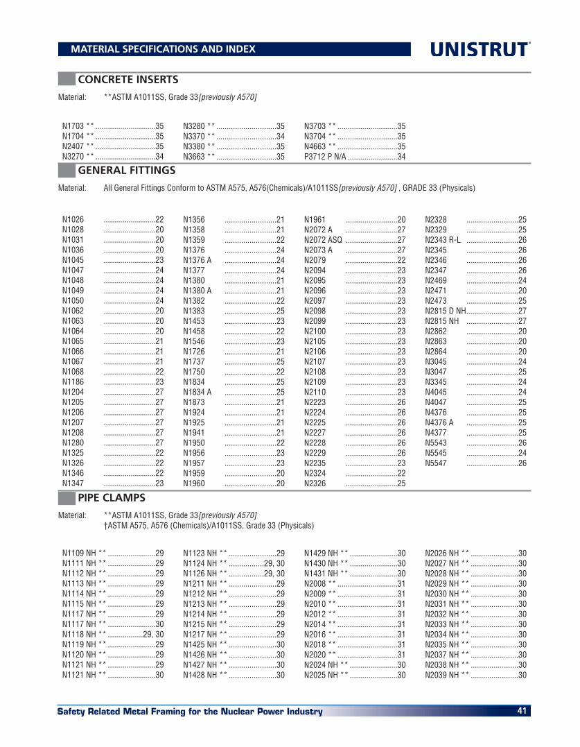
Safety Related Metal Framing for the Nuclear Power Industry 41
CONCRETE INSERTS
Material: **ASTM A1011SS, Grade 33[previously A570]
N1703 ** .............................35 N1704 ** .............................35 N2407 ** .............................35 N3270 ** .............................34
N3280 ** .............................35 N3370 ** .............................34 N3380 ** .............................35 N3663 ** .............................35
N3703 ** .............................35 N3704 ** .............................35 N4663 ** .............................35 P3712 P N/A ........................34
GENERAL FITTINGS
Material: All General Fittings Conform to ASTM A575, A576(Chemicals)/A1011SS[previously A570] , GRADE 33 (Physicals)
N1026 .........................22 N1028 .........................20 N1031 .........................20 N1036 .........................20 N1045 .........................23 N1047 .........................24 N1048 .........................24 N1049 .........................24 N1050 .........................24 N1062 .........................20 N1063 .........................20 N1064 .........................20 N1065 .........................21 N1066 .........................21 N1067 .........................21 N1068 .........................22 N1186 .........................23 N1204 .........................27 N1205 .........................27 N1206 .........................27 N1207 .........................27 N1208 .........................27 N1280 .........................27 N1325 .........................22 N1326 .........................22 N1346 .........................22 N1347 .........................23
N1356 .........................21 N1358 .........................21 N1359 .........................22 N1376 .........................24 N1376 A .........................24 N1377 .........................24 N1380 .........................21 N1380 A .........................21 N1382 .........................22 N1383 .........................25 N1453 .........................23 N1458 .........................22 N1546 .........................23 N1726 .........................21 N1737 .........................25 N1750 .........................22 N1834 .........................25 N1834 A .........................25 N1873 .........................21 N1924 .........................21 N1925 .........................21 N1941 .........................21 N1950 .........................22 N1956 .........................23 N1957 .........................23 N1959 .........................20 N1960 .........................20
N1961 .........................20 N2072 A .........................27 N2072 ASQ .........................27 N2073 A .........................27 N2079 .........................22 N2094 .........................23 N2095 .........................23 N2096 .........................23 N2097 .........................23 N2098 .........................23 N2099 .........................23 N2100 .........................23 N2105 .........................23 N2106 .........................23 N2107 .........................23 N2108 .........................23 N2109 .........................23 N2110 .........................23 N2223 .........................26 N2224 .........................26 N2225 .........................26 N2227 .........................26 N2228 .........................26 N2229 .........................26 N2235 .........................23 N2324 .........................22 N2326 .........................25
N2328 .........................25 N2329 .........................25 N2343 R-L .........................26 N2345 .........................26 N2346 .........................26 N2347 .........................26 N2469 .........................24 N2471 .........................20 N2473 .........................25 N2815 D NH .........................27 N2815 NH .........................27 N2862 .........................20 N2863 .........................20 N2864 .........................20 N3045 .........................24 N3047 .........................25 N3345 .........................24 N4045 .........................24 N4047 .........................25 N4376 .........................25 N4376 A .........................25 N4377 .........................25 N5543 .........................26 N5545 .........................24 N5547 .........................26
PIPE CLAMPS
Material: **ASTM A1011SS, Grade 33[previously A570] † ASTM A575, A576 (Chemicals)/A1011SS, Grade 33 (Physicals)
N1109 NH ** .......................29 N1111 NH ** .......................29 N1112 NH ** .......................29 N1113 NH ** .......................29 N1114 NH ** .......................29 N1115 NH ** .......................29 N1117 NH ** .......................29 N1117 NH ** .......................30 N1118 NH ** .................29, 30 N1119 NH ** .......................29 N1120 NH ** .......................29 N1121 NH ** .......................29 N1121 NH ** .......................30
N1123 NH ** .......................29 N1124 NH ** .................29, 30 N1126 NH ** .................29, 30 N1211 NH ** .......................29 N1212 NH ** .......................29 N1213 NH ** .......................29 N1214 NH ** .......................29 N1215 NH ** .......................29 N1217 NH ** .......................29 N1425 NH ** .......................30 N1426 NH ** .......................30 N1427 NH ** .......................30 N1428 NH ** .......................30
N1429 NH ** .......................30 N1430 NH ** .......................30 N1431 NH ** .......................30 N2008 ** .............................31 N2009 ** .............................31 N2010 ** .............................31 N2012 ** .............................31 N2014 ** .............................31 N2016 ** .............................31 N2018 ** .............................31 N2020 ** .............................31 N2024 NH ** .......................30 N2025 NH ** .......................30
N2026 NH ** .......................30 N2027 NH ** .......................30 N2028 NH ** .......................30 N2029 NH ** .......................30 N2030 NH ** .......................30 N2031 NH ** .......................30 N2032 NH ** .......................30 N2033 NH ** .......................30 N2034 NH ** .......................30 N2035 NH ** .......................30 N2037 NH ** .......................30 N2038 NH ** .......................30 N2039 NH ** .......................30
MATERIAL SPECIFICATIONS AND INDEX

Safety Related Metal Framing for the Nuclear Power Industry42
®
Where not specified, both chemical analysis and physical properties (if applicable) apply to material specifications. Unless otherwise specified the material reference on parts with multiple components pertain to all components.
Note 1: These parts contain sub-components. The material specification for the end plate is ASTM A575, A576 (chemicals) A1011SS, Grade 33 (physicals).
Note 2: These parts contain sub-components. The material specification for the end plate is ASTM A36.
Note 3: The mechanical galvanizing specification for the lock washer is are ASTM B695, Class 5, Type 1.
Note 4: These parts contain sub-components. The material specifications of the sub-components are: Cap Screw SAE J429, Grade 2/ANSI B18.2.1; Hex Nut ASTM A563, Grade A/ANSI B18.2.2; Lock Washer ASTM A29, Grade 1055-65/ANSI B18.21.1
Note 5: ASTM A575, A576 (Chemicals) denotes that parts can be made from either material at the discretion of Unistrut.
Note 6: Unless otherwise specified, products made from ASTM A575/A576 will be grade 1010.
GENERAL NOTES:
PIPE CLAMPS
Material: **ASTM A1011SS, Grade 33[previously A570] † ASTM A575, A576 (Chemicals)/A1011SS[previously A570] , Grade 33 (Physicals)
N2040 NH ** .........................30N2042 NH ** .........................30N2043 NH ** .........................30N2044 NH ** .........................30N2059 NH ** .........................30N2060 NH ** .........................30N2061 NH ** .........................30N2062 NH ** .........................30N2063 NH ** .........................30N2064 NH ** .........................30N2065 NH ** .........................30N2066 NH ** .........................30N2067 NH ** .........................30N2068 NH ** .........................30N2069 NH ** .........................30N2070 NH ** .........................30
N2070-61 NH ** ....................30N2070-62 NH ** ....................30N2070-63 NH ** ....................30N2070-64 NH ** ....................30N2070-66 NH ** ....................30N2070-67 NH ** ....................30N2070-70 NH ** ....................30N2070-71 NH ** ....................30N2070-72 NH ** ....................30N2070-73 NH ** ....................30N2070-74 NH ** ....................30N2070-75 NH ** ....................30N2070-76 NH ** ....................30N2070-77 NH ** ....................30N2070-80 NH ** ....................30N2070-81 NH ** ....................30
N2070-82 NH ** ....................30N2070-83 NH ** ....................30N2070-84 NH ** ....................30N2558-05 ** ..........................31N2558-07 ** ..........................31N2558-10 ** ..........................31N2558-12 ** ..........................31N2558-15 ** ..........................31N2558-20 † ............................31N2558-25 † ............................31N2558-30 † ............................31N2558-35 † ............................31N2558-40 † ............................31N2558-50 † ............................31N2558-60 † ............................31
MATERIAL SPECIFICATIONS AND INDEX

Safety Related Metal Framing for the Nuclear Power Industry 43
DISTRIBUTION SERVICE CENTERS
To serve you directly and dependably, there are over 50 Unistrut distribution service centers located throughout North America. For the nearest Unistrut Service Center, call 1-800-521-7730 or visit our website at www.unistrut.com.
UNISTRUT systems and products are manufactured under one or more of the following United States and Canadian patents and patent applications.
UNITED STATES PATENTS
3,721,463 3,888,441 3,948,012 4,277,923 4,575,295 4,822,199 4,926,592 3,861,107 3,914,063 3,968,624 4,278,228 4,593,514 4,830,531 5,046,291 3,877,275 3,927,499 3,994,111 4,289,415 4,616,799 4,840,525 DES297,668
3,888,440 3,928,930 4,073,114 4,562,681 4,784,552 4,895,331
CANADIAN PATENTS
52,439 596,548 1,007,824 1,130,971 1,245,886 1,263,531 1,320,196 57,636 1,007,823 1,039,948 1,135,925 1,255,069 1,267,265
TRADE NAMES
Publication date June, 2001
UNISTRUT systems and products are sold under many protected trade names including the following:BRITE-LINE, MR STRUT (& DESIGN) N1000, P1000, PERMA GREEN, ROOFWALKS, TELESPAR, TELESTRUT, UNI-CLIP, UNI-CUSHION, UNISTRUT (& DESIGN),UNITED INTERLOCK
UNISTRUT METAL FRAMING

16100 South Lathrop Avenue
Harvey, IL 60426
TOLL-FREE / 800-468-9510
FAX / 708-339-7814
www.unistrut.com
585 Finley Avenue
Ajax, Ontario, L1S 2E4 Canada
PHONE / 905-683-8131
FAX / 905-683-8987
©2017 Atkore International, Inc. All rights reserved. US-L-6001-1701
®