Catalog PA 11 - 2011 - · PDF fileCatalog PA 11 • 2011 Process Automation ... SITRAIN...
116
Components for System Integration Catalog PA 11 • 2011 Process Automation Answers for industry. © Siemens AG, 2010
Transcript of Catalog PA 11 - 2011 - · PDF fileCatalog PA 11 • 2011 Process Automation ... SITRAIN...
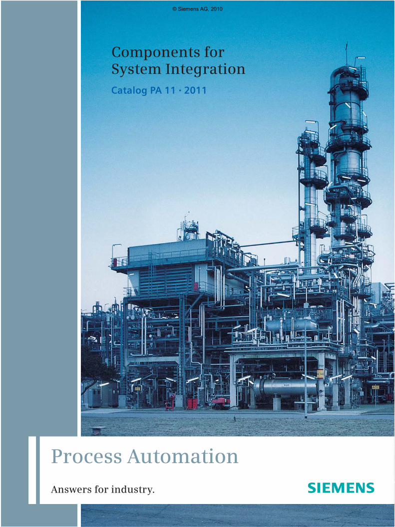
Components for System IntegrationCatalog PA 11 • 2011
Process Automation
Answers for industry.
PA11_2011_EN.indd 2 04.11.2010 08:58:53
© Siemens AG, 2010

* German only
Process Instrumentation, Process Analytics, Weighing Technology Siemens - The One-Stop-Shop
E20001-A810-P710-V2-7600
Field Instruments for Process Automa-tion FI 01
E86060-K6201-A101-B3-7600
Prozess Automation PA 01Process Analytical Instruments
(Nur PDF: E86060-K3501-A101-A6-7600)
SIMATIC NET IK PIIndustrial Communication
E86060-K6710-A101-B6
SITRAIN ITCTraining for Automation and Industrial Solutions
E86060-K6850-A101-C2 *
Catalog CA 01 CA 01Products for Automation and Drives
DVD: E86060-D4001-A510-C9-7600
Industry MallInformation and Ordering Platformin the Internet:
www.siemens.com/industrymall
Related catalogs
© Siemens AG, 2010
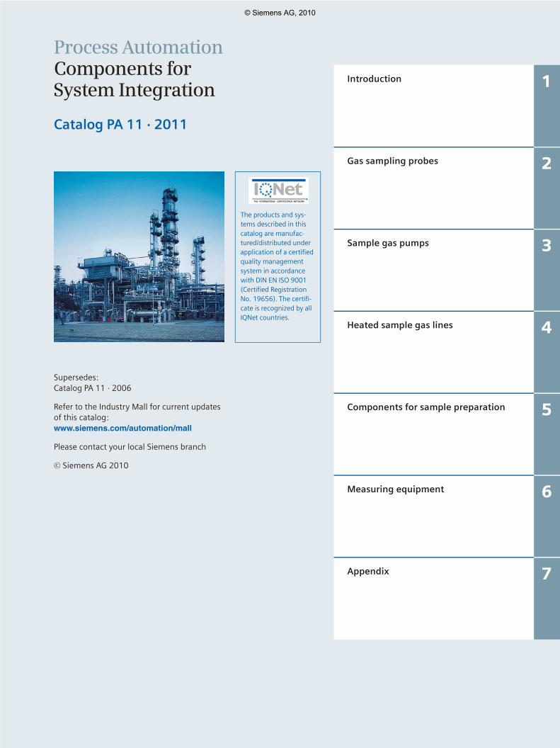
Process AutomationComponents for System Integration
Catalog PA 11 · 2011
Supersedes:Catalog PA 11 · 2006
Refer to the Industry Mall for current updates of this catalog:www.siemens.com/automation/mall
Please contact your local Siemens branch
© Siemens AG 2010
The products and sys-tems described in this catalog are manufac-tured/distributed under application of a certified quality management system in accordance with DIN EN ISO 9001 (Certified Registration No. 19656). The certifi-cate is recognized by all IQNet countries.
Introduction 1
Gas sampling probes 2
Sample gas pumps 3
Heated sample gas lines 4
Components for sample preparation 5
Measuring equipment 6
Appendix 7
© Siemens AG, 2010

1/2 Siemens PA 11 · 2011
© Siemens AG, 2010
1/3Siemens PA 11 · 2011
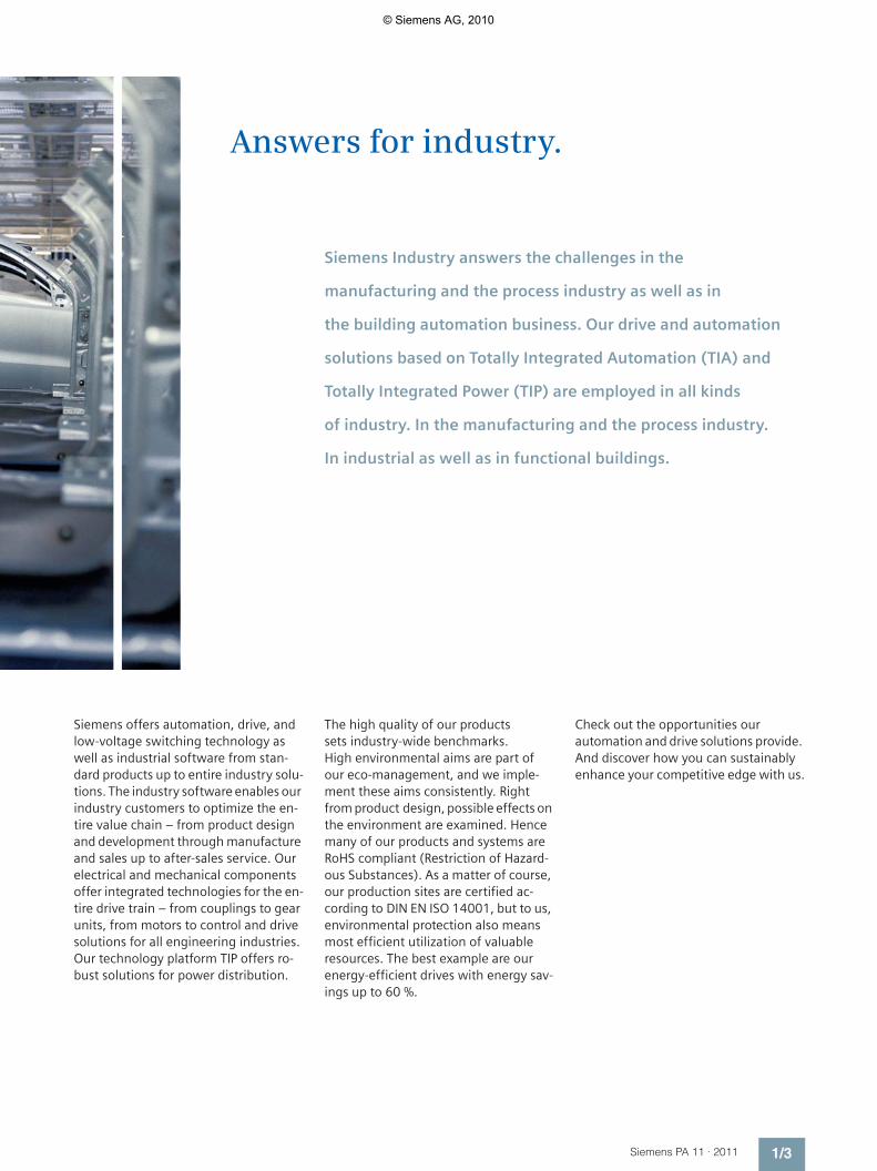
Answers for industry.
Siemens Industry answers the challenges in the
manufacturing and the process industry as well as in
the building automation business. Our drive and automation
solutions based on Totally Integrated Automation (TIA) and
Totally Integrated Power (TIP) are employed in all kinds
of industry. In the manufacturing and the process industry.
In industrial as well as in functional buildings.
Siemens offers automation, drive, and low-voltage switching technology as well as industrial software from stan-dard products up to entire industry solu-tions. The industry software enables our industry customers to optimize the en-tire value chain – from product design and development through manufacture and sales up to after-sales service. Our electrical and mechanical components offer integrated technologies for the en-tire drive train – from couplings to gear units, from motors to control and drive solutions for all engineering industries. Our technology platform TIP offers ro-bust solutions for power distribution.
The high quality of our products sets industry-wide benchmarks. High environmental aims are part of our eco-management, and we imple-ment these aims consistently. Right from product design, possible effects on the environment are examined. Hence many of our products and systems are RoHS compliant (Restriction of Hazard-ous Substances). As a matter of course, our production sites are certified ac-cording to DIN EN ISO 14001, but to us, environmental protection also means most efficient utilization of valuable resources. The best example are our energy-efficient drives with energy sav-ings up to 60 %.
Check out the opportunities our automation and drive solutions provide. And discover how you can sustainably enhance your competitive edge with us.
© Siemens AG, 2010
1/4 Siemens PA 11 · 2011
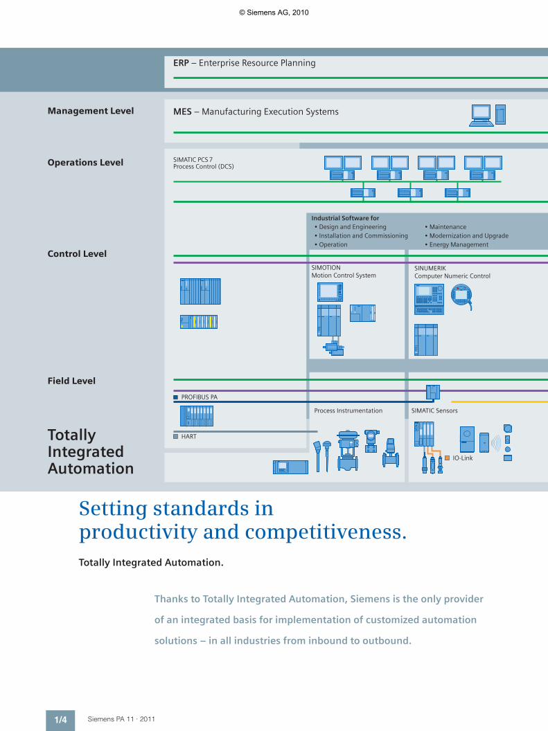
Field Level
Control Level
Operations Level
Management Level
ERP – Enterprise Resource Planning
MES – Manufacturing Execution Systems
SIMATIC PCS 7Process Control (DCS)
• Maintenance• Modernization and Upgrade• Energy Management
Industrial Software for• Design and Engineering• Installation and Commissioning• Operation
Process Instrumentation SIMATIC Sensors
SINUMERIK Computer Numeric Control
SIMOTIONMotion Control System
IO-Link
HART
PROFIBUS PA
Totally IntegratedAutomation
Setting standards in productivity and competitiveness.Totally Integrated Automation.
Thanks to Totally Integrated Automation, Siemens is the only provider
of an integrated basis for implementation of customized automation
solutions – in all industries from inbound to outbound.
© Siemens AG, 2010
1/5Siemens PA 11 · 2011
SIMATIC WinCC SCADA System
SIMATIC NETIndustrial Communi-cation
SIMATIC ControllersModular/Embedded/PC-based
SIMATIC HMIHuman Machine Interface
Safety Integrated
Low-Voltage Controlsand Distribution
SIMATIC Distributed I/O SINAMICS Drive Systems
KNX GAMMA instabus
PROFIBUSPROFIsafe
PROFIsafe Industrial Ethernet
PROFINET
AS-Interface
Industrial Ethernet
Ethernet
Industrial Ethernet
Ethernet
Totally Integrated Power
ASIsafe
SIMATIC IT
02
.03
.20
09
TIA is characterized by its unique continuity.
It provides maximum transparency at all levels with reduced interfacing re-quirements – covering the field level, production control level, up to the cor-porate management level. With TIA you also profit throughout the complete life cycle of your plant – starting with the initial planning steps through oper-ation up to modernization, where we offer a high measure of investment se-curity resulting from continuity in the further development of our products and from reducing the number of inter-faces to a minimum.
The unique continuity is already a defined characteristic at the development stage of our products and systems.
The result: maximum interoperability – covering the controller, HMI, drives, up to the process control system. This re-duces the complexity of the automation solution in your plant. You will experi-ence this, for example, in the engineer-ing phase of the automation solution in the form of reduced time requirements and cost, or during operation using the continuous diagnostics facilities of To-tally Integrated Automation for increas-ing the availability of your plant.
© Siemens AG, 2010
1/6 Siemens PA 11 · 2011
Integrated power distribution from one source.Totally Integrated Power.
© Siemens AG, 2010

1/7Siemens PA 11 · 2011
Products and systemsMedium voltage Transformers Low voltage Installation
technologyBuildingautomation
Communication
Processes /industrial automation
Industrial Ethernet
Planning and system configuration
≤ 110 kV
IEC 61850
PROFIBUS
PROFINET
KNX EIB
BACnet
03.0
4.20
08
Electrical power distribution in buildings requires integrated solutions. Our response: Totally Integrated Power. This means innovative and integrated, interface-optimized products and systems which have been optimally coordinated and complemented with communication and software modules that link power distribution to building automation or industrial automation. Totally Integrated Power accompanies power distribution projects from one end to the other. From A to Z. From the planning to the building’s use: Totally Integrated Power offers signifi-cant advantages in every project stage and to everyone involved in the project – the investors, electrical plan-ning engineers, electricians, users and building facility managers.
Our portfolio comprises everything from engineering tools to the matching hardware: from switchgear and distribution systems for medium volt-age to transformers, from switching and circuit-protection devices to low-voltage switchgear and busbar trunking systems, as far as to the small distribution board and the wall outlet. It goes without saying that both the medium-voltage switchgear, which requires no maintenance, and the low-voltage switchgear are type-tested, and their busbar connections, too. Comprehensive protection systems ensure the safety of man and machine at any time.
© Siemens AG, 2010

1/8 Siemens PA 11 · 2011
Chemical
Pharmaceutical
Water/wastewater
Mining, aggregates,cement
Oil and gas/hydrocarbonprocessing
Pulp and paper
Food and beverage
Marine
IndustriesIn the field of process instrumentation, process analytics and weighing
technology, Siemens focuses on a number of key industries such as:
© Siemens AG, 2010
1/9Siemens PA 11 · 2011
Siemens is a leading provider of process
analyzers and process analysis systems.
We offer our global customers the best
solutions for their applications based
on innovative analysis technologies,
customized system engineering, sound
knowledge of customer applications and
professional support.
And with Totally Integrated Automation,
Siemens Process Analytics is your qualified
partner for efficient solutions that integrate
process analyzers into automation systems
in the process industry.
Process Analytics
© Siemens AG, 2010

1/10 Siemens PA 11 · 2011
Gas Analyzers
ULTRAMAT 23
CALOMAT 6 in field housing
SERIES 6
The Series 6 gas analyzers are comprehen-sive analyzers that meet the full range ofrequirements:
CALOMAT 6
The CALOMAT 6 19” rack mount or as afield device uses the thermal conductivitymethod to accurately measure the compo-sition and concentration of process gases.It is primarily designed for the measure-ment of hydrogen in inert gas concen-trations in blast furnace gas and carbondioxide mixtures.
CALOMAT 62
The CALOMAT 62 applies thermal conduc-tivity detection (TCD) principles and isspecially designed for use in applicationswith corrosive gases such as chlorine. TheCALOMAT 62 measures the concentrationof gas components such as H2, Cl2, HCL orNH3 in binary or quasi-binary gas blends.
The technology used in state-of-the-artprocess analyzers is determined by theneeds of the specific application. Devicesmust be cost-effective, functional, spaceand energy-saving, and must provide justthe right amount of power to meet allneeds.
Siemens Process Analytics offers a wideand innovative portfolio designed to meetall user requirements for comprehensiveproducts and solutions.
We combine outstanding expertise in de-veloping high-performance analyticaldevices with in-depth application knowl-edge from many process industry applica-tions.
The analyzers operate using a menustructure and in accordance with NAMURrecommendations. The analyzers areeasily integrated into the SIMATIC TotallyIntegrated Automation concept and areprogrammed using SIMATIC PDM softwareand PROFIBUS DP and PA interfaces.
PROCESS GAS ANALYSIS – EXTRACTIVE
ULTRAMAT 23
The ULTRAMAT 23 is a cost-effective multi-component analyzer for the measurementof up to 3 infrared sensitive gases usingthe NDIR principle plus O2 using an electro-chemical oxygen measuring cell.
The ULTRAMAT 23 is suitable for a widerange of standard applications, such asemission monitoring, furnace optimiza-tion, room air monitoring and other appli-cations. Calibration using ambient aireliminates the need to use calibrationgases.
From emission monitoring in waste incinerators and power plants to gas analysisin the chemical industry to rotary kiln monitoring in cement plants, the highlyaccurate and reliable Siemens analyzers will always do the job.
CALOMAT 6/62
© Siemens AG, 2010

1/11Siemens PA 11 · 2011
Series 6 in field housing for usein hazardous areas
OXYMAT 6/61/64
ULTRAMAT 6
ULTRAMAT/OXYMAT 6
ULTRAMAT 6
The ULTRAMAT 6 is an analyzer in 19” rackmount or field housing. Measurement ofup to four infrared active components in asingle unit is possible. It can be used in allapplications from emission measurementto process control, even in the presence ofhighly corrosive gases.
ULTRAMAT/OXYMAT 6
The Series 6 units can be combined in a19” rack to form multi-component deviceswith ULTRAMAT 6 and OXYMAT 6 benches.This provides, with the smallest possiblefootprint, an infrared channel for the mea-surement of up to two IR components anda channel for oxygen measurement.
FIDAMAT 6
The FIDAMAT 6 measures the total hydro-carbon content in air or even in high-boiling gas mixtures. It covers nearly allrequirements, from the detection of tracehydrocarbon in pure gas analyses to totalmeasurement of high hydrocarbon concen-trations, even in the presence of corrosivegases.
Ex-proof designs
An additional purge monitoring unit makesthe CALOMAT 6, OXYMAT 6 and ULTRAMAT 6gas analyzers in field housing suitable forinstallation in hazardous areas. Measure-ments can include both non-flammableand flammable gases.
OXYMAT 6
The OXYMAT 6 is an oxygen analyzer, optio-nally in 19” rack mount or in a robust fieldhousing for installation in harsh environ-ments. The OXYMAT 6 can be used in appli-cations including emission measurementsto use in production process control andquality assurance. Due to its ultrafast re-sponse, the OXYMAT 6 is perfect for moni-toring safety-relevant plants. Its corrosion-proof design also makes the OXYMAT 6the analyzer of choice for analysis in thepresence of highly corrosive gases.
OXYMAT 61
The OXYMAT 61 is a low-cost oxygenanalyzer for standard applications. It canuse ambient air as a reference gas thatis supplied to the analyzer section by theintegral pump.
OXYMAT 64
The OXYMAT 64 is a gas analyzer for themeasurement of smallest oxygen con-centrations in pure gas applications. Airseparation plants, production of technicalgases, welding in a protective atmosphere –these are just a few examples where theOXYMAT 64, a completion of the well-pro-ven Siemens Series 6 of continuous gasanalyzers, reliably detects small traces ofoxygen.
FIDAMAT 6
© Siemens AG, 2010

1/12 Siemens PA 11 · 2011
Gas Analyzers
SITRANS SL
ANALYTICAL APPLICATION SETS
FLK gas sample probe
A specially designed extraction probefor cement rotary kilns with liquid to aircooling. The probe is cooled by means ofa special cooling liquid which permits gastemperatures up to 200°C (392°F) andtherefore lies above the acid dew pointof the flue gas. Buildup of condensedproducts and downtime due to frequentmaintenance are prevented.
SERVICE AND MAINTENANCE
SIPROM GA
The SIPROM GA software tool is designedfor service and maintenance applicationswith all process gas analyzers. SIPROM GAcan control and monitor all functions ofthe analyzers as independent or networkedunits. Integration into the Ethernet permitsremote servicing and diagnostics over longdistances.
PROCESS GAS ANALYSIS – IN-SITU
LDS 6
The robust and reliable LDS 6 in-situ gasanalyzer can measure gases even underextreme conditions. Precise and reliableresults are obtained even at 1,500°C(2,732°F) or where the dust concentrationis very high. The LDS 6, for example, mea-sures in-situ concentrations of O2 (Temp.),NH3, HCl, HF H2O, CO or CO2 in flue gasbefore and after gas cleaning. Applicationsin the chemical and petrochemical indus-tries, for steel and metal production, as wellas in cement or paper plants are a matchfor the LDS 6.
SITRANS SL
SITRANS SL sets a new benchmark with in-situ technology for process control – evenunder extreme measuring conditions. Itoffers proven technology integrated into amore compact in-situ gas analyzer design.
SITRANS SL combines the benefits of theproven referencing technology – with adirect operating mode as close as possibleto the process. An integrated reference cell,filled with a non-interfering gas, whichallows laser locking completely indepen-dent of process gas concentrations leadsto utmost stable operation, negligible driftvalues and extended maintenance inter-vals. SITRANS SL designed in a unique andcompact design, including a local user inter-face (LUI) is the perfect solution for singlepoint measurement applications in roughenvironments.
SITRANS SL is used for process control in thechemical industry, even in hazardous areasdue to its EEx d design. Other applicationsare e.g. process optimization in the steelindustry or combustion control in boilersor waste incinerators.
FLK Gas Sample Probe
LDS 6
© Siemens AG, 2010
1/13Siemens PA 11 · 2011
SITRANS CV
MAXUM edition II
MicroSAM
MAXUM edition II
is very well suited to use in rough indus-trial environments and performs a widerange of duties in the chemical and petro-chemical industries and in refineries.A selection of columns and detectors per-mits highly selective and sensitive analysisof multiple process components.
Benefits of MAXUM edition II:
Flexible oven concept, temperature-programmable and energy-saving singleor dual oven configurations.Valveless live sample injection andcolumn switching.Parallel chromatography allows divisionof a single-train chromatograph analysisinto multiple single trains.Open network with TCP/IP and Ethernetfor communication with PCs, otherchromatographs or a DCS.
MicroSAM
is the smallest explosion-proof in-line pro-cess gas chromatograph made by Siemens.State-of-the-art silicon-based microme-chanical components allow miniaturizationand increased performance at the sametime. And MicroSAM is so easy to use andso rugged and small that it can be mount-ed right at the sampling point.Its performance profile is impressive:
State-of-the-art technology drasticallyreduces cycle times, providing betterinformation about the process.Valveless live sample injection andcolumn switching.Multiple detection for verification of theresults.Synchronicity: multiple analyzers can beconnected in parallel for several samplestreams, resulting in more informationper time unit, a high degree of reliabilityshould one of the systems fail, and easyimplementation of redundant systems.Cost-effective and compact, savinginstallation, maintenance, and servicecosts.
SITRANS CV
A gas chromatograph for reliable, exactand fast analysis of natural gas. Therugged and compact design makes theSITRANS CV suitable for extreme areas ofuse, e.g. off-shore exploration or directmounting on a pipeline. Operation ofSITRANS CV using CV Control software issimple, clear and fast. The Software“CV Control“ has been specially developedfor the requirements of the natural gasmarket, e.g. custody transfer.
Process Gas ChromatographsSiemens application experience and innovative technology in the field of processgas chromatography helps us provide exceptional customer solutions. Small, com-pact, powerful, and cost-effective, MicroSAM is capable of performing accuratemeasuring tasks in virtually all industrial sectors.
© Siemens AG, 2010
1/14 Siemens PA 11 · 2011
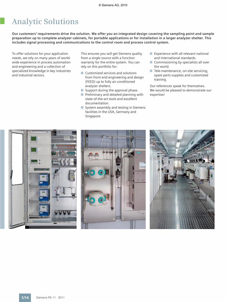
Analytic Solutions
To offer solutions for your applicationneeds, we rely on many years of world-wide experience in process automationand engineering and a collection ofspecialized knowledge in key industriesand industrial sectors.
This ensures you will get Siemens qualityfrom a single source with a functionwarranty for the entire system. You canrely on this portfolio for:
Customized services and solutionsfrom front-end engineering and design(FEED) up to fully air-conditionedanalyzer shelters.Support during the approval phase.Preliminary and detailed planning withstate-of-the-art tools and excellentdocumentation.System assembly and testing in Siemensfacilities in the USA, Germany andSingapore.
Our customers’ requirements drive the solution. We offer you an integrated design covering the sampling point and samplepreparation up to complete analyzer cabinets, for portable applications or for installation in a larger analyzer shelter. Thisincludes signal processing and communications to the control room and process control system.
Experience with all relevant nationaland international standards.Commissioning by specialists all overthe world.Tele-maintenance, on-site servicing,spare parts supplies and customizedtraining.
Our references speak for themselves.We would be pleased to demonstrate ourexpertise!
© Siemens AG, 2010

Siemens PA 11 · 2011
22/2 Gas sampling probe for process gas
lines, without filter
2/3 Gas sampling probe with external, electrically heated filter
2/3 Self-regulating2/4 With temperature controller2/5 With self-regulating heater,
explosion-proof version according to ATEX2/6 With temperature monitoring and
connection for backflushing
2/7 Accessories and configuration example
Gas sampling probes
© Siemens AG, 2010
Gas sampling probesGas sampling probe for process gas lines, without filter
2/2 Siemens PA 11 · 2011
2
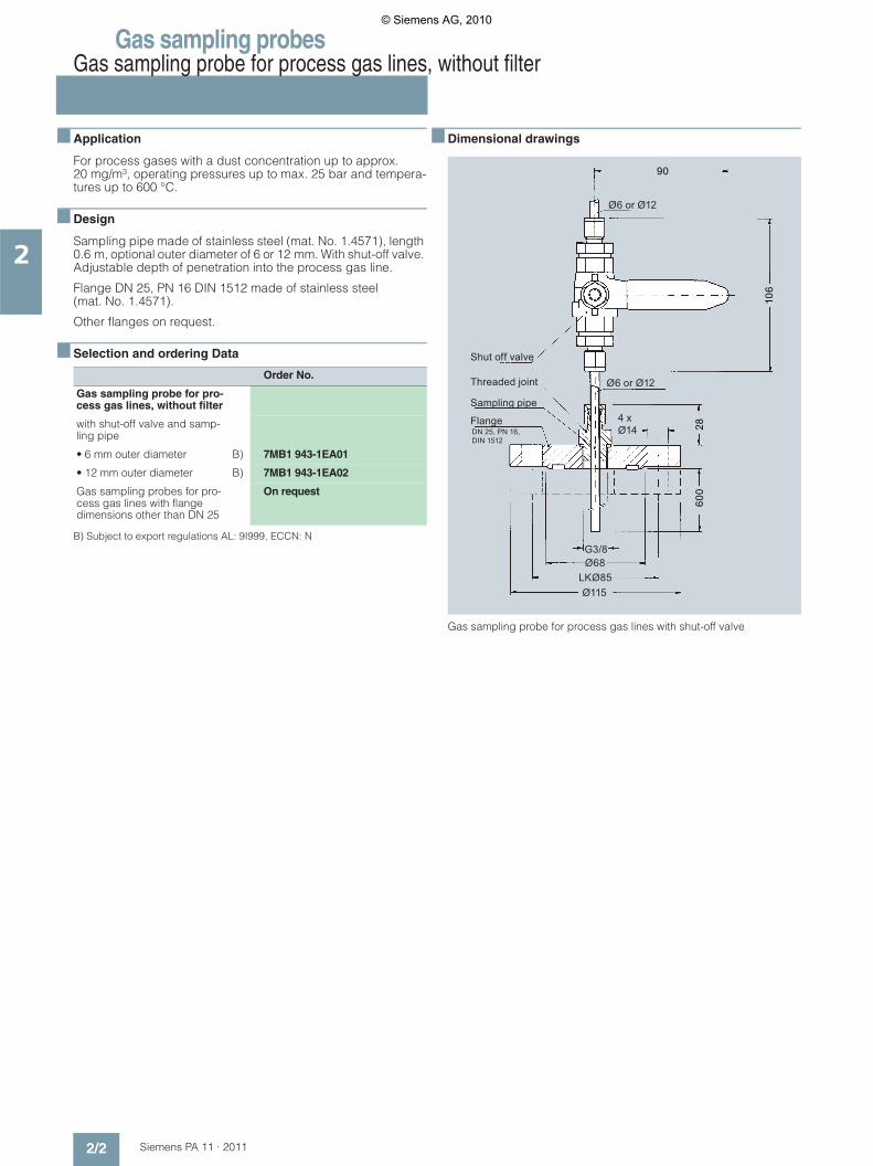
■ Application
For process gases with a dust concentration up to approx. 20 mg/m³, operating pressures up to max. 25 bar and tempera-tures up to 600 °C.
■ Design
Sampling pipe made of stainless steel (mat. No. 1.4571), length 0.6 m, optional outer diameter of 6 or 12 mm. With shut-off valve. Adjustable depth of penetration into the process gas line.
Flange DN 25, PN 16 DIN 1512 made of stainless steel (mat. No. 1.4571).
Other flanges on request.
■ Selection and ordering Data
B) Subject to export regulations AL: 9I999, ECCN: N
■ Dimensional drawings
Gas sampling probe for process gas lines with shut-off valve
Order No.
Gas sampling probe for pro-cess gas lines, without filter
with shut-off valve and samp-ling pipe
• 6 mm outer diameter B) 7MB1 943-1EA01
• 12 mm outer diameter B) 7MB1 943-1EA02
Gas sampling probes for pro-cess gas lines with flange dimensions other than DN 25
On request
Ø6 or Ø12
Ø6 or Ø12
4 xØ14
Shut off valve
Threaded joint
Sampling pipe
Flange
G3/8Ø68
Ø115LKØ85
DN 25, PN 16,DIN 1512
106
2860
0
90
© Siemens AG, 2010

Gas sampling probesGas sampling probe with external, electrically heated filter
Self-regulating
2/3Siemens PA 11 · 2011
2
■ Application
For continuous gas sampling in processes with dust loads < 2 g/m³ and an operating pressure up to 6 bar.
■ Design
A filter chamber heated at 180 °C contains a filter element. Self-regulating heating elements are used. A temperature controller and limiter are not required.
The parts in contact with the sample gas are made of stainless steel (mat. No. 1.4571), Viton and ceramics.
■ Technical specifications
■ Selection and ordering Data
B) Subject to export regulations AL: 9I999, ECCN: N
The filter element, the screwed gland for connection of the sam-ple gas line, and the sampling tube must be ordered separately. Also refer to the configuration example under "Accessories and configuration example".
■ Dimensional drawings
Gas sampling probe with external, electrically heated filter without weatherproof cover
Operating pressure Max. 6 bar
Operating temperature 180 °C at ambient temperature 0 ... 80 °C
Material of filter enclosure and flange
Stainless steel (mat. no. 1.4571)
Mounting flange DN 65, PN 6, form B
Connection of sample gas outlet Female thread ¼ NPT
Electric connection 2 plug-in connectors
Degree of protection according to EN 60 529
IP54
Power supply 110 … 240 V AC, 50/60 Hz
Power consumption Approx. 400 VA
Weight Approx. 9 kg
Order No.
Gas sampling probe B) 7MB1 943-2FA00
With self-regulating heating elements, with undertempera-ture alarm, heated, 115 … 230 V AC, 50/60 Hz, 400 VAComplete thermal insulation with protective sleeve, without weather protection hood
Filter element (order separately)
Sample gas outletNPT 1/4“
Male coupling (order separately)
108Ø50
SW36
G3/4
254Ø160Ø130
Ø14
NETZ NETZ
ALARM-AUSGANG
ALARM-AUSGANG
ALARMOUTPUT
ALARMOUTPUT
POWER POWER
177
55
© Siemens AG, 2010
Gas sampling probesGas sampling probe with external, electrically heated filter
With temperature controller
2/4 Siemens PA 11 · 2011
2
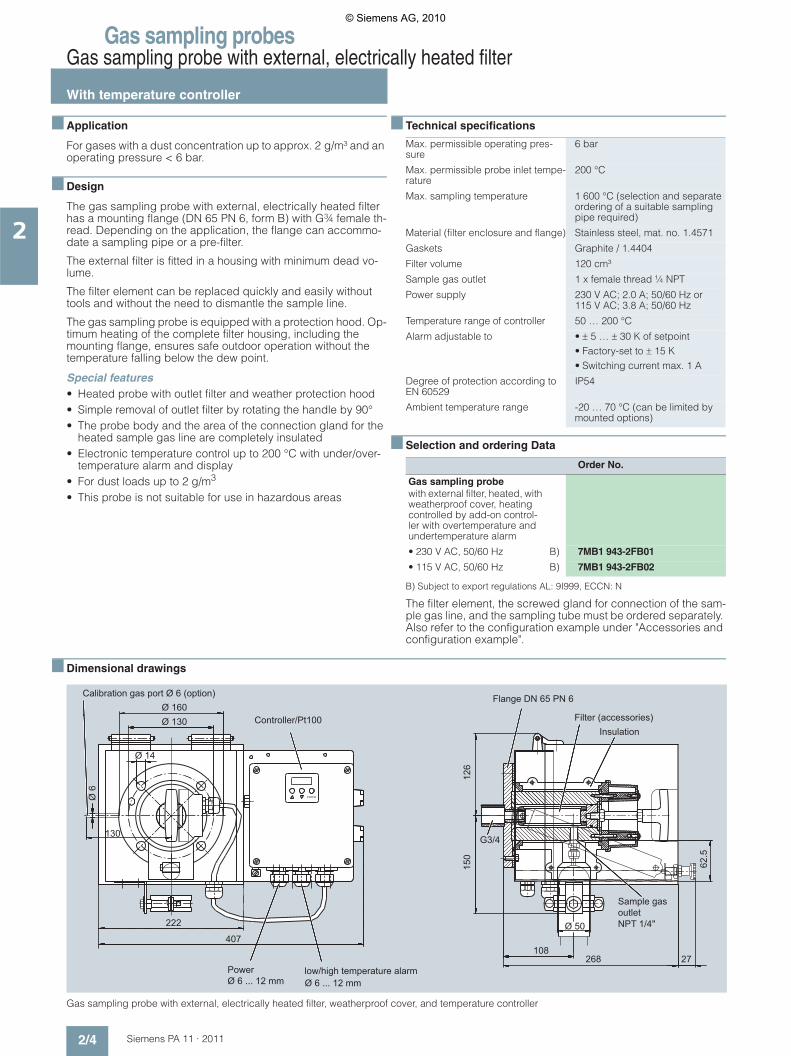
■ Application
For gases with a dust concentration up to approx. 2 g/m³ and an operating pressure < 6 bar.
■ Design
The gas sampling probe with external, electrically heated filter has a mounting flange (DN 65 PN 6, form B) with G¾ female th-read. Depending on the application, the flange can accommo-date a sampling pipe or a pre-filter.
The external filter is fitted in a housing with minimum dead vo-lume.
The filter element can be replaced quickly and easily without tools and without the need to dismantle the sample line.
The gas sampling probe is equipped with a protection hood. Op-timum heating of the complete filter housing, including the mounting flange, ensures safe outdoor operation without the temperature falling below the dew point.
Special features• Heated probe with outlet filter and weather protection hood• Simple removal of outlet filter by rotating the handle by 90°• The probe body and the area of the connection gland for the
heated sample gas line are completely insulated• Electronic temperature control up to 200 °C with under/over-
temperature alarm and display• For dust loads up to 2 g/m3
• This probe is not suitable for use in hazardous areas
■ Technical specifications
■ Selection and ordering Data
B) Subject to export regulations AL: 9I999, ECCN: N
The filter element, the screwed gland for connection of the sam-ple gas line, and the sampling tube must be ordered separately. Also refer to the configuration example under "Accessories and configuration example".
■ Dimensional drawings
Gas sampling probe with external, electrically heated filter, weatherproof cover, and temperature controller
Max. permissible operating pres-sure
6 bar
Max. permissible probe inlet tempe-rature
200 °C
Max. sampling temperature 1 600 °C (selection and separate ordering of a suitable sampling pipe required)
Material (filter enclosure and flange) Stainless steel, mat. no. 1.4571
Gaskets Graphite / 1.4404
Filter volume 120 cm³
Sample gas outlet 1 x female thread ¼ NPT
Power supply 230 V AC; 2.0 A; 50/60 Hz or 115 V AC; 3.8 A; 50/60 Hz
Temperature range of controller 50 … 200 °C
Alarm adjustable to • ± 5 … ± 30 K of setpoint• Factory-set to ± 15 K• Switching current max. 1 A
Degree of protection according to EN 60529
IP54
Ambient temperature range -20 … 70 °C (can be limited by mounted options)
Order No.
Gas sampling probe with external filter, heated, with weatherproof cover, heating controlled by add-on control-ler with overtemperature and undertemperature alarm
• 230 V AC, 50/60 Hz B) 7MB1 943-2FB01
• 115 V AC, 50/60 Hz B) 7MB1 943-2FB02
low/high temperature alarmØ 6 ... 12 mm
Filter (accessories)Insulation
Flange DN 65 PN 6
Sample gasoutlet
Controller/Pt100
Calibration gas port Ø 6 (option)
PowerØ 6 ... 12 mm
ENTER
NPT 1/4"
G3/4
Ø 6
130
Ø 130Ø 160
Ø 14
27
126
150
Ø 50
268
62.5
108407
222
© Siemens AG, 2010
Gas sampling probesGas sampling probe with external, electrically heated filter
With self-regulating heater,explosion-proof version according to ATEX
2/5Siemens PA 11 · 2011
2
■ Application
For gases with a dust concentration up to approx. 2 g/m³ and an operating pressure < 6 bar.
■ Design
The gas sampling probe with external, electrically heated filter has a mounting flange (DN 65 PN 6, form B) with G¾ female th-read. Depending on the application, the flange can accommo-date a sampling pipe or a pre-filter.
The external filter is fitted in a housing with minimum dead vo-lume.
The filter element can be replaced quickly and easily without tools and without the need to dismantle the sample line.
The gas sampling probe is equipped with a protection hood. The optimum heating of the complete filter housing, including the mounting flange, ensures safe outdoor operation without the temperature falling below the dew point.
This probe is suitable for use in Zone 1, 21 and for sampling from Zone 0, 20.It should be noted that the permissible field of application of the probes may be limited when specially selected accessories are used.
Special features• Heated probe with outlet filter and weather protection hood• Simple removal of outlet filter by rotating the handle by 90°• The probe body and the area of the connection gland for the
heated sample gas line are completely insulated• Self-regulated heating up to approx. 80 °C• For dust loads up to 2 g/m³
■ Technical specifications
■ Selection and ordering Data
B) Subject to export regulations AL: 9I999, ECCN: N
The filter element, the screwed gland for connection of the sam-ple gas line, and the sampling tube must be ordered separately. Also refer to the configuration example under "Accessories and configuration example".
■ Dimensional drawings
Gas sampling probe with external, electrically heated filter, weatherproof cover, and self-regulating heater, explosion-proof version according to ATEX
Max. permissible operating pres-sure
6 bar
Max. inlet temperature of process medium
135 °C
Max. sampling temperature 1 600 °C (selection and separate ordering of a suitable sampling pipe required)
Max. flow 1 000 l/h
Material (filter enclosure and flange) Stainless steel, mat. no. 1.4571
Gaskets Graphite / 1.4404
Filter volume 120 cm³
Sample gas outlet 1 x female thread ¼ NPT
Power supply 230 V AC; 50/60 Hz or115 V AC; 50/60 Hz
External miniature circuit-breaker type C
• 2 A for 230 V; 50/60 Hz• 3 A for 115 V; 50/60 Hz
Ambient temperature range -20 … +50°C
Temperature self-regulating Approx. +80 °C
Ex identification of basic devices 1GD / 2GD T4 T130 °C
Order No.
Gas sampling probe (Ex) Protection type 1GD / 2GD T4 T130 °C according to ATEX, with weatherproof cover and Ex junction box
• 230 V AC, 50/60 Hz B) 7MB1 943-2FC01
• 115 V AC, 50/60 Hz B) 7MB1 943-2FC02
Calibration gas port (option)
Explosion proofed terminal box
Flange DN 65 PN 6heater self regulating
Filter (accessories)
Insulation
sample gas outlet
Clamping rangeØ 6.5 ... 12 mm
125.
5
62.5
Changes can be made only after consulting the ATEX representative
NPT 1/4"
Ø 130Ø 160
150
215
222108
268 27
G3/
4
130
Ø 6
392
Ø 14
© Siemens AG, 2010

Gas sampling probesGas sampling probe with external, electrically heated filterWith temperature monitoring and connection for backflushing
2/6 Siemens PA 11 · 2011
2
■ Application
Gas sampling probe with inlet filter for gases with a dust concen-tration up to approx. 20 g/m³ and a pressure < 6 bar.
■ Design
The gas sampling probe is suitable for use with a hot sample gas with high dust concentration. An inlet filter is attached to the G1¼" thread in the case of sample gases with 2 to approx. 20 g dust/m³. A sampling pipe can be fitted between the inlet filter and the probe. This inlet filter is purged with instrument air in the direction of the process. The connection for the purging air is lo-cated on the probe.
Prior to purging, the outlet to the analyzer system is closed by a pneumatically driven ball valve.
A high or low temperature alarm is output via an isolated chan-geover contact. This alarm can be set to ± 5 °C, ± 10 °C or ± 15 °C. A minimum dead volume in the probe permits a short T90 time for the measuring equipment. The filter element in the probe can be replaced quickly and easily without tools and wit-hout the need to dismantle the sample line. The probe has a weatherproof cover.
■ Technical specifications
■ Selection and ordering Data
B) Subject to export regulations AL: 9I999, ECCN: N
The filter element, the screwed gland for connection of the sam-ple gas line, and the sampling tube or inlet filter must be ordered separately. Also refer to the configuration example under "Ac-cessories and configuration example".
■ Dimensional drawings
Gas sampling probe with external, electrically heated filter, weatherproof cover and backflushing connection, ball valve
Sampling pressure Max. 6 bar
Filter enclosure and flange Stainless steel, mat. no. 1.4571
Filter volume 120 cm³
Sample gas outlet 1 x female thread ¼ NPT
High-performance heating cart-ridge
Heating voltage 230 V AC, 50/60 Hz, 440 VA or 115 V AC, 60 Hz, 425 VA
Temperature setting range Up to 200 °C
Load capacity of temperature alarm contact
230 V AC, 3 A or 230 V DC, 0.25 A
Mounting flange DN 65, PN 6, form B, mat. no. 1.4571
Order No.
Gas sampling probe with pneumatically driven shut-off valve, weatherproof cover, regulated heating with alarm output and backflushing connection, distribution of inst-rument air
• 230 V AC, 50/60 Hz, 440 VA B) 7MB1 943-2FF01
• 115 V AC, 50/60 Hz, 425 VA B) 7MB1 943-2FF02
Heated compressed air ves-selHot purging air prevents coo-ling down of the inlet filter and condensation of the sample gas115 ... 220 V AC, 50/60 Hz
B) 7MB1 943-2FF03
Calibration gas connection with pneumatic valveFor calibration or plausibility test
B) 7MB1 943-2FF04
Temperature controller/Pt100
Flange DN 65 PN 6 Purging air G3/8
Ball cock
Insulation
Filter(order separately)
Sample gas outletNPT 1/4
Male coupling(order separately)
Pneumatic cylinder
High/low temperature M16x1.5
Power supply M12x1.5
Sample gas inletG 11/4
Ø160
392 10242
398Ø50
50
27
39126
215171
Ø130Ø14
© Siemens AG, 2010

Gas sampling probesAccessories and configuration example
2/7Siemens PA 11 · 2011
2
■ Design
Depending on the application, a complete gas sampling probe comprises:• An internal inlet filter• Sampling pipe• Probe body with external filter
Each component is selected individually. The following drawing and table will help you to select the components. In addition to the dust concentration, the temperature and corrosiveness of the media are criteria for selecting the probe components.
Further special versions are available on request.
Example configuration of sampling probe
Selection table for sampling probes
Protection plate
Sampling tubeProbe
Internat filter
External filter
Instrumental air
Calibration gas (option)
Heated vessel for compressed air (option)
Sample gas
Male coupling
Sampling tube
Probe
Sample gas
7MB1 943-2FE137MB1 943-2FE14
7MB1 943-2FE407MB1 943-2FF01/02
7MB1 943-2FE037MB1 943-2FE04
7MB1 943-2FE227MB1 943-2FE207MB1 943-2FE21
7MB1 943-2DA207MB1 943-6AA01
7MB1 943-2FE027MB1 943-2FE067MB1 943-2FE087MB1 943-2FE12
7MB1 943-2FA007MB1 943-2FB01/27MB1 943-2FC01/2
Dust Sample gas Installation Probe type
in the sample gas Wet Dry Indoors Outdoors
1 < 20 mg/m³ x x x 7MB1 943-1EA01/02
2 < 2 g/m³ x x x 7MB1 943-2FA00
3 < 2 g/m³ x x x 7MB1 943-2FB01/02
4 < 20 g/m³ x x x x 7MB1 943-2FF01/02 with 7MB1 943-2FE147MB1 943-2FE41 ... 447MB1 943-2FE04 (up to 600 °C)
For applications 2-3, add: sampling pipe, e.g. 7MB1 943-2FE12
For applications 2-4, add: external filter, e.g. 7MB1 943-2FE20
© Siemens AG, 2010

Gas sampling probesAccessories and configuration example
2/8 Siemens PA 11 · 2011
2
■ Selection and ordering Data
A) Subject to export regulations AL: N, ECCN: EAR99
■
Order No.
External filters including O-rings
Ceramic filter, pore size 2 �m 7MB1 943-2FE20
Filter made of sintered stainless steel, pore size 5 �m
7MB1 943-2FE21
Filter made of bent stainless steel fabric, pore size 10 �m
7MB1 943-2FE22
Internal filters
Up to < 10 g/m³ dust: Filter made of sintered stainless steel, L = 235 mm, gas temperature up to 600 °C
7MB1 943-2FE03
Up to < 20 g/m³ dust: Filter made of sintered stainless steel, L = 538 mm, connection G¾", gas tempera-ture up to 600 °C
7MB1 943-2FE04
For high-temperature applications: Filter made of ceramic, L = 500 mm, connec-tion G¾", gas temperature up to 1 000 °C, with adapter flange DN 65 PN 6
7MB1 943-2FE07
Screw-in fittingfor connecting a steel pipe to the probe
• For 6 mm outer diameter A) 7MB1 943-2DA20
• For 8 mm outer diameter A) 7MB1 940-6AA01
Supporting sleeve for screw-in fitting is required in addition to the supporting sleeve to secure a PTFE hose to the probe
• Supporting sleeve for 6 mm threaded joint A) 7MB1 943-2DA10
• Supporting sleeve for 8 mm threaded joint A) 7MB1 940-6AB01
Sampling pipes
Sampling pipe made of stainless steel, L = 1 000 mm, D = 20 mm, gas temperature up to 600 °C, without connection for internal filter
7MB1 943-2FE12
• Extension of 7MB1 943-2FE12 per com-menced meter up to Lmax. = 1 500 mm
7MB1 943-2FE00
Sampling pipe made of ceramics, L = 1 000 mm, D = 24 mm, gas temperature up to 1 600 °C, without connection for internal filter
7MB1 943-2FE02
• Extension of 7MB1 943-2FE02 per com-menced meter up to Lmax. = 1 500 mm
7MB1 943-2FE01
Sampling pipe made of Inconel 600, L = 1 000 mm, D = 21.3 mm, gas temperature up to 1 050 °C, without connection for internal filter
7MB1 943-2FE08
Sampling pipe made of Hastelloy C4, L = 1 000 mm, D = 12 mm, gas temperature up to 400 °C, without connection for internal filter
7MB1 943-2FE06
Sampling pipe made of stainless steel with two threaded joints for connection of an inter-nal filter, gas temperature up to 600 °C
• L = 500 mm 7MB1 943-2FE41
• L = 1 000 mm A) 7MB1 943-2FE42
• L = 1 500 mm A) 7MB1 943-2FE43
• L = 2 000 mm A) 7MB1 943-2FE44
Replacement O-rings for probe and internal filter, 1 set
A) 7MB1 943-2FE23
Protection platePlate as mechanical protection for internal fil-ter
Material: Stainless steel
• For filter 7MB1 943-2FE03 7MB1 943-2FE13
• For filter 7MB1 943-2FE04 7MB1 943-2FE14
Order No.
© Siemens AG, 2010
Siemens PA 11 · 2011
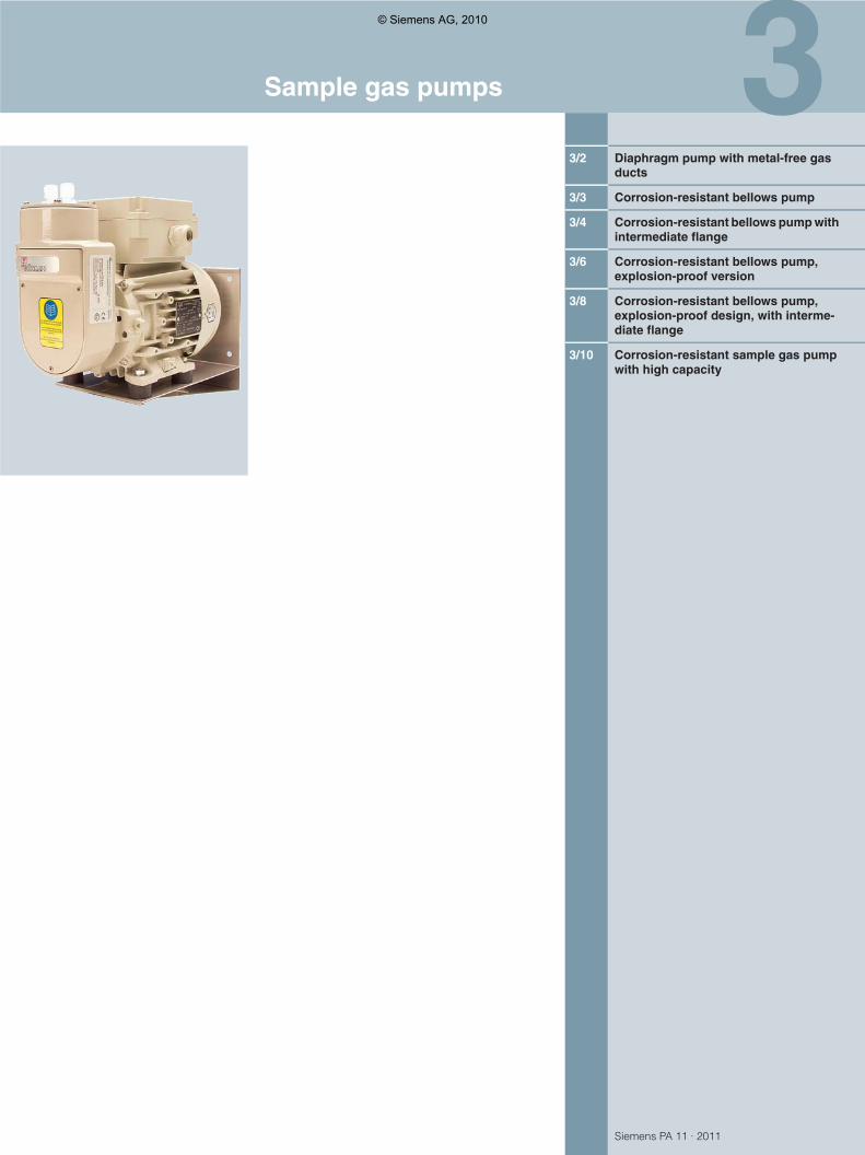
33/2 Diaphragm pump with metal-free gas
ducts
3/3 Corrosion-resistant bellows pump
3/4 Corrosion-resistant bellows pump with intermediate flange
3/6 Corrosion-resistant bellows pump, explosion-proof version
3/8 Corrosion-resistant bellows pump, explosion-proof design, with interme-diate flange
3/10 Corrosion-resistant sample gas pump with high capacity
Sample gas pumps
© Siemens AG, 2010
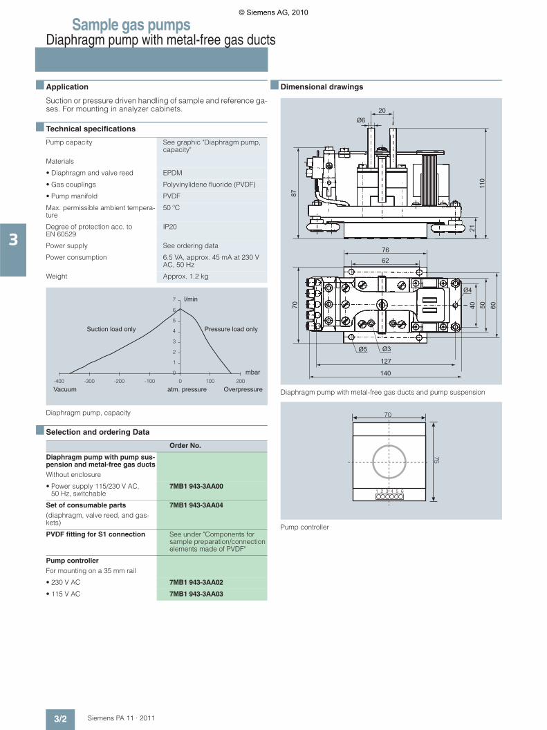
Sample gas pumpsDiaphragm pump with metal-free gas ducts
3/2 Siemens PA 11 · 2011
3
■ Application
Suction or pressure driven handling of sample and reference ga-ses. For mounting in analyzer cabinets.
■ Technical specifications
Diaphragm pump, capacity
■ Selection and ordering Data
■ Dimensional drawings
Diaphragm pump with metal-free gas ducts and pump suspension
Pump controller
Pump capacity See graphic "Diaphragm pump, capacity"
Materials
• Diaphragm and valve reed EPDM
• Gas couplings Polyvinylidene fluoride (PVDF)
• Pump manifold PVDF
Max. permissible ambient tempera-ture
50 ºC
Degree of protection acc. to EN 60529
IP20
Power supply See ordering data
Power consumption 6.5 VA, approx. 45 mA at 230 V AC, 50 Hz
Weight Approx. 1.2 kg
Order No.
Diaphragm pump with pump sus-pension and metal-free gas ductsWithout enclosure
• Power supply 115/230 V AC, 50 Hz, switchable
7MB1 943-3AA00
Set of consumable parts(diaphragm, valve reed, and gas-kets)
7MB1 943-3AA04
PVDF fitting for S1 connection See under "Components for sample preparation/connection elements made of PVDF"
Pump controllerFor mounting on a 35 mm rail
• 230 V AC 7MB1 943-3AA02
• 115 V AC 7MB1 943-3AA03
Pressure load onlySuction load only
Vacuum atm. pressure Overpressure
l/min
mbar
Ø620
6276
127
140
Ø5 Ø3
Ø4
4021
110
87
50 6070
© Siemens AG, 2010
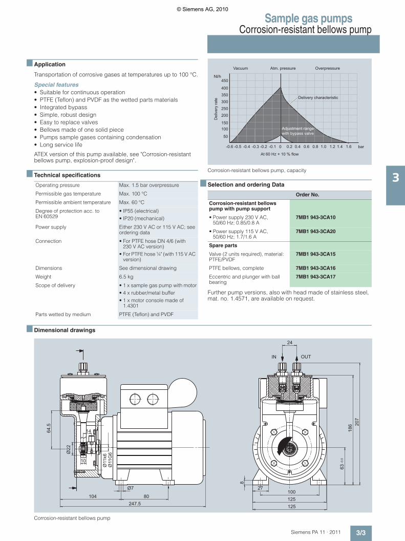
Sample gas pumpsCorrosion-resistant bellows pump
3/3Siemens PA 11 · 2011
3
■ Application
Transportation of corrosive gases at temperatures up to 100 °C.
Special features• Suitable for continuous operation• PTFE (Teflon) and PVDF as the wetted parts materials• Integrated bypass • Simple, robust design• Easy to replace valves• Bellows made of one solid piece• Pumps sample gases containing condensation• Long service life
ATEX version of this pump available, see "Corrosion-resistant bellows pump, explosion-proof design".
■ Technical specifications
Corrosion-resistant bellows pump, capacity
■ Selection and ordering Data
Further pump versions, also with head made of stainless steel, mat. no. 1.4571, are available on request.
■ Dimensional drawings
Corrosion-resistant bellows pump
Operating pressure Max. 1.5 bar overpressure
Permissible gas temperature Max. 100 °C
Permissible ambient temperature Max. 60 °C
Degree of protection acc. to EN 60529
• IP55 (electrical) • IP20 (mechanical)
Power supply Either 230 V AC or 115 V AC; see ordering data
Connection • For PTFE hose DN 4/6 (with 230 V AC version)
• For PTFE hose ¼" (with 115 V AC version)
Dimensions See dimensional drawing
Weight 6.5 kg
Scope of delivery • 1 x sample gas pump with motor• 4 x rubber/metal buffer• 1 x motor console made of
1.4301
Parts wetted by medium PTFE (Teflon) and PVDF
Order No.
Corrosion-resistant bellows pump with pump support
• Power supply 230 V AC, 50/60 Hz; 0.85/0.8 A
7MB1 943-3CA10
• Power supply 115 V AC, 50/60 Hz; 1.7/1.6 A
7MB1 943-3CA20
Spare parts
Valve (2 units required), material: PTFE/PVDF
7MB1 943-3CA15
PTFE bellows, complete 7MB1 943-3CA16
Eccentric and plunger with ball bearing
7MB1 943-3CA17
Atm. pressure OverpressureVacuum
Del
iver
y ra
te
Nl/h
Delivery characteristic
At 60 Hz + 10 % flow
Adjustment range with bypass valve
-0.6 -0.5 -0.4 -0.3 -0.2 -0.1 0.2 0.4 0.6 0.8 1.0 1.2 1.4 1.6 bar
400
350
300
250
200
150100
50
450
0
Ø22
10
64.5
247.5
-0.5
IN OUT
100125
Ø
11k6
14
Ø
11G
6
Ø7
104 80
63
27
8
2418
6 207
125
© Siemens AG, 2010

Sample gas pumpsCorrosion-resistant bellows pump with intermediate flange
3/4 Siemens PA 11 · 2011
3
■ Application
Transportation of corrosive gases at temperatures up to 160 °C.
To facilitate use in hot applications, the pump head and drive motor can be installed separate from each other. The pump has a transfer flange designed in two parts; one half is installed in a heated cabinet, and the other half - carrying the drive motor - is mounted on the outside. An additional motor console is not pro-vided. If the wall stability is insufficient, it should be mechanically strengthened prior to installation of the pump.
Pump without bypass.
The pump should be installed horizontally.
The pump head can be rotated as required when installing. If the gas carries condensation, the pump must be installed with the valves pointing downward.
Special features• Suitable for continuous operation• PTFE (Teflon) and PEEK as the wetted parts materials• Simple, robust design• Easy to replace valves• Bellows made of one solid piece• Pumps sample gases containing condensation• Long service life• When installing the pump head in a cabinet, the wall thickness
may be up to 30 mm.
ATEX version of this pump available, see "Corrosion-resistant bellows pump, explosion-proof design with intermediate flange".
■ Technical specifications
Corrosion-resistant bellows pump with intermediate flange, capacity
■ Selection and ordering Data
Further pump versions, also with head made of stainless steel 1.4571, are available on request.
Pump capacity • See graphic "Corrosion-resistant bellows pump, capacity"
• Fixed
Operating pressure Max. 1.5 bar overpressure
Permissible gas temperature Max. 160 °C
Max. permissible ambient tempera-ture
• 60 °C (motor) • 100 °C (pump head)
Degree of protection acc. to EN 60529
• IP55 (electrical) • IP20 (mechanical)
Power supply Either 230 V AC or 115 V AC; see ordering data
Connection • For PTFE hose DN 4/6 (with 230 V AC version)
• For PTFE hose 1/4" / 1/6" (with 115 V AC version)
Dimensions See dimensional drawing
Weight 7.5 kg
Scope of delivery • 1 x pump head with intermediate flange
• 1 x motor• 1 x coupling flange• 1 x coupling (2 x hub,1 x ring ge-
ar)• 4 x bolts M6 x 16• 1 x mounting ring
Parts wetted by medium PTFE (Teflon) and PEEK
Order No.
Corrosion-resistant bellows pump with intermediate flange
• Power supply 230 V AC, 50/60 Hz; 0.85/0.8 A
7MB1 943-3CA21
• Power supply 115 V AC, 50/60 Hz; 1.7/1.6 A
7MB1 943-3CA22
Spare parts
Set of 2 valves, material: PTFE/PEEK
7MB1 943-3CA18
PTFE bellows, complete 7MB1 943-3CA16
Eccentric and plunger with ball bearing
7MB1 943-3CA17
Atm. pressure OverpressureVacuum
Del
iver
y ra
te
Nl/h
Delivery characteristic
At 60 Hz + 10 % flow
-0.6 -0.5 -0.4 -0.3 -0.2 -0.1 0.2 0.4 0.6 0.8 1.0 1.2 1.4 1.6 bar
400
350
300
250
200
150100
50
450
0
© Siemens AG, 2010

Sample gas pumpsCorrosion-resistant bellows pump with intermediate flange
3/5Siemens PA 11 · 2011
3
■ Dimensional drawings
Corrosion-resistant bellows pump with intermediate flange
Wall
27100
85
345
211
148
12563
80
229116
M6
Ø7
24
max. 30
© Siemens AG, 2010
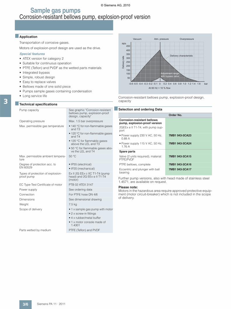
Sample gas pumpsCorrosion-resistant bellows pump, explosion-proof version
3/6 Siemens PA 11 · 2011
3
■ Application
Transportation of corrosive gases.
Motors of explosion-proof design are used as the drive.
Special features• ATEX version for category 2• Suitable for continuous operation• PTFE (Teflon) and PVDF as the wetted parts materials• Integrated bypass• Simple, robust design• Easy to replace valves• Bellows made of one solid piece• Pumps sample gases containing condensation• Long service life
■ Technical specifications
Corrosion-resistant bellows pump, explosion-proof design, capacity
■ Selection and ordering Data
Further pump versions, also with head made of stainless steel 1.4571, are available on request.
Please note: Motors in the hazardous area require approved protective equip-ment (motor circuit-breaker) which is not included in the scope of delivery.
Pump capacity See graphic "Corrosion-resistant bellows pump, explosion-proof design, capacity"
Operating pressure Max. 1.5 bar overpressure
Max. permissible gas temperature • 140 °C for non-flammable gases and T3
• 120 °C for non-flammable gases and T4
• 120 °C for flammable gases above the LEL and T3
• 50 °C for flammable gases abo-ve the LEL and T4
Max. permissible ambient tempera-ture
50 °C
Degree of protection acc. to EN 60529
• IP55 (electrical) • IP20 (mechanical)
Types of protection of explosion-proof pump
Ex II 2G EEx c IIC T1-T4 (pump head) and 2G EEx e II T1-T4 (motor)
EC Type-Test Certificate of motor PTB 02 ATEX 3147
Power supply See ordering data
Connection For PTFE hose DN 4/6
Dimensions See dimensional drawing
Weight 7.5 kg
Scope of delivery • 1 x sample gas pump with motor• 2 x screw-in fittings• 4 x rubber/metal buffer• 1 x motor console made of
1.4301
Parts wetted by medium PTFE (Teflon) and PVDF
Order No.
Corrosion-resistant bellows pump, explosion-proof version2GEEx e II T1-T4, with pump sup-port
• Power supply 230 V AC, 50 Hz, 0.88 A
7MB1 943-3CA23
• Power supply 115 V AC, 50 Hz, 1.76 A
7MB1 943-3CA24
Spare parts
Valve (2 units required), material: PTFE/PVDF
7MB1 943-3CA15
PTFE bellows, complete 7MB1 943-3CA16
Eccentric and plunger with ball bearing
7MB1 943-3CA17
Atm. pressure OverpressureVacuum
Del
iver
y ra
te
Nl/h
Delivery characteristic
At 60 Hz + 10 % flow
Adjustment range with bypass valve
-0.6 -0.5 -0.4 -0.3 -0.2 -0.1 0.2 0.4 0.6 0.8 1.0 1.2 1.4 1.6 bar
400
350
300
250
200
150100
50
450
0
© Siemens AG, 2010
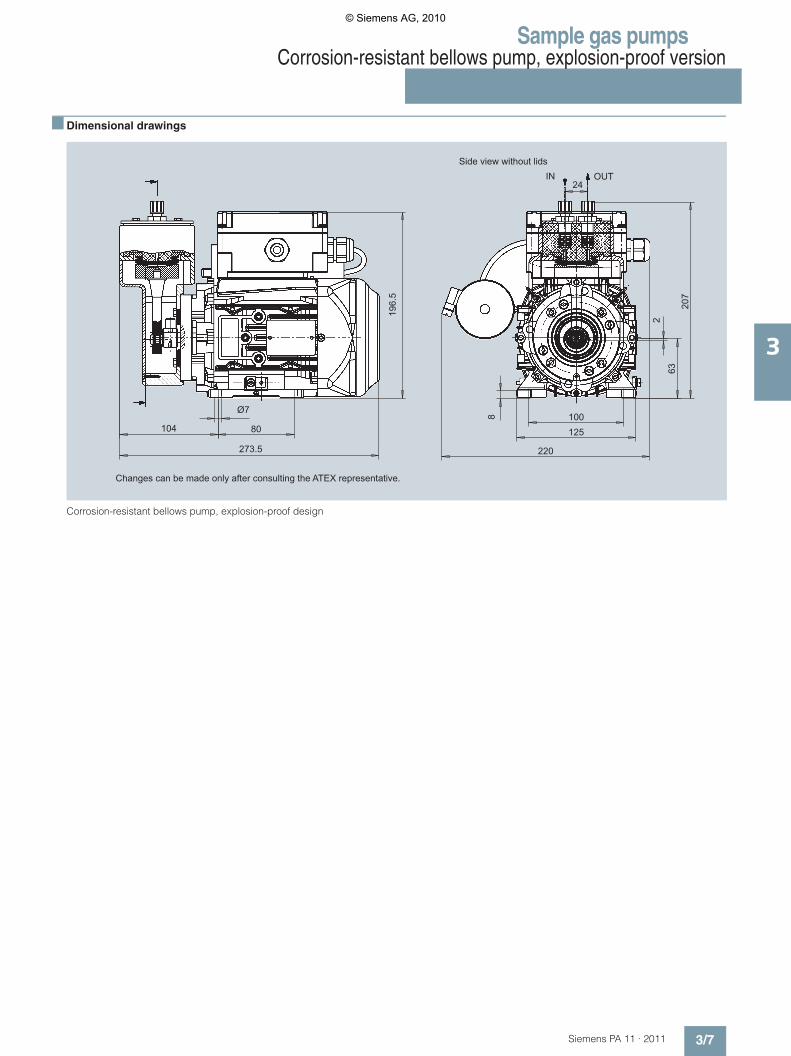
Sample gas pumpsCorrosion-resistant bellows pump, explosion-proof version
3/7Siemens PA 11 · 2011
3
■ Dimensional drawings
Corrosion-resistant bellows pump, explosion-proof design
196.
5
273.5
IN OUTSide view without lids
Changes can be made only after consulting the ATEX representative.
207
220
801041008
632
24
Ø7
125
© Siemens AG, 2010

Sample gas pumpsCorrosion-resistant bellows pump, explosion-proof design, with intermediate flange
3/8 Siemens PA 11 · 2011
3
■ Application
Transportation of corrosive gases.
Motors of explosion-proof design are used as the drive.
To facilitate use in hot applications, the pump head and drive motor can be installed separate from each other. The pump has a transfer flange designed in two parts; one half is installed in a heated cabinet, and the other half - carrying the drive motor - is mounted on the outside. An additional motor console is not pro-vided. If the wall stability is insufficient, it should be mechanically strengthened prior to installation of the pump.
Pump without bypass.
The pump should be installed horizontally.
The pump head can be rotated as required when installing. If the gas carries condensation, the pump must be installed with the valves pointing downward.
Special features• ATEX version for category 2• Suitable for continuous operation• PTFE (Teflon) and PEEK as the wetted parts materials• Simple, robust design• Easy to replace valves• Bellows made of one solid piece• Pumps sample gases containing condensation• Long service life• When installing the pump head in a cabinet, the wall thickness
may be up to 30 mm
■ Technical specifications
Corrosion-resistant bellows pump, explosion-proof design, with interme-diate flange, capacity
■ Selection and ordering Data
Further pump versions, also with head made of stainless steel mat. no. 1.4571, are available on request.
Please note: Motors in the hazardous area require approved protective equip-ment (motor circuit-breaker) which is not included in the scope of delivery.
Atm. pressure OverpressureVacuum
Del
iver
y ra
te
Nl/h
Delivery characteristic
At 60 Hz + 10 % flow
-0.6 -0.5 -0.4 -0.3 -0.2 -0.1 0.2 0.4 0.6 0.8 1.0 1.2 1.4 1.6 bar
400
350
300
250
200
150100
50
450
0
Pump capacity • See graphic "Corrosion-resistant bellows pump, explosion-proof design with intermediate flange, capacity"
• Fixed
Operating pressure Max. 1.5 bar overpressure
Max. permissible gas temperature and associated pump head tempe-rature
• 120 °C for non-flammable gases and T3 (pump head max. 100 °C)
• 80 °C for non-flammable gases and T4 (pump head max. 80 °C)
• 100 °C for flammable gases and T3 (pump head max. 80 °C)
• 50 °C for flammable gases and T4 (pump head max. 50 °C)
Max. permissible ambient tempera-ture
• 50 °C (motor) • 50 … 100 °C (pump head), de-
pendent on the type of gas and gas temperature (see previous line)
Degree of protection acc. to EN 60529
• IP55 (electrical)• IP20 (mechanical)
Types of protection of explosion-proof pump
Ex II 2G EEx c IIC T1-T4 (pump head) and 2G EEx e II T1-T4 (motor)
EC Type-Test Certificate of motor PTB 02 ATEX 3147
Power supply See ordering data
Connection For PTFE hose DN 4/6
Dimensions See dimensional drawing
Weight 8.5 kg
Scope of delivery • 1 x pump head with intermediate flange
• 1 x motor• 1 x coupling flange• 1 x coupling (2 x hub,1 x ring ge-
ar)• 4 x bolts M6 x 16• 1 x mounting ring
Parts wetted by medium PTFE (Teflon) and PEEK
Order No.
Corrosion-resistant bellows pump, explosion-proof version2GEEx e II T1-T4, with intermedi-ate flange
Power supply 230 V AC, 50 Hz, 0.88 A
7MB1 943-3CA25
Power supply 115 V AC, 50 Hz, 1.76 A
7MB1 943-3CA26
Spare parts
Set of 2 valves, material: PTFE/PEEK
7MB1 943-3CA18
PTFE bellows, complete 7MB1 943-3CA16
Eccentric and plunger with ball bearing
7MB1 943-3CA17
© Siemens AG, 2010
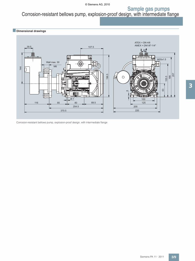
Sample gas pumpsCorrosion-resistant bellows pump, explosion-proof design, with intermediate flange
3/9Siemens PA 11 · 2011
3
■ Dimensional drawings
Corrosion-resistant bellows pump, explosion-proof design, with intermediate flange
254.5
Wall max. 30
370.5
107.5
196.
5
89.5
39.5
155.
5
M20x1.5
205
220
Ø 7
8085116
144
24
63
186 20
7
M6
8
ATEX = DN 4/6AMEX = DN1/6"-1/4"
100125
© Siemens AG, 2010
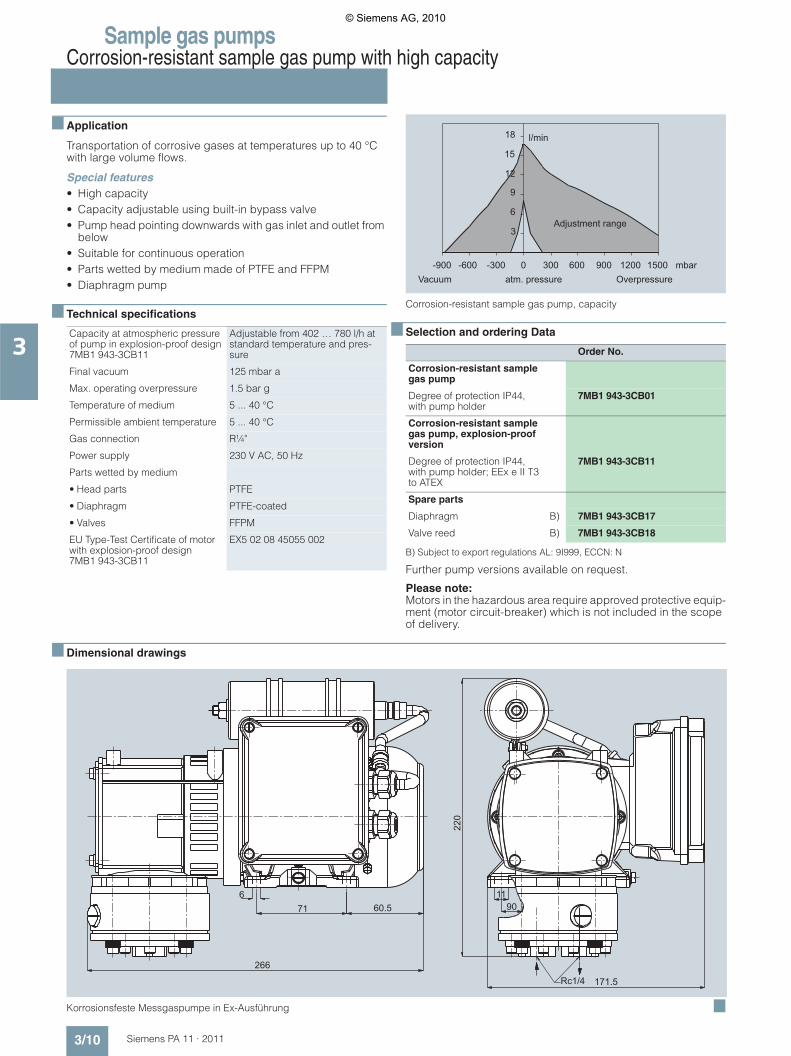
Sample gas pumpsCorrosion-resistant sample gas pump with high capacity
3/10 Siemens PA 11 · 2011
3
■ Application
Transportation of corrosive gases at temperatures up to 40 °C with large volume flows.
Special features• High capacity• Capacity adjustable using built-in bypass valve• Pump head pointing downwards with gas inlet and outlet from
below• Suitable for continuous operation• Parts wetted by medium made of PTFE and FFPM• Diaphragm pump
■ Technical specifications
Corrosion-resistant sample gas pump, capacity
■ Selection and ordering Data
B) Subject to export regulations AL: 9I999, ECCN: N
Further pump versions available on request.
Please note: Motors in the hazardous area require approved protective equip-ment (motor circuit-breaker) which is not included in the scope of delivery.
■ Dimensional drawings
Korrosionsfeste Messgaspumpe in Ex-Ausführung ■
Capacity at atmospheric pressure of pump in explosion-proof design 7MB1 943-3CB11
Adjustable from 402 … 780 l/h at standard temperature and pres-sure
Final vacuum 125 mbar a
Max. operating overpressure 1.5 bar g
Temperature of medium 5 ... 40 °C
Permissible ambient temperature 5 ... 40 °C
Gas connection R¼"
Power supply 230 V AC, 50 Hz
Parts wetted by medium
• Head parts PTFE
• Diaphragm PTFE-coated
• Valves FFPM
EU Type-Test Certificate of motor with explosion-proof design 7MB1 943-3CB11
EX5 02 08 45055 002
Order No.
Corrosion-resistant sample gas pump
Degree of protection IP44, with pump holder
7MB1 943-3CB01
Corrosion-resistant sample gas pump, explosion-proof version
Degree of protection IP44, with pump holder; EEx e II T3 to ATEX
7MB1 943-3CB11
Spare parts
Diaphragm B) 7MB1 943-3CB17
Valve reed B) 7MB1 943-3CB18
Adjustment range
OverpressureVacuum atm. pressurembar
l/min
600 900 1200 15003000-300-600-900
3
6
9
12
15
18
60.5
171.5
716
266
220
1190
Rc1/4
© Siemens AG, 2010
Siemens PA 11 · 2011
44/2 Temperature-controlled,
heated sample gas lines4/2 Non-replaceable Teflon core
Max. 120 °C, can be shortened4/3 Non-replaceable Teflon core
Max. 200 °C4/4 Non-replaceable Teflon core, Max. 190 °C
for FIDAMAT total hydrocarbon analyzer
4/5 Temperature-controlled, heated sample gas filter
4/5 Max. 180 °C, for FIDAMAT total hydrocarbon analyzer
Heated sample gas lines
© Siemens AG, 2010

Heated sample gas linesTemperature-controlled, heated sample gas linesNon-replaceable Teflon coreMax. 120 °C, can be shortened
4/2 Siemens PA 11 · 2011
4
■ Design
■ Technical specifications
■ Dimensional drawings
Temperature-controlled, heated sample gas line for operating temperatu-res up to max. 120 °C, non-replaceable Teflon core, can be shortened
■ Selection and ordering Data
Note:
The complete ordering data for a heated sample gas line must include both items I and II.
Hose connection and ter-mination
Silicone end cap
Heating Heating band, routed in parallel
Thermal insulation Thermo-fleece (CFC-free, flame retardant)
Outer sheath Polyamide corrugated hose PA12 black, waterproof, flame retardant acc. to UL94 HB, thermally stable from -50 … +120 °C, short-term +150 °C
Temperature sensor Pt100 in 2-wire system
Heat conductor/PE con-ductor
Copper braiding
Power supply connection Power supply and sensor cables with com-mon outlet, end sleeves, l = 3 000 mm
Implemented tests acc. to VDE 0721 Part 1• High-voltage test• Insulation resistance test
Max. permissible operating tempe-rature
• Switched on 120 °C
• Switched off 200 °C
Max. length of heating circuit 100 m
Max. production length 100 m
Distance between contacts 0.6 m
Safety class I
Degree of protection IP54
Outer diameter Approx. 43 mm
Smallest bending radius 300 mm
Max. permissible operating pres-sure
6 bar for DN(NW)4, 4 bar for DN(NW)6; at 200 °C
Power supply 230 V AC, 50 Hz
Rated power 40 W/m
Weight (heating hose) Approx. 0.8 kg/m
Ø6
or 8
PE 100
PE
N
L
Pt 100l = 3 m
Ø43
1 000 200
l = ____ m
105
200
Ø48
Order No.
Item I
Preassembled pack for temperature-cont-rolled, heated sample gas line for operating temperatures up to 120 °C; can be shortened (delivery unit 1 line) Both ends preassembled, with PTFE hoseNon-replaceable Teflon core, with 1 Pt100 tem-perature sensor
7MB1 943-2AB13
Item II
Length-dependent data(delivery unit 1 m) Outer sheath Polyamide corrugated hose (PA12)Hose
• PTFE hose 4/6 mm 7MB1 943-2AB10
• PTFE hose 6/8 mm 7MB1 943-2AB12
Temperature-controlled, heated sample gas line for operating temperatures up to 120 °C; can be shortened Neither end preassembled, with PTFE hose, with 1 Pt100 temperature sensor Outer sheath Polyamide corrugated hose (PA12)Hose
• PTFE hose 4/6 mm 7MB1 943-2AB14
• PTFE hose 6/8 mm 7MB1 943-2AB16
Preassembled pack for connection of heated sample gas line (cabinet end)Comprising:• 1 silicon end cap• 1 connections set for heating band• 1 Pt 100 temperature sensor
7MB1 943-2AB20
Preassembled pack for connection of heated sample gas line (sampling end)Comprising:• 1 silicon end cap• 1 connections set for heating band
7MB1 943-2AB22
Temperature-resistant adhesive tape (33 m)Note:10 m are required to assemble a hose
7MB1 943-2AB24
Silicone adhesive (1 tube)Note: Half a tube is required to assemble a hose
7MB1 943-2AB26
Recommended temperature controller 3RS1 042-1GW70
© Siemens AG, 2010
Heated sample gas linesTemperature-controlled, heated sample gas lines
Non-replaceable Teflon coreMax. 200 °C
4/3Siemens PA 11 · 2011
4
■ Design
■ Technical specifications
■ Dimensional drawings
Temperature-controlled, heated sample gas line for operating temperatu-res up to max. 200 °C, non-replaceable Teflon core
■ Selection and ordering Data
Note:
The complete ordering data for a heated sample gas line must include both items I and II.
B) Subject to export regulations AL: 9I999, ECCN: N
Example for ordering
The following is required:
Temperature-controlled, heated sample gas line for operating temperatures up to 200 ºC, with straight connection fittings at both ends, outer sheath made of corrugated hose PA12, PTFE hose 4/6 mm, 10 m long
Order as follows:
7MB1 943-2BA00 + 10 x 7MB1 943-2AA01
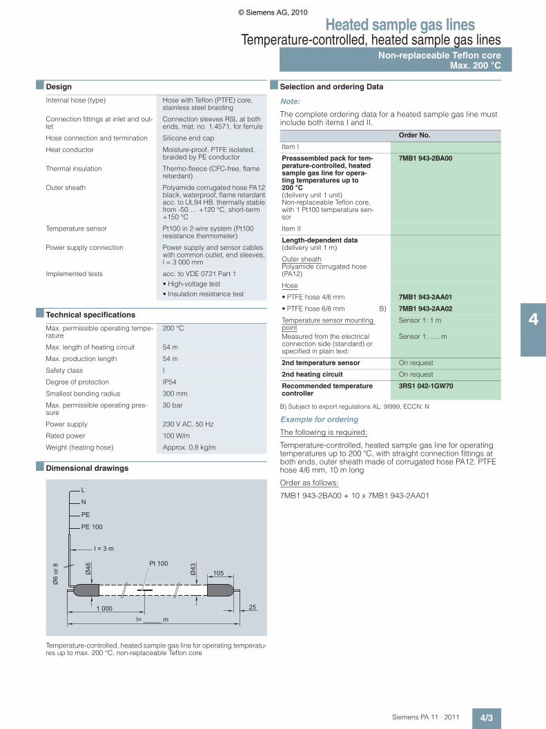
Internal hose (type) Hose with Teflon (PTFE) core, stainless steel braiding
Connection fittings at inlet and out-let
Connection sleeves RSL at both ends, mat. no. 1.4571, for ferrule
Hose connection and termination Silicone end cap
Heat conductor Moisture-proof, PTFE isolated, braided by PE conductor
Thermal insulation Thermo-fleece (CFC-free, flame retardant)
Outer sheath Polyamide corrugated hose PA12 black, waterproof, flame retardant acc. to UL94 HB, thermally stable from -50 … +120 °C, short-term +150 °C
Temperature sensor Pt100 in 2-wire system (Pt100 resistance thermometer)
Power supply connection Power supply and sensor cables with common outlet, end sleeves, l = 3 000 mm
Implemented tests acc. to VDE 0721 Part 1 • High-voltage test• Insulation resistance test
Max. permissible operating tempe-rature
200 °C
Max. length of heating circuit 54 m
Max. production length 54 m
Safety class I
Degree of protection IP54
Smallest bending radius 300 mm
Max. permissible operating pres-sure
30 bar
Power supply 230 V AC, 50 Hz
Rated power 100 W/m
Weight (heating hose) Approx. 0.8 kg/m
Ø6
or 8
Ø48
Ø43
25
l= _____ m
1 000
105
PE 100
PE
N
L
Pt 100
l = 3 m
Order No.
Item I
Preassembled pack for tem-perature-controlled, heated sample gas line for opera-ting temperatures up to 200 °C(delivery unit 1 unit)Non-replaceable Teflon core, with 1 Pt100 temperature sen-sor
7MB1 943-2BA00
Item II
Length-dependent data(delivery unit 1 m)
Outer sheath Polyamide corrugated hose (PA12)
Hose
• PTFE hose 4/6 mm 7MB1 943-2AA01
• PTFE hose 6/8 mm B) 7MB1 943-2AA02
Temperature sensor mounting point
Sensor 1: 1 m
Measured from the electrical connection side (standard) or specified in plain text:
Sensor 1: ..... m
2nd temperature sensor On request
2nd heating circuit On request
Recommended temperature controller
3RS1 042-1GW70
© Siemens AG, 2010
Heated sample gas linesTemperature-controlled, heated sample gas linesNon-replaceable Teflon core, Max. 190 °Cfor FIDAMAT total hydrocarbon analyzer
4/4 Siemens PA 11 · 2011
4
■ Design
■ Technical specifications
■ Selection and ordering Data
Note:
The complete ordering data for a heated sample gas line must include both items I and II.
■ Dimensional drawings
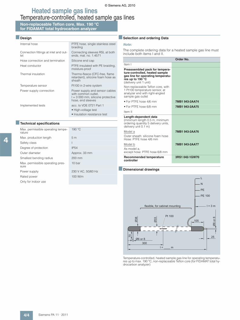
Temperature-controlled, heated sample gas line for operating temperatu-res up to max. 190 °C, non-replaceable Teflon core (for FIDAMAT total hy-drocarbon analyzer)
Internal hose PTFE hose, single stainless steel braiding
Connection fittings at inlet and out-let
Connecting sleeves RSL at both ends, mat. no. 1.4571
Hose connection and termination Silicone end cap
Heat conductor PTFE-insulated with PE braiding, moisture-proof
Thermal insulation Thermo-fleece (CFC-free, flame retardant), silicone foam hose as sheath
Temperature sensor Pt100 in 2-wire system
Power supply connection Power supply and sensor cables with common outlet, l = 3 000 mm, silicone protective hose, end sleeves
Implemented tests acc. to VDE 0721 Part 1• High-voltage test• Insulation resistance test
Max. permissible operating tempe-rature
190 °C
Max. production length 5 m
Safety class I
Degree of protection IP54
Outer diameter Approx. 33 mm
Smallest bending radius 200 mm
Max. permissible operating pres-sure
10 bar
Power supply 230 V AC, 50/60 Hz
Rated power 100 W/m
Only for indoor use
Order No.
Item I
Preassembled pack for tempera-ture-controlled, heated sample gas line for operating temperatu-res up to 190 °C(delivery unit 1 unit)Non-replaceable Teflon core, with 1 Pt100 temperature sensor, at analyzer end with right-angled sample gas outlet
• For PTFE hose 4/6 mm 7MB1 943-2AA74
• For PTFE hose 6/8 mm 7MB1 943-2AA75
Item II
Length-dependent data(minimum length 0.5 m, minimum ordering quantity 5 delivery units, delivery unit 0.1 m)
Model a Outer sheath: silicone foam hoseHose: PTFE hose 4/6 mm
7MB1 943-2AA76
Model b As model a, except hose: PTFE hose 6/8 mm
7MB1 943-2AA77
Recommended temperature controller
3RS1 042-1GW70
flexible, for cabinet mounting
Ø6 or 8
Ø6
or 8
25
105Ø38
300
70
Ø33
l = ____ m
PE 100
PE
N
L
Pt 100
l = 3 m
© Siemens AG, 2010
Heated sample gas linesTemperature-controlled, heated sample gas filter
Max. 180 °C,for FIDAMAT total hydrocarbon analyzer
4/5Siemens PA 11 · 2011
4
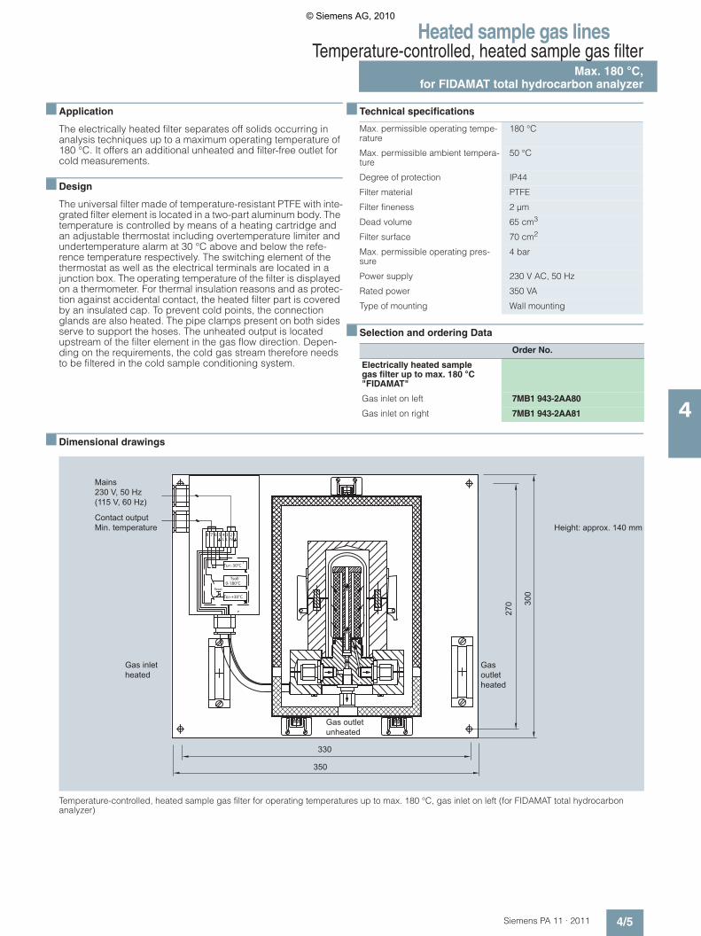
■ Application
The electrically heated filter separates off solids occurring in analysis techniques up to a maximum operating temperature of 180 °C. It offers an additional unheated and filter-free outlet for cold measurements.
■ Design
The universal filter made of temperature-resistant PTFE with inte-grated filter element is located in a two-part aluminum body. The temperature is controlled by means of a heating cartridge and an adjustable thermostat including overtemperature limiter and undertemperature alarm at 30 °C above and below the refe-rence temperature respectively. The switching element of the thermostat as well as the electrical terminals are located in a junction box. The operating temperature of the filter is displayed on a thermometer. For thermal insulation reasons and as protec-tion against accidental contact, the heated filter part is covered by an insulated cap. To prevent cold points, the connection glands are also heated. The pipe clamps present on both sides serve to support the hoses. The unheated output is located upstream of the filter element in the gas flow direction. Depen-ding on the requirements, the cold gas stream therefore needs to be filtered in the cold sample conditioning system.
■ Technical specifications
■ Selection and ordering Data
■ Dimensional drawings
Temperature-controlled, heated sample gas filter for operating temperatures up to max. 180 °C, gas inlet on left (for FIDAMAT total hydrocarbon analyzer)
Max. permissible operating tempe-rature
180 °C
Max. permissible ambient tempera-ture
50 °C
Degree of protection IP44
Filter material PTFE
Filter fineness 2 μm
Dead volume 65 cm3
Filter surface 70 cm2
Max. permissible operating pres-sure
4 bar
Power supply 230 V AC, 50 Hz
Rated power 350 VA
Type of mounting Wall mounting
Order No.
Electrically heated sample gas filter up to max. 180 °C "FIDAMAT"
Gas inlet on left 7MB1 943-2AA80
Gas inlet on right 7MB1 943-2AA81
Tu<-30°C
To>+30°C
Tsoll
L3 2 1N
5 4678L'
0-180°CReset
Gas inletheated
Gas outletunheated
Gas outletheated
Height: approx. 140 mmContact outputMin. temperature
Mains230 V, 50 Hz(115 V, 60 Hz)
330
350
300
270
© Siemens AG, 2010
Heated sample gas linesTemperature-controlled, heated sample gas filterMax. 180 °C,for FIDAMAT total hydrocarbon analyzer
4/6 Siemens PA 11 · 2011
4
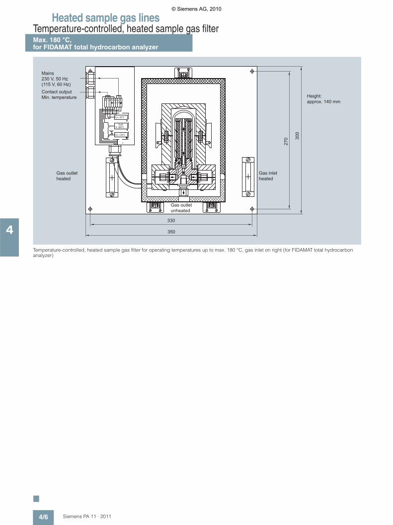
Temperature-controlled, heated sample gas filter for operating temperatures up to max. 180 °C, gas inlet on right (for FIDAMAT total hydrocarbon analyzer)
■
Tu<-30°C
To>+30°C
Tsoll
L3 2 1
N5 4678
L'
0-180°CReset
Gas inletheated
Gas outletunheated
Gas outletheated
Height: approx. 140 mm
Contact outputMin. temperature
Mains230 V, 50 Hz(115 V, 60 Hz)
330
350
300
270
© Siemens AG, 2010
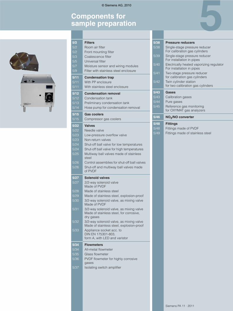
Siemens PA 11 · 2011
55/2 Filters5/2 Room air filter5/2 Front mounting filter5/3 Coalescence filter5/5 Universal filter5/7 Moisture sensor and wiring modules5/9 Filter with stainless steel enclosure
5/11 Condensation trap5/11 With PP enclosure5/11 With stainless steel enclosure
5/12 Condensation removal5/12 Condensation tank5/13 Preliminary condensation tank5/14 Hose pump for condensation removal
5/15 Gas coolers5/15 Compressor gas coolers
5/22 Valves5/22 Needle valve5/23 Low-pressure overflow valve5/23 Non-return valves5/24 Shut-off ball valve for low temperatures5/24 Shut-off ball valve for high temperatures5/25 Multiway ball valves made of stainless
steel5/26 Control assemblies for shut-off ball valves5/26 Shut-off and multiway ball valves made
of PVDF
5/27 Solenoid valves5/27 2/2-way solenoid valve
Made of PVDF5/28 Made of stainless steel5/29 Made of stainless steel, explosion-proof5/30 3/2-way solenoid valve, as mixing valve
Made of PVDF5/31 3/2-way solenoid valve, as mixing valve
Made of stainless steel, for corrosive, dry gases
5/32 3/2-way solenoid valve, as mixing valveMade of stainless steel, explosion-proof
5/33 Appliance socket acc. to DIN EN 175301-803,form A, with LED and varistor
5/34 Flowmeters5/34 All-metal flowmeter5/35 Glass flowmeter5/36 PVDF flowmeter for highly corrosive
gases5/37 Isolating switch amplifier
5/38 Pressure reducers5/38 Single-stage pressure reducer
For calibration gas cylinders5/39 Single-stage pressure reducer
For installation in pipes5/40 Electrically heated vaporizing regulator
For installation in pipes5/41 Two-stage pressure reducer
for calibration gas cylinders5/42 Twin cylinder station
for two calibration gas cylinders
5/43 Gases5/43 Calibration gases5/44 Pure gases5/45 Reference gas monitoring
for OXYMAT gas analyzers
5/46 NO2/NO converter
5/48 Fittings5/48 Fittings made of PVDF5/49 Fittings made of stainless steel
Components for sample preparation
© Siemens AG, 2010
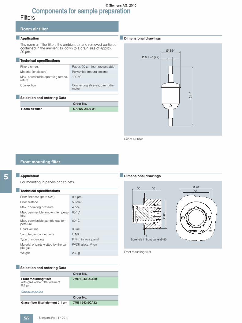
Components for sample preparationFilters
Room air filter
5/2 Siemens PA 11 · 2011
5
■ Application
The room air filter filters the ambient air and removed particles contained in the ambient air down to a grain size of approx. 20 �m.
■ Technical specifications
■ Selection and ordering Data
■ Dimensional drawings
Room air filter
■ Application
For mounting in panels or cabinets.
■ Technical specifications
■ Selection and ordering Data
Consumables
■ Dimensional drawings
Front mounting filter
Filter element Paper, 20 �m (non-replaceable)
Material (enclosure) Polyamide (natural colors)
Max. permissible operating tempe-rature
100 °C
Connection Connecting sleeves, 6 mm dia-meter
Order No.
Room air filter C79127-Z400-A1
Ø 6.1 - 8 (2X)
±1
±2
Filter fineness (pore size) 0.1 �m
Filter surface 50 cm²
Max. operating pressure 4 bar
Max. permissible ambient tempera-ture
80 °C
Max. permissible sample gas tem-perature
80 °C
Dead volume 30 ml
Sample gas connections G1/8
Type of mounting Fitting in front panel
Material of parts wetted by the sam-ple gas
PVDF, glass, Viton
Weight 280 g
Order No.
Front mounting filterwith glass-fiber filter element 0.1 μm
7MB1 943-2CA30
Order No.
Glass-fiber filter element 0.1 μm 7MB1 943-2CA32
Borehole in front panel Ø 50
30 36 Ø 7058
Ø 6
5
M4
Front mounting filter
© Siemens AG, 2010

Components for sample preparationFilters
Coalescence filter
5/3Siemens PA 11 · 2011
5
■ Application
For mounting in sample conditioning systems.
■ Design
To remove aerosols (fine drops of liquid) from the gas stream.
The collected condensation is drained in the case of pressurized systems via automatic condensation drain valves, or in the case of vacuum systems via hose pumps.
Caution! Condensation can be corrosive. Observe the accident preven-tion regulations and other directives.
The coalescence filter comprises:• Filter head (PVDF)• Filter bubble (Duran glass)• Gasket material (Viton)
Special features• User-friendly and unique quick-release connection, allows ex-
tremely simple and rapid replacement of the filter element wi-thout tools
• Additional connection in filter head (G ¼") for moisture sensor or bypass
• Connection of automatic condensation drains possible
For use in hazardous areas
The filters comply with the basic safety requirements of directive 94/9/EC and are thus suitable for use in hazardous areas (Zone 1, Group IIB). Non-flammable gases and flammable gases of Group IIB or IIC (which can be occasionally explosive in normal operation, Zone1) can be passed through the filters depending on the filter element used.
The information in the associated Operating Instructions must be observed!
■ Technical specifications
■ Selection and ordering Data
Accessories
Gas connections Inlet and outlet, 2 x G¼ female thread diagonally opposite on side
Sample gas pressure Max. 4 bar
Filter surface 28 cm²
Dead volume 73 ml
Type of mounting Wall mounting
Operating temperature Max. 100 °C
Weight Approx. 0.24 kg
Order No.
Coalescence filter 7MB1 943-2AC12with filter element made of borosili-cate fiber
Order No.
Filter element 7MB1 943-2AC13made of borosilicate fiber (1 unit)
© Siemens AG, 2010

Components for sample preparationFilters
Coalescence filter
5/4 Siemens PA 11 · 2011
5
■ Dimensional drawings
Coalescence filter
View A
39.5
6.5
25.5
Section B-B
Middle junction„in-out“
G1/4
G1/
4
G1/
4
17
60
B B
GL 25
35
55
103
138
29
65
© Siemens AG, 2010
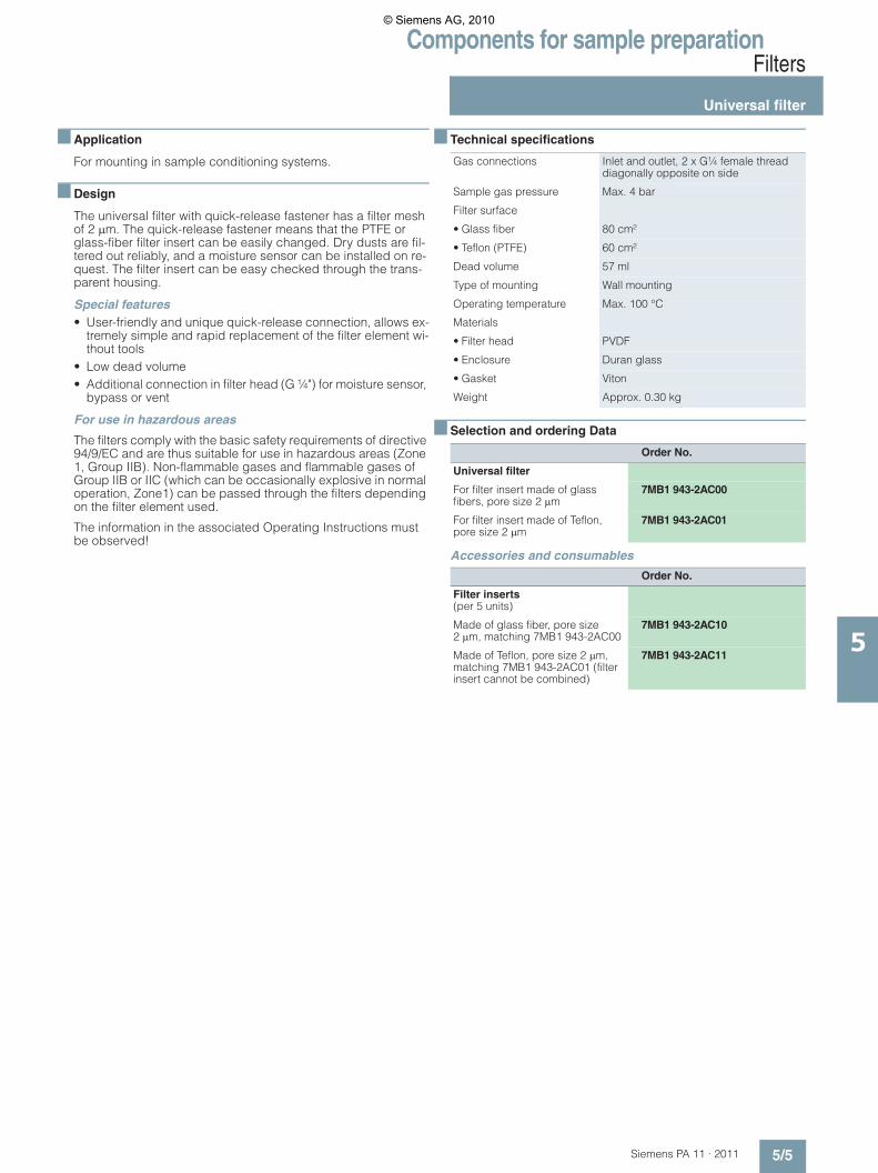
Components for sample preparationFilters
Universal filter
5/5Siemens PA 11 · 2011
5
■ Application
For mounting in sample conditioning systems.
■ Design
The universal filter with quick-release fastener has a filter mesh of 2 �m. The quick-release fastener means that the PTFE or glass-fiber filter insert can be easily changed. Dry dusts are fil-tered out reliably, and a moisture sensor can be installed on re-quest. The filter insert can be easy checked through the trans-parent housing.
Special features• User-friendly and unique quick-release connection, allows ex-
tremely simple and rapid replacement of the filter element wi-thout tools
• Low dead volume• Additional connection in filter head (G ¼") for moisture sensor,
bypass or vent
For use in hazardous areas
The filters comply with the basic safety requirements of directive 94/9/EC and are thus suitable for use in hazardous areas (Zone 1, Group IIB). Non-flammable gases and flammable gases of Group IIB or IIC (which can be occasionally explosive in normal operation, Zone1) can be passed through the filters depending on the filter element used.
The information in the associated Operating Instructions must be observed!
■ Technical specifications
■ Selection and ordering Data
Accessories and consumables
Gas connections Inlet and outlet, 2 x G¼ female thread diagonally opposite on side
Sample gas pressure Max. 4 bar
Filter surface
• Glass fiber 80 cm²
• Teflon (PTFE) 60 cm²
Dead volume 57 ml
Type of mounting Wall mounting
Operating temperature Max. 100 °C
Materials
• Filter head PVDF
• Enclosure Duran glass
• Gasket Viton
Weight Approx. 0.30 kg
Order No.
Universal filter
For filter insert made of glass fibers, pore size 2 �m
7MB1 943-2AC00
For filter insert made of Teflon, pore size 2 �m
7MB1 943-2AC01
Order No.
Filter inserts(per 5 units)
Made of glass fiber, pore size 2 �m, matching 7MB1 943-2AC00
7MB1 943-2AC10
Made of Teflon, pore size 2 �m, matching 7MB1 943-2AC01 (filter insert cannot be combined)
7MB1 943-2AC11
© Siemens AG, 2010
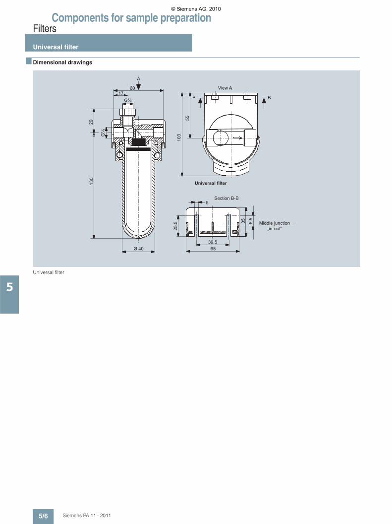
Components for sample preparationFilters
Universal filter
5/6 Siemens PA 11 · 2011
5
■ Dimensional drawings
Universal filter
Section B-B
Universal filter
View A
Middle junction„in-out“
39.5
25.5 6.
5
1760
5
65Ø 40
G¼G
¼
2913
0
103
55
35
A
BB
© Siemens AG, 2010

Components for sample preparationFilters
Moisture sensor and wiring modules
5/7Siemens PA 11 · 2011
5
■ Application
The moisture sensor is used to signal the penetration of moisture in sample gas treatment systems in order to prevent the dama-ging of measuring cells by condensation. It is fitted in the gas stream and already responds to low quantities of moisture; it therefore is not dependent on an accumulation of condensation. Once the fault has been eliminated, the moisture sensor is imme-diately dried by the flow of gas. It is maintenance-free.
The moisture sensor is connected to a wiring module with which the sample gas pump can be switched off and an alarm signal triggered. Once the sample gas has passed the moisture sen-sor, it first flows through the filter housing before reaching the analyzer. This buffer provides an additional safety period for a re-sponse by the wiring module if the sensor detects moisture. There are three different wiring modules for selection depending on the conditions of use.
■ Design
The moisture sensor can be used together with the universal fil-ter, the coalescence filter, or with flow adapters. Together with the wiring module, the moisture sensor has an open-circuit mo-nitoring function.
For use in hazardous areas
The moisture sensor can only be used in the ATEX area together with the associated wiring module with intrinsically-safe output (II 2G EEx ib IIC T5). The wiring module itself must be installed in a non-hazardous environment.
■ Technical specifications
■ Selection and ordering Data
Max. permissible operating temperature
50 °C
Max. permissible operating pressure
2 bar; other version for higher pressure on request
Cable length (moisture sen-sor)
4 m
Materials PVDF, stainless steel mat. no. 1.4571, epoxy resin
Weight Approx. 0.1 kg
Wiring modules • With intrinsically-safe output for ap-plications accor-ding to ATEX
• Rail mounting
• Non-Ex applica-tions in ac-cordance with IEC General Pur-pose
• Rail mounting
Power supply 230 V AC or 115 V AC48 … 62 Hz
24 V DC ± 10 %
Ex protection class II(1)G [EEx ia] IIC -
Ex certificate TÜV 00 ATEX 1604 -
Max. cable length 70 m 4 m
Degree of protection acc. to EN 60529
• Device IP40 IP40
• Terminal strip IP20 IP20
Operating temperature -25 ... +60 °C -20 ... +60 °C
Type of mounting DIN rail 35 mm DIN rail 35 mm
Dimensions (H x W x D) in mm 99 x 22.5 x 120 75 x 70 x 109
Weight Approx. 0.2 kg Approx. 0.2 kg
Order No.
Moisture sensorCable length 4 m, connection G¼
7MB1 943-2AC51
Wiring modules
With intrinsically-safe output for applications according to ATEX
• For 1 moisture sensor, power supply 230 V AC, 48 … 62 Hz
7MB1 943-2AC40
• For 1 moisture sensor, power supply 115 V AC, 48 … 62 Hz
7MB1 943-2AC41
For use in accordance with IEC General Purpose
• For max. 2 moisture sensors, power supply 24 V DC
7MB1 943-2AC42
Flow adapter
Made of PVDF, for moisture sensor for installation in sample gas line
7MB1 943-2AC06
Made of stainless steel mat. no. 1.4571, for installation in piping
7MB1 943-2AC43
© Siemens AG, 2010
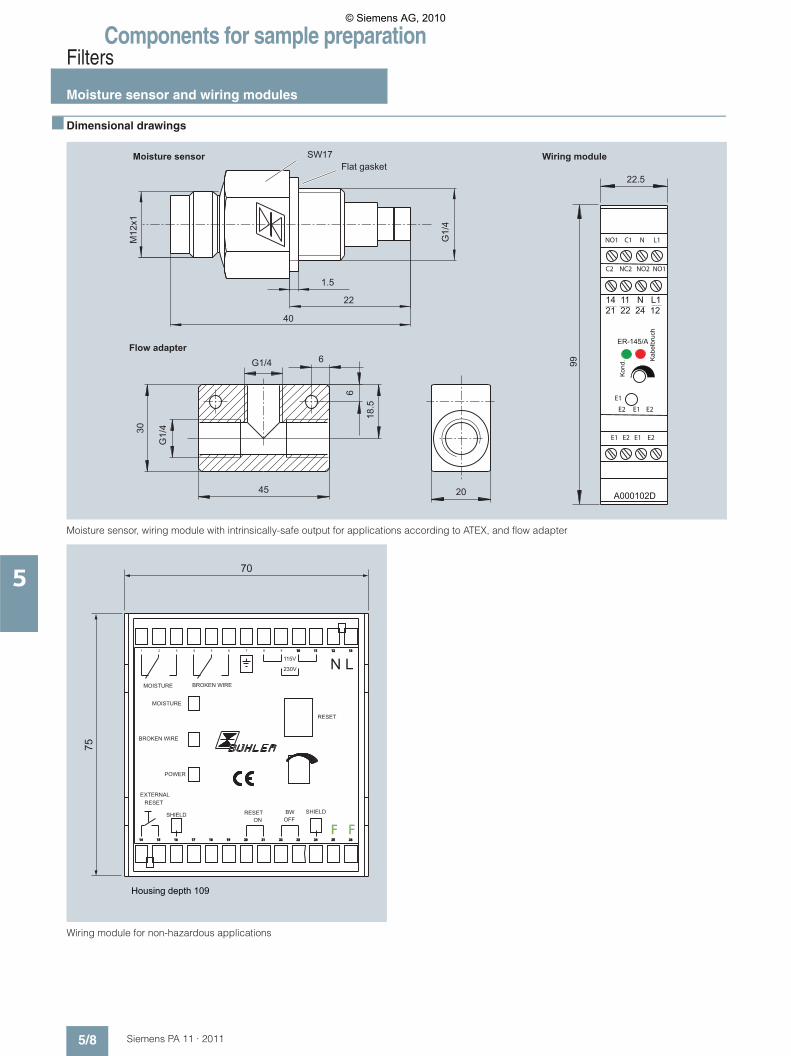
Components for sample preparationFilters
Moisture sensor and wiring modules
5/8 Siemens PA 11 · 2011
5
■ Dimensional drawings
Moisture sensor, wiring module with intrinsically-safe output for applications according to ATEX, and flow adapter
Wiring module for non-hazardous applications
14 11 N L1
C2 NC2 NO2 NO1
E1 E2 E1 E2
E2 E1 E2
E1
NO1 C1 N L1
21 22 24 12
ER-145/A
Kon
d. Kab
elbr
uch
A000102D
22.5
18.5
Wiring moduleMoisture sensor
Flow adapter
Flat gasket
1.5
99
45
66
30
G1/
4
20
G1/4
M12
x1
22
G1/
4
40
SW17
Housing depth 109
MOISTURE BROKEN WIRE
SHIELD SHIELD
115V
230V
ON OFFRESET BW
BROKEN WIRE
MOISTURE
RESETEXTERNAL
POWER
RESET
N L
F F
1 2 3 4 5 6 7 8 9 1010 1111 1212 1313
1414 1515 1616 1717 1818 1919 2020 2121 2222 2323 2424 2525 2626
© Siemens AG, 2010

Components for sample preparationFilters
Filter with stainless steel enclosure
5/9Siemens PA 11 · 2011
5
■ Application
For filtering gases under process conditions.
■ Design
Inlet and outlet identification for use as dust filter (gas path from outside to inside).
Special features• Extremely simple and rapid replacement of filter element wit-
hout tools• Low dead volume• Possibility for (automatic) draining of condensation through
connection thread (NPT ¼") in the filter bubbleCaution! Condensation can be corrosive. Observe the acci-dent prevention regulations and other directives.
The warning information in the associated Operating Instruc-tions must be observed!
■ Technical specifications
■ Selection and ordering Data
Max. permissible operating pres-sure
350 bar (at max. 150 °C operating temperature)
Max. permissible operating tem-perature
150 °C
Dead volume with filter element 18 ml
Connection thread (inlet, outlet, drain)
Female thread ¼ NPT
Materials
• Body Steel SS 316 L, mat. no. 1.4404
• Gasket Viton, FEP sheath
Weight Approx. 0.8 kg
Filter elements
Material Glass fiber / epoxy resin
Max. permissible temperature 150 °C
Filter fineness (pore size) 2 / 5 / 10 μm
Order No.
Stainless steel enclosure (empty)
7MB1 943-2AC44
Mounting bracket 7MB1 943-2AC45
Plug NPT 1/4 7MB1 943-2AC46
Filter elements
Filter fineness 2 μm 7MB1 943-2AC47
Filter fineness 5 μm 7MB1 943-2AC48
Filter fineness 10 μm 7MB1 943-2AC50
© Siemens AG, 2010
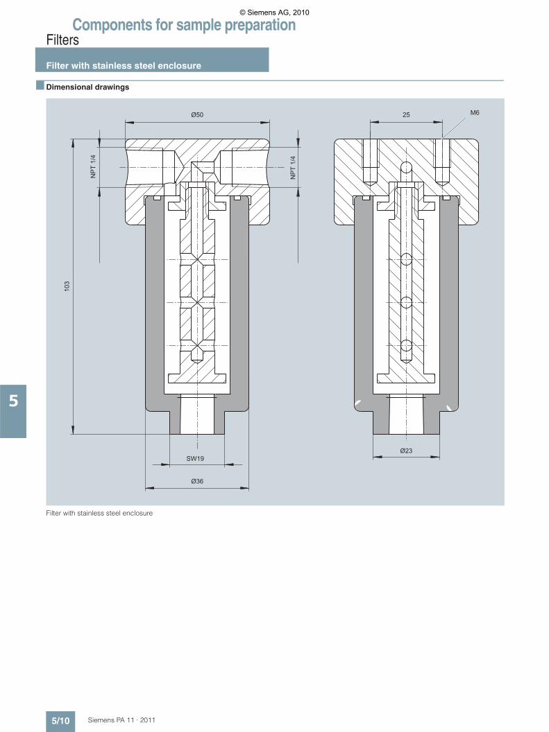
Components for sample preparationFilters
Filter with stainless steel enclosure
5/10 Siemens PA 11 · 2011
5
■ Dimensional drawings
Filter with stainless steel enclosure
M6
NP
T 1/
4
Ø23
NP
T 1/
4
SW19
Ø36
Ø50
103
25
© Siemens AG, 2010
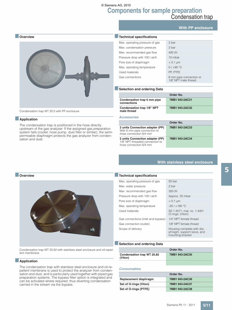
Components for sample preparationCondensation trap
With PP enclosure
5/11Siemens PA 11 · 2011
5
■ Overview
Condensation trap WT 20.5 with PP enclosure
■ Application
The condensation trap is positioned in the hose directly upstream of the gas analyzer. If the assigned gas preparation system fails (cooler, hose pump, dust filter or similar), the semi-permeable diaphragm protects the gas analyzer from conden-sation and dust.
■ Technical specifications
■ Selection and ordering Data
Accessories
■ Overview
Condensation trap WT 20.82 with stainless steel enclosure and oil-repel-lent membrane
■ Application
The condensation trap with stainless steel enclosure and oil-re-pellent membrane is used to protect the analyzer from conden-sation and dust, and is particularly used together with piped gas preparation systems. The bypass filter option is integrated and can be activated where required, thus diverting condensation carried in the stream via the bypass.
■ Technical specifications
■ Selection and ordering Data
Consumables
Max. operating pressure of gas 2 bar
Max. condensation pressure 2 bar
Max. recommended gas flow 400 l/h
Pressure drop with 100 l air/h 10 mbar
Pore size of diaphragm < 0.1 μm
Max. operating temperature 0 / +90 °C
Used materials PP, PTFE
Gas connections 6 mm pipe connection or 1/8" NPT male thread
Order No.
Condensation trap 6 mm pipe connections
7MB1 943-2AC31
Condensation trap 1/8" NPT male thread
7MB1 943-2AC32
Order No.
2 units Connection adapter (PP)With 6 mm pipe connection to hose connection 6/4 mm
7MB1 943-2AC33
2 units Connection adapter (PP) 1/8" NPT threaded connection to hose connection 6/4 mm
7MB1 943-2AC34
Max. operating pressure of gas 50 bar
Max. water pressure 2 bar
Max. recommended gas flow 300 l/h
Pressure drop with 100 l air/h Approx. 25 mbar
Pore size of diaphragm < 0.1 μm
Max. operating temperature -20 / +190 °C
Used materials SS 1.4571, mat. no. 1.4401O-rings: (Viton)
Gas connections (inlet and bypass) 1/4" NPT female thread
Gas connection (outlet) 1/8" NPT female thread
Scope of delivery Housing complete with dia-phragm, support sieve, and mounting bracket
Order No.
Condensation trap WT 20.82 (Viton)
7MB1 943-2AC35
Order No.
Replacement diaphragm 7MB1 943-2AC36
Set of O-rings (Viton) 7MB1 943-2AC37
Set of O-rings (PTFE) 7MB1 943-2AC38
With stainless steel enclosure
© Siemens AG, 2010
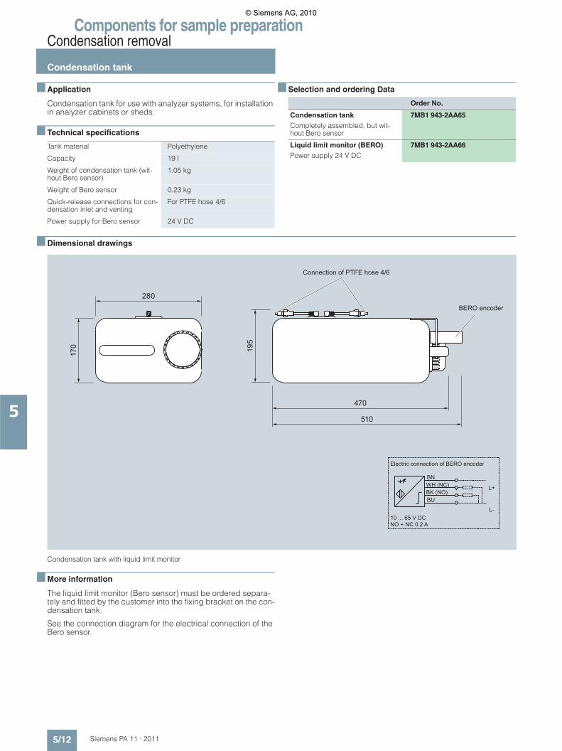
Components for sample preparationCondensation removal
Condensation tank
5/12 Siemens PA 11 · 2011
5
■ Application
Condensation tank for use with analyzer systems, for installation in analyzer cabinets or sheds.
■ Technical specifications
■ Selection and ordering Data
■ Dimensional drawings
Condensation tank with liquid limit monitor
■ More information
The liquid limit monitor (Bero sensor) must be ordered separa-tely and fitted by the customer into the fixing bracket on the con-densation tank.
See the connection diagram for the electrical connection of the Bero sensor.
Tank material Polyethylene
Capacity 19 l
Weight of condensation tank (wit-hout Bero sensor)
1.05 kg
Weight of Bero sensor 0.23 kg
Quick-release connections for con-densation inlet and venting
For PTFE hose 4/6
Power supply for Bero sensor 24 V DC
Order No.
Condensation tankCompletely assembled, but wit-hout Bero sensor
7MB1 943-2AA65
Liquid limit monitor (BERO)Power supply 24 V DC
7MB1 943-2AA66
Electric connection of BERO encoder
BN
BU
10 ... 65 V DCNO + NC 0.2 A
BK (NO)WH (NC)
Connection of PTFE hose 4/6
BERO encoder
L+
L-
© Siemens AG, 2010

Components for sample preparationCondensation removal
Preliminary condensation tank
5/13Siemens PA 11 · 2011
5
■ Application
For use where condensation is very high. Fitted upstream of the gas cooler.
■ Selection and ordering Data
Accessories and consumables
1) The number of gaskets required for the gas inlet/outlet and the condensa-tion outlet depends on the hose diameter.
B) Subject to export regulations AL: 9I999, ECCN: N
■ Dimensional drawings
Preliminary condensation trap
Order No.
Preliminary condensation tank 7MB1 943-2AA50Completely made of glass, with mounting clamp, cap for couplings and gaskets for hose 4/6
Order No.
Mounting clampHolder for preliminary conden-sation trap
7MB1 943-2AA48
Condensation trapMade of glass
7MB1 943-2AA41
CapFor couplings (3 x required)
7MB1 943-2AA44
Gasket 1)
For hose 4/6 B) 7MB1 943-2AA45
For hose 6/8 B) 7MB1 943-2AA46
For hose 8/10 B) 7MB1 943-2AA47
Wall thickness 2
Ø 50
Ø 12GL 18
258
198
30
225
55
R4
© Siemens AG, 2010
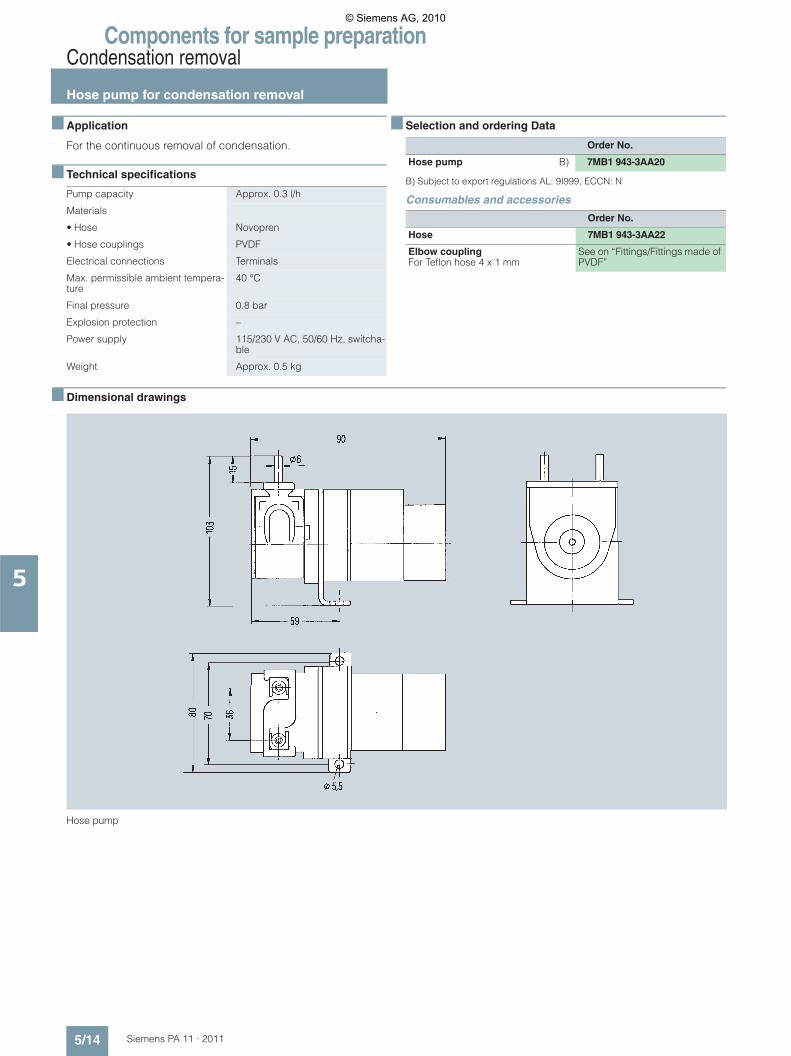
Components for sample preparationCondensation removal
Hose pump for condensation removal
5/14 Siemens PA 11 · 2011
5
■ Application
For the continuous removal of condensation.
■ Technical specifications
■ Selection and ordering Data
B) Subject to export regulations AL: 9I999, ECCN: N
Consumables and accessories
■ Dimensional drawings
Hose pump
Pump capacity Approx. 0.3 l/h
Materials
• Hose Novopren
• Hose couplings PVDF
Electrical connections Terminals
Max. permissible ambient tempera-ture
40 °C
Final pressure 0.8 bar
Explosion protection –
Power supply 115/230 V AC, 50/60 Hz, switcha-ble
Weight Approx. 0.5 kg
Order No.
Hose pump B) 7MB1 943-3AA20
Order No.
Hose 7MB1 943-3AA22
Elbow couplingFor Teflon hose 4 x 1 mm
See on “Fittings/Fittings made of PVDF”
© Siemens AG, 2010
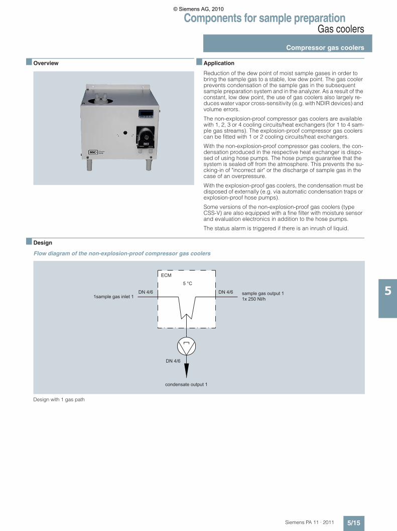
Components for sample preparationGas coolers
Compressor gas coolers
5/15Siemens PA 11 · 2011
5
■ Overview
■ Application
Reduction of the dew point of moist sample gases in order to bring the sample gas to a stable, low dew point. The gas cooler prevents condensation of the sample gas in the subsequent sample preparation system and in the analyzer. As a result of the constant, low dew point, the use of gas coolers also largely re-duces water vapor cross-sensitivity (e.g. with NDIR devices) and volume errors.
The non-explosion-proof compressor gas coolers are available with 1, 2, 3 or 4 cooling circuits/heat exchangers (for 1 to 4 sam-ple gas streams). The explosion-proof compressor gas coolers can be fitted with 1 or 2 cooling circuits/heat exchangers.
With the non-explosion-proof compressor gas coolers, the con-densation produced in the respective heat exchanger is dispo-sed of using hose pumps. The hose pumps guarantee that the system is sealed off from the atmosphere. This prevents the su-cking-in of "incorrect air" or the discharge of sample gas in the case of an overpressure.
With the explosion-proof gas coolers, the condensation must be disposed of externally (e.g. via automatic condensation traps or explosion-proof hose pumps).
Some versions of the non-explosion-proof gas coolers (type CSS-V) are also equipped with a fine filter with moisture sensor and evaluation electronics in addition to the hose pumps.
The status alarm is triggered if there is an inrush of liquid.
■ Design
Flow diagram of the non-explosion-proof compressor gas coolers
Design with 1 gas path
1sample gas inlet 1sample gas output 11x 250 Nl/h
condensate output 1
DN 4/6
DN 4/6 DN 4/6
ECM
5 °C
© Siemens AG, 2010
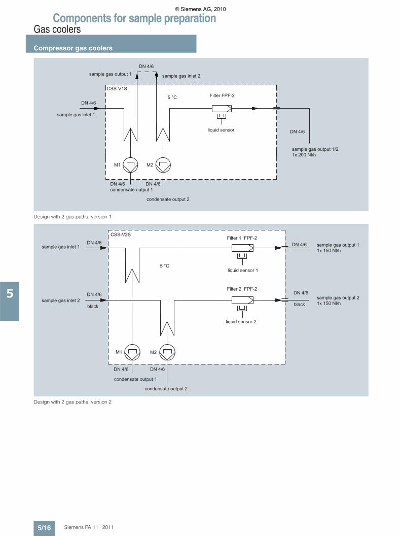
Components for sample preparationGas coolers
Compressor gas coolers
5/16 Siemens PA 11 · 2011
5
Design with 2 gas paths; version 1
Design with 2 gas paths; version 2
sample gas inlet 2
sample gas inlet 1
sample gas output 1/21x 200 Nl/h
sample gas output 1
condensate output 1
condensate output 2
liquid sensor
DN 4/6
DN 4/6
DN 4/6
DN 4/6
DN 4/6
5 °C Filter FPF-2
M1 M2
CSS-V1S
sample gas inlet 1
sample gas inlet 2 sample gas output 21x 150 Nl/hblackblack
condensate output 1
condensate output 2
liquid sensor 1
liquid sensor 2
sample gas output 11x 150 Nl/h
DN 4/6DN 4/6
M1 M2
5 °C
DN 4/6
DN 4/6
CSS-V2S
DN 4/6
DN 4/6
Filter 2 FPF-2
Filter 1 FPF-2
© Siemens AG, 2010

Components for sample preparationGas coolers
Compressor gas coolers
5/17Siemens PA 11 · 2011
5
Design with 3 gas paths
Design with 4 gas paths
sample gas inlet 1
sample gas inlet 2
sample gas inlet 3
sample gas output 11x 100 Nl/h
sample gas output 21x 100 Nl/h
sample gas output 31x 100 Nl/h
condensate output 1
condensate output 2
condensate output 3
DN 4/6
DN 4/6
DN 4/6
DN 4/6DN 4/6DN 4/6
DN 4/6
DN 4/6
DN 4/6 CSS-V3S
M3M2M1
5 °C
1/4" femalesample gas inlet 1
1/4" femalesample gas inlet 2
1/4" femalesample gas inlet 3
1/4" femalesample gas inlet 4
1/4" female 1x 250 Nl/hsample gas output 1
1/4" female 1x 250 Nl/hsample gas output 2
1/4" female 1x 250 Nl/hsample gas output 3
1/4" female 1x 250 Nl/hsample gas output 4
condensate output 1
condensate output 2
condensate output 3
condensate output 4
DN 4/6DN 4/6
DN 4/6
M3M2M1 M4
DN 4/6
5 °C
ECS
© Siemens AG, 2010

Components for sample preparationGas coolers
Compressor gas coolers
5/18 Siemens PA 11 · 2011
5
■ Technical specifications
Non-Ex-protected compressor gas coolers
1) Technical data with maximum values must be evaluated with consideration of the total cooling capacity at 25 °C and an outlet dew point of 5 °C.
Type Quantity ECM CSS-V1SCSS-V2S
CSS-V3S ECS
Gas paths / heat exchangers (HE)Material PVDF
Units 1 21) 3 4
Integrated hose pump (SR25.2) Units 1 2 3 4
Integrated fine filter with moisture sensor Units 0 1 or 2 0 0
Gas flow l/h Max. 2501) Max. 2 x 1501) Max. 3 x 1001) Max. 4 x 2501)
Gas inlet temperature °C Max. 1801) Max. 1051) Max. 1801)
Gas inlet dew point °C Max. 801)
Gas outlet dew point °C Factory setting +5; range of adjustment +2 … 7
Ambient temperature °C 10 … 50 10 … 40 5 … 45
Gas pressure bar a Max. 2 0.7 ... 1.4 Max. 2
Dead volume/HE ml 100 25 70
Wetted parts material PVDF, Novopren PVDF, Novopren, PVC, FPM, PPH, PTFE PVDF, Novopren
Operational readiness min <15 10 <30
Power consumption VA Max. 220 Max. 280
Power supply connection 230 V; 50 Hz115 V; 60 Hz
230 V; 50 HzOptional 115; 50 … 60 Hz
230 V; 50 Hz115 V; 60 Hz
Electric connection Terminals 2.5 mm² Appliance plug with 2 m cable Terminals 2.5 mm²
Status alarm(max. 250 V 2 A AC/DC 500 VA, 50 W)
2 changeover con-tacts (isolated)
CSS-V1S: 1 changeover contact as com-mon alarmCSS-V2S: 2 changeover contacts as common alarm
2 changeover con-tacts (isolated)
Degree of protection for enclosure IP 20 (EN 60529)
Enclosure design/type of mounting Wall mounting 19" rack mounting or wall mounting
Enclosure dimensions (W x H x D) mm 270 x 270 x 316 483 x 268 x 348 483 x 360 x 406
Weight kg Approx. 14 Approx. 23 Approx. 34
Gas/condensation connections For PTFE hose 4/6
Housing color RAL 9003 7035 9003
Version 1:Type CSS-V1S
Heat exchangers in series: HE 1 for preliminary condensation; HE 2 for constant dew point temperature of sample and calibration gases. Calibration gas valves and sample gas pump can be fitted between the the outlet HE1 and the inlet HE2.A fine filter accessible from the front is fitted downstream of HE2. To protect subsequent analyzers from an inrush of liquid, a liquid alarm sensor is integrated in the filter.
Version 2:Type CSS-V2S
Heat exchangers in parallel: 2 separate heat exchangers arranged in parallel, each with a downstream filter and liquid alarm sensor; e.g. for measuring two different sample gases in one analyzer cabinet.
© Siemens AG, 2010

Components for sample preparationGas coolers
Compressor gas coolers
5/19Siemens PA 11 · 2011
5
Ex-protected compressor gas coolers
1) Technical data with maximum values must be evaluated with consideration of the total cooling capacity at 25 °C and an outlet dew point of 5 °C.
Type Quantity EC-Ex 1SS EC-Ex 2SS
Gas ducts / heat exchangers (HE)Material stainless steel; mat. no. 1.4571
Units 1 2
Gas flow l/h Max. 2501) Max. 2 x 2501)
Gas inlet temperature °C Max. 1801)
Gas inlet dew point °C Max. 801)
Gas outlet dew point °C Factory setting +5; range of adjustment 2 … 7
Ambient temperature °C 5 … 45
Gas pressure bar a Max. 11
Dead volume/HE ml 70 25
Wetted parts material Stainless steel PVDF, Neoprene, PVC, FPM, PPH, PTFE
Operational readiness min <30 10
Power consumption VA Approx. 280 Max. 220
Power supply connection 230 V; 50 Hz; ± 10 %Optional 115 V; 50 … 60 Hz; ± 10 %
Electric connection Terminals 2.5 mm² Appliance plug with 2 m cable
Status alarm(max. 230 V 2 A AC/DC 100 VA, 50 W)
1 changeover contact
Degree of protection IP 20 (EN 60529)
Ex approval (ATEX) II 2G EEx pedq [ib] IIC T4
Enclosure design/type of mounting 19" rack mounting or wall mounting
Enclosure dimensions (W x H x D) mm 483 x 360 x 450 483 x 268 x 302
Weight kg Approx. 40 Approx. 22
Gas connections G1/4 inch (female)Optionally available with NPT 1/4 inch
Condensation connections G3/8 inch (female)Optionally available with NPT 3/8 inch
Housing color RAL 9003
© Siemens AG, 2010
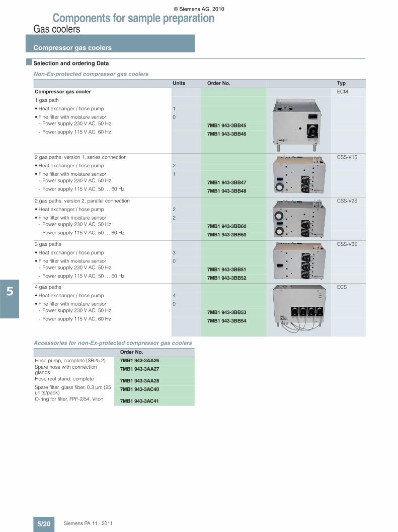
Components for sample preparationGas coolers
Compressor gas coolers
5/20 Siemens PA 11 · 2011
5
■ Selection and ordering Data
Non-Ex-protected compressor gas coolers
Accessories for non-Ex-protected compressor gas coolers
Units Order No. Typ
Compressor gas cooler ECM
1 gas path
• Heat exchanger / hose pump 1
• Fine filter with moisture sensor 0- Power supply 230 V AC, 50 Hz 7MB1 943-3BB45- Power supply 115 V AC, 60 Hz 7MB1 943-3BB46
2 gas paths, version 1, series connection
CSS-V1S
• Heat exchanger / hose pump 2
• Fine filter with moisture sensor 1- Power supply 230 V AC, 50 Hz 7MB1 943-3BB47- Power supply 115 V AC, 50 … 60 Hz 7MB1 943-3BB48
2 gas paths, version 2, parallel connection
CSS-V2S
• Heat exchanger / hose pump 2
• Fine filter with moisture sensor 2- Power supply 230 V AC, 50 Hz 7MB1 943-3BB60- Power supply 115 V AC, 50 … 60 Hz 7MB1 943-3BB50
3 gas paths
CSS-V3S
• Heat exchanger / hose pump 3
• Fine filter with moisture sensor 0- Power supply 230 V AC, 50 Hz 7MB1 943-3BB51- Power supply 115 V AC, 50 … 60 Hz 7MB1 943-3BB52
4 gas paths
ECS
• Heat exchanger / hose pump 4
• Fine filter with moisture sensor 0- Power supply 230 V AC, 50 Hz 7MB1 943-3BB53- Power supply 115 V AC, 60 Hz 7MB1 943-3BB54
Order No.
Hose pump, complete (SR25.2) 7MB1 943-3AA26Spare hose with connection glands
7MB1 943-3AA27
Hose reel stand, complete 7MB1 943-3AA28Spare filter, glass fiber, 0.3 μm (25 units/pack)
7MB1 943-3AC40
O-ring for filter, FPF-2/54, Viton 7MB1 943-3AC41
© Siemens AG, 2010
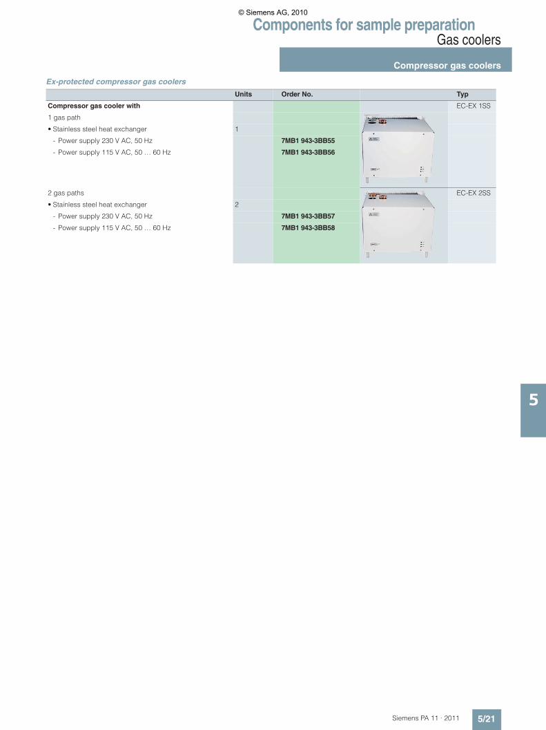
Components for sample preparationGas coolers
Compressor gas coolers
5/21Siemens PA 11 · 2011
5
Ex-protected compressor gas coolers
Units Order No. Typ
Compressor gas cooler with EC-EX 1SS
1 gas path
• Stainless steel heat exchanger 1
- Power supply 230 V AC, 50 Hz 7MB1 943-3BB55
- Power supply 115 V AC, 50 … 60 Hz 7MB1 943-3BB56
2 gas paths
EC-EX 2SS
• Stainless steel heat exchanger 2
- Power supply 230 V AC, 50 Hz 7MB1 943-3BB57
- Power supply 115 V AC, 50 … 60 Hz 7MB1 943-3BB58
© Siemens AG, 2010

Components for sample preparationValves
Needle valve
5/22 Siemens PA 11 · 2011
5
■ Application
Needle valves are used to set the gas flow to the required value. They should not be used as shut-off valves.
■ Technical specifications
■ Selection and ordering Data
A) Subject to export regulations AL: N, ECCN: EAR99
■ Dimensional drawings
Needle valve made of PVDF
Needle valve made of stainless steel
Needle valve made of VA stainless steel
Needle valve made of PVDF
Nominal diameter 4 mm 4 mm
Permissible operating overpressure
345 bar at 40 °C • 10 bar at 20 °C• 4 bar at 80 °C
Max. permissible sample temperature
230 °C 120 °C
Max. permissible ambi-ent temperature
100 °C 120 °C
Material Stainless steel PVDF
Gas connection Threaded joint for pipe 4/6
Threaded joint for hose 4/6
Weight Approx. 0.3 kg Approx. 0.1 kg
Order No.
Needle valve made of PVDF A) 7MB1 943-2BA13
Needle valve made of stain-less steel
A) 7MB1 940-1FA00
Borehole Ø 16,5
50
20
~70,
5 SW 22
M16x1
Ø 14
Ø 2
5
Ø 2
0
G¼
“
Panel thicknessmin. 1/8“ and max. 1/4“ Panel borehole
13
© Siemens AG, 2010
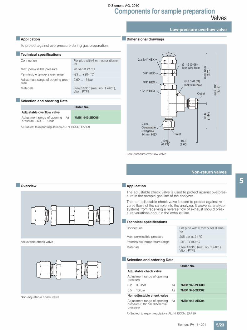
Components for sample preparationValves
Low-pressure overflow valve
5/23Siemens PA 11 · 2011
5
■ Application
To protect against overpressure during gas preparation.
■ Technical specifications
■ Selection and ordering Data
A) Subject to export regulations AL: N, ECCN: EAR99
■ Dimensional drawings
Low-pressure overflow valve
■ Overview
Adjustable check valve
Non-adjustable check valve
■ Application
The adjustable check valve is used to protect against overpres-sure in the sample gas line of the analyzer.
The non-adjustable check valve is used to protect against re-verse flows of the sample into the analyzer. It prevents analyzer systems from receiving a reverse flow of exhaust should pres-sure variations occur in the exhaust line.
■ Technical specifications
■ Selection and ordering Data
A) Subject to export regulations AL: N, ECCN: EAR99
Connection For pipe with 6 mm outer diame-ter
Max. permissible pressure 20 bar at 21 °C
Permissible temperature range -23 ... +204 °C
Adjustment range of opening pres-sure
0.69 ... 15 bar
Materials Steel SS316 (mat. no. 1.4401), Viton, PTFE
Order No.
Adjustable overflow valve
Adjustment range of opening pressure 0.69 ... 15 bar
A) 7MB1 943-2EC06
Inlet
Outlet
Ø 1.5 (0.06)
Ø 2.3 (0.09)
10.9 (0.43)
40.6 (1.60)
36.6
(1
.44)
max
. 105
(4
.14)
max
. 68.
6 (2
.70)
lock wire hole
lock wire hole
Gaugeable Swagelok 14 mm HEX
2 x 3/4“ HEX
3/4“ HEX
3/4“ HEX
13/16“ HEX
2 x 6
Connection For pipe with 6 mm outer diame-ter
Max. permissible pressure 205 bar at 21 °C
Permissible temperature range -25 ... +190 °C
Materials Steel SS316 (mat. no. 1.4401), Viton, PTFE
Order No.
Adjustable check valve
Adjustment range of opening pressure
0.2 ... 3.5 bar A) 7MB1 943-2EC00
3.5 ... 10 bar A) 7MB1 943-2EC02
Non-adjustable check valve
Adjustment range of opening pressure 0.02 bar differential pressure
A) 7MB1 943-2EC04
Non-return valves
© Siemens AG, 2010

Components for sample preparationValves
Shut-off ball valve for low temperatures
5/24 Siemens PA 11 · 2011
5
■ Application
The shut-off ball valve is used to shut off the flow of sample gas.
■ Design
Gas-tight at both high and low operating pressures, Teflon gas-ket fills out the hollow space and prevents accumulation of con-tamination.
■ Technical specifications
Note
On delivery, the shut-off ball valves are set for a pressure of 70 bar. At higher pressures, it may be necessary to tighten the packing further (1/8 rotation is sufficient).
■ Selection and ordering Data
A) Subject to export regulations AL: N, ECCN: EAR99
Zubehör
A supporting sleeve is required for each gas duct when using a Teflon hose 4 x 6.
A) Subject to export regulations AL: N, ECCN: EAR99
■ Dimensional drawings
Shut-off ball valve, dimensions and valve positions
■ Application
The shut-off ball valve is used to shut off the flow of sample gas.
■ Technical specifications
■ Selection and ordering Data
A) Subject to export regulations AL: N, ECCN: EAR99
■ Dimensional drawings
Shut-off ball valve
Material
• Body, ball system X 10 CrNiMoTi 18 10, mat. no. 1.4401
• Handle Nylon, black
• Gasket Teflon
Permissible ambient and sample gas temperature
10 ... 65 °C
Max. permissible operating pres-sure at 21 °C
175 bar
Connection For pipe with 6 mm outer diame-ter
Weight Approx. 0.3 kg
Order No.
Shut-off ball valve A) 7MB1 943-2BA20
With 3.2 mm bore
Order No.
Stainless steel supporting sleeve
For hose 4/6 A) 7MB1 943-2DA10
For hose 6/8 A) 7MB1 943-6AB01
Open
Closed14.3
29
29
97
34
2957
Materials
• Ball Stainless steel SS316 (mat. no. 1.4401)
• Packing ring PEEK
• Packing Reinforced PTFE
Max. temperature 235 °C
Max. pressure
• At -29 … +38 °C 151 bar
• At 235 °C 7 bar
Connection For pipe with 6 mm outer diame-ter
Order No.
Shut-off ball valve A) 7MB1 943-2EA02
Shut-off ball valve for high temperatures
© Siemens AG, 2010
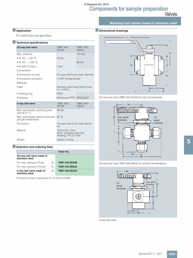
Components for sample preparationValves
Multiway ball valves made of stainless steel
5/25Siemens PA 11 · 2011
5
■ Application
For switching over gas flows.
■ Technical specifications
■ Selection and ordering Data
A) Subject to export regulations AL: N, ECCN: EAR99
■ Dimensional drawings
3/2-way ball valve 7MB1 943-2EA08 for high temperatures
3/2-way ball valve 7MB1 943-2BA22 for ambient temperatures
5-way ball valve
3/2-way ball valve 7MB1 943-2EA08
7MB1 943-2BA22
Max. pressure 175 bar
• At -30 ... +40 °C 70 bar
• At -55 ... +150 °C 68 bar
• At 235 °C (max.) 7 bar
Connections
• Connection on side For pipe with 6 mm outer diameter
• Connection at bottom ¼ NPT, female thread
Materials
• Ball Stainless steel body SS316 (mat. no. 1.4401)
• Packing ring PEEK –
• Packing Reinforced PTFE PFA/D3307
5-way ball valve 7MB1 943-2EA08
7MB1 943-2BA22
Max. permissible operating pres-sure at 21 °C
68 bar
Max. permissible ambient and sam-ple gas temperature
65 °C
Connection For pipe with 6 mm outer diame-ter
Material Twist knob: nylonBody: stainless steel 316Packing: TFE ID 1760
Weight Approx. 0.3 kg
Order No.
3/2-way ball valve made of stainless steel
For max. pressure 70 bar A) 7MB1 943-2EA08
For max. pressure 210 bar A) 7MB1 943-2BA22
5-way ball valve made of stainless steel
A) 7MB1 943-2EA20
6max. panel thickness
15panel borehole
29
28
34
927
56
4 max. panel thickness23
panel borehole
39
2039
2211
43
© Siemens AG, 2010

Components for sample preparationValves
Control assemblies for shut-off ball valves
5/26 Siemens PA 11 · 2011
5
■ Application
The control assembly is required to pneumatically open and close the respective ball valve.
Control assembly 7MB1 943-2EA00
By applying a control medium with a specific inlet pressure, the ball valve is opened or closed depending on the mode of opera-tion.
Spring reset in the unpressurized state.
Control assembly 7MB1 943-2EA10
By applying a control medium with a specific inlet pressure, the position of the ball valve is moved through 180°. Application: e.g. switching over from sample gas to calibration/zero gas.
Spring reset in the unpressurized state.
■ Dimensional drawings
Control assembly for shut-off ball valve
■ Technical specifications
■ Selection and ordering Data
A) Subject to export regulations AL: N, ECCN: EAR99
Accessories
A) Subject to export regulations AL: N, ECCN: EAR99
■ Application
To shut off and switch over gases. Also suitable for highly corro-sive gases.
■ Technical specifications
1) 140 °C on request
■ Selection and ordering Data
■ Dimensional drawings
Shut-off ball valve 3-way and 5-way ball valves
Spring return (125)Double pressure (104)
Mounting boreholes
125
1/8" NTP
10432
8 37
9
45
Min. control pressure 3.5 bar
Max. control pressure
• 7MB1 943-2EA00 13.5 bar
• 7MB1 943-2EA10 13.5 bar
Permissible temperature -30 ... +95 °C
Connection ¼NPT, female thread
Order No.
Control assembly for shut-off ball valve
For max. control pressure of 13.5 bar
• Swivel range 90° A) 7MB1 943-2EA00
• Swivel range 180° A) 7MB1 943-2EA10
Order No.
Mounting set for ball valve
For control assembly 7MB1 943-2EA00
• Ball valve 7MB1 943-2EA02 A) 7MB1 943-2EA04
• Ball valve 7MB1 943-2BA20 A) 7MB1 943-2EA06
For control assembly 7MB1 943-2EA10
• Ball valve 7MB1 943-2EA08 A) 7MB1 943-2EA04
• Ball valve 7MB1 943-2BA22 A) 7MB1 943-2EA06
Gas connection Screw-in fitting G¼
Nominal diameter 4 mm
Permissible operating overpressure 10 bar
Max. permissible sample temperature 140 °C
Max. permissible ambient temperature 90 °C1)
Material of parts wetted by the sample gas
Polyvinylfluoride (PVDF) / Viton
Type of mounting With mounting clamp
Order No.
Shut-off ball valve made of PVDFWith mounting clamps
7MB1 943-2BA25
3-way ball valve made of PVDFWith mounting clamps
7MB1 943-2BA30
5-way ball valve made of PVDFWith mounting clamp
7MB1 943-2BA35
Spacer for wall mountingfor 5-way ball valve
7MB1 943-2BA40
Male coupling G¼ made of PVDFFor Teflon hose with 6 mm outer diame-ter
see „Fittings/Fittings made of PVDF”“
Shut-off and multiway ball valves made of PVDF
© Siemens AG, 2010

Components for sample preparationSolenoid valves
2/2-way solenoid valveMade of PVDF
5/27Siemens PA 11 · 2011
5
■ Technical specifications
■ Selection and ordering Data
1) 2 screw-in fittings are also required (not included in scope of delivery)
Accessories
■ Dimensional drawings
2/2-way solenoid valve 24/230 V made of PVDF, with appliance socket
Brief characteristics • Hinged armature valve with ma-nual override
• Direct-acting with seal dia-phragm
• Suitable for a wide range of ag-gressive media
Permissible pressure range
• With 230 V AC power supply 0 ... 4 bar above atmospheric pressure
• With 24 V DC power supply 0 ... 2 bar above atmospheric pressure
Nominal diameter 4 mm
Seal material Kalrez (FFKM, perfluoro elasto-mer)
Gas connection G 3/8 female thread
Electric connection Appliance socket with LED and varistor (not included in scope of delivery)
Degree of protection acc. to EN 60529
IP65
Installation position Any
Power supply 230 V AC, 50 Hz, 40 VA (startup), 8 VA (operation) or 24 V DC, 8 W (operation)
Principle of operation Closed when deenergized
Ambient temperature Max. +50 °C
Weight Approx. 0.32 kg
Order No.
2/2-way solenoid valve made of PVDF1)
Power supply 230 V AC, 50 Hz 7MB1 943-2BA50
Power supply 24 V DC 7MB1 943-2BA55
Order No.
Appliance socket acc. to DIN EN 175301-803, form A, with LED and varistor
For 12 … 24 V AC/DC 7MB1 943-2BB20
For 200 … 240 V AC/DC 7MB1 943-2BB22
M4 / 5 deep
top view bottom view
G 3
/829
4670
91
21
3
35 24
38
© Siemens AG, 2010
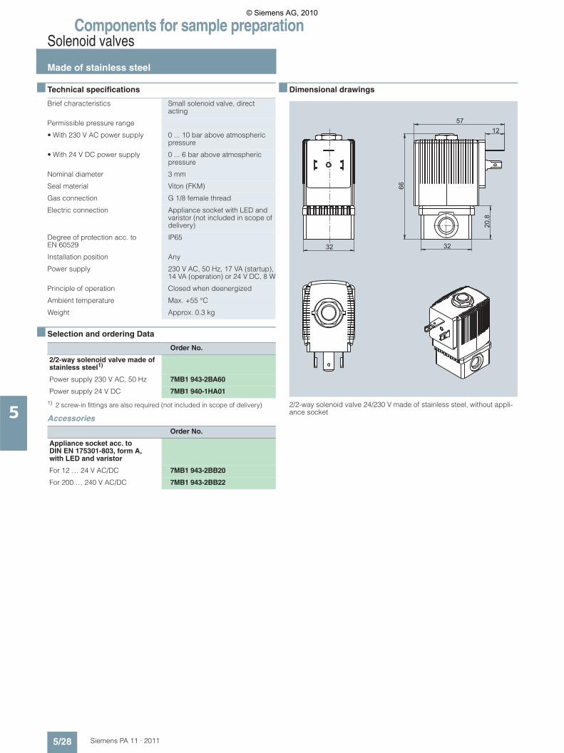
Components for sample preparationSolenoid valves
Made of stainless steel
5/28 Siemens PA 11 · 2011
5
■ Technical specifications
■ Selection and ordering Data
1) 2 screw-in fittings are also required (not included in scope of delivery)
Accessories
■ Dimensional drawings
2/2-way solenoid valve 24/230 V made of stainless steel, without appli-ance socket
Brief characteristics Small solenoid valve, direct acting
Permissible pressure range
• With 230 V AC power supply 0 ... 10 bar above atmospheric pressure
• With 24 V DC power supply 0 ... 6 bar above atmospheric pressure
Nominal diameter 3 mm
Seal material Viton (FKM)
Gas connection G 1/8 female thread
Electric connection Appliance socket with LED and varistor (not included in scope of delivery)
Degree of protection acc. to EN 60529
IP65
Installation position Any
Power supply 230 V AC, 50 Hz, 17 VA (startup), 14 VA (operation) or 24 V DC, 8 W
Principle of operation Closed when deenergized
Ambient temperature Max. +55 °C
Weight Approx. 0.3 kg
Order No.
2/2-way solenoid valve made of stainless steel1)
Power supply 230 V AC, 50 Hz 7MB1 943-2BA60
Power supply 24 V DC 7MB1 940-1HA01
Order No.
Appliance socket acc. to DIN EN 175301-803, form A, with LED and varistor
For 12 … 24 V AC/DC 7MB1 943-2BB20
For 200 … 240 V AC/DC 7MB1 943-2BB2220
.8
32
1257
66
32
© Siemens AG, 2010

Components for sample preparationSolenoid valves
Made of stainless steel, explosion-proof
5/29Siemens PA 11 · 2011
5
■ Technical specifications
■ Selection and ordering Data
1) 2 screw-in fittings are also required (not included in scope of delivery).
Accessories
■ Dimensional drawings
2/2-way solenoid valve made of stainless steel, explosion-proof
Brief characteristics 2/2-way small solenoid valve, direct acting
Permissible pressure range 0 ... 10 bar above atmospheric pressure
Nominal diameter 2 mm
Enclosure material Stainless steel mat. no. 1.4305
Seal material Viton (FKM)
Gas connection G 1/4 female thread
Electric connection Explosion-proof terminal box with M 20 x 1.5 cable gland, without fuse (fuse available as acces-sory)
Degree of protection acc. to EN 60529
IP65
Installation position Any, preferably with operating mechanism upwards
Power supply 230 V AC, 50 Hz, 9 VA (operation) or 24 V DC, 9 W
Coil size 40 mm
ATEX approval and device identifi-cation
• PTB 00 ATEX 2129 X• II 2G EEx em II T4• II 2D IP65 T=135 °C
Principle of operation Closed when deenergized
Ambient temperature -30 °C … +60 °C
Weight Approx. 0.74 kg
Order No.
2/2-way solenoid valve made of stainless steel, explosion-proof1)
Power supply 230 V AC, 50 Hz 7MB1 943-2BA86
Power supply 24 V DC 7MB1 943-2BA87
Order No.
Medium-slow device fuse for explosion-proof solenoid valves, for fitting in the terminal box, for coil rating 9 W
100 mA fuse for power supply 230 V AC, 50 Hz
7MB1 943-2BA91
1 A fuse for power supply 24 V DC 7MB1 943-2BA92
Nur
spa
nnun
gsfre
i öffn
en
disc
onne
ct fr
om th
e su
pply
circ
uit b
efor
e se
rvic
ing
© Siemens AG, 2010
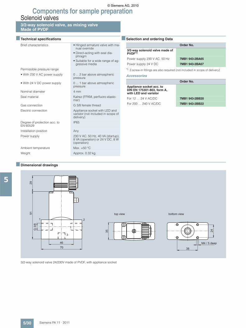
Components for sample preparationSolenoid valves3/2-way solenoid valve, as mixing valveMade of PVDF
5/30 Siemens PA 11 · 2011
5
■ Technical specifications
■ Selection and ordering Data
1) 3 screw-in fittings are also required (not included in scope of delivery)
Accessories
■ Dimensional drawings
3/2-way solenoid valve 24/230V made of PVDF, with appliance socket
Brief characteristics • Hinged armature valve with ma-nual override
• Direct-acting with seal dia-phragm
• Suitable for a wide range of ag-gressive media
Permissible pressure range
• With 230 V AC power supply 0 ... 2 bar above atmospheric pressure
• With 24 V DC power supply 0 ... 1 bar above atmospheric pressure
Nominal diameter 4 mm
Seal material Kalrez (FFKM, perfluoro elasto-mer)
Gas connection G 3/8 female thread
Electric connection Appliance socket with LED and varistor (not included in scope of delivery)
Degree of protection acc. to EN 60529
IP65
Installation position Any
Power supply 230 V AC, 50 Hz, 40 VA (startup), 8 VA (operation) or 24 V DC, 8 W (operation)
Ambient temperature Max. +50 °C
Weight Approx. 0.32 kg
Order No.
3/2-way solenoid valve made of PVDF1)
Power supply 230 V AC, 50 Hz 7MB1 943-2BA65
Power supply 24 V DC 7MB1 943-2BA67
Order No.
Appliance socket acc. to DIN EN 175301-803, form A, with LED and varistor
For 12 … 24 V AC/DC 7MB1 943-2BB20
For 200 … 240 V AC/DC 7MB1 943-2BB22
M4 / 5 deep
top view bottom view
G 3
/829
4670
91
21
3
35 24
38
© Siemens AG, 2010
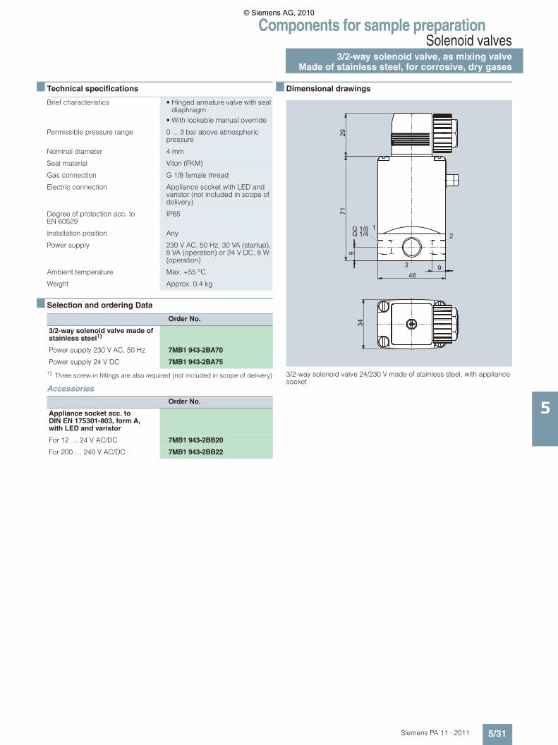
Components for sample preparationSolenoid valves
3/2-way solenoid valve, as mixing valveMade of stainless steel, for corrosive, dry gases
5/31Siemens PA 11 · 2011
5
■ Technical specifications
■ Selection and ordering Data
1) Three screw-in fittings are also required (not included in scope of delivery)
Accessories
■ Dimensional drawings
3/2-way solenoid valve 24/230 V made of stainless steel, with appliance socket
Brief characteristics • Hinged armature valve with seal diaphragm
• With lockable manual override
Permissible pressure range 0 ... 3 bar above atmospheric pressure
Nominal diameter 4 mm
Seal material Viton (FKM)
Gas connection G 1/8 female thread
Electric connection Appliance socket with LED and varistor (not included in scope of delivery)
Degree of protection acc. to EN 60529
IP65
Installation position Any
Power supply 230 V AC, 50 Hz, 30 VA (startup), 8 VA (operation) or 24 V DC, 8 W (operation)
Ambient temperature Max. +55 °C
Weight Approx. 0.4 kg
Order No.
3/2-way solenoid valve made of stainless steel1)
Power supply 230 V AC, 50 Hz 7MB1 943-2BA70
Power supply 24 V DC 7MB1 943-2BA75
Order No.
Appliance socket acc. to DIN EN 175301-803, form A, with LED and varistor
For 12 … 24 V AC/DC 7MB1 943-2BB20
For 200 … 240 V AC/DC 7MB1 943-2BB22
9
9
2971
46
G 1/8G 1/4
34
21
3
© Siemens AG, 2010

Components for sample preparationSolenoid valves3/2-way solenoid valve, as mixing valveMade of stainless steel, explosion-proof
5/32 Siemens PA 11 · 2011
5
■ Technical specifications
■ Selection and ordering Data
1) 2 screw-in fittings are also required (not included in scope of delivery)
Accessories
■ Dimensional drawings
3/2-way solenoid valve made of stainless steel, explosion-proof
Brief characteristics 3/2-way small solenoid valve, direct acting
Permissible pressure range 0 ... 7 bar above atmospheric pressure
Nominal diameter 1.5 mm
Enclosure material Stainless steel mat. no. 1.4305
Seal material Viton (FKM)
Gas connection G 1/4 female thread
Electric connection Explosion-proof terminal box with M 20 x 1.5 cable gland, without fuse (fuse available as acces-sory)
Degree of protection acc. to EN 60529
IP65
Installation position Any, preferably with operating mechanism upwards
Power supply 230 V AC, 50 Hz, 9 VA (operation) or 24 V DC, 9 W
Coil size 40 mm
ATEX approval and device identifi-cation
• PTB 00 ATEX 2129 X• II 2G EEx em II T4• II 2D IP65 T=135 °C
Principle of operation 3/2-way, for universal use
Ambient temperature -30 … +60 °C
Weight Approx. 0.74 kg
Order No.
3/2-way solenoid valve made of stainless steel, explosion-proof1)
Power supply 230 V AC, 50 Hz 7MB1 943-2BA88
Power supply 24 V DC 7MB1 943-2BA90
Order No.
Medium-slow device fuse for explosion-proof solenoid valves, for fitting in the terminal box, for coil rating 9 W
100 mA fuse for power supply 230 V AC, 50 Hz
7MB1 943-2BA91
1 A fuse for power supply 24 V DC 7MB1 943-2BA92
Nur
spa
nnun
gsfre
i öffn
en
disc
onne
ct fr
om th
e su
pply
circ
uit b
efor
e se
rvic
ing
© Siemens AG, 2010

Components for sample preparationSolenoid valves
Appliance socket acc. to DIN EN 175301-803,form A, with LED and varistor
5/33Siemens PA 11 · 2011
5
■ Technical specifications
■ Selection and ordering Data
■ Dimensional drawings
Appliance socket acc. to DIN EN 175301-803, form A
Material
• Enclosure Polycarbonate
• Contacts Brass, silver-plated
Max. continuous temperature 90 °C
Cable diameter 6 ... 7 mm
Number of poles 2 pins + PE conductor
Electric connection Terminals, max. 1.5 mm²
Seal between coil and socket Flat gasket 1.5 mm
Degree of protection acc. to EN 60529
IP65
Status display LED, red
Order No.
Appliance socket acc. to DIN EN 175301-803, form A
For 12 … 24 V AC/DC, max. 6 A 7MB1 943-2BB20
For 200 … 240 V AC/DC, max. 6 A 7MB1 943-2BB22
1.5
27.5
18
18
46
M3
28
28
© Siemens AG, 2010
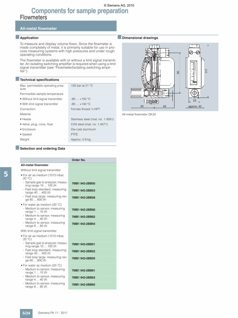
Components for sample preparationFlowmeters
All-metal flowmeter
5/34 Siemens PA 11 · 2011
5
■ Application
To measure and display volume flows. Since the flowmeter is made completely of metal, it is primarily suitable for use in pro-cess measuring systems with high pressures and under rough operating conditions.
The flowmeter is available with or without a limit signal transmit-ter. An isolating switching amplifier is required when using a limit signal transmitter (see “Flowmeter/Isolating switching ampli-fier”).
■ Technical specifications
■ Selection and ordering Data
■ Dimensional drawings
All-metal flowmeter DK32
Max. permissible operating pres-sure
130 bar at 21 °C
Permissible sample temperature
• Without limit signal transmitter -80 ... +150 °C
• With limit signal transmitter -80 ... +140 °C
Connection Female thread ¼ NPT
Material
• Heads Stainless steel (mat. no. 1.4581)
• Valve, plug, cone, float CrNi steel (mat. no. 1.4571)
• Enclosure Die-cast aluminum
• Gasket PTFE
Weight Approx. 0.9 kg
Order No.
All-metal flowmeter
Without limit signal transmitter
• For air as medium (1013 mbar, 20 °C)- Sample gas to analyzer, measu-
ring range 10 ... 100 l/h7MB1 943-2BB50
- Fast loop standard, measuring range 40 ... 400 l/h
7MB1 943-2BB53
- Fast loop large, measuring ran-ge 80 ... 800 l/h
7MB1 943-2BB58
• For water as medium (20 °C)- Medium to sensor, measuring
range 1 ... 10 l/h7MB1 943-2BB60
- Medium to sensor, measuring range 4 ... 40 l/h
7MB1 943-2BB62
- Medium to sensor, measuring range 8 ... 80 l/h
7MB1 943-2BB64
With limit signal transmitter
• For air as medium (1013 mbar, 20 °C)- Sample gas to analyzer, measu-
ring range 10 ... 100 l/h7MB1 943-2BB51
- Fast loop standard, measuring range 40 ... 400 l/h
7MB1 943-2BB52
- Fast loop large, measuring ran-ge 80 ... 800 l/h
7MB1 943-2BB55
• For water as medium (20 °C)- Medium to sensor, measuring
range 1 ... 10 l/h7MB1 943-2BB61
- Medium to sensor, measuring range 4 ... 40 l/h
7MB1 943-2BB63
- Medium to sensor, measuring range 8 ... 80 l/h
7MB1 943-2BB65
approx. 4255 45
25
117
90
© Siemens AG, 2010

Components for sample preparationFlowmeters
Glass flowmeter
5/35Siemens PA 11 · 2011
5
■ Application
To measure and display volume flows. The flowmeter version with PEEK float is also suitable for corrosive gases.
The flowmeter works according to the variable-area measuring principle and therefore does not cause a delay in indication.
The flow is adjusted using a precision valve.
The flowmeter is available with or without a limit signal transmit-ter. An isolating switching amplifier is required when using a limit signal transmitter (see “Flowmeter/Isolating switching ampli-fier”).
■ Technical specifications
■ Selection and ordering Data
Accessories
2 male couplings, G¼ female thread, may also be required, see „Fittings/Fittings made of PVDF“.
■ Dimensional drawings
Flowmeter DK 800
Flowmeter
Measuring range 10 ... 100 l gas/h
Materials
• Heads PVDF
• Cone Borosilicate glass
• Float- 7MB1 943-2BB30/35 Stainless steel (mat. No. 1.4401)- 7MB1 943-2BB31/36 PEEK
• Gasket Viton
Gas connection G¼ female thread
Max. permissible operating pres-sure
6 bar
Weight Approx. 0.4 kg
Limit signal transmitter
Rated voltage 8 V DC
Current consumption
• Active area free 3 mA
• Active area covered 1 mA
Inherent inductance 170 �H
Inherent capacitance 90 nF
Permissible ambient temperature -25 ... +100 °C
Degree of protection to EN 60529 IP67
Order No.
Flowmeter
Measuring range 10 … 100 l/h
• Without limit signal transmitter 7MB1 943-2BB30
• With limit signal transmitter 7MB1 943-2BB35
Flowmeter for corrosive gases
Measuring range 10 … 100 l/h
• Without limit signal transmitter 7MB1 943-2BB31
• With limit signal transmitter 7MB1 943-2BB36
Adjustable limit signal transmitter
with limit signal transmitterwithout limit signal transmitter
22.5
Ø 4
.3
42G1/4
≈ 82 28 Pg11
80Ø
16
125
145
28
125
≈ 22
1
© Siemens AG, 2010
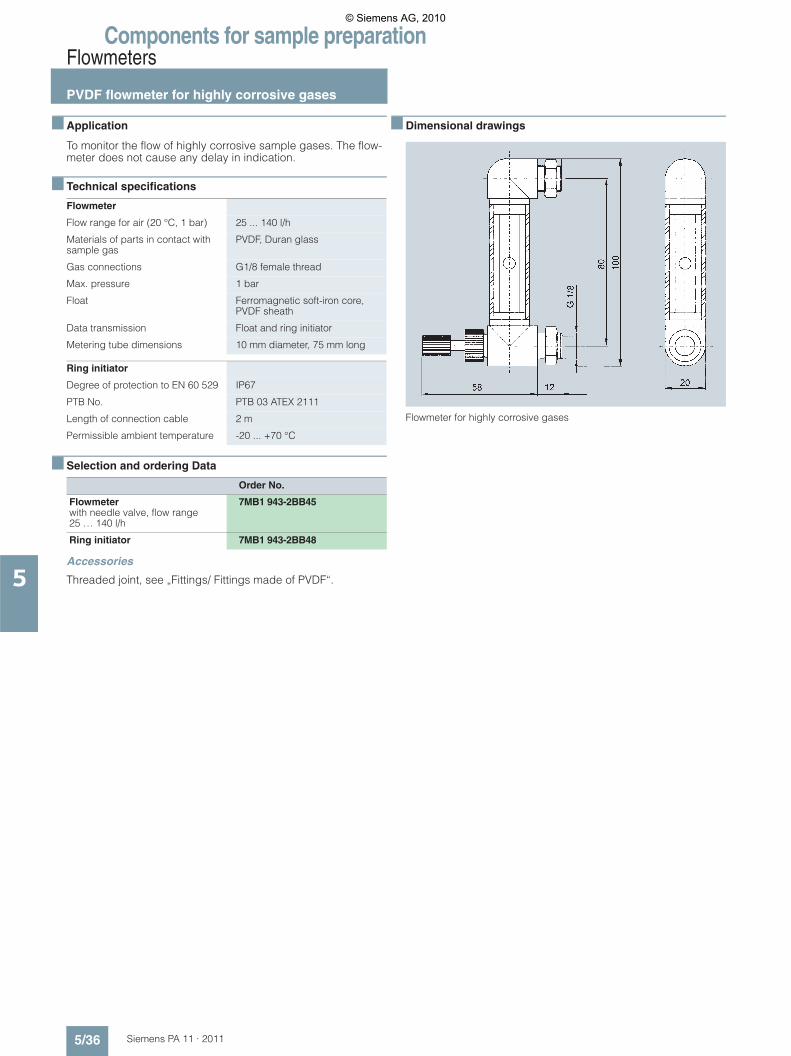
Components for sample preparationFlowmeters
PVDF flowmeter for highly corrosive gases
5/36 Siemens PA 11 · 2011
5
■ Application
To monitor the flow of highly corrosive sample gases. The flow-meter does not cause any delay in indication.
■ Technical specifications
■ Selection and ordering Data
Accessories
Threaded joint, see „Fittings/ Fittings made of PVDF“.
■ Dimensional drawings
Flowmeter for highly corrosive gases
Flowmeter
Flow range for air (20 °C, 1 bar) 25 ... 140 l/h
Materials of parts in contact with sample gas
PVDF, Duran glass
Gas connections G1/8 female thread
Max. pressure 1 bar
Float Ferromagnetic soft-iron core, PVDF sheath
Data transmission Float and ring initiator
Metering tube dimensions 10 mm diameter, 75 mm long
Ring initiator
Degree of protection to EN 60 529 IP67
PTB No. PTB 03 ATEX 2111
Length of connection cable 2 m
Permissible ambient temperature -20 ... +70 °C
Order No.
Flowmeterwith needle valve, flow range 25 … 140 l/h
7MB1 943-2BB45
Ring initiator 7MB1 943-2BB48
© Siemens AG, 2010

Components for sample preparationFlowmeters
Isolating switch amplifier
5/37Siemens PA 11 · 2011
5
■ Overview
Isolating switching amplifier, front view
■ Application
• Inputs (intrinsically-safe) acc. to DIN EN 60947-5-6 (NAMUR) or mechanical contacts
• Control circuits EEx ia IIC• Reversible direction of control action• Signal outputs (not intrinsically-safe) with changeover contact
max. 253 V AC / 2 A• EMC according to EN 61326, NAMUR NE 21• Electrical isolation according to EN 50020
■ Technical specifications
■ Selection and ordering Data
Accessories
2 male couplings, G¼ female thread, may also be required, see „Fittings/Fittings made of PVDF“.
■ Schematics
Isolating switching amplifier, schematic diagram (1 channel)
Switching capacity Signal outputs (not intrinsically-safe) with changeover contact max. 253 V; 2 A
Ambient temperature -20 ... +60 °C
Dimensions (L x W x H) in mm 120 x 20 x 115 (DIN rail moun-ting)
Degree of protection Control circuit EEx ia IIC
Weight Approx. 0.15 kg
Order No.
Isolating switching amplifier
24 V DC
• 1-channel 7MB1 943-2BB41
• 2-channel 7MB1 943-2BB42
230 V AC, 45 … 65 Hz
• 1-channel 7MB1 943-2BB43
• 2-channel 7MB1 943-2BB44
115 V AC, 45 … 65 Hz
• 1-channel 7MB1 943-2BB46
• 2-channel 7MB1 943-2BB47
Input EEx ia IIC
haza
rdou
s ar
eano
n ha
zard
ous
area
Output Power supply
yellow
© Siemens AG, 2010

Components for sample preparationPressure reducersSingle-stage pressure reducerFor calibration gas cylinders
5/38 Siemens PA 11 · 2011
5
■ Overview
Single-stage pressure reducer for N2 or O2 and for calibration gases for connection to gas cylinders
■ Application
For use with OXYMAT gas analyzers for reference gases N2 and O2. Chromium-plated brass enclosure. The single-stage pres-sure reducer is also available in a stainless steel version for cor-rosive calibration gases. For connection to gas cylinders.
Version with contact manometer on the high-pressure side
Electric signal when a minimum pressure is reached allows early replacement of gas cylinder.
■ Technical specifications
■ Selection and ordering Data
Accessories
An isolating switching amplifier is required to use the inductive contact (see "Flowmeters/isolating switching amplifier").
Single-stage pressure reducer for connection to gas cylinders
Gas connection, outlet Threaded joint for pipe with 6 mm outer diameter (clamping ring connection)
Inlet pressure Max. 200 bar
Outlet pressure range 0.5 ... 4 bar
Temperature range -20 ... +70 °C
Contact manometer
Type of contact Inductive contact, isolating switch amplifier required
ATEX identification of inductive con-tact sensor
II 2 G EEx ia IIC T6
Connecting cable length Approx. 1 m
Order No.
Single-stage pressure reducer for connection to gas cylinders
For N2, DIN 477 No. 10, brass 7MB1 943-1PB01-2AB3
For O2, DIN 477 No. 9, brass 7MB1 943-1PB01-2AB5
For calibration gas, DIN 477 No. 14, stainless steel
7MB1 943-1PA01-2AB6
For calibration gas, DIN 477 No. 14, stainless steel, with inductive contact manometer
7MB1 943-1PA01-2AC6
© Siemens AG, 2010

Components for sample preparationPressure reducers
Single-stage pressure reducerFor installation in pipes
5/39Siemens PA 11 · 2011
5
■ Overview
Single-stage pressure reducer for installation in pipes
■ Application
For corrosive gases (stainless steel enclosure) or non-corrosive gases (chromium-plated brass enclosure). For installation in pipes.
■ Technical specifications
■ Selection and ordering Data
Single-stage pressure reducer for installation in pipes
Gas connection, inlet and outlet 1/4" NPT
Inlet pressure (outlet pressure cont-roller)
Max. 241 bar
Outlet pressure range (outlet pres-sure controller)
0.1 ... 1.7 bar or 0.1 ... 7 bar
Inlet pressure (inlet pressure cont-roller)
Corresponds to pressure control range
Inlet pressure range (inlet pressure controller)
0 ... 1.7 bar
Temperature range -26 ... +80 °C
Order No.
Single-stage pressure reducer for installation in pipes
Outlet pressure range 0.1 … 1.7 bar (outlet pressure controller)
• For corrosive gases; material: stainless steel
7MB1 943-1MA01-1CB1
• For corrosive gases and high temperatures up to 150 °C; material: stainless steel
7MB1 943-1MA01-1EB1
• For non-corrosive gases; material: chromium-plated brass
7MB1 943-1MB01-1CB1
Outlet pressure range 0.1 … 7 bar (outlet pressure controller)
• For corrosive gases; material: stainless steel
7MB1 943-1MA01-3CB1
• For non-corrosive gases; material: chromium-plated brass
7MB1 943-1MB01-3CB1
Inlet pressure range 0 … 1.7 bar (inlet pressure controller)
• For corrosive gases; material: stainless steel
7MB1 943-1TA01-1CB1
© Siemens AG, 2010
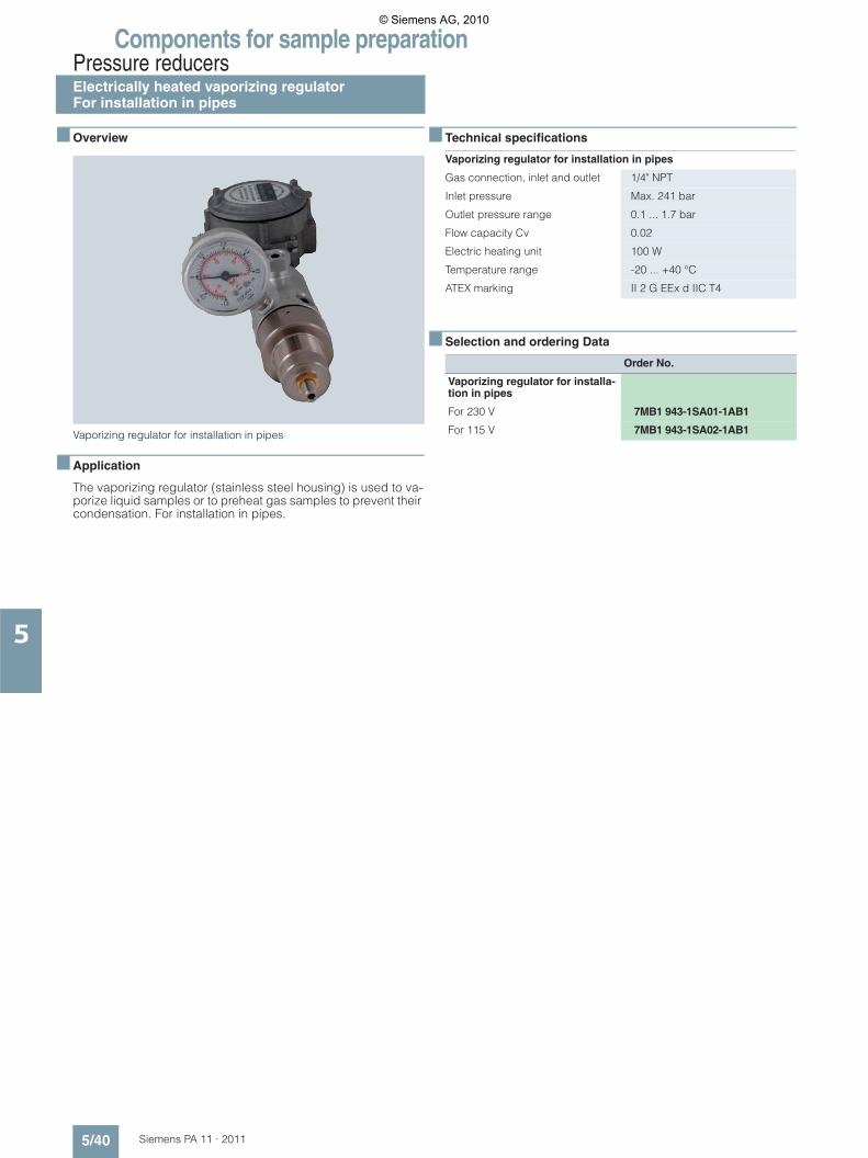
Components for sample preparationPressure reducersElectrically heated vaporizing regulatorFor installation in pipes
5/40 Siemens PA 11 · 2011
5
■ Overview
Vaporizing regulator for installation in pipes
■ Application
The vaporizing regulator (stainless steel housing) is used to va-porize liquid samples or to preheat gas samples to prevent their condensation. For installation in pipes.
■ Technical specifications
■ Selection and ordering Data
Vaporizing regulator for installation in pipes
Gas connection, inlet and outlet 1/4" NPT
Inlet pressure Max. 241 bar
Outlet pressure range 0.1 ... 1.7 bar
Flow capacity Cv 0.02
Electric heating unit 100 W
Temperature range -20 ... +40 °C
ATEX marking II 2 G EEx d IIC T4
Order No.
Vaporizing regulator for installa-tion in pipes
For 230 V 7MB1 943-1SA01-1AB1
For 115 V 7MB1 943-1SA02-1AB1
© Siemens AG, 2010
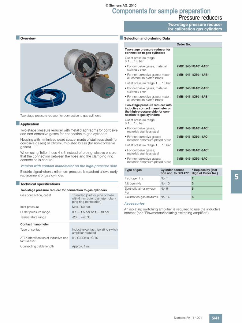
Components for sample preparationPressure reducers
Two-stage pressure reducerfor calibration gas cylinders
5/41Siemens PA 11 · 2011
5
■ Overview
Two-stage pressure reducer for connection to gas cylinders
■ Application
Two-stage pressure reducer with metal diaphragms for corrosive and non-corrosive gases for connection to gas cylinders.
Housing with minimized dead space, made of stainless steel (for corrosive gases) or chromium-plated brass (for non-corrosive gases).
When using Teflon hose 4 x 6 instead of piping, always ensure that the connection between the hose and the clamping ring connection is secure.
Version with contact manometer on the high-pressure side
Electric signal when a minimum pressure is reached allows early replacement of gas cylinder.
■ Technical specifications
■ Selection and ordering Data
Accessories
An isolating switching amplifier is required to use the inductive contact (see "Flowmeters/isolating switching amplifier").
Two-stage pressure reducer for connection to gas cylinders
Gas connection, outlet Threaded joint for pipe or hose with 6 mm outer diameter (clam-ping ring connection)
Inlet pressure Max. 200 bar
Outlet pressure range 0.1 ... 1.5 bar or 1 ... 10 bar
Temperature range -20 ... +70 °C
Contact manometer
Type of contact Inductive contact, isolating switch amplifier required
ATEX identification of inductive con-tact sensor
II 2 G EEx ia IIC T6
Connecting cable length Approx. 1 m
Order No.
Two-stage pressure reducer for connection to gas cylinders
Outlet pressure range 0.1 … 1.5 bar
• For corrosive gases; material: stainless steel
7MB1 943-1QA01-1AB*
• For non-corrosive gases; materi-al: chromium-plated brass
7MB1 943-1QB01-1AB*
Outlet pressure range 1 … 10 bar
• For corrosive gases; material: stainless steel
7MB1 943-1QA01-3AB*
• For non-corrosive gases; materi-al: chromium-plated brass
7MB1 943-1QB01-3AB*
Two-stage pressure reducer with inductive contact manometer on the high-pressure side for con-nection to gas cylinders
Outlet pressure range 0.1 … 1.5 bar
• For corrosive gases; material: stainless steel
7MB1 943-1QA01-1AC*
• For non-corrosive gases; material: chromium-plated brass
7MB1 943-1QB01-1AC*
Outlet pressure range 1 … 10 bar
• For corrosive gases; material: stainless steel
7MB1 943-1QA01-3AC*
• For non-corrosive gases; material: chromium-plated brass
7MB1 943-1QB01-3AC*
Type of gas Cylinder connec-tion acc. to DIN 477
* Replace by (last digit of Order No.)
Hydrogen H2 No. 1 2
Nitrogen N2 No. 10 3
Synthetic air or oxygen O2
No. 9 5
Calibration gas mixtures No. 14 6
© Siemens AG, 2010

Components for sample preparationPressure reducersTwin cylinder stationfor two calibration gas cylinders
5/42 Siemens PA 11 · 2011
5
■ Overview
Twin cylinder station for two calibration gas cylinders
■ Application
Two-stage cylinder station with automatic switchover for connec-tion of two gas cylinders; stainless steel or nickel-plated brass construction.
When using Teflon hose 4 x 6 instead of piping, always ensure that the connection between the hose and the clamping ring connection is secure.
Version with contact manometer on the high-pressure side
Electric signal when a minimum pressure is reached allows early replacement of gas cylinder.
■ Technical specifications
■ Selection and ordering Data
Accessories
Two connection shafts are required per cylinder station to con-nect the latter to the gas cylinders, approved for max. 200 bar.
An isolating switching amplifier is required to use the inductive contact (see "Flowmeters/isolating switching amplifier").
Two-stage cylinder station for connection of two gas cylinders
Gas connection, outlet Threaded joint for pipe or hose with 6 mm outer diameter (clam-ping ring connection)
Inlet pressure Max. 200 bar
Outlet pressure range 5 ... 17 bar
Temperature range -20 ... +70 °C
Contact manometer
Type of contact Inductive contact, isolating switch amplifier required
ATEX identification of inductive con-tact sensor
II 2 G EEx ia IIC T6
Connecting cable length Approx. 1 m
Order No.
Two-stage cylinder station for connection of two gas cylinders
Without contact manometer
� With stainless steel enclosure 7MB1 943-1RA01-4AB7
� With nickel plated brass enclo-sure
7MB1 943-1RB01-4AB7
With contact manometer on the high-pressure side
� With stainless steel enclosure 7MB1 943-1RA01-4AC7
� With nickel plated brass enclo-sure
7MB1 943-1RB01-4AC7
Type of gas Cylinder connection acc. to DIN 477
Order No.
Hydrogen H2 No. 1 7MB1 943-1UA01-4AA2
Nitrogen N2 No. 10 7MB1 943-1UA01-4AA3
Helium He No. 6 7MB1 943-1UA01-4AA4
© Siemens AG, 2010
Components for sample preparationGases
Calibration gases
5/43Siemens PA 11 · 2011
5
■ Technical specifications
1) Referred to component concentration2) Exceptions are possible
■ Selection and ordering Data
Cylinder body Steel, seamless, or aluminum alloy
Connection thread acc. to DIN 477 O2 above 21 vol.%
M19 x 1.5 left-hand, No. 14, DIN 477, No. 9
Filling pressure
Standard 150 bar
With CO2 > 17% and SF6 > 6.2%
< 150 bar
Tolerance Component concentration
Manufacturer’s tolerance1)
Analytical accuracy1)
• 1 ... 99 ppm ± 10 % ± 2 ... ± 5 %
• 100 ... 999 ppm ± 5 % ± 2 %
• 0.1 ... 4.9 % ± 2 % ± 2 %
• 5 ... 50 % ± 1 % ± 1 %
Cylinder identification
Stamped identification According to TRG 102
Analysis certificate Under cylinder cap
Item no. On cylinder shoulder
Cylinder color According to European standard DIN EN 1089-3
Cylinder body Shoulder
• Inert gases Blue Bright green
• Oxidizing gases Blue2) Light blue
• Flammable gases Blue Red
• Toxic gases Blue Yellow
Storage temperature
Winter delivery -10 ... +40 ºC
Summer delivery +10 ... +40 ºC
Before use, the calibration gases must be left for at least 24 h to ensure the right temperature and homogenization.TestIn accordance with transport regulations (GGVS) and pressurized con-tainer regulations (TRG 102), pressurized containers must be regularly tested by an approved expert.
Dimensions (including cap)
10-l steel cylinder Diameter 140 mm, length approx. 1 000 mm
10-l aluminum cylinder Diameter 140 mm, length approx. 1 100 mm
Weight (empty, including cap)
10-l steel cylinder Approx. 20 kg
10-l aluminum cylinder Approx. 12 kg
Order No.
10-l cylinder with one calibration gas component in residual gas N2with certificate
Calibration gas
• CO > 10 vpm 7MB1 943-5AA00
• NO > 100 vpm 7MB1 943-5AA01
> 20 vpm 7MB1 943-5AA02
• SO2 > 100 vpm 7MB1 943-5AA03
> 10 vpm 7MB1 943-5AA04
• O2 < 21 % 7MB1 943-5AA05
> 21 % 7MB1 943-5AA26
• CO2 < 17 % 7MB1 943-5AA06
> 17 % 7MB1 943-5AA07
• H2 % v/v 7MB1 943-5AA08
• SF6 > 100 vpm 7MB1 943-5AA28
• SF6 > 6.2 % 7MB1 943-5AA10
• C3H8 > 10 < 100 vpm 7MB1 943-5AA27
• CH4 < 5 % 7MB1 943-5AA31
Calibration gas concentrationSpecify in plain text
Concentration ... vpm or ... % or ... mg/m³
10-l cylinder with two calibration gas components in residual gas N2with certificate
Calibration gas compo-nent 1
Calibration gas component 2
CO > 10 vpm O2 < 21 % 7MB1 943-5AA11
CO > 10 vpm NO > 100 vpm 7MB1 943-5AA12
CO > 10 vpm CO2 < 17 % 7MB1 943-5AA13
CO2 > 17 % 7MB1 943-5AA14
CO > 10 vpm SO2 > 100 vpm 7MB1 943-5AA15
SO2 > 10 vpm 7MB1 943-5AA16
SO2 > 100 vpm O2 < 21 % 7MB1 943-5AA17
> 10 vpm 7MB1 943-5AA18
SO2 > 100 vpm NO > 100 vpm 7MB1 943-5AA30
Calibration gas concentrationSpecify in plain text
Calibration gas component 1 Concentration ... vpm
Calibration gas component 2 Concentration ... vpm or ... % or ... mg/m³
10-l cylinder with three calibration gas components in residual gas N2
with certificate
Calib. gas comp. 1
Calib. gas comp. 2
Calib. gas comp. 3
CO > 10 vpm CO2 < 17 % O2 < 21 % 7MB1 943-5AA20
CO2 > 17 % 7MB1 943-5AA21
CO > 10 vpm SO2 > 100 vpm
O2 < 21 % 7MB1 943-5AA22
CO > 10 vpm CO2 < 17 % H2 7MB1 943-5AA23
CO2 > 17 % 7MB1 943-5AA24
CO > 10 vpm NO > 100 vpm SO2 > 100 vpm 7MB1 943-5AA25
Calibration gas concentration specify in plain text
Calibration gas component 1 Concentration ... vpm
Calibration gas component 2 Concentration ... vpm or ... %
Calibration gas component 3 Concentration ... vpm or ... % or ... mg/m³
Further designs
Special labeling of cylinder Specify in plain text: (max. 10 characters, e.g. owner’s name)
……….
© Siemens AG, 2010
Components for sample preparationGases
Pure gases
5/44 Siemens PA 11 · 2011
5
■ Technical specifications
1) Exceptions are possible
■ Selection and ordering Data
A) Subject to export regulations AL: N, ECCN: EAR99
Cylinder body Steel, seamless
Max. filling pressure 200 bar
Cylinder identification
Stamped identification According to TRG 101
Identification of con-tents
On cylinder shoulder (with purity data)
Item no. On cylinder shoulder
TÜV marking Stamped on cylinder
Cylinder color According to European standard DIN EN 1089-3
Cylinder body Shoulder
• Hydrogen Red Red
• Nitrogen Gray Black
• Oxygen Blue1) White
• Synthetic air White1) White with black ring
Storage temperature -20 ... +50 ºC
Test In accordance with transport regulations (GGVS) and pressurized container regulations (TRG 101), pressurized containers for pure gases must be regularly tested by an appro-ved expert.
Dimensions (including cap)
10-l cylinder Diameter 140 mm, length approx. 1 000 mm
50-l cylinder Diameter 230 mm, length approx. 1 700 mm
Weight
10-l cylinder Approx. 16 kg
50-l cylinder Approx. 70 kg
Pure gas Purity Connection thread acc. to DIN 477
Cylinder size Order No.
Hydrogen H2 5.0 W 21.80 x 1/14 left-hand 10 l 7MB1 943-5AB00
5.0 (No. 1) 50 l 7MB1 943-5AB02
Nitrogen N2 4.6 W 24.32 x 1/14 right-hand 10 l 7MB1 943-5AB04
5.0 (No. 10) 10 l 7MB1 943-5AB05
4.6 50 l 7MB1 943-5AB06
5.0 50 l A) 7MB1 943-5AB07
Oxygen O2 5.0 R ¾ right-hand (No. 9) 50 l A) 7MB1 943-5AB11
Synthetic air CnHm < 0.1 vpm R ¾ right-hand (No. 9) 10 l A) 7MB1 943-5AB08
50 l 7MB1 943-5AB10
Special labeling
Specify in plain text: (max. 10 charac-ters, e.g. owner’s name)
……….
© Siemens AG, 2010
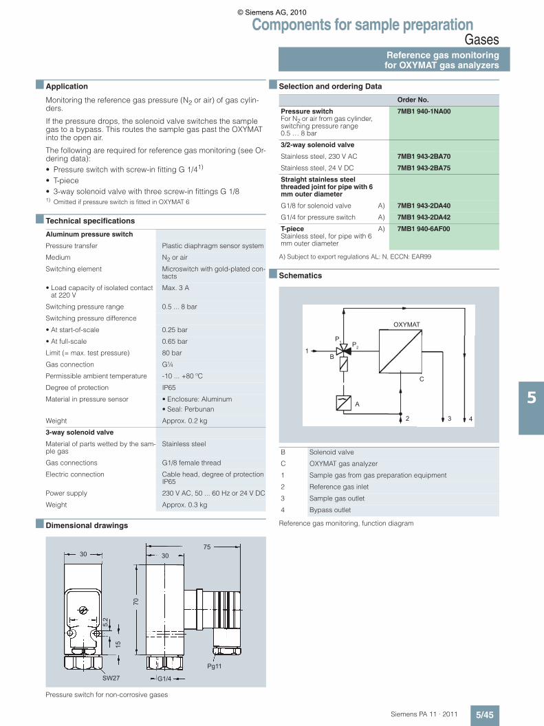
Components for sample preparationGases
Reference gas monitoringfor OXYMAT gas analyzers
5/45Siemens PA 11 · 2011
5
■ Application
Monitoring the reference gas pressure (N2 or air) of gas cylin-ders.
If the pressure drops, the solenoid valve switches the sample gas to a bypass. This routes the sample gas past the OXYMAT into the open air.
The following are required for reference gas monitoring (see Or-dering data):• Pressure switch with screw-in fitting G 1/41)
• T-piece• 3-way solenoid valve with three screw-in fittings G 1/81) Omitted if pressure switch is fitted in OXYMAT 6
■ Technical specifications
■ Dimensional drawings
Pressure switch for non-corrosive gases
■ Selection and ordering Data
A) Subject to export regulations AL: N, ECCN: EAR99
■ Schematics
Reference gas monitoring, function diagram
Aluminum pressure switch
Pressure transfer Plastic diaphragm sensor system
Medium N2 or air
Switching element Microswitch with gold-plated con-tacts
• Load capacity of isolated contact at 220 V
Max. 3 A
Switching pressure range 0.5 ... 8 bar
Switching pressure difference
• At start-of-scale 0.25 bar
• At full-scale 0.65 bar
Limit (= max. test pressure) 80 bar
Gas connection G¼
Permissible ambient temperature -10 ... +80 ºC
Degree of protection IP65
Material in pressure sensor • Enclosure: Aluminum• Seal: Perbunan
Weight Approx. 0.2 kg
3-way solenoid valve
Material of parts wetted by the sam-ple gas
Stainless steel
Gas connections G1/8 female thread
Electric connection Cable head, degree of protection IP65
Power supply 230 V AC, 50 ... 60 Hz or 24 V DC
Weight Approx. 0.3 kg
5.2
15
70
3075
30
SW27 G1/4
Pg11
Order No.
Pressure switchFor N2 or air from gas cylinder, switching pressure range 0.5 … 8 bar
7MB1 940-1NA00
3/2-way solenoid valve
Stainless steel, 230 V AC 7MB1 943-2BA70
Stainless steel, 24 V DC 7MB1 943-2BA75
Straight stainless steel threaded joint for pipe with 6 mm outer diameter
G1/8 for solenoid valve A) 7MB1 943-2DA40
G1/4 for pressure switch A) 7MB1 943-2DA42
T-pieceStainless steel, for pipe with 6 mm outer diameter
A) 7MB1 940-6AF00
B Solenoid valve
C OXYMAT gas analyzer
1 Sample gas from gas preparation equipment
2 Reference gas inlet
3 Sample gas outlet
4 Bypass outlet
1
OXYMAT
432
C
A
B
P1 P2
© Siemens AG, 2010
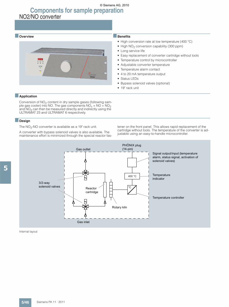
Components for sample preparationNO2/NO converter
5/46 Siemens PA 11 · 2011
5
■ Overview
■ Benefits
• High conversion rate at low temperature (400 °C)• High NO2 conversion capability (300 ppm)• Long service life• Easy replacement of converter cartridge without tools• Temperature control by microcontroller• Adjustable converter temperature• Temperature alarm contact• 4 to 20 mA temperature output• Status LEDs• Bypass solenoid valves (optional)• 19" rack unit
■ Application
Conversion of NO2 content in dry sample gases (following sam-ple gas cooler) into NO. The gas components NOx = NO + NO2 and NO2 can then be measured directly and indirectly using the ULTRAMAT 23 and ULTRAMAT 6 respectively.
■ Design
The NO2-NO converter is available as a 19" rack unit.
A converter with bypass solenoid valves is also available. The maintenance effort is minimized through the special reactor fas-
tener on the front panel. This allows rapid replacement of the cartridge without tools. The temperature of the converter is ad-justable using an easy-to-handle microcontroller.
Internal layout
400 °C
°C
© Siemens AG, 2010
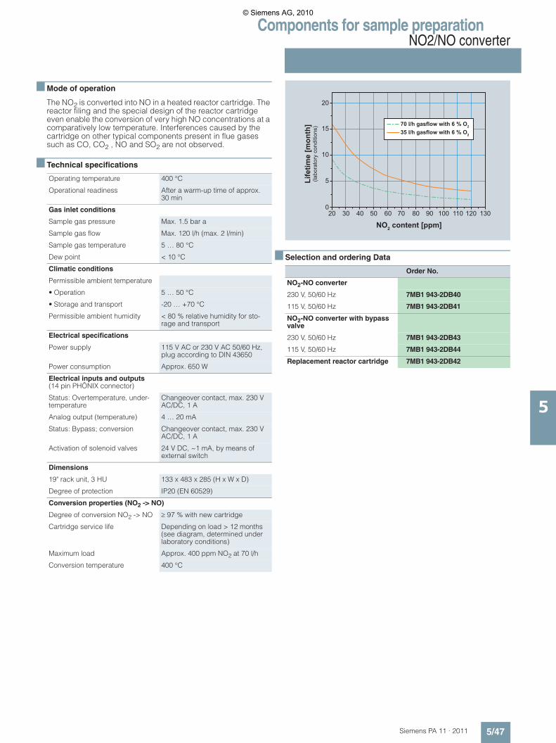
Components for sample preparationNO2/NO converter
5/47Siemens PA 11 · 2011
5
■ Mode of operation
The NO2 is converted into NO in a heated reactor cartridge. The reactor filing and the special design of the reactor cartridge even enable the conversion of very high NO concentrations at a comparatively low temperature. Interferences caused by the cartridge on other typical components present in flue gases such as CO, CO2 , NO and SO2 are not observed.
■ Technical specifications
■ Selection and ordering Data
Operating temperature 400 °C
Operational readiness After a warm-up time of approx. 30 min
Gas inlet conditions
Sample gas pressure Max. 1.5 bar a
Sample gas flow Max. 120 l/h (max. 2 l/min)
Sample gas temperature 5 … 80 °C
Dew point < 10 °C
Climatic conditions
Permissible ambient temperature
• Operation 5 … 50 °C
• Storage and transport -20 … +70 °C
Permissible ambient humidity < 80 % relative humidity for sto-rage and transport
Electrical specifications
Power supply 115 V AC or 230 V AC 50/60 Hz, plug according to DIN 43650
Power consumption Approx. 650 W
Electrical inputs and outputs(14 pin PHÖNIX connector)
Status: Overtemperature, under-temperature
Changeover contact, max. 230 V AC/DC, 1 A
Analog output (temperature) 4 … 20 mA
Status: Bypass; conversion Changeover contact, max. 230 V AC/DC, 1 A
Activation of solenoid valves 24 V DC, ~1 mA, by means of external switch
Dimensions
19" rack unit, 3 HU 133 x 483 x 285 (H x W x D)
Degree of protection IP20 (EN 60529)
Conversion properties (NO2 -> NO)
Degree of conversion NO2 -> NO � 97 % with new cartridge
Cartridge service life Depending on load > 12 months (see diagram, determined under laboratory conditions)
Maximum load Approx. 400 ppm NO2 at 70 l/h
Conversion temperature 400 °C
Order No.
NO2-NO converter
230 V, 50/60 Hz 7MB1 943-2DB40
115 V, 50/60 Hz 7MB1 943-2DB41
NO2-NO converter with bypass valve
230 V, 50/60 Hz 7MB1 943-2DB43
115 V, 50/60 Hz 7MB1 943-2DB44
Replacement reactor cartridge 7MB1 943-2DB42
70 l/h gasflow with 6 % O2
35 l/h gasflow with 6 % O2
Life
time
[mon
th]
(labo
rato
ry c
ondi
tions
)
NO2 content [ppm]
20
20 30 40 50 60 70 80 90 100 110 120 130
15
10
5
0
© Siemens AG, 2010
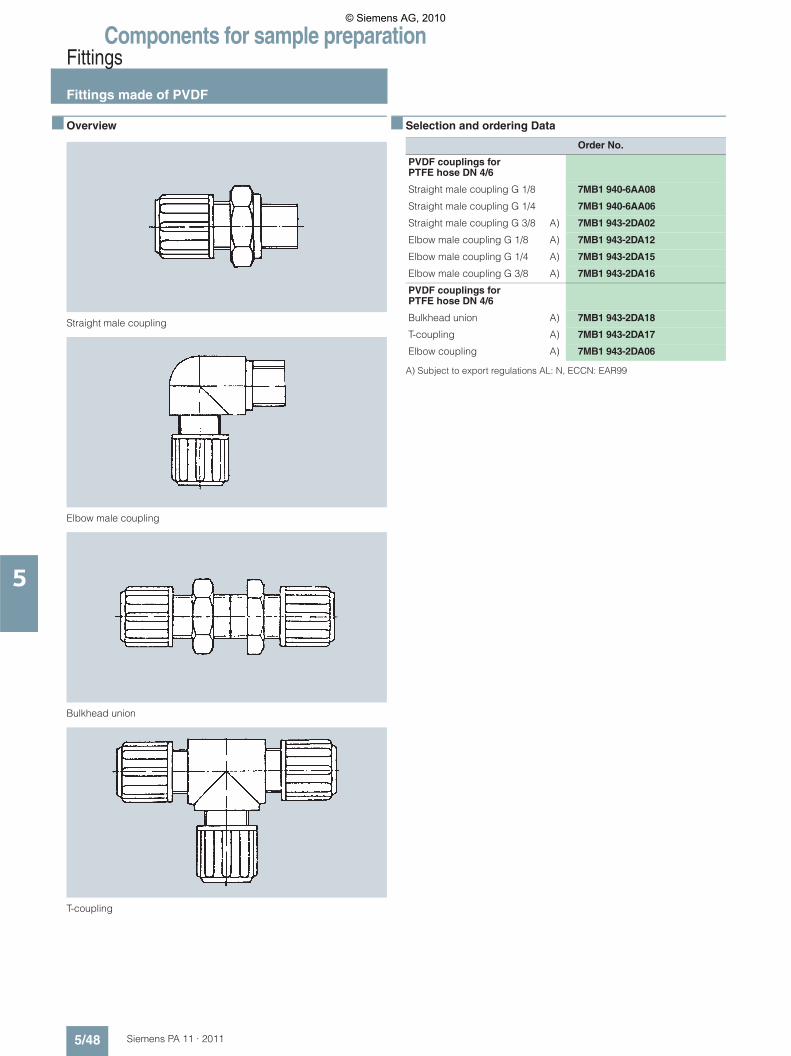
Components for sample preparationFittings
Fittings made of PVDF
5/48 Siemens PA 11 · 2011
5
■ Overview
Straight male coupling
Elbow male coupling
Bulkhead union
T-coupling
■ Selection and ordering Data
A) Subject to export regulations AL: N, ECCN: EAR99
Order No.
PVDF couplings for PTFE hose DN 4/6
Straight male coupling G 1/8 7MB1 940-6AA08
Straight male coupling G 1/4 7MB1 940-6AA06
Straight male coupling G 3/8 A) 7MB1 943-2DA02
Elbow male coupling G 1/8 A) 7MB1 943-2DA12
Elbow male coupling G 1/4 A) 7MB1 943-2DA15
Elbow male coupling G 3/8 A) 7MB1 943-2DA16
PVDF couplings for PTFE hose DN 4/6
Bulkhead union A) 7MB1 943-2DA18
T-coupling A) 7MB1 943-2DA17
Elbow coupling A) 7MB1 943-2DA06
© Siemens AG, 2010
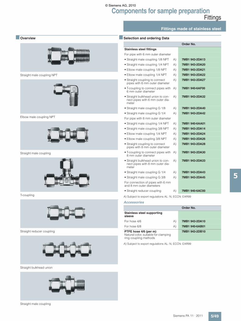
Components for sample preparationFittings
Fittings made of stainless steel
5/49Siemens PA 11 · 2011
5
■ Overview
Straight male coupling NPT
Elbow male coupling NPT
Straight male coupling
T-coupling
Straight reducer coupling
Straight bulkhead union
Straight male coupling
■ Selection and ordering Data
A) Subject to export regulations AL: N, ECCN: EAR99
Accessories
A) Subject to export regulations AL: N, ECCN: EAR99
Order No.
Stainless steel fittings
For pipe with 6 mm outer diameter
• Straight male coupling 1/8 NPT A) 7MB1 943-2DA13
• Straight male coupling 1/4 NPT A) 7MB1 943-2DA20
• Elbow male coupling 1/8 NPT A) 7MB1 943-2DA21
• Elbow male coupling 1/4 NPT A) 7MB1 943-2DA22
• Straight coupling to connect pipes with 6 mm outer diameter
A) 7MB1 943-2DA27
• T-coupling to connect pipes with 6 mm outer diameter
A) 7MB1 940-6AF00
• Straight bulkhead union to con-nect pipes with 6 mm outer dia-meter
A) 7MB1 943-2DA32
• Straight male coupling G 1/8 A) 7MB1 943-2DA40
• Straight male coupling G 1/4 A) 7MB1 943-2DA42
For pipe with 8 mm outer diameter
• Straight male coupling 1/4 NPT A) 7MB1 940-6AA01
• Straight male coupling 3/8 NPT A) 7MB1 943-2DA14
• Elbow male coupling 1/4 NPT A) 7MB1 943-2DA24
• Elbow male coupling 3/8 NPT A) 7MB1 943-2DA26
• Straight coupling to connect pipes with 8 mm outer diameter
A) 7MB1 943-2DA28
• T-coupling to connect pipes with 8 mm outer diameter
A) 7MB1 943-2DA30
• Straight bulkhead union to con-nect pipes with 8 mm outer dia-meter
A) 7MB1 943-2DA33
• Straight male coupling G 1/4 A) 7MB1 943-2DA43
• Straight male coupling G 3/8 A) 7MB1 943-2DA45
For connection of pipes with 6 mm and 8 mm outer diameters
• Straight reducer coupling A) 7MB1 940-6AC00
Order No.
Stainless steel supporting sleeve
For hose 4/6 A) 7MB1 943-2DA10
For hose 6/8 A) 7MB1 940-6AB01
PTFE hose 4/6 (per m)Natural color, suitable for clamping ring coupling methods
7MB1 943-2DB10
© Siemens AG, 2010
Components for sample preparation
Notes
5/50 Siemens PA 11 · 2011
5
■
© Siemens AG, 2010
Siemens PA 11 · 2011
66/2 Gas measuring and warning systems6/2 Sensors for explosive gases and vapors6/5 Sensors for monitoring threshold limit
values6/7 8022 evaluation unit and accessories
Measuring equipment
© Siemens AG, 2010
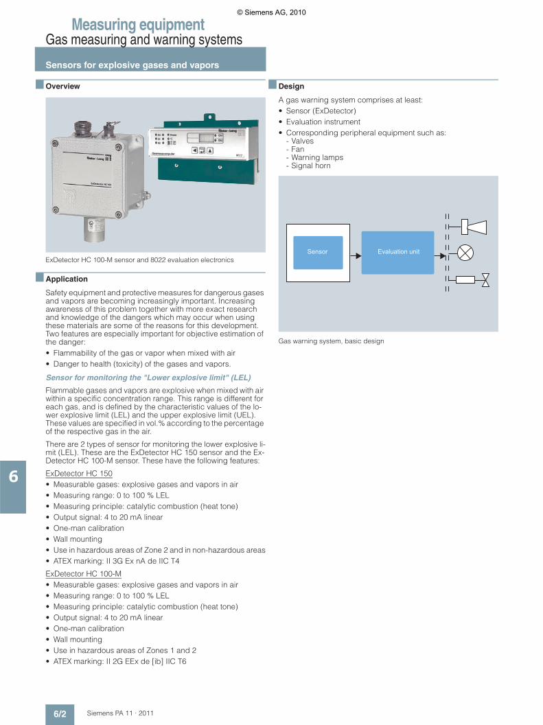
Measuring equipmentGas measuring and warning systems
Sensors for explosive gases and vapors
6/2 Siemens PA 11 · 2011
6
■ Overview
ExDetector HC 100-M sensor and 8022 evaluation electronics
■ Application
Safety equipment and protective measures for dangerous gases and vapors are becoming increasingly important. Increasing awareness of this problem together with more exact research and knowledge of the dangers which may occur when using these materials are some of the reasons for this development. Two features are especially important for objective estimation of the danger:• Flammability of the gas or vapor when mixed with air• Danger to health (toxicity) of the gases and vapors.
Sensor for monitoring the "Lower explosive limit" (LEL)
Flammable gases and vapors are explosive when mixed with air within a specific concentration range. This range is different for each gas, and is defined by the characteristic values of the lo-wer explosive limit (LEL) and the upper explosive limit (UEL). These values are specified in vol.% according to the percentage of the respective gas in the air.
There are 2 types of sensor for monitoring the lower explosive li-mit (LEL). These are the ExDetector HC 150 sensor and the Ex-Detector HC 100-M sensor. These have the following features:
ExDetector HC 150• Measurable gases: explosive gases and vapors in air• Measuring range: 0 to 100 % LEL• Measuring principle: catalytic combustion (heat tone)• Output signal: 4 to 20 mA linear• One-man calibration• Wall mounting• Use in hazardous areas of Zone 2 and in non-hazardous areas• ATEX marking: II 3G Ex nA de IIC T4
ExDetector HC 100-M• Measurable gases: explosive gases and vapors in air• Measuring range: 0 to 100 % LEL• Measuring principle: catalytic combustion (heat tone)• Output signal: 4 to 20 mA linear• One-man calibration• Wall mounting• Use in hazardous areas of Zones 1 and 2• ATEX marking: II 2G EEx de [ib] IIC T6
■ Design
A gas warning system comprises at least:• Sensor (ExDetector)• Evaluation instrument • Corresponding peripheral equipment such as:
- Valves- Fan- Warning lamps- Signal horn
Gas warning system, basic design
Sensor Evaluation unit
© Siemens AG, 2010
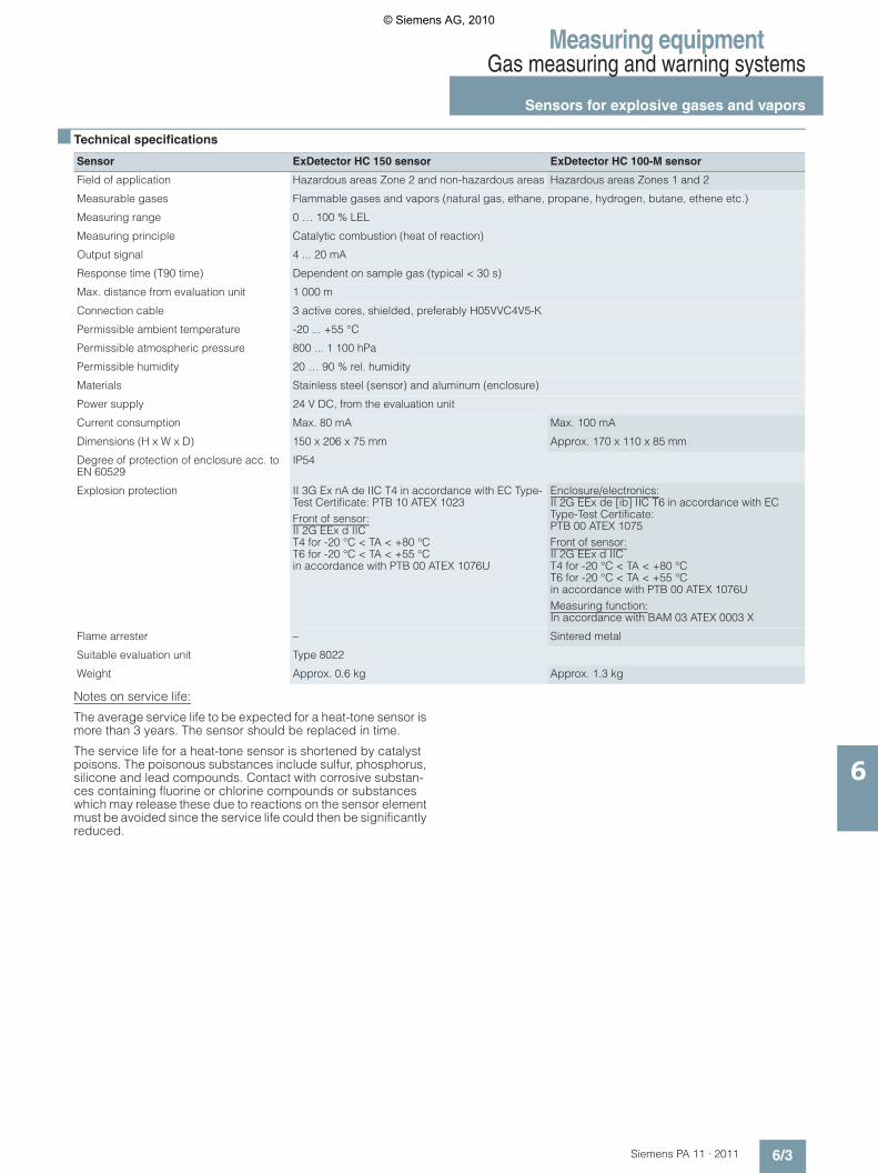
Measuring equipmentGas measuring and warning systems
Sensors for explosive gases and vapors
6/3Siemens PA 11 · 2011
6
■ Technical specifications
Notes on service life:
The average service life to be expected for a heat-tone sensor is more than 3 years. The sensor should be replaced in time.
The service life for a heat-tone sensor is shortened by catalyst poisons. The poisonous substances include sulfur, phosphorus, silicone and lead compounds. Contact with corrosive substan-ces containing fluorine or chlorine compounds or substances which may release these due to reactions on the sensor element must be avoided since the service life could then be significantly reduced.
Sensor ExDetector HC 150 sensor ExDetector HC 100-M sensor
Field of application Hazardous areas Zone 2 and non-hazardous areas Hazardous areas Zones 1 and 2
Measurable gases Flammable gases and vapors (natural gas, ethane, propane, hydrogen, butane, ethene etc.)
Measuring range 0 … 100 % LEL
Measuring principle Catalytic combustion (heat of reaction)
Output signal 4 ... 20 mA
Response time (T90 time) Dependent on sample gas (typical < 30 s)
Max. distance from evaluation unit 1 000 m
Connection cable 3 active cores, shielded, preferably H05VVC4V5-K
Permissible ambient temperature -20 ... +55 °C
Permissible atmospheric pressure 800 ... 1 100 hPa
Permissible humidity 20 … 90 % rel. humidity
Materials Stainless steel (sensor) and aluminum (enclosure)
Power supply 24 V DC, from the evaluation unit
Current consumption Max. 80 mA Max. 100 mA
Dimensions (H x W x D) 150 x 206 x 75 mm Approx. 170 x 110 x 85 mm
Degree of protection of enclosure acc. to EN 60529
IP54
Explosion protection II 3G Ex nA de IIC T4 in accordance with EC Type-Test Certificate: PTB 10 ATEX 1023Front of sensor: II 2G EEx d IICT4 for -20 °C < TA < +80 °CT6 for -20 °C < TA < +55 °Cin accordance with PTB 00 ATEX 1076U
Enclosure/electronics: II 2G EEx de [ib] IIC T6 in accordance with EC Type-Test Certificate:PTB 00 ATEX 1075Front of sensor: II 2G EEx d IICT4 for -20 °C < TA < +80 °CT6 for -20 °C < TA < +55 °Cin accordance with PTB 00 ATEX 1076UMeasuring function: In accordance with BAM 03 ATEX 0003 X
Flame arrester – Sintered metal
Suitable evaluation unit Type 8022
Weight Approx. 0.6 kg Approx. 1.3 kg
© Siemens AG, 2010

Measuring equipmentGas measuring and warning systems
Sensors for explosive gases and vapors
6/4 Siemens PA 11 · 2011
6
■ Selection and ordering Data
Order No.
Sensor for monitoring the lower explosive limit (LEL)
Type ExDetector HC 150 for Ex Zone 2 and for non-hazardous areas with initial adjustment by the manufacturer to the type of gas lis-ted below
• Hydrogen (H2) 7MB1 943-6EA18-0A
• Methane (CH4) 7MB1 943-6EA18-0B
• Ethane (C2H6) 7MB1 943-6EA18-0C
• Propane (C3H8) 7MB1 943-6EA18-0D
• Butane (C4H10) 7MB1 943-6EA18-0E
• n-Pentane (C5H12) 7MB1 943-6EA18-0F
• n-Hexane (C6H14) 7MB1 943-6EA18-0G
• n-Heptane (C7H16) 7MB1 943-6EA18-0H
• Ethene (ethylene, C2H4) 7MB1 943-6EA18-0J
• Ethine (acetylene, C2H2) 7MB1 943-6EA18-0K
• Other type of gas (specify in the order)
7MB1 943-6EA18-0L
Type ExDetector HC 100-M for hazardous areas of Zones 1 and 2 with initial adjustment by the manufacturer to the type of gas lis-ted below
• Hydrogen (H2) 7MB1 943-6EA16-0A
• Methane (CH4) 7MB1 943-6EA16-0B
• Ethane (C2H6) 7MB1 943-6EA16-0C
• Propane (C3H8) 7MB1 943-6EA16-0D
• Butane (C4H10) 7MB1 943-6EA16-0E
• n-Pentane (C5H12) 7MB1 943-6EA16-0F
• n-Hexane (C6H14) 7MB1 943-6EA16-0G
• n-Heptane (C7H16) 7MB1 943-6EA16-0H
• Ethene (ethylene, C2H4) 7MB1 943-6EA16-0J
• Ethine (acetylene, C2H2) 7MB1 943-6EA16-0K
• Other type of gas (specify in the order)
7MB1 943-6EA16-0L
Calibrationbox-i(only for ExDetector HC 100-M)Hand-held unit for calibration, approved for hazardous areas Zone 1 and Zone 2
7MB1 943-6EA17
Calibration gas set and calibra-tion gas cylinders
See "Gas measuring and warning systems/Sensors for monitoring threshold limit values"
© Siemens AG, 2010

Measuring equipmentGas measuring and warning systems
Sensors for monitoring threshold limit values
6/5Siemens PA 11 · 2011
6
■ Application
A recommended value for the alarm thresholds of gas warning systems is the TLV (threshold limit value). The TLV is the maxi-mum permissible concentration of gas, vapor or suspended ma-terial in air at the workplace that, according to current know-ledge, will not influence the health of employees or cause unreasonable irritation even in the event of repeated and long-term exposure, usually 8 hours per day, but under observation of an average 40-hour working week (with single-shift working).
■ Design
There are 2 types of sensor available for monitoring the threshold limit values of toxic gases and vapors, as well as an oxygen de-ficiency: the gas monitor TOX and the Ex-monitor TOX. These have the following features:
Gas monitor TOX• Measurable gases: O2, CO, H2S, Cl2, H2, HCN, SO2, NO,
NO2; further sensors for toxic gases on request• Measuring range: depends on type of gas (see Ordering data)• Measuring principle: electrochemical measuring cell• Output signal 4 to 20 mA• One-man calibration• 2-wire system
Ex-monitor TOX• Technical data as for gas monitor TOX, but for use in Ex Zones
1 and 2• Explosion-proof, II 2G EEx ia IIC T4• Concentration display
■ Dimensional drawings
Gas monitor TOX (left) and Ex-monitor TOX (right)
■ Technical specifications
Sensor Gas monitor TOX Ex-monitor TOX
Field of application Non-hazardous areas Hazardous areas of Zones 1 and 2
Measurable gases Toxic gases and vapors (see ordering data)
Measuring range See ordering data
Measuring principle Electrochemical measuring cell
Output signal 4 ... 20 mA
Max. distance from evaluation unit 1 000 m
Connection cable 2-core, shielded, max. line resistance 100 �/core
Recommended barriers – Transmitter power supply
Permissible ambient temperature -10 ... +50 °C
Permissible atmospheric pressure 900 ... 1 100 mbar
Influence of atmospheric pressure < 0.02 % of signal/mbar
Permissible humidity 15 ... 90 % rel. humidity
Enclosure material Aluminum Glass fiber-reinforced polyester
Dimensions (H x W x D) 170 x 64 x 34 mm 115 x 160 x 75 mm
Degree of protection acc. to EN 60529 IP54
Power supply 24 V DC, from the evaluation unit or from emergency power supply (option)
Current consumption Max. 100 mA
Explosion protection – II 2G EEx ia IIC T4in accordance with EC Type-Test CertificateBVS 03 ATEX E 384
Suitable evaluation unit Type 8022
Weight Approx. 0.4 kg Approx. 1.2 kg
© Siemens AG, 2010
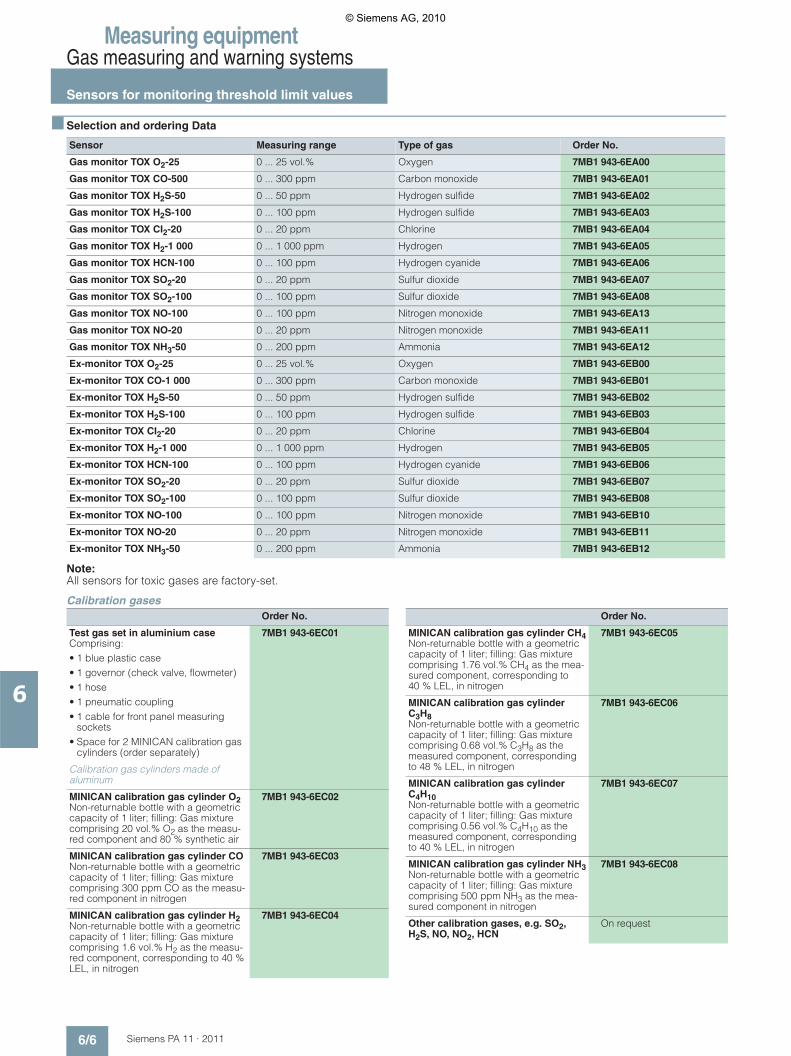
Measuring equipmentGas measuring and warning systems
Sensors for monitoring threshold limit values
6/6 Siemens PA 11 · 2011
6
■ Selection and ordering Data
Note: All sensors for toxic gases are factory-set.
Calibration gases
Sensor Measuring range Type of gas Order No.
Gas monitor TOX O2-25 0 ... 25 vol.% Oxygen 7MB1 943-6EA00
Gas monitor TOX CO-500 0 ... 300 ppm Carbon monoxide 7MB1 943-6EA01
Gas monitor TOX H2S-50 0 ... 50 ppm Hydrogen sulfide 7MB1 943-6EA02
Gas monitor TOX H2S-100 0 ... 100 ppm Hydrogen sulfide 7MB1 943-6EA03
Gas monitor TOX CI2-20 0 ... 20 ppm Chlorine 7MB1 943-6EA04
Gas monitor TOX H2-1 000 0 ... 1 000 ppm Hydrogen 7MB1 943-6EA05
Gas monitor TOX HCN-100 0 ... 100 ppm Hydrogen cyanide 7MB1 943-6EA06
Gas monitor TOX SO2-20 0 ... 20 ppm Sulfur dioxide 7MB1 943-6EA07
Gas monitor TOX SO2-100 0 ... 100 ppm Sulfur dioxide 7MB1 943-6EA08
Gas monitor TOX NO-100 0 ... 100 ppm Nitrogen monoxide 7MB1 943-6EA13
Gas monitor TOX NO-20 0 ... 20 ppm Nitrogen monoxide 7MB1 943-6EA11
Gas monitor TOX NH3-50 0 ... 200 ppm Ammonia 7MB1 943-6EA12
Ex-monitor TOX O2-25 0 ... 25 vol.% Oxygen 7MB1 943-6EB00
Ex-monitor TOX CO-1 000 0 ... 300 ppm Carbon monoxide 7MB1 943-6EB01
Ex-monitor TOX H2S-50 0 ... 50 ppm Hydrogen sulfide 7MB1 943-6EB02
Ex-monitor TOX H2S-100 0 ... 100 ppm Hydrogen sulfide 7MB1 943-6EB03
Ex-monitor TOX CI2-20 0 ... 20 ppm Chlorine 7MB1 943-6EB04
Ex-monitor TOX H2-1 000 0 ... 1 000 ppm Hydrogen 7MB1 943-6EB05
Ex-monitor TOX HCN-100 0 ... 100 ppm Hydrogen cyanide 7MB1 943-6EB06
Ex-monitor TOX SO2-20 0 ... 20 ppm Sulfur dioxide 7MB1 943-6EB07
Ex-monitor TOX SO2-100 0 ... 100 ppm Sulfur dioxide 7MB1 943-6EB08
Ex-monitor TOX NO-100 0 ... 100 ppm Nitrogen monoxide 7MB1 943-6EB10
Ex-monitor TOX NO-20 0 ... 20 ppm Nitrogen monoxide 7MB1 943-6EB11
Ex-monitor TOX NH3-50 0 ... 200 ppm Ammonia 7MB1 943-6EB12
Order No.
Test gas set in aluminium case Comprising: • 1 blue plastic case• 1 governor (check valve, flowmeter)• 1 hose• 1 pneumatic coupling• 1 cable for front panel measuring
sockets• Space for 2 MINICAN calibration gas
cylinders (order separately)
7MB1 943-6EC01
Calibration gas cylinders made of aluminum
MINICAN calibration gas cylinder O2Non-returnable bottle with a geometric capacity of 1 liter; filling: Gas mixture comprising 20 vol.% O2 as the measu-red component and 80 % synthetic air
7MB1 943-6EC02
MINICAN calibration gas cylinder CONon-returnable bottle with a geometric capacity of 1 liter; filling: Gas mixture comprising 300 ppm CO as the measu-red component in nitrogen
7MB1 943-6EC03
MINICAN calibration gas cylinder H2Non-returnable bottle with a geometric capacity of 1 liter; filling: Gas mixture comprising 1.6 vol.% H2 as the measu-red component, corresponding to 40 % LEL, in nitrogen
7MB1 943-6EC04
MINICAN calibration gas cylinder CH4Non-returnable bottle with a geometric capacity of 1 liter; filling: Gas mixture comprising 1.76 vol.% CH4 as the mea-sured component, corresponding to 40 % LEL, in nitrogen
7MB1 943-6EC05
MINICAN calibration gas cylinder C3H8Non-returnable bottle with a geometric capacity of 1 liter; filling: Gas mixture comprising 0.68 vol.% C3H8 as the measured component, corresponding to 48 % LEL, in nitrogen
7MB1 943-6EC06
MINICAN calibration gas cylinder C4H10Non-returnable bottle with a geometric capacity of 1 liter; filling: Gas mixture comprising 0.56 vol.% C4H10 as the measured component, corresponding to 40 % LEL, in nitrogen
7MB1 943-6EC07
MINICAN calibration gas cylinder NH3Non-returnable bottle with a geometric capacity of 1 liter; filling: Gas mixture comprising 500 ppm NH3 as the mea-sured component in nitrogen
7MB1 943-6EC08
Other calibration gases, e.g. SO2, H2S, NO, NO2, HCN
On request
Order No.
© Siemens AG, 2010

Measuring equipmentGas measuring and warning systems
8022 evaluation unit and accessories
6/7Siemens PA 11 · 2011
6
■ Application
The evaluation unit, when used together with sensors with a 4 to 20 mA mA signal output, has the following functions:• Measurement and display of gas concentration• Monitoring and warning of presence of these gases• Initiation of protective measures to counteract an increase in
the concentration.
The evaluation unit provides the operating voltage for the sen-sors and compares the sensor signal with the individual alarm thresholds. If the concentration rises above the set alarm threshold, this is visually indicated by lighting-up of the corres-ponding LED, and the associated relay contact is activated. The 8022 evaluation unit must not be installed in the hazardous area.
■ Technical specifications
■ Selection and ordering Data
Accessories
Evaluation unit
Number of connectable sensors 2
Type of sensor All sensors with output signal 4 ... 20 mA
Number of alarm thresholds 2 alarm stages adjustable for each sensor
Outputs (relay) • Alarm 1, non-latching (NC con-tact)
• Alarm 2, optionally latching (changeover contact)
• Horn (NC contact)• Fault (NO contact)
Output for recorder 0 ... 5 V, on front panel
Relay rating 230 V AC / 24 V DC; 2 A
Displays
• LEDs For operational readiness, alarm 1 and 2, horn and fault for each sensor
• Digital display For concentration, guidance through the menus and display of programming data
Control elements 3 buttons for• Horn and alarm reset• Guidance through menus• Programming
Warm-up period 30 min
Operating temperature 0 ... 55 °C
EC-Type Examination according to directive 94/9/EC
BVS 03 ATEX G 007 X
Enclosure
• Material Plastic
• Degree of protection acc. to EN 60529
IP30 or IP54 if installed in minia-ture field distributor (see Ordering data)
• Assembly Wall mounting or rail mounting (35 mm) with transparent pane and terminal cover
Electric connection 21-pin screw terminal
Power supply 210 ... 250 V AC, 50/60 Hz, 20 VA21.7 ... 28 V DC, 14 Wor110 V AC, 60 Hz, 20 VA21.7 ... 28 V DC, 14 W
Weight Approx. 0.75 kg
Emergency power supply with charger
Charger
• Design For mounting on a 35-mm rail (DIN), e.g. in miniature field distri-butors
• Degree of protection acc. to EN 60529
IP20
• Dimensions (H x W x D) in mm 96 x 105 x 56
• Weight Approx. 0.4 kg
Rechargeable battery
• Rated voltage 12 V
• Capacity 2.2 Ah
• Dimensions (H x W x D) in mm 66 x 177 x 34
• Weight Approx. 0.8 kg
Miniature field distributor
Degree of protection acc. to EN 60529
IP54
Dimensions (H x W x D) in mm
• Type KFV1 180 x 254 x 110
• Type KFV2 360 x 254 x 110
Order No.
8022 evaluation unitWith enclosure for wall mounting or for 35-mm rail mounting
• Power supply 230 V AC /24 V DC 7MB1 943-6EA30
• Power supply 110 V AC /24 V DC 7MB1 943-6EA35
Order No.
Emergency power supply with charger type NV 24Device for supply of 8022 evalua-tion unit with 24 V DC emergency power, with low-voltage check, comprising charger and 2 batte-ries 12 V/2.2 Ah
• Power supply 230 V AC 7MB1 943-6EA40
• Power supply 110 V AC 7MB1 943-6EA45
Spare battery1)
Rated voltage 12 V, capacity 2.2 Ah, dimensions (H x L x W) in mm: 66 x 177 x 34
7MB1 943-6EA60
Miniature field distributor KFV1To accommodate an 8022 evalua-tion unit, incl. installation and wiring
7MB1 943-6EA50
Miniature field distributor KFV2To accommodate 2 evaluation units 8022, incl. installation and wiring
7MB1 943-6EA55
Signal horn IP55For indoor and outdoor installation, with acoustic horn, approx. 108 dB (A), with impact-proof, thermoplas-tic (ABS) housing, gray
• Power supply 230 V AC, 50 Hz, 0.1 A
7MB1 943-6EA65
• Power supply 24 V DC, 0.45 A 7MB1 943-6EA66
© Siemens AG, 2010
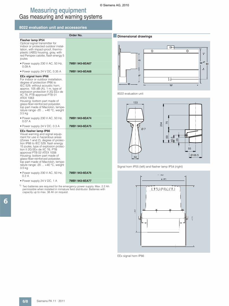
Measuring equipmentGas measuring and warning systems
8022 evaluation unit and accessories
6/8 Siemens PA 11 · 2011
6
1) Two batteries are required for the emergency power supply. Max. 2.2 Ah permissible when installed in miniature field distributor. Batteries with capacity up to max. 38 Ah on request.
■ Dimensional drawings
8022 evaluation unit
Signal horn IP55 (left) and flasher lamp IP54 (right)
EEx signal horn IP66
Flasher lamp IP54Optical signal transmitter for indoor or protected outdoor instal-lation, with impact-proof, thermo-plastic (ABS) housing, gray, with red Perspex calotte, flash energy 5 joules
• Power supply 230 V AC, 50 Hz, 0.09 A
7MB1 943-6EA67
• Power supply 24 V DC, 0.35 A 7MB1 943-6EA68
EEx signal horn IP66For indoor or outdoor installation, degree of protection IP66 to IEC 529, without acoustic horn, approx. 105 dB (A), 1 m, type of explosion protection II 2G EEx de IIC T6, PTB approval PTB 01 ATEX 1063Housing: bottom part made of glass-fiber-reinforced polyester, top part made of Macrolon, tempe-rature range -20 ... +40 °C, weight 3.5 kg
• Power supply 230 V AC, 50 Hz, 0.07 A
7MB1 943-6EA74
• Power supply 24 V DC, 0.3 A 7MB1 943-6EA75
EEx flasher lamp IP66Visual warning and signal equip-ment for use in hazardous areas (Zones 1 and 2), degree of protec-tion IP66 to IEC 529, flash energy 15 joules, type of explosion protec-tion II 2G EEx de IIC T6, PTB approval PTB 02 ATEX 1008Housing: bottom part made of glass-fiber-reinforced polyester, top part made of Macrolon, tempe-rature range -20 ... +40 °C, weight 3.5 kg
• Power supply 230 V AC, 50 Hz, 0.2 A
7MB1 943-6EA76
• Power supply 24 V DC, 1 A 7MB1 943-6EA77
Order No.
Ø 68.5
40.5
50
133
55
29
6975
204
Ø 7
© Siemens AG, 2010

Measuring equipmentGas measuring and warning systems
8022 evaluation unit and accessories
6/9Siemens PA 11 · 2011
6
EEx flasher lamp IP66
■ Schematics
8022 evaluation unit, function diagram
Digital display
Computer
8022: from TN 600534.1 Note: relay shown in alarm state (fail-safe)
Alarm 1
Alarm 2
external resetRecorder
AC 230 V
DC 24 V
DC 24 V
DC 24 V
Fault
HornSensor
Sensor
Keyboard
LED panel
© Siemens AG, 2010

Measuring equipment
Notes
6/10 Siemens PA 11 · 2011
6
■
© Siemens AG, 2010
Siemens PA 11 · 2011
77/2 Systems for process analysis
7/3 Partner at Industry Automation and Drive Technologies
7/4 Online Services7/4 Information and Ordering in the Internet
and on DVD
7/5 Service & Support7/5 The unmatched complete service for the
entire life cycle
7/8 Subject index
7/9 Order No. index
7/14 Conditions of sale and delivery, Export regulations
Appendix
© Siemens AG, 2010
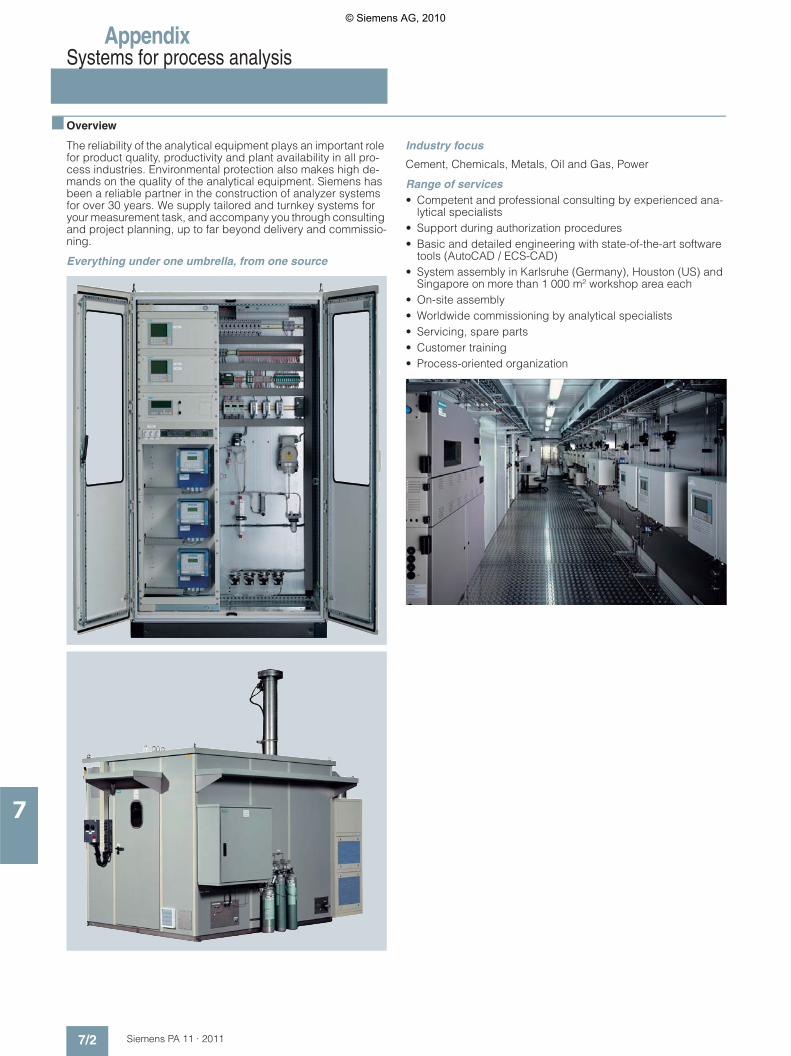
AppendixSystems for process analysis
7/2 Siemens PA 11 · 2011
7
■ Overview
The reliability of the analytical equipment plays an important role for product quality, productivity and plant availability in all pro-cess industries. Environmental protection also makes high de-mands on the quality of the analytical equipment. Siemens has been a reliable partner in the construction of analyzer systems for over 30 years. We supply tailored and turnkey systems for your measurement task, and accompany you through consulting and project planning, up to far beyond delivery and commissio-ning.
Everything under one umbrella, from one source
Industry focus
Cement, Chemicals, Metals, Oil and Gas, Power
Range of services• Competent and professional consulting by experienced ana-
lytical specialists• Support during authorization procedures• Basic and detailed engineering with state-of-the-art software
tools (AutoCAD / ECS-CAD)• System assembly in Karlsruhe (Germany), Houston (US) and
Singapore on more than 1 000 m² workshop area each• On-site assembly• Worldwide commissioning by analytical specialists• Servicing, spare parts• Customer training• Process-oriented organization
© Siemens AG, 2010
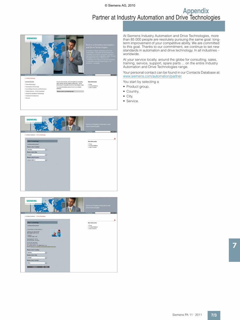
AppendixPartner at Industry Automation and Drive Technologies
7/3Siemens PA 11 · 2011
7
At Siemens Industry Automation and Drive Technologies, more than 85 000 people are resolutely pursuing the same goal: long-term improvement of your competitive ability. We are committed to this goal. Thanks to our commitment, we continue to set new standards in automation and drive technology. In all industries – worldwide.
At your service locally, around the globe for consulting, sales, training, service, support, spare parts ... on the entire Industry Automation and Drive Technologies range.
Your personal contact can be found in our Contacts Database at:www.siemens.com/automation/partner
You start by selecting a• Product group, • Country, • City, • Service.
© Siemens AG, 2010

AppendixOnline ServicesInformation and Ordering in the Internet and on DVD
7/4 Siemens PA 11 · 2011
7
■ Siemens Industry Automation and Drive Technologies in the WWW
A detailed knowledge of the range of products and services available is essential when planning and configuring automation systems. It goes without saying that this information must always be fully up-to-date.
Siemens Industry Automation and Drive Technologies has therefore built up a comprehensive range of information in the World Wide Web, which offers quick and easy access to all data required.
Under the address
www.siemens.com/industry
you will find everything you need to know about products, sys-tems and services.
■ Product Selection Using the Offline Mall of Industry
Detailed information together with convenient interactive functions: The Offline Mall CA 01 covers more than 80 000 products and thus provides a full summary of the Siemens Industry Automation and Drive Technologies product base.
Here you will find everything that you need to solve tasks in the fields of automation, switchgear, installation and drives. All information is linked into a user interface which is easy to work with and intuitive.
After selecting the product of your choice you can order at the press of a button, by fax or by online link.
Information on the Offline Mall CA 01 can be found in the Internet under
www.siemens.com/automation/ca01
or on DVD.
■ Easy Shopping with the Industry Mall
The Industry Mall is the virtual department store of Siemens AG in the Internet. Here you have access to a huge range of pro-ducts presented in electronic catalogs in an informative and at-tractive way.
Data transfer via EDIFACT allows the whole procedure from selection through ordering to tracking of the order to be carried out online via the Internet.
Numerous functions are available to support you.
For example, powerful search functions make it easy to find the required products, which can be immediately checked for avai-lability. Customer-specific discounts and preparation of quotes can be carried out online as well as order tracking and tracing.
Please visit the Industry Mall on the Internet under:
www.siemens.com/industrymall
© Siemens AG, 2010
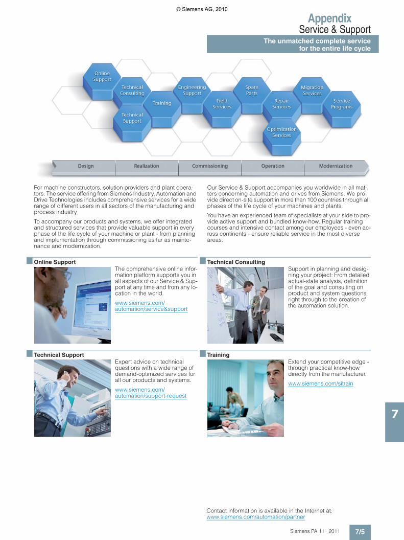
AppendixService & Support
The unmatched complete servicefor the entire life cycle
7/5Siemens PA 11 · 2011
7
For machine constructors, solution providers and plant opera-tors: The service offering from Siemens Industry, Automation and Drive Technologies includes comprehensive services for a wide range of different users in all sectors of the manufacturing and process industry
To accompany our products and systems, we offer integrated and structured services that provide valuable support in every phase of the life cycle of your machine or plant - from planning and implementation through commissioning as far as mainte-nance and modernization.
Our Service & Support accompanies you worldwide in all mat-ters concerning automation and drives from Siemens. We pro-vide direct on-site support in more than 100 countries through all phases of the life cycle of your machines and plants.
You have an experienced team of specialists at your side to pro-vide active support and bundled know-how. Regular training courses and intensive contact among our employees - even ac-ross continents - ensure reliable service in the most diverse areas.
■ Online SupportThe comprehensive online infor-mation platform supports you in all aspects of our Service & Sup-port at any time and from any lo-cation in the world.
www.siemens.com/automation/service&support
■ Technical SupportExpert advice on technical questions with a wide range of demand-optimized services for all our products and systems.
www.siemens.com/automation/support-request
■ Technical ConsultingSupport in planning and desig-ning your project: From detailed actual-state analysis, definition of the goal and consulting on product and system questions right through to the creation of the automation solution.
■ TrainingExtend your competitive edge - through practical know-how directly from the manufacturer.
www.siemens.com/sitrain
Contact information is available in the Internet at: www.siemens.com/automation/partner
© Siemens AG, 2010

AppendixService & SupportThe unmatched complete service for the entire life cycle
7/6 Siemens PA 11 · 2011
7
■ Engineering SupportSupport during project enginee-ring and development with ser-vices fine-tuned to your requirements, from configurati-on through to implementation of an automation project.
■ Field ServiceOur Field Service offers you ser-vices for commissioning and maintenance - to ensure that your machines and plants are always available.
■ Spare partsIn every sector worldwide, plants and systems are required to operate with constantly incre-asing reliability. We will provide you with the support you need to prevent a standstill from occur-ring in the first place: with a worldwide network and optimum logistics chains.
■ RepairsDowntimes cause problems in the plant as well as unnecessary costs. We can help you to redu-ce both to a minimum - with our worldwide repair facilities.
■ OptimizationDuring the service life of machi-nes and plants, there is often a great potential for increasing productivity or reducing costs. To help you achieve this potenti-al, we are offering a complete range of optimization services.
■ ModernizationYou can also rely on our support when it comes to modernization - with comprehensive services from the planning phase all the way to commissioning.
■ Service programsOur service programs are selec-ted service packages for an au-tomation and drives system or product group. The individual services are coordinated with each over to ensure smooth co-verage of the entire life cycle and support optimum use of your products and systems.
The services of a Service Pro-gram can be flexibly adapted at any time and used separately.
Examples of service programs:7 Service contracts7 Plant IT Security Services7 Life Cycle Services for Drive Engineering7 SIMATIC PCS 7 Life Cycle Services7 SINUMERIK Manufacturing Excellence7 SIMATIC Remote Support Servicess
Advantages at a glance:7 Reduced downtimes for increased productivity7 Optimized maintenance costs due to a tailored scope of ser-
vices7 Costs that can be calculated and therefore planned7 Service reliability due to guaranteed response times and
spare part delivery times7 Customer service personnel will be supported and relieved of
additional tasks7 Comprehensive service from a single source, fewer interfaces
and greater expertise
Contact information is available in the Internet at: www.siemens.com/automation/partner
© Siemens AG, 2010

AppendixService & Support
7/7Siemens PA 11 · 2011
7
■ Knowledge Base on DVD
For locations without online con-nections to the Internet there are excerpts of the free part of the information sources available on DVD (Service & Support Know-ledge Base). This DVD contains all the latest product information at the time of production (FAQs, Downloads, Tips and Tricks, Up-dates) as well as general infor-mation on Service & Support.
The DVD also includes a full-text search and our Knowledge Ma-nager for targeted searches for solutions. The DVD will be upda-ted every 4 months.
Just the same as our online offer in the Internet, the Service & Support Knowledge Base on DVD comes complete in 5 langua-ges (German, English, French, Italian, Spanish).
You can order the Service & Support Knowledge Base DVD from your Siemens contact.
Order no. 6ZB5310-0EP30-0BA2
■ Automation Value Card
Small card - great support
The Automation Value Card is an integral component of the com-prehensive service concept with which Siemens Automation and Drives will accompany you in each phase of your automation project.
It doesn't matter whether you want just specific services from our Technical Support or want to purchase something on our Online portal, you can always pay with your Automation Value Card. No invoicing, transparent and safe. With your personal card number and associated PIN you can view the state of your account and all transactions at any time.
Services on card. This is how it's done.
Card number and PIN are on the back of the Automation Value Card. When delivered, the PIN is covered by a scratch field, gu-aranteeing that the full credit is on the card.
By entering the card number and PIN you have full access to the Service & Support services being offered. The charge for the services procured is debited from the credits on your Automa-tion Value Card.
All the services offered are marked in currency-neutral credits, so you can use the Automation Value Card worldwide.
Order your Automation and Value Card easily and comfortably like a product with your sales contact.
Detailed information on the services offered is available on our Internet site at:
www.siemens.com/automation/service&support
Service & Support à la Card: Examples
Automation Value Card order numbers
Credits Order no.
200 6ES7 997-0BA00-0XA0
500 6ES7 997-0BB00-0XA0
1 000 6ES7 997-0BC00-0XA0
10 000 6ES7 997-0BG00-0XA0
Technical Support
”Priority“ Priority processing for urgent cases
”24 h“ Availability round the clock
”Extended“ Technical consulting for complex questions
”Mature Products“
Consulting service for products that are not available any more
Support Tools in the Support Shop
Tools that can be used directly for configuration, ana-lysis and testing
© Siemens AG, 2010

AppendixSubject index
7/8 Siemens PA 11 · 2011
7
8
8022 evaluation unit ...............................................................6/7
C
Coalescence filter ..................................................................5/3
Compressor gas cooler ........................................................5/15
Condensation removal .........................................................5/12
Condensation tank ...............................................................5/12
Condensation trap ................................................................5/11
Control assemblies for shut-off ball valves ..........................5/26
F
Filter ........................................................................................5/2
Fitting ....................................................................................5/49
Flowmeter .............................................................................5/35
Front mounting filter ...............................................................5/2
G
Gas .......................................................................................5/44
Gas cooler ............................................................................5/15
Gas measuring and warning systems ....................................6/2
Gas sampling probe ..............................................................2/2
H
Heated sample gas lines .......................................................4/2
Hose pump ...........................................................................5/14
L
Low-pressure overflow valve.................................................5/23
M
Moisture sensor ......................................................................5/7
Multiway ball valve ...............................................................5/25
N
Needle valve ........................................................................5/22
NO2-NO converter ................................................................5/47
Non-return valves .................................................................5/23
P
Preliminary condensation tank .............................................5/13
Pressure reducers ................................................................5/39
Pump ......................................................................................3/2
Pure gases ...........................................................................5/44
R
Reference gas monitoring OXYMAT .....................................5/46
Room air filter .........................................................................5/2
S
Sample gas pumps ................................................................3/2
Sensor ....................................................................................6/2
Shut-off and multiway ball valves made of PVDF .................5/26
Shut-off ball valve .................................................................5/24
Solenoid valve ......................................................................5/27
U
Universal filter .........................................................................5/5
V
Valve .....................................................................................5/22
W
Wiring modules ......................................................................5/7
© Siemens AG, 2010

AppendixOrder No. index
7/9Siemens PA 11 · 2011
7
3RS1...
3RS1 042-1GW70 .....................................................4/2, 4/3, 4/4
7MB1 940-...
7MB1 940-1FA00 .................................................................5/22
7MB1 940-1HA01 .................................................................5/28
7MB1 940-1NA00 .................................................................5/45
7MB1 940-6AA01 ..........................................................2/8, 5/49
7MB1 940-6AA06 .................................................................5/48
7MB1 940-6AA08 .................................................................5/48
7MB1 940-6AB01 ..........................................................2/8, 5/49
7MB1 940-6AC00 .................................................................5/49
7MB1 940-6AF00 ........................................................5/45, 5/49
7MB1 943-1...
7MB1 943-1EA01 ...................................................................2/2
7MB1 943-1EA02 ...................................................................2/2
7MB1 943-1MA01-1CB1 ......................................................5/39
7MB1 943-1MA01-1EB1 .......................................................5/39
7MB1 943-1MA01-3CB1 ......................................................5/39
7MB1 943-1MB01-1CB1 ......................................................5/39
7MB1 943-1MB01-3CB1 ......................................................5/39
7MB1 943-1PA01-2AB6 .......................................................5/38
7MB1 943-1PA01-2AC6 .......................................................5/38
7MB1 943-1PB01-2AB3 .......................................................5/38
7MB1 943-1PB01-2AB5 .......................................................5/38
7MB1 943-1QA01-1AB* .......................................................5/41
7MB1 943-1QA01-1AC* .......................................................5/41
7MB1 943-1QA01-3AB* .......................................................5/41
7MB1 943-1QA01-3AC* .......................................................5/41
7MB1 943-1QB01-1AB* .......................................................5/41
7MB1 943-1QB01-1AC* .......................................................5/41
7MB1 943-1QB01-3AB* .......................................................5/41
7MB1 943-1QB01-3AC* .......................................................5/41
7MB1 943-1RA01-4AB7 .......................................................5/42
7MB1 943-1RA01-4AC7 .......................................................5/42
7MB1 943-1RB01-4AB7 .......................................................5/42
7MB1 943-1RB01-4AC7 .......................................................5/42
7MB1 943-1SA01-1AB1 .......................................................5/40
7MB1 943-1SA02-1AB1 .......................................................5/40
7MB1 943-1TA01-1CB1 .......................................................5/39
7MB1 943-2...
7MB1 943-2AA01 ...................................................................4/3
7MB1 943-2AA02 ...................................................................4/3
7MB1 943-2AA41 .................................................................5/13
7MB1 943-2AA44 .................................................................5/13
7MB1 943-2AA45 .................................................................5/13
7MB1 943-2AA46 .................................................................5/13
7MB1 943-2AA47 .................................................................5/13
7MB1 943-2AA48 .................................................................5/13
7MB1 943-2AA50 .................................................................5/13
7MB1 943-2AA65 .................................................................5/12
7MB1 943-2AA66 .................................................................5/12
7MB1 943-2AA74 ...................................................................4/4
7MB1 943-2AA75 ...................................................................4/4
7MB1 943-2AA76 ...................................................................4/4
7MB1 943-2AA77 ...................................................................4/4
7MB1 943-2AA80 ...................................................................4/5
7MB1 943-2AA81 ...................................................................4/5
7MB1 943-2AB10 ...................................................................4/2
7MB1 943-2AB12 ...................................................................4/2
7MB1 943-2AB13 ...................................................................4/2
7MB1 943-2AB14 ...................................................................4/2
7MB1 943-2AB16 ...................................................................4/2
7MB1 943-2AB20 ...................................................................4/2
7MB1 943-2AB22 ...................................................................4/2
7MB1 943-2AB24 ...................................................................4/2
7MB1 943-2AB26 ...................................................................4/2
7MB1 943-2AC00 ...................................................................5/5
7MB1 943-2AC01 ...................................................................5/5
7MB1 943-2AC06 ...................................................................5/7
7MB1 943-2AC10 ...................................................................5/5
7MB1 943-2AC11 ...................................................................5/5
7MB1 943-2AC12 ...................................................................5/3
7MB1 943-2AC13 ...................................................................5/3
7MB1 943-2AC31 .................................................................5/11
7MB1 943-2AC32 .................................................................5/11
7MB1 943-2AC33 .................................................................5/11
7MB1 943-2AC34 .................................................................5/11
7MB1 943-2AC35 .................................................................5/11
7MB1 943-2AC36 .................................................................5/11
7MB1 943-2AC37 .................................................................5/11
7MB1 943-2AC38 .................................................................5/11
7MB1 943-2AC40 ...................................................................5/7
7MB1 943-2AC41 ...................................................................5/7
7MB1 943-2AC42 ...................................................................5/7
7MB1 943-2AC43 ...................................................................5/7
7MB1 943-2AC44 ...................................................................5/9
7MB1 943-2AC45 ...................................................................5/9
7MB1 943-2AC46 ...................................................................5/9
7MB1 943-2AC47 ...................................................................5/9
7MB1 943-2AC48 ...................................................................5/9
7MB1 943-2AC50 ...................................................................5/9
7MB1 943-2AC51 ...................................................................5/7
7MB1 943-2BA00 ...................................................................4/3
7MB1 943-2BA13 .................................................................5/22
7MB1 943-2BA20 .................................................................5/24
7MB1 943-2BA22 .................................................................5/25
© Siemens AG, 2010

AppendixOrder No. index
7/10 Siemens PA 11 · 2011
7
7MB1 943-2BA25 .................................................................5/26
7MB1 943-2BA30 .................................................................5/26
7MB1 943-2BA35 .................................................................5/26
7MB1 943-2BA40 .................................................................5/26
7MB1 943-2BA50 .................................................................5/27
7MB1 943-2BA55 .................................................................5/27
7MB1 943-2BA60 .................................................................5/28
7MB1 943-2BA65 .................................................................5/30
7MB1 943-2BA67 .................................................................5/30
7MB1 943-2BA70 ........................................................5/31, 5/45
7MB1 943-2BA75 ........................................................5/31, 5/45
7MB1 943-2BA86 .................................................................5/29
7MB1 943-2BA87 .................................................................5/29
7MB1 943-2BA88 .................................................................5/32
7MB1 943-2BA90 .................................................................5/32
7MB1 943-2BA91 ........................................................5/29, 5/32
7MB1 943-2BA92 ........................................................5/29, 5/32
7MB1 943-2BB20 .............................5/27, 5/28, 5/30, 5/31, 5/33
7MB1 943-2BB22 .............................5/27, 5/28, 5/30, 5/31, 5/33
7MB1 943-2BB30 .................................................................5/35
7MB1 943-2BB31 .................................................................5/35
7MB1 943-2BB35 .................................................................5/35
7MB1 943-2BB36 .................................................................5/35
7MB1 943-2BB41 .................................................................5/37
7MB1 943-2BB42 .................................................................5/37
7MB1 943-2BB43 .................................................................5/37
7MB1 943-2BB44 .................................................................5/37
7MB1 943-2BB45 .................................................................5/36
7MB1 943-2BB46 .................................................................5/37
7MB1 943-2BB47 .................................................................5/37
7MB1 943-2BB48 .................................................................5/36
7MB1 943-2BB50 .................................................................5/34
7MB1 943-2BB51 .................................................................5/34
7MB1 943-2BB52 .................................................................5/34
7MB1 943-2BB53 .................................................................5/34
7MB1 943-2BB55 .................................................................5/34
7MB1 943-2BB58 .................................................................5/34
7MB1 943-2BB60 .................................................................5/34
7MB1 943-2BB61 .................................................................5/34
7MB1 943-2BB62 .................................................................5/34
7MB1 943-2BB63 .................................................................5/34
7MB1 943-2BB64 .................................................................5/34
7MB1 943-2BB65 .................................................................5/34
7MB1 943-2CA30 ...................................................................5/2
7MB1 943-2CA32 ...................................................................5/2
7MB1 943-2DA02 .................................................................5/48
7MB1 943-2DA06 .................................................................5/48
7MB1 943-2DA10 .................................................2/8, 5/24, 5/49
7MB1 943-2DA12 .................................................................5/48
7MB1 943-2DA13 .................................................................5/49
7MB1 943-2DA14 .................................................................5/49
7MB1 943-2DA15 .................................................................5/48
7MB1 943-2DA16 .................................................................5/48
7MB1 943-2DA17 .................................................................5/48
7MB1 943-2DA18 .................................................................5/48
7MB1 943-2DA20 ..........................................................2/8, 5/49
7MB1 943-2DA21 .................................................................5/49
7MB1 943-2DA22 .................................................................5/49
7MB1 943-2DA24 .................................................................5/49
7MB1 943-2DA26 .................................................................5/49
7MB1 943-2DA27 .................................................................5/49
7MB1 943-2DA28 .................................................................5/49
7MB1 943-2DA30 .................................................................5/49
7MB1 943-2DA32 .................................................................5/49
7MB1 943-2DA33 .................................................................5/49
7MB1 943-2DA40 ........................................................5/45, 5/49
7MB1 943-2DA42 ........................................................5/45, 5/49
7MB1 943-2DA43 .................................................................5/49
7MB1 943-2DA45 .................................................................5/49
7MB1 943-2DB10 .................................................................5/49
7MB1 943-2DB40 .................................................................5/47
7MB1 943-2DB41 .................................................................5/47
7MB1 943-2DB42 .................................................................5/47
7MB1 943-2DB43 .................................................................5/47
7MB1 943-2DB44 .................................................................5/47
7MB1 943-2EA00 .................................................................5/26
7MB1 943-2EA02 .................................................................5/24
7MB1 943-2EA04 .................................................................5/26
7MB1 943-2EA06 .................................................................5/26
7MB1 943-2EA08 .................................................................5/25
7MB1 943-2EA10 .................................................................5/26
7MB1 943-2EA20 .................................................................5/25
7MB1 943-2EC00 .................................................................5/23
7MB1 943-2EC02 .................................................................5/23
7MB1 943-2EC04 .................................................................5/23
7MB1 943-2EC06 .................................................................5/23
7MB1 943-2FA00 ...................................................................2/3
7MB1 943-2FB01 ...................................................................2/4
7MB1 943-2FB02 ...................................................................2/4
7MB1 943-2FC01 ...................................................................2/5
7MB1 943-2FC02 ...................................................................2/5
7MB1 943-2FE00 ....................................................................2/8
7MB1 943-2FE01 ....................................................................2/8
7MB1 943-2FE02 ....................................................................2/8
7MB1 943-2FE03 ....................................................................2/8
7MB1 943-2FE04 ....................................................................2/8
© Siemens AG, 2010

AppendixOrder No. index
7/11Siemens PA 11 · 2011
7
7MB1 943-2FE06 ....................................................................2/8
7MB1 943-2FE07 ....................................................................2/8
7MB1 943-2FE08 ....................................................................2/8
7MB1 943-2FE12 ....................................................................2/8
7MB1 943-2FE13 ....................................................................2/8
7MB1 943-2FE14 ....................................................................2/8
7MB1 943-2FE20 ....................................................................2/8
7MB1 943-2FE21 ....................................................................2/8
7MB1 943-2FE22 ....................................................................2/8
7MB1 943-2FE23 ....................................................................2/8
7MB1 943-2FE41 ....................................................................2/8
7MB1 943-2FE42 ....................................................................2/8
7MB1 943-2FE43 ....................................................................2/8
7MB1 943-2FE44 ....................................................................2/8
7MB1 943-2FF01 ....................................................................2/6
7MB1 943-2FF02 ....................................................................2/6
7MB1 943-2FF03 ....................................................................2/6
7MB1 943-2FF04 ....................................................................2/6
7MB1 943-3...
7MB1 943-3AA00 ...................................................................3/2
7MB1 943-3AA02 ...................................................................3/2
7MB1 943-3AA03 ...................................................................3/2
7MB1 943-3AA04 ...................................................................3/2
7MB1 943-3AA20 .................................................................5/14
7MB1 943-3AA22 .................................................................5/14
7MB1 943-3AA26 .................................................................5/20
7MB1 943-3AA27 .................................................................5/20
7MB1 943-3AA28 .................................................................5/20
7MB1 943-3AC40 .................................................................5/20
7MB1 943-3AC41 .................................................................5/20
7MB1 943-3BB45 .................................................................5/20
7MB1 943-3BB46 .................................................................5/20
7MB1 943-3BB47 .................................................................5/20
7MB1 943-3BB48 .................................................................5/20
7MB1 943-3BB50 .................................................................5/20
7MB1 943-3BB51 .................................................................5/20
7MB1 943-3BB52 .................................................................5/20
7MB1 943-3BB53 .................................................................5/20
7MB1 943-3BB54 .................................................................5/20
7MB1 943-3BB55 .................................................................5/21
7MB1 943-3BB56 .................................................................5/21
7MB1 943-3BB57 .................................................................5/21
7MB1 943-3BB58 .................................................................5/21
7MB1 943-3BB60 .................................................................5/20
7MB1 943-3CA10 ...................................................................3/3
7MB1 943-3CA15 ............................................................3/3, 3/6
7MB1 943-3CA16 ..............................................3/3, 3/4, 3/6, 3/8
7MB1 943-3CA17 ..............................................3/3, 3/4, 3/6, 3/8
7MB1 943-3CA18 ............................................................3/4, 3/8
7MB1 943-3CA20 ...................................................................3/3
7MB1 943-3CA21 ...................................................................3/4
7MB1 943-3CA22 ...................................................................3/4
7MB1 943-3CA23 ...................................................................3/6
7MB1 943-3CA24 ...................................................................3/6
7MB1 943-3CA25 ...................................................................3/8
7MB1 943-3CA26 ...................................................................3/8
7MB1 943-3CB01 .................................................................3/10
7MB1 943-3CB11 .................................................................3/10
7MB1 943-3CB17 .................................................................3/10
7MB1 943-3CB18 .................................................................3/10
7MB1 943-5...
7MB1 943-5AA00 .................................................................5/43
7MB1 943-5AA01 .................................................................5/43
7MB1 943-5AA02 .................................................................5/43
7MB1 943-5AA03 .................................................................5/43
7MB1 943-5AA04 .................................................................5/43
7MB1 943-5AA05 .................................................................5/43
7MB1 943-5AA06 .................................................................5/43
7MB1 943-5AA07 .................................................................5/43
7MB1 943-5AA08 .................................................................5/43
7MB1 943-5AA10 .................................................................5/43
7MB1 943-5AA11 .................................................................5/43
7MB1 943-5AA12 .................................................................5/43
7MB1 943-5AA13 .................................................................5/43
7MB1 943-5AA14 .................................................................5/43
7MB1 943-5AA15 .................................................................5/43
7MB1 943-5AA16 .................................................................5/43
7MB1 943-5AA17 .................................................................5/43
7MB1 943-5AA18 .................................................................5/43
7MB1 943-5AA20 .................................................................5/43
7MB1 943-5AA21 .................................................................5/43
7MB1 943-5AA22 .................................................................5/43
7MB1 943-5AA23 .................................................................5/43
7MB1 943-5AA24 .................................................................5/43
7MB1 943-5AA25 .................................................................5/43
7MB1 943-5AA26 .................................................................5/43
7MB1 943-5AA27 .................................................................5/43
7MB1 943-5AA28 .................................................................5/43
7MB1 943-5AA30 .................................................................5/43
7MB1 943-5AA31 .................................................................5/43
7MB1 943-5AB00 .................................................................5/44
7MB1 943-5AB02 .................................................................5/44
7MB1 943-5AB04 .................................................................5/44
7MB1 943-5AB05 .................................................................5/44
7MB1 943-5AB06 .................................................................5/44
7MB1 943-5AB07 .................................................................5/44
© Siemens AG, 2010
AppendixOrder No. index
7/12 Siemens PA 11 · 2011
7
7MB1 943-5AB08 .................................................................5/44
7MB1 943-5AB10 .................................................................5/44
7MB1 943-5AB11 .................................................................5/44
7MB1 943-6...
7MB1 943-6AB01 .................................................................5/24
7MB1 943-6EA00 ...................................................................6/6
7MB1 943-6EA01 ...................................................................6/6
7MB1 943-6EA02 ...................................................................6/6
7MB1 943-6EA03 ...................................................................6/6
7MB1 943-6EA04 ...................................................................6/6
7MB1 943-6EA05 ...................................................................6/6
7MB1 943-6EA06 ...................................................................6/6
7MB1 943-6EA07 ...................................................................6/6
7MB1 943-6EA08 ...................................................................6/6
7MB1 943-6EA11 ...................................................................6/6
7MB1 943-6EA12 ...................................................................6/6
7MB1 943-6EA13 ...................................................................6/6
7MB1 943-6EA16-0A ..............................................................6/4
7MB1 943-6EA16-0B ..............................................................6/4
7MB1 943-6EA16-0C .............................................................6/4
7MB1 943-6EA16-0D .............................................................6/4
7MB1 943-6EA16-0E ..............................................................6/4
7MB1 943-6EA16-0F ..............................................................6/4
7MB1 943-6EA16-0G .............................................................6/4
7MB1 943-6EA16-0H .............................................................6/4
7MB1 943-6EA16-0J ..............................................................6/4
7MB1 943-6EA16-0K ..............................................................6/4
7MB1 943-6EA16-0L ..............................................................6/4
7MB1 943-6EA17 ...................................................................6/4
7MB1 943-6EA18-0A ..............................................................6/4
7MB1 943-6EA18-0B ..............................................................6/4
7MB1 943-6EA18-0C .............................................................6/4
7MB1 943-6EA18-0D .............................................................6/4
7MB1 943-6EA18-0E ..............................................................6/4
7MB1 943-6EA18-0F ..............................................................6/4
7MB1 943-6EA18-0G .............................................................6/4
7MB1 943-6EA18-0H .............................................................6/4
7MB1 943-6EA18-0J ..............................................................6/4
7MB1 943-6EA18-0K ..............................................................6/4
7MB1 943-6EA18-0L ..............................................................6/4
7MB1 943-6EA30 ...................................................................6/7
7MB1 943-6EA35 ...................................................................6/7
7MB1 943-6EA40 ...................................................................6/7
7MB1 943-6EA45 ...................................................................6/7
7MB1 943-6EA50 ...................................................................6/7
7MB1 943-6EA55 ...................................................................6/7
7MB1 943-6EA60 ...................................................................6/7
7MB1 943-6EA65 ...................................................................6/7
7MB1 943-6EA66 ...................................................................6/7
7MB1 943-6EA67 ...................................................................6/8
7MB1 943-6EA68 ...................................................................6/8
7MB1 943-6EA74 ...................................................................6/8
7MB1 943-6EA75 ...................................................................6/8
7MB1 943-6EA76 ...................................................................6/8
7MB1 943-6EA77 ...................................................................6/8
7MB1 943-6EB00 ...................................................................6/6
7MB1 943-6EB01 ...................................................................6/6
7MB1 943-6EB02 ...................................................................6/6
7MB1 943-6EB03 ...................................................................6/6
7MB1 943-6EB04 ...................................................................6/6
7MB1 943-6EB05 ...................................................................6/6
7MB1 943-6EB06 ...................................................................6/6
7MB1 943-6EB07 ...................................................................6/6
7MB1 943-6EB08 ...................................................................6/6
7MB1 943-6EB10 ...................................................................6/6
7MB1 943-6EB11 ...................................................................6/6
7MB1 943-6EB12 ...................................................................6/6
7MB1 943-6EC01 ...................................................................6/6
7MB1 943-6EC02 ...................................................................6/6
7MB1 943-6EC03 ...................................................................6/6
7MB1 943-6EC04 ...................................................................6/6
7MB1 943-6EC05 ...................................................................6/6
7MB1 943-6EC06 ...................................................................6/6
7MB1 943-6EC07 ...................................................................6/6
7MB1 943-6EC08 ...................................................................6/6
C
C79127-Z400-A1 ....................................................................5/2
© Siemens AG, 2010

AppendixOrder No. index
7/13Siemens PA 11 · 2011
7
© Siemens AG, 2010

AppendixConditions of sale and delivery, Export regulations
7/14 Siemens PA 11 · 2011
7
■ Terms and Conditions of Sale and Delivery
By using this catalog you can acquire hardware and software products described therein from Siemens AG subject to the fol-lowing terms. Please note! The scope, the quality and the condi-tions for supplies and services, including software products, by any Siemens entity having a registered office outside of Ger-many, shall be subject exclusively to the General Terms and Conditions of the respective Siemens entity. The following terms apply exclusively for orders placed with Siemens AG.
For customers with a seat or registered office in GermanyThe “General Terms of Payment” as well as the “General Condi-tions for the Supply of Products and Services of the Electrical and Electronics Industry” shall apply.For software products, the “General License Conditions for Soft-ware Products for Automation and Drives for Customers with a Seat or registered Office in Germany” shall apply.
For customers with a seat or registered office outside of GermanyThe “General Terms of Payment” as well as the “General Condi-tions for Supplies of Siemens, Automation and Drives for Cus-tomers with a Seat or registered Office outside of Germany” shall apply.For software products, the “General License Conditions for Soft-ware Products for Automation and Drives for Customers with a Seat or registered Office outside of Germany” shall apply.
GeneralThe dimensions are in mm. In Germany, according to the Ger-man law on units in measuring technology, data in inches only apply to devices for export. Illustrations are not binding.Insofar as there are no remarks on the corresponding pages, - especially with regard to data, dimensions and weights given - these are subject to change without prior notice.The prices are in € (Euro) ex works, exclusive packaging.The sales tax (value added tax) is not included in the prices. It shall be debited separately at the respective rate according to the applicable legal regulations.Prices are subject to change without prior notice. We will debit the prices valid at the time of delivery.Surcharges will be added to the prices of products that contain silver, copper, aluminum, lead and/or gold if the respective basic official prices for these metals are exceeded. These surcharges will be determined based on the official price and the metal fac-tor of the respective product.The surcharge will be calculated on the basis of the official price on the day prior to receipt of the order or prior to the release order.The metal factor determines the official price as of which the metal surcharges are charged and the calculation method used. The metal factor, provided it is relevant, is included with the price information of the respective products.
An exact explanation of the metal factor and the text of the Comprehensive Terms and Conditions of Sale and Delivery are available free of charge from your local Siemens business office under the following Order Nos.:• 6ZB5310-0KR30-0BA1
(for customers based in Germany)• 6ZB5310-0KS53-0BA1
(for customers based outside Germany)or download them from the Internetwww.siemens.com/industrymall (Germany: Industry Mall Online-Help System)
■ Export regulations
Our obligation to fulfill this agreement is subject to the proviso that the fulfillment is not prevented by any impediments arising out of national and international foreign trade and customs requirements or any embargos and/or other sanctions.If you transfer goods (hardware and/ or software and/ or tech-nology as well as corresponding documentation, regardless of the mode of provision) delivered by us or works and services (including all kinds of technical support) performed by us to a third party worldwide, you shall comply with all applicable national and international (re-) export control regulations. If required to conduct export control checks, you, upon request by us, shall promptly provide us with all information pertaining to particular end customer, destination and intended use of goods, works and services provided by us, as well as any export control restrictions existing.The products listed in this catalog / price list may be subject to European / German and/or US export regulations.Therefore, any export requiring a license is subject to approval by the competent authorities.According to current provisions, the following export regulations must be observed with respect to the products featured in this catalog / price list:
Even without a label or with an “AL: N” or “ECCN: N”, authoriza-tion may be required due to the final destination and purpose for which the goods are to be used. The deciding factors are the AL or ECCN export authorization indicated on order confirmations, delivery notes and invoices.Errors excepted and subject to change without prior notice.
AL Number of the German Export ListProducts marked other than “N” require an export license. In the case of software products, the export des-ignations of the relevant data medium must also be generally adhered to.Goods labeled with an “AL“ not equal to “N” are subject to a European or German export authori-zation when being exported out of the EU.
ECCN Export Control Classification NumberProducts marked other than “N” are subject to a reexport license to specific countries.In the case of software products, the exportdesignations of the relevant data medium must also be generally adhered to.Goods labeled with an “ECCN“ not equal to “N” are subject to a US re-export authorization.
© Siemens AG, 2010
CatalogsIndustry Automation, Drive Technologies and Low Voltage Distribution
Further information can be obtained from our branch offices listedin the appendix or at www.siemens.com/automation/partner
Interactive Catalog on DVD Catalogfor Industry Automation, Drive Technologies and Low Voltage Distribution
CA 01
Drive SystemsVariable-Speed Drives
SINAMICS G110, SINAMICS G120 Standard Inverters SINAMICS G110D, SINAMICS G120D Distributed Inverters
D 11.1
SINAMICS G130 Drive Converter Chassis Units SINAMICS G150 Drive Converter Cabinet Units
D 11
SINAMICS GM150, SINAMICS SM150 Medium-Voltage Converters
D 12
SINAMICS S120 Chassis Format Units and Cabinet Modules SINAMICS S150 Converter Cabinet Units
D 21.3
SINAMICS DCM Converter Units D 23.1
Three-phase Induction Motors• H-compact• H-compact PLUS
D 84.1
Asynchronous Motors Standardline D 86.1
Synchronous Motors with Permanent-Magnet Technology, HT-direct
D 86.2
DC Motors DA 12
SIMOREG DC MASTER 6RA70 Digital Chassis Converters
DA 21.1
SIMOREG K 6RA22 Analog Chassis Converters DA 21.2
PDF: SIMOREG DC MASTER 6RM70 Digital Converter Cabinet Units
DA 22
SIMOVERT PM Modular Converter Systems DA 45
SIEMOSYN Motors DA 48
MICROMASTER 420/430/440 Inverters DA 51.2
MICROMASTER 411/COMBIMASTER 411 DA 51.3
SIMOVERT MASTERDRIVES Vector Control DA 65.10
SIMOVERT MASTERDRIVES Motion Control DA 65.11
Synchronous and asynchronous servomotors for SIMOVERT MASTERDRIVES
DA 65.3
SIMODRIVE 611 universal and POSMO DA 65.4
SIMOTION, SINAMICS S120 and Motors for Production Machines
PM 21
SINAMICS S110 The Basic Positioning Drive
PM 22
Low-Voltage Three-Phase-Motors
IEC Squirrel-Cage Motors D 81.1
MOTOX Geared Motors D 87.1
Automation Systems for Machine Tools SIMODRIVE• Motors• Converter Systems SIMODRIVE 611/POSMO
NC 60
Automation Systems for Machine Tools SINAMICS• Motors• Drive System SINAMICS S120
NC 61
Drive and Control Components for Hoisting Equipment HE 1
Mechanical Driving Machines
Flender Standard Couplings MD 10.1
Electrical Installation TechnologyPDF: ALPHA Distribution Boards and Terminal Blocks ET A1
PDF: ALPHA 8HP Molded-Plastic Distribution System ET A3
PDF: BETA Low-Voltage Circuit Protection ET B1
PDF: DELTA Switches and Socket Outlets ET D1
PDF: GAMMA Building Management Systems ET G1
PDF: These catalogs are only available as pdf files.
Motion Control Catalog
SINUMERIK & SIMODRIVE Automation Systems for Machine Tools
NC 60
SINUMERIK & SINAMICS Equipment for Machine Tools
NC 61
SIMOTION, SINAMICS S120 and Motors for Production Machines
PM 21
SINAMICS S110 The Basic Positioning Drive
PM 22
Low-VoltageControls and Distribution – SIRIUS, SENTRON, SIVACON
LV 1
SICUBE System Cubicles and Cubicle Air-Conditioning LV 50
PDF: SIDAC Reactors and Filters LV 60
PDF: SIVACON 8PS Busbar Trunking Systems LV 70
Low-Voltage Controls and Distribution – SIRIUS, SENTRON, SIVACON
LV 90
Power Supply and System CablingPower supply SITOP KT 10.1
System cabling SIMATIC TOP connect KT 10.2
Process Instrumentation and AnalyticsField Instruments for Process Automation FI 01
SIREC Recorders and Accessories MP 20
SIPART, Controllers and Software MP 31
Products for Weighing Technology WT 10
PDF: Process Analytical Instruments PA 01
PDF: Process Analytics, Components for the System Integration
PA 11
Safety IntegratedSafety Technology for Factory Automation SI 10
SIMATIC HMI/PC-based AutomationHuman Machine Interface Systems/PC-based Automation
ST 80/ ST PC
SIMATIC Industrial Automation SystemsProducts for Totally Integrated Automation and Micro Automation
ST 70
SIMATIC PCS 7 Process Control System ST PCS 7
Add-ons for the SIMATIC PCS 7 Process Control System
ST PCS 7.1
PDF: Migration solutions with the SIMATIC PCS 7 Process Control System
ST PCS 7.2
SIMATIC NETIndustrial Communication IK PI
SIMATIC SensorsSensor Technology for Factory Automation FS 10
Industrial Identification Systems ID 10
System SolutionsApplications and Products for Industry are part of the interactive catalog CA 01
Download-Center
PDF versions of the catalogs are available on the Internet at:www.siemens.com/automation/infocenter
© Siemens AG, 2010

The information provided in this catalog contains descriptions or characteristics of performance which in case of actual use do not always apply as described or which may change as a result of further development of the products. An obligation to provide the respective characteristics shall only exist if expressly agreed in the terms of contract. Availability and technical specifications are subject to change without notice.All product designations may be trademarks or product names of Siemens AG or supplier companies whose use by third parties for their own purposes could violate the rights of the owners.www.siemens.com/processanalytics
Subject to change without prior noticeOnly PDF (E86060-K3511-A100-A8-7600)3P.8315.55.02KG 1010 112 EnPrinted in Germany © Siemens AG 2010
Siemens AGIndustry SectorSensors and Communications76181 KARLSRUHEGERMANY
PA11_2011_EN.indd 1 04.11.2010 08:58:51
© Siemens AG, 2010