Catalog October 2016 - BPX b SoMachine programming software is powerful and intuitive, making it...
29
Catalog October 2016 Modicon M241 logic controllers
-
Upload
vuongtuyen -
Category
Documents
-
view
213 -
download
0
Transcript of Catalog October 2016 - BPX b SoMachine programming software is powerful and intuitive, making it...

Catalog
October 2016
Modicon M241 logic controllers

Quick access to Product informationSelect your Catalogue, your Training
With just 3 clicks, you can reach the 7,000 pages of the Automation & Industrial Control catalogue, in both English and French.
– Digi-Cat is available on a USB key (for PC). To get your Digi-Cat, please contact your local center
– Download Digi-Cat from this address:
http://digi-cat.schneider-electric.com/download.html
Find your training
– Find the right training for your needs
– Locate the training center with the selector tool, using this address:
http://www.schneider-electric.com/b2b/en/services/training/technical-training.jsp
then click on

1
ModiconTM M241 logic controllers b Selection guide: ModiconTM M241 logic controllers ............................... page 2
b Presentation
- Applications, key features ...................................................................... page 4
- I/O cartridges, Application cartridges ..................................................... page 5
- Communication modules ....................................................................... page 5
- Options .................................................................................................. page 5
- Embedded communication .........................................................pages 6 and 7
- I/O extensions with Modicon TM3 expansion modules .......................... page 8
b Description
- Modicon M241 logic controllers ............................................................. page 9
b References
- Modicon M241 logic controllers ........................................................... page 10
- I/O cartridges, Application cartridges ................................................... page 10
- Separate parts, software, cordsets .......................................................page 11
Modicon TM4 communication modules b Switch Ethernet module
- Presentation, description ..................................................................... page 12
- References .......................................................................................... page 13
b Profibus DP slave module
- Presentation, description ..................................................................... page 12
- References ......................................................................................... page 13
Communication bus b Serial links (Modbus protocols, character mode)
- Presentation, description ..................................................................... page 14
- References ...............................................................................page 14 and 15
b CANopen Architecture
- Presentation, description ..................................................................... page 16
- References .......................................................................................... page 17
b Industrial Ethernet
- Presentation ........................................................................................ page 18
- Main equipment supported .................................................................. page 19
- Web Server .......................................................................................... page 19
- Ethernet services description............................................................... page 20
- Transparent Ready class and Functions .............................................. page 21
- Description of Ethernet embedded ports on controllers ....................... page 21
- Industrial Ethernet architecture ............................................................ page 22
- Connection cable references ............................................................... page 23
b Communication via Modem and routers
- Presentation, description ..................................................................... page 24
- References .......................................................................................... page 25
Compatibility b Compatibility of Modicon TM2 expansion modules
with Modicon M241 logic controllers ......................................................... page 26
Products reference index ................................................................. page 27
General contents

2 22 3
Selection guide Modicon M241 logic controllers
Applications Control of simple motionControl of control loops
Control of simple motionControl of control loops
Supply voltage 100-240 Va 24 Vc 100-240 Va 24 Vc
I/O b Logic I/O 24 logic I/O 40 logic I/O v No. and type of inputs 14 sink/source 24 V c inputs,
inc. 8 high-speed inputs14 sink/source 24 V c inputs, inc. 8 high-speed inputs
14 sink/source 24 V c inputs, inc. 8 high-speed inputs
24 sink/source 24 Vc inputs,inc. 8 high-speed inputs
24 sink/source 24 Vc inputs,inc. 8 high-speed inputs
24 sink/source 24 Vc inputs,inc. 8 high-speed inputs
v No. and type of outputs 10 outputs: with 4 source transistor high-speed outputs and 6 relay outputs
10 source transistor outputs, inc. 4 high-speed outputs
10 sink transistor outputs, inc. 4 high-speed outputs
16 outputs: with 4 source transistor high-speed outputs and 12 relay outputs
16 source transistor outputs, inc. 4 high-speed outputs
16 sink transistor outputs, inc. 4 high-speed outputs
Connection of logic inputs/outputs Removable screw terminal block Removable screw terminal block
I/O extension v 7 Modicon TM3 expansion modules v 14 Modicon TM3 expansion modules with transmitter and receiver bus expansion modules v Possible use of Modicon TM2 expansion modules with restrictions
v 7 Modicon TM3 expansion modules v 14 Modicon TM3 expansion modules with transmitter and receiver bus expansion modules v Possible use of Modicon TM2 expansion modules with restrictions
Embedded communication
Ethernet link 1 Ethernet port on TM241CE24p and TM241CEC24p controllers: v Protocols: Modbus TCP (Client/Server), Modbus TCP slave, EtherNet/IP adapter/originator (1) v Services: firmware updates, data exchange - NGVL and IEC VAR ACCESS, Web server,
SNMP-MIB2 network management, FTP (Client/Server), SNMP (Client/Server), SQL (Client), email library, DHCP Client, programming, downloading, monitoring
v Services: Modbus TCP Scanner Manager and EtherNet/IP Scanner Manager, email, on TM241CE24p controllers
1 Ethernet port on TM241CE40p controllers: v Protocols: Modbus TCP (Client/Server), Modbus TCP slave, EtherNet/IP adapter/originator v Services: firmware updates, data exchange - NGVL and IEC VAR ACCESS, Web server, SNMP-MIB2 network management, FTP (Client/Server), SNMP
(Client/Server), SQL (Client), email library, DHCP Client, programming, downloading, monitoring
v Services: Modbus TCP Scanner Manager and EtherNet/IP Scanner Manager, email, on TM241CE40p controllers
CANopen link On TM241CEC24p controllers: 1 port for CANopen fieldbus (1 screw terminal block) with CANopen (Master) and SAE J1939 (Request Manager) protocols
–
Serial link 2 serial link ports: v 1 SL1 port (RJ45), RS232/485 with +5 V power supply v 1 SL2 port (screw terminals) RS485
2 serial link ports: v 1 SL1 port (RJ45), RS232/485 with +5 V power supply v 1 SL2 port (screw terminals) RS485
Functions Process control PID PIDCounting 8 high-speed counter (HSC) inputs, 200 kHz frequency 8 high-speed counter (HSC) inputs, 200 kHz frequencyPosition control 4 position control outputs
v P/D, CW, and CCW pulse train output (PTO), 100 kHz frequency v pulse width modulation (PWM) v frequency generator (FG)
4 position control outputs v P/D, CW, and CCW pulse train output (PTO), 100 kHz frequency v pulse width modulation (PWM) v frequency generator (FG)
Options b Cartridges v 3 I/O expansion cartridges: - with 2 voltage/current analog inputs - with 2 inputs for temperature probes - with 2 voltage/current analog outputs
v 2 application cartridges: - for control of hoisting applications - for control of packaging applications
v 3 I/O expansion cartridges: - with 2 voltage/current analog inputs - with 2 inputs for temperature probes - with 2 voltage/current analog outputs
v 2 application cartridges: - for control of hoisting applications - for control of packaging applications
Number of cartridge slots 1 2
b Communication modules v 1 Ethernet port Modicon TM4 module with switch function and 4 embedded ports v 1 Modicon TM4 module for Profibus DP slave link
v 1 Ethernet port Modicon TM4 module with switch function and 4 embedded ports v 1 Modicon TM4 module for Profibus DP slave link
Mounting Mounting on 5 rail or panel Mounting on 5 rail or panel
Software programming With SoMachine software (please consult our website: www.schneider-electric.com) With SoMachine software (please consult our website: www.schneider-electric.com)
Controller type With serial links TM241C24R TM241C24T TM241C24U TM241C40R TM241C40T TM241C40UWith embedded Ethernet port and serial links
TM241CE24R TM241CE24T TM241CE24U TM241CE40R TM241CE40T TM241CE40U
With embedded Ethernet and CANopen ports, and serial links
TM241CEC24R TM241CEC24T TM241CEC24U – – –
Page 10 10(1) Excludes TM241CEC24p

4
Presentation Modicon M241 logic controllersGeneral presentation
Compatibility of offersModicon M241 logic controllers> Modicon TM3 expansion modules> Modicon TM2 expansion modules> Modicon TM4 communication modules> SoMachine software
PresentationApplications
Modicon M241 logic controllers are designed for high-performance compact machines incorporating speed and position control functions.They have an embedded Ethernet port offering FTP (Client/Server), Web server, and SQL (Client) services, meaning they can be easily integrated into control system architectures for remote machine monitoring and maintenance via apps for smartphones, tablets, and PCs.
b This wide variety of embedded functions helps minimize the cost of the machine: - Functions embedded in the controller: Modbus serial link, dedicated USB
programming port, Ethernet I/O Scanner, CANopen, and SAE J1939 fieldbuses for distributed architectures, advanced position control functions (high-speed counters and pulse train outputs for servo motor control)
- Functions embedded in the Modicon TM3 extensions: functional safety modules, motor-starter control module, and remote expansion system
- Functions embedded in the Modicon TM4 communication modules b The processing power and memory capacity of M241 controllers are ideal for
targeting high-performance applications. b SoMachine programming software is powerful and intuitive, making it quick to
create applications. Existing applications can easily be retrieved from Modicon M221, M238, and M258 ranges, thus helping to protect the investment already made.
Main functionsM241 logic controllers come in two formats (W x H x D):
v Controllers with 24 I/O: 150 x 90 x 95 mm (5.90 x 3.54 x 3.74 in.) v Controllers with 40 I/O: 190 x 90 x 95 mm (7.48 x 3.54 x 3.74 in.)
v Inputs and outputs embedded in M241 controllers are connected on removable screw terminal blocks, supplied with the controllers.
v A Run/Stop switch is available on each M241 controller.
v Each M241 controller has a slot for an industrial SD (Secure Digital) memory card.
A slot integrated in each M241 controller can take up to two cartridges of the following types:
v Analog input or output expansion cartridges v Application cartridges for hoisting or packaging
Each M241 logic controller has a QR code for direct access to its technical documentation.
Embedded communicationM241 logic controllers have up to 5 embedded communication ports:
v Ethernet with embedded Web server function v CANopen: CANopen (Master) and SAE J1939 (Request Manager) v 2 serial links v USB mini-B programming port
Embedded functions v PID control v 8 high-speed counter (HSC) inputs, 200 kHz frequency v 4 position control channels for:
- P/D, CW, and CCW pulse train output (PTO), 100 kHz frequency - pulse width modulation (PWM) - frequency generator (FG)
Processing power v Execution speed: 22 ns/Boolean instruction with 128 KB Boolean instructions in
the program v DualCore processor v Program size: 10 MB for application and symbols v RAM: 64 MB v Flash memory: 128 MB
ProgrammingM241 logic controllers are programmed using SoMachine software.
M241 logic controller with 24 I/O
M241 logic controller with 40 I/O
SoMachine software
Example of a QR code:QR code for accessing the TM241CEC24R logic controller technical documentation
5
Presentation (continued) Modicon M241 logic controllersOptions for Modicon M241 controllers
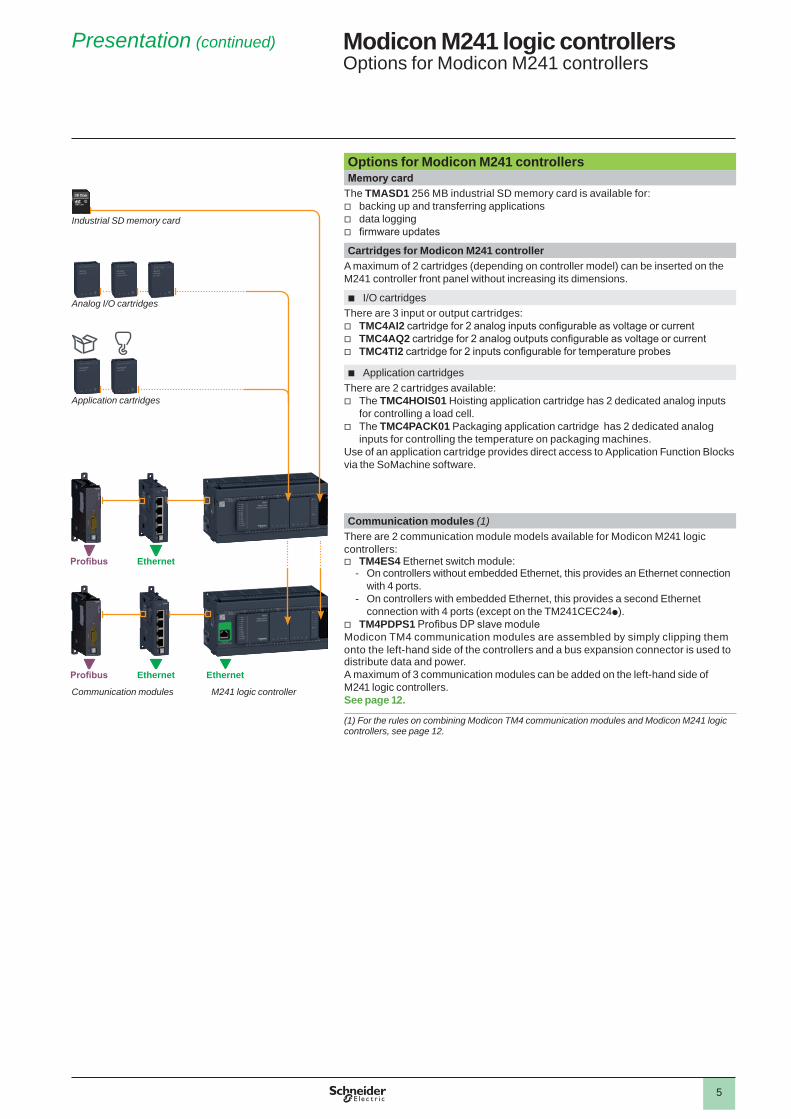
Options for Modicon M241 controllersMemory card
The TMASD1 256 MB industrial SD memory card is available for: v backing up and transferring applications v data logging v firmware updates
Cartridges for Modicon M241 controllerA maximum of 2 cartridges (depending on controller model) can be inserted on the M241 controller front panel without increasing its dimensions.
b I/O cartridgesThere are 3 input or output cartridges:
v TMC4AI2 cartridge for 2 analog inputs configurable as voltage or current v TMC4AQ2 cartridge for 2 analog outputs configurable as voltage or current v TMC4TI2 cartridge for 2 inputs configurable for temperature probes
b Application cartridgesThere are 2 cartridges available:
v The TMC4HOIS01 Hoisting application cartridge has 2 dedicated analog inputs for controlling a load cell.
v The TMC4PACK01 Packaging application cartridge has 2 dedicated analog inputs for controlling the temperature on packaging machines.
Use of an application cartridge provides direct access to Application Function Blocks via the SoMachine software.
Communication modules (1)There are 2 communication module models available for Modicon M241 logic controllers:
v TM4ES4 Ethernet switch module: - On controllers without embedded Ethernet, this provides an Ethernet connection
with 4 ports. - On controllers with embedded Ethernet, this provides a second Ethernet
connection with 4 ports (except on the TM241CEC24p). v TM4PDPS1 Profibus DP slave module
Modicon TM4 communication modules are assembled by simply clipping them onto the left-hand side of the controllers and a bus expansion connector is used to distribute data and power.A maximum of 3 communication modules can be added on the left-hand side of M241 logic controllers.See page 12.
(1) For the rules on combining Modicon TM4 communication modules and Modicon M241 logic controllers, see page 12.
Industrial SD memory card
Application cartridges
Analog I/O cartridges
M241 logic controllerCommunication modules
Profibus Ethernet
Profibus Ethernet Ethernet

6
Presentation (continued) Modicon M241 logic controllersEmbedded communication
Embedded communicationM241 logic controllers have up to 5 embedded communication ports:
v 2 serial links - SL1 (RJ 45) and SL2 (screw terminals) - and 1 programming port (USB mini-B) on each controller
v 1 Ethernet port (RJ 45) or 1 Ethernet port (RJ 45) and 1 CANopen port depending on the controller model
Communication over Ethernet
TM241CEppp controllers have an embedded Ethernet RJ45 port (10/100 Mbps, MDI/MDIX) with Modbus TCP (Client/Server), EtherNet/IP (adapter/originator (1)), I/O Scanner (1), UDP, TCP, SQL (Client), SNMP (Client/Server), and SoMachine protocols.
v M241 controllers each have an embedded Web server and embedded FTP (Client/Server). As well as the default address based on the MAC address, a controller IP address can be assigned via a DHCP server or via a BOOTP server.
v The Ethernet port also offers the same upload/download, update, and debugging functions as the programming port (USB mini-B) when the controller power is on.
v A firewall allows the authorized IP addresses for accessing the controller to be filtered and each communication protocol to be locked.
v The embedded Ethernet port is optimized for connecting field devices (variable speed drives, distributed I/O, etc.), via an RJ45 connection, with the EtherNet/IP Scanner (1), Modbus TCP I/O Scanner (1), EtherNet Modbus TCP (Client/Server), EtherNet/IP (originator (1) and adapter), UDP, TCP, SNMP, and SoMachine services. - EtherNet/IP Scanner (1) allows the connection of up to 16 slave devices
controlled by the controller in 10 ms (1,024 input words + 1,024 output words). - Modbus TCP I/O Scanner (1) allows the connection of up to 64 slave devices
controlled by the controller in 64 ms. v A second Ethernet link is possible on TM241CEppp controllers (1) as an option
using the TM4ES4 module optimized for connection to the “Machine” or “Factory” network (with 4 RJ45 connectors).
v Note: The TM241CEC controller does not support EtherNet/IP originator or I/O Scanner functions, or the second Ethernet link.
For Ethernet connection cables and accessories, see page 18.
Communication over CANopen
TM241CEC24p controllers have an embedded CANopen port for CANopen master communication.The link can be configured between 20 Kbps and 1 Mbps and supports up to 63 slaves.
v Architectures based on CANopen can be used to distribute I/O modules as close to the sensors and actuators as possible, thus reducing wiring costs and times, and to communicate with different devices such as variable speed drives and servo drives, etc.
v The CANopen configurator is integrated in the SoMachine software and can also be used to import standard description files in EDS format.
For CANopen connection cables and accessories, see page 14.
Communication over SAE J1939
The SAE J1939 protocol is available on the CANopen port on TM241CEC24p logic controllers.The SAE J1939 protocol is primarily used in commercial vehicles to communicate with the various electronic control units embedded in a vehicle, such as the engine, transmission, braking system, retarder, and dashboard.
(1) Except on TM241CEC24p controller. These controllers do not support EtherNet/IP (originator) or I/O Scanner functions, or the second Ethernet link.
132
M24
1_62
129_
AP
DLT
1600
1
1 Embedded Ethernet on TM241CEppp controllers2 TM4PDSP1 communication module (Profibus bus)3 TM4ES4 communication module (Ethernet)
Ethernet
Industrial Ethernet I/O Scanner
Magelis HMI Rotary encoders
8 HSC channels
Lexium 32 Lexium 32
CANopen
Profibus bus
1 TM241C24pp/TM241C40pp2 TM4PDSP1 communication module (Profibus bus)3 TM4ES4 communication module (Ethernet)4 TM241CEppp controllers (with embedded Ethernet)
1
4
23
Ethe
rnet
Ethernet
Ethernet
Magelis HMI Rotary encoders
8 HSC channels
2 PTO channels
Lexium 23+, BCH motors
Profibus bus
M24
1_62
129_
AP
DLT
1600
2
SAE J1939
Electronic control units
or

7
Presentation (continued) Modicon M241 logic controllersEmbedded communicationCommunication via modem and router
Embedded communicationSerial links
Each M241 controller has 2 embedded serial links. v The SL1 serial link can be configured as RS232 or RS485. In addition, a
5 V/200 mA power supply is available on the RJ45 connector that allows the use of a Magelis XBTN or XBTRT HMI, the Bluetooth® communication adapter TCSWAAC13FB, or other devices.
v The SL2 serial link is configured as RS485.Embedded in both links are the two main commercially-available protocols:
- Modbus ASCII/RTU Master or Slave - ASCII character string
For serial link connection cables and accessories, see page 15.
Programming port with power off charging function
Every M241 controller has an embedded programming port, equipped with a USB mini-B connector, dedicated to communication with a PC equipped with SoMachine for:
v programming v debugging v maintenance
In addition, it offers the ability to upload an application program or update the firmware without the controller being powered by another source.
Communication via modem and router
The communication via modem and router offer is dedicated to the following applications:
b Synchronization between remote machines; direct data exchange between controllers
b Remote maintenance; access to the controller via SoMachine programming software
b Remote control and monitoring of machines; receipt of information and sending of commands on GSM phone
This offer comprises 2 Schneider Electric modems (PSTN modem, GSM modem) and a VPN router made by eWon.For modems, router, and connection cables, see page 24.
M241 logic controller
GSM modem

8
Presentation (continued) Modicon M241 logic controllersI/O extensions with Modicon TM3 expansion modules
I/O extensions with Modicon TM3 modulesModicon TM3 expansion modules
The capacity of M241 logic controllers can be enhanced with the Modicon TM3 expansion module offer:
v Digital I/O modules that can be used to create configurations with up to 488 digital I/O. These modules are available with the same connections as the controllers.
v Analog I/O modules that can be used to create configurations with up to 114 analog I/O and are designed to receive, amongst other things, position, temperature, and speed sensor signals. They are also capable of controlling variable speed drives or any other device equipped with a current or voltage input.
v Expert modules for controlling TeSys motor starters, connected using RJ45 cables to simplify wiring of the control section.
v Functional safety modules that simplify wiring and can be configured in SoMachine.In addition, the TM3 expansion system offers flexibility due to the option to remotely locate some of the TM3 modules in the enclosure or another cabinet, up to 5 meters (16.404 ft.) away, using a bus expansion system.The Modicon TM3 expansion system is common to the whole range of Modicon M221, M241, and M251 logic controllers, meaning that the controller model can be upgraded without changing the extensions.
21
5 54
Local I/O< 7 modules max. >Embedded I/O
2 33 664
Remote I/O< 7 modules max. >
7
24 Vc
1 M241 logic controller2 Modicon TM3 digital I/O modules3 Modicon TM3 analog I/O modules (1)4 Modicon TM3 Expert module for controlling TeSys motor starters5 Modicon TM3 functional safety modules6 Modicon TM3 bus expansion modules (transmitter and receiver)7 TM3 bus expansion cable
(1) Compatibility of expansion module offers: The majority of Modicon TM2 expansion modules can be used with M241 logic controllers. Nonetheless, adding a Modicon TM2 expansion module to a configuration can increase the expansion module execution times by as much as a few milliseconds. The compatibility of Modicon TM2 expansion modules with M241 logic controllers is described in detail on page 26.

9
Description,characteristics
Modicon M241 logic controllersModicon M241 logic controllers
DescriptionM241 controllers
1 Removable screw terminal block with 3 terminals for connecting the 24 Vc or 100-240 Va 50/60 Hz power supply (depending on the model)
2 On TM241CEC24p controllers: connector for link to theCANopen and SAE J1939 machine bus (screw terminals)
3 On TM241CEppp controllers: RJ45 connector for Ethernet network with speed and activity LED
4 TM4 bus connector: communication bus for the link with TM4ppp communication modules
5 QR code for accessing the controller technical documentation6 Serial link port SL1 (RS232 or RS485): RJ45 connector7 Serial link port SL2 (RS485): screw terminals8 24 Vc logic input connection: removable screw terminal blocks (1)9 LED display block showing:
- the status of the controller and its components (battery, industrial SD memory card)
- the status of the embedded communication ports (CAN, serial links, Ethernet) - the status of the embedded I/O
10 TM3 bus connector for link to a Modicon TM3 expansion moduleBehind the removable cover: 11,12, 13, 14, 1511 Run/Stop switch12 Industrial SD memory card slot13 Backup battery slot14 Mini-B USB connector for a programming terminal15 Slot(s) for I/O cartridge(s) or application cartridge(s):
- 1 slot on TM241Cp24 - 2 slots on TM241Cp40
16 Clip for locking onto 5 symmetrical rail17 Connection of relay/transistor logic outputs: removable screw terminal blocks (1)
(1) Removable terminal blocks equipped with screw terminals. Terminal blocks supplied with controller.
Characteristics of M241 logic controllersConformity
b Certification v e, cULus Listing Mark, C-Tick, EAC, LR, ABS, DNV, and GL v ODVA and Achilles
b Standards v IEC/EN 61131-2 (Edition 2 2007), UL508 (UL61010-2-201),
ANSI/ISA 12.12.01-2007, CSA C22.2 No.213, No.142, E61131-2, and IACS E10
Environmental characteristics v Ambient operating temperature: -10...+55 °C (+14...+131 °F) v Storage temperature: -40...+70 °C (-40...+158 °F) v Relative humidity: 5...95% (non-condensing)
Operating altitude: v 0...2,000 m (0...6,562 ft) full specification for temperature and solar radiation v 2,000…4,000 m (6,562…13,123 ft):
- temperature derating: 1 °C/400 m (1.8 °F/1,312 ft.) - insulation losses: 150 Vc/1,000 m (150 Vc/3,280 ft.)
v Storage altitude: 0...3,000 m (0...9,842 ft) v Immunity to mechanical stress:
- For 1131 : 5...8.4 Hz (amplitude 3.5 mm/0.14 in.); 8.4...150 Hz (acceleration 1 g) - For merchant marine: 5…13.2 Hz (amplitude 1.0 mm/0.04 in.) ; 13.2...100 Hz
(acceleration 0.7 g)Power supply characteristics
There are 2 types of power supply depending on the M241 controller model: 24 V c or 100-240 Va 50/60 Hz.
v Voltage limit (including ripple): 19.2...28.8 Vc/85...264 Va
v Immunity to micro-breaks (class PS-2): 10 ms v Max. consumption: 45 W
M241 controllers with 24 I/O
M241 controllers with 40 I/O
1
6
7 8
9
15
1716
3
5
2
411121314
10
1
6
7 8
9
15
3
5
2
411121314
1716
10

10
References Modicon M241 logic controllersM241 logic controllers, options
ReferencesModicon M241 logic controllers (1)No. of logic I/O
Logic inputs Logic outputs Embedded communication ports (2) Reference Weightkglb
Ethernet(RJ45)
CANopen (screw terminals): CANopen/ SAE J1939
Serial links(RJ45 and screw terminals)
b 100-240 Va power supply24 I/O 14 sink/source
24 V c inputs,inc. 8 high- speed inputs
10 outputs: inc.4 source transistor high-speed outputs and 6 relay outputs
– – 1 + 1 TM241C24R 0.5301.168
1 – 1 + 1 TM241CE24R 0.5301.168
1 1 1 + 1 TM241CEC24R 0.5301.168
40 I/O 24 x 24 V c inputs, inc. 8 high-speed inputs
16 outputs: inc.4 source transistor high-speed outputs and 12 relay outputs
– – 1 + 1 TM241C40R 0.6201.367
1 – 1 + 1 TM241CE40R 0.6201.367
b 24 Vc power supply24 I/O 14 sink/source
24 V c inputs,inc. 8 high- speed inputs
10 source transistor outputs, inc. 4 high-speed outputs
– – 1 + 1 TM241C24T 0.5301.168
1 – 1 + 1 TM241CE24T 0.5301.168
1 1 1 + 1 TM241CEC24T 0.5301.168
14 sink/source 24 V c inputs,inc. 8 high- speed inputs
10 sink transistor outputs, inc. 4 high-speed outputs
– – 1 + 1 TM241C24U 0.5301.168
1 – 1 + 1 TM241CE24U 0.5301.168
1 1 1 + 1 TM241CEC24U 0.5301.168
40 I/O 24 sink/source 24 V c inputs,inc. 8 high- speed inputs
16 source transistor outputs, inc. 4 high-speed outputs
– – 1 + 1 TM241C40T 0.6201.367
1 – 1 + 1 TM241CE40T 0.6201.367
24 sink/source 24 V c inputs,inc. 8 high- speed inputs
16 sink transistor outputs, inc. 4 high-speed outputs
– – 1 + 1 TM241C40U 0.6201.367
1 – 1 + 1 TM241CE40U 0.6201.367
Options for Modicon M241 logic controllersDesignation Description Reference Weight
kglb
I/O cartridges
2 analog inputs (12-bit resolution) configurable as: - 0…10 V voltage - 0…20 mA/4…20 mA current
Screw terminal version
TMC4AI2 0.0250.055
2 analog outputs (12-bit resolution) configurable as: - 0…10 V voltage - 0…20 mA/4…20 mA current
Screw terminal version
TMC4AQ2 0.0250.055
2 inputs (14-bit resolution) configurable for RTD and TC temperature probesScrew terminal version
TMC4TI2 0.0250.055
Dedicated application cartridges
Hoisting application: 2 analog inputs for load cellScrew terminal version
TMC4HOIS01 0.0250.055
Packaging application: 2 analog inputsScrew terminal version
TMC4PACK01 0.0250.055
Industrial SD memory card Application backup and program transferCapacity: 256 MB
TMASD1 0.0040.009
(1) Modular M241 controllers are supplied with: - Removable terminal blocks (screw terminals) for connecting the I/O with thread of 3.81 mm (0.15 in.). - A removable terminal block for connecting the power supply with thread of 5.08 mm (0.2 in.). - A button cell backup battery (BR2032).
(2) Each M241 logic controller has an embedded USB mini-B programming port.
TM241C24R
TM241C40R
TM241CE24R
TM241CE40T
TM241CEC24U
TM241CE40U
TMC4AI2
TMC4TI2
TMC4AQ2
TMC4HOIS01 TMC4PACK01
TMASD1

11
References Modicon M241 logic controllersOptions, replacement parts, programming software, connection cables
ReferencesReplacement partsDesignation Description Unit reference Weight
kglb
Set of connectors for connecting the I/O
Removable screw terminal connectors: 8 different connectors for equipping an M241 logic controller (1 x SL2, 6 x I/O, 1 x CANopen)
TMAT4CSET 0.1270.280
Set of terminal blocks for connecting the power supply
8 removable screw terminal blocks TMAT2PSET 0.1270.280
Backup battery The battery supplied with each controller is not available as a spare part in the Schneider catalog. If a replacement part is needed, only use a Panasonic battery type BR2032.
Programming softwareDesignation Used for Reference
SoMachine software M241 logic controllers Please consult our website: www.schneider-electric.com
Expansion modulesDesignation Used for Reference
Modicon TM3 expansion modules
M241 logic controllers Please consult our website: www.schneider-electric.com
Communication modulesDesignation Used for Reference
Modicon TM4 communication modules
Ethernet port module, Profibus DP slave module See page 13
Connection cablesDesignation For use
From ToLength Reference Weight
kg lb
Programming cables PC USB port USB mini-B port on M221, M241, M251, and M258 controllers
3 m(0.98 ft.)
TCSXCNAMUM3P(1)
0.0650.143
1.8 m(5.90 ft.)
BMXXCAUSBH018 0.0650.143
(1) Unshielded, non-grounded cable. For use on temporary connections only. For permanent connections, use cable reference BMXXCAUSBH018.
TCSXCNAMUM3P

12
Presentation, description
Modicon M241 logic controllersModicon TM4 communication modulesFor Modicon M241 and Modicon M251 logic controllers
Compatibility of offersModicon TM4 communication modules> Modicon M241 logic controllers> Modicon M251 logic controllers
PresentationApplications
The Modicon TM4 offer is dedicated to Modicon M241 and M251 logic controllers and enhances their connectivity. There are 2 communication module models available:
v The TM4ES4 Ethernet switch module providing a 4-port Ethernet connection v The TM4PDPS1 Profibus DP slave module
b Ethernet switch module
The TM4ES4 module is a 4-port Ethernet interface (10/100 Mbps, MDI/MDIX) with the Ethernet Modbus TCP (Client/Server), Ethernet/IP (adapter), UDP, TCP, SNMP, and SoMachine protocols.
v The TM4ES4 module is ready for use as soon as it is connected to the communication bus of M241 and M251 controllers.
v This module is used to add Ethernet functionality to TM241C24p and TM241C40p controllers without embedded Ethernet port while offering the additional functionality of an Ethernet switch.
v When connected to TM241CE24ppp or TM241CE40ppp type logic controllers with embedded Ethernet port, it acts as a second Ethernet link for the “Machine” or “Factory” link.
v When connected to TM241CEppp type controllers with embedded Ethernet port, or to a TM251MESp controller, it can also act as a standalone 4-port switch: communication between the TM4ES4 module and Modicon M241 and M251 controllers does not occur automatically via the bus connector.
b Profibus DP slave moduleThe TM4PDPS1 communication module is used to configure a slave connection on the Profibus DP bus.
Combination rulesA maximum of 3 communication modules can be added on the left-hand side of M241 and M251 logic controllers in order to increase their connectivity to the Ethernet and Profibus networks.
v On TM241C24ppp, TM241C40ppp, TM241CE24ppp, and TM241CE40ppp controllers, it is possible to add a TM4ES4 module with Ethernet port function and 2 TM4ES4 modules with the standalone switch function while respecting the maximum number of 3 TM4 modules.
v On TM241CEC24p and TM251ppp modules, it is possible to add 3 TM4ES4 modules with the standalone switch function while respecting the maximum number of 3 TM4 modules.
v TM4 communication modules are assembled by simply clipping them onto the left-hand side of M241 and M251 logic controllers; a bus expansion connector is used to distribute data and power.
Description b TM4ES4 Ethernet switch module
1 Power on LED2 Bus connector (1 on each side)3 4 RJ45 connectors for Ethernet network with speed and activity LED4 Screw terminal connector for the functional ground (FG)5 Clip for locking onto symmetrical 5 rail
b TM4PDPS1 Profibus DP slave module
1 Power on LED2 Bus connector (1 on each side)3 9-way SUB-D connector for Profibus DP bus4 Screw terminal connector for the functional ground (FG)5 Clip for locking onto symmetrical 5 rail
Modicon TM4 communication modules
Modicon M241 logic controller
Modicon 251 logic controller
2 2
1
3
45
2 2
1
3
4
5

13
Presentation, references
Modicon M241 logic controllersModicon TM4 communication modulesFor Modicon M241 and Modicon M251 logic controllers
Ethernet servicesConfiguration Main Ethernet services for embedded
Ethernet port on M241 controllerMain Ethernet services for embedded Ethernet port on TM4ES4 module (without modifying the firmware)
TM241C controllers + TM4ES4 module None (no embedded Ethernet port) > EtherNet/IP Adapter > Modbus TCP Server > FTP Server > Web visualization > NGVL > Web system > Modbus TCP Slave
TM241C controllers + TM4ES4 module,not configured with SoMachine
None (no embedded Ethernet port) > FTP Server > Modbus TCP Server > Web visualization > NGVL > Web system
TM241CE controllers + TM4ES4 module,configured with SoMachine (version u 4.2)
> EtherNet/IP Originator I/O Scanner > Modbus TCP Client I/O Scanner > FTP Server > Web visualization > NGVL > Web system > DHCP Server
> EtherNet/IP Adapter > Modbus TCP Server > FTP Server > Web visualization > NGVL > Web system > Modbus TCP Slave
TM241CE controllers + TM4ES4 module,not configured with SoMachine (version u 4.2)
> EtherNet/IP Originator I/O Scanner > Modbus TCP Client I/O Scanner > FTP Server > Web visualization > NGVL > Web system > DHCP Server
Switch function only: no services
TM241CE controllers + TM4ES4 module,not configured with SoMachine (version < 4.2)
> EtherNet/IP Adapter > Modbus TCP Server > FTP Server > Web visualization > NGVL > Web system > Modbus TCP Slave
Switch function only: no services
TM241CEC controllers > EtherNet/IP Adapter > Modbus TCP Server > FTP Server > Web visualization > NGVL > Web system > Modbus TCP Slave
Switch function only: no services
ReferencesOptions for Modicon M241 and M251 logic controllersDesignation Description Reference Weight
kglb
Communication modules Ethernet switch module with embedded 4-port switch functionEquipped with 4 RJ45 connectors (10/100 Mbps, MDI/MDIX)
TM4ES4(1)
0.1100.243
Profibus DP slave moduleEquipped with 9-way SUB-D connector
TM4PDPS1 0.1100.243
(1) Can be used as Ethernet port or standalone switch according to controller model and configuration.
TM4ES4
TM4PDPS1

14
PresentationRS 232/RS 485 serial links offer a simple solution to the communication needs of machines. Modbus and ASCII standard communication protocols are used to connect numerous equipment items such as: HMIs, printers, energy meters, variable speed drives, motor starters, remote I/O (RIO), etc.
Description
21
Modicon M241 logic controllers have the following on their upper surface:1 A “Serial 1” serial link port with an RJ45 connector delivering a 5 V/200 mA power
supply which allows the use of a Magelis HMI, the Bluetooth® communication adapter or other devices.
2 A 2nd “Serial 2” serial link port (with connection on screw terminals).
Controller Type Embedded Ports“Serial 1” port, RJ45 connector “Serial 2” port, connection on screw
terminalsTM241pppp RS 232/RS 485 with 5V (200 mA)
power supply for HMI or Bluetooth communication adaptor (item 1)
RS 485 (item 2)
3
Modicon M251 logic controllers have on their front a serial link port with an RJ45 connector delivering a 5 V/200 mA power supply which allows the use of a Magelis HMI, the Bluetooth® communication adapter or other devices.3 A serial link port (RJ 45 connector (RS 232 or RS 485).
Modbus serial link wiring system Non-isolated bus Isolated bus (recommended for bus > 10 m (32.808 ft)
HMISCU
1 1
5 4
1
4
3
5
4 2
44 4
2
4
ON
Imax: 63A iEM
31
C/- DI N.C. C DO N.C.
0V D1/+D0/-
5
5 V c
6
6SL1SL2
SL1SL2
- Total length of cables between M241/M251 and ATV12: y 30 m (98.425 ft)- Length of cable 4: y 10 m (32.808 ft)g Line polarization active. b Line termination
- Total length of cables between isolation boxes 1: y 1000 m (3280.840 ft)- Length of drop cables 4 or 5: y 10 m (32.808 ft)g Line polarization active. b Line termination(1) Box powered by the logic controller.
g b b g b (1) b (1)
Master M241 / M251 Master M241 / M251 TeSys UAltivar 12 Altivar 312 Slave M221C
Phaseo power supply
Power meter
XBTN
OTB
3rd-party Modbus
slave
References Tap-off and adaptor components for RS 485 serial linkDesignation Description Item Length Unit reference Weight
kg lb
T-junction and isolation box Screw terminals for trunk cable2 x RJ45 for tap-off
v Isolation of the RS 485 link (1) v Line termination (RC 120 Ω, 1nF) v Line pre-polarization (2 R 620 Ω) v 24 V c power supply (screw terminals) or 5 V c power supply (via RJ45)
v Mounting on 35 mm (1.378 in.) 5
1 – TWDXCAISO 0.1000.220
T-junction box 1 x RJ45 for trunk cable2 x RJ45 for tap-off
v Line termination (RC 120 Ω, 1nF) v Line pre-polarization (2 R 620 Ω) v Mounting on 35 mm (1.378 in.) 5
2 – TWDXCAT3RJ 0.0800.176
(1) Line isolation recommended for line distances > 10 m (32.808 ft).
Modicon M241 logic controllersSerial linksModbus protocols, character mode
Presentation, description, schemes, references
TWDXCAISO TWDXCAT3RJ

15
References (continued)Designation Description Item Length Reference Weight
kglb
Tap-off and adaptor components for RS 485 serial linkModbus splitter box Screw terminals for trunk cable10 x RJ45 for tap-off
v Mounting on 35 mm (1.378 in.) 5 , on plate or panel
– – LU9GC3 0.5001.102
T-junctions2 x RJ45 for trunk cable
1 integrated cable with RJ45 connector for tap-off dedicated to Altivar variable speed drive
– 0.3 m0.984 ft
VW3A8306TF03 –
1 m3.281 ft
VW3A8306TF10 –
Passive T-junction box v 1-channel line extension and tap-off on screw terminals v Line termination
– – TSXSCA50 0.5201.146
RS 232C/RS 485 line converter
v Max. data rate 19.2 Kbps, No modem signals v 24 V c/20 mA power supply v Mounting on 35 mm (1.378 in.)
– – XGSZ24 0.1000.220
Cables and cordsets for RS 232 serial link RS 485 double shielded twisted pair trunk cables
Modbus serial link, supplied without connector 3 100 m328.084 ft
TSXCSA100 5.68011.023
200 m656.168 ft
TSXCSA200 10.92024.074
500 m1640.420 ft
TSXCSA500 30.00066.139
Modbus RS 485 cordsets
2 x RJ45 connectors 4 0.3 m0.984 ft
VW3A8306R03 0.0300.066
1 m3.281 ft
VW3A8306R10 0.0500.110
3 m9.843 ft
VW3A8306R30 0.1500.331
1 x RJ 45 connector and 1 end with flying leads
5 1 m3.281 ft
TWDXCAFJ010 0.0600.132
3 m9.843 ft
VW3A8306D30 0.1500.331
Cordsets: used from M241 (SL1), M251 controllers to Magelis HMI
2 x RJ45 connectorsCompatible with:
v Com Port 1 on XBTN200/N400/R400/RT500 (1) v Com Port 1 on XBTRT511 and HMISTO/STU/SCU v Com Port 2 on XBTGT2pp0...7pp0 and HMIGTO
6 2.5 m8.202 ft
XBTZ9980 0.2300.507
6 10 m32.81 ft
XBTZ9982 –
1 x RJ45 connector and 1 x 25-way SUB-D connectorCompatible with:
v Com Port 1 on XBTN410/N410 and XBTR410/R411
– 2.5 m8.202 ft
XBTZ938 0.2100.463
1 x RJ45 connector and 1 x 9-way SUB-D connectorCompatible with:
v Com Port 1 on XBTGT2pp0...7pp0
– 2.5 m8.202 ft
XBTZ9008 –
Cordsets: used from M241 (SL2) controllers to Magelis HMI
1 x RJ45 connector and stripped wiresCompatible with:
v Com Port 1 on XBTRT511 and HMISTO/STU/SCU v Com Port 2 on XBTGT2pp0...7pp0 and HMIGTO
– 3 m9.843 ft
VW3A8306D30 0.1500.331
Line end adapterSold in packs of 2
For RJ45 connector R = 120 Ω, C = 1 nf
– – VW3A8306RC 0.2000.441
Cordsets for RS 232 serial linkCordset for DTE terminal (printer) (2)
Serial link for Data Terminal Equipment (DTE) 1 x RJ45 connector and 1 x 9-way female SUB-D connector
3 m9.843 ft
TCSMCN3M4F3C2 0.1500.331
Cordset for DCE terminal (modem, converter)
Serial link for point to point device (DCE)1 x RJ45 connector and 1 x 9-way male SUB-D connector
3 m9.843 ft
TCSMCN3M4M3S2 0.1500.331
(1) If the terminal is equipped with a 25-way SUB-D connector, you will also need to order the TSXCTC07 25-way female / 9-way male SUB-D adaptor.
(2) Can only be connected to the controller SL or SL1 ports in order to supply the Magelis terminal with power.
Modicon M241 logic controllersSerial linksModbus protocols, character mode
References (continued)
LU9GC3
TSXSCA50
XGSZ24

16
PresentationSchneider Electric has selected CANopen for its machines and installations because of its wealth of functions and its resulting benefits in the automation world.This decision was based on the general acceptance of CANopen, and the fact that CANopen products are increasingly used in control system architectures.CANopen is an open network supported by more than 400 companies worldwide, and promoted by CAN in Automation (CiA). CANopen conforms to standards EN 50325-4 and ISO 15745-2. Schneider Electric is heavily involved in working groups, which are important for machine and installation architectures, systems and products.
v The bus uses a double shielded twisted pair on which, with Modicon M241 and Modicon M251 logic controllers, a maximum of 63 devices are connected by daisy-chaining or by tap junctions.
v Each end of the bus must be fitted with a line terminator. On M241 controllers, this line terminator is already integrated on the master side and can be disconnected using a switch located next to the CAN connector.
CANopen port on M241 and M251 controllersType M241: screw terminals
M251: 9-way SUB-DStandards DS 301 V4.02, DR 303-1Class M10Data rate
Max. length (m / ft.)
20/ 65.62
40/131.23
100/328.08
250/820.21
500/1640.42
1000/3280.84
2500/8202.1
5000/16404.2
Data rate (Kbps)
1000 800 500 250 125 50 20 10
Number of slaves
63 slaves max. with limit of: 252 RPDOs and 252 TPDOs
DescriptionCANopen port on M241 and M251 controllers
The underside of Modicon TM241CECppp logic controllers has:1 a connector for linking to the CANopen bus (screw terminals).2 a CANopen line termination switch.
The front of the Modicon TM251MESC logic controller has: 3 a connector for linking to the CANopen bus (9-way SUB-D).
Modicon M241 logic controllersCANopen architecture
Presentation
1
3
TM241CECppp controllers
TM251MESC controller
2
CANopen connection architecture
2
4 4 6 7 4 4 4
5 5
1 3 1
2
Ethernet
CA
Nop
en
CA
Nop
en
TM251MESC
Altivar 312 Altivar 71 Lexium 32Lexium 32 Modicon OTB Lexium 32
TM241CECppp
Altivar 32
Modicon TM7 (IP 67)

17
Modicon M241 logic controllersCANopen architecture
Description, references
ReferencesCANopen standard taps and connectorsDesignation Description Item Lgth.
mm / ftUnit reference Weight
kg / lbIP20 CANopen tap junction Line termination : 4 SUB-D ports. Screw terminals
for connecting the trunk cables 1 – TSXCANTDM4 0.196 / 0.432
IP 20 CANopen connectors 9-way female SUB-DLine end adapter switch
Right-angle 2 – TSXCANKCDF90T 0.046 / 0.101Straight (for connection to the Altivar IMC integrated controller card)
2 – TSXCANKCDF180T 0.049 / 0.108
Right-angle with 9-way SUB-D for connecting a PC or diagnostic tool
2 – TSXCANKCDF90TP 0.051 / 0.112
IP 20 CANopen tap junction for Altivar and Lexium 32
2 RJ45 ports 3 – VW3CANTAP2 0.250 / 0.551
Daisy chain taps Equipped with: v 2 sets of spring terminals for daisy chain connection of the CANopen bus
v 1 preassembled cordset with RJ45 connector for connecting the drive
– 0.6/ 1.97 TCSCTN026M16M –
Equipped with: v 2 RJ45 connectors for daisy chain connection of the CANopen bus
v 1 preassembled cordset with RJ45 connector for connecting the drive
– 0.3 / 0.98 TCSCTN023F13M03 –
CANopen line terminators For RJ45 connector Sold in lots of 2
– – TCSCAR013M120 –
For screw terminal connector Sold in lots of 2
– – TCSCAR01NM120 –
IP 20 standard cables and preassembled cordsets Designation Description Item Length Unit reference Weight
kg/ lbCANopen cables(2 x AWG 22 2 x AWG 24)
For standard environment (1), e marking: Low smoke. Zero halogen. Non flame propagating (IEC 60332-1)
5 50 / 164.042 TSXCANCA50 4.930 / 10.869100 / 328.08 TSXCANCA100 8.800 / 19.401 300 / 984.25 TSXCANCA300 24.560 / 54.146
For standard environment (1), UL certification, e marking: Flame-retardant (IEC 60332-2)
5 50 / 164.04 TSXCANCB50 3.580 / 7.893100 / 328.08 TSXCANCB100 7.840 / 17.284300 / 984.25 TSXCANCB300 21.870 / 48.215
For harsh environment (1) or mobile installation, e marking: Low smoke. Zero halogen. Non flame propagating (IEC 60332-1). Oil-resistant
5 50 / 164.04 TSXCANCD50 3.510 / 7.738100 / 328.08 TSXCANCD100 7.770 / 17.130300 / 984.25 TSXCANCD300 21.700 / 47.840
CANopen preassembled cordsets
Cordsets with one 9-way female SUB-D connector at each end
For standard environment (1), e marking: Low smoke. Zero halogen. Non flame propagating (IEC 60332-1)
6 0.3 / 0.98 TSXCANCADD03 0.091 / 0.2011 / 3.28 TSXCANCADD1 0.143 / 0.3153 / 9.84 TSXCANCADD3 0.295 / 0.6505 / 16.40 TSXCANCADD5 0.440 / 0.970
For standard environment (1), UL certification, e marking: Flame-retardant (IEC 60332-2)
6 0.3 / 0.98 TSXCANCBDD03 0.086 / 0.1901 / 3.28 TSXCANCBDD1 0.131 / 0.2893 / 9.84 TSXCANCBDD3 0.268 / 0.5915 / 16.40 TSXCANCBDD5 0.400 / 0.882
Cordsets with one 9-way female SUB-D connector and one RJ45 connector
4 0.5 /1.64 TCSCCN4F3M05T 0.100 / 0.2201 / 3.28 TCSCCN4F3M1T 0.100 / 0.2203 / 9.843 VW3M3805R010 (2) 0.100 / 0.2201 / 3.281 VW3M3805R030 (2) 0.300 / 0.6613 / 9.84 TCSCCN4F3M3T 0.160 / 0.353
Cordsets with two 9-way SUB-D connectors, one male and one female
– 0.5 / 1.64 TLACDCBA005 0.100 / 0.2201.5 / 4.92 TLACDCBA015 0.120 / 0.2653 / 9.84 TLACDCBA030 0.190 / 0.4195 / 16.40 TLACDCBA050 0.350 / 0.772
Preassembled cordsets with one RJ 45 connector at each end
7 0.3 / 0.984 VW3CANCARR03 0.100 / 0.2201 / 3.281 VW3CANCARR1 0.100 / 0.220
Adapter for Altivar 71 speed drive
One RJ45 connector at each end – – VW3CANA71 0.100 / 0.220
Taps and IP 67 accessoriesPlease consult the Modicon TM7 offer: interface blocks (IP 67) for distributed I/O on the CANopen bus Please consult on our website
www.schneider-electric.com(1) Standard environment: no particular environmental constraints, operating temperature between + 5°C and + 60°C (+ 41°F and + 140°F), and in
fixed installations.Harsh environment: resistance to hydrocarbons, industrial oils, detergents, solder splashes, relative humidity up to 100%, saline atmosphere, significant temperature variations, operating temperature between - 10°C and + 70°C (+ 14°F and +158°F), or in mobile installations.(2) Cordset equipped with a line terminator.
VW3CANTAP2
TSXCANTDM4
TSXCAN KCD F90T
TSXCAN KCD F180T
TSXCANKCD F90TP
TCSCAR013M120
VW3CANA71
18
Presentation Modicon M241 logic controllersIndustrial Ethernet network for Modicon M241 logic controllers and Modicon TM4ES4 Ethernet switch module
GeneralIndustrial Ethernet is the term used to refer to industrial communication protocols using Ethernet standard physical layers such as:
v EtherNet/IP v Modbus TCP v TCP and UDP
The following equipment can be connected to an Industrial Ethernet network: v industrial products (industrial communication protocols) such as controllers,
variable speed drives, robots, etc. v products using TCP/UDP-based proprietary protocols
In addition, it is possible to use different Ethernet Industrial protocols on the same network simultaneously.
EtherNet/IP protocol
EtherNet/IP is an industrial communication protocol based on CIP (Common Industrial Protocol), owned and managed by the ODVA, an independent standards organization (www.odva.org).EtherNet/IP is the result of implementing CIP on standard Ethernet. EtherNet/IP operates on the same device and the same infrastructure as Modbus TCP, and both protocols can be activated simultaneously on the network at any time.EtherNet/IP is a robust protocol for use with sophisticated devices, such as cameras and robots.Advanced services and outstanding performanceEtherNet/IP is object-oriented. In each EtherNet/IP device, the data is arranged as objects and each device can be associated with several types of object depending on its intended use. Integration of devices is made easy thanks to predefined and standard objects.The EtherNet/IP protocol uses an Originator/Adapter architecture to exchange data.
Modbus TCP/IP protocol
Modbus has been the industry communication standard since 1979. During the internet revolution, Modbus was combined with Ethernet to form Modbus TCP, a completely open Ethernet protocol.Modbus TCP, simple and openThe Modbus application layer is simple and universally familiar with its 9 million installed connections.
v Thousands of manufacturers have already implemented this protocol. Many have already developed a Modbus TCP connection and numerous products are currently available.
v The simplicity of Modbus TCP enables any fieldbus device, such as an I/O module, to communicate over Ethernet without the need for a powerful microprocessor or a lot of internal memory.Modbus TCP, a standard
v The application protocol is identical on Modbus serial link and Modbus TCP; messages can be routed from one network to the other without converting the protocol.
v Since Modbus operates on the TCP higher layer, users benefit from IP routing, thus enabling devices located anywhere in the world to communicate without worrying about the distance between them. Modbus and Modbus TCP are recognized as a fieldbus by the international standard IEC/EN 61158. They also comply with the “national Chinese standard” managed by ITEI.The Modbus TCP protocol uses a Client/Server architecture to exchange data.

19
Modicon M221, M241, and M251 logic controllersThe embedded Ethernet communication ports in Modicon M221, M241, and M251 logic controllers and in the Modicon TM4ES4 communication module optimize the capability for integration into factory network architectures.Modicon M221, M241, and M251 logic controllers can be easily integrated into typical architectures:
v machine-to-device (variable speed drives, remote I/O modules, operator dialog terminals) with the I/O Scanner function
v machine-to-machine with the NGVL function v machine-to-supervisory system with the Modbus Client/Server and EtherNet/IP
adapter functionsEthernet also brings transparency to the factory, in particular - thanks to the firewall functions - making it possible to perform the following functions securely from any point on the network:
v program, monitor a controller, or download an application v access device parameters (variable speed drives, for example)
A simple web browser can be used to access machines anytime anywhere, using a tablet or smartphone, for example, by means of the Web servers embedded in Modicon M241 and M251 controllers.Security can be enhanced through the use of VPN modems; refer to our partner program on our website www.schneider-electric.com > Products and Services > Automation and Control > Collaborative Automation Partner Program.
Main devices supportedDevice Protocols supported Integration tools in SoMachine
(1)TCP/UDP
Modbus TCP
EtherNet/IP
Altivar 32 – FDR, DTM, TVDAAltivar 320 – FDR, DTM, TVDAAltivar 340 – FDR, DTM, TVDAAltivar 71 – FDR, DTM, TVDALexium 32 M – FDR, DTM, TVDALexium ILA – FDR, librairies, TVDALexium ILE – FDR, librairies, TVDALexium ILS – FDR, librairies, TVDAOsiSense XG – TVDAOsiSense XUW – – TVDAModicon OTB1EODM9LP – – LibrariesPreventa XPSMCM – (2) TVDA for EtherNet/IPHarmony XB4R, XB5R – – DTM, librairiesModicon M221, M241, M251
User parameters (for EtherNet/IP only), librairies
Device supplied with EDS file (1)
– – User parameters
Generic device User parameters (for EtherNet/IP only), librairies
Web serversPreconfigured Web server
Using a simple web browser available on PC, smartphone, or tablet, this server authorizes the following “ready-to-use” functions:
v With no prior programming - Display of I/O states - Diagnostics of controller, expansion modules, and communication modules - Communication port diagnostics - I/O Scanner function diagnostics - Maintenance and configuration functions (EtherNet/IP, firewall, etc.)
v After configuration - Visualization of data values - Visualization of how these data values evolve over time (oscilloscope function)
Web visualization serverSoMachine programming software is used to create customized pages for visualizing and monitoring devices. These pages can also be accessed on any mobile device such as a tablet or smartphone with any operating system (iOS, Android, Windows).(1) SoMachine configuration software: please refer to catalog DIA3ED2140110EN.pdf or our website www.schneider-electric.com
- FDR: Fast Device Replacement - DTM: Device Type Manager - TVDA: Tested, Validated, Documented Architectures
(2) Integration as a generic device
Presentation Modicon M241 logic controllersIndustrial Ethernet network for Modicon M241 logic controllers and Modicon TM4ES4 Ethernet switch module
Web visualization server
Preconfigured Web server

20
Presentation Modicon M241 logic controllersIndustrial Ethernet network for Modicon M241 logic controllers and Modicon TM4ES4 Ethernet switch module
Description of Ethernet servicesNetwork Global Variable List (NGVL)The NGVL protocol allows a controller to share data with other controllers on a local Ethernet network (LAN) or subscribe to data published by other controllers that support the NGVL protocol thus allowing, for example, synchronization between control platforms.I/O scanning (Industrial Ethernet Manager)The Industrial Ethernet Manager service is used to manage the exchange of remote I/O states over Ethernet after a simple configuration operation, with no need for special programming.I/O scanning is performed transparently by means of read/write requests in accordance with the Modbus TCP or EtherNet/IP protocol; this is called Scanner Manager on Modbus TCP or Scanner Manager on EtherNet/IP.Modbus TCP SlaveThis function can be used to create a dedicated I/O table in the controller that can be accessed via the Modbus TCP protocol and by a controller with the Modbus TCP I/O Scanner function.Fast Device Replacement (FDR)This service uses standard address management technologies (BOOTP, DHCP) and the TFTP (Trivial File Transfer Protocol) file management service in order to simplify maintenance of Ethernet products.The FDR service is used to replace a device with a new device; the device is detected, reconfigured, and automatically rebooted by the system.Access to files via FTP (File Transfer Protocol)This service provides access to the controller files from, for example, a PC (FTP client) and is used to exchange files such as application programs, data, etc.This service can be accessed even if the controller has no application program in its memory.Dynamic Host Configuration Protocol (DHCP)This protocol is used to automatically assign an address to a controller (DHCP/BOOTP client). This address can be:
v fixed and determined either in the SoMachine software or included in a post-configuration file
v assigned by a controller with the DHCP server or BOOTP server function (such as the TM251MESE logic controller)SNMP (Simple Network Management Protocol)From a network management station, SNMP is used to monitor and control the Ethernet architecture components, allowing detected errors to be diagnosed quickly.The SNMP protocol is used to access configuration and management objects that are contained in the device MIBs (management information bases).Modicon M241 and M251 controllers support the “MIB 2 Standard” SNMP network management interface. This interface accesses a first level of network management; it enables the manager to identify the devices making up the architecture and retrieve general information about configuration and operation of the Ethernet Modbus TCP interfaces.IP address filter (Whitelisting)IP addresses that are authorized to access the controller can be loaded in the controller from either an SD card or an FTP client.Locking communication protocolsNot only SoMachine, NetManage (1), and SNMP communication protocols but also Modbus, WEB, and FTP servers can be locked individually in the SoMachine software.EtherNet/IP adapterThis function can be used to create a dedicated I/O table in the controller that can be accessed via the EtherNet/IP protocol and by a controller with the Ethernet/IP originator function. EtherNet/IP adapter is used in the same way for EtherNet/IP as a Modbus TCP slave.EtherNet/IP originatorControllers with this function trigger exchanges with devices featuring the Ethernet/IP adapter function. EtherNet/IP originator is used in the same way for EtherNet/IP as a Modbus TCP master.(1) The NetManage function can automatically detect which controllers are present on the network. It also offers the option of straightforward connection to any controller present on the network in order to identify it physically by means of a visual or audible message and modify its parameters or manage the resident application.
Ethernet TCP
Device input words/output words
WriteRead Modicon TM251MESE controller with Industrial Ethernet Manager service
Devices with Modbus TCP messaging in server mode or EtherNet/IP adapter messaging
I/O scanning (Industrial Ethernet Manager)

21
Presentation, characteristics, description
Modicon M241 logic controllersIndustrial Ethernet network for Modicon M241 logic controllers and Modicon TM4ES4 Ethernet switch module
Transparent Ready class and functionsLogic controllers TM4ES4 Ethernet
switch moduleTM221MEppp, TM221CEppp
TM241CEppp TM251MESC TM251MESE
Transparent Ready class A10 B20Internet protocol version IPV4
Ethernet servicesProgramming, downloading, monitoringFirmware update –Modbus TCP/IP (Client/Server)Modbus TCP SlaveEtherNet/IP adapterEtherNet/IP originator – (1) –Data exchange – NVGL and IEC VAR ACCESS –WEB server –SNMP.MIB2 (Client/Server) network management –Scanner Manager on Modbus TCP – (1) – Ethernet port 2Scanner Manager on EtherNet/IP – (1) – Ethernet port 2FTP (Client/Server) –DHCP Client Ethernet port 1DHCP Server – (1) – Ethernet port 2 –FDR – (1) – –SMS (2)SQL Client (3) – –E-mail, based on TCP/UDP library – –Security functions
IP address filter (Whitelisting) –Locking communication protocolsLocking IP address routing –(1) Except on TM241CEC24p controller.(2) With dedicated function block in SoMachine Basic software.(3) For more information, refer to the “SoMachine Configuration Software” catalog on our website www.schneider-electric.com.
Modicon M241 and M251 controller network characteristicsTopology Daisy chain and star using switchesBandwidth 10/100 MbpsEtherNet/IP scanner performance Up to 16 slave devices controlled by the controller in 10 msEthernet Modbus TCP scanner performance Up to 64 slave devices controlled by the controller in 64 msNote: When EtherNet/IP and Modbus TCP devices are controlled on the same network simultaneously, a maximum of 16 devices can be controlled (EtherNet/IP + Modbus TCP).
Ethernet ports on logic controllers and the Ethernet switch module
TM251MESE TM251MESC
1
TM221MEpppp TM221CEppp
2
TM241CEppp
3
TM4ES4
64
54
M221 logic controllers1 On TM221MEpppp controllers: RJ45 connector for Ethernet network, with
speed and activity LED 2 On TM221CEppp controllers: RJ45 connector for Ethernet network, with speed
and activity LEDM241 logic controllers3 On TM241CEppp controllers: RJ45 connector for Ethernet network, with speed
and activity LEDM251 logic controllers4 On TM251MESE and TM251MESC controllers: 2 connectors connected by an
RJ45 internal switch for “Machine or Factory” Ethernet network, with speed and activity LED
5 On TM251MESE controller: RJ45 connector for “fieldbus” Ethernet network with speed and activity LED. This port can be used with the Industrial Ethernet Manager function.
TM4ES4 Ethernet switch communication module6 4 RJ45 connectors for Ethernet network with speed and activity LED

22
Architecture Modicon M241 logic controllersIndustrial Ethernet network for Modicon M241 logic controllers and Modicon TM4ES4 Ethernet switch module
Industrial Ethernet architecture
M251_62130_ADDLT16001
1
1
1
1
3
2
1
1
4
1
1
Ethernet
Com
pany
le
vel
Prod
uctio
n lin
e le
vel
Mac
hine
le
vel
Industrial EthernetM
odbu
s TC
P/
SoM
achi
ne
Eth
erne
t/IP
Sca
nner
Mod
bus
TCP
I/O S
cann
erS
oMac
hine
pro
toco
l
Eth
erne
t/IP
Sca
nner
Mod
bus
TCP
I/O S
cann
erS
oMac
hine
pro
toco
l
TM251MESE
Altivar 32 Lexium 32
Magelis SCUModicon OTB
TM4ES4 + TM241CEppp (2) TM221MEppTM251MESE
Indu
stri
al
Eth
erne
t
Wireless Ethernet access (1)
OsiSense XUW
Note: The ports on M251 controllers and the TM4ES4 communication module cannot be used to create redundant architectures.(1) Wireless Ethernet access, see our partner program.(2) Excludes Modicon TM241CEC24p controller.Items 1, 2, and 3: see references on next page.Item 4: Ethernet jumper cables XGSZp2E45pp (M12 straight/RJ45, shielded cable, straight cabling) for OsiSense XUW vision sensors.For more information, see our partner website www.tesensors.comShielded copper connection cables
ConneXium shielded connection cables are available in 2 versions to meet the requirements of the various current standards and approvals: b EIA/TIA 568 shielded twisted pair cables for e market
These cables conform to: - EIA/TIA-568 standard, category CAT 5E - IEC 11801/EN 50173-1 standard, class D
Their fire resistance conforms to: - NF C32-070 standard, class C2 - IEC 322/1 standards - Low smoke zero halogen (LSZH)
b EIA/TIA 568 shielded twisted pair cables for UL marketThese cables are:
- CEC type FT-1 - NEC type CM
A new range of ConneXium fully shielded preassembled cables has been specially designed for use in harsh industrial environments. These cables combine a category 5E shielded cable and RJ45 connectors reinforced with a metal profile.

23
References Modicon M241 logic controllersIndustrial Ethernet network for Modicon M241 logic controllers and Modicon TM4ES4 Ethernet switch module
ReferencesEIA/TIA 568 shielded twisted pair cables for e marketDescription Pre-formed connectors at
both endsItem Type Length
m (ft.)Reference Weight
kgStraight-through copper cablese compatible
2 RJ45 connectorsFor connection to terminal equipment (DTE)
1 Standard 2 (6.56) 490NTW00002 –
5 (16.41) 490NTW00005 –
12 (39.37) 490NTW00012 –
40 (131.23) 490NTW00040 –
80 (262.467) 490NTW00080 –
1 Ruggedized 1 (3.28) TCSECE3M3M1S4 –
2 (6.56) TCSECE3M3M2S4 –
3 (9.84) TCSECE3M3M3S4 –
5 (16.40) TCSECE3M3M5S4 –
10 (32.81) TCSECE3M3M10S4 –
Shielded twisted pair cables for UL marketDescription Pre-formed connectors at
both endsItem Type Length
m (ft.)Reference Weight
kgStraight-through copper cablesUL compatible
2 RJ45 connectorsFor connection to terminal devices (DTE)
1 Standard 2 (6.56) 490NTW00002U –
5 (16.40) 490NTW00005U –
12 (39.37) 490NTW00012U –
40 (131.23) 490NTW00040U –
80 (262.47) 490NTW00080U –
1 Ruggedized 1 (3.28) TCSECU3M3M1S4 –
2 (6.56) TCSECU3M3M2S4 –
3 (9.84) TCSECU3M3M3S4 –
5 (16.40) TCSECU3M3M5S4 –
10 (32.81) TCSECU3M3M10S4 –
Do it Yourself copper cable and connectorsThe ConneXium “Do it Yourself” offer consists of 2 connector references (M12 and RJ45) and 1 cable reference - 300 m (984.25 ft) reel - enabling Ethernet 10/100 Mbps network cables to be made up in situ. The maximum length of cables made up in this way is 80 m (262,47 ft.). They are assembled using only a knife and wire cutters (no special tool is required).
Description Characteristics Item Lengthm (ft.)
Reference Weightkg
Ethernet copper cable2 shielded twisted pairs24 AWG
Conforms to the above-mentioned standards and approvals
2 300 (984.25) TCSECN300R2 –
RJ45 connector Conforms to EIA/TIA-568-D 2 – TCSEK3MDS –
ConneXium unmanaged switches, 3, 4, and 5 ports, twisted pair, and optical fiberDescription Interfaces Item Reference Weight
kglb
ConneXium switches,unmanaged
3 x 10BASE-T/100BASE-TX ports (copper cable), RJ45 shielded connectors
3 TCSESU033FN0 0.1130.249
b 4 x 10BASE-T/100BASE-TX ports (copper cable), RJ45 shielded connectors
b 1 x 100BASE-FX port (multimode optical fiber), SC duplex connector
3 TCSESU043F1N0 0.1200.265
5 x 10BASE-T/100BASE-TX ports (copper cable), RJ45 shielded connectors
3 TCSESU053FN0 0.1130.249
Other wiring components are available; please consult the ConneXium offer on our website www.schneider-electric.com
TCSECp3M3MppS4
TCSESU053FN0

24
Presentation Modicon M241 logic controllers Communication via modem and router
Presentation The communication via modems and routers offer is dedicated to the following applications:
b Synchronization between remote machines; direct data exchange between controllers.
b Remote maintenance; access to the controller via the programming software (SoMachine or SoMachine Basic).
b Remote control and monitoring of machines; receipt of information and sending commands on GSM phone.
This offer comprises 2 Schneider Electric modems (PSTN and GSM) and a VPN router made by Ewon®. Setting up this router requires installation of two configuration software programs.
PSTN and GSM modemsBoth these modems can either be used on the machine or connected to the PC if it does not have a modem. On the machine side, they are then connected to the logic controller SL or SL1 serial port (1). On the PC side, they use a USB port.VPN routerThe eWON Cosy is an industrial VPN router designed to offer easy remote access, via the Internet. On the machine side, it is connected to the controller Ethernet port. The router establishes a secure VPN connection via the plant LAN. This is an outgoing connection compatible with the firewalls. Remote users can only access the machine's LAN, not the customer's LAN.
(1) Modems cannot be connected to either the logic controller SL2 port or the TMC2SL1 cartridge.
Applications
Modems RouterSR2MOD01 SR2MOD03 Ewon Cosy
141Type of connection between logic controller and modem/router
Serial link Serial link Ethernet
Remote maintenance
v Monitoring via the protocol for programming and writing variables (1)
v Application transfer/download
v Online program modification (writing code)
M221, M221 Book(2)
M221, M221 Book
M221,M221 Book,M241, M251
Remote data logging
File reading/writing – M241, M251
Synchronization between machines
Modbus exchanges M221, M221 BookM241, M251
–
Remote control Receipt/sending of “SMS” – M221, M221 BookM241, M251 (3)
–
Viewer Web server (HTTP) – M241, M251
OPC communication (4) (on Modbus protocol)
M221, M221 Book,M241, M251
Logic controller supporting the application
(1) Including Run/stop, Init.(2) Modbus ASCII. (3) Function blocks in SoMachine and SoMachine Basic programming software.(4) The OPC (Object Linking and Embedding for Process Control) standard defines
communication between Windows applications and the hardware/software used regularly in the field of process control (e.g.: controllers). The OPC standard describes a coherent and universal way of accessing field data in the factory devices.
Communication via modem
Programming PC with SoMachine Basic
TM221Mppp
TM221Cppp
TM241Cppp
TM251Cppp
PSTN/GSM link
Ser
ial l
ink
Communication via router
Programming PC with SoMachine Basic
Firewall
TM221Mppp
TM221Cppp
TM241Cppp
TM251MESp
Eth
erne
t lin
k
25
References Modicon M241 logic controllers Communication via modem and router
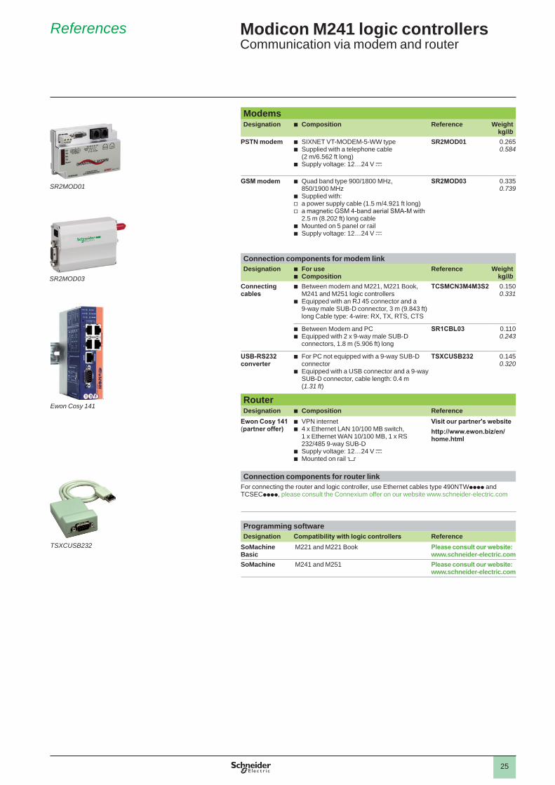
ModemsDesignation b Composition Reference Weight
kg/lbPSTN modem b SIXNET VT-MODEM-5-WW type
b Supplied with a telephone cable (2 m/6.562 ft long)
b Supply voltage: 12…24 V c
SR2MOD01 0.2650.584
GSM modem b Quad band type 900/1800 MHz, 850/1900 MHz
b Supplied with: v a power supply cable (1.5 m/4.921 ft long) v a magnetic GSM 4-band aerial SMA-M with 2.5 m (8.202 ft) long cable
b Mounted on 5 panel or rail b Supply voltage: 12…24 V c
SR2MOD03 0.3350.739
Connection components for modem linkDesignation b For use
b CompositionReference Weight
kg/lbConnecting cables
b Between modem and M221, M221 Book, M241 and M251 logic controllers
b Equipped with an RJ 45 connector and a 9-way male SUB-D connector, 3 m (9.843 ft) long Cable type: 4-wire: RX, TX, RTS, CTS
TCSMCN3M4M3S2 0.1500.331
b Between Modem and PC b Equipped with 2 x 9-way male SUB-D connectors, 1.8 m (5.906 ft) long
SR1CBL03 0.1100.243
USB-RS232 converter
b For PC not equipped with a 9-way SUB-D connector
b Equipped with a USB connector and a 9-way SUB-D connector, cable length: 0.4 m (1.31 ft)
TSXCUSB232 0.1450.320
Router Designation b Composition Reference
Ewon Cosy 141(partner offer)
b VPN internet b 4 x Ethernet LAN 10/100 MB switch, 1 x Ethernet WAN 10/100 MB, 1 x RS 232/485 9-way SUB-D
b Supply voltage: 12…24 V c b Mounted on rail 5
Visit our partner's websitehttp://www.ewon.biz/en/home.html
Connection components for router linkFor connecting the router and logic controller, use Ethernet cables type 490NTWpppp and TCSECpppp, please consult the Connexium offer on our website www.schneider-electric.com
Programming softwareDesignation Compatibility with logic controllers Reference
SoMachine Basic
M221 and M221 Book Please consult our website: www.schneider-electric.com
SoMachine M241 and M251 Please consult our website: www.schneider-electric.com
SR2MOD01
SR2MOD03
Ewon Cosy 141
TSXCUSB232

26
Compatibility Modicon M241 logic controllersCompatibility of Modicon TM2 expansion modules with Modicon M241 logic controllers
Compatibility Modicon TM2 expansion modules Logic controllers
M221 M221 Book M241 M251
Digital modules TM2DDI8DTTM2DDI16DTTM2DDI16DKTM2DDI32DK TM2DAI8DTTM2DDO8UTTM2DDO8TTTM2DDO16UKTM2DDO16TKTM2DDO32UKTM2DDO32TKTM2DRA8RTTM2DRA16RTTM2DMM8DRTTM2DMM24DRF
Analog modules TM2AMI2HTTM2AMI2LTTM2AMI4LTTM2AMI8HTTM2ARI8LRJTM2ARI8LTTM2ARI8HTTM2AMO1HTTM2AVO2HTTM2AMM3HTTM2ALM3LTTM2AMM6HT
Expert modules (counter modules)
TM200HSC206DTTM200HSC206DF
Compatible
Not compatible
Note: The TWDppppp range of expansion and communication modules is not compatible with the Modicon M221/M221 Book/M241/M251 logic controller offer.
Configuration b Modicon TM3 expansion modules are powered by logic controllers via the bus
connector on the side of the products. This connector delivers 2 voltages, 5 V and 24 V. For the Modicon M221 and M221 Book logic controllers, you should therefore calculate the total TM3 expansion module consumption and check that it is definitely compatible with the maximum current delivered by the controller. This information is available on each product data sheet or in the hardware reference guide. This can be checked very quickly in the SoMachine Basic programming software setup page.
b For Modicon M241 and M251 logic controllers, up to 7 TM2 expansion modules can be attached regardless of these module references.

27
Modicon M241 logic controllersProduct reference index
Index
4490NTW00002 23490NTW00002U 23490NTW00005 23490NTW00005U 23490NTW00012 23490NTW00012U 23490NTW00040 23490NTW00040U 23490NTW00080 23490NTW00080U 23
BBMXXCAUSBH018 11
LLU9GC3 15
SSR1CBL03 25SR2MOD01 25SR2MOD03 25
TTCSCAR013M120 17TCSCAR01NM120 17TCSCCN4F3M05T 17TCSCCN4F3M1T 17TCSCCN4F3M3T 17TCSCTN023F13M03 17TCSCTN026M16M 17TCSECE3M3M10S4 23TCSECE3M3M1S4 23TCSECE3M3M2S4 23TCSECE3M3M3S4 23TCSECE3M3M5S4 23TCSECN300R2 23TCSECU3M3M10S4 23TCSECU3M3M1S4 23TCSECU3M3M2S4 23TCSECU3M3M3S4 23TCSECU3M3M5S4 23TCSEK3MDS 23TCSESU033FN0 23TCSESU043F1N0 23TCSESU053FN0 23TCSMCN3M4F3C2 15TCSMCN3M4M3S2 15
25TCSXCNAMUM3P 11TLACDCBA005 17TLACDCBA015 17TLACDCBA030 17TLACDCBA050 17TM241C24R 10TM241C24T 10TM241C24U 10TM241C40R 10TM241C40T 10TM241C40U 10TM241CE24R 10TM241CE24T 10TM241CE24U 10
TM241CE40R 10TM241CE40T 10TM241CE40U 10TM241CEC24R 10TM241CEC24T 10TM241CEC24U 10TM4ES4 13TM4PDPS1 13TMASD1 10TMAT2PSET 11TMAT4CSET 11TMC4AI2 10TMC4AQ2 10TMC4HOIS01 10TMC4PACK01 10TMC4TI2 10TSXCANCA100 17TSXCANCA300 17TSXCANCA50 17TSXCANCADD03 17TSXCANCADD1 17TSXCANCADD3 17TSXCANCADD5 17TSXCANCB100 17TSXCANCB300 17TSXCANCB50 17TSXCANCBDD03 17TSXCANCBDD1 17TSXCANCBDD3 17TSXCANCBDD5 17TSXCANCD100 17TSXCANCD300 17TSXCANCD50 17TSXCANKCDF90T 17TSXCANKCDF180T 17TSXCANKCDF90TP 17TSXCANTDM4 17TSXCSA100 15TSXCSA200 15TSXCSA500 15TSXCUSB232 25TSXSCA50 15TWDXCAFJ010 15TWDXCAISO 14TWDXCAT3RJ 14
VVW3A8306D30 15VW3A8306R03 15VW3A8306R10 15VW3A8306R30 15VW3A8306RC 15VW3A8306TF03 15VW3A8306TF10 15VW3CANA71 17VW3CANCARR03 17VW3CANCARR1 17VW3CANTAP2 17VW3M3805R010 17VW3M3805R030 17
XXBTZ9008 15XBTZ938 15
XBTZ9980 15XBTZ9982 15XGSZ24 15

The information provided in this documentation contains general descriptions and/or technical characteristics of the performance of the products contained herein. This documentation is not intended as a substitute for and is not to be used for determining suitability or reliability of these products for specific user applications. It is the duty of any such user or integrator to perform the appropriate and complete risk analysis, evaluation and testing of the products with respect to the relevant specific application or use thereof. Neither Schneider Electric nor any of its affiliates or subsidiaries shall be responsible or liable for misuse of the information contained herein.
Design: Schneider ElectricPhotos: Schneider Electric
Head Office35, rue Joseph MonierF-92500 Rueil-MalmaisonFrance
Schneider Electric Industries SAS www.schneider-electric.com/msx
October 2016 - V3.0 DIA
3ED
2140
107E
N


![[XLS] 20120720 Ryasa2.xlsx · Web viewBRIDA BPX-60 010603DOD BRIDA BPX-70 010604DOD BRIDA P/COPLE PX-80 010605DOD MAZA PARA COPLE PX-90 010606 DOD BRIDA BPX100 010608DOD BRIDA BPX-120](https://static.fdocuments.us/doc/165x107/5b4d62927f8b9ac9758b71cd/xls-20120720-ryasa2xlsx-web-viewbrida-bpx-60-010603dod-brida-bpx-70-010604dod.jpg)