Catalog News IC 10 N · April 2013, English · Siemens IC 10 N · 04/2013 5 Technical Assistance....
90
SIRIUS Industrial Controls SIRIUS Product News - Hannover Messe 2013 Answers for industry. Catalog News IC 10 N Edition April 2013 © Siemens AG 2013
Transcript of Catalog News IC 10 N · April 2013, English · Siemens IC 10 N · 04/2013 5 Technical Assistance....

SIRIUS
Industrial ControlsSIRIUS Product News - Hannover Messe 2013
Answers for industry.
CatalogNewsIC 10 N
EditionApril2013
IC10N_201304_umschlag_ENG.indd 1IC10N_201304_umschlag_ENG.indd 1 17.05.2013 09:56:4717.05.2013 09:56:47
© Siemens AG 2013

Registered trademarksAll product designations may be registered trademarks or product names of Siemens AG or other supplying companies. Third parties using these trademarks or product names for their own purposes may infringe upon the rights of the trademark owners.
Further information about industrial controls:www.siemens.com/sirius
Related catalogs Other information
Registered trademarks Technical Assistance
Industrial Controls IC 10SIRIUS
E86060-K1010-A101-A2-7600
Industrial Controls IC 10 NSIRIUS News
E86060-K1010-A221-A1-7600
Low-Voltage Power Distribution and LV 10.1Electrical Installation Technology SENTRON Protection, Switching, Measuring and Monitoring Devices
E86060-K8250-A101-A3-7600
Safety Integrated SI 10Safety Technology forFactory Automation
E86060-K7010-A101-A2-7600
Industrial Communication IK PISIMATIC NET
E86060-K6710-A101-B7-7600
SIMATIC ST 70Products forTotally Integrated Automation and Micro Automation
E86060-K4670-A101-B4-7600
SIMOTICS Low-Voltage Motors D 81.1Frame sizes 63 to 450Power 0.09 to 1250 kW
E86060-K5581-A111-A4-7600
SITRAIN ITCTraining for Automation and Industrial Solutions
Only available in GermanE86060-K6850-A101-C3
Products for Automation CA 01and DrivesInteractive Catalog
DVD: E86060-D4001-A510-D2-7600
Industry MallInformation and Ordering Platformin the Internet:
www.siemens.com/industrymall
Information and Download CenterDigital versions of the catalogs are available in the Internet
www.siemens.com/sirius/catalogs
Response E-mailPlease send your comments and suggestions for improvement [email protected] (include the catalog name in the subject field)
Technical AssistanceExpert technical assistance for Industrial controls:Tel.: +49 (911) 895-5900Fax: +49 (911) 895-5907
E-Mail: [email protected]
U2_IC10N_2013_en.fm Seite 1 Montag, 13. Mai 2013 12:08 12
© Siemens AG 2013

SIRIUSIndustral Controls
Catalog IC 10 N · 04/2013
Refer to the Industry Mall for current updates of this catalog: www.siemens.com/industrymall
The products contained in this catalog can also be found in the interactive catalog CA 01. Order No. E86050-D4001-A510-D2-7600 (DVD)
Please contact your local Siemens branch
© Siemens AG 2013
The products and sys-tems described in this catalog are manufac-tured/distributed under application of a certified quality management system in accordance with DIN EN ISO 9001 (for the Certificate Regis-ter Nos. see the Appen-dix to the catalog IC 10). The certificate is recog-nized by all IQNet coun-tries.
Introduction 1
Industrial Communication 2
Controls – Contactors and Contactor Assemblies – for Switching Motors
3
Controls – Contactors and Contactor Assemblies – Special Applications
4
Controls – Contactors and Contactor Assemblies – Contactor Relays and Relays
5
Controls – Soft Starters and Solid-State Switching Devices
6
Protection Equipment 7
Load Feeders and Motor Starters for Use in the Control Cabinet
8
Motor Starters for Use in the Field, High Degree of Protection
9
Monitoring and Control Devices 10
Safety Technology 11
Position and Safety Switches 12
Commanding and Signaling Devices 13
Parametrization, Configuration and Visualization with SIRIUS
14
Products for Specific Requirements 15
Appendix 16
IC10N_00_01_InnerTitle.fm Seite 1 Freitag, 17. Mai 2013 11:50 11
© Siemens AG 2013

2 Siemens IC 10 N · 04/2013
NEW
CM AS-i Master STcommunication module for ET 200SP
Order No.: 3RK7137-6SA00-0BC1
Page 2/7
AS-Interface digital I/O modules IP67 - K60for use in the field, high degree of protection
Order No.: 3RK2200-0CQ00-0AA3, 3RK2100-1CQ00-0AA3
Page 2/11
AS-Interface digital I/O modules IP67 - K45for use in the field, high degree of protection
Order No.: 3RK2200-0DQ20-0AA3, 3RK2100-1CQ20-0AA3
Page 2/13
30 V power supply unitsfor AS-Interface
Order No.: 3RX9511-0AA00, 3RX9512-0AA00, 3RX9513-0AA00
Page 2/15
IO-Link Master CM 4xIO-Linkcommunication module for ET 200SP
Order No.: 6ES7137-6BD00-0BA0
Page 2/23
SIRIUS 3UG46 residual current monitoring devices
Order No.: 3UG4625-.CW30
Pages 10/6
SIRIUS_IC10N_German_2013-04.book Seite 2 Freitag, 17. Mai 2013 10:32 10
© Siemens AG 2013
3Siemens IC 10 N · 04/2013
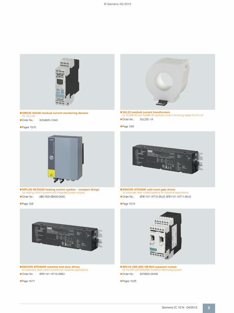
SIRIUS 3UG48 residual current monitoring devices for IO-Link
Order No.: 3UG4825-.CA40
Pages 10/15
3UL23 residual current transformersfor 3UG46 25 and 3UG48 25 residual-current monitoring relays for IO-Link
Order No.: 3UL230.-1A
Page 10/9
SIPLUS HCS3200 heating control system – compact designfor heating control systems with integrated power outputs
Order No.: 6BK1932-0BA00-0AA0
Page 15/6
SIDOOR ATD400K cold room gate drivesfor automatic door control systems for industrial applications
Order No.: 6FB1141-1AT10-3KU2, 6FB1141-1AT11-3KU2
Page 15/14
SIDOOR ATD400W machine tool door drivesfor automatic door control systems for industrial applications
Order No.: 6FB1141-1AT10-3WE2
Page 15/17
SIPLUS CMS 2000 VIB-MUX expansion modulefor the SIPLUS CMS2000 Condition Monitoring System
Order No.: 6AT8002-2AA00
Pages 15/25
SIRIUS_IC10N_German_2013-04.book Seite 3 Freitag, 17. Mai 2013 10:32 10
© Siemens AG 2013

4 Siemens IC 10 N · 04/2013
SIRIUS_IC10N_German_2013-04.book Seite 4 Freitag, 17. Mai 2013 10:32 10
© Siemens AG 2013

5Siemens IC 10 N · 04/2013
Technical Assistance.
Our Technical Assistance for Industrial Controls will help you
with all technical enquiries concerning our products and systems
– both before and after delivery.
Our experts will provide you with spe-cialist support over the phone in con-nection with:
• Product selection• Conversion from old to new codes• Conversion from non-Siemens
codes• Special versions• Special requirements• Commissioning• Operation
To ensure that you always speak with the right person, our telephone assis-tance system comes in two steps. In the first step we note your questions and forward them to the right contact per-son.
In the second step your personal con-tact then phones you back.
This way you receive an expert answer quickly and easily.
Contact data
Technical Assistance
Tel.: +49 (911) 895 5900
Fax: +49 (911) 895 5907
E-Mail: [email protected]
Technical Support on the Internet
www.siemens.com/sirius/support
Support Request on the Internet
www.siemens.com/automation/support-request .
SIRIUS_IC10N_German_2013-04.book Seite 5 Freitag, 17. Mai 2013 10:32 10
© Siemens AG 2013
6 Siemens IC 10 N · 04/2013
SIRIUS_IC10N_German_2013-04.book Seite 6 Freitag, 17. Mai 2013 10:32 10
© Siemens AG 2013

7Siemens IC 10 N · 04/2013
Answers for industry.
Integrated technologies, vertical market expertise and services
for greater productivity, energy efficiency, and flexibility.
The Siemens Industry Sector is the world's leading supplier of innovative and environmentally friendly products and solutions for industrial companies. End-to-end automation technology and industrial software, solid market exper-tise, and technology-based services are the levers we use to increase our cus-tomers’ productivity, efficiency and flexibility. With a global workforce of more than 100 000 employees, the Industry Sector comprises the Industry Automation, Drive Technolo-gies, and Customer Services divisions, as well as the Metals Technologies Business Unit.
We consistently rely on integrated tech-nologies and, thanks to our bundled portfolio, we can respond more quickly and flexibly to our customers' wishes. With our globally unmatched range of automation technology, industrial con-trol and drive technology as well as industrialsoftware, we equip companies with exactly what they need over their entire valuechain – from product design and development to production, sales and service. Our industrial customers benefit from our comprehensive portfo-lio, which is tailored to their market and their needs.
Market launch times can be reduced by up to 50% due to the combination of powerfulautomation technology and in-telligent industrial software from Siemens Industry. At the same time, the costs for energy or waste water for a manufacturing company can be re-duced significantly. In this way, we in-crease our customers’ competitive strength and make an important contri-bution to environmental protection with our energy-efficient products and solutions.
© Siemens AG 2013

8 Siemens IC 10 N · 04/2013
Setting standards in productivity and competitiveness.Totally Integrated Automation.
SIRIUS_IC10N_German_2013-04.book Seite 8 Freitag, 17. Mai 2013 10:32 10
© Siemens AG 2013

9Siemens IC 10 N · 04/2013
Thanks to Totally Integrated Automation, Siemens provides
an integrated basis for the implementation of customized
automation solutions – in all industries from inbound to
outbound.
TIA is characterized by its unique continuity.
It provides maximum transparency at all levels with reduced interfacing requirements – covering the field level, production control level, up to the corporate management level. With TIA you also profit throughout the complete life cycle of your plant – starting with the initial planning steps through operation up to modernization, where we offer a high measure of investment security re-sulting from continuity in the further development of our products and from reducing the number of interfaces to a minimum.
The unique continuity is already a defined characteristic at the development stage of our products and systems.
The result: maximum interoperability – covering the controller, HMI, drives, up to the process control system. This reduces the complexity of the automation solution in your plant. You will experience this, for example, in the engineering phase of the automation solution in the form of reduced time requirements and cost, or during operation using the continuous diagnostics facili-ties of Totally Integrated Automation for increas-ing the availability of your plant.
SIRIUS_IC10N_German_2013-04.book Seite 9 Freitag, 17. Mai 2013 10:32 10
© Siemens AG 2013

10 Siemens IC 10 N · 04/2013
Notes
SIRIUS_IC10N_German_2013-04.book Seite 10 Freitag, 17. Mai 2013 10:32 10
© Siemens AG 2013
Siemens IC 10 N · 04/2013
2
Siemens IC 10 N · 04/2013
2
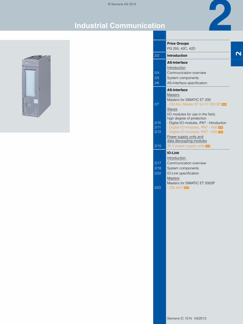
Price GroupsPG 255, 42C, 42D
2/2 Introduction
AS-InterfaceIntroduction
2/4 Communication overview2/5 System components2/6 AS-Interface specification
AS-InterfaceMastersMasters for SIMATIC ET 200
2/7 - CM AS-i Master ST for ET 200 SP SlavesI/O modules for use in the field, high degree of protection
2/10 - Digital I/O modules, IP67 - Introduction2/11 - Digital I/O modules, IP67 - K60 2/13 - Digital I/O modules, IP67 - K45
Power supply units anddata decoupling modules
2/15 30 V power supply units
IO-LinkIntroduction
2/17 Communication overview2/18 System components2/22 IO-Link specification
MastersMasters for SIMATIC ET 200SP
2/23 - CM 4xIO
new
new
new
new
new
Industrial Communication
SIRIUS_IC10N_German_2013-04.book Seite 1 Freitag, 17. Mai 2013 10:32 10
© Siemens AG 2013

Industrial Communication
Introduction
2/2 Siemens IC 10 N · 04/2013
2
■ Overview
Order No. Page
AS-Interface: MastersThe AS-Interface master connects industrial control systems to AS-Interface. It automatically organizes the data traffic on the AS-Interface cable and sees not only to processing the sig-nals but also to performing the parameter setting, monitoring and diagnostics functions.
CM AS-i Master ST for SIMATIC ET 200SP
Masters for SIMATIC ET 200
CM AS-i Master ST for SIMATIC ET 200SP
• Connection of up to 62 AS-Interface slaves per master
• Connection of up to 496 inputs and 496 outputs per AS-Interface network
• Simple configuration by adopting the actual configuration on the AS-Interface network at the press of a button
• Easy operation in the input/output address area of the SIMATIC (or other controller) com-parable to standard I/O modules
• Monitoring of the control supply voltage on the AS-Interface shaped cable
Your advantage: Easy connection of AS-i networks to distributed I/Os
3RK7 2/7
AS-Interface: SlavesSlaves contain the AS-Interface electronics and connection options for sensors and actua-tors in the field and in the control cabinet. A total of up to 62 slaves can be connected to one bus. The slaves then exchange their data in cyclic mode with a control module (master).
K60 digital module
K45 digital module
I/O modules for use in the field, high degree of protection
New digital I/O modules IP67 - K60 and K45
• Degree of protection IP65/IP67
• Connection sockets in M8/M12
• Up to eight inputs and four outputs
• A/B technology available
• Contacting protected against polarity reversal
• Standard rail mounting and wall mounting possible
• Mounting of the module on the base plate using just one screw
• Diagnostics LEDs
Your advantage: Reduction of mounting and start-up times by up to 40 %
3RK2 2/11
AS-Interface: Power supply units and data decoupling modulesAS-Interface power supply units generate a controlled direct voltage of 30 V DC with high stability and low residual ripple in conjunction with data decoupling. They are an integral component of the AS-Interface network and enable the simultaneous transmission of data and energy on one cable.
In conjunction with data decoupling modules, AS-Interface can also be operated with stan-dard power supply units.
PSN130S 30 V DC, 8 A
30 V power supply units
Standard 30 V power supply units without data decoupling
• Power spectrum 3 A, 4 A and 8 A
• Overload and short-circuit proof in every performance class
• Diagnostics: With output voltage > 26.5 V DCLED and signaling contact for output voltage 30V O.K.
• Primary-side connection to 120 V AC / 230 V AC (1-phase) with automatic range selection
Your advantage: Economical alternatives in conjunction with data decoupling modules while making full use of the maximum AS-Interface cable length also for multiple networks
3RX9 2/15
SIRIUS_IC10N_German_2013-04.book Seite 2 Freitag, 17. Mai 2013 10:32 10
© Siemens AG 2013

Industrial Communication
2/3Siemens IC 10 N · 04/2013
Introduction
2
Note:
Order No. Page
IO-Link IO-Link is an open communication standard for sensors and actuators - defined by the Profibus User Organization (PNO).
IO-Link family
• Dynamic changing of sensor/actuator parameters directly by the PLC
• Devices can be exchanged during operation, without a PC or programming device, through re-parameterization using the user program by means of a function block (FB) or parameter server
• Fast commissioning thanks to central data storage
• Consistent diagnostic information as far as the sensor/actuator level
• Uniform and greatly reduced wiring of different sensors/actuators/controls
Your advantage: Fast commissioning and flexible maintenance thanks to central data storage, less wiring work because no passive distributors are needed
2/18
IO-Link: MastersThe IO-Link master modules form the heart of the IO-Link system.
CM 4x IO-Linkfor ET 200SP
IO-Link master modules for ET 200SP
CM 4xIO-Link electronic module
• IO-Link master as serial communication module with 4 ports (channels) according to IO-Link Specification V1.1
• Module exchange with automatic data recovery without engineering for IO-Link master and device
• Up to four IO-Link devices (3-wire connections) can be connected to each IO-Link master module.
• Data transmission rates COM1 (4.8 kBit/s), COM2 (38.4 kBit/s), COM3 (230.4 kBit/s), automatic adjustment to the data rate supported by the device
Your advantage: Easy connection of IO-Link connections to distributed I/Os
6ES7 2/23
Screw terminals
Spring-type terminals
Combicon connectors (plug-in screw terminals)
FastConnect
The terminals are indicated in the selection and order-ing data by orange backgrounds.
SIRIUS_IC10N_German_2013-04.book Seite 3 Freitag, 17. Mai 2013 10:32 10
© Siemens AG 2013

AS-InterfaceIntroduction
Communication overview
2/4 Siemens IC 10 N · 04/2013
2
■ Overview
AS-Interface is an open, international standard according to EN 50295 and IEC 62026-2 for process and field communication. Leading manufacturers of actuators and sensors all over the world support the AS-Interface. Interested companies are pro-vided with the electrical and mechanical specifications by the AS-Interface Association.
AS-Interface is a single master system. For automation systems from Siemens, there are communications processors (CPs) com-munications modules (CMs) and routers (links) that control the process or field communication as masters, and actuators and sensors that are activated as AS-Interface slaves.
■ Benefits
A key feature of AS-Interface technology is the use of a shared two-conductor cable for data transmission and the distribution of auxiliary power to the sensors/actuators. A power supply unit which meets the requirements of the AS-Interface transmission method and has an external data decoupling module if required is used for the distribution of auxiliary power. The AS-Interface cable used for the wiring is mechanically coded and hence pro-tected against polarity reversal and can be easily contacted by the insulation piercing method.
Elaborately wired control cables in the control cabinet and mar-shalling racks can be replaced by AS-Interface.
The AS-Interface cable can be connected to any points thanks to a specially developed cable and connection by the insulation piercing method.
With this concept you become extremely flexible and achieve high savings.
■ Application
I/O data exchange
The AS-i master transmits automatically the inputs and outputs between the control system and the digital and analog AS-Interface slaves.
Slave diagnostics information is forwarded to the control system when required.
AS-Interface masters according to the AS-Interface Specifica-tion V2.1 or V3.0 support integrated analog value processing. This means that data exchange with analog AS-Interface slaves is just as easy as with digital slaves.
Command interface
In addition to I/O data exchange with binary and analog AS-Interface slaves the AS-Interface masters provide a number of other functions through the command interface.
Hence it is possible, for example, for slave addresses to be is-sued, parameter values transferred or configuration information read out from user programs.
You can find more information on the Internet, see http://support.automation.siemens.com/WW/view/en/51678777
Control andmonitoring system
Telecontrol and substation control
Remote access, e.g. via teleservice
Field device for intrinsically safe area
Coupler
Sensors
Field devices
Sensors Compactstarter
Compactstarter
Compactfeeder Field device
Power supply
Signalling column
Powersupply
1200
1242 7
Compactstarter
Protection and monitoring devices
PC/PG/IPC
PROFIBUS PA
Laptop
Motion ControlSystems
Notebook
SINAMICS
SIMOCODE
ASM456
PC
Security
AccessPoint
Link
AccessPoint
IWLAN
Database Server
ModuleControllerLOGO!
Slaves Slaves
AS-Interface
Link
AccessPoint
Link
Control andmonitoring system
Telecontrol and substation control
Remote access, e.g. via teleservice
Field device for intrinsically safe area
Coupler
Sensors
Field devices
Sensors Compactstarter
Field device
1200
1242 7
Compactstarter
Protection and monitoring devices
PC/PG/IPC
PROFIBUS PA
Laptop
Motion ControlSystems
Notebook
SINAMICS
SIMOCODE
ASM456
PC
Security
AccessPoint
Link
AccessPoint
IWLAN
Database Server
Module
AccessPoint
Link
G_I
K10
_XX
_200
02
SIRIUS_IC10N_German_2013-04.book Seite 4 Freitag, 17. Mai 2013 10:32 10
© Siemens AG 2013

AS-InterfaceIntroduction
2/5Siemens IC 10 N · 04/2013
System components
2
■ Overview
To implement communication, a system installation has the fol-lowing main components: • Master interface modules for central control units such as SI-
MATIC S7, ET 200 distributed peripherals, or routers from PROFIBUS/PROFINET to AS-Interface
• Power supply units, if required in combination with a data de-coupling module for the power supply to the slaves
• AS-Interface shaped cables
• Network components such as repeaters and extension plugs (cannot be used for AS-i Power24V)
• Modules for connection of standard sensors/actuators• Actuators and sensors with integrated AS-i slave• Safety modules for transmitting safety-oriented data through
AS-Interface• Addressing units for setting the slave addresses during com-
missioning
Example of a configuration with the system components
Features
24 V DCpower supply
AS-Interfacepower supply
AS-Interfacepower supply
Digital and analog K20, K45, K60 field modules
Safe position switch with door interlock
3RA2 load feeders
3RA6 compact starters
SIRIUS M200D motor starters or G110D frequency converters
Load feeders with safe AS-i outputs
Safe EMERGENCY-STOP and field module
Signaling columns
Pushbuttons Indicator lights
Safe and standard control cabinet modules S22.5 and S45
S7-1200 with CM 1243-2
DP/AS-i F-Link
SIMATIC/SIMOTION
DP/AS-i Link AdvancedDP/AS-i Link 20E
S7-300CP343-2(P)
PROFINET
AS-Interface
Industrial EthernetPROFIBUS DP
IE/AS-i Link PN IO
G_I
K10
_XX
_200
27j
S7-300CP343-2(P)
CM AS-i Master für ET 200SP
S7-200mit CP243-2
MSS ASIsafe
MSS Advanced
SINUMERIK
Standard EN 50295 / IEC 62026-2
Topology Line, star or tree structure (same as electrical wiring)
Transmission medium Unshielded two-wire cable (2 x 1.5 mm2) for data and auxiliary power
Connection methods Contacting of the AS-Interface cable by insulation piercing method
Maximum cable length • 100 m without repeater• 200 m with extension plug • 300 m with two repeaters in series connection • 600 m with extension plugs and two repeaters
connected in parallel Larger cable lengths are also possible when additional repeaters are connected in parallel
Maximum cycle time • 5 ms in full expansion with standard addresses• 10 ms in full expansion with A/B addresses,
profile-specific for Spec 3.0 slaves
Number of stations per AS-Interface line
• 31 slaves acc. to AS-Interface Spec. V2.0• 62 slaves (A/B technology) acc. to
AS-Interface Spec. V2.1 and V3.0• Integrated analog value transmission
Number of binary sensors and actuators
• Max. 124 DI/124 DO according to Spec. V2.0• Max. 248 DI/186 DO according to Spec. V2.1• Max. 496 DI/496 DO according to Spec. V3.0
Access control • Cyclic polling master/slave procedure• Cyclic data acceptance from host (PLC, PC)
Error safeguard Identification and repetition of faulty message frames
SIRIUS_IC10N_German_2013-04.book Seite 5 Freitag, 17. Mai 2013 10:32 10
© Siemens AG 2013
AS-InterfaceIntroductionAS-Interface specificationSpecification 2.0, 2.1 and 3.0
2/6 Siemens IC 10 N · 04/2013
2
■ Overview
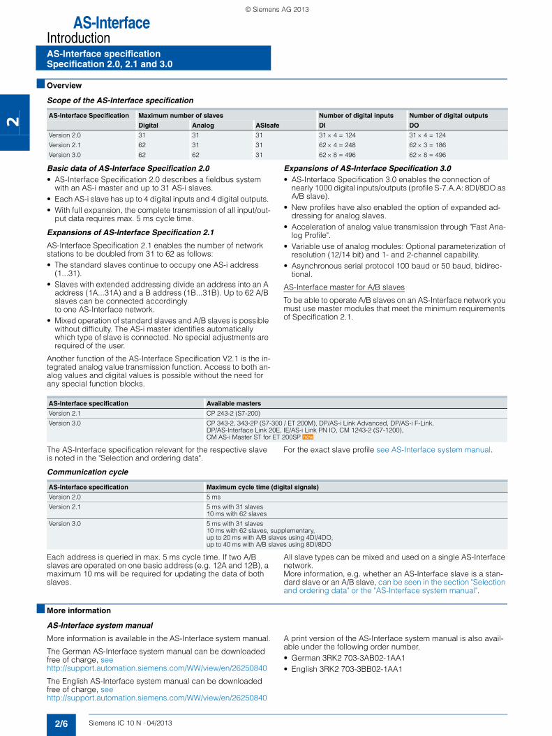
Scope of the AS-Interface specification
Basic data of AS-Interface Specification 2.0• AS-Interface Specification 2.0 describes a fieldbus system
with an AS-i master and up to 31 AS-i slaves. • Each AS-i slave has up to 4 digital inputs and 4 digital outputs. • With full expansion, the complete transmission of all input/out-
put data requires max. 5 ms cycle time.
Expansions of AS-Interface Specification 2.1
AS-Interface Specification 2.1 enables the number of network stations to be doubled from 31 to 62 as follows: • The standard slaves continue to occupy one AS-i address
(1...31). • Slaves with extended addressing divide an address into an A
address (1A...31A) and a B address (1B...31B). Up to 62 A/B slaves can be connected accordingly to one AS-Interface network.
• Mixed operation of standard slaves and A/B slaves is possible without difficulty. The AS-i master identifies automatically which type of slave is connected. No special adjustments are required of the user.
Another function of the AS-Interface Specification V2.1 is the in-tegrated analog value transmission function. Access to both an-alog values and digital values is possible without the need for any special function blocks.
Expansions of AS-Interface Specification 3.0• AS-Interface Specification 3.0 enables the connection of
nearly 1000 digital inputs/outputs (profile S-7.A.A: 8DI/8DO as A/B slave).
• New profiles have also enabled the option of expanded ad-dressing for analog slaves.
• Acceleration of analog value transmission through "Fast Ana-log Profile".
• Variable use of analog modules: Optional parameterization of resolution (12/14 bit) and 1- and 2-channel capability.
• Asynchronous serial protocol 100 baud or 50 baud, bidirec-tional.
AS-Interface master for A/B slaves
To be able to operate A/B slaves on an AS-Interface network you must use master modules that meet the minimum requirements of Specification 2.1.
The AS-Interface specification relevant for the respective slave is noted in the "Selection and ordering data".
For the exact slave profile see AS-Interface system manual.
Communication cycle
Each address is queried in max. 5 ms cycle time. If two A/B slaves are operated on one basic address (e.g. 12A and 12B), a maximum 10 ms will be required for updating the data of both slaves.
All slave types can be mixed and used on a single AS-Interface network.More information, e.g. whether an AS-Interface slave is a stan-dard slave or an A/B slave, can be seen in the section "Selection and ordering data" or the "AS-Interface system manual".
■ More information
AS-Interface system manual
More information is available in the AS-Interface system manual.
The German AS-Interface system manual can be downloaded free of charge, see http://support.automation.siemens.com/WW/view/en/26250840
The English AS-Interface system manual can be downloaded free of charge, see http://support.automation.siemens.com/WW/view/en/26250840
A print version of the AS-Interface system manual is also avail-able under the following order number. • German 3RK2 703-3AB02-1AA1• English 3RK2 703-3BB02-1AA1
AS-Interface Specification Maximum number of slaves Number of digital inputs Number of digital outputs
Digital Analog ASIsafe DI DO
Version 2.0 31 31 31 31 × 4 = 124 31 × 4 = 124
Version 2.1 62 31 31 62 × 4 = 248 62 × 3 = 186
Version 3.0 62 62 31 62 × 8 = 496 62 × 8 = 496
AS-Interface specification Available masters
Version 2.1 CP 243-2 (S7-200)
Version 3.0 CP 343-2, 343-2P (S7-300 / ET 200M), DP/AS-i Link Advanced, DP/AS-i F-Link, DP/AS-Interface Link 20E, IE/AS-i Link PN IO, CM 1243-2 (S7-1200), CM AS-i Master ST for ET 200SP new
AS-Interface specification Maximum cycle time (digital signals)
Version 2.0 5 ms
Version 2.1 5 ms with 31 slaves 10 ms with 62 slaves
Version 3.0 5 ms with 31 slaves10 ms with 62 slaves, supplementary, up to 20 ms with A/B slaves using 4DI/4DO, up to 40 ms with A/B slaves using 8DI/8DO
SIRIUS_IC10N_German_2013-04.book Seite 6 Freitag, 17. Mai 2013 10:32 10
© Siemens AG 2013

AS-InterfaceMasters
2/7Siemens IC 10 N · 04/2013
Master for SIMATIC ET 200CM AS-i Master for ET 200 SP
2
■ Overview
CM AS-i Master ST for SIMATIC ET 200 SP
The CM AS-i Master ST communication module is designed for use in the SIMATIC ET 200SP distributed I/O system and has the following features:• Connection of up to 62 AS-Interface slaves• Supports all AS-Interface master functions according to the
AS-Interface Specification V3.0• User-friendly configuration with graphic display of the AS-i line
in TIA Portal V12.0 or in other systems by using GSD• Supply via AS-Interface cable• Suitable for AS-i Power24V and for AS-Interface with 30 V volt-
age• Integrated ground-fault monitoring for the AS-Interface cable• Through connection to AS-Interface and in combination with
ET 200 SP, the number of digital inputs and outputs available for the control system is greatly increased (max. 496 DI / 496 DO on the AS-Interface per CM).
• Integrated analog value processing (all analog profiles)
Basic unit: ET 200SP distributed I/O system
The SIMATIC ET 200SP distributed I/O system is a scalable and highly flexible I/O system for connecting the process signals to a central control system via PROFINET.
Up to eight CM AS-i Master STs can be plugged into a SIMATIC ET200SP with IM 155-6 PN ST standard interface module.
For more information see "ET 200SP System Manual" at
http://support.automation.siemens.com/WW/view/en/58649293
DesignThe CM AS-i Master ST has an ET 200SP module enclosure with a width of 20 mm. A BaseUnit is required for use in the ET 200SP. The CM AS-i Master ST can be plugged onto type C0 BaseUnits (BU) with automatic coding.The CM AS-i Master ST has LED indicators for diagnostics, op-eration, AS-i voltage and AS-i slave status.The CM AS-i Master ST offers informative front-side module in-scription for• Plain-text marking of the module type and function class• 2D matrix code (order number and serial number)• Circuit diagram• Color coding of the CM module type: Blue• Hardware and firmware version• Complete order number
FunctionThe CM AS-i Master ST supports all specified functions of the AS-Interface Specification V3.0.The input/output values of the digital AS-i slaves can be acti-vated via the cyclic process image. The values of the analog AS-i slaves can be reached via data record transfer.If required, master calls can be performed with the command in-terface, e.g. read/write parameters, read/write configuration.Changeover of the operating mode, automatic application of the slave configuration and the re-addressing of a connected AS-i slave can be implemented via the control panel of the CM AS-i Master ST in the TIA Portal.
Notes on safety
The use of this product requires suitable protective measures (e.g. network segmentation for IT security among others) in or-der to ensure safe plant operation, see www.siemens.com/industrialsecurity.
ConfigurationConfiguration of the CM AS-i Master ST requires TIA Portal V12 or the GSD file.The TIA Portal enables user-friendly configuration and diagnos-tics of the AS-i master and any connected slaves.Alternatively, you can also apply the AS-Interface ACTUAL con-figuration as the DESIRED configuration at the "touch of a button" via the control panel integrated in the TIA Portal or an optional expansion button. Configuration with the GSD file is possible only with the button.
Configuration of an AS-Interface network with CM AS-i Master ST via TIA Portal
SIRIUS_IC10N_German_2013-04.book Seite 7 Freitag, 17. Mai 2013 10:32 10
© Siemens AG 2013

AS-InterfaceMastersMaster for SIMATIC ET 200CM AS-i Master for ET 200 SP
2/8 Siemens IC 10 N · 04/2013* You can order this quantity or a multiple thereof.
Illustrations are approximate
2
■ Benefits
The CM AS-i Master ST for ET 200SP enables modular, easy and high-performance expansion of AS-Interface networks via engi-neering in the TIA Portal.
Up to eight CM AS-i masters can be plugged into one ET 200SP station, depending on the interface module used. Multiple mas-ters as well as single masters can be implemented in the ET 200SP depending on the number of modules.
Together with the interface module, a scalable PROFINET/AS-i Link can be assembled.
■ Application
Configuration examples of AS-Interface networks with CM AS-i Master ST for SIMATIC ET 200SP
Configuration of AS-Interface networks under a SIMATIC ET 200SP
■ Selection and ordering data
Version DT Order No. Price €per PU
PU(UNIT,
SET, M)
PS* PG
3RK7 137-6SA00-0BC1
CM AS-i Master ST communication module A 3RK7137-6SA00-0BC1 1 1 unit 42C
• AS-Interface master for SIMATIC ET 200 SP, can be plugged onto BaseUnit type C0
• Corresponds to AS-Interface Specification V3.0
• Dimensions (W × H × D / mm): 20 x 73 x 58
PROFINET IM 155-6PN ST interface module
6ES7 155-6AA00-0BN0
Including server module (bus adapter must be ordered separately)
A 6ES7155-6AU00-0BN0 1 1 unit 255
Including server module and bus adapter 2 x RJ45 A 6ES7155-6AA00-0BN0 1 1 unit 255
Controllere. g. S7-1500
SIMATIC ET 200SPwith 2 x CM AS-i masters
SIMATIC ET 200SPwith CM AS-i master
Pushbuttons and indicator lights
Field module
3RA6 compact starter
M200D motor starter
Signal columns
Pushbuttons and indicator lights
Field module
3RA6 compact starter
M200D motor starter
Signal columns
IC01
_002
37
PROFINET
AS-InterfaceAS-InterfaceAS-Interface
PROFIBUS
SIRIUS_IC10N_German_2013-04.book Seite 8 Freitag, 17. Mai 2013 10:32 10
© Siemens AG 2013

AS-InterfaceMasters
Master for SIMATIC ET 200CM AS-i Master for ET 200 SP
2/9Siemens IC 10 N · 04/2013* You can order this quantity or a multiple thereof.Illustrations are approximate
2
■ Accessories
■ More information
Manuals
CM AS-i Master ST manual seehttp://support.automation.siemens.com/WW/view/en/61757442/133300
BaseUnits manual seehttp://support.automation.siemens.com/WW/view/en/59753521
ET 200SP system manual seehttp://support.automation.siemens.com/WW/view/en/58649293
Industry Mall
More information see Industry Mall at "Automation Technology" ➞ "Industrial Com-munication" ➞ "AS-Interface" ➞ "Masters" ➞ "Masters for SIMATIC ET 200"
Variable bus adapter for PROFINET
For connection of the Ethernet cable to the PROFINET IM interface module
6ES7 193-6AR00-0AA0
• Connection 2 x RJ45 A 6ES7193-6AR00-0AA0 1 1 unit 255
6ES7 193-6AF00-0AA0
• Connection 2 x FC (FastConnect) A 6ES7193-6AF00-0AA0 1 1 unit 255
Version DT Spring-type terminals PU(UNIT,
SET, M)
PS* PG
Order No. Price €per PU
6ES7 193-6BP20-0DC0
BaseUnit
• BU20-P6+A2+4D BaseUnit for CM AS-i Master ST to ET 200 SP
• Type C0
• For connection of AS-Interface cable to the CM AS-i master
6ES7193-6BP20-0DC0
Version DT Order No. Price €per PU
PU(UNIT,
SET, M)
PS* PG
SIRIUS_IC10N_German_2013-04.book Seite 9 Freitag, 17. Mai 2013 10:32 10
© Siemens AG 2013

AS-InterfaceSlavesI/O modules for use in the field, high deg. of prot.Digital I/O modules, IP67 - Introduction
2/10 Siemens IC 10 N · 04/2013
2
■ Overview
K60
K45
K20
Three coordinated series of AS-Interface compact modules with digital and analog compact modules and a high degree of pro-tection are available for use in the field:• Series K60 (digital and analog)• Series K45 (digital)• Series K20 (digital)
All compact modules are characterized by particularly simple handling. The K60 and K45 modules are mounted with a mount-ing plate. The mounting plate is used to mount the AS-Interface flat cables and enables mounting on a wall or standard mounting rail.
The particularly narrow K20 modules are directly mounted with-out a mounting plate and connected to the AS-Interface using a round cable.
Connection types
For flexible connection of different sensors and actuators, the following PIN assignments are available on the I/O modules with M12 sockets:
Standard assignment
With the standard assignment, one sensor/actuator is connected per M12 socket. In this case the signal for the outputs is ac-quired at PIN4 while the signal for the inputs is acquired at PIN4 and PIN2. As the result, sensors can be connected directly to PIN2 and PIN4.
Y assignment
With the Y assignment, two sensors or two actuators can be con-nected to one M12 socket. In this case, both PIN4 and PIN2 are provided for one sensor signal and one actuator signal on each M12 socket.
Y-II assignment
The Y-II assignment offers the following options:• Individual connection of a sensor/actuator to one M12 socket• Connection of two sensors/actuators to one
M12 socket as follows:- The signal of the first sensor/actuator is connected to PIN4 of
the first socket.- The signal of the second sensor/actuator is connected to
PIN2 of the first socket and to PIN4 of the second socket. In this case, the second socket is not required and is closed with a sealing cap.
Overview of digital compact modules
The following table provides an overview of the important fea-tures of the digital compact modules..
✓Available
-- Not available
Version K60 K45 K20
8 inputs/2 outputs ✓ -- --
8 inputs ✓ ✓ --
4 inputs/4 outputs ✓ ✓ ✓
4 inputs/3 outputs ✓ -- --
4 inputs/2 outputs ✓ -- --
4 inputs ✓ ✓ ✓
2 inputs/2 outputs -- ✓ ✓
4 outputs ✓ ✓ ✓
3 outputs -- ✓ --
AS-Interface connection Flat cable /round cable
Flat cable Round cable
I/O connection method M12 M12/M8 M12/M8
Pin assignment Standard/Y-II/Y Standard/Y Standard/Y
Degree of protection IP65/IP67/IP68/IP69K IP65/IP67 IP65/IP67
ATEX 3D (Zone 22) ✓ -- --
Extended address mode
✓ ✓ ✓
new
SIRIUS_IC10N_German_2013-04.book Seite 10 Freitag, 17. Mai 2013 10:32 10
© Siemens AG 2013

AS-InterfaceSlaves
2/11Siemens IC 10 N · 04/2013
I/O modules for use in the field, high deg of protDigital I/O modules, IP67 - K60
2
■ Overview
The K60 digital AS-Interface compact modules are character-ized by optimized handling characteristics and user-friendli-ness. They permit the mounting times and start-up times of AS-Interface to be reduced by up to 40 %.
Assembly of the K60 modules is performed with a mounting plate which accommodates the AS-Interface shaped cables. Two different mounting plates are offered for• Wall mounting• Standard rail mounting
Addressing of the K60 modules is performed using an address-ing socket integrated in the compact module. The addresses can also be assigned after installed.
K60 compact modules with a maximum of four digital inputs and outputs
These compact modules contain the communication electronics and the M12 standard connections for inputs and outputs. Using M12 standard connectors, a maximum of four sensors and four actuators can be simply and reliably connected to the compact module.
The mounting plate and the compact module are joined together by means of a screw, with simultaneous contacting of the AS-In-terface cable by the service-proven insulation piercing method.
K60 compact modules with a maximum of eight digital inputs
These modules have eight digital inputs for connection through M12 plugs.
The module requires two AS-Interface addresses for processing all eight inputs. As with every compact module, the addressing can be performed through a double addressing socket.
K60 compact modules with four digital inputs and outputs according to AS-Interface Specification 3.0
The AS-i Specification 3.0 adds a number of completely new fea-tures to the AS-Interface bus system. The extended address mode (A/B addresses) enables the connection of up to 62 sta-tions on one AS-i network. With the extended address mode ac-cording to Specification 3.0, four outputs are now possible even with A/B slaves (instead of only three outputs possible up to now with specification 2.1). Hence with full expansion of an AS-i net-work, there are now 248 inputs as well as 248 outputs available on one AS-i system. Modules with four inputs and four outputs as A/B slaves according to Specification 3.0 are also available as K60 compact modules.
Please note, however, that these modules can be used only with a new master compliant with AS-i specification 3.0, and that the cycle times for the outputs must not exceed 20 ms.
K60 data couplers
An AS-Interface data coupler has been added to the K60 com-pact module range. Integrated in this module are two AS-i slaves which are connected to two different AS-i net-works. Each of the two integrated slaves has four virtual inputs and four virtual outputs. The bidirectional data transmission of four data bits between two AS-i networks is thus possible in a simple and cost-effective manner. The data coupler needs its own address in each AS-i network.
Each AS-i network works with a different cycle time depending on the number of stations. Hence two AS-i networks are not nec-essarily synchronous. For this reason the AS-i data coupler can be used to transmit only standard data and no safety data.
K60 compact modules for use in hazardous areas (ATEX)
Two versions of the K60 modules are available for operation in Zone 22 hazardous areas according to Classification II 3D (dusty atmosphere, non-conductive dust). The version with four inputs and four outputs has the designation (Ex) II 3D Ex tD A22 IP65X T75°C and the version with four inputs has the designation (Ex) II 3D Ex tD A22 IP65X T60°C.
Special conditions have to be observed for the safe operation of these devices. In particular the module must be protected by suitable protective measures from mechanical damage.
■ More information
Further conditions for safe operation see http://support.automation.siemens.com/WW/view/en/18290447
SIRIUS_IC10N_German_2013-04.book Seite 11 Freitag, 17. Mai 2013 10:32 10
© Siemens AG 2013

AS-InterfaceSlavesI/O modules for use in the field, high deg of protDigital I/O modules, IP67 - K60
2/12 Siemens IC 10 N · 04/2013* You can order this quantity or a multiple thereof.
Illustrations are approximate
2
■ Selection and ordering data
Version DT Order No. Price €per PU
PU(UNIT,
SET, M)
PS* PG
3RK1 400-1DQ00-0AA3
Digital I/O modules, IP67 - K60• PNP transistor• Width 60 mm• Connection method: M12• Modules supplied without mounting plate
Type Current carrying capacity of outputs
Slave type
Pin assign-ment
Sensor power supply
8 inputs/2 outputs
2 A A/B Special AS-i A 3RK2400-1HQ00-0AA3 1 1 unit 42C
8 inputs -- Standard Y-II AS-i } 3RK1200-0DQ00-0AA3 1 1 unit 42C
-- A/B Y-II AS-i } 3RK2200-0DQ00-0AA3 1 1 unit 42C
-- A/B Y-II Uaux A 3RK2200-1DQ00-1AA3 1 1 unit 42C
4 inputs/4 outputs
2 A Standard Y-II AS-i } 3RK1400-1DQ00-0AA3 1 1 unit 42C
2 A Standard Standard AS-i } 3RK1400-1CQ00-0AA3 1 1 unit 42C
1 A Standard Y-II AS-i A 3RK1400-1DQ01-0AA3 1 1 unit 42C
1 A Standard Standard AS-i } 3RK1400-1DQ03-0AA3 1 1 unit 42C
2 A A/B (Spec. 3.0)
Y-II AS-i A 3RK2400-1DQ00-0AA3 1 1 unit 42C
2 A A/B (Spec. 3.0)
Y-II Uaux A 3RK2400-1DQ00-1AA3 1 1 unit 42C
4 inputs/3 outputs
2 A A/B Y-II AS-i } 3RK2400-1FQ03-0AA3 1 1 unit 42C
4 inputs/2 outputs
2 A Standard Y-II AS-i } 3RK1400-1MQ00-0AA3 1 1 unit 42C
4 inputs -- Standard Y-II AS-i } 3RK1200-0CQ00-0AA3 1 1 unit 42C
-- A/B Y-II AS-i A 3RK2200-0CQ00-0AA3 1 1 unit 42C
2 x 2 inputs/ 2 x 2 outputs
1 A Standard Y AS-i B 3RK1400-1DQ02-0AA3 1 1 unit 42C
4 outputs 2 A Standard Y-II -- } 3RK1100-1CQ00-0AA3 1 1 unit 42C
2 A A/B (Spec. 3.0)
Y-II -- A 3RK2100-1CQ00-0AA3 1 1 unit 42C
Digital I/O modules IP67 – K60, version ATEX (Ex) II 3D Ex tD A22 IP65X T75°C/60°C• PNP transistor • Width 60 mm• Current carrying capacity of the inputs: 200 mA • Connection method: M12 • Modules supplied without mounting plate
Type Current carrying capacity of outputs
Slave type Pin assign-ment
4 inputs/4 outputs
2 A Standard Y-II C 3RK1400-1DQ05-0AA3 1 1 unit 42C
4 inputs -- Standard Y-II B 3RK1200-0CQ05-0AA3 1 1 unit 42C
Digital I/O modules IP67 - K60 data couplers• Modules supplied without mounting plate
Type Current carrying capacity of outputs
Slave type Pin assign-ment
Data coupler 4 inputs/4 out-puts (virtual)
-- Standard -- C 3RK1408-8SQ00-0AA3 1 1 unit 42C
Accessories
3RK1 901-0CA00
K60 mounting platesSuitable for all K60 compact modules
• Wall mounting } 3RK1901-0CA00 1 1 unit 42C
• Standard rail mounting } 3RK1901-0CB01 1 1 unit 42C
AS-Interface sealing caps M12For free M12 sockets
} 3RK1901-1KA00 100 10 units 42C
AS-Interface M12 sealing caps, tamper-proofFor free M12 sockets
A 3RK1901-1KA01 100 10 units 42C
Sealing sets• For K60 mounting plate and standard distributor• Cannot be used for K45 mounting plate• One set contains one straight and one shaped seal
A 3RK1902-0AR00 100 5 units 42D
new
new
SIRIUS_IC10N_German_2013-04.book Seite 12 Freitag, 17. Mai 2013 10:32 10
© Siemens AG 2013

AS-InterfaceSlaves
2/13Siemens IC 10 N · 04/2013
I/O modules for use in the field, high deg of protDigital I/O modules, IP67 - K45
2
■ Overview
K45 compact modules
The K45 series of compact modules supplements the large K60 compact modules which have a proven track record in industry. They are the logical consequence for rounding off the bottom end of the existing product range.
The acclaimed advantages of the existing K60 compact mod-ules are fully emulated by the far smaller K45 modules. Their footprint is the same as that of the user modules. However, they have a mounting depth which is only two-thirds of the user mod-ule and hence an exact match for the compact module family.
Yet in spite of these small dimensions all the modules have large labels and an integrated addressing socket.
Two mounting plates are offered for the K45 compact modules:• The mounting plate for wall mounting has a hole pattern that is
identical to that of the K60 compact modules. This means that K60 compact modules can be mounted together with K45 modules in an aligned arrangement. The flat cables can be in-serted in the recesses of the mounting plates where they cause no hindrance.
• The mounting plate for standard rail mounting has a hole pat-tern that is identical to that of the user modules.
Mounting the flat cables is now easier than ever. The yellow and black AS-Interface flat cable can be inserted into the mounting plates from the left or right regardless of the position of the cod-ing lug. The correct polarity of the applied voltages is always guaranteed.
Sensors/actuators are connected using M12 sockets. The 4I module can be ordered optionally with M8 connection sockets.
SIRIUS_IC10N_German_2013-04.book Seite 13 Freitag, 17. Mai 2013 10:32 10
© Siemens AG 2013

AS-InterfaceSlavesI/O modules for use in the field, high deg of protDigital I/O modules, IP67 - K45
2/14 Siemens IC 10 N · 04/2013* You can order this quantity or a multiple thereof.
Illustrations are approximate
2
■ Selection and ordering data
✓Available
-- Not available1) The typical current carrying capacity per output increases with version
"E12" from 1.5 to 2 A (available since approx. 07/2003).
Version DT Order No. Price €per PU
PU(UNIT,
SET, M)
PS* PG
3RK1400-0GQ20-0AA3
Digital I/O modules, IP67 - K45
• PNP transistor
• Width 45 mm
• Current carrying capacity of the inputs: 200 mA
• Modules supplied without mounting plate
Type Current carrying capacity of outputs
Slave type
Pin assign-ment
Uaux 24 V
Connection methods
8 inputs -- A/B Y -- M12 A 3RK2200-0DQ20-0AA3 1 1 unit 42C
4 inputs -- Standard Standard -- M12 } 3RK1200-0CQ20-0AA3 1 1 unit 42C
-- Standard Standard -- M8 screw A 3RK1200-0CT20-0AA3 1 1 unit 42C
-- Standard Standard -- M8 snap C 3RK1200-0CU20-0AA3 1 1 unit 42C
-- A/B Standard -- M12 } 3RK2200-0CQ20-0AA3 1 1 unit 42C
-- A/B Standard -- M8 screw B 3RK2200-0CT20-0AA3 1 1 unit 42C
-- A/B Standard -- M8 snap C 3RK2200-0CU20-0AA3 1 1 unit 42C
2 x 2 inputs -- A/B Y -- M12 A 3RK2200-0CQ22-0AA3 1 1 unit 42C
2 inputs/ 2 outputs
2 A1) Standard Standard ✓ M12 } 3RK1400-1BQ20-0AA3 1 1 unit 42C
2 x (1 input/ 1 output)
0.2 A Standard Y -- M12 A 3RK1400-0GQ20-0AA3 1 1 unit 42C
4 x (1 input/ 1 output)
0.2 A A/B (Spec. 3.0)
Y -- M12 B 3RK2400-0GQ20-0AA3 1 1 unit 42C
4 x (1 input/ 1 output)
0.5 A A/B (Spec. 3.0)
Y ✓ M12 B 3RK2400-1GQ20-1AA3 1 1 unit 42C
4 outputs 1 A A/B (Spec. 3.0)
Standard ✓ M12 A 3RK2100-1CQ20-0AA3 1 1 unit 42C
3 outputs 1 A A/B Standard ✓ M12 } 3RK2100-1EQ20-0AA3 1 1 unit 42C
4 outputs 1 A Standard Standard ✓ M12 } 3RK1100-1CQ20-0AA3 1 1 unit 42C
2 outputs/ 2 inputs
2 A A/B Standard ✓ M12 A 3RK2400-1BQ20-0AA3 1 1 unit 42C
Accessories
3RK1901-2EA00
K45 mounting plates
• For wall mounting } 3RK1901-2EA00 1 1 unit 42C
• For standard rail mounting } 3RK1901-2DA00 1 1 unit 42C
3RK1901-1KA00
3RK1901-1PN00
AS-Interface sealing caps
• For free M12 sockets } 3RK1901-1KA00 100 10units
42C
• For free M8 sockets A 3RK1901-1PN00 100 10units
42C
3RK1901-1MN00
Cable terminating pieceFor sealing of open cable ends (shaped AS-Interface cable) in IP67
} 3RK1901-1MN00 1 10units
42C
new
new
SIRIUS_IC10N_German_2013-04.book Seite 14 Freitag, 17. Mai 2013 10:32 10
© Siemens AG 2013

AS-InterfacePower supply units and data decoupling modules
2/15Siemens IC 10 N · 04/2013
30 V power supply units
2
■ Overview
PSN130S 30 V power supply units for 3 A, 4 A and 8 A
The PSN130S 30 V power supply units feed 30 V DC into the AS-Interface cable and supply the AS-Interface compo-nents, but do not include data decoupling. Data decoupling modules are needed in addition therefore to separate communi-cation signals and supply voltage, see chapter 2 in IC 10 · 2013.
The power supply units are resistant to overloads and short cir-cuits.
Dimensions
The 30 V power supply units have compact dimensions in widths of 50 and 70 mm. No distances from other devices need to be observed when mounting the power supply units.
Features• Primary clocked power supply units for connection to a single-
phase AC network• Power for currents of 3, 4 and 8 A• The output voltage is floating and resistant to short circuits
and no-load operation. In the event of an overload, the output voltage will be reduced or switched off. After a short-circuit or overload the devices will start up again automatically.
• In the event of a device fault, the output voltage will be limited to max. 37 V.
• Modular installation devices in degree of protection IP20 and safety class I.
• Diagnostics: With an output voltage > 26.5 V DC, the green LED (30V O.K.) is lit and the signaling contact 13-14 is closed.
■ Benefits
• Low-cost alternative solution for supplying AS-Interface net-works while making full use of the maximum possible cable length per AS-i segment, see Chapter 2 in IC 10 · 2013.
• Cost advantage particularly for multiple networks• Compact, space-saving dimensions
• Reliable power supply even for large numbers of AS-Interface modules with a high power requirement
• Can be used world-wide thanks to, for example, UL/CSA ap-proval (UL 508)
■ Application
Configuration examples of AS-Interface networks with a 30 V power supply unit
Configuration of AS-Interface multiple networks, each with one PSN130S 30 V power supply unit (examples with schematic representation): Left: Double network based on the S22.5 double data decoupling module and IE/ASi LINK PN IO double master Right: Triple network based on the SIMATIC S7-1200 with DCM 1271 data decoupling modules and CM 1243-2 communication processors
IE/AS-i LINK PN IO double master and double data decoupling module
PSN130S30 V power supply unit AS-Interface
PROFINET
AS-Interface
IC01
_002
21
S7-1200 and CM 1243-2 multiple AS-i master with DCM 1271 data decoupling module
PSN130S30 V power supply unit
AS-Interface
AS-Interface
AS-Interface
IC01
_002
22
SIRIUS_IC10N_German_2013-04.book Seite 15 Freitag, 17. Mai 2013 10:32 10
© Siemens AG 2013

AS-InterfacePower supply units and data decoupling modules
30 V power supply units
2/16 Siemens IC 10 N · 04/2013* You can order this quantity or a multiple thereof.
Illustrations are approximate
2
■ Technical specifications
■ Selection and ordering data
■ More information
Operating instructions and more technical information see http://support.automation.siemens.com/WW/view/en/64364000
Version 3 A 4 A 8 A
Input data
• Input voltage, rated value Ue V AC 120 / 230 V, single-phase, automatic selection
• Input voltage range V AC 85 ... 132 / 174 ... 264
• Mains frequency Hz 50 / 60
• Power consumption at full load, typ. W 103 139 270
Output data
• Output voltage, rated value Ua V DC 30
• Residual ripple mVss < 150
• Output current, rated value at -20 °C ... +60 °C
A 3 4 8
• Max. output current at +60 °C ... +70 °C
A 3 3 4
Degree of efficiency in rated conditions
• Degree of efficiency % 87 88 90
• Power loss, typ. W 12 17 25
Protection and monitoring
• Output overvoltage protection V < 37
• Current limit, typ. A 4 5.5 11
Safety
• Electrical separation primary / secondary
Output voltage PELV / SELV according to EN 60950 and EN 50178
• Safety class I
• Degree of protection IP20
Approvals
• UL UL 508 / CSA 22.2
• Pollution degree EN 60950
• Overvoltage category and electri-cal separation
EN 50178 and IEC 61558
EMC
• Emitted interference (class B) EN 61000-6-3
• Line harmonics limit EN 61000-3-2
• Interference immunity EN 61000-6-2
Operating data
Ambient temperature
• Operation °C -20 ... +70
• Transport / storage °C -40 ... +85
Pollution degree 2
Humidity class Climate class according to DIN 50010, relative air humidity max. 100 %, without conden-sation
Dimensions and weight
• Width mm 50 50 70
• Height x depth mm 125 x 126.5
• Weight kg 0.4 0.4 0.7
Version 3 A 4 A 8 A
Version DT Screw terminals PU(UNIT,
SET, M)
PS* PG
Order No. Price €per PU
3RX9511-0AA00
3RX9512-0AA00
3RX9513-0AA00
PSN130S 30 V DC power supply unit (without AS-i data decoupling)
• Output voltage 30 V DC
• Dimensions: Width: 50 mm (3 A / 4 A); 70 mm (8 A), Height: 125 mm; Depth: 126.5 mm
Output current Input voltage
3 A 120 / 230 V AC (automatic selection) } 3RX9511-0AA00 1 1 unit 42C
4 A 120 / 230 V AC (automatic selection) } 3RX9512-0AA00 1 1 unit 42C
8 A 120 / 230 V AC (automatic selection) } 3RX9513-0AA00 1 1 unit 42C
SIRIUS_IC10N_German_2013-04.book Seite 16 Freitag, 17. Mai 2013 10:32 10
© Siemens AG 2013

IO-LinkIntroduction
2/17Siemens IC 10 N · 04/2013
Communication overview
2
■ Overview
IO-Link is an open communication standard for sensors and ac-tuators - defined by the Profibus User Organization (PNO). IO-Link technology is based on the point-to-point connection of sensors and actuators to the control system.
Parameter and diagnostics data are transmitted in addition to the cyclic operating data for the connected sensors/actuators. The simple, unshielded three-wire cable customary for standard sensors is used for this purpose.
■ Benefits
Engineering• Standardized, open system for greater flexibility (non-Siemens
IO-Link devices can be integrated in engineering)• Uniform, transparent configuring and programming through
integrated engineering (SIMATIC STEP 7)• Unassigned SIMATIC function blocks for easy parameteriza-
tion, diagnostics and read-out of measured values• Efficient engineering thanks to pre-integration into SIMATIC
HMI• Low error rate in CAD circuit diagram design as a result of
reduced control current wiring
Installation and commissioning• Faster assembly with minimized error rate as a result of re-
duced control current wiring• Less space required in the control cabinet• Low-cost circuitry where there are several feeders by making
full use of existing components
Operation and maintenance• High transparency in the system right down to field level and
integration into power management systems• Reduction in downtimes and maintenance times thanks to sys-
tem-wide diagnostics and faster fault correction• Support of predictive maintenance• Shorter changeover times, even for field devices, by means of
parameter and recipe management
■ Application
IO-Link can be used in the following main applications:• Easy connection of complex IO-Link sensors/actuators with a
large number of parameters and diagnostic data to the control system
• Replacement of sensor boxes for connecting binary sensors with the IO-Link input modules optimized in terms of cabling
• Optimized cable connection of switching devices to the con-trol system
• Simple transmission of energy values from the device to the control system for integration into a user program or power management
In these cases, all the diagnostics data are transmitted to the higher-level control system through IO-Link. The parameter set-tings can be changed during operation. Central data storage means that it is possible to exchange an IO-Link sensor/actuator without a PC or programming device.
Integration in STEP 7
Integration of the device configuration in the STEP 7 environment guarantees: • Quick and easy engineering • Consistent data storage• Quick localization and rectification of faults
Control andmonitoring system
Telecontrol and substation control
Remote access, e.g. via teleservice
Field device for intrinsically safe area
Coupler
Sensors
Field devices
Sensors Compactstarter
IO-Link module
Compactstarter
Compactfeeder Field device
Signalling column
IO-Linkmaster
1200
1242 7
Compactstarter
Protection and monitoring devices
Protection and monitoring devices
PC/PG/IPC
PROFIBUS PA
Laptop
Motion ControlSystems
Notebook
SINAMICS
SIMOCODE
ASM456
PC
Security
AccessPoint
Link
AccessPoint
IWLAN
Database Server
ModuleControllerLOGO!
Slaves Slaves
AccessPoint
Link
Control andmonitoring system
Telecontrol and substation control
Remote access, e.g. via teleservice
Field device for intrinsically safe area
Coupler
starter
Compactstarter
Compactfeeder Field device
Signalling column
1200
1242 7
PC/PG/IPC
PROFIBUS PA
Laptop
Motion ControlSystems
Notebook
SINAMICS
SIMOCODE
ASM456
PC
Security
AccessPoint
Link
AccessPoint
IWLAN
Database Server
ModuleControllerLOGO!
Slaves Slaves
AccessPoint
Link
G_I
K10
_XX
_300
49
SIRIUS_IC10N_German_2013-04.book Seite 17 Freitag, 17. Mai 2013 10:32 10
© Siemens AG 2013

IO-LinkIntroduction
System components
2/18 Siemens IC 10 N · 04/2013
2
■ Overview
IO-Link product family
To implement communication, a system installation has the following main components: • An IO-Link master• Several IO-Link devices, usually sensors (RFID systems),
actuators or combinations of these• A standard 3-wire sensor/actuator cable
Example of a configuration with the system components
Standard sensors
Controller S7-300/S7-400
SIMATICET 200eco PN
with IO-Link master
ET 200SP (ET 200S)with IO-Link master
Actuators
Engineering and visualization
Visualization: SIMATIC HMIWinCC
IO-Link engineering: SIMATIC S7-PCT
SIRIUS3RA6 compact starters
K20 IO-Link module
SIRIUS3RA2 load feeders
with 3RA27 function modules
SIRIUS3RB24
overload relays
SIRIUS3RS14/3RS15 relays
Switching cabinet installation Field installation
RFID systemRF200
RFID systemRF200
SIRIUS contactor 3RT2 with SIRIUS 3RR24 relay
SIRIUS
relay3UG48
PROFINET
IO-Link
IK10
_301
41b
SIRIUS_IC10N_German_2013-04.book Seite 18 Freitag, 17. Mai 2013 10:32 10
© Siemens AG 2013

IO-LinkIntroduction
2/19Siemens IC 10 N · 04/2013
System components
2
Compatibility of IO-Link
IO-Link guarantees compatibility between IO-Link-capable modules and standard modules as follows: • IO-Link sensors can be operated both on IO-Link modules
(masters) and standard input modules.• IO-Link sensors/actuators as well as today's standard sen-
sors/actuators can be used on IO-Link masters.• If conventional components are used in the IO-Link system,
then of course only the standard functions are available at this point.
Analog signals
Another advantage of IO-Link technology is that analog signals are digitized already in the IO-Link sensor itself and are digitally transmitted by the IO-Link communication. As the result, faults are prevented and there is no extra cost for cable shielding.
Enhanced through IO-Link input modules
IO-Link compatibility also permits connection of standard sen-sors/actuators, i.e. conventional sensors/actuators can also be connected to IO-Link. This is particularly effective with the IO-Link input modules, which allow several sensors to be con-nected at one time via a cable to the controller.
Load feeders and motor starters
Through IO-Link it is possible to control not only sensors but also actuators in the form of load feeders and motor starters.
Possibilities for connecting load feeders and motor starters to IO-Link or in the conventional way
Grouping of motor starters
The SIRIUS controls allow four starters to be combined to form a group.
Connection of a motor starter group made up of three 3RA64 direct-on-line starters and a 3RA65 reversing starter
In this way up to 16 starters can be operated on a single IO-Link master. This leads to a reduction in the installation space and control wiring required.
Sensors SensorsActuators Actuators
Point-to-pointconnection through IO-Link
Classicwiring
ET 200S with digital I/O modules
K20Sensorbox
ET 200SP (ET 200S)with IO-Link master
NS
A0_
0048
9c
SIRIUS_IC10N_German_2013-04.book Seite 19 Freitag, 17. Mai 2013 10:32 10
© Siemens AG 2013

IO-LinkIntroduction
System components
2/20 Siemens IC 10 N · 04/2013
2
Overload and monitoring relays
By combining overload/monitoring relays with IO-Link it is now possible to send data that has already been recorded and
evaluated in the monitoring relays directly to the controller. This avoids the use of duplicated sensors.
Possibilities for connecting overload relays to IO-Link or in the conventional way
Wireless communication
Using an upstream IWLAN client module, such as SCALANCE W746-1PRO, allows IO-Link to be be integrated into the PROFI-NET world via a distributed I/O. Possible uses include acting as an alternative to fault-prone cable carrier or collector wire tech-nology. The individual diagnostics options offered by
the various IO-Link devices provide greater transparency for the production process. Just like the parameter data for a device, these diagnostics data can be evaluated remotely using the possibilities offered by SIMATIC. This supports remote mainte-nance down to the lowest level in the field.
Wireless communication between Industrial Ethernet and IO-Link components
3
1 22
1
1
Feeder
PLC
Motor
Monitoring relay3UG46
Monitoring relay3UG46
Monitoring relay3UG46
Analog signal
converter
Current transfor-
mers
Signaling of limit value violation plus measurement data transmission to PLCAutonomous operation without PLCSignaling of limit value violation to PLC
1
2
PLC
IO-Link master
Monitoring relay 3UG48
Monitoring relay 3UG48
Monitoring relay 3UG48 Feeder
Motor
Signaling of limit value violation plus measurement data transmission to PLCAutonomous operation without PLC
1
23
IC01
_001
75
IO-Link
Pump station Maintenance station
Control room
Compact starter3RA6
ET 200SP (ET 200S)with IO-Link master
IC01
_001
98a
Industrial Ethernet
IO-Link
SCALANCE W784 Access Point
SIMATIC HMI KTP 1500 Basic
SIMATICS7-300
SCALANCE W786-xPRO Outdoor Access Point
SIRIUS_IC10N_German_2013-04.book Seite 20 Freitag, 17. Mai 2013 10:32 10
© Siemens AG 2013

IO-LinkIntroduction
2/21Siemens IC 10 N · 04/2013
System components
2
IO-Link components
1) http://support.automation.siemens.com/DE/view/en/37936752 2) http://support.automation.siemens.com/DE/view/en/38487085 3) http://support.automation.siemens.com/DE/view/en/38006560 4) http://support.automation.siemens.com/DE/view/en/29801139/133100
IO-Link master, software, cables
CM 4x IO-Linkfor ET 200SP
Masters
IO-Link master modules for ET 200SP
• CM 4x IO-Link
See page 2/23
IO-Link master modules for ET 200S
• IO-Link 4SI electronic module
• SIRIUS 4SI electronic modules
IO-Link master modules for ET 200eco PN
See chapter 2 in IC 10 "Industrial Communication"
Software
STEP 7 PCT
STEP 7 PCT
Engineering software for configuring the IO-Link master modules for ET 200SP, ET 200S and ET 200eco
• Available as a stand-alone version or integrated into STEP 7 (Version 5.5 SP1 or later)
• Retrieving parameter and diagnostics data from the IO-Link devices connected to the master
• Monitoring of the process image of the IO-Link devices
• Open interface for importing further IODDs
• Freely available for download from Industry Online Support1)
IO-Link Call function block
IO-Link Call function block
STEP 7 function block for easy acyclical data exchange in the user program
• Freely available for download from Industry Online Support2)
WinCC flexible template project
WinCC flexible template project
Easy integration of IO-Link devices into the user pro-gram by using ready-made WinCC flexible templates
• Freely available for download from Industry Online Support3)
IODD files
IO-Link Device Description (IODD) files provide the device description for IO-Link
• Comprehensive IODD catalog of SIEMENS IO-Link devices
• Freely available for download from Industry Online Support4)
Cable
3-wire standard cable
see for example catalog ID 10 "Industrial Identification Systems"
IO-Link devices
K20 input module
Detection with IO-Link
IO-Link input modules
K20 input module
• 4 inputs, M12 connections
• 8 inputs, standard M8 connections
See chapter 2 in IC 10 "Industrial Communication"
BOOLIOL_CALL
DWORDINT
DONEBUSY
INTINTINT RD_LEN
INTANY
BOOLERROR
IOL_STATUSSTATUS
BOOLBOOL
INT
BOOL
DWODWO
REQ
IDCAP
PORTIOL_INDEXIOL_SUBINDEX
LENRECORD_IOL_DATA
RD_WR
IC01
_001
97 IO-Link devices (continued)
SIMATIC RF210R,SIMATIC RF220R, SIMATIC RF260R
IO-Link RFID systems
SIMATIC RF200 RFID system in the HF range• SIMATIC RF210R, SIMATIC RF220R,
SIMATIC RF260R products• Simple identification tasks (read-only), such as
reading an ID number• No RFID-specific programming, ideal for those
new to RFID• Simple connection via master modules for IO-Link,
such as SIMATIC ET 200S and ET 200eco• Use with the tried and tested ISO 15693 transponders
(MOBY D)
see Catalog ID 10 "Industrial Identification Systems"
Switching with IO-Link
SIRIUS 3RA27 11 function module for IO-Link
Contactors and contactor assemblies
Power contactors for switching motors• SIRIUS 3RT2 contactors, 3-pole, up to 18.5 kW• Contactor assemblies• SIRIUS 3RA23 reversing contactor assemblies• SIRIUS 3RA24 contactor assemblies for wye-delta
starting• SIRIUS 3RA27 function modules for IO-Link• For direct-on-line starters, reversing starters and
wye-delta starters
See chapter 3 in IC 10 "Controls − Contactors and Con-tactor Assemblies for Switching Motors"
SIRIUS 3RA64 direct-on-line starter
Motor starters for use in the control cabinet
SIRIUS 3RA6 compact starters• 3RA64 direct-on-line starters• 3RA65 reversing starters• Infeed systems for 3RA6
See chapter 8 in IC 10 "Load Feeders and Motor Start-ers for Use in the Control Cabinet"
Contactors with IO-Link
SIRIUS 3RB24 overload relays
Overload relays
SIRIUS 3RB24 solid-state overload relays for IO-Link• Evaluation module• Current measuring modules from 0.3 to 630 A• Controlling direct-on-line, reversing and star-delta
starters via IO-Link in conjunction with contactors• Full motor protection• Diagnostics and current value transmission via IO-Link
See chapter 7 in IC 10 "Protection Equipment"
Monitoring with IO-Link
SIRIUS 3UG48 monitoring relays
Monitoring relays
SIRIUS 3UG48 monitoring relays for IO-Link • Monitoring voltage, current, power, speed or p.f.
according to device design• ON-delay and tripping delay time can be adjusted
See chapter 10 "Monitoring and Control Devices"
SIRIUS 3RS14 temperature moni-toring relays
SIRIUS 3RS14, 3RS15 temperature monitoring relays for IO-Link• Temperature monitoring with connected sensors• Two limit values, can be adjusted separately
See chapter 10 "Monitoring and Control Devices"
SIRIUS 3RR24 monitoring relays
SIRIUS 3RR24 monitoring relays for IO-Link• Monitoring of current, phase failure, open circuit and
phase sequence • Designed for mounting on 3RT2 contactors
See chapter 10 "Monitoring and Control Devices"
SIRIUS_IC10N_German_2013-04.book Seite 21 Freitag, 17. Mai 2013 10:32 10
© Siemens AG 2013

IO-LinkIntroduction
IO-Link specification
2/22 Siemens IC 10 N · 04/2013
2
■ Overview
Principles of the IO-Link specification
According to the IO-Link specification, communication functions as follows: • Transmission takes place via an unshielded three-wire cable
no more than 20 m long, of the kind normally used for standard sensors.
• Analog values which have already been digitized are transmit-ted in the form of message frames, which may correspond to +/- 10 V or 4 to 20 mA.
• Digital communication from 0 to 24 V on the so-called C/Q cable
• Most of the values transmitted are measured values from the sensors which include the units.
• The sensors and actuators are described by the IO-Link Device Description (IODD).
• While the IO-Link specification permits an infinite number of ports, an IO-Link master currently only supports four ports. Only one IO-Link device (slave) can be connected to each port (point-to-point connection).
• Transmission parameters between IO-Link master and the de-vices: 1 start bit. 8 data bits, 1 parity bit and 1 stop bit.
• The transmission rates between IO-Link master and the de-vices are as follows:- via COM1: 4 800 bps - via COM2: 38 400 bps - via COM3: 230 400 bps
• The average cycle time is 2 ms for the reading/writing of 16 data bits at a transmission rate of 38 400 bps.
IO-Link protocol
For the dialog between device and master, IO-Link uses a stan-dard protocol, the standard asynchronous communication inter-face (UART) in "semi-duplex" mode.
The IO-Link protocol supports both the Standard IO mode (SIO) and the IO-Link communication mode (COM).
The structure of the protocol and its message frames depends on the types of data to be transmitted.
Data types
In the IO-Link specification a distinction is made between the fol-lowing data types:
Process data
The process data of the devices are transmitted cyclically in a data frame, provided the process data width does not exceed 2 bytes. In the case of larger process data widths up to 32 bytes, parts are transmitted one after the other in several cycles. As of Version V1.1 of the specification, up to 32 bytes of process data can be transferred in a single cycle.
Service data (SD)
With the aid of the service data, parameter values or device sta-tuses can be read out. It is also possible to write the parameter values or transmit commands via the service data. Service data are always exchanged acyclically and in response to an inquiry from the IO-Link master.
Events
Via events it is possible to transmit device events or statuses such as contamination, overheating, short circuits etc., from the the device via the IO-Link master to the PLC or to visualize them.
The events are sent on the initiative of the devices via the "event flag", which the master evaluates. The master itself can also gen-erate events.
Three categories of event are defined:• Error signals (errors)• Maintenance data (warnings)• Device functions (notifications)
M-sequence (message frames)
Parameter data, events and process data can be transmitted ei-ther in an M-sequence (message frame) or in separate M-se-quences (message frame).
Data storage
As of Specification V1.1, a data storage concept has been cre-ated for IO-Link. In this concept, the IO-Link device initiates the storage of its data on a higher-level parameter server. In the event that a device is replaced, the parameter server can restore the original parameterization. It is therefore possible to replace the devices without re-parameterization.
The IO-Link master can contain the parameter server. The pa-rameter server can also be implemented centrally in the PLC or in a system server. In this case the IO-link master passes on the corresponding information.
IO-Link master
The IO-Link master is the interface to higher-level control sys-tems. The IO-Link master presents itself as a normal fieldbus node, and is integrated into the appropriate network configurator via the relevant device description (e. g. GSD, FDCML, EDS etc.).
IO-Link Device Description (IODD)
The IO-Link Device Description (IODD) has been defined to pro-vide a full, transparent description of system characteristics as far as the IO-Link device. It is based on the open XML standard.
The IODD contains information on communication characteris-tics, device parameters, identification, process and diagnostics data, and is supplied by the manufacturer. The design of the IODD is the same for all devices from all manufacturers, and is always presented in the same way by the IODD Interpreter Tools. This therefore ensures that the handling is the same for all IO-Link devices, whatever the manufacturer.
New in IO-Link specification 1.1
The IO-Link specification is currently available in Version 1.1, and is currently standardized as IEC 61131-9 (CDV).
Specification 1.1 offers the following new features compared with the previous specification 1.0:• New variable M-sequences allow transmission of up to 32
bytes of process or service data in a single cycle.• Data storage concept
IO-Link master
Interface hardware:compatible with sensors according to IEC 60947-5-2 and actuatorsCommunication and switching possible alternately
IO-Link device
IC01
_001
76
41
L+
C/Q
L–
23
SIOStandard IOswitching operation
SIO / IO-Link
COMSerial, bidirectional communication
SIRIUS_IC10N_German_2013-04.book Seite 22 Freitag, 17. Mai 2013 10:32 10
© Siemens AG 2013
IO-LinkMasters
2/23Siemens IC 10 N · 04/2013
IO-Link master module for ET 200SPCM 4xIO-Link
2
■ Overview
IO-Link master CM 4xIO-Link
The CM 4xIO-Link communication module is the IO-Link master, for use in the ET 200SP distributed I/O system.
Features• IO-Link master as serial communication module with 4 ports
according to IO-Link specification V1.1• Module exchange with automatic data recovery without engi-
neering for IO-Link master and device• Up to four IO-Link devices (3-wire connections)
can be connected to each IO-Link master module. • Data transmission rates COM1 (4.8 kBit/s),
COM2 (38.4 kBit/s), COM3 (230.4 kBit/s), automatic adjust-ment to the transmission rate supported by the device
• Port-by-port parameterizable diagnostics• PROFIenergy support• Parameterization of IO-Link parameters by S7-PCT V3.0 and
higher
Central data storage
If the communication module is pulled off the BaseUnit, part of the electronic coding element will remain in the BaseUnit. Stored in this part are the parameters of the CM 4xIO-Link and the pa-rameters of the IO-Link devices. When a new (not yet parameter-ized) IO-Link master is plugged on, it will adopt the parameters from the electronic coding element.
Connection
All type A0 BaseUnits can be used for the CM 4xIO-Link commu-nication module, i.e. all variants of the BaseUnit (without/with in-feed, -AUX).
Configuration
Module integration
To integrate the module you need the engineering tool STEP 7 V5.5 and higher or STEP 7 V11 TIA Portal.
Configuration
S7-PCT V3.0 and higher is required in addition for IO-Link con-figuration.
The following diagram shows a PROFINET configuration in which PROFINET ET 200SP and ET 200ecoPN devices are inte-grated with IO-Link masters.
Configuration of a PROFINET network with lower-level IO-Link masters
The address areas for exchanging the cyclic data (process val-ues) are defined by IO-Link in the device view of the PROFINET device.
Device view with setting of the address area by IO-Link via TIA Portal
Startup
S7-PCT V3.0 and higher is required in addition to an engineering tool in order to parameterize the IO-Link master.
SIRIUS_IC10N_German_2013-04.book Seite 23 Freitag, 17. Mai 2013 10:32 10
© Siemens AG 2013

IO-LinkMastersIO-Link master module for ET 200SPCM 4xIO-Link
2/24 Siemens IC 10 N · 04/2013* You can order this quantity or a multiple thereof.
Illustrations are approximate
2
■ Selection and ordering data
■ Accessories
■ More information
Manuals
Manual "SIMATIC ET 200SP Communication Module IO-Link Master CM 4xIO-Link" see http://support.automation.siemens.com/WW/view/en/67328527
Manual "SIMATIC IO-Link System" seehttp://support.automation.siemens.com/WW/view/en/65949252
System manual "ET 200SP Distributed I/O System" see http://support.automation.siemens.com/WW/view/en/58649293
Industry Mall
More information see Industry Mall at "Automation Technology" ➞ "Industrial Communication" ➞ "IO-Link" ➞ "Masters" ➞ "IO-Link Master Module for ET 200SP"
Version DT Order No. Price €per PU
PU(UNIT,
SET, M)
PS* PG
6ES7137-6BD00-0BA0
CM 4xIO-Link communication module A 6ES7137-6BD00-0BA0 1 1 unit 255
• IO-Link master for SIMATIC ET 200 SP, can be plugged onto BaseUnit A0
• Corresponds to IO-Link specification V1.1
• Dimensions (W × H × D / mm): 15 × 100 × 75
Version DT Order No. Price €per PU
PU(UNIT,
SET, M)
PS* PG
6ES7193-6BP20-0DA0
BaseUnit A 6ES7193-6BP20-0DA0 1 1 unit 255
• BaseUnit BU15-P16+A10+2D for CM 4xIO-Link to ET 200 SP
• For opening a new voltage group via the plugged-in peripheral module
• Current carrying capacity per process terminal max. 2 A
SIRIUS_IC10N_German_2013-04.book Seite 24 Freitag, 17. Mai 2013 10:32 10
© Siemens AG 2013

Siemens IC 10 N · 04/2013
10
Siemens IC 10 N · 04/2013
10
Price groupsPG 41B, 41H, 4N1
10/2 Introduction
SIRIUS 3RR, 3UG monitoring relays for electrical and other measurementsSIRIUS 3UG monitoring relaysfor stand-alone installation
10/3 General dataResidual current monitoring
10/6 - Residual current monitoring relays10/9 - Residual current transformers10/10 Accessories
SIRIUS 3UG48 monitoring relaysfor stand-alone installation for IO-Link
10/11 General dataResidual current monitoring
10/15 - Residual current monitoring relays10/18 Accessories
new
new
Monitoring and Control Devices
SIRIUS_IC10N_German_2013-04.book Seite 1 Freitag, 17. Mai 2013 10:32 10
© Siemens AG 2013

Monitoring and Control Devices
Introduction
10/2 Siemens IC 10 N · 04/2013
10
■ Overview
✓ Available
-- Not available
✓ Available
-- Not available
Connection methods
The monitoring and control devices are available with screw or spring-type terminals.
Type 3UG451.,3UG461.
3UG463. 3RR21, 3RR22,3UG4621,3UG4622
3UG4624with 3UL22
3UG4625 with 3UL23
3UG458. 3UG4501 3UG4651 Page
Monitoring relaysLine monitoring ✓ -- -- -- -- -- -- -- Catalog
IC 10
Voltage monitoring -- ✓ -- -- -- -- -- --
Current monitoring -- -- ✓ -- -- -- -- --
Power factor and active current monitoring
-- -- Only 3RR22: ✓
-- -- -- -- --
Residual current monitoring -- -- -- ✓ ✓ -- -- -- 10/6
Insulation monitoring -- -- -- -- -- ✓ -- -- Catalog IC 10
Level monitoring -- -- -- -- -- -- ✓ --
Speed monitoring -- -- -- -- -- -- -- ✓
Type 3UG481. 3UG4832 3RR24 3UG4822 3UG4841 3UG4825with 3UL23
3UG4851 Page
Monitoring relays for IO-LinkLine monitoring ✓ -- -- -- -- -- -- Catalog
IC 10
Voltage monitoring -- ✓ -- -- -- -- --
Current monitoring -- -- ✓ ✓ -- -- --
Power factor and active current monitoring
-- -- ✓ -- ✓ -- --
Residual current monitoring -- -- -- -- -- ✓ -- 10/15
Speed monitoring -- -- -- -- -- -- -- Catalog IC 10
Screw terminals
Spring-type terminals
The terminals are indicated in the corresponding tables by the symbols shown on orange backgrounds.
SIRIUS_IC10N_German_2013-04.book Seite 2 Freitag, 17. Mai 2013 10:32 10
© Siemens AG 2013

Monitoring RelaysSIRIUS 3UG Monitoring Relays for Stand-alone Installation
10/3Siemens IC 10 N · 04/2013
General data
10
■ Overview
SIRIUS 3UG4 monitoring relays
The service-proven SIRIUS monitoring relays for electrical and mechanical variables enable continuous monitoring of all the im-portant characteristics for allowing conclusions to be drawn about the functionality of a plant. Both sudden disturbances and gradual changes, which may indicate the need for maintenance, are detected. Thanks to the relay outputs, the monitoring relays permit not only direct disconnection of the affected system sec-tions but also alerting, e.g. by triggering a warning light. To re-spond flexibly to brief faults such as voltage dips or load changes, the monitoring relays have settable delay times. This avoids unnecessary alarms and disconnections while enhanc-ing system availability.
The individual 3UG4 monitoring relays offer the following func-tions in different combinations:• Undershooting and/or overshooting of liquid levels• Phase sequence• Phase failure, neutral conductor failure• Phase unbalance• Undershooting and/or overshooting of voltage thresholds• Undershooting and/or overshooting of current thresholds• Undershooting and/or overshooting of power factor thresh-
olds• Monitoring of the active current or the apparent current• Monitoring of the residual current• Monitoring of the insulation resistance• Undershooting and/or overshooting of speed thresholds
Order No. scheme
Notes:
The Order No. scheme is presented here merely for information purposes and for better understanding of the logic behind the order numbers.
For your orders, please use the order numbers quoted in the Catalog News in the selection and ordering data.
Digit of the Order No. 1st - 3rd
4th 5th 6th 7th 8th 9th 10th 11th 12th
@@@ @ @ @ @ – @ @ @ @ @
Monitoring relays 3 U G
Generation @
Type of setting @
Functions @ @
Connection methods @
Contacts @
Supply voltage @
Signal type of the control supply voltage @
Special version @
Example 3 U G 4 6 2 5 – 1 C W 3 0
SIRIUS_IC10N_German_2013-04.book Seite 3 Freitag, 17. Mai 2013 10:32 10
© Siemens AG 2013

Monitoring RelaysSIRIUS 3UG Monitoring Relays for Stand-alone Installation
General data
10/4 Siemens IC 10 N · 04/2013
10
■ Benefits
• Customary screw and spring-type connections for quick and reliable wiring
• Quick startup thanks to menu-guided parameterization and actual value display for limit value determination
• Less space required in the control cabinet thanks to a consis-tent width of 22.5 mm
• Parameterizable monitoring functions, delay times, reset response, etc.
• Reduced stockkeeping thanks to minimized variance and large measuring ranges
• Wide-voltage power supply units for global applicability• Removable terminals for changing devices without rewiring• Reliable system diagnostics thanks to actual value display
and connectable fault memory• Quick diagnostics thanks to unambiguous error messages on
the display
Advantages through energy efficiency
Overview of the energy management process
We offer you a unique portfolio for efficient industrial energy management, using an energy management system that helps to optimally define your energy needs. We split up our industrial energy management into three phases – identify, evaluate, and realize – and we support you with the appropriate hardware and software solutions in every process phase.
The innovative products of the SIRIUS Industrial Controls port-folio can also make a substantial contribution to a plant's energy efficiency (www.siemens.com/sirius/energysaving). The 3UG4 monitoring relays contribute to energy efficiency throughout the plant as follows:• Shutdown in the event of no-load operation (e.g. pump no-
load operation)• Reactive-power compensation by means of power factor
monitoring• Load shedding of predefined loads in the event of current
overshoots
■ Application
The SIRIUS 3UG4 monitoring relays monitor the most diverse electrical and mechanical variables in the feeder, and provide reliable protection against damage in the plant. For this purpose, they offer freely configurable limit values and diverse options for adapting to the respective task, and in the event of a fault, they provide clear diagnostics information.
The digitally adjustable products also display the current mea-sured values directly on the device, which not only provides valuable information about the plant status during operation, but also enables adjustment of the monitored limit values in accor-dance with the actual conditions.
The positive result: Production faults can be prevented with greater selectivity – availability and productivity are sustainably increased.
3UG4 monitoring relays are available for the following appli-cations: • Line and single-phase voltage monitoring • Single-phase current monitoring or power factor and active
current monitoring • Residual current monitoring • Insulation monitoring • Level monitoring • Speed monitoring
EvaluationEner
gy
efficiency consulting
Realization
according toEN 16001
Iden
tifica
tion
IC01_00135
SIRIUS_IC10N_German_2013-04.book Seite 4 Freitag, 17. Mai 2013 10:32 10
© Siemens AG 2013
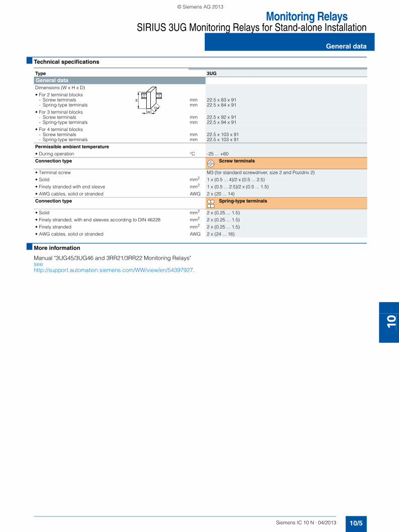
Monitoring RelaysSIRIUS 3UG Monitoring Relays for Stand-alone Installation
10/5Siemens IC 10 N · 04/2013
General data
10
■ Technical specifications
■ More information
Manual "3UG45/3UG46 and 3RR21/3RR22 Monitoring Relays" see http://support.automation.siemens.com/WW/view/en/54397927.
Type 3UG
General dataDimensions (W x H x D)
• For 2 terminal blocks- Screw terminals mm 22.5 x 83 x 91 - Spring-type terminals mm 22.5 x 84 x 91
• For 3 terminal blocks- Screw terminals mm 22.5 x 92 x 91- Spring-type terminals mm 22.5 x 94 x 91
• For 4 terminal blocks- Screw terminals mm 22.5 x 103 x 91- Spring-type terminals mm 22.5 x 103 x 91
Permissible ambient temperature
• During operation °C -25 ... +60
Connection type Screw terminals
• Terminal screw M3 (for standard screwdriver, size 2 and Pozidriv 2)
• Solid mm2 1 x (0.5 ... 4)/2 x (0.5 ... 2.5)
• Finely stranded with end sleeve mm2 1 x (0.5 ... 2.5)/2 x (0.5 ... 1.5)
• AWG cables, solid or stranded AWG 2 x (20 ... 14)
Connection type Spring-type terminals
• Solid mm2 2 x (0.25 ... 1.5)
• Finely stranded, with end sleeves according to DIN 46228 mm2 2 x (0.25 ... 1.5)
• Finely stranded mm2 2 x (0.25 ... 1.5)
• AWG cables, solid or stranded AWG 2 x (24 ... 16)
W
H
D
SIRIUS_IC10N_German_2013-04.book Seite 5 Freitag, 17. Mai 2013 10:32 10
© Siemens AG 2013

Monitoring RelaysSIRIUS 3UG Monitoring Relays for Stand-alone InstallationResidual current monitoring: Residual current monitoring relays
10/6 Siemens IC 10 N · 04/2013
10
■ Overview
SIRIUS 3UG4625 monitoring relays
The 3UG4625 residual current monitoring relays are used in con-junction with the 3UL23 residual current transformers for moni-toring plants in which higher residual currents are increasingly expected due to environmental conditions. Monitoring encompasses pure AC residual currents or AC currents with a pulsating DC residual current component (transformer type A according to DIN VDE 0100-530 and IEC TR 60755).
■ Benefits
• Global use thanks to wide voltage range from 24 to 240 V AC/DC
• High measuring accuracy of ± 7.5 %• Permanent self-monitoring• Variably adjustable threshold values for warning and discon-
nection• Freely configurable delay times and RESET response• Permanent display of the actual value and fault diagnostics via
the display• High level of flexibility and space saving through installation of
the transformer inside or outside the control cabinet• Width 22.5 mm• All versions have removable terminals• All versions with screw or spring-type terminals
■ Application
Monitoring of plants in which residual currents can occur, e.g. due to dust deposits or moisture, porous cables and leads, or capacitive residual currents
■ Technical specifications
3UG4625 monitoring relays
The main conductor and any neutral conductor to which a load is connected, are routed through the opening of the annular strip-wound core of a residual current transformer. A secondary winding is placed around this annular strip-wound core to which the monitoring relay is connected.
If operation of a plant is fault-free, the sum of the inflowing and outward currents equals zero. No current is then induced in the secondary winding of the residual current transformer.
However, if an insulation fault occurs, the sum of the inflowing currents is greater than that of the outward currents. The differ-ential current, i.e. residual current, induces a secondary current in the secondary winding of the transformer. This current is eval-uated in the monitoring relay and is used on the one hand to dis-play the actual residual current and on the other, to switch the relay if the set warning or tripping threshold is overshot.
If the measured residual current exceeds the set warning value, the associated changeover contact instantly changes the switching state and an indication appears on the display.
If the measured residual current exceeds the set tripping value, the set delay time begins and the associated relay symbol flashes. On expiry of this time, the associated changeover con-tact changes the switching state.
ON-delay time for motor start
To be able to start a drive, the output relays switch to the OK state once a residual current is detected for an adjustable ON-delay time, depending on whether the open-circuit or closed-circuit principle is selected.
The changeover contacts do not react if the set threshold value is overshot during this period.
With the closed-circuit principle selected
Residual current monitoring with Auto RESET (memory = no)
If the device is set to Auto RESET, the relay for the tripping value will switch again to the OK state once the value falls below the set hysteresis threshold and the display stops flashing.
The associated relay changes its switching state if the value falls below the fixed hysteresis value of 5 % of the set warning value.
Any overshoots are therefore not stored.
!
> > !
Hysteresis
= 0,02 A
Hysteresis = 5 %
onDelayonDelay
InitDelay
IC01
_002
25
A1-A2
11/14
11/12
21/24
21/22
= 0
SIRIUS_IC10N_German_2013-04.book Seite 6 Freitag, 17. Mai 2013 10:32 10
© Siemens AG 2013

Monitoring RelaysSIRIUS 3UG Monitoring Relays for Stand-alone Installation
10/7Siemens IC 10 N · 04/2013
Residual current monitoring:Residual current monitoring relays
10
With the closed-circuit principle selected
Residual current monitoring with Manual RESET (memory = yes)
If Manual RESET is selected in the menu, the output relays re-main in their current switching state and the current measured value and the symbol for overshooting continues to flash, even when the measured residual current returns to a permissible value. This stored fault status can be reset by pressing the UP▲ or DOWN▼ key simultaneously for > 2 seconds, or by switching the supply voltage off and back on again.
Note:
The neutral conductor must not be grounded downstream of the residual current transformer as this may impair the function of the residual current monitoring device.
Circuit diagram
!
> > !
Hysteresis
= 0,02 A
Hysteresis = 5 %
Delay onDelayonDelayonDelay
Init
t > 2,5 sA1-A2Reset
11/14
11/12
21/24
21/22
= 0
IC01
_002
26
Type 3UG4625-1CW30,3UG4625-2CW30
General dataRated insulation voltage for overvoltage category III according to IEC 60664 for pollution degree 3
V 300
Rated impulse withstand voltage kV 4
Control circuits
Number of CO contacts for auxiliary contacts 2
Thermal current of the contact block with contacts maximum A 5
Current carrying capacity of the output relay
• At AC-15 At 250 V At 50/60 Hz A 3
• At DC-13- At 24 V A 1- At 125 V A 0.2- At 250 V A 0.1
Operational current at 17 V minimum mA 5
Note:It is not necessary to protect the measuring circuit for device protection. The protective device for line protection depends on the cross-section used.
3UG4625
12 14 22 24
2111A1 +
- A2
C2C1
IC01_00224
SIRIUS_IC10N_German_2013-04.book Seite 7 Freitag, 17. Mai 2013 10:32 10
© Siemens AG 2013

Monitoring RelaysSIRIUS 3UG Monitoring Relays for Stand-alone InstallationResidual current monitoring: Residual current monitoring relays
10/8 Siemens IC 10 N · 04/2013* You can order this quantity or a multiple thereof.
Illustrations are approximate
10
■ Selection and ordering data
• For monitoring residual currents from 0.03 to 40 A, from 16 to 400 Hz
• For 3UL23 residual current transformers with feed-through opening from 35 to 210 mm
• Permanent self-monitoring• Certified according to IEC 60947, functionality corresponds to
IEC 62020• Digital adjustable, with illuminated LC display• Permanent display of actual value and tripping state• Separately adjustable limit value and warning threshold• 1 CO contact each for warning threshold and tripping thresh-
old
PU (UNIT, SET, M) = 1 PS* = 1 unit PG = 41H
Accessories see page 10/10.
3UL23 residual current transformer see page 10/9.
Measur-able current
Adjustable current response value
Switching hysteresis
Adjustable response delay time
Rated control supply voltage DT Screw terminals DT Spring-type terminals
At 50 Hz AC
At 60 Hz AC
At DC Order No. Price €per PU
Order No. Price €per PU
A A % s V V V
0.01 ... 43 0.03 ... 40 0 ... 50 0 ... 20 24 ... 240 24 ... 240 24 ... 240 A 3UG4625-1CW30 A 3UG4625-2CW30
3UG4625-1CW30 3UG4625-2CW30
SIRIUS_IC10N_German_2013-04.book Seite 8 Freitag, 17. Mai 2013 10:32 10
© Siemens AG 2013

Monitoring RelaysSIRIUS 3UG Monitoring Relays for Stand-alone Installation
Residual current monitoring:Residual current transformers
10/9Siemens IC 10 N · 04/2013* You can order this quantity or a multiple thereof.Illustrations are approximate
10
■ Overview
SIRIUS 3UL23 residual current transformers
The 3UL23 residual current transformers detect residual cur-rents in machines and plants. They are suitable for pure AC re-sidual currents or AC currents with a pulsating DC residual cur-rent component (transformer type A according to DIN VDE 0100-530 and IEC TR 60755).
Together with the 3UG4625 or 3UG4825 residual current moni-toring relays for IO-Link, they enable residual current monitoring and ground-fault monitoring.
The 3UL2302-1A and 3UL2303-1A residual current transformers with a bushing opening from 35 to 55 mm can be mounted in conjunction with the 3UL2900 accessories on a TH 35 standard mounting rail according to IEC 60715.
■ Technical specifications
Dimensional drawing
■ Selection and ordering data
■ Accessories
Type
b
c a
IC01
_002
29a
de
f
a
355580110140210
d
505050505046
e
646464646462
3UL2302-1A3UL2303-1A3UL2304-1A3UL2305-1A3UL2306-1A3UL2307-1A
6,2
f
-- 386084,5110161
b
7092124,5163201300
c
75,598130169207,5286
Diameter of the bushing opening
Max. rated current per phase
Max. connectable conduc-tor cross-section of the connection terminal
DT Screw terminals PU(UNIT,
SET, M)
PS* PG
mm A mm2Order No. Price €
per PUResidual current transformer (essential accessory for 3UG4625 and 3UG4825)
35 85 2.5 B 3UL2302-1A 1 1 unit 41H
55 150 2.5 B 3UL2303-1A 1 1 unit 41H
80 225 2.5 B 3UL2304-1A 1 1 unit 41H
110 400 2.5 B 3UL2305-1A 1 1 unit 41H
140 500 2.5 B 3UL2306-1A 1 1 unit 41H
210 630 4 B 3UL2307-1A 1 1 unit 41H
Version DT Order No. Price €per PU
PU(UNIT,
SET, M)
PS* PG
Adapters
3UL2900
Adapters
For standard rail mountingFor 3UL23 up to 55 mm diameter
A 3UL2900 1 2 units 41H
© Siemens AG 2013

Monitoring RelaysSIRIUS 3UG Monitoring Relays for Stand-alone Installation
Accessories
10/10 Siemens IC 10 N · 04/2013* You can order this quantity or a multiple thereof.
Illustrations are approximate
10
■ Selection and ordering data
1) PC labeling system for individual inscriptionof unit labeling plates available from:murrplastik Systemtechnik GmbHsee Catalog IC 10, Chapter 16, "Appendix" ➞ "External Partners".
Use Version DT Order No. Price €per PU
PU(UNIT,
SET, M)
PS* PG
Blank inscription labels
3RT1900-1SB20
For 3UG4 Unit labeling plates for SIRIUS devices
20 mm x 7 mm, pastel turquoise1) D 3RT1900-1SB20 100 340 units 41B
For 3UG4 Inscription labels for sticking for SIRIUS devices
19 mm x 6 mm, pastel turquoise C 3RT1900-1SB60 100 3 060units
41B
19 mm x 6 mm zinc yellow C 3RT1900-1SD60 100 3 060units
41B
Push-in lugs and covers
3RP1903
For 3UG4 Push-in lugs For screw fixing, 2 units are required for each device
B 3RP1903 1 10 units 41H
3RP1902
For 3UG4 Sealable covers for securing against unauthorized adjust-ment of setting knobs
B 3RP1902 1 5 units 41H
Tools for opening spring-type terminals
3RA2908-1A
For auxiliary circuit connec-tions
Screwdrivers For all SIRIUS devices with spring-type ter-minals
Spring-type terminals
3.0 mm x 0.5 mm, length approx. 200 mm, titanium gray/black, partially insulated
A 3RA2908-1A 1 1 unit 41B
Manuals For 3UG48 For the manual "3UG45/3UG46,
3RR21/3RR22 Monitoring Relays"
• German C 3ZX1012-0UG40-0AB0 1 1 unit 4N1
• English C 3ZX1012-0UG40-0AC0 1 1 unit 4N1
NS
B0_
0142
9b
SIRIUS_IC10N_German_2013-04.book Seite 10 Freitag, 17. Mai 2013 10:32 10
© Siemens AG 2013

Monitoring RelaysSIRIUS 3UG48 Monitoring Relays for Stand-alone Installation for IO-Link
10/11Siemens IC 10 N · 04/2013
General data
10
■ Overview
SIRIUS 3UG48 monitoring relays
The SIRIUS 3UG4 monitoring relays for electronic and mechan-ical variables monitor all important characteristics that allow conclusions to be drawn about the functionality of a plant. Both sudden disturbances and gradual changes, which may indicate the need for maintenance, are detected.
Thanks to their relay outputs, the monitoring relays permit direct disconnection of the affected system sections and alerting, e.g. by the triggering of a warning light. Thanks to adjustable delay times the 3UG4 monitoring relays can respond very flexibly to brief disturbances such as voltage dips or load changes and can thus avoid unnecessary alarms and disconnections and in-crease system availability.
3UG48 monitoring relays for IO-Link
The SIRIUS 3UG48 monitoring relays for IO-Link also offer many other options based upon the monitoring functions of the tried-and-tested SIRIUS 3UG4 monitoring relays:• Measured value transmission to a controller, incl. resolution
and unit, may be parameterizable as to which value is cycli-cally transmitted
• Transmission of alarm flag to a controller• Full diagnosis capability by inquiry as to the cause of the fault
in the diagnosis data set• Remote parameterization is also possible, in addition to or in-
stead of local parameterization• Rapid parameterization of the same devices by duplication of
the parameterization in the controller• Parameter transmission by upload to a controller by IO-Link
call or by parameter server (if IO-Link master from IO-Link Specification V 1.1 and higher is used)
• Consistent central data storage in the event of parameter change locally or using a controller
• Automatic reparameterizing when devices are exchanged• Blocking of local parameterization via IO-Link possible• Faults are saved in parameterizable and non-volatile fashion
to prevent an automatic start-up after voltage failure and make sure diagnosis data is not lost
• By connecting to the automation level there is the option of pa-rameterizing the monitoring relay at any time using a display unit or displaying the measured values in a control room or lo-cally at the machine/control cabinet.
Even without communication via IO-Link the devices continue to function fully autonomously:• Parameterization can take place locally at the device,
independently of a controller.• In the event of failure or before the controller becomes avail-
able the monitoring relays work as long as the control supply voltage (24 V DC) is present.
• If the monitoring relays are operated without the controller, the 3UG48 monitoring relays have, thanks to the integrated SIO mode, an additional semiconductor output, which switches when the adjustable warning threshold is exceeded.
Thanks to the combination of autonomous monitoring relay func-tion and integrated IO-Link communication, redundant sensors and/or analog signal converters – which previously took over the transmission of measured values to a controller, leading to con-siderable extra cost and wiring outlay – are no longer needed.
Because the output relays are still present, the monitoring relays increase the functional reliability of the system, since the control-ler can only fulfill the control tasks if the current measured values are available, whereas the output relays can also be used for the disconnection of the system if limit values that cannot be reached during operation are exceeded.
The individual 3UG48 monitoring relays for IO-Link offer the fol-lowing functions in different combinations:• Phase sequence• Phase failure, neutral conductor failure• Phase unbalance• Undershooting and/or overshooting of voltage thresholds• Undershooting and/or overshooting of current thresholds• Undershooting and/or overshooting of power factor thresh-
olds• Monitoring of the active current or the apparent current• Monitoring of the residual current• Undershooting and/or overshooting of speed thresholds
Note:
More information about the IO-Link communication system see Catalog IC 10, Chapter 2 "Industrial Communication".
Notes on safety
System networking requires suitable protective measures (e.g. network segmentation for IT security among others) in order to ensure safe plant operation, see www.siemens.com/industri-alsecurity.
More information about the subject of Industrial Security see www.siemens.com/industrialsecurity.
SIRIUS_IC10N_German_2013-04.book Seite 11 Freitag, 17. Mai 2013 10:32 10
© Siemens AG 2013

Monitoring RelaysSIRIUS 3UG48 Monitoring Relays for Stand-alone Installation for IO-Link
General data
10/12 Siemens IC 10 N · 04/2013
10
Use of conventional monitoring relays Monitoring relays for IO-Link
Notes:
Devices required for the communication via IO-Link:• Any controller that supports the IO-Link (e.g. ET200S with
CPU or S7-300 plus ET200S distributed I/O, see Catalog ST 70 "SIMATIC Products for Totally Integrated Automation and Mi-cro Automation")
• IO-Link master (IO-Link master 4SI IO-Link or 4SI SIRIUS inter-face module), which can connect all SIRIUS IO-Link devices to a controller, see Catalog IC 10, Chapter 2, "Industrial Com-munication"
Each monitoring relay requires an IO-Link channel.
Order No. scheme
Note:
The Order No. scheme is presented here merely for information purposes and for better understanding of the logic behind the order numbers.
For your orders, please use the order numbers quoted in the Catalog News in the selection and ordering data.
3
1 2
Feeder
PLC
Motor
Monitoring relay3UG46
Monitoring relay3UG46
Monitoring relay3UG46
Analog signal
converter
Current transfor-
mers
Autonomous operation without PLC
Signaling of limit value violation plus measurement data transmission to PLC
Signaling of limit value violation to PLC
1
23
IC01_00003
2
1
1
PLC
IO-Link master
Monitoring relay 3UG48
Monitoring relay 3UG48
Monitoring relay 3UG48 Feeder
Autonomous operation without PLC
Signaling of limit value violation plus measurement data transmission to PLC
2
Motor
1
IC01_00004
IO-Link
Digit of the Order No. 1st - 3rd
4th 5th 6th 7th 8th 9th 10th 11th 12th
@@@ @ @ @ @ – @ @ @ @ @
Monitoring relays 3 U G
Generation @
Type of setting @
Functions @ @
Connection methods @
Contacts @
Supply voltage @
Signal type of the control supply voltage @
Special version @
Example 3 U G 4 8 2 5 – 1 C A 4 0
SIRIUS_IC10N_German_2013-04.book Seite 12 Freitag, 17. Mai 2013 10:32 10
© Siemens AG 2013

Monitoring RelaysSIRIUS 3UG48 Monitoring Relays for Stand-alone Installation for IO-Link
10/13Siemens IC 10 N · 04/2013
General data
10
■ Benefits
• Simple cyclical transmission of the current measured values, relay switching states and events to a controller
• Remote parameterization• Automatic reparameterizing when devices are exchanged• Simple duplication of identical or similar parameterizations• Reduction of control current wiring • Elimination of testing costs and wiring errors• Reduction of configuration work• Integration in TIA means clear diagnostics if a fault occurs• Cost saving and space saving in control cabinet due to the
elimination of AI and IO modules as well as analog signal con-verters and duplicated sensors
Advantages through energy efficiency
Overview of the energy management process
We offer you a unique portfolio for efficient industrial energy management, using an energy management system that helps to optimally define your energy needs. We split up our industrial energy management into three phases – identify, evaluate, and realize – and we support you with the appropriate hardware and software solutions in every process phase.
The innovative products of the SIRIUS Industrial Controls port-folio can also make a substantial contribution to a plant's energy efficiency (www.siemens.com/sirius/energysaving).
The 3UG48 monitoring relays for IO-Link contribute to energy efficiency throughout the plant as follows:• Shutdown in the event of no-load operation (e.g. pump no-
load operation)• Reactive-power compensation by means of power factor
monitoring• Load shedding of predefined loads in the event of current
overshoots
■ Application
The use of SIRIUS monitoring relays for IO-Link is particularly recommended for machines and plant in which these relays, in addition to their monitoring function, are to be connected to the automation level for the rapid, simple and fault-free provision of the current measured values and/or for remote parameterization.
The monitoring relays can either relieve the controller of monitor-ing tasks or, as a second monitoring entity in parallel to and in-dependent of the controller, increase the reliability in the process or in the system. In addition, the elimination of AI and IO modules allows the width of the controller to be reduced despite signifi-cantly expanded functionality.
EvaluationEner
gy
efficiency consulting
Realization
according toEN 16001
Iden
tifica
tion
IC01_00135
SIRIUS_IC10N_German_2013-04.book Seite 13 Freitag, 17. Mai 2013 10:32 10
© Siemens AG 2013

Monitoring RelaysSIRIUS 3UG48 Monitoring Relays for Stand-alone Installation for IO-Link
General data
10/14 Siemens IC 10 N · 04/2013
10
■ Technical specifications
■ More information
Manual "3UG48/3RR24 Monitoring Relays for IO-Link" see http://support.automation.siemens.com/WW/view/en/54375430.
Notes on safety
System networking requires suitable protective measures (e.g. network segmentation for IT security among others) in order to ensure safe plant operation, see www.siemens.com/industri-alsecurity.
More information about the subject of Industrial Security see www.siemens.com/industrialsecurity.
Type 3UG48
General technical specificationsDimensions (W x H x D)
• For 3 terminal blocks- Screw terminals mm 22.5 x 92 x 91- Spring-type terminals mm 22.5 x 94 x 91
• For 4 terminal blocks- Screw terminals mm 22.5 x 103 x 91- Spring-type terminals mm 22.5 x 103 x 91
Permissible ambient temperature• During operation °C -25 ... +60
Connection type Screw terminals
• Terminal screw M3 (for standard screwdriver, size 2 and Pozidriv 2)• Solid mm2 1 x (0.5 ... 4), 2 x (0.5 ... 2.5)• Finely stranded with end sleeve mm2 1 x (0.5 ... 2.5), 2 x (0.5 ... 1.5)• AWG cables, solid or stranded AWG 2 x (20 ... 14)• Tightening torque Nm 0.8 … 1.2
Connection type Spring-type terminal
• Solid mm2 2 x (0.25 ... 1.5)• Finely stranded, with end sleeves according to DIN 46228 mm2 2 x (0.25 ... 1.5)• Finely stranded mm2 2 x (0.25 ... 1.5)• AWG cables, solid or stranded AWG 2 x (24 ... 16)
W
H
D
SIRIUS_IC10N_German_2013-04.book Seite 14 Freitag, 17. Mai 2013 10:32 10
© Siemens AG 2013

Monitoring RelaysSIRIUS 3UG48 Monitoring Relays for Stand-alone Installation for IO-Link
10/15Siemens IC 10 N · 04/2013
Residual current monitoring:Residual current monitoring relays
10
■ Overview
SIRIUS 3UG4825 monitoring relay
The 3UG4825 residual current monitoring relays are used in con-junction with the 3UL23 residual current transformers for moni-toring plants in which higher residual currents are increasingly expected due to environmental conditions. Monitoring encom-passes pure AC residual currents or AC currents with a pulsating DC residual current component (transformer type A according to DIN VDE 0100-530 and IEC TR 60755).
■ Benefits
• High measuring accuracy of ± 7.5 %• Permanent self-monitoring• Parameterization of devices locally or via IO-Link• Variably adjustable threshold values for warning and discon-
nection• Freely configurable delay times and RESET response• Display and transmission of actual value and status messages
to controller• High level of flexibility and space saving through installation of
the transformer inside or outside the control cabinet• Width 22.5 m• All versions have removable terminals• All versions with screw or spring-type terminals
■ Application
Monitoring of plants in which residual currents can occur, e.g. due to dust deposits or moisture, porous cables and leads, or capacitive residual currents
■ Technical specifications
3UG4825 monitoring relays
The main conductor and any neutral conductor to which a load is connected, are routed through the opening of the annular strip-wound core of a residual current transformer. A secondary winding is placed around this annular strip-wound core to which the monitoring relay is connected.
If operation of a plant is fault-free, the sum of the inflowing and outward currents equals zero. No current is then induced in the secondary winding of the residual current transformer.
However, if an insulation fault occurs, the sum of the inflowing currents is greater than that of the outward currents. The differ-ential current, i.e. residual current, induces a secondary current in the secondary winding of the transformer. This current is eval-uated in the monitoring relay and is used on the one hand to dis-play the actual residual current and on the other, to switch the re-lay if the set warning or tripping threshold is overshot.
If the measured residual current exceeds the set warning value, the associated changeover contact instantly changes the switching state and an indication appears on the display.
If the measured residual current exceeds the set tripping value, the set delay time begins and the associated relay symbol flashes. On expiry of this time, the associated changeover con-tact changes the switching state.
ON-delay time for motor start
To be able to start a drive, the output relays switch to the OK state once a residual current is detected for an adjustable ON-delay time, depending on whether the open-circuit or closed-cir-cuit principle is selected.
The changeover contacts do not react if the set threshold value is overshot during this period.
With the closed-circuit principle selected
Residual current monitoring with Auto RESET (memory = no)
If the device is set to Auto RESET, the relay for the tripping value will switch again to the OK state once the value falls below the set hysteresis threshold and the display stops flashing.
The associated relay changes its switching state if the value falls below the fixed hysteresis value of 5 % of the warning value.
Any overshoots are therefore not stored.
!
> > !
Hysteresis
= 0,02 A
Hysteresis = 5 %
onDelayonDelay
InitDelay
L+/L-
11/14
11/12
Qon 21/24
Qoff 21/22
= 0
IC01
_002
27
SIRIUS_IC10N_German_2013-04.book Seite 15 Freitag, 17. Mai 2013 10:32 10
© Siemens AG 2013

Monitoring RelaysSIRIUS 3UG48 Monitoring Relays for Stand-alone Installation for IO-LinkResidual current monitoring:Residual current monitoring relays
10/16 Siemens IC 10 N · 04/2013
10
With the closed-circuit principle selected
Residual current monitoring with Manual RESET (memory = yes)
If Manual RESET is selected in the menu, the output relays re-main in their current switching state and the current measured value and the symbol for overshooting continues to flash, even when the measured residual current returns to a permissible value. This stored fault status can be reset by pressing the UP▲ or DOWN▼ key simultaneously for > 2 seconds, or by switching the supply voltage off and back on again.
Note:
The neutral conductor must not be grounded downstream of the summation current transformer as this may impair the function of the residual current monitoring device.
Circuit diagram
!
> > !
Hysteresis
= 0,02 A
Hysteresis = 5 %
DelayonDelay
onDelayonDelay
Init
t > 2,5 sL+/L-Reset
11/14
11/12
Qon 21/24
Qoff 21/22
= 0
IC01
_002
28
Type 3UG4825-1CA40, 3UG4825-2CA40
General dataRated insulation voltage for overvoltage category III according to IEC 60664 for pollution degree 3
V 300
Rated impulse withstand voltage kV 4
Control circuits
Number of CO contacts for auxiliary contacts 2
Thermal current of the contact block with contacts maximum A 5
Current carrying capacity of the output relay • At AC-15 At 250 V At 50/60 Hz A 3• At DC-13
- At 24 V A 1- At 125 V A 0.2- At 250 V A 0.1
Operational current at 17 V minimum mA 5
Note:It is not necessary to protect the measuring circuit for device protection. The protective device for line protection depends on the cross-section used.
3UG4825
IC01_00223
12 14 22 24
2111C2C1L-L+ C/Q
IO-Link
SIRIUS_IC10N_German_2013-04.book Seite 16 Freitag, 17. Mai 2013 10:32 10
© Siemens AG 2013
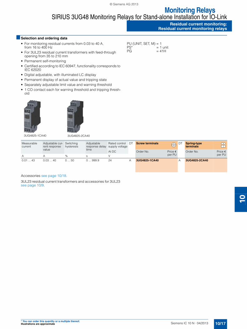
Monitoring RelaysSIRIUS 3UG48 Monitoring Relays for Stand-alone Installation for IO-Link
Residual current monitoring:Residual current monitoring relays
10/17Siemens IC 10 N · 04/2013* You can order this quantity or a multiple thereof.Illustrations are approximate
10
■ Selection and ordering data
• For monitoring residual currents from 0.03 to 40 A, from 16 to 400 Hz
• For 3UL23 residual current transformers with feed-through opening from 35 to 210 mm
• Permanent self-monitoring• Certified according to IEC 60947, functionality corresponds to
IEC 62020• Digital adjustable, with illuminated LC display• Permanent display of actual value and tripping state• Separately adjustable limit value and warning threshold• 1 CO contact each for warning threshold and tripping thresh-
old
PU (UNIT, SET, M) = 1 PS* = 1 unit PG = 41H
Accessories see page 10/18.
3UL23 residual current transformers and accessories for 3UL23 see page 10/9.
Measurable current
Adjustable cur-rent response value
Switching hysteresis
Adjustable response delay time
Rated control supply voltage
DT Screw terminals DT Spring-type terminals
At DC Order No. Price €per PU
Order No. Price €per PUA A % s V
0.01 ... 43 0.03 ... 40 0 ... 50 0 ... 999.9 24 A 3UG4825-1CA40 A 3UG4825-2CA40
3UG4825-1CA40 3UG4825-2CA40
SIRIUS_IC10N_German_2013-04.book Seite 17 Freitag, 17. Mai 2013 10:32 10
© Siemens AG 2013

Monitoring RelaysSIRIUS 3UG48 Monitoring Relays for Stand-alone Installation for IO-Link
Accessories
10/18 Siemens IC 10 N · 04/2013* You can order this quantity or a multiple thereof.
Illustrations are approximate
10
■ Selection and ordering data
1) PC labeling system for individual inscriptionof unit labeling plates available from:murrplastik Systemtechnik GmbHsee Catalog IC 10, Chapter 16, "Appendix" ➞ "External Partners".
Use Version DT Order No. Price €per PU
PU(UNIT,
SET, M)
PS* PG
Blank inscription labels
3RT1900-1SB20
For 3UG48 Unit labeling plates for SIRIUS devices
20 mm x 7 mm, titanium gray1) D 3RT2900-1SB20 100 340 units 41B
For 3UG48 Inscription labels for sticking for SIRIUS devices
19 mm x 6 mm, pastel turquoise C 3RT1900-1SB60 100 3 060units
41B
19 mm x 6 mm zinc yellow C 3RT1900-1SD60 100 3 060units
41B
Push-in lugs and covers
3RP1903
For 3UG48 Push-in lugs For screw fixing,2 units are required for each device
B 3RP1903 1 10 units 41H
3RP1902
For 3UG48 Sealable covers for securing against unauthorized adjust-ment of setting knobs
B 3RP1902 1 5 units 41H
Tools for opening spring-type terminals
3RA2908-1A
For auxiliary cir-cuit connec-tions
Screwdrivers For all SIRIUS devices with spring-type ter-minals
Spring-type terminals
3.0 mm x 0.5 mm, length approx. 200 mm, titanium gray/black, partially insulated
A 3RA2908-1A 1 1 unit 41B
Manuals For 3UG48 Manuals "3UG48/3RR24 Monitoring
Relays for IO-Link"
• German C 3ZX1012-0UG48-0AB1 1 1 unit 4N1• English C 3ZX1012-0UG48-0AC1 1 1 unit 4N1
NS
B0_
0142
9b
SIRIUS_IC10N_German_2013-04.book Seite 18 Freitag, 17. Mai 2013 10:32 10
© Siemens AG 2013
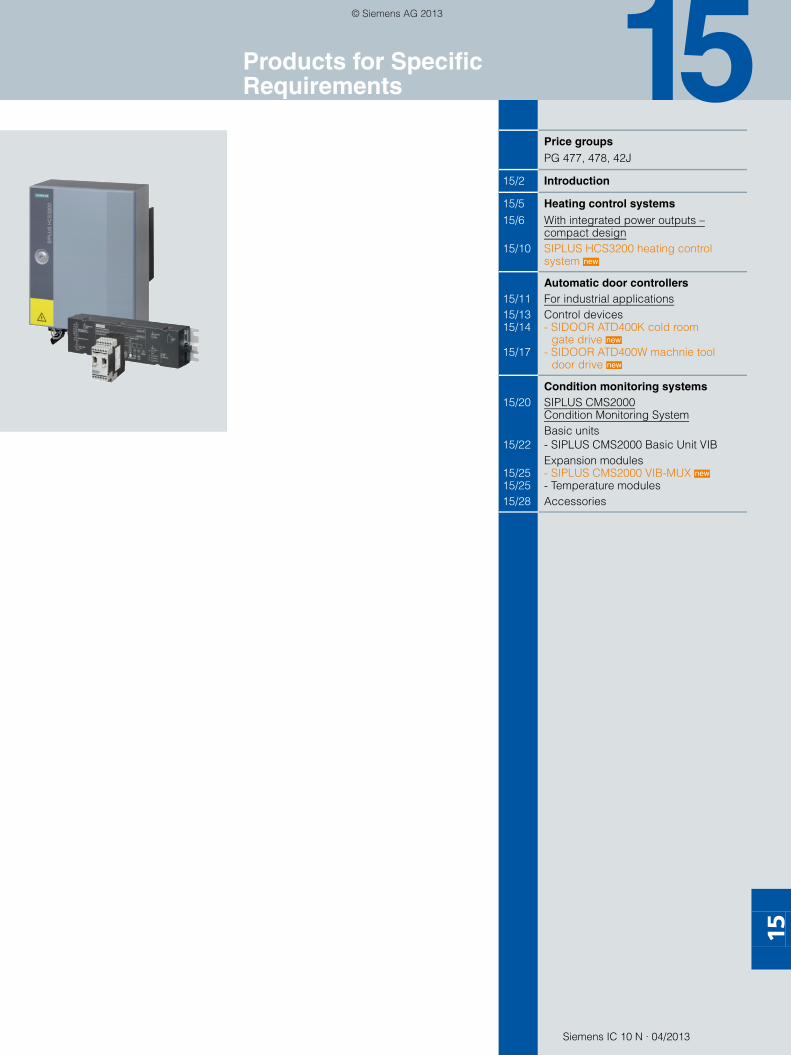
Siemens IC 10 N · 04/2013
15
15
Price groupsPG 477, 478, 42J
15/2 Introduction
15/5 Heating control systems15/6 With integrated power outputs –
compact design15/10 SIPLUS HCS3200 heating control
system
Automatic door controllers15/11 For industrial applications15/13 Control devices15/14 - SIDOOR ATD400K cold room
gate drive 15/17 - SIDOOR ATD400W machnie tool
door drive
Condition monitoring systems15/20 SIPLUS CMS2000
Condition Monitoring SystemBasic units
15/22 - SIPLUS CMS2000 Basic Unit VIBExpansion modules
15/25 - SIPLUS CMS2000 VIB-MUX 15/25 - Temperature modules15/28 Accessories
new
new
new
new
Products for Specific Requirements
SIRIUS_IC10N_German_2013-04.book Seite 1 Freitag, 17. Mai 2013 10:32 10
© Siemens AG 2013

Products for Specific Requirements
Introduction
15/2 Siemens IC 10 N · 04/2013
15
■ Overview
Heating control systems
More information see Industry Mall or www.siemens.com/siplus-hcs.
SIPLUS HCS3200
with integrated power outputs – compact design SIPLUS HCS3200 heating control system
• The central solution for power outputs up to 4 kW
• 9 power outputs 400 V AC
• 1 output for controlling an external fan 230 V AC up to 500 W
• Compact design: 9 power channels on only 0.12 m²
• High degree of protection IP65
• Integrated zero-point switching SIRIUS solid-state switching devices
• Extensive diagnostic functions
• Easy data management with TIA
• Integrated line voltage sensing for compensation of line voltage fluctuations
• Two-phase protection of the outputs with miniature fuses in fuse holders
• Network supply and heat emitter connection via easily accessible connectors on the bottom
• Connection for 24 V DC power supply and PROFIBUS DP via the ECOFAST plugs
• Fast mounting with variable mounting brackets
Pages 15/5 to 15/10
SIRIUS_IC10N_German_2013-04.book Seite 2 Freitag, 17. Mai 2013 10:32 10
© Siemens AG 2013

Products for Specific Requirements
15/3Siemens IC 10 N · 04/2013
Introduction
15
Automatic door controllers
For more information see Industry Mall or www.siemens.com/sidoor.
SIDOOR ATD400K cold room gate drive SIDOOR ATD400W machine tool door drive
Control devices for industrial applicationsSIDOOR ATD400K cold room gate drive
• The SIDOOR ATD400K controller is an intelligent door control system with an integrated relay module for the operation of cold room gates. It is available in a choice of two versions (type Basic for connecting a light barrier, type 1 for connecting a gate interlock).
• 400 kg max. dynamic door weight
• 1-button operation for the entire commissioning process
• The "cord-operated switch" function is supported. When actuated, the gate opens with an adjustable opening width and hold-open time before it closes again automatically.
• A higher force can be set for the first 10 cm of the opening movement (lifting the gate)
• Application-optimized power supply unit
• Communication interfaces: USB via USB adapter, RS 485
• Emergency power module 24 V DC
• Automatic door weight detection – hence stable drive characteristics and reduced service costs
• IP54 motor protection (IP40 for gear unit) as standard for 400 kg motor versions
• SIDOOR user software (included in the software kit) enables user-friendly operation and detailed diagnosis.
Pages 15/14 to 15/16
SIDOOR ATD400W machine tool door drive
• The SIDOOR ATD400W controller is an intelligent door control system for the operation of machine tool doors. One relay module is integrated.
• 400 kg max. dynamic door weight
• 1-button operation for the entire commissioning process
• Performance level "d" according to ISO 13849-1 (limitation of force and energy)
• Category "2" according to ISO 13849-1
• Application-optimized power supply unit
• Communication interfaces: USB via USB adapter, RS 485
• Emergency power module 24 V DC
• Automatic door weight detection – hence stable drive characteristics and reduced service costs
• IP54 motor protection (IP40 for gear unit) as standard for 400 kg motor versions
• SIDOOR user software (included in the software kit) enables user-friendly operation and detailed diagnosis.
Pages 15/17 to 15/19
SIRIUS_IC10N_German_2013-04.book Seite 3 Freitag, 17. Mai 2013 10:32 10
© Siemens AG 2013
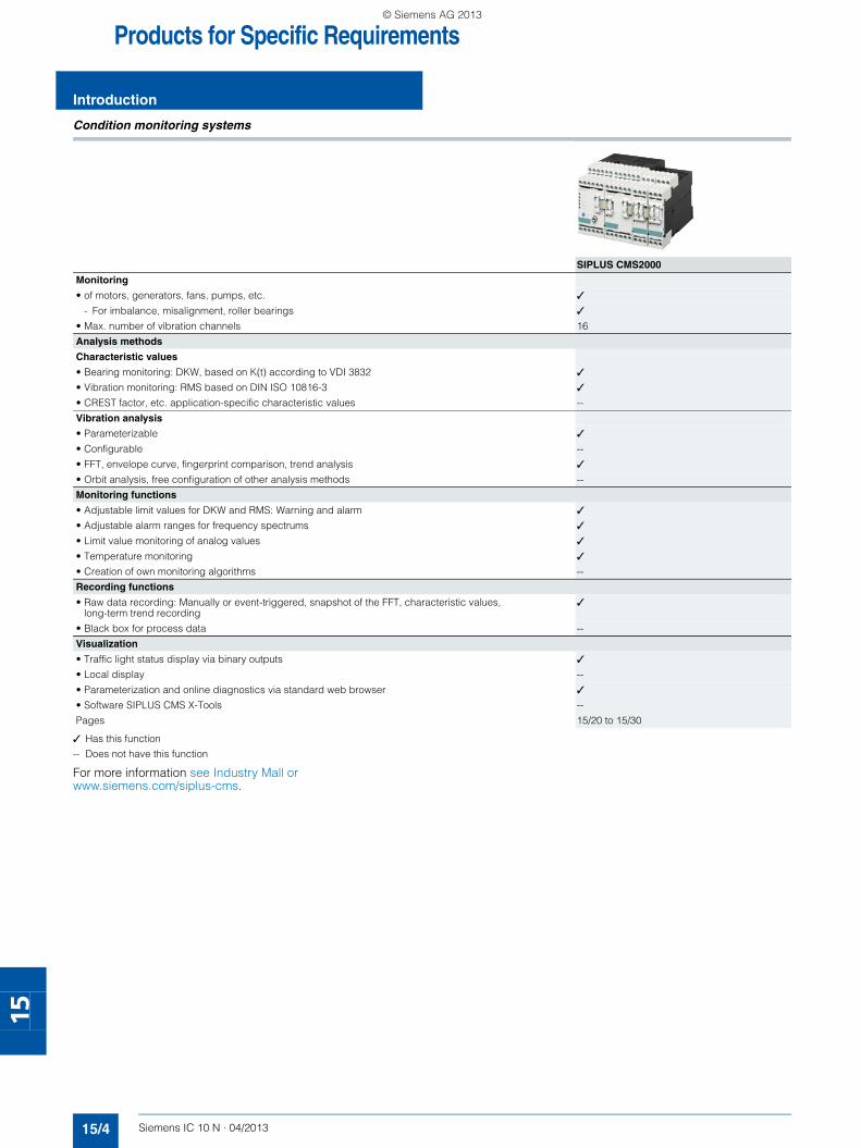
Products for Specific Requirements
Introduction
15/4 Siemens IC 10 N · 04/2013
15
Condition monitoring systems
✓ Has this function
-- Does not have this function
For more information see Industry Mall or www.siemens.com/siplus-cms.
SIPLUS CMS2000
Monitoring
• of motors, generators, fans, pumps, etc. ✓
- For imbalance, misalignment, roller bearings ✓
• Max. number of vibration channels 16
Analysis methods
Characteristic values
• Bearing monitoring: DKW, based on K(t) according to VDI 3832 ✓
• Vibration monitoring: RMS based on DIN ISO 10816-3 ✓
• CREST factor, etc. application-specific characteristic values --
Vibration analysis
• Parameterizable ✓
• Configurable --
• FFT, envelope curve, fingerprint comparison, trend analysis ✓
• Orbit analysis, free configuration of other analysis methods --
Monitoring functions
• Adjustable limit values for DKW and RMS: Warning and alarm ✓
• Adjustable alarm ranges for frequency spectrums ✓
• Limit value monitoring of analog values ✓
• Temperature monitoring ✓
• Creation of own monitoring algorithms --
Recording functions
• Raw data recording: Manually or event-triggered, snapshot of the FFT, characteristic values, long-term trend recording
✓
• Black box for process data --
Visualization
• Traffic light status display via binary outputs ✓
• Local display --
• Parameterization and online diagnostics via standard web browser ✓
• Software SIPLUS CMS X-Tools --
Pages 15/20 to 15/30
SIRIUS_IC10N_German_2013-04.book Seite 4 Freitag, 17. Mai 2013 10:32 10
© Siemens AG 2013

Heating Control Systems
15/5Siemens IC 10 N · 04/2013
General data
15
■ Overview
Heating control systems
In manufacturing processes where temperature plays a crucial role, deviations of just a few degrees can cause enormous qual-ity problems. To avoid this and to minimize rejection rates, high-precision and reliable, individual control of the electrical heating elements is essential.
Nearly all industrially manufactured products undergo heat treatment. Even slight deviations in the heating process can lead to a huge impairment of product quality.
To increase the quality and quantity of a heat-treated product it is important to be able to focus the energy required with the highest level of precision in terms of both time and space. SIPLUS HCS ensures utmost precision in the control of resistive loads such as infrared heaters.
Three heating control systems are available:• With integrated power outputs – compact design• With integrated power outputs – modular design• Without integrated power outputs
The SIPLUS HCS family of heating control systems saves time, costs and resources when it comes to configuring, commission-ing, operation and maintenance.
This is achieved by:• Simple integration into existing automation systems such as
SIMATIC and SIMOTION• Lower wiring overhead and user-friendly engineering• Intelligent diagnostics options for swift fault detection• Service-friendly design thanks to ready-to-use function and
data blocks• Reduced volume in the control cabinet with spacing savings
of up to 50 %
More information see www.siemens.com/siplus-hcs.
■ Benefits
Minimized overhead for commissioning and service• Low wiring expenditure and service-friendly design of system
components• Simple configuration by means of efficient engineering soft-
ware• Intelligent diagnostics options for swift fault detection
High security for investment as part of service-proven auto-mation concepts• Part of Totally Integrated Automation• Integrated PROFIBUS interface for easy integration into exist-
ing automation systems such as SIMATIC and SIMOTION• Worldwide support and service with comprehensive test
equipment
■ Application
The SIPLUS HCS heating control systems are designed for use in the SIMATIC industrial automation system and the SIMOTION motion control system.
They are used above all in the following industries and plants:• Plastics industry: thermoforming, blow molding, injection
molding and extrusion• Automotive industry: drying tunnels in paintshops• Food and beverage industry, e.g. packing lines and PET blow
molding plants
SIRIUS_IC10N_German_2013-04.book Seite 5 Freitag, 17. Mai 2013 10:32 10
© Siemens AG 2013

Heating Control SystemsWith Integrated Power Outputs — Compact Design
General data
15/6 Siemens IC 10 N · 04/2013
15
■ Overview
The distributed solution for use in proximity to heating elements – ideally suited for the linear arrangement of heat emitter arrays,
e.g. for controlling heat emitter arrays to heat preforms in PET blow molding machines.
■ Overview
SIPLUS HCS3200 heating control system with fixing brackets
The SIPLUS HCS3200 heating control system was developed as a compact solution for controlling linear heat emitter arrays.
Thanks to the high IP65 degree of protection, it can be used in-dependently of a control cabinet in a distributed location near the emitters.
■ Benefits
• Reduced wiring outlay through distributed connection• Integrated power output and phase fusing (no additional (out-
put) fuses needed)• Simple mounting and connection• Straightforward maintenance and servicing through easy re-
placement of fuses• Quick commissioning using sample function blocks for SI-
MATIC S7• Various types of heating elements can be operated (e.g.
quartz, halogen and infrared heat emitters) up to 15 times the starting current.
• Insensitive to external influences thanks to a rugged metal en-closure with IP65 degree of protection
• High level of plant availability thanks to fast and precise diag-nostics functions
• Excellent product quality through integrated line voltage com-pensation
• Reduced wiring and up to 50 % space saving compared to conventional solutions
• Automation from a single source: easy data management with TIA
■ Application
• Heating solutions which require distributed connection of the heating control system with a high degree of protection, e.g.- PET blow-molding machines - Roasting/baking/melting/drying of foodstuffs
• Applications with a small number of heater elements, e.g.- Vulcanizing machines- Spot repair emitters- Drying of coatings on headlights
• Applications requiring medium outputs, e.g.- Welding of tanks- Drying of paint, e.g. on gas tanks- Drying of coatings on alloy wheel rims- Forming of loudspeaker covers- Drying of screen prints on panels
■ Design
The main components of the SIPLUS HCS3200 heating control system are:• HCS3200 device built into a metal enclosure with IP65 degree
of protection• Four mounting brackets for attaching the device (included in
scope of supply)
SIPLUS HCS3200 heating control system
SIRIUS_IC10N_German_2013-04.book Seite 6 Freitag, 17. Mai 2013 10:32 10
© Siemens AG 2013

Heating Control SystemsWith Integrated Power Outputs — Compact Design
15/7Siemens IC 10 N · 04/2013
SIPLUS HCS3200 heating control system
15
■ Function
Communications• Via PROFIBUS DP with 12 MBit/s• For importing the parameter settings from the higher-level
controller• For transferring the diagnostic information to the higher-level
controller• Communication takes place via the ECOFAST X3/X4 plugs
and can be looped through from device to device using daisy chaining.
Performance features• Calculation of output control variables of power output chan-
nels• Setpoint values can be adjusted in 1 % increments from 0 %
to 100 %• Zero cross-switching solid-state relays (SSR)• External fan output for connecting a 230 V AC fan up to 500 W
Diagnostics
The following faults are detected:• Defective heating element• Breakdown of solid-state relay (SSR)• Incoming fuse has tripped• Outgoing fuse has tripped or solid state relay (SSR) has high
impedance• Monitoring of the fan output
Air extraction• An internal fan is used in order to obtain uniform heat distribu-
tion within the enclosure. The fan is controlled according to the internal temperature and is also monitored. If the fan is not functioning correctly, a fault is signaled to the user.
• The internal fan is available as an accessory and can be re-placed if it becomes defective.
Power supply to the main circuit• The power supply is two-phase with a voltage of 400 V AC
(± 10 %).• The mains frequency is 50/60 Hz (± 5 %).
Power supply to the internal electronics• The internal electronics of the device must be supplied with 24
V DC ± 20 % (PELV = Protective Extra Low Voltage).• The maximum current consumed per device is 0.25 A.• Connection for 24 V DC power supply and PROFIBUS DP via
the ECOFAST X3/X4 plugs• The 24 V DC supply can be looped through from device to de-
vice using daisy chaining.
Power outputs• Nine power outputs are available for each device• Max. 4 000 W switching capacity per output• Max. 25 200 W switching capacity per device
Fan output
An external 230 V AC fan with a maximum output of 500 W can be operated.
Temperature monitoring
The SIPLUS HCS3200 heating control system is fitted with a sen-sor for monitoring the internal temperature. If a temperature threshold that is permanently set in the hardware is overshot, all the outputs (power outputs and the external fan) are automati-cally switched off to prevent damage to the device.
Fuses• Two gG 16 A fuses per power output for protecting the power
outputs• One gG 4 A fuse for protecting the fan output• All fuses are fitted in fuse holders and are easily accessible.
■ Integration
The SIPLUS HCS3200 heating control system is a distributed I/O device. It communicates via the PROFIBUS DP fieldbus with the SIMATIC S7 controller.
A complete system includes the following components:• SIPLUS HCS3200 heating control system• Higher-level control through SIMATIC S7 automation system
with integrated interface for PROFIBUS DP or SIMOTION• PROFIBUS DP• Cabling• Heat emitter array• HMI panel (optional)
Application example with SIMATIC and SIPLUS HCS3200
Heaterfield
SIMATICS7-1200
SIPLUSHCS3200
SIMATIC HMI TP1200 Comfort
• • •
• • •
PROFIBUS DP
PROFINET
SP01_00027
SIRIUS_IC10N_German_2013-04.book Seite 7 Freitag, 17. Mai 2013 10:32 10
© Siemens AG 2013

Heating Control SystemsWith Integrated Power Outputs — Compact Design
SIPLUS HCS3200 heating control system
15/8 Siemens IC 10 N · 04/2013
15
■ Technical specifications Type 6BK1932-0BA00-0AA0
Product brand name SIPLUS
Product designation HCS3200 Fan, IP65, 9 output channels, fan output
General data
Type of control of heat emitters Half-wave control
Type of load Resistive load
Certificate of suitability CE
Pollution degree 2
Electrical specifications
Main circuit
Power carrying capacity maximum permissible W 25 200
Switching capacity current per phase maximum A 63
Type of voltage of the supply voltage AC
Supply voltage at AC rated value V 400
Supply voltage frequency
• 1 Hz 50• 2 Hz 60
Relative symmetrical tolerance
• of supply voltage % 10• of supply voltage frequency % 5
Type of electrical separation Optocoupler between main circuit and PELV
Power electronics
Number of outputs for heating power 9
Number of heat emitters per output maximum 1
Output voltage at the output for heating power V 400
Relative symmetrical tolerance of the output voltage % 10
Output current at the output for heating power rated value
A 10
Power carrying capacity for heating power
• At 40 °C per output W 4 000• At 50 °C per output W 4 000• Per output minimum W 200
Type of short-circuit protection for heating power per output
Fuse, operating class gG 16 A
Electrical separation between the outputs No
Motor control functions
Number of outputs for fan 1
Output voltage at the output for fan V 230
Power carrying capacity for fan
• Per output W 60 … 500
Type of short-circuit protection at the output for fan Fuse, operating class gG 4 A
Communications
Protocol is supported PROFIBUS DP protocol Yes
Transmission rate for PROFIBUS DP maximum Mbit/s 12
Display
Number of status indicators 2
Type of indicator as status indicator using LEDs LED green = status indicator, LED red = fault indicator
Supply voltage
Type of voltage DC
Supply voltage for electronics V 24
Relative symmetrical tolerance of the input voltage % 20
Bridging time at 24 V for DC in event of power failure ms 20
Recovery time after power failure typical s 1
Consumed current for electronics maximum A 0.25
SIRIUS_IC10N_German_2013-04.book Seite 8 Freitag, 17. Mai 2013 10:32 10
© Siemens AG 2013

Heating Control SystemsWith Integrated Power Outputs — Compact Design
15/9Siemens IC 10 N · 04/2013
SIPLUS HCS3200 heating control system
15
Electrical connections
Type of electrical connection at input for main circuit Plug, 5-pole
Type of connectable conductor cross-sections of main circuit at input
• Finely stranded with end sleeve 3 x (6 ... 25 mm²), 1 x PE (6 ... 16 mm²)• with AWG cables 3 x (8 ... 4), 1 x PE (10 ... 6)
Type of electrical connection at output for heater and fan Plug, 20-pole
Type of connectable conductor cross-sections
• For heater and fan finely stranded with end sleeve 20 x (1.5 ... 4 mm²), 1 x PE (1.5 ... 16 mm²)• with AWG cables stranded 20 x (18 ... 12), 1 x PE (16 ... 6)
Type of electrical connection of the PROFIBUS interface ECOFAST
Monitoring functions
Type of temperature monitoring NTC thermistors
Ambient conditions
Mechanical features
Mounting position Vertical
Type of mounting Screw fixing
Type of ventilation Self-ventilation
Shock resistance according to IEC 60068-2-27 15 g / 11 ms / 3 shocks / axis
Vibration resistance according to IEC 60068-2-6
• During operation 10 ... 58 Hz / 0.15 mm, 58 ... 150 Hz / 1 g• During storage 5 ... 9 Hz / 3.5 mm, 9 ... 500 Hz / 1 g
IP degree of protection IP65
Dimensions
Depth mm 200
Height mm 380
Width mm 300
Electromagnetic compatibility
Conducted interference BURST according to IEC 61000-4-4
2 kV voltage supply cables / 1 kV signal cables
Conducted interference SURGE according to IEC 61000-4-5
On supply cables: 1 kV symmetrical, 2 kV asymmetrical, (24 V DC supply only with external protective measure)on PROFIBUS cable: asymmetrical 1 kV
Conducted interference - phase-to-phase SURGE according to IEC 61000-4-5
kV 1
Conducted interference - phase-to-ground SURGE according to IEC 61000-4-5
kV 2
Conducted interference as radio frequency radiation according to IEC 61000-4-6
10 V (0.15 ... 80 MHz)
Electrostatic discharge according to IEC61000-4-2
4 kV contact discharge / 8 kV air discharge
Field-related interference according to IEC 61000-4-3
10 V/m (80 ... 1 000 MHz), 3 V/m (1.4 ... 2.0 GHz), 1 V/m (2.0 ... 2.7 GHz)
EMC emitted interference Limit value class A according to IEC 61000-6-4:2007 + A1:2011 Group 1
Overvoltage category Installation category III
Climatic ambient conditions
Ambient temperature
• During operation °C 0 … 50• During storage °C -40 … +70• During transport °C -40 … +70
Air pressure
• During operation hPa 860 … 1 080• During storage hPa 660 … 1 080
Relative air humidity
• At 25 °C during operation maximum % 95• At 50 °C during operation maximum % 50
- Note Linearly decreasing to 50 %
Installation altitude at height above sea level maximum m 2 000
Type 6BK1932-0BA00-0AA0
SIRIUS_IC10N_German_2013-04.book Seite 9 Freitag, 17. Mai 2013 10:32 10
© Siemens AG 2013
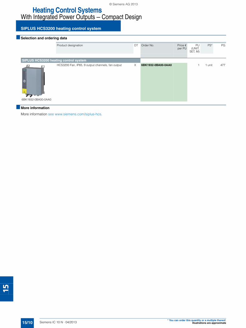
Heating Control SystemsWith Integrated Power Outputs — Compact Design
SIPLUS HCS3200 heating control system
15/10 Siemens IC 10 N · 04/2013* You can order this quantity or a multiple thereof.
Illustrations are approximate
15
■ Selection and ordering data
■ More information
More information see www.siemens.com/siplus-hcs.
Product designation DT Order No. Price €
per PUPU
(UNIT,SET, M)
PS* PG
SIPLUS HCS3200 heating control system
6BK1932-0BA00-0AA0
HCS3200 Fan, IP65, 9 output channels, fan output X 6BK1932-0BA00-0AA0 1 1 unit 477
SIRIUS_IC10N_German_2013-04.book Seite 10 Freitag, 17. Mai 2013 10:32 10
© Siemens AG 2013

Automatic Door Controllers
15/11Siemens IC 10 N · 04/2013
General data
15
■ Overview
Automatic door controllers
■ Design
SIDOOR automatic door control systems
Door control system is the general term for a controller of access systems.
The SIDOOR product family is primarily intended for the opera-tion of sliding doors, whereby these doors can be operated both horizontally and vertically.
Door control systems are characterized by the fact that there are always two defined states for the open and closed position of the door.
The door is always controlled between these positions in accor-dance with the guidelines of the respective application.
In a defined learn run via "1-button operation", the door system independently determines the values for the door width, the dy-namic door weight and the drive direction of the geared motor and stores these data in a non-volatile memory.
The optimum travel behavior at the door is automatically calcu-lated and consistently adhered to.
The travel curve transitions are rounded off so that the door movement is smooth and jerk-free.
for Elevators• Passenger elevators• Freight elevators• Rising doors and rolling shutters
for Industrial Applications• Cold room doors / gates• Protective machine doors / gates• Machine tool doors
for Rail Applications• Interior railway doors• Platform screen doors
SP01_0001
1a
SIRIUS_IC10N_German_2013-04.book Seite 11 Freitag, 17. Mai 2013 10:32 10
© Siemens AG 2013
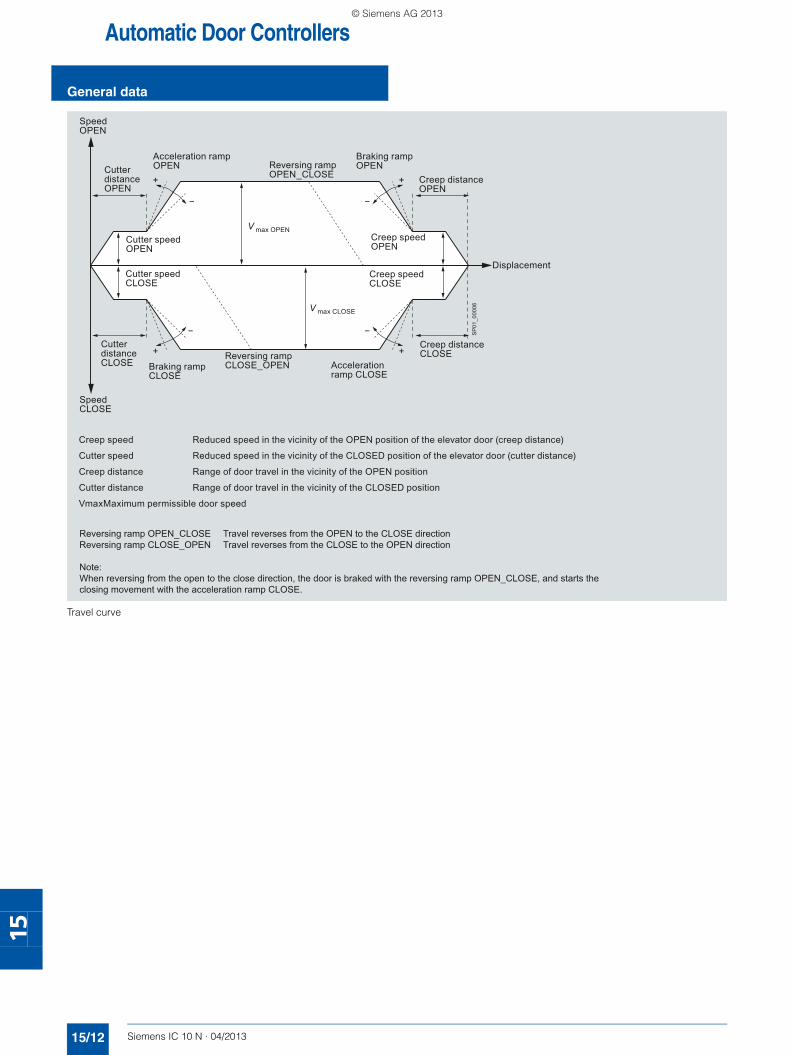
Automatic Door Controllers
General data
15/12 Siemens IC 10 N · 04/2013
15
Travel curve
SpeedOPEN
Reversing ramp OPEN_CLOSE
Acceleration ramp OPEN
Braking rampOPEN
Creep distanceOPEN
Displacement
Cutter distanceOPEN
Cutter distanceCLOSE Braking ramp
CLOSE
SpeedCLOSE
Reversing rampCLOSE_OPEN Acceleration
ramp CLOSE
Creep distance CLOSE
Creep speedCLOSE
Creep speedOPEN
V max OPEN
V max CLOSE
Cutter speedOPEN
Cutter speedCLOSE
Creep speed Reduced speed in the vicinity of the OPEN position of the elevator door (creep distance)
Cutter speed Reduced speed in the vicinity of the CLOSED position of the elevator door (cutter distance)
Creep distance Range of door travel in the vicinity of the OPEN position
Cutter distance Range of door travel in the vicinity of the CLOSED position
VmaxMaximum permissible door speed
Reversing ramp OPEN_CLOSE Travel reverses from the OPEN to the CLOSE directionReversing ramp CLOSE_OPEN Travel reverses from the CLOSE to the OPEN direction
Note:When reversing from the open to the close direction, the door is braked with the reversing ramp OPEN_CLOSE, and starts the closing movement with the acceleration ramp CLOSE.
SP
01_0
0006
SIRIUS_IC10N_German_2013-04.book Seite 12 Freitag, 17. Mai 2013 10:32 10
© Siemens AG 2013

Automatic Door ControllersFor Industrial Applications
15/13Siemens IC 10 N · 04/2013
General data
15
■ Overview
Automatic door controllers for industrial applications
The product-specific application/requirement lies in complying with the special industrial requirements regarding functional safety and the door closing mechanisms. Protective machine doors and power-actuated doors and gates comply with the safety standard ISO 13849-1 (Safety of Machinery and Machin-ery Directive).
■ Overview
SIDOOR control devices are electronic controllers that are con-nected to the power supply via an external power supply unit and can operate one or more application-specific motors.
They are generally connected to the higher-level application via digital or serial interfaces and can be configured via a user inter-face.
for Industrial Applications• Cold room doors / gates• Protective machine doors / gates• Machine tool doors
SP01_0001
3
Control devices
SIRIUS_IC10N_German_2013-04.book Seite 13 Freitag, 17. Mai 2013 10:32 10
© Siemens AG 2013

Automatic Door ControllersFor Industrial ApplicationsControl devices:SIDOOR ATD400K cold room gate drive
15/14 Siemens IC 10 N · 04/2013
15
■ Overview
SIDOOR ATD400K cold room gate drive
The SIDOOR ATD400K cold room gate drive enables the quick, easy and flexible movement, installation and configuration of a wide range of cold room gate systems.
Two different drive versions are available, in which digital input 1 is assigned a different functionality.• Relay module version
- Type Basic for connecting a light barrier- Type 1 for connecting a gate interlock
• For dynamic door weights up to 400 kg• Automatic door weight detection• Operating temperature -20 to +50 °C• Flexible motor management (two different motor types), auto-
matic detection• Opening width 0.3 to 4 m
• Emergency power input via special emergency power module 24 V DC ± 15 %
• Auxiliary power output 24 V DC ± 15 %; 0.4 A (short-circuit-proof)
• Output stage short-circuit-proof • Vandal-proof• IP54 for 180 to 400 kg motor versions,
gear unit IP40• The "cord-operated switch" function is supported. Pulling the
cord opens the door to an adjustable opening width.• Pulse mode: The function remains active until a new command
arrives.• Hold-open time can be parameterized• A higher force can be set for the first 10 cm of the opening
movement (lifting the gate)
■ Benefits
• One-button operation for the entire commissioning process• Optimum and stable drive characteristics• Reduced service requirements and costs• SIDOOR user software (part of the software kit, not included in
the scope of supply, see Catalog IC 10 ⋅ 2013, chapter 15, "Automatic Door Controllers" → "for Elevators" → "Additional Units") enables user-friendly operation and detailed diagnos-tics.
• Integrated terminal module enables simple setup and diag-nostics via an event and statistics memory
• Small footprint thanks to compact design• Automated functions for enhanced safety
5
9
8
34
2
76
1
6 Input signal connection
7
8
9
Control panel
Mains transformer connection
Motor connection
1
2
3
4
5
Emergency power module connection
Relay module connection
Terminal module
Output voltage 24 V DC/400 mA connection
Service Tool- or Software Kit - connection
SP01_00012
SIRIUS_IC10N_German_2013-04.book Seite 14 Freitag, 17. Mai 2013 10:32 10
© Siemens AG 2013

Automatic Door ControllersFor Industrial Applications
15/15Siemens IC 10 N · 04/2013
Control devices:SIDOOR ATD400K cold room gate drive
15
■ Application
The SIDOOR ATD400K cold room gate drive is an intelligent door control system which enables cold room gates to be opened and closed at adjustable speeds and accelerations.
The maintenance-free, variable speed drive unit comprises a DC motor with non-self-locking gearing.
Two different motors are available:• SIDOOR M3 geared motor (30 V DC/4.0 A;
motor for max. overall door leaf weight of 180 kg)• SIDOOR M4 geared motor (30 V DC/4.0 A;
motor for max. overall door leaf weight of 400 kg)
They must be ordered separately, see Catalog IC 10 ⋅ 2013, chapter 15, "Automatic Door Controllers" → "for Elevators" → "Geared Motors".
Operation of the door drive does not require a limit switch. The door width and the "OPEN/CLOSED" positions are determined automatically.
A 7-segment display directly in the SIDOOR ATD400K cold room gate drive indicates the current operating states. Indication is also possible with the service tool or the software kit, see Catalog IC 10 ⋅ 2013, chapter 15, "Automatic Door Controllers" → "for Elevators" → "Additional Units".
Power transmission is via a toothed belt, which passes over a deflector unit and can be fitted with two door clutch holders. The accessory parts are not included in the scope of supply, see Catalog IC 10 ⋅ 2013, chapter 15, "Automatic Door Controllers" → "for Elevators" → "Accessories".
This enables it to drive both single-sided and centrally opening doors.
■ Design
The SIDOOR ATD400K cold room gate drive system is made up of several components.• The SIDOOR AT400K control device (incl. terminal module
and relay module) is available in two versions:- Type Basic supports the light barrier function- Type 1 supports the gate interlock function
The following must be ordered separately:• Mains transformer 6FB1112-0AT20-2TR0, see Catalog IC 10 ⋅
2013, chapter 15, "Automatic Door Controllers" → "for Eleva-tors" → "Power Supply Units"
• Additional units for enabling the universal use and mainte-nance of the door drive system, see Catalog IC 10 ⋅ 2013, chapter 15, "Automatic Door Controllers" → "for Elevators" → "Additional Units".- Software kit 6FB1105-0AT01-6SW0- Service tool 6FB1105-0AT01-6ST0- Emergency power module 6FB1115-0AT10-4CP0
• DC geared motors, see Catalog IC 10 ⋅ 2013, chapter 15, "Au-tomatic Door Controllers" → "for Elevators" → "Geared Motors"- SIDOOR M3 6FB1103-0AT1. -4MB0
(max. door weight 180 kg) or- SIDOOR M4 6FB1103-0AT1. -5MA0
(max. door weight 400 kg)
• Accessories for the overall system, see Catalog IC 10 ⋅ 2013, chapter 15, "Automatic Door Controllers" → "for Elevators" → "Accessories"- Rubber-metal anti-vibration mounts for low-noise operation
of the door drive system:6FB1104-0AT02-0AD0 for geared motor SIDOOR M36FB1104-0AT01-0AD0 for geared motor SIDOOR M4
- Mounting bracket:6FB1104-0AT01-0AS0 for geared motors SIDOOR M3 and SIDOOR M4 for flexible accommodation of the rubber-bonded metal,6FB1104-0AT02-0AS0 for the deflector unit: This enables the toothed belt to be set to the required belt tension.
- Door clutch holder 6FB1104-0AT01-0CP0: This connects the respective door leaf with the toothed belt.
- Deflector unit 6FB1104-0AT03-0AS0 for the toothed belt STS for attaching the door system
- Toothed belt STS as connection between the door system and the end positions of the door:6FB1104-0AT01-0AB0 (length 4 m) and 6FB1104-0AT02-0AB0 (length 45 m)
■ Configuration
During initial commissioning, please note the following:• Mechanical installation and configuration see manual "SI-
DOOR Automatic Door Controllers AT40, ATD400K, ATD400S, ATD400V, ATD400W", http://support.automation.siemens.com/WW/view/en/58531074
• Electrical configuration and commissioning:- Push the door into the "CLOSED" position.- Open the device cover.- Plug in the motor connector- Press and hold the learn run button- The learn run starts automatically and the learn run button
can be released.- On completion of the learn run, the door is in the "CLOSED"
position and the 7-segment display indicates "u".- The door can now be moved via the "OPEN" and "CLOSED"
buttons with the default profile.
■ Programming
• The software kit is available as an additional unit (see Catalog IC 10 ⋅ 2013, chapter 15, "Automatic Door Controllers" → "for Elevators" → "Additional Units"), and allows quick and easy updating of the firmware using the Siemens HCS12 Firmware Loader.
User-friendly parameter setting and oscilloscope function is car-ried out via the SIDOOR user software (part of the software kit).
SIRIUS_IC10N_German_2013-04.book Seite 15 Freitag, 17. Mai 2013 10:32 10
© Siemens AG 2013

Automatic Door ControllersFor Industrial ApplicationsControl devices:SIDOOR ATD400K cold room gate drive
15/16 Siemens IC 10 N · 04/2013* You can order this quantity or a multiple thereof.
Illustrations are approximate
15
■ Technical specifications
■ Selection and ordering data
■ More information
Further product details, see • Manual "SIDOOR Automatic Door Controllers AT40, ATD400K,
ATD400S, ATD400V, ATD400W", http://support.automation.siemens.com/WW/view/en/58531074
• Installation instructions "SIDOOR Software Kit", http://support.automation.siemens.com/WW/view/en/58572351
Power supply units, additional units, geared motors and acces-sories for the SIDOOR ATD400K cold room gate drive see Cata-log IC 10 ⋅ 2013, chapter 15, "Automatic Door Controllers" → "for Elevators".
Type 6FB1111-1AT20-1AT1 6FB1141-1AT11-3KU2
General dataSupply voltage at DC V 36 36
Relative positive tolerance of the supply voltage % 3 3
Input voltage
• per DC input V 10 … 28 10 … 28
Input current
• per DC input mA 9 … 27 9 … 27
Product feature
• Control inputs isolated Yes Yes• Control inputs p-switching Yes Yes
Output current at 24 V DC output maximum mA 400 400
Property of the 24 V DC output
• Note CAUTION: Do not supply with exter-nal voltage!
CAUTION: Do not supply with exter-nal voltage!
• Short-circuit-proof Yes Yes
Product expansion optional Emergency power module Emergency power module
Switching capacity current of the output relay
• At 230 V - At AC mA 10 … 1 000 10 … 1 000
• At 50 V - At DC mA 10 … 1 000 10 … 1 000
Opening width of door m 0.3 … 4 0.3 … 4
Ambient temperature
• During operation °C -20 … +50 -20 … +50• During storage °C -40 … +50 -40 … +50
IP degree of protection IP20 IP20
Relative air humidity
• No condensation % 10 … 93 10 … 93
Dimensions
• Width mm 320 320• Height mm 60 60• Depth mm 80 80
StandardsType of inspection TÜV prototype tested Yes Yes
Standard for EMC IEC 61000-6-2/IEC 61000-6-3 IEC 61000-6-2/IEC 61000-6-3
Certificate of suitability CE marking Yes Yes
Standard for safety IEC 60335-1:2010 IEC 60335-1:2010
Performance level (PL) according to ISO 13849-1 d d
Category according to ISO 13849-1 2 2
Product designation DT Order No. Price €
per PUPU
(UNIT,SET, M)
PS* PG
SIDOOR ATD400K cold room gate drives
6FB1141-1AT1.-3KU2
SIDOOR ATD400K control device for cold room gate
• Type Basic with relay module C 6FB1141-1AT10-3KU2 1 1 unit 478
• Type 1 with relay module C 6FB1141-1AT11-3KU2 1 1 unit 478
SIRIUS_IC10N_German_2013-04.book Seite 16 Freitag, 17. Mai 2013 10:32 10
© Siemens AG 2013
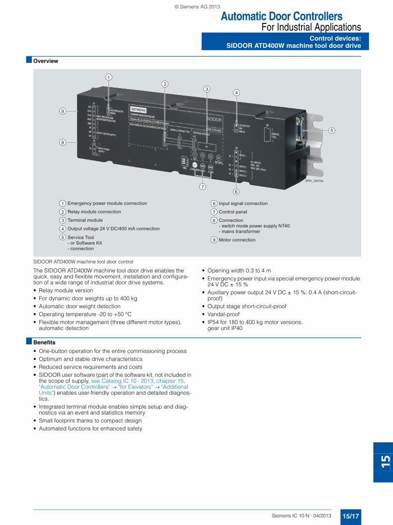
Automatic Door ControllersFor Industrial Applications
15/17Siemens IC 10 N · 04/2013
Control devices:SIDOOR ATD400W machine tool door drive
15
■ Overview
SIDOOR ATD400W machine tool door control
The SIDOOR ATD400W machine tool door drive enables the quick, easy and flexible movement, installation and configura-tion of a wide range of industrial door drive systems.• Relay module version• For dynamic door weights up to 400 kg• Automatic door weight detection• Operating temperature -20 to +50 °C• Flexible motor management (three different motor types),
automatic detection
• Opening width 0.3 to 4 m• Emergency power input via special emergency power module
24 V DC ± 15 %• Auxiliary power output 24 V DC ± 15 %; 0.4 A (short-circuit-
proof)• Output stage short-circuit-proof • Vandal-proof• IP54 for 180 to 400 kg motor versions,
gear unit IP40
■ Benefits
• One-button operation for the entire commissioning process• Optimum and stable drive characteristics• Reduced service requirements and costs• SIDOOR user software (part of the software kit, not included in
the scope of supply, see Catalog IC 10 ⋅ 2013, chapter 15, "Automatic Door Controllers" → "for Elevators" → "Additional Units") enables user-friendly operation and detailed diagnos-tics.
• Integrated terminal module enables simple setup and diag-nostics via an event and statistics memory
• Small footprint thanks to compact design• Automated functions for enhanced safety
5
9
8
34
2
76
1
6 Input signal connection
7
8
9
Control panel
Connection- switch mode power supply NT40- mains transformer
Motor connection
1
2
3
4
5
Emergency power module connection
Relay module connection
Terminal module
Output voltage 24 V DC/400 mA connection
Service Tool- or Software Kit - connection
SP01_00010a
SIRIUS_IC10N_German_2013-04.book Seite 17 Freitag, 17. Mai 2013 10:32 10
© Siemens AG 2013

Automatic Door ControllersFor Industrial ApplicationsControl devices:SIDOOR ATD400W machine tool door drive
15/18 Siemens IC 10 N · 04/2013
15
■ Application
The SIDOOR ATD400W machine tool door drive is an intelligent door control system which enables doors for machine tools to be opened and closed with adjustable speeds and accelerations.
The maintenance-free, variable speed drive unit comprises a DC motor with non-self-locking gearing.
Three different motors are available:• SIDOOR M2 geared motor (24 V DC/1.8 A;
motor for max. overall door leaf weight of 120 kg)• SIDOOR M3 geared motor (30 V DC/4.0 A;
motor for max. overall door leaf weight of 180 kg)• SIDOOR M4 geared motor (30 V DC/4.0 A;
motor for max. overall door leaf weight of 400 kg)
They must be ordered separately, see Catalog IC 10 ⋅ 2013, chapter 15, "Automatic Door Controllers" → "for Elevators" → "Geared Motors".
Operation of the door drive does not require a limit switch. The door width and the "OPEN/CLOSED" positions are determined automatically.
A 7-segment display directly in the SIDOOR ATD400W machine tool door drive indicates the current operating states. Indication is also possible with the service tool or the software kit, see Cat-alog IC 10 ⋅ 2013, chapter 15 "Automatic Door Controllers" → "for Elevators" → "Additional Units".
Power transmission is via a toothed belt, which passes over a deflector unit and can be fitted with two door clutch holders. The accessory parts are not included in the scope of supply, see Catalog IC 10 ⋅ 2013, chapter 15, "Automatic Door Controllers" → "for Elevators" → "Accessories".
This enables it to drive both single-sided and centrally opening doors.
■ Design
The SIDOOR ATD400W machine tool door drive system is made up of several components.• SIDOOR ATD400W control device (including terminal module
and relay module )
The following must be ordered separately:• Switch-mode power supply unit NT40 6FB1112-0AT20-3PS0
or mains transformer 6FB1112-0AT20-2TR0, see Catalog IC 10 ⋅ 2013, chapter 15, "Automatic Door Controllers" → "for El-evators" → "Power Supply Units"
• Additional units for enabling the universal use and mainte-nance of the door drive system, see Catalog IC 10 ⋅ 2013, chapter 15, "Automatic Door Controllers" → "for Elevators" → "Additional Units".- Software kit 6FB1105-0AT01-6SW0- Service tool 6FB1105-0AT01-6ST0- Emergency power module 6FB1115-0AT10-4CP0
• DC geared motors, see Catalog IC 10 ⋅ 2013, chapter 15, "Au-tomatic Door Controllers" → "for Elevators" → "Geared Motors"- SIDOOR M2 6FB1103-0AT1. -5MA0
(max. door weight 120 kg)- SIDOOR M3 6FB1103-0AT1. -4MB0
(max. door weight 180 kg)- SIDOOR M4 6FB1103-0AT1. -5MA0
(max. door weight 400 kg)
• Accessories for the overall system, see Catalog IC 10 ⋅ 2013, chapter 15, "Automatic Door Controllers" → "for Elevators" → "Accessories"- Rubber-metal anti-vibration mounts for low-noise operation
of the door drive system:6FB1104-0AT02-0AD0 for geared motors SIDOOR M2 and SIDOOR M3,6FB1104-0AT01-0AD0 for geared motor SIDOOR M4
- Mounting bracket:6FB1104-0AT01-0AS0 for geared motors SIDOOR M2 to SI-DOOR M4 for flexible accommodation of the rubber-bonded metal,6FB1104-0AT02-0AS0 for the deflector unit: This enables the toothed belt to be set to the required belt tension.
- Door clutch holder 6FB1104-0AT01-0CP0: This connects the respective door leaf with the toothed belt.
- Deflector unit 6FB1104-0AT03-0AS0 for the toothed belt STS for attaching the door system
- Toothed belt STS as connection between the door system and the end positions of the door:6FB1104-0AT01-0AB0 (length 4 m) and 6FB1104-0AT02-0AB0 (length 45 m)
■ Configuration
During initial commissioning, please note the following:• Mechanical installation and configuration see
manual "SIDOOR Automatic Door Controllers AT40, ATD400K, ATD400S, ATD400V, ATD400W", http://support.automation.siemens.com/WW/view/en/58531074
• Electrical configuration and commissioning:- Push the door into the "CLOSED" position.- Open the device cover.- Plug in the motor connector
- Connect NT40 switch mode power supply unit to 230 V AC mains supply
- Press and hold the learn run button- Connect NT40 switch mode power supply output to input of
the ATD400W controller.- The learn run starts automatically and the learn run button
can be released.- On completion of the learn run, the door is in the "CLOSED"
position and the 7-segment display indicates "u".- The door can now be moved via the "OPEN" and "CLOSED"
buttons with the default profile.
■ Programming
The software kit is available as an additional unit (see Catalog IC 10 ⋅ 2013, chapter 15, "Automatic Door Controllers" → "for Eleva-tors" → "Additional Units"), and allows quick and easy updating of the firmware using the Siemens HCS12 Firmware Loader.
User-friendly parameter setting and oscilloscope function is car-ried out via the SIDOOR user software (part of the software kit).
SIRIUS_IC10N_German_2013-04.book Seite 18 Freitag, 17. Mai 2013 10:32 10
© Siemens AG 2013

Automatic Door ControllersFor Industrial Applications
Control devices:SIDOOR ATD400W machine tool door drive
15/19Siemens IC 10 N · 04/2013* You can order this quantity or a multiple thereof.Illustrations are approximate
15
■ Technical specifications
■ Selection and ordering data
■ More information
Further product details, see • Manual "SIDOOR Automatic Door Controllers AT40, ATD400K,
ATD400S, ATD400V, ATD400W", http://support.automation.siemens.com/WW/view/en/58531074
• Installation instructions "SIDOOR Software Kit", http://support.automation.siemens.com/WW/view/en/58572351
Power supply units, additional units, geared motors and acces-sories for the SIDOOR ATD400W machine tool door drive see Catalog IC 10 ⋅ 2013, chapter 15, "Automatic Door Controllers" → "for Elevators".
Type 6FB1141-1AT10-3WE2
General dataSupply voltage at DC V 36
Relative positive tolerance of the supply voltage % 3
Input voltage
• per DC input V 10 … 28
Input current
• per DC input mA 9 … 27
Product feature
• Control inputs isolated Yes• Control inputs p-switching Yes
Output current at 24 V DC output maximum mA 400
Property of the 24 V DC output
• Note CAUTION: Do not supply with external voltage!• Short-circuit-proof Yes
Product expansion optional Emergency power module
Switching capacity current of the output relay
• At 230 V- At AC mA 10 … 1 000
• At 50 V- At DC mA 10 … 1 000
Opening width of door m 0.3 … 4
Ambient temperature
• During operation °C -20 … +50• During storage °C -40 … +50
IP degree of protection IP20
Relative air humidity
• No condensation % 10 … 93
Dimensions
• Width mm 320• Height mm 60• Depth mm 80
StandardsType of inspection TÜV prototype tested Yes
Standard for EMC IEC 61000-6-2/IEC 61000-6-4
Certificate of suitability CE marking Yes
Standard for safety IEC 60950-1:2006
Performance level (PL) according to ISO 13849-1 d
Category according to ISO 13849-1 2
Product designation DT Order No. Price €
per PUPU
(UNIT,SET, M)
PS* PG
SIDOOR ATD400W machine tool door drives
6FB1141-1AT10-3WE2
SIDOOR ATD400W control device for machine tool doors with relay module
C 6FB1141-1AT10-3WE2 1 1 unit 478
SIRIUS_IC10N_German_2013-04.book Seite 19 Freitag, 17. Mai 2013 10:32 10
© Siemens AG 2013

Condition Monitoring SystemsSIPLUS CMS2000 Condition Monitoring System
General data
15/20 Siemens IC 10 N · 04/2013
15
■ Overview
SIPLUS CMS2000 Condition Monitoring System
The modular and configurable SIPLUS CMS2000 Condition Monitoring System is a web-based system which can be easily parameterized:• For analysis of the condition of rolling-contact bearings
according to VDI 3832 (DKW)• For machine monitoring RMS according to DIN ISO 10816-3
• For detailed identification of damage with frequency-selective diagnostics
• For raw data recording and export to SIPLUS CMS X-Tools• For trend recording and analysis• For monitoring of process variables• For reporting of upper limit violations• For permanent monitoring for protection of machines• For effective monitoring of important processes and systems• For supporting energy efficiency• For early detection of damage• For scheduled maintenance instead of spontaneous repairs• For reduction in maintenance costs• For increasing plant availability• For optimum utilization of the service life of the units
The SIPLUS CMS2000 Condition Monitoring System is modularly expandable, e.g. with the • SIPLUS CMS2000 VIB-MUX expansion module for expanding
the IEPE vibration channels• Temperature module for direct connection of temperature sen-
sors (Pt100, Pt1000, …)
■ Benefits
Visualization and parameterization of the SIPLUS CMS2000 are easily performed using a web browser, without the need for ad-ditional software. Handling has therefore been considerably sim-plified for the service personnel.
Other advantages:• Monitoring of everything from individual machines to complex
drive trains
• No additional software needed for parameterization and visu-alization
• Proactive maintenance through detailed and early localization of damage
• Fast full diagnostics at a glance• Event-triggered notification to the service center• Expert analysis based on raw data
■ Application
In addition to the productivity of a plant, lifecycle costs are in-creasingly becoming the focus of attention. Increasing plant availability is an important topic in all areas where machines are used.
Continuous plant monitoring permits early detection of impend-ing failures and is a suitable means of minimizing plant down-times. Status-oriented maintenance enables a higher level of availability with a simultaneous reduction in lifecycle costs.
Visualization and parameterization of the SIPLUS CMS2000 are easily performed using a web browser, without the need for ad-ditional software. Handling has therefore been considerably sim-plified for the service personnel – both locally as well as in re-mote operation.
SIPLUS CMS2000 is modularly expandable, e.g. with the SIPLUS CMS2000 VIB-MUX expansion module and with the tem-perature module from the SIMOCODE range.
■ Design
The SIPLUS CMS2000 is a compact condition monitoring system that can be operated as a stand-alone or in combination with a remote service center (LAN interface).
The SIPLUS CMS2000 Condition Monitoring System comprises:• SIPLUS CMS2000 Basic Unit VIB• A maximum of two SIPLUS CMS2000 VIB-MUX expansion
modules and/or additionally a maximum of two temperature modules
SIRIUS_IC10N_German_2013-04.book Seite 20 Freitag, 17. Mai 2013 10:32 10
© Siemens AG 2013

Condition Monitoring SystemsSIPLUS CMS2000 Condition Monitoring System
15/21Siemens IC 10 N · 04/2013
General data
15
System configuration with SIPLUS CMS2000
■ Mode of operation ■ More information
Further product details, see • Operating instructions "SIPLUS CMS2000",
http://support.automation.siemens.com/WW/view/en/56901901• www.siemens.com/siplus-cms
SIMATIC controller
Binary signals
SIPLUS CMS X-Tools for further analyses
SCADAe. g. via WinCC, PCS7, Maintenance Station
SIPLUS CMS2000
Configuration:1 Basic Unit VIB1 VIB-MUX2 Temperature modules
Remote accesse. g. via cRSP/ePS
Drive Gear PumpBearingDrive train:
Up to 16 IEPE vibration sensors for modular connection
Additional monitoring:• Speed• Temperature measurement (Pt100, Pt1000, ...)• e. g. Pressure sensors via analog inputs
SP01_00026 Ethernet
LAN
SIMATIC IPC
ApplicationMechanical components Motors, generators, fans, pumps, etc.
Damage analysis Imbalance, misalignment, roller bear-ings, etc.
Analysis methodsCharacteristic values
• Bearing monitoring• Vibration monitoring
DKW, based on K(t) according to VDI 3832RMS based on DIN ISO 10816-3
Vibration analysis FFT, envelope curve, fingerprint com-parison, trend analysis parameterizable
Monitoring functionCharacteristic values Adjustable limit values for DKW and
RMS: Warning, alarm
Frequency spectra Adjustable warning and alarm bands
Analog inputs Limit value monitoring
Temperature inputs Limit value monitoring
Recording functionStorage Raw data recording: Manually or event-
triggered, snapshot of the FFT, charac-teristic values, long-term trend record-ing
OutputOutputs Binary outputs e.g. for traffic light status
indicator
Parameterization and visualiza-tion
With the help of Firefox web browser (registered trademark of Mozilla)
SIRIUS_IC10N_German_2013-04.book Seite 21 Freitag, 17. Mai 2013 10:32 10
© Siemens AG 2013

Condition Monitoring SystemsSIPLUS CMS2000 Condition Monitoring SystemBasic Units:SIPLUS CMS2000 Basic Unit VIB
15/22 Siemens IC 10 N · 04/2013
15
■ Overview
SIPLUS CMS2000 Basic Unit VIB
The SIPLUS CMS2000 Basic Unit VIB is used for:• Monitoring of motors, generators, pumps, fans or other me-
chanical components• Recording and analysis of vibrations, speed and temperature
It is modularly expandable via the system interface, e.g. using SIPLUS CMS2000 VIB-MUX expansion modules and tempera-ture modules.
■ Design
The SIPLUS CMS2000 Basic Unit VIB comprises:• Integrated diagnostics software• Two IEPE interfaces for vibration sensors• Two analog inputs, one of which can be parameterized as a
speed input• One speed input• Two digital inputs, three digital outputs
The following accessories can also be ordered:• Shield support for grounding the cable ends• VIB-SENSOR vibration sensor for recording vibrations• SIMOCODE connecting cable and CABLE-MIL connecting
cable in different lengths
Accessories see page 15/30.
■ Function
The following range of functions is available by default in the SIPLUS CMS2000 Basic Unit VIB:• Characteristic values (bearing monitoring, vibration monitor-
ing)• Frequency-selective analysis using FFT, H-FFT• Trend analysis• Limit monitoring of frequency bands, process variables, tem-
perature• Recording with time stamp of trend values, raw data, fre-
quency spectra, alarm log• Easy damage localization based on fingerprint comparison• Output of system and status messages• Extraction of raw data for further diagnoses• Web server and e-mail notification• Time synchronization via LAN• Diagnostics suppression via inhibit input
SIPLUS CMS X-Tools – the powerful analysis software
The raw data recorded on the SIPLUS CMS2000 Basic Unit VIB can be forwarded to the SIPLUS CMS X-Tools analysis software for detailed diagnostics.
SIPLUS CMS X-Tools can be used to logically combine the vari-ous parameters and signals – as the basis for expert diagnos-tics. The interface to management systems can be structured flexibly.
Representation via SIPLUS CMS X-Tools with raw signal, envelope spec-trum, orbit representation, 2D histogram
SIRIUS_IC10N_German_2013-04.book Seite 22 Freitag, 17. Mai 2013 10:32 10
© Siemens AG 2013

Condition Monitoring SystemsSIPLUS CMS2000 Condition Monitoring System
15/23Siemens IC 10 N · 04/2013
Basic Units:SIPLUS CMS2000 Basic Unit VIB
15
■ Technical specifications
Type 6AT8002-1AA00
Product brand name SIPLUS
Product designation SIPLUS CMS2000 Basic Unit VIB
Product description Basic unit for monitoring vibrations in mechanical components based on characteristic values and frequency-selective analysis functions
General dataIP degree of protection IP20
Ambient temperature
• During operation °C -20 … +65• During storage °C -20 … +85• During transport °C -20 … +85
Relative humidity without condensation during operation % 5 … 95
Effective power loss total typical W 2.6
Physical measurement principle Vibration acceleration
Measuring range vibration frequency Hz 2 … 10 000
Scanning frequency maximum Hz 46 875
Equipment identifier
• According to DIN 40719 Expanded, according to IEC 60204-2, according to IEC 60750
P
• According to IEC 61346-2 P
Supply voltageType of voltage of the supply voltage DC
Supply voltage 1
• At DC V 24
Mounting/fastening/dimensionsMounting position Vertical
• Recommended Vertical
Type of mounting Standard mounting rail
Width mm 45
Height mm 106
Depth mm 124
Inputs/outputsNumber of analog inputs 2
Number of disable inputs 1
Number of speed inputs 1
Number of signaling outputs 3
Number of sensor inputs
• For IEPE sensors 2• For MEMS sensors 0
Number of trigger inputs 1
Product function monitoring of sensor inputs Yes
Input voltage
• At disable input with 24 V DC Yes• At speed input 24 V DC digital Yes• At trigger input with 24 V DC Yes
Range of input voltage
• At analog input -10 V ... 10 V Yes• At speed input -10 V ... 10 V No
Range of input current
• At analog input - 0 mA ... 20 mA No- 4 mA ... 20 mA Yes
• At speed input - 0 mA ... 20 mA No- 4 mA ... 20 mA No
Type of switching output of the signaling outputs Solid-state
ConnectionsType of electrical connection
• of the inputs and outputs Screw terminals• for auxiliary and control circuit Screw terminals
SIRIUS_IC10N_German_2013-04.book Seite 23 Freitag, 17. Mai 2013 10:32 10
© Siemens AG 2013
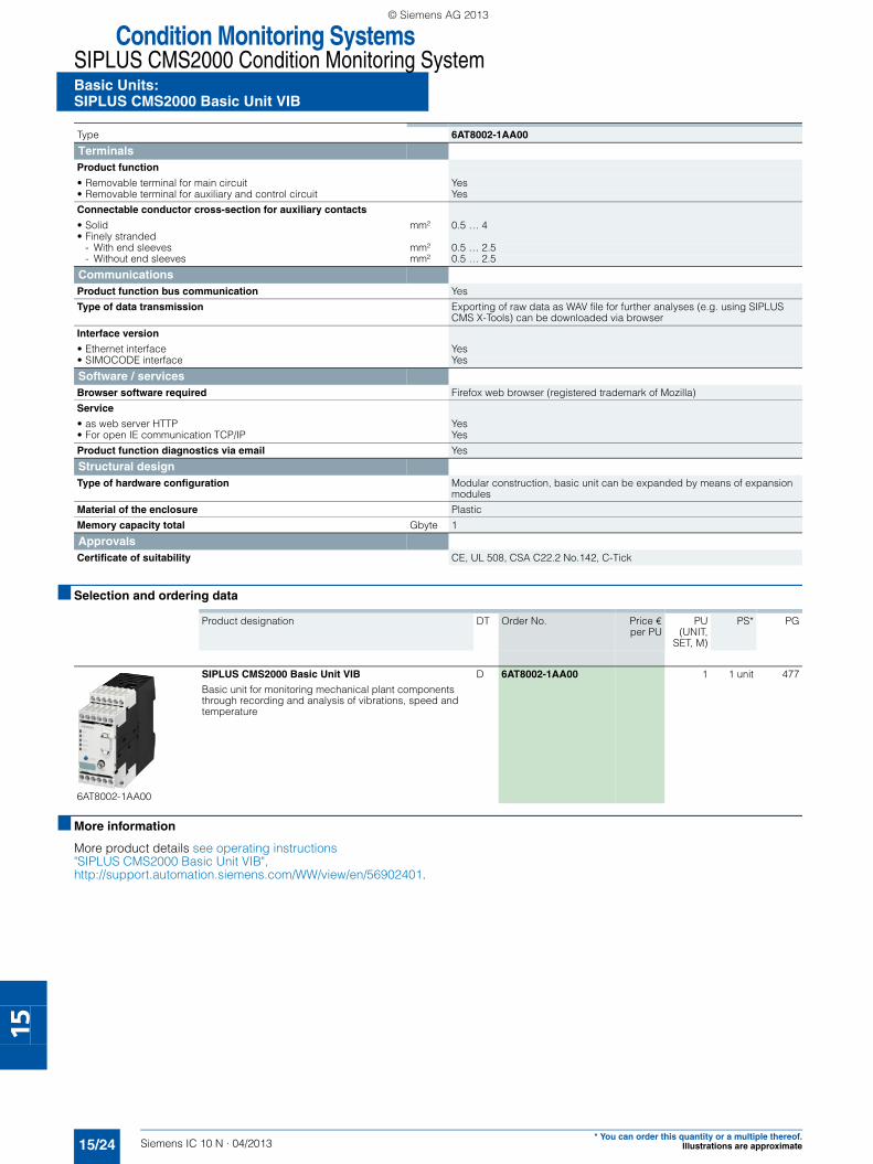
Condition Monitoring SystemsSIPLUS CMS2000 Condition Monitoring SystemBasic Units:SIPLUS CMS2000 Basic Unit VIB
15/24 Siemens IC 10 N · 04/2013* You can order this quantity or a multiple thereof.
Illustrations are approximate
15
■ Selection and ordering data
■ More information
More product details see operating instructions "SIPLUS CMS2000 Basic Unit VIB", http://support.automation.siemens.com/WW/view/en/56902401.
TerminalsProduct function
• Removable terminal for main circuit Yes• Removable terminal for auxiliary and control circuit Yes
Connectable conductor cross-section for auxiliary contacts
• Solid mm² 0.5 … 4• Finely stranded
- With end sleeves mm² 0.5 … 2.5- Without end sleeves mm² 0.5 … 2.5
CommunicationsProduct function bus communication Yes
Type of data transmission Exporting of raw data as WAV file for further analyses (e.g. using SIPLUS CMS X-Tools) can be downloaded via browser
Interface version
• Ethernet interface Yes• SIMOCODE interface Yes
Software / servicesBrowser software required Firefox web browser (registered trademark of Mozilla)
Service
• as web server HTTP Yes• For open IE communication TCP/IP Yes
Product function diagnostics via email Yes
Structural designType of hardware configuration Modular construction, basic unit can be expanded by means of expansion
modules
Material of the enclosure Plastic
Memory capacity total Gbyte 1
ApprovalsCertificate of suitability CE, UL 508, CSA C22.2 No.142, C-Tick
Type 6AT8002-1AA00
Product designation DT Order No. Price €
per PUPU
(UNIT,SET, M)
PS* PG
6AT8002-1AA00
SIPLUS CMS2000 Basic Unit VIB
Basic unit for monitoring mechanical plant components through recording and analysis of vibrations, speed and temperature
D 6AT8002-1AA00 1 1 unit 477
SIRIUS_IC10N_German_2013-04.book Seite 24 Freitag, 17. Mai 2013 10:32 10
© Siemens AG 2013

Condition Monitoring SystemsSIPLUS CMS2000 Condition Monitoring System
15/25Siemens IC 10 N · 04/2013
Expansion modules:SIPLUS CMS2000 VIB-MUX, temperature modules
15
■ Overview
SIPLUS CMS2000 VIB-MUX expansion modules and tempera-ture modules can be connected to the SIPLUS CMS2000 Basic Unit VIB via the SIMOCODE system interface.
SIPLUS CMS2000 VIB-MUX expansion modules
Up to two SIPLUS CMS2000 VIB-MUX expansion modules can be connected to SIPLUS CMS2000 Basic Unit VIB to expand the vibration channels. In this way, the number of vibration channels can be expanded modularly from 2 to a maximum of 16 chan-nels.
The following configuration options are possible:• Basic unit without expansion:
2 time-synchronous, continuously sampled vibration channels• Basic unit with one SIPLUS CMS2000 VIB-MUX:
8 + 1: 8 channels via the SIPLUS CMS2000 VIB-MUX in multi-plex mode, 1 channel continuous and independent of the channels connected on the SIPLUS CMS2000 VIB-MUX
• Basic unit with two SIPLUS CMS2000 VIB-MUX:16 vibration channels in multiplex mode
SIMOCODE connecting cable for connecting the SIPLUS CMS2000 Basic Unit VIB to the SIPLUS CMS2000 VIB-MUX see page 15/30.
SIPLUS CMS2000 VIB-MUX 6AT8002-2AA00 expansion module
Temperature modules
Up to two temperature modules can be connected to the SIPLUS CMS2000 Basic Unit VIB.
Each temperature module has three inputs for the connection of up to three analog temperature sensors (sensor types: Pt100/Pt1000, KTY83/KTY84 or NTC).
SIMOCODE connecting cable for connecting the SIPLUS CMS2000 Basic Unit VIB to the temperature modules see page 15/30.
3UF7700-1AA00-0 temperature module
SIRIUS_IC10N_German_2013-04.book Seite 25 Freitag, 17. Mai 2013 10:32 10
© Siemens AG 2013

Condition Monitoring SystemsSIPLUS CMS2000 Condition Monitoring SystemExpansion modules:SIPLUS CMS2000 VIB-MUX, temperature modules
15/26 Siemens IC 10 N · 04/2013
15
■ Technical specifications
SIPLUS CMS2000 VIB-MUX expansion modules
Temperature modules
Technical specifications see Catalog IC 10 ⋅ 2013, chapter 10, "Monitoring and Control Devices" → "Motor Management and SI-MOCODE 3UF7 Control Devices" → "Motor Management and SI-MOCODE pro 3UF7 Control Devices"
Type 6AT8002-2AA00
Product brand name SIPLUS
Product designation SIPLUS CMS2000 VIB-MUX
Product description Circuit of 8 IEPE measurement inputs on one IEPE output in multiplex opera-tion; channel control through the basic unit via the system interface
General data
IP degree of protection IP20
Ambient temperature
• During operation °C -20 … +65• During storage °C -25 … +85• During transport °C -25 … +85
Relative humidity without condensation
• During operation % 5 … 95
Physical measurement principle Vibration acceleration
Measuring range vibration frequency kHz 0.002 … 10
Equipment identifier
• According to DIN 40719 Expanded according to IEC 60204-2 Accord-ing to IEC 60750
P
• According to IEC 61346-2 P
Supply voltage
Type of voltage of the supply voltage DC
Supply voltage 1 at DC rated value V 24
Active power input maximum W 2.4
Mounting/fastening/dimensions
Mounting position Vertical
• Recommended Vertical
Type of mounting Standard mounting rail
Width mm 45
Height mm 106
Depth mm 124
Inputs/outputs
Number of sensor inputs
• For IEPE sensors 8
Number of outputs 1
Connections
Type of electrical connection
• of the inputs and outputs Screw terminals• for auxiliary and control circuit Screw terminals
Terminals
Product function
• Removable terminal for auxiliary and control circuit Yes• Removable terminal for main circuit Yes
Connectable conductor cross-section for auxiliary contacts
• Solid mm² 0.5 … 4• Finely stranded
- With end sleeves mm² 0.5 … 2.5- Without end sleeves mm² 0.5 … 2.5
Communications
Type of interface SIMOCODE interface Yes
Structural design
Material of the enclosure Plastic
Approvals
Certificate of suitability CE, UL 508, CSA C22.2 No.142, C-Tick
SIRIUS_IC10N_German_2013-04.book Seite 26 Freitag, 17. Mai 2013 10:32 10
© Siemens AG 2013

Condition Monitoring SystemsSIPLUS CMS2000 Condition Monitoring System
Expansion modules:SIPLUS CMS2000 VIB-MUX, temperature modules
15/27Siemens IC 10 N · 04/2013* You can order this quantity or a multiple thereof.Illustrations are approximate
15
■ Selection and ordering data
■ More information
More product details see the operating instructions "SIPLUS CMS2000", http://support.automation.siemens.com/WW/view/en/56901901.
More information about the 3UF7700-1AA00-0 temperature module see Catalog IC 10 ⋅ 2013, chapter 10, "Monitoring and Control Devices" → "Motor Management and SIMOCODE 3UF7 Control Devices" → "Motor Management and SIMOCODE pro 3UF7 Control Devices".
Product designation DT Order No. Price €
per PUPU
(UNIT,SET, M)
PS* PG
SIPLUS CMS2000 VIB-MUX expansion modules
6AT8002-2AA00
Up to two SIPLUS CMS2000 VIB-MUX expansion modules can be connected to SIPLUS CMS2000 Basic Unit VIB.
Up to 8 IEPE vibration channels can be connected to each expansion module.
D 6AT8002-2AA00 1 1 unit 477
Temperature modules
3UF7700-1AA00-0
Up to two temperature modules can be connected to the SIPLUS CMS2000 Basic Unit VIB.
Each temperature module has three inputs for the connec-tion of up to three temperature sensors.
} 3UF7700-1AA00-0 1 1 unit 42J
SIRIUS_IC10N_German_2013-04.book Seite 27 Freitag, 17. Mai 2013 10:32 10
© Siemens AG 2013

Condition Monitoring SystemsSIPLUS CMS2000 Condition Monitoring System
Accessories
15/28 Siemens IC 10 N · 04/2013
15
■ Overview
SIMOCODE connecting cable
SIMOCODE 3UF7930-0AA00-0 connecting cable
The connecting cable is used for connecting the SIPLUS CMS2000 Basic Unit VIB to the SIPLUS CMS2000 VIB-MUX ex-pansion modules and the temperature modules via the SIMO-CODE system bus interface.
The connecting cable with a length of 0.025 m must be used for side-by-side mounting of the basic unit and SIPLUS CMS2000 VIB-MUX expansion modules or temperature modules on a TH 35-15 standard mounting rail in accordance with IEC 60715.
Shield support
Shield support 6AT8002-4AA00
A separate shield support must be ordered for the EMC-compli-ant connection of signal and encoder cables to the SIPLUS CMS2000 Basic Unit VIB and the SIPLUS CMS2000 VIB-MUX expansion module.
The shield support comprises two shield clamps and five termi-nal clamps. One shield clamp is attached to the standard mount-ing rail above and one below the basic unit. The sensor cable shields are connected to the shield clamps by means of the ter-minal clamps.
VIB-SENSOR S01 vibration sensor
VIB-SENSOR S01 6AT8002-4AB00 vibration sensors
The VIB-SENSOR S01 vibration sensor with IEPE (Integrated Electronics Piezo-Electric) interface can be connected directly to the SIPLUS CMS2000 Basic Unit VIB and the SIPLUS CMS2000 VIB-MUX expansion module.
The sensor detects vibration accelerations in the frequency range from 0.5 Hz to 15 kHz with a resolution of 100 mV/g.
A threaded screw with an M8 male thread for mounting at the measuring point is included in the scope of delivery. The con-necting cable is connected to the vibration sensor via the MIL connector
CABLE-MIL connecting cable
CABLE-MIL connecting cables 6AT8002-4AC03, 6AT8002-4AC10
The VIB-SENSOR S01 vibration sensor is connected to the SIPLUS CMS2000 Basic Unit VIB or the SIPLUS CMS2000 VIB-MUX expansion module by means of the CABLE-MIL connecting cable.
This high-quality industrial cable is made of black polyurethane and is assembled on one end with a MIL connector (MIL-C5015). The open cable end of the shielded two-wire cable is connected directly to the screw terminals of the basic unit.
The connecting cable is available in lengths of 3 and 10 m.
SIRIUS_IC10N_German_2013-04.book Seite 28 Freitag, 17. Mai 2013 10:32 10
© Siemens AG 2013

Condition Monitoring SystemsSIPLUS CMS2000 Condition Monitoring System
15/29Siemens IC 10 N · 04/2013
Accessories
15
■ Technical specifications
SIMOCODE connecting cable
Shield support
VIB-SENSOR S01 vibration sensor
CABLE-MIL connecting cable
Type 3UF7930-0AA00-0
Product brand name SIRIUS
Product designation Connecting cable
General data
Ambient temperature
• During operation °C -25 … +60• During storage °C -40 … +80• During transport °C -40 … +80
Relative air humidity
• During operation % 5 … 95
Type 6AT8002-4AA00
Product brand name SIPLUS
Product designation SIPLUS CMS2000 shield support
Product description 3-fold shield support for EMC-compliant connection of signal and encoder cables
General data
Type of mounting Standard mounting rail
Number of signal cables connectable to the shield support
3
Type 6AT8002-4AB00
Product brand name SIPLUS
Product designation VIB-SENSOR S01
General data
Physical measurement principle Piezo-quartz sensor with integrated evaluation electronics
Frequency of the sensor operating range
• At ± 3 dB Hz 0.5 … 15 000
Sensitivity of the vibration acceleration sen-sor typical
mV/g 100
Resolution of measured value of vibration acceleration of sensor minimum
g 0.002
Measuring range vibration acceleration Full-scale value
g 50
Resonance frequency Hz 23 000
Signal voltage
• At DC V 10 … 14
Type of power supply IEPE 2 to 10 mA
Type of connection method MIL-C5015
Cable length maximum m 80
Ambient conditions
IP degree of protection IP65
Operating temperature °C -50 … +120
Design
Material of the enclosure High-grade steel
Mounting type other mounting Note
Including mounting bolts UNF1/4-28 on M8
Type 6AT8002-4AC03 6AT8002-4AC10
Product brand name SIPLUS
Product designation CABLE-MIL-300 connecting cable CABLE-MIL-1000 connecting cable
Product category Industrial cables
General data
Type of connection method MIL-C5015 / open cable end
Type of insulation Black polyurethane
Design of shield Braided shielding with stranded drain wire
Operating temperature °C -25 … +122
Cable length m 3 10
SIRIUS_IC10N_German_2013-04.book Seite 29 Freitag, 17. Mai 2013 10:32 10
© Siemens AG 2013
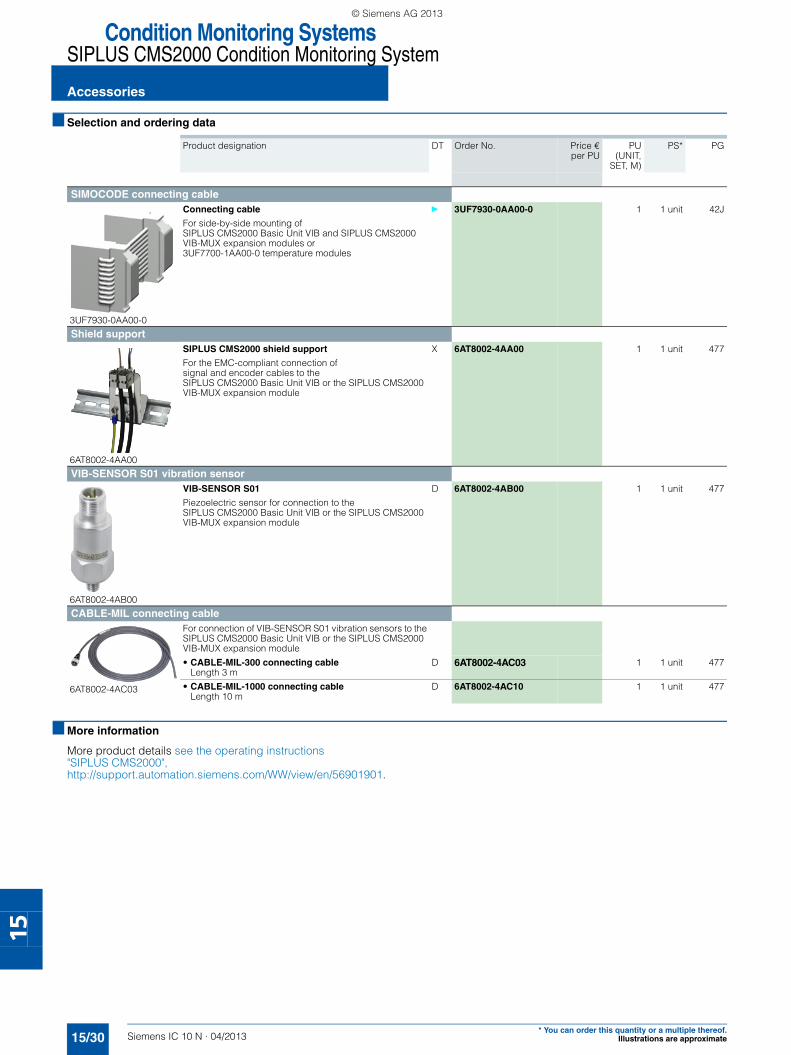
Condition Monitoring SystemsSIPLUS CMS2000 Condition Monitoring System
Accessories
15/30 Siemens IC 10 N · 04/2013* You can order this quantity or a multiple thereof.
Illustrations are approximate
15
■ Selection and ordering data
■ More information
More product details see the operating instructions "SIPLUS CMS2000", http://support.automation.siemens.com/WW/view/en/56901901.
Product designation DT Order No. Price €
per PUPU
(UNIT,SET, M)
PS* PG
SIMOCODE connecting cable
3UF7930-0AA00-0
Connecting cable
For side-by-side mounting of SIPLUS CMS2000 Basic Unit VIB and SIPLUS CMS2000 VIB-MUX expansion modules or3UF7700-1AA00-0 temperature modules
} 3UF7930-0AA00-0 1 1 unit 42J
Shield support
6AT8002-4AA00
SIPLUS CMS2000 shield support
For the EMC-compliant connection of signal and encoder cables to the SIPLUS CMS2000 Basic Unit VIB or the SIPLUS CMS2000 VIB-MUX expansion module
X 6AT8002-4AA00 1 1 unit 477
VIB-SENSOR S01 vibration sensor
6AT8002-4AB00
VIB-SENSOR S01
Piezoelectric sensor for connection to the SIPLUS CMS2000 Basic Unit VIB or the SIPLUS CMS2000 VIB-MUX expansion module
D 6AT8002-4AB00 1 1 unit 477
CABLE-MIL connecting cable
6AT8002-4AC03
For connection of VIB-SENSOR S01 vibration sensors to the SIPLUS CMS2000 Basic Unit VIB or the SIPLUS CMS2000 VIB-MUX expansion module
• CABLE-MIL-300 connecting cable Length 3 m
D 6AT8002-4AC03 1 1 unit 477
• CABLE-MIL-1000 connecting cable Length 10 m
D 6AT8002-4AC10 1 1 unit 477
SIRIUS_IC10N_German_2013-04.book Seite 30 Freitag, 17. Mai 2013 10:32 10
© Siemens AG 2013

Siemens IC 10 N · 04/2013
16
Siemens IC 10 N · 04/2013
16
16/2 Subject Index
16/3 Order No. Index
16/4 Conditions of sale and delivery, export regulations
Appendix
SIRIUS_IC10N_German_2013-04.book Seite 1 Freitag, 17. Mai 2013 10:32 10
© Siemens AG 2013
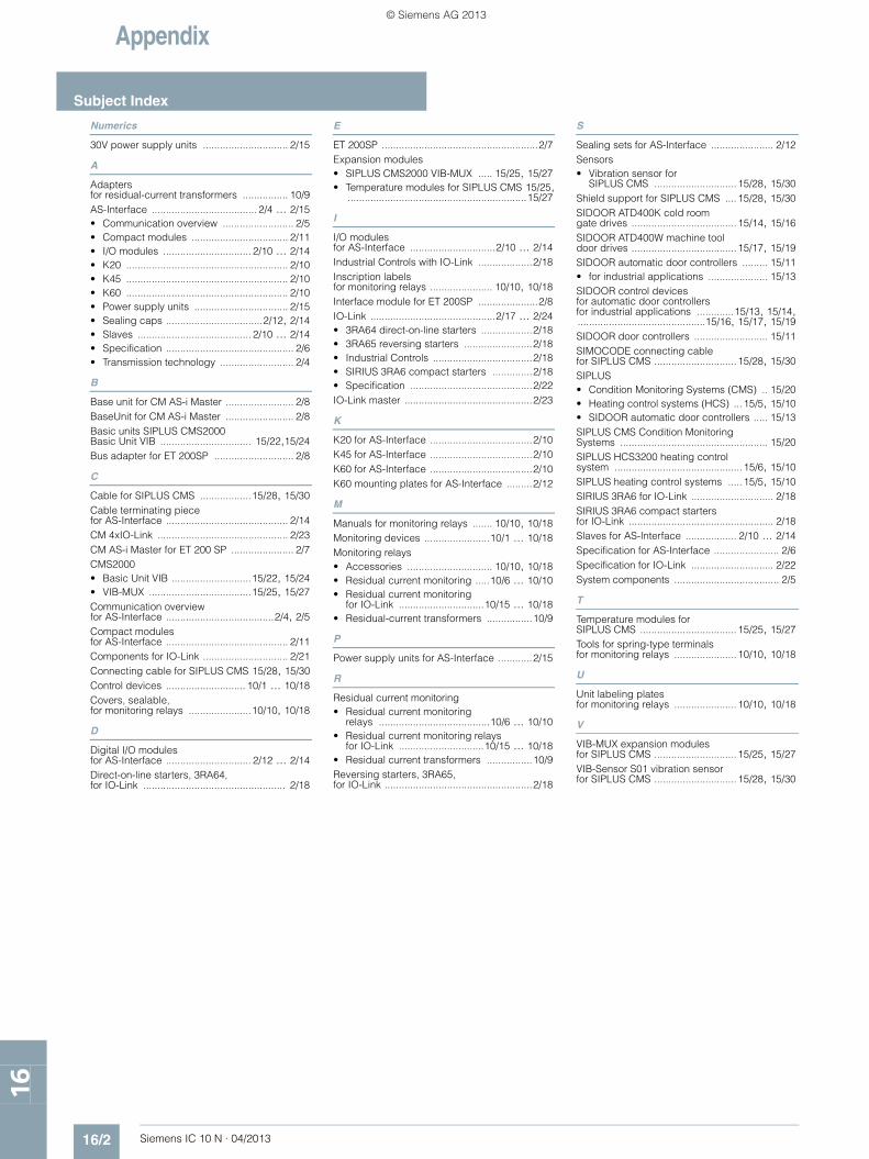
Appendix
Subject Index
16/2 Siemens IC 10 N · 04/2013
16
Numerics
30V power supply units .............................. 2/15
A
Adapters for residual-current transformers ................ 10/9AS-Interface ..................................... 2/4 ... 2/15• Communication overview ......................... 2/5• Compact modules .................................. 2/11• I/O modules ............................... 2/10 ... 2/14• K20 ......................................................... 2/10• K45 ......................................................... 2/10• K60 ......................................................... 2/10• Power supply units ................................. 2/15• Sealing caps ..................................2/12, 2/14• Slaves ........................................ 2/10 ... 2/14• Specification ............................................. 2/6• Transmission technology .......................... 2/4
B
Base unit for CM AS-i Master ........................ 2/8BaseUnit for CM AS-i Master ........................ 2/8Basic units SIPLUS CMS2000 Basic Unit VIB ................................ 15/22,15/24Bus adapter for ET 200SP ............................ 2/8
C
Cable for SIPLUS CMS ..................15/28, 15/30Cable terminating piece for AS-Interface ........................................... 2/14CM 4xIO-Link .............................................. 2/23CM AS-i Master for ET 200 SP ...................... 2/7CMS2000• Basic Unit VIB ............................15/22, 15/24• VIB-MUX ....................................15/25, 15/27Communication overview for AS-Interface ......................................2/4, 2/5Compact modules for AS-Interface ........................................... 2/11Components for IO-Link .............................. 2/21Connecting cable for SIPLUS CMS 15/28, 15/30Control devices ............................ 10/1 ... 10/18Covers, sealable, for monitoring relays ......................10/10, 10/18
D
Digital I/O modules for AS-Interface .............................. 2/12 ... 2/14Direct-on-line starters, 3RA64, for IO-Link .................................................. 2/18
E
ET 200SP .......................................................2/7Expansion modules• SIPLUS CMS2000 VIB-MUX ..... 15/25, 15/27• Temperature modules for SIPLUS CMS 15/25,
...............................................................15/27
I
I/O modules for AS-Interface ..............................2/10 ... 2/14Industrial Controls with IO-Link ...................2/18Inscription labels for monitoring relays ...................... 10/10, 10/18Interface module for ET 200SP .....................2/8IO-Link ............................................2/17 ... 2/24• 3RA64 direct-on-line starters ..................2/18• 3RA65 reversing starters ........................2/18• Industrial Controls ...................................2/18• SIRIUS 3RA6 compact starters ..............2/18• Specification ...........................................2/22IO-Link master .............................................2/23
K
K20 for AS-Interface ....................................2/10K45 for AS-Interface ....................................2/10K60 for AS-Interface ....................................2/10K60 mounting plates for AS-Interface .........2/12
M
Manuals for monitoring relays ....... 10/10, 10/18Monitoring devices .......................10/1 ... 10/18Monitoring relays• Accessories .............................. 10/10, 10/18• Residual current monitoring .....10/6 ... 10/10• Residual current monitoring
for IO-Link ..............................10/15 ... 10/18• Residual-current transformers ................10/9
P
Power supply units for AS-Interface ............2/15
R
Residual current monitoring• Residual current monitoring
relays .......................................10/6 ... 10/10• Residual current monitoring relays
for IO-Link ..............................10/15 ... 10/18• Residual current transformers ................10/9Reversing starters, 3RA65, for IO-Link ....................................................2/18
S
Sealing sets for AS-Interface ...................... 2/12Sensors• Vibration sensor for
SIPLUS CMS ............................. 15/28, 15/30Shield support for SIPLUS CMS .... 15/28, 15/30SIDOOR ATD400K cold room gate drives ..................................... 15/14, 15/16SIDOOR ATD400W machine tool door drives ..................................... 15/17, 15/19SIDOOR automatic door controllers ......... 15/11• for industrial applications ..................... 15/13SIDOOR control devices for automatic door controllers for industrial applications .............15/13, 15/14,.............................................15/16, 15/17, 15/19SIDOOR door controllers .......................... 15/11SIMOCODE connecting cable for SIPLUS CMS ............................. 15/28, 15/30SIPLUS• Condition Monitoring Systems (CMS) .. 15/20• Heating control systems (HCS) ...15/5, 15/10• SIDOOR automatic door controllers ..... 15/13SIPLUS CMS Condition Monitoring Systems .................................................... 15/20SIPLUS HCS3200 heating control system ............................................. 15/6, 15/10SIPLUS heating control systems ..... 15/5, 15/10SIRIUS 3RA6 for IO-Link ............................. 2/18SIRIUS 3RA6 compact starters for IO-Link ................................................... 2/18Slaves for AS-Interface .................. 2/10 ... 2/14Specification for AS-Interface ....................... 2/6Specification for IO-Link ............................. 2/22System components ..................................... 2/5
T
Temperature modules for SIPLUS CMS .................................. 15/25, 15/27Tools for spring-type terminals for monitoring relays ...................... 10/10, 10/18
U
Unit labeling plates for monitoring relays ...................... 10/10, 10/18
V
VIB-MUX expansion modules for SIPLUS CMS ............................. 15/25, 15/27VIB-Sensor S01 vibration sensor for SIPLUS CMS ............................. 15/28, 15/30
© Siemens AG 2013
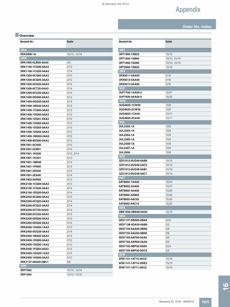
Appendix
16/3Siemens IC 10 N · 04/2013
Order No. Index
16
■ Overview
Bestell-Nr. Seite
3RA3RA2908-1A 10/10, 10/18
3RK3RK1005-0LB00-0AA0 2/3
3RK1100-1CQ00-0AA3 2/12
3RK1100-1CQ20-0AA3 2/14
3RK1200-0CQ00-0AA3 2/12
3RK1200-0CQ05-0AA3 2/12
3RK1200-0CQ20-0AA3 2/14
3RK1200-0CT20-0AA3 2/14
3RK1200-0CU20-0AA3 2/14
3RK1200-0DQ00-0AA3 2/12
3RK1400-0GQ20-0AA3 2/14
3RK1400-1BQ20-0AA3 2/14
3RK1400-1CQ00-0AA3 2/12
3RK1400-1DQ00-0AA3 2/12
3RK1400-1DQ01-0AA3 2/12
3RK1400-1DQ02-0AA3 2/12
3RK1400-1DQ03-0AA3 2/12
3RK1400-1DQ05-0AA3 2/12
3RK1400-1MQ00-0AA3 2/12
3RK1408-8SQ00-0AA3 2/12
3RK1901-0CA00 2/12
3RK1901-0CB01 2/12
3RK1901-1KA00 2/12, 2/14
3RK1901-1KA01 2/12
3RK1901-1MN00 2/14
3RK1901-1PN00 2/14
3RK1901-2DA00 2/14
3RK1901-2EA00 2/14
3RK1902-0AR00 2/12
3RK2100-1CQ00-0AA3 2/12
3RK2100-1CQ20-0AA3 2/14
3RK2100-1EQ20-0AA3 2/14
3RK2200-0CQ00-0AA3 2/12
3RK2200-0CQ20-0AA3 2/14
3RK2200-0CQ22-0AA3 2/14
3RK2200-0CT20-0AA3 2/14
3RK2200-0CU20-0AA3 2/14
3RK2200-0DQ00-0AA3 2/12
3RK2200-0DQ20-0AA3 2/14
3RK2200-1DQ00-1AA3 2/12
3RK2400-0GQ20-0AA3 2/14
3RK2400-1BQ20-0AA3 2/14
3RK2400-1DQ00-0AA3 2/12
3RK2400-1DQ00-1AA3 2/12
3RK2400-1FQ03-0AA3 2/12
3RK2400-1GQ20-1AA3 2/14
3RK2400-1HQ00-0AA3 2/12
3RK7137-6SA00-0BC1 2/8
3RP3RP1902 10/10, 10/18
3RP1903 10/10, 10/18
3RT3RT1900-1SB20 10/10
3RT1900-1SB60 10/10, 10/18
3RT1900-1SD60 10/10, 10/18
3RT2900-1SB20 10/18
3RX3RX9511-0AA00 2/16
3RX9512-0AA00 2/16
3RX9513-0AA00 2/16
3UF3UF7700-1AA00-0 15/27
3UF7930-0AA00-0 15/30
3UG3UG4625-1CW30 10/8
3UG4625-2CW30 10/8
3UG4825-1CA40 10/17
3UG4825-2CA40 10/17
3UL3UL2302-1A 10/9
3UL2303-1A 10/9
3UL2304-1A 10/9
3UL2305-1A 10/9
3UL2306-1A 10/9
3UL2307-1A 10/9
3UL2900 10/9
3ZX3ZX1012-0UG40-0AB0 10/10
3ZX1012-0UG40-0AC0 10/10
3ZX1012-0UG48-0AB1 10/18
3ZX1012-0UG48-0AC1 10/18
6AT6AT8002-1AA00 15/24
6AT8002-2AA00 15/27
6AT8002-4AA00 15/30
6AT8002-4AB00 15/30
6AT8002-4AC03 15/30
6AT8002-4AC10 15/30
6BK6BK1932-0BA00-0AA0 15/10
6ES6ES7137-6BD00-0BA0 2/24
6ES7138-4GA50-0AB0 2/3
6ES7155-6AA00-0BN0 2/8
6ES7155-6AU00-0BN0 2/8
6ES7193-6AF00-0AA0 2/9
6ES7193-6AR00-0AA0 2/9
6ES7193-6BP20-0DA0 2/24
6ES7193-6BP20-0DC0 2/9
6FB6FB1141-1AT10-3KU2 15/16
6FB1141-1AT10-3WE2 15/19
6FB1141-1AT11-3KU2 15/16
Bestell-Nr. Seite
SIRIUS_IC10N_German_2013-04.book Seite 3 Freitag, 17. Mai 2013 10:32 10
© Siemens AG 2013
Appendix
Conditions of sale and delivery
16/4 Siemens IC 10 N · 04/2013
16
■ 1. General Provisions
By using this catalog you can acquire hardware and software products described therein from Siemens AG subject to the following Terms and Conditions of Sale and Delivery (hereinafter referred to as "T&C"). Please note that the scope, the quality and the conditions for supplies and services, including software products, by any Siemens entity having a registered office outside Germany, shall be subject exclusively to the General Terms and Conditions of the respective Siemens entity. The following T&C apply exclusively for orders placed with Siemens Aktiengesellschaft, Germany.
1.1 For customers with a seat or registered office in GermanyFor customers with a seat or registered office in Germany, the following applies subordinate to the T&C:• the "General Terms of Payment"1) and,• for software products, the "General License Conditions for
Software Products for Automation and Drives for Customers with a Seat or Registered Office in Germany"1) and,
• for other supplies and services, the "General Conditions for the Supply of Products and Services of the Electrical and Electronics Industry"1).
1.2 For customers with a seat or registered office outside GermanyFor customers with a seat or registered office outside Germany, the following applies subordinate to the T&C:• the "General Terms of Payment"1) and,• for software products, the "General License Conditions for
Software Products for Automation and Drives for Customers with a Seat or Registered Office outside of Germany"1) and
• for other supplies and/or services, the "General Conditions for Supplies of Siemens Industry for Customers with a Seat or Registered Office outside of Germany"1).
■ 2. Prices
The prices are in € (Euro) ex point of delivery, exclusive of packaging.The sales tax (value added tax) is not included in the prices. It shall be charged separately at the respective rate according to the applicable statutory legal regulations.Prices are subject to change without prior notice. We will charget the prices valid at the time of delivery.To compensate for variations in the price of raw materials (e.g. silver, copper, aluminum, lead, gold, dysprosium and neodym), surcharges are calculated on a daily basis using the so-called metal factor for products containing these raw materials. A surcharge for the respective raw material is calculated as a supplement to the price of a product if the basic official price of the raw material in question is exceeded.The metal factor of a product indicates the basic official price (for those raw materials concerned) as of which the surcharges on the price of the product are applied, and with what method of calculation. An exact explanation of the metal factor can be downloaded at:www.siemens.com/automation/salesmaterial-as/catalog/en/ terms_of_trade_en.pdfTo calculate the surcharge (except in the cases of dysprosium and neodym), the official price from the day prior to that on which the order was received or the release order was effected is used.To calculate the surcharge applicable to dysprosium and neodym ("rare earths"), the corresponding three-month basic average price in the quarter prior to that in which the order was received or the release order was effected is used with a one-month buffer (details on the calculation can be found in the explanation of the metal factor).
■ 3. Additional Terms and Conditions
The dimensions are in mm. In Germany, according to the German law on units in measuring technology, data in inches apply only to devices for export.Illustrations are not binding.Insofar as there are no remarks on the individual pages of this catalog - especially with regard to data, dimensions and weights given - these are subject to change without prior notice.
■ 4. Export regulations
We shall not be obligated to fulfill any agreement if such fulfillment is prevented by any impediments arising out of national or international foreign trade or customs requirements or any embargoes and/or other sanctions.Export of goods listed in this catalog may be subject to licensing requirements. We will indicate in the delivery details whether licenses are required under German, European and US export lists. Goods labeled with "AL" not equal to "N" are subject to European or German export authorization when being exported out of the EU. Goods labeled with "ECCN" not equal to "N" are subject to US re-export authorization. The export indications can be viewed in advance in the description of the respective goods on the Industry Mall, our online catalog system. Only the export labels "AL" and "ECCN" indicated on order confirmations, delivery notes and invoices are authoritative.Even without a label, or with label "AL:N" or "ECCN:N", authori-zation may be required i .a. due to the final disposition and intended use of goods.If you transfer goods (hardware and/or software and/or technology as well as corresponding documentation, regardless of the mode of provision) delivered by us or works and services (including all kinds of technical support) performed by us to a third party worldwide, you must comply with all applicable national and international (re-)export control regulations.If required for the purpose of conducting export control checks, you (upon request by us) shall promptly provide us with all infor-mation pertaining to the particular end customer, final dispo-sition and intended use of goods delivered by us respectively works and services provided by us, as well as to any export control restrictions existing in this relation.The products listed in this catalog may be subject to European/German and/or US export regulations. Any export requiring approval is therefore subject to authorization by the relevant authorities.Errors excepted and subject to change without prior notice.
1) The text of the Terms and Conditions of Siemens AG can be downloaded at www.siemens.com/automation/salesmaterial-as/catalog/en/ terms_of_trade_en.pdf
IC10N_16_16_VuL.fm Seite 4 Freitag, 17. Mai 2013 3:43 15
© Siemens AG 2013

CatalogsIndustry Automation, Drive Technologies and Low-Voltage Power Distribution
Further information can be obtained from our branch officeslisted at www.siemens.com/automation/partner
System Solutions Interactive Catalog on DVD
Catalog
Products for Automation and Drives CA 01
Building ControlGAMMA Building Control ET G1
Drive SystemsVariable-Speed DrivesSINAMICS G130 Drive Converter Chassis Units SINAMICS G150 Drive Converter Cabinet Units
D 11
SINAMICS GM150, SINAMICS SM150 Medium-Voltage Converters
D 12
ROBICON Perfect Harmony Medium-Voltage Air-Cooled Drives Germany Edition
D 15.1
Digital: SINAMICS G180 Converters – Compact Units, Cabinet Systems, Cabinet Units Air-Cooled and Liquid-Cooled
D 18.1
SINAMICS S120 Chassis Format Units and Cabinet Modules SINAMICS S150 Converter Cabinet Units
D 21.3
SINAMICS DCM Converter Units D 23.1SINAMICS and Motors for Single-Axis Drives D 31Three-Phase Induction Motors SIMOTICS HV, SIMOTICS TN• Series H-compact• Series H-compact PLUS
D 84.1
Asynchronous Motors Standardline D 86.1Synchronous Motors with Permanent-Magnet Technology, HT-direct
D 86.2
DC Motors DA 12SIMOREG DC MASTER 6RA70 Digital Chassis Converters
DA 21.1
SIMOREG K 6RA22 Analog Chassis Converters DA 21.2Digital: SIMOREG DC MASTER 6RM70 Digital
Converter Cabinet UnitsDA 22
SIMOVERT PM Modular Converter Systems DA 45SIEMOSYN Motors DA 48MICROMASTER 420/430/440 Inverters DA 51.2MICROMASTER 411/COMBIMASTER 411 DA 51.3SIMOVERT MASTERDRIVES Vector Control DA 65.10SIMOVERT MASTERDRIVES Motion Control DA 65.11Synchronous and asynchronous servomotors for SIMOVERT MASTERDRIVES
DA 65.3
SIMODRIVE 611 universal and POSMO DA 65.4Note: Additional catalogs on SIMODRIVE or SINAMICS drive systems and SIMOTICS motors with SINUMERIK and SIMOTION can be found under Motion Control
Low-Voltage Three-Phase-MotorsSIMOTICS Low-Voltage Motors D 81.1MOTOX Geared Motors D 87.1SIMOGEAR Geared Motors MD 50.1
Mechanical Driving MachinesFLENDER Standard Couplings MD 10.1FLENDER High Performance Couplings MD 10.2FLENDER SIG Standard industrial gear unit MD 30.1FLENDER SIP Standard industrial planetary gear units MD 31.1
Process Instrumentation and AnalyticsField Instruments for Process Automation FI 01Digital: SIPART Controllers and Software MP 31Products for Weighing Technology WT 10Digital: Process Analytical Instruments PA 01Digital: Process Analytics,
Components for the System IntegrationPA 11
Digital: These catalogs are only available as a PDF and/or as an e-book.
Low-Voltage Power Distribution and Electrical Installation Technology
Catalog
SENTRON Protection, Switching, Measuring and Monitoring Devices
LV 10.1
SIVACON · ALPHA Switchboards and Distribution Systems
LV 10.2
Standards-Compliant Components for Photovoltaic Plants
LV 11
3WT Air Circuit Breakers up to 4000 A LV 353VT Molded Case Circuit Breakers up to 1600 A LV 36Digital: SIVACON System Cubicles, System Lighting
and System Air-ConditioningLV 50
Digital: ALPHA Distribution Systems LV 51ALPHA FIX Terminal Blocks LV 52SIVACON S4 Power Distribution Boards LV 56SIVACON 8PS Busbar Trunking Systems LV 70
Motion ControlSINUMERIK & SIMODRIVE Automation Systems for Machine Tools
NC 60
SINUMERIK & SINAMICS Equipment for Machine Tools
NC 61
SINUMERIK 840D sl Type 1B Equipment for Machine Tools
NC 62
SINUMERIK 808D, SINAMICS V60 and G120, SIMOTICS 1FL5 and 1LE1
NC 81.1
SINUMERIK 828D BASIC T/BASIC M, SINAMICS S120 Combi, 1FK7 and 1PH8 motors
NC 82
SIMOTION, SINAMICS S120 & SIMOTICSEquipment for Production Machines
PM 21
Drive and Control Components for Cranes CR 1
Power Supply and System CablingPower supply SITOP KT 10.1
Safety IntegratedSafety Technology for Factory Automation SI 10
SIMATIC HMI/PC-based AutomationHuman Machine Interface Systems/PC-based Automation
ST 80/ ST PC
SIMATIC IdentIndustrial Identification Systems ID 10
SIMATIC Industrial Automation SystemsProducts for Totally Integrated Automation ST 70SIMATIC PCS 7 Process Control System ST PCS 7Add-ons for the SIMATIC PCS 7 Process Control System
ST PCS 7.1
Digital: Migration solutions with the SIMATIC PCS 7 Process Control System
ST PCS 7.2
SIMATIC NETIndustrial Communication IK PI
SINVERT PhotovoltaicsInverters and Components for Photovoltaic Installations RE 10
SIRIUS Industrial Controls SIRIUS Industrial Controls IC 10
Information and Download Center
PDF versions of the catalogs are available on the Internet at:www.siemens.com/industry/infocenter
Please note the section “Downloading catalogs” on page “Online services” in the appendix of this catalog.
© Siemens AG 2013

Get more information
Control Components and Systems Engineering:www.siemens.com/sirius
The information provided in this catalog news contains descriptions or characteristics of performance which in case of actual use do not always apply as described or which may change as a result of further development of the products. An obligation to provide the respective characteristics shall only exist if expressly agreed in the terms of contract. Availability and technical specifications are subject to change without notice.All product designations may be trademarks or product names of Siemens AG or supplier companies whose use by third parties for their own purposes could violate the rights of the owners.
Siemens AGIndustry SectorControl Components andSystems EngineeringPostfach 235590713 FÜRTHGERMANY
Subject to change without prior noticePDF/E-Book (Order No. E86060-K1010-A151-A3-7600)MP.R3.CP.0000.00.3.20KG 0513 86 En© Siemens AG 2013
www.siemens.com/automation
IC10N_201304_umschlag_ENG.indd 2IC10N_201304_umschlag_ENG.indd 2 17.05.2013 13:40:5817.05.2013 13:40:58
© Siemens AG 2013