Catalog HY08-1114-1/NA - Sections A and B - Coastal Hydraulics Interchange... · Basic Most of the...
64
Heavy Duty Hydraulic Cylinders Series 2H Parker Hannifin Corporation Cylinder Division Des Plaines, Illinois USA www.parker.com/cylinder Catalog HY08-4-/NA A Series 2H Heavy Duty Hydraulic Cylinders 1.50" Through 6.00" Bore Performance 2 Specifications and Mounting Styles 3 Cylinder Features 4-5 Application Check List 6 Mounting Styles & Tips for Applying 7 2H Cylinder Model Code & How To Order 8-9 Rod End Styles and Dimensions 0- TD, TB, TC Mount Dimensions 2 J Mount Dimensions 3 JB Mount Dimensions 4 JJ Mount Dimensions 5 H Mount Dimensions 6 HB Mount Dimensions 7 HH Mount Dimensions 8 C Mount Dimensions 9 F Mount Dimensions 20 BB Mount Dimensions 2 D Mount Dimensions 22 DB Mount Dimensions 23 DD Mount Dimensions 24 DE Mount Dimensions 25 SB Mount Dimensions 26 Double Rod End Cylinders 27 2HD & 3HD Bolt-On Gland Option 28 Section A Overview Section A
-
Upload
truongmien -
Category
Documents
-
view
214 -
download
1
Transcript of Catalog HY08-1114-1/NA - Sections A and B - Coastal Hydraulics Interchange... · Basic Most of the...

Heavy Duty Hydraulic CylindersSeries 2H
� Parker Hannifin CorporationCylinder DivisionDes Plaines, Illinois USAwww.parker.com/cylinder
Catalog HY08-���4-�/NA
A
Series 2H Heavy Duty Hydraulic Cylinders1.50" Through 6.00" Bore
Performance 2
Specifications and Mounting Styles 3
Cylinder Features 4-5
Application Check List 6
Mounting Styles & Tips for Applying 7
2H Cylinder Model Code & How To Order 8-9
Rod End Styles and Dimensions �0-��
TD, TB, TC Mount Dimensions �2
J Mount Dimensions �3
JB Mount Dimensions �4
JJ Mount Dimensions �5
H Mount Dimensions �6
HB Mount Dimensions �7
HH Mount Dimensions �8
C Mount Dimensions �9
F Mount Dimensions 20
BB Mount Dimensions 2�
D Mount Dimensions 22
DB Mount Dimensions 23
DD Mount Dimensions 24
DE Mount Dimensions 25
SB Mount Dimensions 26
Double Rod End Cylinders 27
2HD & 3HD Bolt-On Gland Option 28
Section A Overview
Section A

Heavy Duty Hydraulic CylindersSeries 2H
2 Parker Hannifin CorporationCylinder DivisionDes Plaines, Illinois USAwww.parker.com/cylinder
Catalog HY08-���4-�/NA
Parker Series 2H Heavy Duty Hydraulic CylinderSeries 2H cylinders set the standard for performance, durability, and trouble free operation. Parker superior design, the use of high quality materials and stringent manufacturing practices provide all customers with long cylinder service life and reduced operating costs. Patented design features such as the “Jewel” rod gland, hard chrome plated piston rods, and stepped cushions provide increased machine productivity through reduced downtime, faster cycle times, and improved system efficiency. Every Parker cylinder is individually tested before leaving our plant to assure proper performance and leak free operation. All Parker Cylinder products carry an �8 month warranty.
Select Parker Series 2H cylinder for your hydraulic cylinder requirements. Parker Series 2H will provide the value and performance you need for all of your industrial hydraulic application demands.
Performance

Heavy Duty Hydraulic CylindersSeries 2H
3 Parker Hannifin CorporationCylinder DivisionDes Plaines, Illinois USAwww.parker.com/cylinder
Catalog HY08-���4-�/NA
A
Standard Specifications• Heavy Duty Service – ANSI/(NFPA) T3.6.7R2 - �996 Specifications and Mounting Dimension Standards• Standard Construction – Square Head – Tie Rod Design• Nominal Pressure – 3000 psi�
• Standard Fluid – Hydraulic Oil• Standard Temperature – -�0°F to +�65°F2
• Bore Diameters – �.50" through 6.00" (Larger sizes available)
Tie Rods Extended Both Ends
Head Rectangular Flange Head Square Flange Head Rectangular Cap Rectangular Flange
Cap Square Flange
(NFPA ME5)
Style JJ�.50" - 6.00"
(NFPA MF2)
Style H�.50" - 6.00"
(NFPA MF6)
Style HB�.50" - 6.00"
(NFPA MF5)
Style JB�.50" -
6.00"
(NFPA MX3) (NFPA MX2)
Style TC�.50" - 6.00"
(NFPA MX�)
Style TD�.50" - 6.00"
(NFPA MF�)
Style J�.50" - 6.00"
Cap Rectangular Side Lug Side Tapped
(NFPA MS2)
Style C �.50" - 6.00"
(NFPA MS4)
Style F �.50" - 6.00"
(NFPA ME6)
Style HH�.50" - 6.00"
Cap Fixed Clevis
(NFPA MP�)
Style BB �.50" - 6.00"
(NFPA MT�)
Style D �.50" - 6.00"
Double Rod Cylinders
Head Trunnion
Style KT Shown �.50" - 6.00"
Cap Trunnion Intermediate Fixed Trunnion
Spherical Bearing
(NFPA MT4)
Style DD �.50" - 6.00"
Style SB �.50" - 6.00"
(NFPA MT2)
Style DB �.50" - 6.00"
Available Mounting Styles
Note: Series 2H Hydraulic Cylinders fully meet ANSI/(NFPA) T3.6.7R2 - �996 Specifications and Mounting Dimension Standards for Square Head Industrial Fluid Power Cylinders.
Tie Rods Extended Head End
Style TB�.50" - 6.00"
Tie Rods Extended Cap End
• Piston Rod Diameter – .625" through 4.000"• Mounting Styles – �8 standard styles at various application ratings• Strokes – Available in any practical stroke length• Cushions – Optional at either end or both ends of stroke. “Float Check” at cap end.• Rod Ends – Four Standard Choices – Specials to Order� If hydraulic operating pressure exceeds 3000 psi, send application data for engineering evaluation and recommendation. See Section E for actual design factors.2 See Section E for higher temperature service.
In line with our policy of continuing product improvement, specifications in this catalog are subject to change.
Specifications
Style DE 4.00" - 6.00"
HD Intermediate Fixed Trunnion
(NFPA MT4)
(NFPA MX0)
Style T�.50" - 6.00"
Basic
Most of the above illustrated mounting styles are available in double rod cylinders.

Heavy Duty Hydraulic CylindersSeries 2H
4 Parker Hannifin CorporationCylinder DivisionDes Plaines, Illinois USAwww.parker.com/cylinder
Catalog HY08-���4-�/NA
The inside story on why Series 2H is your best choice in heavy duty hydraulic cylinders
Parker’s Exclusive Stepped floating cushions combine the best features of known cushion technology.Deceleration devices or built-in “cushions” are optional and can be supplied at head end, cap end, or both ends without change in envelope or mounting dimensions. Parker cylinder cushions are a stepped design and combine the best features of known cushion technology.
Standard straight or tapered cushions have been used in industrial cylinders over a very broad range of applications. Parker research has found that both designs have their limitations.
As a result, Parker has taken a new approach in cushioning of industrial hydraulic cylinders and for specific load and velocity conditions have been able to obtain deceleration curves that come very close to the ideal. The success lies in a stepped sleeve or spear concept where the steps are calculated to approximate theoretical orifice area curves.
In the cushion performance chart, pressure traces show the results of typical orifice flow conditions. Tests of a three-step sleeve or spear show three pressure pulses coinciding with the
Piston Rod Stud – Furnished on 2.000" diameter rods and smaller when standard style #4 rod end threads are required.Studs have rolled threads and are made from high strength steel. Anaerobic adhesive is used to permanently lock the stud to the piston rod.
High Strength Tie Rods – Made from �00,000 psi minimum yield steel with rolled threads for added strength.
Steel Head – Bored and grooved to provide concentricity for mating parts.
steps. The deceleration cushion plunger curves shape comes very close to being theoretical, with the exception of the last �/2 inch of travel. This is a constant shape in order to have some flexibility in application. The stepped cushion design shows reduced pressure peaks for most load and speed conditions, with comparable reduction of objectionable stopping forces being transmitted to the load and the support structure.
All Parker Hannifin cushions are adjustable.
The Series 2H cylinder design incorporates the longest cushion sleeve and cushion spear that can be provided in the standard envelope without decreasing the rod bearing and piston bearing strengths.
Primary Seal – TS-2000 Rod Seal is a proven leakproof design – completely self-compensating and self-relieving to withstand variations and conform to mechanical deflection that may occur.
Secondary Seal – Double-Service Wiperseal® (Hannifin Patent #2907596) – wipes clean any oil film adhering to the rod on the extend stroke and cleans the rod on the return stroke.
Piston Rod – Medium carbon steel, induction case-hardened, hard chrome-plated and polished to �0 RMS finish. Piston rods are made from 90,000 to �00,000 psi minimum yield material in .625" through 4.000" diameters. Larger diameters vary between 57,000 and 90,000 psi minimum material, depending on rod diameter.
Ports – SAE “O” ring ports are standard.
Optional PortsPorts – NPTF ports are optional at no extra charge. Oversize NPTF and SAE ports are available at extra charge.
Features and Benefits
“Jewel” Rod Gland Assembly – Externally removable without cylinder disassembly. Long bearing surface is inboard of the seals, assuring positive lubrication from within the cylinder. An o-ring is used as a seal between gland and head, and also serves as a prevailing torque-type lock.
End Seals – Pressure-actuated cylinder body-to-head and cap o-rings.

Heavy Duty Hydraulic CylindersSeries 2H
5 Parker Hannifin CorporationCylinder DivisionDes Plaines, Illinois USAwww.parker.com/cylinder
Catalog HY08-���4-�/NA
A
Adjustable Floating Stepped Cushions – For maximum performance – economical and flexible for even the most demanding applications – provides superior performance in reducing shock. Cushions are optional and can be supplied at head end, cap end, or both ends without change in envelope or mounting dimensions.
Cylinder Body – Heavy-wall steel tubing, honed to a micro finish bore.
OPTIONAL PISTONS
PHENOLICBEARINGS
SYNTHETIC RUBBEREXPANDER RINGS
BRONZEFILLED PTFE
TEFLON RINGS
Steel Cap – Bored and grooved to provide concentricity for mating parts.
(�) When a cushion is specified at the head end:
a. A self-centering stepped sleeve is furnished on the piston rod assembly.
b. A needle valve is provided that is flush with the side of the head even when wide open. It may be identified by the fact that it is socket-keyed. It is located on side number 2, in all mounting styles except D, DB, DD, DE, JJ, and HH. In these styles it is located on side number 3. c. On 6.00" bore and larger cylinders a springless check valve is provided that is also flush with the side of the head and is mounted adjacent to the needle valve except on mounting style C, where it is mounted opposite the needle valve. It may be identified by the fact that it is slotted. d. On �.50" - 5.00" bore cylinders a slotted sleeve design is used in place of the check valve.
STEPPED CUSHIONSCAP END SPEARROD END SLEEVE
Optional Pistons
Hi Load Piston – Optional at extra charge. Includes wear rings and bronze-filled PTFE seals. Two wear rings serve as bearings which deform radially under side-loading, enabling the load to be spread over a larger area and reduce unit loading. Bronze-filled PTFE seals are
designed for extrusion-free, leak-proof service and longer cylinder life than the lipseal type piston.
Figure A
e. �.50" - 2.50" bore cylinders use a cartridge style needle valve (see Figure A).
(2) When a cushion is specified at the cap end: a. A stepped cushion spear is provided on the piston rod. b. A “float check” self-centering bushing is provided which incorporates a large flow check valve for fast “out-stroke” action. c. A socket-keyed needle valve is provided that is flush with the side of the cap when wide open. It is located on side number 2 in all mounting styles except D, DB, DD, DE, JJ, and HH. In these styles it is located on side number 3.
Features and Benefits
Align-A-Groove – (Patent #3043639) – A 3/�6" wide surface machined at each end of the cylinder body. Makes precise mounting quick and easy.
Optional High Temperature Gland – Dual filled PTFE rod seals and filled PTFE wiper seal are energized with fluorocarbon o-rings to maintain consistent contact with the piston rod. Excellent sealing performance produce dry rod on extend stroke with rod scraping to clean
rod on retract. Combine with Spring Loaded PTFE Piston Seals for cylinder heat resistance to 400° F. See class 8 seal specification on Operating Fluids and Temperature Range page.
One-Piece Nodular Iron Piston – The wide piston surface contacting cylinder bore reduces bearing loads. Anaerobic adhesive is used to permanently lock and seal the piston to the rod.
Lipseal® Piston – Zero leakage under static conditions for hydraulic pressures up to 3000 PSI. Seals are self-compensating to conform to variations in pressure, mechanical deflection, and wear. Back-up washer prevents extrusion.
Spring Loaded PTFE Piston SealsOptional filled PTFE piston Lipseals utilize an internal stainless steel spring to
energize both the dynamic and static sealing lips to optimize seal performance throughout the operating temperature range. Non-metallic piston wear ring in �.50"-6.00" bores (bronze in 7.00" & 8.00" bore 3H) reduces possibility of damaging piston which can score expensive tubing. Combine with High Temperature Gland for cylinder heat resistance to 400° F. See class 8 seal specification on Operating Fluids and Temperature Range page.
Step cut iron piston rings are optional at no extra charge.

Heavy Duty Hydraulic CylindersSeries 2H
6 Parker Hannifin CorporationCylinder DivisionDes Plaines, Illinois USAwww.parker.com/cylinder
Catalog HY08-���4-�/NA
Application ChecklistThe following checklist should used to select the best possible cylinder for a given application. Additional information can be referenced in the following pages to help assist in this process. In the event that you have additional questions or concerns, or if more information is required, please contact your local Parker distributor or our customer service representatives for assistance.
1. Establish the system requirements ........................................................................................................ Series 2H • How heavy is the load to be moved? • What is the nominal operating pressure of the system? • How far does the load have to move? • What is the speed at which the load will move? • What is the fluid type and the temperature to which the cylinder will be exposed?
2. Mounting Style .......................................................................................................................................... Page 7 • Determine the best mounting style for the application.
3. Cylinder Bore and Operating Pressure ................................................................................................... Page 96 • Review the theoretical push and pull force for a given bore size to determine.
4. Piston Rod .................................................................................................................................................. Page �04 • Determine what rod size will be required to avoid buckling. • Determine if a single or double rod cylinder is required. • Determine the rod end style and rod end thread. • Will stop tubing be required?
5. Piston Seals ............................................................................................................................................... Page 99 • Determine the best seal type for your application. • Select the proper seal type and configuration for the application. • Select the proper seal to assure fluid and temperature compatibility.
6. Cushioning ................................................................................................................................................ Page �06 • Determine if cushions are required to safely stop the load.
7. Ports ........................................................................................................................................................... Page �0� • Select the best possible port size for a given speed requirement. • Select port position.
8. Piston rod and mounting accessories ................................................................................................... Page 66 • Determine how you will attach the cylinder to the load.
9. Optional accessories and modifications ............................................................................................... Page 65
Application Checklist

Heavy Duty Hydraulic CylindersSeries 2H
7 Parker Hannifin CorporationCylinder DivisionDes Plaines, Illinois USAwww.parker.com/cylinder
Catalog HY08-���4-�/NA
A
Application: • Straight line force transfer • Compression loads (push) – use TC or TD • Tension loads (pull) – use TB or TD
Mounting Styles & Tips for Applying ThemExtended Tie Rod Mountings – TB, TC, and TD
Advantages: • Ease of mounting in tight spaces • Force is transferred along the centerline of the cylinder
Application: • Straight line force transfer • Compression loads (push) – use H, HB or HH • Tension loads (pull) – use J, JB, or JJ
Flange Mountings – J, JB, JJ, H, HB, and HHAdvantages: • Rigid base mounting due to large flange area • Force is transferred along the centerline of the cylinder
Application: • Straight line force transfer • Can be used in compression or tension loads • Thrust key and secure mounting area are vital
Side Tap Mounting – F / Side Lug Mounting – CAdvantages: • Ease of mounting
Application: • Curved or arc line force transfer • Can be used in compression or tension loads • Movement in a simple arc – use BB mountings • Movement in a compound arc – use SB mountings
Pivot Mountings – BB and SBAdvantages: • Ease of mounting • Design flexibility • Self aligning (SB)
Application: • Curved or arc line force transfer • Can be used in compression or tension loads • Compression loads – use DB or DD, DE mountings • Tension loads – use D, DD or DE mountings
Trunnion Mountings – D, DB, DD and DEAdvantages: • Ease of mounting • Design flexibility • Self aligning
Mounting Style Tips

Heavy Duty Hydraulic CylindersSeries 2H
8 Parker Hannifin CorporationCylinder DivisionDes Plaines, Illinois USAwww.parker.com/cylinder
Catalog HY08-���4-�/NA
2H Model Code
How To Order
Shaded boxes identify required model number fields.
� Available mounting styles for K Type cylinders are located at the end of Section A. When ordering a double rod end cylinder, the piston rod number and piston rod end threads are to be specified for both rod ends. The model number should be created as viewing the primary rod end on the left hand side. Example: K Type Cylinder: 4.00CKTD2HLT�4A28AC�0.0002 Mounting Styles C and F should have a minimum stroke length equal to or greater than their bore size.3 Specify XI dimension.4 In general, the model numbers as read left to right corresponding to the cylinder as
viewed from left to right with the primary end at the left. The second or subsequent mountings are mountings called out as they appear in the assembly moving away from the rod end. Except when tie rod extension mountings are part of a combination, all combinations should have a “S” (Special) in the model code and a note in the body of the order clarifying the mounting arrangement. The “P”, as used to define a thrust key is not considered to be a mounting. However it is located at the primary end.
5.00
Bore Dia.
Specify bore dia. in inches
�.50 2.00 2.50 3.25 4.00 5.00 6.00
Use “C” only if head end cushion is required.
C K F P 2H C T
Double Rod EndCylinder
Use “K” only if a double rod end cylinder is required.�
Cushion Head
Mounting Style
T = Basic, No Mount TB = Tie Rods Ext. Head TC = Tie Rods Ext. Cap TD = Tie Rods Ext. Both Ends J = Head Rectangular Flange JB = Head Square Flange JJ = Head Rectangular H = Cap Rectangular Flange HB = Cap Square Flange HH = Cap Rectangular C = Side Lug2
F = Side Tapped2
BB = Cap Fixed Clevis D = Head Trunnion DB = Cap Trunnion DD = Int. Fixed Trunnion3
DE = Heavy Duty Intermediate Fixed Trunnion3
SB = Spherical Bearing
Mounting Modification
P = Use only if Thrust Key required. (Style C or F.)M = Use only for Manifold Port O-Ring Seal. Applies to C Mount only.
Series Designator
2H2HD
Piston Seal
C = Ring Packed Piston (std.)L = Lip Seal PistonK = Hi Load PistonF = Low FrictionS = Spring Loaded PTFE piston seals 3 = Magnetic Piston, stainless steel cylinder body, single bi-directional piston seal7 = Magnetic Piston, carbon steel body, single bi-directional piston seal
Ports
T = SAE Straight Thread O-Ring (Std.)U = NPTF Ports (Dry Seal Pipe Thread)R = BSP Ports (Parallel Thread ISO 228)P = SAE Flange Ports (3,000 psi)B = BSPT Ports (Taper Thread) G = Metric Thread Ports Y = Metric Thread Ports per ISO 6�49M = Used only for Manifold Port O-ring Seal. M option must be specified (Mounting Modification), applies to Mounting Style C only.
TB
Any practical mounting style listed.
Combination Mounts4

Heavy Duty Hydraulic CylindersSeries 2H
9 Parker Hannifin CorporationCylinder DivisionDes Plaines, Illinois USAwww.parker.com/cylinder
Catalog HY08-���4-�/NA
A
How To Order
2H Model Code
J
Common Modification5
J = High Water Content Fluid V = Fluorocarbon Seals W = Water Service X = EPR Seals 2 = Class 2 Seals 4 = Class 4 Seals E = Fluorocarbon Seals – Piston Rod only H = Class 8 Seals N = High Temperature Rod Gland6
Special Modification
S 1 4 A C 16.000
Use only if special modifications are required:Oversize PortsPort Position Change Special Seals Stop Tube7 Stroke Adjusters Tie Rod Supports Other
Piston Rod Number 8
�234
Piston Rod End
Style 4 Small Male Style 7 Female Thread for Spherical Rod Eye for Piston Rod Codes Larger than Code #� Style 8 Intermediate MaleStyle 9 Short Female9 Style 55 Rod End for Flange CouplingStyle 3 Special (Specify)�0
Piston Rod Threads
A = UNF Standard M = Metric��
Cushion Cap
Used only if cushion required
Stroke7
Specify in inches
Shaded boxes identify required model number fields.
5 See common modifications Section D for additional options.6 Energized PTFE rod seals & wiperseal. All other cylinder seals are fluorocarbon.7 S = Stop Tube. Specify: stop tube length, net stroke and gross stroke. Gross stroke = stop tube length + net stroke. Gross stroke to be placed in the model number field. Example: 2.000 inches long stop tube +�4.000 inches net stroke �6.000 inches gross stroke8 Refer to Rod buckling chart in Section E to assure rod number selected will not buckle under load.9 Style 9 stroke restrictions may apply. See Style 9 Minimum Stroke Table for details.�0 Provide dimensions for KK, A, W or WF. If otherwise special, furnish dimensioned sketch.�� See Section D for detailed information regarding standard metric rod end thread sizes.
Style 9 Minimum Stroke TableBore
ØRod
ØMinimum
Stroke
�.50 - 4.00 All None5.00 2.000 None
2.500 �.0003.000 �.3753.500 �.625
6.00 2.500 None3.000 �.3753.500 �.3754.000 2.000
Heavy Duty Hydraulic CylindersSeries 2H
�0 Parker Hannifin CorporationCylinder DivisionDes Plaines, Illinois USAwww.parker.com/cylinder
Catalog HY08-���4-�/NA
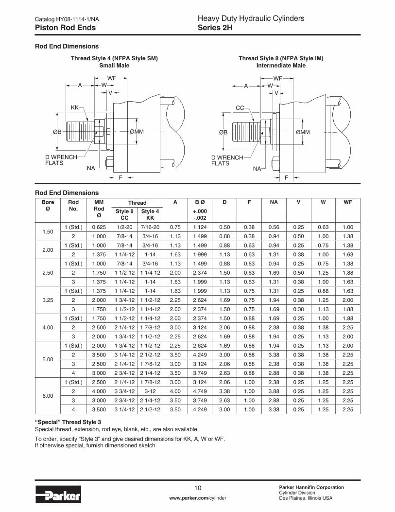
Rod End Dimensions
Thread Style 8 (NFPA Style IM)Intermediate Male
Thread Style 4 (NFPA Style SM)Small Male
“Special” Thread Style 3Special thread, extension, rod eye, blank, etc., are also available.
To order, specify “Style 3” and give desired dimensions for KK, A, W or WF. If otherwise special, furnish dimensioned sketch.
Piston Rod Ends
VA
CC
NA
W
D WRENCHFLATS
ØB Ø MM
WF
F
VA
KK
NA
W
D WRENCHFLATS
ØB Ø MM
WF
F
Bore Ø
Rod No.
MM Rod
Ø
Thread A B Ø D F NA V W WF
Style 8 CC
Style 4 KK
+.000 -.002
�.50� (Std.) 0.625 �/2-20 7/�6-20 0.75 �.�24 0.50 0.38 0.56 0.25 0.63 �.00
2 �.000 7/8-�4 3/4-�6 �.�3 �.499 0.88 0.38 0.94 0.50 �.00 �.38
2.00� (Std.) �.000 7/8-�4 3/4-�6 �.�3 �.499 0.88 0.63 0.94 0.25 0.75 �.38
2 �.375 � �/4-�2 �-�4 �.63 �.999 �.�3 0.63 �.3� 0.38 �.00 �.63
2.50
� (Std.) �.000 7/8-�4 3/4-�6 �.�3 �.499 0.88 0.63 0.94 0.25 0.75 �.38
2 �.750 � �/2-�2 � �/4-�2 2.00 2.374 �.50 0.63 �.69 0.50 �.25 �.88
3 �.375 � �/4-�2 �-�4 �.63 �.999 �.�3 0.63 �.3� 0.38 �.00 �.63
3.25
� (Std.) �.375 � �/4-�2 �-�4 �.63 �.999 �.�3 0.75 �.3� 0.25 0.88 �.63
2 2.000 � 3/4-�2 � �/2-�2 2.25 2.624 �.69 0.75 �.94 0.38 �.25 2.00
3 �.750 � �/2-�2 � �/4-�2 2.00 2.374 �.50 0.75 �.69 0.38 �.�3 �.88
4.00
� (Std.) �.750 � �/2-�2 � �/4-�2 2.00 2.374 �.50 0.88 �.69 0.25 �.00 �.88
2 2.500 2 �/4-�2 � 7/8-�2 3.00 3.�24 2.06 0.88 2.38 0.38 �.38 2.25
3 2.000 � 3/4-�2 � �/2-�2 2.25 2.624 �.69 0.88 �.94 0.25 �.�3 2.00
5.00
� (Std.) 2.000 � 3/4-�2 � �/2-�2 2.25 2.624 �.69 0.88 �.94 0.25 �.�3 2.00
2 3.500 3 �/4-�2 2 �/2-�2 3.50 4.249 3.00 0.88 3.38 0.38 �.38 2.25
3 2.500 2 �/4-�2 � 7/8-�2 3.00 3.�24 2.06 0.88 2.38 0.38 �.38 2.25
4 3.000 2 3/4-�2 2 �/4-�2 3.50 3.749 2.63 0.88 2.88 0.38 �.38 2.25
6.00
� (Std.) 2.500 2 �/4-�2 � 7/8-�2 3.00 3.�24 2.06 �.00 2.38 0.25 �.25 2.25
2 4.000 3 3/4-�2 3-�2 4.00 4.749 3.38 �.00 3.88 0.25 �.25 2.25
3 3.000 2 3/4-�2 2 �/4-�2 3.50 3.749 2.63 �.00 2.88 0.25 �.25 2.25
4 3.500 3 �/4-�2 2 �/2-�2 3.50 4.249 3.00 �.00 3.38 0.25 �.25 2.25
Rod End Dimensions

Heavy Duty Hydraulic CylindersSeries 2H
�� Parker Hannifin CorporationCylinder DivisionDes Plaines, Illinois USAwww.parker.com/cylinder
Catalog HY08-���4-�/NA
A
Rod End Dimensions
Style 551 Flanged Rod End
Thread Style 92 (NFPA Style SF) Small Female
“Special” Thread Style 3Special thread, extension, rod eye, blank, etc., are also available.
To order, specify “Style 3” and give desired dimensions for KK, A, W or WF. If otherwise special, furnish dimensioned sketch.
Piston Rod Ends
Rod End Dimensions
.06R
ØAF
AE
V
ØAM
WG
ØB Ø MM
AD F
NA
D WRENCHFLATS
ØB Ø MM
V
KK
WA
F
WF
Bore Ø
Rod No.
MM Rod
Ø
Thread A AD AE +.001 -.001
AF Ø
AM Ø
B Ø +.000 -.002
D F NA V W WF WG
Style 9 KK
�.50� (Std.) 0.625 7/�6-20 0.75 0.63 0.249 0.38 0.57 �.�24 0.50 0.38 0.56 0.25 0.63 �.00 �.75
2 �.000 3/4-�6 �.�3 0.94 0.374 0.69 0.95 �.499 0.88 0.38 0.94 0.50 �.00 �.38 2.38
2.00� (Std.) �.000 3/4-�6 �.�3 0.94 0.374 0.69 0.95 �.499 0.88 0.63 0.94 0.25 0.75 �.38 2.38
2 �.375 �-�4 �.63 �.06 0.374 0.88 �.32 �.999 �.�3 0.63 �.3� 0.38 �.00 �.63 2.75
2.50
� (Std.) �.000 3/4-�6 �.�3 0.94 0.374 0.69 0.95 �.499 0.88 0.63 0.94 0.25 0.75 �.38 2.38
2 �.750 � �/4-�2 2.00 �.3� 0.499 �.�3 �.70 2.374 �.50 0.63 �.69 0.50 �.25 �.88 3.�3
3 �.375 �-�4 �.63 �.06 0.374 0.88 �.32 �.999 �.�3 0.63 �.3� 0.38 �.00 �.63 2.75
3.25
� (Std.) �.375 �-�4 �.63 �.06 0.374 0.88 �.32 �.999 �.�3 0.75 �.3� 0.25 0.88 �.63 2.75
2 2.000 � �/2-�2 2.25 �.69 0.624 �.38 �.95 2.624 �.69 0.75 �.94 0.38 �.25 2.00 3.75
3 �.750 � �/4-�2 2.00 �.3� 0.499 �.�3 �.70 2.374 �.50 0.75 �.69 0.38 �.�3 �.88 3.�3
4.00
� (Std.) �.750 � �/4-�2 2.00 �.3� 0.499 �.�3 �.70 2.374 �.50 0.88 �.69 0.25 �.00 �.88 3.�3
2 2.500 � 7/8-�2 3.00 �.94 0.749 �.75 2.45 3.�24 2.06 0.88 2.38 0.38 �.38 2.25 4.50
3 2.000 � �/2-�2 2.25 �.69 0.624 �.38 �.95 2.624 �.69 0.88 �.94 0.25 �.�3 2.00 3.75
5.00
� (Std.) 2.000 � �/2-�2 2.25 �.69 0.624 �.38 �.95 2.624 �.69 0.88 �.94 0.25 �.�3 2.00 3.75
2 3.500 2 �/2-�2 3.50 2.69 0.999 2.50 3.45 4.249 3.00 0.88 3.38 0.38 �.38 2.25 5.63
3 2.500 � 7/8-�2 3.00 �.94 0.749 �.75 2.45 3.�24 2.06 0.88 2.38 0.38 �.38 2.25 4.50
4 3.000 2 �/4-�2 3.50 2.44 0.874 2.25 2.95 3.749 2.63 0.88 2.88 0.38 �.38 2.25 4.88
6.00
� (Std.) 2.500 � 7/8-�2 3.00 �.94 0.749 �.75 2.45 3.�24 2.06 �.00 2.38 0.25 �.25 2.25 4.50
2 4.000 3-�2 4.00 2.69 0.999 3.00 3.95 4.749 3.38 �.00 3.88 0.25 �.25 2.25 5.75
3 3.000 2 �/4-�2 3.50 2.44 0.874 2.25 2.95 3.749 2.63 �.00 2.88 0.25 �.25 2.25 4.88
4 3.500 2 �/2-�2 3.50 2.69 0.999 2.50 3.45 4.249 3.00 �.00 3.38 0.25 �.25 2.25 5.63
� For special WG dimension, specify “Style 3” and give desired dimension for WG. For other changes, place “S” in the model code, and describe rod end with dimensioned sketch.2 Style 9 stroke restrictions may apply. See Style 9 Minimum Stroke Table on How to Order page for details.

Heavy Duty Hydraulic CylindersSeries 2H
�2 Parker Hannifin CorporationCylinder DivisionDes Plaines, Illinois USAwww.parker.com/cylinder
Catalog HY08-���4-�/NA
Tie Rods Extended Both Ends MountingStyle TD(NFPA Style MX�)
4 2
RSQ.
FBBDD
BB3
1 W
AAØMM
K
ESQ.
G J
EE
LB + STROKEP + STROKEY
ZJ + STROKE
Table 1 – Dimensional and Mounting Data
�NPTF ports are available at no extra charge. 2SAE straight thread ports are standard and are indicated by port number.
Dimensions for T, TB and TC Mount may be obtained from the above dimensional table.
Style TB Style TC
Mounting Information – 1.50" to 6.00" Bore
Bore Ø
Rod No.
MM Rod Ø
AA BB DD E EE F G J K R W Y Add Stroke
NPTF1 SAE2 LB P ZJ
�.50� (std.) 0.625 2.3� �.38 3/8-24 2.50 �/2 �0 0.38 �.75 �.50 0.38 �.63 0.63 2.00 5.00 2.88 5.63
2 �.000 2.3� �.38 3/8-24 2.50 �/2 �0 0.38 �.75 �.50 0.38 �.63 �.00 2.38 5.00 2.88 6.00
2.00� (std.) �.000 2.90 �.8� �/2-20 3.00 �/2 �0 0.63 �.75 �.50 0.44 2.05 0.75 2.38 5.25 2.88 6.00
2 �.375 2.90 �.8� �/2-20 3.00 �/2 �0 0.63 �.75 �.50 0.44 2.05 �.00 2.63 5.25 2.88 6.25
2.50
� (std.) �.000 3.6� �.8� �/2-20 3.50 �/2 �0 0.63 �.75 �.50 0.44 2.55 0.75 2.38 5.38 3.00 6.�3
2 �.750 3.6� �.8� �/2-20 3.50 �/2 �0 0.63 �.75 �.50 0.44 2.55 �.25 2.88 5.38 3.00 6.63
3 �.375 3.6� �.8� �/2-20 3.50 �/2 �0 0.63 �.75 �.50 0.44 2.55 �.00 2.63 5.38 3.00 6.38
3.25
� (std.) �.375 4.60 2.3� 5/8-�8 4.50 3/4 �2 0.75 2.00 �.75 0.56 3.25 0.88 2.75 6.25 3.50 7.�3
2 2.000 4.60 2.3� 5/8-�8 4.50 3/4 �2 0.75 2.00 �.75 0.56 3.25 �.25 3.�3 6.25 3.50 7.50
3 �.750 4.60 2.3� 5/8-�8 4.50 3/4 �2 0.75 2.00 �.75 0.56 3.25 �.�3 3.00 6.25 3.50 7.38
4.00
� (std.) �.750 5.40 2.3� 5/8-�8 5.00 3/4 �2 0.88 2.00 �.75 0.56 3.82 �.00 3.00 6.63 3.75 7.63
2 2.500 5.40 2.3� 5/8-�8 5.00 3/4 �2 0.88 2.00 �.75 0.56 3.82 �.38 3.38 6.63 3.75 8.00
3 2.000 5.40 2.3� 5/8-�8 5.00 3/4 �2 0.88 2.00 �.75 0.56 3.82 �.�3 3.�3 6.63 3.75 7.75
5.00
� (std.) 2.000 7.00 3.�9 7/8-�4 6.50 3/4 �2 0.88 2.00 �.75 0.8� 4.95 �.�3 3.�3 7.�3 4.25 8.25
2 3.500 7.00 3.�9 7/8-�4 6.50 3/4 �2 0.88 2.00 �.75 0.8� 4.95 �.38 3.38 7.�3 4.25 8.50
3 2.500 7.00 3.�9 7/8-�4 6.50 3/4 �2 0.88 2.00 �.75 0.8� 4.95 �.38 3.38 7.�3 4.25 8.50
4 3.000 7.00 3.�9 7/8-�4 6.50 3/4 �2 0.88 2.00 �.75 0.8� 4.95 �.38 3.38 7.�3 4.25 8.50
6.00
� (std.) 2.500 8.�0 3.63 �-�4 7.50 � �6 �.00 2.25 2.25 0.88 5.73 �.25 3.50 8.38 4.88 9.63
2 4.000 8.�0 3.63 �-�4 7.50 � �6 �.00 2.25 2.25 0.88 5.73 �.25 3.50 8.38 4.88 9.63
3 3.000 8.�0 3.63 �-�4 7.50 � �6 �.00 2.25 2.25 0.88 5.73 �.25 3.50 8.38 4.88 9.63
4 3.500 8.�0 3.63 �-�4 7.50 � �6 �.00 2.25 2.25 0.88 5.73 �.25 3.50 8.38 4.88 9.63
Style T

Heavy Duty Hydraulic CylindersSeries 2H
�3 Parker Hannifin CorporationCylinder DivisionDes Plaines, Illinois USAwww.parker.com/cylinder
Catalog HY08-���4-�/NA
A
Mounting Information – 1.50" to 6.00" Bore
Head Rectangular Flange MountingStyle J(NFPA Style MF�)
Table 1 – Dimensional and Mounting Data
�NPTF ports are available at no extra charge. 2SAE straight thread ports are standard and are indicated by port number.
Table 2 – Dimensional and Mounting Data Table 3 – Maximum Operating Pressure - 2H
2
ETF
FØFB (X4)3
1
LB + STROKEZB + STROKE
W
UF
ØMMR 4
EEY P + STROKE
KJG
E
WF
Bore Ø
Rod No.
MM Rod Ø
AA BB DD E EE F G J K R W Y Add Stroke
NPTF1 SAE2 LB P ZJ
�.50� (std.) 0.625 2.3� �.38 3/8-24 2.50 �/2 �0 0.38 �.75 �.50 0.38 �.63 0.63 2.00 5.00 2.88 5.63
2 �.000 2.3� �.38 3/8-24 2.50 �/2 �0 0.38 �.75 �.50 0.38 �.63 �.00 2.38 5.00 2.88 6.00
2.00� (std.) �.000 2.90 �.8� �/2-20 3.00 �/2 �0 0.63 �.75 �.50 0.44 2.05 0.75 2.38 5.25 2.88 6.00
2 �.375 2.90 �.8� �/2-20 3.00 �/2 �0 0.63 �.75 �.50 0.44 2.05 �.00 2.63 5.25 2.88 6.25
2.50
� (std.) �.000 3.6� �.8� �/2-20 3.50 �/2 �0 0.63 �.75 �.50 0.44 2.55 0.75 2.38 5.38 3.00 6.�3
2 �.750 3.6� �.8� �/2-20 3.50 �/2 �0 0.63 �.75 �.50 0.44 2.55 �.25 2.88 5.38 3.00 6.63
3 �.375 3.6� �.8� �/2-20 3.50 �/2 �0 0.63 �.75 �.50 0.44 2.55 �.00 2.63 5.38 3.00 6.38
3.25
� (std.) �.375 4.60 2.3� 5/8-�8 4.50 3/4 �2 0.75 2.00 �.75 0.56 3.25 0.88 2.75 6.25 3.50 7.�3
2 2.000 4.60 2.3� 5/8-�8 4.50 3/4 �2 0.75 2.00 �.75 0.56 3.25 �.25 3.�3 6.25 3.50 7.50
3 �.750 4.60 2.3� 5/8-�8 4.50 3/4 �2 0.75 2.00 �.75 0.56 3.25 �.�3 3.00 6.25 3.50 7.38
4.00
� (std.) �.750 5.40 2.3� 5/8-�8 5.00 3/4 �2 0.88 2.00 �.75 0.56 3.82 �.00 3.00 6.63 3.75 7.63
2 2.500 5.40 2.3� 5/8-�8 5.00 3/4 �2 0.88 2.00 �.75 0.56 3.82 �.38 3.38 6.63 3.75 8.00
3 2.000 5.40 2.3� 5/8-�8 5.00 3/4 �2 0.88 2.00 �.75 0.56 3.82 �.�3 3.�3 6.63 3.75 7.75
5.00
� (std.) 2.000 7.00 3.�9 7/8-�4 6.50 3/4 �2 0.88 2.00 �.75 0.8� 4.95 �.�3 3.�3 7.�3 4.25 8.25
2 3.500 7.00 3.�9 7/8-�4 6.50 3/4 �2 0.88 2.00 �.75 0.8� 4.95 �.38 3.38 7.�3 4.25 8.50
3 2.500 7.00 3.�9 7/8-�4 6.50 3/4 �2 0.88 2.00 �.75 0.8� 4.95 �.38 3.38 7.�3 4.25 8.50
4 3.000 7.00 3.�9 7/8-�4 6.50 3/4 �2 0.88 2.00 �.75 0.8� 4.95 �.38 3.38 7.�3 4.25 8.50
6.00
� (std.) 2.500 8.�0 3.63 �-�4 7.50 � �6 �.00 2.25 2.25 0.88 5.73 �.25 3.50 8.38 4.88 9.63
2 4.000 8.�0 3.63 �-�4 7.50 � �6 �.00 2.25 2.25 0.88 5.73 �.25 3.50 8.38 4.88 9.63
3 3.000 8.�0 3.63 �-�4 7.50 � �6 �.00 2.25 2.25 0.88 5.73 �.25 3.50 8.38 4.88 9.63
4 3.500 8.�0 3.63 �-�4 7.50 � �6 �.00 2.25 2.25 0.88 5.73 �.25 3.50 8.38 4.88 9.63
Bore Ø
E EE F FBØ
G J K R TF UF Add Stroke
NPTF1 SAE2 LB P
�.50 2.50 �/2 �0 0.38 0.44 �.75 �.50 0.38 �.63 3.44 4.25 5.00 2.882.00 3.00 �/2 �0 0.63 0.56 �.75 �.50 0.44 2.05 4.�3 5.�3 5.25 2.882.50 3.50 �/2 �0 0.63 0.56 �.75 �.50 0.44 2.55 4.63 5.63 5.38 3.003.25 4.50 3/4 �2 0.75 0.69 2.00 �.75 0.56 3.25 5.88 7.�3 6.25 3.504.00 5.00 3/4 �2 0.88 0.69 2.00 �.75 0.56 3.82 6.38 7.63 6.63 3.755.00 6.50 3/4 �2 0.88 0.94 2.00 �.75 0.8� 4.95 8.�9 9.75 7.�3 4.256.00 7.50 � �6 �.00 �.06 2.25 2.25 0.88 5.73 9.44 ��.25 8.38 4.88
Bore Ø
Maximum psi Push3
Rod Code
1 2 3 4�.50 �500 �000 - -2.00 2000 �200 - -2.50 2000 ��00 �500 -3.25 �800 �300 �400 -4.00 �800 �300 �700 -5.00 �300 800 �200 �0006.00 �200 800 �000 900
Bore Ø
Rod No.
MM Rod
Ø
W WF Y Add Stroke
ZB Max.
�.50� (std.) 0.625 0.63 �.00 2.00 6.25
2 �.000 �.00 �.38 2.38 6.63
2.00� (std.) �.000 0.75 �.38 2.38 6.69
2 �.375 �.00 �.63 2.63 6.94
2.50� (std.) �.000 0.75 �.38 2.38 6.8�
2 �.750 �.25 �.88 2.88 7.3�3 �.375 �.00 �.63 2.63 7.06
3.25� (std.) �.375 0.88 �.63 2.75 7.94
2 2.000 �.25 2.00 3.�3 8.3�3 �.750 �.�3 �.88 3.00 8.�9
4.00� (std.) �.750 �.00 �.88 3.00 8.50
2 2.500 �.38 2.25 3.38 8.883 2.000 �.�3 2.00 3.�3 8.63
5.00
� (std.) 2.000 �.�3 2.00 3.�3 9.382 3.500 �.38 2.25 3.38 9.633 2.500 �.38 2.25 3.38 9.634 3.000 �.38 2.25 3.38 9.63
6.00
� (std.) 2.500 �.25 2.25 3.50 �0.8�2 4.000 �.25 2.25 3.50 �0.8�3 3.000 �.25 2.25 3.50 �0.8�4 3.500 �.25 2.25 3.50 �0.8� 3Maximum Pressure Rating – Push Application.
Table 4 – Maximum Operating Pressure - 2HDBore
Ø Maximum psi Push3
Rod Code
1 2 3 4�.50 �400 �000 - -2.00 2000 �200 - -2.50 700 �000 700 -3.25 800 600 800 -4.00 �000 700 �000 -5.00 850 800 850 4506.00 650 400 650 400

Heavy Duty Hydraulic CylindersSeries 2H
�4 Parker Hannifin CorporationCylinder DivisionDes Plaines, Illinois USAwww.parker.com/cylinder
Catalog HY08-���4-�/NA
Head Square Flange MountingStyle JB(NFPA Style MF5)
4 2
ØFB (X8)
1
ØMM
3
RTF
TFR
E SQ.UF SQ.
K
EE
W LB + STROKEP + STROKE
ZB + STROKE
Y
F G
J
WF
Mounting Information – 1.50" to 6.00" Bore
Table 1 – Dimensional and Mounting Data
�NPTF ports are available at no extra charge. 2SAE straight thread ports are standard and are indicated by port number.
Table 2 – Dimensional and Mounting Data
Bore Ø
E EE F FBØ
G J K R TF UF Add Stroke
NPTF1 SAE2 LB P�.50 2.50 �/2 �0 0.38 0.44 �.75 �.50 0.38 �.63 3.44 4.25 5.00 2.882.00 3.00 �/2 �0 0.63 0.56 �.75 �.50 0.44 2.05 4.�3 5.�3 5.25 2.882.50 3.50 �/2 �0 0.63 0.56 �.75 �.50 0.44 2.55 4.63 5.63 5.38 3.003.25 4.50 3/4 �2 0.75 0.69 2.00 �.75 0.56 3.25 5.88 7.�3 6.25 3.504.00 5.00 3/4 �2 0.88 0.69 2.00 �.75 0.56 3.82 6.38 7.63 6.63 3.755.00 6.50 3/4 �2 0.88 0.94 2.00 �.75 0.8� 4.95 8.�9 9.75 7.�3 4.256.00 7.50 � �6 �.00 �.06 2.25 2.25 0.88 5.73 9.44 ��.25 8.38 4.88
Table 3 – Maximum Operating Pressure - 2HBore
Ø Maximum psi Push3
Rod Code
1 2 3 4�.50 3000 3000 - -2.00 3000 3000 - -2.50 3000 3000 3000 -3.25 3000 3000 3000 -4.00 3000 3000 3000 -5.00 3000 3000 3000 30006.00 3000 2700 3000 2700
3Maximum Pressure Rating – Push Application.
Bore Ø
Rod No.
MM Rod
Ø
W WF Y Add Stroke
ZB Max.
�.50� (std.) 0.625 0.63 �.00 2.00 6.25
2 �.000 �.00 �.38 2.38 6.63
2.00� (std.) �.000 0.75 �.38 2.38 6.69
2 �.375 �.00 �.63 2.63 6.94
2.50� (std.) �.000 0.75 �.38 2.38 6.8�
2 �.750 �.25 �.88 2.88 7.3�3 �.375 �.00 �.63 2.63 7.06
3.25� (std.) �.375 0.88 �.63 2.75 7.94
2 2.000 �.25 2.00 3.�3 8.3�3 �.750 �.�3 �.88 3.00 8.�9
4.00� (std.) �.750 �.00 �.88 3.00 8.50
2 2.500 �.38 2.25 3.38 8.883 2.000 �.�3 2.00 3.�3 8.63
5.00
� (std.) 2.000 �.�3 2.00 3.�3 9.382 3.500 �.38 2.25 3.38 9.633 2.500 �.38 2.25 3.38 9.634 3.000 �.38 2.25 3.38 9.63
6.00
� (std.) 2.500 �.25 2.25 3.50 �0.8�2 4.000 �.25 2.25 3.50 �0.8�3 3.000 �.25 2.25 3.50 �0.8�4 3.500 �.25 2.25 3.50 �0.8�
Table 4 – Maximum Operating Pressure - 2HDBore
Ø Maximum psi Push3
Rod Code
1 2 3 4�.50 3000 3000 - -2.00 3000 3000 - -2.50 3000 3000 3000 -3.25 3000 3000 3000 -4.00 3000 3000 3000 -5.00 2500 2300 2500 �8006.00 2000 �600 2000 �600

Heavy Duty Hydraulic CylindersSeries 2H
�5 Parker Hannifin CorporationCylinder DivisionDes Plaines, Illinois USAwww.parker.com/cylinder
Catalog HY08-���4-�/NA
A
Mounting Information – 1.50" to 6.00" Bore
Head Rectangular MountingStyle JJ(NFPA Style ME5)
Table 1 – Dimensional and Mounting Data
�NPTF ports are available at no extra charge. 2SAE straight thread ports are standard and are indicated by port number.
Table 2 – Dimensional and Mounting Data
Bore Ø
E EE FBØ
G J K R TF UF Add Stroke
NPTF1 SAE2 LG P
�.50 2.50 �/2 �0 0.44 �.75 �.50 0.38 �.63 3.44 4.25 4.63 2.882.00 3.00 �/2 �0 0.56 �.75 �.50 0.44 2.05 4.�3 5.�3 4.63 2.882.50 3.50 �/2 �0 0.56 �.75 �.50 0.44 2.55 4.63 5.63 4.75 3.003.25 4.50 3/4 �2 0.69 2.00 �.75 0.56 3.25 5.88 7.�3 5.50 3.504.00 5.00 3/4 �2 0.69 2.00 �.75 0.56 3.82 6.38 7.63 5.75 3.755.00 6.50 3/4 �2 0.94 2.00 �.75 0.8� 4.95 8.�9 9.75 6.25 4.256.00 7.50 � �6 �.06 2.25 2.25 0.88 5.73 9.44 ��.25 7.38 4.88
4 2
TFRT
VØFB (X4)
3
1
ØRD
LG + STROKE
ZB + STROKE
UF WF
E
E ØMM ØBR
KB
P + STROKEY
EE
KJG
Bore Ø
Rod No.
MM Rod
Ø
B Ø +.000 -.002
KB RD Ø
RT V WF Y Add Stroke
ZB Max
�.50� (std.) 0.625 �.�24 - 2.�3 0.38 0.25 �.00 2.00 6.25
2 �.000 �.499 - 2.50 0.38 0.50 �.38 2.38 6.63
2.00� (std.) �.000 �.499 - 2.50 0.38 0.50 �.38 2.38 6.69
2 �.375 �.999 .25 3.00 0.38 0.63 �.63 2.63 6.94
2.50� (std.) �.000 �.499 - 2.50 0.38 0.50 �.38 2.38 6.8�
2 �.750 2.374 .25 3.50 0.38 0.75 �.88 2.88 7.3�3 �.375 �.999 .25 3.00 0.38 0.63 �.63 2.63 7.06
3.25� (std.) �.375 �.999 .25 3.00 0.38 0.63 �.63 2.75 7.94
2 2.000 2.624 .�3 4.00 0.63 0.50 2.00 3.�3 8.3�3 �.750 2.374 .25 3.50 0.38 0.75 �.88 3.00 8.�9
4.00� (std.) �.750 2.374 .25 3.50 0.38 0.75 �.88 3.00 8.50
2 2.500 3.�24 .25 4.50 0.63 0.63 2.25 3.38 8.883 2.000 2.624 .�3 4.00 0.63 0.50 2.00 3.�3 8.63
5.00
� (std.) 2.000 2.624 .�3 4.00 0.63 0.50 2.00 3.�3 9.382 3.500 4.249 .25 5.75 0.63 0.63 2.25 3.38 9.633 2.500 3.�24 .25 4.50 0.63 0.63 2.25 3.38 9.634 3.000 3.749 .25 5.25 0.63 0.63 2.25 3.38 9.63
6.00
� (std.) 2.500 3.�24 .25 4.50 0.63 0.63 2.25 3.50 �0.8�2 4.000 4.749 .25 6.50 0.75 0.50 2.25 3.50 �0.8�3 3.000 3.749 .25 5.25 0.63 0.63 2.25 3.50 �0.8�4 3.500 4.249 .25 5.75 0.63 0.63 2.25 3.50 �0.8�
Heavy Duty Hydraulic CylindersSeries 2H
�6 Parker Hannifin CorporationCylinder DivisionDes Plaines, Illinois USAwww.parker.com/cylinder
Catalog HY08-���4-�/NA
Cap Rectangular Flange MountingStyle H(NFPA Style MF2)
Mounting Information – 1.50" to 6.00" Bore
Table 1 – Dimensional and Mounting Data
Table 2 – Dimensional and Mounting Data Table 3 – Maximum Operating Pressure - 2H & 2HD
42 R E
ETF
XF + STROKE
3
1
P + STROKEW UF
F
ØMM
ØFB (X4)
Y
EE
KF G J
LB + STROKE
ZF + STROKE
Bore Ø
E EE F FBØ
G J K R TF UF Add StrokeNPTF1 SAE2 LB P
�.50 2.50 �/2 �0 0.38 0.44 �.75 �.50 0.38 �.63 3.44 4.25 5.00 2.882.00 3.00 �/2 �0 0.63 0.56 �.75 �.50 0.44 2.05 4.�3 5.�3 5.25 2.882.50 3.50 �/2 �0 0.63 0.56 �.75 �.50 0.44 2.55 4.63 5.63 5.38 3.003.25 4.50 3/4 �2 0.75 0.69 2.00 �.75 0.56 3.25 5.88 7.�3 6.25 3.504.00 5.00 3/4 �2 0.88 0.69 2.00 �.75 0.56 3.82 6.38 7.63 6.63 3.755.00 6.50 3/4 �2 0.88 0.94 2.00 �.75 0.8� 4.95 8.�9 9.75 7.�3 4.256.00 7.50 � �6 �.00 �.06 2.25 2.25 0.88 5.73 9.44 ��.25 8.38 4.88
Bore Ø
Maximum psi Pull3
Rod Code1 2 3 4
�.50 2500 3000 - -2.00 3000 3000 - -2.50 3000 3000 3000 -3.25 3000 3000 3000 -4.00 3000 3000 3000 -5.00 2000 3000 2000 25006.00 �800 2500 2000 2000
�NPTF ports are available at no extra charge. 2SAE straight thread ports are standard and are indicated by port number.
3 Maximum pressure rating — pull application.
Bore Ø
Rod No.
MM Rod Ø
W Y Add Stroke
XF ZF
�.50� (std.) 0.625 0.63 2.00 5.63 6.00
2 �.000 1.00 2.38 6.00 6.38
2.00� (std.) �.000 0.75 2.38 6.00 6.63
2 �.375 1.00 2.63 6.25 6.88
2.50� (std.) �.000 0.75 2.38 6.�3 6.75
2 �.750 1.25 2.88 6.63 7.253 �.375 1.00 2.63 6.38 7.00
3.25� (std.) �.375 0.88 2.75 7.�3 7.88
2 2.000 1.25 3.�3 7.50 8.253 �.750 1.13 3.00 7.38 8.�3
4.00� (std.) �.750 1.00 3.00 7.63 8.50
2 2.500 1.38 3.38 8.00 8.883 2.000 1.13 3.�3 7.75 8.63
5.00
� (std.) 2.000 1.13 3.�3 8.25 9.�32 3.500 1.38 3.38 8.50 9.383 2.500 1.38 3.38 8.50 9.384 3.000 1.38 3.38 8.50 9.38
6.00
� (std.) 2.500 1.25 3.50 9.63 �0.632 4.000 1.25 3.50 9.63 �0.633 3.000 1.25 3.50 9.63 �0.634 3.500 1.25 3.50 9.63 �0.63

Heavy Duty Hydraulic CylindersSeries 2H
�7 Parker Hannifin CorporationCylinder DivisionDes Plaines, Illinois USAwww.parker.com/cylinder
Catalog HY08-���4-�/NA
A
Mounting Information – 1.50" to 6.00" Bore
Cap Square Flange MountingStyle HB(NFPA Style MF6)
2 4 R TF
RTF
ØFB (X8)3
1
ØMM
E SQ.F
KF G
J
XF + STROKEP + STROKE
W
ZF + STROKE
Y
EELB + STROKE
UF SQ.
Table 1 – Dimensional and Mounting Data
Table 2 – Dimensional and Mounting Data
Bore Ø
E EE F FB Ø
G J K R TF UF Add StrokeNPTF1 SAE2 LB P
�.50 2.50 �/2 �0 0.38 0.44 �.75 �.50 0.38 �.63 3.44 4.25 5.00 2.882.00 3.00 �/2 �0 0.63 0.56 �.75 �.50 0.44 2.05 4.�3 5.�3 5.25 2.882.50 3.50 �/2 �0 0.63 0.56 �.75 �.50 0.44 2.55 4.63 5.63 5.38 3.003.25 4.50 3/4 �2 0.75 0.69 2.00 �.75 0.56 3.25 5.88 7.�3 6.25 3.504.00 5.00 3/4 �2 0.88 0.69 2.00 �.75 0.56 3.82 6.38 7.63 6.63 3.755.00 6.50 3/4 �2 0.88 0.94 2.00 �.75 0.8� 4.95 8.�9 9.75 7.�3 4.256.00 7.50 � �6 �.00 �.06 2.25 2.25 0.88 5.73 9.44 ��.25 8.38 4.88
�NPTF ports are available at no extra charge. 2SAE straight thread ports are standard and are indicated by port number.
Bore Ø
Rod No.
MM Rod Ø
W Y Add Stroke
XF ZF
�.50� (std.) 0.625 0.63 2.00 5.63 6.00
2 �.000 �.00 2.38 6.00 6.38
2.00� (std.) �.000 0.75 2.38 6.00 6.63
2 �.375 �.00 2.63 6.25 6.88
2.50� (std.) �.000 0.75 2.38 6.�3 6.75
2 �.750 �.25 2.88 6.63 7.253 �.375 �.00 2.63 6.38 7.00
3.25� (std.) �.375 0.88 2.75 7.�3 7.88
2 2.000 �.25 3.�3 7.50 8.253 �.750 �.�3 3.00 7.38 8.�3
4.00� (std.) �.750 �.00 3.00 7.63 8.50
2 2.500 �.38 3.38 8.00 8.883 2.000 �.�3 3.�3 7.75 8.63
5.00
� (std.) 2.000 �.�3 3.�3 8.25 9.�32 3.500 �.38 3.38 8.50 9.383 2.500 �.38 3.38 8.50 9.384 3.000 �.38 3.38 8.50 9.38
6.00
� (std.) 2.500 �.25 3.50 9.63 �0.632 4.000 �.25 3.50 9.63 �0.633 3.000 �.25 3.50 9.63 �0.634 3.500 �.25 3.50 9.63 �0.63

Heavy Duty Hydraulic CylindersSeries 2H
�8 Parker Hannifin CorporationCylinder DivisionDes Plaines, Illinois USAwww.parker.com/cylinder
Catalog HY08-���4-�/NA
Cap Rectangular Flange MountingStyle HH(NFPA Style ME6)
Mounting Information – 1.50" to 6.00" Bore
Table 1 – Dimensional and Mounting Data
�NPTF ports are available at no extra charge. 2SAE straight thread ports are standard and are indicated by port number.
42
ETF
G
XF + STROKE
FK
J3
1
LB + STROKEP + STROKE
WEE
Y
UF
Ø FB(X4)
ØMM ER
Table 2 – Dimensional and Mounting Data
Bore Ø
E EE F FBØ
G J K R TF UF Add StrokeNPTF1 SAE2 LB P
�.50 2.50 �/2 �0 0.38 0.44 �.75 �.50 0.38 �.63 3.44 4.25 5.00 2.882.00 3.00 �/2 �0 0.63 0.56 �.75 �.50 0.44 2.05 4.�3 5.�3 5.25 2.882.50 3.50 �/2 �0 0.63 0.56 �.75 �.50 0.44 2.55 4.63 5.63 5.38 3.003.25 4.50 3/4 �2 0.75 0.69 2.00 �.75 0.56 3.25 5.88 7.�3 6.25 3.504.00 5.00 3/4 �2 0.88 0.69 2.00 �.75 0.56 3.82 6.38 7.63 6.63 3.755.00 6.50 3/4 �2 0.88 0.94 2.00 �.75 0.8� 4.95 8.�9 9.75 7.�3 4.256.00 7.50 � �6 �.00 �.06 2.25 2.25 0.88 5.73 9.44 ��.25 8.38 4.88
Bore Ø
Rod No.
MM Rod Ø
W Y Add Stroke
XF
�.50� (std.) 0.625 0.63 2.00 5.63
2 �.000 �.00 2.38 6.00
2.00� (std.) �.000 0.75 2.38 6.00
2 �.375 �.00 2.63 6.25
2.50� (std.) �.000 0.75 2.38 6.�3
2 �.750 �.25 2.88 6.633 �.375 �.00 2.63 6.38
3.25� (std.) �.375 0.88 2.75 7.�3
2 2.000 �.25 3.�3 7.503 �.750 �.�3 3.00 7.38
4.00� (std.) �.750 �.00 3.00 7.63
2 2.500 �.38 3.38 8.003 2.000 �.�3 3.�3 7.75
5.00
� (std.) 2.000 �.�3 3.�3 8.252 3.500 �.38 3.38 8.503 2.500 �.38 3.38 8.504 3.000 �.38 3.38 8.50
6.00
� (std.) 2.500 �.25 3.50 9.632 4.000 �.25 3.50 9.633 3.000 �.25 3.50 9.634 3.500 �.25 3.50 9.63

Heavy Duty Hydraulic CylindersSeries 2H
�9 Parker Hannifin CorporationCylinder DivisionDes Plaines, Illinois USAwww.parker.com/cylinder
Catalog HY08-���4-�/NA
A
Mounting Information – 1.50" to 6.00" Bore
Side Lug MountingStyle C(NFPA Style MS2)
ST E -.0052 -.010
E SQ.TS
SWSW
SWSW
F
XS SS + STROKE
Ø SB (X4)3
1
ØMM
P + STROKEZB + STROKE
W
K
EE
Y
US
2
SU SUSWG J
SW
LB + STROKE
4
�NPTF ports are available at no extra charge. 2SAE straight thread ports are standard and are indicated by port number.3Upper surface spot faced for socket head screws.
Table 1 – Dimensional and Mounting Data
Table 2 – Dimensional and Mounting Data
Bore Ø
E EE F G J K SB3
ØST SU SW TS US Add Stroke
NPTF1 SAE2 LB P SS
�.50 2.50 �/2 �0 0.38 �.75 �.50 0.38 0.44 0.50 0.94 0.38 3.25 4.00 5.00 2.88 3.882.00 3.00 �/2 �0 0.63 �.75 �.50 0.44 0.56 0.75 �.25 0.50 4.00 5.00 5.25 2.88 3.632.50 3.50 �/2 �0 0.63 �.75 �.50 0.44 0.8� �.00 �.56 0.69 4.88 6.25 5.38 3.00 3.383.25 4.50 3/4 �2 0.75 2.00 �.75 0.56 0.8� �.00 �.56 0.69 5.88 7.25 6.25 3.50 4.�34.00 5.00 3/4 �2 0.88 2.00 �.75 0.56 �.06 �.25 2.00 0.88 6.75 8.50 6.63 3.75 4.005.00 6.50 3/4 �2 0.88 2.00 �.75 0.8� �.06 �.25 2.00 0.88 8.25 �0.00 7.�3 4.25 4.506.00 7.50 � �6 �.00 2.25 2.25 0.88 �.3� �.50 2.50 �.�3 9.75 �2.00 8.38 4.88 5.�3
Bore Ø
Rod No.
MM Rod Ø
W XS Y Add StrokeZB Max.
�.50� (std.) 0.625 0.63 �.38 2.00 6.25
2 �.000 �.00 �.75 2.38 6.63
2.00� (std.) �.000 0.75 �.88 2.38 6.69
2 �.375 �.00 2.�3 2.63 6.94
2.50� (std.) �.000 0.75 2.06 2.38 6.8�
2 �.750 �.25 2.56 2.88 7.3�3 �.375 �.00 2.3� 2.63 7.06
3.25� (std.) �.375 0.88 2.3� 2.75 7.94
2 2.000 �.25 2.69 3.�3 8.3�3 �.750 �.�3 2.56 3.00 8.�9
4.00� (std.) �.750 �.00 2.75 3.00 8.50
2 2.500 �.38 3.�3 3.38 8.883 2.000 �.�3 2.88 3.�3 8.63
5.00
� (std.) 2.000 �.�3 2.88 3.�3 9.382 3.500 �.38 3.�3 3.38 9.633 2.500 �.38 3.�3 3.38 9.634 3.000 �.38 3.�3 3.38 9.63
6.00
� (std.) 2.500 �.25 3.38 3.50 �0.8�2 4.000 �.25 3.38 3.50 �0.8�3 3.000 �.25 3.38 3.50 �0.8�4 3.500 �.25 3.38 3.50 �0.8�

Heavy Duty Hydraulic CylindersSeries 2H
20 Parker Hannifin CorporationCylinder DivisionDes Plaines, Illinois USAwww.parker.com/cylinder
Catalog HY08-���4-�/NA
Side Tapped MountingStyle F(NFPA Style MS4)
Mounting Information – 1.50" to 6.00" Bore
Table 1 – Dimensional and Mounting Data
�NPTF ports are available at no extra charge. 2SAE straight thread ports are standard and are indicated by port number.
4 2ESQ
E -.0052 -.010
TN FXT SN + STROKENT THREAD,
ND DEEP (X4)
3
1
LB + STROKE
ZB + STROKE
WEE
Y
J KG
ØMM
P + STROKE
Bore Ø
E EE F G J K ND NT TN Add StrokeNPTF1 SAE2 LB P SN
�.50 2.50 �/2 �0 0.38 �.75 �.50 0.38 0.38 3/8-�6 0.75 5.00 2.88 2.882.00 3.00 �/2 �0 0.63 �.75 �.50 0.44 0.44 �/2-�3 0.94 5.25 2.88 2.882.50 3.50 �/2 �0 0.63 �.75 �.50 0.44 0.50 5/8-�� �.3� 5.38 3.00 3.003.25 4.50 3/4 �2 0.75 2.00 �.75 0.56 0.69 3/4-�0 �.50 6.25 3.50 3.504.00 5.00 3/4 �2 0.88 2.00 �.75 0.56 0.69 �-8 2.06 6.63 3.75 3.755.00 6.50 3/4 �2 0.88 2.00 �.75 0.8� �.00 �-8 2.94 7.�3 4.25 4.256.00 7.50 � �6 �.00 2.25 2.25 0.88 �.25 � �/4 -7 3.3� 8.38 4.88 5.�3
Bore Ø
Rod No.
MM Rod Ø
W XT Y Add StrokeZB Max.
�.50� (std.) 0.625 0.63 2.00 2.00 6.25
2 �.000 �.00 2.38 2.38 6.63
2.00� (std.) �.000 0.75 2.38 2.38 6.69
2 �.375 �.00 2.63 2.63 6.94
2.50� (std.) �.000 0.75 2.38 2.38 6.8�
2 �.750 �.25 2.88 2.88 7.3�3 �.375 �.00 2.63 2.63 7.06
3.25� (std.) �.375 0.88 2.75 2.75 7.94
2 2.000 �.25 3.�3 3.�3 8.3�3 �.750 �.�3 3.00 3.00 8.�9
4.00� (std.) �.750 �.00 3.00 3.00 8.50
2 2.500 �.38 3.38 3.38 8.883 2.000 �.�3 3.�3 3.�3 8.63
5.00
� (std.) 2.000 �.�3 3.�3 3.�3 9.382 3.500 �.38 3.38 3.38 9.633 2.500 �.38 3.38 3.38 9.634 3.000 �.38 3.38 3.38 9.63
6.00
� (std.) 2.500 �.25 3.50 3.50 �0.8�2 4.000 �.25 3.50 3.50 �0.8�3 3.000 �.25 3.50 3.50 �0.8�4 3.500 �.25 3.50 3.50 �0.8�
Table 2 – Dimensional and Mounting Data

Heavy Duty Hydraulic CylindersSeries 2H
2� Parker Hannifin CorporationCylinder DivisionDes Plaines, Illinois USAwww.parker.com/cylinder
Catalog HY08-���4-�/NA
A
Mounting Information – 1.50" to 6.00" Bore
Cap Fixed Clevis Mounting Style BB(NFPA Style MP�)
Table 1 – Dimensional and Mounting Data
Table 2 – Dimensional and Mounting Data
�NPTF ports are available at no extra charge. 2SAE straight thread ports are standard and are indicated by port number.3Diameter CD is Pin Diameter.
Bore Ø
E EE CB CD3 Ø +.000 -.002
CW F G J K L LR MR Add StrokeNPTF1 SAE2 LB P
�.50 2.50 �/2 �0 0.75 .50� 0.50 0.38 �.75 �.50 0.38 0.75 0.56 0.63 5.00 2.882.00 3.00 �/2 �0 �.25 .75� 0.63 0.63 �.75 �.50 0.44 �.25 �.00 0.94 5.25 2.882.50 3.50 �/2 �0 �.25 .75� 0.63 0.63 �.75 �.50 0.44 �.25 0.94 0.94 5.38 3.003.25 4.50 3/4 �2 �.50 �.00� 0.75 0.75 2.00 �.75 0.56 �.50 �.25 �.�9 6.25 3.504.00 5.00 3/4 �2 2.00 �.376 �.00 0.88 2.00 �.75 0.56 2.�3 �.75 �.63 6.63 3.755.00 6.50 3/4 �2 2.50 �.75� �.25 0.88 2.00 �.75 0.8� 2.25 2.06 2.�3 7.�3 4.256.00 7.50 � �6 2.50 2.00� �.25 �.00 2.25 2.25 0.88 2.50 2.3� 2.38 8.38 4.88
Bore Ø
Rod No.
MM Rod Ø
W Y Add StrokeXC ZC
�.50� (std.) 0.625 0.63 2.00 6.38 6.88
2 �.000 �.00 2.38 6.75 7.25
2.00� (std.) �.000 0.75 2.38 7.25 8.00
2 �.375 �.00 2.63 7.50 8.25
2.50� (std.) �.000 0.75 2.38 7.38 8.�3
2 �.750 �.25 2.88 7.88 8.633 �.375 �.00 2.63 7.63 8.38
3.25� (std.) �.375 0.88 2.75 8.63 9.63
2 2.000 �.25 3.�3 9.00 �0.003 �.750 �.�3 3.00 8.88 9.88
4.00� (std.) �.750 �.00 3.00 9.75 ��.�3
2 2.500 �.38 3.38 �0.�3 ��.503 2.000 �.�3 3.�3 9.88 ��.25
5.00
� (std.) 2.000 �.�3 3.�3 �0.50 �2.252 3.500 �.38 3.38 �0.75 �2.503 2.500 �.38 3.38 �0.75 �2.504 3.000 �.38 3.38 �0.75 �2.50
6.00
� (std.) 2.500 �.25 3.50 �2.�3 �4.�32 4.000 �.25 3.50 �2.�3 �4.�33 3.000 �.25 3.50 �2.�3 �4.�34 3.500 �.25 3.50 �2.�3 �4.�3
42
CBCW CW
XC + STROKE
GK
J3
1
LB + STROKEP + STROKE
ZC + STROKE
W
PIVOTPIN
EE
Y
LLR
F
MR
ØMM ESQ
ØCD

Heavy Duty Hydraulic CylindersSeries 2H
22 Parker Hannifin CorporationCylinder DivisionDes Plaines, Illinois USAwww.parker.com/cylinder
Catalog HY08-���4-�/NA
Head Trunnion MountingStyle D(NFPA Style MT�)
Mounting Information – 1.50" to 6.00" Bore
Table 1 – Dimensional and Mounting Data
�NPTF ports are available at no extra charge. 2SAE straight thread ports are standard and are indicated by port number.
Table 2 – Dimensional and Mounting Data
4 2ESQ.ØTD
.125R MAX.
TL TL G
XG
F J3
1
LB + STROKEP + STROKE
ZB + STROKE
W
K
EE
Y
UT
ØMM
Bore Ø
E EE F G J K TD Ø +.000 -.001
TL UT Add StrokeNPTF1 SAE2 LB P
�.50 2.50 �/2 �0 0.38 �.75 �.50 0.38 �.000 �.00 4.50 5.00 2.882.00 3.00 �/2 �0 0.63 �.75 �.50 0.44 �.375 �.38 5.75 5.25 2.882.50 3.50 �/2 �0 0.63 �.75 �.50 0.44 �.375 �.38 6.25 5.38 3.003.25 4.50 3/4 �2 0.75 2.00 �.75 0.56 �.750 �.75 8.00 6.25 3.504.00 5.00 3/4 �2 0.88 2.00 �.75 0.56 �.750 �.75 8.50 6.63 3.755.00 6.50 3/4 �2 0.88 2.00 �.75 0.8� �.750 �.75 �0.00 7.�3 4.256.00 7.50 � �6 �.00 2.25 2.25 0.88 2.000 2.00 ��.50 8.38 4.88
Bore Ø
Rod No.
MM Rod Ø
W XG Y Add StrokeZB Max.
�.50� (std.) 0.625 0.63 �.88 2.00 6.25
2 �.000 �.00 2.25 2.38 6.63
2.00� (std.) �.000 0.75 2.25 2.38 6.69
2 �.375 �.00 2.50 2.63 6.94
2.50� (std.) �.000 0.75 2.25 2.38 6.8�
2 �.750 �.25 2.75 2.88 7.3�3 �.375 �.00 2.50 2.63 7.06
3.25� (std.) �.375 0.88 2.63 2.75 7.94
2 2.000 �.25 3.00 3.�3 8.3�3 �.750 �.�3 2.88 3.00 8.�9
4.00� (std.) �.750 �.00 2.88 3.00 8.50
2 2.500 �.38 3.25 3.38 8.883 2.000 �.�3 3.00 3.�3 8.63
5.00
� (std.) 2.000 �.�3 3.00 3.�3 9.382 3.500 �.38 3.25 3.38 9.633 2.500 �.38 3.25 3.38 9.634 3.000 �.38 3.25 3.38 9.63
6.00
� (std.) 2.500 �.25 3.38 3.50 �0.8�2 4.000 �.25 3.38 3.50 �0.8�3 3.000 �.25 3.38 3.50 �0.8�4 3.500 �.25 3.38 3.50 �0.8�

Heavy Duty Hydraulic CylindersSeries 2H
23 Parker Hannifin CorporationCylinder DivisionDes Plaines, Illinois USAwww.parker.com/cylinder
Catalog HY08-���4-�/NA
A
Mounting Information – 1.50" to 6.00" Bore
Cap Trunnion Mounting Style DB(NFPA Style MT2)
4 2ESQ.
ØTD
TL GF J3
1
K
EE
Y
UT
ØMM
TL
XJ + STROKE
P + STROKEZB + STROKE
LB + STROKEW
.125R MAX.
Table 1 – Dimensional and Mounting Data
�NPTF ports are available at no extra charge. 2SAE straight thread ports are standard and are indicated by port number.
Bore Ø
E EE F G J K TD Ø +.000 -.001
TL UT Add StrokeNPTF1 SAE2 LB P
�.50 2.50 �/2 �0 0.38 �.75 �.50 0.38 �.000 �.00 4.50 5.00 2.882.00 3.00 �/2 �0 0.63 �.75 �.50 0.44 �.375 �.38 5.75 5.25 2.882.50 3.50 �/2 �0 0.63 �.75 �.50 0.44 �.375 �.38 6.25 5.38 3.003.25 4.50 3/4 �2 0.75 2.00 �.75 0.56 �.750 �.75 8.00 6.25 3.504.00 5.00 3/4 �2 0.88 2.00 �.75 0.56 �.750 �.75 8.50 6.63 3.755.00 6.50 3/4 �2 0.88 2.00 �.75 0.8� �.750 �.75 �0.00 7.�3 4.256.00 7.50 � �6 �.00 2.25 2.25 0.88 2.000 2.00 ��.50 8.38 4.88
Bore Ø
Rod No.
MM Rod Ø
W Y Add StrokeXJ ZB Max.
�.50� (std.) 0.625 0.63 2.00 4.88 6.25
2 �.000 �.00 2.38 5.25 6.63
2.00� (std.) �.000 0.75 2.38 5.25 6.69
2 �.375 �.00 2.63 5.50 6.94
2.50� (std.) �.000 0.75 2.38 5.38 6.8�
2 �.750 �.25 2.88 5.88 7.3�3 �.375 �.00 2.63 5.63 7.06
3.25� (std.) �.375 0.88 2.75 6.25 7.94
2 2.000 �.25 3.�3 6.63 8.3�3 �.750 �.�3 3.00 6.50 8.�9
4.00� (std.) �.750 �.00 3.00 6.75 8.50
2 2.500 �.38 3.38 7.�3 8.883 2.000 �.�3 3.�3 6.88 8.63
5.00
� (std.) 2.000 �.�3 3.�3 7.38 9.382 3.500 �.38 3.38 7.63 9.633 2.500 �.38 3.38 7.63 9.634 3.000 �.38 3.38 7.63 9.63
6.00
� (std.) 2.500 �.25 3.50 8.38 �0.8�2 4.000 �.25 3.50 8.38 �0.8�3 3.000 �.25 3.50 8.38 �0.8�4 3.500 �.25 3.50 8.38 �0.8�
Table 2 – Dimensional and Mounting Data

Heavy Duty Hydraulic CylindersSeries 2H
24 Parker Hannifin CorporationCylinder DivisionDes Plaines, Illinois USAwww.parker.com/cylinder
Catalog HY08-���4-�/NA
Intermediate Fixed Trunnion MountingStyle DD(NFPA Style MT4)
Table 1 – Dimensional and Mounting Data
�NPTF ports are available at no extra charge. 2SAE straight thread ports are standard and are indicated by port number.
Table 2 – Dimensional and Mounting Data
Mounting Information – 1.50" to 6.00" Bore
4 2UW ØTD
E SQ.TMTL
G
BD
XI3F J
3
1
LB + STROKEP + STROKE
ZB + STROKE
K
EE
Y
UM
ØMM
TL
W
.125R MAX.
Bore Ø
BD E EE F G J K TD Ø +.000 -.001
TL TM UM UT UW Add StrokeNPTF1 SAE2 LB P
�.50 �.25 2.50 �/2 �0 0.38 �.75 �.50 0.38 �.000 �.00 3.00 5.00 4.50 3.38 5.00 2.882.00 �.50 3.00 �/2 �0 0.63 �.75 �.50 0.44 �.375 �.38 3.50 6.25 5.75 4.�3 5.25 2.882.50 �.50 3.50 �/2 �0 0.63 �.75 �.50 0.44 �.375 �.38 4.00 6.75 6.25 4.63 5.38 3.003.25 2.00 4.50 3/4 �2 0.75 2.00 �.75 0.56 �.750 �.75 5.00 8.50 8.00 5.8� 6.25 3.504.00 2.00 5.00 3/4 �2 0.88 2.00 �.75 0.56 �.750 �.75 5.50 9.00 8.50 6.38 6.63 3.755.00 2.00 6.50 3/4 �2 0.88 2.00 �.75 0.8� �.750 �.75 7.00 �0.50 �0.00 7.75 7.�3 4.256.00 3.00 7.50 � �6 �.00 2.25 2.25 0.88 2.000 2.00 8.50 �2.50 ��.50 �0.38 8.38 4.88
Bore Ø
Rod No.
MM Rod
Ø
W Y Min. XI3
Min. Stroke
Add StrokeZB
Max
�.50� (std.) 0.625 0.63 2.00 3.44 0 6.25
2 �.000 �.00 2.38 3.8� 0 6.63
2.00� (std.) �.000 0.75 2.38 3.94 0.25 6.69
2 �.375 �.00 2.63 4.�9 0.25 6.94
2.50� (std.) �.000 0.75 2.38 3.94 0.�3 6.8�
2 �.750 �.25 2.88 4.44 0.�3 7.3�3 �.375 �.00 2.63 4.�9 0.�3 7.06
3.25� (std.) �.375 0.88 2.75 4.69 0.38 7.94
2 2.000 �.25 3.�3 5.06 0.38 8.3�3 �.750 �.�3 3.00 4.94 0.38 8.�9
4.00� (std.) �.750 �.00 3.00 4.94 0.�3 8.50
2 2.500 �.38 3.38 5.3� 0.�3 8.883 2.000 �.�3 3.�3 5.06 0.�3 8.63
5.00
� (std.) 2.000 �.�3 3.�3 5.06 0 9.382 3.500 �.38 3.38 5.3� 0 9.633 2.500 �.38 3.38 5.3� 0 9.634 3.000 �.38 3.38 5.3� 0 9.63
6.00
� (std.) 2.500 �.25 3.50 6.06 0.25 �0.8�2 4.000 �.25 3.50 6.06 0.25 �0.8�3 3.000 �.25 3.50 6.06 0.25 �0.8�4 3.500 �.25 3.50 6.06 0.25 �0.8�
3Dimension XI to be specified by customer.

Heavy Duty Hydraulic CylindersSeries 2H
25 Parker Hannifin CorporationCylinder DivisionDes Plaines, Illinois USAwww.parker.com/cylinder
Catalog HY08-���4-�/NA
A
Mounting Information – 1.50" to 6.00" Bore
Heavy Duty Intermediate Fixed Trunnion Mounting Style DE(NFPA Style MT4)
Table 1 – Dimensional and Mounting Data
�NPTF ports are available at no extra charge. 2SAE straight thread ports are standard and are indicated by port number.
Bore Ø
BD E EE F G J K TD Ø +.000 -.001
TL TM UM UW Add Stroke Style DE Minimum
StrokeNPTF1 SAE2 LB P
4.00 2.25 5.00 3/4 �2 0.88 2.00 �.75 0.56 2.000 �.75 5.50 9.00 6.00 6.63 3.75 0.�35.00 2.75 6.50 3/4 �2 0.88 2.00 �.75 0.8� 2.500 �.75 7.00 �0.50 7.50 7.�3 4.25 0.006.00 3.25 7.50 � �6 �.00 2.25 2.25 0.88 3.000 2.00 8.50 �2.50 9.50 8.38 4.88 0.25
Bore Ø
Rod No.
MM Rod
Ø
Min. XI3
W Y Add StrokeZB
Max.
4.00� (std.) �.750 4.94 �.00 3.00 8.50
2 2.500 5.3� �.38 3.38 8.883 2.000 5.06 �.�3 3.�3 8.63
5.00
� (std.) 2.000 5.06 �.�3 3.�3 9.382 3.500 5.3� �.38 3.38 9.633 2.500 5.3� �.38 3.38 9.634 3.000 5.3� �.38 3.38 9.63
6.00
� (std.) 2.500 6.06 �.25 3.50 �0.8�2 4.000 6.06 �.25 3.50 �0.8�3 3.000 6.06 �.25 3.50 �0.8�4 3.500 6.06 �.25 3.50 �0.8�
Table 2 – Dimensional and Mounting Data
3Dimension XI to be specified by customer.
1
2
3
4
TME SQ.
F G J
LB + STROKEY
K
ZB + STROKE
TL TL
UMBD
P + STROKE
XI3
ØTDUW
W
EE
ØMM
.125R MAX.

Heavy Duty Hydraulic CylindersSeries 2H
26 Parker Hannifin CorporationCylinder DivisionDes Plaines, Illinois USAwww.parker.com/cylinder
Catalog HY08-���4-�/NA
WA
CD
ZC + STROKEMA
LUBRICATIONFITTING
NR
KK MS
42
3
1
EX
XC + STROKE
XL + STROKE
XL + STROKE
X A
AX
XX
A
A
Mounting InformationHead End Mounting
Note: for additional dimensions see Series 2H Style BB mount. � Maximum operating pressure at 4:� design factor is based on tensile strength of material. Pressure ratings are based on standard commercial bearing ratings.2 Dimension “CD” is hole diameter.
Note: Dimension X is the maximum off center mounting of the cylinder. To determine dimension X for various stroke lengths multiply the distance between pivot pin holes by tangent of angle a. For extended position use X = XL + 2X stroke.
Bore Ø
�.502.002.503.254.005.006.00
Angle a2.00°2.50°2.50°3.00°2.50°3.00°3.00°
Tan. of a.035.044.044.052.044.052.052
Angle a2.00°4.50°4.50°3.00°3.00°3.00°3.00°
Tan. of a.035.079.079.052.052.052.052
Table 1 — Dimensional and Mounting Data
Cap End Mounting
Table 2 – Recommended maximum swivel angle on each side of the cylinder centerline.
Bore Maximum Ø Operating psi� �.50 �500 2.00 2200 2.50 �450 3.25 �500 4.00 �850 5.00 2000 6.00 �800
Mounting Information – 1.50" to 6.00" Bore
Spherical Bearing Mounting Style SB
Bore Ø
Rod No. MM Rod
Ø
Thread A CD2 Ø
EX MA MS NR W Add StrokeStyle
9 KK3
Style 7
KK3
XC ZC
�.50� (Std.) 0.625 7/�6-20 — 0.75 -.0005
.5000 0.44 0.75 0.94 0.630.63 6.38 7.�3
2 �.000 — 7/�6-20 0.75 �.00 6.75 7.50
2.00� (Std.) �.000 3/4-�6 — �.�3 -.0005
.7500 0.66 �.00 �.38 �.000.75 7.25 8.25
2 �.375 — 3/4-�6 �.�3 �.00 7.50 8.50
2.50� (Std.) �.000 3/4-�6 — �.�3
-.0005 .7500 0.66 �.00 �.38 �.00
0.75 7.38 8.382 �.750 — 3/4-�6 �.�3 �.25 7.88 8.883 �.375 — 3/4-�6 �.�3 �.00 7.63 8.63
3.25� (Std.) �.375 �-�4 — �.63
-.0005 �.0000 0.88 �.25 �.69 �.25
0.88 8.63 9.882 2.000 — �-�4 �.63 �.25 9.00 �0.253 �.750 — �-�4 �.63 �.�3 8.88 �0.�3
4.00� (Std.) �.750 � �/4-�2 — 2.00
-.0005 �.3750 �.�9 �.88 2.44 �.63
�.00 9.75 ��.632 2.500 — � �/4-�2 2.00 �.38 �0.�3 �2.003 2.000 — � �/4-�2 2.00 �.�3 9.88 ��.75
5.00
� (Std.) 2.000 � �/2-�2 — 2.25-.0005 �.7500 �.53 2.50 2.88 2.06
�.�3 �0.50 �3.002 3.500 — � �/2-�2 2.25 �.38 �0.75 �3.253 2.500 — � �/2-�2 2.25 �.38 �0.75 �3.254 3.000 — � �/2-�2 2.25 �.38 �0.75 �3.25
6.00
� (Std.) 2.500 � 7/8-�2 — 3.00-.0005 2.0000 �.75 2.50 3.3� 2.38
�.25 �2.�3 �4.632 4.000 — � 7/8-�2 3.00 �.25 �2.�3 �4.633 3.000 — � 7/8-�2 3.00 �.25 �2.�3 �4.634 3.500 — � 7/8-�2 3.00 �.25 �2.�3 �4.63
3 Threads listed are also for a spherical rod eye which match style 9 or style 7. The spherical rod eye pin diameter matches the cap pin and (if required) needs to be purchased separately; see 2H/3H mounting accessories for detailed information.
Head End Mounted Cap End Mounted

Heavy Duty Hydraulic CylindersSeries 2H
27 Parker Hannifin CorporationCylinder DivisionDes Plaines, Illinois USAwww.parker.com/cylinder
Catalog HY08-���4-�/NA
A
Double Rod Models – 1.50" to 6.00" Bore
GFK
G
LD + STROKE
P + STROKE
ZM + 2 x STROKE
W
EE
Y
F
ØMM
Mounting Styles for
Single Rod Models
TTBTDJ
JBJJCFD
DDDE
Dimensions Shown on This Page Supplement
Dimensions on Pages Listed Below1.50" - 6.00" Bores
Page No.�2�2�2�3�4�5�920222425
� If only one end of these Double Rod Cylinders is to be cushioned, be sure to specify clearly which end this will be.2 Specify XI dimension from rod end #�.
To determine dimensions for a double rod cylinder, first refer to the desired single rod mounting style cylinder shown on preceding pages of this catalog. (See table above.) After selecting necessary dimensions from that drawing, return to this page supplement the single rod dimensions with those shown on drawing at right and dimension table below. Note that double rod cylinders have a head (Dim. G) at both ends and that dimension LD replaces LB. The double rod dimensions differ from, or are in addition to those for single
rod cylinders shown on preceding pages and provide the information needed to completely dimension a double rod cylinder.
On a double rod cylinder where the two rod ends are different, be sure to clearly state which rod end is to be assembled at which end. Port position � is standard. If other than standard, specify pos. 2, 3 or 4 when viewed from rod end #� only. See port position information in Section E.
Mounting Styles for
Corresponding Double Rod
Models1
KTKTBKTDKJ
KJBKJJKCKFKD
KDD2
KDE2
How to Use Double Rod Cylinder Dimension Drawings
Rod End #1 Rod End #2
Bore Ø
Rod No. MM Rod
Ø
Add Stroke Add 2X Stroke
LD SNK SSK ZM
�.50� (std.) 0.625 5.63 2.88 4.�3 6.88
2 �.000 5.63 2.88 4.�3 7.63
2.00� (std.) �.000 6.�3 2.88 3.88 7.63
2 �.375 6.�3 2.88 3.88 8.�3
2.50� (std.) �.000 6.25 3.00 3.63 7.75
2 �.750 6.25 3.00 3.63 8.753 �.375 6.25 3.00 3.63 8.25
3.25� (std.) �.375 7.25 3.50 4.38 9.00
2 2.000 7.25 3.50 4.38 9.753 �.750 7.25 3.50 4.38 9.50
4.00� (std.) �.750 7.75 3.75 4.25 9.75
2 2.500 7.75 3.75 4.25 �0.503 2.000 7.75 3.75 4.25 �0.00
5.00
� (std.) 2.000 8.25 4.25 4.75 �0.502 3.500 8.25 4.25 4.75 ��.003 2.500 8.25 4.25 4.75 ��.004 3.000 8.25 4.25 4.75 ��.00
6.00
� (std.) 2.500 9.38 4.88 5.�3 ��.882 4.000 9.38 4.88 5.�3 ��.883 3.000 9.38 4.88 5.�3 ��.884 3.500 9.38 4.88 5.�3 ��.88
Replaces On single rod
mounting styles:
LB SN SS –All Mtg. Styles F C All Mtg.
Styles
Double Rod CylinderStyle K

Heavy Duty Hydraulic CylindersSeries 2H
28 Parker Hannifin CorporationCylinder DivisionDes Plaines, Illinois USAwww.parker.com/cylinder
Catalog HY08-���4-�/NA
Now Featuring Optional Bolt-On GlandFor 1.50"-6.00" Bore Series 2H and
7.00" & 8.00" Bore Series 3H Cylindersn Non-threaded gland is clamped between bolt-on circular
retainer and head for simplified servicen Polyurethane Rod Seal with multiple sealing edges for
leak proof servicen Long inboard rod bearing surface that is lubricated
from within
Bolt-On Gland Option Series 2HD & 3HD Heavy Duty Hydraulic Cylinders
Bolt-On Gland Option 2HD & 3HD
Heavy Duty Hydraulic CylindersSeries 2H
29 Parker Hannifin CorporationCylinder DivisionDes Plaines, Illinois USAwww.parker.com/cylinder
Catalog HY08-���4-�/NA
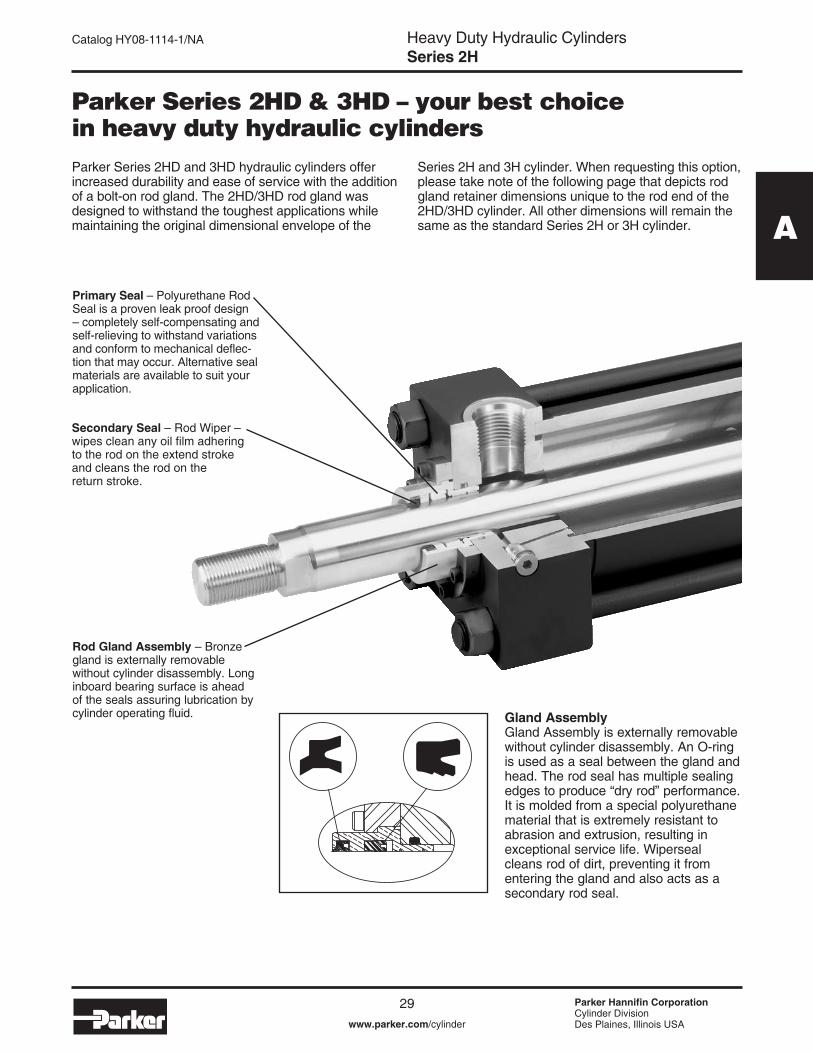
A
Parker Series 2HD & 3HD – your best choice in heavy duty hydraulic cylinders
Primary Seal – Polyurethane Rod Seal is a proven leak proof design – completely self-compensating and self-relieving to withstand variations and conform to mechanical deflec-tion that may occur. Alternative seal materials are available to suit your application.
Secondary Seal – Rod Wiper – wipes clean any oil film adhering to the rod on the extend stroke and cleans the rod on the return stroke.
Rod Gland Assembly – Bronze gland is externally removable without cylinder disassembly. Long inboard bearing surface is ahead of the seals assuring lubrication by cylinder operating fluid.
Parker Series 2HD and 3HD hydraulic cylinders offer increased durability and ease of service with the addition of a bolt-on rod gland. The 2HD/3HD rod gland was designed to withstand the toughest applications while maintaining the original dimensional envelope of the
Series 2H and 3H cylinder. When requesting this option, please take note of the following page that depicts rod gland retainer dimensions unique to the rod end of the 2HD/3HD cylinder. All other dimensions will remain the same as the standard Series 2H or 3H cylinder.
Gland AssemblyGland Assembly is externally removable without cylinder disassembly. An O-ring is used as a seal between the gland and head. The rod seal has multiple sealing edges to produce “dry rod” performance. It is molded from a special polyurethane material that is extremely resistant to abrasion and extrusion, resulting in exceptional service life. Wiperseal cleans rod of dirt, preventing it from entering the gland and also acts as a secondary rod seal.

Heavy Duty Hydraulic CylindersSeries 2H
30 Parker Hannifin CorporationCylinder DivisionDes Plaines, Illinois USAwww.parker.com/cylinder
Catalog HY08-���4-�/NA
2HD / 3HD Rod Gland Dimensional Comparison
B = Bolt-On Gland with Circular RetainerR = Tie Rod Retained Gland� 2H J & JB Mounts have reduced pressure ratings. Refer to J and JB mounts in 2H Section for de-rated operating pressure associated with
the use of the 2HD gland.
Bolt-On Gland Option 2HD & 3HD
Bolt On Rod Gland (B) Tie Rod Retained Gland (R)
RT
KBWF
ØRDØ MMØ B
W
F
Ø MM
Bore Ø
Rod No.
MM Rod
Ø
2HD Rod Gland Retention Bolt On Rod Gland Dimensions
Mounting Style
TC, H, HB, HH, C, F, D, DB, DD, DE,
BB, SB
TB, TD J, JB1 JJ B Ø +.000 -.002
RD Ø
RT KB VF W WF F
�.50� (Std.) 0.625 B R R B �.�24 �.94 0.38 0.�9 0.25 0.63 �.00 0.38
2 �.000 R R R B �.499 2.38 0.38 0.�9 0.50 �.00 �.38 0.38
2.00� (Std.) �.000 B R R B �.499 2.38 0.38 0.�9 0.50 0.75 �.38 0.63
2 �.375 R R R B �.999 2.88 0.38 0.�9 0.63 �.00 �.63 0.63
2.50� (Std.) �.000 B B B B �.499 2.38 0.38 0.�9 0.50 0.75 �.38 0.63
2 �.750 B B B B 2.374 3.47 0.63 0.�9 0.50 �.25 �.88 0.633 �.375 B B R B �.999 2.88 0.38 0.�9 0.63 �.00 �.63 0.63
3.25� (Std.) �.375 B B B B �.999 2.88 0.38 0.�9 0.63 0.88 �.63 0.75
2 2.000 B B B B 2.624 3.72 0.63 0.�9 0.50 �.25 2.00 0.753 �.750 B B B B 2.374 3.47 0.63 0.25 0.50 �.�3 �.88 0.75
4.00� (Std.) �.750 B B B B 2.374 3.47 0.63 0.�9 0.50 �.00 �.88 0.88
2 2.500 B B B B 3.�24 4.25 0.63 0.25 0.63 �.38 2.25 0.883 2.000 B B B B 2.624 3.72 0.63 0.25 0.50 �.�3 2.00 0.88
5.00
� (Std.) 2.000 B B B B 2.624 3.72 0.63 0.25 0.50 �.�3 2.00 0.882 3.500 B B B B 4.249 5.94 0.94 0.25 0.3� �.38 2.25 0.883 2.500 B B B B 3.�24 4.25 0.63 - 0.63 �.38 2.25 0.884 3.000 B B B B 3.749 5.44 0.88 - 0.3� �.38 2.25 0.88
6.00
� (Std.) 2.500 B B B B 3.�24 4.25 0.63 0.25 0.63 �.25 2.25 �.002 4.000 B B B B 4.749 6.3� 0.94 - 0.3� �.25 2.25 �.003 3.000 B B B B 3.749 5.44 0.88 - 0.3� �.25 2.25 �.004 3.500 B B B B 4.249 5.94 0.94 - 0.3� �.25 2.25 �.00
7.00
� (Std.) 3.000 B B B B 3.749 5.44 0.88 - 0.3� - 2.25 �.002 5.000 B B B B 5.749 7.44 0.94 - 0.3� - 2.25 �.003 3.500 B B B B 4.249 5.94 0.94 - 0.3� - 2.25 �.004 4.000 B B B B 4.749 6.3� 0.94 - 0.3� - 2.25 �.005 4.500 B B B B 5.249 6.94 0.94 - 0.3� - 2.25 �.00
8.00
� (Std.) 3.500 B B B B 4.249 5.94 0.94 - 0.3� - 2.25 �.002 5.500 B B B B 6.249 7.94 0.94 - 0.3� - 2.25 �.003 4.000 B B B B 4.749 6.3� 0.94 - 0.3� - 2.25 �.004 4.500 B B B B 5.249 6.94 0.94 - 0.3� - 2.25 �.005 5.000 B B B B 5.749 7.44 0.94 - 0.3� - 2.25 �.00

Heavy Duty Hydraulic CylindersSeries 3H
3� Parker Hannifin CorporationCylinder DivisionDes Plaines, Illinois USAwww.parker.com/cylinder
Catalog HY08-���4-�/NA
B
Heavy Duty Service – Industrial Tie-Rod Constructionn Nominal Pressure – 3000 psin Sixteen Standard Mounting Styles – 7.00" and 8.00" Boren Twelve Standard Mounting Styles – 10.00" through 20.00" Bore
High Pressure Hydraulic Cylinders Series 3H 7.00" through 20.00"
High Pressure Hydraulic Cylinders

Heavy Duty Hydraulic CylindersSeries 3H
32 Parker Hannifin CorporationCylinder DivisionDes Plaines, Illinois USAwww.parker.com/cylinder
Catalog HY08-���4-�/NA
The large bore, high pressure hydraulic cylinder Parker designed to meet your needsParker Series 3H cylinders provide unmatched reliability, performance, and innovative design features that aid in increasing productivity while reducing operating costs.
Parker’s externally removable bolt-on gland assembly makes preventive and routine maintenance quick and easy! In many cases, the cylinder does not have to be removed or disassembled to facilitate service. Our innovative design provides for fast turn around, reduced downtime, and increased productivity.
In addition to our patented removable gland assembly, Series 3H cylinders also include a multitude of
innovative design features such as: anti-extrusion body end seals, floating cushions, hi load piston (standard), and various port and rod end options to meet your application requirements.
Every Series 3H cylinder is individually tested before leaving our plant to assure proper and leak free operation. All Series 3H cylinders come with an �8 month warranty standard.
Design Features

Heavy Duty Hydraulic CylindersSeries 3H
33 Parker Hannifin CorporationCylinder DivisionDes Plaines, Illinois USAwww.parker.com/cylinder
Catalog HY08-���4-�/NA
B
Series 3H Heavy Duty Hydraulic Cylinders
7.00" & 8.00" Bore �0.00" through 20.00" Bore
Specifications, Mounting Styles 34 35
3H Cylinder Model Code & How to Order 36 36
Rod End Styles and Dimensions 38 39
TB, TC and TD Dimensions 40 53
J Mount Dimensions 43 –
JB Mount Dimensions 44 56
JJ Mount Dimensions 45 54, 55
C Mount Dimensions 46 59
F Mount Dimensions 46 –
HH Mount Dimensions 42 57
HB Mount Dimensions 42 58
H Mount Dimensions 4� –
BB Mount Dimensions 47 60
D Mount Dimensions 48 6�
DB Mount Dimensions 49 62
DD Mount Dimensions 50 63
DE Mount Dimensions 5� –
Double Rod End Cylinders 52 64
Section B
Table of Contents

Heavy Duty Hydraulic CylindersSeries 3H
34 Parker Hannifin CorporationCylinder DivisionDes Plaines, Illinois USAwww.parker.com/cylinder
Catalog HY08-���4-�/NA
Standard Specifications• Heavy Duty Service — ANSI/(NFPA) T3.6.7R2 - �996 Specifications and Mounting Dimension Standards • Standard Construction — Square Head – Tie Rod Design• Nominal Pressure — 3000 psi�
• Standard Fluid — Hydraulic Oil• Standard Temperature — -�0°F to +�65°F2
• Piston Rod Diameter — 3.000" through 5.500"
• Mounting Styles — �6 standard styles at various application ratings• Strokes — Available in any practical stroke length• Cushions — Optional at either end or both ends of stroke• Rod Ends — Four Standard Choices — specials to order� If hydraulic operating pressure exceeds 3000 psi, send application data for engineering evaluation and recommendation. See Section E for actual design factors.2 See Section E for higher temperature service.
Specifications / Mountings – 7.00" and 8.00"
Tie Rods Extended Both Ends
Head Square Flange Head Rectangular Cap Rectangular Flange Cap Square Flange
(NFPA ME5)
Style JJ7.00" &
8.00"
(NFPA MF2)
Style H7.00" &
8.00"
(NFPA MF6)
Style HB7.00" &
8.00"
(NFPA MF5)
Style JB7.00" &
8.00"
(NFPA MX3) (NFPA MX2)
Style TC7.00" &
8.00"
(NFPA MX�)
Style TD7.00" &
8.00"
(NFPA MF�)
Cap Rectangular Side Lug Side Tapped
(NFPA MS2)
Style C 7.00" &
8.00"
(NFPA MS4)
Style F 7.00" &
8.00"
(NFPA ME6)
Style HH7.00" &
8.00"
Cap Fixed Clevis
(NFPA MP�)
Style BB 7.00" &
8.00"
(NFPA MT�)
Style D 7.00" &
8.00"
Double Rod Cylinders
Head Trunnion
Style KT Shown
Cap Trunnion Intermediate Fixed Trunnion
(NFPA MT4)
Style DD 7.00" &
8.00"
(NFPA MT2)
Style DB 7.00" &
8.00"
Available Mounting StylesTie Rods Extended Head End
Style TB7.00" &
8.00"
Tie Rods Extended Cap End
�Style DE Mount conforms to NFPA MT4 dimensional standard.NOTE: Series 3H Hydraulic Cylinders fully meet ANSI/(NFPA) T3.6.7R2 - �996 Specifications and Mounting Dimension Standards for Square Head Industrial Fluidpower Cylinders.
Most of the above illustrated mounting styles are available in double rod cylinders.
In line with our policy of continuing product improvement, specifications in this catalog are subject to change.
HD Intermediate Trunnion Mount
(NFPA MT4)
Style DE1 7.00" &
8.00"
Head Rectangular Flange
Style J7.00" &
8.00"

Heavy Duty Hydraulic CylindersSeries 3H
35 Parker Hannifin CorporationCylinder DivisionDes Plaines, Illinois USAwww.parker.com/cylinder
Catalog HY08-���4-�/NA
B
Specifications / Mountings – Large Bore
Standard Specifications• Heavy Duty Service • Standard Construction – Square Head – Tie Rod Design• Nominal Pressure – 3000 psi�
• Standard Fluid – Hydraulic Oil• Standard Temperature – -�0°F to +�65°F2
• Bore Sizes – �0.00" through 20.00" (Larger sizes available)
Tie Rods Extended Both Ends Head Rectangular
Head Square Flange Cap Rectangular Cap Square Flange Side Lug
(NFPA ME6)
Style HH�0.00"-20.00"
(NFPA MF6)
Style HB�0.00"-20.00"
(NFPA MS2)
Style C�0.00"-�4.00"
(NFPA MF5)
Style JB�0.00"-20.00"
(NFPA MX3) (NFPA MX2)
Style TC�0.00"-�4.00"
(NFPA MX�)
Style TD�0.00"-�4.00"
(NFPA ME5)
Style JJ�0.00"-�4.00"
Cap Fixed Clevis Head Trunnion Cap Trunnion
(NFPA MP�)
Style BB �0.00"-20.00"
(NFPA MT�)
Style D �0.00"-�4.00"
(NFPA MT2)
Style DB �0.00"-�4.00"
Intermediate Fixed Trunnion
(NFPA MT4)
Style DD �0.00"-20.00"
Available Mounting StylesTie Rods Extended Head End
Style TB�0.00"-�4.00"
Tie Rods Extended Cap End
• Piston Rod Diameter – 4.500" through �0.000"• Mounting Styles – �2 standard styles at various application ratings• Strokes – Available in any practical stroke length• Cushions – Optional at either end or both ends of stroke • Rod Ends – Three Standard Choices – Specials to Order
� If hydraulic operating pressure exceeds 3000 psi, send application data for engineering evaluation and recommendation. See Section E for actual design factors.2 See Section E for higher temperature service.In line with our policy of continuing product improvement, specifications in this catalog are subject to change.
Double Rod Cylinders
Most of the above illustrated mounting styles are available in double rod cylinders.
Style KC Shown

Heavy Duty Hydraulic CylindersSeries 3H
36 Parker Hannifin CorporationCylinder DivisionDes Plaines, Illinois USAwww.parker.com/cylinder
Catalog HY08-���4-�/NA
3H Model Code
How To Order
8.00
Bore Dia.
Specify bore dia. in inches7.00 8.00 �0.00 �2.00 �4.00 �6.00 �8.00 20.00
Use “C” only if head end cushion is required.
C K F P 3H K T
Double Rod EndCylinder
Use “K” only if a double rod end cylinder is required.�
Cushion Head
Mounting Style
T = Basic, No Mount TB = Tie Rods Ext. Head TC = Tie Rods Ext. CapTD = Tie Rods Ext. Both Ends J = Head Rectangular Flange Limited to 7.00" & 8.00" bore JB = Head Square Flange JJ = Head Rectangular H = Cap Rectangular Flange Limited to 7.00" & 8.00" bore HB = Cap Square Flange HH = Cap Rectangular C = Side Lug2
F = Side Tapped2 Limited to 7.00" & 8.00" bore BB = Cap Fixed Clevis D = Head Trunnion Limited to 7.00" - �4.00" bore DB = Cap Trunnion Limited to 7.00" - �4.00" bore DD = Int. Fixed Trunnion3 DE = Heavy Duty Int. Fixed Trunnion3 Limited to 7.00" & 8.00" bore
Series Designator
Piston Seal
L = Lip Seal Piston K = Hi Load Piston (Std.)F = Low Friction6
C = Ring Packed PistonS = Spring Loaded PTFE piston seals4
Ports
T = SAE Straight Thread O-Ring (Std.) U = NPTF Ports (Dry Seal Pipe Thread) R = BSP Ports Parallel Thread ISO 228)P = SAE Flange Ports (3,000 psi) B = BSPT Ports (Taper Thread) G = Metric Thread Ports Y = Metric Thread Ports per ISO 6�49M = Used only for Manifold Port O-ring Seal. This option is limited to 7.00" and 8.00" bore and applies to C mount only.
Shaded boxes identify required model number fields.
� Available mounting styles for K Type cylinders are located at the end of Section B. When ordering a double rod end cylinder, the piston rod number and piston rod end threads are to be specified for both rod ends. The model number should be created as viewing the primary rod end on the left hand side. Example: K Type Cylinder: 7.00CKTD3HLT�4A28AC�0.000 2 Mounting Styles C and F should have a minimum stroke length equal to or greater than their bore size. 3 Specify XI dimension. 4 Limited to 7.00" and 8.00" bore. 5 In general, the model numbers as read left to right corresponding to the cylinder as viewed from left to right with the primary end at the left. The second or subsequent mountings are mountings called out as they appear in the assembly moving away from the rod end. Except when tie rod extension mountings are part of a combination, all combinations should have a “S” (Special) in the model code and a note in the body of the order clarifying the mounting arrangement. The “P”, as used to define a thrust key is not considered to be a mounting. However it is located at the primary end. 6 Low Friction Piston Seal limited to 7.00" and 8.00" bore.
Mounting Modification
P = Use only if Thrust Key required.4
(Style C or F)M = Use only for Manifold Port O-Ring Seal. Applies to C Mount only.
TB
Any practical mounting style listed.
Combination Mounts5
3H3HD4

Heavy Duty Hydraulic CylindersSeries 3H
37 Parker Hannifin CorporationCylinder DivisionDes Plaines, Illinois USAwww.parker.com/cylinder
Catalog HY08-���4-�/NA
B
How To Order
3H Model Code
J
Common Modification7
J = High Water Content Fluid V = Fluorocarbon Seals W = Water Service X = EPR Seals H = Class 8 Seals8
N = High Temperature Gland9
Special Modification
S 1 4 A C 16.000
Use only if special modifications are required:Oversize PortsPort Position Change Special Seals Stop Tube�0 Stroke Adjusters Tie Rod Supports
Piston Rod Number ��
� 2 3 4 5
Piston Rod End
Select: Style 4 Small MaleStyle 8 Intermediate Male Style 9 Short Female�2 Style 55 Rod End for Flange CouplingStyle 3 Special (Specify)�3
Piston Rod Threads
A = UNF Standard M = Metric�4
Cushion Cap
Used only if cushion required
Stroke�0
Specify in inches
Shaded boxes identify required model number fields.
7 See common modifications Section D for additional options. 8 Class 8 seal option limited to 7.00" & 8.00" bore cylinders. 9 Energized PTFE rod seals & wiperseal are limited to rod sizes of 5.500" and smaller in 7.00" & 8.00" bore size. All other cylinder seals are fluorocarbon. �0 S = Stop Tube. Specify: stop tube length, net stroke and gross stroke. Gross stroke = stop tube length + net stroke. Gross stroke to be placed in the model number field. Example: 2.000 inches long stop tube +�4.000 inches net stroke �6.000 inches gross stroke �� Refer to Rod buckling chart in Section E to assure rod number selected will not buckle under load. �2 Style 9 stroke restrictions may apply. See Style 9 minimum stroke table for details. �3 Provide dimensions for KK, A, W or WF. If otherwise special, furnish dimensioned sketch. �4 See Section D for detailed information regarding standard metric rod end thread sizes.
Bore Ø
RodØ
MinimumStroke
7.00 3.000 �.2503.500 �.5004.000 �.5005.000 3.�25
8.00 3.500 �.5004.000 �.5005.000 2.8755.500 3.625
�0.00 4.500 �.�255.000 �.3755.500 2.0007.000 3.�25
Bore Ø
RodØ
MinimumStroke
�2.00 5.500 �.2507.000 2.3758.000 �.�25
�4.00 7.000 2.0008.000 2.750
�0.000 4.250�6.00 8.000 �.750
9.000 2.500�0.000 3.250
�8.00 9.000 �.500�0.000 2.250
20.00 �0.000 �.250
Style 9 Minimum Stroke Table

Heavy Duty Hydraulic CylindersSeries 3H
38 Parker Hannifin CorporationCylinder DivisionDes Plaines, Illinois USAwww.parker.com/cylinder
Catalog HY08-���4-�/NA
Rod End Dimensions – 7.00" and 8.00" BoreThread Style 8 (NFPA Style IM)
Intermediate MaleThread Style 4 (NFPA Style SM)
Small Male
“Special” Thread Style 3Special thread, extension, rod eye, blank, etc., are also available.
To order, specify “Style 3” and give desired dimensions for KK, A, W or WF. If otherwise special, furnish dimensioned sketch.
� For special WG dimension, specify “Style 3” and give desired dimension for WG. For other changes, place “S” in the model code, and describe rod end with dimensioned sketch. 2 Style 9 stroke restrictions may apply. See Style 9 Minimum Stroke Table on How to Order page for details.3 These piston rod numbers will have 4 spanner wrench holes instead of wrench flats. See rod drawings on next page for dimensions.
Piston Rod Ends – 7.00" and 8.00" Bore
Rod End Dimensions – 7.00" & 8.00" BoreBore
ØRod No.
MM Rod
Ø
Thread Rod Extensions and Pilot DimensionsStyle
8 CC
Style 4 & 9 KK
A B Ø +.000 -.002
D KB NA V RD Ø
RT WF
7.00
� (std.) 3.000 2 3/4-�2 2 �/4-�2 3.50 3.749 2.63 0.250 2.88 0.63 5.25 0.63 2.252 5.000 4 3/4-�2 3 �/2-�2 5.00 5.749 -3 0.000 4.88 0.25 7.25 �.00 2.253 3.500 3 �/4-�2 2 �/2-�2 3.50 4.249 3.00 0.250 3.38 0.63 5.75 0.63 2.254 4.000 3 3/4-�2 3-�2 4.00 4.749 3.38 0.250 3.88 0.50 6.50 0.75 2.255 4.500 4 �/4-�2 3 �/4-�2 4.50 5.249 -3 0.250 4.38 0.50 7.00 0.75 2.25
8.00
� (std.) 3.500 3 �/4-�2 2 �/2-�2 3.50 4.249 3.00 0.250 3.38 0.63 5.75 0.63 2.252 5.500 5 �/4-�2 4-�2 5.50 6.249 -3 0.000 5.38 0.25 8.25 �.00 2.253 4.000 3 3/4-�2 3-�2 4.00 4.749 3.38 0.250 3.88 0.50 6.50 0.75 2.254 4.500 4 �/4-�2 3 �/4-�2 4.50 5.249 -3 0.250 4.38 0.50 7.00 0.75 2.255 5.000 4 3/4-�2 3 �/2-�2 5.00 5.749 -3 0.000 4.88 0.25 7.25 �.00 2.25
Thread Style 92 (NFPA Style SF)Small Female
D WRENCH
KK
WFAV
NAFLATS
ØB ØMM
RTKB
ØRD
CC
WFAV
ØB
NA
ØRD
D WRENCHFLATS
RTKB
ØMM
KK
WFA
V
ØB
NA
ØRD
D WRENCHFLATS
RTKB
ØMM
V
ØMM ØRD
RTKB
.06R
ØAM
AEAD
WG
ØAF
Thread Style 551
MM Rod
Ø
AD AE +.001 -.001
AF Ø
AM Ø
WG1
3.000 2.44 0.874 2.25 2.95 4.883.500 2.69 0.999 2.50 3.45 5.634.000 2.69 0.999 3.00 3.95 5.754.500 3.�9 �.499 3.50 4.45 6.505.000 3.�9 �.499 3.88 4.95 6.635.500 3.94 �.874 4.38 5.45 7.50
Style 55 Rod End

Heavy Duty Hydraulic CylindersSeries 3H
39 Parker Hannifin CorporationCylinder DivisionDes Plaines, Illinois USAwww.parker.com/cylinder
Catalog HY08-���4-�/NA
B
ØB
NA
V
FWFA
KK
.515 DIA.x .75 DEEP4 HOLES
NA
V
FWF
A
KK
ØMM Ø BØRD ØMM ØRD
.515 DIA.x .75 DEEP4 HOLES
Rod End Dimensions – 10.00" - 20.00" Bore
Thread Style 92 (NFPA Style SF)Small Female
Thread Style 4 (NFPA Style SM)Small Male
“Special” Thread Style 3Special thread, extension, rod eye, blank, etc., are also available.
To order, specify “Style 3” and give desired dimensions for KK, A, W or WF. If otherwise special, furnish dimensioned sketch.
Piston Rod Ends – Large Bore
Rod End Dimensions – 10.00" - 20.00" BoreBore
Ø Rod No.
MM Rod
Ø
Thread Style 4 & 9KK
Rod Extensions and Pilot Dimensions
A B Ø +.000 -.005
F NA RD V WF
�0.00
� (std.) 4.500 3 �/4-�2 4.50 5.249 �.94 4.38 8.25 0.25 2.942 7.000 5-�2 7.00 7.999 �.94 6.88 �0.50 0.38 3.503 5.000 3 �/2-�2 5.00 5.749 �.94 4.88 8.88 0.25 3.�94 5.500 4-�2 5.50 6.249 �.94 5.38 9.38 0.25 3.�9
�2.00� (std.) 5.500 4-�2 5.50 6.249 �.94 5.38 9.38 0.25 3.�9
2 8.000 5 3/4-�2 8.00 8.999 �.94 7.88 �2.50 0.38 4.003 7.000 5-�2 7.00 7.999 �.94 6.88 �0.50 0.38 3.50
�4.00� (std.) 7.000 5-�2 7.00 7.999 �.94 6.88 �0.50 0.38 3.50
2 �0.000 7 �/4-�2 �0.00 �0.999 �.94 9.88 �4.50 0.38 4.503 8.000 5 3/4-�2 8.00 8.999 �.94 7.88 �2.50 0.38 4.00
�6.00� 8.000 5 3/4-�2 8.00 8.999 �.94 7.88 �2.50 0.38 4.003 9.000 6 �/2-�2 9.00 9.999 �.94 8.88 �3.50 0.38 4.254 �0.000 7 �/4-�2 �0.00 �0.999 �.94 9.88 �4.50 0.38 4.50
�8.00� 9.000 6 �/2-�2 9.00 9.999 �.94 8.88 �3.50 0.38 4.253 �0.000 7 �/4-�2 �0.00 �0.999 �.94 9.88 �4.50 0.38 4.50
20.00 � �0.000 7 �/4-�2 �0.00 �0.999 �.94 9.88 �4.50 0.38 4.50
ØB
NA
V
FWFA
KK
.515 DIA.x .75 DEEP4 HOLES
NA
V
FWF
A
KK
ØMM Ø BØRD ØMM ØRD
.515 DIA.x .75 DEEP4 HOLES
.06R
ØAM
ØAFAE
AD
WG
V
ØMM ØRDØ B
F
Thread Style 551
Flanged Rod End
� For special WG dimension, specify “Style 3” and give desired dimension for WG. For other changes, place “S” in the model code, and describe rod end with dimensioned sketch.
2 Style 9 stroke restrictions may apply. See Style 9 Minimum Stroke Table on How to Order page for details.
Style 55 Rod EndMM Rod
Ø
AD AE+.001 -.001
AF Ø
AM Ø
WG1
4.500 3.�9 �.499 3.50 4.45 6.505.000 3.�9 �.499 3.88 4.95 6.635.500 3.94 �.874 4.38 5.45 7.507.000 4.06 �.999 5.75 6.95 8.448.000 4.06 �.999 6.50 7.95 8.699.000 4.63 2.374 7.25 8.95 8.75
�0.000 4.63 2.38 8.00 9.95 9.75

Heavy Duty Hydraulic CylindersSeries 3H
40 Parker Hannifin CorporationCylinder DivisionDes Plaines, Illinois USAwww.parker.com/cylinder
Catalog HY08-���4-�/NA
Table 1 – Dimensional and Mounting Data
�NPTF ports are available at no extra charge. 2SAE straight thread ports are standard and are indicated by port number.
Dimensions for TB and TC Mount may be obtained from the above dimensional table.
Mounting Information – 7.00" and 8.00" Bore
G J
DDEE
Y
BBK
ØMM24
R SQ.
AA
3
1
P + STROKE
BB
E SQ.
ZJ + STROKELG + STROKEWF
Tie Rods Extended Both EndsStyle TD(NFPA Style MX�)
Basic Mounting (T) — NFPA MXO — Not shown is no tie rod extended and can be supplied upon request.
Bore Ø
Rod No.
MM Rod
Ø
AA BB DD E EE G J K R WF Y Add StrokeNPTF1 SAE2 LG P ZJ
7.00
� (std.) 3.000 9.3� 4.�3 � �/8-�2 8.50 � �/4 20 2.75 2.75 �.�6 6.58 2.25 3.69 8.50 5.63 �0.752 5.000 9.3� 4.�3 � �/8-�2 8.50 � �/4 20 2.75 2.75 �.�6 6.58 2.25 3.69 8.50 5.63 �0.753 3.500 9.3� 4.�3 � �/8-�2 8.50 � �/4 20 2.75 2.75 �.�6 6.58 2.25 3.69 8.50 5.63 �0.754 4.000 9.3� 4.�3 � �/8-�2 8.50 � �/4 20 2.75 2.75 �.�6 6.58 2.25 3.69 8.50 5.63 �0.755 4.500 9.3� 4.�3 � �/8-�2 8.50 � �/4 20 2.75 2.75 �.�6 6.58 2.25 3.69 8.50 5.63 �0.75
8.00
� (std.) 3.500 �0.6� 4.50 � �/4-�2 9.50 � �/2 24 3.00 3.00 �.28 7.50 2.25 3.8� 9.50 6.38 ��.752 5.500 �0.6� 4.50 � �/4-�2 9.50 � �/2 24 3.00 3.00 �.28 7.50 2.25 3.8� 9.50 6.38 ��.753 4.000 �0.6� 4.50 � �/4-�2 9.50 � �/2 24 3.00 3.00 �.28 7.50 2.25 3.8� 9.50 6.38 ��.754 4.500 �0.6� 4.50 � �/4-�2 9.50 � �/2 24 3.00 3.00 �.28 7.50 2.25 3.8� 9.50 6.38 ��.755 5.000 �0.6� 4.50 � �/4-�2 9.50 � �/2 24 3.00 3.00 �.28 7.50 2.25 3.8� 9.50 6.38 ��.75
Style TB Style TC

Heavy Duty Hydraulic CylindersSeries 3H
4� Parker Hannifin CorporationCylinder DivisionDes Plaines, Illinois USAwww.parker.com/cylinder
Catalog HY08-���4-�/NA
B
Mounting Information – 7.00" and 8.00" Bore
Bore Ø
Rod No.
MM Rod
Ø
AA BB DD E EE G J K R WF Y Add StrokeNPTF1 SAE2 LG P ZJ
7.00
� (std.) 3.000 9.3� 4.�3 � �/8-�2 8.50 � �/4 20 2.75 2.75 �.�6 6.58 2.25 3.69 8.50 5.63 �0.752 5.000 9.3� 4.�3 � �/8-�2 8.50 � �/4 20 2.75 2.75 �.�6 6.58 2.25 3.69 8.50 5.63 �0.753 3.500 9.3� 4.�3 � �/8-�2 8.50 � �/4 20 2.75 2.75 �.�6 6.58 2.25 3.69 8.50 5.63 �0.754 4.000 9.3� 4.�3 � �/8-�2 8.50 � �/4 20 2.75 2.75 �.�6 6.58 2.25 3.69 8.50 5.63 �0.755 4.500 9.3� 4.�3 � �/8-�2 8.50 � �/4 20 2.75 2.75 �.�6 6.58 2.25 3.69 8.50 5.63 �0.75
8.00
� (std.) 3.500 �0.6� 4.50 � �/4-�2 9.50 � �/2 24 3.00 3.00 �.28 7.50 2.25 3.8� 9.50 6.38 ��.752 5.500 �0.6� 4.50 � �/4-�2 9.50 � �/2 24 3.00 3.00 �.28 7.50 2.25 3.8� 9.50 6.38 ��.753 4.000 �0.6� 4.50 � �/4-�2 9.50 � �/2 24 3.00 3.00 �.28 7.50 2.25 3.8� 9.50 6.38 ��.754 4.500 �0.6� 4.50 � �/4-�2 9.50 � �/2 24 3.00 3.00 �.28 7.50 2.25 3.8� 9.50 6.38 ��.755 5.000 �0.6� 4.50 � �/4-�2 9.50 � �/2 24 3.00 3.00 �.28 7.50 2.25 3.8� 9.50 6.38 ��.75
Cap Rectangular Flange MountingStyle H(NFPA Style MF2)
42 E
ETF
GK J 3
1
P + STROKEZF + STROKE
EE
Y
UF
FØFB (X4)
ØMM
XF + STROKELG + STROKE
R
WF
�NPTF ports are available at no extra charge. 2SAE straight thread ports are standard and are indicated by port number.
Table 1 – Dimensional and Mounting Data
Table 2 – Maximum Operating Pressure - 3H & 3HD
Bore Ø
Rod No.
MM Rod Ø
E EE F FB Ø
G J K R TF UF WF Y Add StrokeNPTF1 SAE2 LG P XF ZF
7.00
� (std.) 3.000 8.50 � �/4 20 �.00 �.�9 2.75 2.75 �.�6 6.58 �0.63 �2.63 2.25 3.69 8.50 5.63 �0.75 ��.752 5.000 8.50 � �/4 20 �.00 �.�9 2.75 2.75 �.�6 6.58 �0.63 �2.63 2.25 3.69 8.50 5.63 �0.75 ��.753 3.500 8.50 � �/4 20 �.00 �.�9 2.75 2.75 �.�6 6.58 �0.63 �2.63 2.25 3.69 8.50 5.63 �0.75 ��.754 4.000 8.50 � �/4 20 �.00 �.�9 2.75 2.75 �.�6 6.58 �0.63 �2.63 2.25 3.69 8.50 5.63 �0.75 ��.755 4.500 8.50 � �/4 20 �.00 �.�9 2.75 2.75 �.�6 6.58 �0.63 �2.63 2.25 3.69 8.50 5.63 �0.75 ��.75
8.00
� (std.) 3.500 9.50 � �/2 24 �.00 �.3� 3.00 3.00 �.28 7.50 ��.8� �4.00 2.25 3.8� 9.50 6.38 ��.75 �2.752 5.500 9.50 � �/2 24 �.00 �.3� 3.00 3.00 �.28 7.50 ��.8� �4.00 2.25 3.8� 9.50 6.38 ��.75 �2.753 4.000 9.50 � �/2 24 �.00 �.3� 3.00 3.00 �.28 7.50 ��.8� �4.00 2.25 3.8� 9.50 6.38 ��.75 �2.754 4.500 9.50 � �/2 24 �.00 �.3� 3.00 3.00 �.28 7.50 ��.8� �4.00 2.25 3.8� 9.50 6.38 ��.75 �2.755 5.000 9.50 � �/2 24 �.00 �.3� 3.00 3.00 �.28 7.50 ��.8� �4.00 2.25 3.8� 9.50 6.38 ��.75 �2.75
Bore Ø
Max. psi Pull3
Rod Code1 2 3 4 5
7.00 2000 3000 2000 2500 28008.00 �700 2500 �700 �800 2200
3Maximum pressure rating – pull application.

Heavy Duty Hydraulic CylindersSeries 3H
42 Parker Hannifin CorporationCylinder DivisionDes Plaines, Illinois USAwww.parker.com/cylinder
Catalog HY08-���4-�/NAMounting Information – 7.00" and 8.00" Bore
Cap Square Flange MountingStyle HB(NFPA Style MF6)
42 TF
E SQ.
R
G
K
J 3
1
P + STROKEZF + STROKE
EE
UF SQ.
F ØFB (X8)
ØMM
YXF + STROKE
LG + STROKE
R
TF
WF
Bore Ø
Rod No.
MM Rod Ø
E EE F FB Ø
G J K R TF UF WF Y Add StrokeNPTF1 SAE2 LG P XF ZF
7.00
� (std.) 3.000 8.50 � �/4 20 �.00 �.�9 2.75 2.75 �.�6 6.58 �0.63 �2.63 2.25 3.69 8.50 5.63 �0.75 ��.752 5.000 8.50 � �/4 20 �.00 �.�9 2.75 2.75 �.�6 6.58 �0.63 �2.63 2.25 3.69 8.50 5.63 �0.75 ��.753 3.500 8.50 � �/4 20 �.00 �.�9 2.75 2.75 �.�6 6.58 �0.63 �2.63 2.25 3.69 8.50 5.63 �0.75 ��.754 4.000 8.50 � �/4 20 �.00 �.�9 2.75 2.75 �.�6 6.58 �0.63 �2.63 2.25 3.69 8.50 5.63 �0.75 ��.755 4.500 8.50 � �/4 20 �.00 �.�9 2.75 2.75 �.�6 6.58 �0.63 �2.63 2.25 3.69 8.50 5.63 �0.75 ��.75
8.00
� (std.) 3.500 9.50 � �/2 24 �.00 �.3� 3.00 3.00 �.28 7.50 ��.8� �4.00 2.25 3.8� 9.50 6.38 ��.75 �2.752 5.500 9.50 � �/2 24 �.00 �.3� 3.00 3.00 �.28 7.50 ��.8� �4.00 2.25 3.8� 9.50 6.38 ��.75 �2.753 4.000 9.50 � �/2 24 �.00 �.3� 3.00 3.00 �.28 7.50 ��.8� �4.00 2.25 3.8� 9.50 6.38 ��.75 �2.754 4.500 9.50 � �/2 24 �.00 �.3� 3.00 3.00 �.28 7.50 ��.8� �4.00 2.25 3.8� 9.50 6.38 ��.75 �2.755 5.000 9.50 � �/2 24 �.00 �.3� 3.00 3.00 �.28 7.50 ��.8� �4.00 2.25 3.8� 9.50 6.38 ��.75 �2.75
�NPTF ports are available at no extra charge. 2SAE straight thread ports are standard and are indicated by port number.
Table 1 – Dimensional and Mounting Data
�NPTF ports are available at no extra charge. 2SAE straight thread ports are standard and are indicated by port number.
Cap Rectangular MountingStyle HH(NFPA Style ME6)
Bore Ø
Rod No
MM Rod Ø
E EE FB Ø
G J K R TF UF WF Y Add StrokeNPTF1 SAE2 LG P XF
7.00
� (std.) 3.000 8.50 � �/4 20 �.�9 2.75 2.75 �.�6 6.58 �0.63 �2.63 2.25 3.69 8.50 5.63 �0.752 5.000 8.50 � �/4 20 �.�9 2.75 2.75 �.�6 6.58 �0.63 �2.63 2.25 3.69 8.50 5.63 �0.753 3.500 8.50 � �/4 20 �.�9 2.75 2.75 �.�6 6.58 �0.63 �2.63 2.25 3.69 8.50 5.63 �0.754 4.000 8.50 � �/4 20 �.�9 2.75 2.75 �.�6 6.58 �0.63 �2.63 2.25 3.69 8.50 5.63 �0.755 4.500 8.50 � �/4 20 �.�9 2.75 2.75 �.�6 6.58 �0.63 �2.63 2.25 3.69 8.50 5.63 �0.75
8.00
� (std.) 3.500 9.50 � �/2 24 �.3� 3.00 3.00 �.28 7.50 ��.8� �4.00 2.25 3.8� 9.50 6.38 ��.752 5.500 9.50 � �/2 24 �.3� 3.00 3.00 �.28 7.50 ��.8� �4.00 2.25 3.8� 9.50 6.38 ��.753 4.000 9.50 � �/2 24 �.3� 3.00 3.00 �.28 7.50 ��.8� �4.00 2.25 3.8� 9.50 6.38 ��.754 4.500 9.50 � �/2 24 �.3� 3.00 3.00 �.28 7.50 ��.8� �4.00 2.25 3.8� 9.50 6.38 ��.755 5.000 9.50 � �/2 24 �.3� 3.00 3.00 �.28 7.50 ��.8� �4.00 2.25 3.8� 9.50 6.38 ��.75
42 R E
ETF
GK
J 3
1
P + STROKE
EE
Y
UF
ØFB (X4)
XF + STROKE
ØMM
LG + STROKEWF
Table 1 – Dimensional and Mounting Data

Heavy Duty Hydraulic CylindersSeries 3H
43 Parker Hannifin CorporationCylinder DivisionDes Plaines, Illinois USAwww.parker.com/cylinder
Catalog HY08-���4-�/NA
B
Mounting Information – 7.00" and 8.00" Bore
Head Rectangular Flange MountingStyle J(NFPA Style MF�)
�NPTF ports are available at no extra charge. 2SAE straight thread ports are standard and are indicated by port number.
Table 1 – Dimensional and Mounting Data
GF
.25 J
P + STROKEZB + STROKE
EE
K
ØMM24E R
ETF
3
UF1
ØFB (X4)
Y
WF
W LB + STROKE
Bore Ø
Rod No.
MM Rod
Ø
E EE F FB Ø
G J K R TF UF W WF Y Add StrokeNPTF1 SAE2 LB P ZB
Max.
7.00
� (std.) 3.000 8.50 � �/4 20 �.00 �.�9 2.75 2.75 �.�6 6.58 �0.63 �2.63 �.25 2.25 3.69 9.50 5.63 �2.3�2 5.000 8.50 � �/4 20 �.00 �.�9 2.75 2.75 �.�6 6.58 �0.63 �2.63 �.25 2.25 3.69 9.50 5.63 �2.3�3 3.500 8.50 � �/4 20 �.00 �.�9 2.75 2.75 �.�6 6.58 �0.63 �2.63 �.25 2.25 3.69 9.50 5.63 �2.3�4 4.000 8.50 � �/4 20 �.00 �.�9 2.75 2.75 �.�6 6.58 �0.63 �2.63 �.25 2.25 3.69 9.50 5.63 �2.3�5 4.500 8.50 � �/4 20 �.00 �.�9 2.75 2.75 �.�6 6.58 �0.63 �2.63 �.25 2.25 3.69 9.50 5.63 �2.3�
8.00
� (std.) 3.500 9.50 � �/2 24 �.00 �.3� 3.00 3.00 �.28 7.50 ��.8� �4.00 �.25 2.25 3.8� �0.50 6.38 �3.562 5.500 9.50 � �/2 24 �.00 �.3� 3.00 3.00 �.28 7.50 ��.8� �4.00 �.25 2.25 3.8� �0.50 6.38 �3.563 4.000 9.50 � �/2 24 �.00 �.3� 3.00 3.00 �.28 7.50 ��.8� �4.00 �.25 2.25 3.8� �0.50 6.38 �3.564 4.500 9.50 � �/2 24 �.00 �.3� 3.00 3.00 �.28 7.50 ��.8� �4.00 �.25 2.25 3.8� �0.50 6.38 �3.565 5.000 9.50 � �/2 24 �.00 �.3� 3.00 3.00 �.28 7.50 ��.8� �4.00 �.25 2.25 3.8� �0.50 6.38 �3.56
Table 2 – Maximum Operating Pressure – 3H
3Maximum pressure rating – push application.
Bore Ø
Max. psi Push3
Rod Code
1 2 3 4 5
7.00 �400 800 �200 ��00 �000
8.00 ��00 800 �000 �000 800
For pressures exceeding those shown use mounting styles JB or JJ.
Bore Ø
Max. psi Push3
Rod Code
1 2 3 4 5
7.00 �000 400 800 400 400
8.00 800 400 700 400 400
Table 3 – Maximum Operating Pressure – 3HD
3Maximum pressure rating – push application.

Heavy Duty Hydraulic CylindersSeries 3H
44 Parker Hannifin CorporationCylinder DivisionDes Plaines, Illinois USAwww.parker.com/cylinder
Catalog HY08-���4-�/NAMounting Information – 7.00" and 8.00" Bore
Head Square Flange MountingStyle JB(NFPA Style MF5)
Table 1 – Dimensional and Mounting Data
4 2R TF
TFR
G.25
F
J
3
1P + STROKE
ZB + STROKE
EE
Y
K
ØFB (X8)
ØMM
LB + STROKEW
WF
E SQ.UF SQ.
�NPTF ports are available at no extra charge. 2SAE straight thread ports are standard and are indicated by port number.
Table 2 – Maximum Operating Pressure – 3HBore
Ø Max. psi Push3
Rod Code
1 2 3 4 5
7.00 3000 2700 3000 3000 3000
8.00 3000 2300 2500 2500 2500
Bore Ø
Rod No.
MM Rod
Ø
E EE F FB Ø
G J K R TF UF W WF Y Add StrokeNPTF1 SAE2 LB P ZB
Max.
7.00
� (std.) 3.000 8.50 � �/4 20 �.00 �.�9 2.75 2.75 �.�6 6.58 �0.63 �2.63 �.25 2.25 3.69 9.50 5.63 �2.3�2 5.000 8.50 � �/4 20 �.00 �.�9 2.75 2.75 �.�6 6.58 �0.63 �2.63 �.25 2.25 3.69 9.50 5.63 �2.3�3 3.500 8.50 � �/4 20 �.00 �.�9 2.75 2.75 �.�6 6.58 �0.63 �2.63 �.25 2.25 3.69 9.50 5.63 �2.3�4 4.000 8.50 � �/4 20 �.00 �.�9 2.75 2.75 �.�6 6.58 �0.63 �2.63 �.25 2.25 3.69 9.50 5.63 �2.3�5 4.500 8.50 � �/4 20 �.00 �.�9 2.75 2.75 �.�6 6.58 �0.63 �2.63 �.25 2.25 3.69 9.50 5.63 �2.3�
8.00
� (std.) 3.500 9.50 � �/2 24 �.00 �.3� 3.00 3.00 �.28 7.50 ��.8� �4.00 �.25 2.25 3.8� �0.50 6.38 �3.562 5.500 9.50 � �/2 24 �.00 �.3� 3.00 3.00 �.28 7.50 ��.8� �4.00 �.25 2.25 3.8� �0.50 6.38 �3.563 4.000 9.50 � �/2 24 �.00 �.3� 3.00 3.00 �.28 7.50 ��.8� �4.00 �.25 2.25 3.8� �0.50 6.38 �3.564 4.500 9.50 � �/2 24 �.00 �.3� 3.00 3.00 �.28 7.50 ��.8� �4.00 �.25 2.25 3.8� �0.50 6.38 �3.565 5.000 9.50 � �/2 24 �.00 �.3� 3.00 3.00 �.28 7.50 ��.8� �4.00 �.25 2.25 3.8� �0.50 6.38 �3.56
3Maximum pressure rating – push application.
Table 3 – Maximum Operating Pressure – 3HD
3Maximum pressure rating – push application.
Bore Ø
Max. psi Push3
Rod Code1 2 3 4 5
7.00 2500 �500 2200 �500 �500
8.00 2000 �400 2000 �400 �400

Heavy Duty Hydraulic CylindersSeries 3H
45 Parker Hannifin CorporationCylinder DivisionDes Plaines, Illinois USAwww.parker.com/cylinder
Catalog HY08-���4-�/NA
B
Mounting Information – 7.00" and 8.00" Bore
Head Rectangular MountingStyle JJ(NFPA Style ME5)
Table 1 – Dimensional and Mounting Data
G J
P + STROKEZB + STROKE
EE
K
ØMM24R E
E
TF
3
UF1
Ø FB (X4)
YLG + STROKEWF
Bore Ø
Rod No.
MM Rod
Ø
E EE FB Ø
G J K R TF UF WF Y Add StrokeNPTF1 SAE2 LG P ZB
Max.
7.00
� (std.) 3.000 8.50 � �/4 20 �.�9 2.75 2.75 �.�6 6.58 �0.63 �2.63 2.25 3.69 8.50 5.63 �2.3�2 5.000 8.50 � �/4 20 �.�9 2.75 2.75 �.�6 6.58 �0.63 �2.63 2.25 3.69 8.50 5.63 �2.3�3 3.500 8.50 � �/4 20 �.�9 2.75 2.75 �.�6 6.58 �0.63 �2.63 2.25 3.69 8.50 5.63 �2.3�4 4.000 8.50 � �/4 20 �.�9 2.75 2.75 �.�6 6.58 �0.63 �2.63 2.25 3.69 8.50 5.63 �2.3�5 4.500 8.50 � �/4 20 �.�9 2.75 2.75 �.�6 6.58 �0.63 �2.63 2.25 3.69 8.50 5.63 �2.3�
8.00
� (std.) 3.500 9.50 � �/2 24 �.3� 3.00 3.00 �.28 7.50 ��.8� �4.00 2.25 3.8� 9.50 6.38 �3.562 5.500 9.50 � �/2 24 �.3� 3.00 3.00 �.28 7.50 ��.8� �4.00 2.25 3.8� 9.50 6.38 �3.563 4.000 9.50 � �/2 24 �.3� 3.00 3.00 �.28 7.50 ��.8� �4.00 2.25 3.8� 9.50 6.38 �3.564 4.500 9.50 � �/2 24 �.3� 3.00 3.00 �.28 7.50 ��.8� �4.00 2.25 3.8� 9.50 6.38 �3.565 5.000 9.50 � �/2 24 �.3� 3.00 3.00 �.28 7.50 ��.8� �4.00 2.25 3.8� 9.50 6.38 �3.56
�NPTF ports are available at no extra charge. 2SAE straight thread ports are standard and are indicated by port number.

Heavy Duty Hydraulic CylindersSeries 3H
46 Parker Hannifin CorporationCylinder DivisionDes Plaines, Illinois USAwww.parker.com/cylinder
Catalog HY08-���4-�/NAMounting Information – 7.00" and 8.00" Bore
Side Lug MountingStyle C(NFPA Style MS2)
Table 1 – Dimensional and Mounting Data
�NPTF ports are available at no extra charge. 2SAE straight thread ports are standard and are indicated by port number.
SU SWXS
P + STROKEZB + STROKE
EE
Y
K
ØMM4
ST E/2
ØSB (X4)
-.005-.010
3
US1
2
G J
SWE SQ.
TS SW
LG + STROKE
SUSWSS + STROKE
WF
SW SW
Side Tapped MountingStyle F(NFPA Style MS4)
XT SN + STROKENT THREAD, ND DEEP4 TAPPED MTG. HOLES
P + STROKEZB + STROKE
EE
Y
K
ØMM24ESQ.
E/2 -.005-.010
TN3
1
G J
LG + STROKEWF
Bore Ø
Rod No.
MM Rod
Ø
E EE G J K ND NT TN WF XT Y Add StrokeNPTF1 SAE2 LG P SN ZB
Max.
7.00
� (std.) 3.000 8.50 � �/4 20 2.75 2.75 �.�6 �.�3 � �/2-6 3.75 2.25 3.8� 3.69 8.50 5.63 5.88 �2.3�2 5.000 8.50 � �/4 20 2.75 2.75 �.�6 �.�3 � �/2-6 3.75 2.25 3.8� 3.69 8.50 5.63 5.88 �2.3�3 3.500 8.50 � �/4 20 2.75 2.75 �.�6 �.�3 � �/2-6 3.75 2.25 3.8� 3.69 8.50 5.63 5.88 �2.3�4 4.000 8.50 � �/4 20 2.75 2.75 �.�6 �.�3 � �/2-6 3.75 2.25 3.8� 3.69 8.50 5.63 5.88 �2.3�5 4.500 8.50 � �/4 20 2.75 2.75 �.�6 �.�3 � �/2-6 3.75 2.25 3.8� 3.69 8.50 5.63 5.88 �2.3�
8.00
� (std.) 3.500 9.50 � �/2 24 3.00 3.00 �.28 �.50 � �/2-6 4.25 2.25 3.94 3.8� 9.50 6.38 6.63 �3.562 5.500 9.50 � �/2 24 3.00 3.00 �.28 �.50 � �/2-6 4.25 2.25 3.94 3.8� 9.50 6.38 6.63 �3.563 4.000 9.50 � �/2 24 3.00 3.00 �.28 �.50 � �/2-6 4.25 2.25 3.94 3.8� 9.50 6.38 6.63 �3.564 4.500 9.50 � �/2 24 3.00 3.00 �.28 �.50 � �/2-6 4.25 2.25 3.94 3.8� 9.50 6.38 6.63 �3.565 5.000 9.50 � �/2 24 3.00 3.00 �.28 �.50 � �/2-6 4.25 2.25 3.94 3.8� 9.50 6.38 6.63 �3.56
Table 1 – Dimensional and Mounting Data
�NPTF ports are available at no extra charge. 2SAE straight thread ports are standard and are indicated by port number.
Bore Ø
Rod No.
MM Rod
Ø
E EE G J K SB Ø
ST SU SW TS US WF XS Y Add StrokeNPTF1 SAE2 LG P SS ZB
Max.
7.00
� (std.) 3.000 8.50 � �/4 20 2.75 2.75 �.�6 �.56 �.75 2.88 �.38 ��.25 �4.00 2.25 3.63 3.69 8.50 5.63 5.75 �2.3�
2 5.000 8.50 � �/4 20 2.75 2.75 �.�6 �.56 �.75 2.88 �.38 ��.25 �4.00 2.25 3.63 3.69 8.50 5.63 5.75 �2.3�
3 3.500 8.50 � �/4 20 2.75 2.75 �.�6 �.56 �.75 2.88 �.38 ��.25 �4.00 2.25 3.63 3.69 8.50 5.63 5.75 �2.3�
4 4.000 8.50 � �/4 20 2.75 2.75 �.�6 �.56 �.75 2.88 �.38 ��.25 �4.00 2.25 3.63 3.69 8.50 5.63 5.75 �2.3�
5 4.500 8.50 � �/4 20 2.75 2.75 �.�6 �.56 �.75 2.88 �.38 ��.25 �4.00 2.25 3.63 3.69 8.50 5.63 5.75 �2.3�
8.00
� (std.) 3.500 9.50 � �/2 24 3.00 3.00 �.28 �.56 �.75 2.88 �.38 �2.25 �5.00 2.25 3.63 3.8� 9.50 6.38 6.75 �3.56
2 5.500 9.50 � �/2 24 3.00 3.00 �.28 �.56 �.75 2.88 �.38 �2.25 �5.00 2.25 3.63 3.8� 9.50 6.38 6.75 �3.56
3 4.000 9.50 � �/2 24 3.00 3.00 �.28 �.56 �.75 2.88 �.38 �2.25 �5.00 2.25 3.63 3.8� 9.50 6.38 6.75 �3.56
4 4.500 9.50 � �/2 24 3.00 3.00 �.28 �.56 �.75 2.88 �.38 �2.25 �5.00 2.25 3.63 3.8� 9.50 6.38 6.75 �3.56
5 5.000 9.50 � �/2 24 3.00 3.00 �.28 �.56 �.75 2.88 �.38 �2.25 �5.00 2.25 3.63 3.8� 9.50 6.38 6.75 �3.56
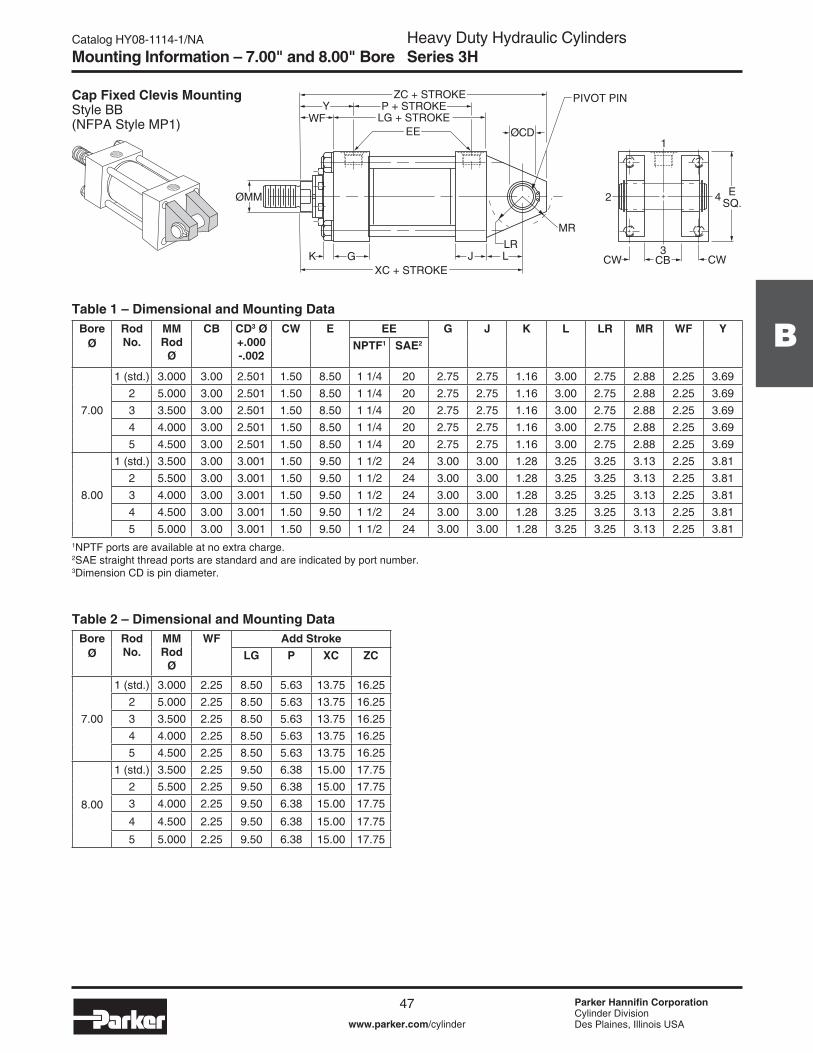
Heavy Duty Hydraulic CylindersSeries 3H
47 Parker Hannifin CorporationCylinder DivisionDes Plaines, Illinois USAwww.parker.com/cylinder
Catalog HY08-���4-�/NA
B
Mounting Information – 7.00" and 8.00" Bore
Cap Fixed Clevis MountingStyle BB(NFPA Style MP�)
Table 1 – Dimensional and Mounting Data
�NPTF ports are available at no extra charge. 2SAE straight thread ports are standard and are indicated by port number.3Dimension CD is pin diameter.
42 ESQ.
CBCW CW3
1
GXC + STROKE
K J
P + STROKEZC + STROKE
EE
Y
ØCD
LLR
MR
PIVOT PIN
ØMM
LG + STROKEWF
Bore Ø
Rod No.
MM Rod
Ø
CB CD3 Ø +.000 -.002
CW E EE G J K L LR MR WF YNPTF1 SAE2
7.00
� (std.) 3.000 3.00 2.50� �.50 8.50 � �/4 20 2.75 2.75 �.�6 3.00 2.75 2.88 2.25 3.692 5.000 3.00 2.50� �.50 8.50 � �/4 20 2.75 2.75 �.�6 3.00 2.75 2.88 2.25 3.693 3.500 3.00 2.50� �.50 8.50 � �/4 20 2.75 2.75 �.�6 3.00 2.75 2.88 2.25 3.694 4.000 3.00 2.50� �.50 8.50 � �/4 20 2.75 2.75 �.�6 3.00 2.75 2.88 2.25 3.695 4.500 3.00 2.50� �.50 8.50 � �/4 20 2.75 2.75 �.�6 3.00 2.75 2.88 2.25 3.69
8.00
� (std.) 3.500 3.00 3.00� �.50 9.50 � �/2 24 3.00 3.00 �.28 3.25 3.25 3.�3 2.25 3.8�2 5.500 3.00 3.00� �.50 9.50 � �/2 24 3.00 3.00 �.28 3.25 3.25 3.�3 2.25 3.8�3 4.000 3.00 3.00� �.50 9.50 � �/2 24 3.00 3.00 �.28 3.25 3.25 3.�3 2.25 3.8�4 4.500 3.00 3.00� �.50 9.50 � �/2 24 3.00 3.00 �.28 3.25 3.25 3.�3 2.25 3.8�5 5.000 3.00 3.00� �.50 9.50 � �/2 24 3.00 3.00 �.28 3.25 3.25 3.�3 2.25 3.8�
Table 2 – Dimensional and Mounting DataBore
ØRod No.
MM Rod
Ø
WF Add StrokeLG P XC ZC
7.00
� (std.) 3.000 2.25 8.50 5.63 �3.75 �6.252 5.000 2.25 8.50 5.63 �3.75 �6.253 3.500 2.25 8.50 5.63 �3.75 �6.254 4.000 2.25 8.50 5.63 �3.75 �6.255 4.500 2.25 8.50 5.63 �3.75 �6.25
8.00
� (std.) 3.500 2.25 9.50 6.38 �5.00 �7.752 5.500 2.25 9.50 6.38 �5.00 �7.753 4.000 2.25 9.50 6.38 �5.00 �7.75
4 4.500 2.25 9.50 6.38 �5.00 �7.75
5 5.000 2.25 9.50 6.38 �5.00 �7.75

Heavy Duty Hydraulic CylindersSeries 3H
48 Parker Hannifin CorporationCylinder DivisionDes Plaines, Illinois USAwww.parker.com/cylinder
Catalog HY08-���4-�/NAMounting Information – 7.00" and 8.00" Bore
Head Trunnion MountingStyle D(NFPA Style MT�)
Table 1 – Dimensional and Mounting Data
�NPTF ports are available at no extra charge. 2SAE straight thread ports are standard and are indicated by port number.
24ESQ. ØTD
TL TL KJ3
LG + STROKEP + STROKE
ZB + STROKE
EE
YUT1
XGG
ØMM
WF
.125R MAX.
Bore Ø
Rod No.
MM Rod
Ø
E EE G J K TD Ø +.000 -.002
TL UT WF Y XGNPTF1 SAE2
7.00
� (std.) 3.000 8.50 � �/4 20 2.75 2.75 �.�6 2.500 2.50 �3.50 2.25 3.69 3.632 5.000 8.50 � �/4 20 2.75 2.75 �.�6 2.500 2.50 �3.50 2.25 3.69 3.633 3.500 8.50 � �/4 20 2.75 2.75 �.�6 2.500 2.50 �3.50 2.25 3.69 3.634 4.000 8.50 � �/4 20 2.75 2.75 �.�6 2.500 2.50 �3.50 2.25 3.69 3.635 4.500 8.50 � �/4 20 2.75 2.75 �.�6 2.500 2.50 �3.50 2.25 3.69 3.63
8.00
� (std.) 3.500 9.50 � �/2 24 3.00 3.00 �.28 3.000 3.00 �5.50 2.25 3.8� 3.752 5.500 9.50 � �/2 24 3.00 3.00 �.28 3.000 3.00 �5.50 2.25 3.8� 3.753 4.000 9.50 � �/2 24 3.00 3.00 �.28 3.000 3.00 �5.50 2.25 3.8� 3.754 4.500 9.50 � �/2 24 3.00 3.00 �.28 3.000 3.00 �5.50 2.25 3.8� 3.755 5.000 9.50 � �/2 24 3.00 3.00 �.28 3.000 3.00 �5.50 2.25 3.8� 3.75
Table 2 – Dimensional and Mounting DataBore
ØRod No.
MM Rod
Ø
Add StrokeLG P ZB
Max.
7.00
� (std.) 3.000 8.50 5.63 �2.3�2 5.000 8.50 5.63 �2.3�3 3.500 8.50 5.63 �2.3�4 4.000 8.50 5.63 �2.3�5 4.500 8.50 5.63 �2.3�
8.00
� (std.) 3.500 9.50 6.38 �3.562 5.500 9.50 6.38 �3.563 4.000 9.50 6.38 �3.564 4.500 9.50 6.38 �3.565 5.000 9.50 6.38 �3.56

Heavy Duty Hydraulic CylindersSeries 3H
49 Parker Hannifin CorporationCylinder DivisionDes Plaines, Illinois USAwww.parker.com/cylinder
Catalog HY08-���4-�/NA
B
Mounting Information – 7.00" and 8.00" Bore
Cap Trunnion MountingStyle DB(NFPA Style MT2)
Table 1 – Dimensional and Mounting Data
�NPTF ports are available at no extra charge. 2SAE straight thread ports are standard and are indicated by port number.
Table 2 – Dimensional and Mounting Data
24ESQ.
ØTD
TL K3
P + STROKEZB + STROKE
EE
YUT
ØMM
1
XJ + STROKEG JTL
LG + STROKEWF
.125R MAX.
Bore Ø
Rod No.
MM Rod
Ø
E EE G J K TD Ø +.000 -.002
TL UT WF YNPTF1 SAE2
7.00
� (std.) 3.000 8.50 � �/4 20 2.75 2.75 �.�6 2.500 2.50 �3.50 2.25 3.692 5.000 8.50 � �/4 20 2.75 2.75 �.�6 2.500 2.50 �3.50 2.25 3.693 3.500 8.50 � �/4 20 2.75 2.75 �.�6 2.500 2.50 �3.50 2.25 3.694 4.000 8.50 � �/4 20 2.75 2.75 �.�6 2.500 2.50 �3.50 2.25 3.695 4.500 8.50 � �/4 20 2.75 2.75 �.�6 2.500 2.50 �3.50 2.25 3.69
8.00
� (std.) 3.500 9.50 � �/2 24 3.00 3.00 �.28 3.000 3.00 �5.50 2.25 3.8�2 5.500 9.50 � �/2 24 3.00 3.00 �.28 3.000 3.00 �5.50 2.25 3.8�3 4.000 9.50 � �/2 24 3.00 3.00 �.28 3.000 3.00 �5.50 2.25 3.8�4 4.500 9.50 � �/2 24 3.00 3.00 �.28 3.000 3.00 �5.50 2.25 3.8�5 5.000 9.50 � �/2 24 3.00 3.00 �.28 3.000 3.00 �5.50 2.25 3.8�
Bore Ø
Rod No.
MM Rod
Ø
Add StrokeLG P XJ ZB
Max
7.00
� (std.) 3.000 8.50 5.63 9.38 �2.3�2 5.000 8.50 5.63 9.38 �2.3�3 3.500 8.50 5.63 9.38 �2.3�4 4.000 8.50 5.63 9.38 �2.3�5 4.500 8.50 5.63 9.38 �2.3�
8.00
� (std.) 3.500 9.50 6.38 �0.25 �3.562 5.500 9.50 6.38 �0.25 �3.563 4.000 9.50 6.38 �0.25 �3.564 4.500 9.50 6.38 �0.25 �3.565 5.000 9.50 6.38 �0.25 �3.56

Heavy Duty Hydraulic CylindersSeries 3H
50 Parker Hannifin CorporationCylinder DivisionDes Plaines, Illinois USAwww.parker.com/cylinder
Catalog HY08-���4-�/NAMounting Information – 7.00" and 8.00" Bore
Intermediate Fixed Trunnion MountingStyle DD (NFPA Former Standard Style MT4)
Table 1 – Dimensional and Mounting Data
24ESQ. ØTD
TMTL
G
XI3
KJ
3
P + STROKEZB + STROKE
BDEEUM
ØMMUW
1
TL
LG + STROKEWF
.125R MAX.
Y
Bore Ø
Rod No.
MM Rod
Ø
BD E EE G J K TD Ø +.000 -.002
TL TM UM UW WF Y Min. XI3NPTF1 SAE2
7.00
� (std.) 3.000 3.00 8.50 � �/4 20 2.75 2.75 �.�6 2.500 2.50 9.75 �4.75 ��.50 2.25 3.69 6.562 5.000 3.00 8.50 � �/4 20 2.75 2.75 �.�6 2.500 2.50 9.75 �4.75 ��.50 2.25 3.69 6.563 3.500 3.00 8.50 � �/4 20 2.75 2.75 �.�6 2.500 2.50 9.75 �4.75 ��.50 2.25 3.69 6.564 4.000 3.00 8.50 � �/4 20 2.75 2.75 �.�6 2.500 2.50 9.75 �4.75 ��.50 2.25 3.69 6.565 4.500 3.00 8.50 � �/4 20 2.75 2.75 �.�6 2.500 2.50 9.75 �4.75 ��.50 2.25 3.69 6.56
8.00
� (std.) 3.500 3.50 9.50 � �/2 24 3.00 3.00 �.28 3.000 3.00 ��.00 �7.00 �3.38 2.25 3.8� 7.062 5.500 3.50 9.50 � �/2 24 3.00 3.00 �.28 3.000 3.00 ��.00 �7.00 �3.38 2.25 3.8� 7.063 4.000 3.50 9.50 � �/2 24 3.00 3.00 �.28 3.000 3.00 ��.00 �7.00 �3.38 2.25 3.8� 7.064 4.500 3.50 9.50 � �/2 24 3.00 3.00 �.28 3.000 3.00 ��.00 �7.00 �3.38 2.25 3.8� 7.065 5.000 3.50 9.50 � �/2 24 3.00 3.00 �.28 3.000 3.00 ��.00 �7.00 �3.38 2.25 3.8� 7.06
�NPTF ports are available at no extra charge. 2SAE straight thread ports are standard and are indicated by port number.3Dimension XI to be specified by customer.
Table 2 – Dimensional and Mounting DataBore
ØRod No.
MM Rod
Ø
Style DD Minimum
Stroke
Add StrokeLG P ZB
Max.
7.00
� (std.) 3.000 0.�3 8.50 5.63 �2.3�2 5.000 0.�3 8.50 5.63 �2.3�3 3.500 0.�3 8.50 5.63 �2.3�4 4.000 0.�3 8.50 5.63 �2.3�5 4.500 0.�3 8.50 5.63 �2.3�
8.00
� (std.) 3.500 0.�3 9.50 6.38 �3.562 5.500 0.�3 9.50 6.38 �3.563 4.000 0.�3 9.50 6.38 �3.564 4.500 0.�3 9.50 6.38 �3.565 5.000 0.�3 9.50 6.38 �3.56

Heavy Duty Hydraulic CylindersSeries 3H
5� Parker Hannifin CorporationCylinder DivisionDes Plaines, Illinois USAwww.parker.com/cylinder
Catalog HY08-���4-�/NA
B
Mounting Information – 7.00" and 8.00" Bore
Heavy Duty Intermediate Fixed Trunnion MountingStyle DE(NFPA Current Standard Style MT4)
Table 1 – Dimensional and Mounting Data
�NPTF ports are available at no extra charge. 2SAE straight thread ports are standard and are indicated by port number.3Dimension XI to be specified by customer.
1
2
3
4
BD
ØMM
G J K
XI3
ØTD
E SQ
TMTL TL
UW
P + STROKEYLG + STROKE
ZB + STROKE
EEUM
WF
.125R MAX.
Bore Ø
Rod No.
MM Rod
Ø
BD E EE G J K TD Ø +.000 -.002
TL TM UM UW WF Y Min XI3NPTF1 SAE2
7.00
� (std.) 3.000 4.000 8.50 � �/4 20 2.75 2.75 �.�6 3.500 2.50 9.75 �4.75 ��.38 2.25 3.69 7.062 5.000 4.000 8.50 � �/4 20 2.75 2.75 �.�6 3.500 2.50 9.75 �4.75 ��.38 2.25 3.69 7.063 3.500 4.000 8.50 � �/4 20 2.75 2.75 �.�6 3.500 2.50 9.75 �4.75 ��.38 2.25 3.69 7.064 4.000 4.000 8.50 � �/4 20 2.75 2.75 �.�6 3.500 2.50 9.75 �4.75 ��.38 2.25 3.69 7.065 4.500 4.000 8.50 � �/4 20 2.75 2.75 �.�6 3.500 2.50 9.75 �4.75 ��.38 2.25 3.69 7.06
8.00
� (std.) 3.500 4.500 9.50 � �/2 24 3.00 3.00 �.28 4.000 3.00 ��.00 �7.00 �2.00 2.25 3.8� 7.562 5.500 4.500 9.50 � �/2 24 3.00 3.00 �.28 4.000 3.00 ��.00 �7.00 �2.00 2.25 3.8� 7.563 4.000 4.500 9.50 � �/2 24 3.00 3.00 �.28 4.000 3.00 ��.00 �7.00 �2.00 2.25 3.8� 7.564 4.500 4.500 9.50 � �/2 24 3.00 3.00 �.28 4.000 3.00 ��.00 �7.00 �2.00 2.25 3.8� 7.565 5.000 4.500 9.50 � �/2 24 3.00 3.00 �.28 4.000 3.00 ��.00 �7.00 �2.00 2.25 3.8� 7.56
Table 2 – Dimensional and Mounting DataBore
ØRod No.
MM Rod
Ø
Style DE Minimum
Stroke
Add StrokeLG P ZB
Max.
7.00
� (std.) 3.000 �.�3 8.50 5.63 �2.3�2 5.000 �.�3 8.50 5.63 �2.3�3 3.500 �.�3 8.50 5.63 �2.3�4 4.000 �.�3 8.50 5.63 �2.3�5 4.500 �.�3 8.50 5.63 �2.3�
8.00
� (std.) 3.500 �.�3 9.50 6.38 �3.562 5.500 �.�3 9.50 6.38 �3.563 4.000 �.�3 9.50 6.38 �3.564 4.500 �.�3 9.50 6.38 �3.565 5.000 �.�3 9.50 6.38 �3.56
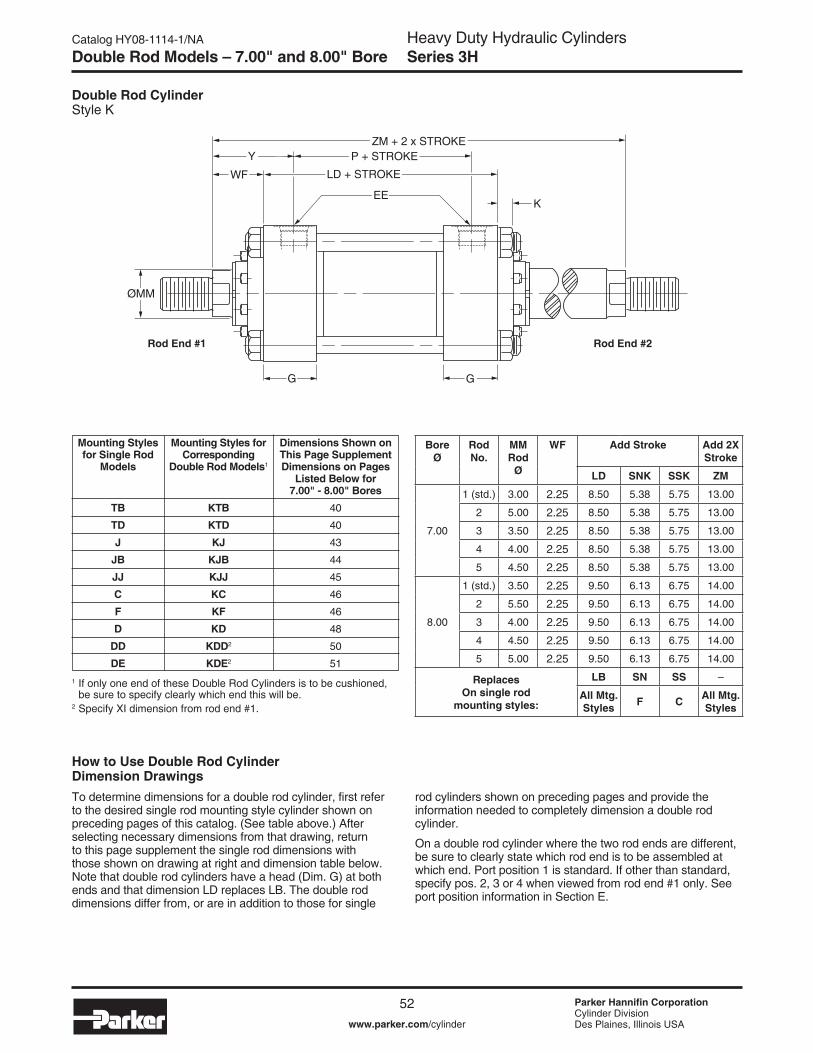
Heavy Duty Hydraulic CylindersSeries 3H
52 Parker Hannifin CorporationCylinder DivisionDes Plaines, Illinois USAwww.parker.com/cylinder
Catalog HY08-���4-�/NA
G G
P + STROKEZM + 2 x STROKE
EE
Y
ØMM
K
LD + STROKEWF
Double Rod CylinderStyle K
Double Rod Models – 7.00" and 8.00" Bore
To determine dimensions for a double rod cylinder, first refer to the desired single rod mounting style cylinder shown on preceding pages of this catalog. (See table above.) After selecting necessary dimensions from that drawing, return to this page supplement the single rod dimensions with those shown on drawing at right and dimension table below. Note that double rod cylinders have a head (Dim. G) at both ends and that dimension LD replaces LB. The double rod dimensions differ from, or are in addition to those for single
rod cylinders shown on preceding pages and provide the information needed to completely dimension a double rod cylinder.
On a double rod cylinder where the two rod ends are different, be sure to clearly state which rod end is to be assembled at which end. Port position � is standard. If other than standard, specify pos. 2, 3 or 4 when viewed from rod end #� only. See port position information in Section E.
Mounting Styles for Single Rod
Models
TBTDJ
JBJJCFD
DDDE
Dimensions Shown on This Page Supplement Dimensions on Pages
Listed Below for 7.00" - 8.00" Bores
40
40
43
44
45
46
46
48
50
5�� If only one end of these Double Rod Cylinders is to be cushioned, be sure to specify clearly which end this will be.2 Specify XI dimension from rod end #�.
Mounting Styles for Corresponding
Double Rod Models�
KTBKTDKJ
KJBKJJKCKFKD
KDD2
KDE2
Bore Ø
Rod No.
MM Rod
Ø
WF Add Stroke Add 2X Stroke
LD SNK SSK ZM
7.00
� (std.) 3.00 2.25 8.50 5.38 5.75 �3.00
2 5.00 2.25 8.50 5.38 5.75 �3.00
3 3.50 2.25 8.50 5.38 5.75 �3.00
4 4.00 2.25 8.50 5.38 5.75 �3.00
5 4.50 2.25 8.50 5.38 5.75 �3.00
8.00
� (std.) 3.50 2.25 9.50 6.�3 6.75 �4.00
2 5.50 2.25 9.50 6.�3 6.75 �4.00
3 4.00 2.25 9.50 6.�3 6.75 �4.00
4 4.50 2.25 9.50 6.�3 6.75 �4.00
5 5.00 2.25 9.50 6.�3 6.75 �4.00
Replaces On single rod
mounting styles:
LB SN SS –
All Mtg. Styles F C All Mtg.
Styles
Rod End #1 Rod End #2
How to Use Double Rod Cylinder Dimension Drawings
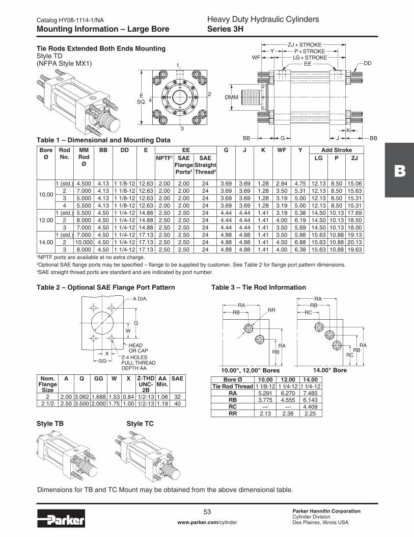
Heavy Duty Hydraulic CylindersSeries 3H
53 Parker Hannifin CorporationCylinder DivisionDes Plaines, Illinois USAwww.parker.com/cylinder
Catalog HY08-���4-�/NA
B
Mounting Information – Large Bore
Tie Rods Extended Both Ends MountingStyle TD(NFPA Style MX�)
Table 1 – Dimensional and Mounting Data
1
4
3
2 MM
DD
+JZ
BBK
+GLEE
BB JG
Y +P
ESQ.
Ø
WF
STROKESTROKESTROKE
Dimensions for TB and TC Mount may be obtained from the above dimensional table.
Style TB Style TC
Bore Ø
Rod No.
MM Rod
Ø
BB DD E EE G J K WF Y Add StrokeNPTF1 SAE
Flange Ports2
SAE Straight Thread3
LG P ZJ
�0.00
� (std.) 4.500 4.�3 � �/8-�2 �2.63 2.00 2.00 24 3.69 3.69 �.28 2.94 4.75 �2.�3 8.50 �5.062 7.000 4.�3 � �/8-�2 �2.63 2.00 2.00 24 3.69 3.69 �.28 3.50 5.3� �2.�3 8.50 �5.633 5.000 4.�3 � �/8-�2 �2.63 2.00 2.00 24 3.69 3.69 �.28 3.�9 5.00 �2.�3 8.50 �5.3�4 5.500 4.�3 � �/8-�2 �2.63 2.00 2.00 24 3.69 3.69 �.28 3.�9 5.00 �2.�3 8.50 �5.3�
�2.00� (std.) 5.500 4.50 � �/4-�2 �4.88 2.50 2.50 24 4.44 4.44 �.4� 3.�9 5.38 �4.50 �0.�3 �7.69
2 8.000 4.50 � �/4-�2 �4.88 2.50 2.50 24 4.44 4.44 �.4� 4.00 6.�9 �4.50 �0.�3 �8.503 7.000 4.50 � �/4-�2 �4.88 2.50 2.50 24 4.44 4.44 �.4� 3.50 5.69 �4.50 �0.�3 �8.00
�4.00� (std.) 7.000 4.50 � �/4-�2 �7.�3 2.50 2.50 24 4.88 4.88 �.4� 3.50 5.88 �5.63 �0.88 �9.�3
2 �0.000 4.50 � �/4-�2 �7.�3 2.50 2.50 24 4.88 4.88 �.4� 4.50 6.88 �5.63 �0.88 20.�33 8.000 4.50 � �/4-�2 �7.�3 2.50 2.50 24 4.88 4.88 �.4� 4.00 6.38 �5.63 �0.88 �9.63
�NPTF ports are available at no extra charge.2Optional SAE flange ports may be specified – flange to be supplied by customer. See Table 2 for flange port pattern dimensions.3SAE straight thread ports are standard and are indicated by port number.
Table 2 – Optional SAE Flange Port Pattern Table 3 – Tie Rod Information
W
HEADOR CAP
Z-4 HOLESFULL THREADDEPTH AA
A DIA.
Q
XGG
RBRA
RBRA
RCRB
RA
RCRB
RA
RR
Nom. Flange
Size2
2 �/2
A
2.002.50
Q
3.0623.500
GG
�.6882.000
W
�.53�.75
X
0.84�.00
AA Min.
�.06�.�9
Z-THDUNC-
2B�/2-�3�/2-�3
SAE
3240
Bore ØTie Rod Thread
RARBRCRR
10.00� �/8-�25.29�3.775
—2.�3
12.00� �/4-�26.2704.555
—2.38
14.00� �/4-�27.4856.�434.4092.25
10.00", 12.00" Bores 14.00" Bore

Heavy Duty Hydraulic CylindersSeries 3H
54 Parker Hannifin CorporationCylinder DivisionDes Plaines, Illinois USAwww.parker.com/cylinder
Catalog HY08-���4-�/NA
Table 1 – Dimensional and Mounting Data
�NPTF ports are available at no extra charge.2Optional SAE flange ports may be specified – flange to be supplied by customer. See Table 2 for flange port pattern dimensions.3SAE straight thread ports are standard and are indicated by port number.
Table 2 – Optional SAE Flange Port Pattern
W
HEADOR CAP
Z-4 HOLESFULL THREADDEPTH AA
A DIA.
Q
XGG
Nom. Flange
Size2
2 �/2
A
2.002.50
Q
3.0623.500
GG
�.6882.000
W
�.53�.75
X
0.84�.00
AA Min.
�.06�.�9
Z-THDUNC-
2B�/2-�3�/2-�3
SAE
3240
Mounting Information – Large Bore
Head Rectangular Mounting Style JJ (�0"-�4" Bore) (NFPA Style ME5)
Bore Ø
Rod No.
MM Rod
Ø
E Ports (EE) FB Ø
G J K R TF UF WF Y Add StrokeNPTF1 SAE
Flange Port2
SAE Straight Thread Port3
LG P ZB Max.
�0.00
� (std.) 4.500 �2.63 2.00 2.00 24 �.8� 3.69 3.69 �.28 9.62 �5.88 �9.00 2.94 4.75 �2.�3 8.50 �6.692 7.000 �2.63 2.00 2.00 24 �.8� 3.69 3.69 �.28 9.62 �5.88 �9.00 3.50 5.3� �2.�3 8.50 �7.253 5.000 �2.63 2.00 2.00 24 �.8� 3.69 3.69 �.28 9.62 �5.88 �9.00 3.�9 5.00 �2.�3 8.50 �6.944 5.500 �2.63 2.00 2.00 24 �.8� 3.69 3.69 �.28 9.62 �5.88 �9.00 3.�9 5.00 �2.�3 8.50 �6.94
�2.00� (std.) 5.500 �4.88 2.50 2.50 24 2.06 4.44 4.44 �.4� ��.45 �8.50 22.00 3.�9 5.38 �4.50 �0.�3 �9.44
2 8.000 �4.88 2.50 2.50 24 2.06 4.44 4.44 �.4� ��.45 �8.50 22.00 4.00 6.�9 �4.50 �0.�3 20.253 7.000 �4.88 2.50 2.50 24 2.06 4.44 4.44 �.4� ��.45 �8.50 22.00 3.50 5.69 �4.50 �0.�3 �9.75
�4.00� (std.) 7.000 �7.�3 2.50 2.50 24 2.3� 4.88 4.88 �.4� �3.26 2�.00 25.00 3.50 5.88 �5.63 �0.88 20.88
2 �0.000 �7.�3 2.50 2.50 24 2.3� 4.88 4.88 �.4� �3.26 2�.00 25.00 4.50 6.88 �5.63 �0.88 2�.883 8.000 �7.�3 2.50 2.50 24 2.3� 4.88 4.88 �.4� �3.26 2�.00 25.00 4.00 6.38 �5.63 �0.88 2�.38
1
2
3
4 MM
EKORTS+GL
KJG
EKORTS+BZEKORTS+PY
B (X4)FE
E
FU
R
FT
Ø
EE
Ø
WF

Heavy Duty Hydraulic CylindersSeries 3H
55 Parker Hannifin CorporationCylinder DivisionDes Plaines, Illinois USAwww.parker.com/cylinder
Catalog HY08-���4-�/NA
B
Mounting Information – Large Bore
Head Rectangular MountingStyle JJ (�6"-20" Bore) (NFPA Style ME5) 1
2
3
4
EE
G KJ
YFU
E
JE JR R
FT
ØMM
WF
ØFB (X8)
ZB + STROKEP + STROKE
LG + STROKE
Table 1 – Dimensional and Mounting Data
�Optional SAE flange ports may be specified – flange to be supplied by customer. See Table 2 for flange port pattern dimensions.2SAE straight thread ports are standard and are indicated by port number.
Table 2 – Optional SAE Flange Port Pattern
W
HEADOR CAP
Z-4 HOLESFULL THREADDEPTH AA
A DIA.
Q
XGG
Nom. Flange
Size3
A
3.00
Q
4.�88
GG
2.438
W
2.09
X
�.22
AA Min.
�.�9
Z-THD UNC-
2B5/8-��
SAE
48
Bore Ø
Rod No.
MM Rod
Ø
E EJ Ports (EE) FB Ø
G J K R RJ TF UF WF Y Add StrokeSAE
Flange Port1
SAE Straight Thread Port2
LG P ZB Max.
�6.00� (std.) 8.000 �9.00 20.00 3.00 24 �.8� 5.88 5.88 �.9� �5.50 8.00 2�.00 24.50 4.00 7.00 �8.�3 �2.�3 24.38
3 9.000 �9.00 20.00 3.00 24 �.8� 5.88 5.88 �.9� �5.50 8.00 2�.00 24.50 4.25 7.25 �8.�3 �2.�3 24.634 �0.000 �9.00 20.00 3.00 24 �.8� 5.88 5.88 �.9� �5.50 8.00 2�.00 24.50 4.50 7.50 �8.�3 �2.�3 24.88
�8.00� (std.) 9.000 22.00 23.00 3.00 24 2.06 6.88 6.88 �.9� �8.00 7.25 24.25 28.25 4.25 7.25 2�.�3 �5.�3 27.63
3 �0.000 22.00 23.00 3.00 24 2.06 6.88 6.88 �.9� �8.00 7.25 24.25 28.25 4.50 7.50 2�.�3 �5.�3 27.8820.00 � (std.) �0.000 24.00 25.00 3.00 24 2.06 7.88 7.88 �.9� 20.00 8.00 26.50 30.50 4.50 7.50 23.63 �7.63 30.38

Heavy Duty Hydraulic CylindersSeries 3H
56 Parker Hannifin CorporationCylinder DivisionDes Plaines, Illinois USAwww.parker.com/cylinder
Catalog HY08-���4-�/NAMounting Information – Large Bore
Head Square Flange Mounting Style JB (NFPA Style MF5)
�NPTF ports are available at no extra charge.2Optional SAE flange ports may be specified – flange to be supplied by customer. See Table 2 for flange port pattern dimensions.3SAE straight thread ports are standard and are indicated by port number.
Table 2 – Optional SAE Flange Port Pattern
W
HEADOR CAP
Z-4 HOLESFULL THREADDEPTH AA
A DIA.
Q
XGG
Nom. Flange
Size2
2 �/23
A
2.002.503.00
Q
3.0623.5004.�88
GG
�.6882.0002.438
W
�.53�.752.09
X
0.84�.00�.22
AA Min.
�.06�.�9�.�9
Z-THD UNC-
2B�/2-�3�/2-�35/8-��
SAE
324048
1
4
3
2MØM
EE
EKORTS+BZ
EKORTS+GL
KJG
Y EKORTS+P
ØEB (X8)E SQ.
X SQ.E
ER
ET
ERET
WF
Table 1 – Dimensional and Mounting DataBore
ØRod No.
MM Rod
Ø
E EB Ø
Ports (EE) EX G J K RE TE WF Y Add StrokeNPTF1 SAE
Flange Port2
SAE Straight Thread Port3
LG P ZB Max.
�0.00
� (std.) 4.500 �2.63 �.3� 2.00 2.00 24 �6.63 3.69 3.69 �.28 9.89 �4.�3 2.94 4.75 �2.�3 8.50 �6.692 7.000 �2.63 �.3� 2.00 2.00 24 �6.63 3.69 3.69 �.28 9.89 �4.�3 3.50 5.3� �2.�3 8.50 �7.253 5.000 �2.63 �.3� 2.00 2.00 24 �6.63 3.69 3.69 �.28 9.89 �4.�3 3.�9 5.00 �2.�3 8.50 �6.944 5.500 �2.63 �.3� 2.00 2.00 24 �6.63 3.69 3.69 �.28 9.89 �4.�3 3.�9 5.00 �2.�3 8.50 �6.94
�2.00� (std.) 5.500 �4.88 �.56 2.50 2.50 24 �9.75 4.44 4.44 �.4� ��.75 �6.79 3.�9 5.38 �4.50 �0.�3 �9.44
2 8.000 �4.88 �.56 2.50 2.50 24 �9.75 4.44 4.44 �.4� ��.75 �6.79 4.00 6.�9 �4.50 �0.�3 20.253 7.000 �4.88 �.56 2.50 2.50 24 �9.75 4.44 4.44 �.4� ��.75 �6.79 3.50 5.69 �4.50 �0.�3 �9.75
�4.00� (std.) 7.000 �7.�3 �.8� 2.50 2.50 24 2�.75 4.88 4.88 �.4� �2.90 �8.43 3.50 5.88 �5.63 �0.88 20.88
2 �0.000 �7.�3 �.8� 2.50 2.50 24 2�.75 4.88 4.88 �.4� �2.90 �8.43 4.50 6.88 �5.63 �0.88 2�.883 8.000 �7.�3 �.8� 2.50 2.50 24 2�.75 4.88 4.88 �.4� �2.90 �8.43 4.00 6.38 �5.63 �0.88 2�.38
�6.00� (std.) 8.000 �9.00 �.8� - 3.00 24 24.50 5.88 5.88 �.9� �5.28 2�.03 4.00 7.00 �8.�3 �2.�3 24.38
3 9.000 �9.00 �.8� - 3.00 24 24.50 5.88 5.88 �.9� �5.28 2�.03 4.25 7.25 �8.�3 �2.�3 24.634 �0.000 �9.00 �.8� - 3.00 24 24.50 5.88 5.88 �.9� �5.28 2�.03 4.50 7.50 �8.�3 �2.�3 24.88
�8.00� (std.) 9.000 22.00 2.06 - 3.00 24 26.50 6.88 6.88 �.9� �6.45 22.65 4.25 7.25 2�.�3 �5.�3 27.63
3 �0.000 22.00 2.06 - 3.00 24 26.50 6.88 6.88 �.9� �6.45 22.65 4.50 7.50 2�.�3 �5.�3 27.8820.00 � (std.) �0.000 24.00 2.06 - 3.00 24 29.00 7.88 7.88 �.9� �8.07 24.87 4.50 7.50 23.63 �7.63 30.38

Heavy Duty Hydraulic CylindersSeries 3H
57 Parker Hannifin CorporationCylinder DivisionDes Plaines, Illinois USAwww.parker.com/cylinder
Catalog HY08-���4-�/NA
B
Mounting Information – Large Bore
Cap Rectangular MountingStyle HH (NFPA Style ME6)
Table 1 – Dimensional and Mounting Data
1
4
3
2MØ
EEEKORTS+GL
EKORTS+FX
GK J
EKORTS+PY
E
B(X4) (10.00-14.00)(X8) (16.00-20.00)
ØFE
(10.00-14.00 only)
FU
EJ(16.00-
20.00 only)JR R
FT
M
WF
Bore Ø
Rod No.
MM Rod
Ø
E Ports (EE) EJ FB Ø
G J K R RJ TF UF WF Y Add StrokeNPTF1 SAE
Flange Port2
SAE Straight Thread Port3
LG P XF
�0.00
� (std.) 4.500 �2.63 2.00 2.00 24 - �.8� 3.69 3.69 �.28 9.62 - �5.88 �9.00 2.94 4.75 �2.�3 8.50 �5.062 7.000 �2.63 2.00 2.00 24 - �.8� 3.69 3.69 �.28 9.62 - �5.88 �9.00 3.50 5.3� �2.�3 8.50 �5.633 5.000 �2.63 2.00 2.00 24 - �.8� 3.69 3.69 �.28 9.62 - �5.88 �9.00 3.�9 5.00 �2.�3 8.50 �5.3�4 5.500 �2.63 2.00 2.00 24 - �.8� 3.69 3.69 �.28 9.62 - �5.88 �9.00 3.�9 5.00 �2.�3 8.50 �5.3�
�2.00� (std.) 5.500 �4.88 2.50 2.50 24 - 2.06 4.44 4.44 �.4� ��.45 - �8.50 22.00 3.�9 5.38 �4.50 �0.�3 �7.69
2 8.000 �4.88 2.50 2.50 24 - 2.06 4.44 4.44 �.4� ��.45 - �8.50 22.00 4.00 6.�9 �4.50 �0.�3 �8.503 7.000 �4.88 2.50 2.50 24 - 2.06 4.44 4.44 �.4� ��.45 - �8.50 22.00 3.50 5.69 �4.50 �0.�3 �8.00
�4.00� (std.) 7.000 �7.�3 2.50 2.50 24 - 2.3� 4.88 4.88 �.4� �3.26 - 2�.00 25.00 3.50 5.88 �5.63 �0.88 �9.�3
2 �0.000 �7.�3 2.50 2.50 24 - 2.3� 4.88 4.88 �.4� �3.26 - 2�.00 25.00 4.50 6.88 �5.63 �0.88 20.�33 8.000 �7.�3 2.50 2.50 24 - 2.3� 4.88 4.88 �.4� �3.26 - 2�.00 25.00 4.00 6.38 �5.63 �0.88 �9.63
�6.00� (std.) 8.000 - - 3.00 24 20.00 �.8� 5.88 5.88 �.9� �5.50 8.00 2�.00 24.50 4.00 7.00 �8.�3 �2.�3 22.�3
3 9.000 - - 3.00 24 20.00 �.8� 5.88 5.88 �.9� �5.50 8.00 2�.00 24.50 4.25 7.25 �8.�3 �2.�3 22.384 �0.000 - - 3.00 24 20.00 �.8� 5.88 5.88 �.9� �5.50 8.00 2�.00 24.50 4.50 7.50 �8.�3 �2.�3 22.63
�8.00� (std.) 9.000 - - 3.00 24 23.00 2.06 6.88 6.88 �.9� �8.00 7.25 24.25 28.25 4.25 7.25 2�.�3 �5.�3 25.38
3 �0.000 - - 3.00 24 23.00 2.06 6.88 6.88 �.9� �8.00 7.25 24.25 28.25 4.50 7.50 2�.�3 �5.�3 25.6320.00 � (std.) �0.000 - - 3.00 24 25.00 2.06 7.88 7.88 �.9� 20.00 8.00 26.50 30.50 4.50 7.50 23.63 �7.63 28.�3
Table 2 – Optional SAE Flange Port Pattern
W
HEADOR CAP
Z-4 HOLESFULL THREADDEPTH AA
A DIA.
Q
XGG
�NPTF ports are available at no extra charge.2Optional SAE flange ports may be specified – flange to be supplied by customer. See Table 2 for flange port pattern dimensions.3SAE straight thread ports are standard and are indicated by port number.
(�0.00-�4.00 Bore)
(�6.00-20.00 Bore)
Nom. Flange
Size2
2 �/23
A
2.002.503.00
Q
3.0623.5004.�88
GG
�.6882.0002.438
W
�.53�.752.09
X
0.84�.00�.22
AA Min.
�.06�.�9�.�9
Z-THDUNC-
2B�/2-�3�/2-�35/8-��
SAE
324048

Heavy Duty Hydraulic CylindersSeries 3H
58 Parker Hannifin CorporationCylinder DivisionDes Plaines, Illinois USAwww.parker.com/cylinder
Catalog HY08-���4-�/NAMounting Information – Large Bore
Cap Square Flange Mounting Style HB (NFPA Style MF6)
�NPTF ports are available at no extra charge.2Optional SAE flange ports may be specified – flange to be supplied by customer. See Table 2 for flange port pattern dimensions.3SAE straight thread ports are standard and are indicated by port number.
Table 2 – Optional SAE Flange Port Pattern
W
HEADOR CAP
Z-4 HOLESFULL THREADDEPTH AA
A DIA.
Q
XGG
Nom. Flange
Size2
2 �/23
A
2.002.503.00
Q
3.0623.5004.�88
GG
�.6882.0002.438
W
�.53�.752.09
X
0.84�.00�.22
AA Min.
�.06�.�9�.�9
Z-THDUNC-
2B�/2-�3�/2-�35/8-��
SAE
324048
Table 1 – Dimensional and Mounting DataBore
ØRod No.
MM Rod
Ø
E EB Ø
Ports (EE) EX G J K RE TE WF Y Add StrokeNPTF1 SAE
Flange Port2
SAE Straight Thread Port3
LG P XF
�0.00
� (std.) 4.500 �2.63 �.3� 2.00 2.00 24 �6.63 3.69 3.69 �.28 9.89 �4.�3 2.94 4.75 �2.�3 8.50 �5.062 7.000 �2.63 �.3� 2.00 2.00 24 �6.63 3.69 3.69 �.28 9.89 �4.�3 3.50 5.3� �2.�3 8.50 �5.633 5.000 �2.63 �.3� 2.00 2.00 24 �6.63 3.69 3.69 �.28 9.89 �4.�3 3.�9 5.00 �2.�3 8.50 �5.3�4 5.500 �2.63 �.3� 2.00 2.00 24 �6.63 3.69 3.69 �.28 9.89 �4.�3 3.�9 5.00 �2.�3 8.50 �5.3�
�2.00� (std.) 5.500 �4.88 �.56 2.50 2.50 24 �9.75 4.44 4.44 �.4� ��.75 �6.79 3.�9 5.38 �4.50 �0.�3 �7.69
2 8.000 �4.88 �.56 2.50 2.50 24 �9.75 4.44 4.44 �.4� ��.75 �6.79 4.00 6.�9 �4.50 �0.�3 �8.503 7.000 �4.88 �.56 2.50 2.50 24 �9.75 4.44 4.44 �.4� ��.75 �6.79 3.50 5.69 �4.50 �0.�3 �8.00
�4.00� (std.) 7.000 �7.�3 �.8� 2.50 2.50 24 2�.75 4.88 4.88 �.4� �2.90 �8.43 3.50 5.88 �5.63 �0.88 �9.�3
2 �0.000 �7.�3 �.8� 2.50 2.50 24 2�.75 4.88 4.88 �.4� �2.90 �8.43 4.50 6.88 �5.63 �0.88 20.�33 8.000 �7.�3 �.8� 2.50 2.50 24 2�.75 4.88 4.88 �.4� �2.90 �8.43 4.00 6.38 �5.63 �0.88 �9.63
�6.00� (std.) 8.000 �9.00 �.8� - 3.00 24 24.50 5.88 5.88 �.9� �5.28 2�.03 4.00 7.00 �8.�3 �2.�3 22.�3
3 9.000 �9.00 �.8� - 3.00 24 24.50 5.88 5.88 �.9� �5.28 2�.03 4.25 7.25 �8.�3 �2.�3 22.384 �0.000 �9.00 �.8� - 3.00 24 24.50 5.88 5.88 �.9� �5.28 2�.03 4.50 7.50 �8.�3 �2.�3 22.63
�8.00� (std.) 9.000 22.00 2.06 - 3.00 24 26.50 6.88 6.88 �.9� �6.45 22.65 4.25 7.25 2�.�3 �5.�3 25.38
3 �0.000 22.00 2.06 - 3.00 24 26.50 6.88 6.88 �.9� �6.45 22.65 4.50 7.50 2�.�3 �5.�3 25.6320.00 � (std.) �0.000 24.00 2.06 - 3.00 24 29.00 7.88 7.88 �.9� �8.07 24.87 4.50 7.50 23.63 �7.63 28.�3
1
4
3
2 MM
EKORTS+GL
K G J
Y EKORTS+P
EE
BE
X SQ.E
E SQ.
ERET
ETER
Ø
WF
EKORTS+XF Ø (X8)

Heavy Duty Hydraulic CylindersSeries 3H
59 Parker Hannifin CorporationCylinder DivisionDes Plaines, Illinois USAwww.parker.com/cylinder
Catalog HY08-���4-�/NA
B
Mounting Information – Large Bore
Side Lugs MountingStyle C(NFPA Style MS2)
Table 1 – Dimensional and Mounting Data
Table 2 – Optional SAE Flange Port Pattern
W
HEADOR CAP
Z-4 HOLESFULL THREADDEPTH AA
A DIA.
Q
XGG
Nom. Flange
Size2
2 �/2
A
2.002.50
Q
3.0623.500
GG
�.6882.000
W
�.53�.75
X
0.84�.00
AA Min.
�.06�.�9
Z-THD UNC-
2B�/2-�3�/2-�3
SAE
3240
�NPTF ports are available at no extra charge.2Optional SAE flange ports may be specified – flange to be supplied by customer. See Table 2 for flange port pattern dimensions.3SAE straight thread ports are standard and are indicated by port number.
1
4
3
2
K
EE
KJG
MM
EKORTS+BZ
EKORTS+GL
US WSWSEKORTS+SS
USSX
Y EKORTS+PSU
B Ø (X4)S
TS
E SQ.
WSWSWS
WSST
E/2 000.+500.-
Ø
WF
Bore Ø
Rod No.
MM Rod
Ø
Add StrokeLG P SS ZB
Max.
�0.00
� (std.) 4.500 �2.�3 8.50 8.88 �6.692 7.000 �2.�3 8.50 8.88 �7.253 5.000 �2.�3 8.50 8.88 �6.944 5.500 �2.�3 8.50 8.88 �6.94
�2.00� (std.) 5.500 �4.50 �0.�3 �0.50 �9.44
2 8.000 �4.50 �0.�3 �0.50 20.253 7.000 �4.50 �0.�3 �0.50 �9.75
�4.00� (std.) 7.000 �5.63 �0.88 ��.�3 20.88
2 �0.000 �5.63 �0.88 ��.�3 2�.883 8.000 �5.63 �0.88 ��.�3 2�.38
Bore Ø
Rod No.
MM Rod
Ø
E Ports (EE) G J K SB Ø
ST SU SW Y TS US WF XSNPTF1 SAE
Flange Port2
SAE Straight Thread Port3
�0.00
� (std.) 4.500 �2.63 2.00 2.00 24 3.69 3.69 �.28 �.563 2.25 3.50 �.63 4.75 �5.88 �9.�3 2.94 4.562 7.000 �2.63 2.00 2.00 24 3.69 3.69 �.28 �.563 2.25 3.50 �.63 5.3� �5.88 �9.�3 3.50 5.�33 5.000 �2.63 2.00 2.00 24 3.69 3.69 �.28 �.563 2.25 3.50 �.63 5.00 �5.88 �9.�3 3.�9 4.8�4 5.500 �2.63 2.00 2.00 24 3.69 3.69 �.28 �.563 2.25 3.50 �.63 5.00 �5.88 �9.�3 3.�9 4.8�
�2.00� (std.) 5.500 �4.88 2.50 2.50 24 4.44 4.44 �.4� �.563 3.00 4.25 2.00 5.38 �8.88 22.88 3.�9 5.�9
2 8.000 �4.88 2.50 2.50 24 4.44 4.44 �.4� �.563 3.00 4.25 2.00 6.�9 �8.88 22.88 4.00 6.003 7.000 �4.88 2.50 2.50 24 4.44 4.44 �.4� �.563 3.00 4.25 2.00 5.69 �8.88 22.88 3.50 5.50
�4.00� (std.) 7.000 �7.�3 2.50 2.50 24 4.88 4.88 �.4� 2.3�3 4.00 4.75 2.25 5.88 2�.63 26.�3 3.50 5.75
2 �0.000 �7.�3 2.50 2.50 24 4.88 4.88 �.4� 2.3�3 4.00 4.75 2.25 6.88 2�.63 26.�3 4.50 6.753 8.000 �7.�3 2.50 2.50 24 4.88 4.88 �.4� 2.3�3 4.00 4.75 2.25 6.38 2�.63 26.�3 4.00 6.25
Table 1 – Dimensional and Mounting Data (cont.)

Heavy Duty Hydraulic CylindersSeries 3H
60 Parker Hannifin CorporationCylinder DivisionDes Plaines, Illinois USAwww.parker.com/cylinder
Catalog HY08-���4-�/NAMounting Information – Large Bore
Cap Fixed Clevis Mounting Style BB (NFPA Style MP�)
�NPTF ports are available at no extra charge.2Optional SAE flange ports may be specified – flange to be supplied by customer. See Table 2 for flange port pattern dimensions.3SAE straight thread ports are standard and are indicated by port number.
Table 2 – Optional SAE Flange Port Pattern
W
HEADOR CAP
Z-4 HOLESFULL THREADDEPTH AA
A DIA.
Q
XGG
Nom. Flange
Size2
2 �/23
A
2.002.503.00
Q
3.0623.5004.�88
GG
�.6882.0002.438
W
�.53�.752.09
X
0.84�.00�.22
AA Min.
�.06�.�9�.�9
Z-THDUNC-
2B�/2-�3�/2-�35/8-��
SAE
324048
Table 1 – Dimensional and Mounting Data
WCCB
WC
ESQ.
NIPTOVIPDEHSINRUF
REDNILYCHTIW
RL
EEEKORTS+GL
RM
G J K
EKORTS+CZEKORTS+PY
LEKORTS+CX
1
4
3
2Ø MM
Ø CD
WF
Bore Ø
Rod No.
MM Rod
Ø
CB CD Ø +.001 -.003
CW E EE Ports G J K L LR MR WF Y Add Stroke
NPTF1 SAE Flange Port2
SAE Straight Thread Port3
LG P XC ZC
�0.00
� (std.) 4.500 4.00 3.500 2.00 �2.63 2.00 2.00 24 3.69 3.69 �.28 4.00 3.38 3.50 2.94 4.75 �2.�3 8.50 �9.06 22.562 7.000 4.00 3.500 2.00 �2.63 2.00 2.00 24 3.69 3.69 �.28 4.00 3.38 3.50 3.50 5.3� �2.�3 8.50 �9.63 23.�33 5.000 4.00 3.500 2.00 �2.63 2.00 2.00 24 3.69 3.69 �.28 4.00 3.38 3.50 3.�9 5.00 �2.�3 8.50 �9.3� 22.8�4 5.500 4.00 3.500 2.00 �2.63 2.00 2.00 24 3.69 3.69 �.28 4.00 3.38 3.50 3.�9 5.00 �2.�3 8.50 �9.3� 22.8�
�2.00� (std.) 5.500 4.50 4.000 2.25 �4.88 2.50 2.50 24 4.44 4.44 �.4� 4.50 3.88 4.00 3.�9 5.38 �4.50 �0.�3 22.�9 26.�9
2 8.000 4.50 4.000 2.25 �4.88 2.50 2.50 24 4.44 4.44 �.4� 4.50 3.88 4.00 4.00 6.�9 �4.50 �0.�3 23.00 27.003 7.000 4.50 4.000 2.25 �4.88 2.50 2.50 24 4.44 4.44 �.4� 4.50 3.88 4.00 3.50 5.69 �4.50 �0.�3 22.50 26.50
�4.00� (std.) 7.000 6.00 5.000 3.00 �7.�3 2.50 2.50 24 4.88 4.88 �.4� 5.75 4.�9 5.00 3.50 5.88 �5.63 �0.88 24.88 29.88
2 �0.000 6.00 5.000 3.00 �7.�3 2.50 2.50 24 4.88 4.88 �.4� 5.75 4.�9 5.00 4.50 6.88 �5.63 �0.88 25.88 30.883 8.000 6.00 5.000 3.00 �7.�3 2.50 2.50 24 4.88 4.88 �.4� 5.75 4.�9 5.00 4.00 6.38 �5.63 �0.88 25.38 30.38
�6.00� (std.) 8.000 7.00 6.000 3.50 �9.00 - 3.00 24 5.88 5.88 �.9� 7.00 6.25 6.00 4.00 7.00 �8.�3 �2.�3 29.�3 35.�3
3 9.000 7.00 6.000 3.50 �9.00 - 3.00 24 5.88 5.88 �.9� 7.00 6.25 6.00 4.25 7.25 �8.�3 �2.�3 29.38 35.384 �0.000 7.00 6.000 3.50 �9.00 - 3.00 24 5.88 5.88 �.9� 7.00 6.25 6.00 4.50 7.50 �8.�3 �2.�3 29.63 35.63
�8.00� (std.) 9.000 8.00 6.500 4.00 22.00 - 3.00 24 6.88 6.88 �.9� 7.63 6.75 6.50 4.25 7.25 2�.�3 �5.�3 33.00 39.50
3 �0.000 8.00 6.500 4.00 22.00 - 3.00 24 6.88 6.88 �.9� 7.63 6.75 6.50 4.50 7.50 2�.�3 �5.�3 33.25 39.7520.00 � (std.) �0.000 9.00 7.500 4.50 24.00 - 3.00 24 7.88 7.88 �.9� 8.75 7.75 7.50 4.50 7.50 23.63 �7.63 36.88 44.38

Heavy Duty Hydraulic CylindersSeries 3H
6� Parker Hannifin CorporationCylinder DivisionDes Plaines, Illinois USAwww.parker.com/cylinder
Catalog HY08-���4-�/NA
B
Mounting Information – Large Bore
Head Trunnion MountingStyle D(NFPA Style MT�)
Table 1 – Dimensional and Mounting Data
Table 2 – Optional SAE Flange Port Pattern
W
HEADOR CAP
Z-4 HOLESFULL THREADDEPTH AA
A DIA.
Q
XGG
Nom. Flange
Size2
2 �/2
A
2.002.50
Q
3.0623.500
GG
�.6882.000
W
�.53�.75
X
0.84�.00
AA Min.
�.06�.�9
Z-THDUNC-
2B�/2-�3�/2-�3
SAE
3240
�NPTF ports are available at no extra charge.2Optional SAE flange ports may be specified – flange to be supplied by customer. See Table 2 for flange port pattern dimensions.3SAE straight thread ports are standard and are indicated by port number.
K
EE
EKORTS+BZ
EKORTS+GL
JG
Y EKORTS+P
GXLTLT
TU1
2
3
4Ø MME
SQ. DØT
WF
.125R MAX.
Bore Ø
Rod No.
MM Rod
Ø
E Ports (EE) G J K TD Ø +.000 -.001
TL UT WF XG Y Add StrokeNPTF1 SAE
Flange Port2
SAE Straight Thread Port3
LG P ZB Max.
�0.00
� (std.) 4.500 �2.63 2.00 2.00 24 3.69 3.69 �.28 3.500 3.50 �9.63 2.94 4.75 4.75 �2.�3 8.50 �6.692 7.000 �2.63 2.00 2.00 24 3.69 3.69 �.28 3.500 3.50 �9.63 3.50 5.3� 5.3� �2.�3 8.50 �7.253 5.000 �2.63 2.00 2.00 24 3.69 3.69 �.28 3.500 3.50 �9.63 3.�9 5.00 5.00 �2.�3 8.50 �6.944 5.500 �2.63 2.00 2.00 24 3.69 3.69 �.28 3.500 3.50 �9.63 3.�9 5.00 5.00 �2.�3 8.50 �6.94
�2.00� (std.) 5.500 �4.88 2.50 2.50 24 4.44 4.44 �.4� 4.000 4.00 22.88 3.�9 5.38 5.38 �4.50 �0.�3 �9.44
2 8.000 �4.88 2.50 2.50 24 4.44 4.44 �.4� 4.000 4.00 22.88 4.00 6.�9 6.�9 �4.50 �0.�3 20.253 7.000 �4.88 2.50 2.50 24 4.44 4.44 �.4� 4.000 4.00 22.88 3.50 5.69 5.69 �4.50 �0.�3 �9.75
�4.00� (std.) 7.000 �7.�3 2.50 2.50 24 4.88 4.88 �.4� 4.500 4.50 26.�3 3.50 5.94 5.88 �5.63 �0.88 20.88
2 �0.000 �7.�3 2.50 2.50 24 4.88 4.88 �.4� 4.500 4.50 26.�3 4.50 6.94 6.88 �5.63 �0.88 2�.883 8.000 �7.�3 2.50 2.50 24 4.88 4.88 �.4� 4.500 4.50 26.�3 4.00 6.44 6.38 �5.63 �0.88 2�.38
Table 3 – Maximum Operating Pressure – D MountBore
Øpsi
�0.00 2800�2.00 2350�4.00 2200

Heavy Duty Hydraulic CylindersSeries 3H
62 Parker Hannifin CorporationCylinder DivisionDes Plaines, Illinois USAwww.parker.com/cylinder
Catalog HY08-���4-�/NAMounting Information – Large Bore
Cap Trunnion Mounting Style DB (NFPA Style MT2)
�NPTF ports are available at no extra charge.2Optional SAE flange ports may be specified – flange to be supplied by customer. See Table 2 for flange port pattern dimensions.3SAE straight thread ports are standard and are indicated by port number.
Table 1 – Dimensional and Mounting Data
K
EE
ZB + STROKEP + STROKELG + STROKE
JG
JX
Y
ESQ.
LTLT
TU1
2
3
4 Ø MMDØT
WF
.125R MAX.
Bore Ø
Rod No.
MM Rod
Ø
E Ports (EE) G J K TD Ø +.000 -.001
TL UT WF Y Add StrokeNPTF1 SAE
Flange Port2
SAE Straight Thread Port3
LG P XJ ZB Max.
�0.00
� (std.) 4.500 �2.63 2.00 2.00 24 3.69 3.69 �.28 3.500 3.50 �9.63 2.94 4.75 �2.�3 8.50 �3.38 �6.692 7.000 �2.63 2.00 2.00 24 3.69 3.69 �.28 3.500 3.50 �9.63 3.50 5.3� �2.�3 8.50 �3.94 �7.253 5.000 �2.63 2.00 2.00 24 3.69 3.69 �.28 3.500 3.50 �9.63 3.�9 5.00 �2.�3 8.50 �3.63 �6.944 5.500 �2.63 2.00 2.00 24 3.69 3.69 �.28 3.500 3.50 �9.63 3.�9 5.00 �2.�3 8.50 �3.63 �6.94
�2.00� (std.) 5.500 �4.88 2.50 2.50 24 4.44 4.44 �.4� 4.000 4.00 22.88 3.�9 5.38 �4.50 �0.�3 �5.50 �9.44
2 8.000 �4.88 2.50 2.50 24 4.44 4.44 �.4� 4.000 4.00 22.88 4.00 6.�9 �4.50 �0.�3 �6.3� 20.253 7.000 �4.88 2.50 2.50 24 4.44 4.44 �.4� 4.000 4.00 22.88 3.50 5.69 �4.50 �0.�3 �5.8� �9.75
�4.00� (std.) 7.000 �7.�3 2.50 2.50 24 4.88 4.88 �.4� 4.500 4.50 26.�3 3.50 5.88 �5.63 �0.88 �6.69 20.88
2 �0.000 �7.�3 2.50 2.50 24 4.88 4.88 �.4� 4.500 4.50 26.�3 4.50 6.88 �5.63 �0.88 �7.69 2�.883 8.000 �7.�3 2.50 2.50 24 4.88 4.88 �.4� 4.500 4.50 26.�3 4.00 6.38 �5.63 �0.88 �7.�9 2�.38
Table 2 – Optional SAE Flange Port Pattern
W
HEADOR CAP
Z-4 HOLESFULL THREADDEPTH AA
A DIA.
Q
XGG
Nom. Flange
Size2
2 �/2
A
2.002.50
Q
3.0623.500
GG
�.6882.000
W
�.53�.75
X
0.84�.00
AA Min.
�.06�.�9
Z-THDUNC-
2B�/2-�3�/2-�3
SAE
3240
Table 3 – Maximum Operating Pressure – DB MountBore
Øpsi
�0.00 2800�2.00 2350�4.00 2200

Heavy Duty Hydraulic CylindersSeries 3H
63 Parker Hannifin CorporationCylinder DivisionDes Plaines, Illinois USAwww.parker.com/cylinder
Catalog HY08-���4-�/NA
B
Mounting Information – Large Bore
Intermediate Fixed Trunnion MountingStyle DD(NFPA Style MT4)
Table 1 – Dimensional and Mounting Data
Table 2 – Optional SAE Flange Port Pattern
W
HEADOR CAP
Z-4 HOLESFULL THREADDEPTH AA
A DIA.
Q
XGG
Nom. Flange
Size2
2 �/23
A
2.002.503.00
Q
3.0623.5004.�88
GG
�.6882.0002.438
W
�.53�.752.09
X
0.84�.00�.22
AA Min.
�.06�.�9�.�9
Z-THDUNC-
2B�/2-�3�/2-�35/8-��
SAE
324048
� NPTF ports are available at no extra charge.2 Optional SAE flange ports may be specified – flange to be supplied by customer. See Table 2 for flange port pattern dimensions.3 SAE straight thread ports are standard and are indicated by port number.
K
EE
EKORTS+ B Z
JG
EKORTS+GL
DBI5X
Y EKORTS+P
4
3
2
1
ESQ.
LTMTLT
YT DØT WU
MU
Ø MM
WF
.125R MAX.
Bore Ø
Rod No.
MM Rod
Ø
E EE Ports BD G J K TD Ø +.000 -.001
TL TM TY UM UW WF Min. XI5
Y Add Stroke
NPTF1 SAE Flge. Port2
SAE Str. Thr. Port3
LG P ZB Max.
�0.00
�(std.) 4.500 �2.63 2.00 2.00 24 4.50 3.69 3.69 �.28 3.500 3.50 �4.00 �3.00 2�.00 �7.50 2.94 9.06 4.75 �2.�3 8.50 �6.692 7.000 �2.63 2.00 2.00 24 4.50 3.69 3.69 �.28 3.500 3.50 �4.00 �3.00 2�.00 �7.50 3.50 9.63 5.3� �2.�3 8.50 �7.253 5.000 �2.63 2.00 2.00 24 4.50 3.69 3.69 �.28 3.500 3.50 �4.00 �3.00 2�.00 �7.50 3.�9 9.3� 5.00 �2.�3 8.50 �6.944 5.500 �2.63 2.00 2.00 24 4.50 3.69 3.69 �.28 3.500 3.50 �4.00 �3.00 2�.00 �7.50 3.�9 9.3� 5.00 �2.�3 8.50 �6.94
�2.00�(std.) 5.500 �4.88 2.50 2.50 24 5.50 4.44 4.44 �.4� 4.000 4.00 �6.50 �5.50 24.50 20.75 3.�9 �0.63 5.38 �4.50 �0.�3 �9.44
2 8.000 �4.88 2.50 2.50 24 5.50 4.44 4.44 �.4� 4.000 4.00 �6.50 �5.50 24.50 20.75 4.00 ��.50 6.�9 �4.50 �0.�3 20.253 7.000 �4.88 2.50 2.50 24 5.50 4.44 4.44 �.4� 4.000 4.00 �6.50 �5.50 24.50 20.75 3.50 �0.94 5.69 �4.50 �0.�3 �9.75
�4.00�(std.) 7.000 �7.�3 2.50 2.50 24 5.50 4.88 4.88 �.4� 4.500 4.50 �9.50 �9.25 28.50 24.75 3.50 ��.44 5.88 �5.63 �0.88 20.88
2 �0.000 �7.�3 2.50 2.50 24 5.50 4.88 4.88 �.4� 4.500 4.50 �9.50 �9.25 28.50 24.75 4.50 �2.44 6.88 �5.63 �0.88 2�.883 8.000 �7.�3 2.50 2.50 24 5.50 4.88 4.88 �.4� 4.500 4.50 �9.50 �9.25 28.50 24.75 4.00 ��.94 6.38 �5.63 �0.88 2�.38
�6.00�(std.) 8.000 �9.00 4 3.00 24 4 5.88 5.88 �.9� 4 4 4 4 4 4 4.00 4 7.00 �8.�3 �2.�3 24.38
3 9.000 �9.00 4 3.00 24 4 5.88 5.88 �.9� 4 4 4 4 4 4 4.25 4 7.25 �8.�3 �2.�3 24.634 �0.000 �9.00 4 3.00 24 4 5.88 5.88 �.9� 4 4 4 4 4 4 4.50 4 7.50 �8.�3 �2.�3 24.88
�8.00�(std.) 9.000 22.00 4 3.00 24 4 6.88 6.88 �.9� 4 4 4 4 4 4 4.25 4 7.25 2�.�3 �5.�3 27.63
3 �0.000 22.00 4 3.00 24 4 6.88 6.88 �.9� 4 4 4 4 4 4 4.50 4 7.50 2�.�3 �5.�3 27.8820.00 �(std.) �0.000 24.00 4 3.00 24 4 7.88 7.88 �.9� 4 4 4 4 4 4 4.50 4 7.50 23.63 �7.63 30.38
4 Consult Factory5 Dimension XI to be specified by customer.
Table 3 – Maximum Operating Pressure – DD MountBore
Øpsi
�0.00 2800�2.00 2350�4.00 2200

Heavy Duty Hydraulic CylindersSeries 3H
64 Parker Hannifin CorporationCylinder DivisionDes Plaines, Illinois USAwww.parker.com/cylinder
Catalog HY08-���4-�/NA
Add 2X Stroke
ZM�8.00�9.�2�8.50�8.5020.8822.502�.5022.6324.6323.6326.�326.6327.�329.6330.�332.63
Rod Code
�234�23�23�34�3�
SUSW SWXS SS + STROKE
LG + STROKE
P + STROKE
ZB + STROKEZM + 2 x STROKE
EEWF
K
ØMM
Y
SUG G
Mounting Styles for Corresponding
Double Rod Models1
KTBKTDKJJKJBKCKD
KDD
Bore Ø
�0.00
�2.00
�4.00
�6.00
�8.00
20.00
Dimension Shown on This Page Supplement Dimensions on Pages
Listed Below5353
54/5556596�63
Mounting Styles for Single Rod
Models
TBTDJJJBCD
DD2
Rod Ø
4.5007.0005.0005.5005.5008.0007.0007.000�0.0008.0008.0009.000�0.0009.000�0.000�0.000
� If only one end of these Double Rod Cylinders is to be cushioned, be sure to specify clearly which end this will be.2 Specify XI dimension from rod end #�.
To obtain dimensioning information on a double rod cylinder, first select the desired mounting style and refer to the corresponding single rod cylinder model shown on the preceding pages. (See table above.) After you have determined all necessary dimensions from that drawing, turn back to this page and supplement those dimensions with additional ones from the drawing above and table at right. These added dimensions differ from, or are in addition to, those shown on the preceding pages and provide the
Rod End #� Rod End #2
Double Rod Models – Large Bore
additional information needed to completely dimension a double rod cylinder model.
On a double rod cylinder where the two rod ends are different, be sure to clearly state which rod end is to be assembled at which end. Port position � is standard. If other than standard, specify pos. 2, 3 or 4 when viewed from rod end #� only. See port position information in Section E.
Double Rod CylinderStyle K
How to Use Double Rod Cylinder Dimension Drawings