CATALOG - Maxitrol© 2013, Maxitrol Company. All Rights Reserved. © 2013 Maxitrol Company. All...
10
CATALOG
-
Upload
phamkhuong -
Category
Documents
-
view
221 -
download
2
Transcript of CATALOG - Maxitrol© 2013, Maxitrol Company. All Rights Reserved. © 2013 Maxitrol Company. All...

CATALOG


© 2013, Maxitrol Company. All Rights Reserved.
DRAFT 09.18.2013
2
Service and installation must be performed by a trained/experienced service technician.
All products used with combustible gas must be installed and used strictly in accordance with the instructions of the Original Equipment Manufacturer (OEM) and with all applicable government codes and regulations, e.g. plumbing, mechanical, and electrical codes and practices. Maxitrol products should be installed and operated in accordance with Maxitrol Safety Warning Instructions.
Maxitrol Company is NOT responsible for any errors or omissions in reliance by anyone of any information set forth in this catalog without additional reference to local requirements and applicable ordinances or codes.
Other worldwide approvals and certifications available upon inquiry.
C US
®
UA.TR.012-13

© 2013, Maxitrol Company. All Rights Reserved.
DRAFT 09.18.2013
50
Pipe Sizes .................................... 3/8” thru 2” threaded connections with NPT or ISO7-1 threads.
Housing Material ........................ All models: aluminum.
Mounting .................................... All models with the exception of 325-7AL210D and 325-9L210E are suitable for multi-positional mounting. 325-7AL210D and 325-9L210E are to be mounted in a horizontal position only. If ball check vent limiting device is installed, mount in an upright position only. NOTE: Line pressure regulators with separate overpressure protection devices are factory preassembled and supplied to the field as a unit. All Maxitrol gas pressure regulators should be installed and operated in accordance with Maxitrol Safety Warning Instructions (see LPROPD_MI_EN.FR).
Certifications ................................ All models: ANSI Z21.80/CSA 6.22 Line Pressure Regulators
Gas Types .................................... Suitable for natural, manufactured, mixed gases, liquefied petroleum gases, and LP gas-air mixtures.
Maximum Inlet Pressure ............. 5 psi (34.5 kPa)
With 12A09, 12A39, or 12A49 Vent Limiter InstalledNatural: 5 psi (34.5 kPa); LP: 2 psi (13.8 kPa)
Minimum Inlet Pressure .............. 1 psi (7 kPa)
Emergency Exposure Limits ......... 65 psi (450 kPa) (inlet side only)
Maximum Individual Load/Capacity ...................................... 325-3L47 (3/8”, 1/2”) (w/OPD 47 attached).................................. 125,000 Btu/h
325-3L48 (1/2”) (w/OPD 48 attached)........................................... 200,000 Btu/h325-5L48 (1/2”) (w/OPD 48 attached)............................................235,000 Btu/h325-5L48 (3/4”) (w/OPD 48 attached)............................................320,000 Btu/h325-5L600 (3/4”) (w/OPD 600 attached)........................................425,000 Btu/h325-5L600 (1”) (w/OPD 600 attached)...........................................465,000 Btu/h325-7AL210D (1 1/4”, 1 1/2”) (w/OPD 210D attached) ..............1,250,000 Btu/h325-9L210E (1 1/2”, 2”) (w/OPD210E attached)..........................2,250,000 Btu/h
Ambient Temperature Ranges ...... -40 to 205°F (-40 to 96°C)
Minimum Regulation ................... Suitable for pilot flow applications. (Circle P) (0.15 CFH NG), (Delta P) (0.50 CFH NG).
Maxitrol’s 325-L Series line pressure regulators with OPDs
are for use on piping systems up to 5 psi. The regulator
reduces pounds pressure to a level within the appliance
or equipment’s operating supply range. The line regulator
is located upstream of equipment already fitted with an
appliance regulator.
NOTE: The 325-9L210E will be available 2Q2014 325-3L47
Specifications
325-L SERIESLever Acting Design with OPDs for 5 psi Piping Systems

© 2013, Maxitrol Company. All Rights Reserved. © 2013 Maxitrol Company. All Rights Reserved.
DRAFT 09.18.2013
51
Model Number Pipe SizeOutlet Pressure
Set Point
Operating Inlet Pressure
1/2 psi (3.4 kPa) 3/4 psi (5.2 kPa) 1 psi (6.9 kPa) 5 psi (34.5 kPa)
325-3L47 3/8” x 3/8”7” w.c. 125 (3.5) 125 (3.5) 125 (3.5) 125 (3.5)
10” w.c. 100 (2.8) 125 (3.5) 125 (3.5) 125 (3.5)
325-3L47 1/2” x 1/2”7” w.c. 125 (3.5) 125 (3.5) 125 (3.5) 125 (3.5)
10” w.c. 105 (2.9) 125 (3.5) 125 (3.5) 125 (3.5)
325-3L48 1/2” x 1/2”7” w.c. 160 (4.5) 200 (5.6) 200 (5.6) 200 (5.6)
10” w.c. 120 (3.4) 200 (5.6) 200 (5.6) 200 (5.6)
325-5L48 1/2” x 1/2”7” w.c. 235 (6.6) 235 (6.6) 235 (6.6) 235 (6.6)
10” w.c. 235 (6.6) 235 (6.6) 235 (6.6) 235 (6.6)
325-5L48 3/4” x 3/4”7” w.c. 320 (9.0) 320 (9.0) 320 (9.0) 320 (9.0)
10” w.c. 245 (6.9) 320 (9.0) 320 (9.0) 320 (9.0)
325-5L600 3/4” x 3/4”7” w.c. 345 (9.6) 425 (11.9) 425 (11.9) 425 (11.9)
10” w.c. 260 (7.3) 425 (11.9) 425 (11.9) 425 (11.9)
325-5L600 1” x 1”7” w.c. 375 (10.5) 465 (13.0) 465 (13.0) 465 (13.0)
10” w.c. 285 (8.0) 465 (13.0) 465 (13.0) 465 (13.0)
325-7AL210D 1 1/4” x 1 1/4”7” w.c. 815 (22.8) 1120 (31.4) 1250 (35.4) 1250 (35.4)
10” w.c. 580 (16.2) 900 (25.2) 1100 (30.8) 1250 (35.4)
325-7AL210D 1 1/2” x 1 1/2”7” w.c. 815 (22.8) 1120 (31.4) 1250 (35.4) 1250 (35.4)
10” w.c. 580 (16.2) 900 (25.2) 1100 (30.8) 1250 (35.4)
325-9L210E 1 1/2” x 1 1/2”7” w.c. 1380 (38.6) 2000 (56.0) 2250 (63.0) 2250 (63.0)
10” w.c. 890 (24.9) 1750 (49.0) 2100 (58.8) 2250 (63.0)
325-9L210E 2” x 2”7” w.c. 1380 (38.6) 2000 (56.0) 2250 (63.0) 2250 (63.0)
10” w.c. 890 (24.9) 1750 (49.0) 2100 (58.8) 2250 (63.0)
NOTE: See pages 58-59 for Regulator Sizing Requirements and Examples.
Imblue Technology™: All models may be ordered with Imblue Technology™. Imblue Technology™ increases corrosion resistance and provides extra protection against the elements for regulators used in outdoor applications. Add suffix letter “B” to model number when ordering.
Capacities expressed in CFH (m3/h) @ 0.64 sp gr gas
Capacities
LINE REGULATORS
C US
®

© 2013, Maxitrol Company. All Rights Reserved.
DRAFT 09.18.2013
52
Model Number Pipe SizePressure Drop
7” w.c. (1.7 kPa) 1/2 psi (3.4 kPa) 3/4 psi (5.2 kPa)
325-3L47 3/8” x 3/8” 130 (3.6) 185 (5.2) 225 (6.3)
325-3L47 1/2” x 1/2” 135 (3.8) 195 (5.4) 235 (6.6)
325-3L48 1/2” x 1/2” 160 (4.5) 225 (6.3) 275 (7.7)
325-5L48 1/2” x 1/2” 315 (8.8) 450 (12.6) 545 (15.4)
325-5L48 3/4” x 3/4” 325 (9.1) 465 (13.0) 565 (16.0)
325-5L600 3/4” x 3/4” 345 (9.6) 490 (13.7) 595 (16.8)
325-5L600 1” x 1” 375 (10.5) 535 (15.0) 650 (18.4)
325-7AL210D 1 1/4” x 1 1/4” 800 (22.7) 1095 (31.0) 1385 (39.2)
325-7AL210D 1 1/2” x 1 1/2” 800 (22.7) 1095 (31.0) 1385 (39.2)
325-9L210E 1 1/2”x 1 1/2” 1360 (38.5) 2113 (59.8) 2557 (72.4)
325-9L210E 2” x 2” 1360 (38.5) 2113 (59.8) 2557 (72.4)
NOTE: See pages 58-59 for Regulator Sizing Requirements and Examples.
Outlet Pressure Range (all models)
Certified Spring ............................. 7” to 11” w.c. (1.7 to 2.7 kPa)
NOTE: Please refer to pages 56-57 for complete Spring Selection Chart.
Pressure Drop expressed in CFH (m3/h) @ 0.64 sp gr gas
Pressure Drop
Spring Range Selection
325-L SERIESLever Acting Design with OPDsfor 5 psi Piping Systems

© 2013, Maxitrol Company. All Rights Reserved. © 2013 Maxitrol Company. All Rights Reserved.
DRAFT 09.18.2013
53
1 Seal Cap
2 Stack
3 Top Housing
4 Rubber Valve
5 Valve Seat
6 Seal Cap Gasket
7 Adjusting Screw
8 Spring
9 Vent Connection
10 Diaphragm
11 Diaphragm Plates
12 Bottom Housing
1
2
3
4
5
9
10
11
6
7
8
12
NOTE: Diagrams are graphical representations only and may differ from actual product.
Lever Acting Design
LINE REGULATORS
© 2013, Maxitrol Company. All Rights Reserved.
DRAFT 09.18.2013
54
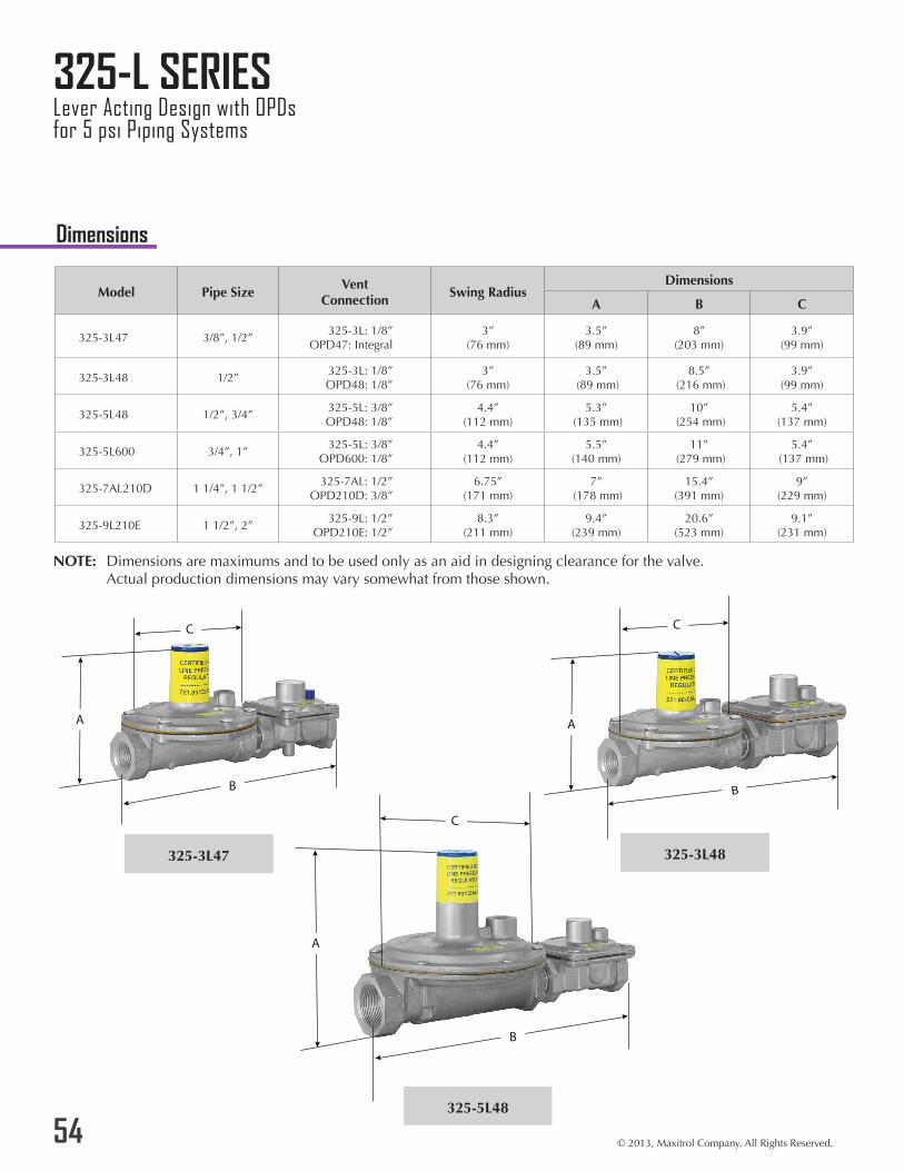
325-3L47 325-3L48
325-5L48
Model Pipe SizeVent
ConnectionSwing Radius
Dimensions
A B C
325-3L47 3/8”, 1/2”325-3L: 1/8”
OPD47: Integral3”
(76 mm)3.5”
(89 mm)8”
(203 mm)3.9”
(99 mm)
325-3L48 1/2”325-3L: 1/8”OPD48: 1/8”
3” (76 mm)
3.5” (89 mm)
8.5” (216 mm)
3.9” (99 mm)
325-5L48 1/2”, 3/4”325-5L: 3/8”OPD48: 1/8”
4.4” (112 mm)
5.3” (135 mm)
10” (254 mm)
5.4” (137 mm)
325-5L600 3/4”, 1”325-5L: 3/8”
OPD600: 1/8”4.4”
(112 mm)5.5”
(140 mm)11”
(279 mm)5.4”
(137 mm)
325-7AL210D 1 1/4”, 1 1/2”325-7AL: 1/2”
OPD210D: 3/8”6.75”
(171 mm)7”
(178 mm)15.4”
(391 mm)9”
(229 mm)
325-9L210E 1 1/2”, 2”325-9L: 1/2”
OPD210E: 1/2”8.3”
(211 mm)9.4”
(239 mm)20.6”
(523 mm)9.1”
(231 mm)
NOTE: Dimensions are maximums and to be used only as an aid in designing clearance for the valve. Actual production dimensions may vary somewhat from those shown.
B
A A
A
Dimensions
325-L SERIESLever Acting Design with OPDsfor 5 psi Piping Systems

© 2013, Maxitrol Company. All Rights Reserved. © 2013 Maxitrol Company. All Rights Reserved.
DRAFT 09.18.2013
55
325-5L600 325-7AL210D
325-9L210E
A
A
LINE REGULATORS
A

Maxitrol Company23555 Telegraph Rd., PO Box 2230Southfield, MI 48037-2230
GPR_MS_EN_11.2013
www.maxitrol.com© 2013 Maxitrol Company
All Rights Reserved