Catalog 2011.pdf - Dubai Pipes Factory Co
40
Contents DPFC Table of Contents Page No. Introduction 1 Technologies Yield Higher Performance at Lower Cost 2 Product Benefits 3 Performance Standards 4 Control Testing & Qualification Testing 5-6 Method of Manufacturing 7 Product Scope - Technical Data 8-11 Pipe Classification Selection 12 Pipe Dimensions 13 Couplings Dimensions 14 Fittings 15 Shipping, Handling and Storage 16-18 General Installation 19-21 Factors Affecting Installation 22 Pipe Joining 23-25 Field Hydrotest - G.R.P. Piping 26-28 Surge Water Hammers 29 Thrust Blocks, Concrete Encasement, Rigid Connections 30-32 Field Adjustments 33-34 Small Diameter Pipes 35-36 Environmental Guide for DPFC Pipe 37-38
Transcript of Catalog 2011.pdf - Dubai Pipes Factory Co

ContentsDPFC
Table of Contents Page No.
Introduction 1
Technologies Yield Higher Performance at Lower Cost 2
Product Benefits 3
Performance Standards 4
Control Testing & Qualification Testing 5-6
Method of Manufacturing 7
Product Scope - Technical Data 8-11
Pipe Classification Selection 12
Pipe Dimensions 13
Couplings Dimensions 14
Fittings 15
Shipping, Handling and Storage 16-18
General Installation 19-21
Factors Affecting Installation 22
Pipe Joining 23-25
Field Hydrotest - G.R.P. Piping 26-28
Surge Water Hammers 29
Thrust Blocks, Concrete Encasement, Rigid Connections 30-32
Field Adjustments 33-34
Small Diameter Pipes 35-36
Environmental Guide for DPFC Pipe 37-38

WHITE

DPFC
Introduction
1
Introduction
Dubai Pipes Factory Co. is a Pipes and Fittings manufacturing firm located in Jebel Ali Industrial Area in Dubai-United Arab Emirates.
The first commissioned production line is made for the manufacturing of Glass Reinforced Plastic Pipes and Fittings upto and including 2400mm diameter. Continuous winding is the process utilized for the GRP pipe production as per the Know How and Technology supplied from Flowtite Technology. All manufacturing and testing equipment are of the latest version in the pipe technology supplied by Flowtite Technology.
The GRP manufacturing, installation procedures, design, testing and qualifications are in accordance to the Know How and Technology supply agreement between Dubai Pipes Factory Co. and Flowtite Technology.
DPFC holds kitemark licenses that confirm the compliance of DPFC GRP pipes with requirement set by international organizations such as ISO, BSI, EN and ASTM.
The second commissioned production line is made for the production of GRP pipes but using the Helical Winding Process.
DPFC is quality committed and ISO 9001:2008 approved. DPFC is also committed to the Environment, and our company is certified for complying with ISO 14001:2004 standard.
DPFC GRP pipe has been tested and approved for the conveyance of portable water. Testing and approval are conducted by Water Regulations Advisory Scheme.
DPFC
2
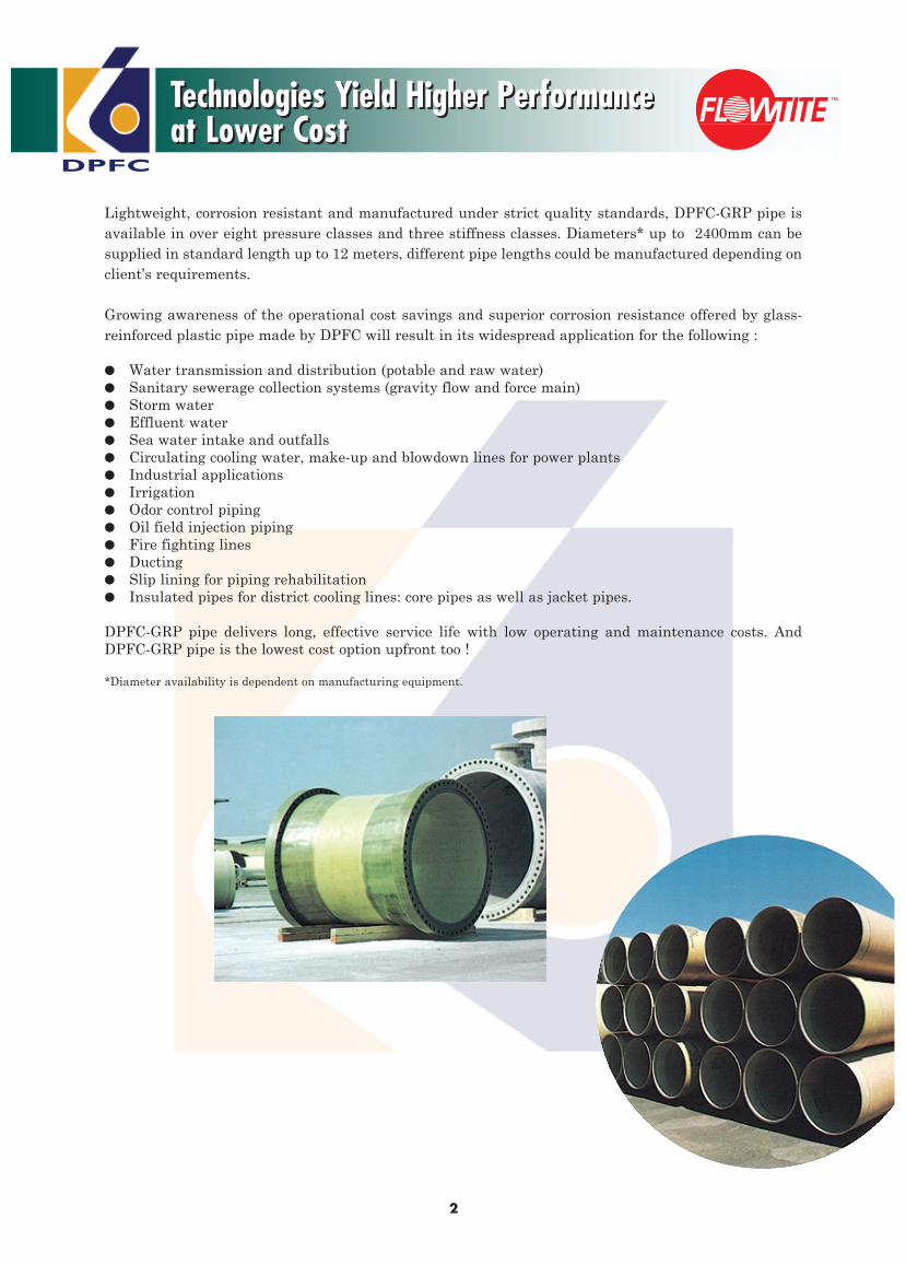
Lightweight, corrosion resistant and manufactured under strict quality standards, DPFC-GRP pipe is available in over eight pressure classes and three stiffness classes. Diameters* up to 2400mm can be supplied in standard length up to 12 meters, different pipe lengths could be manufactured depending on client’s requirements.
Growing awareness of the operational cost savings and superior corrosion resistance offered by glass-reinforced plastic pipe made by DPFC will result in its widespread application for the following :
● Water transmission and distribution (potable and raw water)● Sanitary sewerage collection systems (gravity flow and force main)● Storm water● Effluent water● Sea water intake and outfalls● Circulating cooling water, make-up and blowdown lines for power plants● Industrial applications● Irrigation● Odor control piping● Oil field injection piping● Fire fighting lines● Ducting● Slip lining for piping rehabilitation● Insulated pipes for district cooling lines: core pipes as well as jacket pipes.
DPFC-GRP pipe delivers long, effective service life with low operating and maintenance costs. And DPFC-GRP pipe is the lowest cost option upfront too !
*Diameter availability is dependent on manufacturing equipment.
Technologies Yield Higher Performance at Lower Cost Technologies Yield Higher Performance at Lower Cost

DPFC
Product Benefits
3
DPFC-GRP pipe is bringing a product to the market that can provide low cost, long-term piping solution to the customers around the world. The long list of features and benefits add up to provide the optimum installed and life cycle cost system.
Features
• Corrosion resistant materials.
• Double bell coupling joints manufactured of corrosion resistant glass fiber, and sealed with elastomeric gaskets.
• Light-weight: 1/4th weight of ductile iron and 1/10th of concrete pipe.
• Manufactured in long sections.
• Extremely smooth bore.
• Pipe specifications meet or exceed worldwide standards.
• High technology pipe manufacturing system.
Benefits
• Long, effective service life.• No need for expensive cathodic protection.• No need for costly pipe coating, wrapping,
lining, painting, or use of polyethylene bags.• Low maintenance costs.• Hydraulic characteristics essentially remain
unchanged over time.
• Ease of joining helps reduce installation time.• Tight, efficient joints designed to eliminate
infiltration and exfiltration.• Costly joint diapers are not required.• Allows for flexible alignment, accommodating
changes in line direction with fewer fittings.
• Easy to install. No need for expensive handling equipment.
• Low delivery cost.
• Fewer joints reduce installation time.
• Low friction loss means less pumping energy needed.
• Minimum slime build up can help lower cleaning costs.
• Assures high quality product specification.
• Helps ensure consistent product quality.
Product Benefits
DPFC
Performance Standards
4
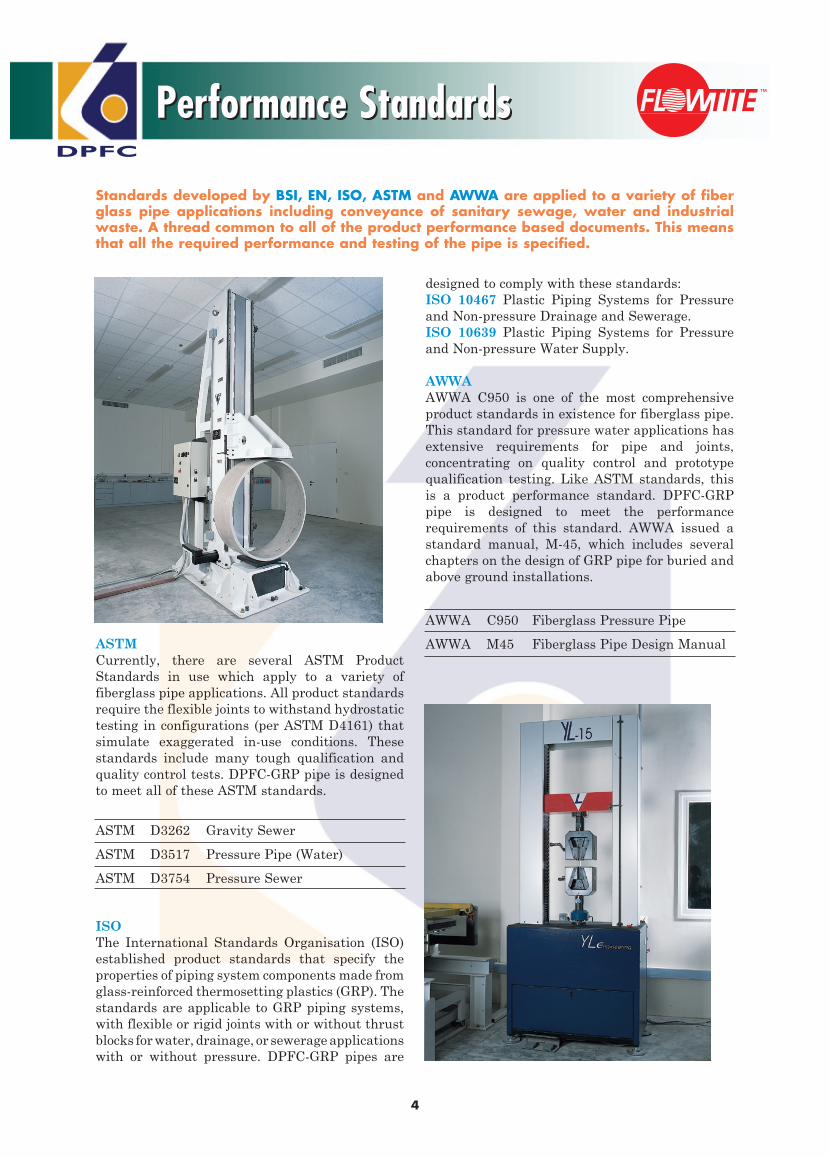
ASTMCurrently, there are several ASTM Product Standards in use which apply to a variety of fiberglass pipe applications. All product standards require the flexible joints to withstand hydrostatic testing in configurations (per ASTM D4161) that simulate exaggerated in-use conditions. These standards include many tough qualification and quality control tests. DPFC-GRP pipe is designed to meet all of these ASTM standards.
ASTM D3262 Gravity Sewer
ASTM D3517 Pressure Pipe (Water)
ASTM D3754 Pressure Sewer
ISOThe International Standards Organisation (ISO) established product standards that specify the properties of piping system components made from glass-reinforced thermosetting plastics (GRP). The standards are applicable to GRP piping systems, with flexible or rigid joints with or without thrust blocks for water, drainage, or sewerage applications with or without pressure. DPFC-GRP pipes are
Standards developed by BSI, EN, ISO, ASTM and AWWA are applied to a variety of fiber glass pipe applications including conveyance of sanitary sewage, water and industrial waste. A thread common to all of the product performance based documents. This means that all the required performance and testing of the pipe is specified.
designed to comply with these standards:ISO 10467 Plastic Piping Systems for Pressure and Non-pressure Drainage and Sewerage. ISO 10639 Plastic Piping Systems for Pressure and Non-pressure Water Supply.
AWWAAWWA C950 is one of the most comprehensive product standards in existence for fiberglass pipe. This standard for pressure water applications has extensive requirements for pipe and joints, concentrating on quality control and prototype qualification testing. Like ASTM standards, this is a product performance standard. DPFC-GRP pipe is designed to meet the performance requirements of this standard. AWWA issued a standard manual, M-45, which includes several chapters on the design of GRP pipe for buried and above ground installations.
AWWA C950 Fiberglass Pressure Pipe
AWWA M45 Fiberglass Pipe Design Manual
Performance Standards

DPFC
5
Raw MaterialsRaw materials are delivered with vendor certification demonstrating their compliance with DPFC quality requirements. In addition, all raw materials are sample tested prior to their use. These tests ensure that the pipe materials comply with the specifications as stated.
Pipe Physical PropertiesThe manufactured pipe’s hoop and axial load strengths are verified on a routine basis. In addition, pipe construction and composition are confirmed.
Finished PipeAll pipes are subjected to the following control checks : ■ Visual inspection■ Barcol hardness■ Wall thickness■ Section Length■ Diameter■ Hydrostatic leak tightness test.
On a sampling basis, the following control checks are performed :■ Pipe stiffness■ Deflection without damage or structural failure■ Axial and circumferential tensile load strength■ Impact resistance
A common element shared by all standards is the need for a pipe manufacturer to demonstrate compliance with the standards minimum performance requirements. In the case of GRP pipe, these minimum performance requirements fall into both short-term and long-term
requirements. The most important of these, and generally specified at the same level of performance in all the previously defined standards is joint, initial ring deflection, long-term ring bending, long-term pressure and strain corrosion capability. DPFC-GRP pipe is rigorously tested to verify conformance to the ASTM D3262, ASTM D3517, AWWA C950, BS EN 1796 and 14364 requirements.
Strain Corrosion TestingA unique and important performance requirement for GRP gravity pipe used in sewer applications is the chemical testing of the pipe in a deflected or strained condition. This strain corrosion testing is carried out in accordance with ASTM D3681, and requires a minimum of 18 ring samples of the pipe to be deflected to various levels and held constant. These strained rings are then exposed at the invert of the interior surface to 1.0N (5% by weight) Sulphuric acid (see Figure 1). This is intended to simulate a buried septic sewer condition. This has been shown to be representative of the worst sewer conditions including those found in the Middle East, where many FLOWTITE pipes (our know how supplier) have been successfully installed.
The time to failure (leakage) for each test sample is measured. The minimum extrapolated failure strain at 50 or 60 years, using a least squares regression analysis of the failure data, must equal the values shown for each stiffness class in Table 1. The value achieved is then relatable to the pipe design to enable prediction of safe installation limitations for GRP pipe used for this type of service.
Stiffness Class Scv. Strain %
SN2500 .49 (t/d)
SN5000 .41 (t/d)
SN10000 .34 (t/d)
Control Testing & Qualification TestingControl Testing & Qualification Testing
Figure 1Table 1
Threaded Rod
Steel Channel1/4” Rubber Pad
Test Specimen
Flexible Dam
1/4” Rubber Pad
Resin Bondand Steel
Test Solution

DPFC
6
Hydrostatic Design Basis - HDBAnother important qualification test is the establishment of the Hydrostatic Design Basis - HDB. This test is carried out in accordance with ASTM D2992 Procedure B and requires hydrostatic pressure testing to failure (leakage) of many pipe samples at a variety of very high constant pressure levels. As in the previously described strain corrosion test, the resulting data is evaluated on a log-log basis for pressure (or hoop tensile strain) vs. time to failure and then extrapolated to 50 or 60 years. The extrapolated failure pressure (strain) at 50 or 60 years, referred to as the hydrostatic design basis (strain) or HDB, must be at least 1.8 times the rated pressure class (strain at the rated pressure) (see Figure 2).
In other words, the design criteria requires that the average pipe be capable of withstanding a constant pressure of 1.8 times the maximum operating condition for 50 years. Due to combined loading considerations, that is the interaction of internal pressure and external soil loads; the actual long-term factor of safety against pressure failure alone is higher than 1.8. This qualification test helps assure the long term performance of the pipe in pressure service.
Joint TestingThis important qualification test is conducted on joint prototypes for elastomeric gasket sealed couplings. This is a severe test carried out in accordance with ASTM D4161. It incorporates some of the most stringent joint performance requirements in the piping industry for pipe of any material within the pressure and size ranges of DPFC pipe. ASTM D4161 requires these flexible
joints to withstand hydrostatic testing in configurations that simulate very severe in-use conditions. Pressures used are twice those rated and 100KPa (1 bar) is used for gravity flow pipe. Joint configurations include straight alignment, maximum angular rotation and differential shear loading. A partial vacuum test and some cyclical pressure tests are also included.
Initial Ring DeflectionAll pipes must meet the initial ring deflection levels of no visual evidence of cracking or crazing (Level A) and no structural damage to the pipe wall (Level B) when vertically deflected between two parallel flat plates or rods as shown in Table 2.
Deflection Stiffness Class
Level* SN
2500 5000 10000
A 15% 12% 9%
B 25% 20% 15%
*Laboratory Test
*Different deflection values apply for higher stiffness classes
Long-Term Ring BendingA GRP pipe’s long-term (50 or 60 years) ring deflection or ring bending (strain) capability, when exposed to an aqueous environment and under a constant load, must meet the Level A deflection level specified in the initial ring deflection test. This expression of the requirement only exists in ISO and EN standards. AWWA C950 requires the test to be carried out, with the resulting 50-year predicted value used in the pipe’s design. Pipes produced as per Flowtite technologies are tested using the guidelines of ASTM D5365 “Long-Term Ring Bending Strain of Fiberglass Pipe” and meet the requirements.
Rated Pressure Class
LogPressure(strain)
HDB
PN
102 103 104 105 50 Years
Log Time
101100
Extrapolation
Test Results
Figure 2
Table 2
Control Testing & Qualification TestingControl Testing & Qualification Testing Continued

DPFC
Method of Manufacturing
7
Most of the DPFC-GRP pipes are mainly manufactured using the continuous advancing process (Continuous Filament Winding) which represents the state of the art in GRP pipe production.
This process allows the use of continuous glass fiber reinforcements in the circumferential direction. For a pressure pipe or buried conduit the principle stress is in the circumferential direction, thus incorporating continuous reinforcements in this direction and not just chopped discontinuous roving such as in a centrifugal casting process, yields a higher performing product at lower cost.
Using technology developed by material specialists, a very dense laminate is created that maximizes the contribution from three basic raw materials. Both continuous glass fiber rovings and choppable rovings are incorporated for high hoop strength and axial reinforcement. A sand fortifier is used to provide increased stiffness with placement near the neutral axis, in the core. The process has the capability of applying a special inner resin liner for severe corrosive applications while utilizing a less costly resin for the structural and outer portion of the laminate. (See section on Environments for special resin applications).
Method of Manufacturing DPFC filament winding machine represents the most advanced state of the art technology in use, and is the foremost method of manufacturing glass fiber pipe. Simply, this manufacturing machine consists of a continuous steelband mandrel supported in a cylindrical shape by beams.
As the beams turn, friction pulls the steel band around and roller bearings allow the band to move longitudinally so that the entire mandrel moves continuously in a spiral path towards the exit assembly. As the mandrel rotates, all composite materials are metered onto it in precise amounts. First, mould-release film, followed by various forms and patterns of glass fibers, embedded in a polyester resin matrix.
Inert filler can be interspersed within the structural laminate for some products. It is the continuous application of these materials onto the mandrel which forms the pipe.
After the pipe has been formed on the mandrel it is cured and later cut to required length.
Method of Manufacturing
Exterior Surface
Core
Outer Structural Layer
Inner Structural Layer
Interior Liner
Barrier Liner

DPFC
Product Scope-Technical Data
8
DiametersDPFC-GRP pipe can be supplied upto 2400 mm diameter. LengthsThe standard length of DPFC pipe is 12 meters for diameters over 300mm. Lengths of 6 and 18 meters are also available.
Load Capacity ValuesFor design purposes the following values can be used for hoop tensile and axial tensile load capacity.
Hoop Tensile Load CapacityMinimum initial hoop (circumferential) load, N per mm of lengths are shown in Table 4.
Axial Tensile Load CapacityMinimum initial axial (longitudinal) load, N per mm of circumference are shown in Table 5.
Fittings and AccessoriesAll commonly used fittings or accessories can be supplied such as bends, tees, wyes and reducers.
Stiffness ClassDPFC-GRP pipe can be supplied to the following specific initial stiffness (EI/D3) are shown in Table 3.
Stiffnes Class N/m2
SN 2500 2500
SN 5000 5000
SN 10000 10000
Product Scope-Technical Data
Table 3
Note: Data for DN below 300 are available in page 36 of this document.
AXIAL TENSILE LOAD CAPACITY Diameter PN1 PN6 PN10 PN12 PN16 PN20 PN25 PN32 DN (N/mm) (N/mm) (N/mm) (N/mm) (N/mm) (N/mm) (N/mm) (N/mm)
300 95 115 140 143 150 170 190 220
350 100 125 150 155 165 190 215 253
400 105 130 160 168 185 210 240 285
450 110 140 175 185 205 235 265 315
500 115 150 190 200 220 250 290 345
600 125 165 220 232 255 295 345 415
700 135 180 250 263 290 340 395 475
800 150 200 280 295 325 380 450 545
900 165 215 310 325 355 420 505 620
1000 185 230 340 357 390 465 555 685
1100 195 245 360 382 425 513 610 723
1200 205 260 380 407 460 560 660 760
1300 215 275 400 432 495 595 710 875
1400 225 290 420 457 530 630 760 990
1500 238 305 440 482 565 NA NA NA
1600 250 320 460 507 600 NA NA NA
1700 263 335 480 532 635 NA NA NA
1800 275 350 500 557 670 NA NA NA
1900 288 365 520 582 705 NA NA NA
2000 300 380 540 607 740 NA NA NA
2100 313 395 560 373 775 NA NA NA
2200 325 410 580 387 810 NA NA NA
2300 338 425 600 400 845 NA NA NA
2400 350 440 620 707 880 NA NA NA
HOOP TENSILE LOAD CAPACITY Diameter PN1 PN6 PN10 PN12 PN16 PN20 PN25 PN32 DN (N/mm) (N/mm) (N/mm) (N/mm) (N/mm) (N/mm) (N/mm) (N/mm)
300 60 366 609 731 975 1218 1522 1948
350 70 427 711 853 1137 1421 1776 2273
400 80 488 812 975 1299 1624 2030 2598
450 90 549 914 1097 1462 1827 2284 2923
500 100 609 1016 1218 1624 2030 2537 3247
600 120 731 1219 1462 1949 2436 3045 3897
700 140 823 1371 1645 2193 2741 3427 4387
800 160 914 1523 1828 2436 3045 3806 4871
900 180 1097 1828 2193 2924 3654 4567 5845
1000 200 1189 1981 2376 3168 3959 4949 6335
1100 220 1280 2133 2559 3411 4263 5328 6820
1200 240 1463 2437 2924 3898 4872 6089 7794
1300 260 1554 2590 3107 4142 5177 6472 8283
1400 280 1646 2742 3290 4385 5481 6851 8768
1500 300 1828 3047 3655 4873 NA NA NA
1600 320 1920 3199 3838 5116 NA NA NA
1700 340 2011 3351 4021 5360 NA NA NA
1800 360 2194 3656 4386 5847 NA NA NA
1900 380 2285 3808 4569 6091 NA NA NA
2000 400 2377 3960 4752 6334 NA NA NA
2100 420 2468 4113 4935 6578 NA NA NA
2200 440 2560 4265 5117 6822 NA NA NA
2300 460 2743 4570 5483 7309 NA NA NA
2400 480 2925 4874 5848 7796 NA NA NA
Table 4
Table 5

DPFC
9
PresssurePressure classes of GRP Pipe shall be selected from the series listed in Table 6. Not all pressure classes are available in all diameters and stiffness.
Pressure Class Pressure Rating Upper diameter PN Bar Limit, mm
1 (gravity) 1 2400
6 6 2400
9 9 2400
10 10 2400
12 12 2400
16 16 2400
20 20 1400
25 25 1400
32 32 1400
The pipe’s pressure ratings have been established in accordance with the design approach outlined in AWWA M-45, Fiberglass Pipe Design Manual. Pipes are pressure rated at full operating pressure even when buried to the maximum depth recommended. To insure the long service life for which DPFC pipe is designed, the following capabilities should be noted and observed in service.
Hydrotesting
Standard Factory
Test Pressure
Maximum Field Test Pressure 1.5 x PN (Pressure Class)
Surge
Maximum Pressure 1.4 x PN (Pressure Class)
Flow VelocityMaximum recommended flow velocity is 3.0m/sec.Velocities of up to 4m/sec. can be used if the water is clean and contains no abrasive material.
UV ResistanceThere is no evidence to suggest that ultraviolet degradation is a factor that affects the long-term
service life of GRP pipe. The outermost surface will be affected with discoloring of the surface observed. If so desired, the installing contractor may paint the exterior surface of pipe with a two-part urethane paint compatible with GRP. However, this will then become an item requiring future maintenance.
Poisson's RatioPoisson’s ratio is influenced by the pipe construction. For DPFC pipe, the ratio for hoop (circumferential) loads and axial response ranges from 0.22 to 0.29. For axial loading and circumferential response Poisson’s ratio will be slightly less.
Thermal CoefficientThe thermal coefficient of axial expansion and contraction for GRP pipe is 24 to 30 x 10-6
cm/cm/0C.
Product Scope-Technical DataProduct Scope-Technical Data Continued
Table 6
2 x PN (for 30 sec. or 1.5 x PN for 5 min.)

DPFC
Product Scope-Technical Data
10
Product Scope-Technical Data Continued
Flow Coefficients
Based on tests carried out over a 3-year period on
Flowtite pipe, the Colebrook-White coefficient may
be taken as 0.029mm. This corresponds to a Hazen
Williams flow coefficient of approximately C=150.
To assist the designer in estimating the head-loss
associated with using DPFC pipe, Figures 3 & 4
have been provided, when using the chart, to
estimate the head loss for pipes not specifically
noted on the charts (due to slight inside diameter
variances), the error will be less than 7% for flow
velocities between 1 and 3 meters per second.
Contact us for more detailed information, if
needed.
Abrasion Resistance
Abrasion resistance can be related to the effects
that sand or other similar material may have on
the interior surface of the pipe. While there is no
widely standardized testing procedure or ranking
method, GRP pipe has been evaluated by using
the Darmstadt Rocker method. Results will be
highly influenced by the type of abrasive material
used in the test. Using gravel which was obtained
from the same source as that used at Darmstadt
University, the average abrasion loss of DPFC-
GRP pipe is 0.34mm at 100,000 cycles.
Joint Angular Deflection
The joint is extensively tested and qualified in
accordance with ASTM D4161.
Maximum angular deflection (turn) at each coupling
joint, considering both combined vertical and
horizontal, measured at the change in adjacent pipe
center lines, must not exceed the amounts given in
Table 7. The pipes must be joined in straight
alignment, but not all the way to the home line, and
thereafter deflected angularly as required.
When the DPFC-GRP pipe system will be operated
at pressures exceeding 16 bar, the allowable
angular joint deflection must be reduced to the
levels noted in Table 8.
Table 7
Angular Deflection of DPFC-Flowtite Coupling
Joint
Nom. Max. Max. Min.Radius Pipe Angle of Offset (mm) of Curvature Diameter Deflection Pipe Length Pipe Length
(mm) (deg) 3m 6m 12m 3m 6m 12m
DN ≤ 500 3 157 314 628 57 115 229
500 < DN ≤ 900 2 105 209 419 86 172 344
900 < DN ≤ 1800 1 52 105 209 172 344 688
1800 > DN 0.5 26 52 78 344 688 1376
Table 8High Pressure (>16 bar)
Nom. Pipe Diameter Max. Angle of Deflection (mm) (deg.)
20 bar 25 bar 32 bar
DN ≤ 500 2.5 2.0 1.5
500 < DN ≤ 900 1.5 1.3 1.0
900 < DN ≤ 1800 0.8 0.5 0.5

DPFC
11
Figure 3
Figure 4
Product Scope-Technical DataProduct Scope-Technical Data Continued
DPFC
Pipe Classsification Selection
12
Pipe Classsification Selection
The selection of DPFC-GRP pipe is based on stiffness and pressure class requirements.
Stiffness The stiffness of DPFC pipe is selected from one of the three stiffness classes listed below. The stiffness class represents the pipe’s minimum initial specific stiffness (EI/D3) in N/m2 as shown in Table 9.
Stiffness Class
SN N/m2
2500 2500 5000 5000 10000 10000
Stiffness is selected according to two parameters. These are : (1) burial conditions, which include native soil, type of backfill, cover depth, loads on the top of pipes and (2) negative pressure, if it exists.
The native soil characteristics are rated according to ASTM D1586 Standard Penetration Test. Some typical soil blow count values relative to soil types and density are given in Table 10.
A wide range of backfill soil types are offered in Table 17 to allow each installation to be customized providing the most economical cost. In many instances, the native trench soils can be used as pipe zone backfill.
Assuming standard trench construction, and an allowable long-term deflection of 5% for pipe diameters 300mm and larger, and 4% for smaller
diameters, the maximum allowable cover depths, with consideration for traffic loads, for the three different stiffness classes in the six native soil groups are given in Table 19.
The correlation between the backfill soil modulus and different backfill soil types at four different levels of relative compaction may be found in Table 20.
The second parameter for pipe stiffness class selection is negative pressure, if it exists. Table 18 on page 21 of this brochure shows which stiffness to select for various amounts of negative pressure and burial depths for average native and backfill soil conditions.
The stiffness selected should be the higher of that determined to suit negative pressure and burial conditions.
Installation TypesThe illustrations on page 21 show four standard installation types commonly used with DPFC-GRP Pipe.
DPFC-GRP pipe can be installed in a number of different situations including above ground, sub-aqueous, trenchless and sloped applications. These applications often require more initial planning and more design considerations than the standard buried pipe installation. Specific instructions have been developed and could be provided when needed.
Native Soil Group Classification
Non-Cohesive Soils Cohesive Soils Native Soil Blow E1n value Description Friction Description Unconfined Comp. Group Counts (Mpa) (degrees) Strength Group (kPa)
1 >15 34.5 compact 33 very stiff 192-384 2 8 - 15 20.7 slightly compact 30 stiff 96-192 3 4 - 8 10.3 loose 29 medium 48-96 4 2 - 4 4.8 very loose 28 soft 24-48 5 1 - 2 1.4 very loose 27 very soft 12-24 6 0 - 1 0.34 very, very loose 26 very, very soft 0-12
Table 9
Table 10
DPFC
Pipe Dimensions
13
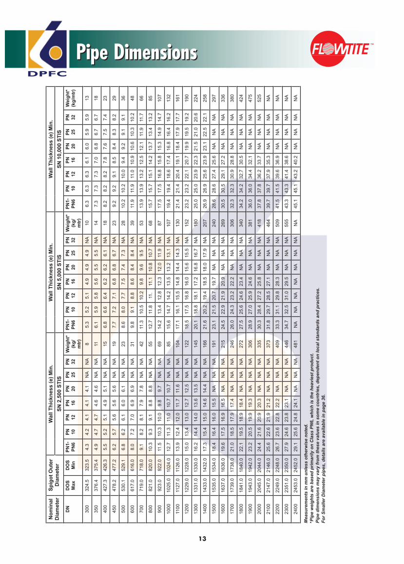
Pipe DimensionsN
omin
al
Dia
met
erSp
igot
Out
er
Dia
met
erW
all T
hick
ness
(e) M
in.
Wal
l Thi
ckne
ss (e
) Min
.W
all T
hick
ness
(e) M
in.
SN 2
,500
STI
SSN
5,0
00 S
TIS
SN 1
0,00
0 ST
ISD
ND
OS
Max
DO
SM
inPN
1-PN
6PN 10
PN 12PN 16
PN 20PN 25
PN 32W
eigh
t*
(kg/
mtr
)
PN1-
PN6
PN 10PN 12
PN 16PN 20
PN 25PN 32
Wei
ght*
(k
g/m
tr)
PN1-
PN6
PN 10PN 12
PN 16PN 20
PN 25PN 32
Wei
ght*
(k
g/m
tr)
300
324.
532
3.5
4.3
4.2
4.1
4.1
4.1
NA
NA
85.
35.
25.
14.
94.
94.
9N
A10
6.3
6.3
6.3
6.1
6.0
5.9
5.9
13
350
376.
437
5.4
4.9
4.7
4.7
4.6
4.6
NA
NA
116.
15.
95.
85.
65.
55.
5N
A14
7.3
7.3
7.3
7.0
6.8
6.7
6.7
18
400
427.
342
6.3
5.5
5.2
5.1
4.9
5.1
NA
NA
156.
86.
66.
46.
26.
26.
1N
A18
8.2
8.2
8.2
7.8
7.6
7.5
7.4
23
450
478.
247
7.2
6.2
5.7
5.6
5.6
5.6
NA
NA
197.
77.
27.
16.
86.
86.
7N
A23
9.2
9.2
9.1
8.5
8.4
8.3
8.2
29
500
530.
152
9.1
6.8
6.2
6.1
6.0
6.1
NA
NA
238.
68.
07.
77.
57.
47.
3N
A28
10.2
10.2
10.0
9.4
9.2
9.1
9.1
36
600
617.
061
6.0
8.0
7.2
7.0
6.9
6.9
NA
NA
319.
89.
18.
88.
68.
48.
4N
A39
11.9
11.9
11.0
10.9
10.6
10.3
10.2
48
700
719.
071
8.0
9.1
8.2
8.1
7.9
7.8
NA
NA
4211
.310
.510
.29.
89.
69.
5N
A53
13.9
13.9
13.2
12.5
12.1
11.9
11.7
66
800
821.
082
0.0
10.3
9.3
9.1
8.8
8.8
NA
NA
5512
.711
.811
. 11
.110
.810
.7N
A68
15.7
15.7
15.1
14.2
13.7
13.4
13.2
85
900
923.
092
2.0
11.5
10.3
10.0
9.8
9.7
NA
NA
6914
.213
.412
.812
.312
.011
.9N
A87
17.5
17.5
16.8
15.8
15.3
14.9
14.7
107
1000
1025
.010
24.0
12.7
11.3
11.0
10.7
10.7
NA
NA
8515
.614
.714
.213
.513
.213
.1N
A10
719
.419
.418
.617
.416
.816
.416
.213
2
1100
1127
.011
26.0
13.9
12.4
12.0
11.7
11.6
NA
NA
104
17.1
16.1
15.5
14.8
14.4
14.3
NA
130
21.4
21.4
20.4
19.1
18.4
17.9
17.7
161
1200
1229
.012
28.0
15.0
13.4
13.0
12.7
12.5
NA
NA
122
18.5
17.5
16.8
16.0
15.6
15.5
NA
152
23.2
23.2
22.1
20.7
19.9
19.5
19.2
190
1300
1331
.013
30.0
16.2
14.4
14.0
13.6
13.5
NA
NA
145
20.1
18.8
18.1
17.2
16.8
16.7
NA
180
25.0
25.0
23.9
22.3
21.5
21.0
20.6
224
1400
1433
.014
32.0
17.3
15.4
15.0
14.6
14.4
NA
NA
166
21.6
20.2
19.4
18.5
18.0
17.9
NA
207
26.9
26.9
25.6
23.9
23.1
22.5
22.1
258
1500
1535
.015
34.0
18.4
16.4
16.0
15.5
NA
NA
NA
191
23.1
21.5
20.7
19.7
NA
NA
NA
240
28.6
28.6
27.4
25.6
NA
NA
NA
297
1600
1637
.016
36.0
19.6
17.5
16.9
16.5
NA
NA
NA
215
24.5
22.9
21.9
20.9
NA
NA
NA
269
30.5
30.5
29.1
27.2
NA
NA
NA
336
1700
1739
.017
38.0
21.0
18.5
17.9
17.4
NA
NA
NA
246
26.0
24.3
23.2
22.2
NA
NA
NA
306
32.3
32.3
30.9
28.8
NA
NA
NA
380
1800
1841
.018
40.0
22.1
19.5
18.9
18.4
NA
NA
NA
272
27.5
25.6
24.6
23.4
NA
NA
NA
340
34.2
34.2
32.7
30.5
NA
NA
NA
424
1900
1943
.019
42.0
23.2
20.5
19.9
19.3
NA
NA
NA
306
28.9
27.0
25.9
24.6
NA
NA
NA
381
36.0
36.0
34.4
32.1
NA
NA
NA
475
2000
2045
.020
44.0
24.4
21.6
20.9
20.3
NA
NA
NA
335
30.3
28.4
27.2
25.8
NA
NA
NA
418
37.8
37.8
36.2
33.7
NA
NA
NA
525
2100
2147
.021
46.0
25.6
22.6
21.9
21.2
NA
NA
NA
373
31.8
29.7
28.5
27.1
NA
NA
NA
464
39.7
39.7
37.9
35.3
NA
NA
NA
NA
2200
2249
.022
48.0
26.7
23.6
22.8
22.2
NA
NA
NA
409
33.3
31.1
29.8
28.3
NA
NA
NA
509
41.5
41.5
39.6
36.9
NA
NA
NA
NA
2300
2351
.023
50.0
27.9
24.6
23.8
23.1
NA
NA
NA
446
34.7
32.5
31.0
29.5
NA
NA
NA
555
43.3
43.3
41.4
38.6
NA
NA
NA
NA
2400
2453
.024
52.0
29.1
25.6
24.8
24.1
NA
NA
NA
481
NA
NA
NA
NA
NA
NA
NA
NA
45.1
45.1
43.2
40.2
NA
NA
NA
NA
Mea
sure
men
ts in
mm
unl
ess
othe
rwis
e no
ted.
*Pip
e w
eigh
ts a
re b
ased
prim
arily
on
Cla
ss P
N6,
whi
ch is
the
heav
iest
pro
duct
.Pi
pe d
imen
sion
s m
ay v
ary
from
thes
e va
lues
in s
ome
coun
trie
s, d
epen
dent
on
loca
l sta
ndar
ds a
nd p
ract
ices
.Fo
r Sm
alle
r Dia
met
er p
ipes
, det
ails
are
ava
ilabl
e in
pag
e 36
.

DPFC
Couplings Dimensions
14
Couplings DimensionsN
omin
al
Dia
met
erO
uter
D
iam
eter
CD
KL
Wei
ght*
* (k
gs/u
nit)
DN
DO
SM
axP
N1-
PN
6P
N 10P
N 12P
N 16P
N 20P
N 25P
N 32P
N1-
PN
6P
N 10P
N 12P
N 16P
N 20P
N 25P
N 3230
032
4.5
367
368
369.
036
7*38
5*38
5*39
0*27
027
027
027
027
027
027
012
350
376.
441
942
042
1.0
422
432*
432*
437*
270
270
270
270
270
270
270
1440
042
7.3
469
471
472.
047
348
348
348
427
027
027
027
027
027
027
016
450
478.
252
052
252
3.0
524
534
534
534
270
270
270
270
270
270
270
1850
053
0.1
572
574
574.
057
658
658
658
627
027
027
027
027
027
027
020
600
617.
066
566
766
7.0
669
679
679
679
330
330
330
330
330
330
330
3270
071
9.0
768
770
770.
077
478
478
479
233
033
033
033
033
033
033
040
800
821.
087
087
387
4.0
879
889
889
909
330
330
330
330
330
330
330
4790
092
3.0
972
977
977.
098
399
310
0010
20*
330
330
330
330
330
330
330
5510
0010
25.0
1075
1080
1081
.010
8710
9711
0911
28*
330
330
330
330
330
330
330
6311
0011
27.0
1176
1181
1184
.011
8811
9011
88*
1225
*33
033
033
033
033
033
033
071
1200
1229
.012
8012
8412
87.0
1291
1301
1313
*13
30*
330
330
330
330
330
330
330
7413
0013
31.0
1381
1387
1390
.013
9314
0414
22*
1437
*33
033
033
033
033
033
033
086
1400
1433
.014
8514
9014
93.0
1499
1510
1525
*15
42*
330
330
330
330
330
330
330
9115
0015
35.0
1586
1593
1596
.016
02N
AN
AN
A33
033
033
033
0N
AN
AN
A10
816
0016
37.0
1689
1696
1699
.017
06N
AN
AN
A33
033
033
033
0N
AN
AN
A11
917
0017
39.0
1791
1798
1802
.0N
AN
AN
AN
A33
033
033
0N
AN
AN
AN
A10
5***
1800
1841
.018
9419
0219
05.0
NA
NA
NA
NA
330
330
330
NA
NA
NA
NA
107*
**19
0019
43.0
1996
2003
2009
.0N
AN
AN
AN
A33
033
033
0N
AN
AN
AN
A12
0***
2000
2045
.020
9921
0721
12.0
NA
NA
NA
NA
330
330
330
NA
NA
NA
NA
127*
**21
0021
47.0
2200
2209
NA
NA
NA
NA
NA
330
330
330
NA
NA
NA
NA
136*
**22
0022
49.0
2303
2312
NA
NA
NA
NA
NA
330
330
330
NA
NA
NA
NA
145*
**23
0023
51.0
2405
2414
NA
NA
NA
NA
NA
330
330
330
NA
NA
NA
NA
154*
**24
0024
53.0
2508
2517
NA
NA
NA
NA
NA
330
330
330
NA
NA
NA
NA
163*
**
Mea
sure
men
ts in
mm
unl
ess
othe
rwis
e no
ted.
*Dim
ensi
ons
are
only
app
roxi
mat
e. C
oupl
ings
are
ove
rwra
pped
to a
chie
ve th
e ra
ted
pres
sure
.**
PN16
***P
N10

DPFC
Fittings
15
Fittings
DPFC-GRP has created a standardized line of GRP fittings that are molded or fabricated using the same materials that are used to produce GRP pipe. One of the benefits of DPFC-GRP pipe is the ability to fabricate a wide assortment of fittings, standard as well as non-standard.
Fittings
Elbows
Wyes
Eccentric Reducers
Flanges Saddles
Concentric Reducers
Tees

DPFC
Shipping, Handling and Storage
16
Inspecting PipeAll pipes should be inspected upon receipt at the job site to ensure that no damage has occurred in transit. Re-inspection of the pipe just prior to installation is advisable. Inspect the shipment upon delivery, as follows:1. Make an overall inspection of the load. If the
load is intact, ordinary inspection while unloading will normally be sufficient to make sure the pipe has arrived without damage.
2. If the load has shifted or indicates rough treatment, carefully inspect each pipe section for damage. Generally, an exterior inspection will be sufficient to detect any damage.
3. If any imperfection or damage is found, immediately segregate the affected pipes and contact DPFC.
4. Do not use pipe that appears damaged or defected.
Repairing PipeNormally, pipes with minor damage can be repaired quickly and easily at the job site by a qualified individual. If in doubt about the condition of the pipe, do not use the pipe. The Field Service Representative can help you determine whether repair is required and whether it is possible and practical. He can obtain the appropriate repair specification and arrange for the required materials and a trained repair technician, if desired. Repair designs can vary greatly due to pipe thickness, wall composition, application, and type and extent of damage. Therefore, do not attempt to repair a damaged pipe without consulting DPFC first. Improper repaired pipes may not perform as intended.
Unloading and Handling PipeUnloading the pipe is the responsibility of the customer. Be sure to maintain control of the pipe during unloading. Guide ropes attached to pipes or packages will enable easy manual control when lifting and handling. Spreader bars may be used when multiple support locations are necessary. Do not drop, impact, or bump the pipe, particularly at ends.
Shipping, Handling and Storage
Pipes packages may be handledusing a pair of slings as shown in Figure 5.
Figure 5
Single Pipes:Single pipes must be unloaded and handled separately (one at a time). Use pliable straps, slings or ropes to lift single pipes. Do not use steel cables or chains to lift or transport the pipe. Pipe sections can be lifted with only one support point (Figure 6) although two support points placed as in Figure 7 make the pipe easier to control. Do not lift pipes by passing a rope through the section end to end. See page 13 & 14 for appropriate weights of standard pipes and couplings. If at any time during handling or installation of the pipe, any damage such as gouge, crack, or fracture occurs, the pipe should be repaired before the section is installed. Contact DPFC for inspection of damage and for recommendation for repair method or disposal. See previous section on Repairing Pipe.
1/4 x L1/4 x L 1/2 x L

DPFC
17
Figure 6
Lifting Pipe at One Support Point
Figure 7
Lifting Pipe at Two Support Points
Storing PipeIt is generally advantageous to store pipes on flat timber to facilitate placing and removal of liftingslings around the pipe. When storing pipe directly on the ground, be sure that the area is relatively flat and free of rock and other potentially damaging debris. All pipes should be chocked to prevent rolling in high winds.
If it is necessary to stack pipes, it is best to stack on flat timber supports at maximum 6 meter spacing (3 meter for small diameter) with chocks (See Figure 8).
Insure the stack will be stable for conditions such as high winds, un-level storage area or other horizontal loads. Maximum stack height is approximately 3 meters. Stacking of pipes larger than 1400mm diameter is not recommended. Maximum diametrical deflection must not exceed the values in Table 16. Bulges, flat areas or other
abrupt changes of curvature are not permitted. Storing of pipes outside these limitations may result in damage to the pipes.
Figure 8
Table 16
Maximum Storage Deflections Maximum Deflection Stiffness Class SN (% of Diameter) 2500 2.5 5000 2.0 10000 1.5
Storing Gaskets and LubricantRubber ring gaskets, when shipped separate from the couplings, must be protected from exposures to grease or oils, which are petroleum derivatives, and from solvents and other deleterious substances.
Shipping, Handling and StorageShipping, Handling and Storage Continued
1/4 x L1/4 x L 1/2 x L
DPFC
18
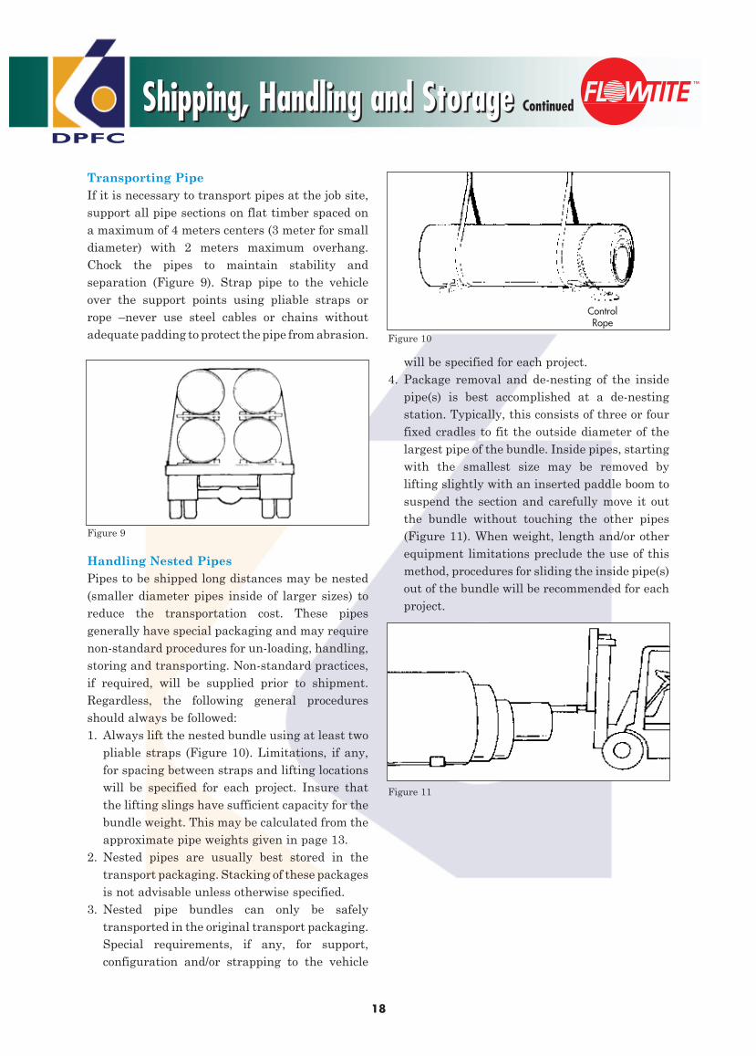
Transporting PipeIf it is necessary to transport pipes at the job site, support all pipe sections on flat timber spaced on a maximum of 4 meters centers (3 meter for small diameter) with 2 meters maximum overhang. Chock the pipes to maintain stability and separation (Figure 9). Strap pipe to the vehicle over the support points using pliable straps or rope –never use steel cables or chains without adequate padding to protect the pipe from abrasion.
Handling Nested PipesPipes to be shipped long distances may be nested (smaller diameter pipes inside of larger sizes) to reduce the transportation cost. These pipes generally have special packaging and may require non-standard procedures for un-loading, handling, storing and transporting. Non-standard practices, if required, will be supplied prior to shipment. Regardless, the following general procedures should always be followed:1. Always lift the nested bundle using at least two
pliable straps (Figure 10). Limitations, if any, for spacing between straps and lifting locations will be specified for each project. Insure that the lifting slings have sufficient capacity for the bundle weight. This may be calculated from the approximate pipe weights given in page 13.
2. Nested pipes are usually best stored in the transport packaging. Stacking of these packages is not advisable unless otherwise specified.
3. Nested pipe bundles can only be safely transported in the original transport packaging. Special requirements, if any, for support, configuration and/or strapping to the vehicle
will be specified for each project.4. Package removal and de-nesting of the inside
pipe(s) is best accomplished at a de-nesting station. Typically, this consists of three or four fixed cradles to fit the outside diameter of the largest pipe of the bundle. Inside pipes, starting with the smallest size may be removed by lifting slightly with an inserted paddle boom to suspend the section and carefully move it out the bundle without touching the other pipes (Figure 11). When weight, length and/or other equipment limitations preclude the use of this method, procedures for sliding the inside pipe(s) out of the bundle will be recommended for each project.
Figure 9
Figure 10
Figure 11
Shipping, Handling and StorageShipping, Handling and Storage Continued
ControlRope

DPFC
General Installation
19
General Installation
Long life and the good performance characteristics of GRP pipe can only be achieved by proper handling and installation of the pipe. It is important for the owner, engineer and contractor to understand that glass-reinforced plastic (GRP) pipe is designed to utilize the bedding and pipe zone backfill support that will result from recommended installation procedures. Engineers have found through considerable experience that properly compacted granular materials are ideal for backfilling GRP pipe. Together, the pipe and embedment material form a high performance “pipe-soil system”.
The following information is a partial review of installation procedures; it is not intended to replace the installation instructions which must be followed for any project.
TrenchingDetails of a standard trench must always be wide enough to permit placement and compaction of the pipe zone backfill materials and provide proper pipe support. The depth of cover charts presented in this brochure are based on an assumed trench width 1.75 times the pipe’s nominal diameter. Widths down to 1.5 times DN may be achievable, however the burial limits will be affected. Consult us if your conditions will vary from these assumptions.
BeddingThe trench bed, of suitable material, should provide uniform and continuous support for the pipe.
Backfill MaterialsTo ensure a satisfactory pipe-soil system, correct backfill material must be used. Most coarse grained soils (as classified by the Unified Soils Classification system) are
acceptable bedding and pipe zone backfill material. Where the instructions permit the use of native soil as backfill, care should be taken to ensure that the material does not include rocks, soil clumps, debris, frozen or organic material. Table 17 identifies acceptable backfill soils.
Standard Trench DetailsMinimum Width Trench
Dimension “A” is a minimun of .75* DN/2
Provide 100 to 200 mm bedding below the pipe
Checking the Installed PipeAfter installation of each pipe, the maximum diametrical vertical deflection must be checked. With DPFC-GRP pipe this procedure is fast and easy.
Installed Diametrical DeflectionThe maximum allowable initial diametrical deflection (typically vertical) shall be 3% for diameters 300mm and larger, and max 5% is the long-term allowable deflection. These values will apply to all stiffness classes.
Bulges, flat areas or other abrupt changes of pipe wall curvature are not permitted. Pipe installed outside of these limitations may not perform as intended.
Table 17
Backfill Soil Descripion Unified Soil Classification Type Designation, ASTM D2487
A Crushed stone and gravel, < 12% fines GW, GP, GW- GP - GM
B Gravel with sand, sand, < 12% fines GW - GC, GP - GC, SW, SP, SW-SM, SP-SM, SW-SC, SP-SC
C Silty gravel and sand, 12 - 35% fines, LL < 40% GM, GC, GM - GC, SM, SC, SM - SC
D Silty, clayey sand, 35 - 50% fines, LL < 40% GM, GC, GM - GC, SM, SC, SM - SC
E Sandy, clayey silt, 50 - 70% fines, LL < 40% CL, ML, CL - ML
F Low plasticity fine-grained soils, LL < 40% CL, ML, CL - ML
DPFC
20
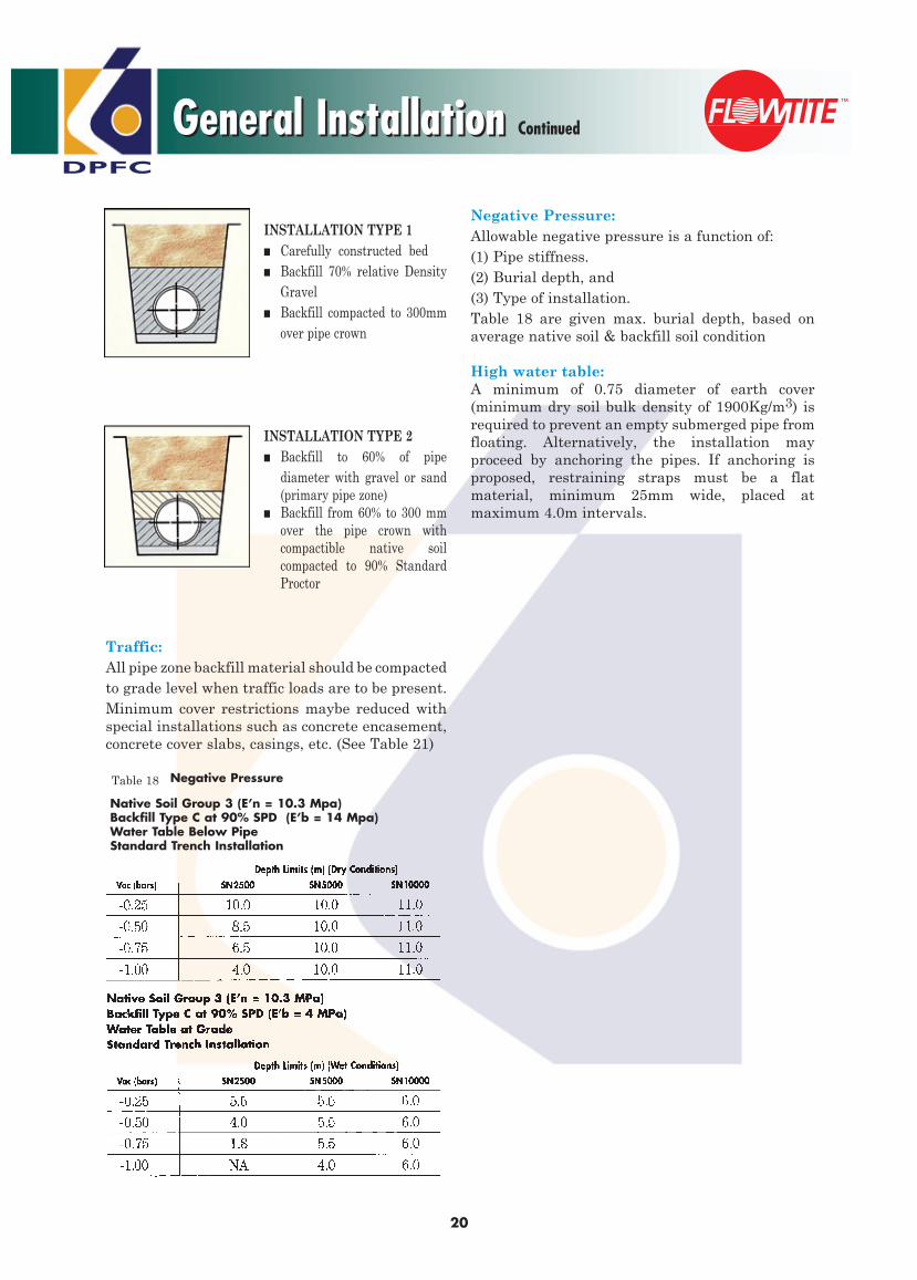
Negative Pressure:Allowable negative pressure is a function of:(1) Pipe stiffness.(2) Burial depth, and(3) Type of installation.Table 18 are given max. burial depth, based on average native soil & backfill soil condition
High water table:A minimum of 0.75 diameter of earth cover (minimum dry soil bulk density of 1900Kg/m3) is required to prevent an empty submerged pipe from floating. Alternatively, the installation may proceed by anchoring the pipes. If anchoring is proposed, restraining straps must be a flat material, minimum 25mm wide, placed at maximum 4.0m intervals.
Traffic:All pipe zone backfill material should be compacted to grade level when traffic loads are to be present. Minimum cover restrictions maybe reduced with special installations such as concrete encasement, concrete cover slabs, casings, etc. (See Table 21)
INSTALLATION TYPE 1■ Carefully constructed bed■ Backfill 70% relative Density
Gravel■ Backfill compacted to 300mm
over pipe crown
INSTALLATION TYPE 2■ Backfill to 60% of pipe
diameter with gravel or sand (primary pipe zone)
■ Backfill from 60% to 300 mm over the pipe crown with compactible native soil compacted to 90% Standard Proctor
General InstallationGeneral Installation Continued
Table 18
Native Soil Group 3 (E’n = 10.3 Mpa)Backfill Type C at 90% SPD (E’b = 14 Mpa)Water Table Below PipeStandard Trench Installation
Negative Pressure

DPFC
General Installation
21
General Installation Continued
Table 20
Table 19
Table 21

DPFC
22
Factors Affecting InstallationFactors Affecting Installation
Installation Types
Type 1 (full embedment) Type 1a (full embedment) Type 2 (split embedment)
Installation Design Process RECORD DATA:
Fill to gradewith native soil
Compactedbackfill as
specified frombedding to
300 mm overpipe crown
Fill to gradewith native soil
Compact backfillfrom 60% of DN to300mm over pipecrown, compacted,
if necessary, toachieve a minimummodulus of 1.4 mPa
Compactedbackfill as
specified frombedding to 60%of pipe diameter
Compactedbackfill as
specified frombedding topipe crown
1. Define diameter Effluent: DN:2. Select pressure class PN:3. Define native soil classification Group:4. Check minimum depth of cover and operating pressure OK?5. Check minimum depth of cover for traffic load OK?6. Define native pressure (vacuum) Negative pressure (Vacuum):7. Select trench type Type (full or split):8. Check allowable burial depth and select SN and E’b SN: E’b:9. Select alternate trench construction, if necessary Alternative:10. Select backfill soil type and degree of compaction Type: %:
A. Depth of Cover: Maximum allowable depth of
cover is affected by: • Backfill soil modules • Trench width • Native soil modules • Traffic load • Pipe stiffness • Water table elevation • Negative pressureB. Pipe Diameter (DN) DN Determines: • Bedding depth • Trench widthC. Pipe Zone: The area from the bottom of
the bedding to 300mm over the crown of the pipe is defined as the pipe zone.
D. Compacted Backfill: The soil modules, E’b, of the
backfill material depends on type and degree of compaction.
E. Trench Width: Minimum trench width is a
function of pipe diameter. Standard Width = 1.75 x DN.F. Side Clearance: Sufficient side clearance must
be allowed to permit specified compaction of haunching and backfill soil.
G. Depth of Bedding: The compacted bedding for the
pipe is calculated as DN/4 with a maximum depth of 150 mm.
Traffic Load
Fill-to-Grade
Native Soil
BackfillMaterial
DPFCGRP
OperatingPressure
NegativePressure
GeologicConditions
Haunching
Bedding
Water Table
A.
E.
B.
G.
F.C.
D.

DPFC
Pipe Joining
23
Double Bell CouplingThe following steps apply to all doublebell coupling joining procedures:
Step 1: Clean Coupling
Thoroughly clean double bell coupling groovesand rubber gasket rings to make sure no dirt oroil is present (Figure 12).
Step 2: Install Gaskets
Insert the gasket into the grooves, leaving two or more uniform loops of rubber (depending on diameter) extending out of the groove. Do not put any lubricant in the groove or on the gasket at this stage. There should be a minimum of one loop for each 450mm of gasket ring circumference(Figure 13).
With uniform pressure, push each loop of the rubber gasket into the gasket groove. When installed, pull carefully on the gasket in the radial direction around the whole circumference to check for well-distributed compression of the gasket. Check also that both sides of the gasket protrude
Joining pipesDPFC-GRP pipe sections are typically joined using GRP double bell couplings. Pipe and coupling will be supplied separately.
Other joining systems such as flanges, mechanical couplings and lay-up joints may also be used with DPFC-GRP pipe.
equally above the top of the groove around the whole circumference.
Tapping with a rubber mallet will be helpful to accomplish the above.
Step 3: Lubricate GasketsNext,using a clean cloth, apply a thin film of lubricant to the rubber gaskets (Figure 14).
Step 4: Clean and Lubricate SpigotsThoroughly clean pipe spigots to remove any dirt, grit, grease, etc. Using a clean cloth, apply a thin film of lubricant to the spigots from the end of the pipe to the black positioning stripe. After lubricating, take care to keep the coupling and spigot clean (Figure 15).
Caution: It is very important to use only the correct lubricant. Never use a petroleum based lubricant.
Pipe Joining
Figure 12
Figure 13
Figure 14
Figure 15

DPFC
24
Step 5: Fixing of ClampsClamp A is fixed anywhere on first pipe or left in position from previous joint. Fix Clamp B on the pipe to be connected in the correct position relative to the alignment stripe on the spigot-end (home-line) so as to act as a stopper (Figure 16).
Note: The mechanical installation clamp is to act both as a stopper to position the coupling and as a device on which to attach the pulling (come-along jacks) equipment. Clamp contact with the pipe shall be padded or otherwise protected to prevent damage to the pipe and to have high friction resistance with the pipe surface. If clamps are not available, nylon slings or rope may be used as in Figure 17, but care must be taken in the alignment of the coupling. A pipe clamp has the advantage of acting as a stopper. However, if not available, insert the pipe spigots until the home-line (alignment stripe) aligns with the coupling edge.
Step 6: Pipe PlacementThe pipe to be connected is placed on the bed with sufficient distance from previously joined pipe to allow lowering the coupling into position.
Step 7: Join CouplingCome-along jacks are installed to connect the pipe clamps and two 10cm x 10cm timbers or similar (larger diameters require a bulkhead) are placed between the pipe previously connected and the
coupling. While these are held in position the new pipe is entered into the coupling until it rests against the pipe clamp. Come-along jack might need protective blanket under it in order not to touch against the pipe (Figure 17).
Note: Approximate joining force 1 kg/mm ofdiameter.
Step 8: Join PipesCome-along jacks are loosened and timbers removed before re-tightening the jacks for entering the coupling onto the previously connected pipe. Check the correct position of the edge of the coupling to the alignment stripe (Figure 18).
Note: When step 8 has been completed, Clamp-B is left in position while Clamp A is moved on to the next pipe to be joined.
Figure 16
Figure 18
Figure 17
Figure 19
Pipe JoiningPipe Joining Continued

DPFC
25
Flanged JointsGRP flanges should be joined according to the following procedure: (Figure 20) 1. Thoroughly clean the flange face. 2. Ensure the gasket is clean and undamaged. Do not use defective gaskets. 3. Place the gasket in position, if necessary, with
small strips of adhesive tape. 4. Align flanges to be joined. 5. Insert bolts, washers, and nuts. All hardware must be clean and lubricated to avoid incorrect tightening. Washers must be used on all GRP flanges. 6. Using a torque wrench, tighten all bolts to 35 N.m (25 lb.ft) torque, following standard flange bolt tightening sequences. 7. Repeat this procedure, raising the bolt torque to 70 N.m (50 lb.ft) or until the flanges touch at their inside edges. 8. Check bolt torque one hour later and adjust if necessary. Note: When connecting two GRP flanges, only one flange should have a gasket groove in the face.
Other Joining MethodsFlexible Steel Couplings:(Straub, Tee Kay, etc.–See Figure 21)These couplings can be used for joining as well as for repair. The coupling consists of a steel mantle with an interior rubber sealing sleeve.Three grades are available:A. Epoxy or PVC-coated steel mantle.B. Stainless steel mantle.C. Hot dip galvanized steel mantle.
Control of bolting torque with these couplings is most important. After initial bolt up, the coupling should be rapped with a rubber mallet to help seat and flow the gasket. Bolt torque should then be adjusted up to proper levels. Depending on coupling size, this procedure may need to be repeated several times. Do not over torque as this may over stress the bolts. Follow the manufacturer’s recommended assembly instructions.
3.3.2 Mechanical Steel Couplings:(Viking Johnson, Dresser etc.–See Figure 22)These couplings can be used for joining, typically to other types of pipe or to rigid items. Bolting torque must be controlled to not exceed the manufacturer’s maximum recommended values. Excess torque could damage the pipe.
Figure 21
Figure 20
Flanges
Figure 22
Pipe JoiningPipe Joining Continued

DPFC
26
UNDERGROUND PIPING SYSTEM - COUPLING JOINTSField Hydrotest could be conducted in segments or as a complete piping system :
Segment HydrotestingsCertain lengths shall be chosen according to site conditions to test the installed piping system in segments. A clearance of 4 meters minimum shall be maintained between the segments which could be later installed as Make-up pipe piece with double spigot calibration to facilitate the joining on existing piping segment.
FIXING TEST PLUGS :There are more than one method to close temporarily the pipe ends for hydrotest purposes :
1. USING BLIND END CAPS :Blind end cap is GRP coupling with one end closed through lamination, while the other end is with groove for rubber gasket to work as sealing the end.
Fix the end cap with the last pipe end to be tested after placing the rubber gasket into end cap groove.
Join with the spigot pipe end through pullers/come-along jacks.
Necessary openings could be provided to the end caps for ventilation/pressure gauge. After segment test, these end caps could be removed through pullers & upon rubber gasket replacement, could be reused for other segments. End caps are available with DPFC upon separate purchase order.
Adequate concrete block supports shall be provided to the end cap to prevent the pipe movement during hydrotest.
2. FLANGED BLIND END :Flanged blind end is a spool consisting of flange with pipe piece & blind through a blind flange with bolts at one end while the other end is a spigot calibrated pipe and shall be joined with the
existing end by coupling.*Further details of above options are available upon request
CHECK LIST PRIOR TO PIPE ENDS BLIND :To check each coupling joint is connected correctly and the clearance between the pipe end is uniform all around. (Field joints testing equipment is available upon separate Purchase Order for pipe diameters ranging from 700mm to 2400mm. This test ensures the rubber gasket correct positioning inside the double bell coupling groove. The test shall be conducted prior to start backfill. For details, contact Dubai Pipes Factory Co. - Field Representative).
Internal visual inspection shall be carried out for accessible pipe diameters for any possible damage during installation/backfilling.
Vertical deflection measurements shall be taken to observe the pipe behaviour after the backfill.
Make sure that the pipes are backfilled to the minimum cover depth requirements of hydrotest.
For 300mm diameters: Min. 600mm cover over the pipe crown.
For 350mm diameters & onwards: Min. 1000mm cover over the pipe crown.Double bell coupling joints could be exposed in case of the
client requirements.
Make sure that the backfilling slope at the joints location is maintained with minimum pipe exposure.
PREPARATION PRIOR TO HYDROTEST :Make sure that the test method statement is available with full understanding of implementation to the testing team.
Allowance for each branch / manhole to move freely, within limits during the hydrotest.
Fixing ventilation at highest points, minimum two pressure gauges and filling points with valves.
Field Hydrotest-G.R.P. PipingField Hydrotest-G.R.P. Piping

DPFC
27
The values and reading at the pressure shall be calculated taking into account the static head between the lowest pipe invert level along the complete line and the level of the pressure gauge.
All flanges are tightened to the specified torque bolt sequence. Make sure that the valves are anchored and the above ground piping, if any, is supported as specified.
In no case, shall a single person be allowed to get inside of the piping for inspection.
Upon verification of the inspection, when the findings are all judged acceptable & recorded, manhole covers shall be closed.
Prior to start water filling, temporary piping & blinds shall be installed checked & verified by the client /consultant /contractor representatives.
WATER FILLING & PRESSURIZING THE SYSTEM :(It shall be confirmed that all vent points are fully opened to atmosphere, prior to start water filling).
Introduce water filling through temporary hosing & pump at lowest point. Pump capacity shall be chosen according to the pipe diameter and segment /system linear length. (Pumps having 100m3
capacity /hour are generally used for large diameter pipes).
The sign of complete water filling is when the water starts coming through a higher ventilation point of an opened valves.
Stop water pumps at this stage & check the flanges, valves and connected accessories for any weepage /leakage, while keeping the vents open.
PRESSURIZING :Start pressurizing the segment / system through the pump. Once the water starts coming out through the vent opening, close the valves at the low elevation. Later, on the high elevation end, the vent valves shall be closed as when water
starts coming. The pressure increment shall be maintained approx. as 0.5 Bar /10 minutes at this stage. When the pressure reaches to 2 bar, the pumps shall be stopped.
Keep this stoppage for 15-20 minutes. During this time, following checks shall be made :
A) Pressure at each test gauge shall be checked & recorded on inspection sheet.B) Watch the pressure at the water feed point for any decrease in pressure.C) Walk through along with the underground lines to observe any traces of wet soil. Check the coupling joints, if exposed.
The inspection sheet shall be maintained for the observations & findings.Anything unusual shall be immediately reported to the team leader.
Unless there is no findings which prevent the test from continuing, the segment/system shall be further pressurized.
Connect the hose with the pressure pump and start pressurizing the line. At this stage, slightly open the vent. Valve should be fixed at a higher elevation to ensure that no entrapped air is present.
Upon confirmation of water coming out of the vent, valve shall be closed. The system is now totally closed and under pressure.
Continue pressurizing until pressure reaches 5.0 Bar.
Stop the pressure pump once it reaches to 5.0 Bar and let is stabilize.
There could be a drop in pressure due to the thermal expansion, which could be resolved by restarting the pump or keep it as is & record it on the inspection sheet.
Keep this stoppage for about 30 minutes. During
Field Hydrotest-G.R.P. PipingField Hydrotest-G.R.P. Piping Continued

DPFC
28
this period, repeat the same sequence of inspection as described earlier. The findings & observations shall be recorded on inspection sheets.Any unusual findings shall be reported immediately to the team leader.
Unless there is no finding which prevents the test from continuing, the segment/system shall be further pressurized to the requirement.
The test pressure should not exceed 1.5 times the maximum rated operating pressure. The test pressure shall be maintained for a minimum period of time.
(It is recommended to maintain the test hold time to a maximum of 15 minutes after pressure stabilization).
A thorough inspection shall be made as FINAL INSPECTION.
Fill up the inspection sheets accordingly.
The test shall be considered as “PASS” if no signs of leakage is observed
The inspection sheet(s) shall be signed by the authorities.
POST HYDROTEST:After completion of the test, drain or flush out the filled water from the pipe segment/system through drain valves & vents shall be opened. This pressure release shall be made slowly at 2 bar /5 minutes.
Remove the end cap from the segment as per procedure.
Prepare the pipe end to be ready for next installation.
Exposed joints may be backfilled using the specified backfill material.
Connect the adjacent segment ends with closure pipe piece.
Continue the installation for the other segments & conduct the hydrotest in the similar manner as described earlier. Keep connecting the segments through closure spools.
COMPLETE SYSTEM hydrotest /Final hydrotestPurpose of this hydrotest is to test the pipe closure spools joints.
Following arrangements shall be made :1- All branch connections shall be kept free to move.2- Separate the line from all connecting equipments.3- Exposure of joints at closure pipe piece shall be done manually in order to prevent the pipe from any damage.
The procedure described for the segment testing is applicable to the final hydrotest.
For final hydrotest, it is recommended to maintain the test hold pressure for minimum period of time (to inspect the joint/fittings) and the pressure shall be equal to the maximum rated operating pressure.
Field Hydrotest-G.R.P. PipingField Hydrotest-G.R.P. Piping Continued

DPFC
Surge & Water Hammers
29
Water hammer or pressure surge is the sudden rise or fall in pressure caused by an abrupt change in the fluid velocity within the pipe system. The usual cause of these flow changes is the rapid closing or opening of valves, or sudden starting or stopping of pumps such as during a power failure. The most important factors which influence the water hammer pressure in a pipe system are the change in velocity of the fluid, rate of change of the velocity (valve closing time), compressibility of the fluid, stiffness of the pipe in the “hoop” direction, and physical layout of the pipe system.
The water hammer pressure expected for GRP pipe is approximately 50% of that for steel and ductile iron pipe, for similar conditions. The pipe has a surge pressure allowance of 40% of the nominal pressure, as shown in Table 22.
An approximate relationship for the maximum pressure variation at a given point in a straight pipeline with negligible friction loss can be calculated from the formula : H = (w v)/g Where : H = change in pressure (meters)
w = surge wave celerity (meters/sec)
v = change in liquid velocity (meters/sec)
g = acceleration due to gravity (meters/sec2)
Table 22
Surge Wave Celerity for
DPFC- GRP Pipes
DN 300-400 450-800 900-2500 Meters/Sec.
SN2500
PN6 365 350 340
PN10 435 420 405
PN16 500 490 480
SN5000
PN6 405 380 370
PN10 435 420 410
PN16 505 495 480
PN25 575 570 560
SN10000
PN6 420 415 410
PN10 435 425 415
PN16 500 495 485
PN25 580 570 560
PN32 620 615 615
Surge & Water Hammers

DPFC
Thrust Blocks, Concrete Encasement, Rigid Connections
30
Thrust Blocks, Concrete Encasement, Rigid Connections
Thrust RestraintsWhen the pipeline is pressurized, unbalanced thrust forces occur at bends, reducers, tees, wyes, bulkheads and other changes in line direction. These forces must be restrained in some manner to prevent joint separation. When the surrounding soil cannot provide this restraint, thrust or stress /thrust blocks must be used. Determination of need and design of these restraints is the responsibility of the owner’s engineer subject to the following limitations:
Thrust/Stress BlocksThrust/stress blocks must limit the displacement of the fitting to 0.5% of the diameter or 6mm whichever is less. They must also restrict the radial deformation of the fitting to 0.1% of the respective pipe sections. For operating pressures above 10 bar, the block must completely surround the fitting for its entire length and circumference (Figure 23) and should be placed either against undisturbed earth or backfilled with pipe zone material as appropriate for the native soil characteristics. These blocks are required for the fittings when the line pressure exceeds 1 bar (100KPA): These blocks are applicable to:1- All bends, reducers, bulkheads and blind flanges.
2- Tees: When the branch pipe is concentric to the header pipe centerline.
3- Valves: Valves must be sufficiently anchored to absorb the pressure thrust.
4- Nozzles: Nozzles are tee branches meeting all the following criteria:
i- Nozzle diameter ≤300mm. ii- Header diameter ≥3 times nozzle diameter. iii- If the nozzle is not concentric and/or not
perpendicular to the header pipe axis, thenozzle diameter shall be considered to bethe longest chord distance on the headerpipe wall at the nozzle/pipe intersection.
Note: It is not necessary to encase nozzle connections in concrete.
Figure 23
Section A-A
One Miter Bend:0-30º
Two Miter Bend:31-60º
Three Miter Bend:61-90º
ConcreteThrust Blocks
Tee ReducerA
A
A
A
A
A
A A
A A

DPFC
31
Concrete EncasementWhen pipes must be encased in concrete,such as for thrust blocks, stress blocks, or to carry unusual loads, specific additions to the installation procedures must be observed.
Pipe AnchoringDuring the pouring of the concrete, the empty pipe will experience large uplift (flotation) forces. The pipe must be restrained against movement that could be caused by these loads. This is normally accomplished by strapping over the pipe to a base slab or other anchor(s). Straps should be a flat material of minimum 25mm width, strong enough to withstand flotation uplift forces, spaced not to exceed 4 meters, with a minimum of one strap per section length. The straps should be tightened to prevent pipe uplift, but not so tight that additional pipe deflection is caused.
Pipe SupportsThe pipe should be supported in such a way that the concrete can easily flow completely around and fully underneath the pipe. Also, the supports should result in an acceptable pipe shape (less than 3% deflection and no bulges or flat area). Supports are normally placed at strap locations (not exceeding 4 meter spacing)(Figure 25).
Concrete PouringThe concrete surround must be placed in stages allowing sufficient time between layers for the cement to set (no longer exert buoyant forces). Maximum lift height is variable with nominal pipe stiffness:
STIS 2500 — Larger of 300mm or 1/4 pipe DN.STIS 5000 — Larger of 450mm or 1/3 pipe DN.STIS 10000 — Larger of 600mm or 1/2 pipe DN
Rigid ConnectionsWhen a pipe passes through a wall, or encased in concrete, or meets a junction with a manhole, or is flanged to a pump, valve, or other structure, excessive bending stresses may develop in the pipe if differential movement occurs between the pipe and the rigid connection. For all rigid connections action must be taken by the installer to minimize the development of high discontinuity stresses in the pipe. Two options are available. Alternate A (preferred) uses a coupling joint cast into the concrete-pipe interface. Alternate B wraps the pipe in rubber to ease the transition.
Where possible, cast a coupling joint in the concrete at the interface (Figure 26) so that the first pipe outside the concrete has complete freedom of movement (within the joint limits).
Caution1- When casting a coupling in concrete, be sure to maintain its roundness, so later joint assembly may be accomplished easily. Alternatively, make up the joint outside the encasement prior to pouring the concrete.2- Since the coupling cast in concrete is rigid, it is important to minimize the vertical deflection and deformation of the adjacent pipe.
Where the standard method is not possible, wrap a band (or bands) of rubber around the pipe prior to placement of any concrete, such that the rubber slightly protrudes (25 mm) from the concrete. Layout the pipeline so the first completely exposed coupling joint is located as shown in Figure 27.
Thrust Blocks, Concrete Encasement, Rigid ConnectionsThrust Blocks, Concrete Encasement, Rigid Connections Continued
Figure 24
Figure 25
max.4 meters
min..25 meters
Max. 4 meters
Clear area

DPFC
32
Construction Guidelines
1. When the design of the concrete structure is considered, it should be noted that any excessive settlement of the structure relative to the pipe can be the cause of a pipe failure.2. The pipeline layout shall be such that the first pipe section near the rigid connection is a short length (rocker pipe) as follows : (See Figures 26 and 27)Minimum : larger of 1 meter or 1 diameterMaximum : larger of 2 meters or 2 diameters This rocker pipe section is used to account for some differential settlements that may occur. The rocker pipe should have straight alignment with the concrete structure at the time of installation to provide maximum flexibility for subsequent movements. Multiple short lengths or rocker pipes should not be used, as the short spacing between couplings may result in an unstable condition.
Figure 26
Figure 27
Misalignment problems should be remedied by rebedding the full pipe sections leading to the rocker pipe.3. Extra care and caution must be taken to replace and properly compact backfill adjacent to the concrete structure. Construction of the concrete structure will frequently require over- excavation for formwork, etc. This extra excavated material must be restored to a density level compatible with surroundings or excess deformation, or joint rotation adjacent to the structure may occur. It is recommended that a backfill soil modulus (E’b) of at least 6.9 MPa be attained in this region to prevent excessive movements. Use of stabilized backfill (cement) adjacent to large concrete structures has also been found to be very effective in preventing excess joint deformation in very large diameters (DN>1600mm).
Thrust Blocks, Concrete Encasement, Rigid ConnectionsThrust Blocks, Concrete Encasement, Rigid Connections Continued
Max. – Larger of 2m or 2 x DMin. – Larger of 1m or 1 x D
Well compacted SC1 or SC2 (or stabilised) backfill
Concrete encasement rubber
Special PipeShort Pipe SectionMax. – Larger of 2m or 2 x DMin. – Larger of 1m or 1 x D
Well compacted SC1 or SC2 (or stabilised) backfill

DPFC
Field Adjustments
33
Field Adjustments
Length AdjustmentThe following procedure shall be followed for proper length adjustment:1- Determine the length required and mark a square cut location on the selected pipe.2- Measure the pipe diameter at point of cut with a circumferential PI tape.3- Compare the measurement with spigot tolerance range given in page 13. (Note: manufacturers may give the pipe a special marking (Adjustment Pipe) at the factory indicating the entire pipe barrel is within spigot tolerance range). Select one of these pipes (if available) for the field adjustment to avoid spigot machining.4- Cut the pipe at the appropriate location using a circular saw with a masonry blade.5- If pipe diameter is within the spigot tolerance range, clean the surface in the joining area, sand smooth any rough spots and with a grinder bevel cut pipe end to ease assembly. No further grinding is necessary.6- If the pipe diameter is not in the spigot tolerance range use a field lathe or grinder and machine the joining (spigot) surface to the tolerances as indicated in Table 23, Bevel pipe end. (Figure 28)
End Coating of Field Cut Sewer PipeIf sewer pipe is intended to ever be subjected to high pressure water jet cleaning, a special
protective end should be applied at the time of manufacture. Customers are advised to so request upon ordering the pipe. It will be necessary for the installing contractor to similarly coat the ends of all field cut pipes. Alternatively, special short lengths can be ordered, thereby avoiding the need to make field cuts.
The above is only necessary for gravity sewer pipes which will be subjected to high pressure (over 80 bar, but less than 120 bar) water jet cleaning. It is not necessary for pipes that are used to convey water or for pumped sewer mains, or where pipes are not cleaned by high pressure water jets.
Field Closure1. Carefully measure the space where the closure piece is to be placed. The closure piece must be 50mm shorter than the length of the space. The piece must be centered with an equal clearance of 25mm left between the inserted pipe and the adjacent ones.2. Use a special pipe with long machined ends ordered or prepared specifically for this purpose.3. Two double bell couplings.4. Pull the couplings onto the machined ends of the closure pipe after lubricating abundantly the ends and the rubber ring. It may be necessary to gently help the second ring over the chamfered end of the pipes.
Spigot Width
Smooth andRound Corner
CL
BL
70˚
Pipe spigot and bevel dimensions definition for coupling joints. Note: For field closure section, double the spigot width (CL).
Figure 28
Table 23
Spigot Dimensions and TolerancesDiam. DN Minimum Maximum CL BL DOS DOSSeries (mm) (mm) (mm) (mm) (mm)
B2 300 323.4 324.5 159.0 6.6 350 375.4 376.4 161.0 8.5 400 426.3 427.3 162.0 10.4 500 529.1 530.1 166.0 14.3B1 600 616.0 617.0 170.0 17.6 700 718.0 719.0 172.0 20.0 800 820.0 821.0 172.0 20.0 900 922.0 923.0 172.0 20.0 1000 1024.0 1025.0 172.0 20.0 1200 1228.0 1229.0 172.0 20.0 1400 1432.0 1433.0 172.0 20.0 1600 1636.0 1637.0 172.0 20.0 1800 1840.0 1841.0 172.0 20.0 2000 2044.0 2045.0 172.0 20.0 2400 2452.0 2453.0 172.0 20.0
Note:1. Series B2 matches with Ductile Iron spigot O.D.’s.2. Series B1 is GRP O.D. series.3. In some countries the Ductile Iron (B2) series may not be used
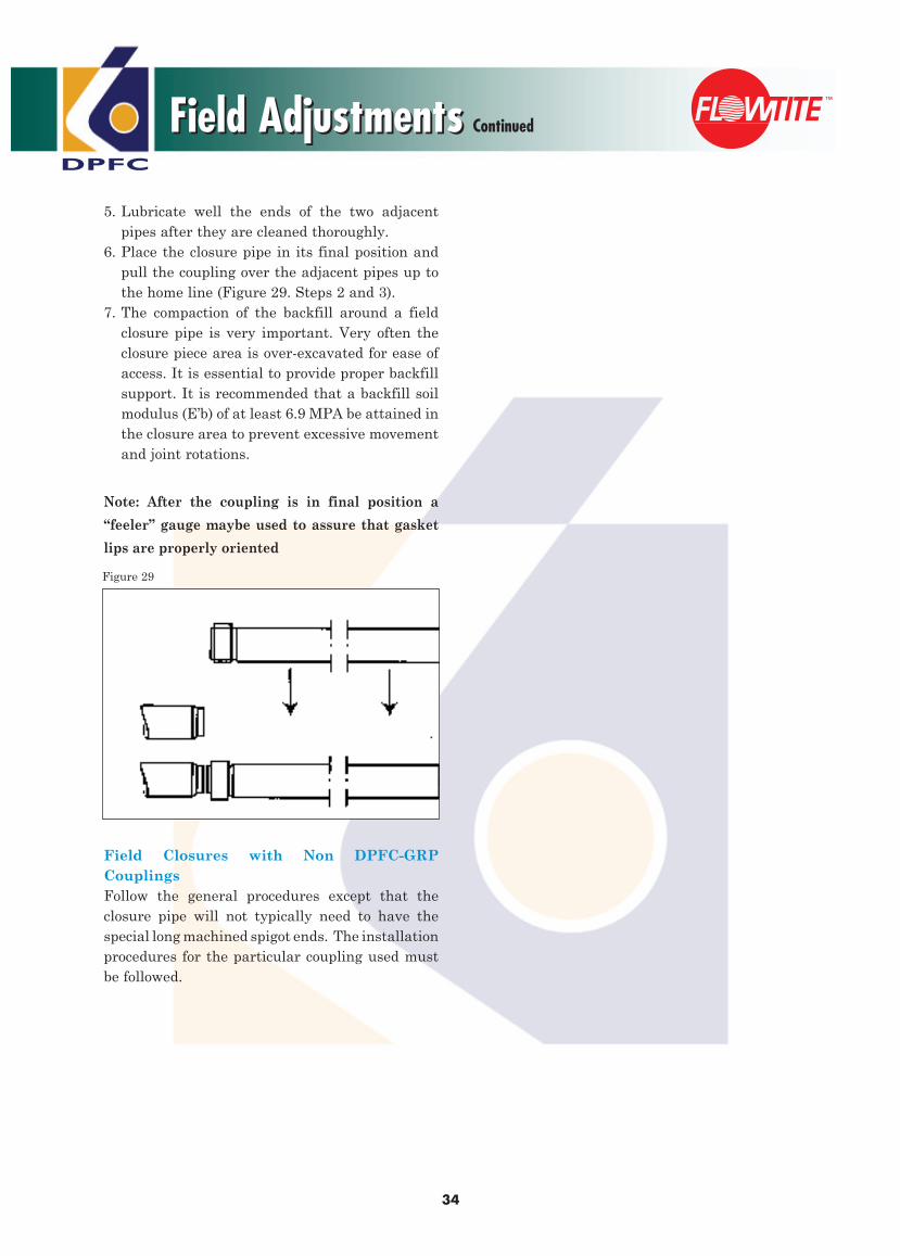
DPFC
34
5. Lubricate well the ends of the two adjacent pipes after they are cleaned thoroughly.6. Place the closure pipe in its final position and pull the coupling over the adjacent pipes up to the home line (Figure 29. Steps 2 and 3).7. The compaction of the backfill around a field closure pipe is very important. Very often the closure piece area is over-excavated for ease of access. It is essential to provide proper backfill support. It is recommended that a backfill soil modulus (E’b) of at least 6.9 MPA be attained in the closure area to prevent excessive movement and joint rotations.
Note: After the coupling is in final position a
“feeler” gauge maybe used to assure that gasket
lips are properly oriented
Field Closures with Non DPFC-GRP CouplingsFollow the general procedures except that the closure pipe will not typically need to have the special long machined spigot ends. The installation procedures for the particular coupling used must be followed.
Field AdjustmentsField Adjustments Continued
Figure 29

DPFC
35
Small Diameter Pipes (SDP) GRP PipesSmall Diameter Pipes (SDP) GRP Pipes
Small Diameter Pipes ranging from DN80 to DN300 mm are manufactured in our second production line using Dual Helical Winding process.
Manufacturing Process
Pipe
The Dual Helical Winding Process uses continuous Glass-fiber Filaments impregnated in resin. In this process the fiber glass roving wetted with resin is wound on the steel mandrel at pre-calculated winding angles (in reference to the axis of the mandrel vary from 50-90 Deg.). The dual helical winding pattern is responsible for providing the composite product with maximum mechanical durability. The resin used will decide the extent of its chemical and temperature resistance. The entire process is controlled via the software in which we determine the winding angles as well as the number of layers to be wound on to the product. Silica Sand if used is added during the winding process in the structural wall of the pipe to give necessary compressive strength if required. The dual Helical winding process is illustrated in Figure 1 and Figure 2.
Figure 1

36
DPFC
Small Diameter Pipes (SDP) GRP PipesSmall Diameter Pipes (SDP) GRP Pipes Continued
Load Capacity Values:For design purposes the following values can be used for hoop tensile and axial tensile load capacity.
Axial Tensile Load Capacity:Minimum initial load as shown intable 27.
Hoop Tensile Load Capacity:Minimum initial load as shown intable 26.
Hoop Tensile Load Capacity(N per mm of Length)
DN PN1-PN6 PN10 PN12 PN1680 92 153 183 244
100 122 203 244 325150 183 305 366 487200 244 406 487 650250 305 508 609 812300 366 609 731 975
Axial Tensile Load Capacity(N per mm of Circumference)
DN PN1-PN6 PN10 PN12 PN1680 75 80 85 90
100 75 80 85 90150 85 100 105 110200 95 110 115 120250 105 125 130 135300 115 140 145 150
Product Range - Pipes & Fittings:
Diameter DN (mm)
Pressure Class PN
(Bars)
Stiffness SN (N/m2)
80100 6 2,500150 10 5,000200 12 10,000250 16 300
Pipes with different pressure classes and stiffness could be manufactured depending on client’s requirement.Technical Details:Dimensions & Weight:
Nominal Diameter
Spigot OuterDiameter
Helical pipes with no fillerPIPE COUPLING
DNDOSMax(mm)
DOSMin
(mm)
Std. Pipe Length
(m)
Min. Pipe Thickness
(m)
Weight* (Kg/m)
Std. Coupling
Length (m)
Weight* (Kg/unit)
80 88 87 6 4.7 2.5 150 3
100 108 107 10 4.7 3 150 3.5
150 158.5 157.5 10 4.7 4.5 150 4.5
200 211 210 12 5.5 7 176 7
250 263.5 262.5 12 6.3 10 176 9
300 314.5 313.5 12 6.3 12 216 10
Figure 2
Table 24
Table 25
Table 26
Table 27

DPFC
Environmental Guide for DPFC Pipe
37
Acetic Acid <20% XAdipic Acid XAlum (Aluminium Potassium Sulfate) XAluminium Chloride, Aqueous XAmmonia, Aqueous <20% XAmmonium Chloride, Aqueous (40 °C) XAmmonium Flouride XAmmonium Nitrate, Aqueous (40 °C) XAmmonium Phosphate-Monobasic, Aqueous XAmmonium Sulfate, Aqueous XAniline Hydrochloride XAntimony Trichloride XBarium Carbonate XBarium Chloride XBarium Sulfate XBeet Sugar Liquor XBenzene Sulfonic Acid (10%)* XBenzoic Acid* XBlack Liquor (Paper) XBleach XBorax XBoric Acid XBromine, Aqueous 5%* XButyric Acid, <25% (40 °C)** XCalcium Bisulfide ** XCalcium Carbonate XCalcium Chlorate, Aqueous (40 °C) XCalcium Chloride (Saturated) XCalcium Hydroxide, 100% XCalcium Hypochlorite* XCalcium Nitrate (40 °C) XCalcium Sulfate NL AOC XCane Sugar Liquors XCarbon Dioxide, Aqueous X Carbon Tetrachloride XCasein XCaustic Potash (KOH) XChlorine, Dry Gas* XChlorine, Water * XChlorine, Wet Gas* XChlorocetic Acid XCitric Acid, Aqueous (40 °C) X
Environmental Guide for DPFC Pipe
Using this environment guide :All materials listed in “green” can be used with our current standard pipe resin systems as well as vinyl ester lined pipes. All materials listed in “blue” are in addition to the “green” materials that can be used in pipes that use a vinyl ester resin liner. All materials listed in “red” are not recommended and may not work in any type of DPFC-GRP pipe system.
Copper Acetate, Aqueous (40 °C) XCopper Chloride, Aqueous XCopper Cyanide (30 0C) XCopper Nitrate, Aqueous (40 °C) XCopper Sulfate, Aqueous (40 °C) XCrude Oil (Sour)* XCrude Oil (Sweet)* XCrude Oil, Salt Water (25 °C)* XCyclohexane XCyclohexanol XDibutyl Sebacate** XDibutylpthalate** XDiesel Fuel* XDioctyl Phthalate** XEthylene Glycol X Ferric Chloride, Aqueous XFerric Nitrate, Aqueous XFerric Sulfate, Aqueous XFerrous Chloride XFerrous Nitrate, Aqueous** XFerrous Sulfate, Aqueous XFormaldehyde XFuel Oil* XGas, Natural, Methane XGasoline, Ethyl* XGlycerine XGreen Liquor, Paper XHexane* XHydrobromic Acid XHydrochloric Acid, Up to 15% XHydrofluoric Acid XHydrogen Sulfide, Dry XKerosene* XLactic Acid, 10% XLactic Acid, 80% (25 °C) XLauric Acid XLauryl Chloride XLauryl Sulfate** XLead Acetate, Aqueous XLead Nitrate, Aqueous (30 °C) XLead Sulfate XLinseed Oil* X
Standard Pipe Resin Vinyl or Vinyl Ester Ester Only NR
Standard Pipe Resin Vinyl or Vinyl Ester Ester Only NR

DPFC
38
Lithium Bromide, Aqueous (40 °C)** XLithium Chloride, Aqueous (40 °C)** XMagnesium Bicarbonate, Aqueous (40 °C) XMagnesium Carbonate (40 °C) XMagnesium Chloride, Aqueous (25 °C) XMagnesium Nitrate, Aqueous (40 °C) XMagnesium Sulfate XManganese Chloride, Aqueous (40 °C)** XManganese Sulfate, Aqueous (40 °C)** XMercuric Chloride, Aqueous** XMercurous Chloride, Aqueous XMineral Oils* Xn-Heptane* XNaphthalene* XNaptha* XNickel Chloride, Aqueous (25 °C) XNickel Nitrate, Aqueous (40 °C) XNickel Sulfate, Aqueous (40 °C) XNitric Acid XOleic Acid XOxalic Acid, Aqueous XOzone, Gas XParaffin* XPentane XPerchloric Acid XPetroleum, Refined & Sour* XPhosphoric Acid XPhosphoric Acid (40 °C) XPhthalic Acid (25 °C) XPotassium Permanganate, 25% XPotassium Bicarbonate** XPotassium Bromide, Aqueous (40 °C) XPotassium Chloride, Aqueous XPotassium Dichromate, Aqueous XPotassium Ferrocyanide (30 °C)** XPotassium Ferrocyanide Aqueous (30 °C)** XPotassium Nitrate, Aqueous XPotassium Sulfate (40 °C) XPropylene Glycol (25 °C) XSea Water XSewage (50 °C) XSilicone Oil XSilver Nitrate, Aqueous XSodium Bromide, Aqueous XSodium Chloride, Aqueous XSodium Dichromate XSodium Dihydrogen Phosphate ** X
Sodium Ferrocyanide XSodium Hydroxide 10% XSodium Mono-Phosphate** XSodium Nitrate, Aqueous XSodium Nitrite, Aqueous XSodium Silicate XSodium Sulfate, Aqueous XSodium Sulfide XSodium Tetraborate XStannic Chloride, Aqueous* XStannous Chloride, Aqueous XStearic Acid* XSulfur XSulfuric Acid, <25% (40 °C) XTannic Acid, Aqueous XTartaric Acid XToluene Sulfonic Acid** XTributyl Phosphate XTriethanolamine XTriethylamine XTurpentine XUrea, (Aqueous)** XVinegar XWater, Distilled XWater, Sea XWater, Tap XZinc Chloride, Aqueous XZinc Nitrate, Aqueous** XZinc Sulfate, Aqueous XZinc Sulfite, Aqueous (40 °C)** X
Note : This guide is intended to serve as a basic guide when considering GRP pipe. Final determination of the suitability of a particular resin system for a given environment is the responsibility of the customer. This list is based on information supplied by resin manufacturers who provide Flowtite producers with their material. Thus this guide provides only general information and does not imply approval of any application as DPFC has no control of the conditions of usage nor any means of identifying environments to which the pipe may unintentionally have been exposed.
Standard Pipe Resin Vinyl or Vinyl Ester Ester Only NR
Standard Pipe Resin Vinyl or Vinyl Ester Ester Only NR
Environmental Guide for DPFC PipeEnvironmental Guide for DPFC Pipe Continued