
Cat. No. Z01E-EN-01
65
Cat. No. Z01E-EN-01 Vision Sensor with built-in touch screen Smart Sensor ZFX SHORT MANUAL
Transcript of Cat. No. Z01E-EN-01

Cat. No. Z01E-EN-01
Vision Sensor with built-in touch screen
Smart SensorZFX
SHORT MANUAL
Cat. No. Z01E-EN-01 Note: Specifi cations subject to change without notice.
Authorized Distributor:
Printed in Europe
Cat. N
o. Z01E-EN-01
Sm
art Sensor ZFX
Vision Sensor w
ith built-in touch screenSH
OR
T MA
NU
AL

Z01E-EN-01+ZFX+SettingGuide.book Seite 1 Mittwoch, 13. Februar 2008 2:38 14
ZFXVision Sensor with built-in touch screenShort ManualVer. 1.0, January 2008

Z01E-EN-01+ZFX+SettingGuide.book Seite 2 Mittwoch, 13. Februar 2008 2:38 14
TABLE OF CONTENTS
Z01E-EN-01+ZFX+SettingGuide.book Seite 3 Mittwoch, 13. Februar 2008 2:38 14
SECTION 1Preparation . . . . . . . . . . . . . . . . . . . . . . . . . . . . . . . . . . . . . . . 5
1-1 System Overview. . . . . . . . . . . . . . . . . . . . . . . . . . . . . . . . . . . . . . . . . . . . . . . . . . . . . . . . . . 51-2 Connecting the Devices . . . . . . . . . . . . . . . . . . . . . . . . . . . . . . . . . . . . . . . . . . . . . . . . . . . . . 61-3 Installing the Controller. . . . . . . . . . . . . . . . . . . . . . . . . . . . . . . . . . . . . . . . . . . . . . . . . . . . . 81-4 Installing the Intelligent Cameras . . . . . . . . . . . . . . . . . . . . . . . . . . . . . . . . . . . . . . . . . . . . . 101-5 Installing the C-mount Cameras . . . . . . . . . . . . . . . . . . . . . . . . . . . . . . . . . . . . . . . . . . . . . . 121-6 Installing the External Lightings (Only For ZFX-SC50/SC90) . . . . . . . . . . . . . . . . . . . . . . 141-7 Installing the External Lightings (Only For C-mount Camera (ZFX-S/SC)) . . . . . . . . . . . . 15
SECTION 2Main Operation. . . . . . . . . . . . . . . . . . . . . . . . . . . . . . . . . . . . 17
2-1 Operation Mode . . . . . . . . . . . . . . . . . . . . . . . . . . . . . . . . . . . . . . . . . . . . . . . . . . . . . . . . . . . 172-2 Adjusting the brightness of image . . . . . . . . . . . . . . . . . . . . . . . . . . . . . . . . . . . . . . . . . . . . . 182-3 Measurement Setting Example (Pattern Search) . . . . . . . . . . . . . . . . . . . . . . . . . . . . . . . . . . 202-4 Position Correction . . . . . . . . . . . . . . . . . . . . . . . . . . . . . . . . . . . . . . . . . . . . . . . . . . . . . . . . 222-5 Getting the clear image . . . . . . . . . . . . . . . . . . . . . . . . . . . . . . . . . . . . . . . . . . . . . . . . . . . . . 242-6 Changing the Display Information (ADJ/RUN Mode) . . . . . . . . . . . . . . . . . . . . . . . . . . . . . 302-7 Re-measuring the saved image (ADJ Mode). . . . . . . . . . . . . . . . . . . . . . . . . . . . . . . . . . . . . 31
SECTION 3Run-Mode Measurement Process . . . . . . . . . . . . . . . . . . . . . 33
SECTION 4Item Overview . . . . . . . . . . . . . . . . . . . . . . . . . . . . . . . . . . . . . 41
4-1 ITEM Overview (Pattern Search) . . . . . . . . . . . . . . . . . . . . . . . . . . . . . . . . . . . . . . . . . . . . . 414-2 ITEM Overview (Sensitive Search). . . . . . . . . . . . . . . . . . . . . . . . . . . . . . . . . . . . . . . . . . . . 434-3 ITEM Overview (Flexible Search) . . . . . . . . . . . . . . . . . . . . . . . . . . . . . . . . . . . . . . . . . . . . 444-4 ITEM Overview (Graphic Search) . . . . . . . . . . . . . . . . . . . . . . . . . . . . . . . . . . . . . . . . . . . . 454-5 ITEM overview (Area) . . . . . . . . . . . . . . . . . . . . . . . . . . . . . . . . . . . . . . . . . . . . . . . . . . . . . 464-6 ITEM Overview (Labeling). . . . . . . . . . . . . . . . . . . . . . . . . . . . . . . . . . . . . . . . . . . . . . . . . . 474-7 ITEM Overview (Position) . . . . . . . . . . . . . . . . . . . . . . . . . . . . . . . . . . . . . . . . . . . . . . . . . . 494-8 ITEM Overview (Width) . . . . . . . . . . . . . . . . . . . . . . . . . . . . . . . . . . . . . . . . . . . . . . . . . . . . 514-9 ITEM Overview (Count) . . . . . . . . . . . . . . . . . . . . . . . . . . . . . . . . . . . . . . . . . . . . . . . . . . . . 524-10 ITEM Overview (Angle) . . . . . . . . . . . . . . . . . . . . . . . . . . . . . . . . . . . . . . . . . . . . . . . . . . . . 534-11 ITEM Overview (Bright). . . . . . . . . . . . . . . . . . . . . . . . . . . . . . . . . . . . . . . . . . . . . . . . . . . . 544-12 ITEM Overview (HUE). . . . . . . . . . . . . . . . . . . . . . . . . . . . . . . . . . . . . . . . . . . . . . . . . . . . . 554-13 ITEM Overview (Defect) . . . . . . . . . . . . . . . . . . . . . . . . . . . . . . . . . . . . . . . . . . . . . . . . . . . 564-14 ITEM Overview (Grouping) . . . . . . . . . . . . . . . . . . . . . . . . . . . . . . . . . . . . . . . . . . . . . . . . . 58
3

Z01E-EN-01+ZFX+SettingGuide.book Seite 4 Mittwoch, 13. Februar 2008 2:38 14
SECTION 5Appendices. . . . . . . . . . . . . . . . . . . . . . . . . . . . . . . . . . . . . . . . 59
5-1 What is decided by AUTO setting. . . . . . . . . . . . . . . . . . . . . . . . . . . . . . . . . . . . . . . . . . . . . 595-2 BANK and BANK-Group . . . . . . . . . . . . . . . . . . . . . . . . . . . . . . . . . . . . . . . . . . . . . . . . . . . 60
Revision History . . . . . . . . . . . . . . . . . . . . . . . . . . . . . . . . . . . 62
4

Z01E-EN-01+ZFX+SettingGuide.book Seite 5 Mittwoch, 13. Februar 2008 2:38 14
SECTION 1Preparation
1-1 System OverviewBasically, the ZFX-C is configured by the Controller and the camera.
Other external devices can be selected to be used in combination with theZFX-C according to the user’s specific requirements.
*1. The Touch Pen (ZFX-TP) is supplied with the Controller.
*2. The same image as in the Controller's LCD monitor can be displayed in theLCD monitor (option).
*3. The console can be used instead of the Controller's keys and menu but-tons.
*4. Conforms to the SD Card “Physical layer specifications 1.01.” File format: FAT16
*5. ZFX-C20/25b can be connected with 2 cameras.
LCD monitor (option)
USB
Parallel I/O cableZFX-VP
Touch pen(*1)
SD Card (*4)
FZ-M08 (*2)
Ethemet
PC
Console
ZFX-KP
(*3)
RS-232C cableZFX-XPT_A
RS-422 cableZFX-XPT_B
Cameras with lighting
- Color camera
Camera only
ControllerZFX-C10/15/20/25
A CCTV lens and light source will be required.
(cable built-in)
- Color camera
ZFX-SC90/SC90W
ZFX-SC150/SC150W
ZFX-SC10/SC50/SC50W
- Monochrome camera
ZFX-SR10/SR50
ZFX-SC
- Monochrome camera
Monitor cableFZ-VM
ZFX-VS/VSR
Camera cableZFX-S
(*5)
PLC
3 421
5
1-2 Connecting the Devices Preparation
Z01E-EN-01+ZFX+SettingGuide.book Seite 6 Mittwoch, 13. Februar 2008 2:38 14
1-2 Connecting the Devices
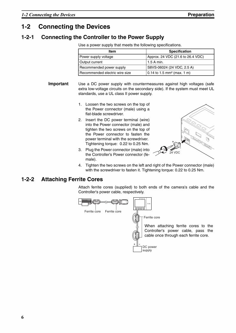
1-2-1 Connecting the Controller to the Power SupplyUse a power supply that meets the following specifications.
Important Use a DC power supply with countermeasures against high voltages (safeextra low-voltage circuits on the secondary side). If the system must meet ULstandards, use a UL class II power supply.
1. Loosen the two screws on the top ofthe Power connector (male) using aflat-blade screwdriver.
2. Insert the DC power terminal (wire)into the Power connector (male) andtighten the two screws on the top ofthe Power connector to fasten thepower terminal with the screwdriver.Tightening torque: 0.22 to 0.25 Nm.
3. Plug the Power connector (male) intothe Controller’s Power connector (fe-male).
4. Tighten the two screws on the left and right of the Power connector (male)with the screwdriver to fasten it. Tightening torque: 0.22 to 0.25 Nm.
1-2-2 Attaching Ferrite CoresAttach ferrite cores (supplied) to both ends of the camera's cable and theController's power cable, respectively.
Item Specification
Power supply voltage Approx. 24 VDC (21.6 to 26.4 VDC)
Output current 1.5 A min.
Recommended power supply S8VS-06024 (24 VDC, 2.5 A)
Recommended electric wire size 0.14 to 1.5 mm² (max. 1 m)
24 VDC
-
+
Ferrite coreFerrite core
+ -
Ferrite core
DC power supply
When attaching ferrite cores to theController's power cable, pass thecable once through each ferrite core.
6
1-2 Connecting the Devices Preparation
Z01E-EN-01+ZFX+SettingGuide.book Seite 7 Mittwoch, 13. Februar 2008 2:38 14
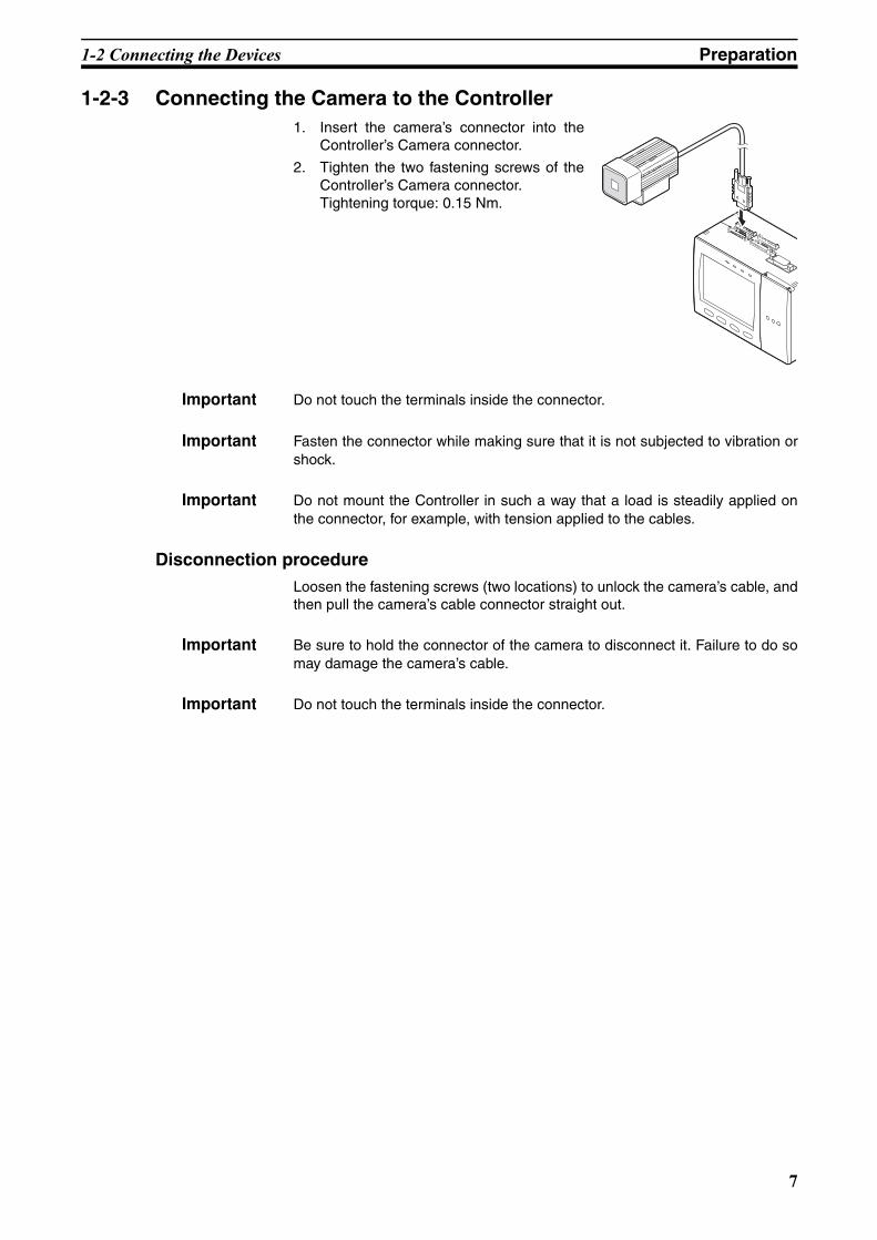
1-2-3 Connecting the Camera to the Controller1. Insert the camera’s connector into the
Controller’s Camera connector.
2. Tighten the two fastening screws of theController’s Camera connector.Tightening torque: 0.15 Nm.
Important Do not touch the terminals inside the connector.
Important Fasten the connector while making sure that it is not subjected to vibration orshock.
Important Do not mount the Controller in such a way that a load is steadily applied onthe connector, for example, with tension applied to the cables.
Disconnection procedureLoosen the fastening screws (two locations) to unlock the camera’s cable, andthen pull the camera’s cable connector straight out.
Important Be sure to hold the connector of the camera to disconnect it. Failure to do somay damage the camera’s cable.
Important Do not touch the terminals inside the connector.
7

1-3 Installing the Controller Preparation
Z01E-EN-01+ZFX+SettingGuide.book Seite 8 Mittwoch, 13. Februar 2008 2:38 14
1-3 Installing the Controller
1-3-1 Installation PrecautionsTo improve heat radiation, install the Controller only in the orientation showbelow.
Important Install the Controller so that the distance between the Controller and otherdevices is at least the dimensions shown in the figure below to improve theventilation.
Important Keep the ambient temperature less than 50 °C. If the ambient temperature ishigher than 50 °C, install a fan forced cooling system or an air conditioner tokeep the temperature lower than 50 °C.
Important Avoid mounting on a panel, in which high-voltage emitting devices areinstalled to prevent ZFX-C operation from being affected by noise.
Important Allow at least 10 m between the Controller and power lines to keep noise at alow level in the operating environment.
1-3-2 Installing on the DIN Track1. Hook the Controller’s upper hook onto the
DIN track.
2. Push the Controller down onto the DIN trackuntil its lower hook is snapped into place.
Important Attach the End Plate (sold separately) to both sides of the Controller on theDIN track.
Right
Upward
Wrong Wrong
Min. 50 mm
Min. 15 mm
When installing Controller only: When installing the Controller With the Exhaust Unit attached:
Min. 50 mm
Min. 15 mm
1
2
8

1-3 Installing the Controller Preparation
Z01E-EN-01+ZFX+SettingGuide.book Seite 9 Mittwoch, 13. Februar 2008 2:38 14
Important Attach the Exhaust Unit (supplied) to the Controller when installing otherdevices adjacently on the same DIN track as the Controller.
Removing procedure1. Pull the Controller’s lower hook downwards.
2. Lift up the Controller from its bottom to re-move it from the DIN track.
1-3-3 Mounting on the Panel1. Install the long Panel Mount
Adapters on the four holes on theController.
2. Install the short Panel MountAdapters on the two holes on thelong Panel Mount Adapter.
3. Install the Controller with MountAdapters attached onto the panelfrom the front.
4. Hook the hooks of the mountingbracket onto the two holes (twoeach at top and bottom) of thelonger Mount Adapters and tight-en the screws. Tightening torque: 1.2 N•m.
5. Make sure that the Controller isfirmly fixed on the panel.
PULL OPEN
1 2 3 4
OMRONZFX-C10 OUTPUT RUN ERROR ENABLE
MENU RUN
SDCARD
ADJ
USB
AUTO ESC
SET
DIN track (sold separately)
End Plate (sold separately) PFP-M
PFP-100N (1 m)PFP-50N (0.5 m)PFP-100N2 (1 m)
Exhaust Unit
12
1
1
2
2
3
Panel mount adapters
Panel
4
Mounting bracket
9

1-4 Installing the Intelligent Cameras Preparation
Z01E-EN-01+ZFX+SettingGuide.book Seite 10 Mittwoch, 13. Februar 2008 2:38 14
1-4 Installing the Intelligent Cameras
1-4-1 Optical chart
Note • The lens has a fixed focal point. The actual detection range and focal pointvary from lens to lens, so adjust the distance to the measurement targetafter replacing the lens or camera.
• The camera mounting distance listed in the following tables is an approxi-mate value. Mount the Camera so that the distance to the measurementtarget can be adjusted easily.
• If the object size and detection range are incompatible, use a combinationof a camera (without lighting), standard CCTV lens and light source.
ZFX-SC10/SR10
Setting distance (L)
Detection range (H) 8.9
104
4.9
0
34
4950
60
Setting distance L (mm)
Detection range H (mm)
ZFX-SR50 ZFX-SC50/SC50W
99.8 49
6030
38
100
194
300
Setting distance L (mm)
Detection range H (mm)
100
9.8
3031
187190
49
Setting distance L (mm)
Detection range H (mm)
ZFX-SC90/SC90W ZFX-SC150/SC150W
Setting distance L (mm)
Detection range H (mm)
7089
1004040
67
100
142
160
49
Setting distance L (mm)
Detection range H (mm)
100
148
16012080
115
180
227240
89
10

1-4 Installing the Intelligent Cameras Preparation
Z01E-EN-01+ZFX+SettingGuide.book Seite 11 Mittwoch, 13. Februar 2008 2:38 14
1-4-2 Installing the mounting fixtureThe mounting fixture can be installed on all of the four mounting surfaces.
1. Align the two hooks on one side ofthe mounting fixture with the twogrooves on the camera body.
2. Push the other hook down until itis snapped into place.Make sure that the mounting fix-ture is firmly fixed on the camera.
3. Fasten the mounting fixture at themounting location with screws.Tightening torqueM4: 1.2 Nm1/4”-20 UNC: 2.6 Nm
Removal procedure1. Insert a screwdriver into the gap
(one of the two gaps) between themounting fixture and the cameracase, and remove the mountingfixture.
1-4-3 Adjusting the camera focus1. Adjust the distance between the
camera and the measurement tar-get and fasten the camera.Refer to the optical chart and setthe camera in a position so thatthe area to be checked is withinthe detection area (LCD monitor).
“Optical chart” p. 10.
2. Turn the focus adjustment controlto the left and right to adjust thefocus.
Note First turn the focus adjustment control slightly to the left and right, to makesure that the Focus adjustment control is not at the upper or lower limit posi-tions. Do not exert unnecessary force to turn the control at the upper or lowerlimit positions as this might damage the control.(For ZFX-SC90_/SC150_, the control stops turning at the nearest position. Itturns free at the farthest position.)
Hooks
Grooves on camera
Mounting fixture
Mounting fixture
Setting distance (L)
Detection range (H)
Focus adjustment control
11

1-5 Installing the C-mount Cameras Preparation
Z01E-EN-01+ZFX+SettingGuide.book Seite 12 Mittwoch, 13. Februar 2008 2:38 14
1-5 Installing the C-mount Cameras
1-5-1 Optical chartThe values in the following chart are approximations, and the Camera must beadjusted after it is mounted.
The X axis of the optical chart shows detection range L (mm), and the Y axisshows the camera distance A (mm). The curves on the optical chart show therelationship between the detection range and camera distance for each CCTVlens. The values are significantly different for each lens, so double-check themodel of the lens before using the graph. The “t” values indicate the lengths ofthe Extension Tubes. The value “t0” shows the case where an Extension Tube
40
100
1000
10000
4 10 100 1000Detection range(mm)
Detection range(mm)
ML-0614
ML-0813
ML-1214
ML-1614
ML-2514ML-3519
ML-5018
Lens model3Z4S-LE
Lens model3Z4S-LE
Cam
era
dist
ance
A(m
m)
Cam
era
dist
ance
A(m
m)
200
1000
10000
2 10 100 1000
t2
t5t10
t15t20
t30t35t50
t45
t5
t10t15t20t25t30t40 t35
t45t50
t60
t0
t2
t40t25
t0ML-7527
ML-10035
t: Extension tube
Examplet0: Extension tube
is not required.t5: 5-mm extension
tube is required.
12

1-5 Installing the C-mount Cameras Preparation
Z01E-EN-01+ZFX+SettingGuide.book Seite 13 Mittwoch, 13. Februar 2008 2:38 14
is not required and the value “t5.0” shows the case where a 5-mm ExtensionTube is used.
Example
When a 3Z4S-LE ML-5018 CCTV Lens is being used and a detection range of40 mm is required at the measurement target, a camera distance of 500 mmand 5-mm Extension Tube are required.
1-5-2 Installing the Camera Mounting BaseThe camera mounting base mounted on the bottom of the camera can beinstalled on all of the four mounting surfaces. To change the mounting surface,remove the three mounting screws (M2 x 6) from the camera.
• Tightening torque when fastening the camera mounting base at themounting locationM4: 1.2 Nm1/4”-20 UNC: 2.6 Nm
Extension Tube t_ (mm)
Camera
Lens
Measurement object
Camera distance A (mm)
Detection range L (mm)
Camera Mounting Base
13
1-6 Installing the External Lightings (Only For ZFX-SC50/SC90) Preparation
Z01E-EN-01+ZFX+SettingGuide.book Seite 14 Mittwoch, 13. Februar 2008 2:38 14
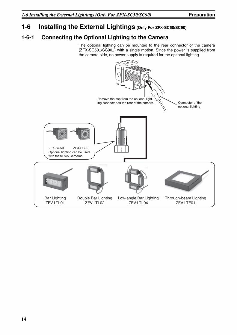
1-6 Installing the External Lightings (Only For ZFX-SC50/SC90)
1-6-1 Connecting the Optional Lighting to the CameraThe optional lighting can be mounted to the rear connector of the camera(ZFX-SC50_/SC90_) with a single motion. Since the power is supplied fromthe camera side, no power supply is required for the optional lighting.
Remove the cap from the optional light-ing connector on the rear of the camera. Connector of the
optional lighting
ZFX-SC50 ZFX-SC90Optional lighting can be used with these two Cameras.
Bar LightingZFV-LTL01
Double Bar LightingZFV-LTL02
Low-angle Bar LightingZFV-LTL04
Through-beam LightingZFV-LTF01
14
1-7 Installing the External Lightings (Only For C-mount Camera (ZFX-S/SC)) Preparation
Z01E-EN-01+ZFX+SettingGuide.book Seite 15 Mittwoch, 13. Februar 2008 2:38 14
1-7 Installing the External Lightings (Only For C-mount Camera (ZFX-S/SC))
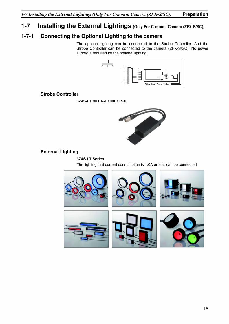
1-7-1 Connecting the Optional Lighting to the cameraThe optional lighting can be connected to the Strobe Controller. And theStrobe Controller can be connected to the camera (ZFX-S/SC). No powersupply is required for the optional lighting.
Strobe Controller 3Z4S-LT MLEK-C100E1TSX
External Lighting 3Z4S-LT Series
The lighting that current consumption is 1.0A or less can be connected
Strobe Controller
15

1-7 Installing the External Lightings (Only For C-mount Camera (ZFX-S/SC)) Preparation
Z01E-EN-01+ZFX+SettingGuide.book Seite 16 Mittwoch, 13. Februar 2008 2:38 14
16

Z01E-EN-01+ZFX+SettingGuide.book Seite 17 Mittwoch, 13. Februar 2008 2:38 14
SECTION 2Main Operation
2-1 Operation ModeThe ZFX-C has the following threemodes. Switch to the desired modebefore you start operation. To switchthe operation mode, use the modeswitch.
Mode Description
MENU mode This mode is for setting the measurement conditions. The easy-to-follow icon-based display allows opera-tions to be performed intu-itively.
ADJ mode This mode is for checking the measurement status and adjusting conditions. Mea-surement results are only displayed on the monitor and are not output.
ImportantTrigger input isn’t acceptable
RUN mode This mode is used for per-forming actual measure-ment. Measurement results are displayed on the moni-tor and output.
ImportantMeasurement trigger by menu operation is to push [SET]-key & [UP]-key
ADJADJMENUMENU RUNRUN
Mode switch
SetupTool SystemBank Save
Top menu
TEA
LIVE
Top Screen
Previous Next Dsplay SW Adjust
Individual result
TEA
Camera 00.Bank00 0.Pattern Search
Judge OKCorrelation 92Position X 462Position Y 352Angle 15
OK 353ms
Top Screen
Previous Next Dsplay SW Capture
Individual result
TEA
Camera 00.Bank00 0.Pattern Search
Judge OKCorrelation 92Position X 462Position Y 352Angle 15
OK 353ms
Top Screen
17
2-2 Adjusting the brightness of image Main Operation
Z01E-EN-01+ZFX+SettingGuide.book Seite 18 Mittwoch, 13. Februar 2008 2:38 14
2-2 Adjusting the brightness of image
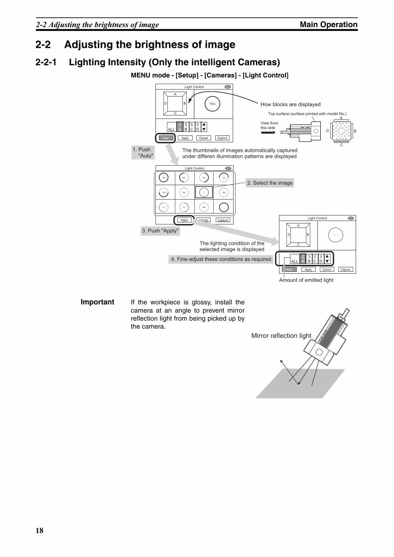
2-2-1 Lighting Intensity (Only the intelligent Cameras)MENU mode - [Setup] - [Cameras] - [Light Control]
Important If the workpiece is glossy, install thecamera at an angle to prevent mirrorreflection light from being picked up bythe camera.
A
5AALL
5B
5C
C
D B
Auto CancelApply Capture
SDLight Control
TEA
5D
A
D
C
B
TEA TEA TEA TEA
TEA TEA TEA TEA
TEA TEA TEA
Capture
SDLight Control
CancelApply
Auto Apply Cancel Capture
D
A
C
ALL
SDLight Control
TEAB
2A
3B
2C
3D
Auto
How blocks are displayed
The thumbnails of images automatically captured under differen illumination patterns are displayed
The lighting condition of the selected image is displayed
Amount of emitted light
Top surface (surface printed with model No.)
View from this side
4. Fine-adjust these conditions as required.
3. Push "Apply"
2. Select the image
1. Push "Auto"
Mirror reflection light
18

2-2 Adjusting the brightness of image Main Operation
Z01E-EN-01+ZFX+SettingGuide.book Seite 19 Mittwoch, 13. Februar 2008 2:38 14
2-2-2 Shutter SpeedSet the shutter speed to match the speed of movement of the measurementtarget and the lighting environment.
MENU mode - [Setup] - [Cameras] - [Shutter Speed]
Note Guidelines for setting shutter speedShutter speed characteristics are as follows. Select the appropriate shutterspeed to suit your inspection requirements.
2-2-3 Gain SettingThe sensor's gain (sensitivity) can be adjusted if bright images cannot beobtained just by the Shutter Speed and Light Control settings.
MENU mode - [Setup] - [Cameras] - [Gain]
Note Guidelines for setting gainIncreasing the gains results in a brighter image, however, the noise compo-nent contained in the image also becomes more conspicuous. Select theappropriate gain factor to suit your inspection requirements.
Setting value Description
1/170 to 1/20000 s Fixes the shutter speed to the desired value. Only available candidate shutter speeds are displayed. The candidates dif-fer with the camera that is connected and setup conditions.
Shutter Speed Speed of Movement of Measurement Target
1/170 s
•1/20000 s
Slow
•Fast
Setting value Description
x 1.0, x 1.5, x 2.0 Sets the gain factor.x 1.0: The gain factor is not changed. (default value)
x 1.5: The gain factor is set to 1.5X.
x 2.0: The gain factor is set to 2.0X.
Gain Image Image Quality
x 1.0
•x 2.0
Dark
↑ ↓Bright
Good (little noise)
↑ ↓Coarse (conspicuous noise)
19
2-3 Measurement Setting Example (Pattern Search) Main Operation
Z01E-EN-01+ZFX+SettingGuide.book Seite 20 Mittwoch, 13. Februar 2008 2:38 14
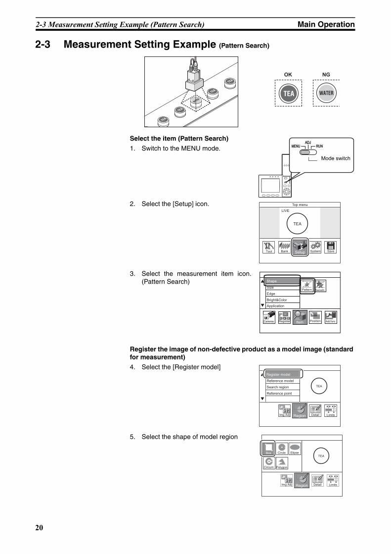
2-3 Measurement Setting Example (Pattern Search)
Select the item (Pattern Search)
1. Switch to the MENU mode.
2. Select the [Setup] icon.
3. Select the measurement item icon.(Pattern Search)
Register the image of non-defective product as a model image (standard for measurement)
4. Select the [Register model]
5. Select the shape of model region
OK NG
ADJADJMENUMENU RUNRUN
Mode switch
SetupTool SystemBank Save
Top menu
TEA
LIVE
Shape
Size
Edge
Bright&Color
Application
ItemRegister Position Add funcCameras
Pattern Sensiti.
Inspect
Register model
Reference model
Search region
Reference point
TEA
RegionImg Adj Detail Limits
Inspect
TEA
RegionImg Adj Detail Limits
Circle Elipse
Circum Polygon
Box
20
2-3 Measurement Setting Example (Pattern Search) Main Operation
Z01E-EN-01+ZFX+SettingGuide.book Seite 21 Mittwoch, 13. Februar 2008 2:38 14
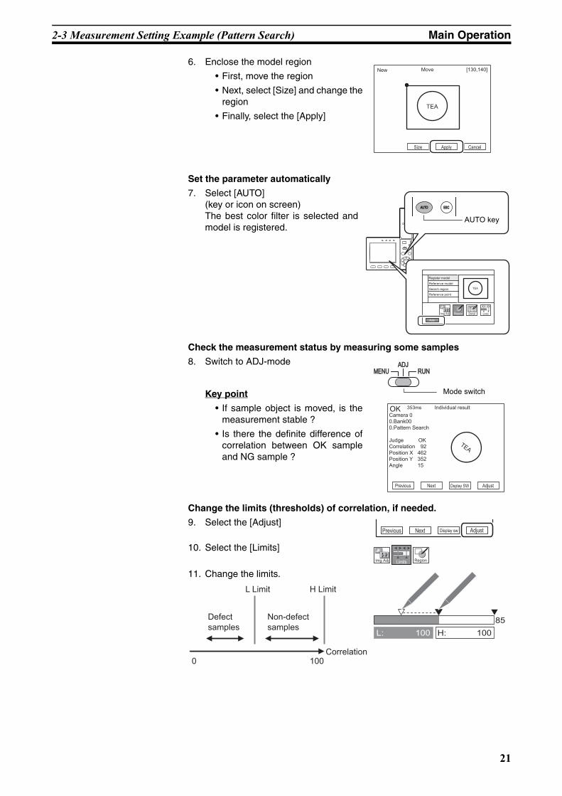
6. Enclose the model region
• First, move the region
• Next, select [Size] and change theregion
• Finally, select the [Apply]
Set the parameter automatically
7. Select [AUTO] (key or icon on screen)The best color filter is selected andmodel is registered.
Check the measurement status by measuring some samples
8. Switch to ADJ-mode
Key point
• If sample object is moved, is themeasurement stable ?
• Is there the definite difference ofcorrelation between OK sampleand NG sample ?
Change the limits (thresholds) of correlation, if needed.
9. Select the [Adjust]
10. Select the [Limits]
11. Change the limits.
TEA
Size Apply Cancel
New Move [130,140]
AUTOAUTO ESCESC
SET
Auto
Register model
Reference model
Search region
Reference point
TEA
RegionImg Adj Detail Limits
AUTO key
ADJADJMENUMENU RUNRUN
Previous Next Dsplay SW Adjust
Individual result
TEA
Camera 00.Bank00 0.Pattern Search
Judge OKCorrelation 92Position X 462Position Y 352Angle 15
OK 353ms
Mode switch
Previous Next Display sw Adjust
RegionImg Adj Limits
L: 100 H: 100
85Defect samples
Non-defect samples
Correlation1000
L Limit H Limit
21
2-4 Position Correction Main Operation
Z01E-EN-01+ZFX+SettingGuide.book Seite 22 Mittwoch, 13. Februar 2008 2:38 14
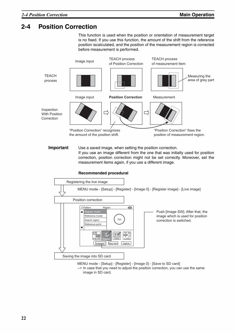
2-4 Position CorrectionThis function is used when the position or orientation of measurement targetis no fixed. If you use this function, the amount of the shift from the referenceposition iscalculated, and the position of the measurement region is correctedbefore measurement is performed.
Important Use a saved image, when setting the position correction.If you use an image different from the one that was initially used for positioncorrection, position correction might not be set correctly. Moreover, set themeasurement items again, if you use a different image.
Recommended procedural
TEACH
process
Image inputTEACH process
of measurement Item
Measuring the area of grey part
Image input Position Correction Measurement
TEACH process
of Position Correction
InspectionWith Position Correction
“Position Correction” recognizes the amount of the position shift.
“Position Correction” fixes the position of measurement region.
Inspect
Image sw Setup menu Capture
SDRegion0.Pattern
Register model
Reference model
Search region
Reference point
TEA
RegionImg Adj Detail Limits
Saving the image into SD card
Position correction
Registering the live image
Push [Image SW]. After that, the image which is used for position correction is switched.
MENU mode - [Setup] - [Register] - [Image 0] - [Register image] - [Live image]
MENU mode - [Setup] - [Register] - [Image 0] - [Save to SD card]--> In case that you need to adjust the position correction, you can use the same
image in SD card.
22

2-4 Position Correction Main Operation
Z01E-EN-01+ZFX+SettingGuide.book Seite 23 Mittwoch, 13. Februar 2008 2:38 14
Density changes.
Edge Position
Labeling
The position is detected by density changes and is corrected.
How to set is the same way of "Position"
How to set is the same way of "Labeling"
The image is binarized to detect the group (label) of the measurement target color to correct the position.
If the measurement target has a characteristic pattern, the position of that pattern is detected to correct the position.
2 modelTwo models are registered, and the position difference is corrected using the center coordinates of a straight line joining the two models and the angle of that line to the horizontal.
AreaThe image is binarized to detect the position of the measurement target color area to correct the position.
Image can be binarized.
1 model
High accuracy correction is needed.
Measurement target has a characteristic pattern.
Image can be binarized.
Measurement target is not at an angle.
Measurement target is at an angle.
Density changes.
AngleTwo positions are detected by density changes, and position difference is corrected using the center coordinates of a straight line joining these two positions.
Uneven density
Graphic SearchThe position of the pattern is detected and corrected using profile information. Measurement can be performed stably even when density is uneven.
How to set is the same way of "Pattern Search"
How to set is the same way of "Pattern Search"
How to set is the same way of "Area"
How to set is the same way of "Angle"
How to set is the same way of "Graphic Search"
23
2-5 Getting the clear image Main Operation
Z01E-EN-01+ZFX+SettingGuide.book Seite 24 Mittwoch, 13. Februar 2008 2:38 14
2-5 Getting the clear image
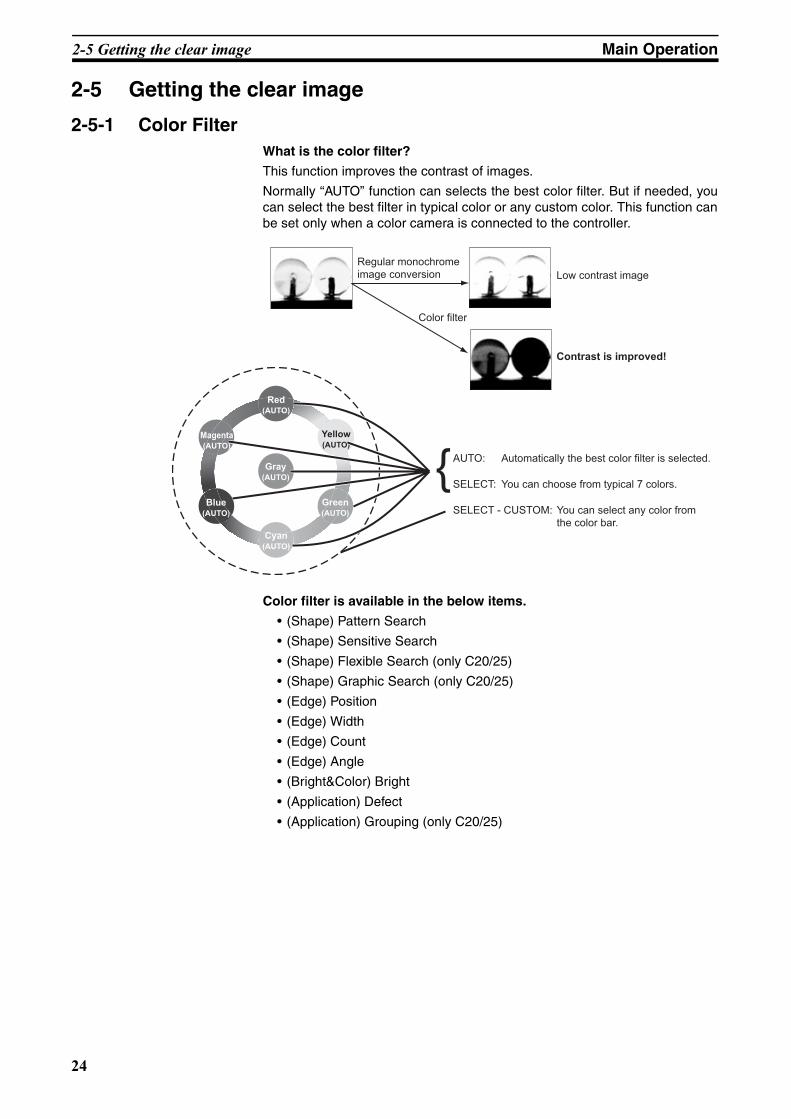
2-5-1 Color FilterWhat is the color filter?
This function improves the contrast of images.
Normally “AUTO” function can selects the best color filter. But if needed, youcan select the best filter in typical color or any custom color. This function canbe set only when a color camera is connected to the controller.
Color filter is available in the below items.
• (Shape) Pattern Search
• (Shape) Sensitive Search
• (Shape) Flexible Search (only C20/25)
• (Shape) Graphic Search (only C20/25)
• (Edge) Position
• (Edge) Width
• (Edge) Count
• (Edge) Angle
• (Bright&Color) Bright
• (Application) Defect
• (Application) Grouping (only C20/25)
Regular monochrome image conversion
Color filter
Low contrast image
Contrast is improved!
Red(AUTO)
Gray(AUTO)
Cyan(AUTO)
Green(AUTO)
Yellow(AUTO)
Blue(AUTO)
Magenta(AUTO)
AUTO: Automatically the best color filter is selected.
SELECT: You can choose from typical 7 colors.
SELECT - CUSTOM: You can select any color from the color bar.
{
24
2-5 Getting the clear image Main Operation
Z01E-EN-01+ZFX+SettingGuide.book Seite 25 Mittwoch, 13. Februar 2008 2:38 14
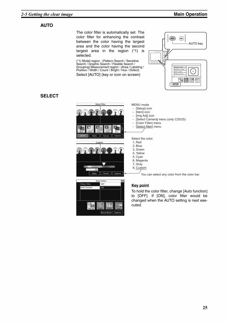
AUTOThe color filter is automatically set. Thecolor filter for enhancing the contrastbetween the color having the largestarea and the color having the secondlargest area in the region (*1) isselected.(*1) Model region : (Pattern Search / Sensitive Search / Graphic Search / Flexible Search / Grouping) Measurement region : (Area / Labeling / Position / Width / Count / Bright / Hue / Defect)
Select [AUTO] (key or icon on screen)
SELECT
Key point
To hold the color filter, change [Auto function]to [OFF]. If [ON], color filter would bechanged when the AUTO setting is next exe-cuted.
AUTOAUTO ESCESC
SET
Auto
Register model
Reference model
Search region
Reference point
TEA
RegionImg Adj Detail Limits
AUTO key
MENU mode - [Setup] icon - [Item] icon - [Img Adj] icon - [Select Camera] menu (only C20/25) - [Color Filter] menu - [Select filter] menu
Select the color. 1, Red 2, Blue 3, Green 4, Yellow 5, Cyan 6, Magenta 7, Gray 8, Custom
You can select any color from the color bar.
25

2-5 Getting the clear image Main Operation
Z01E-EN-01+ZFX+SettingGuide.book Seite 26 Mittwoch, 13. Februar 2008 2:38 14
2-5-2 Color PickupWhat is the color pickup?
This function is needed for image binarization (digitalization).After processingthe color pickup, camera image is converted into the binary image.
Up to 4 target colors can be specified for one measurement item.
This function can be set only when a color camera is connected to the control-ler. When a monochrome camera is connected, binary level can be set.
Color Pickup is available in the below items.
• (Size) Area
• (Size) Labeling (only C20/25)
• (Edge) Position *
• (Edge) Width *
• (Edge) Count *
• (Edge) Angle ** You can select the color pickup in [Detail] –[Color mode]
Hint of color pickup
Color has three parameters. You can adjust three parameters.
Parameter Description
Hue The name of a color, such as red, yellow or blue. Hue is expressed by a chromaticity diagram.
Saturation The degree to which color is mixed with white. When a color has little saturation, it becomes an achromatic color. The higher saturation becomes, the purer the color becomes in propor-tion to hue.
Brightness value The ratio of light intensity in a color.
0359
100 (white)
100 (vivid)
0 (black)
Brightness value
Saturation
Hue
0 (achromatic color)
Chromaticity diagram
26
2-5 Getting the clear image Main Operation
Z01E-EN-01+ZFX+SettingGuide.book Seite 27 Mittwoch, 13. Februar 2008 2:38 14
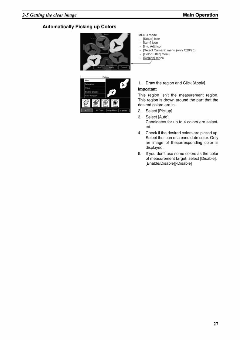
Automatically Picking up Colors
1. Draw the region and Click [Apply]
Important
This region isn’t the measurement region.This region is drown around the part that thedesired colore are in.
2. Select [Pickup]
3. Select [Auto]Candidates for up to 4 colors are select-ed.
4. Check if the desired colors are picked up.Select the icon of a candidate color. Onlyan image of thecorresponding color isdisplayed.
5. If you don’t use some colors as the colorof measurement target, select [Disable].[Enable/Disable][-Disable]
MENU mode - [Setup] icon - [Item] icon - [Img Adj] icon - [Select Camera] menu (only C20/25) - [Color Filter] menu - [Region] menu
27
2-5 Getting the clear image Main Operation
Z01E-EN-01+ZFX+SettingGuide.book Seite 28 Mittwoch, 13. Februar 2008 2:38 14
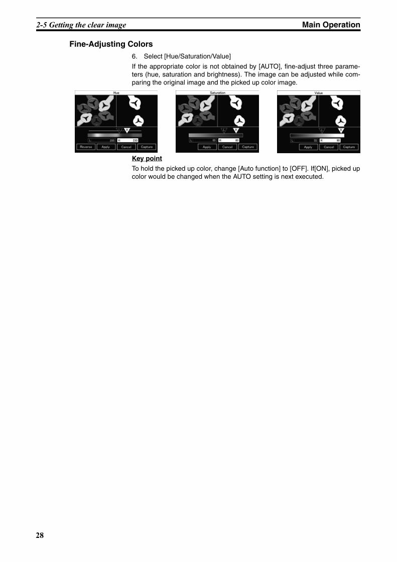
Fine-Adjusting Colors6. Select [Hue/Saturation/Value]
If the appropriate color is not obtained by [AUTO], fine-adjust three parame-ters (hue, saturation and brightness). The image can be adjusted while com-paring the original image and the picked up color image.
Key point
To hold the picked up color, change [Auto function] to [OFF]. If[ON], picked upcolor would be changed when the AUTO setting is next executed.
28

2-5 Getting the clear image Main Operation
Z01E-EN-01+ZFX+SettingGuide.book Seite 29 Mittwoch, 13. Februar 2008 2:38 14
2-5-3 Pre-processingWhat is the Pre-processing?
This function changes the camera image into the image which is easier tomeasure.
Important You can set the different pre-processing for each position correction and mea-surement item.
MENU mode - [Setup] - [Item] - [Img Adj] - [Select camera] - [Filtering]
Note Filter StrengthThe filter strength can be selected when applying the filtering options toimages. Each selection of the [5x5 filter]/[3x3 filter] in the filtering setup screentoggles the filter strength.
Filtering Target Image Description of Filtering
OFF (default value) - -
Smooth Measurement targets containing slightly unevenness
Creates a cloudy effect to soften the unevenness.
Erosion Black measurement targets containing white noise
Reduces the white component to eliminate the noise.
Dilation White measurement targets containing black noise
Spreads the white component to eliminate the black noise.
Median Measurement targets containing slightly unevenness
Softens the unevenness while keeping the image contour intact.
Sharpen Measurement targets containing fuzzy areas (fluctuating lighting, etc.)
Enhances the border lines between light and dark areas in the image.
V Edge Images that are difficult to pick up due to poor contrast
Picks up the vertical border lines (contrast) in the image.
H Edge Images that are difficult to pick up due to poor contrast
Picks up the horizontal border lines (contrast) in the image.
All Edge Images that are difficult to pick up due to poor contrast
Picks up all border lines (contrast) in the image.
Smooth
Median
H Edge
Erosion Dilation
V EdgeSharpen
All Edge
29
2-5 Getting the clear image Main Operation
Z01E-EN-01+ZFX+SettingGuide.book Seite 30 Mittwoch, 13. Februar 2008 2:38 14
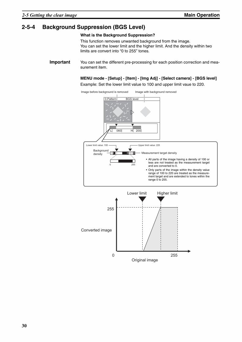
2-5-4 Background Suppression (BGS Level)What is the Background Suppression?
This function removes unwanted background from the image.You can set the lower limit and the higher limit. And the density within two limits are convert into “0 to 255” tones.
Important You can set the different pre-processing for each position correction and mea-surement item.
MENU mode - [Setup] - [Item] - [Img Adj] - [Select camera] - [BGS level]
Example: Set the lower limit value to 100 and upper limit vaue to 220.
L[ 060] H[ 200]
BGS level0.Pattern
Lower limit value: 100 Upper limit value: 220
Background density Measurement target density
0 255
Image before background is removed Image with background removed
• All parts of the image having a density of 100 orless are not treated as the measurement targetand are converted to 0.
• Only parts of the image within the density valuerange of 100 to 220 are treated as the measure-ment target and are extended to tones within therange 0 to 255.
Original image2550
255
Converted image
Lower limit Higher limit
30
2-6 Changing the Display Information (ADJ/RUN Mode) Main Operation
Z01E-EN-01+ZFX+SettingGuide.book Seite 31 Mittwoch, 13. Februar 2008 2:38 14
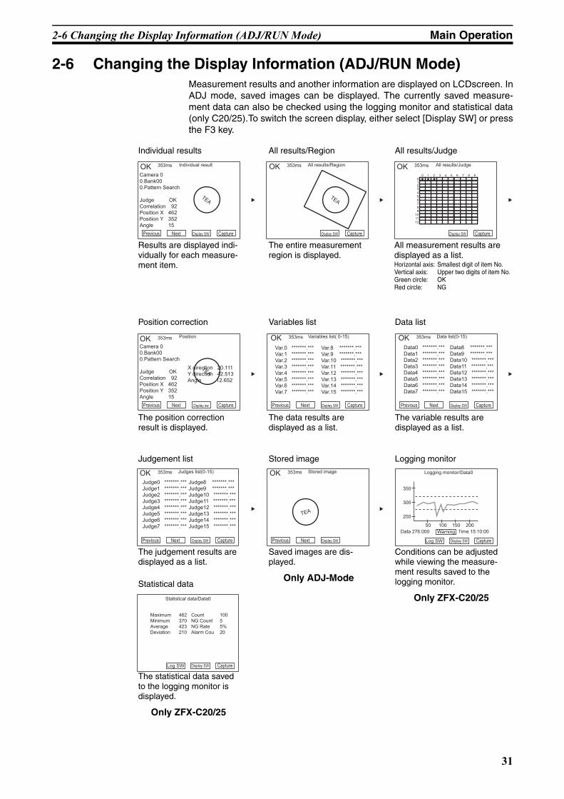
2-6 Changing the Display Information (ADJ/RUN Mode)Measurement results and another information are displayed on LCDscreen. InADJ mode, saved images can be displayed. The currently saved measure-ment data can also be checked using the logging monitor and statistical data(only C20/25).To switch the screen display, either select [Display SW] or pressthe F3 key.
Previous Next Dsplay SW Capture
Individual result
Camera 00.Bank00 0.Pattern Search
Judge OKCorrelation 92Position X 462Position Y 352Angle 15
TEA
Dsplay SW Capture
All results/Region
TEA
Dsplay SW Capture
All results/Judge
001234 5 6 7 8 9
10 11 12
1 2 3 4 5 6 7 8 9
OK 353ms OK 353ms OK 353ms
Previous Next Dsplay SW Capture
Data list(0-15)
Data0 *******.***Data1 *******.***Data2 *******.***Data3 *******.*** Data4 *******.***Data5 *******.***Data6 *******.***Data7 *******.***
Data8 *******.***Data9 *******.***Data10 *******.***Data11 *******.***Data12 *******.*** Data13 *******.***Data14 *******.***Data15 *******.***
Previous Next Dsplay sw Capture
Position
TEA
Camera 00.Bank00 0.Pattern Search
Judge OKCorrelation 92Position X 462Position Y 352Angle 15
X direction 20.111Y direction 42.513Angle 12.652
OK 353ms
Previous Next Dsplay SW Capture
Variables list( 0-15)
Var.0 *******.***Var.1 *******.***Var.2 *******.***Var.3 *******.*** Var.4 *******.***Var.5 *******.***Var.6 *******.***Var.7 *******.***
Var.8 *******.***Var.9 *******.***Var.10 *******.***Var.11 *******.***Var.12 *******.*** Var.13 *******.***Var.14 *******.***Var.15 *******.***
OK 353ms OK 353ms
TEA
Judge0 *******.***Judge1 *******.***Judge2 *******.***Judge3 *******.*** Judge4 *******.***Judge5 *******.***Judge6 *******.***Judge7 *******.***
Judge8 *******.***Judge9 *******.***Judge10 *******.***Judge11 *******.***Judge12 *******.*** Judge13 *******.***Judge14 *******.***Judge15 *******.***
Previous Next Dsplay SW Capture
Judges list(0-15)OK 353ms
Previous Next Dsplay SW
Stored imageOK 353ms
Log SW Display SW Capture
Logging monitor/Data0
Data 276.000 Time 15:10:00
250
300
350
Warning
50 100 150 200
Statistical data/Data0
Maximum 462Minimum 370Average 423Deviation 210
Count 100NG Count 5NG Rate 5%Alarm Cou 20
Log SW Display SW Capture
Individual results All results/Region All results/Judge
Results are displayed indi-vidually for each measure-ment item.
The entire measurement region is displayed.
All measurement results are displayed as a list.Horizontal axis: Smallest digit of item No.Vertical axis: Upper two digits of item No.Green circle: OKRed circle: NG
Position correction Variables list Data list
The position correction result is displayed.
The data results are displayed as a list.
The variable results are displayed as a list.
Judgement list Stored image Logging monitor
The judgement results are displayed as a list.
Saved images are dis-played.
Only ADJ-Mode
Conditions can be adjusted while viewing the measure-ment results saved to the logging monitor.
Only ZFX-C20/25
Statistical data
The statistical data saved to the logging monitor is displayed.
Only ZFX-C20/25
31

2-7 Re-measuring the saved image (ADJ Mode) Main Operation
Z01E-EN-01+ZFX+SettingGuide.book Seite 32 Mittwoch, 13. Februar 2008 2:38 14
In the Individual results display or Position correction display, you can hide orreduce the size of images that are displayed simultaneously with measure-ment information. Each press of the ↑ UP key/↓ DOWN key switches theimage display as follows:
Important Only ADJ-Mode:In the Stored image display, the image display is switched between 1/4 displayand full display.
2-7 Re-measuring the saved image (ADJ Mode)Re-measurement can be performed using a measurement image saved ininternal memory. Images are saved to internal memory in the RUN mode. Ifthe ← L key/→ R key is pressed in the Individual results display or All results/Region display, the screen switches to the saved image and re-measurementis executed.
Previous Next Display sw Adjust
Individual result
TEA
Previous Next Display sw Adjust
Individual result
TEA
Prev. Next Display sw Adjust
Individual result
0.Bank00
0.Pattern Search
Judge OK
Correlation 92
Position X 462
Position Y 352
Angle 15
OK 353ms
0.Bank00
0.Pattern Search
Judge OK
Correlation 92
Position X 462
Position Y 352
Angle 15
OK 353ms
0.Bank00
0.Pattern Search
Judge OK
Correlation 92
Position X 462
Position Y 352
Angle 15
OK 353ms
Full display 1/4 display No image
The 1/4 display is available only for the individual results display and position correction display.
32
Z01E-EN-01+ZFX+SettingGuide.book Seite 33 Mittwoch, 13. Februar 2008 2:38 14
SECTION 3Run-Mode Measurement Process
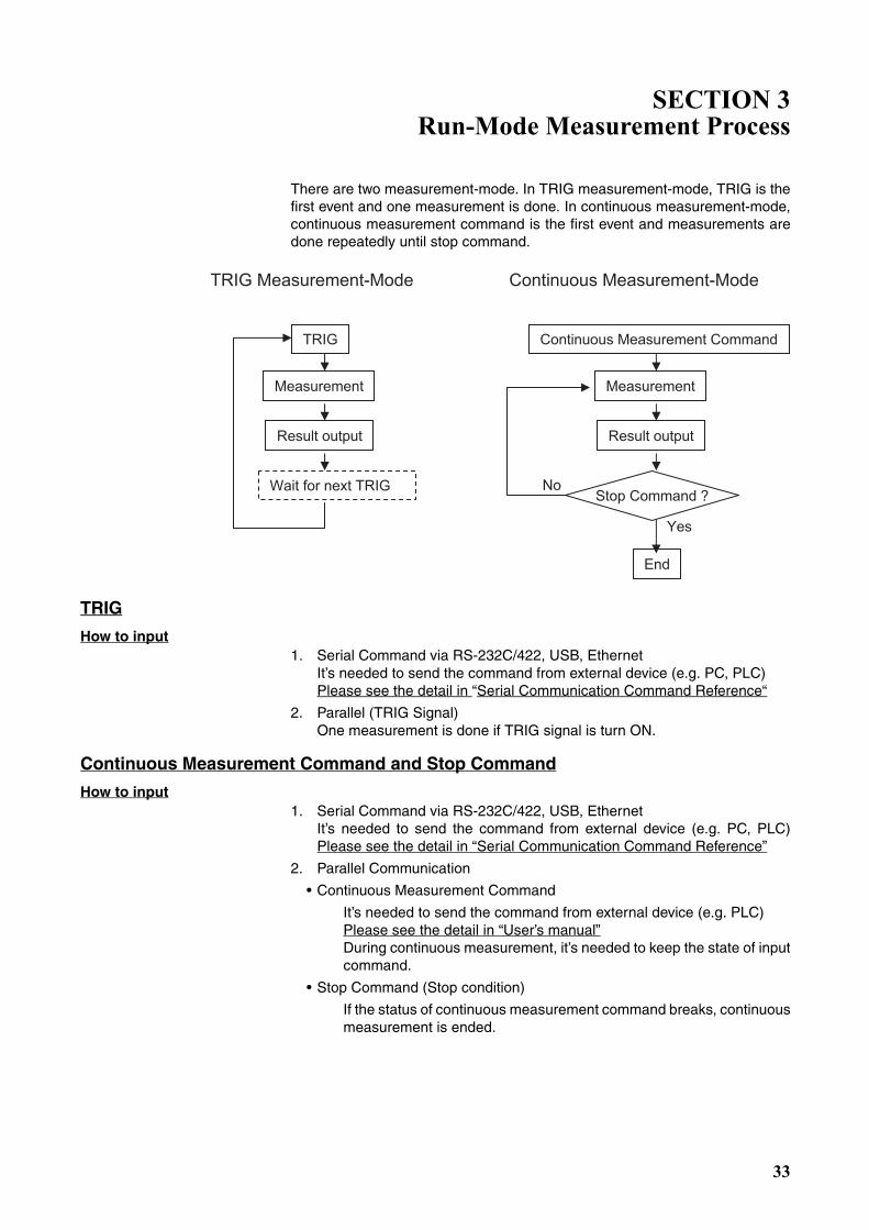
There are two measurement-mode. In TRIG measurement-mode, TRIG is thefirst event and one measurement is done. In continuous measurement-mode,continuous measurement command is the first event and measurements aredone repeatedly until stop command.
TRIG
How to input1. Serial Command via RS-232C/422, USB, Ethernet
It’s needed to send the command from external device (e.g. PC, PLC)Please see the detail in “Serial Communication Command Reference“
2. Parallel (TRIG Signal)One measurement is done if TRIG signal is turn ON.
Continuous Measurement Command and Stop Command
How to input1. Serial Command via RS-232C/422, USB, Ethernet
It’s needed to send the command from external device (e.g. PC, PLC)Please see the detail in “Serial Communication Command Reference”
2. Parallel Communication
• Continuous Measurement Command
It’s needed to send the command from external device (e.g. PLC)Please see the detail in “User’s manual”During continuous measurement, it’s needed to keep the state of inputcommand.
• Stop Command (Stop condition)
If the status of continuous measurement command breaks, continuousmeasurement is ended.
TRIG Measurement-Mode Continuous Measurement-Mode
TRIG
Measurement
Result output
Continuous Measurement Command
Measurement
Result output
Stop Command ?
End
Wait for next TRIG
Yes
No
33

Run-Mode Measurement Process
Z01E-EN-01+ZFX+SettingGuide.book Seite 34 Mittwoch, 13. Februar 2008 2:38 14
Measurement ResultsThere are three kind of results.
• Overall Judgement
• Individual Judgement (You can define up to 32 judgements)
• Individual data (You can define up to 32 data)
How to define “Individual Judgement”MENU mode -[Setup] -[Add func] -[Calculation] -[Judge]
Up to 32 (0 to 31) Individual Judgement can be defined. Each one is expres-sed by the following parameters/functions and each one has the upper/lowerthresholds. If result of expressionis in between both threshold, judgement isOK.
Parameters and functions
How to define “Individual Data”MENU mode -[Setup] -[Add func] -[Calculation] -[Data]
Up to 32 (0 to 31) Individual Data can be defined. Each one is expressed bythe parameters/functions which are same ones as individual judgement(please see the upper chart). Result value of expression can be output.
Parameter of each item Parameter of measurement item and position correction item.
Ex) Judgement of Pattern SearchEx) Gravity position of Area
List of function Please see the details in the Users-Manual. 16 functions are available.Ex) MAX: Max value of four argumentsEx) DIST: Distance between two points
(gravity and center ofmodel)Ex) OR: Logical sum of two arguments
List of operators +, -, x, /
Constant number Ex)
Individual Data You can use the Individual data which are already defined.
Individual Judgement You can use the Individual Judgement which are already defined.
Variables You can define the original “Variables”(up to 32). These variables can be expressed as same as “Individual judgement”.
34

Run-Mode Measurement Process
Z01E-EN-01+ZFX+SettingGuide.book Seite 35 Mittwoch, 13. Februar 2008 2:38 14
Overall Judgement
How to get Overall Judgement Output (OR Output)1. Parallel OR Signal
OR signal’s (ON/OFF) indicates the total judgement (OK or NG).
Setting about Overall Judgement
Setting Reflection of Individual Results MENU mode - [Setup] - [Add func] - [OR setting]
You can select which items results are reflected in the overall judgement that is output to the OR signal of the parallel interface.
Measurement Item ON (default) / OFF
Position correction
Calc./variable (Individual Data)
Calc./judge (Individual Judge)
Calc./alarm (Logging Monitor Alarm) ON / OFF (default)
Able / Disable MENU mode - [System] - [Output] - [Total jg. output] - [Parallel]If selecting OFF, OR signal is disable.
ON (default) / OFF
Output Polarity
(OR, DO[0:15])
MENU mode - [System] - [Comm] - [Parallel] - [Polarity]
ON condition of OR and Individual JudgementNG=ON: Signals turn ON when judgement is NG. (default )
OK=ON: Signals turn ON when judgement is OK.
OR output mode MENU mode - [System] - [Comm] - [OR output]
One-shot: OR signals turns ON for specified time only when ON condition is satisfied.
Level: ON/OFF status is held until it next changes after OR signalhas been output. (default)
OR Output time MENU mode - [System] - [Comm] - [OR output]Output time of OR signal as a one-shot signal
Range: 0 to 255 ms (default: 0 ms)
35

Run-Mode Measurement Process
Z01E-EN-01+ZFX+SettingGuide.book Seite 36 Mittwoch, 13. Februar 2008 2:38 14
Individual Judgement
How to get Individual Judgement Output1. Parallel ‘DO 0 to 31’Signals
DO[0:15] signals’ (ON/OFF) indicates the Individual judgements (OK or NG).
Setting about Individual Judgement
Able/Disable MENU mode - [System] - [Output] - [Judgement output] - [Parallel]
If selecting ON, judgements are output.
ON (default) / OFF
MENU mode - [System] - [Comm] - [Parallel]
Output Polarity(OR, DO[0:15])
ON condition of OR and Individual JudgementNG=ON: Signals turn ON when judgement is NG. (default )OK=ON: Signals turn ON when judgement is OK.
Output cycle Output cycle time. Set the time that is “Gate ON delay + Gate ON time”or more and that is shorter than the measurement cycle.
Range: 2.0 to 10000.0 ms (default: 10.0 ms)
Gate ON delay Delay time from output of measurement result to DO[0:15] until GATE signal turns on.
Range: 1.0 to 10000.0 ms (default: 1.0 ms)
Gate ON time Range: 1.0 to 10000.0 ms (default: 5.0 ms)
Handshaking Set the output method.OFF: Measurement results are output asynchronously
with external device. (default)ON: Measurement results are output synchronously with external device.
Timeout In case of “Handshaking = ON”, a timeout error occurs when there is no response from external device within timeout period.
Range: 1.0 to 60.0 s (default: 10 s)
DO15
Expression 15
DO14 DO13 DO12 DO11 DO10 DO9 DO8 DO7 DO6 DO5 DO4 DO3 DO2 DO1 DO0
DO15 DO14 DO13 DO12 DO11 DO10 DO9 DO8 DO7 DO6 DO5 DO4 DO3 DO2 DO1 DO0
Expression 0
Expression 31 Expression 16
Judgment result for expression 0 to 15
Judgment result for expression 16 to 31
1st time
2nd time
36
Run-Mode Measurement Process
Z01E-EN-01+ZFX+SettingGuide.book Seite 37 Mittwoch, 13. Februar 2008 2:38 14
Individual Data
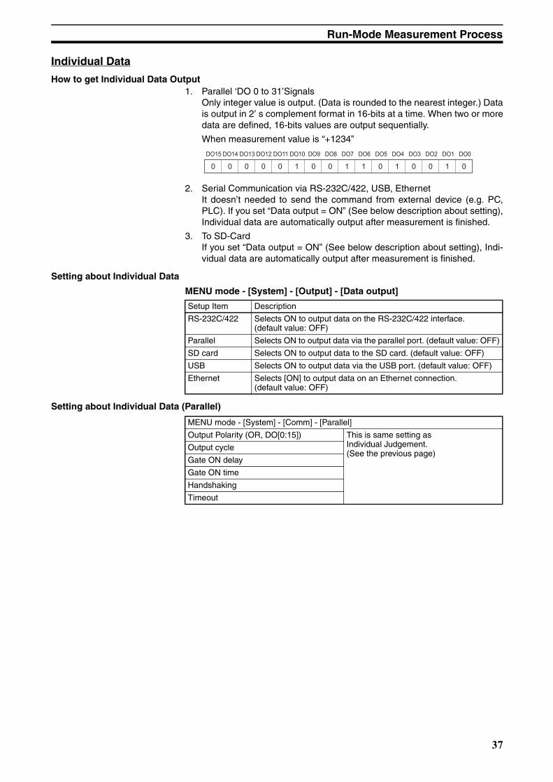
How to get Individual Data Output1. Parallel ‘DO 0 to 31’Signals
Only integer value is output. (Data is rounded to the nearest integer.) Datais output in 2’ s complement format in 16-bits at a time. When two or moredata are defined, 16-bits values are output sequentially.
When measurement value is “+1234”
2. Serial Communication via RS-232C/422, USB, EthernetIt doesn’t needed to send the command from external device (e.g. PC,PLC). If you set “Data output = ON” (See below description about setting),Individual data are automatically output after measurement is finished.
3. To SD-CardIf you set “Data output = ON” (See below description about setting), Indi-vidual data are automatically output after measurement is finished.
Setting about Individual Data
MENU mode - [System] - [Output] - [Data output]
Setting about Individual Data (Parallel)
DO15 DO14 DO13 DO12 DO11 DO10 DO9 DO8 DO7 DO6 DO5 DO4 DO3 DO2 DO1 DO0
0 0 0 0 1 1 0 0 0 1 00 1 0 0 1
Setup Item Description
RS-232C/422 Selects ON to output data on the RS-232C/422 interface. (default value: OFF)
Parallel Selects ON to output data via the parallel port. (default value: OFF)
SD card Selects ON to output data to the SD card. (default value: OFF)
USB Selects ON to output data via the USB port. (default value: OFF)
Ethernet Selects [ON] to output data on an Ethernet connection. (default value: OFF)
MENU mode - [System] - [Comm] - [Parallel]
Output Polarity (OR, DO[0:15]) This is same setting as Individual Judgement. (See the previous page)
Output cycle
Gate ON delay
Gate ON time
Handshaking
Timeout
37
Run-Mode Measurement Process
Z01E-EN-01+ZFX+SettingGuide.book Seite 38 Mittwoch, 13. Februar 2008 2:38 14
Setting about Individual Data (Serial/SD-Card) [ASCII Format]
MENU mode - [System] - [Output] - [Date format (Serial)/(SD Card)]
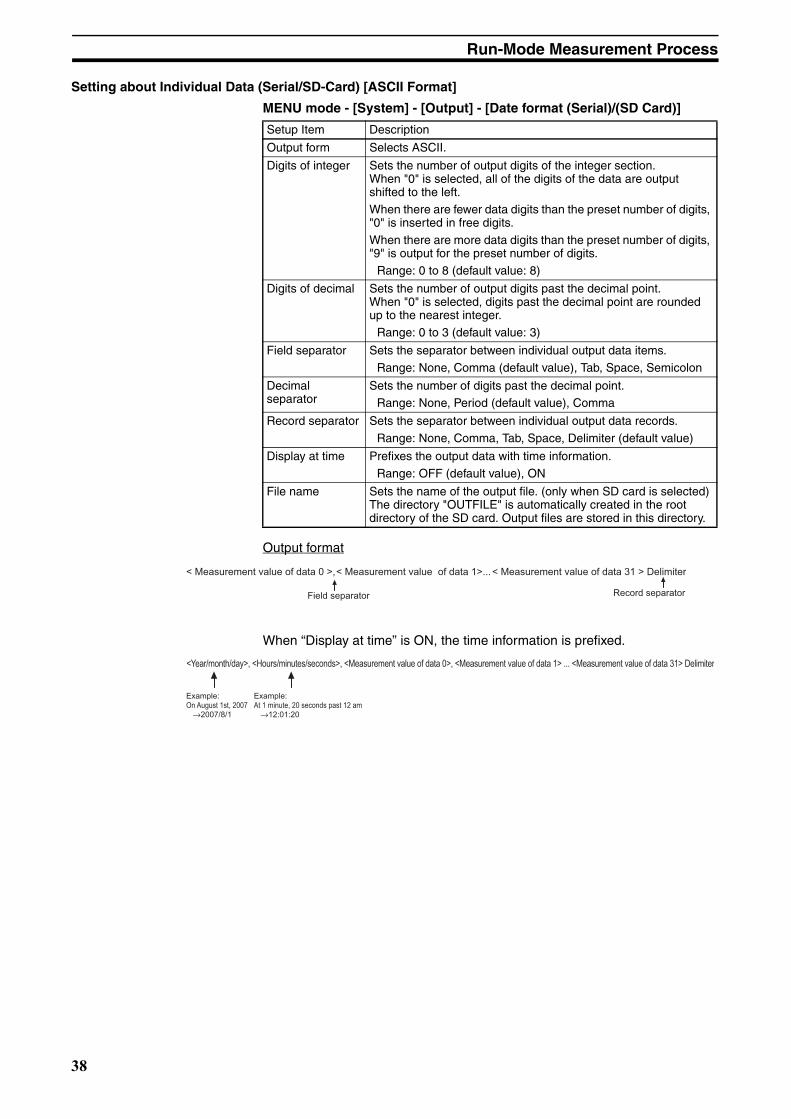
Output format
When “Display at time” is ON, the time information is prefixed.
Setup Item Description
Output form Selects ASCII.
Digits of integer Sets the number of output digits of the integer section. When "0" is selected, all of the digits of the data are output shifted to the left. When there are fewer data digits than the preset number of digits, "0" is inserted in free digits.
When there are more data digits than the preset number of digits, "9" is output for the preset number of digits.
Range: 0 to 8 (default value: 8)
Digits of decimal Sets the number of output digits past the decimal point. When "0" is selected, digits past the decimal point are rounded up to the nearest integer.
Range: 0 to 3 (default value: 3)
Field separator Sets the separator between individual output data items.
Range: None, Comma (default value), Tab, Space, Semicolon
Decimal separator
Sets the number of digits past the decimal point.Range: None, Period (default value), Comma
Record separator Sets the separator between individual output data records.
Range: None, Comma, Tab, Space, Delimiter (default value)
Display at time Prefixes the output data with time information.
Range: OFF (default value), ON
File name Sets the name of the output file. (only when SD card is selected) The directory "OUTFILE" is automatically created in the root directory of the SD card. Output files are stored in this directory.
< Measurement value of data 0 >,
Field separator Record separator
< Measurement value of data 1>...< Measurement value of data 31 > Delimiter
<Year/month/day>, <Hours/minutes/seconds>, <Measurement value of data 0>, <Measurement value of data 1> ... <Measurement value of data 31> Delimiter
Example: On August 1st, 2007 →2007/8/1
Example: At 1 minute, 20 seconds past 12 am →12:01:20
38

Run-Mode Measurement Process
Z01E-EN-01+ZFX+SettingGuide.book Seite 39 Mittwoch, 13. Februar 2008 2:38 14
Setting about Individual Data (Serial / SD-Card) [Binary Format]
MENU mode - [System] - [Output] - [Date format (Serial)/(SD Card)]
Output format
The value by 1000 times is output continuously as 4 bytes per single dataitem. Minus number are output as 2’ s complement.
When “Display at time” is ON, the time information is prefixed.
Setup Item Description
Output form Selects binary.
Display at time Prefixes the output data with time information.
Range: OFF (default value), ON
File name Sets the name of the output file. (only when SD card is selected)
4 bytes 4 bytes 4 bytes
Example: When data 0 is "256.324" and data 1 is "-1.000"
$00 $44$03 $FF$E9 $FF$FC $18
Data 0: 256324 Data 1: -1000(256.324 x 1000) (-1.000 x 1000)
<Measurement value of data 0 x 1000> <Measurement value of data 1 x 1000> ... <Measurement value of data 31 x 1000>
4 bytes 4 bytes 4 bytes
Example: When data 0 is "256.324" and data 1 is "-1.000"
$00 $44$03 $FF$E9 $FF$FC $18
Data 0: 256324 Data 1: -1000(256.324 x 1000) (-1.000 x 1000)
<Measurement value of data 0 x 1000> <Measurement value of data 1 x 1000> ... <Measurement value of data 31 x 1000>
39

Run-Mode Measurement Process
Z01E-EN-01+ZFX+SettingGuide.book Seite 40 Mittwoch, 13. Februar 2008 2:38 14
Parallel Interface Timing Chart
Ex.) TRIG Measurement, Handshaking: OFF
Explanation of operation
1. When the measurement trigger (TRIG signal) is input from the external device, measurement is executedonce synchronized with the rising edge of the TRIG signal (OFF -> ON).
2. The GATE signal is used to control the timing at which the external device captures measurement results.Set the Gate ON delay (T3) and Gate ON time (T4) so that T3+T4<T5.
3. When parallel output is set to "ON" as the data output destination, data is output for the number of times inthe expression set at "Calculation (data)" (maximum 32 times). When parallel output is OFF, data is not out-put.
4. When parallel output is set to "ON" as the judgment output destination, judgment is output for the numberof times in the expression set at "Calculation (judgment)" (maximum twice). When parallel output is OFF,judgment is not output.
5. The overall judgment is output. Overall judgment is NG if there is even one NG for the preset measurementitems and judgment results in the expression. In the case of level output, the ON/OFF status of the OR signaldoes not change until the next output as shown in this example.
6. When the timing for turning the ENABLE signal ON is set to "end of image input", a delay occurs until outputis started after the ENABLE signal turns ON as measurement is also executed after the ENABLE signalturns ON. Do not input the next trigger until measurement is completed.
T1:Trigger input time
Set to ON for at least 0.5 ms.
T2:Measurement time
This time is "image input" + "measurement". This time can be changed to only "image input" or "image input" + "measurement" + "display".
T3:Gate ON delay
This is the time to wait until stable output data can be obtained. This time can be changed.
T4:Gate ON time
This is the time required for the external device to capture output data from the Controller. This time can be changed.
T5:Output cycle
This is the interval in which the DO signal state changes. This time can be changed.
T6:Total output time
This time is equivalent to "output cycle (T5) x number of output data items". Input the trigger at an interval longer than this time. When the total output time is longer than T2, non-output data accumu-lates in the Controller as the next measurement is executed before measurement results are output. When the Controller becomes filled up with this non-output data, data can no longer accumulate in the Controller. When this happens, output of non-output data continues, and the next measurement is no longer possible until queued data has finished accumulating.
ENABLE
TRIG
RUN
OR
DO
GATE
(1)
T2 T2
T3
(3)
T4
T5
T6
Overall judgment
Data 0 Data 1 Data 31 Data 0Judgment0 to 15
Judgment16 to 31
OFF
ON
OFF
ON
OFF
ON
OFF
ON
OFF
ON
OFF
ON
(4)
(5)
T1 T1
(2)
(6)
40
Z01E-EN-01+ZFX+SettingGuide.book Seite 41 Mittwoch, 13. Februar 2008 2:38 14
SECTION 4Item Overview
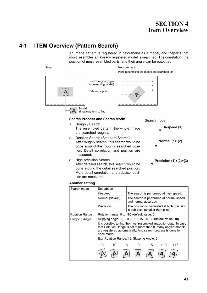
4-1 ITEM Overview (Pattern Search)An image pattern is registered in beforehand as a model, and theparts thatmost resembles an already registered model is searched. The correlation, theposition of most resembled parts, and their angle can be outputted.
Search Process and Search Mode
1. Roughly SearchThe resembled parts in the whole imageare searched roughly.
2. Detailed Search (Standard Search)After roughly search, this search would bedone around the roughly searched posi-tion. Detail correlation and position aremeasured.
3. High-precision SearchAfter detailed search, this search would bedone around the detail searched position.More detail correlation and subpixel posi-tion are measured.
Another setting
Setup MeasurementParts resembling the model are searched for.
Search region (region for searching model)
Reference point
Model (image pattern to find)
Search mode See above
Hi-speed The search is performed at high speed.
Normal (default) The search is performed at normal speed and normal accuracy.
Precision The position is calculated at high precision in sub-pixel (smaller than pixel).
Rotation Range Rotation range: 0 to 180 (default value: 0)Skipping angle: 1, 2, 3, 5, 10, 15, 20, 30 (default value: 10)
It is possible to find the most resembled image to rotate. In case that Rotation Range is set to more than 0, many angled models are registered automatically. And search process is done for each model.
E.g. Rotation Range: 15, Skipping Angle: 5
Skipping Angle
Hi-speed (1)
Normal (1)+(2)
Precision (1)+(2)+(3)
Search mode
-15 -10 -5 0 +5 +10 +15
AA A AA AA
41
4-1 ITEM Overview (Pattern Search) Item Overview
Z01E-EN-01+ZFX+SettingGuide.book Seite 42 Mittwoch, 13. Februar 2008 2:38 14
Interpolation ON/OFF (default)
The angle is calculated as a numerical value down to three digits past the decimal point based on the value obtained in skipping angle units. Note, however, that the processing time increases. This function is enabled only when the search mode is the nor-mal mode or the precision mode.
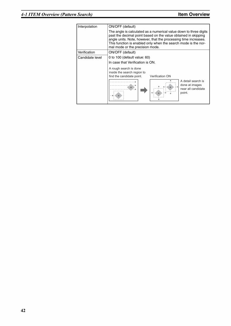
Verification ON/OFF (default)
0 to 100 (default value: 60)
In case that Verification is ON.Candidate level
+
+
+
+
A rough search is done
inside the search region to
find the candidate point. Verification ON
A detail search is
done at images
near all candidate
point.
42
4-2 ITEM Overview (Sensitive Search) Item Overview
Z01E-EN-01+ZFX+SettingGuide.book Seite 43 Mittwoch, 13. Februar 2008 2:38 14
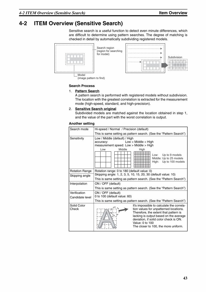
4-2 ITEM Overview (Sensitive Search)Sensitive search is a useful function to detect even minute differences, whichare difficult to determine using pattern searches. The degree of matching ischecked in detail by automatically subdividing registered models.
Search Process
1. Pattern SearchA pattern search is performed with registered models without subdivision.The location with the greatest correlation is extracted for the measurementmode (high-speed, standard, and high-precision).
2. Sensitive Search originalSubdivided models are matched against the location obtained in step 1,and the value of the part with the worst correlation is output.
Another setting
Model(image pattern to find)
Search region(region for searchingfor model)
Subdivision
Search mode Hi-speed / Normal / Precision (default)
This is same setting as pattern search. (See the “Pattern Search”)
Sensitivity Low / Middle (default) / Highaccuracy: Low < Middle < Highmeasurement speed: Low > Middle > High
Rotation Range Rotation range: 0 to 180 (default value: 0)Skipping angle: 1, 2, 3, 5, 10, 15, 20, 30 (default value: 10)
This is same setting as pattern search. (See the “Pattern Search”)Skipping angle
Interpolation ON / OFF (default)This is same setting as pattern search. (See the “Pattern Search”)
Verification
Candidate level
ON / OFF (default)0 to 100 (default value: 60)
This is same setting as pattern search. (See the “Pattern Search”)
Solid Color Check
It’s impossible to calculate the correla-tion values for unpatterned locations. Therefore, the extent that pattern is lacking is output based on the average deviation, if solid color check is ON. Value: 0 to 100 The closer to 100, the more uniform.
Low Middle High
Low: Up to 9 modelsMiddle: Up to 25 modelsHigh: Up to 100 models
43
4-3 ITEM Overview (Flexible Search) Item Overview
Z01E-EN-01+ZFX+SettingGuide.book Seite 44 Mittwoch, 13. Februar 2008 2:38 14
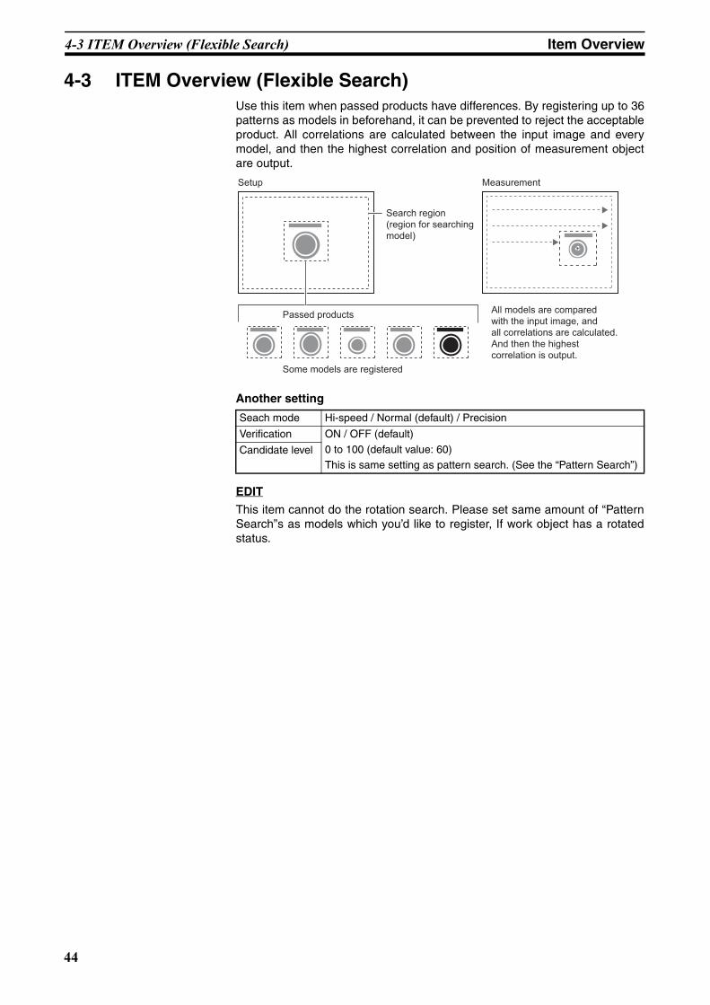
4-3 ITEM Overview (Flexible Search)Use this item when passed products have differences. By registering up to 36patterns as models in beforehand, it can be prevented to reject the acceptableproduct. All correlations are calculated between the input image and everymodel, and then the highest correlation and position of measurement objectare output.
Another setting
EDIT
This item cannot do the rotation search. Please set same amount of “PatternSearch”s as models which you’d like to register, If work object has a rotatedstatus.
Seach mode Hi-speed / Normal (default) / Precision
Verification ON / OFF (default)
0 to 100 (default value: 60)This is same setting as pattern search. (See the “Pattern Search”)
Candidate level
Setup Measurement
Search region(region for searchingmodel)
Passed products
Some models are registered
All models are compared with the input image, and all correlations are calculated. And then the highest correlation is output.
44

4-4 ITEM Overview (Graphic Search) Item Overview
Z01E-EN-01+ZFX+SettingGuide.book Seite 45 Mittwoch, 13. Februar 2008 2:38 14
4-4 ITEM Overview (Graphic Search)Use this item when it’s difficult to search for a model from partially clippedimages or low contrast images. In a pattern search, measurement is based onthe contrast information. However, measurement is based on profile informa-tion in this item.
Model registration procedure if the shape of object is like a box, Ellipse or line.
1. Select [Box], [Ellipse] or [Line].
2. Trace the profile of object. And select [Apply].-->The profile is traced.
Model registration procedure if the shape of object is not simple.
1. Select [Auto] and enclose the area in which the profile is to betraced.
2. Select [Auto] displayed on the lower left on the screen.-->The profile is traced.
3. If the profile is partially clipped, trace by [Free], [Box], [Ellipse] or [Line].
4. Delete any noise with the [Erase] tool if noise has been traced.
Another setting
Setup MeasurementParts resembling the model are searched for stably evenin the following environment.
Lots of noise Partially clipped
Low contrast Inclined
Search region(region for searchingfor model)
Reference point
Model (image pattern to find)
Search mode Hi-speed / Normal (default) / PrecisionThis is same setting as pattern search. (See the “Pattern Search”)
Rotation Range Rotation range: 0 to 180 (default value: 0)
Skipping angle: 1, 2, 3, 5, 10, 15, 20, 30 (default value: 10)
This is same setting as pattern search. (See the “Pattern Search”)Skipping angle
Interpolation ON / OFF (default)This is same setting as pattern search. (See the “Pattern Search”)
Candidate level 0 to 100 (default value: 60)
This is same setting as pattern search. (See the “Pattern Search”)
45

4-5 ITEM overview (Area) Item Overview
Z01E-EN-01+ZFX+SettingGuide.book Seite 46 Mittwoch, 13. Februar 2008 2:38 14
4-5 ITEM overview (Area)The area, gravity and angle of the desired color can be measured. Therefore,the size, the position and the inclination of the measurement target can beinspected.When color camera is connected to the controller, up to four colors can bespecified as the measurement colors.When monochrome camera is connected, black-and-white image is binarized.White pixels are targeted in measurement.
Another setting
Notice:
The color pickup isn’t done by clicking [AUTO] in themeasurement Item. Please select the pick up color inthe color pickup screen.
Measure axis angle
ON / OFF (default)Set whether or not to measure the angle. (When selecting [ON], the processing time increases.)
Fill profile ON / OFF (default)
This is efficient, when passed products doesn’t have the uniformity inside but has a same outer shape.
When measuring the outer shape of the measurement target, set this to [ON]. If this is set to [ON], all of the area between the start point and the end point inside the measurement region are mea-sured as the measurement target color.
Start point: untargeted color --> trageted colorEnd point: targeted color --> untargeted colors
Setup Measurement
Measurement
region
The colors of the measurement
target are picked up.
Angle
Gravity
Area
θ
The area, gravity and angle
of the desired colors can be
measured, based on the total
pixels of desired colors.
Passed products
Input image (Fill profile: OFF) Fill profile: ON
End point
Start point
Pixels that are measurement target color are not recognized as the start point as pixels that are colors outside of measurement target are next scanned.
AUTO
Register model
Reference model
Search region TEA
RegionImg Adj Detail Limits
Reference point
46

4-6 ITEM Overview (Labeling) Item Overview
Z01E-EN-01+ZFX+SettingGuide.book Seite 47 Mittwoch, 13. Februar 2008 2:38 14
4-6 ITEM Overview (Labeling)A group of colors which is measured is counted as a “label”. Label Nos. canbe assigned to every label after being arranged in order of size and position.The total number of labels and the size/position of any label can be output.
When color camera is connected to the controller, up to four colors can bespecified as the measurement colors.
When monochrome camera is connected, black-and-white image is binarized.White pixels are targeted in measurement.
Another setting
Setup Measurement
Measurementregion
The colors of the measurement target are picked up.
When label Nos. are arranged in order of the largest area (from large to small)
Label 0
Label 1
Label 2
Labeling mode Normal (default) / Precision
When “Normal” is selected, the image is measured at high speed after compressed to 1/2 size in both the horizontal and vertical axes.
Sort mode Area descending order From large area to small area
Area ascending order From small area to large area
X gravity descending order From large X position to small X position
X gravity ascending order From small X position to large X position
Y gravity descending order From large Y position to small Y position
Y gravity ascending order From small Y position to large Y position
Label No. 0 to 2499 (default value : 0)
Sets the label No. whose data (area/position) is to be output.
Measure axis angle ON / OFF (default)Set whether or not to measure the angle. (When selecting [ON], the processing time increases.)
Measure perimeter ON / OFF (default)
Set whether or not to measure the following parameters. (When selecting [ON], the processing time increases.)- Perimeter
- Length X
- Length Y
Measure roundness ON / OFF (default)
Set whether or not to measure the roundness. (When selecting [ON], the processing time increases.)
Roundness = 4π x area) / (perimeter x perimeter)
Filling up holes ON / OFF (default)
Select how to process the parts of untargeted color which are enclosed by the target color, such as a doughnut. When [ON] is set, that parts are recognized as the target color. (When selecting [ON], the processing time increases.)
Length Y
Length X
Input image Filling up holes: ON
Measurement target
47
4-6 ITEM Overview (Labeling) Item Overview
Z01E-EN-01+ZFX+SettingGuide.book Seite 48 Mittwoch, 13. Februar 2008 2:38 14
Notice:
The color pickup isn’t done by clicking [AUTO] in themeasurement Item. Please select the pick up color inthe color pickup screen.
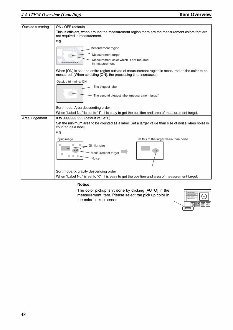
Outside trimming ON / OFF (default)
This is efficient, when around the measurement region there are the measurement colors that are not required in measurement.
e.g.
When [ON] is set, the entire region outside of measurement region is measured as the color to be measured. (When selecting [ON], the processing time increases.)
Sort mode: Area descending order
When “Label No.” is set to “1”, it is easy to get the position and area of measurement target.
Area judgement 0 to 9999999.999 (default value: 0)
Set the minimum area to be counted as a label. Set a larger value than size of noise when noise is counted as a label.
e.g.
Sort mode: X gravity descending orderWhen “Label No.” is set to “0”, it is easy to get the position and area of measurement target.
Measurement target
Measurement color which is not requiredin measurement
Measurement region
Outside trimming: ON
The second biggest label (measurement target)
The biggest label
Input image Set this to the larger value than noise
Similar size
Measurement target
Noise
AUTO
Register model
Reference model
Search region TEA
RegionImg Adj Detail Limits
Reference point
48

4-7 ITEM Overview (Position) Item Overview
Z01E-EN-01+ZFX+SettingGuide.book Seite 49 Mittwoch, 13. Februar 2008 2:38 14
4-7 ITEM Overview (Position)This item detects the edge, based on the change of brightness. Use this itemto measure the coordinates of the edge of a measurement target.
Edge search direction
The edge is searched from the start point towards the end point of the mea-surement region.
Another setting
Measurement mode Average (default) / Peak / bottomSet the definition of the edge position.
Color mode Select the method of image adjustment.
Filter mode Color filter is used for image adjustment.
Pickup mode Color pickup is used for image adjustment.
Split size size1 to 99 (default value: 1)
Set the calculation width when measuring the peak/bottom/average position. (The measurement region is divided into smaller areas to measure the peak/bottom/average position)
Color Light-->Dark (default) / Dark-->LightSelect the direction of the destiny change.
Setup
Measurement regionChange of brightness: light --> dark
The edge is searched in the measurement region according the preset direction and change of brightness
Measurement
Start point End point End point
Start point
Start point
End point
End point Start point
Bottom (side near start point)
Peak (side far from start point)
Average
Split size
End point Start point
49

4-7 ITEM Overview (Position) Item Overview
Z01E-EN-01+ZFX+SettingGuide.book Seite 50 Mittwoch, 13. Februar 2008 2:38 14
Edge level 0 to 100 (%) (default value: 50)
Set the level of density change to be judges as an edge.Edge is detected as follows:1. The density distribution of the whole measurement region is calculated.2. The maximum value is set to 100%. Minimum value is set to 0%.3. Place where the destiny is equal to edge level is detected as an edge.
Noise level 0 to 255 (default value: 20)
Set the level to be judged as noise.
Normally this value may be default value of 20. However, set a higher value when noise is detected as an edge.e.g.(Max density -min density) < noise level --> Judged as “no edge”(Max density -min density) > noise level --> Judged as “edge”
Noise width 0 to 255 (default value: 0)Set the level to be judged as noise.
Normally this value may be default value of 0. However, set a higher value when noise is detected as an edge.
Measurement region
Maximum density value
Edge level
Minimum density value
100%
50%
0%
Measurement region Measurement region
Maximum density value 60 Maximum density value 25
Minimum density value 10
Minimum density value 15
60-15>30Measurement is performed with an edge judged as being present.
25-10<30Process as "no edge". (Measurement result is NG.)
Edge detection point
Measurement region
Noise width (pixel)
Edge level50%
Noise is judged as being present when the densitiy distribution is at the edge level or lower in the preset range.
50

4-8 ITEM Overview (Width) Item Overview
Z01E-EN-01+ZFX+SettingGuide.book Seite 51 Mittwoch, 13. Februar 2008 2:38 14
4-8 ITEM Overview (Width)This item detects two edges, based on the change of brightness. Use thisitem to measure the distance between two edges of a measurement target.
Another setting
Startpoint
Endpoint
Measurement region
Setup Measurement
Edge 1(start point side)
Edge 2(end point side)
Dimension
Edge 1 is searched from start point towards the end point.Edge 2 is searched from end point towards the start point.
Measurement mode Average (default) / Maximum / minimumSet the definition of the distance.
Color mode Filter mode (default) / Pickup modeThis is same setting as position. (See the “Position”)
Split size 1 to 99 (default value: 1)This is same setting as position. (See the “Position”)
Color 1, 2 Light --> Dark (default) / Dark --> LightThis is same setting as position. (See the “Position”)
Edge level 1, 2 0 to 100 (%) (default value: 50)This is same setting as position. (See the “Position”)
Noise level 1, 2 0 to 255 (default value: 20)This is same setting as position. (See the “Position”)
Noise width 1, 2 0 to 255 (default value: 0)This is same setting as position. (See the “Position”)
Width when [Maximum] is selected
Width when [Minimum] is selected
Start point End point
Split size
51
4-9 ITEM Overview (Count) Item Overview
Z01E-EN-01+ZFX+SettingGuide.book Seite 52 Mittwoch, 13. Februar 2008 2:38 14
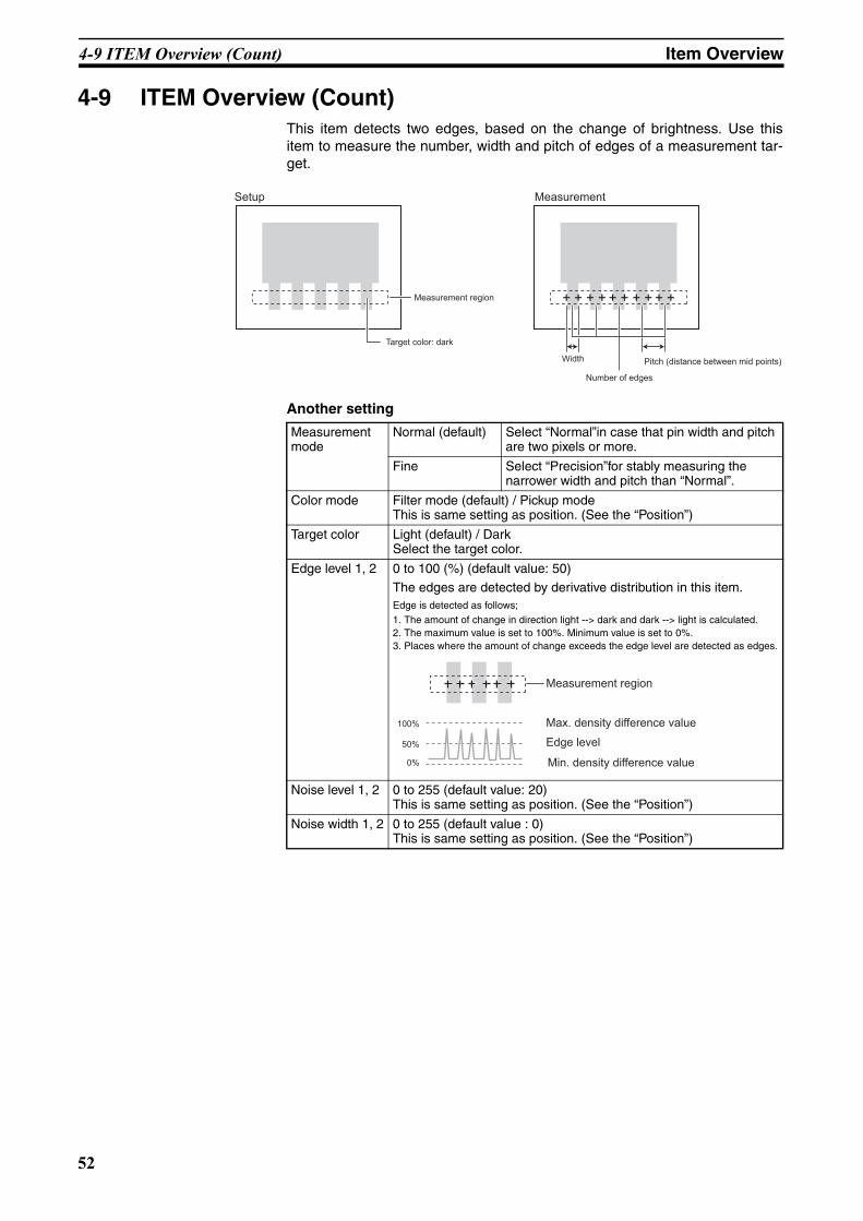
4-9 ITEM Overview (Count)This item detects two edges, based on the change of brightness. Use thisitem to measure the number, width and pitch of edges of a measurement tar-get.
Another setting
Setup Measurement
Measurement region
Target color: dark
Width Pitch (distance between mid points)
Number of edges
Measurement mode
Normal (default) Select “Normal”in case that pin width and pitch are two pixels or more.
Fine Select “Precision”for stably measuring the narrower width and pitch than “Normal”.
Color mode Filter mode (default) / Pickup modeThis is same setting as position. (See the “Position”)
Target color Light (default) / Dark Select the target color.
Edge level 1, 2 0 to 100 (%) (default value: 50)
The edges are detected by derivative distribution in this item.Edge is detected as follows;1. The amount of change in direction light --> dark and dark --> light is calculated. 2. The maximum value is set to 100%. Minimum value is set to 0%.3. Places where the amount of change exceeds the edge level are detected as edges.
Noise level 1, 2 0 to 255 (default value: 20)This is same setting as position. (See the “Position”)
Noise width 1, 2 0 to 255 (default value : 0)This is same setting as position. (See the “Position”)
Measurement region
Max. density difference value
Edge level
Min. density difference value
100%
50%
0%
52

4-10 ITEM Overview (Angle) Item Overview
Z01E-EN-01+ZFX+SettingGuide.book Seite 53 Mittwoch, 13. Februar 2008 2:38 14
4-10 ITEM Overview (Angle)This item uses two “Position”items. Specifically this Item finds the two edgesin two measurement regions and outputs the angle between two edge points.
Angle
Angle is calculated according to thepositional relationship between the 2edge positions.
Another setting
Setup Measurement
Measurement regionChange of brightness: light --> dark
The edges are searched in the two measurement regions according the preset direction and change of brightness. Theinclination of the straight line made by two points is calculated.
Color mode Filter mode (default) / Pickup modeThis is same setting as position. (See the “Position”)
Measurement mode 1, 2 Average (default) / Peak / bottomThis is same setting as position. (See the “Position”)
Split size 1, 2 1 to 99 (default value : 1)This is same setting as position. (See the “Position”)
Color 1, 2 Light --> Dark (default) / Dark --> LightThis is same setting as position. (See the “Position”)
Edge level 1, 2 0 to 100 (%) (default value: 50)This is same setting as position. (See the “Position”)
Noise level 1, 2 0 to 255 (default value: 20)This is same setting as position. (See the “Position”)
Noise width 1, 2 0 to 255 (default value: 0)This is same setting as position. (See the “Position”)
: Edge position 1 : Edge position 2
-180 to 0°
0 to 180°
53

4-11 ITEM Overview (Bright) Item Overview
Z01E-EN-01+ZFX+SettingGuide.book Seite 54 Mittwoch, 13. Februar 2008 2:38 14
4-11 ITEM Overview (Bright)Use this item to measure the brightness of measurement targets. The densityaverage and density deviation (brightness fluctuations) are output.
Setup Measurement
Measurement region Density average,density deviation
2550
Brightness: black Brightness: white
1270
Deviation: small Deviation: big
e.g.1
Deviation of both objects are 0.The difference can be detected by brightness
e.g.2
Brightness of both objects are 127.5.The difference can be detected by Deviation.
White & Black Just middle betweenwhite and black
54
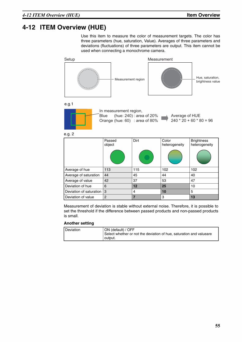
4-12 ITEM Overview (HUE) Item Overview
Z01E-EN-01+ZFX+SettingGuide.book Seite 55 Mittwoch, 13. Februar 2008 2:38 14
4-12 ITEM Overview (HUE)Use this item to measure the color of measurement targets. The color hasthree parameters (hue, saturation, Value). Averages of three parameters anddeviations (fluctuations) of three parameters are output. This item cannot beused when connecting a monochrome camera.
Measurement regionHue, saturation,brightness value
Setup Measurement
In measurement region,Blue (hue: 240) : area of 20%Orange (hue: 60) : area of 80%
Average of HUE240 * 20 + 60 * 80 = 96
e.g. 2
Measurement of deviation is stable without external noise. Therefore, it is possible toset the threshold if the difference between passed products and non-passed productsis small.
Another setting
Passed object
Dirt Color heterogeneity
Brightness heterogeneity
Average of hue 113 115 102 102
Average of saturation 44 45 44 40
Average of value 42 37 53 47
Deviation of hue 6 12 25 10
Deviation of saturation 3 4 10 5
Deviation of value 2 7 3 13
Deviation ON (default) / OFFSelect whether or not the deviation of hue, saturation and valueare output.
e.g.1
55

4-13 ITEM Overview (Defect) Item Overview
Z01E-EN-01+ZFX+SettingGuide.book Seite 56 Mittwoch, 13. Februar 2008 2:38 14
4-13 ITEM Overview (Defect)Use this item to detect dirt, scratching, chipping, burrs and other defects onthe plain measurement target. The defect value and position of the defectwhich has highest defect value are output. And the number of defects are alsooutput.
Number of defects
The extent of the defects is calculated in subdividedregions, and regions at or exceeding the defectthreshold are output as the number of defects.
Even if you see only one defect on the screen, thenumber of defects is often more than one.
Measurement region
Measurement region
Setup Measurement
Scratch
Subdivision
The measurement region is automatically subdivided intosmall sections to detect for changes in their respectivebrightness (density).
Measurement region
Line Circum/Arc AreaMeasurement
regionMeasurement region
This is mainly for detecting the chipping and burrs. One straight line can be drawn.
This is mainly for detecting thechipping and burrs on round shapeobject. One circumference or arc can be drawn.
This is mainly for detecting the scratches and dirt. A combination of up to five shapes (rectangles, ellipse, circles, polygons) can be drawn.
56
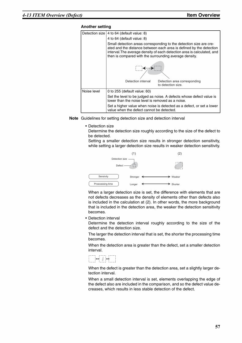
4-13 ITEM Overview (Defect) Item Overview
Z01E-EN-01+ZFX+SettingGuide.book Seite 57 Mittwoch, 13. Februar 2008 2:38 14
Another setting
Note Guidelines for setting detection size and detection interval
• Detection sizeDetermine the detection size roughly according to the size of the defect tobe detected. Setting a smaller detection size results in stronger detection sensitivity,while setting a larger detection size results in weaker detection sensitivity.
When a larger detection size is set, the difference with elements that arenot defects decreases as the density of elements other than defects alsois included in the calculation at (2). In other words, the more backgroundthat is included in the detection area, the weaker the detection sensitivitybecomes.
• Detection intervalDetermine the detection interval roughly according to the size of thedefect and the detection size.
The larger the detection interval that is set, the shorter the processing timebecomes.
When the detection area is greater than the defect, set a smaller detectioninterval.
When the defect is greater than the detection area, set a slightly larger de-tection interval.
When a small detection interval is set, elements overlapping the edge ofthe defect also are included in the comparison, and so the defect value de-creases, which results in less stable detection of the defect.
Detection size 4 to 64 (default value: 8)4 to 64 (default value: 8)
Small detection areas corresponding to the detection size are cre-ated and the distance between each area is defined by the detection interval.The average density of each detection area is calculated, and then is compared with the surrounding average density.
Noise level 0 to 255 (default value: 60)
Set the level to be judged as noise. A defects whose defect value is lower than the noise level is removed as a noise.
Set a higher value when noise is detected as a defect, or set a lower value when the defect cannot be detected.
Detection interval Detection area correspondingto detection size.
(1) (2)
Detection size
Defect
Sensivity
Proecessing time
Stronger
Longer
Weaker
Shorter
57
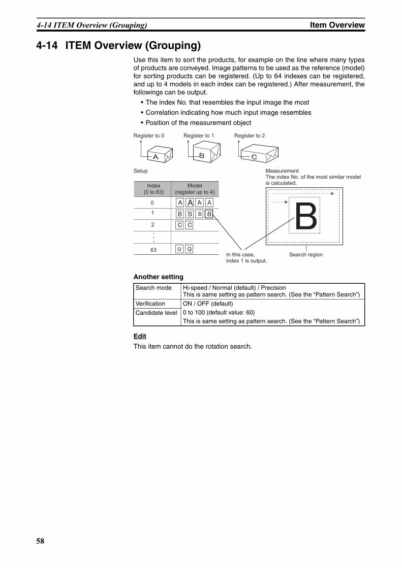
4-14 ITEM Overview (Grouping) Item Overview
Z01E-EN-01+ZFX+SettingGuide.book Seite 58 Mittwoch, 13. Februar 2008 2:38 14
4-14 ITEM Overview (Grouping)Use this item to sort the products, for example on the line where many typesof products are conveyed. Image patterns to be used as the reference (model)for sorting products can be registered. (Up to 64 indexes can be registered,and up to 4 models in each index can be registered.) After measurement, thefollowings can be output.
• The index No. that resembles the input image the most
• Correlation indicating how much input image resembles
• Position of the measurement object
Another setting
Edit
This item cannot do the rotation search.
Search mode Hi-speed / Normal (default) / PrecisionThis is same setting as pattern search. (See the “Pattern Search”)
Verification ON / OFF (default)
0 to 100 (default value: 60)This is same setting as pattern search. (See the “Pattern Search”)
Candidate level
Register to 0 Register to 1 Register to 2
Model(register up to 4)
0
Index(0 to 63)
63
1
2
MeasurementThe index No. of the most similar model is calculated.
Setup
Search regionIn this case,index 1 is output.
58

Z01E-EN-01+ZFX+SettingGuide.book Seite 59 Mittwoch, 13. Februar 2008 2:38 14
SECTION 5Appendices
5-1 What is decided by AUTO settingAUTO setting in measurement Items
After drawing the region (*1), click the [AUTO].The following settings are done.(*1)Model region: (Pattern Search / Sensitive Search /Graphic Search / Flexible Search / Grouping)Measurement region: (Area / Labeling / Position /Width / Count / Angle / Bright / Hue / Defect)
(*2)Model region: (Pattern Search / Sensitive Search / Graphic Search / FlexibleSearch / Grouping)Measurement region: (Area / Labeling / Position / Width / Count/ Angle /Bright / Hue / Defect)
Setting Available Item Description
Color filter Pattern SearchSensitive SearchGraphic SearchFlexible SearchPosition WidthCount AngleBrightDefectGrouping
The image (*2) is analyzed. And then, the best filter is selected.
Model Image Pattern SearchSensitive SearchFlexible Search
After the color filter is automatically selected, the image is registered as the model. If the model region is changed after AUTO setting, the model is updated but the color filter isn’t updated.
Threshold AreaLabelingPositionWidthCountAngleBrightHUE
The threshold values are automatically set.
Edge search color PositionWidthCountAngle
The edge search color (direction of the destiny change) in detail setting is auto-matically set.
Reference value All items The measurement value of the current displayed image is registered as the refrence value.If the region (*2) is changed, the refer-ence value is updated.
AUTO
Register model
Reference model
Search region TEA
RegionImg Adj Detail Limits
Reference point
59

5-2 BANK and BANK-Group Appendices
Z01E-EN-01+ZFX+SettingGuide.book Seite 60 Mittwoch, 13. Februar 2008 2:38 14
5-2 BANK and BANK-GroupThe basic knowledge of BANK and BANK-Group
What is BANK?
BANK has the following setting data.
• Camera [Shutter Speed / Light Control (In case of using intelligent camera / Calibration / etc]
• Measurement Item [C1*: up to 32 items, C2*: up to 128 items]
• Position Correction
• Additional Function [Calculation / Logging Monitor (only ZFX-C2*) / OR setting ]
What is BANK-Group?
BANK-Group can have up to 32 BANKs.
• ZFX-C controller can have one BANK-Group, if not using SD-card.
• ZFX-C controller can have up to 32 BANK-Groups, if using SD-card.
SetupTool SystemBank Save
Top menu
TEA
LIVE
ItemRegister Position Add funcCameras
BANK data
Bank group 0
Bank 0Bank 1
Bank 30Bank 31
Bank group 01
2
Bank group 31
Max. 1024 banks
Bank group 0: Data is saved on internal flash memory.Bank groups 1 to 31: Data is saved on SD card.
SD card(capacity: 256 MB)
Bank 0Bank 1
Bank 30Bank 31
Bank 0Bank 1
Bank 30Bank 31
Bank 0Bank 1
Bank 30Bank 31
Bank 0Bank 1
Bank 30Bank 31
60

5-2 BANK and BANK-Group Appendices
Z01E-EN-01+ZFX+SettingGuide.book Seite 61 Mittwoch, 13. Februar 2008 2:38 14
Which BANK/BANK-Group should be set, just after start-up?They can be set in the following menu.
MENU mode - [System] - [Startup]
How to switch BANK/BANK-Group1. Manu Operation
BANK Menu-mode - [Bank] - [Bank] - [Switch]BANK-Group Menu-mode - [Bank] - [Bank Group] - [Switch]
2. Serial Command via RS-232C/422, USB, Ethernet (*1)
3. Parallel Command
It’s needed to send the command from external device (e.g. PLC)Please see the detail in “User’s manual”
How to upload BANK/BANK-Group1. Upload BANK 0-31 (BANK-Group 0-31) to ZFX from SD card
a) Manu OperationBANK Menu-mode - [Tool] - [Backup] - [Bank data] - [Load]BANK-Group Menu-mode - [Tool] - [Backup] - [Bank Group data] - [Load]
b) Serial Command via RS-232C/422, USB, Ethernet (*1)
2. Upload BANK 0-31 (BANK-Group 0-31) to ZFX from External device (e.g. PC, PLC)
a) Serial Command via RS-232C/422, USB, Ethernet (*1)
How to back up BANK/BANK-Group1. Back up BANK 0-31 (BANK-Group 0-31) to SD card from ZFX
a) Manu OperationBANK Menu-mode - [Tool] - [Backup] - [Bank data] - [Save]BANK-Group Menu-mode - [Tool] - [Backup] - [Bank Group data] - [Save]
b) Serial Command via RS-232C/422, USB, Ethernet (*1)
2. Back up BANK 0-31 (BANK-Group 0-31) to External device (e.g. PC, PLC) from ZFX
a) Serial Command via RS-232C/422, USB, Ethernet (*1)
Note (*1) It’s needed to send the command from external device (e.g. PC, PLC)Please see the detail in “Serial Communication Command Reference”
Setup Item Description
Startup Bank Group Sets the bank group No. to be displayed when the Controller is started up. (default value: 0)When bank groups 1 to 31 are selected, start up the Controller with the SD card containing the corresponding bank data attached.
Startup Bank Sets the bank No. to be displayed when the Controller is started up.Range: 0 to 31 (default value: 0)
61

62
Revision History
A manual revision code appears as a suffix to the catalog number on the front cover of the manual.
The following table outlines the changes made to the manual during each revision. Page numbers refer to theprevious version.
Revision code Date Revised content01 January 2008 Original production
Cat. No. Z01E-EN-01
Revision code
Z01E-EN-01+ZFX+SettingGuide.book Seite 62 Mittwoch, 13. Februar 2008 2:38 14

Terms and Conditions of Sale1. Offer; Acceptance. These terms and conditions (these "Terms") are deemed
part of all quotes, agreements, purchase orders, acknowledgments, price lists,catalogs, manuals, brochures and other documents, whether electronic or inwriting, relating to the sale of products or services (collectively, the "Products")by Omron Electronics LLC and its subsidiary companies (“Omron”). Omronobjects to any terms or conditions proposed in Buyer’s purchase order or otherdocuments which are inconsistent with, or in addition to, these Terms.
2. Prices; Payment Terms. All prices stated are current, subject to change with-out notice by Omron. Omron reserves the right to increase or decrease priceson any unshipped portions of outstanding orders. Payments for Products aredue net 30 days unless otherwise stated in the invoice.
3. Discounts. Cash discounts, if any, will apply only on the net amount of invoicessent to Buyer after deducting transportation charges, taxes and duties, and willbe allowed only if (i) the invoice is paid according to Omron’s payment termsand (ii) Buyer has no past due amounts.
4. Interest. Omron, at its option, may charge Buyer 1-1/2% interest per month orthe maximum legal rate, whichever is less, on any balance not paid within thestated terms.
5. Orders. Omron will accept no order less than $200 net billing. 6. Governmental Approvals. Buyer shall be responsible for, and shall bear all
costs involved in, obtaining any government approvals required for the impor-tation or sale of the Products.
7. Taxes. All taxes, duties and other governmental charges (other than generalreal property and income taxes), including any interest or penalties thereon,imposed directly or indirectly on Omron or required to be collected directly orindirectly by Omron for the manufacture, production, sale, delivery, importa-tion, consumption or use of the Products sold hereunder (including customsduties and sales, excise, use, turnover and license taxes) shall be charged toand remitted by Buyer to Omron.
8. Financial. If the financial position of Buyer at any time becomes unsatisfactoryto Omron, Omron reserves the right to stop shipments or require satisfactorysecurity or payment in advance. If Buyer fails to make payment or otherwisecomply with these Terms or any related agreement, Omron may (without liabil-ity and in addition to other remedies) cancel any unshipped portion of Prod-ucts sold hereunder and stop any Products in transit until Buyer pays allamounts, including amounts payable hereunder, whether or not then due,which are owing to it by Buyer. Buyer shall in any event remain liable for allunpaid accounts.
9. Cancellation; Etc. Orders are not subject to rescheduling or cancellationunless Buyer indemnifies Omron against all related costs or expenses.
10. Force Majeure. Omron shall not be liable for any delay or failure in deliveryresulting from causes beyond its control, including earthquakes, fires, floods,strikes or other labor disputes, shortage of labor or materials, accidents tomachinery, acts of sabotage, riots, delay in or lack of transportation or therequirements of any government authority.
11. Shipping; Delivery. Unless otherwise expressly agreed in writing by Omron:a. Shipments shall be by a carrier selected by Omron; Omron will not drop ship
except in “break down” situations.b. Such carrier shall act as the agent of Buyer and delivery to such carrier shall
constitute delivery to Buyer;c. All sales and shipments of Products shall be FOB shipping point (unless oth-
erwise stated in writing by Omron), at which point title and risk of loss shallpass from Omron to Buyer; provided that Omron shall retain a security inter-est in the Products until the full purchase price is paid;
d. Delivery and shipping dates are estimates only; ande. Omron will package Products as it deems proper for protection against nor-
mal handling and extra charges apply to special conditions.12. Claims. Any claim by Buyer against Omron for shortage or damage to the
Products occurring before delivery to the carrier must be presented in writingto Omron within 30 days of receipt of shipment and include the original trans-portation bill signed by the carrier noting that the carrier received the Productsfrom Omron in the condition claimed.
13. Warranties. (a) Exclusive Warranty. Omron’s exclusive warranty is that theProducts will be free from defects in materials and workmanship for a period oftwelve months from the date of sale by Omron (or such other period expressedin writing by Omron). Omron disclaims all other warranties, express or implied.(b) Limitations. OMRON MAKES NO WARRANTY OR REPRESENTATION,EXPRESS OR IMPLIED, ABOUT NON-INFRINGEMENT, MERCHANTABIL-
ITY OR FITNESS FOR A PARTICULAR PURPOSE OF THE PRODUCTS.BUYER ACKNOWLEDGES THAT IT ALONE HAS DETERMINED THAT THEPRODUCTS WILL SUITABLY MEET THE REQUIREMENTS OF THEIRINTENDED USE. Omron further disclaims all warranties and responsibility ofany type for claims or expenses based on infringement by the Products or oth-erwise of any intellectual property right. (c) Buyer Remedy. Omron’s sole obli-gation hereunder shall be, at Omron’s election, to (i) replace (in the formoriginally shipped with Buyer responsible for labor charges for removal orreplacement thereof) the non-complying Product, (ii) repair the non-complyingProduct, or (iii) repay or credit Buyer an amount equal to the purchase price ofthe non-complying Product; provided that in no event shall Omron be responsi-ble for warranty, repair, indemnity or any other claims or expenses regardingthe Products unless Omron’s analysis confirms that the Products were prop-erly handled, stored, installed and maintained and not subject to contamina-tion, abuse, misuse or inappropriate modification. Return of any Products byBuyer must be approved in writing by Omron before shipment. Omron Compa-nies shall not be liable for the suitability or unsuitability or the results from theuse of Products in combination with any electrical or electronic components,circuits, system assemblies or any other materials or substances or environ-ments. Any advice, recommendations or information given orally or in writing,are not to be construed as an amendment or addition to the above warranty.See http://www.omron247.com or contact your Omron representative for pub-lished information.
14. Limitation on Liability; Etc. OMRON COMPANIES SHALL NOT BE LIABLEFOR SPECIAL, INDIRECT, INCIDENTAL, OR CONSEQUENTIAL DAMAGES,LOSS OF PROFITS OR PRODUCTION OR COMMERCIAL LOSS IN ANYWAY CONNECTED WITH THE PRODUCTS, WHETHER SUCH CLAIM ISBASED IN CONTRACT, WARRANTY, NEGLIGENCE OR STRICT LIABILITY.Further, in no event shall liability of Omron Companies exceed the individualprice of the Product on which liability is asserted.
15. Indemnities. Buyer shall indemnify and hold harmless Omron Companies andtheir employees from and against all liabilities, losses, claims, costs andexpenses (including attorney's fees and expenses) related to any claim, inves-tigation, litigation or proceeding (whether or not Omron is a party) which arisesor is alleged to arise from Buyer's acts or omissions under these Terms or inany way with respect to the Products. Without limiting the foregoing, Buyer (atits own expense) shall indemnify and hold harmless Omron and defend or set-tle any action brought against such Companies to the extent based on a claimthat any Product made to Buyer specifications infringed intellectual propertyrights of another party.
16. Property; Confidentiality. Any intellectual property in the Products is the exclu-sive property of Omron Companies and Buyer shall not attempt to duplicate itin any way without the written permission of Omron. Notwithstanding anycharges to Buyer for engineering or tooling, all engineering and tooling shallremain the exclusive property of Omron. All information and materials suppliedby Omron to Buyer relating to the Products are confidential and proprietary,and Buyer shall limit distribution thereof to its trusted employees and strictlyprevent disclosure to any third party.
17. Export Controls. Buyer shall comply with all applicable laws, regulations andlicenses regarding (i) export of products or information; (iii) sale of products to“forbidden” or other proscribed persons; and (ii) disclosure to non-citizens ofregulated technology or information.
18. Miscellaneous. (a) Waiver. No failure or delay by Omron in exercising any rightand no course of dealing between Buyer and Omron shall operate as a waiverof rights by Omron. (b) Assignment. Buyer may not assign its rights hereunderwithout Omron's written consent. (c) Law. These Terms are governed by thelaw of the jurisdiction of the home office of the Omron company from whichBuyer is purchasing the Products (without regard to conflict of law princi-ples). (d) Amendment. These Terms constitute the entire agreement betweenBuyer and Omron relating to the Products, and no provision may be changedor waived unless in writing signed by the parties. (e) Severability. If any provi-sion hereof is rendered ineffective or invalid, such provision shall not invalidateany other provision. (f) Setoff. Buyer shall have no right to set off any amountsagainst the amount owing in respect of this invoice. (g) Definitions. As usedherein, “including” means “including without limitation”; and “Omron Compa-nies” (or similar words) mean Omron Corporation and any direct or indirectsubsidiary or affiliate thereof.
Certain Precautions on Specifications and Use1. Suitability of Use. Omron Companies shall not be responsible for conformity
with any standards, codes or regulations which apply to the combination of theProduct in the Buyer’s application or use of the Product. At Buyer’s request,Omron will provide applicable third party certification documents identifyingratings and limitations of use which apply to the Product. This information byitself is not sufficient for a complete determination of the suitability of the Prod-uct in combination with the end product, machine, system, or other applicationor use. Buyer shall be solely responsible for determining appropriateness ofthe particular Product with respect to Buyer’s application, product or system.Buyer shall take application responsibility in all cases but the following is anon-exhaustive list of applications for which particular attention must be given:(i) Outdoor use, uses involving potential chemical contamination or electricalinterference, or conditions or uses not described in this document.(ii) Use in consumer products or any use in significant quantities. (iii) Energy control systems, combustion systems, railroad systems, aviationsystems, medical equipment, amusement machines, vehicles, safety equip-ment, and installations subject to separate industry or government regulations. (iv) Systems, machines and equipment that could present a risk to life or prop-erty. Please know and observe all prohibitions of use applicable to this Prod-uct. NEVER USE THE PRODUCT FOR AN APPLICATION INVOLVING SERIOUSRISK TO LIFE OR PROPERTY OR IN LARGE QUANTITIES WITHOUTENSURING THAT THE SYSTEM AS A WHOLE HAS BEEN DESIGNED TO
ADDRESS THE RISKS, AND THAT THE OMRON’S PRODUCT IS PROP-ERLY RATED AND INSTALLED FOR THE INTENDED USE WITHIN THEOVERALL EQUIPMENT OR SYSTEM.
2. Programmable Products. Omron Companies shall not be responsible for theuser’s programming of a programmable Product, or any consequence thereof.
3. Performance Data. Data presented in Omron Company websites, catalogsand other materials is provided as a guide for the user in determining suitabil-ity and does not constitute a warranty. It may represent the result of Omron’stest conditions, and the user must correlate it to actual application require-ments. Actual performance is subject to the Omron’s Warranty and Limitationsof Liability.
4. Change in Specifications. Product specifications and accessories may bechanged at any time based on improvements and other reasons. It is our prac-tice to change part numbers when published ratings or features are changed,or when significant construction changes are made. However, some specifica-tions of the Product may be changed without any notice. When in doubt, spe-cial part numbers may be assigned to fix or establish key specifications foryour application. Please consult with your Omron’s representative at any timeto confirm actual specifications of purchased Product.
5. Errors and Omissions. Information presented by Omron Companies has beenchecked and is believed to be accurate; however, no responsibility is assumedfor clerical, typographical or proofreading errors or omissions.

Note: Specifications are subject to change. © 2008 Omron Electronics LLC Printed in U.S.A.
OMRON ELECTRONICS LLC • THE AMERICAS HEADQUARTERS
Schaumburg, IL USA • 847.843.7900 • 800.556.6766 • www.omron247.com
OMRON CANADA, INC. • HEAD OFFICEToronto, ON, Canada • 416.286.6465 • 866.986.6766 • www.omron.ca
OMRON ELETRÔNICA DO BRASIL LTDA • HEAD OFFICESão Paulo, SP, Brasil • 55.11.2101.6300 • www.omron.com.br
OMRON ELECTRONICS MEXICO SA DE CV • HEAD OFFICEApodaca, N.L. • 52.811.156.99.10 • [email protected]
OMRON ARGENTINA • SALES OFFICECono Sur • 54.11.4787.1129
OMRON CHILE • SALES OFFICESantiago 56.2206.4592
OTHER OMRON LATIN AMERICA SALES56.2206.4592
Z01E-EN-01


![ANIMALES EN INGLÉS - Imagenes Educativas€¦ · ANIMALES EN INGLÉS DOG [dog] CAT [cat]](https://static.fdocuments.us/doc/165x107/5f060d277e708231d4160c13/animales-en-ingls-imagenes-educativas-animales-en-ingls-dog-dog-cat-cat.jpg)