Cat Installation Manual for 3406 A, B, & C. doc...4G-HD FUEL PUMP, is a premium fuel filtration and...
24
INSTALLATION MANUAL For Trucks Equipped with CATERPILLAR ® 3406 A, B, or C Engines Providing “Test Cell Performance” in “Real World Conditions” Since 1993! industrial The Original Fuel Air Separation System PROTECTED UNDER THE FOLLOWING PATENTS CANADA UNITED STATES OF AMERICA MEXICO 2,108,391 5,355,860; 5,746,184; 6,729,310 270409 NEW ZEALAND ITALY AUSTRALIA HONG KONG ECUADOR 532356 1362177 2005101054 1061420 PL10-2021 Additional Foreign Patents Issued and Pending in Europe, South America, Japan, and China! Kit No. A3SPBT401 PLEASE READ THESE INSTRUCTIONS THOROUGHLY BEFORE BEGINNING INSTALLATION NOW WITH DEMAND FLOW
Transcript of Cat Installation Manual for 3406 A, B, & C. doc...4G-HD FUEL PUMP, is a premium fuel filtration and...

INSTALLATION MANUAL For Trucks Equipped with
CATERPILLAR® 3406 A, B, or C Engines
Providing “Test Cell Performance” in “Real World Conditions” Since 1993!
industrial
The Original Fuel Air Separation System
PROTECTED UNDER THE FOLLOWING PATENTS CANADA UNITED STATES OF AMERICA MEXICO 2,108,391 5,355,860; 5,746,184; 6,729,310 270409
NEW ZEALAND ITALY AUSTRALIA HONG KONG ECUADOR 532356 1362177 2005101054 1061420 PL10-2021 Additional Foreign Patents Issued and Pending in Europe, South America, Japan, and China!
Kit No. A3SPBT401
PLEASE READ THESE INSTRUCTIONS
THOROUGHLY BEFORE BEGINNING
INSTALLATION
NOW WITH DEMAND FLOW
2
THE RIGHT CHOICE FOR YOUR DIESEL ENGINE!New Design 4G-HD Fuel Pump (4th generation)
Pump Shaft, stabilized with bearings on each end, holds the Gerotor in virtually perfect alignment for quiet running and extended longevity!
New Quick Change Motor
If necessary, the motor can be removed and replaced in a matter
Water Separator/Prefilter Long Lasting Wire Mesh
Media
6 Micron Particulate Filters Long Lasting MicroGlass Media
Positive Air Separation With Primary Air Discharge
Port
CARB Executive Orders No. D-595-1 & D-595U-1, permit the advertisement, sales, and installation in California of AirDog®, AirDog®II, Fuel Preporator®, and Fuel Preporator®II
Bearing
Protective Wire ScreenIn Water Separator Nipple!
●FPII‐150 & FPII‐200 8 ¼” W X 3 7/8” D X 12 ¾”T ● FPII‐125 7” W X 3” D X 10” T●
Dual Port Pump Balances the Gerotor for Quiet Operation and Higher Flows!
Adjustable Regulator For Just the Right FuelDemand Flow System!
Easy Installation, Only One Small Line Connected to the Engine Return Line to Return Ai / V t th T k!
New Micro Processor Fuel Filter Monitor Lets you know when to Service the Fuel Filter & Water Separator before suffering power loss
industrial

3
SYSTEM OVERVIEW
Welcome to the AirDog® Fuel Preporator® Fuel Air Separation System for Class 8 Trucks
The AirDog®, with ADVANCED FUEL AIR SEPARATION, DEMAND FLOW, ADJUSTABLE REGULATOR, MICROPROCESSOR FILTER MONITOR and the NEW 4G-HD FUEL PUMP, is a premium fuel filtration and delivery system for the 3406 A, B, or C model CATERPILLAR engine.
Air & Vapor are compressible! When Air/Vapor is present in a fuel injection system the pressure buildup and injection of fuel is delayed while the Air/Vapor is being compressed. This delay retards the injection timing causing a shorter power stroke and low power, increased fuel consumption and increased exhaust emissions. Preventing the formation of vapor from pump cavitation and removing entrained air from the fuel flow to the injectors restores Correct Injection Timing. Diesel engines equipped with the AirDog® can now perform as designed, delivering “test cell” performance while in “real world” use!
The AirDog® removes water, particulates and most importantly, the air that becomes entrained in diesel fuel, from the fuel flow to your engine. The entrained air and vapor that is separated from the fuel is returned to the fuel tank through a small return line. The fuel flow to the engine’s transfer pump is at a NET POSITIVE PRESSURE HEAD preventing cavitation and the formation of vapor thus overcoming the performance related problems from plugged fuel filters, high altitude operation and torque loss at higher engine RPM’s.
All AirDog® products are manufactured with a personal touch, unsurpassed attention to detail
and the most stringent quality assurance!
TYPICAL INSTALLATION LAYOUT
Figure 1 The AirDog® requires only one small return line connected to the engine return line, for quick and easy installations.
4
PureFlow® Technologies, Inc. AirDog® FPII-150 CATERPILLAR® 3406 A, B, & C Section 1 Table of Contents
TABLE OF CONTENTS Section 1………….........…….…...…………..………...……..Table of Contents Section 2…………………..….……...…...…Installation and Safety Guidelines Section 3……………………………………..………………………..…Parts List
INSTALLATION PROCEDURES Section 4…………………………….......Selecting the Best Mounting Location
Section 5……………………………..…………..AirDog® & Mounting Brackets Fuel Lines,Fittings & Fuel Pressure Sensor Switch
Section 6A…………………………………………..…..Fittings & Sensor Switch
Section 6B……………………………….......Fuel Line from AirDog® to Engine
Section 6C…………………………...….….AirDog® Air/Vapor Return to Tank Section 6D………………………………..……………....From Tank to AirDog® Section 7…………………………...……..…Secondary Fuel Filter Modification
Electrical System, Microprocessor Filter Monitor VERY IMPORTANT: The AirDog® electrical harness requires a MAXIMUM
15 Amp Fuse! Section 8………………………………...….…….Electrical Harness Installation Section 9……………………………………….…………...………Initial Start Up
INSTALLATION PROCEDURES Section 10…………………………..….....…..Filter Service Recommendations Section 11………………………………..……..Cleaning the Gerotor Assembly Section 12…………………………….….……....…..………Pressure Regulator

5
PureFlow® Technologies, Inc. AirDog® FPII-150 CATERPILLAR® 3406 A, B, & C Section 2 Installation & Safety Guidelines
The installation of your AirDog® can be made relatively easy by following the steps outlined in this manual, and: 1. Inventory the package components. Notify PureFlow® Technologies, immediately of any parts missing or damaged. 2. Read the installation manual completely. Understand how the system operates
and the installation recommendations before beginning.
3. Proper location of the AirDog® on the vehicle is essential. Consider hazards presented to the equipment by road debris and the elements.
4. The installation recommendations and guidelines contained herein are
suggestions only. Individual installations may vary. 5. Use diesel compatible thread sealer when installing fittings with NPT threads. (Loctite® 545 Thread Sealer is diesel compatible.) DO NOT REMOVE FACTORY INSTALLED SECONDARY FUEL FILTERS. REMOVAL OF A FACTORY INSTALLED SECONDARY FUEL FILTER MAY VOID YOUR ENGINE WARRANTY.
SAFETY GUIDELINES! CAUTION: Chock the vehicle’s tires to prevent rolling.
CAUTION: Disconnect the battery cables before proceeding with the AirDog® installation.
CAUTION: Wear safety glasses when operating power tools such as drills and
grinders or when using a punch or chisel. CAUTION: Do Not drill into or weld the top of the frame rail or within 1 ½” of the
frame rail flange on the side of the frame rail. CAUTION: Route the fuel lines and electrical harnesses keeping them away
from hot exhaust components and/or moving parts. Properly secure the fuel lines and electrical harnesses to prevent chaffing.
If you are uncertain of any installation procedure, contact:
PureFlow® Technologies, Inc. for technical assistance.
NOTE: The pictures used in this manual are for example only and may not depict the exact components as found on your truck.

6
PureFlow® Technologies, Inc. AirDog® FPII-150 CATERPILLAR® 3406 A, B, & C Section 3 Parts List
Installation Parts List QTY DESCRIPTION Part Number IMAGE
1 Installation Manual 206-1-0401
1
AirDog® FPII-150
2
Mounting Bracket 002-3C-0003
002-3C-0004 1 Hardware Kit, Includes:
4ea 3/8” x 1-1/2” Hex Head Bolt, 4ea 3/8” Nut 4ea 3/8” Lock Washer 4 Socket Head Cap Screws, 1/4-20 x 2" Lg. 4 Lock Washers, 1/4” 4 Hex Nuts, 1/4-20
901-08-0100
1 Wiring Harness with Microprocessor &
Indicator Light and Dash Plate Plus Grommet 5E-2-3370-12 201-3-0004
5J-1-1-04-2758
1 Fuel Pressure Sensor 5C-9-007
2 #10 Straight JIC Flare x 1/2” NPT Fitting 4A-1-01-10-08-B 2 #10 900 Swivel X JIC Flare Fitting 4A-2-04-10-10-S 1 #6 JIC Flare x ¼ NPT Return Fitting 4A-1-01-A-C-SZ
Caterpillar® 3406A, B, & C Return Line Kit Components 1 #6 Return “T” 4A-4-04-06-06-06-4-S 1 #6 - 90º Swivel x Fuel Line End 4A-2-13-05-06-S 1 #6 - Swivel x Straight Fuel Line End 4A-1-13-06-06-S
1 7 ft Section DOT Air/Vapor Return Line 4C-1-02-05-002-7
1 Hand Primer Pump Replacement Kit Includes: 1 - Cap 1 - Gasket
002-4G-0006 002-4G-0007
PLEASE NOTE Due to the many variables in components and arrangement of those components in the many different truck models, the installation kit contains only the mounting brackets, mounting hardware, wiring harness and basic fuel fittings needed to install the AirDog®.

7
PureFlow® Technologies, Inc. AirDog® FPII-150 CATERPILLAR® 3406 A, B, & C Section 4 Selecting the Best Mounting Location
Selecting the Best Location to Mount The AirDog®
When possible, mount the AirDog® in the same location of the original fuel filter.
Installing the AirDog® at the proper location on the vehicle is most important. When deciding where to locate the AirDog®, the following points should be considered:
• Best relationship to the transfer pump and the original primary fuel filter location.
• Protection from the elements and road debris. • Accessibility for service.
CAUTION: DO NOT mount the AirDog® directly on the engine. Mounting the AirDog® directly on the engine will immediately void your AirDog® Warranty! Figures 2 thru 4 show examples of different AirDog® installations. There are many variations in the arrangements of the components on the various trucks. With a little ingenuity, the AirDog® can be successfully installed on any Class 8 Truck.
Figure 2 shows the AirDog® mounted on the frame under the steering column to the rear of the shock absorber. Figure 3, in a different truck, shows the AirDog® mounted under the steering column ahead of the shock absorber.
FIGURE 2 FIGURE 3 NOTE: When mounting the AirDog® at this location, check for clearance with the tire turned both toward and away from the frame
8
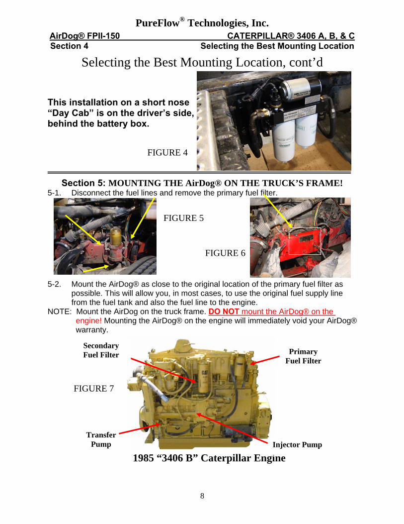
1985 “3406 B” Caterpillar Engine
Secondary Fuel Filter Primary
Fuel Filter
Transfer Pump Injector Pump
PureFlow® Technologies, Inc. AirDog® FPII-150 CATERPILLAR® 3406 A, B, & C Section 4 Selecting the Best Mounting Location
Selecting the Best Mounting Location, cont’d This installation on a short nose “Day Cab” is on the driver’s side, behind the battery box. FIGURE 4
Section 5: MOUNTING THE AirDog® ON THE TRUCK’S FRAME! 5-1. Disconnect the fuel lines and remove the primary fuel filter. FIGURE 5
FIGURE 6 5-2. Mount the AirDog® as close to the original location of the primary fuel filter as
possible. This will allow you, in most cases, to use the original fuel supply line from the fuel tank and also the fuel line to the engine.
NOTE: Mount the AirDog on the truck frame. DO NOT mount the AirDog® on the engine! Mounting the AirDog® on the engine will immediately void your AirDog® warranty. FIGURE 7

9
PureFlow® Technologies, Inc. AirDog® FPII-150 CATERPILLAR® 3406 A, B, & C Section 5 Mounting the AirDog®
MOUNTING THE AirDog® ON THE TRUCK’S FRAME! 5-3. Loose assemble the mounting brackets and filters to the AirDog®. 5-4. Hold the AirDog®, with the brackets and filters attached, next to the frame at the selected mounting location. Check for clearance. If mounted between the frame and steer tire, turn the steering wheel fully to the left and right to check for tire clearance. FIGURE 8 FIGURE 9 5-5. While holding the AirDog® at the selected mounting location on the frame, mark and center punch each hole location. WARNING! DO NOT DRILL INTO OR DAMAGE ANY WIRING, AIR LINES OR OTHER COMPONENTS LOCATED BEHIND THE FRAME RAIL. 5-6. Drill a 3/8” hole at each of the 4 previously marked locations. FIGURE 10
FIGURE 11 5-7. Loose assemble the mounting brackets to the frame. 5-8. Loose assemble the AirDog® on the brackets. Figure 12

10
PureFlow® Technologies, Inc. AirDog® FPII-150 CATERPILLAR® 3406 A, B, & C Section 5 Mounting the AirDog®
5-9. After mounting the AirDog® on the brackets, snug the fasteners to achieve a good relaxed fit. 5-10. Properly tighten all of the fasteners. NOTE: These steps are necessary to prevent stress cracks from forming in the mounting brackets due to road vibration and bouncing. Figure 13
Section 6 Fuel Lines FUEL LINE OVERVIEW
The AirDog® has been engineered to eliminate fuel related problems. It is important that the fuel lines are assembled and installed properly so as not to cause flow restriction. When possible, use the fuel lines that are on the vehicle. This will reduce your installation costs and make the installation go much more quickly. NOTE: On various class 8 trucks, the manufacturer may use other than traditional steel braid fuel lines. These lines require special fittings. The fittings used with the original primary fuel filter are specific to the fuel lines used on the truck. When possible, mount the AirDog® in the location that will allow the use of the original fuel lines and fittings. Inspect the original fuel lines for size, length, and condition. If the fuel lines are in good condition and the correct size and length to adequately reach the AirDog®, you may want to go ahead and use them. If any of the fuel lines need to be replaced, it is recommended that the fuel lines selected meet or exceed DOT requirements. Fuel Supply Line: The fuel supply lines from the tank to the AirDog® and to the engine should be size 10 or, at the absolute minimum, size 8 (1/2” ID). Air/Vapor Return Line: The AirDog® Air/Vapor return line can be connected to the engine’s return line. A size 6 is adequate for the Air/Vapor return line. Primary Fuel Filters: It is most important that there are no fuel filters between the fuel tank and the AirDog® or between the AirDog® and the engine’s transfer pump to plug and cause restriction. These filters should be removed from the system as part of the AirDog® installation. Secondary Fuel Filters: DO NOT REMOVE SECONDARY FUEL FILTERS. This is the filter between the transfer pump and the engine.

113406B Plunger Type Transfer Pump
PureFlow® Technologies, Inc. AirDog® FPII-150 CATERPILLAR® 3406 A, B, & C Section 6 Fuel Lines
Installing the Fuel Fittings and Pressure Sensor Switch!
IMPORTANT: Use diesel compatible thread sealer when installing NPT fittings. NOTE: Figures 14 & 15 illustrate the installation of straight fittings. However, in some instances 90º fittings may be required to connect the fuel lines to the AirDog®.
Two 90º fittings have been included in the kit for this purpose. 6A-1. Install the straight #10 JIC x ½ NPT fuel fitting in the AirDog® fuel port marked
“ENGINE”. Use a 90º swivel fitting as needed when connecting the fuel line.
Figure 14 Figure 15 6A-2. Install a straight #10 JIC x ½ NPT fuel fitting into the fuel inlet port next to the
regulator. Use a 90º swivel fitting as needed when connecting the fuel line. 6A-3. Install the ¼”NPT x #6 JIC Male return fitting into the Air/Vapor return port
marked “TANK”.
Figure 16
Figure 17
6A-4. Remove the 1/8” NPT plug from the end of the pre-installed 450 fitting in the AirDog® base. Install the pressure sensor switch into the 450 fitting.
Use diesel compatible thread sealer on all NPT threads!
Section 6B: Connecting the AirDog® to the Transfer Pump on the Engine!
6B-1. Connect the fuel line that originally connected the primary fuel filter (See Step 5-
1) to the transfer pump to the AirDog® “out to Engine” port. If the fuel line is not in good enough condition or the proper length to make the connection, replace it with a new fuel line!
Figure 18 Figure 19
12
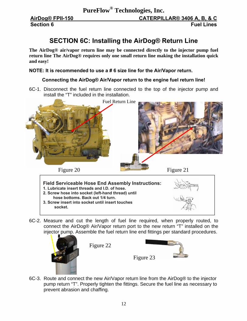
Field Serviceable Hose End Assembly Instructions: 1. Lubricate insert threads and I.D. of hose. 2. Screw hose into socket (left-hand thread) until hose bottoms. Back out 1/4 turn. 3. Screw insert into socket until insert touches socket.
PureFlow® Technologies, Inc. AirDog® FPII-150 CATERPILLAR® 3406 A, B, & C Section 6 Fuel Lines
SECTION 6C: Installing the AirDog® Return Line
The AirDog® air/vapor return line may be connected directly to the injector pump fuel return line The AirDog® requires only one small return line making the installation quick and easy! NOTE: It is recommended to use a # 6 size line for the Air/Vapor return.
Connecting the AirDog® Air/Vapor return to the engine fuel return line!
6C-1. Disconnect the fuel return line connected to the top of the injector pump and install the “T” included in the installation.
Figure 20 Figure 21
6C-2. Measure and cut the length of fuel line required, when properly routed, to connect the AirDog® Air/Vapor return port to the new return “T” installed on the injector pump. Assemble the fuel return line end fittings per standard procedures.
Figure 22 Figure 23 6C-3. Route and connect the new Air/Vapor return line from the AirDog® to the injector
pump return “T”. Properly tighten the fittings. Secure the fuel line as necessary to prevent abrasion and chaffing.
Fuel Return Line

13
1985 3406 B
Secondary Fuel Filter Restrictive
One-way Check Valves
Small, Restrictive Passageway
Hand Primer Pump
PureFlow® Technologies, Inc. AirDog® FPII-150 CATERPILLAR® 3406 A, B, & C Section 6 Fuel Lines
Connecting the AirDog® fuel supply line to the Fuel Tank!
6D-1. Inspect the fuel supply lines that connect the fuel tank(s) to the primary fuel filter for size, length, and condition. If a fuel line has deteriorated or if it is too short to connect to the AirDog®, replace it or make an extension as necessary.
6D-2. If it is necessary to replace the fuel line, measure and cut the length of fuel line
required when properly routed and secured to make the connection from the fuel tank to the AirDog®. Assemble the fuel line per standard procedures.
6D-3. Route the fuel supply line from the fuel tank to the fitting on the AirDog® fuel inlet
port marked “IN”.
Figure 24 Figure 25
6D-4. Connect the fuel supply line from the fuel tank to the fitting. Secure the line to
prevent chaffing and abrasion. SECTION 7: The Caterpillar® Secondary Fuel Filter Modification!
All Caterpillar® diesel engines are equipped with a secondary fuel filter mounted on the engine. The filter head usually has a Hand Primer Pump attached to make priming and starting the engine easier after filter changes.
However, certain passage ways in the filter head and the valves in the hand primer pump are restrictive to fuel flow and negatively affect engine performance.
Figure 26 Figure 27 Figure 28
NOTE: In most cases, the filter head can be drilled out without removing it from the engine!
14
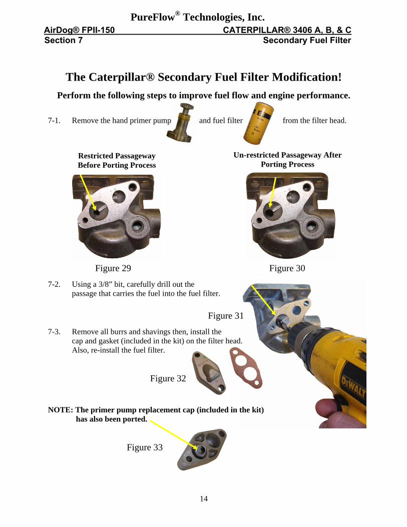
Restricted Passageway Before Porting Process
Un-restricted Passageway After Porting Process
PureFlow® Technologies, Inc. AirDog® FPII-150 CATERPILLAR® 3406 A, B, & C Section 7 Secondary Fuel Filter
The Caterpillar® Secondary Fuel Filter Modification!
Perform the following steps to improve fuel flow and engine performance. 7-1. Remove the hand primer pump and fuel filter from the filter head. Figure 29 Figure 30 7-2. Using a 3/8” bit, carefully drill out the passage that carries the fuel into the fuel filter.
Figure 31 7-3. Remove all burrs and shavings then, install the cap and gasket (included in the kit) on the filter head. Also, re-install the fuel filter.
Figure 32 NOTE: The primer pump replacement cap (included in the kit) has also been ported. Figure 33

15
PureFlow® Technologies, Inc. AirDog® FPII-150 CATERPILLAR® 3406 A, B, & C Section 8 Electrical Harness
ELECTRICAL HARNESS
VERY IMPORTANT: The AirDog® electrical harness requires a MAXIMUM 15 Amp Fuse!
The AirDog® wiring harness has a Microprocessor and two color LED indicator light as standard equipment.
VERY IMPORTANT: The LED Indicator Light will remain green until the first stage of filter plugging. It will then turn RED, indicating the fuel filter needs replacing. Then, if the filter is not timely changed, the light will begin flashing RED.
Additionally, should pressure flow to the engine drop below minimum requirements, the light will immediately begin flashing GREEN. First check the water separator. Then, check the screen in the water separator nipple. Clean or replace as necessary.
The AirDog®, Microprocessor wiring harness. AirDog® Pump Motor Lead Pressure Sensor/Switch Lead Indicator Light & Lead Battery Positive Lead Battery Negative Lead
Relay Lead
Figure 34 Securing the Microprocessor to the Vehicle
8-1. Secure the Microprocessor to the vehicle. This picture shows the Microprocessor mounted next to the steering column.
Figure 35 Figure 36 8-2. Route the pump motor and indicator light sensor lead to the AirDog®. Connect
the 2 pin Deutsch connector on the end of the wiring harness to the pump motor lead.
Figure 37 Figure 38 8-3. Connect the lead with the green seal to the sensor switch.

16
PureFlow® Technologies, Inc. AirDog® FPII-150 CATERPILLAR® 3406 A, B, & C Section 8 Electrical Harness
Routing the Indicator Light and Relay Trigger Lead The Relay Trigger Lead must be connected to a contact point that is electrically “HOT” when the starter key is in the “ON” position. This could be either in the engine compartment or inside the dash such as a spare fuse holder in the fuse panel or on the ignition switch itself. Note: DO NOT connect the relay lead to a point that is “HOT” when the starter key is in the ACCESSORY ON position.
To allow entry for the Indicator Light and Relay Trigger Lead through the firewall:
8-4. Peterbilts and Kenworths have access holes located below the steering column. Remove the plug and route the leads through the hole.
Figure 39 Figure 40 8-5. For other make trucks, drill a 5/8" hole in firewall to allow entry of the Relay Trigger
Lead / Indicator Light harness into the cab. Figure 41 Figure 42 8-6. Route the red, relay trigger wire and indicator light lead through the firewall. Be sure to
seal the opening or install a grommet around the wire loom to prevent water leakage and protect it from chaffing.
Be sure to seal the opening or install a grommet around the wire loom to prevent water
leakage and for protection from chaffing.

17
OR
PureFlow® Technologies, Inc. AirDog® FPII-150 CATERPILLAR® 3406 A, B, & C Section 8 Electrical Harness
Routing the Indicator Light and Relay Trigger Lead, cont’d! 8-7. Connect the Relay Trigger lead to a terminal on the ignition switch that is “HOT” when the ignition switch is in the “ON” or “RUN” position.
Figure 43 Figure 44 8-8. Route the relay trigger lead (Red Wire) to the fuse panel and connect it to a fuse holder that is “HOT” when the key is in the “ON” or “RUN” position.
INSTALLING THE LOW FUEL PRESSURE INDICATOR LIGHT.
Low Fuel Pressure Warning Light Kit! Figure 45 8-9. Select a location on the dash board that is easily visible to the driver. Figure 46 Figure 47 8-10. Remove the dash components as necessary to access the area behind the selected
location.
Ignition Accessory
Battery

18
PureFlow® Technologies, Inc. AirDog® FPII-150 CATERPILLAR® 3406 A, B, & C Section 8 Electrical Harness
INSTALLING THE LOW FUEL PRESSURE INDICATOR LIGHT, CONT’D
8-11. Drill a 9/16” hole at the selected location. Be very careful when drilling. Do not
damage components located behind the dash. Figure 48 Figure 49 8-12. Install the Dash Plate and Indicator Light in the dash. Connect the Indicator Light Lead to the connector on the wiring harness. 8-13. Re-install the removed dash components to their original position.
CONNECTING THE POWER SUPPLY LEADS
The power supply leads can be easily connected to the appropriate contacts on the alternator. However, any high amperage terminal that is always “HOT” is OK for the Positive + (RED) lead. Be sure the NEGATIVE ▬ (BLACK) lead is connected to a reliable Chassis Ground. 8-14. Route the Red & Black power supply leads to the alternator. Connect the Black (-)
ground lead to the alternator Ground connection. Figure 50 Figure 51 8-15. Connect the Red (+) positive lead to the alternator Hot Lead going to the battery.

19
PureFlow® Technologies, Inc. AirDog® FPII-150 CATERPILLAR® 3406 A, B, & C Section 9 Initial Startup
INITIAL START UP PROCEDURE The AirDog® is a self priming system. However, to prevent damage to a dry seal and reduce the life expectancy of the system, pre-fill the water separator/pre-filter with diesel fuel UP TO THE BOTTOM OF THE “NUT PLATE”. 9-1. Pre-fill the water separator/pre-filter with diesel fuel up to the bottom of the nut plate. 9-2. Turn the starter key to the on/run position. 9-3. The AirDog® should now be running and pumping fuel, bleed the fuel line to the engine by loosening the fuel line connection at the engine fitting. As soon as the line is purged of air, tighten the fuel fitting. NOTE: Put a rag or shop towel around the fitting to prevent fuel splatter or spray. Catch all spilled fuel and dispose of properly. 9-4. Start your engine! RECHECK ALL FUEL FITTINGS FOR LEAKAGE AND PROPERLY TORQUE. BE SURE ALL LINES ARE PROPERLY ROUTED TO PROTECT FROM EXCESSIVE HEAT AND SECURED TO PROTECT FROM CHAFFING AND ABRASION. RECHECK ALL ELECTRICAL LINES, SECURE AS NECESSARY.

20
PureFlow® Technologies, Inc. AirDog® FPII-150 CATERPILLAR® 3406 A, B, & C Section 10 Fuel Filter & Pre-Filter
Servicing the AirDog Fuel Filter and Water Separator/Prefilter The AirDog® Microprocessor monitors the fuel filter and water separator!
FUEL FILTER: Plugging of the fuel filter will cause the AirDog® Indicator Light to go from GREEN to RED. Failure to timely service the fuel filter will cause the light to change from RED to FLASHING RED. Replace the fuel filter as necessary!
It is recommended to replace the fuel filter at 25,000 miles of service OR when the Indicator Light turns RED, which ever comes first!
When replacing the fuel filter, be sure to clean the under side of the AirDog® base. It is not necessary to pre-fill the fuel filter with fuel, the AirDog® will fill the filter and prime the system automatically. Follow the instructions on the filter for proper tightening procedures.
Figure 51
The Water Separator/Pre-filter
WATER SEPARATOR: Should the water separator/pre-filter or the wire screen in the nipple become plugged, preventing sufficient operating pressure flow to the engine, the Indicator Light will immediately change from GREEN to FLASHING GREEN.
Check the water separator/pre-filter for plugging. Clean or Replace as necessary! If the light continues to FLASH GREEN, check the screen in the water separator/pre-filter nipple for debris and plugging. Clean as necessary!
Replace the water separator if it becomes damaged or permanently plugged. Servicing of the water separator simply requires draining at regular intervals. It is suggested to check/drain the water separator weekly or as needed should you experience excessive ‘water in fuel’ conditions. Before re-installing the water separator after cleaning, be sure to clean the under side of the AirDog® base. Follow the instructions printed on the water separator/pre-filter for proper tightening procedures. DO NOT over tighten and damage the water separator with a filter wrench.
Caution: Be careful to prevent any contaminates or debris from entering the water separator when remove it for cleaning! Even though the water separator/pre-filter nipple has a protective wire screen, debris could jam the Gerotor and cause the fuse to blow. This is not a warranty item. Should this happen, it is easily put back into working order. See the instructions on “How to R & R the Gerotor” for proper cleaning procedures.
VERY IMPORTANT: The AirDog® electrical harness requires a MAXIMUM 15Amp Fuse!
Dispose of waste fuel and used filters properly to protect OUR environment!
AirDog® Fuel Filter
Prefilter/Water Separator With Drain Valve
Pre-filter Nipple with Wire Screen
(1 1/8th Inch Hex)

21
PureFlow® Technologies, Inc. AirDog® FPII-150 CATERPILLAR® 3406 A, B, & C Section 11 Gerotor & Pump Assembly
Cleaning Debris from the Gerotor Assembly Step 1 Step 2 Step 3
Remove the four (4) socket Carefully remove the O-rings, Remove and clean the gerotor. head cap crews that secure you will need to re-use them. Be very careful not to damage the gerotor cap. the gerotor. Step 4 Step 5 Step 6 Remove the O-rings and clean Replace the center gear. Align and install the outer the inside of the gerotor pocket. gear and O-rings. Step 7 Step 8 1 4 3 2 Install the gerotor cap. Be very Loose assemble the cap careful not to dislodge or pinch screws. Torque the cap the O-rings. screws in an opposing pattern. NOTE: Should any installation problems arise, for assistance please call toll free 1-877-463 4373 or 1-573-635-0555, Monday – Friday, 8:00 AM –4:30 PM CST.
22
PureFlow® Technologies, Inc. AirDog® FPII-150 CATERPILLAR® 3406 A, B, & C Section 12 Pressure Regulator
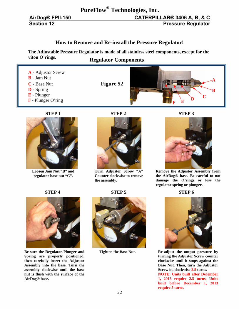
How to Remove and Re-install the Pressure Regulator! The Adjustable Pressure Regulator is made of all stainless steel components, except for the viton O’rings.
A - Adjustor Screw B - Jam Nut C - Base Nut Figure 52 D - Spring E - Plunger F - Plunger O’ring :
A
B C D E
Regulator Components
STEP 1 STEP 2 STEP 3
Loosen Jam Nut “B” and regulator base nut “C”.
Turn Adjustor Screw “A” Counter clockwise to remove the assembly.
Remove the Adjustor Assembly from the AirDog® base. Be careful to not damage the O’rings or lose the regulator spring or plunger.
STEP 4 STEP 5 STEP 6
Be sure the Regulator Plunger and Spring are properly positioned, then carefully insert the Adjustor Assembly into the base. Turn the assembly clockwise until the base nut is flush with the surface of the AirDog® base.
Tighten the Base Nut. Re-adjust the output pressure by turning the Adjustor Screw counter clockwise until it stops against the Base Nut. Then, turn the Adjustor Screw in, clockwise 2.5 turns. NOTE: Units built after December 1, 2013 require 2.5 turns. Units built before December 1, 2013 require 5 turns.
F

23
NOTES

24
Copyright © 2014 Bulletin No. 206-1-0401 CD Patents, LLC Revised January, 2014
All Rights Reserved